MRF Geosystems M1 Radio attachment for handheld sprayers User Manual
MRF Geosystems Corporation Radio attachment for handheld sprayers
UserManual.wiki
>
MRF Geosystems
>
M1 User Manual
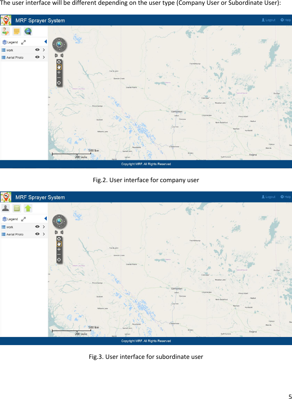
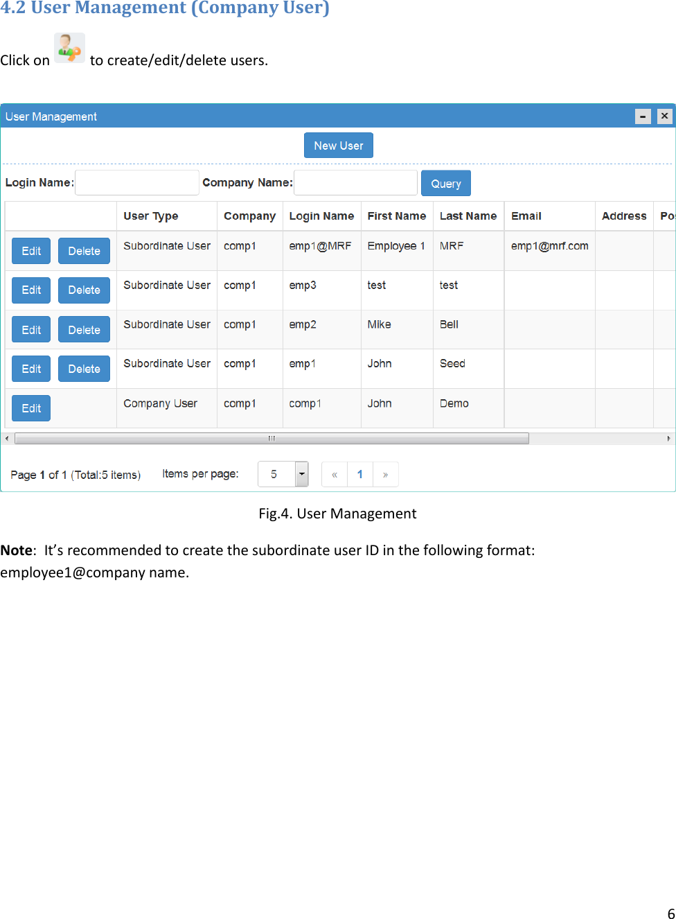
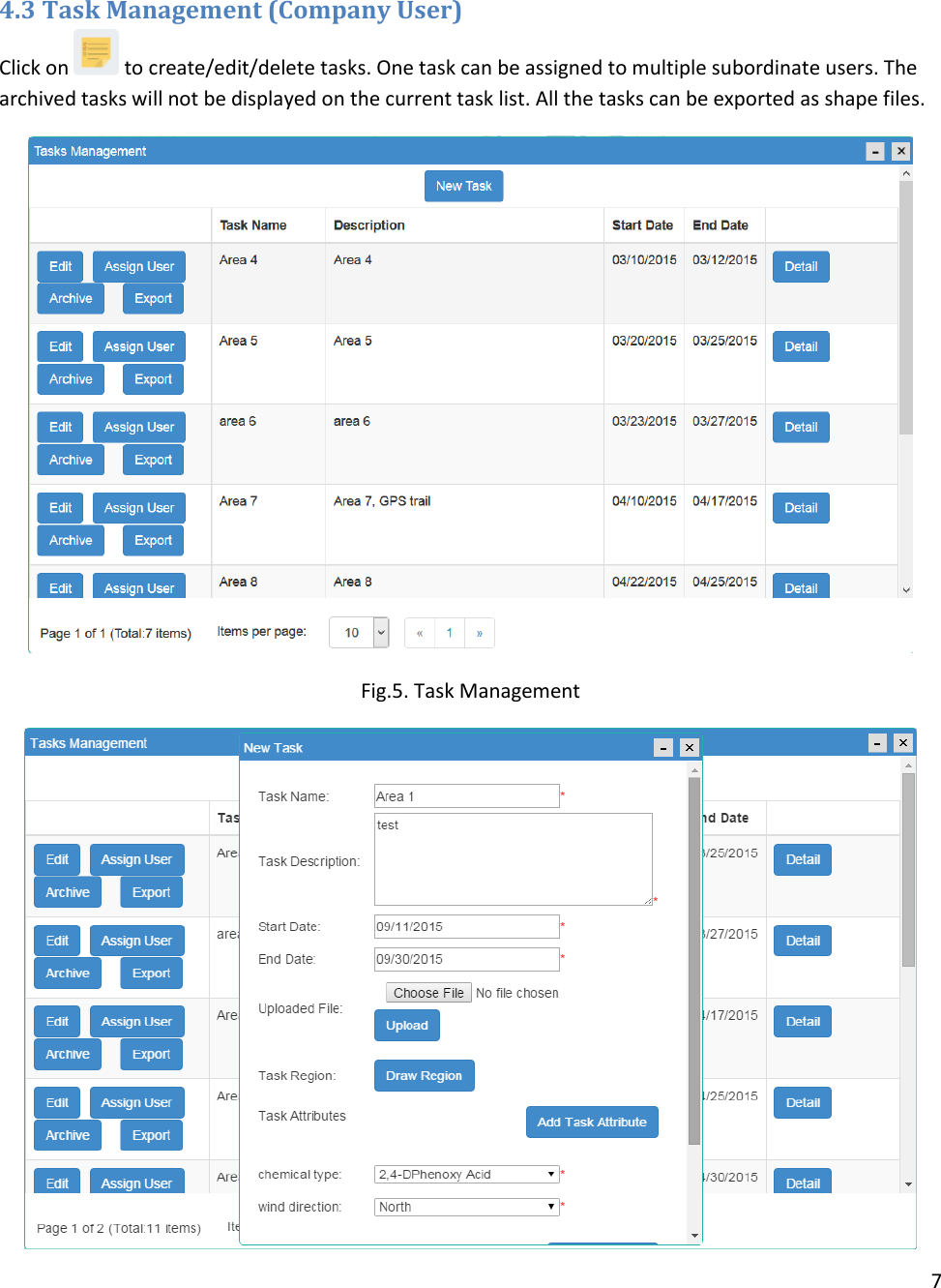
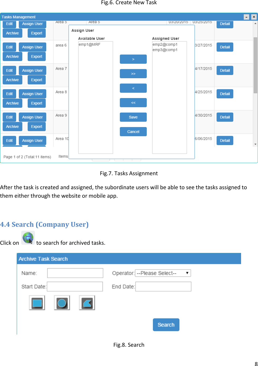
User Manual
Navigation menu
Upload a User Manual
Namespaces
Wiki Guide
HTML
PDF
Info
Views
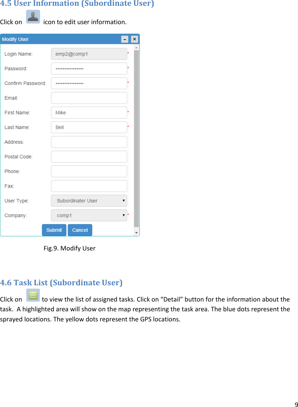
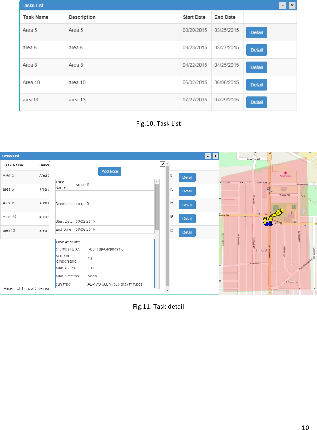
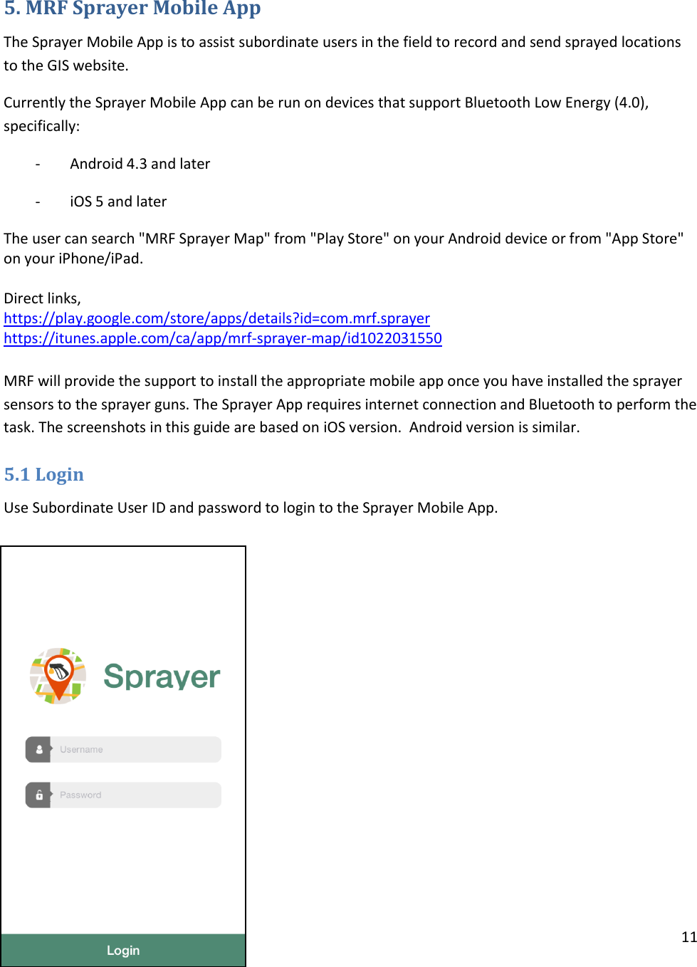
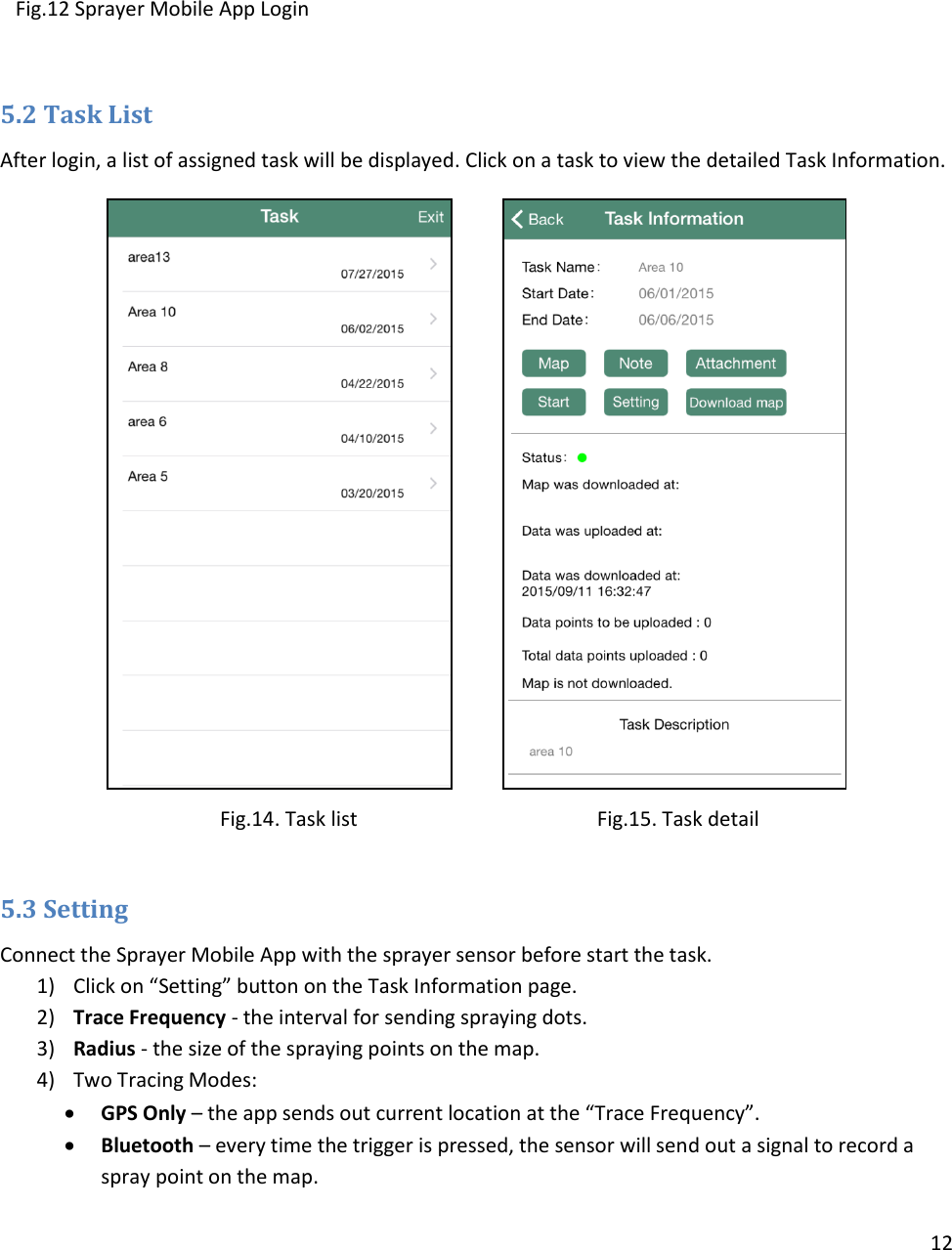
User Manual
Discussion / Help
Navigation