MRF Geosystems M1 Radio attachment for handheld sprayers User Manual
MRF Geosystems Corporation Radio attachment for handheld sprayers
User Manual

1
MRF Grader Blade Up/Down Sensor
User Manual
MRF Geosystems Corporation
Suite 200, 625 – 14th Street NW
Calgary, Alberta, Canada, T2N 2A1
Author
MRF Geosystems Corporation
Last Saved Date
December 15, 2015
Revision
0.1
2
Contents
1. Introduction .............................................................................................................................................. 3
2. Architecture .............................................................................................................................................. 3
3. MRF Bluetooth Sensor .............................................................................................................................. 4
4. MRF HTML5 GIS Website .......................................................................................................................... 4
4.1 User Login ........................................................................................................................................... 4
4.2 User Management (Company User) ................................................................................................... 6
4.3 Task Management (Company User) .................................................................................................... 7
4.4 Search (Company User) ....................................................................................................................... 8
4.5 User Information (Subordinate User) ................................................................................................. 9
4.6 Task List (Subordinate User) ............................................................................................................... 9
5. MRF Sprayer Mobile App ........................................................................................................................ 11
5.1 Login .................................................................................................................................................. 11
5.2 Task List ............................................................................................................................................. 12
5.3 Setting ............................................................................................................................................... 12
5.4 Start ..................................................................................................................................................... 3
5.5 Uploading Notes ................................................................................................................................. 4
Appendix A – MRF Bluetooth Sensor Installation Guide .............................................................................. 5
Tools .......................................................................................................................................................... 5
STEP 1: Verify Sensor ................................................................................................................................ 5
STEP 2: Separate Sprayer .......................................................................................................................... 6
STEP 3: Attach the magnet........................................................................................................................ 6
STEP 4: Modify Sensor (Optional) ............................................................................................................. 6
STEP 5: Attach Sensor Box ........................................................................................................................ 7
STEP 6: Secure Sensor to Sprayer ............................................................................................................. 8
STEP 7: Final Assembly .............................................................................................................................. 9
Appendix B – FCC and Industry Canada Notice .......................................................................................... 12
3
1. Introduction
Spray service companies and municipal field personnel want to identify spray areas for management
records and client reports. MRF Sprayer Solution can get this recording and reports done automatically.
With the help of this sprayer map app, the spray records will be detailed, systematic and professional.
And much more, it’s done automatically, so it will help to reduce the time on preparing the reports and
tracing the record. MRF designed a small Bluetooth sensor attached to the sprayer gun and developed
an app for recording the sprayed area via the smartphone (Patent Pending). The completed tasks can be
viewed online on desktop computers, smartphones and tablets.
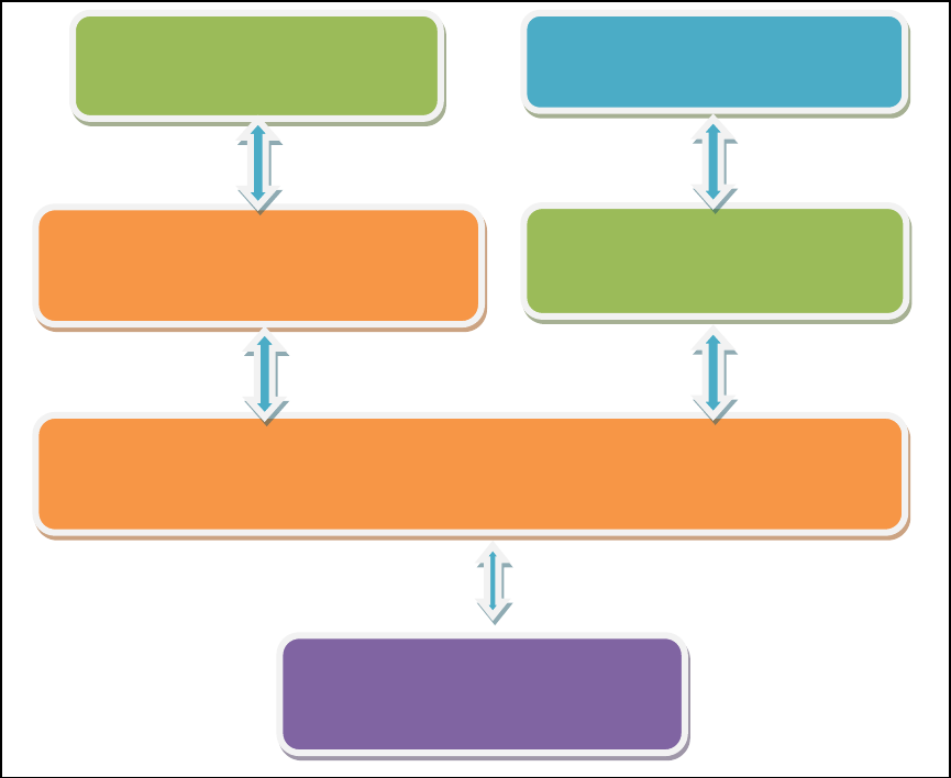
2. Architecture
The following diagram shows the system architecture:
Web Browser
( IE, Chrome, Firefox, Safari)
MRF HTML5 Map Server
(HTML5, JavaScript, CSS, ASP.NET)
Database
( PostgreSQL, PostGIS)
MRF Web Services
(Map Service, User Management, Data Service)
MRF Sprayer Mobile App
(Android, iPhone, iPad)
MRF Bluetooth Sensor
4
3. MRF Bluetooth Sensor
To start, the Bluetooth sensor needs to be attached to a sprayer gun.
Please refer to “Appendix A – MRF Bluetooth Sensor Installation Guide” for sprayer sensor installation
instructions.
4. MRF HTML5 GIS Website
The GIS website provides access for users to view/manage spraying tasks on a map interface. Users can
view areas covered by spraying work in a simple and straightforward way.
After you subscribe to MRF website service, MRF will setup the following user IDs for you:
Company User: eg. MRF
Subordinate User: eg. emp1@MRF
The company user is able to create tasks and assign tasks to employees.
The subordinate (employee) user will see the list of assigned tasks after they login to the website.
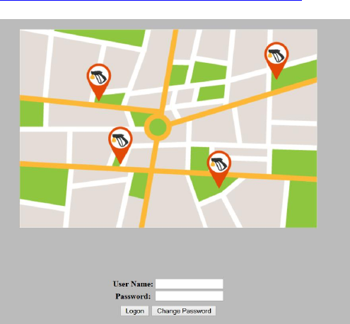
4.1 User Login
Use the credentials provided by MRF to login to the MRF Sprayer GIS website at
http://mrfsprayer.com/SprayerWeb/logon.aspx
Fig.1. User login page
5
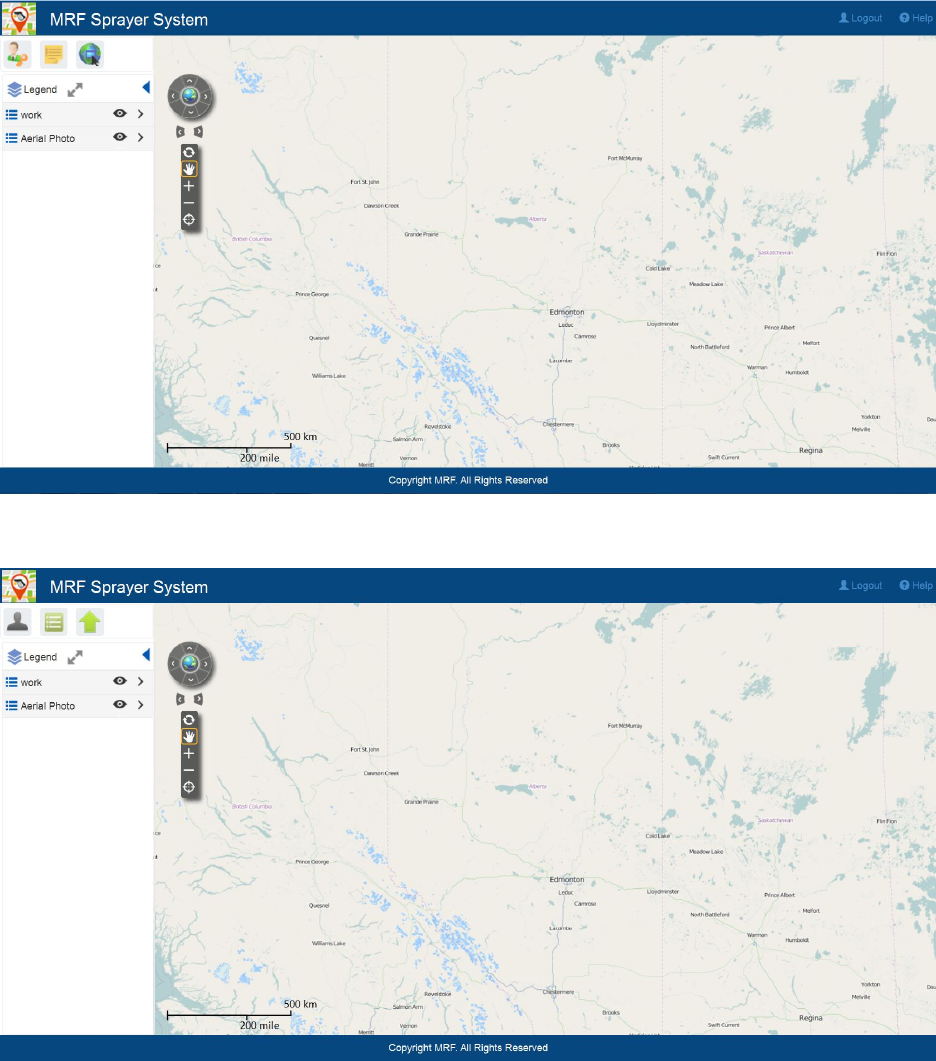
The user interface will be different depending on the user type (Company User or Subordinate User):
Fig.2. User interface for company user
Fig.3. User interface for subordinate user
6
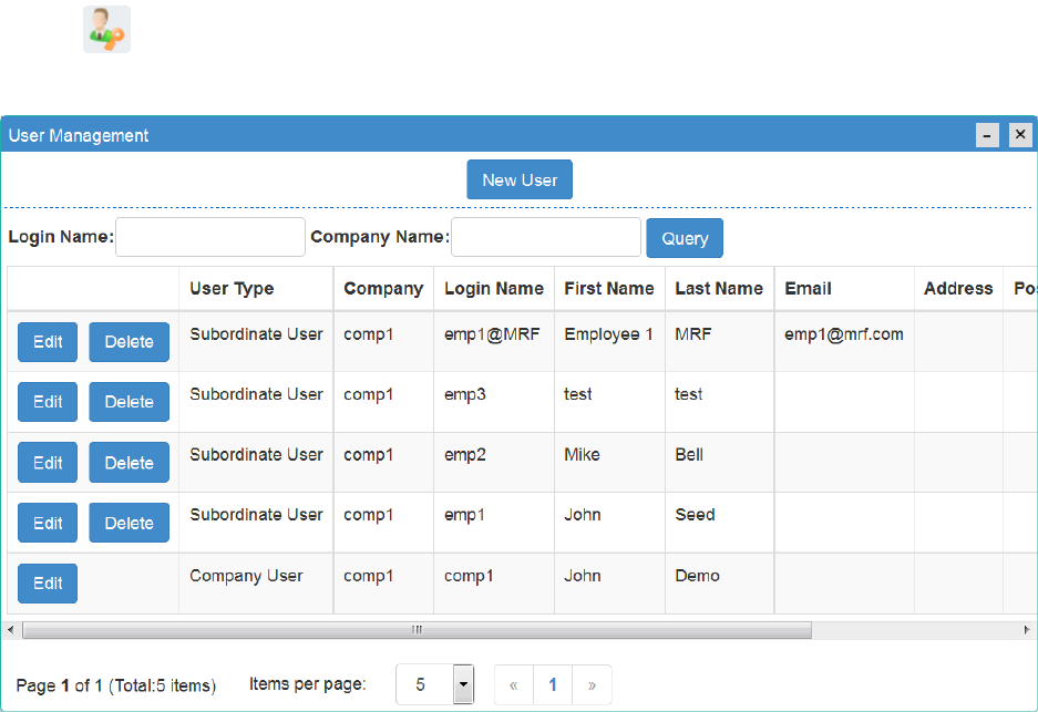
4.2 User Management (Company User)
Click on to create/edit/delete users.
Fig.4. User Management
Note: It’s recommended to create the subordinate user ID in the following format:
employee1@company name.
7
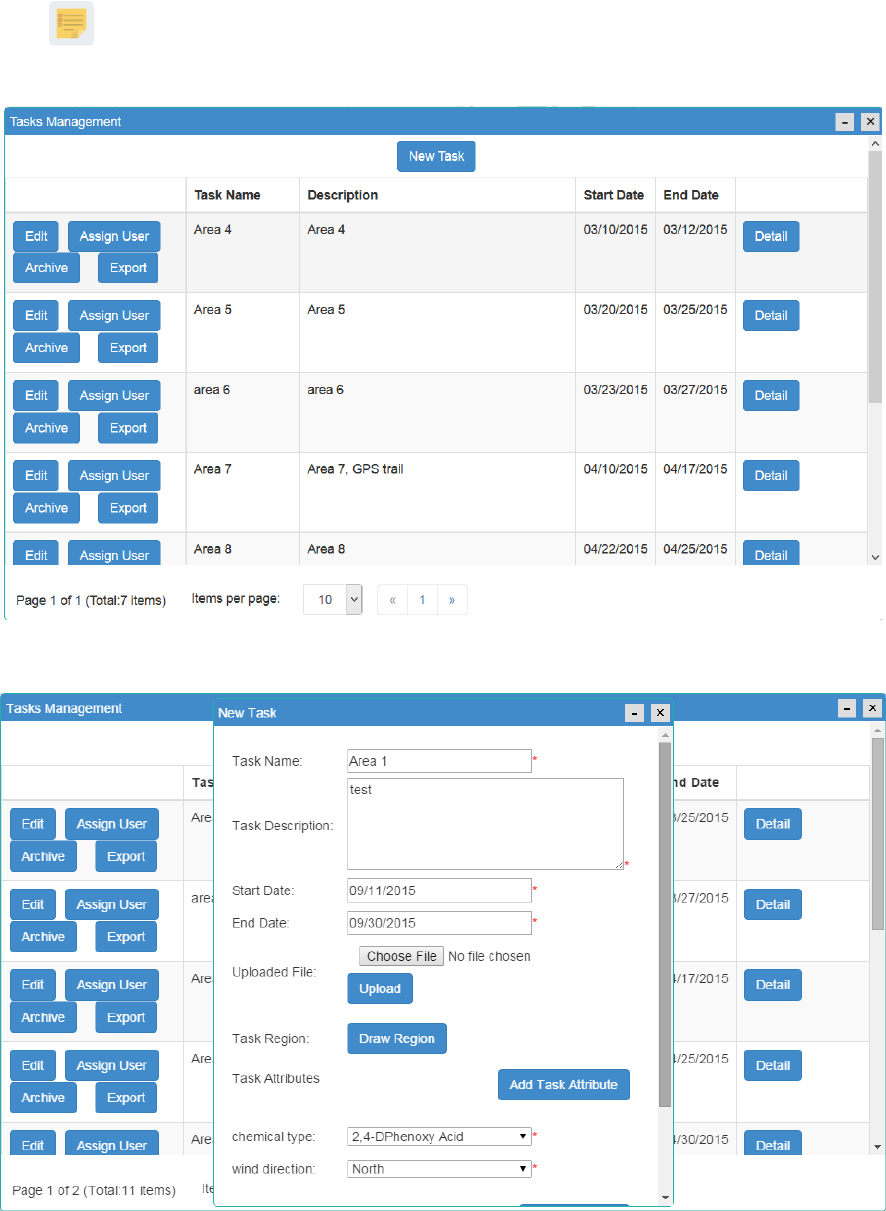
4.3 Task Management (Company User)
Click on to create/edit/delete tasks. One task can be assigned to multiple subordinate users. The
archived tasks will not be displayed on the current task list. All the tasks can be exported as shape files.
Fig.5. Task Management
8
Fig.6. Create New Task
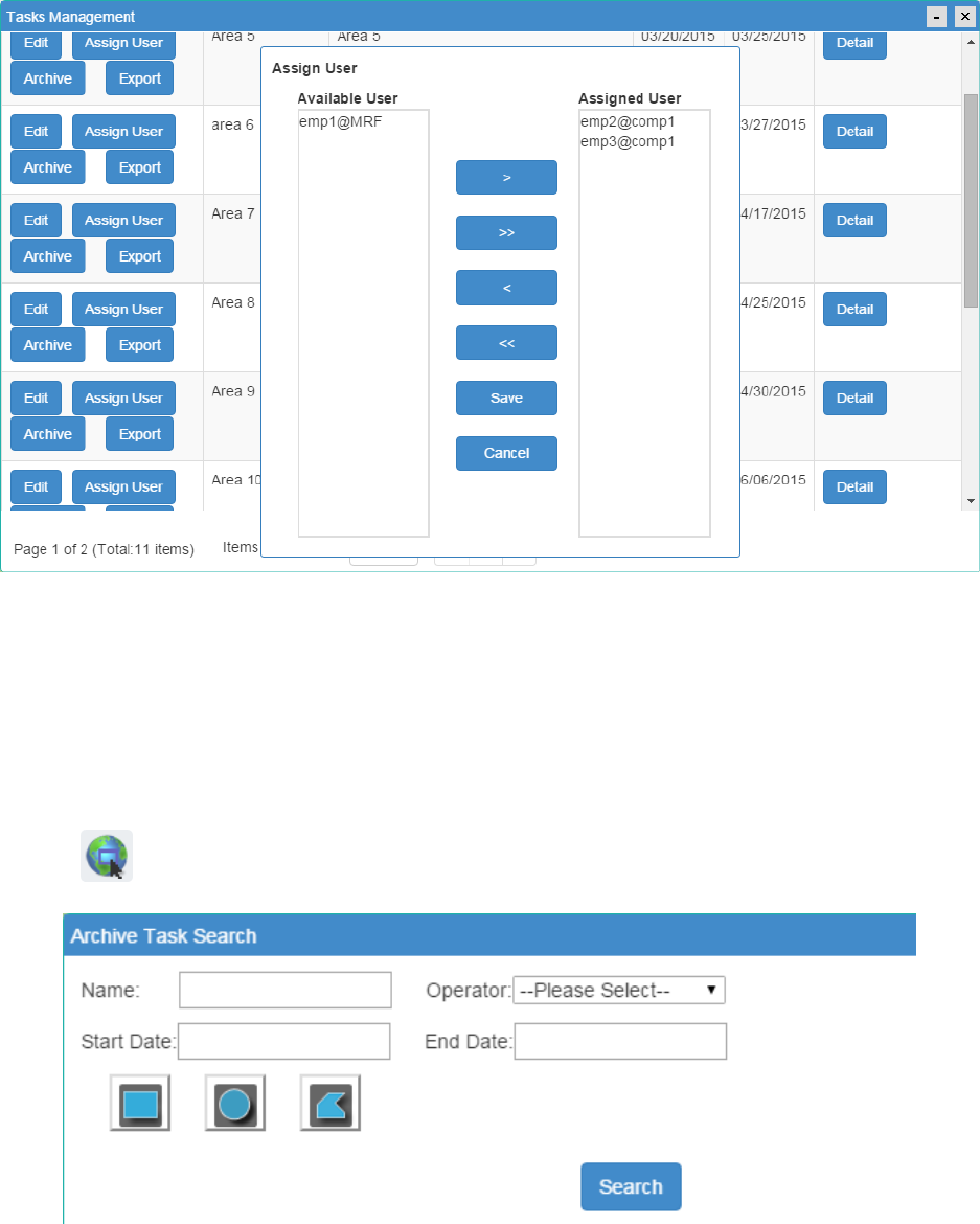
Fig.7. Tasks Assignment
After the task is created and assigned, the subordinate users will be able to see the tasks assigned to
them either through the website or mobile app.
4.4 Search (Company User)
Click on to search for archived tasks.
Fig.8. Search
9
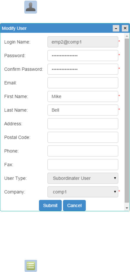
4.5 User Information (Subordinate User)
Click on icon to edit user information.
Fig.9. Modify User
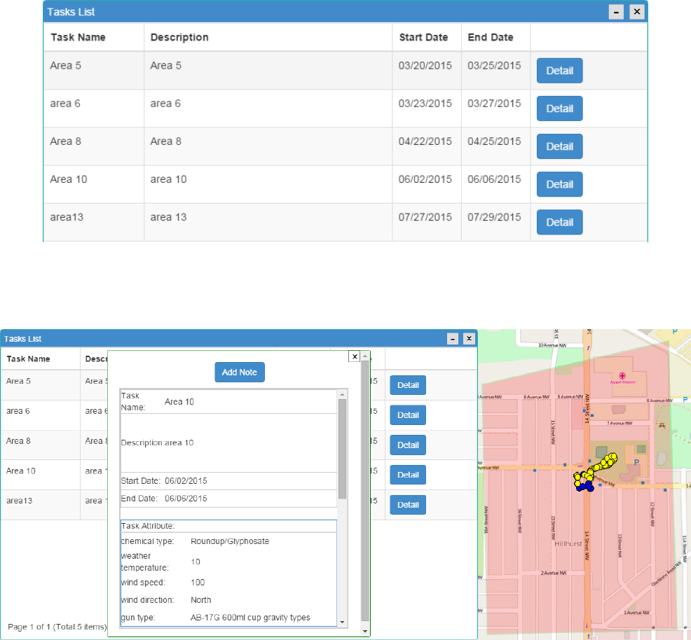
4.6 Task List (Subordinate User)
Click on to view the list of assigned tasks. Click on “Detail” button for the information about the
task. A highlighted area will show on the map representing the task area. The blue dots represent the
sprayed locations. The yellow dots represent the GPS locations.
10
Fig.10. Task List
Fig.11. Task detail
11
5. MRF Sprayer Mobile App
The Sprayer Mobile App is to assist subordinate users in the field to record and send sprayed locations
to the GIS website.
Currently the Sprayer Mobile App can be run on devices that support Bluetooth Low Energy (4.0),
specifically:
- Android 4.3 and later
- iOS 5 and later
The user can search "MRF Sprayer Map" from "Play Store" on your Android device or from "App Store"
on your iPhone/iPad.
Direct links,
https://play.google.com/store/apps/details?id=com.mrf.sprayer
https://itunes.apple.com/ca/app/mrf-sprayer-map/id1022031550
MRF will provide the support to install the appropriate mobile app once you have installed the sprayer
sensors to the sprayer guns. The Sprayer App requires internet connection and Bluetooth to perform the
task. The screenshots in this guide are based on iOS version. Android version is similar.
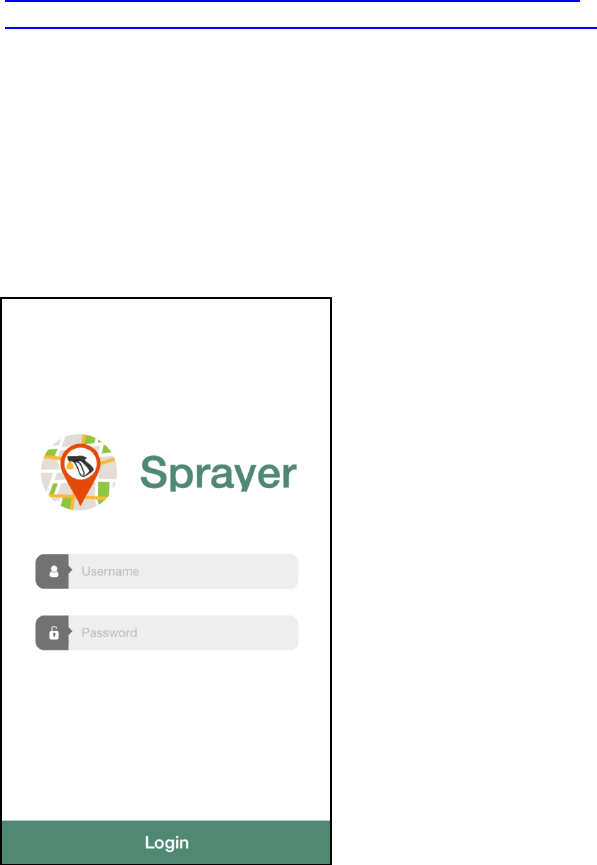
5.1 Login
Use Subordinate User ID and password to login to the Sprayer Mobile App.
12
Fig.12 Sprayer Mobile App Login
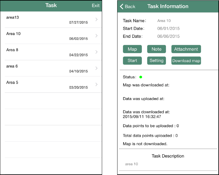
5.2 Task List
After login, a list of assigned task will be displayed. Click on a task to view the detailed Task Information.
Fig.14. Task list Fig.15. Task detail
5.3 Setting
Connect the Sprayer Mobile App with the sprayer sensor before start the task.
1) Click on “Setting” button on the Task Information page.
2) Trace Frequency - the interval for sending spraying dots.
3) Radius - the size of the spraying points on the map.
4) Two Tracing Modes:
GPS Only – the app sends out current location at the “Trace Frequency”.
Bluetooth – every time the trigger is pressed, the sensor will send out a signal to record a
spray point on the map.
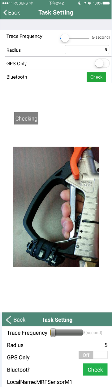
2
Fig.16. Task setting
To set up the Bluetooth, please click on “Check” button. It will start searching for Bluetooth sensors near
you. The status bar should change to . Then press the sprayer trigger in order to synchronize the
Bluetooth between the sprayer and the app (Fig.17).
Fig.17. Pressing Sprayer Trigger
The name of the Bluetooth sensor will appear on the setting page (Fig.18) after connection.
Fig.18. Bluetooth Sensor Name
3
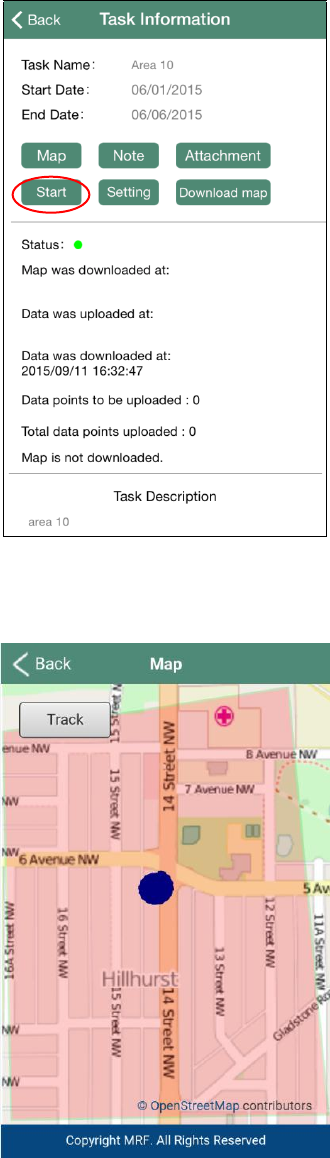
5.4 Start
Click on “Start” button to begin recording spraying positions.
Fig.19 Start
The user can click on “Map” button to view the points locally on the map.
Fig.20. Display Spraying points on a Local Map
4
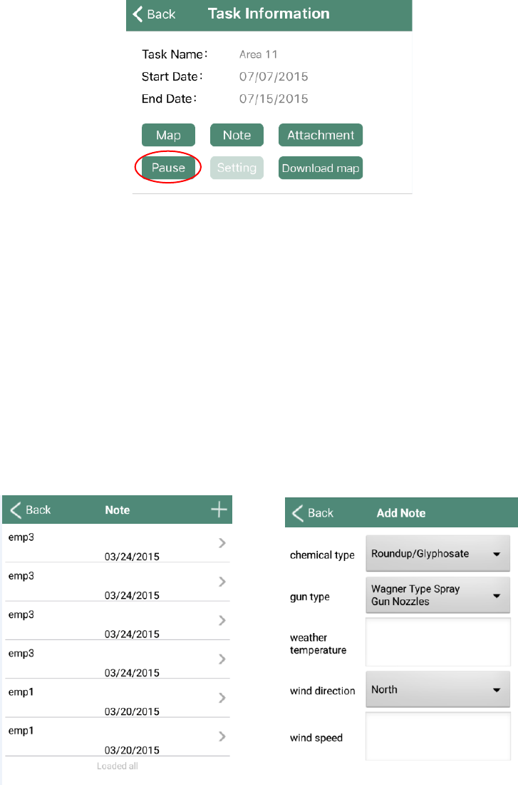
Click “Pause” button to pause the current task.
Fig.21 Stop Sending Spraying Points
The local points will be uploaded to the GIS website later automatically when there is internet
connection.
5.5 Uploading Notes
The user can also view and upload some notes about the spraying task such as chemical type, weather
condition etc.
Click on the “Note” button in the setting page to view a list of notes (Fig.22).
View the note details by clicking on each note from the list.
Create a note by clicking on the “+” sign on the upper right corner.
Fig.22. Note List Fig.23. Create Note
5
Appendix A – MRF Bluetooth Sensor Installation Guide
Tools
Pliers
Philips #1 screwdriver
Drill
1/8” drill bit
Zip ties
Rubber strap
1/8” Pin Punch
Hammer
Metal to Metal Epoxy
Coarse Grit Sand Paper
Neodymium Magnet
MRF Bluetooth Sensor
Tape
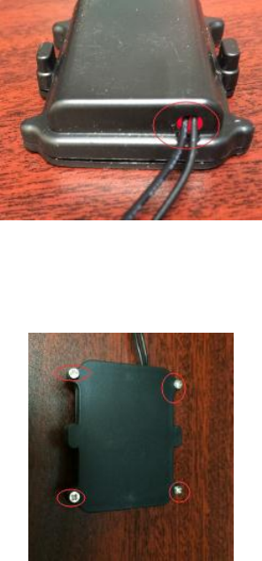
STEP 1: Verify Sensor
Put the sensor box with flat side down on a table. Bring the magnet close to the cylindrical sensor. As the
magnet gets close to the sensor, a faint red light will light up in the sensor box. It will stay lit up for a
second before turning off.
If the light does not light up, try to replace the lithium battery inside the sensor box with a new one.
To replace the lithium battery, use a Philips screwdriver to remove the 4 screws that hold the main
sensor box.
Open the box, replace the lithium battery inside with a new one, then close the box and tighten the
screws. The model of the lithium battery should be CR2032.
6
If the light still does not come on, do not install this sensor. Please contact MRF for support.
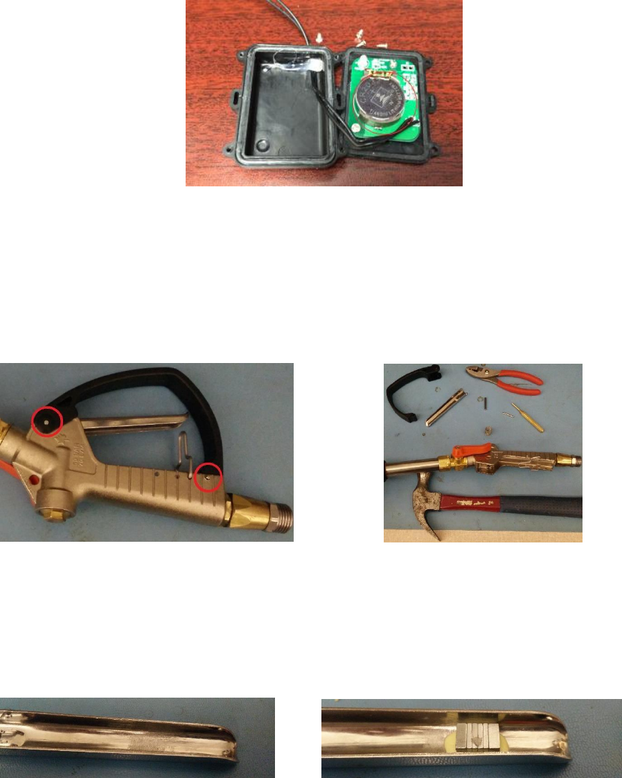
STEP 2: Separate Sprayer
Use a hammer, pin punch, and pliers to remove the two pins holding the finger guard and the lever. Do
not lose any of the parts that come out.
STEP 3: Attach the magnet
Using sandpaper, roughen the inside of the lever about half an inch from the end. This will allow epoxy
to effectively adhere to the lever. Next, put some epoxy on the roughened part, and drop a magnet into
it. Make sure the magnet doesn’t stick out too much. Put the lever to the side and let the epoxy set.
STEP 4: Modify Sensor (Optional)
Use a Philips screwdriver to remove the 4 screws holding the cylindrical sensor.
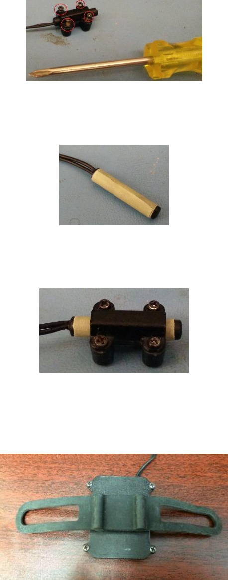
7
Cut a 1” long piece of tape and wrap it around the sensor. The tape should go all the way around the
sensor once, and have a small overlap.
Put the sensor back into its holder and tighten the screws. The cylindrical sensor should no longer slide
in the housing.
STEP 5: Attach Sensor Box
Put the rubber strap on back of the sensor box.
Attach the sensor box to the bottom of the finger-guard with the rubber strap.
8
Secure the sensor box in place with a zip tie. Wrap the sensor wire in the gap between the sensor box
and the finger guard. The sensor should have 2” of wire left coming out of the wrap close to the pin hole.
Use another zip tie to secure the top of the sensor board to the finger guard, locking the wires in
between the two in the process.
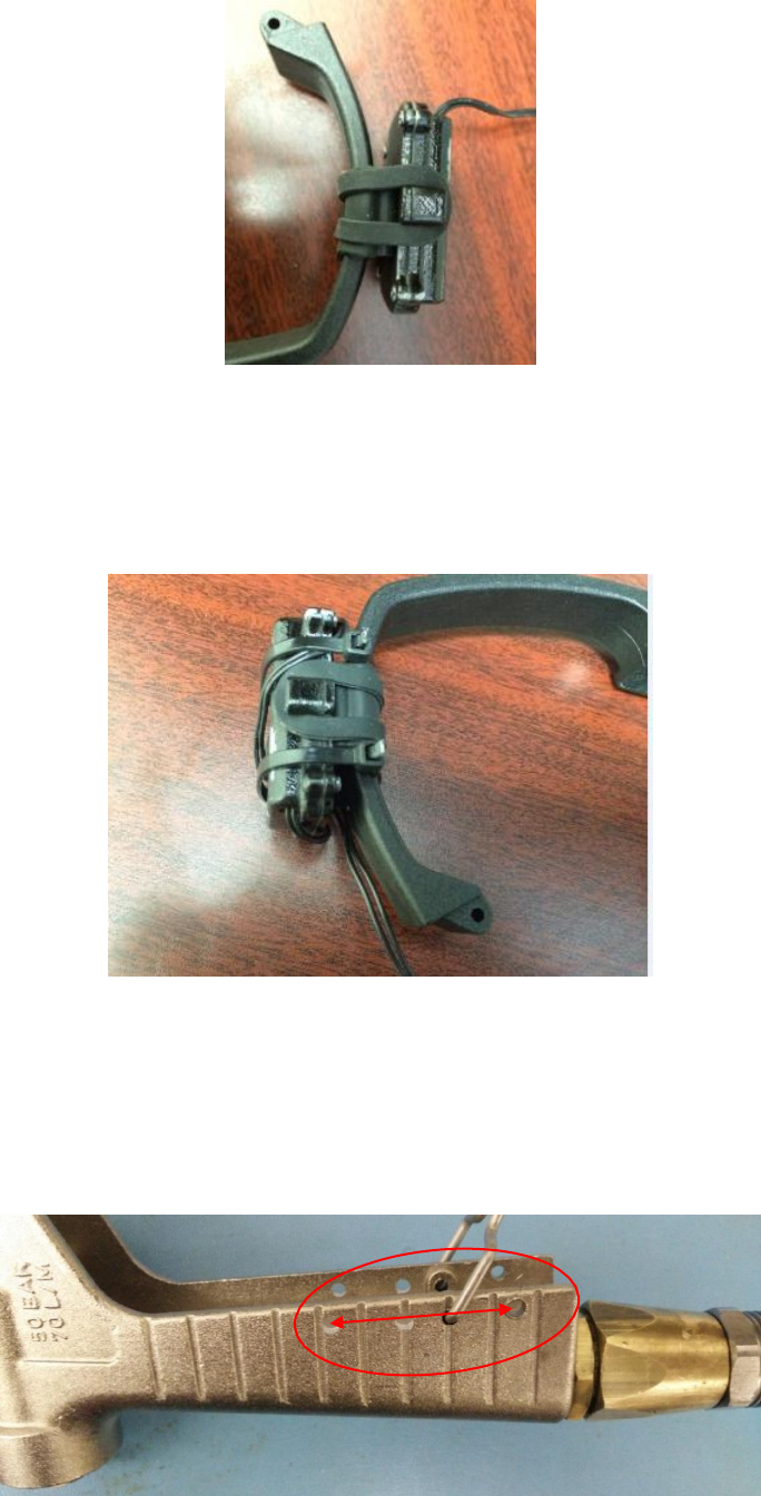
STEP 6: Secure Sensor to Sprayer
Using a 1/8” drill bit, drill a hole about 1 1/4” away from the existing pin hole. The hole should be about
the same distance away from the inside of the handle as the existing pin hole, and the hole should be
through both sides of the handle.
1.2
9
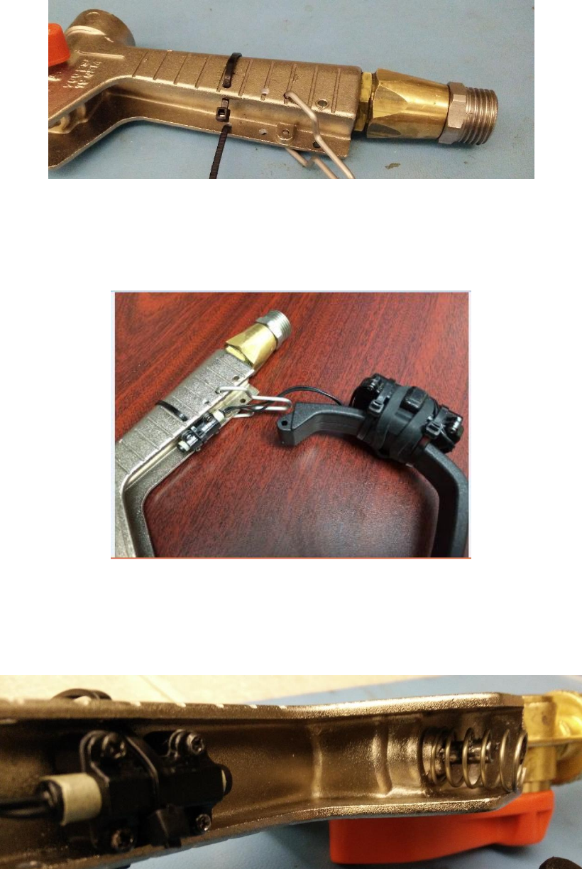
Then feed a zip-tie through both of these holes.
Feed the sensor under the lever lock and put it underneath the zip-tie with the flat part of the sensor
casing against the handle. Tighten the zip-tie and make sure there is no extra slack around the handle, as
it will be uncomfortable to hold.
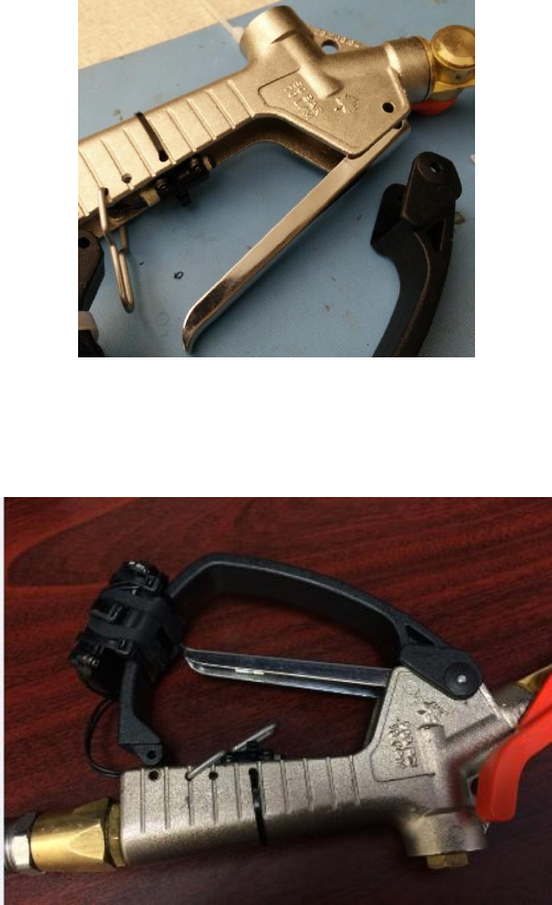
STEP 7: Final Assembly
Put the spring on the engaging pin.
10
Align the holes on the lever with the holes on the handle, compressing the spring slightly.
Align the finger guard holes with the holes on the handle. Make sure the locking lever is not jammed
between the finger guard and the handle when installing the guard.
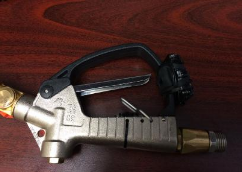
Put the thick pin in first. It should go through the holes closer to the front of the sprayer. The pin should
go through the finger guard, handle, and the lever.
Push the sensor cable to one side of the handle to ensure that it is not getting crushed between the
finger guard and handle. Put the thin pin through the handle and the finger guard.
11
After installation, a faint red light should light up on the sensor box when you pull the trigger.
12
Appendix B – FCC and Industry Canada Notice
FCC Notice to Users
This device complies with part 15 of the FCC Rules. Operation is subject to the following two conditions: (1)
This device may not cause harmful interference, and (2) this device must accept any interference received,
including interference that may cause undesired operation.
Orpyx Medical Technologies Inc. has not approved any changes or modification to this device by the user.
Any changes or modification could void the user's authority to operate the equipment.
Industry Canada Notice to Users
This device complies with Industry Canada's license-exempt RSSs. Operation is subject to the following
two conditions:
(1) This device may not cause interference; and
(2) This device must accept any interference, including interference that may cause undesired operation
of the devices.
Le présent appareil est conforme aux CNR d’Industrie Canada applicables aux appareils radio exempts de
licence.
L’exploitation est autorisée aux deux conditions suivantes:
(1) l’appareil ne doit pas produire de brouillage;
(2) l’utilisateur de l’appareil doit accepter tout brouillage radioélectrique subi, même si le brouillage est
susceptible d’en compromettre le fonctionnement.