MRT LINE-COREM Bluetooth robot User Manual Users manual
MRT INTERNATIONAL LIMITED Bluetooth robot Users manual
MRT >
Users manual


2
content
1. What is LINE-Core M?................................................................................................................................. 3
2. What is LINE-Core M made of ?...............................................................................................................4
LSM-micro, LSC-m, FRAME, BATTERY
3. What is the function of each parts in LSC-m....................................................................................... 5
4. How to charge battery?.............................................................................................................................. 8
5. What should we notice when assemble LINE-Core M.......................................................................9
Notice on assemble and stock .............................................................................................................. 12
6. What should be we confirm before assemble LINE-Core M....................................................................13
7. Part list of LINE-Core M and how to assemble......................................................................................... 14
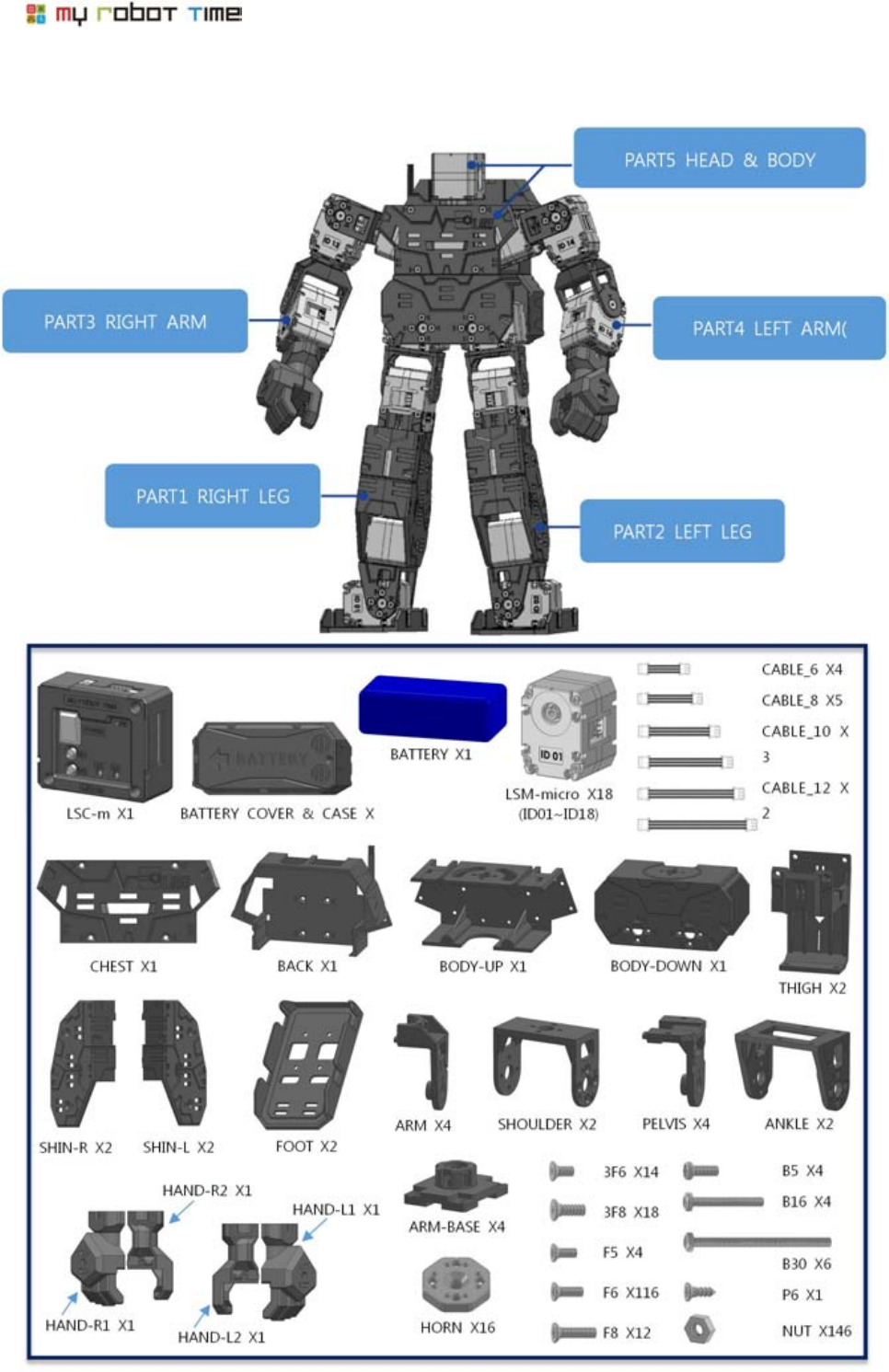
PART1 RIGHT LEG..........................................................................................................................................15
PART2 LEFT LEG.............................................................................................................................................23
PART3 RIGHT ARM........................................................................................................................................31
PART4 LEFT ARM........................................................................................................................................... 35
PART5 HEAD & BODY.................................................................................................................................. 39
8. What is LINE MAKER APP?........................................................................................................................... 53
9.LINE-Core M basic motion introduction and confirmation.......................................................................54
10. How to adjust Zero degree................................................................................................................... 58
10-1. Basic motion adjust.......................................................................................................................... 58
10-2. Slightly change on LSM-micro Zero.............................................................................................62
10-3. Change the center of gravity on assembled LINE-Core M...................................................67
11. How to run LINE Maker APP................................................................................................................. 69
11-1-1. Control Robot............................................................................................................................. 71
11-1-2. Download Process File............................................................................................................. 74
12. How to change LSM-Micro ID...............................................................................................................78
13. How to assemble LINE-Core M kit...................................................................................................... 83
LINE-Core M
3
1. What is LINE-Core M?
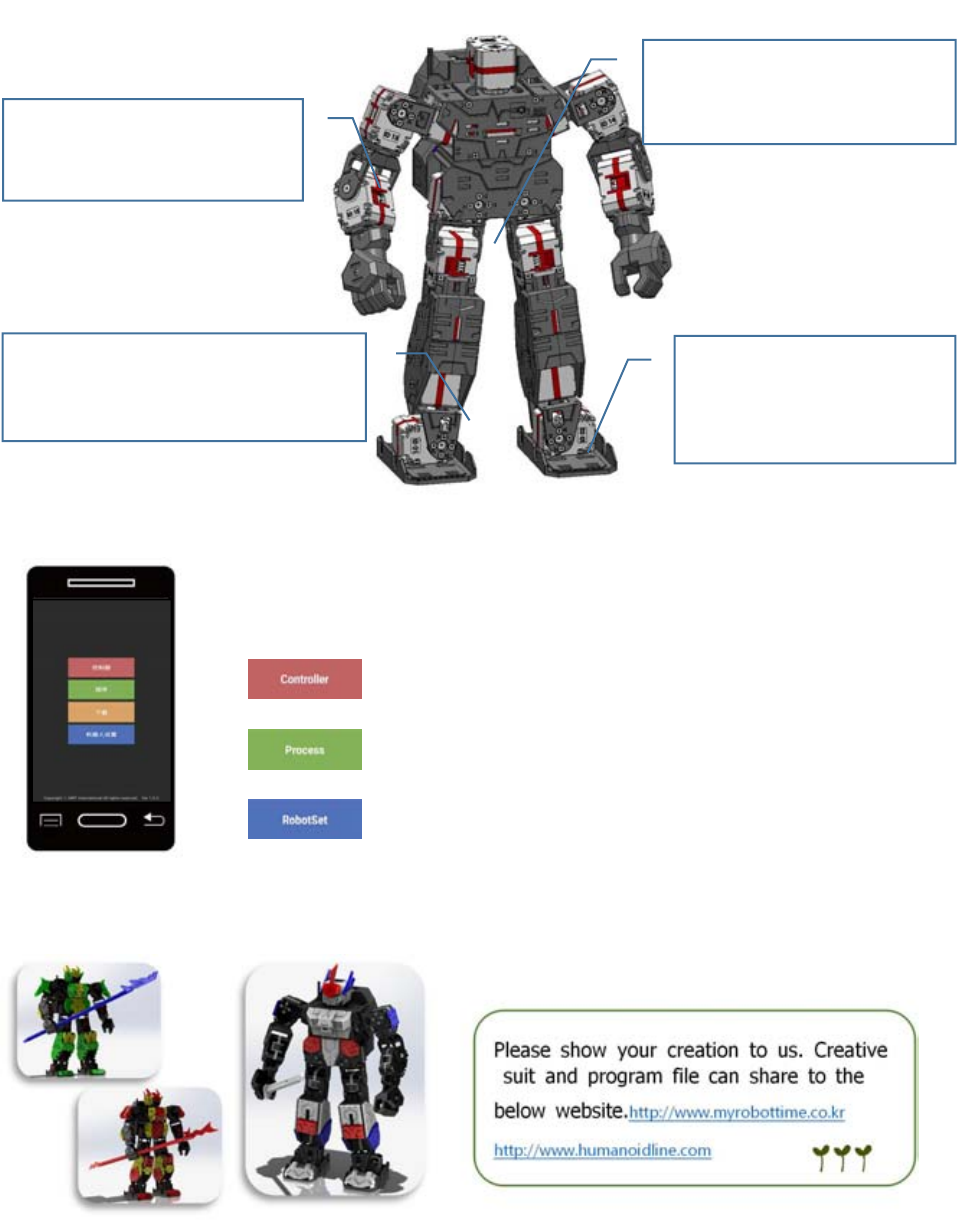
LINE-Core M is the humanoid robot that made of 18 LSM-Micros and have different functions. It
contain Soccer mode, Fighting Mode, Dance Mode, Mission Mode and many other different modes.
This humanoid robot can be used for different robot competitions, develop creative products, robot
education and activities.
▶You can use LINE Maker APP to remote control the robot and can program the motion according to
your requirement
▶Can assemble different roles and suits on robots.
Can rotate around the waist
by using the inside LSM-Micro
Has a prominent assemble
function, very easy to
assemble after use the frame.
Achieve stable walking and
free motion by using 18
different LSM-Micro
Different colors of LED light--Red,
Orange, Yellow, Blue, Purple and s
o on.
LINE-Core M basic motion
User can compile their own program by using LINE-Maker APP.
Can control the robot like the remote controller
Can program robot motion
Can adjust robot zero degree and check robot

4
2. What is LINE-Core M made of
LSC-m
-Use as the special controllor of LINE-Core M and other robot, Like robot
brain
-6 LSM-Micro connect port, can control several LSM-Micro at the same
time.
-Special PC port, can long-range control and download program file
-Can connect smart phone via bluetooth to control robot, program motion
and download program file
-Inside buzzer can indicate the status of robot.
FRAME
-By using the frame which is very good for connection, It is very easy to
assemble several LSM-Micro together
(Please use the provided screws and nuts to assemble)
-Combined with RGB color to show the LED color of LSM-Micro
-Both side have the axis of rotation, drive on both side can be realized
-Can control the location value and rotating force value of LSM-Micro
-Can control the speed of rotate in rotating mode.
-Have connect port on both side, more easy and conveniet to finishing t
he line.
- Torque : 5.3kgf@5V1000mA, stall / - Power : 6.5~9V
LSM-micro
BATTERY
-7.4V Li-Po Battery
-Supply battery cover and battery case
LINE-Core M
5
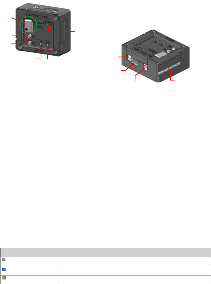
3. The construction and parts function of LSC-m
What is the function of each part in LSC-M
①Power Button
Open/close the robot(when turn down, It is on statues, and turn up, it is off status)
②B1 Button
Supply power for LSC-Micro or run the program or adjust zero for LSM-Micro
③B2 Button
Cut the power of LSC-Micro or stop the current program
④ LED1
Used to check whether supplied power for LSM-Micro or program started or not
LED1 Light
whether supply power to LSM-Micro or not/ Run program or not
Closed
no power supply/no program run
Blue light
power supply/no program run
Green Light
Power supply/Program run
⑦IR Receiver
⑧PC Port
⑨Power connect port
⑩Port for LSM-Micro
(Three each side)
⑥Fireware Button
①Power(on status)
②B1 Button
③B2 Button
④ LED1
⑤ LED2

6
⑤ LED2
Used to check whether LINE-Core m work normally or not and check the balance of battery
⑥Firmware Button
Used to update the LSC-M Firmware
⑦IR Receiver
The place to receiver IR signal
⑧PC port
Used to connect computer and smart phone, for download/run the program or update the
firmware
⑨Power connect port
Can charge though adapter, power bank and so on for LSC-M
⑩Port to connect LSM-Mirco
Work as the port to connect LSM-Micro to LSM-Micro, there is 3 each side(right and left). This six
ports are parallel connection construction, The LSM-Micro can connect to any port in the two
side(except the port for PC)
⑪Other function of LSC-M
-Buzzer inform
LED2
Whether LINE-Core M work or not and the balance of battery
Blue Light
over 60% power remain, LINE-Core M work nornally
Green Light
over 15% Power remain, LINE-Core M work nornally
Yellow Light
around 5% Power remain, Can not do LINE-Core M motion
Red Light
almost 0% Power remain, LSC-Mirco will close
Every 5 second will remind when the light turn yellow, every 2 second will remind when t
he light turn red
LINE-Core M
7
After changed the main setting of LINE-Core M, finished download the program and the balance
of batter not enough, the buzzer will inform this status.
-Bluetooth insert
Used to connect smart phone, Download program and control robot.
-Store and run program file
Can storage and run the program file in LINE-Maker APP
8
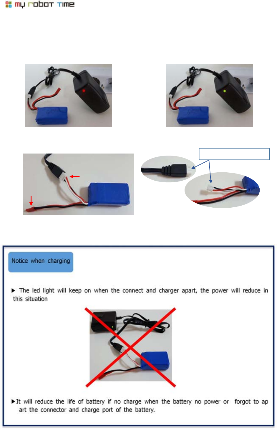
4. How to charge battery
When the motion become slowly or the power become weak, we should charge the battery. It
will be red LED when charging and Green LED when full.
▶The is port for input and output in battery. Please connect the port according to below picture.
▶Time for charging is around 2-2.5 hours, it may difference due to different battery status.
Charge port
Input
Please notice the port.
<charging>
<charging completed>
LINE-Core M
9
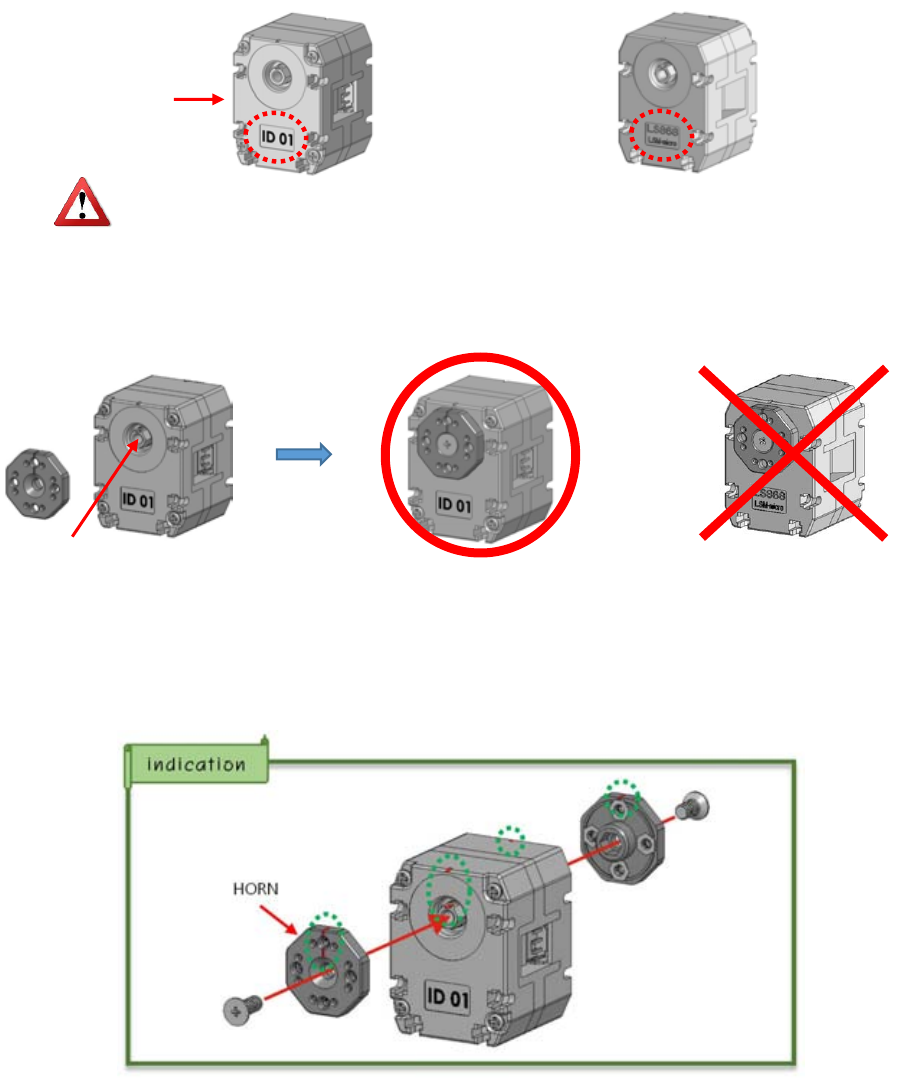
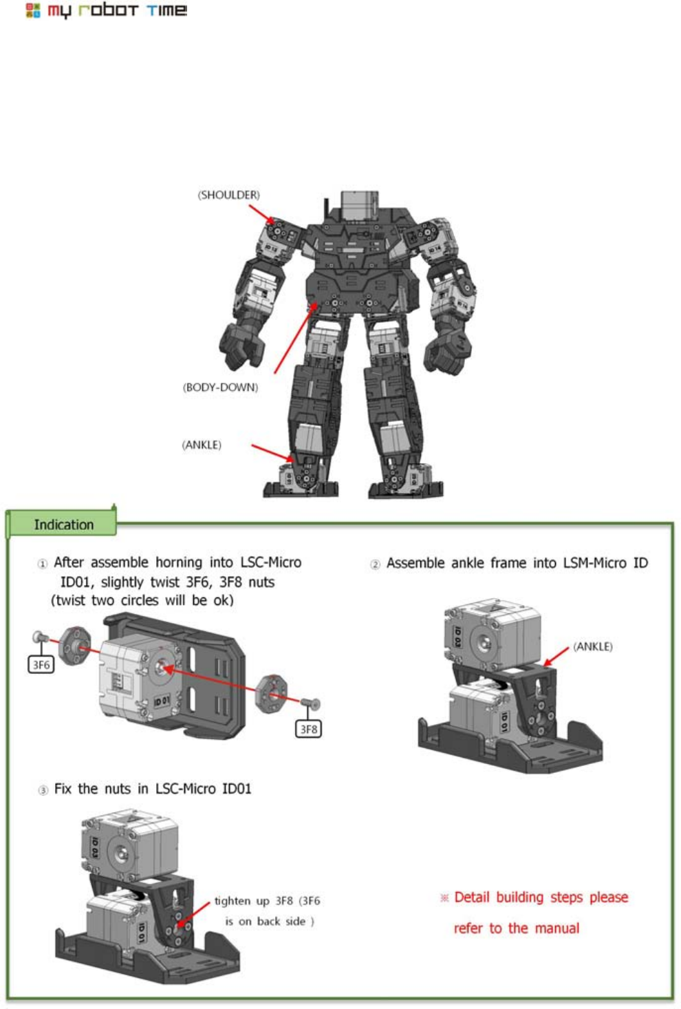
5. Notice when assemble LINE-Core M
LINE-Core M made by 18 LSM-Micros many different strong bindingforce frames and other elect
ronic parts. We need know the following issues before we start to assemble LINE-Core M.
▶The front and back side of LSM is different, the front side marked ID.
▶There is rotation axis in both front and back side. Please use the front side one when only use
one rotation axis.
▶There is a direction marked on LSM-Mirco and Horn. Please confirm the direction location when
assemble the LSM-Micro and horn.
The backside of LSM-Micro will be broken if used alone.
rotating shaft
(Front side: Marked ID)
(Back side)
LSM-micro
please check the manual when assemble LINE-Core, please pay attention to the
ID of LSM-Micro and the direction of each LSM-Micro(Front side and back side)
10
▶Please use No. 3F6 and No.3F8 nuts when making LSM-Micro and horn. Because it maybe
difficult due to the Horn will rotate.
Under this situation, We just put No. 3F6 and 3F8 nuts into LSM-Micro and finish the assmeble of
other parts(such as shoulder,body and ankle) first, then finish the assemble of No.3F6 and 3F8, It
would be easy to assemble if use this method.
LINE-Core M
11
▶There is 6 port in LSM-Micro to control LINE-Core M motion, the wire can connect into any port in
LSC-M, but can not connect to the port which special for computer.
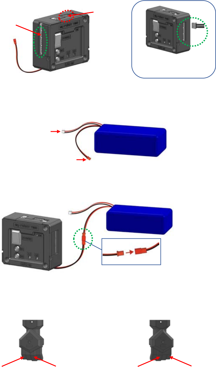
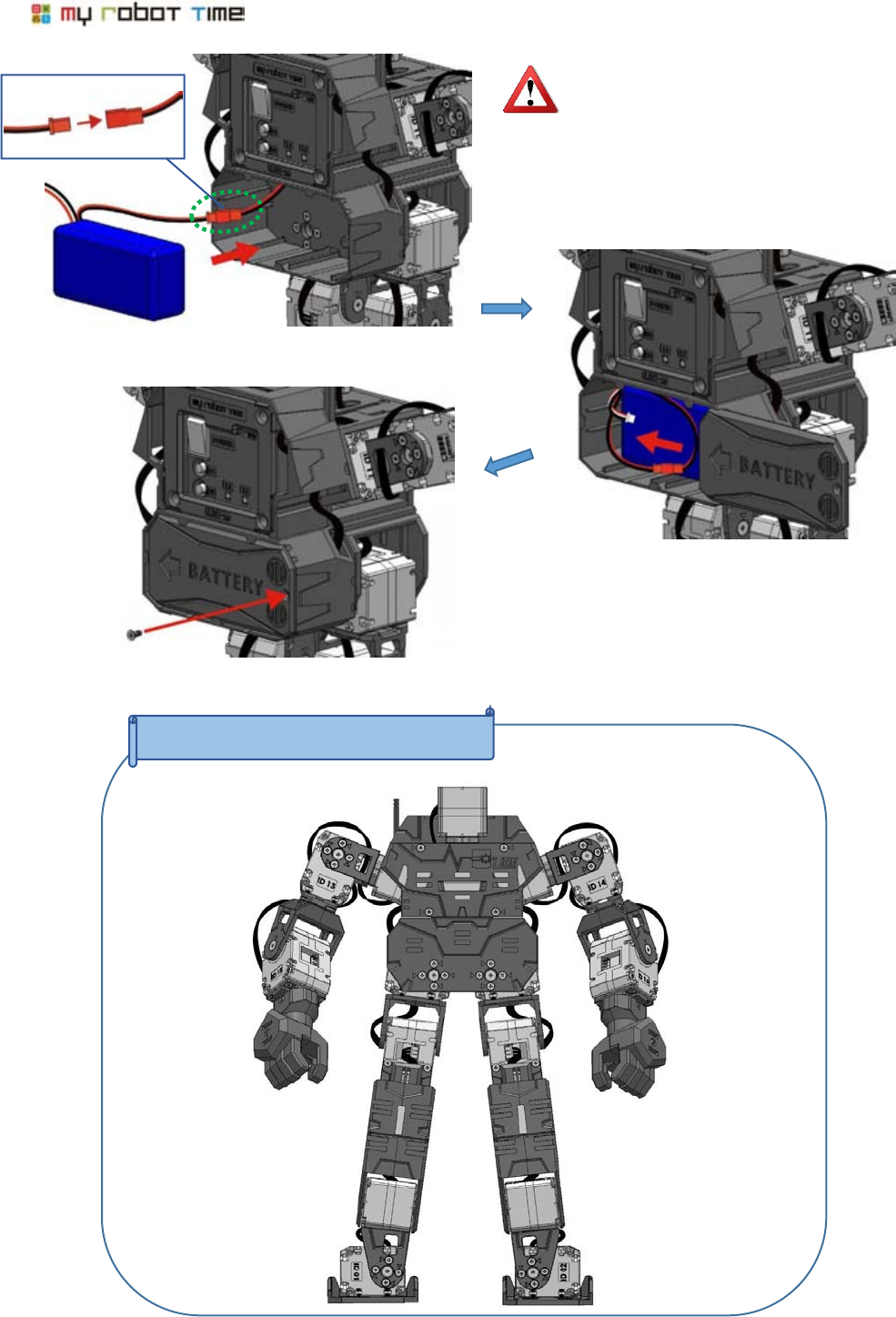
▶There is two wire listed below in battery, please choose the right wire for different purpose.
①Charging wire: used for charging and connect to charger.
②Connect with LSC-M wire together , used when control the robot and output wire color
should be connected with the same color wire in LSC-m.
▶Hand-R1 and HAND-L1 looks like the same, but we can see the differences from the finger and
length.
HAND-R1
HAND-L1
Little finger the shortest
Mid finger the longest.
Mid finger
Little Finger
Red
Black
Red
Black
①for charging
②for output
Special for PC.
LSC-m have port for connect
in both right and left side.
LSM-Micro have three port
each side.
LSC-m
Please notice the connect
direction when connect
LSM-Micro wire.

12
Notice for assembly and Stock
▶Please use official parts and tools when assembling the robot, please do not use the chang
ed wire, motor, knife and other dangerous tools.
▶Please do not over forced when assembling the robot.
▶Please make sure the robot stay in flat ground when programming or motion to avoid drop
from high place.
▶If the robot can not work normally, please notice the building steps, the balance of battery
and the wire connection of the motors.
▶Please turn off the robot if there is anything wrong with the robot joint.
▶Please note that do not let the fingers to touch the robot joints.
▶Please do not lose the parts and robot, do not use wet hand to touch the robot.
▶Please do not place the robot under the environment where too hot or too wet.
▶Please keep your face far away from the robot.
▶Please note that there is many small parts in the robot kit, Please take care of your kid
and avoid choking.
▶Robot should make by the user and Please be careful when assembling the robot, user should be
responsible for the wrong handle and uncorrected assembly.
LINE-Core M
13
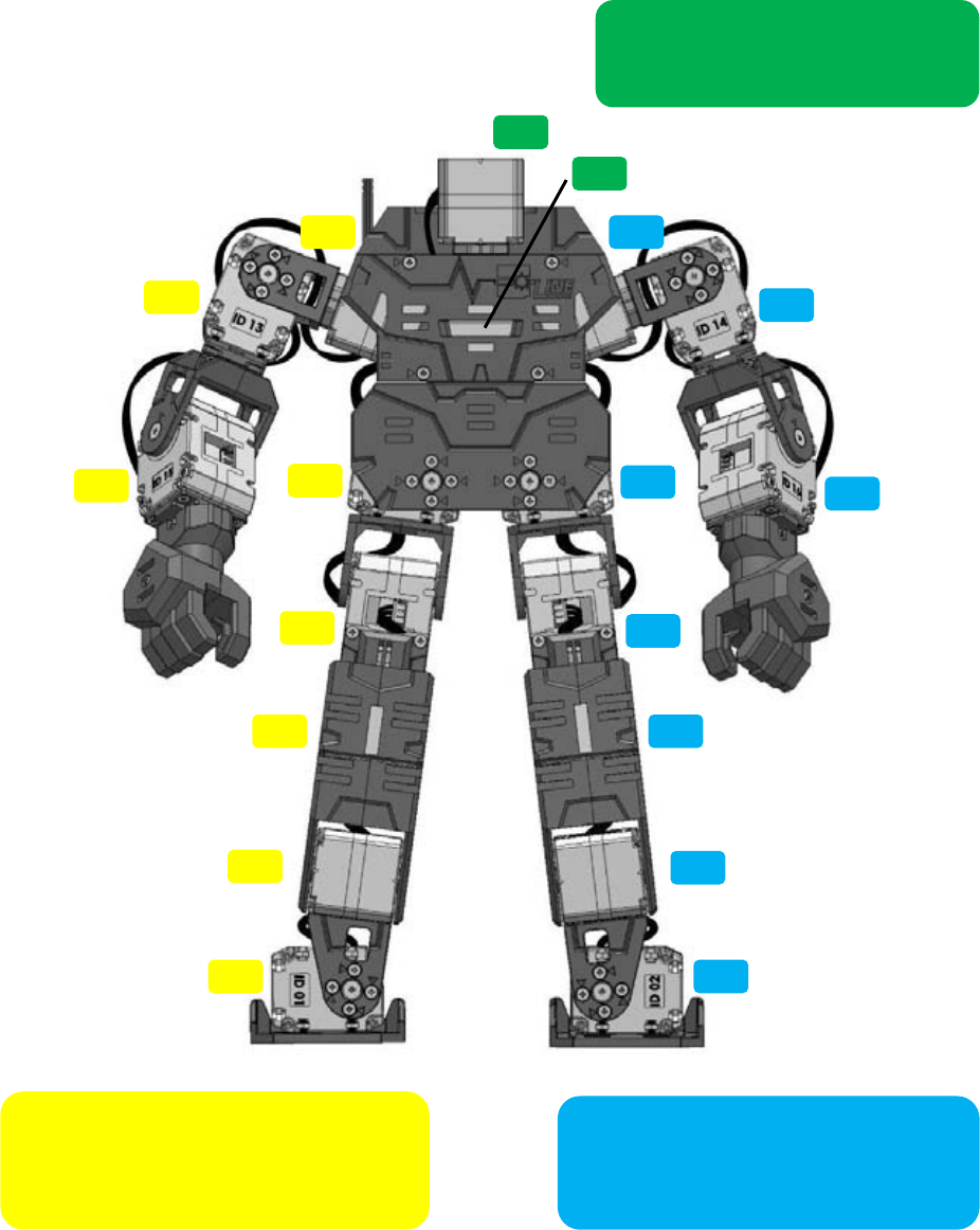
6. What should we confirm before to make LINE-Core M?
Left leg and arm should be assembled
in front side or outward side(the side
where should ID), please refer to the
manual.
ID18
ID17
ID11
ID13
ID15
ID09
ID10
ID12
ID16
ID07
ID05
ID03
ID01
ID08
ID06
ID04
ID14
ID02
Right leg and arm should be assembled
in front side or outward side(the side
where should ID), please refer to the
manual.
LSM-micro ID17,ID 18 front side
(the side where showed ID)
downward assembly.
14
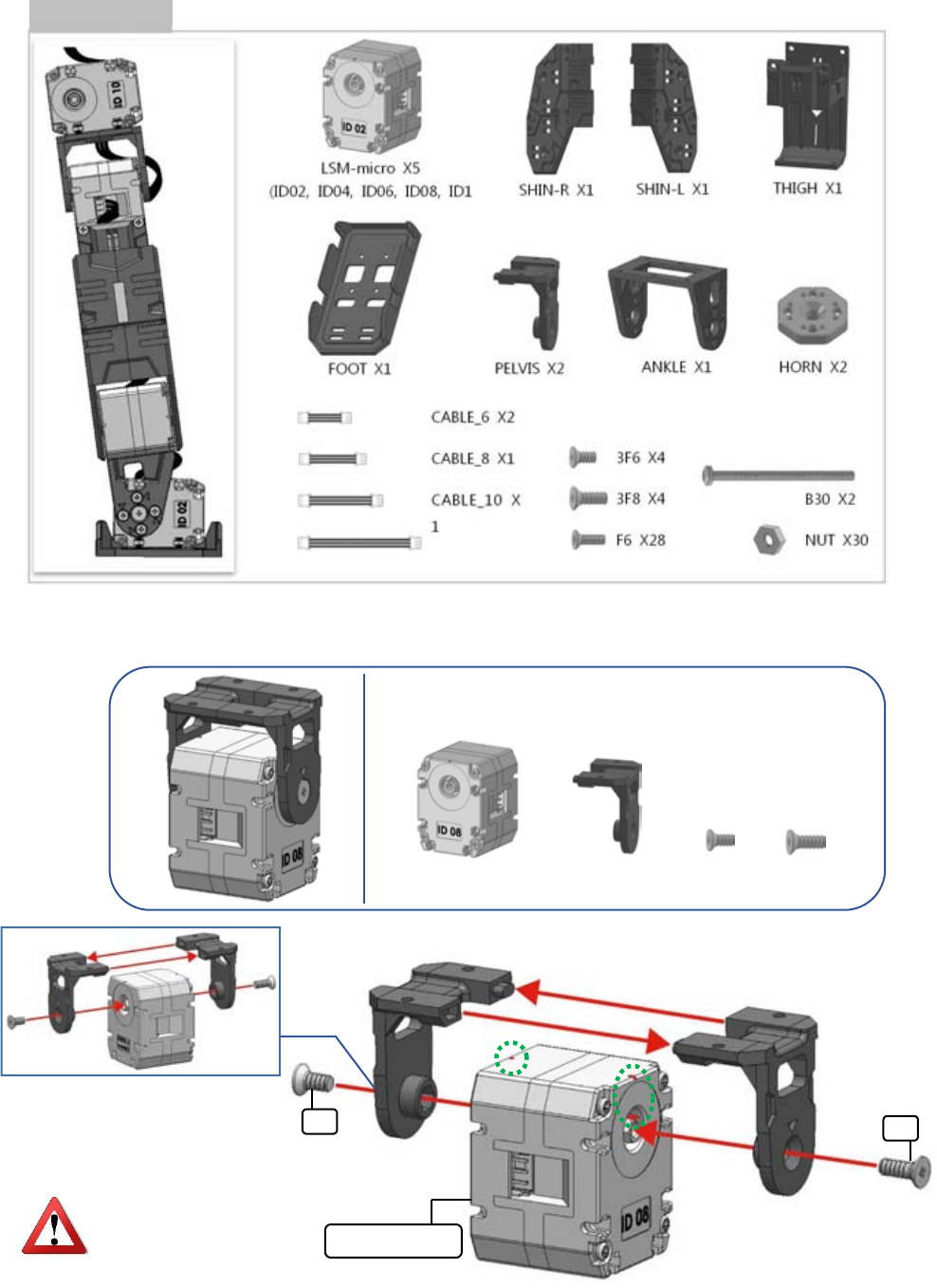
7. The part list of LINE- Core M and how to assemble it.
LINE-Core M
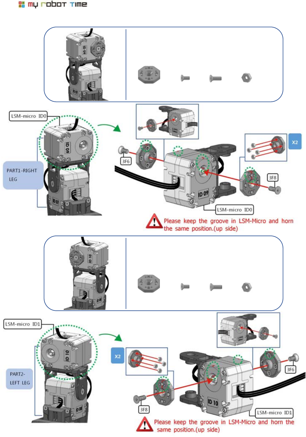
15
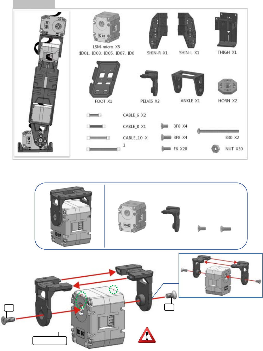
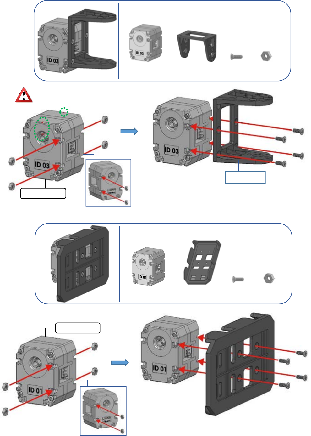
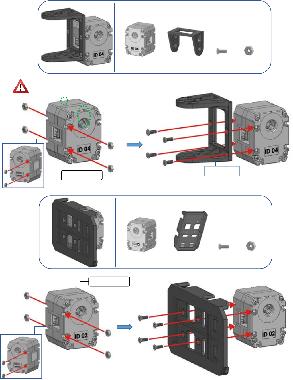
PART1 RIGHT LEG
PART1-1
3F6
3F8
LSM-micro ID0
Please notice the groove in LSM-Micro
(up side)
3F6 X1
LSM-micro(ID07) X
3F8 X1
PELVIS X2
16
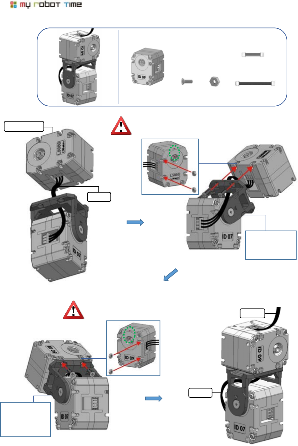
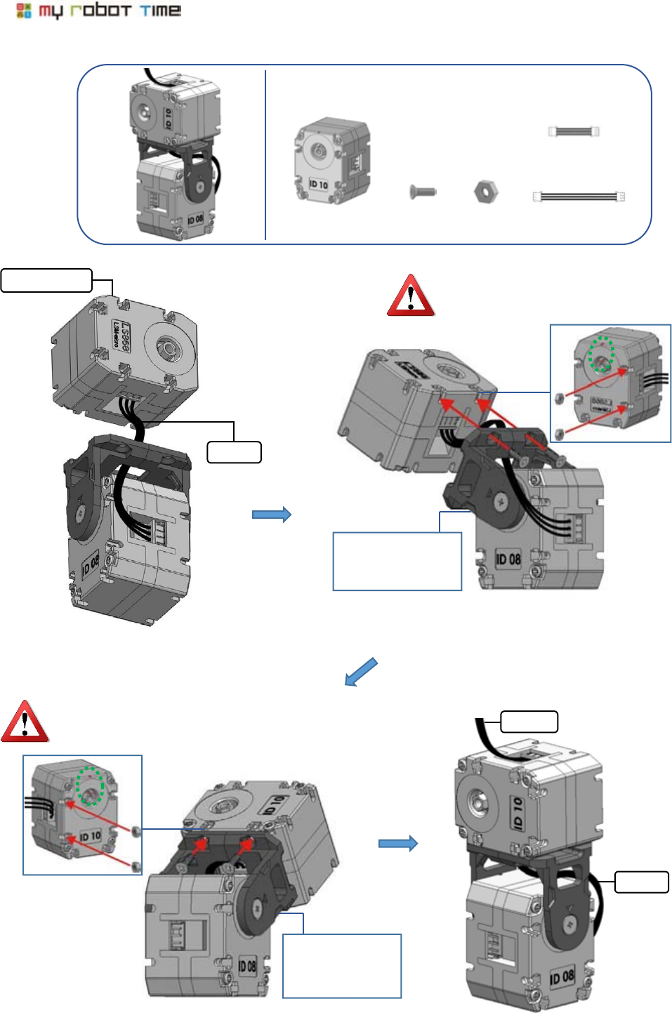
PART1-2
Please notice the groove in LSM-Micro (up side)
Please turn the
pelvis backward
90 degree
LSM-micro ID0
CABLE_8
Please notice the groove in LSM-Micro (up side)
Please turn the
pelvis backward
90 degree
CABLE_16
CABLE_8
F6 X4
CABLE_8 X1
NUT X4
LSM-micro(ID09) X
CABLE_16 X
LINE-Core M
17
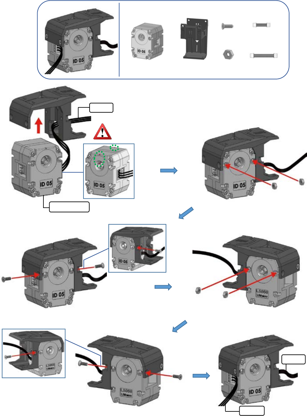
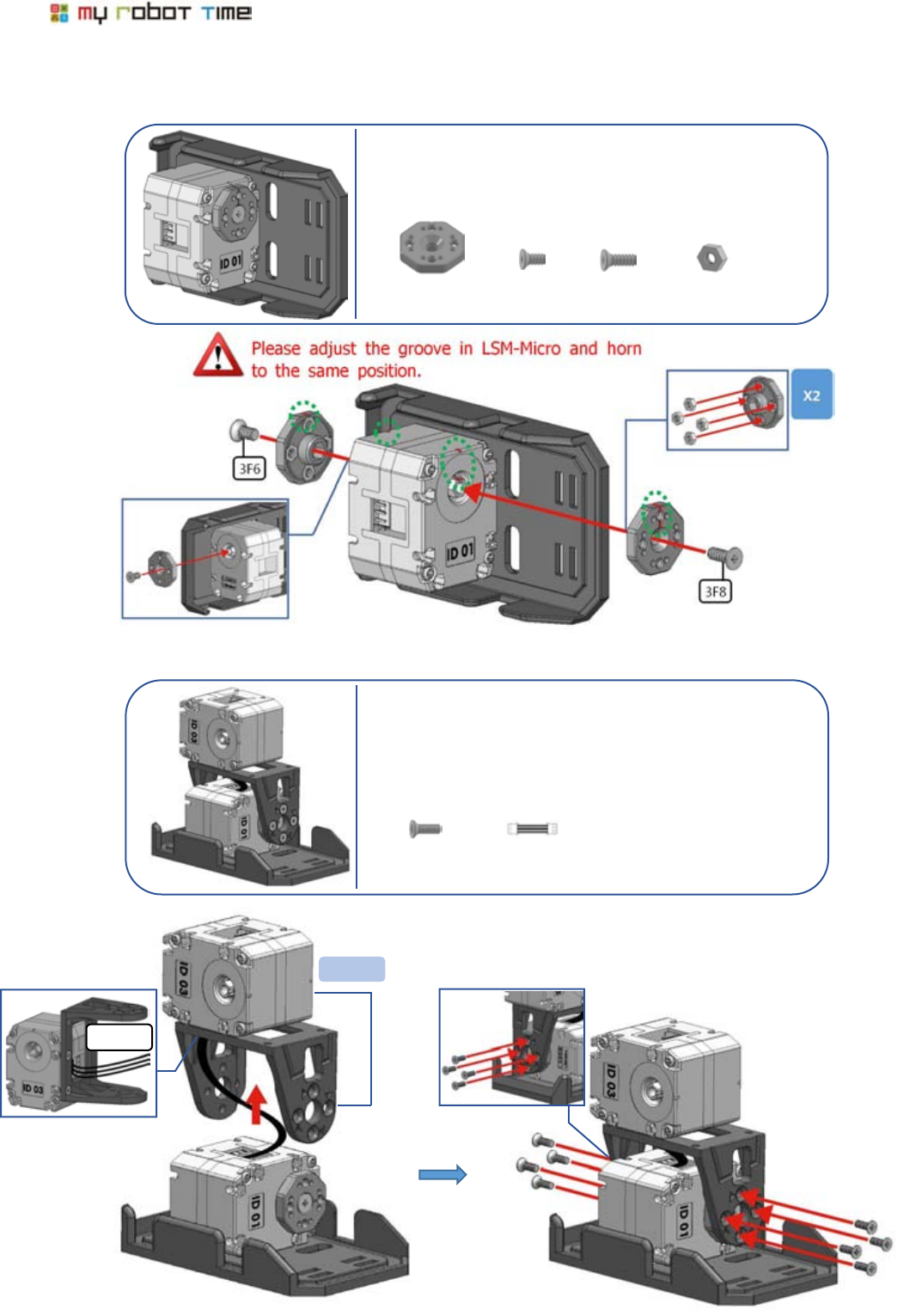
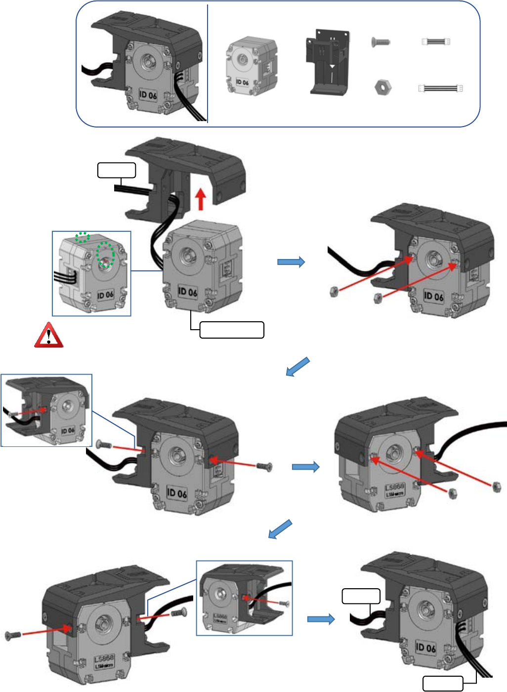
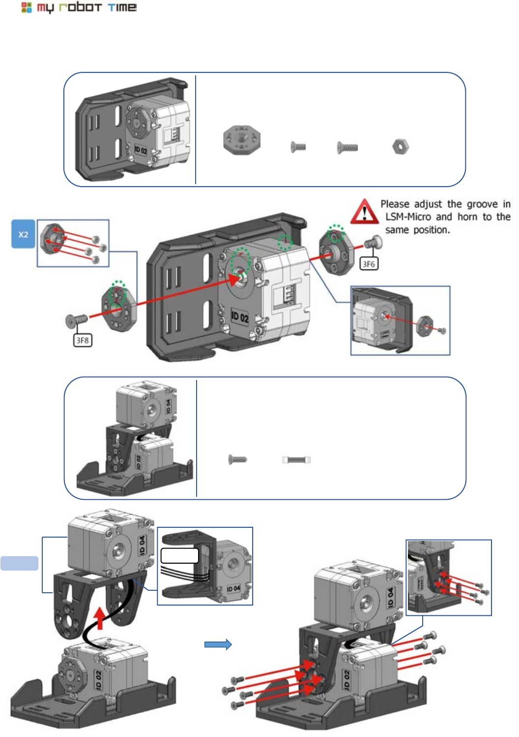
PART1-3
Please notice the groove in
LSM-Micro (up side)
LSM-micro ID0
CABLE_6
CABLE_10
①
②
CABLE_6
LSM-micro(ID05) X1
NUT X4
CABLE_6 X1
CABLE_10 X
F6 X4
THIGH X1
18
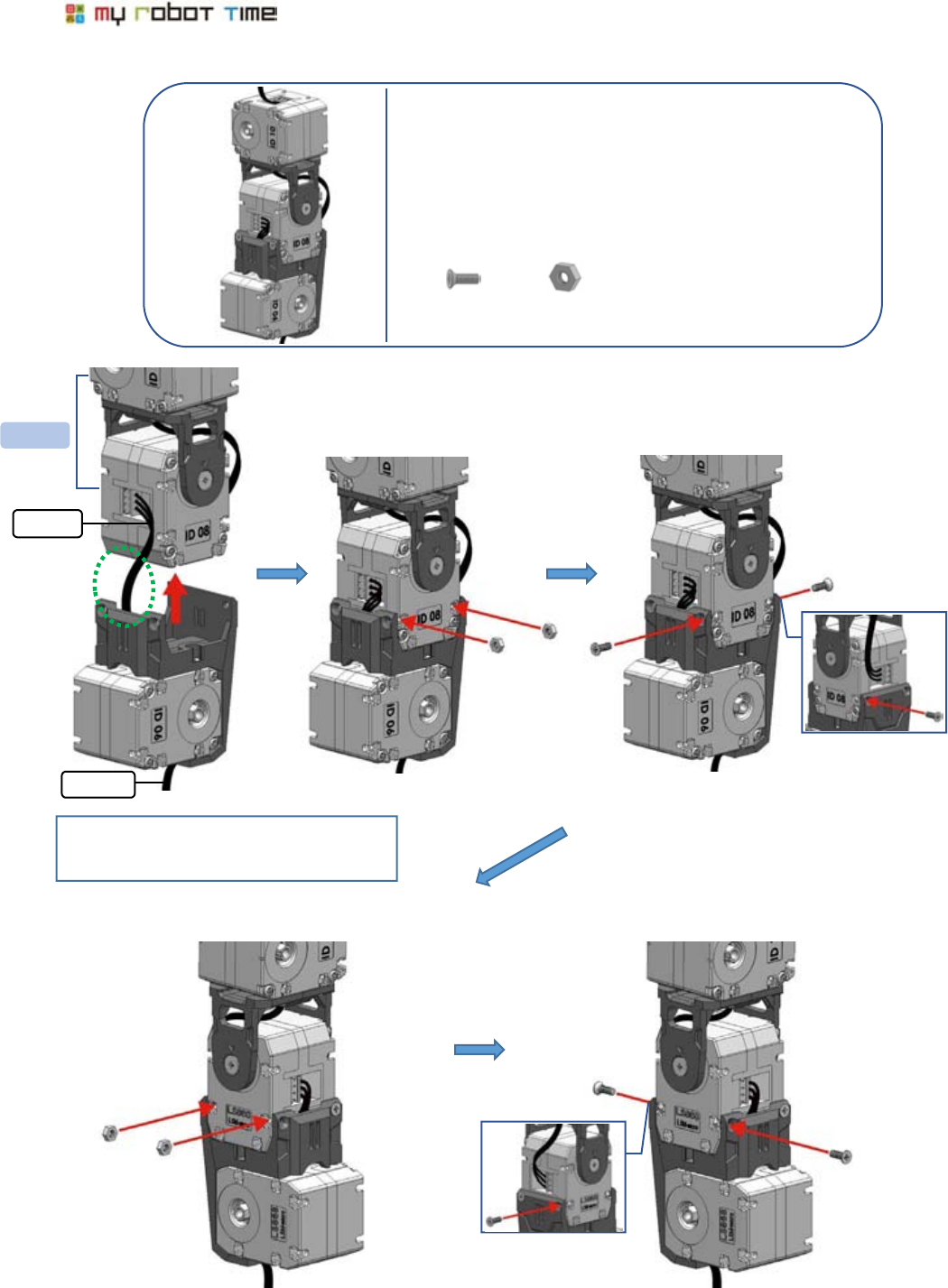
PART1-4
CABLE_6
PART1-2
CABLE_10
①
②
Please refer to No. 1picture,
neaten cable_6 first.
NUT X4
F6 X4
LINE-Core M
19
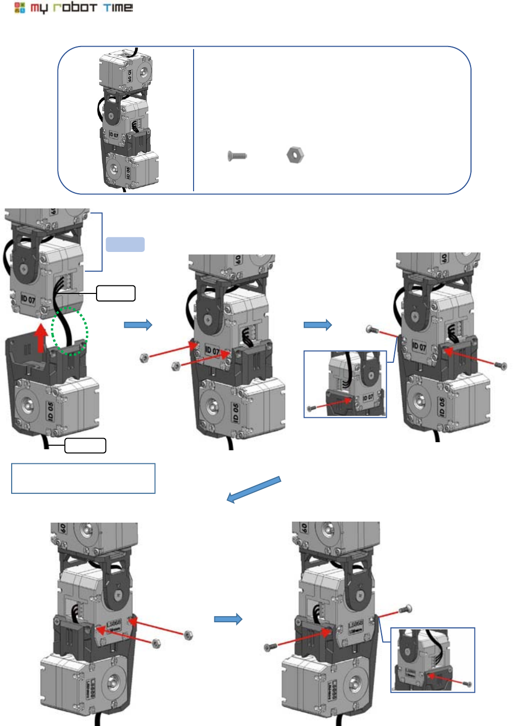
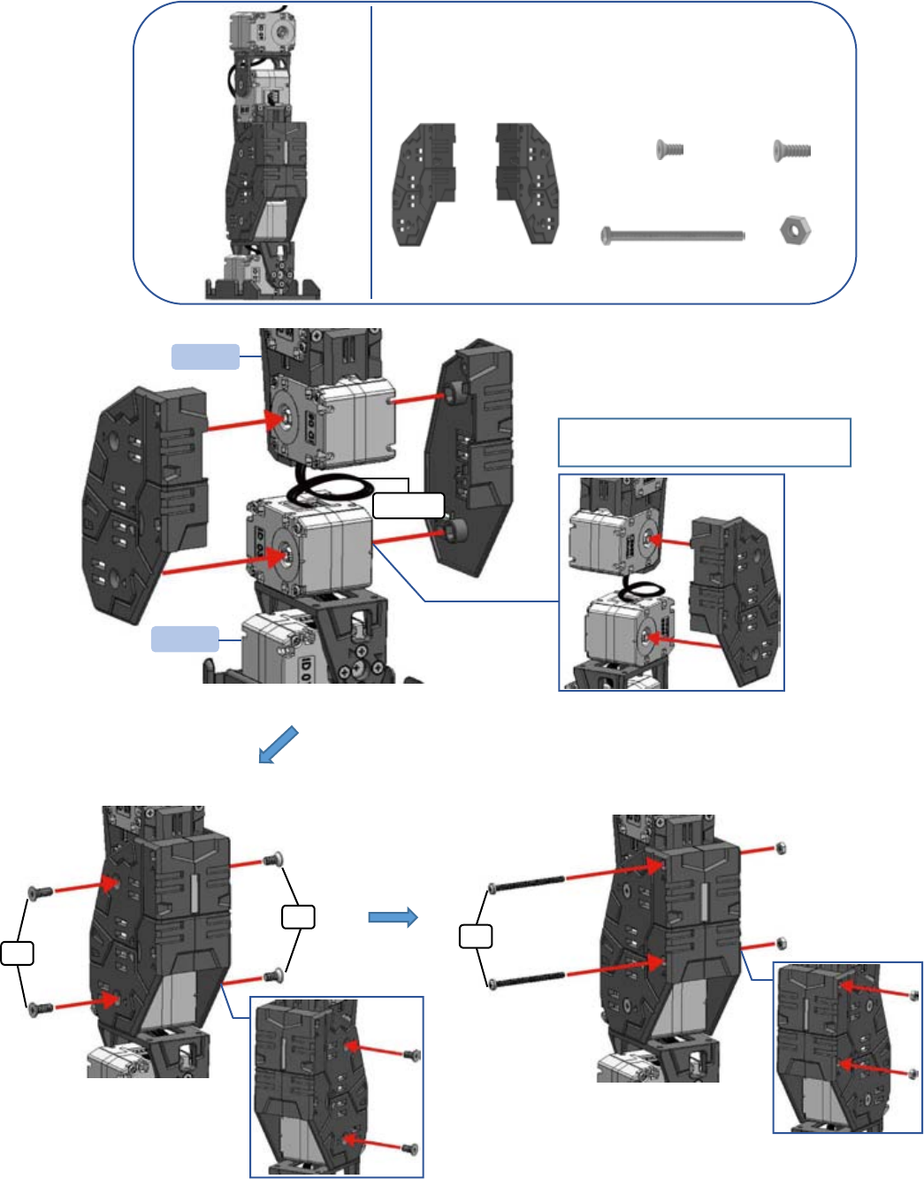
PART1-5
PART1-6
LSM-micro ID0
Please notice the groove in LSM-Micro
(up side)
LSM-micro ID0
slope side
NUT X4
F6 X4
LSM-micro(ID03) X1
ANKLE X1
NUT X4
F6 X4
LSM-micro(ID01) X1
FOOT X1
20
PART1-7
PART1-8
CABLE_6
PART1-5
①
②
HORN X2
NUT X8
3F6 X1
3F8 X1
F6 X8
CABLE_6 X1
LINE-Core M
21
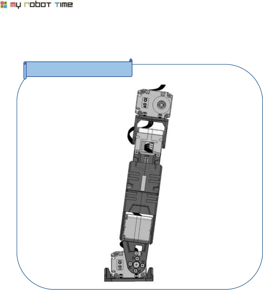
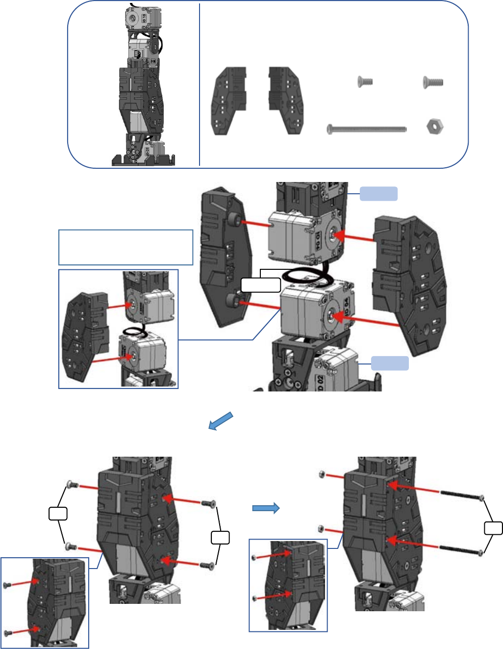
PART1-9
NUT X2
B30 X2
SHIN-R X1
SHIN-L X1
3F6 X2
3F8 X2
3F6
3F8
B30
PART1-4
PART1-8
CABLE_10
Please rotate the cable _10 one
circle before neaten.
①
②
②
①
②
22
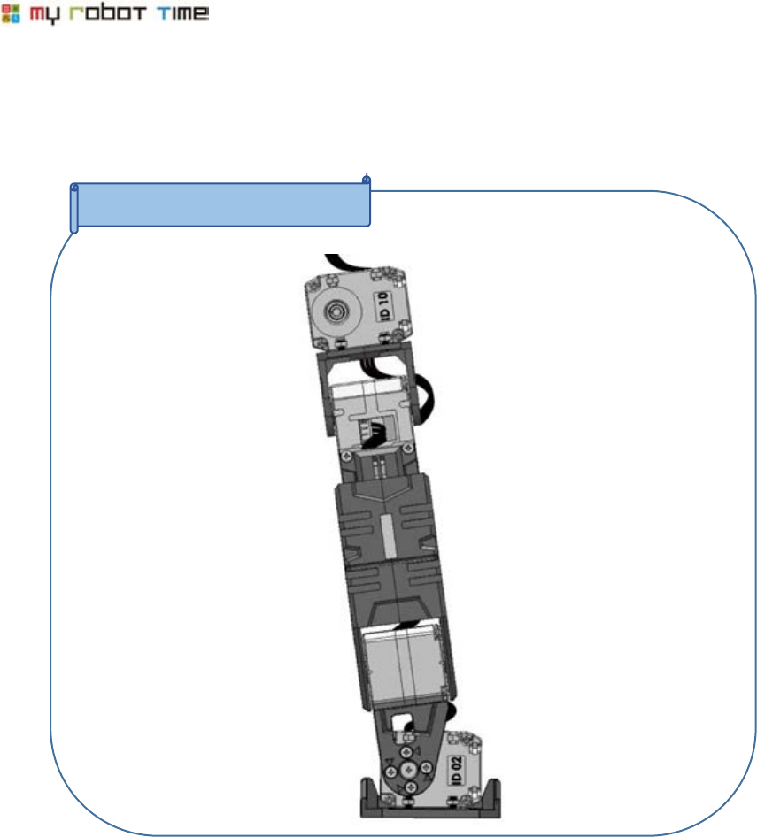
PART1 RIGHT LEG completed
LINE-Core M
23
PART2 LEFT LEG
PART2-1
3F6
3F8
LSM-micro ID0
Please notice the groove in
LSM-Micro (Up side)
3F6 X1
LSM-micro(ID08) X
3F8 X1
PELVIS X2
24
PART2-2
LSM-micro ID1
CABLE_8
CABLE_16
CABLE_8
Please notice the groove in LSM-Micro
(Up side).
Please turn the
pelvis backward
90 degree.
Please notice the groove in LSM-Micro (Up side)
Please turn the
previs backward
90 degree.
F6 X4
CABLE_8 X1
NUT X4
LSM-micro(ID10) X
CABLE_16 X1
LINE-Core M
25
PART2-3
CABLE_1
CABLE_6
LSM-micro ID0
CABLE_6
Please notice the groove
in LSM-Micro (Up side)
①
②
LSM-micro(ID06) X1
NUT X4
CABLE_6 X1
CABLE_10 X
F6 X4
THIGH X1
26
PART2-4
PART2-2
CABLE_6
CABLE_10
①
②
Please refer to No.1 picture, neaten
cable.6 first.
NUT X4
F6 X4
LINE-Core M
27
PART2-5
PART2-6
LSM-micro ID0
Please notice the groove in LSM-Micro (Up side)
LSM-micro ID0
slope side
NUT X4
F6 X4
LSM-micro(ID04) X1
ANKLE X1
NUT X4
F6 X4
LSM-micro(ID02) X1
FOOT X1
28
PART2-7
PART2-8
CABLE_6
PART2-5
①
②
HORN X2
NUT X8
3F6 X1
3F8 X1
F6 X8
CABLE_6 X1
LINE-Core M
29
PART2-9
NUT X2
B30 X2
SHIN-R X1
SHIN-L X1
3F6 X2
3F8 X2
3F6
3F8
B30
PART2-4
CABLE_10
PART2-8
Please rotate cable_10 one
circle before neaten.
①
②
①
②
②
30
PART2 LEFT LEG Completed
LINE-Core M
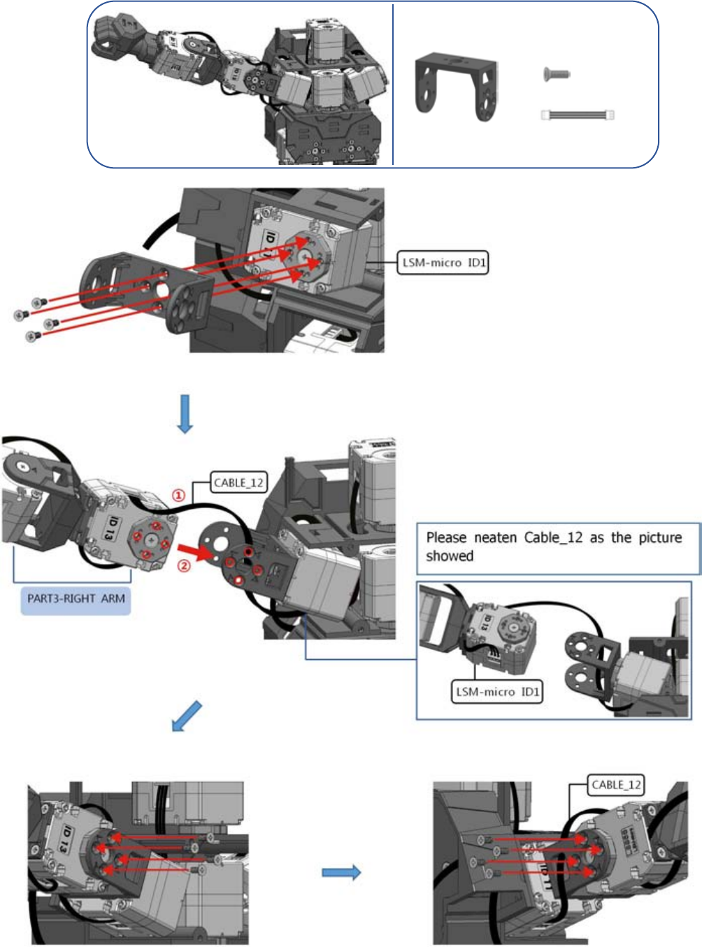
31
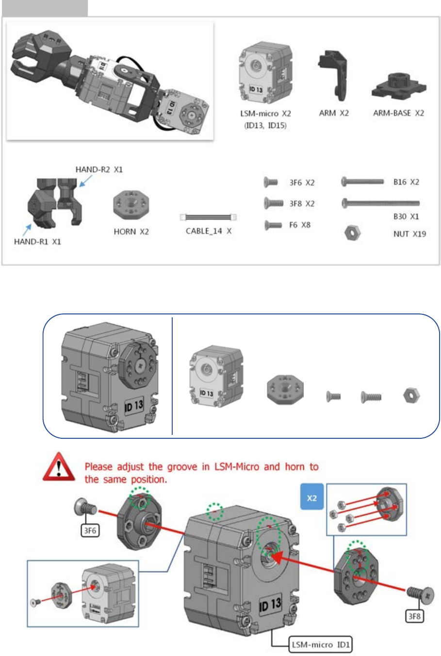
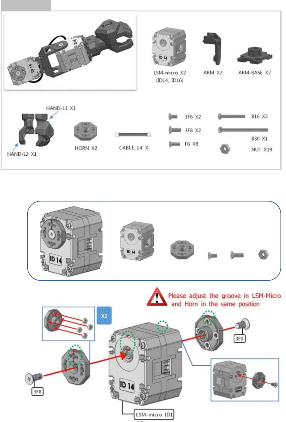
PART3 RIGHT ARM
PART3-1
LSM-micro(ID13) X1
HORN X2
3F6 X1
NUT X8
3F8 X1
32
PART3-2
PART3-3
3F6
3F8
Please Keep the groove in LSM-Micro
up side.
LSM-micro ID1
CABLE_14
It will be more convenient to neaten Cable _14 and ARM-Base
first, then assemble nut and bolt.
3F6 X1
LSM-micro(ID15) X
ARM X2
3F8 X1
CABLE_14 X1
F6 X4
ARM-BASE X1
NUT X
4
LINE-Core M
33
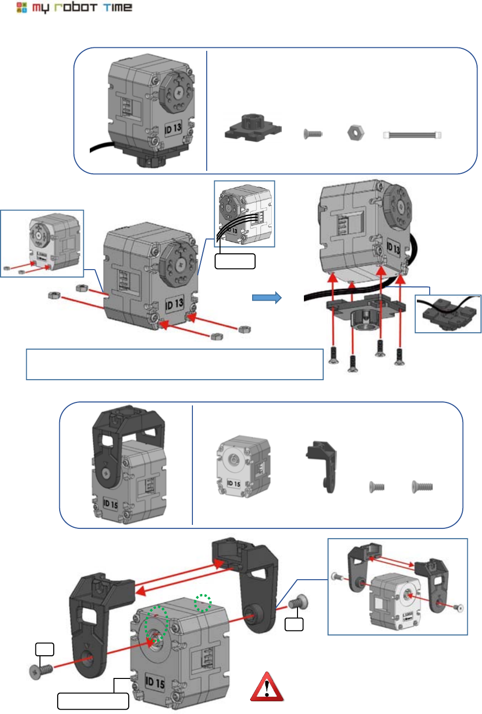
PART3-4
PART3-5
NUT X2
B16 X1
B30 X1
HAND-R2 X1
HAND-R1 X1
PART3-4
B30
B16
①
②
③
①
②
Please inset the nuts into Hand-R2
F6 X4
NUT X4
ARM-BASE X1
34
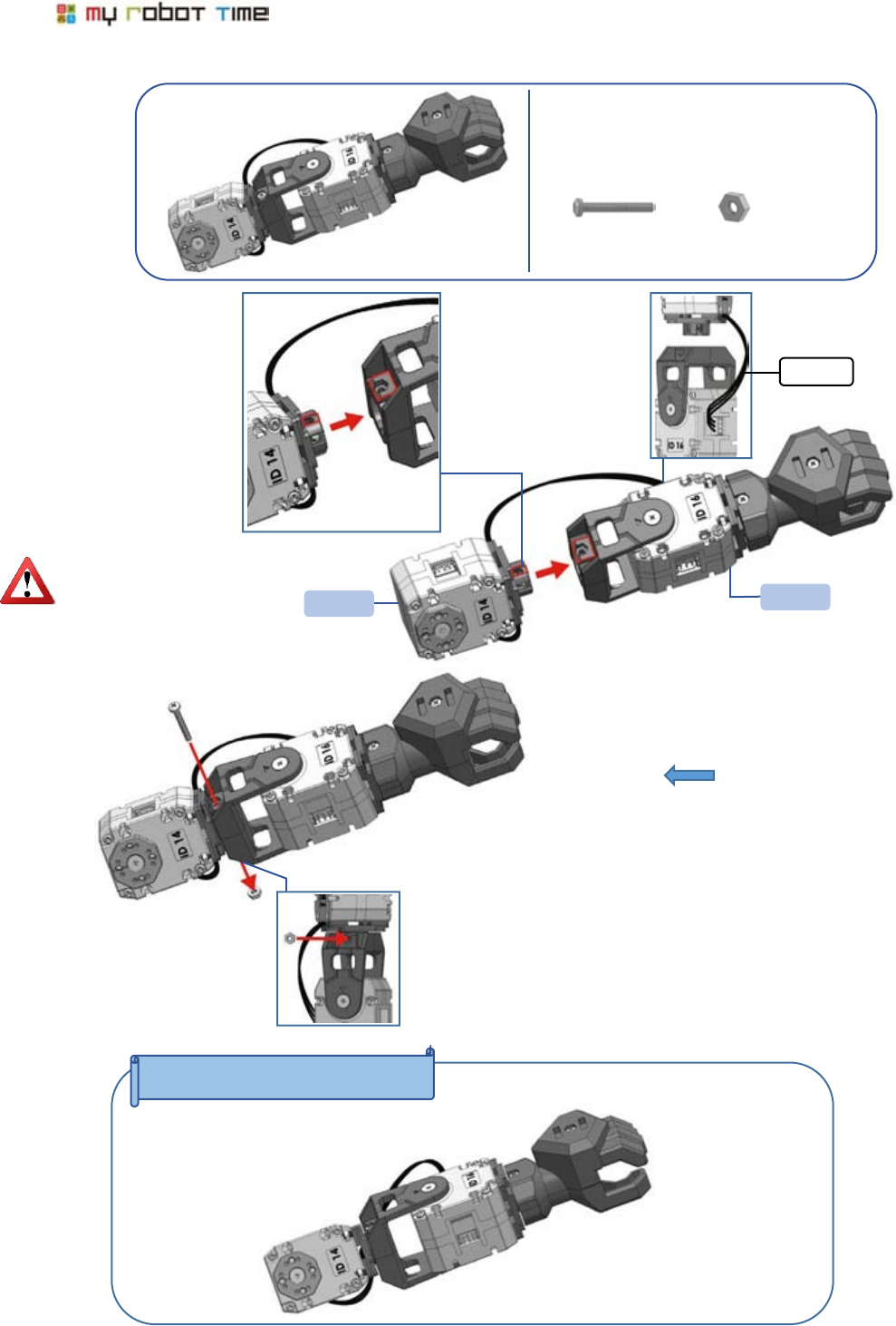
PART3-6
NUT X1
B16 X1
Please notice the direction
when assemble PART3-2
and PART3-5.
PART3 RIGHT ARM Completed
CABLE_14
PART3-2
PART3-5
①
②
①
②
LINE-Core M
35
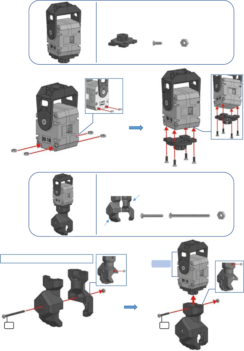
PART4 LEFT ARM
PART4-1
LSM-micro(ID14) X1
HORN X2
3F6 X1
NUT X8
3F8 X1
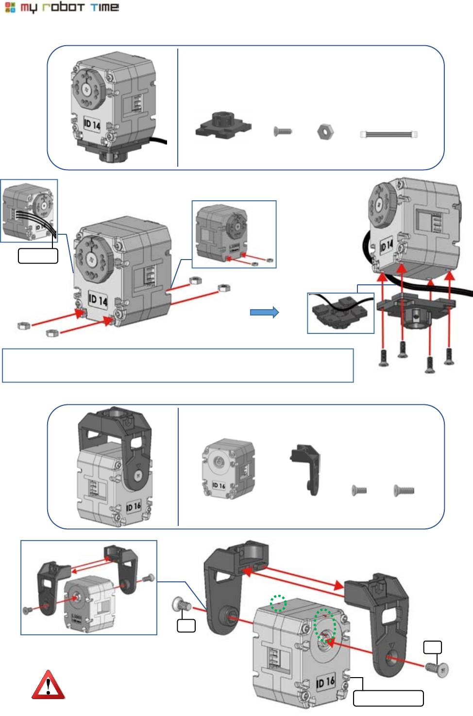
36
PART4-2
PART4-3
3F6
3F8
Please keep the groove in LSM-Micro
Up side.
LSM-micro ID1
CABLE_14
It will be more convenient to neaten Cable_14 and Arm-base first, then a
ssemble nut and screw.
3F6 X1
LSM-micro(ID16) X
ARM X2
3F8 X1
CABLE_14 X1
F6 X4
ARM-BASE X1
NUT X
4
LINE-Core M
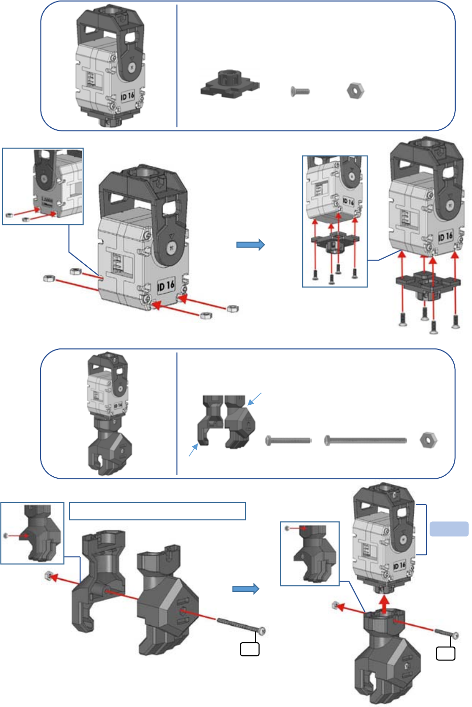
37
PART4-4
PART4-5
PART4-4
B30
B16
①
②
③
Please insert the nut into Hand-L2
①
②
NUT X2
B16 X1
B30 X1
HAND-L2 X1
HAND-L1 X1
F6 X4
NUT X4
ARM-BASE X1
38
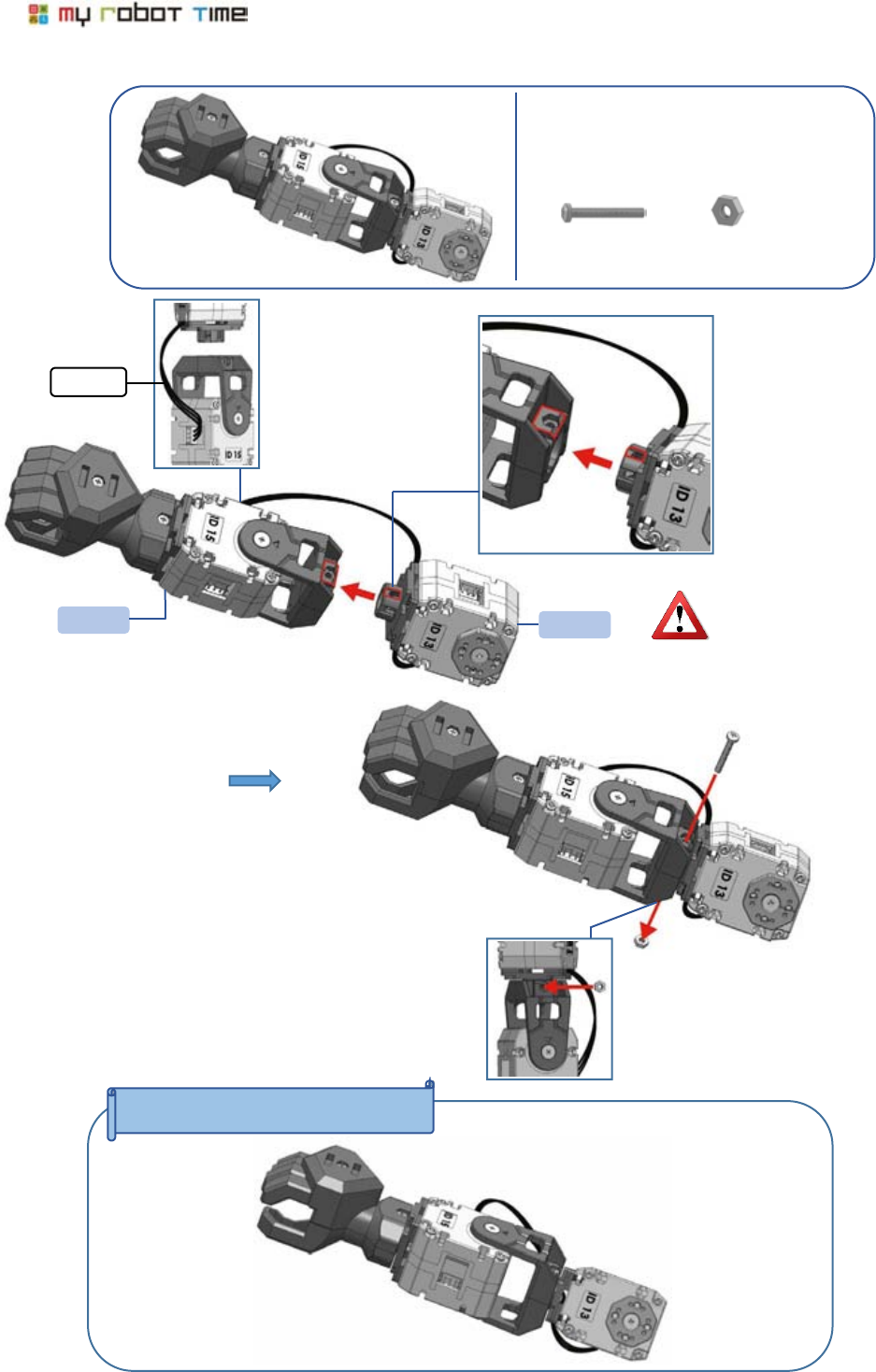
PART4-6
PART4 LEFT ARM Completed
CABLE_14
PART4-5
PART4-2
Please notice the direction
of Part4-2 and Part4-5 when
assembling.
①
②
①
②
NUT X1
B16 X1
LINE-Core M
39
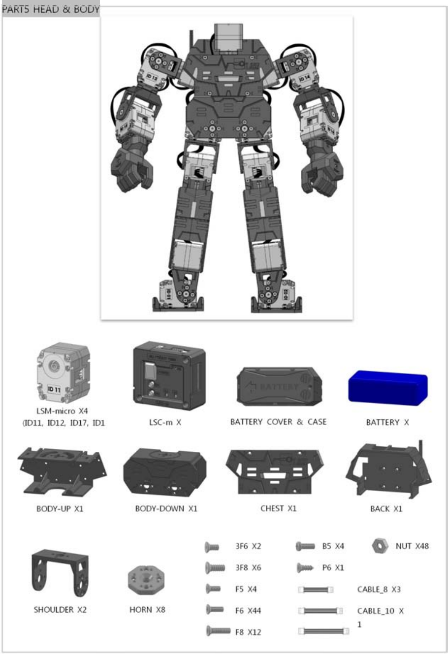
PART5 HEAD & BODY
40
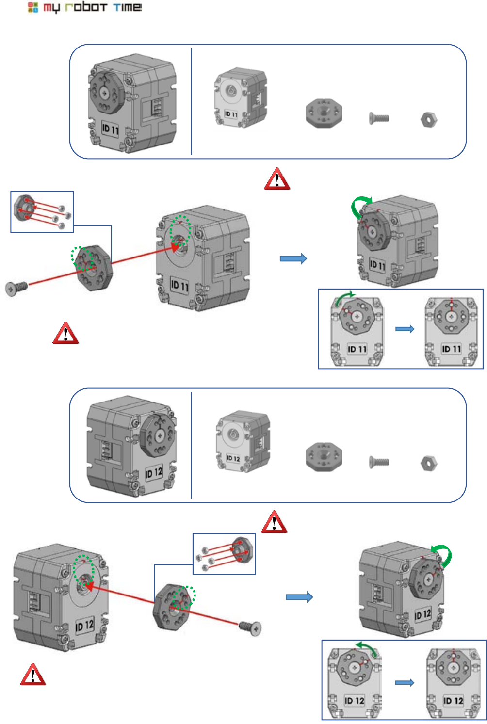
PART5-1
PART5-2
LSM-micro(ID11) X1
HORN X1
3F8 X1
NUT X4
LSM-micro(ID12) X1
HORN X1
3F8 X1
NUT X4
Please keep the groove in LSM-Micro
and Horn the same position.(up side)
Please put the horn spinning 60 degree
to right side.Please keep the groove in
LSM-Micro and horn the same position.
(up side)
60°
Please keep the groove in LSM-Micro and horn the
same position.(up side)
Please put the horn spinning 60 degree to right
side.Please keep the groove in LSM-Micro and
horn the same position.(up side)
60°
LINE-Core M
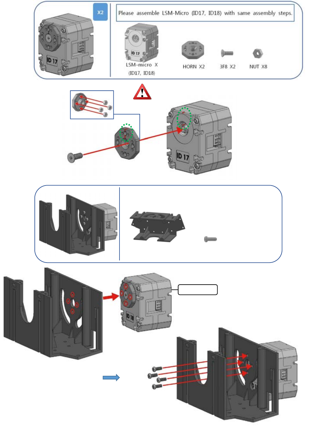
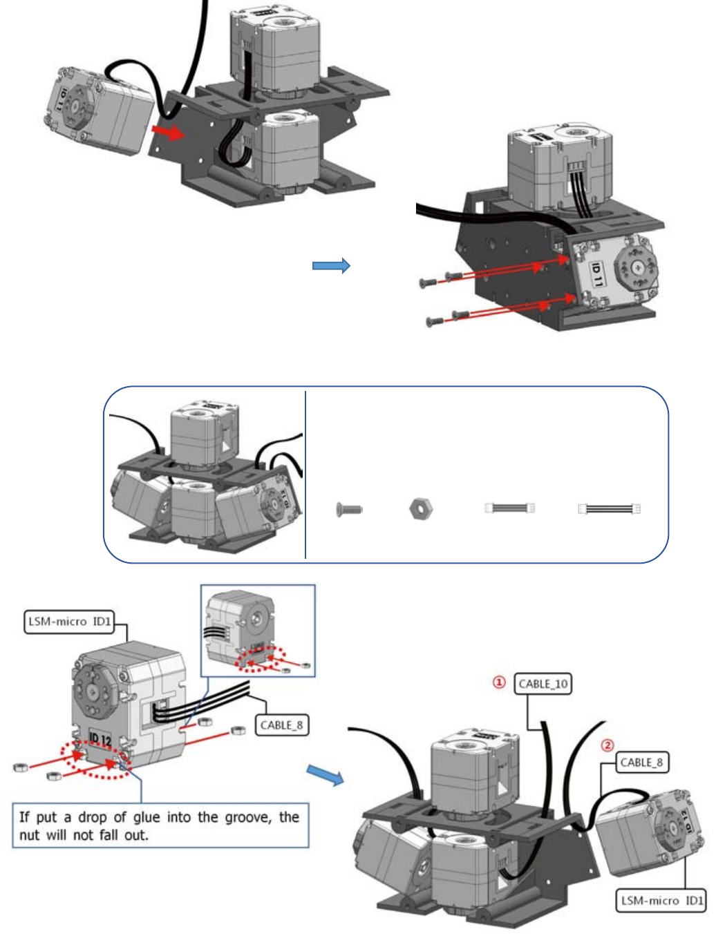
41
PART5-3
PART5-4
Please keep the groove in LSM-Micro and horn the
same position.(up side)
LSM-micro ID1
B5 X4
BODY-UP X1
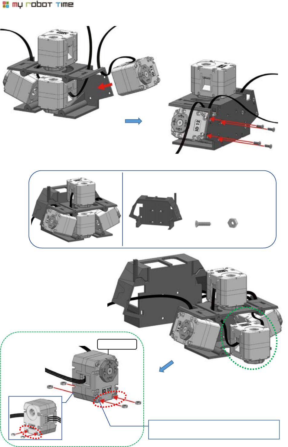
42
PART5-5
PART5-6
LSM-micro ID18
CABLE_8
LSM-micro ID17
Please notice the direction when assemle
LSM-Micro(ID17) and LSM-Micro(ID 18).
Assemble the back port of LSM-Micro to
up side and the ID port of LSM-Micro to
down side
The screw in LSM-Micro(ID17) and body up
will finish in Part5-8
CABLE_8 X1
CABLE_8 X1
F6 X4
NUT X4
LINE-Core M
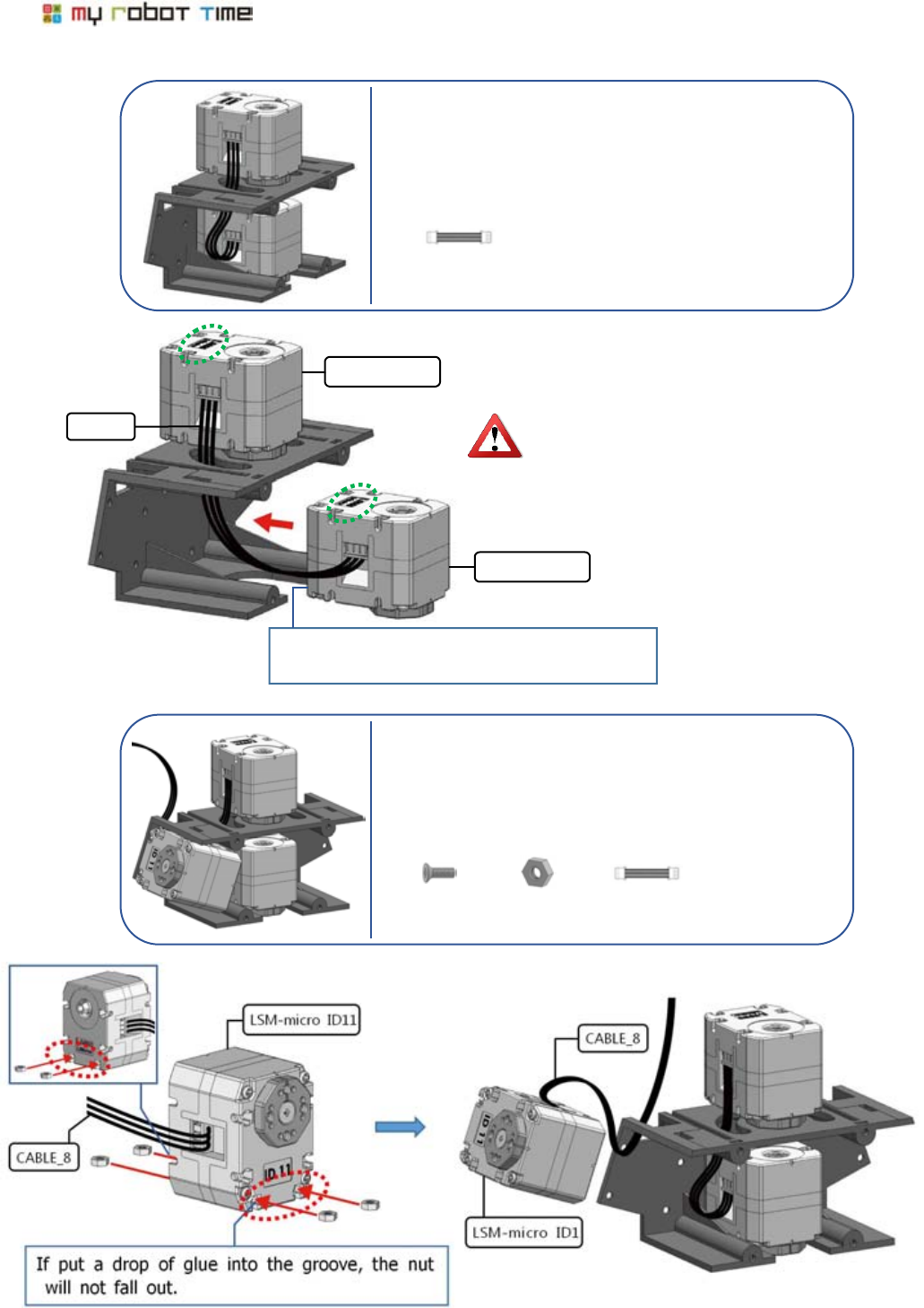
43
PART5-7
CABLE_8 X1
F6 X4
NUT X4
CABLE_10 X
1
44
PART5-8
If put a drop of glue into the groove, the
nut will not fall out.
LSM-micro ID1
①
②
F8 X4
NUT X4
BACK X1
LINE-Core M
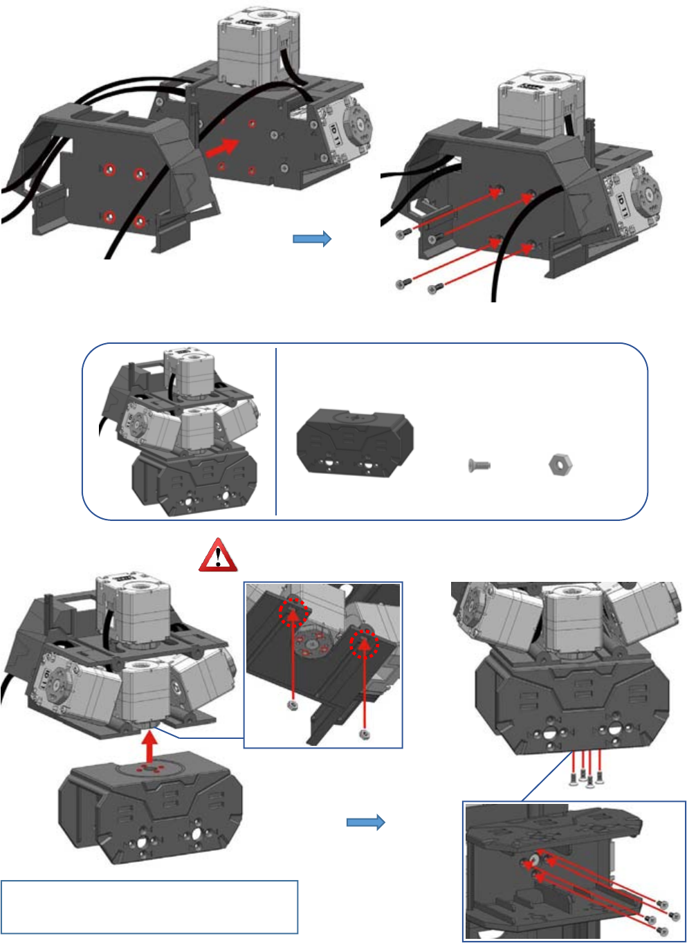
45
PART5-9
F5 X4
BODY-DOWN X1
NUT X2
If put a drop of glue into the groove, the
nut will not fall out.
Please insert the nut into Body-up first.
①
②
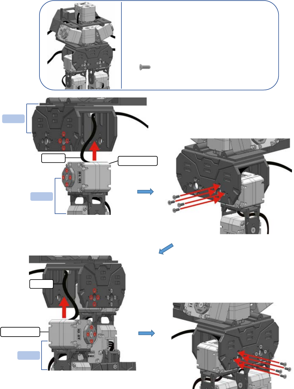
46
PART5-10
PART5-11
HORN X2
3F6 X1
NUT X8
3F8 X1
HORN X2
3F6 X1
NUT X8
3F8 X1
LINE-Core M
47
PART5-12
F6 X8
PART5-9
CABLE_16
LSM-micro ID10
PART5-11
CABLE_16
LSM-micro ID0
PART5-10
①
②
①
②
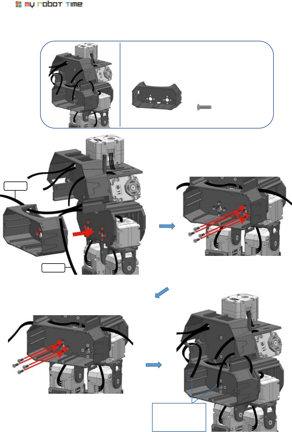
48
PART5-13
CABLE_16
CABLE_16
Please neaten
Cable-16 as the
picture showed.
①
②
①
F8 X8
BATTERY CASE X
LINE-Core M
49
PART5-14
SHOULDER X1
CABLE_12 X
1
F6 X12
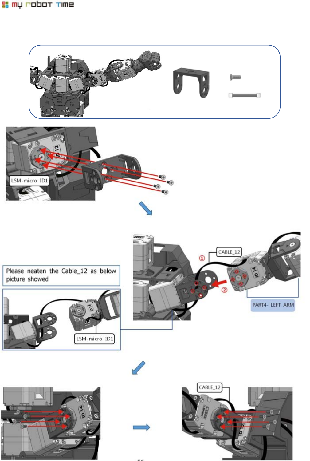
50
PART5-15
SHOULDER X1
CABLE_12 X
1
F6 X12
LINE-Core M
51
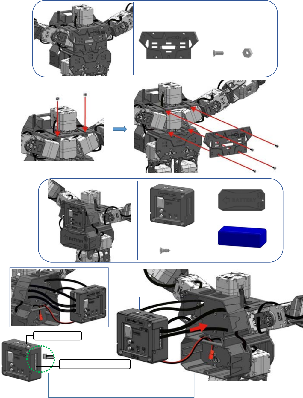
PART5-16
PART5-17
PC Special port
LSM-Micro connect port
There is 6 connect ports in left and right side of
LSM-Micro. The cable can connect to any port in
LSM-Micro( PC port can not)
①
②
BATTERY X
LSC-m X1
BATTERY COVER X
P6 X1
NUT X2
CHEST X1
F6 X4
52
PART5 HEAD & BODY Completed
Please connect the wire of LSM-M and
battery first. Please connect the wire as
left side picture showed
①
②
Red
Black
Red
Black
LINE-Core M
53
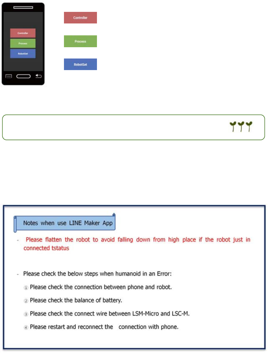
8. The introduction of LINE Maker App
User can use LINE Maker App to control and program the robot.
-you can scan the barcode which in the last page of book to download
LINE Maker App.
Can control the robot as a remote controller
Can program the robot motion
Can adjust zero degree and check the robot
※LINE-Core M already included basic motions, can compile other
favorite motions to humanoid on LINE Maker APP.
54
9. How to confirm the basic motion of LINE-Core M?
Except the basic motion, Line-Core M also offer Boxing, Soccer,Dance and Mission modes. In order to
let LINE-Core m finish the mission more better, We need confirm the basic motion and adjust zero
degree.
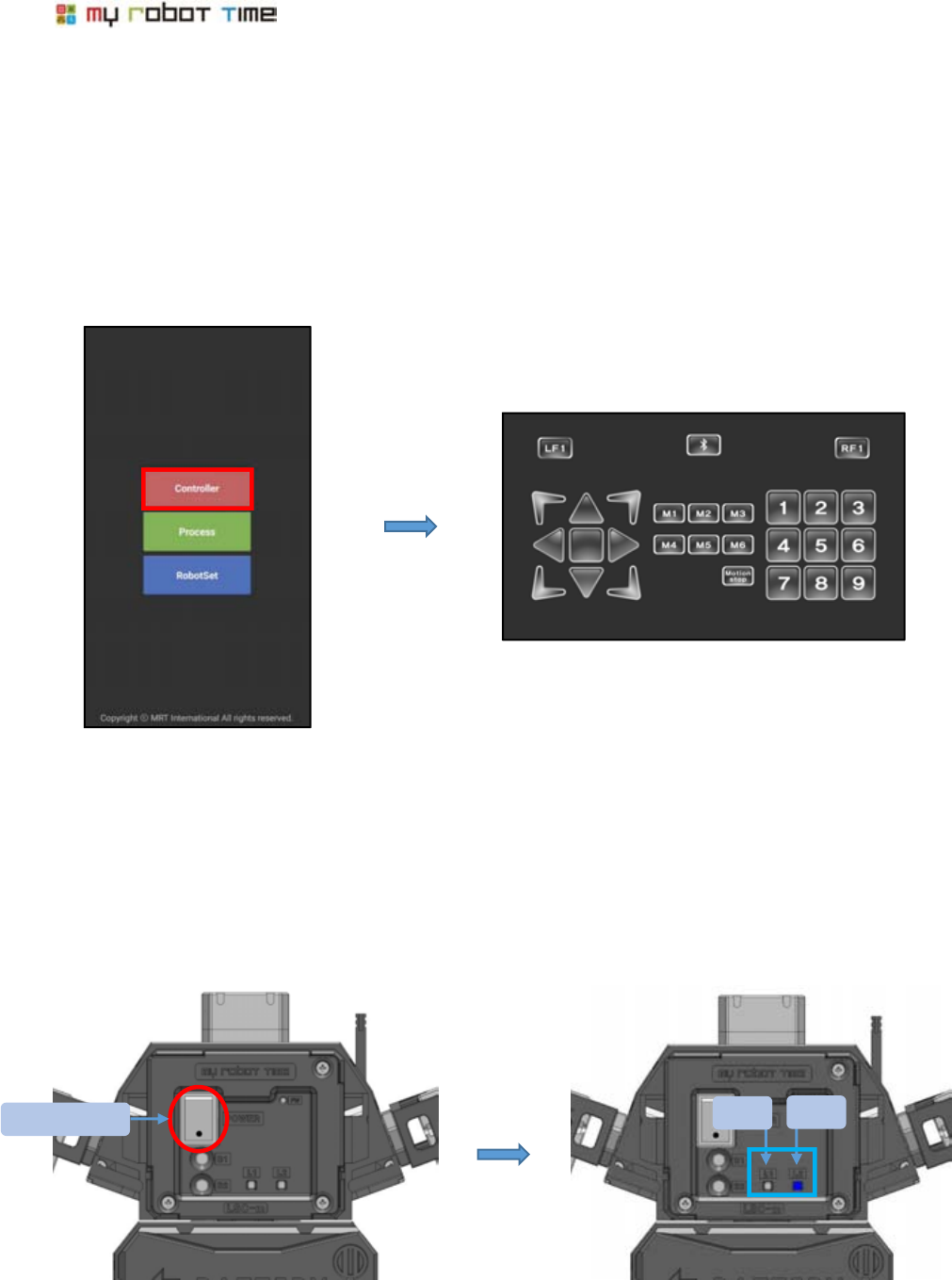
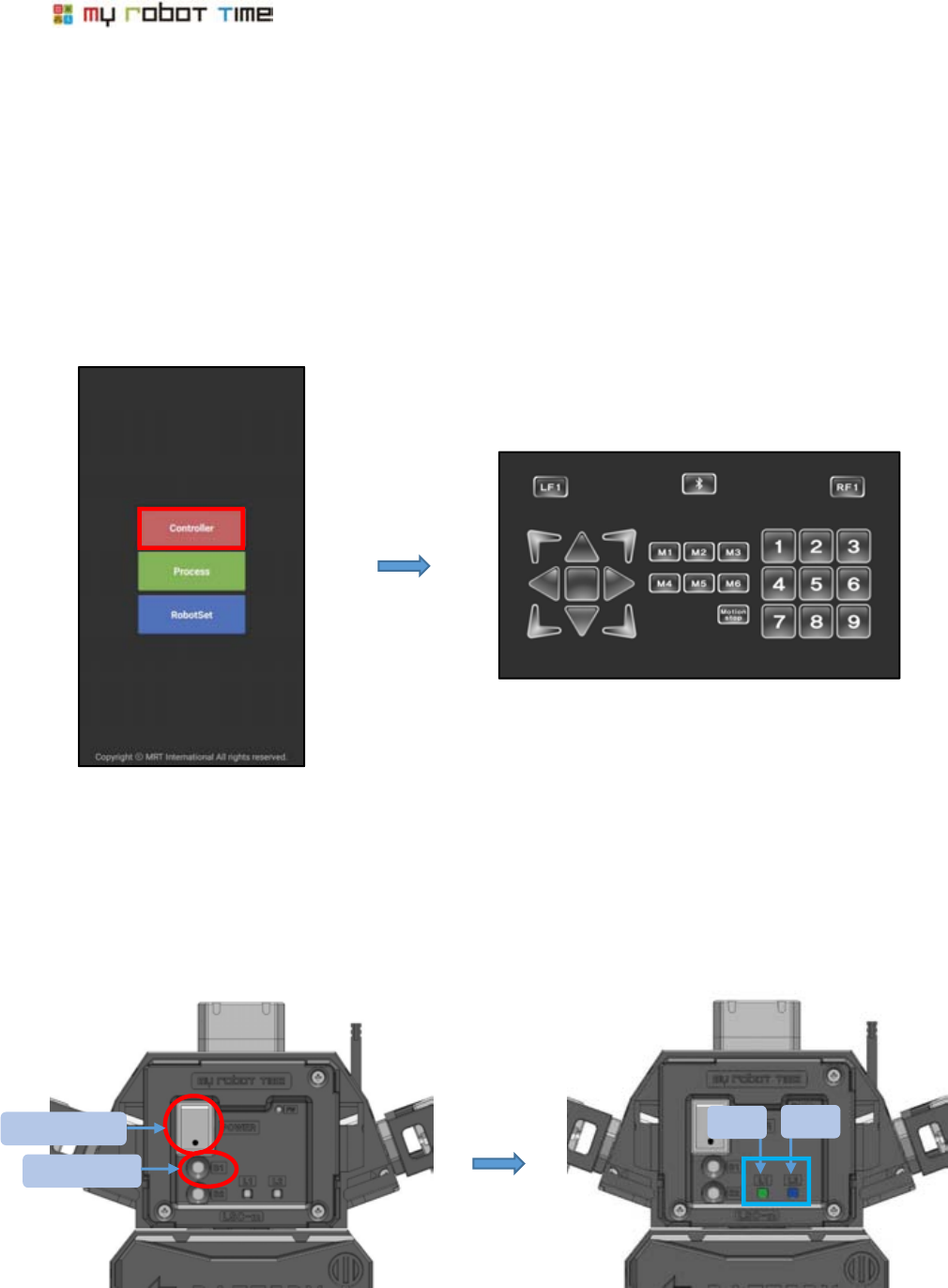
1. Run LINE Maker App, choose controller. It will enter control interface.
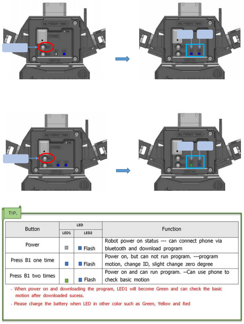
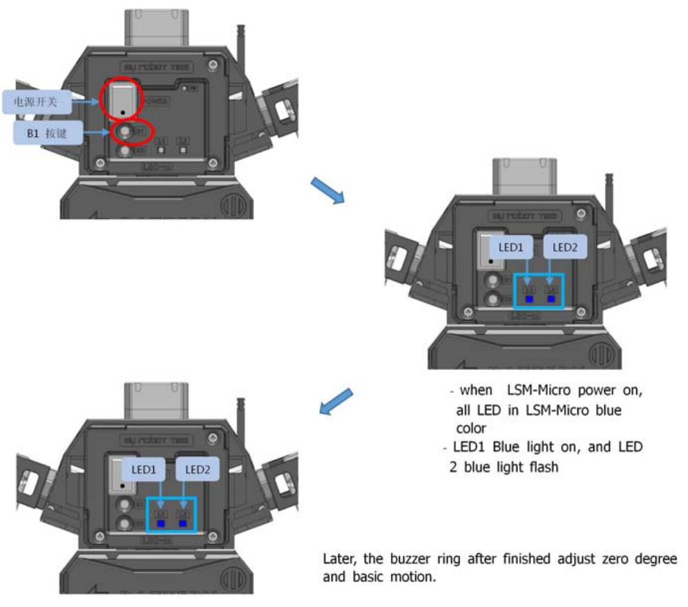
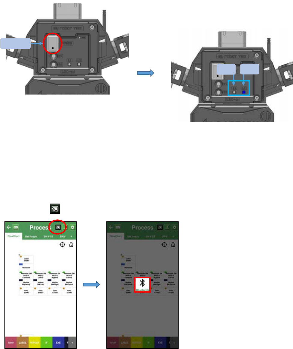
2. Please turn on the power before we connect the robot with phone. -The buzzer and LED2 blue
light will flash when opened.
Power switch
LED 2 will flash blue light with buzzer sensor
LED1
LED2
LINE-Core M
55
3. Please press B1 button. -- when power on, LSM-Micro LED1 blue light will on, LED2 blue
light will flash.
4. Please press B1 button again, -LED1 will become green light and LED2 will become blue light and
flash.
Button
LED
Function
LED1
LED2
Power
Flash
Robot power on status --- can connect phone via
bluetooth and download program
Press B1 one time
Flash
Power on, but can not run program. ---program
motion, change ID, slight change zero degree
Press B1 two times
Flash
Power on and can run program. --Can use phone to
check basic motion
LED 1 blue light on , LED 2 blue light flash
B1 button
LED1
LED2
LED1 green light on,LED2 blue light flash
B1 button
LED1
LED2
56
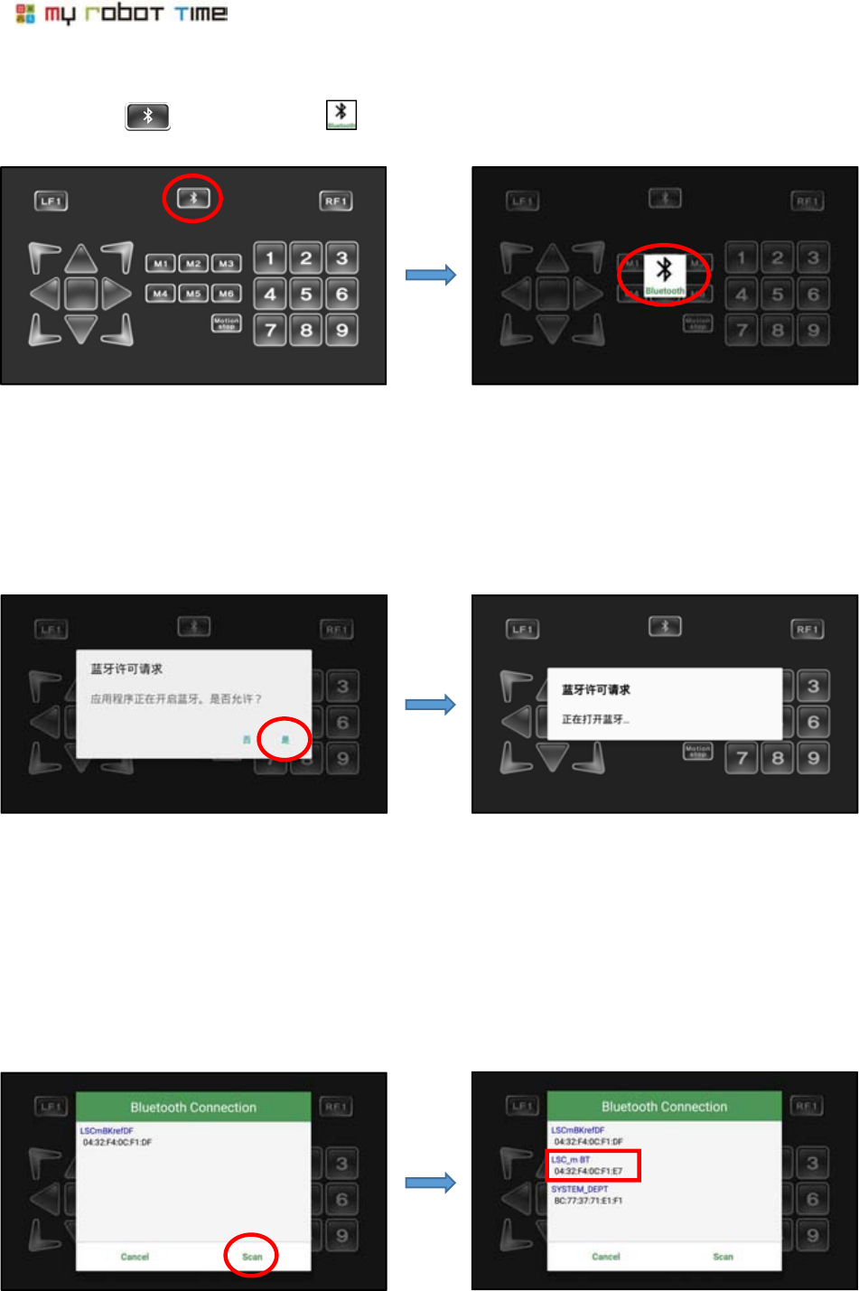
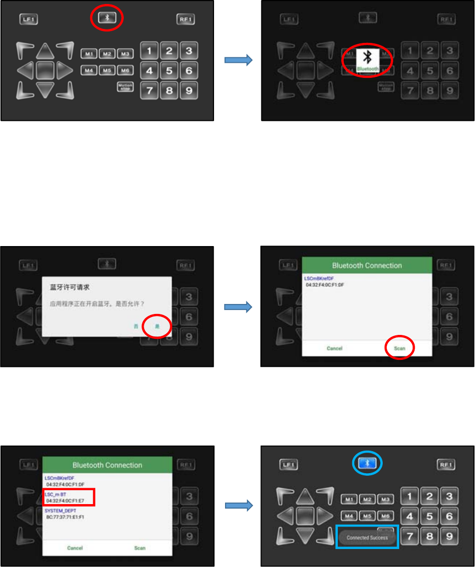
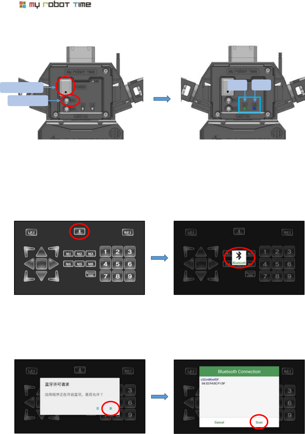
5.After press button, then press button.
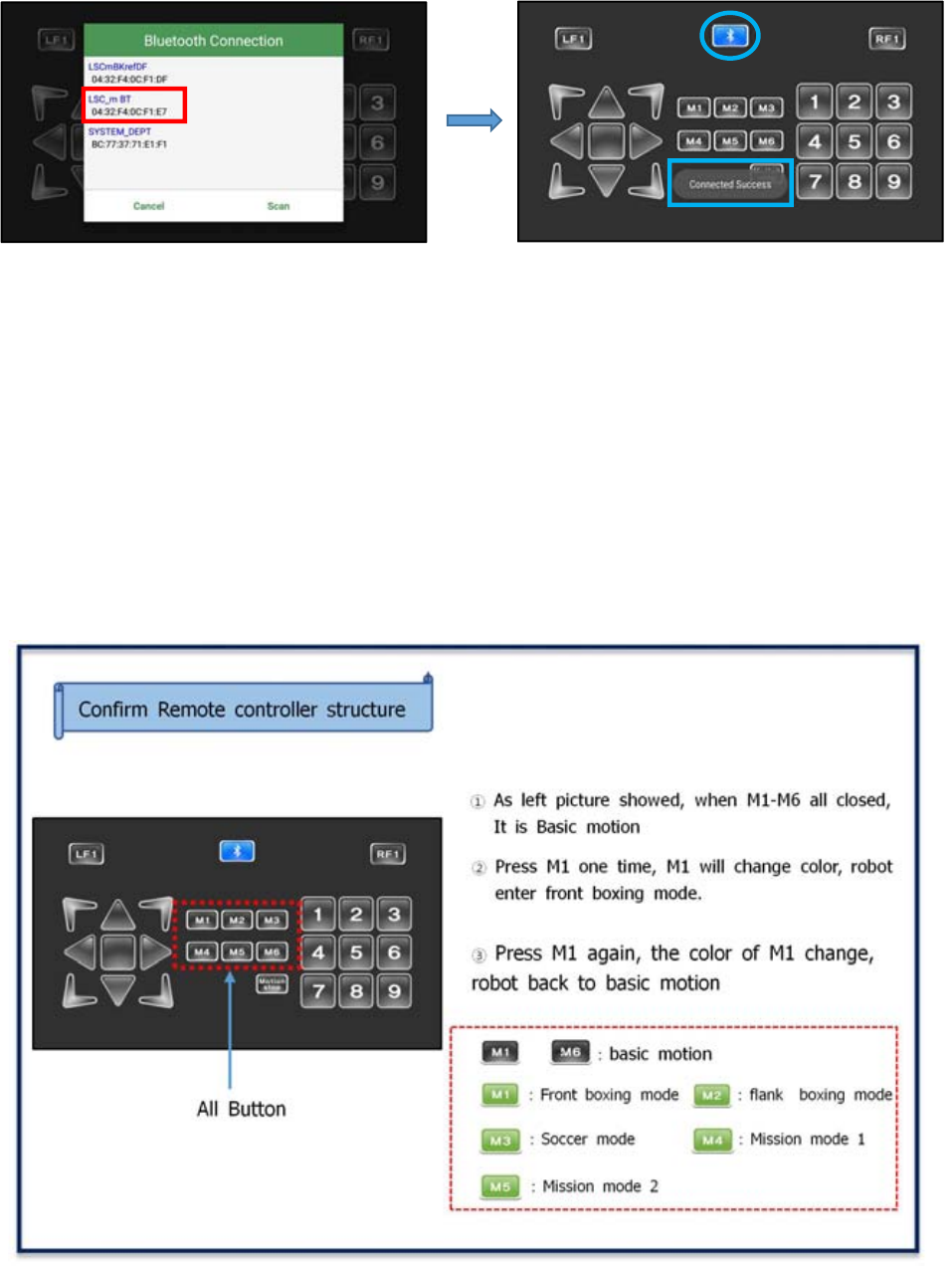
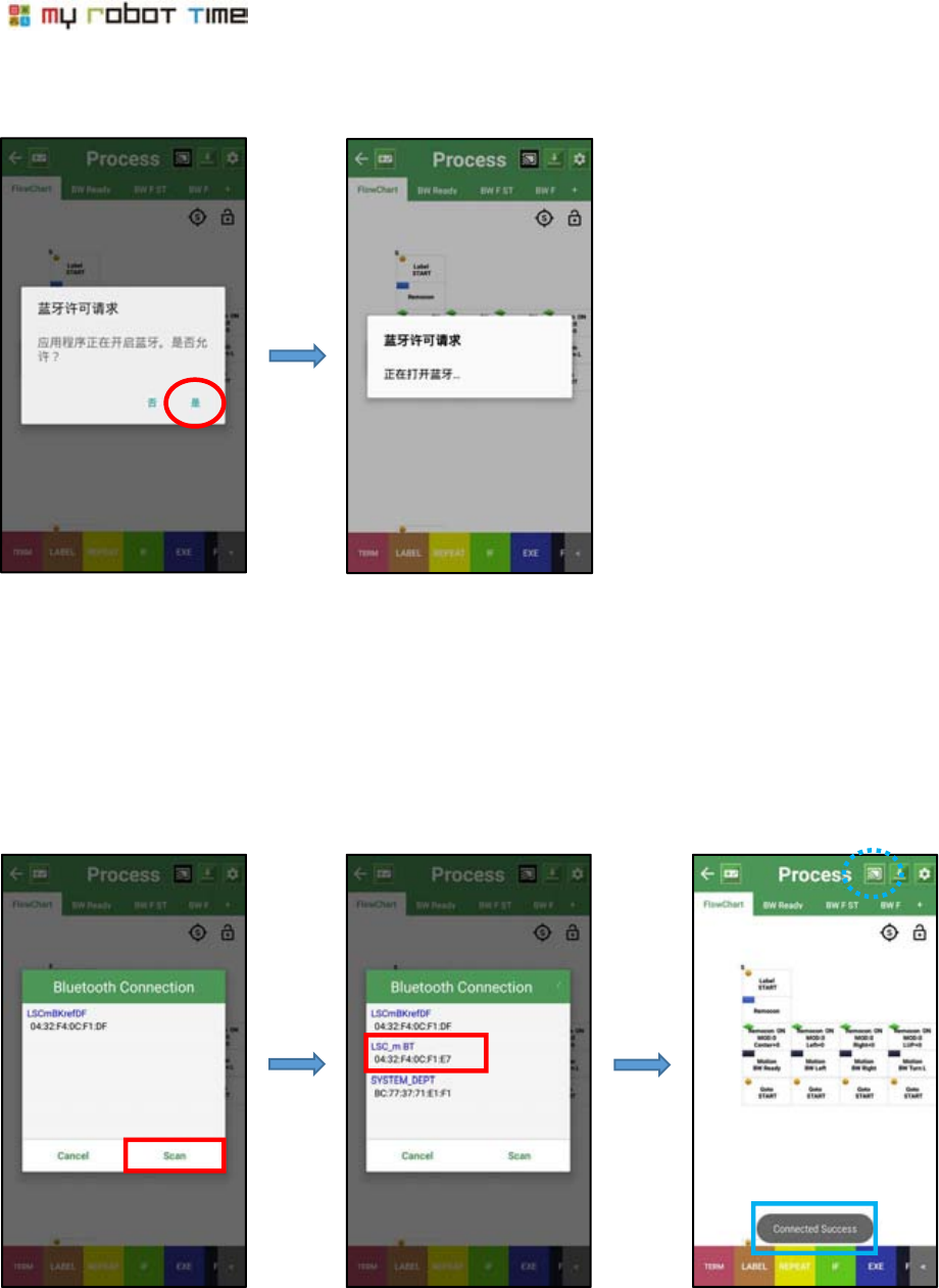
6. Please choose yes after the bluetooth interface appear in your phone.
7.Please click Scan, and choose robot ID.
※If the bluetooth in your phone is open. Then it will enter this interface as No7
LINE-Core M
57
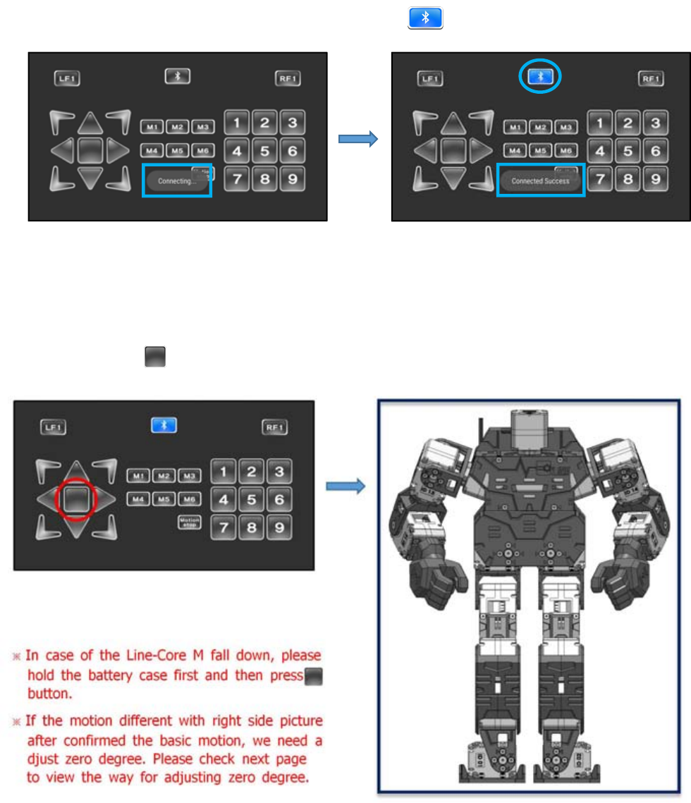
8. After connected. The bluetooth button will change color.
9. You can press to confirm LINE-Core M basic motion.
58
10. Adjust Zero degree
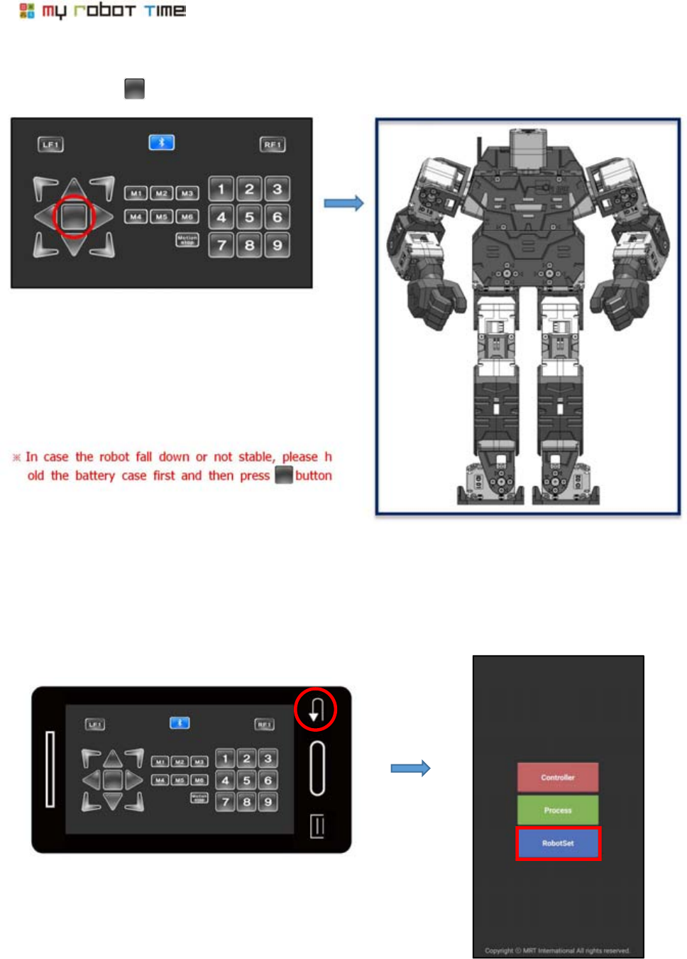
The motion our company provided is based on our humanoid robot, if the user changed the default
in LSM-Micro or assemble in different way, the robot may fall down or not stable when run the basic
motion, in this case, we need adjust zero degree.
10-1. Adjust zero degree and basic motion
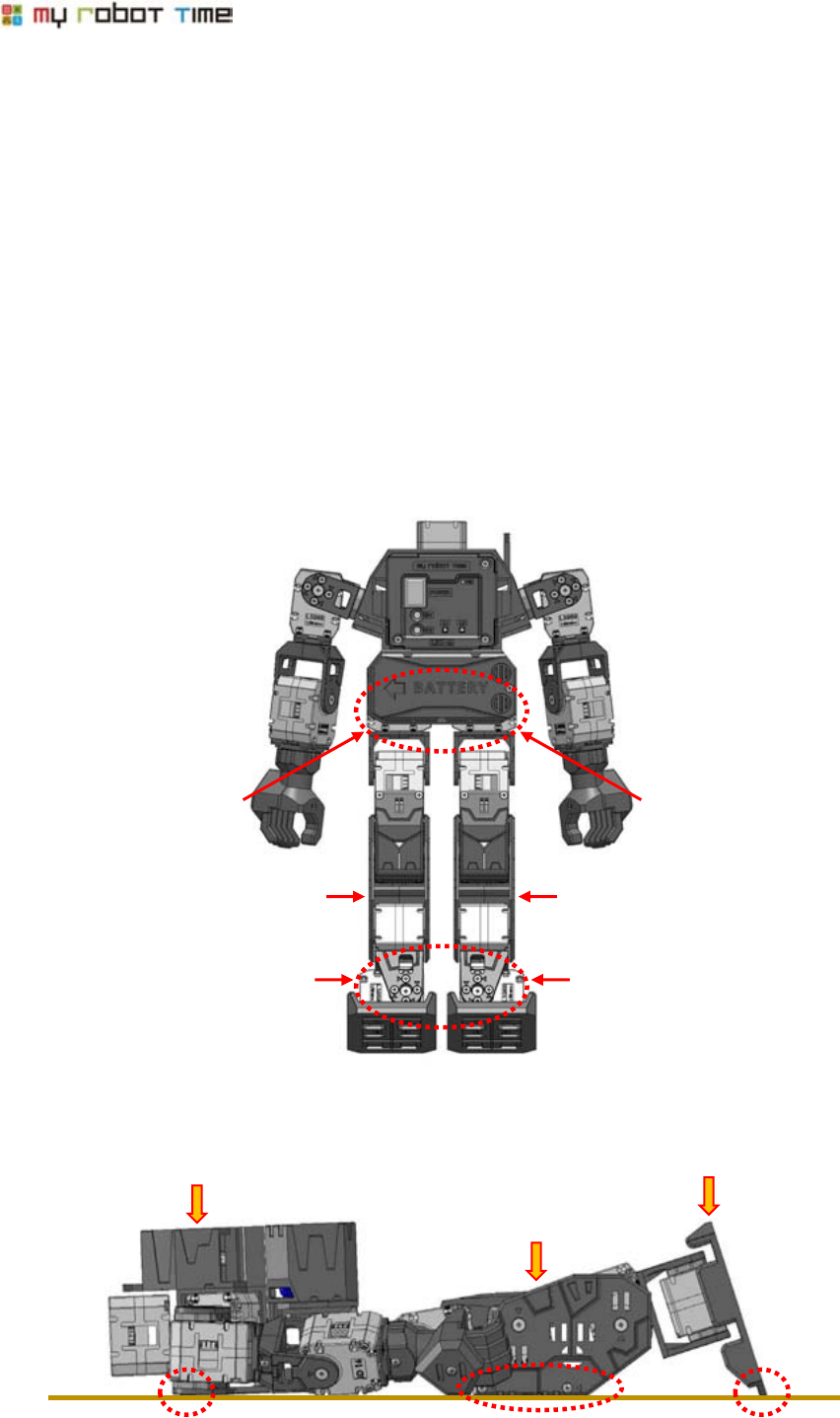
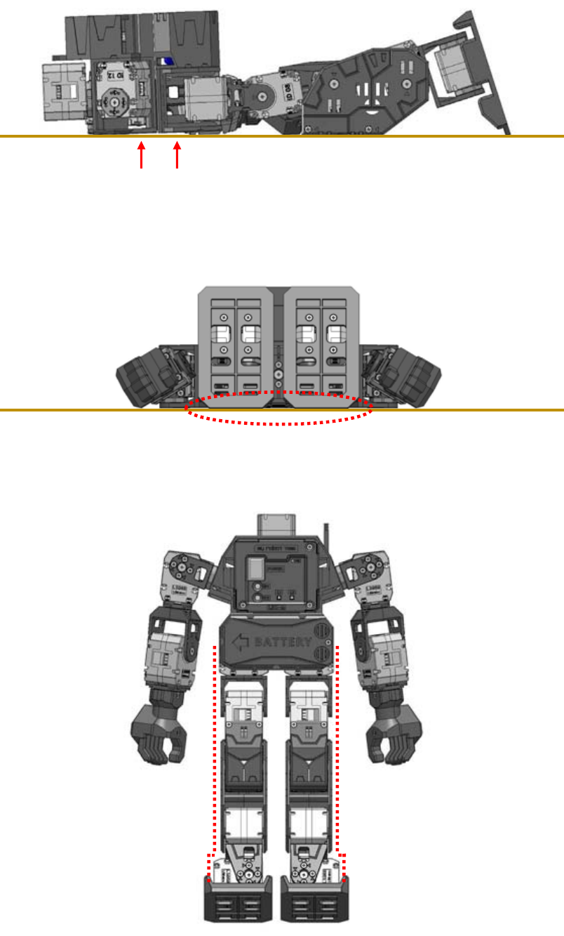
1. Close the power of LINE-Core M, please flatten the LINE-Core M and put on ground
2. ID01 and ID02, ID 09 and ID 10 is the axis which can move in LSM-Micro. We put the robot knee
and toe touch the ground. Please be gentle to put these part touch the ground.
①Press the knee, Let
this part touch the ground
②Press the toe, Let toe
touch the ground.
③Press the battery case
and let it touch the
ground
SHIN
SHIN
LSM-micro ID02
LSM-micro ID01
LSM-micro ID10
LSM-micro ID09
LINE-Core M
59
The following picture of Humanoid without arms is better to understand.
The chest and belly is not fully touched the ground.
Please place the toes in horizontal line.
The legs should unbend as below showed.
60
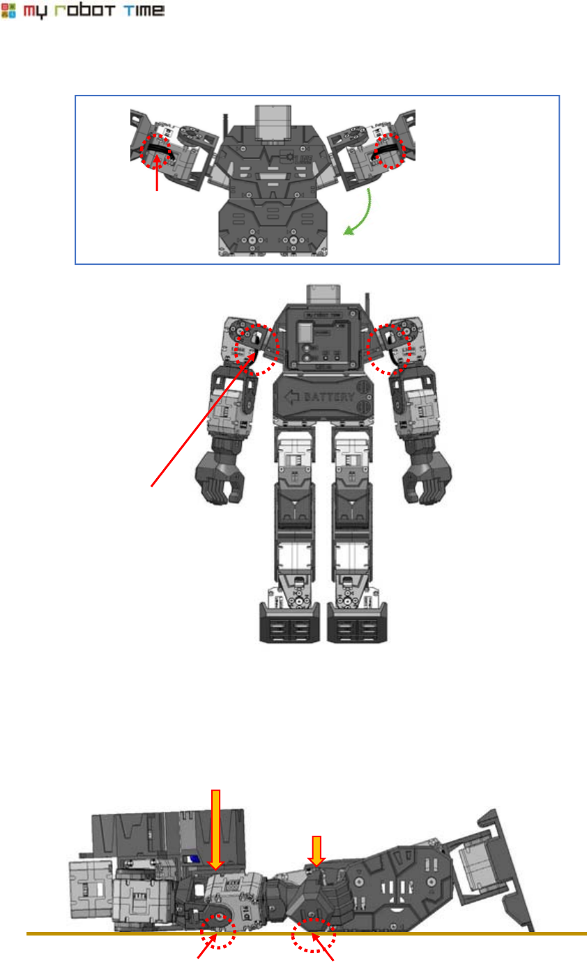
3. Please neaten the wire of LSM-Micro ID13 and ID14, then put the arms touch robot body.
4. Put LSD-Micro ID15 and ID16 and two hands touch the groud.
ID13 and ID14 of LSM-Micro will
entirely fit the shoulder
The wire in this part
should be flatted.
Do as the picture showed and
let the arm touch body.
②Press hand.
one side of LSM-Micro
ID15 and ID16 touch the
groud.
one side of hand touch the
ground
①Press LSM-Micro ID15 and ID 16
LINE-Core M
61
5. Press B1 first, then turn on the power, after power open, keep press B1 around 2 second.
62
10-2. Slight change on LSM-Micro Zero degree
You can do slight change on LSM-Micro in the following situation
▶The robot still not stable after adjusted zero degree and basic motion.
▶The robot can dance with suit, after equiped with suit, the center of gravity will change, at this
time, we just need adjust the part of LSM-Micro to find the center of gravity.
1. Run LINE Maker App, choose Controller, enter control interface.
2.Open robot power, press B1 two times.
LED 1 green light on, LED 2 blue light flash
Power switch
LED1
LED2
B1 button
LINE-Core M
63
3. Press bluetooth buttone, please bluetooth
4.If your phone opened bluetooth, please choose yes and choose scan if your phone enter bluetooth
connection window.
5. Choose robot ID, then the bluetooth button will change color after connected sucess.
64
6. Please press button to let the robot enter basic motion
7. Back to the home and choose robotset
LINE-Core M
65
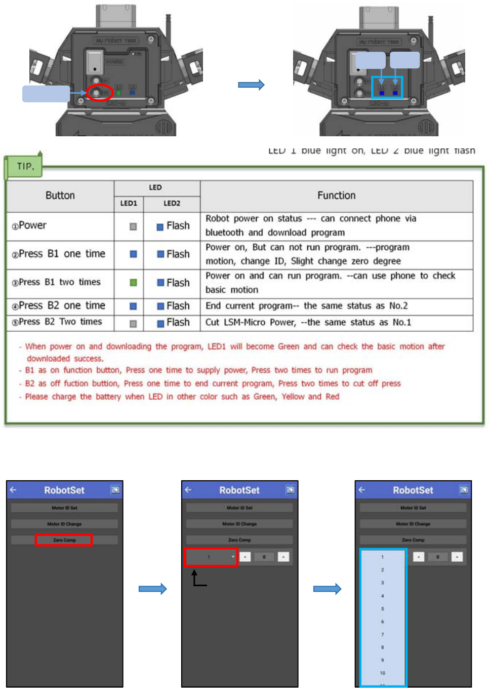
8. Press B2 button one time
9. Press Zero comp button, choose ISM-Micro ID as below picture showed
Button
LED
Function
LED1
LED2
①Power
Flash
Robot power on status --- can connect phone via
bluetooth and download program
②Press B1 one time
Flash
Power on, But can not run program. ---program
motion, change ID, Slight change zero degree
③Press B1 two times
Flash
Power on and can run program. --can use phone to check
basic motion
④Press B2 one time
Flash
End current program-- the same status as No.2
⑤Press B2 Two times
Flash
Cut LSM-Micro Power, --the same status as No.1
LED 1 blue light on, LED 2 blue light flash
B2 Button
LED1
LED2
LSM-micro ID 输入部
66
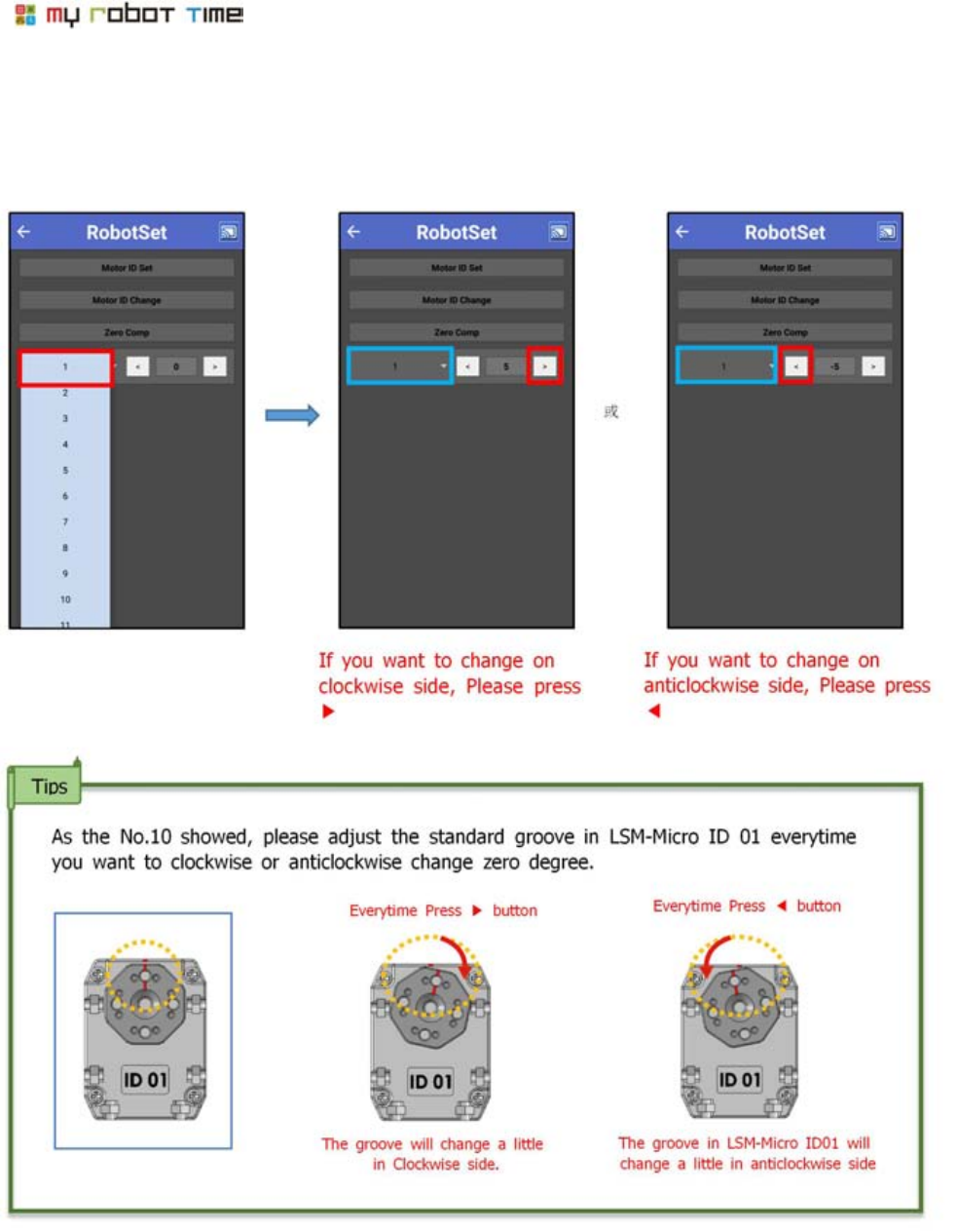
10. Please choose the LSM-Micro ID which need adjust zero degree. Press ◀and ▶button to
adjust zero degree. The range for adjust zero degree is -12 to 12 degree.
11. As the above picture showed, Press ◀and ▶button can adjust zero degree in LSM-Micro, and
save the degree after changed every time.
LINE-Core M
67
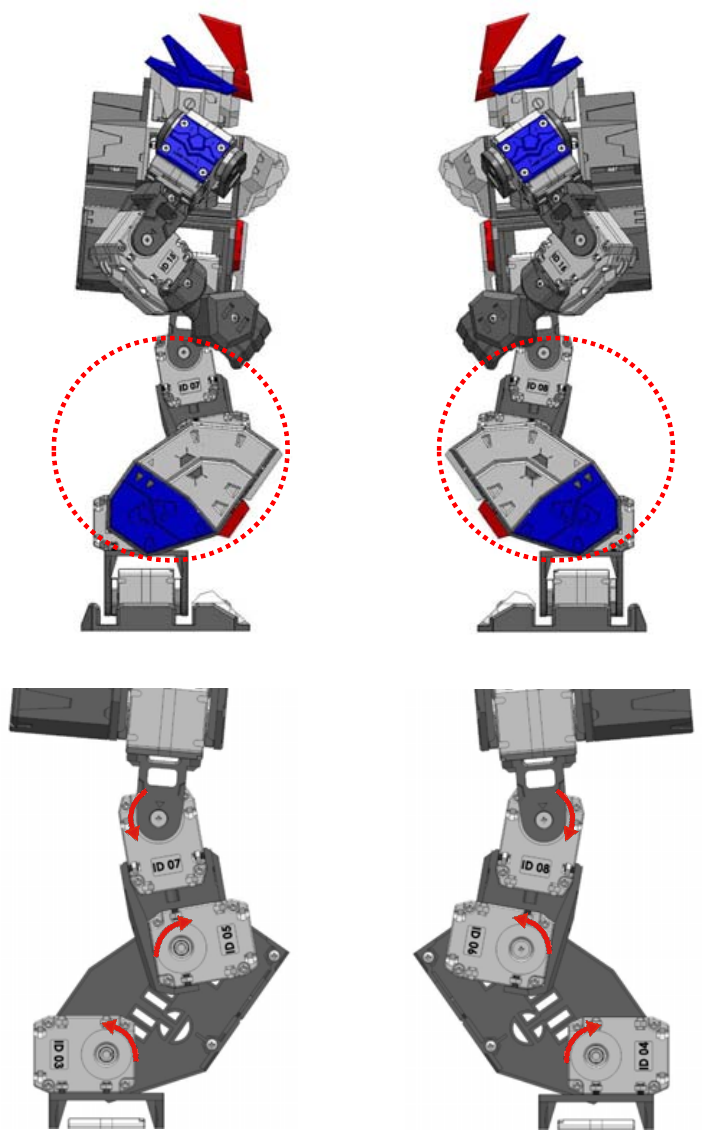
10-3. change the gravity center after equipped with suit.
If equipped with suit, the center of gravity will change, in this case, we need change the center of
gravity in the robot.
Please check below steps to change the gravity center back
ID03 Anticlockwise side
ID05 Clockwise side
ID 07 Anticlockwise side
ID04 Clockwise side
ID06 Anticlockwise side
ID08 Clockwise side
Right leg
Left leg
68
1.~9. Please refer to No1-No9 steps, it is the same way to slight change.
10. Please check below steps to change right leg zero degree( LSM-Micro ID03, ID05, ID07)
11. Please check below steps to change Left leg zero degree( LSM-Micro ID04, ID06, ID08)
Please press ◀to anticlockwise rotate
ID03 motor
Please press ▶to clockwise rotate ID
05 motor
Please press ◀to anticlockwise rotate
ID07 motor
Please press ▶to clockwise rotate ID
04
Please press ◀to anticlockwise rotate
ID06 motor
Please press ▶to anticlockwise rotate
ID08 motor
LINE-Core M
69
12. As the above picture showed, Press ◀and ▶button can adjust zero degree in LSM-Micro, and
save the degree after changed everytime
11. How to run Line Maker App
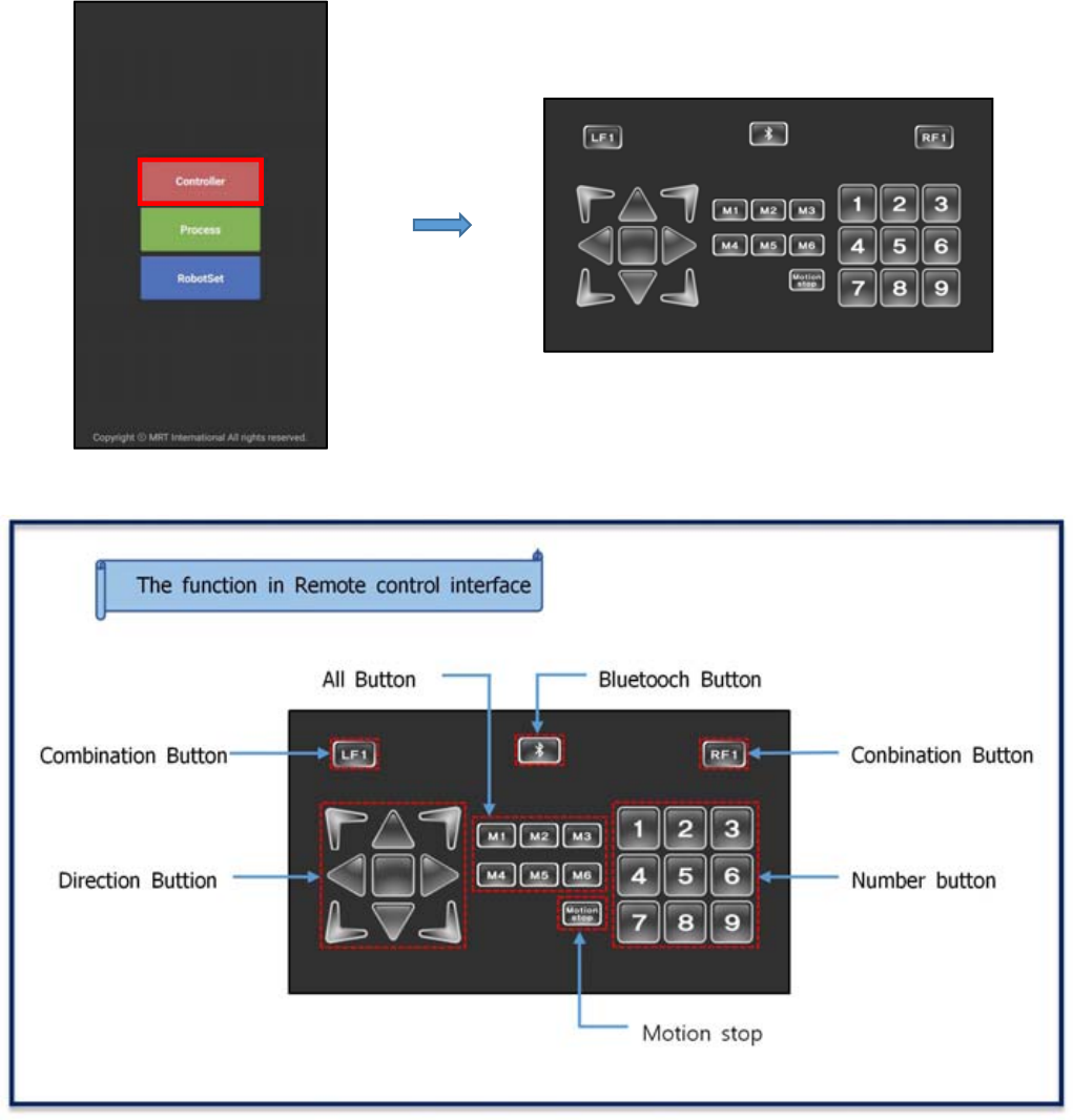
11-1. CONTROLLER
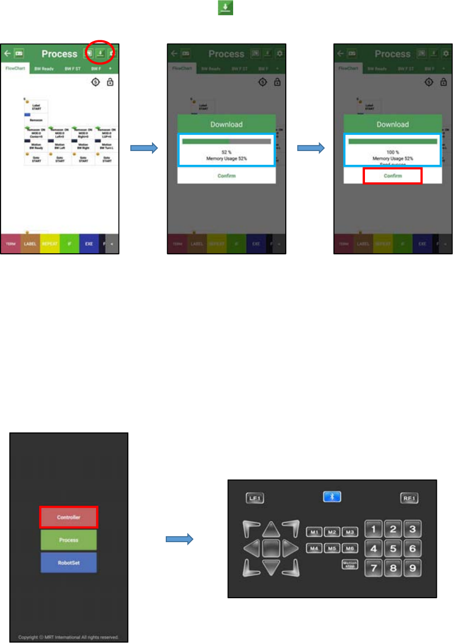
We can use the smart phone as a remote controller to control the robot.
1. Run Line Maker App, choose Controller, enter control interface.
70
2. Please press B1 two times after power on.
3. After press bluetooth button, pease press bluetooth.
4.
4. Please choose yes after bluetooch interface appear in your phone, please choose scan if your
phone showed bluetooth connection.
LSM-Micro power on, LED1 Green
light on, LED2 Blue light flash
LED1
LED2
Power switch
B1 button
※The LED setting different, the program will different, please refer to page 65 tip.
LINE-Core M
71
5. Please choose robot ID, the bluetooch will change color if connected success.
11-1-1. How to control robot
LINE-Core M include basic motion, Boxing, Soccer,Dance, Mission and many other modes, please
check below steps to confirm every mode.
72
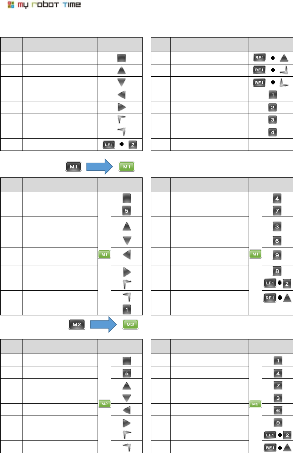
Basic Motion
Front Boxing Mode
Flank Boxing Mode
Serial
No
Motion
Button
Serial
No
Motion
Button
1
Basic Ready motion(bend knee
and stand)
9
Stand up when fall
down(frontside)
2
Move forward
10
Front flip
3
Move Backward
11
Back flip
4
Move left side
12
Bend and Salute
5
Move right Side
13
Wave and Salute
6
Turn Left
14
Victor
7
Turn right
15
Fail
8
Stand up when fall
down(backside)
Serial
No
Motion
Button
Serial
No
Motion
Button
1
Ready
10
left wrist shot
2
Defense
11
Left Uppercut
3
Move Forward
12
Right Straight Punch
4
Move Backward
13
Right wrist shot
5
Move left
14
Right Uppercut
6
Move Right
15
Two hand Straight punch( right
hand first, then left hand)
7
Turn Left
16
stand up when fall down(Back
side)
8
Turn Right
17
Stand up when fall down(Front
9
Left hand stab
Serial
No
Motion
Button
Serial
No
Motion
Button
1
Ready( parting legs, head and
waist turn left)
9
Shoulder attack(left shoulder)
2
Defense
10
Wrist attack(left wrist)
3
Move Forward
11
Stab(left shoulder)
4
Move Backward
12
Rotate attack
5
Move left
13
Right hand stab
6
Move Right
14
Right hand stab, left hand
straight attack
7
Turn Left
15
Stand up when fall down(back
side)
8
Turn right
16
Stand up when fall down(from
side)
press
press
LINE-Core M
73
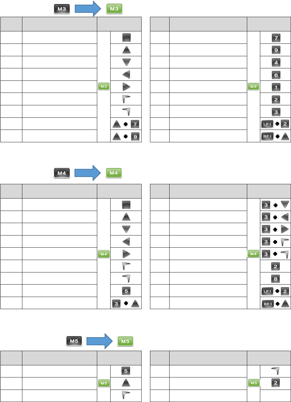
Soccer Mode
Mission Mode
Mission Two mode
Serial
No
Motion
Button
Serial
No
Motion
Button
1
Ready
10
left foot Shoot slightly
2
Move forward(fast)
11
right foot shoot slightly
3
Move Backward(fast)
12
left foot shoot heavily
4
Move left(fast)
13
right foor shoot heavily
5
Move right(fast)
14
goalie cover the shot(left hand)
6
Turn left(fast)
15
Goalie cover the shot(parting
legs and sit down)
7
Turn right(fast)
16
Goalie cover the shot(right
hand)
8
Move forward and turn
left(fast)
17
Stand up when fall down(back
side)
9
Mover forward and turn
right(fast)
18
Stand up when fall down(front
side)
Serial
No
Motion
Button
Serial
No
Motion
Button
1
Ready
10
Hold the object move backward
2
Move forward in quick short
steps
11
Hold the object move left
3
Move backward in quick short
steps
12
Hold the object move right
4
Move Left in quick short steps
13
Hold the object turn left
5
Move Right in quick short
steps
14
Hold the object turn right
6
Turn left in quick short steps
15
Put down the object in stand
status.
7
Turn right in quick short steps
16
Put down the object in sit down
status
8
Sit down and use two hands
grab 5CM object and stand up
17
Stand up when fall down(back
side)
9
Hold the object move forward.
18
Stand up when fall down(front
side)
Serial
No
Motion
Button
Serial
No
Motion
Button
1
Go prone in front side
4
Go prone and turn right
2
Go Prone and move forward
5
Go prone and stand up
3
Go prone and turn left
press
press
press
74
11-1-2. Download Process file
Provide LINE-CORE M Basic motion, Boxing, Soccer, Dance, Mission and other mode program file.
User can download from here if deleted basic motion or other files by mistake,
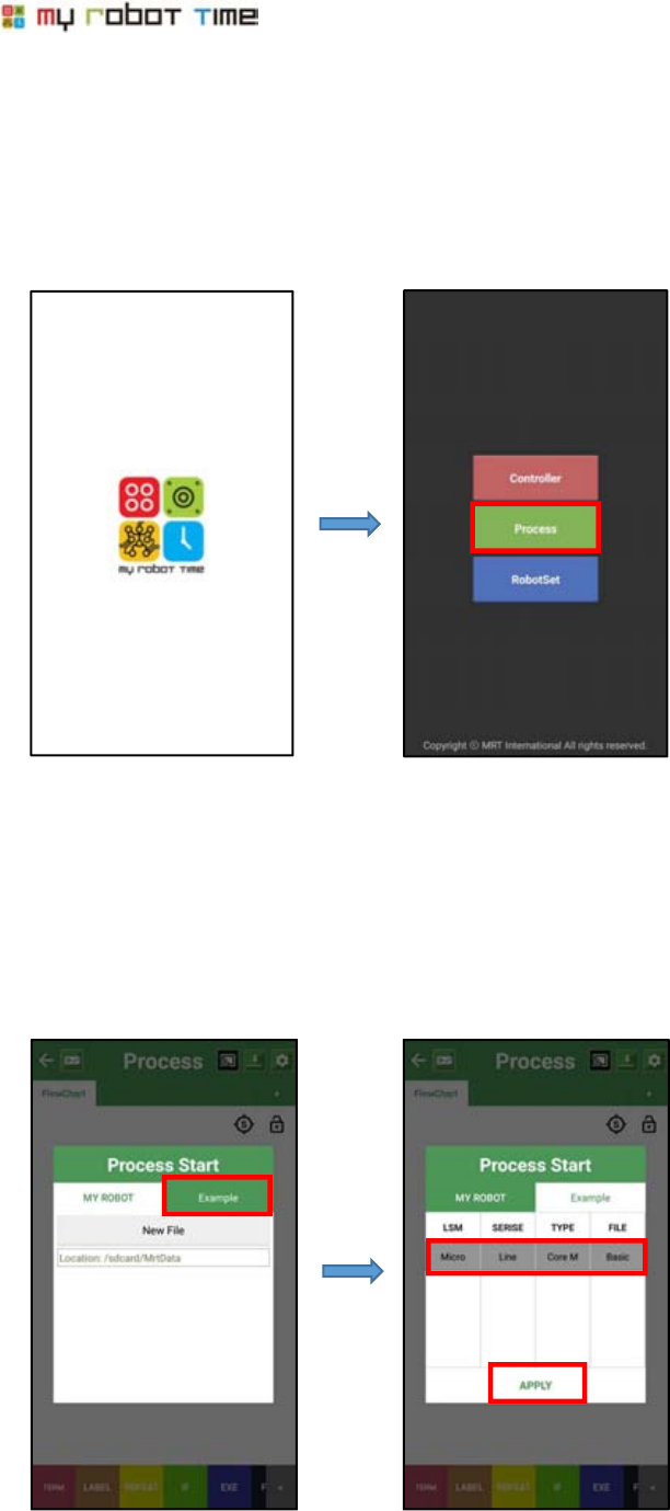
1. Run Line Maker App, and choose process
2. Open Process Start window, choose Example, and choose the program you need and press Apply
button
LINE-Core M
75
3. Please turn on LINE-Core M first.
4. Please press button in Process window, and then press Bluetooth
※Different LED light will run different program, please refer page 65.
电源开关
LED 2 blue light flash with Buzzer sensor
LED1
LED2
76
5. Please choose yes if the bluetooth interface open in your phone
6. Please press Scan, and choose robot ID, the bluetooth will change color after connected success.
※if bluetooth open in your phone, Please refer to No.6
LINE-Core M
77
7. Download the file you need. Please press button to confirm download, after completed,
please press confirm.
8. The LED 1 will become green after download success, user can confirm basic motion from
controller now.
if download failed, Please restart
from 1.
78
12. Change LSM-Micro ID
Line-Core M made by 18 LSM-Micro(ID01-ID18). We need change LSM-Micro id in case the ID repeat
if you want to buy new motor or change motor in the future
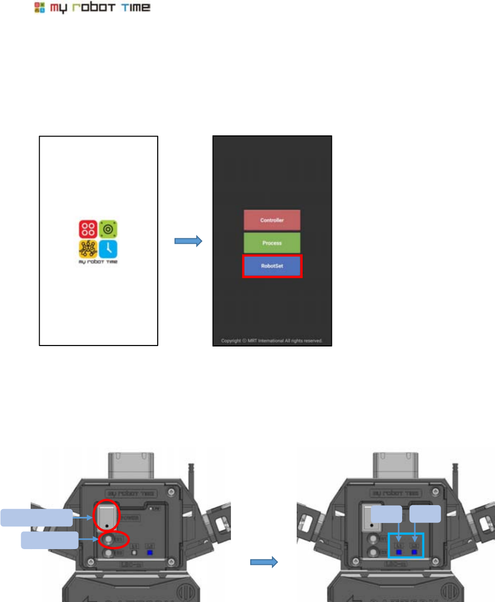
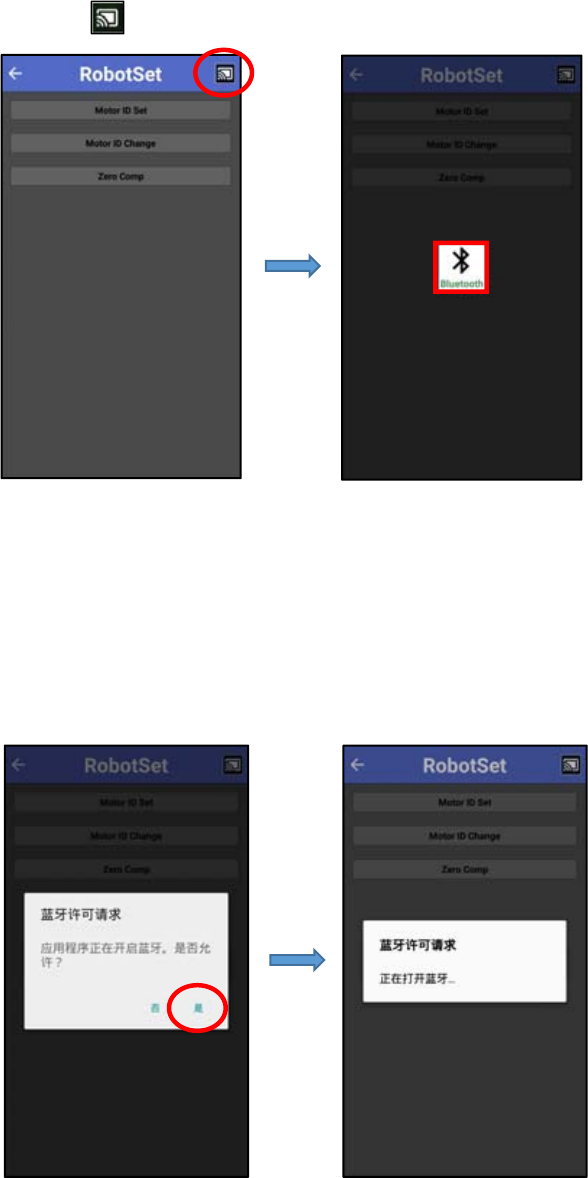
1. Run LINE Maker App, choose RobotSet
2. Turn on the power and press B1 button
B1 button
LED1
LED2
※Different LED will run different program, please refer to page 65
LSM-Micro power on, LED1
Blue light on, LED2 blue light
flash
Power switch
LINE-Core M
79
3. press button in Robotset window and then press bluetooth button
4. Please choose yes if your phone remind you open bluetooth
※ If bluetooth already open in your phone, please refer to No5.
80
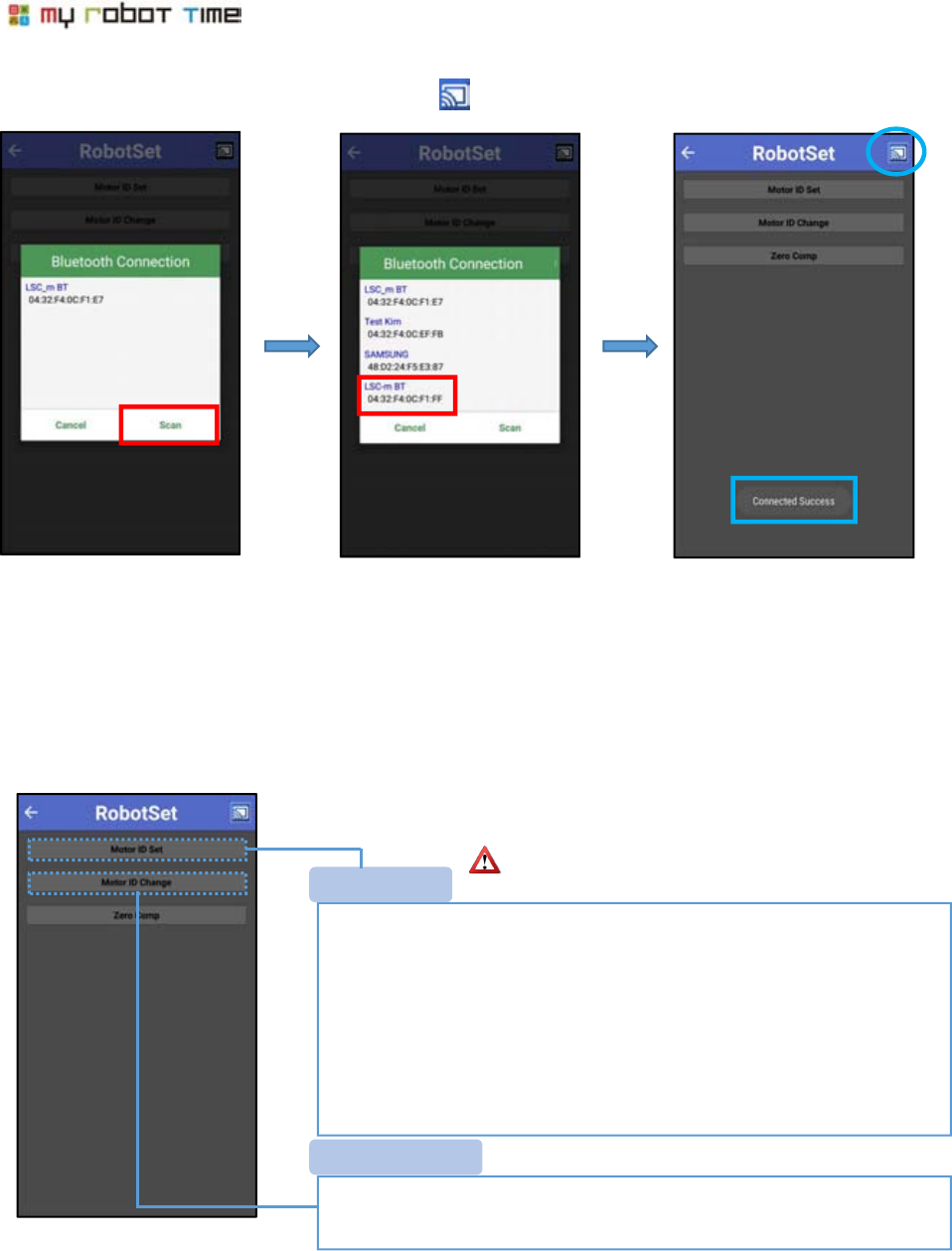
5. Please press Scan, and choose robot ID, the button will change color after connected success
6. There is two ways for change the ID of LSM-Micro
-Change all LSM-Micro which connected with LSC-M into the same ID.
-If only need change one motor ID, Please connect the motor which need
change ID with LSC-M, Then change ID
-If you want to change the ID of the motor that you do not know the ID, Just
need connect this motor with LSC-M and change ID.
-The id of LSM-Micro which buy as spare parts is No.00, if you want to change the ID of spare LSM-Micro, please use Motor
ID Set, it will only need connect one LSM-Micro that need change ID to LSC-M
-The range for ID change is 1-253.
-If Connect one or many LSM-Micro to LSC-M, it can only change one
LSM-Micro ID.
Motor ID S
Motor ID Chang
If the robot finished assembly, please do not use Motor
ID set change ID.
LINE-Core M
81
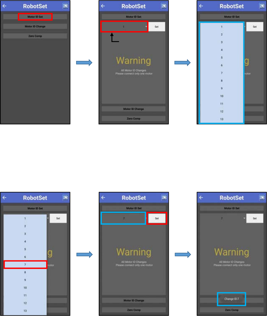
7. Press Motor ID Set Button. As below picture showed, after you pressed ID input button, it
will show the number of ID.
8. Choose the ID that need change, then press Set button.
-After changed ID, It will show the changed ID information.
-If change ID failed, please restart from No.1
-All the LSM-Micro which connected with LSC-M in Motor ID Set will become to the same ID, so please do not use Motor ID
set under the situation that robot finished set.
-If only need change one ID of LSC-Micro, we just connect the LSC-Micro which need change ID to LSC-M.
LSM-micro ID 输入部
82
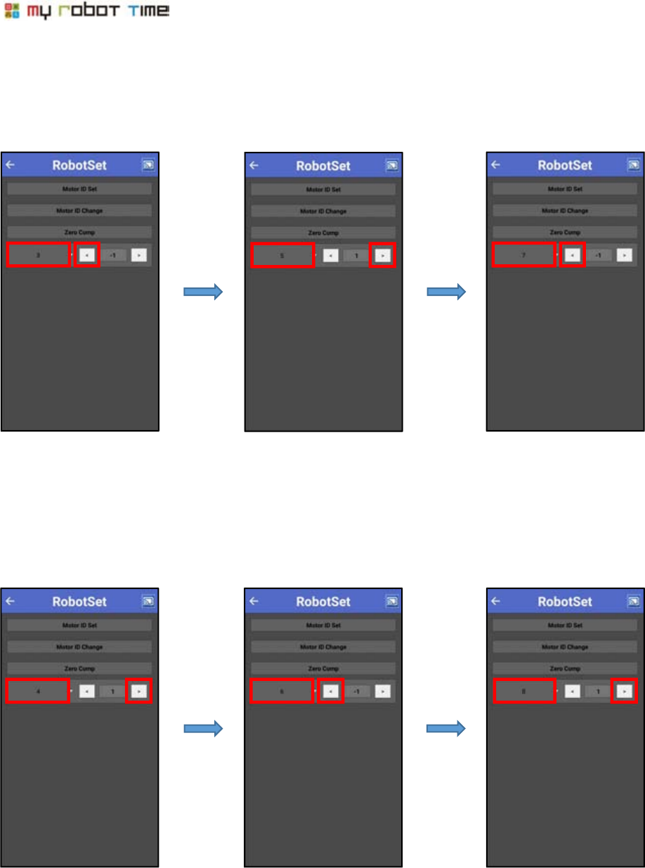
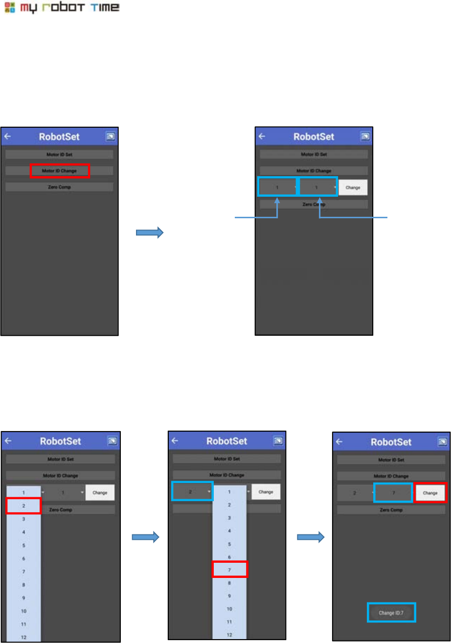
9. How to change the ID of LSM-Micro by using Motor ID Change
Press Motor ID Change button, it will enter the interface as below showed
10. When you want to change ID 02 to ID 07, please press change as below picture showed.
-After changed the ID, it will show the changed ID information
-If change ID failed, please restart from No.1.
-It can only change in LSM-Micrto ID by using Motor ID change, no matter how many LSM-Micro connected to LSC-m
Before ID
change
After ID
change
LINE-Core M
83
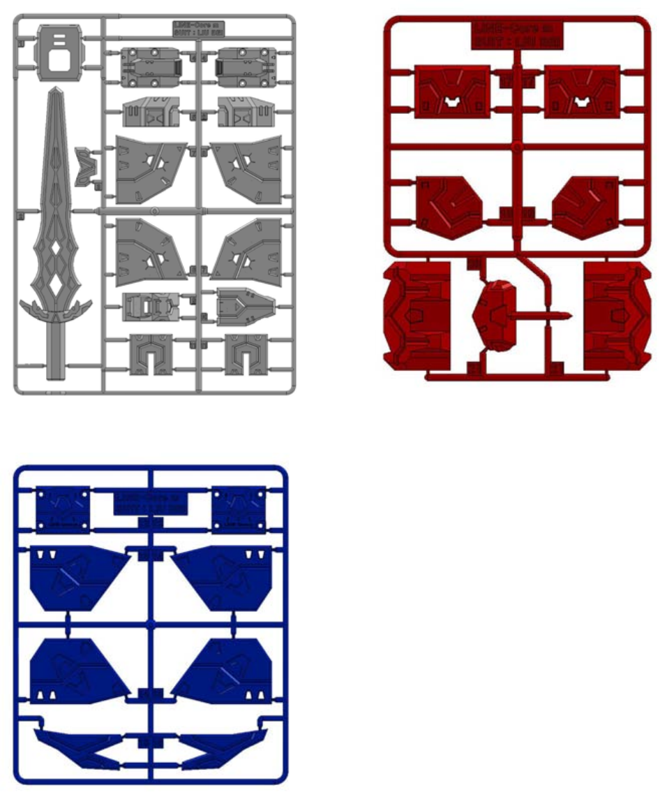
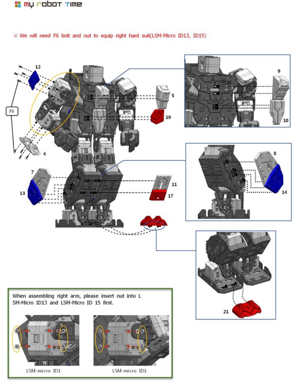
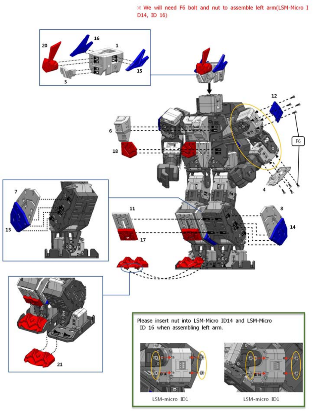
13. How to assembly LINE-Core M suit?
LINE-Core M can do a performance after equipped with different suit. The way for equip the suit is
insert the suit into LINE-Core M frame. It is more faster and convenient to change robot role.
1
2
3
4
4
5
6
7
8
7
8
10
9
11
11
17
17
18
19
20
21
21
12
12
13
14
14
13
15
16
84
LINE-Core M
85
86
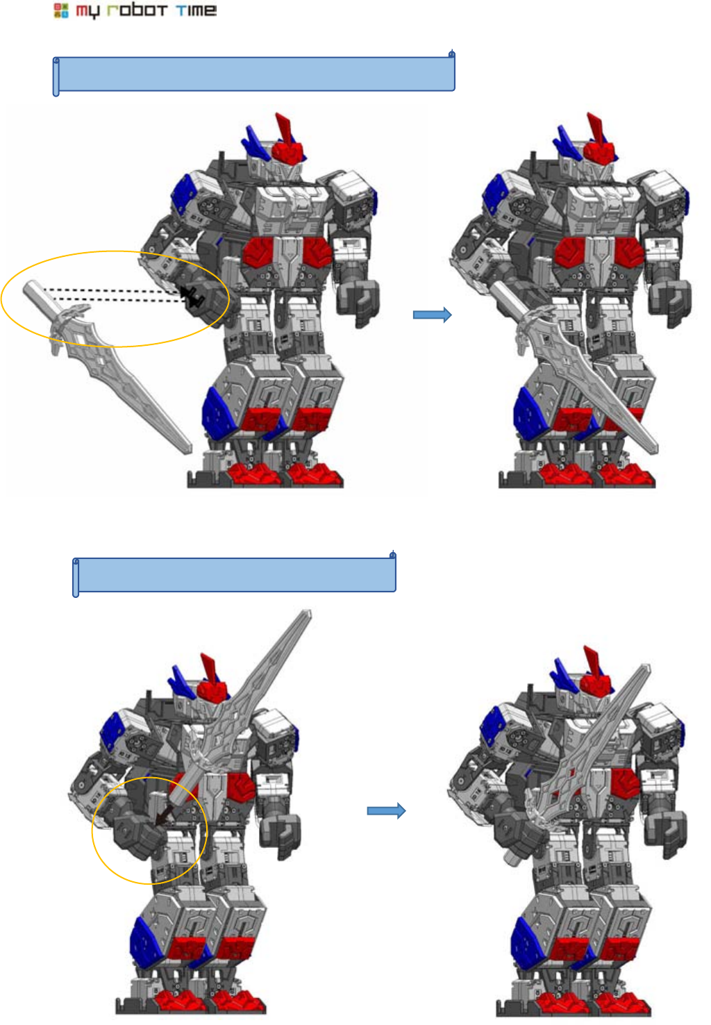
Insert Sword 1--Insert the sword into the back of hand.
Insert Sword 2-- Insert the sword into hand
2
2
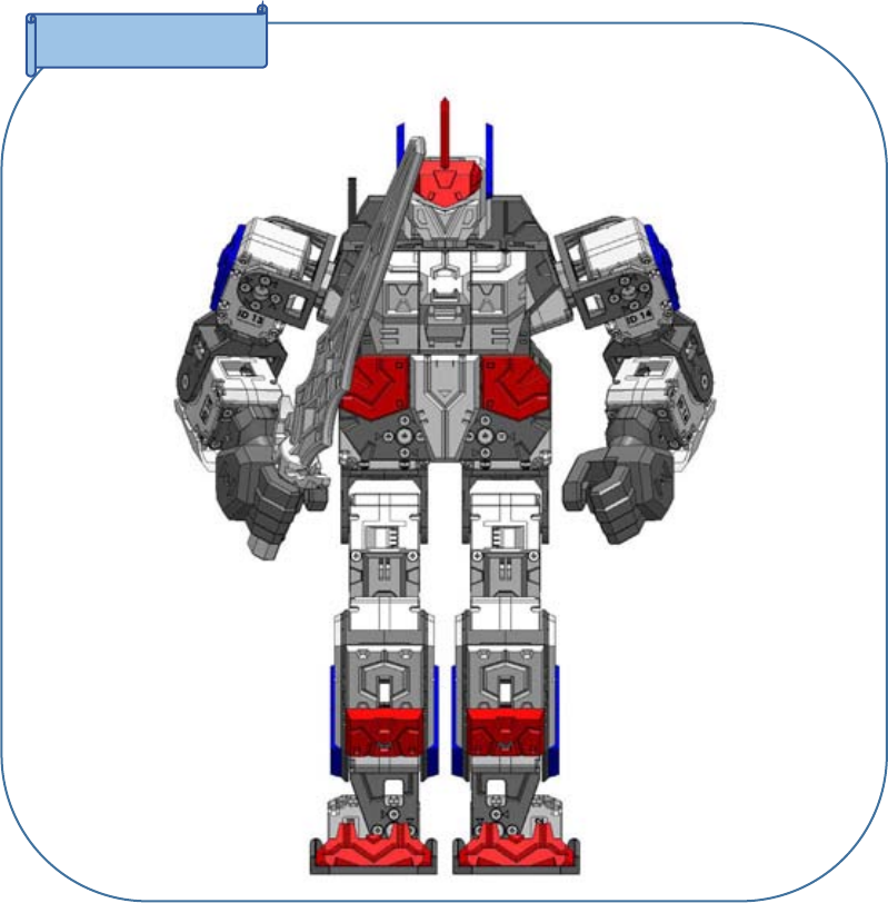
LINE-Core M
87
Completed!
Notes
-After equipped with suit, the gravity center of LSM-Core M will change, we need use slight change to find the right
gravity center.(please refer to page 62-68)
-There is some bluge part in the helmet, please be careful when do some motions such as front flip or back
flip.

88
LINE-Core M
First Edition │2016.06.20
Publisher │MRT International Limited
Company name │Hitechpia Technology(shenzhen) Co.,Ltd
Address │Room210, No1. Maker Zone, China&Canada&Korea International Maker
Park, No.78, Dabao Road,Zone 28, Baoan District, Shenzhen China
Tel │0755-8635-0915
Layout&Execution │MRT ROBOTICS
※The copyright owned by MRT International Limited, can not be printed or for
PDF use.
FCC Information to User
This equipment has been tested and found to comply with the limits for a Class B digital device,
pursuant to Part 15 of the FCC Rules. These limits are designed to provide reasonable protection
against harmful interference in a residential installation. This equipment generates, uses and can
radiate radio frequency energy and, if not installed and used in accordance with the instructions, may
cause harmful interference to radio communications. However, there is no guarantee that interference
will not occur in a particular installation. If this equipment does cause harmful interference to radio or
television reception, which can be determined by turning the equipment off and on, the user is
encouraged to try to correct the interference by one of the following measures:
• Reorient or relocate the receiving antenna.
• Increase the separation between the equipment and receiver.
• Connect the equipment into an outlet on a circuit different from that to which the receiver is con-
nected.
• Consult the dealer or an experienced radio/TV technician for help.
Caution
Modifications not expressly approved by the party responsible for compliance could void the user’s
authority to operate the equipment.
FCC Compliance Information : This device complies with Part 15 of the FCC Rules. Operation is
subject to the following two conditions: (1) This device may not cause harmful interference, and (2)
this device must accept any interference received, including interference that may cause undesired
operation
IMPORTANT NOTE:
FCC RF Radiation Exposure Statement:
This equipment complies with FCC radiation exposure limits set forth for an uncontrolled environment.
This equipment should be installed and operated with minimum distance 0.5cm between the radiator
& your body.
This transmitter must not be co-located or operating in conjunction with any other antenna or
transmitter.