MSA Innovation 10113130 M7 Air Mask User Manual 496958
Mine Safety Appliances Company M7 Air Mask 496958
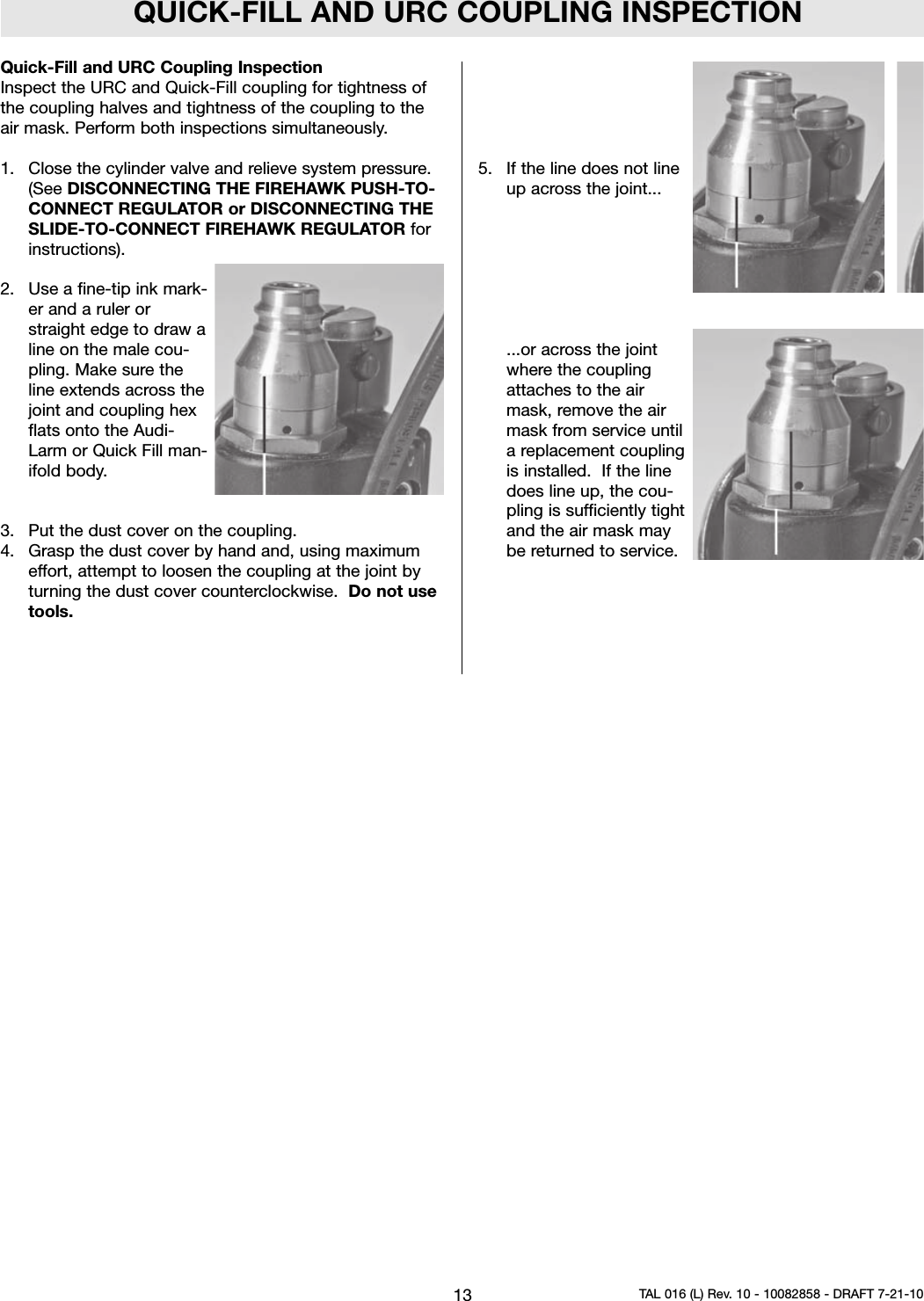
UserManual.wiki
>
MSA Innovation
>
10113130 User Manual
User Manual
Navigation menu
Upload a User Manual
Namespaces
Wiki Guide
HTML
PDF
Info
Views
User Manual
Discussion / Help
Navigation
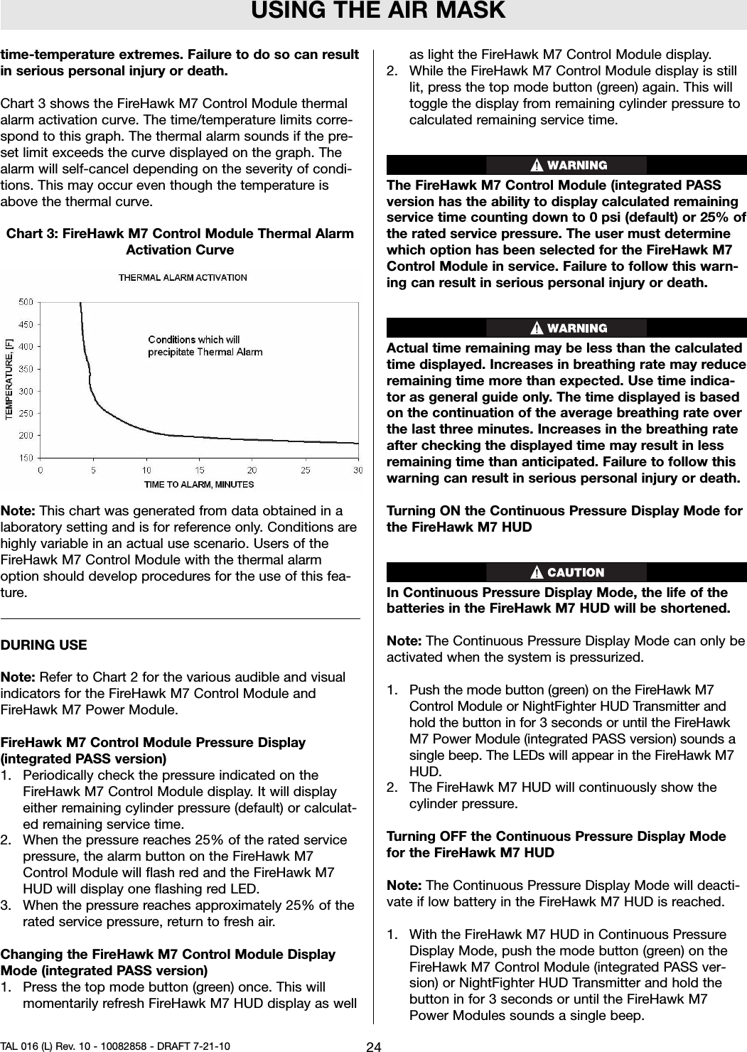
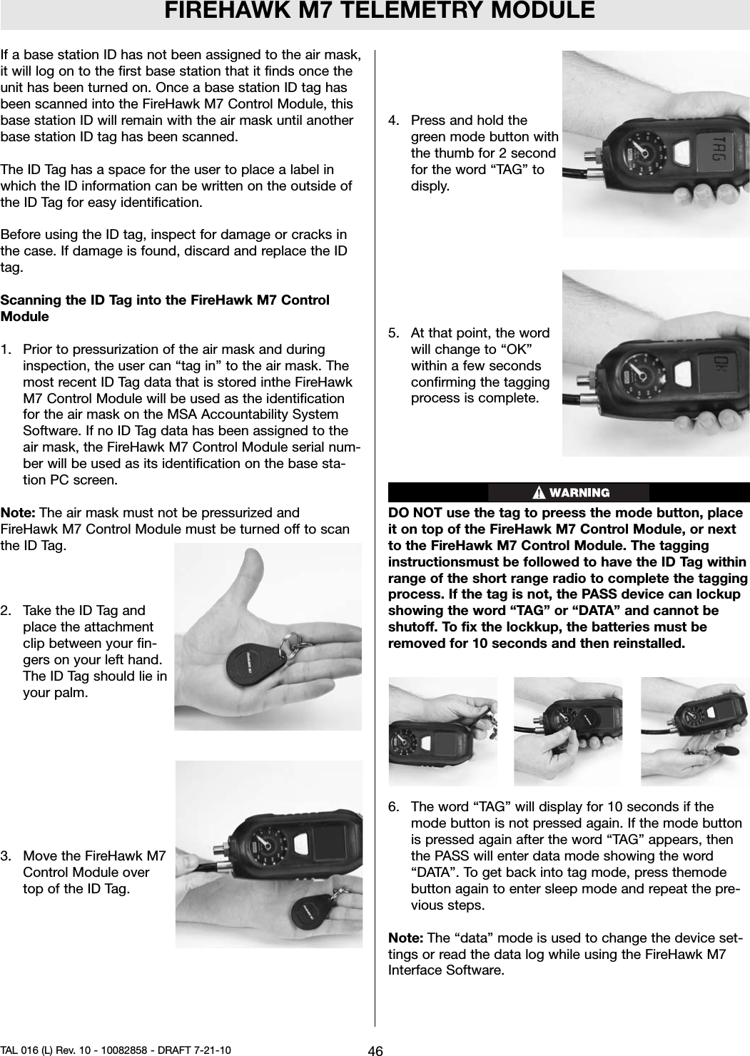
![INTRODUCTIONDo not mark the air mask, i.e., with stamps, labels, paint,or other method. Use of such markings may interfere withapparatus use or may constitute a flammability hazard.For more information on the air mask use and perfor-mance standards, please consult the following publica-tions:NFPA Standard 1500, Fire Department OccupationalSafety and Health Programs (Chapter 5) and NFPA 1981Standard, on Open-Circuit SCBA’s for Fire Service. Abovepublications are available from the following: National FireProtection Association, Batterymarch Park, Quincy, MA22269.ANSI Standard Z88.5, Practices for Respiratory Protectionfor the Fire Service; and, ANSI Standard Z88.2, Practicesfor Respiratory Protection. American National StandardsInstitute, 1430 Broadway, New York, NY 10018.OSHA Safety and Health Standards (29 CFR 1910) (seespecifically Part 1910. 134), available from theSuperintendent of Documents, U. S. Government PrintingOffice, Washington, DC 20402. Compressed GasAssociation, Inc., 1725 Jefferson Davis Hwy., Suite 1004,Arlington, VA 22202.Note: The FireHawk M7 HUD, FireHawk M7 ControlModule, FireHawk M7 Power Module, and NightFighterHUD Transmitter have been tested and found to complywith the limits for a Class B digital device, pursuant toPart 15 of the FCC Rules. These limits are designed toprovide reasonable protection against harmful interferencein a residential installation. This equipment generates,uses, and can radiate radio frequency and, if not installedin accordance with instructions, may cause harmful inter-ference to radio communications. However, there is noguarantee that interference will not occur in a particularinstallation. If this equipment does cause interference toradio or television reception, which can be determined byturning the equipment off and on, the user is encouragedto try to correct the interference by one or more of the fol-lowing measures:• Reorient or relocate the receiving antenna• Increase the separation between the equipment andthe receiver• Connect the equipment into an outlet on a circuit dif-ferent from that to which the receiver is connected.• Consult the dealer or an experienced radio/TV techni-cian for help.The FireHawk M7 HUD, FireHawk M7 Control Module,NightFighter HUD Transmitter, and FireHawk M7Power Module contain electrical parts which have notbeen evaluated as an ignition source in flammable orexplosive atmospheres by MSHA/NIOSH.1. Read and follow all NIOSH and other approval limi-tations.2. DO NOT use the carrier and harness assembly as avertical raising or lowering device.3. DO NOT use the air mask as an underwater device.4. This system must be supplied with respirable[Quality Verification Level (Grade) D, see ANSI/CGAG-7.1-1989] or higher quality air; and a dew pointnot to exceed -65°F (24ppm v/v) [Compressed GasAssociation Specification G-7.1 for QualityVerification Level (Grade) D Gaseous Air]. In fireservice applications, MSA recommends breathingair quality in accordance with NFPA 1989.5. This device may not seal properly with your face ifyou have a beard, gross sideburns or similar physi-cal characteristics (see NFPA-1500 and ANSIZ88.2). An improper facial seal may allow contami-nants to leak into the facepiece, reducing or elimi-nating respiratory protection. Do not use thisdevice if such conditions exist. The face-to-face-piece seal must be tested before each use. Neverremove the facepiece except in a safe, non-haz-ardous, non-toxic atmosphere.6. Return to a safe atmosphere immediately if discol-oration, crazing, blistering, cracking, or other dete-rioration of the facepiece lens material isobserved.7. Users must wear suitable protective clothing andprecautions must be taken so that the air mask isnot exposed to atmospheres that may be harmfulto it.8. Take into account the following factors which mayaffect the duration or the service life.a. the degree of physical activity of the user;b. the physical condition of the user;c. the degree that the user’s breathing rate isincreased by excitement, fear, or other emotionalfactors;d. the degree of training or experience which theuser has had with this or similar equipment;e. whether or not the cylinder is fully charged;f. the presence in the compressed air of carbondioxide concentrations greater than the .04%level normally found in atmospheric air;g. the atmospheric pressure; if used in a pressur-ized tunnel or caisson at 2 atmospheres (15 psigauge) the duration will be one-half as long aswhen used at 1 atmosphere; at 3 atmospheresthe duration will be one-third as long; the servicelife of the air mask is based on 1 atmosphere ofpressure.h. the condition of the air mask.Failure to follow this warning can result in serious per-sonal injury or death.3TAL 016 (L) Rev. 10 - 10082858 - DRAFT 7-21-10](https://usermanual.wiki/MSA-Innovation/10113130/User-Guide-1328023-Page-3.png)
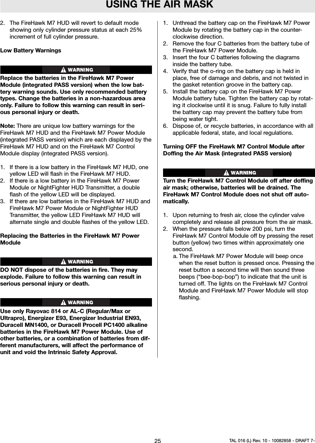
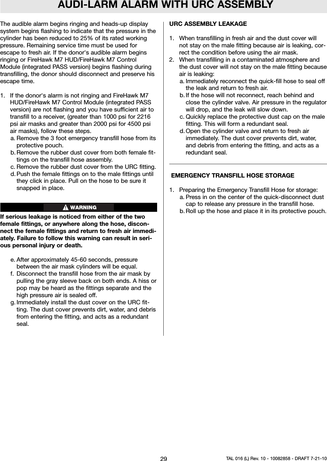
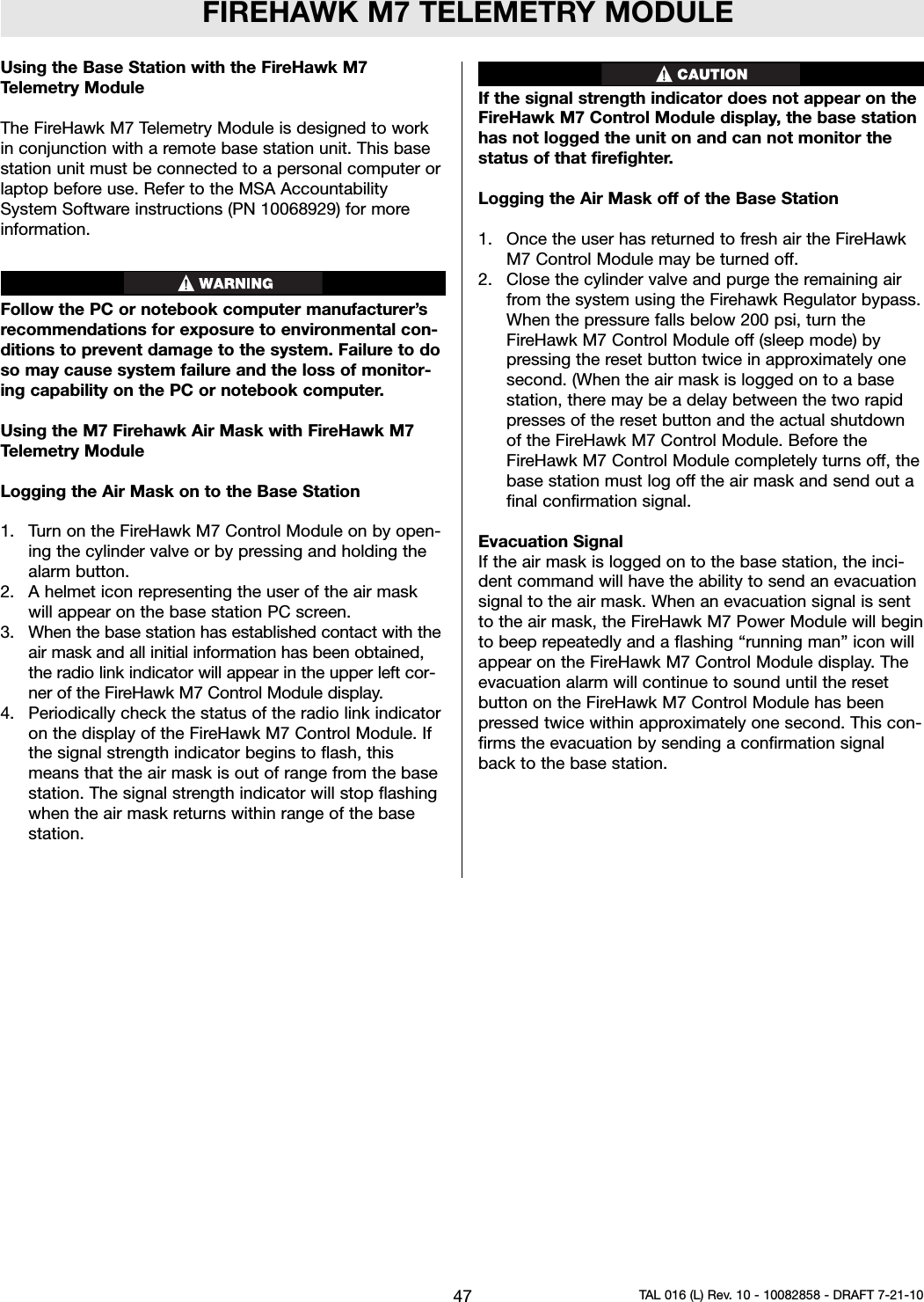
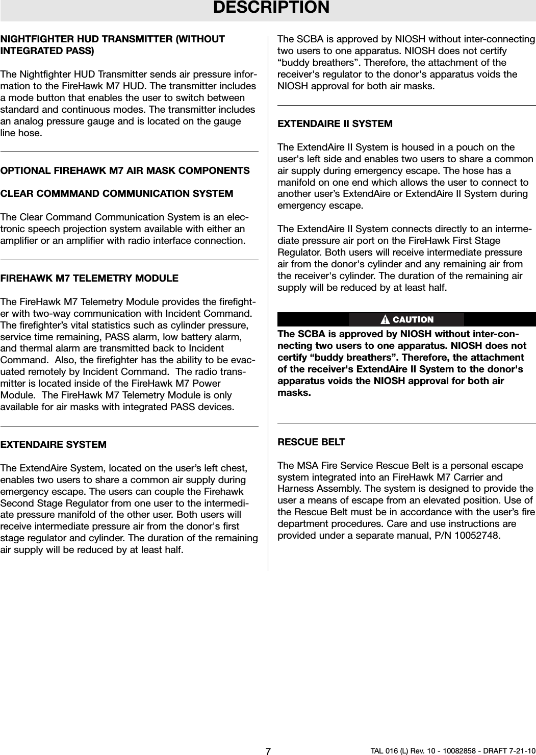
![INTRODUCTIONCBRN AGENT APPROVAL LABELThe MSA CBRN Agent approved air mask has thisapproval label attached to the carrier and harness.IMPORTANT NOTICE FOR RESPIRATOR USERS ANDRESPIRATORY PROTECTION PROGRAMADMINISTRATORS1. An adequate respiratory protection program mustinclude knowledge of hazards, hazard assessment,selection of proper respiratory protective equipment,instruction and training in the use of equipment,inspection and maintenance of equipment, and med-ical surveillance. [See OSHA regulations, Title 29 CFR,Part 1910.134 (c).]2. This SCBA may be used only after proper instructionand training in its use as specified in NFPA-1500 andOSHA regulations Title 29 CFR, Part 1910.134.3. Quantitative fit testing should be conducted to deter-mine proper facepiece size prior to using the respira-tor. A Fit Test Kit (MSA P/N 10044576) is available forconducting quantitative fit tests with the Ultra EliteFirehawk Facepieces. The facepiece donning instruc-tions must be carefully followed when using the respi-rator and when conducting fit tests.5. The CBRN Firehawk Second Stage Regulator must beflow tested every year and overhauled on a periodicbasis. An overhaul kit (MSA P/N 10048942) is avail-able.CONTACT INFORMATIONIn the event of a product concern, contact your local MSAauthorized repair center or distributor, who will provide thenecessary information to MSA for issue resolution. Toreport any serious concerns, or to speak with a certifica-tion organization, ,use the following contact information:ManufacturerMSA Customer ServicePhone: 1-800-MSA-2222Certifying AgenciesNational Institue of Occupational Safety and Health(NIOSH)Phone: 412-386-6686Safety Equipment Institute (SEI)Phone: 703-442-57324TAL 016 (L) Rev. 10 - 10082858 - DRAFT 7-21-10CBRN Agent ApprovedSee Instructions for Required ComponentPart Numbers, Accessories, and AdditionallCautions and Limitations of Use.](https://usermanual.wiki/MSA-Innovation/10113130/User-Guide-1328023-Page-4.png)
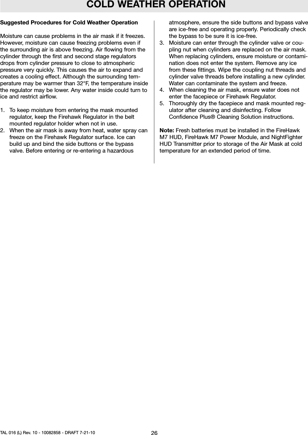
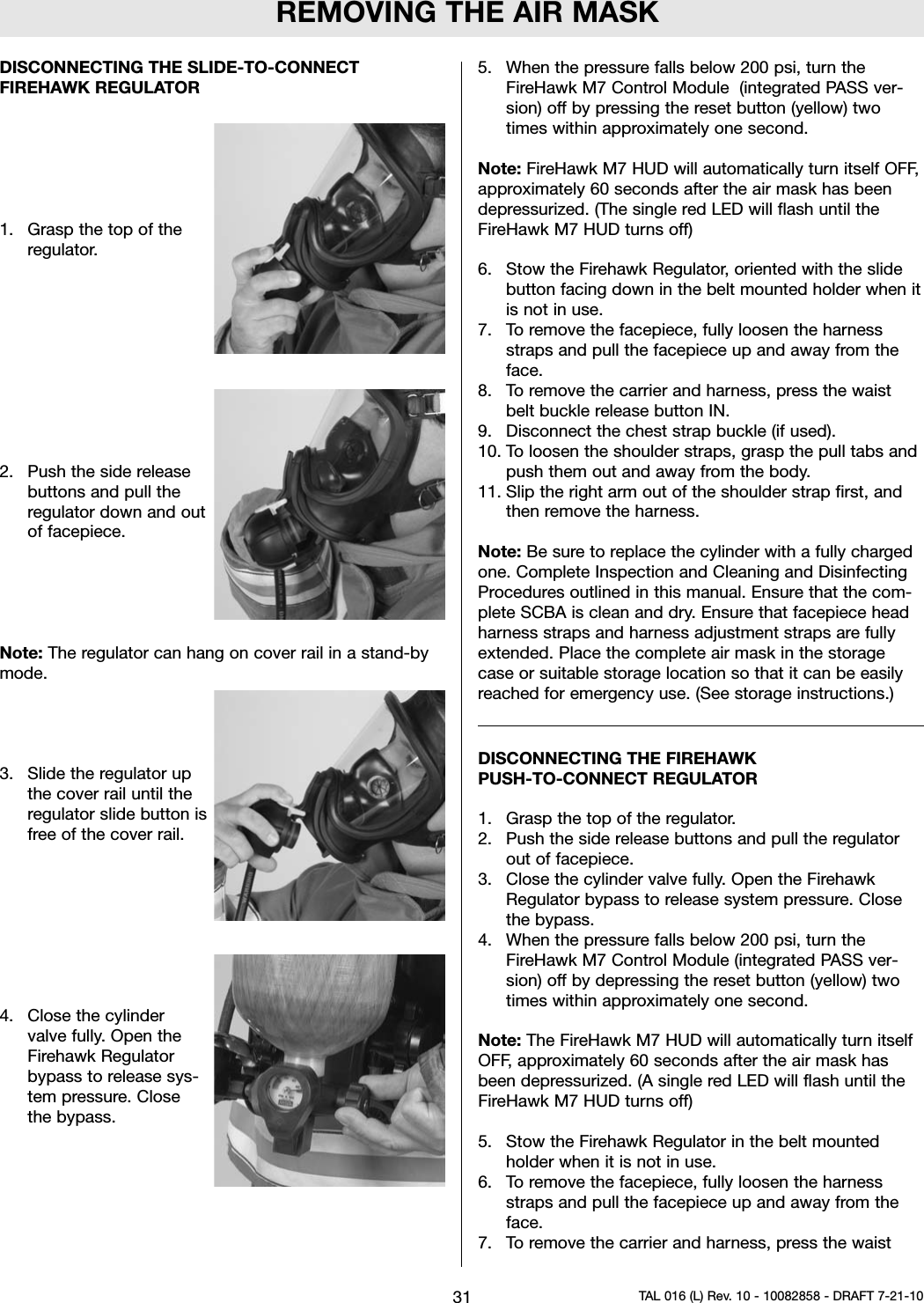
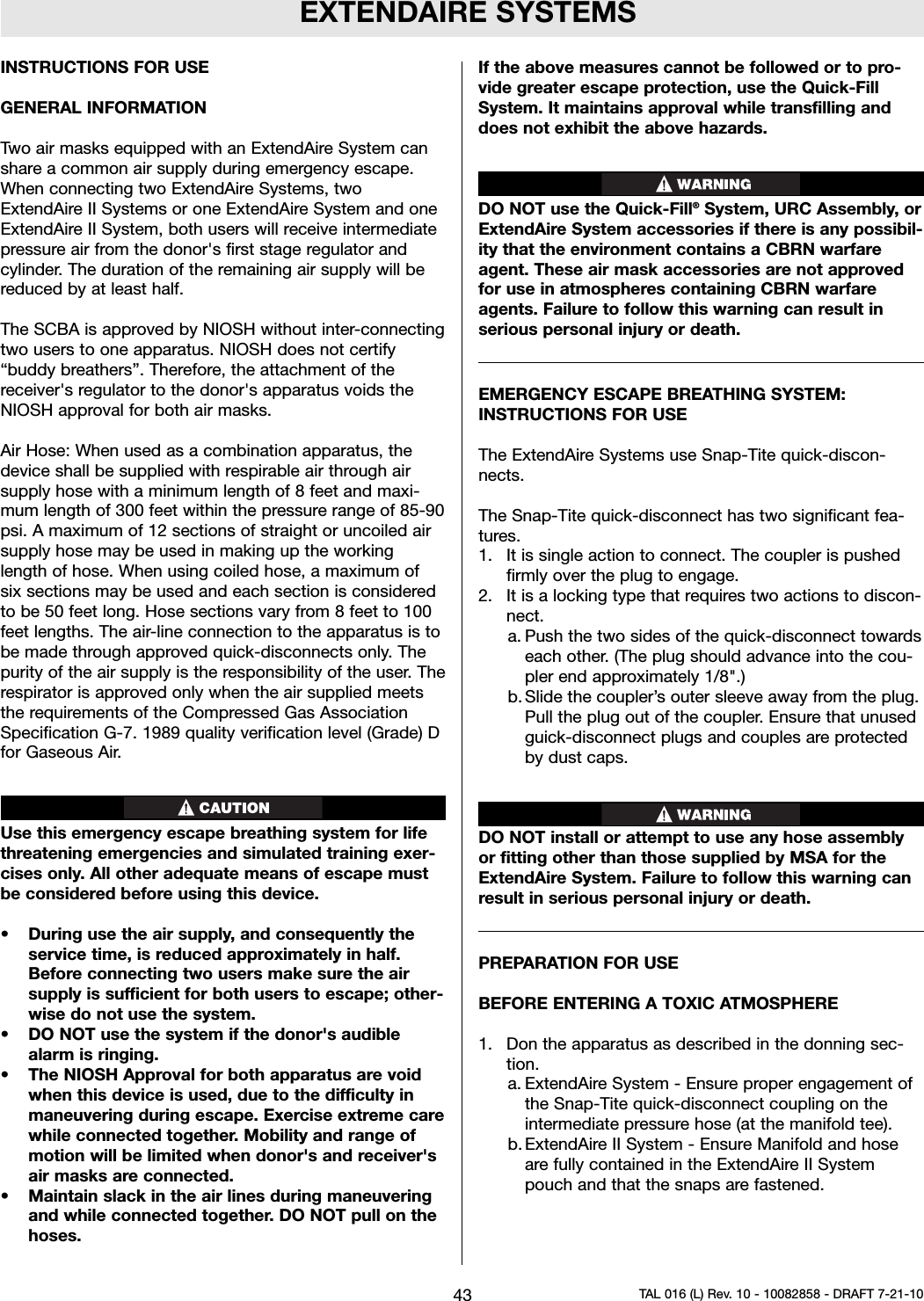
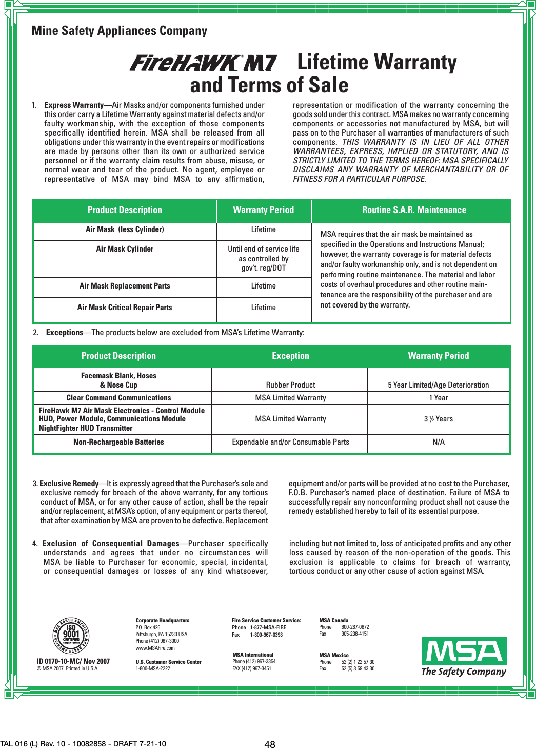
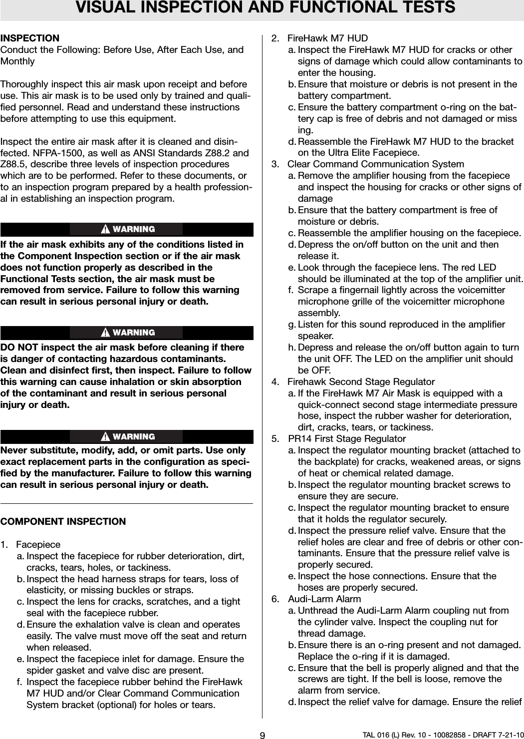
![DESCRIPTIONDESCRIPTIONFireHawk M7 Air Masks from MSA are pressure-demand,self-contained breathing apparatus (SCBA) certified by theNational Institute for Occupational Safety and Health(NIOSH) for use in atmospheres immediately dangerous tolife or health:``Immediately dangerous to life or health’’ means condi-tions that pose an immediate threat to life or health orconditions that pose an immediate threat of severe expo-sure to contaminants, such as radioactive materials,which are likely to have adverse cumulative or delayedeffects on health [Title 42 CFR, Part 84.2, (Q)].This air mask complies with the National Fire ProtectionAssociation (NFPA) Standard 1981 for Open-Circuit Self-Contained Breathing Apparatus for Fire FightersThis air mask has been designated by NIOSH as beingCBRN (chemical, biological, radiological, and nuclear)Agent Approved. It complies with the special tests underNIOSH 42 CFR 84.63(c); Chemical Agent Permeation andPenetration Resistance Against Distilled Sulfur Mustard(HD) and Sarin (GB) and the Laboratory RespiratorProtection Level (LRPL) tests.The FireHawk M7 Air Mask consists of the followingcomponents.• PR14™ First Stage Regulator• Firehawk Second Stage Regulator• Cylinder and Valve Assembly• Audi-Larm™ Audible Alarm with URC Assembly• FireHawk M7 Carrier and Harness Assembly• Ultra Elite®Facepiece• FireHawk M7 HUD• FireHawk M7 Control Module (integrated PASS version)• FireHawk M7 Power Module (integrated PASS version)• NightFighter HUD Transmitter (without integratedPASS version)Optional FIREHAWK M7 AIR MASK COMPONENTS• Clear Command®Communications System• FireHawk M7 Telemetry Module• ExtendAire System• ExtendAire II System• Quick-Fill System• Rescue BeltFIREHAWK M7 AIR MASK COMPONENTSPR14 FIRST STAGE REGULATORThe PR14 First Stage Regulator reduces the pressurefrom the cylinder and valve assembly to an intermediatepressure, which is in turn further reduced by the FirehawkSecond Stage Regulator to a pressure that is respirableby the user.The PR14 First Stage Regulator incorporates a down-stream design and dual springs.The regulator incorporates a large, easily replaceable, sin-tered filter to capture particulates that may be in the airstream.FIREHAWK SECOND STAGE REGULATORThe Firehawk Regulator is a pressure-demand regulator,which maintains a positive pressure in the facepiece whilethe air mask is in use.The Firehawk Regulator attaches to the facepiece via aslide-to-connect or a push-to-connect feature.The Firehawk Regulator has two available covers, purgeand hard cover. The purge cover offers the user the abilityto manually activate the regulator or to provide a quickburst of air during use without using the bypass knob.There are also two types of Firehawk Regulator intermedi-ate pressure hose connections, threaded and quick-con-nect.CYLINDER AND VALVE ASSEMBLY*as approved by NIOSHThe cylinder valve includes a metal valve body, threadedconnection for filling and attachment of the Audi-LarmAlarm, handwheel, safety disc (burst disc), and pressuregauge.The pressure gauge continuously shows the air pressurein the cylinder.The handwheel is used to open and close the cylindervalve.5TAL 016 (L) Rev. 10 - 10082858 - DRAFT 7-21-10Capacity Pressure Rated Svc*Cubic Ft. psig Life (Min.)45 4500 3088 4500 6045 2216 3045 2216 3060 3000 3066 4500 45](https://usermanual.wiki/MSA-Innovation/10113130/User-Guide-1328023-Page-5.png)


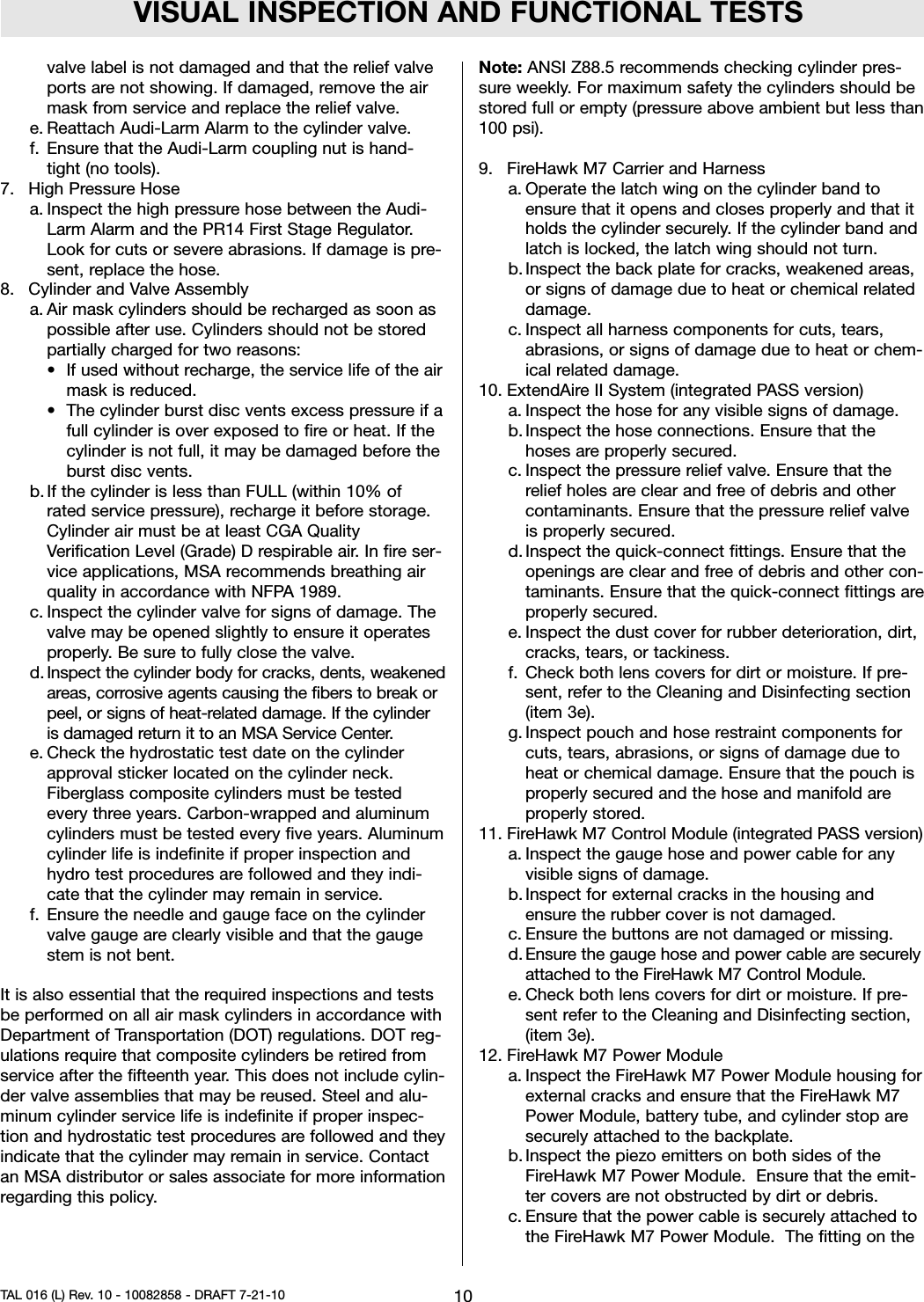

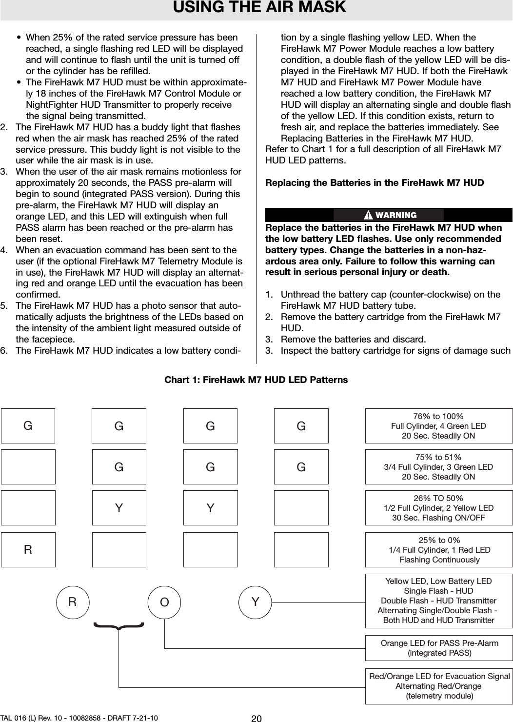
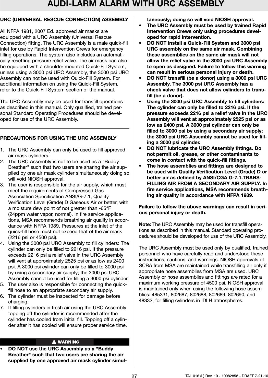
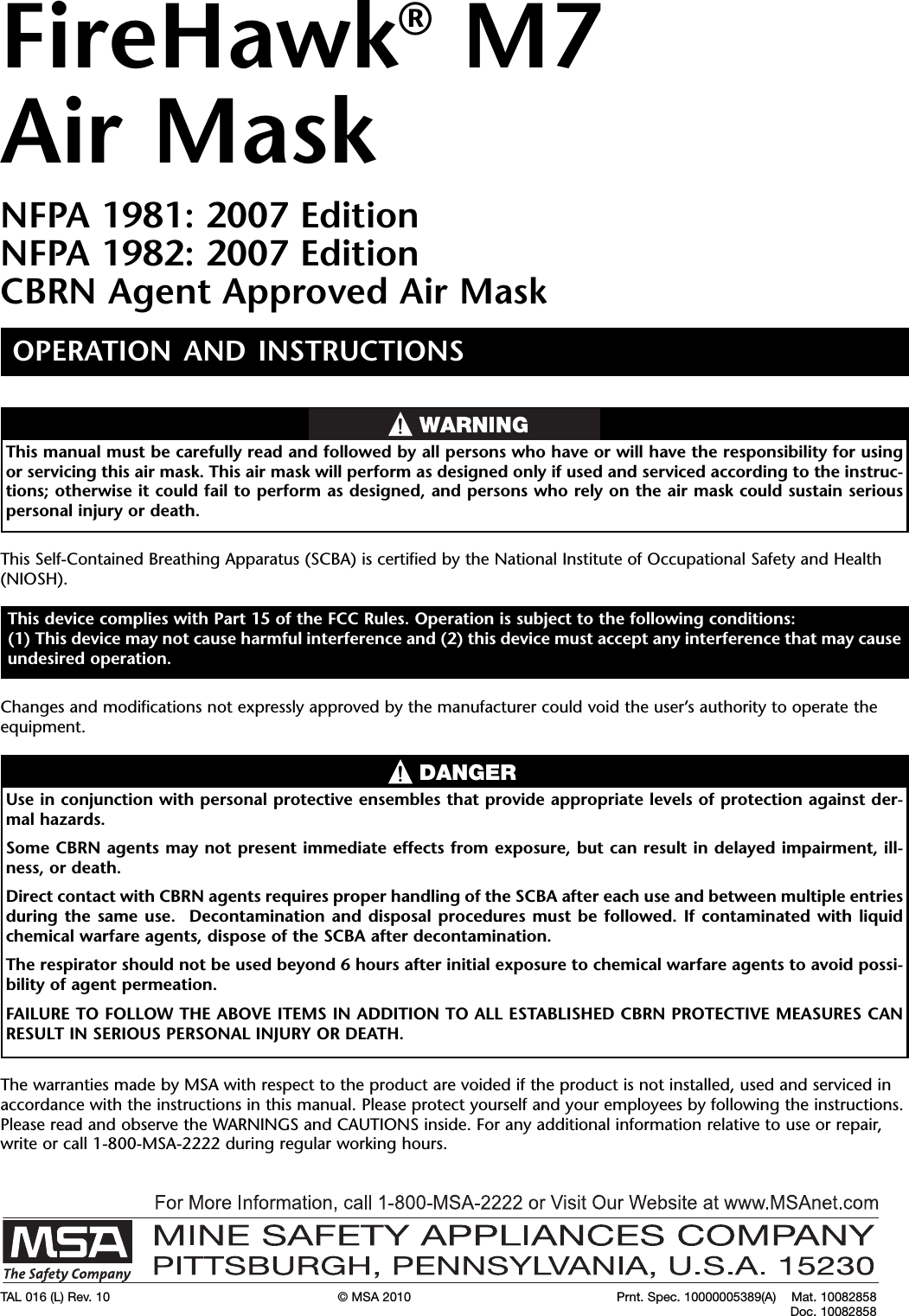
![USING THE AIR MASKPRECAUTIONS DURING USENote: If the breathing apparatus or any component fails,malfunctions, or becomes damaged, contact MSA at 1-800-MSA-2222 [1-800-672-2222] or email customer ser-vice at info@MSAnet.com. SCBA products may be con-sidered hazardous material. In addition, U.S. Departmentof Transportation exceptions and approvals may apply toSCBA products. Please contact customer service at1-800-MSA-2222, or visit www.MSAnet.com/prism, formore information.Periodically check the pressure indicated on the FireHawkM7 chest mounted pressure indicator.• Air flow in the air mask is reduced: Immediately openthe Firehawk Regulator bypass. Immediately return tofresh air.• Air mask free-flows: Immediately return to fresh air.• Audi-Larm Alarm Rings: Immediately return to freshair.• FireHawk M7 HUD low pressure indicator lights andflashes red: Immediately return to fresh air.• FireHawk M7 Control Module (integrated PASS ver-sion) alarm button flashes red: Immediately return tofresh air.Periodically check the pressure indicated on the FireHawkM7 HUD and FireHawk M7 chest mounted pressure indi-cator during use. The FireHawk M7 Control Module con-tinually displays the cylinder pressure while the FireHawkM7 HUD indicates when each quarter of the total cylinderpressure has been reached for 20 seconds. When theneedle on the FireHawk M7 chest mounted pressure indi-cator reaches the red zone on the gauge face the Audi-Larm Alarm will begin ringing, the FireHawk M7 HUD willdisplay a single flashing red LED, and the alarm button onthe FireHawk M7 Control Module (integrated PASS ver-sion) and buddy lights on the FireHawk M7 Power Module(integrated PASS version) will flash red. When the Audi-Larm Alarm starts ringing or when the pressure reachesapproximately 25% of the rated service pressure, returnto fresh air.The FireHawk M7 HUD, FireHawk M7 Control Module(integrated PASS version), and Audi-Larm Alarm indicatewhen cylinder pressure drops below these approximatevalues:530 psi-approximately (2216 psi system)750 psi-approximately (3000 psi system)1125 psi-approximately (4500 psi system)When the FireHawk M7 HUD, FireHawk M7 ControlModule (integrated PASS version), or Audi-Larm Alarmindicates 25% cylinder pressure, immediately return tofresh air.Note: Air mask service life is greatly reduced when theFirehawk Regulator bypass is used.Leave the contaminated area immediately if:• Breathing becomes difficult• Dizziness or other distress occurs• You taste or smell the contaminant• You experience nose or throat irritation• SCBA not functioning according to theinstructions or trainingFailure to follow this warning can result in serious per-sonal injury or death.Note: See NIOSH Approval Label, Inserted in the UsersInstructions for complete list of CAUTIONS and LIMITA-TIONS for the Respirator.Misuse or abuse of the FireHawk M7 HUD, theFireHawk M7 Control Module, FireHawk M7 PowerModule, NightFigher HUD Transmitter or the equip-ment to which they are attached, or using this equip-ment in a manner or situation not intended by themanufacturer, may result in damage to the equipmentor may result in personal injury or death to user orpersons dependent on the user or damage to theequipment.• Always inspect the FireHawk M7 HUD, FireHawkM7 Control Module, NightFighter HUD Transmitterand FireHawk M7 Power Module for damagebefore use. If damage is found, immediatelyremove the device from service.• DO NOT alter these components. Altering will voidthe Intrinsic-Safety rating and may affect theIntrinsic-Safety of the device.FIREHAWK M7 HUDFIREHAWK M7 HUD FUNCTIONALITY1. The FireHawk M7 HUD allows the user to see thecylinder pressure while wearing the air mask. TheFireHawk M7 Control Module or NightFighter HUDTransmitter wirelessly transmits a signal to theFireHawk M7 HUD (on the facepiece) while the airmask is in use. The FireHawk M7 HUD displays thecylinder pressure in one quarter cylinder increments,by an LED pattern.• As each quarter cylinder pressure has beenreached, a unique LED pattern will be displayed forapproximately 20 second before extinguishing. Thedisplay can be refreshed by pressing and holdingthe mode button (green) on the FireHawk M7Control Module or NightFighter HUD Transmitter forapproximately three seconds.19 TAL 016 (L) Rev. 10 - 10082858 - DRAFT 7-21-10](https://usermanual.wiki/MSA-Innovation/10113130/User-Guide-1328023-Page-19.png)