MSA Innovation 10113130 M7 Air Mask User Manual 496958
Mine Safety Appliances Company M7 Air Mask 496958
User Manual
FireHawk®M7
Air Mask
NFPA 1981: 2007 Edition
NFPA 1982: 2007 Edition
CBRN Agent Approved Air Mask
OPERATION AND INSTRUCTIONS
This device complies with Part 15 of the FCC Rules. Operation is subject to the following conditions:
(1) This device may not cause harmful interference and (2) this device must accept any interference that may cause
undesired operation.
TAL 016 (L) Rev. 10 © MSA 2010 Prnt. Spec. 10000005389(A) Mat. 10082858
Doc. 10082858
This manual must be carefully read and followed by all persons who have or will have the responsibility for using
or servicing this air mask. This air mask will perform as designed only if used and serviced according to the instruc-
tions; otherwise it could fail to perform as designed, and persons who rely on the air mask could sustain serious
personal injury or death.
This Self-Contained Breathing Apparatus (SCBA) is certified by the National Institute of Occupational Safety and Health
(NIOSH).
Changes and modifications not expressly approved by the manufacturer could void the user’s authority to operate the
equipment.
Use in conjunction with personal protective ensembles that provide appropriate levels of protection against der-
mal hazards.
Some CBRN agents may not present immediate effects from exposure, but can result in delayed impairment, ill-
ness, or death.
Direct contact with CBRN agents requires proper handling of the SCBA after each use and between multiple entries
during the same use. Decontamination and disposal procedures must be followed. If contaminated with liquid
chemical warfare agents, dispose of the SCBA after decontamination.
The respirator should not be used beyond 6 hours after initial exposure to chemical warfare agents to avoid possi-
bility of agent permeation.
FAILURE TO FOLLOW THE ABOVE ITEMS IN ADDITION TO ALL ESTABLISHED CBRN PROTECTIVE MEASURES CAN
RESULT IN SERIOUS PERSONAL INJURY OR DEATH.
DANGER
The warranties made by MSA with respect to the product are voided if the product is not installed, used and serviced in
accordance with the instructions in this manual. Please protect yourself and your employees by following the instructions.
Please read and observe the WARNINGS and CAUTIONS inside. For any additional information relative to use or repair,
write or call 1-800-MSA-2222 during regular working hours.

INTRODUCTION
NIOSH APPROVAL INFORMATION
CAUTIONS AND LIMITATIONS
I- Contains electrical parts which have not been evaluat-
ed as an ignition source in flammable or explosive
atmospheres by MSHA/NIOSH.
J- Failure to properly use and maintain this product could
result in injury or death.
M- All approved respirators shall be selected, fitted, used
and maintained in accordance with MSHA, OSHA and
other applicable regulations.
N- Never substitute, modify, add or omit parts. Use only
exact replacement parts in the configuration as speci-
fied by the manufacturer.
O- Refer to Users Instructions, and/or maintenance man-
uals for information on use and maintenance of these
respirators.
S- Special or critical User’s Instructions and/or specific
use limitations apply. Refer to user instructions before
donning.
CAUTIONS AND LIMITATIONS OF USE FOR CBRN
SCBA
Q- Use in conjunction with personal protective ensembles
that provide levels of protection against dermal haz-
ards.
R- Some CBRN agents may not present immediate
effects from exposure, but can result in delayed
impairment, illness, or death.
T- Direct contact with CBRN agents requires proper han-
dling of the SCBA after each use and between multi-
ple entries during the same use. Decontamination
and disposal procedures must be followed. If conta-
minated with liquid chemical warfare agents, dispose
of the SCBA after decontamination.
U- The respirator should not be used beyond 6 hours
after initial exposure to chemical warfare agents to
avoid possibility of agent permeation.
S - SPECIAL OR CRITICAL USER’S INSTRUCTIONS
Approved for use at temperatures above -25°F. Approved
only when the compressed-air container is fully charged
with air meeting the requirements of the Compressed Gas
Association Specification G-7 for quality verification level
(grade) D air or equivalent specifications. In fire service
applications, MSA recommends breathing air quality in
accordance with NFPA 1989. The cylinder shall meet
applicable DOT specifications.
Do not alter this air mask. Altering will void the Intrinsic-
Safety rating and may affect the Intrinsic-Safety of the
device. Misuse or abuse of the FireHawk M7 HUD,
FireHawk M7 Control Module, FireHawk M7 Power Module,
or NightFighter HUD Transmitter, or using this equipment in
a manner or situation not intended by the manufacturer,
may result in damage to the FireHawk M7 HUD, FireHawk
M7 Control Module, FireHawk M7 Power Module, or
NightFighter HUD Transmitter, may result in personal injury
or death to user or persons dependent on the user. Always
inspect the FireHawk M7 HUD for damage before use. If
damage is found, immediately remove the device from ser-
vice. The FireHawk M7 HUD, FireHawk M7 Control Module,
FireHawk M7 Power Module, and NightFighter HUD
Transmitter are approved intrinsically-safe and conform to
UL/ANSI 913 for use in Class I, Div. I, Groups C and D haz-
ardous locations, temperature rating T1.
Use the air mask with adequate skin protection when
worn in gases and vapors that poison by skin absorption
(for example: hydrocyanic-acid gas). In making renewals
or repairs, parts identical with those furnished by the
manufacturer under the pertinent approval shall be main-
tained.
Approval for use against CBRN chemical warfare agents
is maintained only when using approved components and
following instructions listed on the NIOSH approval matrix
(P/N 10083874)
2
TAL 016 (L) Rev. 10 - 10082858 - DRAFT 7-21-10
TABLE OF CONTENTS
NIOSHApprovalInformation .........................................................................2
SpecialorCriticalUsersInstructions ...................................................................2
Description .......................................................................................5
InspectionandFunctionalTests .......................................................................9
Quick-FillandURCCouplingInspection ...............................................................13
Donning.........................................................................................15
UsingtheAirMask ................................................................................19
ColdWeatherOperation ............................................................................26
URCAssembly ...................................................................................27
RemovingtheApparatus ...........................................................................31
CleaningandDisinfecting ...........................................................................35
FlowTestandOverhaulRequirements.................................................................37
Quick-Fill®System ................................................................................39
ExtendAire®Systems ..............................................................................43
FireHawkM7TelemetryModule ......................................................................45
WarrantyInformation ..............................................................................48

INTRODUCTION
Do not mark the air mask, i.e., with stamps, labels, paint,
or other method. Use of such markings may interfere with
apparatus use or may constitute a flammability hazard.
For more information on the air mask use and perfor-
mance standards, please consult the following publica-
tions:
NFPA Standard 1500, Fire Department Occupational
Safety and Health Programs (Chapter 5) and NFPA 1981
Standard, on Open-Circuit SCBA’s for Fire Service. Above
publications are available from the following: National Fire
Protection Association, Batterymarch Park, Quincy, MA
22269.
ANSI Standard Z88.5, Practices for Respiratory Protection
for the Fire Service; and, ANSI Standard Z88.2, Practices
for Respiratory Protection. American National Standards
Institute, 1430 Broadway, New York, NY 10018.
OSHA Safety and Health Standards (29 CFR 1910) (see
specifically Part 1910. 134), available from the
Superintendent of Documents, U. S. Government Printing
Office, Washington, DC 20402. Compressed Gas
Association, Inc., 1725 Jefferson Davis Hwy., Suite 1004,
Arlington, VA 22202.
Note: The FireHawk M7 HUD, FireHawk M7 Control
Module, FireHawk M7 Power Module, and NightFighter
HUD Transmitter have been tested and found to comply
with the limits for a Class B digital device, pursuant to
Part 15 of the FCC Rules. These limits are designed to
provide reasonable protection against harmful interference
in a residential installation. This equipment generates,
uses, and can radiate radio frequency and, if not installed
in accordance with instructions, may cause harmful inter-
ference to radio communications. However, there is no
guarantee that interference will not occur in a particular
installation. If this equipment does cause interference to
radio or television reception, which can be determined by
turning the equipment off and on, the user is encouraged
to try to correct the interference by one or more of the fol-
lowing measures:
• Reorient or relocate the receiving antenna
• Increase the separation between the equipment and
the receiver
• Connect the equipment into an outlet on a circuit dif-
ferent from that to which the receiver is connected.
• Consult the dealer or an experienced radio/TV techni-
cian for help.
The FireHawk M7 HUD, FireHawk M7 Control Module,
NightFighter HUD Transmitter, and FireHawk M7
Power Module contain electrical parts which have not
been evaluated as an ignition source in flammable or
explosive atmospheres by MSHA/NIOSH.
1. Read and follow all NIOSH and other approval limi-
tations.
2. DO NOT use the carrier and harness assembly as a
vertical raising or lowering device.
3. DO NOT use the air mask as an underwater device.
4. This system must be supplied with respirable
[Quality Verification Level (Grade) D, see ANSI/CGA
G-7.1-1989] or higher quality air; and a dew point
not to exceed -65°F (24ppm v/v) [Compressed Gas
Association Specification G-7.1 for Quality
Verification Level (Grade) D Gaseous Air]. In fire
service applications, MSA recommends breathing
air quality in accordance with NFPA 1989.
5. This device may not seal properly with your face if
you have a beard, gross sideburns or similar physi-
cal characteristics (see NFPA-1500 and ANSI
Z88.2). An improper facial seal may allow contami-
nants to leak into the facepiece, reducing or elimi-
nating respiratory protection. Do not use this
device if such conditions exist. The face-to-face-
piece seal must be tested before each use. Never
remove the facepiece except in a safe, non-haz-
ardous, non-toxic atmosphere.
6. Return to a safe atmosphere immediately if discol-
oration, crazing, blistering, cracking, or other dete-
rioration of the facepiece lens material is
observed.
7. Users must wear suitable protective clothing and
precautions must be taken so that the air mask is
not exposed to atmospheres that may be harmful
to it.
8. Take into account the following factors which may
affect the duration or the service life.
a. the degree of physical activity of the user;
b. the physical condition of the user;
c. the degree that the user’s breathing rate is
increased by excitement, fear, or other emotional
factors;
d. the degree of training or experience which the
user has had with this or similar equipment;
e. whether or not the cylinder is fully charged;
f. the presence in the compressed air of carbon
dioxide concentrations greater than the .04%
level normally found in atmospheric air;
g. the atmospheric pressure; if used in a pressur-
ized tunnel or caisson at 2 atmospheres (15 psi
gauge) the duration will be one-half as long as
when used at 1 atmosphere; at 3 atmospheres
the duration will be one-third as long; the service
life of the air mask is based on 1 atmosphere of
pressure.
h. the condition of the air mask.
Failure to follow this warning can result in serious per-
sonal injury or death.
3TAL 016 (L) Rev. 10 - 10082858 - DRAFT 7-21-10

INTRODUCTION
CBRN AGENT APPROVAL LABEL
The MSA CBRN Agent approved air mask has this
approval label attached to the carrier and harness.
IMPORTANT NOTICE FOR RESPIRATOR USERS AND
RESPIRATORY PROTECTION PROGRAM
ADMINISTRATORS
1. An adequate respiratory protection program must
include knowledge of hazards, hazard assessment,
selection of proper respiratory protective equipment,
instruction and training in the use of equipment,
inspection and maintenance of equipment, and med-
ical surveillance. [See OSHA regulations, Title 29 CFR,
Part 1910.134 (c).]
2. This SCBA may be used only after proper instruction
and training in its use as specified in NFPA-1500 and
OSHA regulations Title 29 CFR, Part 1910.134.
3. Quantitative fit testing should be conducted to deter-
mine proper facepiece size prior to using the respira-
tor. A Fit Test Kit (MSA P/N 10044576) is available for
conducting quantitative fit tests with the Ultra Elite
Firehawk Facepieces. The facepiece donning instruc-
tions must be carefully followed when using the respi-
rator and when conducting fit tests.
5. The CBRN Firehawk Second Stage Regulator must be
flow tested every year and overhauled on a periodic
basis. An overhaul kit (MSA P/N 10048942) is avail-
able.
CONTACT INFORMATION
In the event of a product concern, contact your local MSA
authorized repair center or distributor, who will provide the
necessary information to MSA for issue resolution. To
report any serious concerns, or to speak with a certifica-
tion organization, ,use the following contact information:
Manufacturer
MSA Customer Service
Phone: 1-800-MSA-2222
Certifying Agencies
National Institue of Occupational Safety and Health
(NIOSH)
Phone: 412-386-6686
Safety Equipment Institute (SEI)
Phone: 703-442-5732
4
TAL 016 (L) Rev. 10 - 10082858 - DRAFT 7-21-10
CBRN Agent Approved
See Instructions for Required Component
Part Numbers, Accessories, and Additionall
Cautions and Limitations of Use.
DESCRIPTION
DESCRIPTION
FireHawk M7 Air Masks from MSA are pressure-demand,
self-contained breathing apparatus (SCBA) certified by the
National Institute for Occupational Safety and Health
(NIOSH) for use in atmospheres immediately dangerous to
life or health:
``Immediately dangerous to life or health’’ means condi-
tions that pose an immediate threat to life or health or
conditions that pose an immediate threat of severe expo-
sure to contaminants, such as radioactive materials,
which are likely to have adverse cumulative or delayed
effects on health [Title 42 CFR, Part 84.2, (Q)].
This air mask complies with the National Fire Protection
Association (NFPA) Standard 1981 for Open-Circuit Self-
Contained Breathing Apparatus for Fire Fighters
This air mask has been designated by NIOSH as being
CBRN (chemical, biological, radiological, and nuclear)
Agent Approved. It complies with the special tests under
NIOSH 42 CFR 84.63(c); Chemical Agent Permeation and
Penetration Resistance Against Distilled Sulfur Mustard
(HD) and Sarin (GB) and the Laboratory Respirator
Protection Level (LRPL) tests.
The FireHawk M7 Air Mask consists of the following
components.
• PR14™ First Stage Regulator
• Firehawk Second Stage Regulator
• Cylinder and Valve Assembly
• Audi-Larm™ Audible Alarm with URC Assembly
• FireHawk M7 Carrier and Harness Assembly
• Ultra Elite®Facepiece
• FireHawk M7 HUD
• FireHawk M7 Control Module (integrated PASS version)
• FireHawk M7 Power Module (integrated PASS version)
• NightFighter HUD Transmitter (without integrated
PASS version)
Optional FIREHAWK M7 AIR MASK COMPONENTS
• Clear Command®Communications System
• FireHawk M7 Telemetry Module
• ExtendAire System
• ExtendAire II System
• Quick-Fill System
• Rescue Belt
FIREHAWK M7 AIR MASK COMPONENTS
PR14 FIRST STAGE REGULATOR
The PR14 First Stage Regulator reduces the pressure
from the cylinder and valve assembly to an intermediate
pressure, which is in turn further reduced by the Firehawk
Second Stage Regulator to a pressure that is respirable
by the user.
The PR14 First Stage Regulator incorporates a down-
stream design and dual springs.
The regulator incorporates a large, easily replaceable, sin-
tered filter to capture particulates that may be in the air
stream.
FIREHAWK SECOND STAGE REGULATOR
The Firehawk Regulator is a pressure-demand regulator,
which maintains a positive pressure in the facepiece while
the air mask is in use.
The Firehawk Regulator attaches to the facepiece via a
slide-to-connect or a push-to-connect feature.
The Firehawk Regulator has two available covers, purge
and hard cover. The purge cover offers the user the ability
to manually activate the regulator or to provide a quick
burst of air during use without using the bypass knob.
There are also two types of Firehawk Regulator intermedi-
ate pressure hose connections, threaded and quick-con-
nect.
CYLINDER AND VALVE ASSEMBLY
*as approved by NIOSH
The cylinder valve includes a metal valve body, threaded
connection for filling and attachment of the Audi-Larm
Alarm, handwheel, safety disc (burst disc), and pressure
gauge.
The pressure gauge continuously shows the air pressure
in the cylinder.
The handwheel is used to open and close the cylinder
valve.
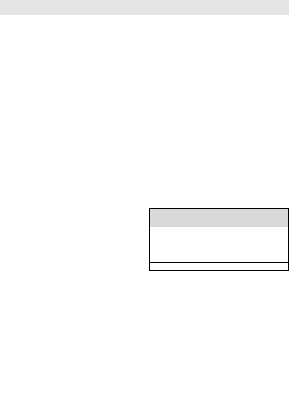
5TAL 016 (L) Rev. 10 - 10082858 - DRAFT 7-21-10
Capacity Pressure Rated Svc*
Cubic Ft. psig Life (Min.)
45 4500 30
88 4500 60
45 2216 30
45 2216 30
60 3000 30
66 4500 45
AUDI-LARM ALARM WITH URC ASSEMBLY
The Audi-Larm Alarm rings when there is approximately
25% of the air mask’s rated service time remaining and
when the cylinder valve is first opened, providing an audi-
ble indication that the alarm is working properly.
A high pressure hose delivers air at cylinder pressure from
the Audi-Larm Alarm to the PR14 First Stage Regulator.
Note: The remaining service time calculations are based
on a 40 LPM (liters per minute) NIOSH breathing rate.
All FireHawk M7 Air Masks are equipped with an Audi-
Larm Alarm that includes a URC Assembly (Universal
Rescue Connection). The URC Assembly is a male quick-
fill inlet for use by Rapid Intervention Crews for emer-
gency filling of the SCBA or during transfill operations.
Also included with the URC Assembly is a pressure relief
valve for protection of the cylinder burst disc.
FIREHAWK M7 CARRIER AND HARNESS ASSEMBLY
DO NOT use this carrier and harness assembly as a
vertical raising or lowering device. Failure to follow
this warning can result in serious personal injury or
death.
The carrier consists of a backplate, a cylinder band with
latch to hold the cylinder, and a harness, consisting of
shoulder pads, chest strap (optional), adjustable pull straps,
waist belt, waist belt mounted regulator retainer, swiveling
lumbar pad (optional), and Rescue Belt (optional).
ULTRA ELITE FACEPIECE
The facepiece is available in three sizes (Small, Medium,
and Large).
The facepiece lens is super-hardcoated to meet the
requirements of NFPA 1981.
The facepiece has a low-resistance, pressure-demand
exhalation valve.
An inhalation check valve in the inlet housing keeps mois-
ture and contaminants out of the Firehawk Regulator.
The facepiece has a speaking diaphragm for clear com-
munication.
FIREHAWK M7 HUD
The FireHawk M7 HUD, located on the Ultra Elite
Facepiece allows a user to see cylinder pressure in one
quarter cylinder increments, PASS pre-alarms (integrated
PASS version), battery status, and telemetry information
(optional) while wearing the air mask.
FIREHAWK M7 CONTROL MODULE (INTEGRATED
PASS VERSION)
The FireHawk M7 Control Module is the user’s interface
with the air mask.
The FireHawk M7 Control Module is equipped with an
analog gauge as well as an LCD to provide the user vital
information: numeric and iconic cylinder pressure, battery
status, thermal alarm (optional), and time remaining.
The FireHawk M7 Control Module is only present on air
masks with integrated PASS devices.
If the air mask is equipped with the optional FireHawk M7
Telemetry Module, the radio link status and evacuation
alarms are displayed.
The integrated PASS motion sensor is housed within the
FireHawk M7 Control Module.
FIREHAWK M7 POWER MODULE (INTEGRATED PASS
VERSION)
The FireHawk M7 Power Module on the lower portion of
the backplate houses the batteries, serves as the cylinder
stop, emits audible PASS alarms, and has buddy lights.
The FireHawk M7 Power Module is linked to the FireHawk
M7 Control Module via the power cable.
The FireHawk M7 Power Module is only present on air
masks with integrated PASS devices.
DESCRIPTION
6
TAL 016 (L) Rev. 10 - 10082858 - DRAFT 7-21-10
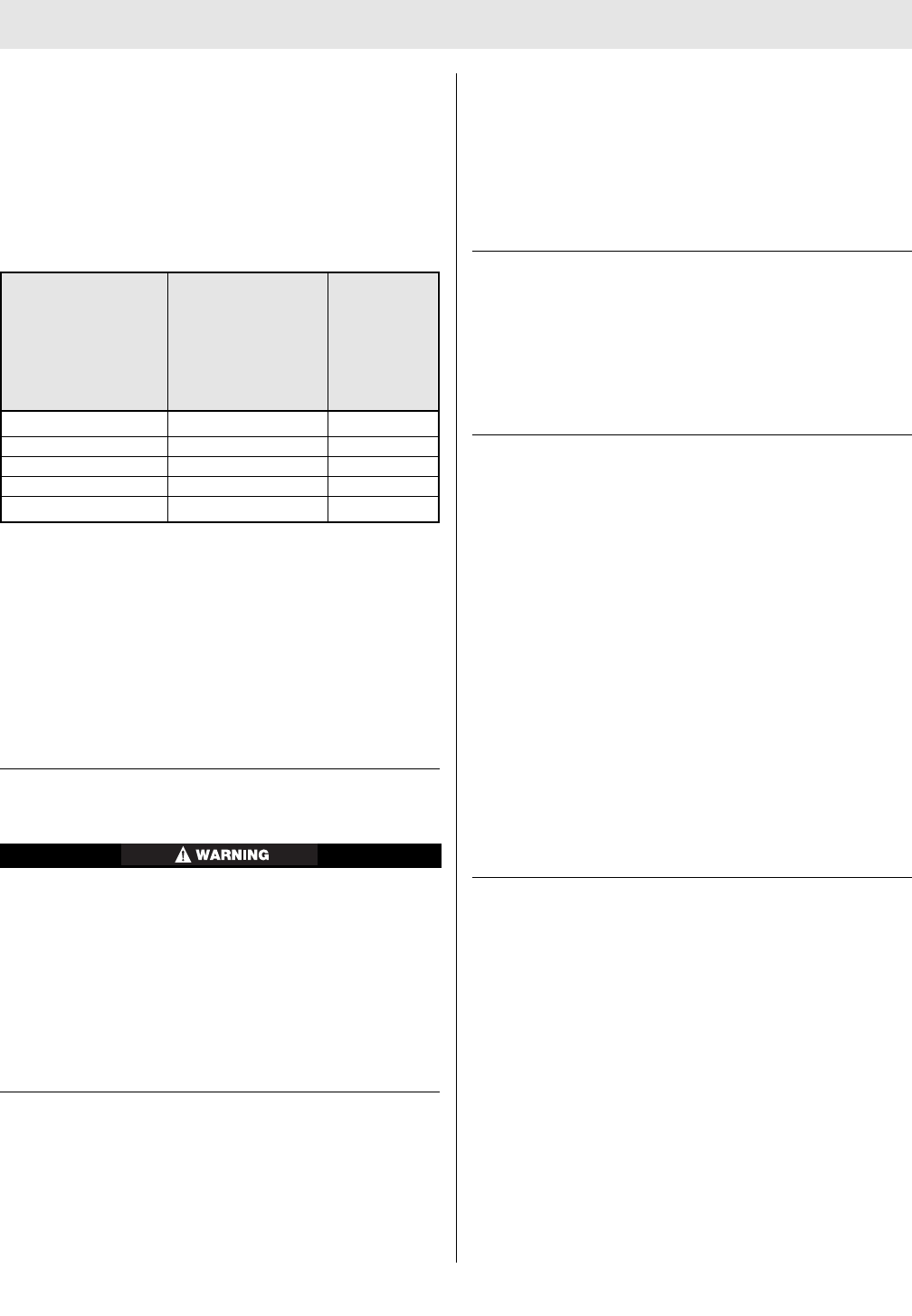
End of
Service
Cylinder Remaining Service Time
Time (Approx.) Indicator
Pressure
(Approx)
30 min. 2216 psi 7 minutes 530 psi
30 min. 3000 psi 10 minutes 750 psi
30 min. 4500 psi 7 minutes 1125 psi
45 min. 4500 psi 11 minutes 1125 psi
60 min. 4500 psi 14 minutes 1125 psi
DESCRIPTION
NIGHTFIGHTER HUD TRANSMITTER (WITHOUT
INTEGRATED PASS)
The Nightfighter HUD Transmitter sends air pressure infor-
mation to the FireHawk M7 HUD. The transmitter includes
a mode button that enables the user to switch between
standard and continuous modes. The transmitter includes
an analog pressure gauge and is located on the gauge
line hose.
OPTIONAL FIREHAWK M7 AIR MASK COMPONENTS
CLEAR COMMMAND COMMUNICATION SYSTEM
The Clear Command Communication System is an elec-
tronic speech projection system available with either an
amplifier or an amplifier with radio interface connection.
FIREHAWK M7 TELEMETRY MODULE
The FireHawk M7 Telemetry Module provides the firefight-
er with two-way communication with Incident Command.
The firefighter’s vital statistics such as cylinder pressure,
service time remaining, PASS alarm, low battery alarm,
and thermal alarm are transmitted back to Incident
Command. Also, the firefighter has the ability to be evac-
uated remotely by Incident Command. The radio trans-
mitter is located inside of the FireHawk M7 Power
Module. The FireHawk M7 Telemetry Module is only
available for air masks with integrated PASS devices.
EXTENDAIRE SYSTEM
The ExtendAire System, located on the user’s left chest,
enables two users to share a common air supply during
emergency escape. The users can couple the Firehawk
Second Stage Regulator from one user to the intermedi-
ate pressure manifold of the other user. Both users will
receive intermediate pressure air from the donor's first
stage regulator and cylinder. The duration of the remaining
air supply will be reduced by at least half.
The SCBA is approved by NIOSH without inter-connecting
two users to one apparatus. NIOSH does not certify
“buddy breathers”. Therefore, the attachment of the
receiver's regulator to the donor's apparatus voids the
NIOSH approval for both air masks.
EXTENDAIRE II SYSTEM
The ExtendAire II System is housed in a pouch on the
user's left side and enables two users to share a common
air supply during emergency escape. The hose has a
manifold on one end which allows the user to connect to
another user’s ExtendAire or ExtendAire II System during
emergency escape.
The ExtendAire II System connects directly to an interme-
diate pressure air port on the FireHawk First Stage
Regulator. Both users will receive intermediate pressure
air from the donor's cylinder and any remaining air from
the receiver's cylinder. The duration of the remaining air
supply will be reduced by at least half.
The SCBA is approved by NIOSH without inter-con-
necting two users to one apparatus. NIOSH does not
certify “buddy breathers”. Therefore, the attachment
of the receiver's ExtendAire II System to the donor's
apparatus voids the NIOSH approval for both air
masks.
RESCUE BELT
The MSA Fire Service Rescue Belt is a personal escape
system integrated into an FireHawk M7 Carrier and
Harness Assembly. The system is designed to provide the
user a means of escape from an elevated position. Use of
the Rescue Belt must be in accordance with the user’s fire
department procedures. Care and use instructions are
provided under a separate manual, P/N 10052748.
7TAL 016 (L) Rev. 10 - 10082858 - DRAFT 7-21-10

NOTES
8
TAL 016 (L) Rev. 10 - 10082858 - DRAFT 7-21-10
VISUAL INSPECTION AND FUNCTIONAL TESTS
INSPECTION
Conduct the Following: Before Use, After Each Use, and
Monthly
Thoroughly inspect this air mask upon receipt and before
use. This air mask is to be used only by trained and quali-
fied personnel. Read and understand these instructions
before attempting to use this equipment.
Inspect the entire air mask after it is cleaned and disin-
fected. NFPA-1500, as well as ANSI Standards Z88.2 and
Z88.5, describe three levels of inspection procedures
which are to be performed. Refer to these documents, or
to an inspection program prepared by a health profession-
al in establishing an inspection program.
If the air mask exhibits any of the conditions listed in
the Component Inspection section or if the air mask
does not function properly as described in the
Functional Tests section, the air mask must be
removed from service. Failure to follow this warning
can result in serious personal injury or death.
DO NOT inspect the air mask before cleaning if there
is danger of contacting hazardous contaminants.
Clean and disinfect first, then inspect. Failure to follow
this warning can cause inhalation or skin absorption
of the contaminant and result in serious personal
injury or death.
Never substitute, modify, add, or omit parts. Use only
exact replacement parts in the configuration as speci-
fied by the manufacturer. Failure to follow this warning
can result in serious personal injury or death.
COMPONENT INSPECTION
1. Facepiece
a. Inspect the facepiece for rubber deterioration, dirt,
cracks, tears, holes, or tackiness.
b. Inspect the head harness straps for tears, loss of
elasticity, or missing buckles or straps.
c. Inspect the lens for cracks, scratches, and a tight
seal with the facepiece rubber.
d. Ensure the exhalation valve is clean and operates
easily. The valve must move off the seat and return
when released.
e. Inspect the facepiece inlet for damage. Ensure the
spider gasket and valve disc are present.
f. Inspect the facepiece rubber behind the FireHawk
M7 HUD and/or Clear Command Communication
System bracket (optional) for holes or tears.
2. FireHawk M7 HUD
a. Inspect the FireHawk M7 HUD for cracks or other
signs of damage which could allow contaminants to
enter the housing.
b. Ensure that moisture or debris is not present in the
battery compartment.
c. Ensure the battery compartment o-ring on the bat-
tery cap is free of debris and not damaged or miss
ing.
d. Reassemble the FireHawk M7 HUD to the bracket
on the Ultra Elite Facepiece.
3. Clear Command Communication System
a. Remove the amplifier housing from the facepiece
and inspect the housing for cracks or other signs of
damage
b. Ensure that the battery compartment is free of
moisture or debris.
c. Reassemble the amplifier housing on the facepiece.
d. Depress the on/off button on the unit and then
release it.
e. Look through the facepiece lens. The red LED
should be illuminated at the top of the amplifier unit.
f. Scrape a fingernail lightly across the voicemitter
microphone grille of the voicemitter microphone
assembly.
g. Listen for this sound reproduced in the amplifier
speaker.
h. Depress and release the on/off button again to turn
the unit OFF. The LED on the amplifier unit should
be OFF.
4. Firehawk Second Stage Regulator
a. If the FireHawk M7 Air Mask is equipped with a
quick-connect second stage intermediate pressure
hose, inspect the rubber washer for deterioration,
dirt, cracks, tears, or tackiness.
5. PR14 First Stage Regulator
a. Inspect the regulator mounting bracket (attached to
the backplate) for cracks, weakened areas, or signs
of heat or chemical related damage.
b. Inspect the regulator mounting bracket screws to
ensure they are secure.
c. Inspect the regulator mounting bracket to ensure
that it holds the regulator securely.
d. Inspect the pressure relief valve. Ensure that the
relief holes are clear and free of debris or other con-
taminants. Ensure that the pressure relief valve is
properly secured.
e. Inspect the hose connections. Ensure that the
hoses are properly secured.
6. Audi-Larm Alarm
a. Unthread the Audi-Larm Alarm coupling nut from
the cylinder valve. Inspect the coupling nut for
thread damage.
b. Ensure there is an o-ring present and not damaged.
Replace the o-ring if it is damaged.
c. Ensure that the bell is properly aligned and that the
screws are tight. If the bell is loose, remove the
alarm from service.
d. Inspect the relief valve for damage. Ensure the relief
9TAL 016 (L) Rev. 10 - 10082858 - DRAFT 7-21-10

VISUAL INSPECTION AND FUNCTIONAL TESTS
valve label is not damaged and that the relief valve
ports are not showing. If damaged, remove the air
mask from service and replace the relief valve.
e. Reattach Audi-Larm Alarm to the cylinder valve.
f. Ensure that the Audi-Larm coupling nut is hand-
tight (no tools).
7. High Pressure Hose
a. Inspect the high pressure hose between the Audi-
Larm Alarm and the PR14 First Stage Regulator.
Look for cuts or severe abrasions. If damage is pre-
sent, replace the hose.
8. Cylinder and Valve Assembly
a. Air mask cylinders should be recharged as soon as
possible after use. Cylinders should not be stored
partially charged for two reasons:
• If used without recharge, the service life of the air
mask is reduced.
• The cylinder burst disc vents excess pressure if a
full cylinder is over exposed to fire or heat. If the
cylinder is not full, it may be damaged before the
burst disc vents.
b. If the cylinder is less than FULL (within 10% of
rated service pressure), recharge it before storage.
Cylinder air must be at least CGA Quality
Verification Level (Grade) D respirable air. In fire ser-
vice applications, MSA recommends breathing air
quality in accordance with NFPA 1989.
c. Inspect the cylinder valve for signs of damage. The
valve may be opened slightly to ensure it operates
properly. Be sure to fully close the valve.
d. Inspect the cylinder body for cracks, dents, weakened
areas, corrosive agents causing the fibers to break or
peel, or signs of heat-related damage. If the cylinder
is damaged return it to an MSA Service Center.
e. Check the hydrostatic test date on the cylinder
approval sticker located on the cylinder neck.
Fiberglass composite cylinders must be tested
every three years. Carbon-wrapped and aluminum
cylinders must be tested every five years. Aluminum
cylinder life is indefinite if proper inspection and
hydro test procedures are followed and they indi-
cate that the cylinder may remain in service.
f. Ensure the needle and gauge face on the cylinder
valve gauge are clearly visible and that the gauge
stem is not bent.
It is also essential that the required inspections and tests
be performed on all air mask cylinders in accordance with
Department of Transportation (DOT) regulations. DOT reg-
ulations require that composite cylinders be retired from
service after the fifteenth year. This does not include cylin-
der valve assemblies that may be reused. Steel and alu-
minum cylinder service life is indefinite if proper inspec-
tion and hydrostatic test procedures are followed and they
indicate that the cylinder may remain in service. Contact
an MSA distributor or sales associate for more information
regarding this policy.
Note: ANSI Z88.5 recommends checking cylinder pres-
sure weekly. For maximum safety the cylinders should be
stored full or empty (pressure above ambient but less than
100 psi).
9. FireHawk M7 Carrier and Harness
a. Operate the latch wing on the cylinder band to
ensure that it opens and closes properly and that it
holds the cylinder securely. If the cylinder band and
latch is locked, the latch wing should not turn.
b. Inspect the back plate for cracks, weakened areas,
or signs of damage due to heat or chemical related
damage.
c. Inspect all harness components for cuts, tears,
abrasions, or signs of damage due to heat or chem-
ical related damage.
10. ExtendAire II System (integrated PASS version)
a. Inspect the hose for any visible signs of damage.
b. Inspect the hose connections. Ensure that the
hoses are properly secured.
c. Inspect the pressure relief valve. Ensure that the
relief holes are clear and free of debris and other
contaminants. Ensure that the pressure relief valve
is properly secured.
d. Inspect the quick-connect fittings. Ensure that the
openings are clear and free of debris and other con-
taminants. Ensure that the quick-connect fittings are
properly secured.
e. Inspect the dust cover for rubber deterioration, dirt,
cracks, tears, or tackiness.
f. Check both lens covers for dirt or moisture. If pre-
sent, refer to the Cleaning and Disinfecting section
(item 3e).
g. Inspect pouch and hose restraint components for
cuts, tears, abrasions, or signs of damage due to
heat or chemical damage. Ensure that the pouch is
properly secured and the hose and manifold are
properly stored.
11. FireHawk M7 Control Module (integrated PASS version)
a. Inspect the gauge hose and power cable for any
visible signs of damage.
b. Inspect for external cracks in the housing and
ensure the rubber cover is not damaged.
c. Ensure the buttons are not damaged or missing.
d. Ensure the gauge hose and power cable are securely
attached to the FireHawk M7 Control Module.
e. Check both lens covers for dirt or moisture. If pre-
sent refer to the Cleaning and Disinfecting section,
(item 3e).
12. FireHawk M7 Power Module
a. Inspect the FireHawk M7 Power Module housing for
external cracks and ensure that the FireHawk M7
Power Module, battery tube, and cylinder stop are
securely attached to the backplate.
b. Inspect the piezo emitters on both sides of the
FireHawk M7 Power Module. Ensure that the emit-
ter covers are not obstructed by dirt or debris.
c. Ensure that the power cable is securely attached to
the FireHawk M7 Power Module. The fitting on the
10
TAL 016 (L) Rev. 10 - 10082858 - DRAFT 7-21-10
VISUAL INSPECTION AND FUNCTIONAL TESTS
power cable should not be able to be unthreaded
by hand.
d. Remove the cap from the battery tube. Ensure that
the o-ring is properly installed on the battery cap, if
o-ring is missing, it must be replaced.
e. Inspect the inside of the battery tube. Ensure that
the battery terminals are not corroded and that the
tube if free of moisture and debris.
f. Replace the battery cap on the battery tube.
13. Nightfighter HUD Transmitter (without PASS version)
a. Inspect the transmitter. Look for cracks or other
signs of damage, which could allow contaminants
to enter the module housing. Check that the battery
compartment is clear of moisture or debris.
b. Reassemble the transmitter (see instructions on
replacing batteries in the NightFighter Transmitter)
14. Record Keeping
a. Following inspection, the date and initials of the
designated inspector should be recorded on an
inspection tag. A more detailed record of the opera-
tions performed can be noted on an inspection and
maintenance log, available from MSA. When the
inspection data has been recorded, the air mask is
ready for use.
All repair and replacement of subassemblies must be
carried out by an MSA certified repair technician.
Failure to follow this warning will void NFPA and
NIOSH certifications and can result in serious person-
al injury or death.
FUNCTIONAL TESTS
Conduct the Following: Before Use, After Each Use, and
Monthly
1. Check that the Firehawk Regulator and facepiece can
hold a negative pressure.
a. Close the cylinder valve and purge any air from the
system using the bypass knob on the Firehawk
Regulator.
b. Hold the facepiece against the face to create an
effective seal.
c. Attach the Firehawk Regulator to the facepiece and
inhale until the facepiece begins to collapse against
the face. Hold breath for approximately 10 seconds.
Negative pressure should be maintained and the
facepiece should remain collapsed against the face
for the entire 10 seconds.
d. Do not use the air mask if negative pressure cannot
be maintained in the facepiece. Return the Firehawk
Regulator and facepiece to a certified repairperson.
2. Check Firehawk Regulator operation.
Note: Firehawk Regulator functional checks must be con-
ducted with a full cylinder. Check the pressure gauge on
the cylinder valve to verify that the cylinder is full.
a. Push the release buttons on the side of the regula-
tor.
b. Ensure that the regulator bypass knob is fully
closed (clockwise).
c. Slowly open the cylinder valve to pressurize the air
mask. Ensure that the cylinder valve is completely
opened.
d. Open the Firehawk Regulator bypass knob (counter-
clockwise). Ensure that air flows from the regulator.
Close the bypass knob (clockwise).
e. Attach the regulator to the facepiece. Ensure proper
regulator attachment by pulling on the regulator.
f. Don the facepiece or hold the facepiece against the
face to create an effective seal.
g. Inhale sharply to start air flow. Breathe normally.
Ensure proper regulator response. The regulator
should not make any unusual sounds including
whistling, chattering, or popping.
h. Remove the facepiece from the face. Ensure that air
flows freely. Push the regulator release buttons.
Ensure that air flow stops.
i. If the regulator fails to meet any of the above
checks, remove the air mask from service. Return
the regulator to a certified repairperson.
3. FireHawk M7 HUD, FireHawk M7 Control Module,
FireHawk M7 Power Module, Nightfighter HUD
Transmitter, and Audi-Larm Alarm.
a. Air Masks with integrated PASS
1. Verify proper function of the FireHawk M7 HUD,
FireHawk M7 Control Module, FireHawk M7
Power Module, and Audi-Larm Alarm by observ-
ing the FireHawk M7 Control Module gauge and
display when the alarms ring and tone. Perform
this test with a minimum cylinder pressure of
1200 psi for 2216 psi air masks, 1800 psi for
3000 psi air masks, and 2000 psi for 4500 psi
air masks.
2. Pressurize the system by opening the cylinder
valve. Listen for the FireHawk M7 Power Module
to sound and for the Audi-Larm Alarm to ring
briefly.
3. Look through the facepiece lens at the LED dis-
play of the FireHawk M7 Air Mask. The LEDs
must illuminate and correspond to the system
pressure.
4. Ensure that the alarm button on the FireHawk
M7 Control Module and the buddy lights on the
FireHawk M7 Power Module are slowly flashing
green.
5. Allow the FireHawk M7 Control Module to
remain motionless for approximately 20 sec-
onds. Listen for the FireHawk M7 Power Module
to sound the low volume repeated tones of the
PASS pre-alarm. Verify that the alarm button on
the FireHawk M7 Control Module and the buddy
lights of the FireHawk M7 Power Module are
slowly flashing red. Also verify that the orange
LED is displayed in the FireHawk M7 HUD.
Ensure that the FireHawk M7 Control Module
11 TAL 016 (L) Rev. 10 - 10082858 - DRAFT 7-21-10

VISUAL INSPECTION AND FUNCTIONAL TESTS
remains motionless until the full PASS alarm
activates. Listen for the FireHawk M7 Power
Module to sound the loud PASS alarm. Look for
the alarm button on the FireHawk M7 Control
Module and the buddy lights on the FireHawk
M7 Power Module to rapidly flash red.
6. Reset the PASS alarm by pressing the reset but-
ton (yellow) on the side of the FireHawk M7
Control Module two times within approximately
one second.
7. To check the manual activation of the PASS
alarm, press and hold the alarm button on the
front of the FireHawk M7 Control Module for
approximately three seconds. Listen for the
PASS alarm to be emitted from the FireHawk
M7 Power Module.
8. Reset the PASS alarm. Press the reset button
(yellow) on the FireHawk M7 Control Module
two times within approximately one second.
9. Allow the FireHawk M7 Control Module to
remain motionless until the PASS pre-alarm
sounds. Shake the FireHawk M7 Control
Module to reset the alarm.
10. Disconnect the Firehawk Regulator from the
facepiece.
11. Close the cylinder valve fully.
12. Slowly crack the bypass valve on the Firehawk
Regulator to bleed off pressure until the
FireHawk M7 Control Module pressure reading
drops below the following values:
o 530 psi - approximately (2216 psi system)
o 750 psi - approximately (3000 psi system)
o 1050 psi - approximately (4500 psi system)
A single flashing red LED must display in the FireHawk
M7 HUD at the appropriate pressure listed above. The
Audi-Larm Alarm will ring and the alarm button on the
FireHawk M7 Control Module and buddy lights on the
FireHawk M7 Power Module will flash red at this time.
13. The alarms should continue until the air pres-
sure is 200 psi or less. If the Audi-Larm Alarm,
FireHawk M7 Control Module, FireHawk M7
Power Module, or FireHawk M7 HUD does not
function properly, the air mask must be removed
from service.
14. When the system pressure falls below 200 psi,
turn the FireHawk M7 Control Module off (sleep
mode) by pressing the reset button (yellow) two
times within approximately one second.
15. Open the bypass valve slowly to release any
remaining pressure in the system. Close the
bypass valve.
b. Air masks without integrated PASS
1. Verify proper function of the FireHawk M7 HUD,
Nightfighter HUD Transmitter, and Audi-Larm
Alarm by observing the analog pressure gauge
when the alarm rings. Perform this test with a
minimum cylinder pressure of 1200 psi for 2216
psi air masks, 1800 psi for 3000 psi air masks,
and 2000 psi for 4500 psi air masks.
2. Pressurize the system by opening the cylinder
valve. Listen for the Audi-Larm Alarm to ring
briefly.
3. Look through the facepiece lens at the LED dis-
play of the FireHawk M7 HUD. The LEDs must
illuminate and correspond to the system pres-
sure.
4. Disconnect the Firehawk Regulator from the
facepiece.
5. Close the cylinder valve fully.
6. Slowly crack the bypass valve on the Firehawk
Regulator to bleed off pressure until the pres-
sure reading drops below the following values:
o 530 psi - approximately (2216 psi system)
o 750 psi - approximately (3000 psi system)
o 1050 psi - approximately (4500 psi system)
A single flashing red LED must display in the FireHawk
M7 HUD at the appropriate pressure listed above. The
Audi-Larm Alarm will ring and should continue until the air
pressure is 200 psi or less. If the Audi-Larm Alarm,
FireHawk M7 HUD, or Nightfighter HUD Transmitter does
not function properly, the air mask must be removed
from service.
7. Open the bypass valve slowly to release any
remaining pressure in the system. Close the
bypass valve.
DO NOT disconnect the Audi-Larm Alarm coupling nut
when pressure is shown on analog pressure gauge.
Release all pressure from the air mask by opening the
Firehawk Regulator bypass valve. Removing the cou-
pling nut with the air mask is pressurized can result in
serious personal injury, death, or damage to equip-
ment.
12
TAL 016 (L) Rev. 10 - 10082858 - DRAFT 7-21-10
QUICK-FILL AND URC COUPLING INSPECTION
Quick-Fill and URC Coupling Inspection
Inspect the URC and Quick-Fill coupling for tightness of
the coupling halves and tightness of the coupling to the
air mask. Perform both inspections simultaneously.
1. Close the cylinder valve and relieve system pressure.
(See DISCONNECTING THE FIREHAWK PUSH-TO-
CONNECT REGULATOR or DISCONNECTING THE
SLIDE-TO-CONNECT FIREHAWK REGULATOR for
instructions).
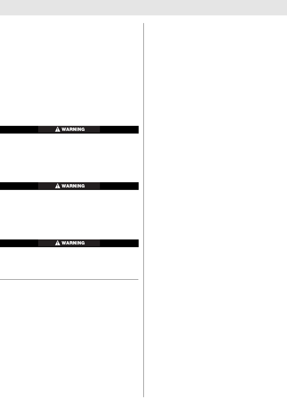
2. Use a fine-tip ink mark-
er and a ruler or
straight edge to draw a
line on the male cou-
pling. Make sure the
line extends across the
joint and coupling hex
flats onto the Audi-
Larm or Quick Fill man-
ifold body.
3. Put the dust cover on the coupling.
4. Grasp the dust cover by hand and, using maximum
effort, attempt to loosen the coupling at the joint by
turning the dust cover counterclockwise. Do not use
tools.
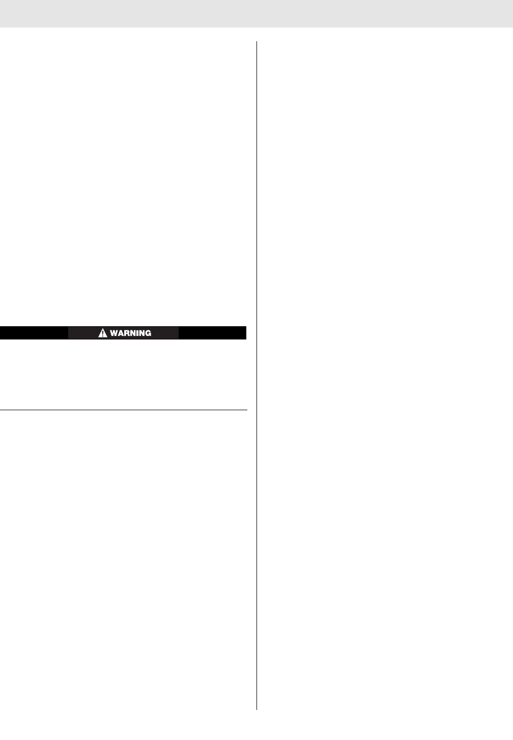
5. If the line does not line
up across the joint...
...or across the joint
where the coupling
attaches to the air
mask, remove the air
mask from service until
a replacement coupling
is installed. If the line
does line up, the cou-
pling is sufficiently tight
and the air mask may
be returned to service.
13 TAL 016 (L) Rev. 10 - 10082858 - DRAFT 7-21-10

NOTES
14
TAL 016 (L) Rev. 10 - 10082858 - DRAFT 7-21-10
DONNING
DONNING THE AIR MASK
1. Remove the facepiece from the case.
DO NOT use a cover lens in a high-temperature envi-
ronment, such as firefighting. High temperatures may
distort the cover lens. Or, moisture trapped between a
cover lens and the facepiece lens may condense and
distort vision. Always remove the cover lens before
donning the facepiece. Failure to follow this warning
can result in serious personal injury or death.
2. Ensure the the Audi-
Larm coupling nut is
hand-tight (no tools).
3. Ensure that the cylinder is fully pressurized.
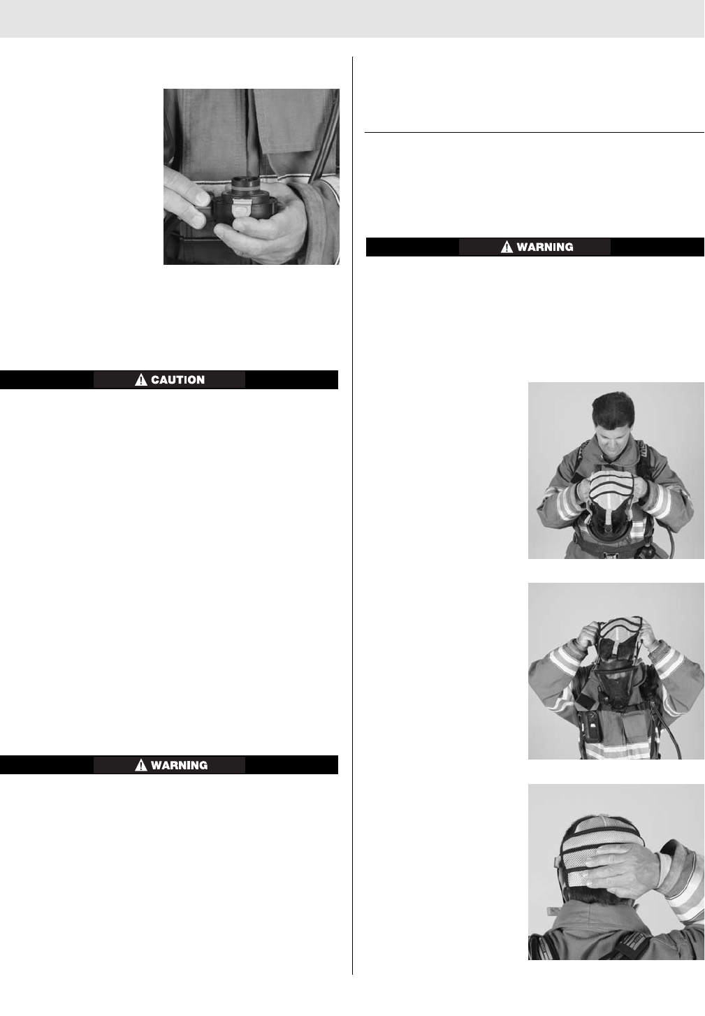
4. Reach the right arm inside the right shoulder straps
and grasp the NightFighter HUD Transmitter or
FireHawk M7 Control Module. Slide the left arm
through the left shoulder straps.
5. Bend forward slightly; resting the carrier on the back.
6. Attach the chest strap buckle (optional).
7. Fasten the waist belt and pull it tight for a snug fit.
Most of the air mask weight should be carried on the
hips.
8. Stand up straight. Pull the shoulder strap pull tabs out
to tighten the shoulder straps. Additional adjustments
to the waist belt may be needed.
9. The shoulder straps and waist strap ends must be
tucked in and lay flat across the body.
BEFORE USING THE AIR MASK
1. Grasp the Firehawk Regulator and push the side but-
tons.
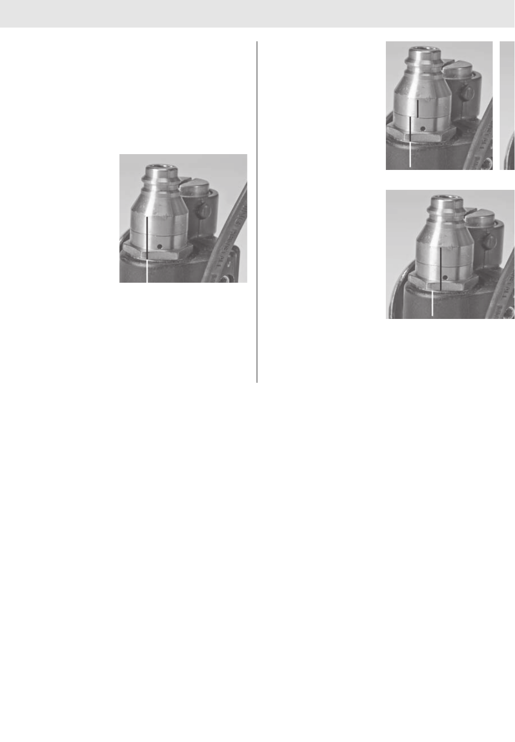
2. Ensure that the red
bypass knob is fully
closed (clockwise).
3. Reach behind and fully
open the cylinder valve.
Listen for any hiss or pop sounds from the Audi-Larm
Alarm, if heard, do not use the air mask. Return it to
an MSA trained or certified repairperson. Failure to
follow this warning can result in serious personal
injury or death.
4. As the system pressure rises from 50 to 200 psi, both
visible and audible alerts activate automatically, indi-
cating that the air mask is functioning properly. Such
alerts include a brief ring from the Audi-Larm Alarm, a
chirp from the FireHawk M7 Power Module (integrated
PASS version), and the start-up sequence of the
FireHawk M7 HUD LEDs.
DO NOT use the air mask if the Audi-Larm Alarm fails
to ring, the FireHawk M7 Power Module (integrated
PASS version) fails to sound, or the FireHawk M7 HUD
fails to light, The air mask must be checked and cor-
rected for proper operation by an MSA trained or cer-
tified repairperson before using. Failure to follow this
warning can result in serious personal injury or death.
5. No air should flow from
the Firehawk Regulator.
If it does, repeat steps
1 and 2.
6. Ensure the FireHawk M7 HUD and FireHawk M7 pres-
sure indicators show a full cylinder.
DO NOT use the air mask if the cylinder gauge and
FireHawk M7 pressure readings are not within 5%
(110/2216 psi, 150/3000 psi, 225/4500 psi) of full cylin-
15 TAL 016 (L) Rev. 10 - 10082858 - DRAFT 7-21-10
DONNING
der pressure. Send the unit to an MSA certified repair
person.
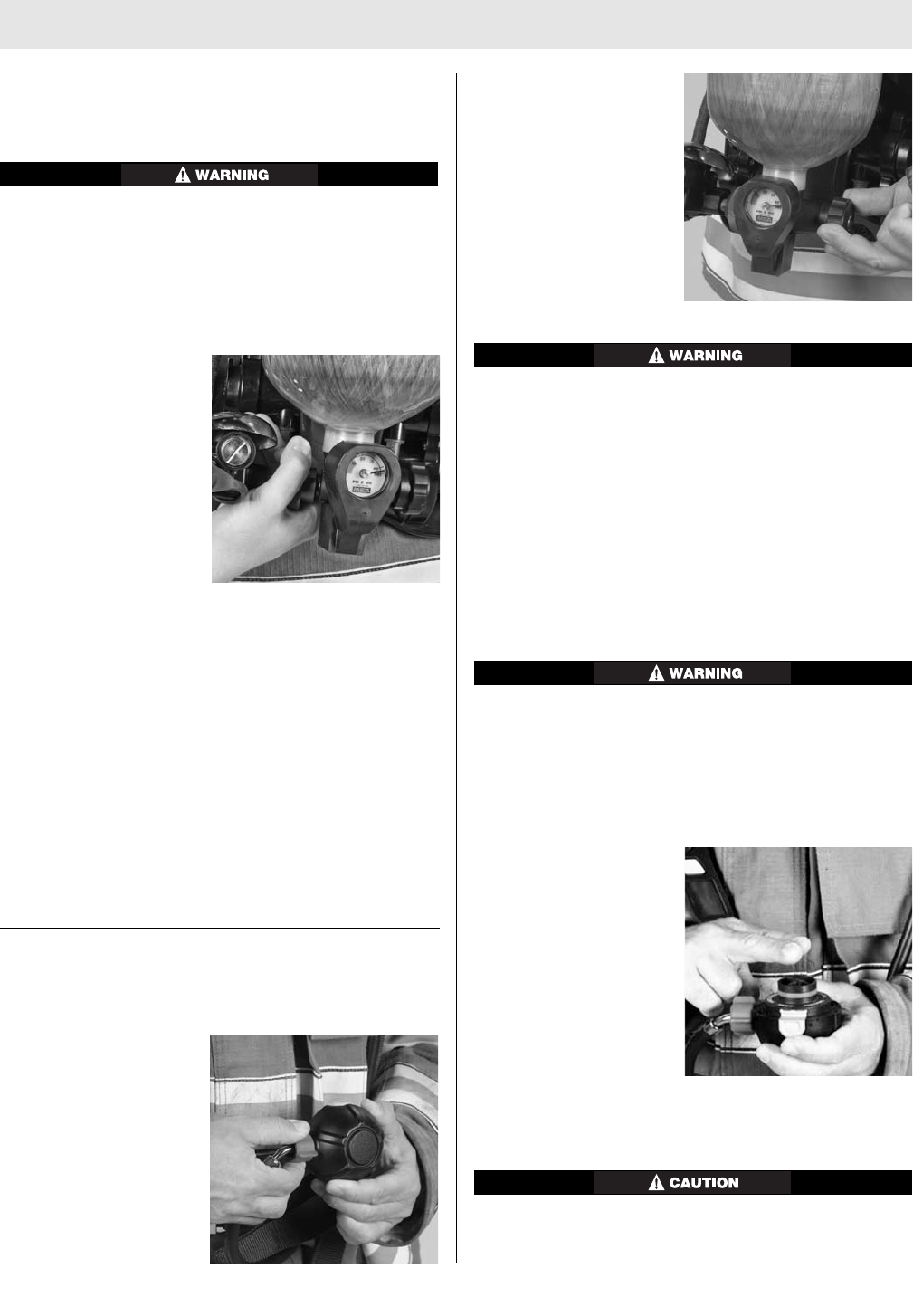
7. Check the Firehawk
Regulator’s bypass
operation. Grasp the
red knob and turn it
counter-clockwise.
Listen for airflow and
then turn it to the off
position.
8. Fully close the cylinder valve.
9. Listen for air leaks and watch the pressure gauge and
display on the FireHawk M7 Control Module (integrat-
ed PASS version) for 10 seconds.
DO NOT use the air mask if the pressure drops more
than 100 psi in ten seconds, The air mask must be
repaired; otherwise, reduced service life may result.
10. Crack the Firehawk Regulator bypass valve slowly to
bleed off pressure until the FireHawk M7 HUD and
FireHawk M7 pressure indicators drop below:
530 psi-approximately (2216 psi system)
750 psi-approximately (3000 psi system)
1125 psi-approximately (4500 psi system)
At these pressures the FireHawk M7 HUD should display
a flashing red LED, the Audi-Larm Alarm should ring con-
tinuously, and the alarm button on the FireHawk M7
Control Module (integrated PASS version) and the buddy
lights on the FireHawk M7 Power Module (integrated
PASS version) should be flashing red.
11. When the system pressure falls below 200 psi, turn
the FireHawk M7 Control Module off by depressing
the reset button (yellow) two times within approxi-
mately one second. (integrated PASS version)
DO NOT use the air mask if the Audi-Larm Alarm fails
to ring or fails to continuously ring down to pressures
of 200 psi, or if the FireHawk M7 Control Module (inte-
grated PASS version) or FireHawk M7 HUD (integrated
PASS version) fails to light properly. The air mask must
be checked and corrected for proper operation by an
MSA trained or certified repairperson before using.
Failure to follow this warning can result in serious per-
sonal injury or death.
Note: The FireHawk M7 HUD will automatically turn itself
OFF approximately 60 seconds after the air mask has
been depressurized. A single red LED will flash until the
device turns off.
DONNING THE FACEPIECE
Note: A nosecup is always required for use with this air
mask.
A nosecup must be installed in the facepiece. Failure
to follow this warning can result in serious personal
injury or death.
Note: Before donning, ensure that the Firehawk Regulator
sealing ring is seated properly in its groove on the outlet
of the regulator and that it is not torn, gouged, or nicked.
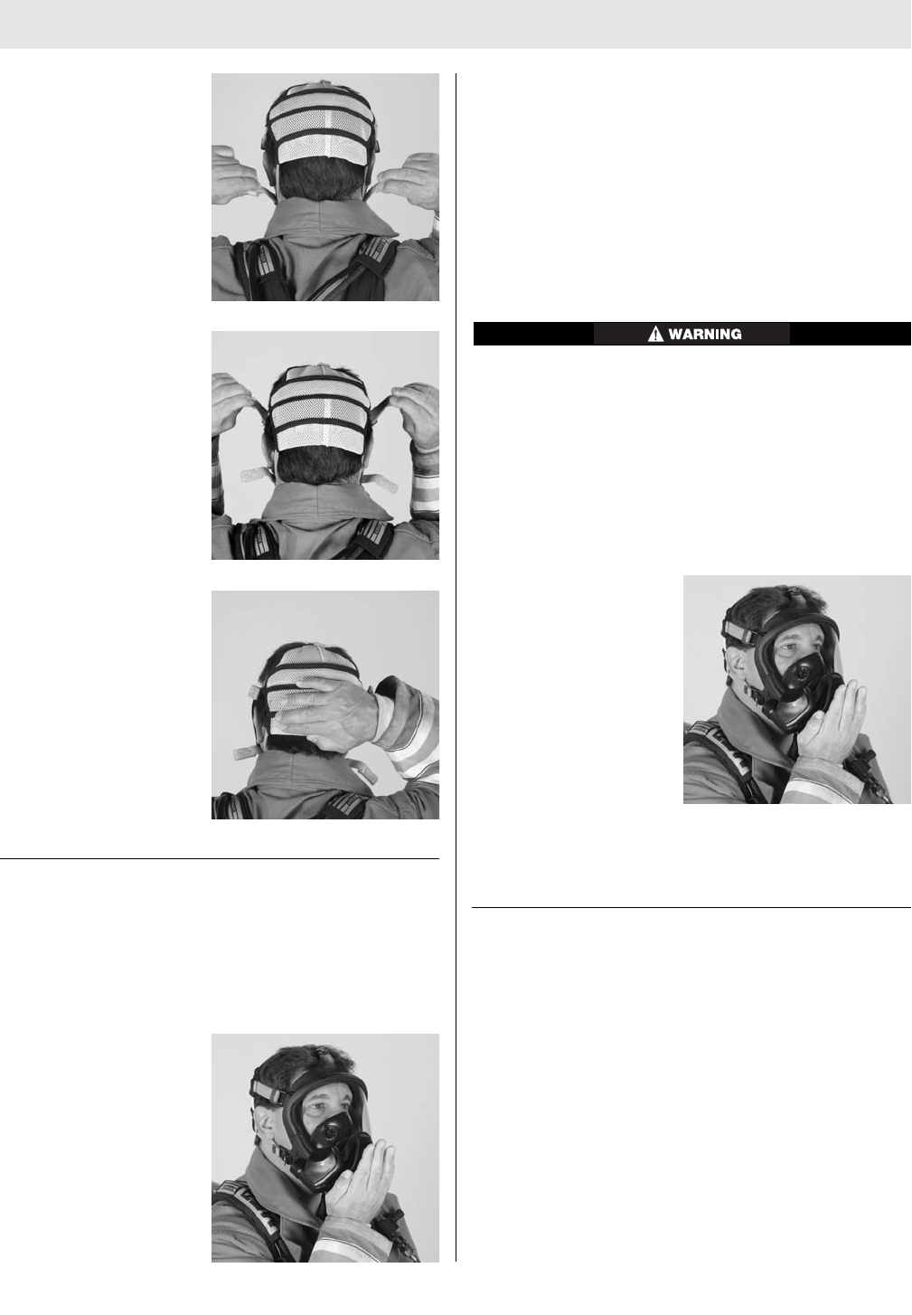
1. Loosen all the harness
straps. Grip the bottom
straps.
2. Insert chin into the
lower part of facepiece,
then pull the harness
back over the head.
3. Pull the back of har-
ness downward until
centered at the back of
the head.
16
TAL 016 (L) Rev. 10 - 10082858 - DRAFT 7-21-10
DONNING
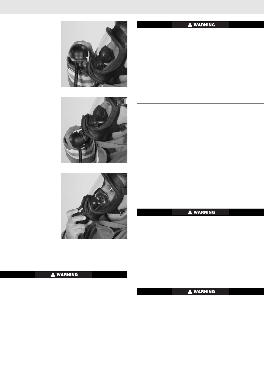
4. Tighten the two lower
straps first by pulling
them straight back, not
out. Tighten the face-
piece until the mask is
snug against the face.
5. Tighten the two side
temple straps in the
same manner as
described in step 4.
Ensure that the face-
piece tabs are not
tucked under the face
seal.
6. Ensure the back of the
harness is centered on
the back of the head
and that the facepiece
seal provides uniform
pressure on the face at
all points. Readjust the
straps if needed.
FACEPIECE FIT CHECK
Note: Check the inhalation valve by inhaling. If the face-
piece does not provide sufficient flow of air, do not use
facepiece. The facepiece must be repaired or replaced.
1. Check facepiece fit,
a. Hold the palm of the
hand over the face-
piece inlet adapter.
b. Take a deep breath
and hold it for at
least 10 seconds.
The facepiece
should collapse and
stay collapsed
against the face. If it
does not, readjust
the facepiece and
test again. If this does not correct the leak, do
not use the facepiece.
2. Test the exhalation valve.
a. Take a deep breath and hold it.
b. Block the facepiece inlet adapter with the palm of
the hand and exhale. If the exhalation valve is stuck,
a heavy rush of air around the facepiece may be
noticed. A sharp exhalation of air may be needed to
open the valve. If this does not release the valve, do
not use the facepiece.
This device may not seal properly to the face if a
beard, gross sideburns or similar physical characteris-
tics (see NFPA-1500 and ANSI Z88.2) exist. An improp-
er facial seal may allow contaminants to leak into the
facepiece, reducing or eliminating respiratory protec-
tion. Do not use this device if such conditions exist.
The face-to-facepiece seal must be tested before
each use. Never remove the facepiece except in a
safe, non hazardous non-toxic atmosphere. Failure to
follow this warning can result in serious personal
injury or death.
3. Open the cylinder valve
fully. Push in on the
side buttons of the
Firehawk Regulator to
stop air flow.
4. Listen for any hissing or popping sounds from the
Audi-Larm Alarm. If heard, return the air mask to an
MSA trained or certified repairperson.
INSTALLING THE SLIDE-TO-CONNECT FIREHAWK
REGULATOR ON THE FACEPIECE
Note: The slide-to-connect regulator has a side button
with a two pronged fork protruding from it. If this “fork” is
not present refer to the Installing the Push-To-Connect
Firehawk Regulator section of this manual.
17 TAL 016 (L) Rev. 10 - 10082858 - DRAFT 7-21-10
DONNING
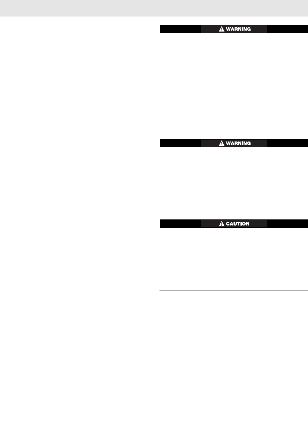
1. Grasp and orient the
regulator so that red
bypass knob is point-
ing to the right and
slide button is on top.
2. Slide the regulator onto
the rail of the facepiece
cover. Slide the regula-
tor down the rail until
the regulator stops.
3. Insert the regulator into
the facepiece inlet by
pushing inward.
4. Ensure proper engagement by pulling on the regulator
to verify that the regulator is securely attached to
facepiece.
DO NOT use the air mask unless the Firehawk
Regulator is connected properly. A regulator that is
not installed correctly can separate from the facepiece
unexpectedly. Return the air mask to an MSA trained
or certified repairperson to correct the condition.
Failure to follow this warning can result in serious per-
sonal injury or death.
5. Inhale sharply to start the airflow.
a. Check the bypass again by turning the red knob
counter-clockwise until feel increased airflow is felt.
Close the bypass.
There must be a continuous flow of air when the
bypass knob is opened. If not, do not use the air
mask. The air mask must be checked and the condi-
tion corrected by an MSA trained or certified repair-
person before it can be used. Failure to follow this
warning can result in serious personal injury or death.
Note: If the air mask passes all tests, it is ready for use.
These tests must be performed every time before entering
a hazardous atmosphere. If the air mask fails to meet any
of the tests, the condition(s) must be corrected before
using the air mask.
INSTALLING THE PUSH-TO-CONNECT FIREHAWK
REGULATOR
Note: There are two versions (slide-to-connect and push-
to-connect) of the Firehawk Regulator available for the
FireHawk M7 Air Mask. A slide-to-connect Firehawk
Regulator can be identified by examining the side buttons.
The slide-to-connect has a side button with a two
pronged fork protruding from it. If this “fork” is present,
refer to Installing the Slide-To-Connect Firehawk
Regulator section.
1. Grasp the Firehawk Regulator and insert the regulator
into the facepiece by pushing inward. Check proper
engagement by pulling on the regulator to ensure that
the regulator is securely attached to facepiece.
DO NOT use the air mask unless the regulator is con-
nected properly. A regulator that is not installed correct-
ly can separate from the facepiece unexpectedly. Return
the air mask to an MSA trained or certified repairperson
to correct the condition. Failure to follow this warning
can result in serious personal injury or death.
2. Inhale sharply to start the airflow.
3. Check the bypass again by turning the red knob
counter-clockwise until increased air flow is felt. Close
the bypass.
There must be a continuous flow of air when the
bypass knob is opened. If not, do not use the air
mask. The air mask must be checked and the condi-
tion corrected by an MSA trained or certified repair-
person before it can be used. Failure to follow this
warning can result in serious personal injury or death.
Note: If the air mask passes all tests, it is ready for use.
These tests must be performed every time before entering
a hazardous atmosphere. If the air mask fails to meet any
of the tests, the condition(s) must be corrected before
using the air mask.
18
TAL 016 (L) Rev. 10 - 10082858 - DRAFT 7-21-10
USING THE AIR MASK
PRECAUTIONS DURING USE
Note: If the breathing apparatus or any component fails,
malfunctions, or becomes damaged, contact MSA at 1-
800-MSA-2222 [1-800-672-2222] or email customer ser-
vice at info@MSAnet.com. SCBA products may be con-
sidered hazardous material. In addition, U.S. Department
of Transportation exceptions and approvals may apply to
SCBA products. Please contact customer service at
1-800-MSA-2222, or visit www.MSAnet.com/prism, for
more information.
Periodically check the pressure indicated on the FireHawk
M7 chest mounted pressure indicator.
• Air flow in the air mask is reduced: Immediately open
the Firehawk Regulator bypass. Immediately return to
fresh air.
• Air mask free-flows: Immediately return to fresh air.
• Audi-Larm Alarm Rings: Immediately return to fresh
air.
• FireHawk M7 HUD low pressure indicator lights and
flashes red: Immediately return to fresh air.
• FireHawk M7 Control Module (integrated PASS ver-
sion) alarm button flashes red: Immediately return to
fresh air.
Periodically check the pressure indicated on the FireHawk
M7 HUD and FireHawk M7 chest mounted pressure indi-
cator during use. The FireHawk M7 Control Module con-
tinually displays the cylinder pressure while the FireHawk
M7 HUD indicates when each quarter of the total cylinder
pressure has been reached for 20 seconds. When the
needle on the FireHawk M7 chest mounted pressure indi-
cator reaches the red zone on the gauge face the Audi-
Larm Alarm will begin ringing, the FireHawk M7 HUD will
display a single flashing red LED, and the alarm button on
the FireHawk M7 Control Module (integrated PASS ver-
sion) and buddy lights on the FireHawk M7 Power Module
(integrated PASS version) will flash red. When the Audi-
Larm Alarm starts ringing or when the pressure reaches
approximately 25% of the rated service pressure, return
to fresh air.
The FireHawk M7 HUD, FireHawk M7 Control Module
(integrated PASS version), and Audi-Larm Alarm indicate
when cylinder pressure drops below these approximate
values:
530 psi-approximately (2216 psi system)
750 psi-approximately (3000 psi system)
1125 psi-approximately (4500 psi system)
When the FireHawk M7 HUD, FireHawk M7 Control
Module (integrated PASS version), or Audi-Larm Alarm
indicates 25% cylinder pressure, immediately return to
fresh air.
Note: Air mask service life is greatly reduced when the
Firehawk Regulator bypass is used.
Leave the contaminated area immediately if:
• Breathing becomes difficult
• Dizziness or other distress occurs
• You taste or smell the contaminant
• You experience nose or throat irritation
• SCBA not functioning according to the
instructions or training
Failure to follow this warning can result in serious per-
sonal injury or death.
Note: See NIOSH Approval Label, Inserted in the Users
Instructions for complete list of CAUTIONS and LIMITA-
TIONS for the Respirator.
Misuse or abuse of the FireHawk M7 HUD, the
FireHawk M7 Control Module, FireHawk M7 Power
Module, NightFigher HUD Transmitter or the equip-
ment to which they are attached, or using this equip-
ment in a manner or situation not intended by the
manufacturer, may result in damage to the equipment
or may result in personal injury or death to user or
persons dependent on the user or damage to the
equipment.
• Always inspect the FireHawk M7 HUD, FireHawk
M7 Control Module, NightFighter HUD Transmitter
and FireHawk M7 Power Module for damage
before use. If damage is found, immediately
remove the device from service.
• DO NOT alter these components. Altering will void
the Intrinsic-Safety rating and may affect the
Intrinsic-Safety of the device.
FIREHAWK M7 HUD
FIREHAWK M7 HUD FUNCTIONALITY
1. The FireHawk M7 HUD allows the user to see the
cylinder pressure while wearing the air mask. The
FireHawk M7 Control Module or NightFighter HUD
Transmitter wirelessly transmits a signal to the
FireHawk M7 HUD (on the facepiece) while the air
mask is in use. The FireHawk M7 HUD displays the
cylinder pressure in one quarter cylinder increments,
by an LED pattern.
• As each quarter cylinder pressure has been
reached, a unique LED pattern will be displayed for
approximately 20 second before extinguishing. The
display can be refreshed by pressing and holding
the mode button (green) on the FireHawk M7
Control Module or NightFighter HUD Transmitter for
approximately three seconds.
19 TAL 016 (L) Rev. 10 - 10082858 - DRAFT 7-21-10
USING THE AIR MASK
20
TAL 016 (L) Rev. 10 - 10082858 - DRAFT 7-21-10
• When 25% of the rated service pressure has been
reached, a single flashing red LED will be displayed
and will continue to flash until the unit is turned off
or the cylinder has be refilled.
• The FireHawk M7 HUD must be within approximate-
ly 18 inches of the FireHawk M7 Control Module or
NightFighter HUD Transmitter to properly receive
the signal being transmitted.
2. The FireHawk M7 HUD has a buddy light that flashes
red when the air mask has reached 25% of the rated
service pressure. This buddy light is not visible to the
user while the air mask is in use.
3. When the user of the air mask remains motionless for
approximately 20 seconds, the PASS pre-alarm will
begin to sound (integrated PASS version). During this
pre-alarm, the FireHawk M7 HUD will display an
orange LED, and this LED will extinguish when full
PASS alarm has been reached or the pre-alarm has
been reset.
4. When an evacuation command has been sent to the
user (if the optional FireHawk M7 Telemetry Module is
in use), the FireHawk M7 HUD will display an alternat-
ing red and orange LED until the evacuation has been
confirmed.
5. The FireHawk M7 HUD has a photo sensor that auto-
matically adjusts the brightness of the LEDs based on
the intensity of the ambient light measured outside of
the facepiece.
6. The FireHawk M7 HUD indicates a low battery condi-
tion by a single flashing yellow LED. When the
FireHawk M7 Power Module reaches a low battery
condition, a double flash of the yellow LED will be dis-
played in the FireHawk M7 HUD. If both the FireHawk
M7 HUD and FireHawk M7 Power Module have
reached a low battery condition, the FireHawk M7
HUD will display an alternating single and double flash
of the yellow LED. If this condition exists, return to
fresh air, and replace the batteries immediately. See
Replacing Batteries in the FireHawk M7 HUD.
Refer to Chart 1 for a full description of all FireHawk M7
HUD LED patterns.
Replacing the Batteries in the FireHawk M7 HUD
Replace the batteries in the FireHawk M7 HUD when
the low battery LED flashes. Use only recommended
battery types. Change the batteries in a non-haz-
ardous area only. Failure to follow this warning can
result in serious personal injury or death.
1. Unthread the battery cap (counter-clockwise) on the
FireHawk M7 HUD battery tube.
2. Remove the battery cartridge from the FireHawk M7
HUD.
3. Remove the batteries and discard.
3. Inspect the battery cartridge for signs of damage such
R
GG
G
Y
G
G
G
G
Y
76% to 100%
Full Cylinder, 4 Green LED
20 Sec. Steadily ON
75% to 51%
3/4 Full Cylinder, 3 Green LED
20 Sec. Steadily ON
26% TO 50%
1/2 Full Cylinder, 2 Yellow LED
30 Sec. Flashing ON/OFF
25% to 0%
1/4 Full Cylinder, 1 Red LED
Flashing Continuously
Yellow LED, Low Battery LED
Single Flash - HUD
Double Flash - HUD Transmitter
Alternating Single/Double Flash -
Both HUD and HUD Transmitter
YR O
Orange LED for PASS Pre-Alarm
(integrated PASS)
Red/Orange LED for Evacuation Signal
Alternating Red/Orange
(telemetry module)
Chart 1: FireHawk M7 HUD LED Patterns
USING THE AIR MASK
as corrosion on the battery terminals or cracks in the
cartridge. If the battery cartridge is damaged, replace
the cartridge immediately.
4. Insert three AAA alkaline batteries in the appropriate
locations on the cartridge. Follow the notations on the
cartridge to ensure proper battery orientation.
Use only Rayovac 824 LR03, Rayovac Ultrapro LR03,
Energizer E92, Energizer Industrial EN92, Duracell
MN2400, or Duracell Procell PC2400 alkaline batteries
in the FireHawk M7 HUD. Use of other batteries, or a
combination of batteries from different manufacturers,
will affect the performance of unit and void the
Intrinsic Safety Approval.
5. Insert the battery cartridge into the battery tube on the
FireHawk M7 HUD.
6. Before installing the battery cap, verify that the o-ring
is in place and free of damage and debris. If the o-ring
is missing or damaged, replace o-ring. Failure to do so
may allow moisture or contaminants into the battery
tube and cause the device to not function properly.
7. Thread the battery cap on to the battery tube of the
FireHawk M7 HUD (clockwise). Hand-tighten cap until
snug. Do not over-tighten battery cap.
8. As the battery cap makes contact with the battery car-
tridge, verify that the FireHawk M7 HUD display turns
on and goes through its start up sequence before
turning off. The yellow LED should not be flashing.
Replacing the Batteries in the Nightfighter Transmitter
(without integrated PASS version)
Use only Rayovac 824 LR03, Rayovac Ultrapro LR03,
Duracell MN2400, Duracell Procell PC2400, Energizer
E92, or Eveready A92 AAA alkaline batteries in the
TRANSMITTER. Use of other batteries, or a combina-
tion of batteries from different manufacturers will void
the Intrinsic Safety approval. Failure to follow this
warning can result in serious personal injury or death.
1. Loosen the screws to open the battery doors in the
receiver.
2. Insert two AAA batteries according to the battery ori-
entation noted inside the receiver compartment.
3. Verify that the battery cover seal is present, not dam-
aged, and free of contamination.
4. Align the battery cover screws with the transmitter
housing
5. Tighten each screw evenly, alternating between
screws, until contact is made between the battery
cover seal and transmitter housing. Do not over tight-
en.
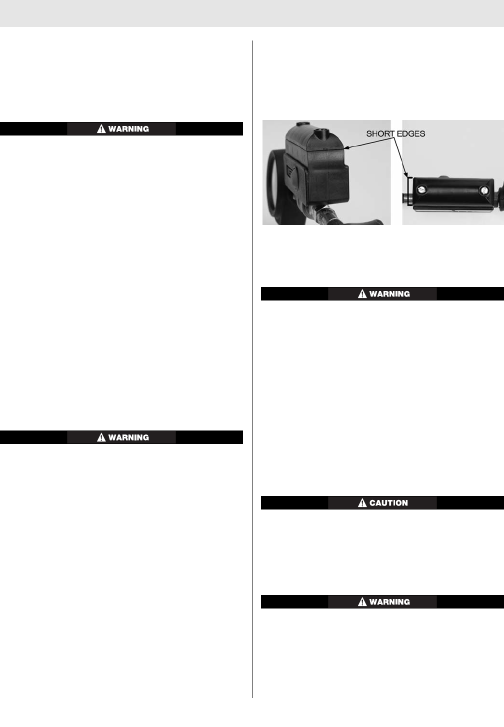
6. Continue to tighten each screw evenly, alternating
between screws, until both short edges of the battery
cover (see figure) completely contact the transmitter
housing.
7. Verify that the battery cover is properly assembled by
holding the transmitter up to a light source and
inspecting for gaps along the short edges (see figure).
The battery cover is properly installed when no light
can be seen along the short edges.
Battery Disposal/Recycling
Dispose of or recycle batteries in accordance with all
applicable federal, state, and local regulations.
DO NOT dispose of the batteries in fire. They may
explode. Failure to follow this warning can result in
serious personal injury or death.
Assembly of the FireHawk M7 HUD to the Facepiece
Bracket
Note: Assemble the FireHawk M7 HUD to the facepiece
bracket before donning the air mask.
With the facepiece lying on its side:
1. Align the metal tab on the FireHawk M7 HUD with the
metal plate on the front edge of the bracket.
2. Rotate the FireHawk M7 HUD so that the tab falls into
the slot behind the thumbscrew.
3. Thread the thumbscrew into the tab to finger-tight.
DO NOT use a screwdriver to tighten the thumbscrew.
Functional Tests
Note: Refer to the Visual Inspection and Functional Test
section of this manual.
Always test the FireHawk M7 HUD and the entire air
mask to be sure that the system operates properly
before entering any hazardous atmosphere. DO NOT
use this device unless it passes all inspection and
functional tests. Failure to follow this warning can
result in serious personal injury or death.
21 TAL 016 (L) Rev. 10 - 10082858 - DRAFT 7-21-10

USING THE AIR MASK
FIREHAWK M7 CONTROL MODULE FUNCTIONALITY
(INTEGRATED PASS VERSION)
• The FireHawk M7 Control Module is assembled to the
gauge line hose and is connected to the FireHawk M7
Power Module by the power cable. The FireHawk M7
Control Module serves as the user interface with the
air mask and it also serves as the wireless transmitter
for the FireHawk M7 HUD.
• The FireHawk M7 Control Module has three control
buttons.
o The RESET/OFF button (yellow) on the side of the
FireHawk M7 Control Module resets the PASS
device from the full alarm mode. It also shuts the
unit off after the cylinder valve has been closed and
all pressure is bled from the system. When the
optional FireHawk M7 Telemetry Module is used,
the Reset button allows the user to confirm an
evacuation command.
22
TAL 016 (L) Rev. 10 - 10082858 - DRAFT 7-21-10
ACTION VISIBLE/AUDIBLE INDICATOR VISIBLE INDICATOR,
without Thermal Alarm with Thermal Alarm CONTROL MODULE
automatic activation with
the system pressurized
manual activation
sensing mode (with or
without pressure
pre-alarm with
or without
pressure
full alarm (with or without
pressure)
deactivation
of full alarm
deactivation of pre-alarm
(with shake or move unit)
low battery
thermal alarm activation
(see thermal alarm activa-
tion curve)
radio link with
base station*
evacuation signal received*
redundant alarm (cylinder
pressure is below 25% of
rated service pressure
single rising tone with bee-
bop
start-up single rising tone
with bee-bop (also full
alarm)
none
low volume, low urgency
medium volume,
medium urgency
high volume, high urgency
full volume, high urgency
with a buzz
Bee
none
1 beep every 5 seconds
N/A
none
none
continuous beep beep
none
single rising tone with bee-
bop
start-up single rising tone
with bee-bop (also full
alarm)
none
low volume, low urgency
medium volume,
medium urgency
high volume, high urgency
full volume high urgency
with a buzz
Bee
none
1 beep every 5 seconds
1 beep every 3 seconds
none
none
continuous beep beep
none
green/red LED flash front
panel
green/red LED flash front
panel - red light flashing
green LED flashed
red LED flashes
red LED flashes
red LED flashes
green LED flashes
green LED flashes
empty battery icon on dis-
play
flashing thermometer icon
on display
radio link indicator icon in
upper left corner of display
radio link indicator icon dis-
appears
flashing “running man” icon
appears on display
red LED flashes
first 4 sec-
onds
(approx.)
second 4
seconds
(approx.)
last 4 sec-
onds
(approx.)
first push
of reset
button
second
push of
reset button
link is
established
out of
range
Chart 2: Audible/Visible Indicators, FireHawk M7 Power Module (integrated PASS version)
*Action only available when the FireHawk M7 Telemetry Module is used.
USING THE AIR MASK
o The center lighted ALARM button (green/red) acti-
vates the full PASS alarm with or without air pres-
sure.
o The top MODE button (green) will refresh the dis-
play in the FireHawk M7 HUD, activate the backlight
on the display of the FireHawk M7 Control Module,
set the FireHawk M7 HUD to continuous display
mode, and toggle the FireHawk M7 Control Module
digital display mode between pressure remaining
and calculated service time remaining. When the
FireHawk M7 Control Module is OFF, the mode but-
ton (green) can be used to scan an ID Tag into the
unit (when optional FireHawk M7 Telemetry Module
is used).
• The FireHawk M7 Control Module turns on automati-
cally when the user opens the air mask cylinder valve.
As the system pressure reaches approximately 200
psi, both visible and audible alarms activate automati-
cally, indicating that the unit is functional (audible
alarms are emitted from the FireHawk M7 Power
Module located on the backplate). The unit remains in
monitor mode until the user closes the cylinder valve,
purges the system pressure, and presses the reset
button (yellow) on the side of the FireHawk M7 Control
Module two times within approximately one second.
• While the air mask is in use, if the user is motionless
for approximately 20 seconds, the PASS (FireHawk
M7 Control Module and FireHawk M7 Power Module)
enters pre-alarm. During pre-alarm, the FireHawk M7
Power Module sounds 3 progressively louder tones
and the alarm button on the center of the FireHawk
M7 Control Module and buddy lights on the FireHawk
M7 Power Module slowly flash red. Also, during the
PASS pre-alarm, an orange LED will be displayed in
the FireHawk M7 HUD. Movement of the FireHawk M7
Control Module cancels the PASS pre-alarm.
• If the user remains motionless for 30 seconds (approx-
imately), the PASS enters full alarm. During full PASS
alarm, the FireHawk M7 Power Module repeatedly
sounds two high-pitched tones followed by a buzz.
During full PASS alarm the alarm button on the
FireHawk M7 Control Module and the buddy lights on
the FireHawk M7 Power Module rapidly flash red.
• The PASS can be set into full alarm at any time (even
without air pressure) by pressing and holding the
alarm button on the FireHawk M7 Control Module.
• The PASS function uses red and green LEDs behind
the alarm button of the FireHawk M7 Control Module
and buddy lights on the FireHawk M7 Power Module
to display its status visually:
o Green LEDs start to flash when the cylinder valve is
opened and shows that the device is operational.
o Red LEDs flash slowly when the device is in PASS
pre-alarm and flash rapidly when the device is in full
PASS alarm.
o Red LEDs flash when the cylinder pressure is at or
below 25% of the rated service pressure.
• The four C alkaline batteries in the FireHawk M7
Power Module supply the FireHawk M7 Control
Module with power. The system notifies the user when
the batteries need to be replaced by emitting an audi-
ble beep (1 beep every 5 seconds) from the FireHawk
M7 Power Module, displaying and empty battery icon
on the display of the FireHawk M7 Control Module,
and by a double flashing yellow LED on the FireHawk
M7 HUD.
• The FireHawk M7 Control Module has a data logging
feature that records information about the air mask
while the FireHawk M7 Control Module is turned on.
This data log memory can be accessed using the
FireHawk M7 Module.
• The FireHawk M7 Interface Module contains an inter-
nal real time clock. This clock can be reset using the
FireHawk M7 Control Module. By default, the internal
clock is set to Eastern Standard Time.
Before planning the FireHawk M7 Air Mask in service,
verify that the internal clock is set to the appropriate
time as per the user’s geographic location. Failure to
do so can result in inaccurate data logging of the
FireHawk M7 Control Module.
The time may be viewed or changed using the FireHawk
M7 Interface Module. For additional instructions on using
the FireHawk M7 Interface Module refer to the FireHawk
M7 Interface Module Instructions (P/N 10088977).
USING THE FIREHAWK M7 CONTROL MODULE
(INTEGRATED PASS VERSION)
Note: Refer to Chart 2 for the various audible and visual
indicators.
*Action only available when the FireHawk M7 Telemetry
Module is used.
FIREHAWK M7 CONTROL MODULE THERMAL ALARM
(INTEGRATED PASS VERSION)
The FireHawk M7 Control Module can monitor tempera-
ture conditions if the thermal alarm option is activated. If
the user is exposed to more than a pre-set limit of
time/temperature, the thermometer icon on the FireHawk
M7 Control Module display will flash and the FireHawk M7
Power Module will sound a tone every 3 seconds.
Although this thermal alarm provides an indication
that the time-temperature curve is exceeded, the
curve may not represent the threshold to injury due to
variations in individuals and the protective clothing
worn. Use this alarm as a reference only to increasing
time-temperature. Do not use as a substitute for stan-
dard operating procedures regarding escape from
23 TAL 016 (L) Rev. 10 - 10082858 - DRAFT 7-21-10
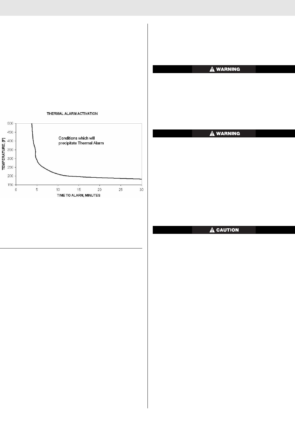
USING THE AIR MASK
time-temperature extremes. Failure to do so can result
in serious personal injury or death.
Chart 3 shows the FireHawk M7 Control Module thermal
alarm activation curve. The time/temperature limits corre-
spond to this graph. The thermal alarm sounds if the pre-
set limit exceeds the curve displayed on the graph. The
alarm will self-cancel depending on the severity of condi-
tions. This may occur even though the temperature is
above the thermal curve.
Chart 3: FireHawk M7 Control Module Thermal Alarm
Activation Curve
Note: This chart was generated from data obtained in a
laboratory setting and is for reference only. Conditions are
highly variable in an actual use scenario. Users of the
FireHawk M7 Control Module with the thermal alarm
option should develop procedures for the use of this fea-
ture.
DURING USE
Note: Refer to Chart 2 for the various audible and visual
indicators for the FireHawk M7 Control Module and
FireHawk M7 Power Module.
FireHawk M7 Control Module Pressure Display
(integrated PASS version)
1. Periodically check the pressure indicated on the
FireHawk M7 Control Module display. It will display
either remaining cylinder pressure (default) or calculat-
ed remaining service time.
2. When the pressure reaches 25% of the rated service
pressure, the alarm button on the FireHawk M7
Control Module will flash red and the FireHawk M7
HUD will display one flashing red LED.
3. When the pressure reaches approximately 25% of the
rated service pressure, return to fresh air.
Changing the FireHawk M7 Control Module Display
Mode (integrated PASS version)
1. Press the top mode button (green) once. This will
momentarily refresh FireHawk M7 HUD display as well
as light the FireHawk M7 Control Module display.
2. While the FireHawk M7 Control Module display is still
lit, press the top mode button (green) again. This will
toggle the display from remaining cylinder pressure to
calculated remaining service time.
The FireHawk M7 Control Module (integrated PASS
version has the ability to display calculated remaining
service time counting down to 0 psi (default) or 25% of
the rated service pressure. The user must determine
which option has been selected for the FireHawk M7
Control Module in service. Failure to follow this warn-
ing can result in serious personal injury or death.
Actual time remaining may be less than the calculated
time displayed. Increases in breathing rate may reduce
remaining time more than expected. Use time indica-
tor as general guide only. The time displayed is based
on the continuation of the average breathing rate over
the last three minutes. Increases in the breathing rate
after checking the displayed time may result in less
remaining time than anticipated. Failure to follow this
warning can result in serious personal injury or death.
Turning ON the Continuous Pressure Display Mode for
the FireHawk M7 HUD
In Continuous Pressure Display Mode, the life of the
batteries in the FireHawk M7 HUD will be shortened.
Note: The Continuous Pressure Display Mode can only be
activated when the system is pressurized.
1. Push the mode button (green) on the FireHawk M7
Control Module or NightFighter HUD Transmitter and
hold the button in for 3 seconds or until the FireHawk
M7 Power Module (integrated PASS version) sounds a
single beep. The LEDs will appear in the FireHawk M7
HUD.
2. The FireHawk M7 HUD will continuously show the
cylinder pressure.
Turning OFF the Continuous Pressure Display Mode
for the FireHawk M7 HUD
Note: The Continuous Pressure Display Mode will deacti-
vate if low battery in the FireHawk M7 HUD is reached.
1. With the FireHawk M7 HUD in Continuous Pressure
Display Mode, push the mode button (green) on the
FireHawk M7 Control Module (integrated PASS ver-
sion) or NightFighter HUD Transmitter and hold the
button in for 3 seconds or until the FireHawk M7
Power Modules sounds a single beep.
24
TAL 016 (L) Rev. 10 - 10082858 - DRAFT 7-21-10

USING THE AIR MASK
2. The FireHawk M7 HUD will revert to default mode
showing only cylinder pressure status at each 25%
increment of full cylinder pressure.
Low Battery Warnings
Replace the batteries in the FireHawk M7 Power
Module (integrated PASS version) when the low bat-
tery warning sounds. Use only recommended battery
types. Change the batteries in a non-hazardous area
only. Failure to follow this warning can result in seri-
ous personal injury or death.
Note: There are unique low battery warnings for the
FireHawk M7 HUD and the FireHawk M7 Power Module
(integrated PASS version) which are each displayed by the
FireHawk M7 HUD and on the FireHawk M7 Control
Module display (integrated PASS version).
1. If there is a low battery in the FireHawk M7 HUD, one
yellow LED will flash in the FireHawk M7 HUD.
2. If there is a low battery in the FireHawk M7 Power
Module or NightFighter HUD Transmitter, a double
flash of the yellow LED will be displayed.
3. If there are low batteries in the FireHawk M7 HUD and
FireHawk M7 Power Module or NightFighter HUD
Transmitter, the yellow LED FireHawk M7 HUD will
alternate single and double flashes of the yellow LED.
Replacing the Batteries in the FireHawk M7 Power
Module
DO NOT dispose of the batteries in fire. They may
explode. Failure to follow this warning can result in
serious personal injury or death.
Use only Rayovac 814 or AL-C (Regular/Max or
Ultrapro), Energizer E93, Energizer Industrial EN93,
Duracell MN1400, or Duracell Procell PC1400 alkaline
batteries in the FireHawk M7 Power Module. Use of
other batteries, or a combination of batteries from dif-
ferent manufacturers, will affect the performance of
unit and void the Intrinsic Safety Approval.
1. Unthread the battery cap on the FireHawk M7 Power
Module by rotating the battery cap in the counter-
clockwise direction.
2. Remove the four C batteries from the battery tube of
the FireHawk M7 Power Module.
3. Insert the four C batteries following the diagrams
inside the battery tube.
4. Verify that the o-ring on the battery cap is held in
place, free of damage and debris, and not twisted in
the gasket retention groove in the battery cap.
5. Install the battery cap on the FireHawk M7 Power
Module battery tube. Tighten the battery cap by rotat-
ing it clockwise until it is snug. Failure to fully install
the battery cap may prevent the battery tube from
being water tight.
6. Dispose of, or recycle batteries, in accordance with all
applicable federal, state, and local regulations.
Turning OFF the FireHawk M7 Control Module after
Doffing the Air Mask (integrated PASS version)
Turn the FireHawk M7 Control Module off after doffing
air mask; otherwise, batteries will be drained. The
FireHawk M7 Control Module does not shut off auto-
matically.
1. Upon returning to fresh air, close the cylinder valve
completely and release all pressure from the air mask.
2. When the pressure falls below 200 psi, turn the
FireHawk M7 Control Module off by pressing the reset
button (yellow) two times within approximately one
second.
a. The FireHawk M7 Power Module will beep once
when the reset button is pressed once. Pressing the
reset button a second time will then sound three
beeps (“bee-bop-bop”) to indicate that the unit is
turned off. The lights on the FireHawk M7 Control
Module and FireHawk M7 Power Module will stop
flashing.
25 TAL 016 (L) Rev. 10 - 10082858 - DRAFT 7-

COLD WEATHER OPERATION
Suggested Procedures for Cold Weather Operation
Moisture can cause problems in the air mask if it freezes.
However, moisture can cause freezing problems even if
the surrounding air is above freezing. Air flowing from the
cylinder through the first and second stage regulators
drops from cylinder pressure to close to atmospheric
pressure very quickly. This causes the air to expand and
creates a cooling effect. Although the surrounding tem-
perature may be warmer than 32°F, the temperature inside
the regulator may be lower. Any water inside could turn to
ice and restrict airflow.
1. To keep moisture from entering the mask mounted
regulator, keep the Firehawk Regulator in the belt
mounted regulator holder when not in use.
2. When the air mask is away from heat, water spray can
freeze on the Firehawk Regulator surface. Ice can
build up and bind the side buttons or the bypass
valve. Before entering or re-entering a hazardous
atmosphere, ensure the side buttons and bypass valve
are ice-free and operating properly. Periodically check
the bypass to be sure it is ice-free.
3. Moisture can enter through the cylinder valve or cou-
pling nut when cylinders are replaced on the air mask.
When replacing cylinders, ensure moisture or contami-
nation does not enter the system. Remove any ice
from these fittings. Wipe the coupling nut threads and
cylinder valve threads before installing a new cylinder.
Water can contaminate the system and freeze.
4. When cleaning the air mask, ensure water does not
enter the facepiece or Firehawk Regulator.
5. Thoroughly dry the facepiece and mask mounted reg-
ulator after cleaning and disinfecting. Follow
Confidence Plus® Cleaning Solution instructions.
Note: Fresh batteries must be installed in the FireHawk
M7 HUD, FireHawk M7 Power Module, and NightFighter
HUD Transmitter prior to storage of the Air Mask at cold
temperature for an extended period of time.
26
TAL 016 (L) Rev. 10 - 10082858 - DRAFT 7-21-10

AUDI-LARM ALARM WITH URC ASSEMBLY
URC (UNIVERSAL RESCUE CONNECTION) ASSEMBLY
All NFPA 1981, 2007 Ed. approved air masks are
equipped with a URC Assembly (Universal Rescue
Connection) fitting. The URC Assembly is a male quick-fill
inlet for use by Rapid Intervention Crews for emergency
filling operations. The system also includes an automati-
cally resetting pressure relief valve. The air mask can also
be equipped with a shoulder mounted Quick-Fill System,
unless using a 3000 psi URC Assembly, the 3000 psi URC
Assembly can not be used with Quick-Fill System. For
additional information on using the Quick-Fill System,
refer to the Quick-Fill System section of the manual.
The URC Assembly may be used for transfill operations
as described in this manual. Only qualified, trained per-
sonal Standard Operating Procedures should be devel-
oped for use of the URC Assembly.
PRECAUTIONS FOR USING THE URC ASSEMBLY
1. The URC Assembly can only be used to fill approved
air mask cylinders.
2. The URC Assembly is not to be used as a "Buddy
Breather" such that two users are sharing the air sup-
plied by one air mask cylinder simultaneously doing so
will void NIOSH approval.
3. The user is responsible for the air supply, which must
meet the requirements of Compressed Gas
Association Specification ANSI/G-7.1, Quality
Verification Level (Grade) D Gaseous Air or better, with
a moisture dew point of not greater than -65°F
(24ppm water vapor, normal). In fire service applica-
tions, MSA recommends breathing air quality in accor-
dance with NFPA 1989. Pressures at the inlet of the
quick-fill hose must not exceed that of the air mask
(2216 psi or 4500 psi).
4. Using the 3000 psi URC Assembly to fill cylinders: The
cylinder can only be filled to 2216 psi. If the pressure
exceeds 2216 psi a relief valve in the URC Assembly
will vent at approximately 2525 psi or as low as 2400
psi. A 3000 psi cylinder can only be filled to 3000 psi
by using a secondary air supply; the 3000 psi URC
Assembly cannot be used for filling a 3000 psi cylinder.
5. The user also is responsible for connecting the quick-
fill hose to an appropriate secondary air supply.
6. The cylinder must be inspected for damage before
charging.
7. If filling cylinders in fresh air using the URC Assembly
topping off the cylinder is recommended after the
cylinder has cooled from initial fill. Topping off a cylin-
der after it has cooled will ensure proper service time.
• DO NOT use the URC Assembly as a "Buddy
Breather" such that two users are sharing the air
supplied by one approved air mask cylinder simul-
taneously; doing so will void NIOSH approval.
• The URC Assembly must be used by trained Rapid
Intervention Crews only using procedures devel-
oped for rapid intervention.
• DO NOT install a Quick-Fill System and 3000 psi
URC assembly on the same air mask. Combining
these assemblies on the same air mask will not
allow the relief valve in the 3000 psi URC Assembly
to open as designed. Failure to follow this warning
can result in serious personal injury or death.
• DO NOT transfill (be a donor) using a 3000 psi URC
Assembly. The 3000 psi URC Assembly has a
check valve that does not allow cylinders to trans-
fill (be a donor).
• Using the 3000 psi URC Assembly to fill cylinders:
The cylinder can only be filled to 2216 psi. If the
pressure exceeds 2216 psi a relief valve in the URC
Assembly will vent at approximately 2525 psi or as
low as 2400 psi. A 3000 psi cylinder can only be
filled to 3000 psi by using a secondary air supply;
the 3000 psi URC Assembly cannot be used for fill-
ing a 3000 psi cylinder.
• DO NOT lubricate the URC Assembly fittings. Do
not permit oil, grease, or other contaminants to
come in contact with the quick-fill fittings.
• The hose assemblies and fittings are designed to
be used with Quality Verification Level (Grade) D or
better air as defined by ANSI/CGA G-7.1.TRANS-
FILLING AIR FROM A SECONDARY AIR SUPPLY. In
fire service applications, MSA recommends breath-
ing air quality in accordance with NFPA 1989.
Failure to follow the above warnings can result in seri-
ous personal injury or death.
Note: The URC Assembly may be used for transfill opera-
tions as described in this manual. Standard operating pro-
cedures should be developed for use of the URC Assembly.
The URC Assembly must be used only by qualified, trained
personnel who have carefully read and understood these
instructions, cautions, and warnings. NIOSH approvals of
SCBA from MSA are maintained while transfilling air only if
appropriate hose assemblies from MSA are used. URC
Assembly or hose assemblies and fittings are rated for a
maximum working pressure of 4500 psi. NIOSH approval
is maintained only when using the following hose assem-
blies: 485331, 802687, 802688, 802689, 802690, and
48332, for filling cylinders in IDLH atmospheres.
27 TAL 016 (L) Rev. 10 - 10082858 - DRAFT 7-21-10

AUDI-LARM ALARM WITH URC ASSEMBLY
FILLING INSTRUCTIONS FOR USING THE URC
ASSEMBLY
A secondary air supply stores compressed breathing air
until needed to refill air mask air cylinders. When transfill-
ing, the secondary air supply pressure must be greater
than air mask cylinder pressure. Examples of air supplies
include: cascade air cylinder refilling systems; high pres-
sure compressor systems with a fixed reservoir; or a
portable air system such as the RescueAire™ System.
DO NOT connect a high pressure air mask to a sec-
ondary air supply with a pressure greater than 4500
psi. The high pressure air mask is rated for a maxi-
mum working pressure of 4500 psi. Failure to follow
the above warnings can result in serious personal
injury or death.
Note: Rapid Intervention Crews should use a separate air
supply such as MSA’s RescueAire portable air supply sys-
tem to fill the air mask in an IDLH atmosphere.
1. Connect the quick-fill hose to the secondary air sup-
ply.
a. Turn the air supply on.
If there are leaks from either female fitting, or along
the hose, depressurize the hose and correct the prob-
lem. Such leakage can result in increased fill time.
2. Attach the quick-fill hose to the URC Assembly.
a. Remove the rubber dust cap from the male inlet fit-
ting on the URC Assembly. Be sure that the cylinder
valve is fully opened.
b. Remove the rubber dust cap from the female fitting
on the quick-fill hose.
c. Push the female fitting of the hose onto the male fit-
ting of the URC Assembly until it snaps in place.
Pull on the hose to be sure the connection is
secure. Filling immediately begins when the female
fitting fully engages with the URC Assembly.
d. After approximately 45-60 seconds, the pressure
between the secondary air supply and the air mask
cylinder will be equal.
If serious leakage is noticed from either of the two
female fittings, or anywhere along the hose, discon-
nect the female fittings and return to fresh air immedi-
ately. Failure to follow this warning can result in seri-
ous personal injury or death.
Note: If the secondary air supply does not have a suffi-
cient volume of air, the air mask cylinder will not reach full
service pressure.
3. Compare the cylinder pressure gauge or the FireHawk
M7 Control Module reading (integrated PASS version)
to the secondary air supply pressure gauge reading. If
the readings are the same, pressure is equal.
4. To disconnect the quick-fill hose after transfilling, pull
the gray sleeve back. The hose fitting and the URC
Assembly will separate. A hiss or pop may be heard
as the fittings separate and the high pressure air is
sealed off.
5. Immediately install the dust cover on the URC
Assembly.
6. The air mask cylinder is ready for service if the cylin-
der pressure gauge needle is on the appropriate color
band.
TRANSFILLING BETWEEN AIR MASKS
Note: The air mask with the higher pressure reading is the
donor. The air mask with the lower pressure is the receiv-
er. Transfilling between users of air mask should be per-
formed only during life-threatening emergencies or simu-
lated training exercises. Both donor and receiver must
return to fresh air immediately following the procedure.
DO NOT transfill if the donor's audible alarm is ringing
or FireHawk M7 HUD /FireHawk M7 Control Module
(integrated PASS version) are flashing. Failure to fol-
low this warning can result in shorter escape time to
return to fresh air, causing serious personal injury or
death.
28
TAL 016 (L) Rev. 10 - 10082858 - DRAFT 7-21-10

AUDI-LARM ALARM WITH URC ASSEMBLY
The audible alarm begins ringing and heads-up display
system begins flashing to indicate that the pressure in the
cylinder has been reduced to 25% of its rated working
pressure. Remaining service time must be used for
escape to fresh air. If the donor's audible alarm begins
ringing or FireHawk M7 HUD/FireHawk M7 Control
Module (integrated PASS version) begins flashing during
transfilling, the donor should disconnect and preserve his
escape time.
1. If the donor's alarm is not ringing and FireHawk M7
HUD/FireHawk M7 Control Module (integrated PASS
version) are not flashing and you have sufficient air to
transfill to a receiver, (greater than 1000 psi for 2216
psi air masks and greater than 2000 psi for 4500 psi
air masks), follow these steps.
a. Remove the 3 foot emergency transfill hose from its
protective pouch.
b. Remove the rubber dust cover from both female fit-
tings on the transfill hose assembly.
c. Remove the rubber dust cover from the URC fitting.
d. Push the female fittings on to the male fittings until
they click in place. Pull on the hose to be sure it
snapped in place.
If serious leakage is noticed from either of the two
female fittings, or anywhere along the hose, discon-
nect the female fittings and return to fresh air immedi-
ately. Failure to follow this warning can result in seri-
ous personal injury or death.
e. After approximately 45-60 seconds, pressure
between the air mask cylinders will be equal.
f. Disconnect the transfill hose from the air mask by
pulling the gray sleeve back on both ends. A hiss or
pop may be heard as the fittings separate and the
high pressure air is sealed off.
g. Immediately install the dust cover on the URC fit-
ting. The dust cover prevents dirt, water, and debris
from entering the fitting, and acts as a redundant
seal.
URC ASSEMBLY LEAKAGE
1. When transfilling in fresh air and the dust cover will
not stay on the male fitting because air is leaking, cor-
rect the condition before using the air mask.
2. When transfilling in a contaminated atmosphere and
the dust cover will not stay on the male fitting because
air is leaking:
a. Immediately reconnect the quick-fill hose to seal off
the leak and return to fresh air.
b. If the hose will not reconnect, reach behind and
close the cylinder valve. Air pressure in the regulator
will drop, and the leak will slow down.
c. Quickly replace the protective dust cap on the male
fitting. This will form a redundant seal.
d. Open the cylinder valve and return to fresh air
immediately. The dust cover prevents dirt, water,
and debris from entering the fitting, and acts as a
redundant seal.
EMERGENCY TRANSFILL HOSE STORAGE
1. Preparing the Emergency Transfill Hose for storage:
a. Press in on the center of the quick-disconnect dust
cap to release any pressure in the transfill hose.
b. Roll up the hose and place it in its protective pouch.
29 TAL 016 (L) Rev. 10 - 10082858 - DRAFT 7-21-10

NOTES
30
TAL 016 (L) Rev. 10 - 10082858 - DRAFT 7-21-10
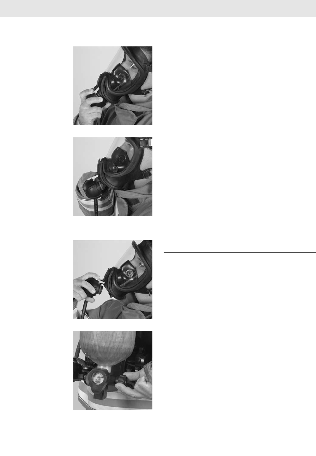
REMOVING THE AIR MASK
DISCONNECTING THE SLIDE-TO-CONNECT
FIREHAWK REGULATOR
1. Grasp the top of the
regulator.
2. Push the side release
buttons and pull the
regulator down and out
of facepiece.
Note: The regulator can hang on cover rail in a stand-by
mode.
3. Slide the regulator up
the cover rail until the
regulator slide button is
free of the cover rail.
4. Close the cylinder
valve fully. Open the
Firehawk Regulator
bypass to release sys-
tem pressure. Close
the bypass.
5. When the pressure falls below 200 psi, turn the
FireHawk M7 Control Module (integrated PASS ver-
sion) off by pressing the reset button (yellow) two
times within approximately one second.
Note: FireHawk M7 HUD will automatically turn itself OFF,
approximately 60 seconds after the air mask has been
depressurized. (The single red LED will flash until the
FireHawk M7 HUD turns off)
6. Stow the Firehawk Regulator, oriented with the slide
button facing down in the belt mounted holder when it
is not in use.
7. To remove the facepiece, fully loosen the harness
straps and pull the facepiece up and away from the
face.
8. To remove the carrier and harness, press the waist
belt buckle release button IN.
9. Disconnect the chest strap buckle (if used).
10. To loosen the shoulder straps, grasp the pull tabs and
push them out and away from the body.
11. Slip the right arm out of the shoulder strap first, and
then remove the harness.
Note: Be sure to replace the cylinder with a fully charged
one. Complete Inspection and Cleaning and Disinfecting
Procedures outlined in this manual. Ensure that the com-
plete SCBA is clean and dry. Ensure that facepiece head
harness straps and harness adjustment straps are fully
extended. Place the complete air mask in the storage
case or suitable storage location so that it can be easily
reached for emergency use. (See storage instructions.)
DISCONNECTING THE FIREHAWK
PUSH-TO-CONNECT REGULATOR
1. Grasp the top of the regulator.
2. Push the side release buttons and pull the regulator
out of facepiece.
3. Close the cylinder valve fully. Open the Firehawk
Regulator bypass to release system pressure. Close
the bypass.
4. When the pressure falls below 200 psi, turn the
FireHawk M7 Control Module (integrated PASS ver-
sion) off by depressing the reset button (yellow) two
times within approximately one second.
Note: The FireHawk M7 HUD will automatically turn itself
OFF, approximately 60 seconds after the air mask has
been depressurized. (A single red LED will flash until the
FireHawk M7 HUD turns off)
5. Stow the Firehawk Regulator in the belt mounted
holder when it is not in use.
6. To remove the facepiece, fully loosen the harness
straps and pull the facepiece up and away from the
face.
7. To remove the carrier and harness, press the waist
31 TAL 016 (L) Rev. 10 - 10082858 - DRAFT 7-21-10
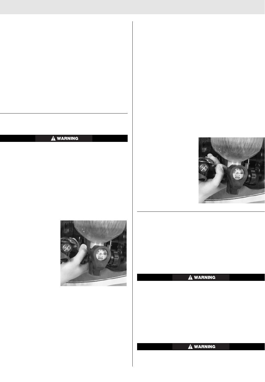
REMOVING THE AIR MASK
belt buckle release button IN.
8. Disconnect the chest strap buckle (if used).
9. To loosen the shoulder straps, grasp the pull tabs and
push them out and away from the body.
10. Slip the right arm out of the shoulder strap first, then
remove the harness.
Note: Be sure to replace the cylinder with a fully charged
one. Complete Inspection and Cleaning and Disinfecting
Procedures outlined in this manual. Ensure that the com-
plete SCBA is clean and dry. Ensure that facepiece head
harness straps and harness adjustment straps are fully
extended. Place the complete air mask in the storage
case or suitable storage location so that it can be easily
reached for emergency use. (See storage instructions.)
CHANGING THE CYLINDER
DO NOT drop the cylinder or bump the cylinder valve
knob. An unsecured cylinder can become an airborne
projectile under its own pressure if the valve is opened
even slightly. Failure to follow this warning can result
in serious personal injury or death.
1. Ensure there is no pressure in the system before
replacing a cylinder.
2. Close the cylinder valve.
3. Turn the Firehawk Regulator bypass counter-clockwise
until air no longer discharges from the regulator.
4. Close the bypass by turning the knob clockwise.
5. Disconnect the Audi-
Larm Alarm coupling
nut.
6. Lift and turn the latch wing to loosen the cylinder
clamp.
7. Slide the empty cylinder out of the carrier and install a
fully charged cylinder. Be sure that the adjustable
cylinder band and latch is in the proper slot before
inserting a new cylinder.
8. Slide the fully charged cylinder into the carrier, with
gauge facing out. Turn the latch wing clockwise 180
degrees until it stops. Fold the latch wing toward
backplate, locking latch wing in place.
Note: Be sure to completely tighten the latch wing each
time a cylinder is installed.
9. To check that the cylinder is secure, place one hand on
the backplate and grasp the cylinder valve with the
other hand. Try to pull the cylinder and valve down and
out away from the carrier. Make sure that the band and
latch holds the cylinder securely in the carrier.
Note: If the cylinder feels loose, remove the cylinder and
check that the latch engages with the proper slot on the
band. Re-install the cylinder and ensure that the latch
wing is fully tightened and flipped over. Do not use the air
mask if the cylinder is not held securely in the carrier.
10. Before installing the Audi-Larm Alarm, check that the
o-ring inside the Audi-Larm Alarm coupling nut is pre-
sent and free of damage. If the o-ring is damaged, it
must be replaced before the alarm is used.
11. Thread the Audi-Larm
Alarm coupling nut on
to the cylinder valve
thread form and hand-
tighten (no tools).
CHARGING CYLINDERS
A lightweight SCBA cylinder can become airborne solely
under the thrust of air from an inadvertedly opened cylin-
der valve. If a cylinder is removed from a horizontal shelf
by grasping the handwheel, the weight of the cylinder can
cause the cylinder to rotate downward causing the valve
to open slightly.
• Never carry a cylinder by the handwheel.
• Avoid dropping the cylinder or bumping the hand-
wheel.
• Use the handwheel only to open and close the
cylinder valve.
A valve could partially open causing the cylinder to
become an airborne projectile under its own pressure and
result in serious personal injury or death.
1. Remove from service if cylinder shows evidence of
exposure to high heat or flame: e.g., paint turned
32
TAL 016 (L) Rev. 10 - 10082858 - DRAFT 7-21-10

REMOVING THE AIR MASK
to a brown or black color, decals charred or miss-
ing, gauge lens melted, or elastomeric materials
distorted.
2. Use this device only after receiving proper training
in its use. Use in accordance with this label and
MSA apparatus instructions.
3. To maintain NIOSH approval, the cylinder must be
fully charged with respirable air meeting the
requirements of the Compressed Gas Association
specification G-7.1 1989 for Quality Verification
Level (grade) D air or equivalent specification. In
fire service applications, MSA recommends breath-
ing air quality in accordance with NFPA 1989.
4. Do not use unless the cylinder is filled to the maxi-
mum working pressure.
5. Do not alter, modify, or substitute any components
without approval of the manufacturer.
6. Inspect frequently. Maintain according to manufac-
turer’s instructions. Repair only by properly trained
personnel.
Failure to follow these warnings can result in serious
personal injury or death.
SAFETY PRECAUTIONS FOR MSA SELF-CONTAINED
BREATHING APPARATUS CYLINDERS
Breathing apparatus cylinders should be fully recharged
as soon as possible after use.
Cylinders should not be stored partially charged:
1. If used partially charged, the duration of the air mask
is reduced.
2. The pressure relief device is only designed to protect
a fully charged cylinder from the effects of a fire.
For maximum safety, the cylinders should be stored full or
at a pressure above ambient but less than 100 psi.
Prior to recharging, cylinders must be examined externally
for evidence of high heat exposure, corrosion, or other
evidence of significant damage.
Additional information of value when performing external
and internal inspections of cylinders may be found in the
latest editions of CGA Publication C-6: "Standards for
Visual Inspection of Steel Compressed Gas Cylinders",
CGA Publication C-6.1: "Standards for Visual Inspection
of High Pressure Aluminum Compressed Gas Cylinders",
and/or CGA Publication C-6.2: "Guidelines for Visual
Inspection and Requalification of Fiber Reinforced High
Pressure Cylinders" available form the Compressed Gas
Association, Inc., 1725 Jefferson Davis Highway, Suite
1004, Arlington, VA 22202-4102.
If there is any doubt about the suitability of the cylinder
for recharge, it should be returned to a certified hydrostat-
ic test facility for expert examination and testing.
Always check to be sure the retest date is within the pre-
scribed period and that the cylinder is properly labeled to
indicate its gaseous service. New labels are restricted
items which are not available except through certified
hydrostatic test facilities.
When replacing cylinder valves or after the retesting of
cylinders, make sure the proper cylinder valve, burst disc,
and o-ring are installed prior to cylinder recharging.
Determine the maximum service pressure of the cylinder.
Type 3 AA (steel) cylinders that bear a plus (+) sign after
the latest retest date may be recharged to a pressure, i.e.
a cylinder stamped 3AA2015 with a plus (+) sign after the
test date may be recharged to 2216 psi. (this applies to
steel cylinders only). Steel cylinders without the plus (+)
sign stamped after the latest test date must be removed
from service. All other cylinders which are not 3AA type
shall be filled to the designated service pressure only (as
found on the DOT approval or stamping). For cylinders
manufactured under a U.S. DOT exemption (i.e., DOT-E-
#####), the exemption should be consulted and is avail-
able from the Associate Administrator for Hazardous
Materials Safety, Research and Special Programs
Administration, U.S. Department of Transportation, 400
7th Street, SW, Washington, D.C. 20590-0001.
Appropriately connect the cylinder to the filling system
and refill. Terminate the filling when the pressure reaches
the maximum service pressure and allow the cylinder to
cool to room temperature. If necessary, top-off the cylin-
der such that the service pressure is attained with the
cylinder at a temperature of 70°F. Close the valves on the
cylinder and the filling system and remove the cylinder.
Apply a leak solution to determine if there is any leakage
between the cylinder and the valve. If there is no leakage,
the cylinder is ready for use.
STORAGE
Do not store the air mask or spare cylinders within or near
an area where the air mask can or might be exposed to
any substances that will or might attack any part of the air
mask, causing the air mask to not perform as designed
and approved.
Prior to storing the air mask in a jumpseat, ensure there is
no interference between the air mask and the seat.
DO NOT drop the cylinder or bump the valve knob. An
unsecured cylinder can become an airborne projectile
under its own pressure if the valve is opened even
slightly. Failure to follow this warning can result in
serious personal injury or death.
Do not store the air mask for extended periods with the
batteries installed in the electronic components if the air
33 TAL 016 (L) Rev. 10 - 10082858 - DRAFT 7-21-10

REMOVING THE AIR MASK
mask is not intended for service. If the air mask is in ser-
vice, ensure that the batteries in the electronic compo-
nents have an adequate charge. Do not store the air mask
with an empty or partially filled cylinder. Always install a
fully-charged cylinder so that the air mask is ready for
use. Complete Inspection and Cleaning and Disinfecting
Procedures outlined in this manual. Ensure the entire air
mask is clean and dry. Ensure the facepiece head harness
adjustment straps are fully extended. Place the complete
air mask in the storage case or suitable storage location
so it can be easily reached for emergency use.
For prolonged storage of the air mask, remove the batter-
ies from all electronic components to prevent battery cor-
rosion. Store the units in a cool, dry place.
Note: Fresh batteries must be installed in the FireHawk
M7 HUD, FireHawk M7 Power Module, and NightFighter
HUD Transmitter prior to storage of the Air Mask at cold
temperature for an extended period of time.
34
TAL 016 (L) Rev. 10 - 10082858 - DRAFT 7-21-10

CLEANING AND DISINFECTING
CLEANING AND DISINFECTING
Depending on the cleaning policy adopted, either a desig-
nated person or the user should clean each device after
each use. ANSI standards suggest that users should be
trained in the cleaning procedure. Confidence Plus
Cleaning Solution (P/N 10009971) from MSA is recom-
mended. It cleans and disinfects in one operation. It
retains its germicidal efficiency in hard water to inhibit the
growth of bacteria. It will not deteriorate rubber, plastic,
glass, or metal parts. Refer to the label for user instruc-
tions.
• DO NOT use any cleaning substances that can or
might attack any part of the air mask.
• DO NOT use alcohol because it may deteriorate
rubber parts.
• If not rinsed thoroughly, cleaning agent residue
may irritate the wearer’s skin.
1. Preparing Solution
a. Follow the instructions with the Confidence Plus
Cleaning Solution.
b. If the Confidence Plus Cleaning Solution is not
used, wash in a mild cleaning solution, rinse thor-
oughly, and submerge in a germicide solution for
the manufacturer’s recommended time.
2. Clean and Disinfect the Facepiece
a. Remove the mask mounted regulator from the face-
piece.
b. Unthread the thumb screw of the FireHawk M7
HUD and remove the FireHawk M7 HUD from the
facepiece bracket.
c. Remove the Clear Command Communication
System (if used).
d. Thoroughly wash the facepiece (and nosecup) in the
cleaning solution. A soft brush or sponge can be
used to clean the soiled facepiece.
e. Rinse the facepiece and components in clean,
warm (110°F) water (preferably running and drain-
ing).
f. Clean the pressure-demand exhalation valve by
pressing in on the stem with a blunt object and
flushing it with clean water.
g. Allow the facepiece to air dry. Do not dry the parts
by placing them near a heater or in direct sunlight.
The rubber will deteriorate.
h. Operate the exhalation valve by hand to be sure it
works properly.
Note: Do not force-dry the parts by placing them in a
heater or in direct sunlight. The rubber will deteriorate.
When the facepiece is thoroughly dry, store the facepiece
in the plastic bag in which it was shipped.
3. In general, only the facepiece requires cleaning and
disinfecting after each use. If the air mask is soiled
(i.e. heavy smoke residue or dirt accumulation) use a
sponge damp with mild soap solution or use a
soft/medium bristle brush to remove deposits that
may interfere with normal operation of:
a. Harness (straps and buckles)
b. Cylinder Carrier (band and latch assembly)
c. Cylinder (handwheel, gauge, outlet connection)
d. Audi-Larm Alarm (bell and coupling nut connection)
e. FireHawk M7 HUD/FireHawk M7 Control
Module/FireHawk M7 Power Module/NightFighter
HUD Transmitter
Note: If the lens covers exhibit moisture or dirt, remove
the lens covers to clean properly. The covers can be
cleaned by wiping them off with a mild soap solution.
Rinse the cover and dry completely before reinstalling.
f. FireHawk M7 Chest Mounted Pressure Gauge and
LCD Cover Lens
g. First Stage Regulator (PR14)
h. Firehawk Second Stage Regulator. Cover the outlet
of the Firehawk Regulator to prevent water, dirt, or
debris from entering.
4. Inspect the entire air mask as it is reassembled.
Follow the Inspection Instructions.
5. Re-attach the FireHawk M7 HUD
a. Insert the FireHawk M7 HUD into the facepiece
bracket.
b. Finger-tighten the thumbscrew.
6. Re-attach Clear Command Communication System (if
used).
7. Thoroughly dry the facepiece and Firehawk Regulator
after cleaning and disinfecting. The facepiece can trap
water, which could enter the regulator.
35 TAL 016 (L) Rev. 10 - 10082858 - DRAFT 7-21-10

NOTES
36
TAL 016 (L) Rev. 10 - 10082858 - DRAFT 7-21-10
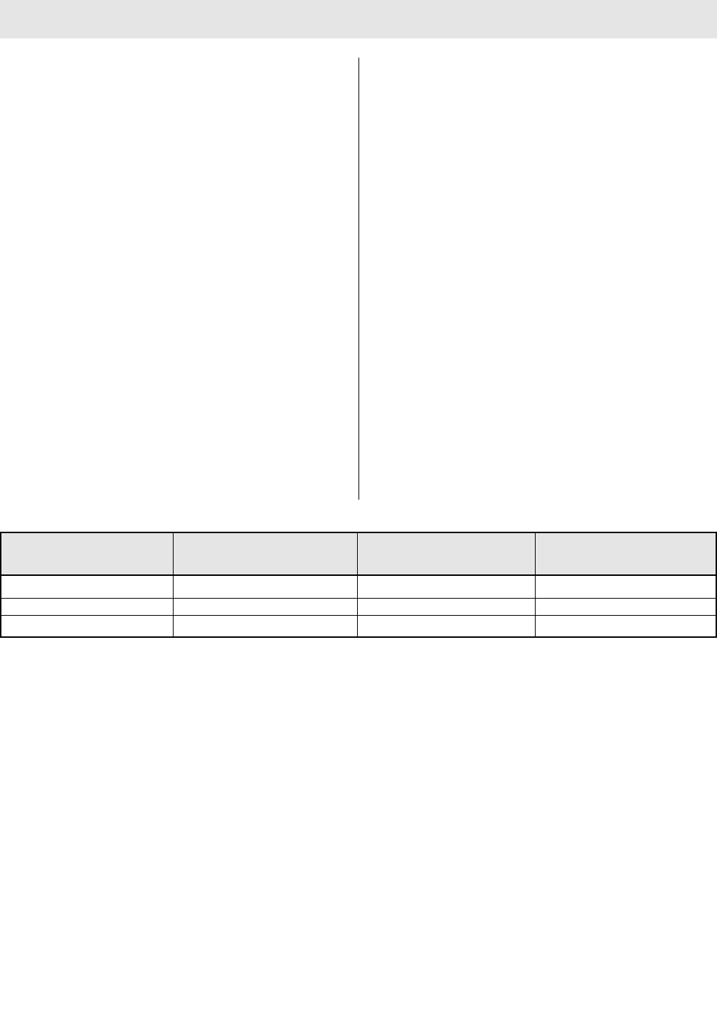
FLOW TEST AND OVERHAUL REQUIREMENTS
FLOW TEST AND OVERHAUL REQUIREMENTS
The Firehawk Regulator and Audi-Larm Alarm must be
flow tested and overhauled at specific time intervals.
These Maintenance Procedures must be performed by a
trained repairperson or at a certified service center.
Contact your MSA sales representative or call the MSA
Customer Service Center at 1-877-MSA-3473. They will
supply the information needed to meet these require-
ments.
Annual flow tests are stated as a requirement in NFPA
1852, Standard on Selection, Care, and Maintenance of
Open-Circuit Self-Contained Breathing Apparatus (SCBA),
2002 Edition, which further emphasizes their importance.
Although this standard relates to SCBA used in the fire
service, MSA requires that a flow test be performed at
least annually on all fire service and non-fire service SCBA
and combination respirators that use a pressure demand
regulator.
The required replacement/overhaul schedule for MSA air
masks is based on apparatus usage on an individual
basis. The frequency required for air mask overhaul
depends upon how often the apparatus is used. MSA air
masks must be overhauled based on the actual level of
usage of the air mask, rather than on time alone.
MSA air masks must be flow tested every year using an
MSA approved flow test device. The following table sum-
marizes MSA’s required frequency for overhaul and flow
testing: An overhaul kit (MSA P/N 10048942) is available.
MSA recommends the routine inspection of all elastomeric
materials including, but not limited to those in the Visual
Inspection and Functional Check section of this manual.
A decision to retire apparatus should be based on an air
mask’s performance data and whether that data meets
the specified level of performance as defined in mainte-
nance requirements from MSA.
*The unit of air mask use is defined as the consumption of
one entire cylinder of air. Example: If three cylinders of air
are used, the air mask would be considered to have been
used three times.
If an assessment of the air mask’s usage cannot be esti-
mated or determined, then the air mask shall be over-
hauled every three years.
37 TAL 016 (L) Rev. 10 - 10082858 - DRAFT 7-21-10
CBRN FireHawk Overhaul Regulators and Audi-Larm
Average Air Mask Usage Frequency Alarm Overhaul Frequency Flow Test Frequency
1 cylinder per day or greater every 1 year every 3 years every year
1 cylinder every other day every 3 years every 8 years every year
1 cylinder per week or less every 10 years every 15 years every year

NOTES
38
TAL 016 (L) Rev. 10 - 10082858 - DRAFT 7-21-10
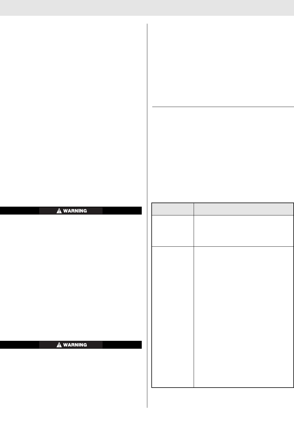
QUICK-FILL SYSTEM
PRECAUTIONS FOR USING QUICK-FILL SYSTEM
1. The Quick-Fill System can only be used to fill
approved air mask cylinders.
2. The Quick-Fill System is not to be used as a "Buddy
Breather" such that two users are sharing the air sup-
plied by one air mask cylinder simultaneously doing so
will void NIOSH approval.
3. The user is responsible for the air supply, which must
meet the requirements of Compressed Gas
Association Specification ANSI/G-7.1, Quality
Verification Level (Grade) D Gaseous Air or better, with
a moisture dew point of not greater than -65°F
(24ppm water vapor, normal). In fire service applica-
tions, MSA recommends breathing air quality in accor-
dance with NFPA 1989. Pressures at the inlet of the
quick-fill hose must not exceed that of the air mask
(2216 psi or 4500 psi).
4. The user also is responsible for connecting the quick-
fill hose to an appropriate secondary air supply.
5. The cylinder must be inspected for damage before
charging.
6. If filling cylinders in fresh air using the Quick-Fill
System, topping off the cylinder is recommended after
the cylinder has cooled from initial fill. Topping off a
cylinder after it has cooled will ensure proper service
time.
• DO NOT use the Quick-Fill System as a "Buddy
Breather" such that two users are sharing the air
supplied by one approved air mask cylinder simul-
taneously; doing so will void NIOSH approval.
• The quick-fill hose assemblies and fittings are
designed to be used with Quality Verification Level
(Grade) D or better air as defined by ANSI/CGA G-
7.1.TRANSFILLING AIR FROM A SECONDARY AIR
SUPPLY. In fire service applications, MSA recom-
mends breathing air quality in accordance with
NFPA 1989.
• DO NOT lubricate the quick-fill fittings.
• DO NOT permit oil, grease, or other contaminants
to come in contact with the quick-fill fittings.
• DO NOT install a Quick-Fill System on a 3000 psi
air mask. This combination will not allow the relief
valve in the 3000 psi URC Assembly to open as
designed.
DO NOT use the Quick-Fill®System, URC Assembly, or
ExtendAire™ System accessories if there is any possi-
bility that the environment contains a CBRN warfare
agent. These air mask accessories are not approved
for use in atmospheres containing CBRN warfare
agents. Failure to follow this warning can result in
serious personal injury or death.
The Quick-Fill System must be used only by qualified,
trained personnel who have carefully read and understood
these instructions, cautions, and warnings. NIOSH
approvals of SCBA from MSA are maintained while trans-
filling air ONLY if appropriate quick-fill hose assemblies
from MSA are used. Quick-fill hose assemblies and fittings
are rated for a maximum working pressure of 4500 psi.
NIOSH approval is maintained only when using the follow-
ing hose assemblies: 485331, 802687, 802688, 802689,
802690, and 48332, for filling cylinders in IDLH atmos-
pheres.
FILLING INSTRUCTIONS FOR QUICK-FILL SYSTEM
A secondary air supply stores compressed breathing air
until needed to refill air mask air cylinders. When transfill-
ing, the secondary air supply pressure must be greater
than air mask cylinder pressure. Examples of air supply
includes: cascade air cylinder refilling systems; high pres-
sure compressor systems with a fixed reservoir or a
portable air system such as the MSA RescueAire™
System.
The following hoses can be used to connect to a sec-
ondary air supply.
39 TAL 016 (L) Rev. 10 - 10082858 - DRAFT 7-21-10
Order MSA P/N Description
485391 Male stainless steel quick-disconnect
with SAE-10 thread, complete with
dust cover (for use as a fitting for
customized refilling systems).
25-FOOT QUICK-FILL HOSES
Note: Female quick-disconnect fittings
include dust covers.
485532 With two female quick-disconnects
487906 With a female quick-disconnect on one
end and a SAE-4 fitting on the other.
487907 With a female quick-disconnect one
end and a CGA-347 (4500 psig) outlet
on the other.
487908 With a female quick-disconnect on one
end and a CGA-346 (2216 psig) outlet
on the other.
487909 With a female quick-disconnect on one
end and a CGA-347 (4500 psig)
coupling nut on the other.
487910 With a female quick-connect on one
end and a CGA-346 (2216 psig)
coupling nut on the other.

QUICK-FILL SYSTEM
1. To connect the quick-fill hose to the secondary air
supply.
a. Turn the air supply on.
If there are leaks from either female fitting, or along
the hose, depressurize the hose and correct the prob-
lem. Such leakage can result in increased fill time.
2. Attach the quick-fill hose to the shoulder mounted
quick-fill fitting.
a. Remove the rubber dust cap from the male quick-fill
fitting. Be sure that the cylinder valve is fully
opened.
b. Remove the rubber dust cap from the female fitting
on the quick-fill hose.
c. Push the female fitting of the hose onto the male
quick-fill fitting until it snaps in place. Pull on the
hose to be sure the connection is secure. Filling
immediately begins when the female fitting fully
engages with the male fitting.
d. After approximately 45-60 seconds, the pressure
between the secondary air supply and the air mask
cylinder will be equal.
Note: If the secondary air supply does not have a suffi-
cient volume of air, the air mask cylinder will not reach
maximum service pressure.
3. Compare the cylinder pressure gauge or FireHawk M7
Control Module (integrated PASS version) reading to
the secondary air supply pressure gauge reading. If
the readings are the same, pressure is equal.
4. To disconnect the quick-fill hose after transfilling, pull
the gray sleeve back. The hose fitting and the male fit-
ting will separate. A hiss or pop may be heard as the
fittings separate and the high pressure air is sealed
off.
5. Immediately install the dust cover on the male fitting.
6. The air mask cylinder is ready for service if the cylin-
der pressure gauge needle is on the corresponding
color band.
TRANSFILLING BETWEEN AIR MASKS
Note: The air mask with the higher pressure reading is the
donor. The air mask with the lower pressure is the receiv-
er. Transfilling between users of air mask should be per-
formed only during life-threatening emergencies or simu-
lated training exercises. Both donor and receiver must
return to fresh air immediately following the procedure.
DO NOT transfill if the donor's audible alarm is ringing
or FireHawk M7 HUD /FireHawk M7 Control Module
are flashing. Failure to follow this warning can result in
shorter escape time to return to fresh air, causing seri-
ous personal injury or death.
The audible alarm begins ringing and heads-up display
system begins flashing to indicate that the pressure in the
cylinder has been reduced to 25% of its rated working
pressure. Remaining service time must be used for
escape to fresh air. If the donor's audible alarm begins
ringing or FireHawk M7 HUD/FireHawk M7 Control
Module (integrated PASS version) begins flashing during
transfilling, the donor should disconnect and preserve his
escape time.
1. If the donor's alarm is not ringing and FireHawk M7
HUD/FireHawk M7 Control Module (integrated PASS
version) are not flashing and you have sufficient air to
transfill to a receiver, (greater than 1000 psi for 2216 psi
air masks and greater than 2000 psi for 4500 psi air
masks), follow these steps.
a. Remove the 3 foot emergency transfill hose from its
protective pouch.
b. Remove the rubber dust cover from both female fit-
tings on the quick-fill hose assembly.
c. Remove the rubber dust cover from the male Quick-
Fill System fitting.
d. Push the female fittings on to the male fittings until
they click in place. Pull on the hose to be sure it
snapped in place.
If serious leakage is noticed from either of the two
female fittings, or anywhere along the hose, discon-
nect the female fittings and return to fresh air immedi-
ately. Failure to follow this warning can result in seri-
ous personal injury or death.
e. After approximately 45-60 seconds, pressure
between the air mask cylinders will be equal.
f. Disconnect the quick-fill hose from the air mask by
pulling the gray sleeve back on both ends. A hiss or
pop may be heard as the fittings separate and the
high pressure air is sealed off.
g. Immediately install the dust cover on the quick-fill
male fitting. The dust cover prevents dirt, water, and
debris from entering the fitting, and acts as a redun-
dant seal.
QUICK-FILL FITTING LEAKAGE
1. When transfilling in fresh air and the dust cover will
not stay on the male fitting because air is leaking, cor-
rect the condition before using the air mask.
2. When transfilling in a contaminated atmosphere and
the dust cover will not stay on the male fitting because
air is leaking:
a. Immediately reconnect the quick-fill hose to seal off
the leak and return to fresh air.
40
TAL 016 (L) Rev. 10 - 10082858 - DRAFT 7-21-10

QUICK-FILL SYSTEM
b. If the hose will not reconnect, reach behind and
close the cylinder valve. Air pressure in the regulator
will drop, and the leak will slow down.
c. Quickly replace the protective dust cap on the male
fitting. This will form a redundant seal.
d. Open the cylinder valve and return to fresh air
immediately. The dust cover prevents dirt, water,
and debris from entering the fitting, and acts as a
redundant seal.
QUICK-FILL SYSTEM HOSE STORAGE
1. Preparing the Quick-Fill System hose for storage:
a. Press in on the center of the quick-disconnect dust
cap to release any pressure in the quick-fill hose.
b. Roll up the hose and place it in its protective pouch.
41 TAL 016 (L) Rev. 10 - 10082858 - DRAFT 7-21-10

NOTES
42
TAL 016 (L) Rev. 10 - 10082858 - DRAFT 7-21-10
EXTENDAIRE SYSTEMS
INSTRUCTIONS FOR USE
GENERAL INFORMATION
Two air masks equipped with an ExtendAire System can
share a common air supply during emergency escape.
When connecting two ExtendAire Systems, two
ExtendAire II Systems or one ExtendAire System and one
ExtendAire II System, both users will receive intermediate
pressure air from the donor's first stage regulator and
cylinder. The duration of the remaining air supply will be
reduced by at least half.
The SCBA is approved by NIOSH without inter-connecting
two users to one apparatus. NIOSH does not certify
“buddy breathers”. Therefore, the attachment of the
receiver's regulator to the donor's apparatus voids the
NIOSH approval for both air masks.
Air Hose: When used as a combination apparatus, the
device shall be supplied with respirable air through air
supply hose with a minimum length of 8 feet and maxi-
mum length of 300 feet within the pressure range of 85-90
psi. A maximum of 12 sections of straight or uncoiled air
supply hose may be used in making up the working
length of hose. When using coiled hose, a maximum of
six sections may be used and each section is considered
to be 50 feet long. Hose sections vary from 8 feet to 100
feet lengths. The air-line connection to the apparatus is to
be made through approved quick-disconnects only. The
purity of the air supply is the responsibility of the user. The
respirator is approved only when the air supplied meets
the requirements of the Compressed Gas Association
Specification G-7. 1989 quality verification level (Grade) D
for Gaseous Air.
Use this emergency escape breathing system for life
threatening emergencies and simulated training exer-
cises only. All other adequate means of escape must
be considered before using this device.
• During use the air supply, and consequently the
service time, is reduced approximately in half.
Before connecting two users make sure the air
supply is sufficient for both users to escape; other-
wise do not use the system.
• DO NOT use the system if the donor's audible
alarm is ringing.
• The NIOSH Approval for both apparatus are void
when this device is used, due to the difficulty in
maneuvering during escape. Exercise extreme care
while connected together. Mobility and range of
motion will be limited when donor's and receiver's
air masks are connected.
• Maintain slack in the air lines during maneuvering
and while connected together. DO NOT pull on the
hoses.
If the above measures cannot be followed or to pro-
vide greater escape protection, use the Quick-Fill
System. It maintains approval while transfilling and
does not exhibit the above hazards.
DO NOT use the Quick-Fill®System, URC Assembly, or
ExtendAire System accessories if there is any possibil-
ity that the environment contains a CBRN warfare
agent. These air mask accessories are not approved
for use in atmospheres containing CBRN warfare
agents. Failure to follow this warning can result in
serious personal injury or death.
EMERGENCY ESCAPE BREATHING SYSTEM:
INSTRUCTIONS FOR USE
The ExtendAire Systems use Snap-Tite quick-discon-
nects.
The Snap-Tite quick-disconnect has two significant fea-
tures.
1. It is single action to connect. The coupler is pushed
firmly over the plug to engage.
2. It is a locking type that requires two actions to discon-
nect.
a. Push the two sides of the quick-disconnect towards
each other. (The plug should advance into the cou-
pler end approximately 1/8".)
b. Slide the coupler’s outer sleeve away from the plug.
Pull the plug out of the coupler. Ensure that unused
guick-disconnect plugs and couples are protected
by dust caps.
DO NOT install or attempt to use any hose assembly
or fitting other than those supplied by MSA for the
ExtendAire System. Failure to follow this warning can
result in serious personal injury or death.
PREPARATION FOR USE
BEFORE ENTERING A TOXIC ATMOSPHERE
1. Don the apparatus as described in the donning sec-
tion.
a. ExtendAire System - Ensure proper engagement of
the Snap-Tite quick-disconnect coupling on the
intermediate pressure hose (at the manifold tee).
b. ExtendAire II System - Ensure Manifold and hose
are fully contained in the ExtendAire II System
pouch and that the snaps are fastened.
43 TAL 016 (L) Rev. 10 - 10082858 - DRAFT 7-21-10

EXTENDAIRE SYSTEMS
PROVIDING OR OBTAINING EMERGENCY BREATHING
SUPPORT
Follow these procedures to connect and disconnect
the emergency escape breathing system hardware.
Individual development of operating procedures and
sufficient training is required to use this equipment in
actual emergency conditions. Failure to follow this
warning can result in serious personal injury or death.
ExtendAire System Hose Connection Procedure
1. Remove the dust cap from the quick-disconnect on
the donor's intermediate pressure manifold block.
2. Disconnect the receiver's second stage regulator hose
from their intermediate pressure manifold block by
disengaging the Snap-Tite quick-disconnect fitting.
Perform the following disconnect and connect steps
quickly. The receiver will not have a supply of breath-
able air while the receiver’s second stage regulator
hose is disconnected. Failure to follow this warning
can result in serious personal injury or death.
3. Connect the receiver's second stage regulator hose to
the donor's manifold block.
a. Push the coupler of the receiver's hose firmly over
the plug on the donor's manifold.
b. Check that the hose is properly routed and not tan-
gled with any other part of the apparatus (i.e. neck
strap, chest strap, etc.)
c. Check for full engagement by pulling at the quick-
disconnect to assure that the socket does not sepa-
rate from the plug. The apparatus of the donor will
supply air for emergency escape of the two individ-
uals. The duration of the remaining air supply will (at
least) be reduced in half.
ExtendAire System Hose Disconnection Procedure
1. Upon reaching a safe, non-toxic atmosphere, a stag-
ing area or performing other emergency egress proce-
dures, uncouple the receiver's hose at the quick-dis-
connect.
2. Replace the dust cap on the Snap-Tite plug.
ExtendAire II System Connection Procedure
1. Pull on the pouch opening of both the donor's and
receiver's pouches.
2. Fully remove the manifold and hose from each pouch.
3. Remove the dust caps from both manifolds.
4. Connect the receiver's manifold to the donor's mani-
fold.
a. Push the coupler on the receiver's manifold firmly over
the plug on the donor's manifold.
b. Check that the hoses are properly routed, not kinked,
and not tangled with any other part of the apparatus
(i.e. second stage regulator hose, neck strap, chest
strap, etc.)
c. Check for full engagement by pulling at the quick-dis-
connect and assure that the coupler does not sepa-
rate from the plug. The apparatus of the donor will
supply air for emergency escape of the two individu-
als. The duration of the remaining air supply will (at
least) be reduced in half.
ExtendAire II System Disconnection Procedure
1. Upon reaching a safe, non-toxic atmosphere, a stag-
ing area or performing emergency egress procedures,
uncouple the receiver's manifold at the quick-discon-
nect.
2. Replace the dust caps on the quick-disconnects.
3. Coil the hose neatly, insert into the pouch, and close
the pouch by fastening the snaps.
The receiver's facepiece or regulator must be
removed upon disconnection from the donor's air sup-
ply. Failure to follow this warning can result in serious
personal injury or death from suffocation.
44
TAL 016 (L) Rev. 10 - 10082858 - DRAFT 7-21-10

FIREHAWK M7 TELEMETRY MODULE
FIREHAWK M7 TELEMETRY MODULE (INTEGRATED
PASS VERSION)
The FireHawk M7 Telemetry Module is designed to allow
the air mask to communicate with a remote base station
while in use. The FireHawk M7 Air Mask with FireHawk
M7 Telemetry Module installed will transmit vital statistics
such as cylinder pressure, temperature alarm (if thermal
alarm is enabled), service time remaining, and PASS alarm
to the base station. The base station also has the ability
to send an evacuation command to the air mask. The
FireHawk M7 Telemetry Module uses a special version of
the FireHawk M7 Control Module and FireHawk M7 Power
Module.
All basic functions of the air mask are the same as those
described in the During Use section of this manual except
for the following differences:
•Turning the FireHawk M7 Control Module On: When
the FireHawk M7 Control Module is activated in the
presence of a remote base station, the air mask auto-
matically begins to log on to that base station. When
the air mask is successfully logged on to the base sta-
tion, a radio link indicator will appear on the display of
the FireHawk M7 Control Module.
•Evacuation Signal: The air mask has the ability to
receive an evacuation signal from the remote base
station after it has been successfully logged on to the
base station. When an evacuation signal has been
sent by the base station, the “running man” icon will
appear, and flash, on the display of the FireHawk M7
Control Module and a unique audible alarm will be
emitted from the FireHawk M7 Power Module. The
evacuation signal must be manually confirmed by the
user by pressing the reset button (yellow) twice within
approximately one second. This confirms the evacua-
tion signal by sending a confirmation signal back to
the base station. Once the evacuation signal has
been manually confirmed by the user, the “running
man” icon will stop flashing and remain on the display
until the FireHawk M7 Control Module has been
turned off.
•PASS Alarm: The PASS alarm will sound and function
normally with the FireHawk M7 Telemetry Module.
When the air mask emits a full PASS alarm, a signal is
automatically sent to the base station to alert Incident
Command.
•Thermal Alarm: When the air mask is exposed to
temperature conditions that warrant a thermal alarm, a
signal is automatically sent to the base station to alert
Incident Command.
•Low Battery: When the FireHawk M7 Power Module
reaches a low battery condition, a signal is automati-
cally sent to the base station to alert Incident
Command. A signal is not sent to the base station if
the FireHawk M7 HUD has a low battery condition.
•Data Log: The data logging feature of the FireHawk
M7 Control Module logs the status of the radio link to
the base station as well as any evacuation signals that
the air mask has received.
•Radio Link Indicator: The FireHawk M7 Control
Module has a radio link indicator located in the upper
left portion of the display. When this icon is displayed,
the air mask is logged on to a base station and within
range. When the radio link indictor is not shown, the
FireHawk M7 Control Module has not been logged on
to a base station or is out of the range of the base
station.
•Turning the FireHawk M7 Control Module Off: To
turn the FireHawk M7 Control Module off, press the
reset button (yellow) twice within approximately one
second. If the air mask is logged on to the base sta-
tion, there will be a delay between the two presses of
the reset button and the actual shutdown of the
device. Before the FireHawk M7 Control Module com-
pletely turns off, the base station must remove the air
mask from its registry. This causes the slight delay
between pressing the reset button and the actual
shutdown of the device.
ID Tag (PN 10083875), for use with FireHawk M7
Telemetry Module
When the FireHawk M7 Telemetry Module is used with the
FireHawk M7 Air Mask, an ID Tag is used to assign a fire-
fighter’s name to the air mask. The name assigned to the
air mask will be displayed for that air mask on the MSA
Accountabiity System Software. The name ID Tag must be
scanned into the FireHawk M7 Control Module at the start
of each shift (every 24 hours by default).
Note: The FireHawk M7 Interface Software can be used
to change this default to allow a name ID to be perma-
nently assigned to the air mask until a new name ID Tag
has been scanned.
A team ID Tag can also be used to assign a team/truck
and position to the air mask. If a team ID Tag has been
scanned into the FireHawk M7 Control Module but a
name ID Tag has not been scanned, the team ID will be
displayed on the SCBA monitoring software to provide
accountability even if the firefighter forgot to scan the
name ID Tag. Once a team ID Tag has been scanned into
the FireHawk M7 Control Module, the team ID will remain
with the air mask until another team ID Tag has been
scanned. If a team ID or name ID has not been assigned
to the air mask, the FireHawk M7 Control Module serial
number will be displayed as the firefighter’s ID when
logged onto the base station.
A base station ID can be used to assign a specific base
station ID to an air mask. When more than one base sta-
tion is present and actively monitoring at an incident, an
air mask with an assigned base station will search for the
preferred base station first to log on to, and if it does not
find the assigned base station within 20 seconds, it will
search for the first available base station and log on to it.
45 TAL 016 (L) Rev. 10 - 10082858 - DRAFT 7-21-10
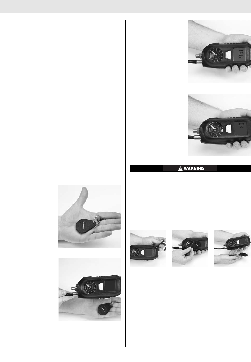
FIREHAWK M7 TELEMETRY MODULE
If a base station ID has not been assigned to the air mask,
it will log on to the first base station that it finds once the
unit has been turned on. Once a base station ID tag has
been scanned into the FireHawk M7 Control Module, this
base station ID will remain with the air mask until another
base station ID tag has been scanned.
The ID Tag has a space for the user to place a label in
which the ID information can be written on the outside of
the ID Tag for easy identification.
Before using the ID tag, inspect for damage or cracks in
the case. If damage is found, discard and replace the ID
tag.
Scanning the ID Tag into the FireHawk M7 Control
Module
1. Prior to pressurization of the air mask and during
inspection, the user can “tag in” to the air mask. The
most recent ID Tag data that is stored inthe FireHawk
M7 Control Module will be used as the identification
for the air mask on the MSA Accountability System
Software. If no ID Tag data has been assigned to the
air mask, the FireHawk M7 Control Module serial num-
ber will be used as its identification on the base sta-
tion PC screen.
Note: The air mask must not be pressurized and
FireHawk M7 Control Module must be turned off to scan
the ID Tag.
2. Take the ID Tag and
place the attachment
clip between your fin-
gers on your left hand.
The ID Tag should lie in
your palm.
3. Move the FireHawk M7
Control Module over
top of the ID Tag.
4. Press and hold the
green mode button with
the thumb for 2 second
for the word “TAG” to
disply.
5. At that point, the word
will change to “OK”
within a few seconds
confirming the tagging
process is complete.
DO NOT use the tag to preess the mode button, place
it on top of the FireHawk M7 Control Module, or next
to the FireHawk M7 Control Module. The tagging
instructionsmust be followed to have the ID Tag within
range of the short range radio to complete the tagging
process. If the tag is not, the PASS device can lockup
showing the word “TAG” or “DATA” and cannot be
shutoff. To fix the lockkup, the batteries must be
removed for 10 seconds and then reinstalled.
6. The word “TAG” will display for 10 seconds if the
mode button is not pressed again. If the mode button
is pressed again after the word “TAG” appears, then
the PASS will enter data mode showing the word
“DATA”. To get back into tag mode, press themode
button again to enter sleep mode and repeat the pre-
vious steps.
Note: The “data” mode is used to change the device set-
tings or read the data log while using the FireHawk M7
Interface Software.
46
TAL 016 (L) Rev. 10 - 10082858 - DRAFT 7-21-10

FIREHAWK M7 TELEMETRY MODULE
Using the Base Station with the FireHawk M7
Telemetry Module
The FireHawk M7 Telemetry Module is designed to work
in conjunction with a remote base station unit. This base
station unit must be connected to a personal computer or
laptop before use. Refer to the MSA Accountability
System Software instructions (PN 10068929) for more
information.
Follow the PC or notebook computer manufacturer’s
recommendations for exposure to environmental con-
ditions to prevent damage to the system. Failure to do
so may cause system failure and the loss of monitor-
ing capability on the PC or notebook computer.
Using the M7 Firehawk Air Mask with FireHawk M7
Telemetry Module
Logging the Air Mask on to the Base Station
1. Turn on the FireHawk M7 Control Module on by open-
ing the cylinder valve or by pressing and holding the
alarm button.
2. A helmet icon representing the user of the air mask
will appear on the base station PC screen.
3. When the base station has established contact with the
air mask and all initial information has been obtained,
the radio link indicator will appear in the upper left cor-
ner of the FireHawk M7 Control Module display.
4. Periodically check the status of the radio link indicator
on the display of the FireHawk M7 Control Module. If
the signal strength indicator begins to flash, this
means that the air mask is out of range from the base
station. The signal strength indicator will stop flashing
when the air mask returns within range of the base
station.
If the signal strength indicator does not appear on the
FireHawk M7 Control Module display, the base station
has not logged the unit on and can not monitor the
status of that firefighter.
Logging the Air Mask off of the Base Station
1. Once the user has returned to fresh air the FireHawk
M7 Control Module may be turned off.
2. Close the cylinder valve and purge the remaining air
from the system using the Firehawk Regulator bypass.
When the pressure falls below 200 psi, turn the
FireHawk M7 Control Module off (sleep mode) by
pressing the reset button twice in approximately one
second. (When the air mask is logged on to a base
station, there may be a delay between the two rapid
presses of the reset button and the actual shutdown
of the FireHawk M7 Control Module. Before the
FireHawk M7 Control Module completely turns off, the
base station must log off the air mask and send out a
final confirmation signal.
Evacuation Signal
If the air mask is logged on to the base station, the inci-
dent command will have the ability to send an evacuation
signal to the air mask. When an evacuation signal is sent
to the air mask, the FireHawk M7 Power Module will begin
to beep repeatedly and a flashing “running man” icon will
appear on the FireHawk M7 Control Module display. The
evacuation alarm will continue to sound until the reset
button on the FireHawk M7 Control Module has been
pressed twice within approximately one second. This con-
firms the evacuation by sending a confirmation signal
back to the base station.
47 TAL 016 (L) Rev. 10 - 10082858 - DRAFT 7-21-10
48
TAL 016 (L) Rev. 10 - 10082858 - DRAFT 7-21-10
Mine Safety Appliances Company
Lifetime Warranty
and Terms of Sale
1. Express Warranty—Air Masks and/or components furnished under
this order carry a Lifetime Warranty against material defects and/or
faulty workmanship, with the exception of those components
specifically identified herein. MSA shall be released from all
obligations under this warranty in the event repairs or modifications
are made by persons other than its own or authorized service
personnel or if the warranty claim results from abuse, misuse, or
normal wear and tear of the product. No agent, employee or
representative of MSA may bind MSA to any affirmation,
2. Exceptions—The products below are excluded from MSA’s Lifetime Warranty:
3. Exclusive Remedy—It is expressly agreed that the Purchaser’s sole and
exclusive remedy for breach of the above warranty, for any tortious
conduct of MSA, or for any other cause of action, shall be the repair
and/or replacement, at MSA’s option, of any equipment or parts thereof,
that after examination by MSA are proven to be defective. Replacement
equipment and/or parts will be provided at no cost to the Purchaser,
F.O.B. Purchaser’s named place of destination. Failure of MSA to
successfully repair any nonconforming product shall not cause the
remedy established hereby to fail of its essential purpose.
Product Description Warranty Period Routine S.A.R. Maintenance
Air Mask (less Cylinder) Lifetime
Air Mask Cylinder Until end of service life
as controlled by
gov’t. reg/DOT
Air Mask Replacement Parts Lifetime
Air Mask Critical Repair Parts Lifetime
MSA requires that the air mask be maintained as
specified in the Operations and Instructions Manual;
however, the warranty coverage is for material defects
and/or faulty workmanship only, and is not dependent on
performing routine maintenance. The material and labor
costs of overhaul procedures and other routine main-
tenance are the responsibility of the purchaser and are
not covered by the warranty.
representation or modification of the warranty concerning the
goods sold under this contract. MSA makes no warranty concerning
components or accessories not manufactured by MSA, but will
pass on to the Purchaser all warranties of manufacturers of such
components.
THIS WARRANTY IS IN LIEU OF ALL OTHER
WARRANTEES, EXPRESS, IMPLIED OR STATUTORY, AND IS
STRICTLY LIMITED TO THE TERMS HEREOF: MSA SPECIFICALLY
DISCLAIMS ANY WARRANTY OF MERCHANTABILITY OR OF
FITNESS FOR A PARTICULAR PURPOSE.
4. Exclusion of Consequential Damages—Purchaser specifically
understands and agrees that under no circumstances will
MSA be liable to Purchaser for economic, special, incidental,
or consequential damages or losses of any kind whatsoever,
including but not limited to, loss of anticipated profits and any other
loss caused by reason of the non-operation of the goods. This
exclusion is applicable to claims for breach of warranty,
tortious conduct or any other cause of action against MSA.
ID 0170-10-MC/ Nov 2007
© MSA 2007 Printed in U.S.A.
Corporate Headquarters
P.O. Box 426
Pittsburgh, PA 15230 USA
Phone (412) 967-3000
www.MSAFire.com
U.S. Customer Service Center
1-800-MSA-2222
MSA International
Phone (412) 967-3354
FAX (412) 967-3451
Fire Service Customer Service:
Phone 1-877-MSA-FIRE
Fax 1-800-967-0398
MSA Canada
Phone 800-267-0672
Fax 905-238-4151
MSA Mexico
Phone 52 (2) 1 22 57 30
Fax 52 (5) 3 59 43 30
Product Description Exception Warranty Period
Facemask Blank, Hoses
& Nose Cup Rubber Product 5 Year Limited/Age Deterioration
Clear Command Communications MSA Limited Warranty 1 Year
FireHawk M7 Air Mask Electronics - Control Module
HUD, Power Module, Communications Modul
NightFighter HUD Transmitter
eMSA Limited Warranty 3 1
/
2Years
Non-Rechargeable Batteries Expendable and/or Consumable Parts N/A