MTD 13A2775S000 User Manual TRACTOR Manuals And Guides 1311209L
User Manual: MTD 13A2775S000 13A2775S000 MTD TRACTOR - Manuals and Guides View the owners manual for your MTD TRACTOR #13A2775S000. Home:Lawn & Garden Parts:MTD Parts:MTD TRACTOR Manual
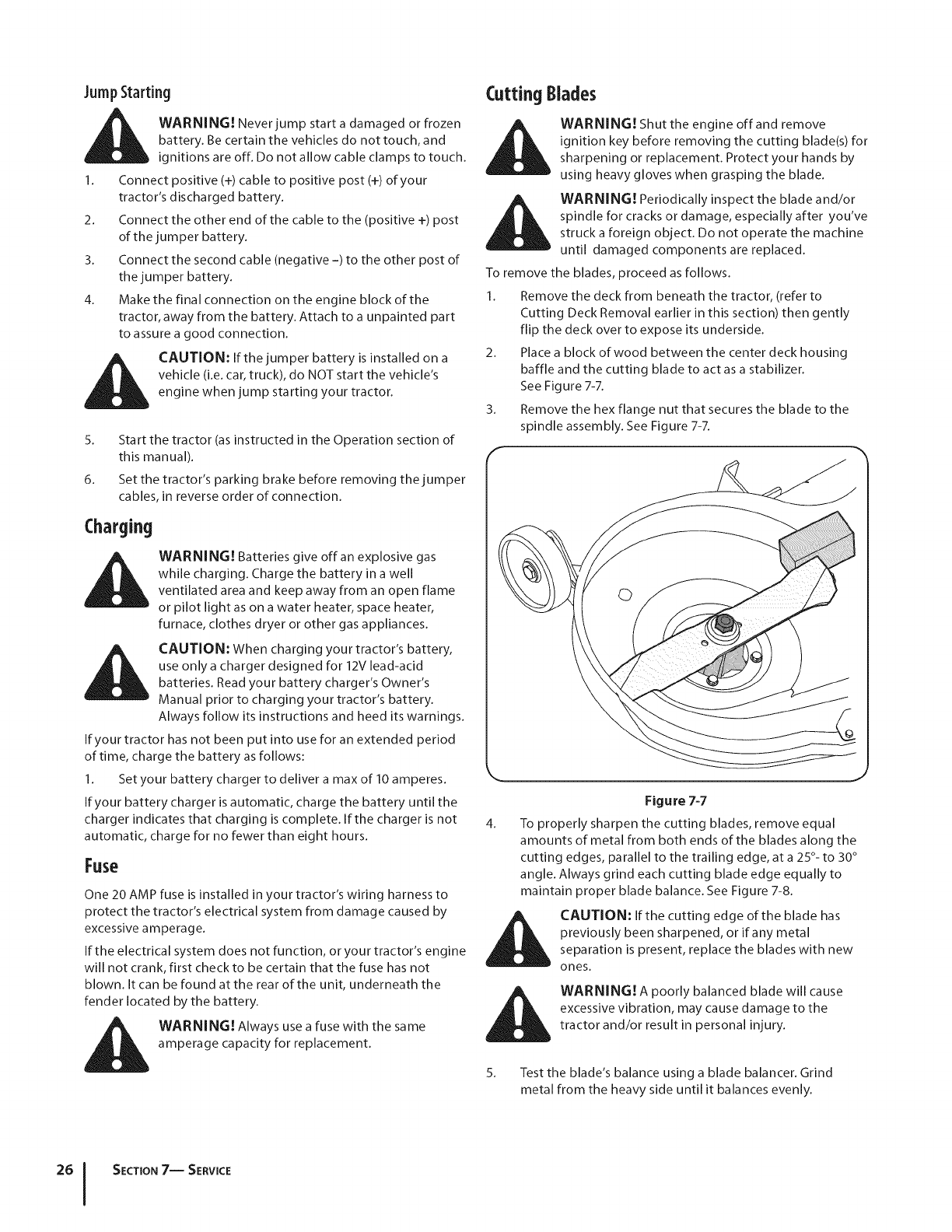
Open the PDF directly: View PDF ![]() .
.
Page Count: 68

Safe Operation Practices • Set-Up • Operation • Maintenance • Service • Troubleshooting • Warranty
OPER roR's L
Model Series 760-770 Lawn Tractor
MTD LLC, P.O. BOX 361131 CLEVELAND, OHiO 44136-0019
PrintedIn USA FormNo.769-08412
(November1,2012)
ToTheOwner 1
ThankYou
Thank you for purchasing a lawn tractor manufactured by MTD.
It was carefully engineered to provide excellent performance
when properly operated and maintained.
Please read this entire manual prior to operating the equipment.
It instructs you how to safely and easily set up, operate and
maintain your machine. Please be sure that you, and any other
persons who will operate the machine, carefully follow the
recommended safety practices at all times. Failure to do so could
result in personal injury or property damage.
All information in this manual is relative to the most recent
product information available at the time of printing. Review
this manual frequently to familiarize yourself with the machine,
its features and operation. Please be aware that this Operator's
Manual may cover a range of product specifications for various
models. Characteristics and features discussed and/or illustrated
in this manual may not be applicable to all models. MTD
reserves the right to change product specifications, designs and
equipment without notice and without incurring obligation.
If applicable, the power testing information used to establish
the power rating of the engine equipped on this machine can be
found at www.opei.org or the engine manufacturer's web site.
If you have any problems or questions concerning the machine,
phone your local authorized MTD service dealer or contact us
directly. MTD's Customer Support telephone numbers, website
address and mailing address can be found on this page. We want
to ensure your complete satisfaction at all times.
Throughout this manual, all references to fightand left side of the
machine are observed from the operating position
The engine manufacturer is responsible for all engine-related
issues with regards to performance, power-rating, specifications,
warranty and service. Please refer to the engine manufacturer's
Owner's/Operator's Manual, packed separately with your
machine, for more information.
Table of Contents
Safe Operation Practices ........................................ 3
Assembly &Set-Up .................................................. 9
Controls & Features ................................................ 13
Operation ................................................................ 16
Maintenance &Adjustment ................................ 20
Service .................................................................... 24
Troubleshooting .................................................... 29
Replacement Parts ................................................ 30
Attachments &Accessories ................................... 31
Emission Control Statement ................................. 33
Warranty ................................................................ 35
Spanish ................................................................... 36
RecordProduct information
Before setting up and operating your new equipment, please
locate the model plate on the equipment and record the
information in the provided area to the right. You can locate the
model plate by looking beneath the seat. This information will
be necessary, should you seek technical support via our web site,
Customer Support Department, or with a local authorized service
dealer.
MODEL NUMBER
NNNNNNNNNND
SERIALNUMBER
DIqFllqFllqFllqNIqD
CustomerSupport
Please do NOT retum the machine to the retailer or dealer without first contacting our Customer Support Department.
If you have difficulty assembling this product or have any questions regarding the controls, operation, or maintenance of
this machine, you can seek help from the experts. Choose from the options below:
0 Visit us on the web at www.mtdproducts.com
0
0
I
See How-to Maintenance and Parts Installation Videos at www.mtdparts,com/KnowledgeCenter
Call a Customer Support Representative at (800) 800-7310 or (330) 220-4683
Write us at MTD LLC •RO. Box 361131 •Cleveland, OH •44136-0019
ImportantSafeOperationPractices 2
WARNING! This symbol points out important safety instructions which, if not followed,
could endanger the personal safety and/or property of yourself and others. Read and follow
all instructions in this manual before attempting to operate this machine. Failure to comply
with these instructions may result in personal injury.
When you see this symbol. NEED ITS WARNING!
CALIFORNIA PROPOSITION 65
_ARNING! Engine Exhaust, some of its constituents, and certain vehicle components
contain or emit chemicals known to State of California to cause cancer and birth defects
or other reproductive harm.
_ARNING! Battery posts, terminals, and related accessories contain lead and lead
compounds, chemicals known to the State of California to cause cancer and reproductive
harm. Wash hands after handling
DANGER! This machine was built to be operated according to the safe operation practices in
this manual. As with any type of power equipment, carelessness or error on the part of the
operator can result in serious injury. This machine is capable of amputating hands and feet
and throwing objects. Failure to observe the following safety instructions could result in
serious injury or death.
GeneralOperation
1. Read, understand, and follow all instructions on the
machine and in the manual(s) before attempting to
assemble and operate. Keep this manual in a safe place for
future and regular reference and for ordering replacement
parts.
2. Be familiar with all controls and their proper operation.
Know how to stop the machine and disengage them
quickly.
3. Never allow children under 14 years of age to operate this
machine. Children 14 and over should read and understand
the instructions and safe operation practices in this manual
and on the machine and should be trained and supervised
by an adult.
4. Never allow adults to operate this machine without proper
instruction.
5. To help avoid blade contact or a thrown object injury,
keep bystanders, helpers, children and pets at least 75 feet
from the machine while it is in operation. Stop machine if
anyone enters the area.
6. Thoroughly inspect the area where the equipment is to be
used. Remove all stones, sticks, wire, bones, toys, and other
foreign objects which could be picked up and thrown by
the blade(s). Thrown objects can cause serious personal
injury.
7. Plan your mowing pattern to avoid discharge of material
toward roads, sidewalks, bystanders and the like. Also,
avoid discharging material against a wall or obstruction
which may cause discharged material to ricochet back
toward the operator.
8. Always wear safety glasses or safety goggles during
operation and while performing an adjustment or repair
to protect your eyes. Thrown objects which ricochet can
cause serious injury to the eyes.
9. Wear sturdy, rough-soled work shoes and close-fitting
slacks and shirts. Loose fitting clothes and jewelry can be
caught in movable parts. Never operate this machine in
bare feet or sandals.
10. Be aware of the mower and attachment discharge direction
and do not point it at anyone. Do not operate the mower
without the discharge cover or entire grass catcher in its
proper place.
11. Do not put hands or feet near rotating parts or under the
cutting deck. Contact with the blade(s) can amputate
hands and feet.
23.
24.
12. Amissingordamageddischargecovercancauseblade
contactorthrownobjectinjuries.
13. Stoptheblade(s)whencrossinggraveldrives,walks,or
roadsandwhilenotcuttinggrass.
14. Watchfortrafficwhenoperatingnearorcrossing
roadways.Thismachineisnotintendedforuseonany
publicroadway.
15. Donotoperatethemachinewhileundertheinfluenceof
alcoholordrugs.
16. Mowonlyindaylightorgoodartificiallight.
17. Nevercarrypassengers.
18. Disengageblade(s)beforeshiftingintoreverse.Backup
slowly.Alwayslookdownandbehindbeforeandwhile
backingtoavoidaback-overaccident.
19. Slowdownbeforeturning.Operatethemachinesmoothly.
Avoiderraticoperationandexcessivespeed.
20. Disengageblade(s),setparkingbrake,stopengineandwait
untiltheblade(s)cometoacompletestopbeforeremoving
grasscatcher,emptyinggrass,uncloggingchute,removing
anygrassordebris,ormakinganyadjustments.
21. Neverleavearunningmachineunattended.Alwaysturn
offblade(s),placetransmissioninneutral,setparking
brake,stopengineandremovekeybeforedismounting.
22. Useextracarewhenloadingorunloadingthemachineinto
atrailerortruck.Thismachineshouldnotbedrivenupor
downramp(s),becausethemachinecouldtipover,causing
seriouspersonalinjury.Themachinemustbepushed
manuallyonramp(s)toloadorunloadproperly.
Mufflerandenginebecomehotandcancauseaburn.Do
nottouch.
25.
26.
Checkoverheadclearancescarefullybeforedrivingunder
lowhangingtreebranches,wires,dooropeningsetc.,
wheretheoperatormaybestruckorpulledfromthe
machine,whichcouldresultinseriousinjury.
Disengageallattachmentclutches,depressthebrake
pedalcompletelyandshiftintoneutralbeforeattempting
tostartengine.
Yourmachineisdesignedtocutnormalresidentialgrassof
aheightnomorethan10".Donotattempttomowthrough
unusuallytall,drygrass(e.g.,pasture)orpilesofdryleaves.
Drygrassorleavesmaycontacttheengineexhaustand/
orbuilduponthemowerdeckpresentingapotentialfire
hazard.
27. Useonlyaccessoriesandattachmentsapprovedforthis
machinebythemachinemanufacturer.Read,understand
andfollowallinstructionsprovidedwiththeapproved
accessoryorattachment.
28. Dataindicatesthatoperators,age60yearsandabove,are
involvedinalargepercentageofridingmower-related
injuries.Theseoperatorsshouldevaluatetheirability
tooperatetheridingmowersafelyenoughtoprotect
themselvesandothersfromseriousinjury.
29. Ifsituationsoccurwhicharenotcoveredinthismanual,use
careandgoodjudgment.Contactyourcustomerservice
representativeforassistance.
SlopeOperation
Slopes are a major factor related to loss of control and tip-over
accidents which can result in severe injury or death. All slopes
require extra caution. If you cannot back up the slope or if you
feel uneasy on it, do not mow it.
For your safety, use the slope gauge included as part of this
manual to measure slopes before operating this machine on
a sloped or hilly area. If the slope is greater than 15 degrees as
shown on the slope gauge, do not operate this machine on that
area or serious injury could result.
Do:
1. Mow up and down slopes, not across. Exercise extreme
caution when changing direction on slopes.
2. Watch for holes, ruts, bumps, rocks, or other hidden
objects. Uneven terrain could overturn the machine. Tall
grass can hide obstacles.
3. Use slow speed. Choose a low enough speed setting so
that you will not have to stop or shift while on the slope.
Tires may lose traction on slopes even though the brakes
are functioning properly. Always keep machine in gear
when going down slopes to take advantage of engine
braking action.
4. Follow the manufacturer's recommendations for wheel
weights or counterweights to improve stability.
5. Use extra care with grass catchers or other attachments.
These can change the stability of the machine.
6. Keep all movement on the slopes slow and gradual. Do
not make sudden changes in speed or direction. Rapid
engagement or braking could cause the front of the
machine to lift and rapidly flip over backwards which could
cause serious injury.
7. Avoid starting or stopping on a slope. If tires lose traction,
disengage the blade(s) and proceed slowly straight down
the slope.
Do Not:
1. Do not turn on slopes unless necessary; then, turn slowly
and gradually downhill, if possible.
2. Do not mow near drop-offs, ditches or embankments. The
mower could suddenly turn over if a wheel is over the edge
of a cliff, ditch, or if an edge caves in.
3. Do not try to stabilize the machine by putting your foot on
the ground.
4. Do not use a grass catcher on steep slopes.
5. Do not mow on wet grass.Reduced traction could cause
sliding.
6. Do not shift to neutral and coast downhill. Over-speeding
may cause the operator to lose control of the machine
resulting in serious injury or death.
7. Do not tow heavy pull behind attachments (e.g. loaded
dump cart, lawn roller, etc.) on slopes greater than 5
degrees. When going down hill, the extra weight tends
to push the tractor and may cause you to loose control
(e.g.tractor may speed up, braking and steering ability are
reduced, attachment may jack-knife and cause tractor to
overturn).
4, I SECTION2 -- IMPORTANT SAFE OPERATION PRACTICES
Children
1. Tragic accidents ca n occur if the operator is not alert to the
presence of children. Children are often attracted to the
machine and the mowing activity. They do not understand
the dangers. Never assume that children will remain where
you last saw them.
a. Keep children out of the mowing area and in
watchful care of a responsible adult other than the
operator.
b. Be alert and turn machine off if a child enters the
area.
c. Before and while backing, look behind and down for
small children.
d. Never carry children, even with the blade(s) shut off.
They may fall offand be seriously injured or interfere
with safe machine operation.
e. Use extreme care when approaching blind corners,
doorways, shrubs, trees or other objects that may
blockyour vision of a child who may run into the
path of the machine.
f. To avoid back-over accidents, always disengage
the cutting blade(s) before shifting into Reverse.
If equipped, the "Reverse Caution Mode" should
not be used when chUdren or others are around.
2.
g. Keep children away from hot or running engines.
They can suffer burns from a hot muffler.
h. Remove key when machine is unattended to
prevent unauthorized operation.
Never allow children under 14 years of age to operate this
machine. Children 14 and over should read and understand
the instructions and safe operation practices in this manual
and on the machine and should be trained and supervised
by an adult.
Towing
1. Tow only with a machine that has a hitch designed for
towing. Do not attach towed equipment except at the
hitch point.
2. Follow the manufacturers recommendation for weight
limits for towed equipment and towing on slopes.
3. Never allow children or others in or on towed equipment.
4. On slopes, the weight of the towed equipment may cause
loss of traction and loss of control.
5. Always use extra caution when towing with a machine
capable of making tight turns (e.g. "zero-turn" ride-on
mower). Make wide turns to avoid jack-knifing.
6. Travel slowly and allow extra distance to stop.
7. Do not shift to neutral and coast downhill.
Service
SafeHandlingof Gasoline:
1. To avoid personal injury or property damage use extreme
care in handling gasoline. Gasoline is extremely
flammable and the vapors are explosive. Serious
personal injury can occur when gasoline is spilled on
yourself or your clothes which can ignite. Wash your skin
and change clothes immediately.
a. Use only an approved gasoline container.
b. Never fill containers inside a vehicle or on a truck
or trailer bed with a plastic liner. Always place
containers on the ground away from your vehicle
before filling.
c. When practical, remove gas-powered equipment
from the truck or trailer and refuel it on the ground.
If this is not possible, then refuel such equipment on
a trailer with a portable container, rather than from a
gasoline dispenser nozzle.
d. Keep the nozzle in contact with the rim of the fuel
tank or container opening at all times until fueling is
complete. Do not use a nozzle lock-open device.
e. Extinguish all cigarettes, cigars, pipes and other
sources of ignition.
f. Never fuel machine indoors.
g. Never remove gas cap or add fuel while the engine
is hot or running. Allow engine to cool at least two
minutes before refueling.
h. Never over fill fuel tank. Fill tank to no more than 1/2
inch below bottom of filler neck to allow space for
fuel expansion.
i. Replace gasoline cap and tighten securely.
j. If gasoline is spilled, wipe it off the engine and
equipment. Move machine to another area. Wait 5
minutes before starting the engine.
k. To reduce fire hazards, keep machine free of grass,
leaves, or other debris build-up. Clean up oil or fuel
spillage and remove any fuel soaked debris.
I. Never store the machine or fuel container inside
where there is an open flame, spark or pilot light
as on a water heater, space heater, furnace, clothes
dryer or other gas appliances.
m. Allow a machine to cool at least five minutes before
storing.
GeneralService
1. Never run an engine indoors or in a poorly ventilated area.
Engine exhaust contains carbon monoxide, an odorless,
and deadly gas.
2. Before cleaning, repairing, or inspecting, make certain the
blade(s) and all moving parts have stopped. Disconnect the
spark plug wire and ground against the engine to prevent
unintended starting.
SECTION 2 -- IMPORTANT SAFE OPERATION PRACTICES S
3. Periodically check to make sure the blades come to
complete stop within approximately (5) five seconds after
operating the blade disengagement control. If the blades
do not stop within the this time frame, your machine
should be serviced professionally by an authorized MTD
Service Dealer.
4. Check brake operation frequently as it is subjected to wear
during normal operation. Adjust and service as required.
5. Check the blade(s) and engine mounting bolts at frequent
intervals for proper tightness. Also, visually inspect blade(s)
for damage (e.g., excessive wear, bent, cracked). Replace
the blade(s) with the original equipment manufacturer's
(O.E.M.) blade(s) only, listed in this manual. "Use of parts
which do not meet the original equipment specifications
may lead to improper performance and compromise
safety!"
6. Mower blades are sharp. Wrap the blade or wear gloves,
and use extra caution when servicing them.
7. Keep all nuts, bolts, and screws tight to be sure the
equipment is in safe working condition.
8. Never tamper with the safety interlock system or other
safety devices. Check their proper operation regularly.
9. After striking a foreign object, stop the engine, disconnect
the spark plug wire(s) and ground against the engine.
Thoroughly inspect the machine for any damage. Repair
the damage before starting and operating.
10. Never attempt to make adjustments or repairs to the
machine while the engine is running.
11. Grass catcher components and the discharge cover are
subject to wear and damage which could expose moving
parts or allow objects to be thrown. For safety protection,
frequently check components and replace immediately
with original equipment manufacturer's (O.E.M.) parts only,
listed in this manual. "Use of parts which do not meet the
original equipment specifications may lead to improper
performance and compromise safety!"
12. Do not change the engine governor settings or over-speed
the engine. The governor controls the maximum safe
operating speed of the engine.
13. Maintain or replace safety and instruction labels, as
necessary.
14. Observe proper disposal laws and regulations for gas, oil,
etc. to protect the environment.
15. According to the Consumer Products Safety Commission
(CPSC) and the U.S. Environmental Protection Agency (EPA),
this product has an Average Useful Life of seven (7) years,
or 270 hours of operation. At the end of the Average Useful
Life have the machine inspected annually by an authorized
service dealer to ensure that all mechanical and safety
systems are working properly and not worn excessively.
Failure to do so can result in accidents, injuries or death.
Donot modifyengine
To avoid serious injury or death, do not modify engine in any
way. Tampering with the governor setting can lead to a runaway
engine and cause it to operate at unsafe speeds. Never tamper
with factory setting of engine governor.
Notice Regarding Emissions
Engines which are certified to comply with California and federal
EPA emission regulations for SORE (Small Off Road Equipment)
are certified to operate on regular unleaded gasoline, and
may include the following emission control systems: Engine
Modification (EM), Oxidizing Catalyst (OC), Secondary Air
Injection (SAI) and Three Way Catalyst (TWC) if so equipped.
When required, models are equipped with low permeation fuel
lines and fuel tanks for evaporative emission control. California
models may also include a carbon canister. Please contact
Customer Support for information regarding the evaporative
emission control configuration for your model.
SparkArrestor
WARNING!This machine is equipped with an
internal combustion engine and should not be used
on or near any unimproved forest-covered,
brushcovered or grass-covered land unless the
engine's exhaust system is equipped with a spark
arrestor meeting applicable local or state laws (if
a ny).
Ifa spark arrestor is used, it should be maintained in effective
working order by the operator. In the State of California the
above is required by law (Section 4442 of the California Public
Resources Code). Other states may have similar laws. Federal laws
apply on federal lands.
A spark arrestor for the muffler is available through your
nearest engine authorized service dealer or contact the service
department, P.O.Box 361131 Cleveland, Ohio 44136-0019.
WARNING! Your Responsibility--Restrict the use of this power machine to persons who read, understand and
follow the warnings and instructions in this manual and on the machine.
SAVETHESEINSTRUCTIONS!
6ISECTION 2 -- IMPORTANT SAFE OPERATION PRACTICES
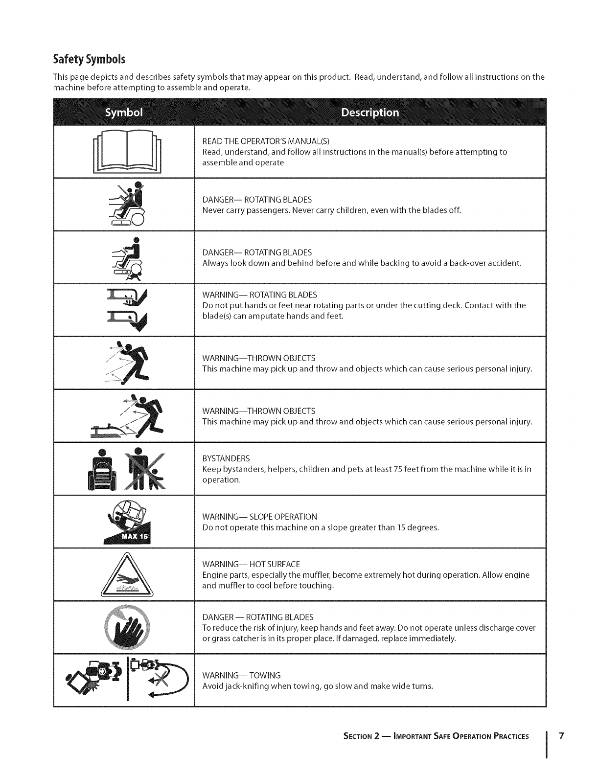
SafetySymbols
This page depicts and describes safety symbols that may appear on this product. Read, understand, and follow all instructions on the
machine before attempting to assemble and operate.
O
J
Lq
M
N
A
READ THE OPERATOR'S MANUAL(S)
Read, understand, and follow all instructions in the manual(s) before attempting to
assemble and operate
DANGER-- ROTATING BLADES
Never carry passengers. Never carry children, even with the blades off.
DANGER-- ROTATING BLADES
Always look down and behind before and while backing to avoid a back-over accident.
WARNING-- ROTATING BLADES
Do not put hands or feet near rotating parts or under the cutting deck. Contact with the
blade(s) can amputate hands and feet.
WARNING--THROWN OBJECTS
This machine may pick up and throw and objects which can cause serious personal injury.
WARNING--THROWN OBJECTS
This machine may pick up and throw and objects which can cause serious personal injury.
BYSTANDERS
Keep bystanders, helpers, children and pets at least 75 feet from the machine while it is in
operation.
WARNING-- SLOPE OPERATION
Do not operate this machine on a slope greater than 15 degrees.
WARNING-- HOT SURFACE
Engine parts, especially the muffler, become extremely hot during operation. Allow engine
and muffler to cool before touching.
DANGER -- ROTATING BLADES
To reduce the risk of injury, keep hands and feet away. Do not operate unless discharge cover
or grass catcher is in its proper place. If damaged, replace immediately.
WARNING-- TOWING
Avoid jack-knifing when towing, go slow and make wide turns.
SECTION 2 -- IMPORTANT SAFE OPERATION PRACTICES 7
co
R
=4
z
I
z
-4
O
z
=o
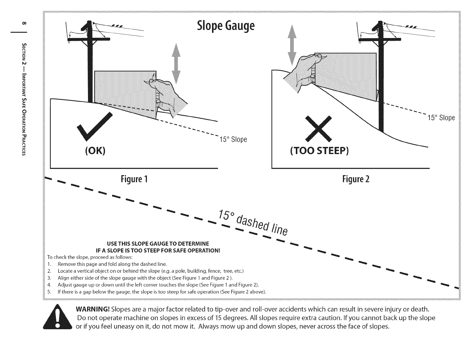
-4 (OK)
15° Slope X
(TOO STEEP)
15° Slope
_Figure1
USE THiS SLOPE GAUGE TO DETERMINE
iF A SLOPE iS TOO STEEP FOR SAFE OPERATION[
To check the slope, proceed as follows:
1. Remove this page and fold along the dashed line.
2. Locate a vertical object on or behind the slope (e.g. a pole, building, fence, tree, etc.)
3. Align either side of the slope gauge with the object (See Figure 1 and Figure 2 ).
4. Adjust gauge up or clown until the left corner touches the slope (See Figure 1 and Figure 2).
5. If there is a gap below the gauge, the slope is too steep for safe operation (See Figure 2 above).
15°das2ed line
Figure2
WARN[NGI Slopes are a major factor related to tip-over and roll-over accidents which can result in severe injury or death.
Do not operate machine on slopes in excess of 15 degrees. All slopes require extra caution. If you cannot back up the slope
or if you feel uneasy on it, do not mow it. Always mow up and down slopes, never across the face of slopes.
Assembly& Set-Up
TractorSet-Up
NOTE:This Operators Manual covers a range of product
specifications for various models. Characteristics and features
discussed and/or illustrated in this manual may not be applicable
to all models. MTD LLC reserves the right to change product
specifications, designs and equipment without notice and
without incurring obligation.
Connecting the Battery Cables
CALIFORNIA PROPOSITION 65 WARNING:
Battery posts, terminals, and related accessories
contain lead and lead compounds, chemicals known
to the State of California to cause cancer and
reproductive harm. Wash hands after handling.
CAUTION: When attaching battery cables, always
connect the POSITIVE (Red) wire to its terminal first,
followed by the NEGATIVE (Black) wire.
For shipping reasons, both battery cables on your equipment
may have been left disconnected from the terminals at the
factory. To connect the battery cables, proceed as follows:
NOTE:The positive battery terminal is marked Pos. (+). The
negative battery terminal is marked Neg. (-).
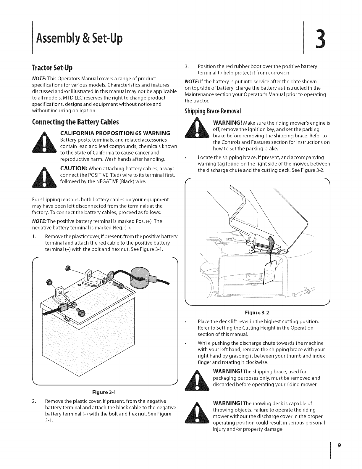
1. Remove the plastic cover, if present, from the positive battery
terminal and attach the red cable to the positive battery
terminal (+) with the bolt and hex nut. See Figure 3-1.
2_
Figure 3-1
Remove the plastic cover, if present, from the negative
battery terminal and attach the black cable to the negative
battery terminal (-) with the bolt and hex nut. See Figure
3-1.
3. Position the red rubber boot over the positive battery
terminal to help protect it from corrosion.
NOTE: If the battery is put into service after the date shown
on top/side of battery, charge the battery as instructed in the
Maintenance section your Operator's Manual prior to operating
the tractor.
Shipping BraceRemoval
WARNING! Make sure the riding mower's engine is
off, remove the ignition key, and set the parking
brake before removing the shipping brace. Refer to
the Controls and Features section for instructions on
how to set the parking brake.
Locate the shipping brace, if present, and accompanying
warning tag found on the right side of the mower, between
the discharge chute and the cutting deck. See Figure 3-2.
f\
Figure 3-2
Place the deck lift lever in the highest cutting position.
Refer to Setting the Cutting Height in the Operation
section of this manual.
While pushing the discharge chute towards the machine
with your left hand, remove the shipping brace with your
right hand by grasping it between your thumb and index
finger and rotating it clockwise.
WARNING!The shipping brace, used for
packaging purposes only, must be removed and
discarded before operating your riding mower.
_I_ WARNING! The mowing deck is capable of
throwing objects. Failure to operate the riding
mower without the discharge cover in the proper
operating position could result in serious personal
injury and/or property damage.
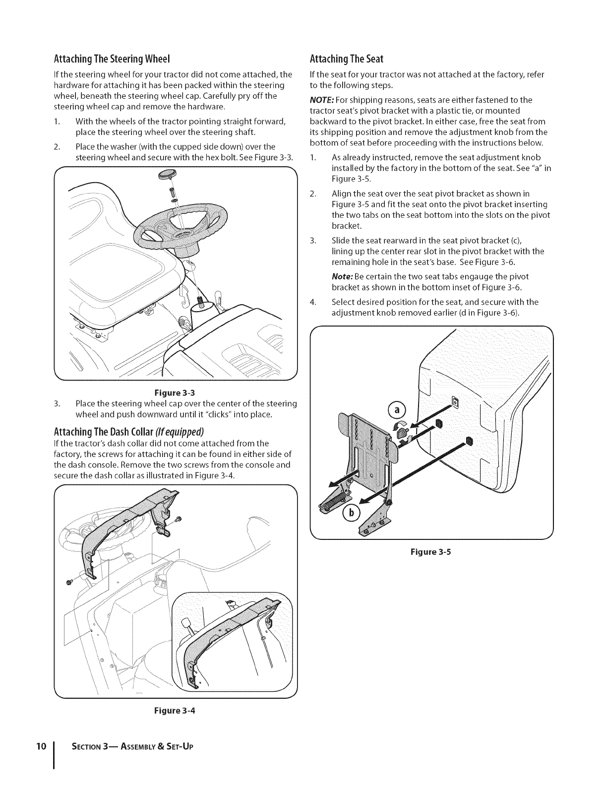
AttachingTheSteering Wheel
If the steering wheel for your tractor did not come attached, the
hardware for attaching it has been packed within the steering
wheel, beneath the steering wheel cap. Carefully pry off the
steering wheel cap and remove the hardware.
1. With the wheels of the tractor pointing straight forward,
place the steering wheel over the steering shaft.
2. Place the washer (with the cupped side down) over the
steering wheel and secure with the hex bolt. See Figure 3-3.
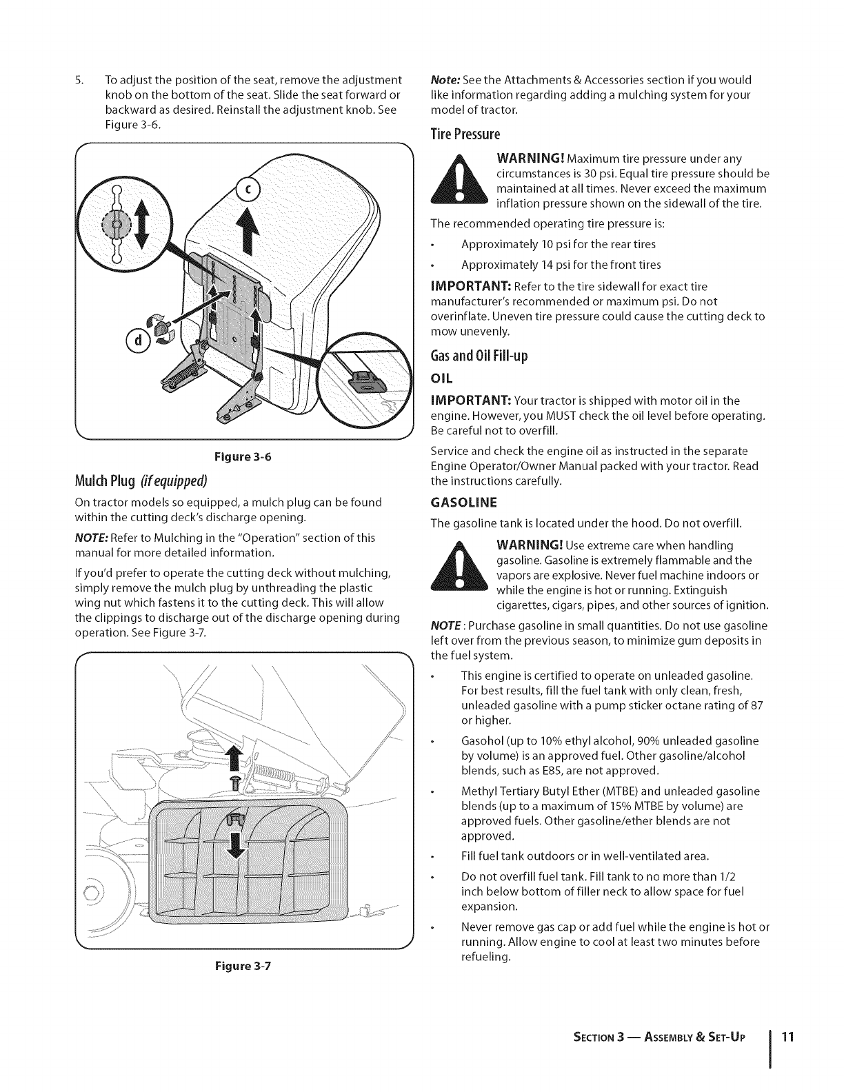
Attaching The Seat
If the seat for your tractor was not attached at the factory, refer
to the following steps.
NOTE: For shipping reasons, seats are either fastened to the
tractor seat's pivot bracket with a plastic tie, or mounted
backward to the pivot bracket. In either case, free the seat from
its shipping position and remove the adjustment knob from the
bottom of seat before proceeding with the instructions below.
1. As already instructed, remove the seat adjustment knob
installed by the factory in the bottom of the seat. See "a" in
Figure 3-5.
2. Align the seat over the seat pivot bracket as shown in
Figure 3-5 and fit the seat onto the pivot bracket inserting
the two tabs on the seat bottom into the slots on the pivot
bracket.
3. Slide the seat rearward in the seat pivot bracket (c),
lining up the center rear slot in the pivot bracket with the
remaining hole in the seat's base. See Figure 3-6.
Note: Be certain the two seat tabs engauge the pivot
bracket as shown in the bottom inset of Figure 3-6.
4. Select desired position for the seat, and secure with the
adjustment knob removed earlier (d in F gure 3-6).
Figure 3-3
3. Place the steering wheel cap over the center of the steering
wheel and push downward until it "clicks" into place.
Attaching TheDashCollarCIfequipped)
If the tractor's dash collar did not come attached from the
factory, the screws for attaching it can be found in either side of
the dash console. Remove the two screws from the console and
secure the dash collar as illustrated in Figure 3-4.
®
Figure 3-5
\ \
Figure 3-4
J
SECTION 3-- ASSEMBLY&SET-UP
5_ To adjust the position of the seat, remove the adjustment
knob on the bottom of the seat. Slide the seat forward or
backward as desired. Reinstall the adjustment knob. See
Figure 3-6.
Figure 3-6
Mulch Plug (if equipped)
On tractor models so equipped, a mulch plug can be found
within the cutting deck's discharge opening.
NOTE: Refer to Mulching in the "Operation" section of this
manual for more detailed information.
If you'd prefer to operate the cutting deck without mulching,
simply remove the mulch plug by unthreading the plastic
wing nut which fastens it to the cutting deck. This will allow
the clippings to discharge out of the discharge opening during
operation. See Figure 3-7.
\
\
/
Figure 3-7
Note: See the Attachments & Accessories section if you would
like information regarding adding a mulching system for your
model of tractor.
TirePressure
WARNING! Maximum tire pressure under any
circumstances is 30 psi. Equal tire pressure should be
maintained at all times. Never exceed the maximum
inflation pressure shown on the sidewall of the tire.
The recommended operating tire pressure is:
Approximately 10 psi for the rear tires
Approximately 14 psi for the front tires
IMPORTANT: Refer to the tire sidewall for exact tire
manufacturer's recommended or maximum psi. Do not
overinflate. Uneven tire pressure could cause the cutting deck to
mow unevenly.
Gasand 0il Fill-up
OIL
IMPORTANT: Your tractor is shipped with motor oil in the
engine. However, you MUST check the oil level before operating.
Be careful not to overfill.
Service and check the engine oil as instructed in the separate
Engine Operator/Owner Manual packed with your tractor. Read
the instructions carefully.
GASOLINE
The gasoline tank is located under the hood. Do not overfill.
WARNING. Use extreme care when handling
gasoline. Gasoline is extremely flammable and the
vapors are explosive. Never fuel machine indoors or
while the engine is hot or running. Extinguish
cigarettes, cigars, pipes, and other sources of ignition.
NOTE: Purchase gasoline in small quantities. Do not use gasoline
left over from the previous season, to minimize gum deposits in
the fuel system.
This engine is certified to operate on unleaded gasoline.
For best results, fill the fuel tank with only clean, fresh,
unleaded gasoline with a pump sticker octane rating of 87
or higher.
Gasohol (up to 10% ethyl alcohol, 90% unleaded gasoline
by volume) is an approved fuel. Other gasoline/alcohol
blends, such as E85, are not approved.
Methyl Tertiary Butyl Ether (MTBE) and unleaded gasoline
blends (up to a maximum of 15% MTBE by volume) are
approved fuels. Other gasoline/ether blends are not
approved.
Fill fuel tank outdoors or in well-ventilated area.
Do not overfill fuel tank. Fill tank to no more than 1/2
inch below bottom of filler neck to allow space for fuel
expansion.
Never remove gas cap or add fuel while the engine is hot or
running. Allow engine to cool at least two minutes before
refueling.
SECTION3-- ASSEMBLY& SET-UP 11
If gasoline is spilled, wipe it off the engine and equipment.
Move machine to another area. Wait 5 minutes before
starting the engine.
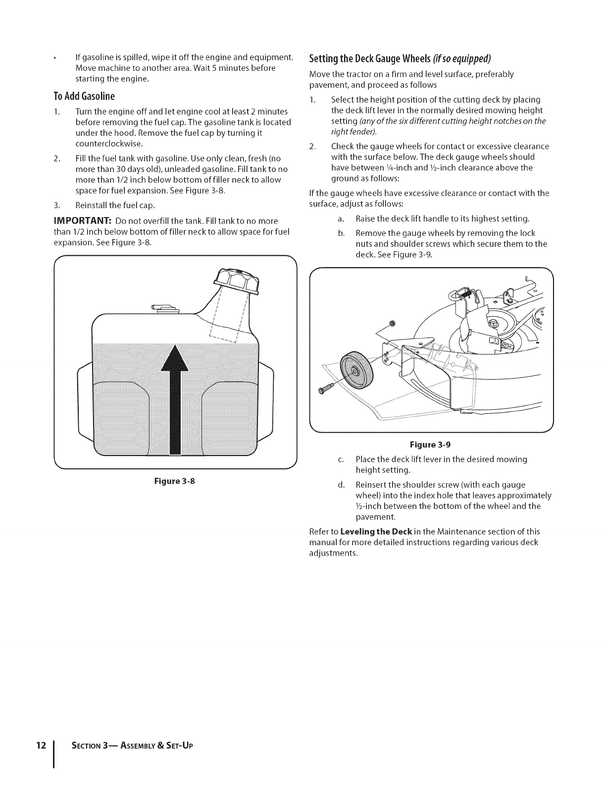
ToAddGasoline
1. Turn the engine off and let engine cool at least 2 minutes
before removing the fuel cap. The gasoline tank is located
under the hood. Remove the fuel cap by turning it
counterclockwise.
2. Fill the fuel tank with gasoline. Use only clean, fresh (no
more than 30 days old), unleaded gasoline. Fill tank to no
more than 1/2 inch below bottom of filler neck to allow
space for fuel expansion. See Figure 3-8.
3. Reinstall the fuel cap.
IMPORTANT: Do not overfill the tank. Fill tank to no more
than 1/2 inch below bottom of filler neck to allow space for fuel
expansion. See Figure 3-8.
Figure 3-8
J
Setting the DeckGaugeWheels(ifsoequipped)
Move the tractor on a firm and level surface, preferably
pavement, and proceed as follows
1. Select the height position of the cutting deck by placing
the deck lift lever in the normally desired mowing height
setting (any of the six different cutting height notches on the
righ t fender).
2. Check the gauge wheels for contact or excessive clearance
with the surface below. The deck gauge wheels should
have between 1/4-inch and 1/2-inch clearance above the
ground as follows:
If the gauge wheels have excessive clearance or contact with the
surface, adjust as follows:
a. Raise the deck lift handle to its highest setting.
b. Remove the gauge wheels by removing the lock
nuts and shoulder screws which secure them to the
deck. See Figure 3-9.
J
Figure 3-9
c. Place the deck lift lever in the desired mowing
height setting.
d. Reinsert the shoulder screw (with each gauge
wheel) into the index hole that leaves approximately
1/2-inch between the bottom of the wheel and the
pavement.
Refer to Leveling the Deck in the Maintenance section of this
manual for more detailed instructions regarding various deck
adjustments.
12 [ SECTION3-- ASSEMBLY& SET-UP
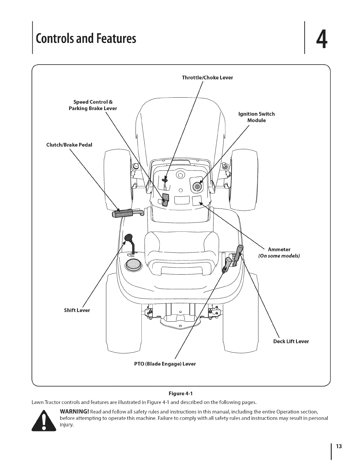
Controlsand Features 4
Throttle/Choke Lever
Speed Control &
Parking Brake Lever ignition Switch
Module
Clutch/Brake Pedal
Ammeter
(On some models)
Shift Lever
Deck Lift Lever
PTO (Blade Engage) Lever
Figure 4=1
Lawn Tractor controls and features are illustrated in Figure 4-1 and described on the following pages.
WARNING! Read and follow all safety rules and instructions in this manual, including the entire Operation section,
before attempting to operate this machine. Failure to comply with all safety rules and instructions may result in personal
injury.
13
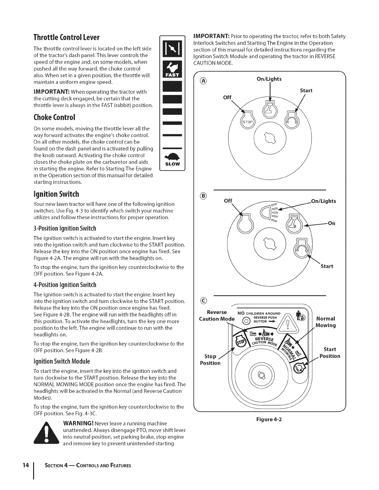
ThrottleControl Lever
The throttle control lever is located on the left side
of the tractor's dash panel. This lever controls the
speed of the engine and, on some models, when
pushed all the way forward, the choke control
also. When set in a given position, the throttle will
maintain a uniform engine speed.
iMPORTANT: When operating the tractor with
the cutting deck engaged, be certain that the
throttle lever is always in the FAST (rabbit) position.
ChokeControl
On some models, moving the throttle lever all the
way forward activates the engine's choke control.
On all other models, the choke control can be
found on the dash panel and is activated by pulling
the knob outward. Activating the choke control
closes the choke plate on the carburetor and aids
in starting the engine. Refer to Starting The Engine
in the Operation section of this manual for detailed
starting instructions.
/
m
H
m
SLOW
Ignition Switch
Your new lawn tractor will have one of the following ignition
switches. Use Fig. 4-3 to identify which switch your machine
utilizes and follow these instructions for proper operation.
3-PositionIgnition Switch
The ignition switch is activated to start the engine. Insert key
into the ignition switch and turn clockwise to the START position.
Release the key into the ON position once engine has fired. See
Figure 4-2A. The engine will run with the headlights on.
To stop the engine, turn the ignition key counterclockwise to the
OFF position. See Figure 4-2A.
4-Position Ignition Switch
The ignition switch is activated to start the engine. Insert key
into the ignition switch and turn clockwise to the START position.
Release the key into the ON position once engine has fired.
See Figure 4-2B. The engine will run with the headlights offin
this position. To activate the headlights, turn the key one more
position to the left. The engine will continue to run with the
headlights on.
To stop the engine, turn the ignition key counterclockwise to the
OFF position. See Figure 4-2B.
Ignition Switch Module
To start the engine, insert the key into the ignition switch and
turn clockwise to the START position. Release the key into the
NORMAL MOWING MODE position once the engine has fired. The
headlights will be activated in the Normal (and Reverse Caution
Modes).
To stop the engine, turn the ignition key counterclockwise to the
OFF position. See Fig. 4-3C.
WARNING! Never leave a running machine
unattended. Always disengage PTO, move shift lever
into neutral position, set parking brake, stop engine
and remove key to prevent unintended starting.
iMPORTANT: Prior to operating the tractor, refer to both Safety
Interlock Switches and Starting The Engine in the Operation
section of this manual for detailed instructions regarding the
Ignition Switch Module and operating the tractor in REVERSE
CAUTION MODE.
(_) On/Lights
off
®Off
Start
_everse NO CHILDREN AROUND
Caution Mode Q BUTToNREVERSEPUSH Normal
Stop
Position
Start
Position
Figure 4-2
SECTION 4 -- CONTROLS AND FEATURES
Clutch-BrakePedal
The clutch-brake pedal is located on the left side of the lawn
tractor, along the running board. Depress the clutch-brake pedal
part way down when slowing the tractor by changing speeds
(Refer to Speed Control Lever). Depress the pedal all the way down
to engage the disc brake and bring the tractor to a complete
stop.
NOTE:The pedal must be depressed to start the engine. Refer to
Safety Interlock Switches in the Operation section of this manual.
ParkingBrake
To set the parking brake, fully depress the clutch-
brake pedal. Move the speed control lever all the
way down and into the parking brake position.
Release the clutch-brake pedal to allow the parking
brake to engage.
To release the parking brake, depress the clutch-
brake pedal and move the speed control lever out
of the notches to the desired position. Release the
speed control lever and the clutch-brake pedal.
NOTE:The parking brake must be set if the
operator leaves the seat with the engine running or
the engine will automatically shut off.
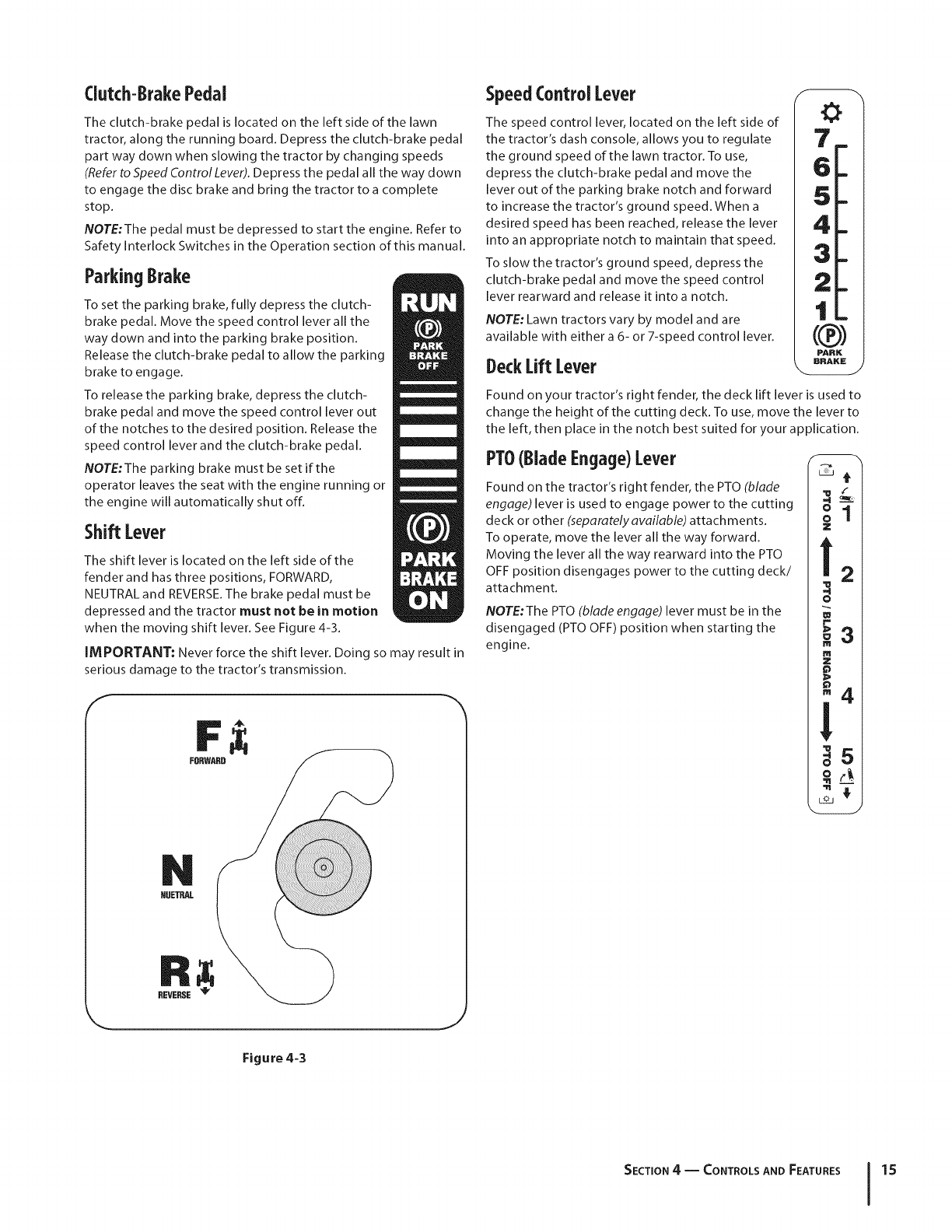
Shift Lever
The shift lever is located on the left side of the
fender and has three positions, FORWARD,
NEUTRAL and REVERSE.The brake pedal must be
depressed and the tractor must not be in motion
when the moving shift lever. See Figure 4-3.
IMPORTANT: Never force the shift lever. Doing so may result in
serious damage to the tractor's transmission.
f
FORWARD
NUETRAL
REVERSE _
Figure 4=3
SpeedControl Lever
The speed control lever, located on the left side of
the tractor's dash console, allows you to regulate
the ground speed of the lawn tractor. To use,
depress the clutch-brake pedal and move the
lever out of the parking brake notch and forward
to increase the tractor's ground speed. When a
desired speed has been reached, release the lever
into an appropriate notch to maintain that speed.
To slow the tractor's ground speed, depress the
clutch-brake pedal and move the speed control
lever rearward and release it into a notch.
NOTE: Lawn tractors vary by model and are
available with either a 6- or 7-speed control lever.
DeckLift Lever
Found on your tractor's right fender, the deck lift lever is used to
change the height of the cutting deck. To use, move the lever to
the left, then place in the notch best suited for your application.
PTO(BladeEngage)Lever
Found on the tractor's right fender, the PTO (blade
engage) lever is used to engage power to the cutting
deck or other (separately available) attachments.
To operate, move the lever all the way forward.
Moving the lever all the way rearward into the PTO
OFF position disengages power to the cutting deck/
attachment.
Z
m
o
m
Z
NOTE:The PTO (blade engage) lever must be in the
disengaged (PTO OFF) position when starting the
engine.
SECTION 4 -- CONTROLS AND FEATURES 15
Operation
TO AVOID SERIOUS INJURY
OR DEATH
•GOUP AND DOWNSLOPES,NOTACROSS.
• AVOIDSUDDENTURNS.
•DONOTOPERATETHE UNITWHERE IT COULDSLIP
ORTIP.
•IF MACHINESTOPSGOINGUPHILL,STOP BLADE(S)
AND BACKDOWNHILLSLOWLY.
•KEEPSAFETYDEVICES(GUARDS,SHIELDS,
AND SWITCHES,ETC.) IN PLACEAND WORKING.
•REMOVEOBJECTSTHATCOULDBE THROWN
BY THE BLADE(S).
•KNOWLOCATIONAND FUNCTIONOF ALL CONTROLS.
•BESUREBLADE(S)AND ENGINEARESTOPPED
BEFOREPLACINGHANDSORFEETNEARBLADE(S).
•BEFORELEAVINGOPERATOR'SPOSITION,
DISENGAGEBLADE(S), ENGAGEPARKINGBRAKE,
SHUT OFFAND REMOVEKEY.
READ OPERATOR'S
MANUAL
SafetyinterlockSwitches
J
This tractor is equipped with a safety interlock system for the
protection of the operator. If the interlock system should ever
malfunction, do not operate the tractor. Contact an authorized
MTD service dealer.
The safety interlock system prevents the engine from
cranking or starting unless the parking brake is engaged,
and the PTO (Blade Engage) lever is in the disengaged (OFF)
position.
The engine will automatically shut off if the operator leaves
the seat before engaging the parking brake.
The engine will automatically shut off if the operator leaves
the tractor's seat with the PTO (Blade Engage) lever in the
engaged (ON) position, regardless of whether the parking
brake is engaged.
Modelswithout ReverseCautionMode
The engine will automatically shut off if the PTO (Blade
Engage) lever is moved into the engaged (ON) position with
the shift lever in Reverse.
Modelswith ReverseCautionMode
With the ignition key in the NORMAL MOWING position,
the engine will automatically shut off if the PTO (Blade
Engage) lever is moved into the engaged (ON) position with
the shift lever in Reverse.
WARNING! Do not operate the tractor if the
interlock system is malfunctioning. This system was
designed for your safety and protection.
ReverseCaution Mode
(Modelsequippedwithignitionswitchmodule)
WARNING! Use extreme caution while operating
the tractor in the REVERSE CAUTION MODE. Always
look down and behind before and while backing. Do
not operate the tractor when children or others are
around. Stop the tractor immediately if someone
enters the area.
The REVERSE CAUTION MODE position of the key switch
module allows the tractor to maneuver in reverse with the blades
(PTO) engaged.
IMPORTANT: Mowing in reverse is not recommended.
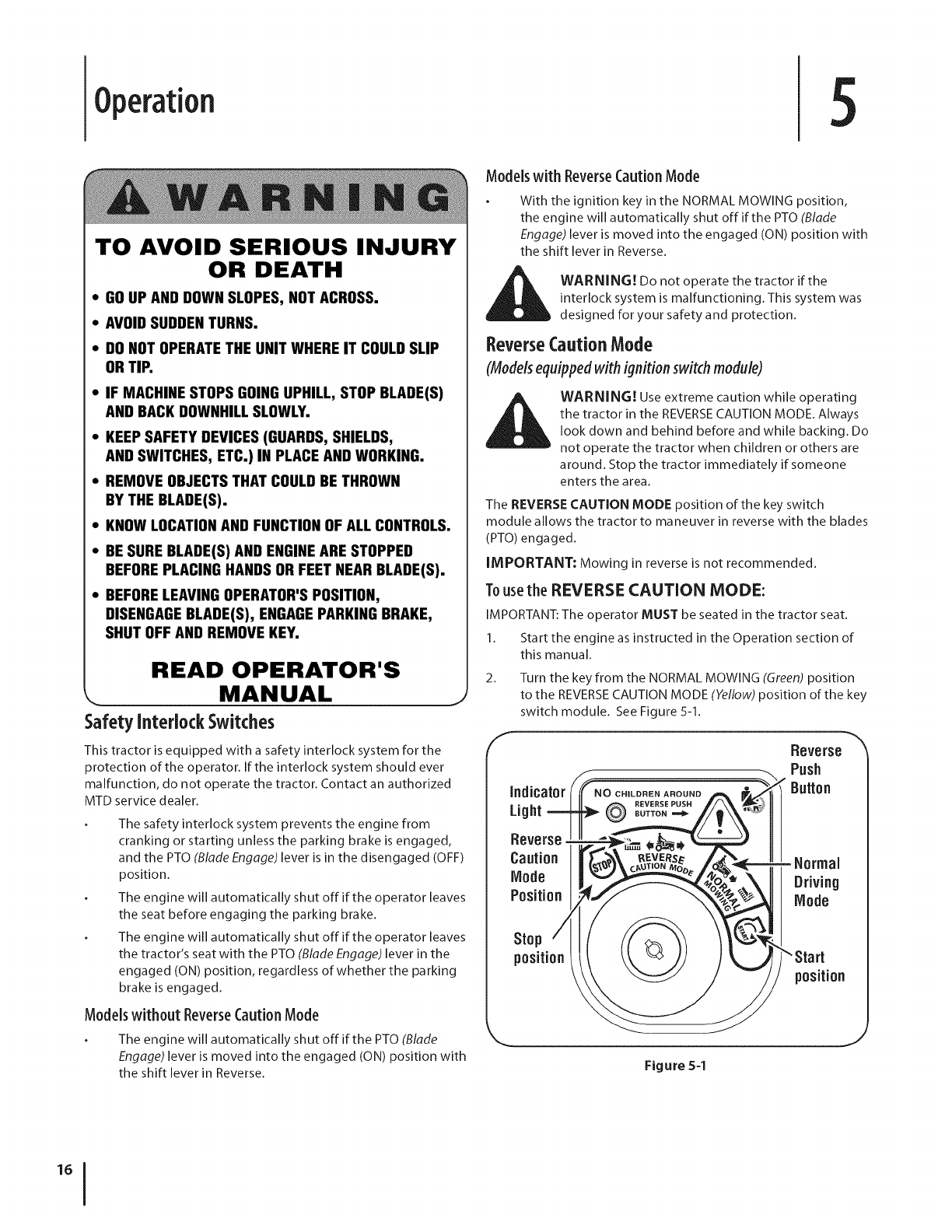
Tousethe REVERSE CAUTION MODE:
IMPORTANT: The operator MUST be seated in the tractor seat.
1. Start the engine as instructed in the Operation section of
this manual.
2. Turn the key from the NORMAL MOWING (Green) position
to the REVERSECAUTION MODE (Yellow) position of the key
switch module. See Figure 5-1.
f
Indicator
Light REVERSEPUSH
BUTTON ==d_
Reverse
Push
Button
Reverse
Caution
Mode
Position
=Normal
Driving
Mode
Stop
position Start
position
Figure 5-1
J
3.
4.
5.
6.
Depress the REVERSE PUSH BUTTON (Orange, Triangular
Button) at the top, right corner of the key switch rood ule.
The red indicator light at the top, left corner of the key
switch module will be ON while activated. See Figure 5-1.
Once activated (indicator light ON), the tractor can be driven
in reverse with the cutting blades (PTO) engaged.
Always look down and behind before and while backing to
make sure no children are around.
After resuming forward motion, return the key to the
NORMAL MOWING position.
IMPORTANT: The REVERSECAUTION MODE will remain
activated until:
a.
b.
The key is placed in either the NORMAL MOWING
position or STOP position.
The operator engages the parking brake by fully
depressing the clutch-brake pedal and holding it
down while moving the speed control lever into the
PARK BRAKE position.
Engagingthe ParkingBrake
Toengagethe parkingbrake:
1. Fully depress the clutch-brake pedal and hold it down with
your foot.
2. Move the speed control lever all the way down and into the
parking brake position.
3. Release the clutch-brake pedal to allow the parking brake
to engage.
Toreleasethe parkingbrake:
1. Depress the clutch-brake pedal and move the speed
control lever out of the parking brake position and into a
desired speed.
Setting the Cutting Height
1. Select the height position of the cutting deck by placing
the deck lift lever in any of the six different cutting height
notches on the right side of the fender.
2. Adjust the deck wheels as instructed in the Assembly & Set-
Up section earlier in this manual, if equipped, so that they
are between 1/4-inch and 1/2-inch above the ground when
the tractor is on a smooth, flat surface such as a driveway.
i_ WARNING! Keep hands and feet away from the
discharge opening of the cutting deck.
NOTE: On models so equipped, the deck wheels are an anti-scalp
feature of the deck and are not designed to support the weight
of the cutting deck. Refer to Leveling in the Maintenance section
of this manual for more detailed instructions regarding various
deck adjustments.
Starting the Engine
__, ARNING! Do not operate the tractor if the
interlock system is malfunctioning. This system was
designed for your safety and protection.
NOTE: Refer to the Gasoline and Oil fill-up instructions in the
separate Engine Operator's manual included with this tractor.
1. Insert the tractor key into the ignition switch.
2. Place the PTO (Blade Engage) lever in the disengaged (OFF)
position.
3. Engage the tractor's parking brake.
4. Activate the choke control.
5. Turn the ignition key clockwise to the START position. After
the engine starts, release the key. It will return to the ON (or
Normal Mowing) position.
_CAUTION: Do NOT hold the key in the START
position for longer than ten seconds at a time. Doing
so may cause damage to your engine's electric
starter.
6. After the engine starts, deactivate the choke control and
place the throttle control in the FAST position.
NOTE: Do NOT leave the choke control on while operating the
tractor. Doing so will result in a "rich" fuel mixture and cause the
engine to run poorly.
Stepping the Engine
WARNING! Ifyou strike a foreign object, stop the
engine, disconnect the spark plug wire(s) and
ground against the engine. Thoroughly inspect the
machine for any damage. Repair the damage before
restarting and operating
1. If the blades are engaged, place the PTO (Blade Engage)
lever in the disengaged (OFF) position.
2. Turn the ignition key counterclockwise to the STOP
position.
3. Remove the key from the ignition switch to prevent
unintended starting.
SECTION 5 -- OPERATION 17
Driving TheTractor
1.
2.
3.
WARNING! Avoid sudden starts, excessive speed
and sudden stops.
WARNING! Do not leave the seat of the tractor
without first placing the PTO (Blade Engage) lever in
the disengaged (OFF) position, depressing the brake
pedal and engaging the parking brake. If leaving
the tractor unattended, also turn the ignition key off
and remove the key.
WARNING! Always look down and behind before
and while backing up to avoid a back-over accident.
Depress the brake pedal to release the parking brake and
let the pedal up.
Move the throttle lever into the FAST (rabbit) position.
Place the shift lever in either the FORWARD or REVERSE
position.
IMPORTANT: Do NOT use the shift lever to change the
direction of travel when the tractor is in motion. Always use
the brake pedal to bring the tractor to a complete stop before
shifting.
4. Releasethe parking brake by depressing the clutch-brake
pedal and positioning the speed control lever in desired
position.
IMPORTANT: First-time operators should use speed positions 1
or 2. Become completely familiar with the tractor's operation and
controls before operating the tractor in higher speed positions.
5. Release clutch-brake pedal slowly to put unit into motion.
6. The lawn tractor is brought to a stop by depressing the
clutch-brake pedal.
NOTE:When operating the unit initially, there will be little
difference between the highest two speeds until after the belts
have seated themselves into the pulleys during the break-in
period.
WARNING! Before leaving the operator's position
for any reason, disengage the blades, place the shift
lever in neutral, engage the parking brake, shut
engine offand remove the key.
IMPORTANT: When stopping the tractor for any reason while
on a grass surface, always:
1. Placethe shift lever in neutral,
2. Engage the parking brake,
3. Shut engine off and remove the key. Doing so will minimize
the possibility of having your lawn "browned" by hot
exhaust from your tractor's running engine.
If unit stalls with speed control in high speed, or if unit will
not operate with speed control lever in a low speed position,
proceed as follows:
1. Place shift lever in NEUTRAL.
2. Restart engine.
3. Place speed control lever in highest speed position.
4. Release clutch-brake pedal fully.
5. Depress clutch-brake pedal.
6. Place speed control lever in desired position.
7. Place shift lever in either FORWARD or REVERSE,and follow
normal operating procedures.
Driving OnSlopes
Refer to the SLOPEGAUGEin the Important Safe Operation
Practices section of the manual to help determine slopes where
you may operate the tractor safely.
WARNING! Do not mow on inclines with a slope in
excessof 15degrees (a riseof approximately2-1/2 feet
every 10feet).The tractor could overturn and cause
serious injury.
Mow up and down slopes, NEVERacross.
Exercise extreme caution when changing direction on
slopes.
Watch for holes, ruts, bumps, rocks, or other hidden
objects. Uneven terrain could overturn the machine. Tall
grass can hide obstacles.
Avoid turns when driving on a slope. Ira turn must be
made, turn down the slope. Turning up a slope greatly
increases the chance of a roll over.
Avoid stopping when driving up a slope. If it is necessary
to stop while driving up a slope, start up smoothly and
carefully to reduce the possibility of flipping the tractor
over backward.
Engagingthe Blades
Engaging the PTO (Blade Engage) transfers power to the cutting
deck or other (separately available) attachments. To engage the
blades, proceed as follows:
1. Move the throttle control lever to the FAST (rabbit)
position.
2. Grasp the PTO (Blade Engage) lever and pivot it all the way
forward into the engaged (ON) position.
3. Keep the throttle lever in the FAST (rabbit) position for the
most efficient use of the cutting deck or other (separately
available) attachments.
Modelswith ReverseCautionMode:
The engine will automatically shut off if the PTOis engaged with
the shift lever in position for reverse travel with the ignition key
in the NORMAL MOWING position.
Modelswithout ReverseCaution Mode:
The PTO(Blade Engage) lever must be in the disengaged (OFF)
position when starting the engine, when traveling in reverse, and
if the operator leaves the seat. Refer to Safety Interlock Switches
in the Operation section of this manual.
Usingthe DeckLift Lever
To raise the cutting deck, move the deck lift lever to the left, then
place it in the notch best suited for your application. Refer to
Setting The Cutting Height earlier in this section.
SECTION S-- OPERATION
WARNING! To help avoid blade contact or a
thrown object injury, keep bystanders, helpers,
children and pets at least 75 feet from the machine
while it is in operation. Stop machine if anyone
enters the area.
The following information will be helpful when using the cutting
deck with your tractor:
WARNING! Plan your mowing pattern to avoid
discharge of materials toward roads, sidewalks,
bystanders and the like. Also, avoid discharging
material against a wall or obstruction which may
cause discharged material to ricochet back toward
the operator.
Do not mowat high ground speed, especially ira mulch kit
or grass collector is installed.
For best results it is recommended that the first two laps be
cut with the discharge thrown towards the center. After the
first two laps, reverse the direction to throw the discharge
to the outside for the balance of cutting. This will give a
better appearance to the lawn.
Do not cut the grass too short. Short grass invites weed
growth and yellows quickly in dry weather.
Mowing should always be done with the engine at full throttle.
Under heavier conditions it may be necessary to go back
over the cut area a second time to get a clean cut.
Do NOT attempt to mow heavy brush and weeds and
extremely tall grass. Your tractor is designed to mow lawns,
NOT clear brush.
Keep the blades sharp and replace the blades when worn.
Refer to Cutting Blades in the Service section of this manual
for proper blade sharpening instructions.
Mulching
Select models come equipped with a mulch kit which
incorporates special blades, already standard on the tractor, in a
process of recirculating grass clippings repeatedly beneath the
cutting deck. The ultra-fine clippings are then forced back into
the lawn where they act as a natural fertilizer.
Observe the following points for the best results when mulching:
Never attempt to mulch if the lawn is damp. Wet grass
tends to stick to the underside of the cutting deck
preventing proper mulching of the clippings.
Do NOT attempt to mulch more than 1/3 the total height of
the grass or approximately 1-1/2 inches. Doing so will cause
the clippings to clump up beneath the deck and not be
mulched effectively.
Maintain a slow ground speed to allow the grass clippings
more time to effectively be mulched.
Always position the throttle control lever in the FAST
(rabbit) position and allow it to remain there while mowing.
Failing to keep the engine at full throttle places strain
on the tractor's engine and does not allow the blades to
properly mulch grass. Ground speed should be controlled
using the speed control lever.
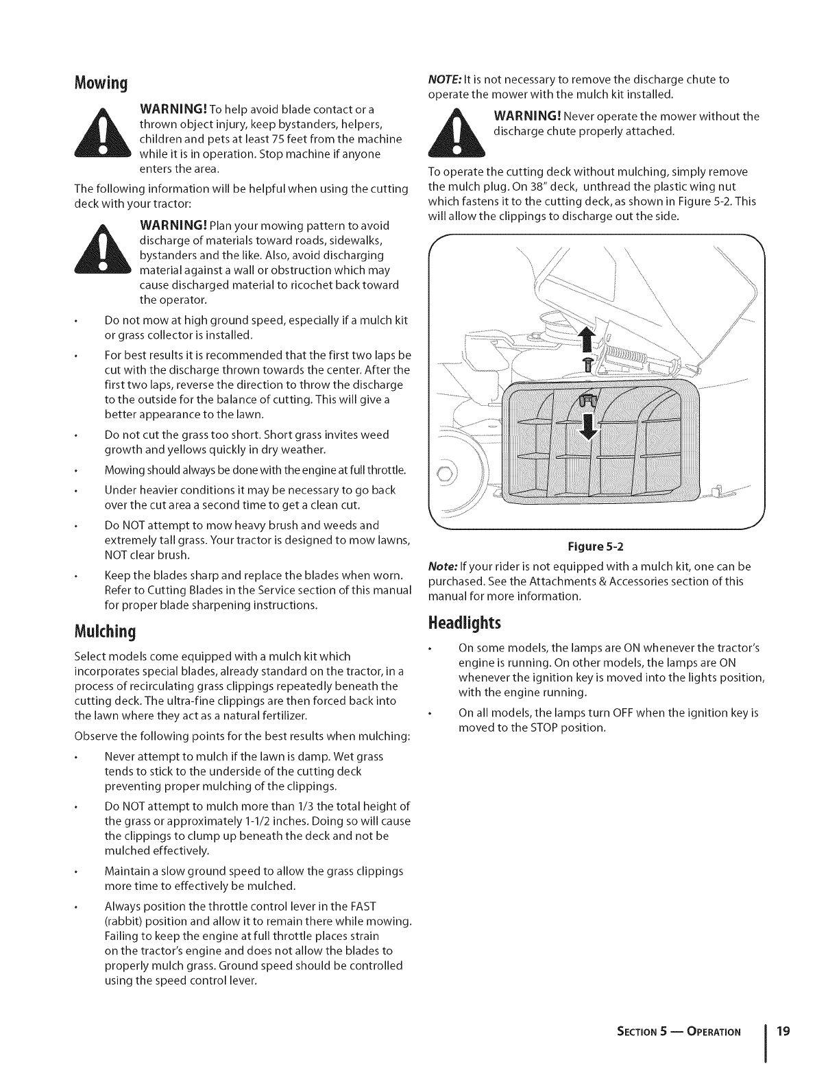
NOTE: It is not necessary to remove the discharge chute to
operate the mower with the mulch kit installed.
WARNING! Never operate the mower without the
discharge chute properly attached.
To operate the cutting deck without mulching, simply remove
the mulch plug. On 38" deck, unthread the plastic wing nut
which fastens it to the cutting deck, as shown in Figure 5-2. This
will allow the clippings to discharge out the side.
Y
....\//// '\\/'/'
\//.
Figure 5=2
Note: If your rider is not equipped with a mulch kit, one can be
purchased. Seethe Attachments & Accessories section of this
manual for more information.
Headlights
On some models, the lamps are ONwhenever the tractor's
engine is running. On other models, the lamps are ON
whenever the ignition key is moved into the lights position,
with the engine running.
On all models, the lamps turn OFFwhen the ignition key is
moved to the STOPposition.
SECTION S -- OPERATION 19
Maintenance& Adjustments 6
Maintenance
WARNING! Before performing any maintenance or
repairs, disengage PTO, move shift lever into neutral
position, set parking brake, stop engine and remove
key to prevent unintended starting.
Refer to the Engine Operator/Owner Manual for engine
maintenance instructions.
Check engine oil level before each use as instructed in the Engine
Operator/Owner Manual packed with your unit. Follow the
instructions carefully.
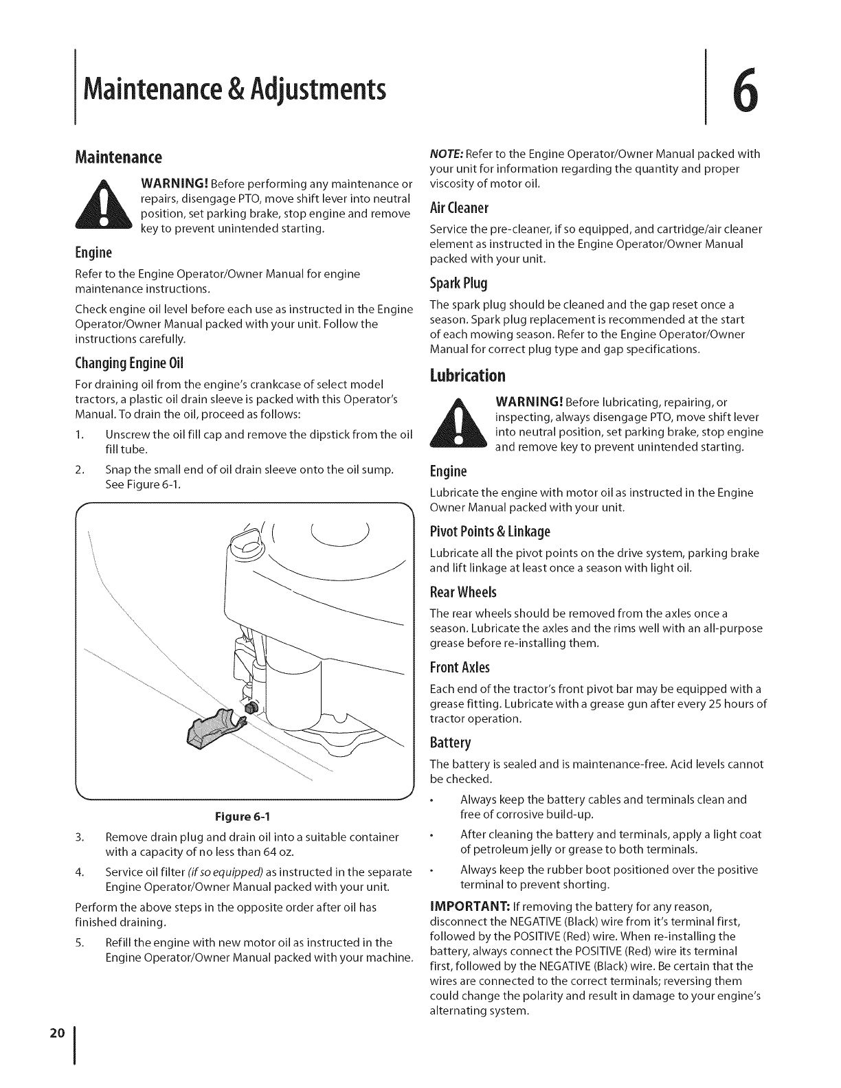
ChangingEngineOil
For draining oil from the engine's crankcase of select model
tractors, a plastic oil drain sleeve is packed with this Operator's
Manual. To drain the oil, proceed as follows:
1. Unscrew the oil fill cap and remove the dipstick from the oil
fill tube.
2. Snap the small end ofoil drain sleeve onto the oil sump.
See Figure 6-1.
k,__ j
Figure 6-1
3. Remove drain plug and drain oil into a suitable container
with a capacity of no less than 64 oz.
4. Service oil filter (ifso equipped) as instructed in the separate
Engine Operator/Owner Manual packed with your unit.
Perform the above steps in the opposite order after oil has
finished draining.
5. Refill the engine with new motor oil as instructed in the
Engine Operator/Owner Manual packed with your machine.
NOTE: Refer to the Engine Operator/Owner Manual packed with
your unit for information regarding the quantity and proper
viscosity of motor oil.
Air Cleaner
Service the pre-cleaner, if so equipped, and cartridge/air cleaner
element as instructed in the Engine Operator/Owner Manual
packed with your unit.
Spark Plug
The spark plug should be cleaned and the gap reset once a
season. Spark plug replacement is recommended at the start
of each mowing season. Refer to the Engine Operator/Owner
Manual for correct plug type and gap specifications.
Lubrication
WARNING! Before lubricating, repairing, or
inspecting, always disengage PTO, move shift lever
into neutral position, set parking brake, stop engine
and remove key to prevent unintended starting.
Engine
Lubricate the engine with motor oil as instructed in the Engine
Owner Manual packed with your unit.
Pivot Points& Linkage
Lubricate all the pivot points on the drive system, parking brake
and lift linkage at least once a season with light oil.
RearWheels
The rear wheels should be removed from the axles once a
season. Lubricate the axles and the rims well with an all-purpose
grease before re-installing them.
FrontAxles
Each end of the tractor's front pivot bar may be equipped with a
grease fitting. Lubricate with a grease gun after every 25 hours of
tractor operation.
Battery
The battery is sealed and is maintenance-free. Acid levels cannot
be checked.
Always keep the battery cables and terminals clean and
free of corrosive build-up.
After cleaning the battery and terminals, apply a light coat
of petroleum jelly or grease to both terminals.
Always keep the rubber boot positioned over the positive
terminal to prevent shorting.
IMPORTANT: If removing the battery for any reason,
disconnect the NEGATIVE (Black) wire from it's terminal first,
followed by the POSITIVE (Red) wire. When re-installing the
battery, always connect the POSITIVE (Red) wire its terminal
first, followed by the NEGATIVE (Black) wire. Be certain that the
wires are connected to the correct terminals; reversing them
could change the polarity and result in damage to your engine's
alternating system.
CleaningBattery
Clean the battery by removing it from the tractor and washing
with a baking soda and water solution. If necessary, scrape the
battery terminals with a wire brush to remove deposits. Coat
terminals and exposed wiring with grease or petroleum jelly to
prevent corrosion.
Battery Failures
Some common causes for battery failure are:
Incorrect initial activation
Overcharging
Freezing
Undercharging
Corroded connections
These failures are NOT covered by your tractor's warranty.
Cleaningthe EngineAndDeck
Any fuel or oil spilled on the machine should be wiped off
promptly. Do NOT allow debris to accumulate around the cooling
fins of the engine or on any other part of the machine.
IMPORTANT: The use of a pressure washer to clean your
tractor is NOT recommended. It may cause damage to electrical
components, spindles, pulle/s, bearings or the engine.
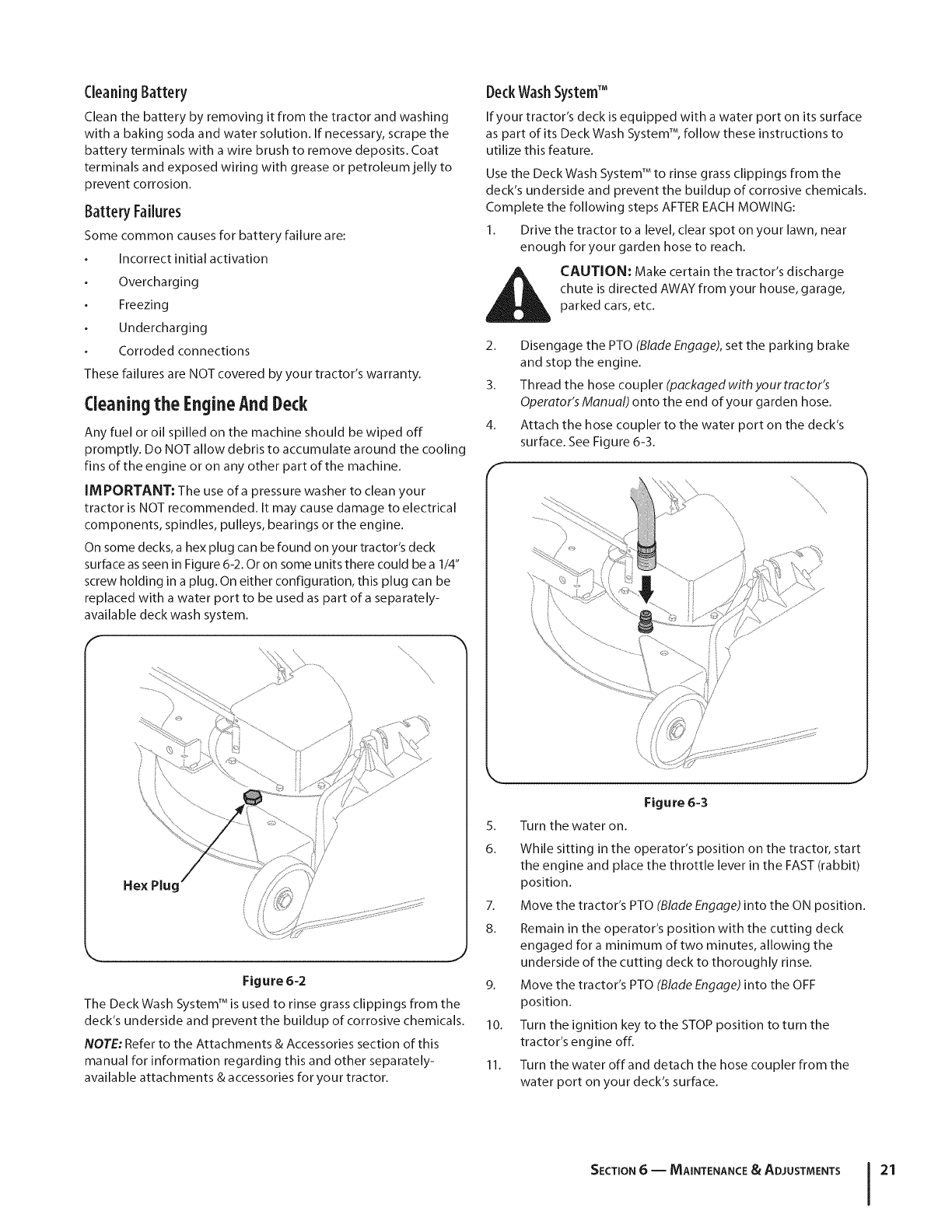
On some decks, a hex plug can be found on your tractor's deck
surface as seen in Figure 6-2. Or on some units there could be a I/4"
screw holding in a plug. On either configuration, this plug can be
replaced with a water port to be used as part of a separately-
available deck wash system.
Hex Plug
Figure 6=2
The DeckWash System TM is used to rinse grass clippings from the
deck's underside and prevent the buildup of corrosive chemicals.
NOTE: Refer to the Attachments & Accessories section of this
manual for information regarding this and other separately-
available attachments & accessories for your tractor.
DeckWashSystemTM
If your tractor's deck is equipped with a water port on its surface
as part of its Deck Wash System% follow these instructions to
utilize this feature.
Use the Deck Wash System TM to rinse grass clippings from the
deck's underside and prevent the buildup of corrosive chemicals.
Complete the following steps AFTER EACH MOWING:
1. Drive the tractor to a level, clear spot on your lawn, near
enough for your garden hose to reach.
CAUTION: Make certain the tractor's discharge
chute is directed AWAY from your house, garage,
parked cars, etc.
2. Disengage the PTO (Blade Engage), set the parking brake
and stop the engine.
3. Thread the hose coupler (packagedwithyourtractor's
Operator's Manual) onto the end of your garden hose.
4. Attach the hose coupler to the water port on the deck's
surface. See Figure 6-3.
f
5.
Figure 6-3
Turn the water on.
6. While sitting in the operator's position on the tractor, start
the engine and place the throttle lever in the FAST (rabbit)
position.
7. Move the tractor's PTO (Blade Engage) into the ON position.
8. Remain in the operator's position with the cutting deck
engaged for a minimum of two minutes, allowing the
underside of the cutting deck to thoroughly rinse.
9. Move the tractor's PTO (Blade Engage) into the OFF
position.
10. Turn the ignition key to the STOP position to turn the
tractor's engine off.
11. Turn the water off and detach the hose coupler from the
water port on your deck's surface.
SECTION 6-- MAINTENANCE & ADJUSTMENTS 21
12. On 46" decks, repeat steps 4 through 11 on the opposite
side of the cutting deck.
IMPORTANT: After cleaning your deck with the Deck Wash
System TM, return to the operator's position and engage the PTO.
Keep the cutting deck running for a minimum of two minutes,
allowing the underside of the cutting deck to thoroughly dry.
Adjustments
i_ WARNI NG! Never attempt to make any
adjustments while the engine is running, except
where specified in the operator's manual.
Levelingthe Deck
NOTE: Check the tractor's tire pressure before performing any
deck leveling adjustments. Refer to Tires in the Service section of
this manual for more information regarding tire pressure.
Front ToRear
The front of the cutting deck is supported by a stabilizer bar that
can be adjusted to level the deck from front to rear. The front of
the deck should be between 1/4-inch and %-inch lower than the
rear of the deck. Adjust if necessary as follows:
1. With the tractor parked on a firm, level surface, place the
lever for lifting the platform on the second to the top notch
(second highest position) and rotate the blade as close to
the discharge channel that is parallel to the tractor.
2. Measure the distance from the front of the blade tip to
the ground and the rear of the blade tip to the ground.
The first measurement taken should be between 1/4"and
%" less than the second measurement. Determine the
approximate distance necessary for proper adjustment and
proceed, if necessary, to the next step.
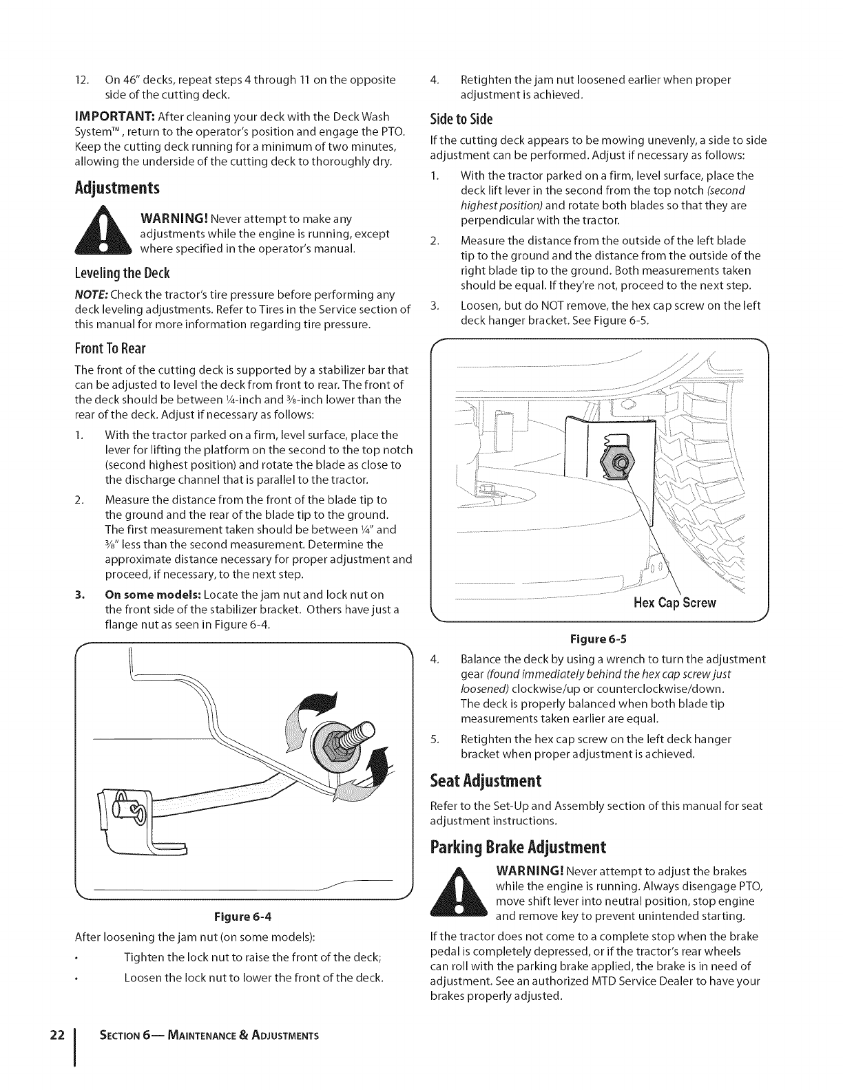
3. On some models: Locate the jam nut and lock nut on
the front side of the stabilizer bracket. Others have just a
flange nutas seen in Figure 6-4.
Figure 6-4
After loosening the jam nut (on some models):
Tighten the lock nut to raise the front of the deck;
Loosen the lock nut to lower the front of the deck.
4. Retighten the jam nut loosened earlier when proper
adjustment is achieved.
Sideto Side
If the cutting deck appears to be mowing unevenly, a side to side
adjustment can be performed. Adjust if necessary as follows:
1. With the tractor parked on a firm, level surface, place the
deck lift lever in the second from the top notch (second
highest position) and rotate both blades so that they are
perpendicular with the tractor.
2. Measure the distance from the outside of the left blade
tip to the ground and the distance from the outside of the
right blade tip to the ground. Both measurements taken
should be equal. If they're not, proceed to the next step.
3. Loosen, but do NOT remove, the hex cap screw on the left
deck hanger bracket. See Figure 6-5.
HexCap Screw
Figure 6-5
4. Balance the deck by using a wrench to turn the adjustment
gear (found immediately behind the hex cap screw just
loosened) clockwise/up or counterclockwise/down.
The deck is properly balanced when both blade tip
measurements taken earlier are equal.
5. Retighten the hex cap screw on the left deck hanger
bracket when proper adjustment is achieved.
SeatAdjustment
Refer to the Set-Up and Assembly section of this manual for seat
adjustment instructions.
ParkingBrakeAdjustment
WARNI NG! Never attempt to adjust the brakes
while the engine is running. Always disengage PTO,
move shift lever into neutral position, stop engine
and remove key to prevent unintended starting.
If the tractor does not come to a complete stop when the brake
pedal is completely depressed, or if the tractor's rear wheels
can roll with the parking brake applied, the brake is in need of
adjustment. See an authorized MTD Service Dealer to have your
brakes properly adjusted.
SECTION 6-- MAINTENANCE & ADJUSTMENTS

MaintenanceSchedule
Before
Eachuse
Every
lOHours
,/
Every
25Hours
Every
50Hours
Every
I00 Hours
Prior
to Storing
,/CleanHood/DashLouvers
CheckEngineOilLevel _" _"
CheckAirFilter for Dirty, Looseor DamagedParts V /
Cleanand Re-oilAirFilter'sFoamPre-deaner V /
ReplaceAirFilter Element
ChangeEngineOilandReplaceOilFilter _"
CleanBatteryTerminals M/M/
LubeFrontAxlesandRims _" _"
CleanEngineCoolingFins _/ _/
LubePedalPivotPoints V /V/
CheckSparkPlugCondition& Gap V /V/
ReplaceFuelFilter V /
NOTE:This Operators Manual covers a range of product specifications for various models. Characteristics and features discussed and/
or illustrated in this manual may not be applicable to all models. MTD LLC reserves the right to change product specifications, designs
and equipment without notice and without incurring obligation.
IMPORTANT: Since this manual covers a range of various tractor models, it is important to consult the specific engine operator's
manual included with this machine for detailed engine maintenance procedures and intervals.
SECTION 6-- MAINTENANCE & ADJUSTMENTS 23
Service 7
Cutting DeckRemoval
NOTE: Models equipped with a 38-inch deck have one deck idler
pulley. Models equipped with a 42- and 46-inch deck have two
deck idler pulleys.
To remove the cutting deck, proceed as follows:
1. Place the PTO (Blade Engage) lever in the disengaged (OFF)
position and engage the parking brake.
2. Lower the deck by moving the deck lift lever into the
bottom notch on the right fender.
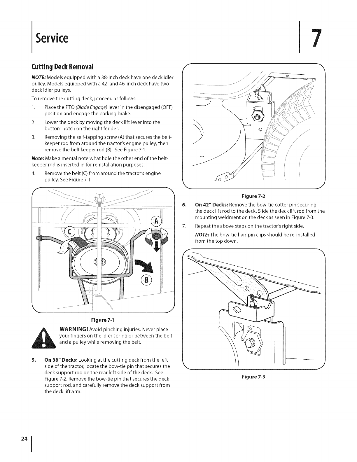
3. Removing the self-tapping screw (A) that secures the belt-
keeper rod from around the tractor's engine pulley, then
remove the belt keeper rod (B). See Figure 7-1.
Note: Make a mental note what hole the other end of the belt-
keeper rod is inserted in for reinstallation purposes.
4. Remove the belt (C) from around the tractor's engine
pulley. See Figure 7-1.
F
6_
7_
\
Figure 7-2
On 42" Decks: Remove the bow-tie cotter pin securing
the deck lift rod to the deck. Slide the deck lift rod from the
mounting weldment on the deck as seen in Figure 7-3.
Repeat the above steps on the tractor's right side.
NOTE:The bow-tie hair-pin clips should be re-installed
from the top down.
Figure 74
WARNING! Avoid pinching injuries. Never place
your fingers on the idler spring or between the belt
and a pulley while removing the belt.
On 38" Decks: Looking at the cutting deck from the left
side of the tractor, locate the bow-tie pin that secures the
deck support rod on the rear left side of the deck. See
Figure 7-2. Remove the bow-tie pin that secures the deck
support rod, and carefully remove the deck support from
the deck lift arm.
\
Figure 7-3
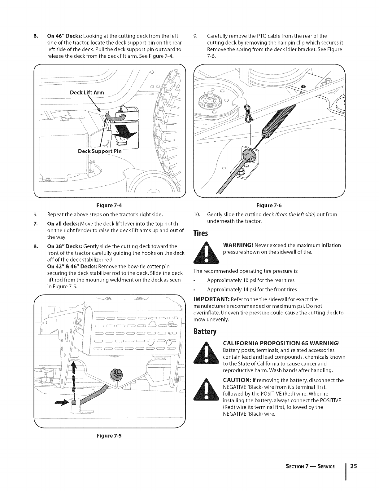
8. On 46" Decks: Looking at the cutting deck from the left
side of the tractor, locate the deck support pin on the rear
left side of the deck. Pull the deck support pin outward to
release the deck from the deck lift arm. See Figure 7-4.
9. Carefully remove the PTOcable from the rear of the
cutting deck by removing the hair pin clip which secures it.
Remove the spring from the deck idler bracket. See Figure
7-6.
Deck Lift Arm
Deck Support Pin
9.
7.
8.
Figure 7-4
Repeat the above steps on the tractor's right side.
On all decks: Move the deck lift lever into the top notch
on the right fender to raise the deck lift arms up and out of
the way.
On 38" Decks: Gently slide the cutting deck toward the
front of the tractor carefully guiding the hooks on the deck
off of the deck stabilizer rod.
On 42" & 46" Decks: Remove the bow-tie cotter pin
securing the deck stabilizer rod to the deck. Slide the deck
lift rod from the mounting weldment on the deck as seen
in Figure 7-5.
.................
..............._<_ ................. ..................................
Figure 7-6
10. Gently slide the cutting deck (from the leftside) out from
underneath the tractor.
Tires
i_i WARNING! Never exceed the maximum inflation
pressure shown on the sidewall of tire.
The recommended operating tire pressure is:
Approximately 10 psi for the rear tires
Approximately 14 psi for the front tires
IMPORTANT: Refer to the tire sidewall for exact tire
manufacturer's recommended or maximum psi. Do not
overinflate. Uneven tire pressure could cause the cutting deck to
mow unevenly.
Battery
CALIFORNIA PROPOSITION 65 WARNING!
Battery posts, terminals, and related accessories
contain lead and lead compounds, chemicals known
to the State of California to cause cancer and
reproductive harm. Wash hands after handling.
CAUTION: If removing the battery, disconnect the
NEGATIVE (Black) wire from it's terminal first,
followed by the POSITIVE (Red) wire. When re-
installing the battery, always connect the POSITIVE
(Red) wire its terminal first, followed by the
NEGATIVE (Black) wire.
Figure 7-5
SECTION7 -- SERVICE 25
JumpStarting
i_ WARNING! Never jump start a damaged or frozen
battery. Be certain the vehicles do not touch, and
ignitions are off. Do not allow cable clamps to touch.
I. Connect positive (+) cable to positive post (+) of your
tractor's discharged battery.
2. Connect the other end of the cable to the (positive +) post
of the jumper battery.
3. Connect the second cable (negative -) to the other post of
the jumper battery.
4. Make the final connection on the engine block of the
tractor, away from the battery. Attach to a unpainted part
to assure a good connection.
CAUTION: If the jumper battery is installed on a
vehicle (i.e. car, truck), do NOT start the vehicle's
engine when jump starting your tractor.
5. Start the tractor (as instructed in the Operation section of
this manual).
6. Set the tractor's parking brake before removing the jumper
cables, in reverse order of connection.
Charging
WARNING! Batteries give off an explosive gas
while charging. Charge the battery in a well
ventilated area and keep away from an open flame
or pilot light as on a water heater, space heater,
furnace, clothes dryer or other gas appliances.
CAUTION: When charging your tractor's battery,
use only a charger designed for 12V lead-acid
batteries. Read your battery charger's Owner's
Manual prior to charging your tractor's battery.
Always follow its instructions and heed its warnings.
If your tractor has not been put into use for an extended period
of time, charge the battery as follows:
1. Set your battery charger to deliver a max of 10 amperes.
If your battery charger is automatic, charge the battery until the
charger indicates that charging is complete. If the charger is not
automatic, charge for no fewer than eight hours.
Fuse
One 20 AMP fuse is installed in your tractor's wiring harness to
protect the tractor's electrical system from damage caused by
excessive amperage.
If the electrical system does not function, or your tractor's engine
will not crank, first check to be certain that the fuse has not
blown. It can be found at the rear of the unit, underneath the
fender located by the battery.
WARNING. Always use a fuse with the same
amperage capacity for replacement.
Cutting Blades
WARNING! Shut the engine off and remove
ignition key before removing the cutting blade(s) for
sharpening or replacement. Protect your hands by
using heavy gloves when grasping the blade.
WARNING! Periodically inspect the blade and/or
spindle for cracks or damage, especially after you've
struck a foreign object. Do not operate the machine
until damaged components are replaced.
To remove the blades, proceed as follows.
2.
3.
Remove the deck from beneath the tractor, (refer to
Cutting Deck Removal earlier in this section) then gently
flip the deck over to expose its underside.
Place a block of wood between the center deck housing
baffle and the cutting blade to act as a stabilizer.
See Figure 7-7.
Remove the hex flange nut that secures the blade to the
spindle assembly. See Figure 7-7.
J
4.
Figure 7-7
To properly sharpen the cutting blades, remove equal
amounts of metal from both ends of the blades along the
cutting edges, parallel to the trailing edge, at a 25 %to 30°
angle. Always grind each cutting blade edge equally to
maintain proper blade balance. See Figure 7-8.
CAUTION: If the cutting edge of the blade has
previously been sharpened, or if any metal
separation is present, replace the blades with new
ones.
WARNING! A poorly balanced blade will cause
excessive vibration, may cause damage to the
tractor and/or result in personal injury.
5. Test the blade's balance using a blade balancer. Grind
metal from the heavy side until it balances evenly.
SECTION7-- SERVICE
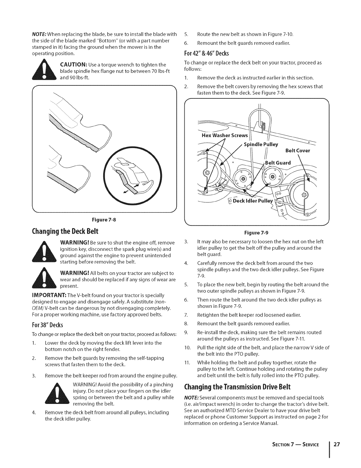
NOTE:When replacing the blade, be sure to install the blade with
the side of the blade marked "Bottom" (or with a part number
stamped in it) facing the ground when the mower is in the
operating position.
i_ CAUTION: Usea torque wrench to tighten the
blade spindle hex flange nut to between 70 Ibs-ft
and 90 Ibs-ft.
(
Changing
Figure 7-8
the DeckBelt
WARNING! Besure to shut the engine off, remove
ignition key, disconnect the spark plug wire(s) and
ground against the engine to prevent unintended
starting before removing the belt.
WARNING! All belts on your tractor are subject to
wear and should be replaced if any signs of wear are
present.
IMPORTANT: The V-belt found on your tractor is specially
designed to engage and disengage safely. A substitute (non-
OEM)V-belt can be dangerous by not disengaging completely.
For a proper working machine, use factory approved belts.
For38" Decks
Tochange or replacethe deck belt on your tractor, proceed asfollows:
1. Lower the deck by moving the deck lift lever into the
bottom notch on the right fender.
2. Remove the belt guards by removing the self-tapping
screws that fasten them to the deck.
3. Remove the belt keeper rod from around the engine pulley.
WARNING!Avoid the possibility of a pinching
injury. Do not place your fingers on the idler
spring or between the belt and a pulley while
removing the belt.
4. Remove the deck belt from around all pulleys, including
the deck idler pulley.
S. Route the new belt as shown in Figure 7-10.
6. Remount the belt guards removed earlier.
For42"& 46"Decks
To change or replace the deck belt on your tractor, proceed as
follows:
1. Remove the deck as instructed earlier in this section.
2. Remove the belt covers by removing the hex screws that
fasten them to the deck. See Figure 7-9.
f
Spindle Pulley
Belt Cover
,Belt Guard
Figure 7-9
3. It may also be necessary to loosen the hex nut on the left
idler pulley to get the belt off the pulley and around the
belt guard.
4. Carefully remove the deck belt from around the two
spindle pulleys and the two deck idler pulleys. See Figure
7-9.
5. To place the new belt, begin by routing the belt around the
two outer spindle pulleys as shown in Figure 7-9.
6. Then route the belt around the two deck idler pulleys as
shown in Figure 7-9.
7. Retighten the belt keeper rod loosened earlier.
8. Remount the belt guards removed earlier.
9. Re-install the deck, making sure the belt remains routed
around the pulleys as instructed. See Figure 7-11.
10. Pull the right side of the belt, and place the narrowV side of
the belt into the PTOpulley.
11. While holding the belt and pulley together, rotate the
pulley to the left. Continue holding and rotating the pulley
and belt until the belt isfully rolled into the PTOpulley.
Changingthe TransmissionDriveBelt
NOTE: Several components must be removed and special tools
(i.e. air/impact wrench) in order to change the tractor's drive belt.
See an authorized MTD Service Dealer to have your drive belt
replaced or phone Customer Support as instructed on page 2 for
information on ordering a Service Manual.
SECTION7 -- SERVICE 27
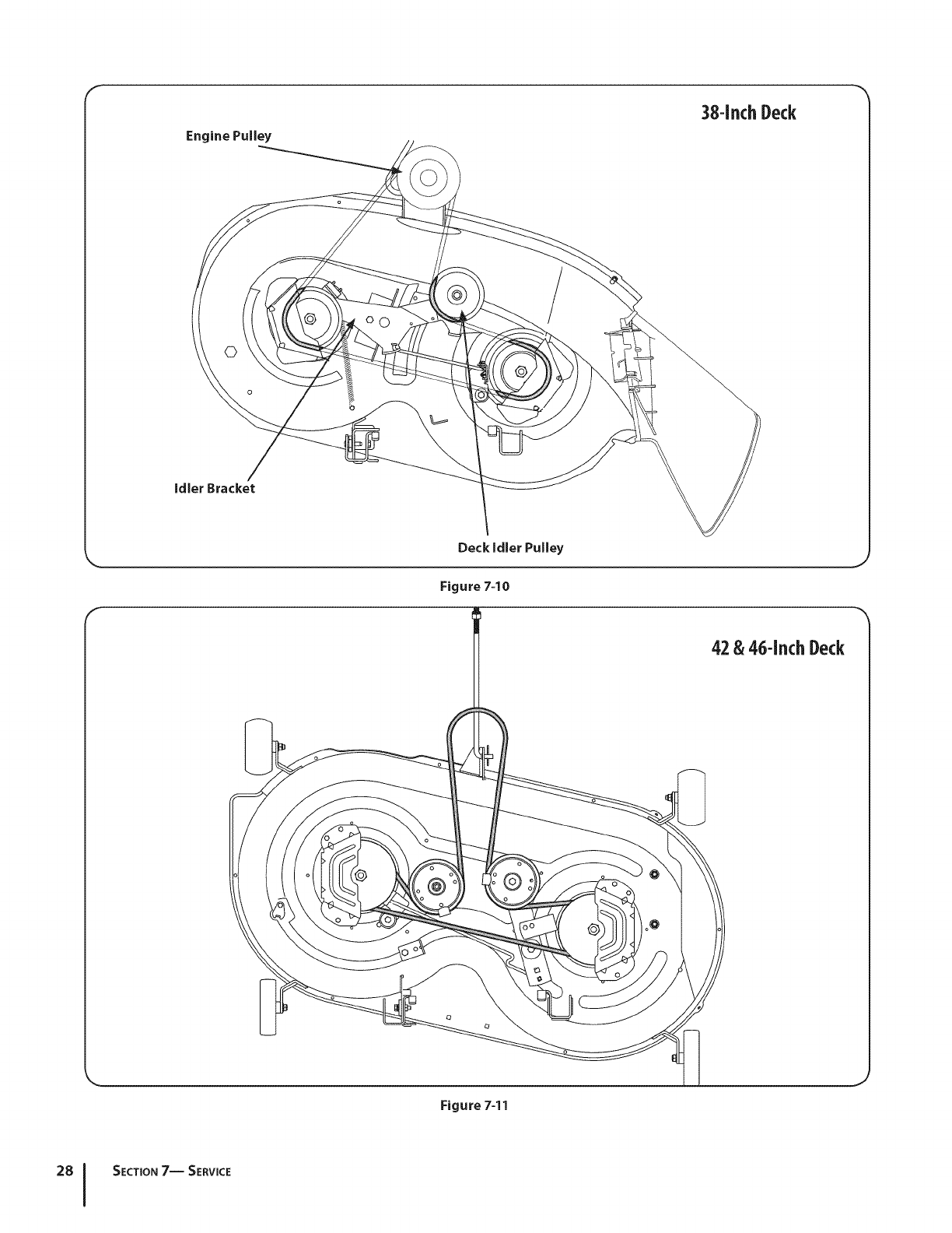
F
38-inchDeck
©
Figure 7=11
SECTION7-- SERVICE
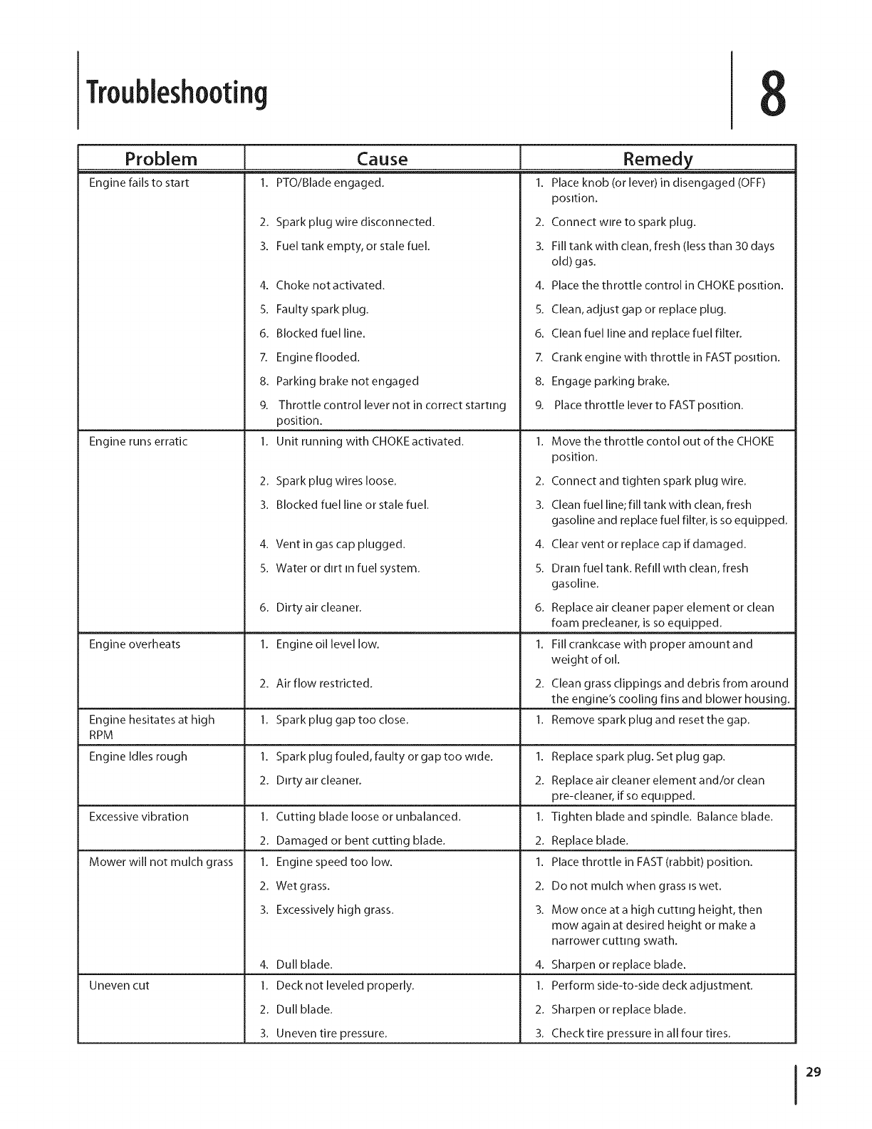
Troubleshooting
Problem
Engine fails to start
Cause
PTO/Blade engaged.
Engine runs erratic
Engine overheats
2. Spark plug wire disconnected.
3. Fuel tank empty, or stale fuel.
4. Choke not activated.
S. Faulty spark plug.
6. Blocked fuel line.
7. Engine flooded.
8. Parking brake not engaged
Remedy
1. Place knob (or lever)in disengaged (OFF)
position.
2. Connect wire to spark plug.
3. Fill tank with clean, fresh (less than 30 days
old) gas.
g. Throttle control lever not in correct starting
position.
1. Unit running with CHOKE activated.
4. Place the throttle control in CHOKE position.
5. Clean, adjust gap or replace plug.
6. Clean fuel line and replace fuel filter.
7. Crank engine with throttle in FAST position.
8. Engage parking brake.
Engine hesitates at high
RPM
Engine Idles rough
Excessive vibration
Mower will not mulch grass
Uneven cut
2. Spark plug wires loose.
3. Blocked fuel line or stale fuel.
4. Ventin gas cap plugged.
5. Water or dtrt in fuel system.
6. Dirty air cleaner.
1. Engine oil level low.
2. Air flow restricted.
1. Spark plug gap too close.
1. Spark plug fouled, faulty or gap too wide.
2. Dirty air cleaner.
1. Cutting blade loose or unbalanced.
2. Damaged or bent cutting blade.
1. Engine speed too low.
2. Wet grass.
3. Excessively high grass.
4. Dull blade.
1. Deck not leveled properly.
2. Dull blade.
3. Uneven tire pressure.
9. Place throttle lever to FAST position.
1. Move the throttle contol out of the CHOKE
position.
2. Connect and tighten spark plug wire.
3. Clean fuel line; fill tank with clean, fresh
gasoline and replace fuel filter, is so equipped.
4. Clear vent or replace cap if damaged.
5. Dram fuel tank. Refill with clean, fresh
gasoline.
6. Replace air cleaner paper element or clean
foam precleaner, is so equipped.
1. Fill crankcase with proper amount and
weight of oil.
2. Clean grass clippings and debris from around
the engine's cooling fins and blower housing.
1. Remove spark plug and resetthe gap.
1. Replace spark plug. Set plug gap.
2. Replace air cleaner element and/or clean
pre-cleaner, if so equipped.
1. Tighten blade and spindle. Balance blade.
2. Replace blade.
1. Place throttle in FAST (rabbit) position.
2. Do not mulch when grass is wet.
3. Mowonceata high cutting height, then
mow again at desired height or make a
narrower cutting swath.
4. Sharpen or replace blade.
1. Perform side-to-side deck adjustment.
2. Sharpen or replace blade.
3. Checktire pressure in all four tires.
29

ReplacementParts
DriveBelt (MowingDeck)38" Deck 954-04062
DriveBelt (MowingDeck)42" Deck 954-04060B
DriveBelt (MowingDeck)46" Deck 954-04219
DeckBlade(38" Deck) 942-0610A
DeckBlade(42" Deck) 942-04308
ExtremeDeckBlade(42" Deck) 942-04308-X
DeckBlade(46" Deck) 942-04290
ExtremeDeckBlade(46" Deck) 942-04290-X
DeckSpindle(38"Deck) 918-04474A
DeckSpindle(42"Deck) 918-04822A
DeckSpindle(46"Deck) 918-04636A
DeckWheel(Rear) 734-0973
DeckWheel(Front- 42"& 46"Deck) 734-04155
Battery 925-1707D
Tire (Front)15x 6 x 6 RoundShoulder 734-04240A
Tire (Front)15x 6 x 6 SquareShoulder 734-1731
Tire (Rear)20 x 8 x 8 RoundShoulder 734-04241
Tire (Rear)20 x 8 x 8 SquareShoulder 734-1730
HubCap 931-0484A
FuelTankCap 951-12179A
FuelTankCap(CAmodels& unitswithCarbonCannisters) 951-12426
ThrottleControl/ChokeCable(SingleCylinderEngines) 746-04367
DischargeChuteAssembly38" Deck 931-1032B
DischargeChuteAssembly42" Deck 631-04288
DischargeChuteAssembly46" Deck 631-04288
Key 925-1745A
9
NOTE:This Operators Manual covers a range of product specifications for various models. Characteristics and features discussed and/
or illustrated in this manual may not be applicable to all models. MTD LLC reserves the right to change product specifications, designs
and equipment without notice and without incurring obligation.
NOTE: Download a complete Parts Manual free of charge at www.mtdproducts.com or phone (800) 800-7310 to purchase a Parts
Manual. Be sure to have your model number and serial number ready. These can be found on the model plate located under the seat.
Refer to page 2 for more information regarding locating your model and serial numbers.

Attachments&Accessories 1
The followingattachmentsandaccessoriesarecompatiblefor thesemodelsof LawnTractors.Seethe retailerfromwhichyou purchased
yourtractor,anauthorizedMTDServiceDealeror phone(800)800-7310for informationregardingpriceandavailability.
i_ CAUTION: Thesemodelsof LawnTractorsare NOTdesignedfor usewithanytype of ground-engagingattachments(e.g.
tilleror plow).Useof thistypeof equipmentWILLvoidthe tractor'swarranty.
19A30006OEM 42-inchDeckMulchKit
490-850-0005 CuttingBladeRemovalTool
OEM-190-679 Bumper
OEM-190-180 DoubleBaggerKit 38"
490-900-0025 DeckWashKit
490-290-0013 ArnoldTractorCover
SPW-134 ArnoldSparkPlugWrench
490-325-L019 24 OzTire &TubeSealantByTireAid
490-850-L014 Tire AidDeluxeTire PlugKit By TireAid
490-328-L017 16"TractorTubeWith SealantByTire Aid
_to
22216 32oz.STA-BIL®
31

11

FEDERALand/or CALIFORNIAEMISSIONCONTROLWARRANTYSTATEMENT
YOURWARRANTYRIGHTSANDOBLIGATIONS
MTD Consumer Group Inc, the United States Environmental Protection Agency (EPA), and, for those products certified for sale in the state of
California, the California Air Resources Board (CARB) are pleased to explain the emission (evaporative and/or exhaust) control system (ECS)
warranty on your outdoor 2006 and later small off-road spark-ignited engine and equipment (outdoor equipment engine) In California, new
outdoor equipment engines must be designed, built and equipped to meet the State's stringent anti-smog standards (in other states, 1997 and
later model year equipment must be designed, built, and equipped to meet the U.S. EPA small off-road, spark ignition engine regulations. MTD
Consumer Group Inc must warrant the ECSon your outdoor equipment engine for the period of time listed below provided there has been no
abuse, neglect or improper maintenance of outdoor equipment engine.
Your ECS may include parts such as the carburetor, fuel-injection system, the ignition system, catalytic converter, fuel tanks, fuel lines, fuel caps,
valves, canisters, filters, vapor hoses, clamps, connectors, and other associated emission-related components.
Where a warrantable condition exists, MTD Consumer Group Inc will repair your outdoor equipment engine at no cost to you including
diagnosis, parts and labor.
MANUFACTURER'SWARRANTYCOVERAGE:
This emission control system is warranted for two years. If any emission-related part on your outdoor equipment engine is defective, the part
will be repaired or replaced by MTD CONSUMER GROUP INC.
OWNER'SWARRANTYRESPONSIBILITIES:
As the outdoor equipment engine owner, you are responsible for performance of the required maintenance listed in your owner's manual. MTD
Consumer Group Inc recommends that you retain all receipts covering maintenance on your outdoor equipment engine, but MTD Consumer
Group Inc cannot deny warranty solely for the lack of receipts.
As the outdoor equipment engine owner, you should however be aware that MTD Consumer Group Inc may deny you warranty coverage if
your outdoor equipment engine or a part has failed due to abuse, neglect, or improper maintenance or unapproved modifications.
You are responsible for presenting your outdoor equipment engine to MTD Consumer Group Inc's distribution center or service center as soon
as the problem exists. The warranty repairs should be completed in a reasonable amount of time, not to exceed 30 days. If you have a question
regarding your warranty coverage, you should contact the MTD Consumer Group Inc Service Department at 1-800-800-7310 or via email at
http://su pport.mtd prod ucts.com
GENERALEMISSIONSWARRANTYCOVERAGE:
MTD Consumer Group Inc warrants to the ultimate purchaser and each subsequent purchaser that the outdoor equipment engine is: Designed,
built and equipped so as to conform with all applicable regulations; and free from defects in materials and workmanship that cause the failure
of a warranted part to be identical in all material respects to that part as described in MTD Consumer Group Inc's application for certification.
The warranty period begins on the date the outdoor equipment engine is delivered to an ultimate purchaser or first placed into service. The
warranty period is two years.
Subject to certain conditions and exclusions as stated below, the warranty on emission-related parts is as follows:
1. Any warranted part that is not scheduled for replacement as required maintenance in the written instructions supplied, is warranted for
the warranty period stated above. If the part fails during the period of warranty coverage, the part will be repaired or replaced by MTD
Consumer Group Inc according to subsection (4) below. Any such part repaired or replaced under warranty will be warranted for the
remainder of the period.
2. Any warranted part that is scheduled only for regular inspection in the written instructions supplied is warranted for the warranty period
stated above. Any such part repaired or replaced under warranty will be warranted for the remaining warranty period.
3. Any warranted part that is scheduled for replacement as required maintenance in the written instructions supplied is warranted for the
period of time before the first scheduled replacement date for that part. If the part fails before the first scheduled replacement, the part
will be repaired or replaced by MTD Consumer Group Inc according to subsection (4) below. Any such part repaired or replaced under
warranty will be warranted for the remainder of the period prior to the first scheduled replacement point for the part.
Repair or replacement of any warranted part under the warranty provisions herein must be performed at a warranty station at no charge
to the owner.
4.
5. Notwithstanding the provisions herein, warranty services or repairs will be provided at all of our distribution centers that are franchised to
service the subject engines or equipment.
6. The outdoor equipment engine owner will not be charged for diagnostic labor that is directly associated with diagnosis of a defective,
emission-related warranted part, provided that such diagnostic work is performed at a warranty station.
7. MTD Consumer Group Inc is liable for damages to other engine or equipment components proximately caused by a failure under
warranty of any warranted part.
8. Throughout the off-road engine and equipment warranty period stated above, MTD Consumer Group Inc will maintain a supply of
warranted parts sufficient to meet the expected demand for such parts.
9. Any replacement part may be used in the performance of any warranty maintenance or repairs and must be provided without charge to
the owner. Such use will not reduce the warranty obligations of MTD Consumer Group Inc.

10. Add-onormodifiedpartsthatarenotexemptedbytheAirResourcesBoardmaynotbeused.Theuseofanynon-exemptedadd-onor
modifiedpartsbytheultimatepurchaserwillbegroundsfordisallowingawarrantyclaims.MTDConsumerGroupIncwillnotbeliableto
warrantfailuresofwarrantedpartscausedbytheuseofanon-exemptedadd-onormodifiedpart.
WARRANTEDPARTS:
The repair or replacement of any warranted part otherwise eligible for warranty coverage may be excluded from such warranty coverage if
MTD Consumer Group Inc demonstrates that the outdoor equipment engine has been abused, neglected, or improperly maintained, and that
such abuse, neglect, or improper maintenance was the direct cause of the need for repair or replacement of the part. That notwithstanding,
any adjustment of a component that has a factory installed, and properly operating, adjustment limiting device is still eligible for warranty
coverage. Further, the coverage under this warranty extends only to parts that were present on the off-road engine and equipment purchased.
The following emission warranty parts are covered (if applicable):
1. Fuel Metering System
Cold start enrichment system (soft choke)
Carburetor and internal parts (or fuel injection system)
Fuel pump
Fuel tank
2. Air Induction System
Air cleaner
Intake manifold
3. Ignition System
Spark plug(s)
Magneto ignition system
4. Exhaust System
Catalytic converter
SAI (Reed valve)
5. Miscellaneous Items Used in Above System
Vacuum, temperature, position, time sensitive valves and switches
Connectors and assemblies
6. Evaporative Control
Fuel hose
Fuel hose clamps
Tethered fuel cap
Carbon canister
• Vapor lines
GDOCq00223Rev.A

MANUFACTURER'S LiMiTED WARRANTY FOR
The limited warranty set forth below is given by MTD LLC with
respect to new merchandise purchased and used in the United
States and/or its territories and possessions, and by MTD Products
Limited with respect to new merchandise purchased and used
in Canada and/or its territories and possessions (either entity
respectively, "MTD").
This warranty is in addition to any applicable emissions warranty
provided with your product.
"MTD" warrants this product (excluding its Normal WearParts and
Attachments as described below) against defects in material and
workmanship for a period of two (2) years commencing on the date
of original purchase and will, at its option, repair or replace, free of
charge, any part found to be defective in materials or workmanship.
This limited warranty shall only apply if this product has been
operated and maintained in accordance with the Operator's Manual
furnished with the product, and has not been subject to misuse,
abuse, commercial use, neglect, accident, improper maintenance,
alteration, vandalism, theft, fire, water, or damage because of other
peril or natural disaster. Damage resulting from the installation or
use of any part, accessory or attachment not approved by MTD
for use with the product(s) covered by this manual will void your
warranty as to any resulting damage.
Normal WearParts are warranted to be free from defects in material
and workmanship for a period of thirty (30) days from the date of
purchase. Normal wear parts include, but are not limited to items
such as: batteries, belts, blades, blade adapters, tines, grass bags,
wheels, rider deck wheels, seats, snow thrower skid shoes, friction
wheels, shave plates, auger spiral rubber and tires.
Attachments -- MTD warrants attachments for this product against
defects in material and workmanship for a period of one (1) year,
commencing on the date of the attachment's original purchase or
lease. Attachments include, but are not limited to items such as:
grass collectors and mulch kits.
HOW TO OBTAIN SERVICE: Warranty service is available, WITH
PROOF OF PURCHASE, through your local authorized service dealer.
To locate the dealer in your area:
In the U.S.A.
Check your Yellow Pages, or contact MTD LLC at P.O. Box 361131,
Cleveland, Ohio 44136-0019, or call 1-800-800-7310, 1-330-220-
4683 or log on to our Web site at www.mtdproducts.com.
In Canada
Contact MTD Products Limited, Kitchener, ON N2G 4J1, or call
1-800-668-1238 or log on to our Web site at www.mtdcanada.com.
This limited warranty does not provide coverage in the following
cases:
a. The engine or component parts thereof. These items may
carry a separate manufacturer's warranty. Refer to applicable
manufacturer's warranty for terms and conditions.
b. Log splitter pumps, valves, and cylinders have a separate
one- year warranty.
c. Routine maintenance items such as lubricants, filters, blade
sharpening, tune-ups, brake adjustments, clutch adjustments,
deck adjustments, and normal deterioration of the exterior
finish due to use or exposure.
d. Service completed by someone other than an authorized
service dealer.
e. MTD does not extend any warranty for products sold or
exported outside of the United States and/or Canada, and
their respective possessions and territories, except those sold
through MTD's authorized channels of export distribution.
f. Replacement parts that are not genuine MTD parts.
g. Transportation charges and service calls.
h. MTD does not warrant this product for commercial use.
No implied warranty, including any implied warranty of
merchantability or fitness for a particular purpose, applies
after the applicable period of express written warranty above
as to the parts as identified. No other express warranty,
whether written or oral, except as mentioned above, given
by any person or entity, including adealer or retailer, with
respect to any product, shall bind MTD. During the period of
the warranty, the exclusive remedy is repair or replacement of
the product as set forth above.
The provisions as set forth in this warranty provide the sole
and exclusive remedy arising from the sale. MTD shall not
be liable for incidental or consequential loss or damage
including, without limitation, expenses incurred for substitute
or replacement lawn care services or for rental expenses to
temporarily replace a warranted product.
Some states do not allow the exclusion or limitation of incidental
or consequential damages, or limitations on how long an implied
warranty lasts, so the above exclusions or limitations may not apply
to you.
In no event shall recovery of any kind be greater than the amount
of the purchase price of the product sold. Alteration of safety
features of the product shall void this warranty. You assume the
risk and liability for loss, damage, or injury to you and your property
and/or to others and their property arising out of the misuse or
inability to use the product.
This limited warranty shall not extend to anyone other than the
original purchaser or to the person for whom it was purchased as a
gift.
HOW STATE LAW RELATES TO THIS WARRANTY: This limited
warranty gives you specific legal rights, and you may also have
other rights which vary from state to state.
IMPORTANT: Owner must present Original Proof of Purchase to
obtain warranty coverage.
MTD LLC, P.O. BOX 361131 CLEVELAND, OHIO 44136-0019; Phone: 1-800-800-7310, 1-330-220-4683
MTD Canada Limited - KITCHENER, ON N2G 4J1; Phone 1-800-668-1238
GDOC-IO0015REV,B
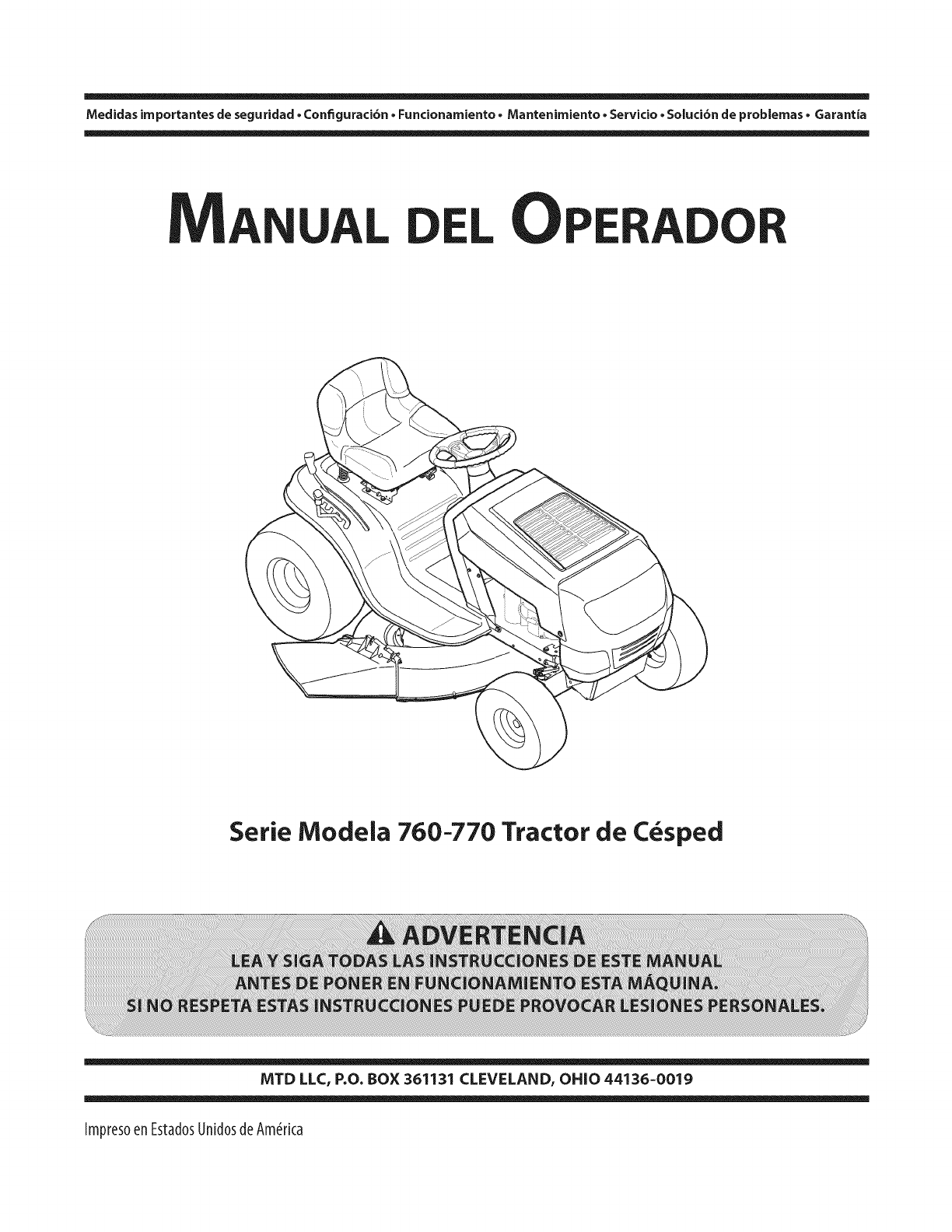
Medidas importantes de seguridad • Configuraci6n • Funcionamiento • Mantenimiento • Servicio • Soluci6n de problemas • Garantia
MANUAL DELOPERADOR
Serie Moclela 760-770 Tractor de C_specl
MTD LLC, P.O. BOX 361131 CLEVELAND, OHiO 44136=0019
ImpresoenEstadosUnidosdeAmerica
A!propietario 1
Gracias
Gracias por comprar un tractor corta c_sped fabricado pot
MTD. El mismo ha sido diseffado cuidadosamente para brindar
excelente rendimiento si se Io opera y mantiene correctamente.
Pot favor lea todo este manual antes de operar el equipo.
Le indica c6mo configurar, operar y mantener la m_quina
con seguridad y f_cilmente. Pot favor asegurese de seguir
cuidadosamente yen todo momento las pr_cticas de seguridad
recomendadas y de hac_rselas seguir a cualquier otra persona
que opere la m_quina. En caso de no hacerlo podrfan producirse
lesiones personales o daffos materiales.
Toda la informaci6n contenida en este manual hace referencia
a la m_s reciente informaci6n de producto disponible en el
momento de la impresi6n. Revise el manual frecuentemente
para familiarizarse con la m_quina, sus caracterfsticas y
funcionamiento. Por favor tenga en cuenta que este Manual
del Operador puede cubrir una gama de especificaciones de
productos de diferentes modelos. Las caracteristicas y funciones
incluidas y/o ilustradas en este manual pueden no set aplicables
a todos los modelos. MTD se reserva el derecho de modificar las
especificaciones de los productos, los dise_os y el equipo sin
previo aviso y sin generar responsabilidad pot obligaciones de
ningun tipo.
Si procede, la informaci6n de las pruebas de potencia utilizado
para establecer la potencia nominal del motor equipado en esta
m_quina se puede encontrar en www.opei.org o en el sitio web
del fabricante del motor.
Si tiene algun problema o duda respecto a la m_quina, Ilame a
su distribuidor de servicio local MTD autorizado o p6ngase en
contacto directamente con nosotros. Los numeros de tel6fono,
direcci6n del sitio web y direcci6n postal de la Asistencia al
Cliente de MTD se encuentran en esta p_gina. Queremos
garantizar su entera satisfacci6n en todo momento.
En este manual, las referencias al lado derecho oizquierdo de la
m_quina se observan desde la posici6n del operador.
El fabricante del motor es el responsable de todas las
cuestiones relacionadas con el rendimiento, potencia de salida,
especificaciones, garantia y mantenimiento del motor. Para
obtener mayor informaci6n consulte el Manual del Propietario /
Operador entregado por el fabricante del motor, que se envia, en
un paquete pot separado, junto con su m_quina.
indite
Medidas importantes de seguridad .................... 38
Montaje y Conf_guraci6n ...................................... 44
Controles y Caractefisticas ................................... 47
Funcionamiento .................................................... 50
Mantenimiento yAjustes ...................................... 54
Servicio ................................................................... 58
Soluci6n de problemas ......................................... 63
Piezas de reemplazo ............................................. 64
Aditamentos yaccesofios ..................................... 65
6arantia ................................................................. 68
Registro de informaci6ndeproducto
Antes de configurar y operar su equipo nuevo, pot favor Iocalice
la placa del modelo en el equipo y registre la informaci6n en el
_rea situada a la derecha. Puede Iocalizar la placa de modelo
mirando debajo del asiento. Si tiene que solicitar soporte t6cnico
a trav6s de nuestro sitio web, el Departamento de Asistencia
al Cliente, o de un distribuidor de servicio autorizado local,
necesitar_ esta informaci6n.
_OMERO
DD
NOMERO
DD
DE MODELO
[3[3[3[3[3[3[3[3[3
DE SERIE
DNDNDNDND
Asistenciaal Ciiente
En caso de tener problemas para montar este producto o de tener dudas con respecto a los controles, funcionamiento
o mantenimiento de esta m_quina, puede solidtar la ayuda de expertos. Elija entre las opdones que se presentan a
continuad6n:
0 Visite nuestro sitio web en www.mtdproducts.com
Vet Videos demostrativos de instalad6n de mantenimiento y piezas en www.mtdparts.com/KnowledgeCenter
0 Llame al representante de Atend6n al Cliente al (800) 800-7310 o (330) 220-4683
0 Escribanos a MTD LLC •P.O.Box 361131 •Cleveland, OH •44136-0019
37
Medidasimportantes de seguridad 2
ADVERTENCIA" La presencia de este sfmbolo indica que se trata de instrucciones
importantes de seguridad que se deben respetar para evitar poner en peligro su seguridad
personal y/o material y la de otras personas. Lea y siga todas las instrucciones de este manual
antes de poner en fundonamiento esta mgquina. Si no respeta estas instrucciones puede
provocar lesiones personales. Cuando vea este s[mbolo, iTENGA EN CUENTAS LAS
ADVERTENCIAS!
PROPOSICION 65 DE CALIFORNIA
_DVERTENCIA: El escape del motor de este producto, algunos de sus componentes y
algunos componentes del veh[culo contienen o liberan sustancias qu[micas que el estado
de California considera que pueden producir cSncer, defectos de nacimiento u otros
problemas reproductivos.
_DVERTENCIA: Los bornes de la bateria y los accesorios afines contienen plomo y compuestos
de plomo, sustancias quimicas que segun Io establecido por el Estado de California causan
c_ncer y da_os en el sistema reproductivo. Ldvese las manos despu_s de estar en contacto con estos
componentes. J
dl_i_ PELIGRO: Esta mgquina est_ dise_ada para set utilizada respetando las normas de
seguridad contenidas en este manual. AI igual que con cualquier tipo de equipo motorizado,
un descuido o error pot parte del operador puede producir lesiones graves. Esta m_quina es
capaz de amputar manos y pies y de arrojar objetos con gran fuerza. De no respetar las
instrucciones de seguridad siguientes se pueden producir lesiones graves o la muerte.
Fundonamientogeneral
2_
3_
Lea, entienda y cumpla todas las instrucciones incluidas en
la m_quina yen los manuales antes de montarla y utilizarla.
Guarde este manual en un lugar seguro para consultas
futuras y peri6dicas, asi como para solicitar repuestos.
Familiaricese con todos los controles y con el uso adecuado
de los mismos. Sepa c6mo detener la m_quina y desactivar
los controles r_pidamente.
No permita nunca que los ni_os menores de 14 ahos
utilicen esta m_quina. Los ni_os de 14 ahos en adelante
deben leery entender las instrucciones de operaci6n y
normas de seguridad contenidas en este manual, y en la
m_quina y deben set entrenados y supervisados pot un
adulto.
4_
5.
Nunca permita que los adultos operen esta m_quina sin
recibir antes la instruccidn apropiada.
Para ayudar a evitar el contacto con las cuchillas o una
lesi6n por algOn objeto que sea arrojado, mantenga a los
observadores, a los ayudantes, ni_os y mascotas alejados
al menos 25 metros de la m_quina mientras est_ en
funcionamiento. Detenga la m_quina si alguien entra en la
zona.
6. Inspeccione minuciosamente el _rea donde utilizar_ el
equipo. Retire todas las piedras, palos, cables, huesos,
juguetes y otros objetos extrahos que podrian set
recogidos y arrojados pot la acci6n de las cuchillas. Los
objetos arrojados pot la m_quina pueden producir lesiones
graves.
7. Planifique el patr6n de corte del c_sped que ha de seguir
para evitar la descarga de material hacia los caminos, las
veredas, los observadores, etc. Evite adem_s descargar
material contra las paredes y obstrucciones que podrian
provocar que el material descargado rebote contra el
operador.
8. Para protegerse los ojos utilice siempre anteojos o
antiparras de seguridad mientras opera la m_quina o
mientras la ajusta o repara. Los objetos arrojados que
rebotan pueden producir lesiones oculares graves.
9. Utilice zapatos de trabajo resistentes, de suela fuerte,
asi como pantalones y camisas ajustados. Las prendas
sueltas o las alhajas pueden quedar atrapadas en las
piezas movibles. Nunca opere la m_quina descalzo o con
sandalias.
10. Est_atentoalacortadorayaladirecci6ndeladescarga
delosaditamentosynoapunteanadie.Nuncaoperela
cortadoradec_spedsinqueest_nensulugarapropiadola
cubiertadedescargaoelcolectorderecortesdec_sped.
11. Nopongalasmanosolospiescercadelaspiezasrotatorias
odebajodelaplataformadecorte.Elcontactoconlas
cuchillaspuedeproducirlaamputaci6ndemanosypies.
12. Unacubiertadedescargafaltanteodaffadapuedeprovocar
elcontactoconlacuchillaolesionespotobjetosarrojados.
13. Detengala(s)cuchilla(s)cuandoatraviesesenderos,sendaso
caminosdegravaycuandonoest_cortandoelc(_sped.
14. Vigileeltr_nsitovehicularcuandoest_operandocercadeo
encrucesdecaminos.Estam_quinanodebeutilizarseenla
viapublica.
15. Noopereestam_quinabajolosefectosdelalcoholode
drogas.
16. Corteelc_spedsolamenteconluzdediaoconunabuena
luzartificial.
17. Nuncatransportepasajeros.
18. Desenganchela(s)cuchilla(s)antesdecolocarlamarchaatr_s.
Retrocedalentamente.Siempremirehaciaabajoyhaciaatr_s
antesymientrasretrocede,paraevitaraccidentes.
19. Reduzcalavelocidadantesdedarlavuelta.Operela
m_quinasuavemente.Evitelaoperaci6nerr_ticayla
velocidadexcesiva.
20. Desenganchela(s)cuchilla(s),coloqueelfrenode
estacionamiento,detengaelmotoryesperehastaquela(s)
cuchilla(s)sedetenga(n)potcompletoantesderetirarel
colectordec_sped,vaciarlosrecortes,destaparelcanal,
retirarrestosdec_spedodesechos,ohacercualquierajuste.
21. Nuncadejelam_quinaenfuncionamientosinvigilancia.
Apaguesiemprelascuchillas,coloquelatransmisi6nen
neutral,coloqueelfrenodemano,detengaelmotoryretire
laIlaveantesdebajarsedelvehiculo.
22. Tengasumocuidadoalcargarodescargarlam&quinaen
unremolqueocami6n.Estaunidadnodebeconducirse
enascensoodescensoderampas,porquepodrialadearse
yprovocarlesionespersonalesgraves.Enlasrampasla
m_quinasedebeempujarmanualmenteparacargarlao
descargarlacorrectamente.
23. Elsilenciadoryelmotorsecalientanypuedencausar
quemaduras.Nolostoque.
24. Reviseelespaciolibrepotencimadelacabezaantes
deconducirbajolasramasbajasde_rboles,cables,
cerramientosdepuertas,etc.enloscualeseloperador
podriaatorarseosetempujadofueradelam_quina,Ioque
podriaresultarenlesionesgraves.
25. Desenganchetodoslosembraguesdelosaccesorios,
presionetotalmenteelpedaldelfrenoycambieaneutral
antesdeintentararrancarelmotor.
26. Lam&quinaest&diseffadaparacortarc_spedresidencial
normal,conunaalturanomayora10".Nointentecortar
c_speddemasiadocrecido,seco(potej.,pastura)nipilas
dehojassecas.Elc_spedylashojassecaspuedenentrar
encontactoconelescapedelmotory/oacumularseenla
plataformadelacortadoradec_sped,convirti_ndoseenun
peligrodeincendio
27. Utilicesolamenteaccesoriosyaditamentosaprobadospara
estam_quinapotelfabricantedelamisma.Lea,comprenda
ysigatodaslasinstruccionesproporcionadasconlos
accesoriosoaditamentosaprobados.
28. Losdatos estadisticos muestran que los operadores de 60
afrosy mayores seven involucrados en un alto porcentaje
de lesiones relacionadas con tractores corta c_sped. Estos
operadores deben evaluar su capacidad para operar el
tractor corta c_sped en forma suficientemente segura para
protegerse a ellos mismos y a los demos contra lesiones
graves.
29. Sise presentan situaciones que no est_n previstas en este
manual, seacuidadoso y use el sentido comOn. Sinecesita
ayuda, p6ngase en contacto con su representante de
asistencia al cliente.
Fundonamiento en pendientes
Las pendientes son un factor importante relacionado con
accidentes pot derrape y vuelcos que pueden producir lesiones
graves e incluso la muerte. La operaci6n en pendientes requiere
mayor precauci6n. Si no puede retroceder en la pendiente o si no
se siente seguro, no realice ninguna operaci6n de corte.
Para su seguridad, use el indicador de pendientes que se incluye
como parte de este manual para medir la pendiente antes de
operar la m_quina en una zona inclinada. Si la pendiente es
mayor de 15 grados segOn el medidor, no opere esta m_quina en
ese sector, pues podria causar lesiones graves.
Hagal0siguiente:
1. Pode hacia arriba y abajo de las pendientes, no de forma
transversal. Tenga cuidado cuando cambie de direcci6n al
operar en pendiente.
2. Est_ atento a los hoyos, surcos, baches, rocas, u otros objetos
ocultos. El terreno desnivelado puede voltear la m_quina. El
c_sped alto puede ocultar obst_culos.
3. Vaya a baja velocidad. Elija una velocidad Io suficientemente
baja, de modo que no tenga que detenerse o hacer cambios
mientras est_ sobre la pendiente. Los neum_ticos podrian
perder tracci6n sobre las pendientes aun cuando los
frenos funcionaran apropiadamente. Siempre mantenga la
m_quina en cambio mientras desciende las pendientes, para
poder frenar con el motor.
4. Siga las recomendaciones del fabricante para los pesos o
contrapesos de las ruedas, para mejorar la estabilidad de la
m_quina.
5. Tenga especial cuidado con los colectores de c_sped u otros
aditamentos. Los mismos pueden modificar la estabilidad de
la m_quina.
6. Haga que todos los movimientos en las pendientes sean
lentos y graduales. No cambie repentinamente la velocidad
ni la direcci6n. Un frenado o cambio de velocidad repentinos
pueden causar que el frente de la m_quina se levante y d_
una voltereta hacia atr_s, Io que podria producir lesiones
graves.
7. Evite arrancar o detenerse en una pendiente. Si los
neum_ticos pierden la tracci6n, desenganche las cuchillas y
descienda lentamente la pendiente.
No haga I0siguiente:
I. No gire sobre las pendientes a menos que sea necesario. Si es
posible, gire lentamente y gradualmente durante el descenso.
2. No corte el c_sped cerca de pozos, hundimientos o
terraplenes. La cortadora de c_sped puede volcarse
repentinamente si una de las ruedas est_ sobre el borde de un
acantilado, zanja o si un borde se desmorona.
3. No intente estabilizar la m_quina poniendo el pie en el suelo.
4. No utilice un colector de c_sped en pendientes empinadas.
5. No pode el c_sped humedo. Una menor tracci6n podria
causar derrapes.
SECTION 2 -- JV_EDIDAS IMPORTANTES DE SEGURIDAD 39
6. No cambie a transmisi6n neutral para descender. El exceso de
velocidad puede hacer que el operador pierda el control de la
m_iquina, ocasionando lesiones graves e incluso la muerte.
7. No remolque cargas pesadas detr_is de los aditamentos
(carrito de basura cargado, podadora de rodillos, etc) en
pendientes mayores de 5 grados. Cuando se desplaza
pendiente abajo, el peso adicional tiende a empujar el
tractor y puede hacer que se pierda el control del mismo (pot
ejemplo, el tractor se puede acelerar, se reduce la capacidad
para frenar y maniobrar, los accesorios pueden plegarse como
un cortaplumas y hacer que el tractor vuelque).
Ni_0s
1. Pueden ocurrir accidentes tr_igicos si el operador no
est,1 atento a la presencia de ni_os. Por Io general, los
ni_os se sienten atraidos por este tipo de m_iquinas y su
funcionamiento. No entienden los riesgos ni los peligros.
Nunca asuma que los ni_os permanecer_in en el mismo lugar
donde los vio por ultima vez.
a. Mantenga a los ni_os fuera del &rea de trabajo y bajo
estricta vigilancia de un adulto responsable adem_is
del propio operador.
b. Est_ alerta y apague la m_iquina si un ni_o ingresa al
_irea.
c. Antes y mientras est,1 retrocediendo, mire hacia atr_is
y cuide que no haya ni_os.
d. Nunca transporte ni_os, aOn con la cuchilla apagada.
Podrian caerse y resultar severamente heridos o
interferir con la operaci6n segura de la m_iquina.
e. Tenga extrema precauci6n cuando se aproxime a
esquinas ciegas, portales, arbustos, _irboles u otros
objetos que puedan impedirle ver a un ni_o que se
cruce en el recorrido de la m_iquina.
f. Para evitar accidentes al operar en marcha arras,
siempre clesenganche las cuchillas antes de
colocar marcha atrbs. Si est_ instalaclo, el "Modo
Precaucibn Marcha Atrbs" no debe utilizarse
cuando hay ni_os u otras personas presentes.
g. Mantenga a los ni_os alejados de los motores en
marcha o calientes. Pueden sufrir quemaduras con un
silenciador caliente.
h. Retire la Ilave cuando deje la m_iquina sin vigilancia,
evite que una persona sin autorizaci6n la maneje.
2. No permita nunca que los ni_os menores de 14 ahos utilicen
esta m_iquina. Los ni_os de 14 ahos en adelante deben
leery entender las instrucciones de operacidn y normas de
seguridad contenidas en este manual, yen la m_iquina y
deben ser entrenados y supervisados pot un adulto.
Rem01que
1. Remolque Onicamente con una m_iquma que cuente con
un enganche dise_ado para remolcar. No acople equipo
remolcado excepto en el punto de enganche.
2. Siga las recomendaciones del fabricante en Io que respecta
a los limites de peso de los equipos a remolcar y al
remolque en pendientes.
3. Nunca permita la presencia de ni_os u otras personas
dentro o sobre los equipos remolcados.
4. En las pendientes, el peso del equipo remolcado puede
causar p_rdida de tracci6n y p_rdida de control de la
m_iquina.
5. Despl_icese lentamente y deje distancia adicional para
frenado.
6. No cambie a transmisi6n neutral para descender.
Servicio
Manej0segur0 de la gas01ina:
1. Para evitar lesiones personales o dahos materiales sea
sumamente cuidadoso al manipular la gasolina. La
gasolina es sumamente inflamable ysus vapores
pueclen causar e×plosiones. Se puede lesionar
gravemente si derrama gasolina sobre usted o sobre la
ropa, ya que _sta se puede incendiar. Livese la piel y
c_imbiese de ropa de inmediato.
a. Utilice s61o los recipientes para gasolina autorizados.
b. Nunca Ilene los recipientes en el interior de
un vehiculo o cami6n o caja de remolque con
recubrimiento pl_istico. Coloque siempre los
recipientes en el piso y lejos del vehiculo antes de
realizar la carga.
c. Cuando sea factible, retire el equipo a gasolina del
cami6n o remolque y II_nelo en el suelo. Si esto
no es posible, Ilene el equipo en un remolque con
un contenedor port_itil, en vez de hacerlo con una
boquilla dispensadora de gasolina.
d. Mantenga la boquilla de Ilenado en contacto con el
borde del dep6sito de combustible o con la abertura
del recipiente en todo momento, hasta terminar
la carga. No utilice un dispositivo de boquilla de
apertura/cierre.
e. Apague todos los cigarrillos, cigarros, pipas y otras
fuentes de combusti6n.
fi Nunca cargue combustible en la m_iquina en un
espacio cerrado.
g. Nunca saque la tapa del combustible ni agregue
combustible mientras el motor est,1 caliente o en
marcha. Deje que el motor se enfrie por Io menos
dos minutos antes de volver a cargar combustible.
h. Nunca Ilene en exceso el dep6sito de combustible.
Llene el tanque no m_is de 1/2pulgada pot debajo
de la base del cuello del tap6n de carga, para dejar
espacio para la expansi6n del combustible.
i. Vuelva a colocar la tapa de la gasolina y ajOstela
bien.
j. Limpie el combustible que se haya derramado sobre
el motor y el equipo. Traslade la m_iquina a otra
zona. Espere 5 minutos antes de encender el motor.
k. Para reducir el riesgo de incendio, mantenga la
m_iquina limpia de pasto, hojas y de acumulaci6n
de otros residuos. Limpie los derrames de aceite o
combustible y saque todos los residuos embebidos
de combustible.
I. Nunca guarde la m_iquina o el recipiente de
combustible en un espacio cerrado donde haya
fuego, chispas o luz piloto, como por ejemplo de
calentadores de agua, calefactores de ambientes,
hornos, secadores de ropa u otros aparatos a gas.
m. Deje que la m_iquina se enfrie cinco minutos pot Io
menos antes de guardarla.
Servid0 general
1. Nunca encienda el motor en espacios cerrados o en una
zona con poca ventilaci6n. El escape del motor contiene
mon6xido de carbono, un gas inodoro y letal.
SECTION 2 -- _V_EDIDAS IMPORTANTES DE SEGURIDAD
2. Antes de limpiar, reparar o inspeccionar la m_iquina,
compruebe que la(s) cuchilla(s) y todas las partes en
movimiento se hayan detenido. Desconecte el cable de la
bujia y p6ngalo haciendo masa contra el motor para evitar
que se encienda accidentalmente.
3. Revise peri6dicamente para asegurarse que las cuchillas
se detengan pot completo en aproximadamente cinco (5)
segundos despu_s de accionar el control de desenganche
de la(s) cuchilla(s). Si las cuchillas no se detienen dentro de
este lapso de tiempo, su unidad deber_i ser reparada por su
distribuidor de servicio autorizado MTD.
4. Revise con frecuencia el funcionamiento del sistema de
frenos ya que est_i sujeto a desgaste pot la operaci6n
normal. Ajuste y efectue mantenimiento segun se requiera.
5. Revise los pernos de montaje de la(s) cuchilla(s) y del
motor a intervalos frecuentes para verificar que est_n
bien apretados. Adem_is, inspeccione visualmente la(s)
cuchilla(s) en busca de dahos (por ejemplo, desgaste
excesivo, abolladuras, rajaduras, etc.). Reemplace la(s)
cuchilla(s) unicamente con las cuchillas de fabricantes de
equipos originales (O.E.M.) listadas en este manual. "El
uso de piezas que no cumplen con las especificaciones
del equipo original podria tenet como resultado un
rendimiento incorrecto y adem_is poner en riesgo la
seguridad".
6. Las cuchillas de las podadoras son muy afiladas. Envuelva
la cuchilla o utilice guantes y extreme las precauciones
cuando efectue mantenimiento.
7. Mantenga todos los pernos, tuercas y tornillos bien
ajustados para asegurarse de que la m_iquina se encuentra
en condiciones seguras de operaci6n.
8. Nunca altere el sistema de enclavamiento de seguridad ni
otros mecanismos de seguridad. Controle peri6dicamente
que funcionen correctamente.
9. Despu_s de golpear con algun objeto extra,o, detenga el
motor, desconecte el cable de la bujia y conecte el motor a
masa. Inspeccione minuciosamente la m_iquina para vet si
est_i da_ada. Repare el daho antes de arrancar y utilizar la
m_iquina.
10. Nunca trate de hacer ajustes o reparaciones a la m_iquina
mientras el motor est_i en marcha.
11. Los componentes del colector de c_sped y la cubierta de
descarga, est_in sujetos a desgaste y da_os que podrian
dejar expuestas partes en movimiento o permitir que se
arrojen objetos. Para proteger su seguridad, verifique
frecuentemente todos los componentes y reempl_icelos
inmediatamente s61o con piezas de los fabricantes del
equipo original, listados en este manual. "El uso de piezas
que no cumplen con las especificaciones del equipo
original podria tener como resultado un rendimiento
incorrecto y adem_is poner en riesgo la seguridad".
12. No cambie la configuraci6n del regulador del motor ni Io
opere a sobrevelocidad. El regulador del motor controla la
velocidad m_ixima segura de funcionamiento del motor.
13. Mantenga o reemplace las etiquetas de seguridad e
instrucciones segun sea necesario.
14. Respete las normas referentes a la disposici6n correcta y las
reglamentaciones sobre gasolina, aceite, etc. para proteger
el medio ambiente.
15. Segun la Comisi6n de Seguridad de Productos para el
Consumidor de los Estados Unidos (CPSC) y la Agencia
de Protecci6n Ambiental de los Estados Unidos (EPA),
este producto tiene una vide dtJlmedia de siete (7) ahos,
6270 horas de funcionamiento. AI finalizar la vide dtJl
media, adquiera una m_iquina nueva o haga inspeccionar
anualmente 6sta por un distribuidor de servicio autorizado
para cerciorarse de que todos los sistemas mec_inicos y de
seguridad funcionan correctamente y no tienen excesivo
desgaste. Si no Io hace, pueden producirse accidentes,
lesiones o muerte.
Nomodifique el motor
Para evitar lesiones graves o la muerte, no modifique el motor
bajo ninguna circunstancia. Si cambia la configuracidn del
regulador del motor el motor puede descontrolarse y operar a
velocidades inseguras. Nunca cambie la configuraci6n de f_ibrica
del regulador del motor.
Avisoreferidoa emisiones
Los motores que est_i n certificados y cumplen con las
regulaciones de emisiones federales EPA y de California para
SORE (Equipos peque_os todo terreno) est_in certificados para
operar con gasolina comOn sin plomo y pueden incluir los
siguientes sistemas de control de emisiones: Modificaci6n de
motor (EM) y catalizador de tres vias (TWC) si est_in equipados de
esa manera.
Guardachispas
ADVERTENCIA: Esta m_iquina est,1 equipada con
un motor de combusti6n interna y no debe ser
utilizada en un terreno agreste cubierto por bosque,
malezas o hierba ni cerca del mismo excepto que el
sistema de escape del motor est_ equipado con un
amortiguador de chispas que cumpla con las leyes
locales o estatales correspondientes (si las hay).
Si se utiliza un amortiguador de chispas el operador Io debe
mantener en condiciones de uso adecuadas. En el Estado
de California las medidas anteriormente mencionadas son
exigidas por ley (Articulo 4442 del C6digo de Recursos Publicos
de California). Es posible que existan leyes similares en otros
estados. Las leyes federales se aplican en territorios federales.
Puede conseguir el amortiguador de chispas para el silenciador
a trav_s de su distribuidor de mantenimiento de motores
autorizado m_is cercano o poni_ndose en contacto con el
departamento de servicios, Apartado Postal 361131 Cleveland,
Ohio 44136-0019.
ADVERTENCIA: Su responsabilidad--Restrinja el uso de esta m_iquina motorizada alas personas que lean,
comprendan y respeten las advertencias e instrucciones que figuran en este manual yen la m_iquina.
GUARDEESTASINSTRUCCIONES
SECTION 2 -- _V_EDIDAS IMPORTANTES DE SEGURIDAD 41
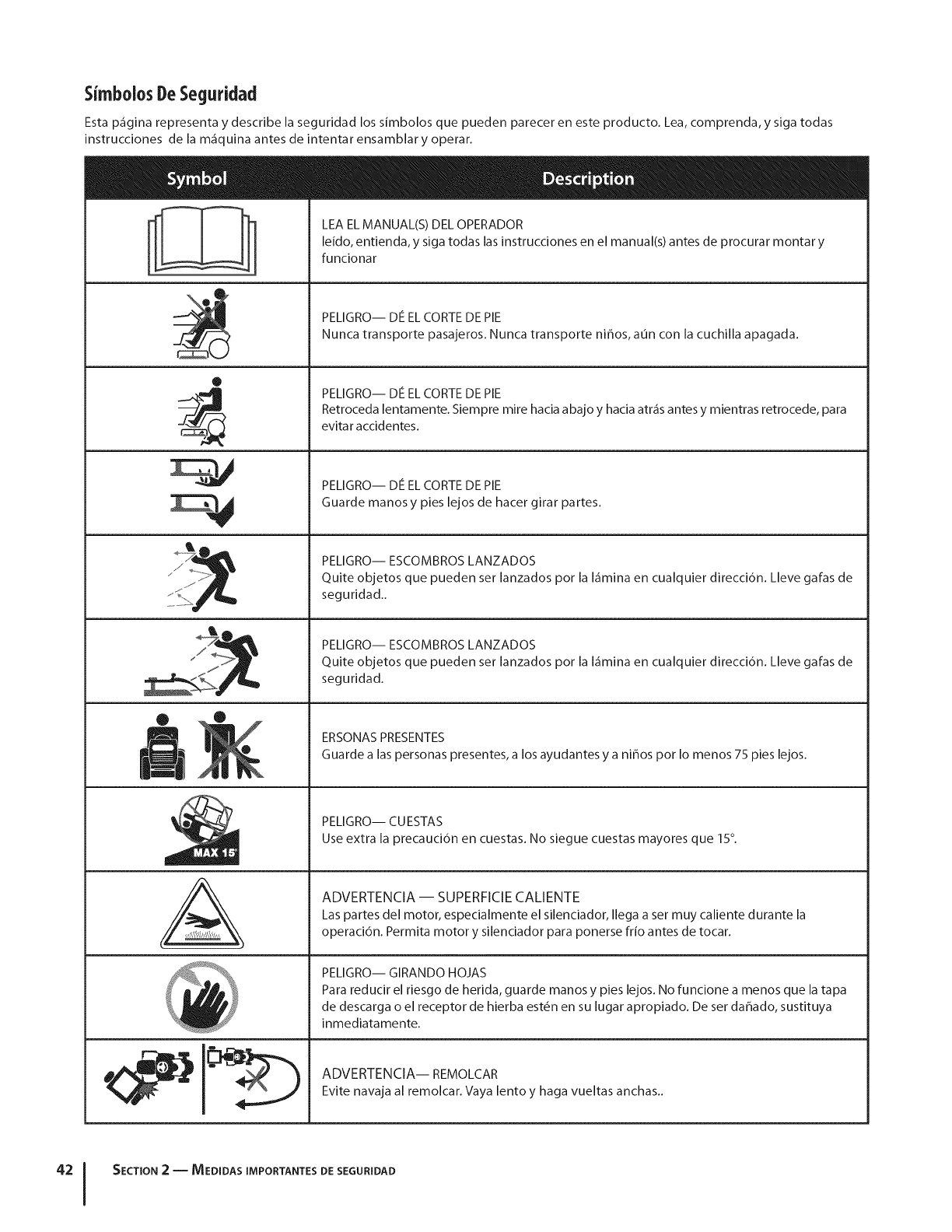
SimbolosDeSeguridad
Esta p_gina representa y describe la seguridad los simbolos que pueden parecer en este producto. Lea, comprenda, y siga todas
instrucciones de la m_quina antes de intentar ensamblar y operar.
0
J
Lq
M
N
A
LEA EL MANUAL(S) DEL OPERADOR
leido, entienda, y siga todas las instrucciones en el manual(s) antes de procurar montar y
funcionar
PELIGRO-- DE EL CORTE DE PIE
Nunca transporte pasajeros. Nunca transporte niffos, aun con la cuchilla apagada.
PELIGRO-- DE EL CORTE DE PIE
Retroceda lentamente. Siempre mire hacia abajo y hacia atr_s antes y mientras retrocede, para
evita r a ccidentes.
PELIGRO-- DE EL CORTE DE PIE
Guarde manos y pies lejos de hacer girar partes.
PELIGRO-- ESCOMBROS LANZADOS
Quite objetos que pueden set lanzados pot la I_mina en cualquier direcci6n. Lleve gafas de
seguridad..
PELIGRO-- ESCOMBROS LANZADOS
Quite objetos que pueden set lanzados pot la I_mina en cualquier direcci6n. Lleve gafas de
seguridad.
ERSONAS PRESENTES
Guarde a las personas presentes, a los ayudantes y a niffos pot Io menos 75 pies lejos.
PELIGRO-- CUESTAS
Use extra la precauci6n en cuestas. No siegue cuestas mayores que 15°.
ADVERTENCIA -- SUPERFICIE CALIENTE
Las partes del motor, especialmente el silenciador, Ilega a set muy caliente durante la
operaci6n. Permita motor y silenciador para ponerse fr[o antes de tocar.
PELIGRO-- GIRANDO HOJAS
Para reducir el riesgo de herida, guarde manos y pies lejos. No funcione a menos que la tapa
de descarga o el receptor de hierba est_n en su lugar apropiado. De ser daffado, sustituya
inmediatamente.
ADVERTENCIA-- REMOLCAR
Evite navaja al remolcar. Vaya lento y haga vueltas anchas..
SECTION 2 -- MEDIDAS IMPORTANTES DE SEGURIDAD
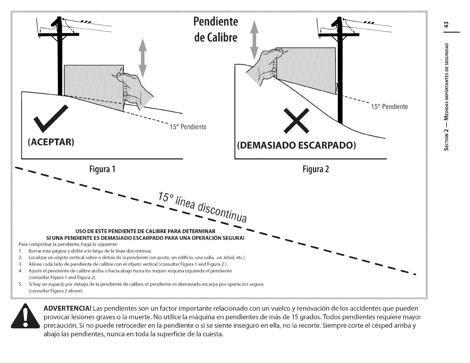
(ACEPTAR)
15° Pendiente
(DEMASIADO ESCARPADO)
15° Pendiente
FiguraI
""-
USO DE ESTE PENDIENTE DE CALIBRE PARA DETERMINAR
SI UNA PENDHENTE ES DEMASIADO ESCARPADO PARA UNA OPERACI6N SEGURA!
Para comprobar la pendiente, haga Io siguiente:
1. Borrar esta p_igina y doble a Io largo de la linea discontinua.
2. Localizar un objeto vertical sobre o detr_is de la pendiente (un poste, un edificio, una valla, un _irbol, etc.)
3. Alinee cada lado de pendiente de calibre con el objeto vertical (consultar Figura 1 and Figura 2 ).
4. Ajuste el pendiente de calibre arriba o hacia abajo hasta los toques esquina izquierda el pendiente
(consultar Figura 1 and Figura 2).
5. Si hay un espacio pot debajo de la pendiente de calibre, el pendiente es demasiado escarpa pot operaci6n segura
(consultar Figura 2 above).
Figura2
}
ADVERTENCIA! Las pendientes son un factor importante relacionado con un vuelco y renovaci6n de los accidentes que pueden
provocar lesiones graves o la muerte. No utilice la m_quina en pendientes de m&s de 15 grados. Todos pendientes requiere mayor
precauci6n. Si no puede retroceder en la pendiente o si se siente inseguro en ella, no la recorte. Siempre corte el c_sped arriba y
abajo las pendientes, nunca en toda la superficie de la cuesta.
g3
F-
Z
2
,I
I
z
o
I=
M3
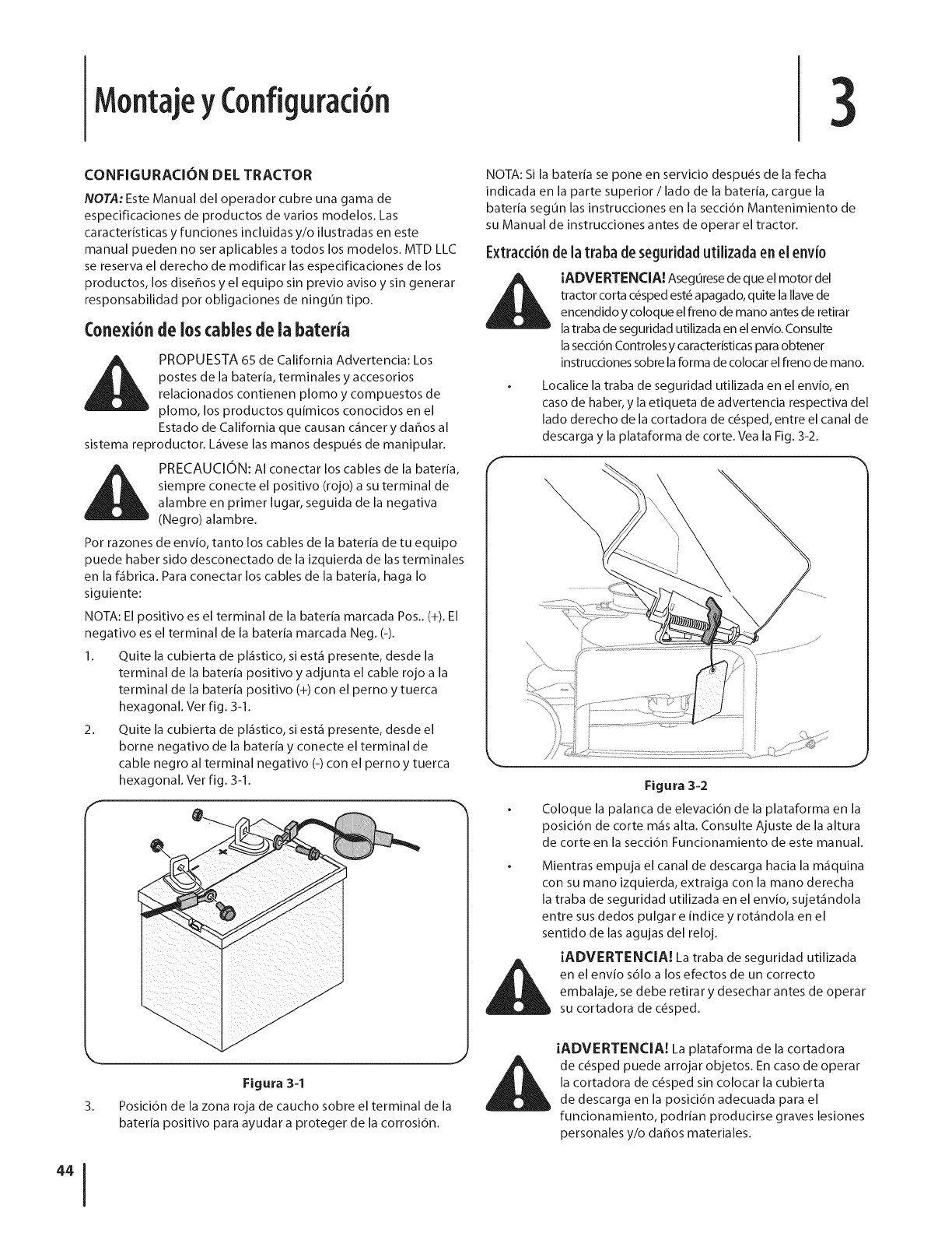
MontajeyConfiguraci6n 3
CONFIGURACION DEL TRACTOR
NOTA: Este Manual del operador cubre una gama de
especificaciones de productos de varios modelos. Las
caracteristicas y funciones incluidas y/o ilustradas en este
manual pueden no ser aplicables a todos los modelos. MTD LLC
se reserva el derecho de modificar las especificaciones de los
productos, los diseffos y el equipo sin previo aviso y sin generar
responsabilidad por obligaciones de ning0n tipo.
Conexi6nde loscablesdeia bateria
PROPUESTA 65 de California Advertencia: Los
postes de la bateria, terminales y accesorios
relacionados contienen plomo y compuestos de
plomo, los productos quimicos conocidos en el
Estado de California que causan c_incer y daffos al
sistema reproductor. Uivese las manos despu_s de manipular.
PRECAUCION: AI conectar los cables de la bateria,
siempre conecte el positivo (rojo) a su terminal de
alambre en primer lugar, seguida de la negativa
(Negro) alambre.
Por razones de envio, tanto los cables de la bateria de tu equipo
puede haber sido desconectado de la izquierda de las terminales
en la f_ibrica. Para conectar los cables de la bateria, haga Io
siguiente:
NOTA: El positivo es el terminal de la bateria marcada Pos.. (+). El
negativo es el terminal de la bateria marcada Neg. (-).
1. Quite la cubierta de pl_stico, si est_ presente, desde la
terminal de la bateria positivo y adjunta el cable rojo a la
terminal de la bateria positivo (+) con el perno y tuerca
hexagonal. Vet fig. 3-1.
2. Quite la cubierta de pl_stico, si est_ presente, desde el
borne negativo de la bateria y conecte el terminal de
cable negro al terminal negativo (-) con el perno y tuerca
hexagonal. Vet fig. 3-1.
Figura 3=1
3. Posici6n de la zona roja de caucho sobre el terminal de la
bateria positivo para ayudar a proteger de la corrosi6n.
NOTA: Si la bateria se pone en servicio despu_s de la fecha
indicada en la parte superior /lado de la bateria, cargue la
bateria segun las instrucciones en la secci6n Mantenimiento de
su Manual de instrucciones antes de operar el tractor.
Extracd6n dela traba deseguridad utilizada en el env[o
iADVERTENCIA! Asegurese de que el motor del
tractor corta c_sped est_ apagado, quite la Ilave de
encendido y coloque el freno de mano antes de retirar
la traba de seguridad utilizada en el envio. Consulte
la secci6n Controlesy caracterBticas para obtener
instrucciones sobre la forma de colocar el freno de mano.
Localice la traba de seguridad utilizada en el envio, en
caso de haber, y la etiqueta de advertencia respectiva del
lado derecho de la cortadora de c_sped, entre el canal de
descarga y la plataforma de corte. Vea la Fig. 3-2.
\
Figura 3=2
Coloque la palanca de elevaci6n de la plataforma en la
posici6n de corte m_isalta. Consulte Ajuste de la altura
de corte en la secci6n Funcionamiento de este manual.
Mientras empuja el canal de descarga hacia la m_quina
con su mano izquierda, extraiga con la mano derecha
la traba de seguridad utilizada en el envio, sujet_ndola
entre sus dedos pulgar e [ndice y rot_ndola en el
sentido de las agujas del reloj.
iADVERTENCIA! La traba de seguridad utilizada
en el envio s61o a los efectos de un correcto
embalaje, se debe retirar y desechar antes de operar
su cortadora de c_sped.
iADVERTENCIA! La plataforma de la cortadora
de c_sped puede arrojar objetos. En caso de operar
la cortadora de c_sped sin colocar la cubierta
de descarga en la posici6n adecuada para el
funcionamiento, podrian producirse graves lesiones
personales y/o daffos materiales.
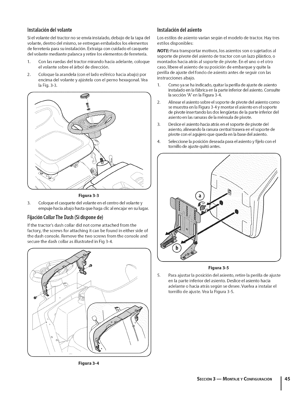
Instalad6n delvolante
Si el volante del tractor no se envia instalado, debajo de la tapa del
volante, dentro del mismo, se entregan embalados los elementos
de ferreteria para su instalaci6n. Extraiga con cuidado el casquete
del volante mediante palanca y retire los elementos de ferreteria.
1. Con las ruedas del tractor mirando hacia adelante, coloque
el volante sobre el _rbol de direcci6n.
2. Coloque la arandela (con el lado esf_rico hacia abajo) pot
encima del volante y ajustela con el perno hexagonal. Vea
la Fig. 3-3.
Instalad6n del asient0
Los estilos de asiento var{an segun el modelo de tractor. Hay tres
estilos disponibles:
NOTE: Para transportar motivos, los asientos son o sujetados al
soporte de pivote del asiento de tractor con un lazo pl_stico, o
montados hacia atr_s al soporte de pivote. En el uno o el otro
caso, libere el asiento de su posici6n de embarque y quite la
perilla de ajuste del rondo de asiento antes de seguir con las
instrucciones abajo.
1. Como ya se ha indicado, quitar la perilla de ajuste de asiento
instalado en la f_brica en la parte inferior del asiento. Consulte
la secci6n "A" en la Figura 3-4.
2. Alinear el asiento sobre el soporte de pivote del asiento como
se muestra en la Figura 3-4 y montar el asiento en el soporte
de pivote insertando las dos leng0etas de la parte inferior del
asiento en las ranuras de la m6nsula de pivote.
3. Deslice el asiento hacia atr_s en el soporte de pivote del
asiento, alineando la ranura central trasera en el soporte de
pivote con el agujero que queda en la base del asiento.
4. Seleccione la posici6n deseada para el asiento y fijelo con el
tornillo de ajuste quit6 antes.
Figura 3-3
3. Coloque el casquete del volante en el centro del volante y
empuje hacia abajo hasta que haga clic al encajar en su lugar.
FUad6nCollarThe Dash(Sidispone de)
If the tractor's dash collar did not come attached from the
factory, the screws for attaching it can be found in either side of
the dash console. Remove the two screws from the console and
secure the dash collar as illustrated in Fig 3-4.
®
\
\
Figura 3-4
5.
Figura 3-5
Para ajustar la posici6n del asiento, retire la perilla de ajuste
en la parte inferior del asiento. Deslice el asiento hacia
adelante o hacia atr_s seg0n se desee. Vuelva a instalar el
tornillo de ajuste. Vea la Figura 3-5.
SECCION3 -- MONTAJE Y CONFIGURACI(SN 45
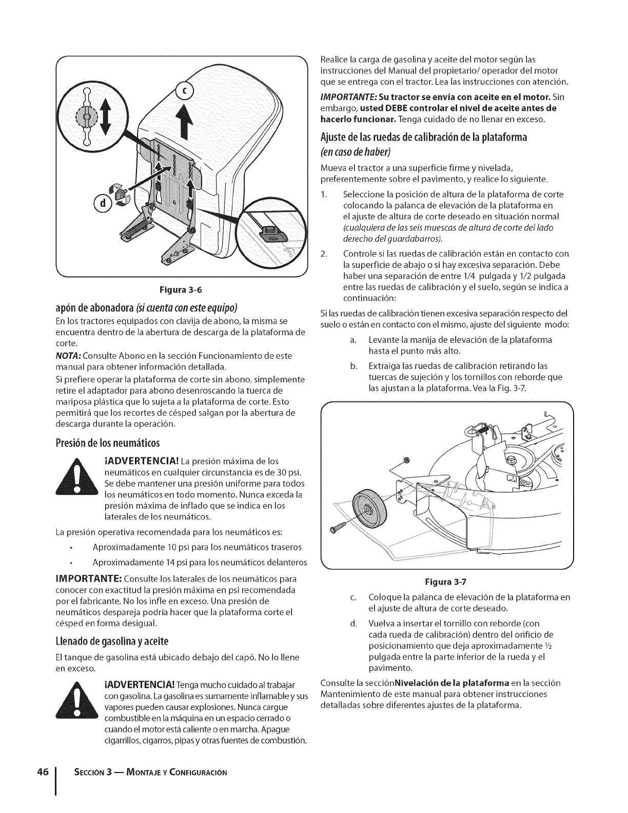
Figura 3-6
ap6n de abonadora (sicuenta conesteequipo)
En los tractores equipados con clavija de abono, la misma se
encuentra dentro de la abertura de descarga de la plataforma de
corte.
NOTA: Consulte Abono en la secci6n Funcionamiento de este
manual para obtener informaci6n detallada.
Si prefiere operar la plataforma de corte sin abono, simplemente
retire el adaptador para abono desenroscando la tuerca de
mariposa pl_stica que Io sujeta a la plataforma de corte. Esto
permitir_ que los recortes de c_sped salgan pot la abertura de
descarga durante la operaci6n.
Presi6nde 10sneum_tk0s
iADVERTENCIA! La presidn m_xima de los
neum_ticos en cualquier circunstancia es de 30 psi.
Sedebe mantener una presidn uniforme para todos
los neum_ticos en todo momento. Nunca exceda la
presidn m_xima de inflado que se indica en los
laterales de los neum_ticos.
La presi6n operativa recomendada para los neum_ticos es:
Aproximadamente 10 psi para los neum_ticos traseros
Aproximadamente 14 psi para los neum_ticos delanteros
IMPORTANTE: Consulte los laterales de los neum_ticos para
conocer con exactitud la presidn m_xima en psi recomendada
por el fabricante. No los infle en exceso. Una presidn de
neum_ticos despareja podria hacer que la plataforma corte el
c_sped en forma desigual.
Uenad0 de gas0iinayaceite
El tanque de gasolina est_ ubicado debajo del cap6. No Io Ilene
en exceso.
!
iADVERTENCIA. Tenga mucho cuidado al trabajar
con gasolina. La gasolina es sumamente inflamable y sus
vapores pueden causar explosiones. Nunca cargue
combustible en la m_quina en un espacio cerrado o
cuando el motor est_ caliente o en marcha. Apague
cigarrillos, cigarros, pipas y otras fuentes de combusti6n.
Realice la carga de gasolina y aceite del motor segun las
instrucciones del Manual del propietario/operador del motor
que se entrega con el tractor. Lea las instrucciones con atenci6n.
IMPORTANTE: Su tractor se envia con aceite en el motor. Sin
embargo, usted DEBE controlar el nivel de aceite antes de
hacerlo funcionar. Tenga cuidado de no Ilenar en exceso.
Ajustedelas ruedas decalibrad6nde la plataf0rma
(en caso de haber)
Mueva el tractor a una superficie firme y nivelada,
preferentemente sobre el pavimento, y realice Io siguiente.
1. Seleccione la posicidn de altura de la plataforma de corte
colocando la palanca de elevacidn de la plataforma en
el ajuste de altura de corte deseado en situacidn normal
(cualquiera de las seis muescas de altura de torte del lado
derecho del guardabarros).
2. Controle si las ruedas de calibracidn est_n en contacto con
la superficie de abajo o si hay excesiva separaci6n. Debe
haber una separaci6n de entre 1/4 pulgada y 1/2 pulgada
entre las ruedas de calibraci6n y el suelo, segOn se indica a
continuacidn:
Si las ruedas de calibracidn tienen excesiva separacidn respecto del
suelo o est_n en contacto con el mismo, ajuste del siguiente modo:
a. Levante la manija de elevacidn de la plataforma
hasta el punto m_s alto.
b. Extraiga las ruedas de calibracidn retirando las
tuercas de sujecidn y los tornillos con reborde que
las ajustan a la plataforma. Vea la Fig. 3-7.
Figura 3-7
c. Coloque la palanca de elevaci6n de la plataforma en
el ajuste de altura de corte deseado.
d. Vuelva a insertar el tornillo con reborde (con
cada rueda de calibraci6n) dentro del orificio de
posicionamiento que deja aproximadamente 1/2
pulgada entre la parte inferior de la rueda y el
pavimento.
Consulte la secci6nNivelaci6n de la plataforma en la secci6n
Mantenimiento de este manual para obtener instrucciones
detalladas sobre diferentes ajustes de la plataforma.
SECCION3 -- MONTAJE Y CONFIGURACION
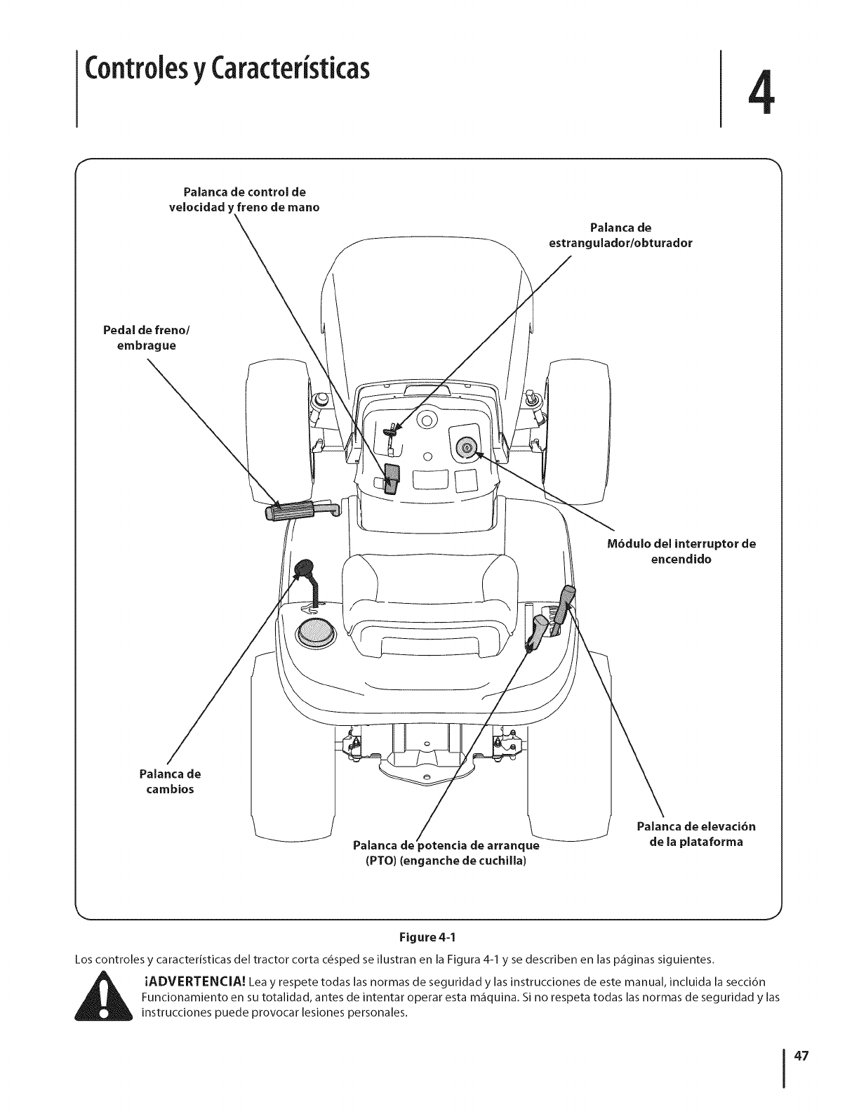
ControlesyCaracter sticas 4
Paianca de control de
velocidad y freno de mano
Palanca de
estrangulador/obturador
Pedal de freno/
embrague
M6dulo del interruptor de
encendido
Palanca de
cambios
Palanca de _otencia de arranque
(PTO) (enganche de cuchilla)
Palanca de elevaci6n
de la plataforma
Figure 4=1
Los controles y caracteristicas del tractor corta c_sped se ilustran en la Figura 4-1 y se describen en las p_ginas siguientes.
i_ iADVERTENCIA! Lea y respete todas las normas de seguridad y las instrucciones de este manual, incluida la secci6n
Funcionamiento en su totalidad, antes de intentar operar esta m_quina. Si no respeta todas las normas de seguridad y las
instrucciones puede provocar lesiones personales.
47
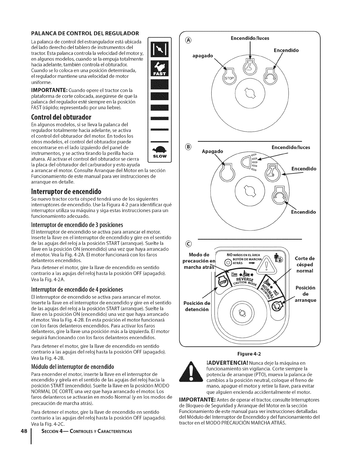
PALANCA DE CONTROL DEL REGULADOR
La palanca de control del estrangulador est_ ubicada Ii_
del lado derecho del tablero de instrumentos del
tractor. Esta palanca controla la velocidad del motor y,
en algunos modelos, cuando se la empuja totalmente
hacia adelante, tambi_n controla el obturador.
Cuando se Io coloca en una posici6n determinada,
el regulador mantiene una velocidad de motor
uniforme.
IMPORTANTE: Cuando opere el tractor con la
plataforma de corte colocada, asegurese de que la
palanca del regulador est_ siempre en la posici6n
FAST (r_pido; representado por una liebre).
Controldei obturador
En algunos modelos, si se Ileva la palanca del
regulador totalmente hacia adelante, se activa
el control del obturador del motor. En todos los
otros modelos, el control del obturador puede
encontrarse en el lado izquierdo del panel de
instrumentos, y se activa tirando la perilla hacia slow
afuera. AI activar el control del obturador se cierra
la placa del obturador del carburador y esto ayuda
a arrancar el motor. Consulte Arranque del Motor en la secci6n
Funcionamiento de este manual para ver instrucciones de
arranque en detalle.
Interruptor de encendido
Su nuevo tractor corta c_sped tendr_ uno de los siguientes
interruptores de encendido. Use la Figura 4-2 para identificar qu_
interruptor utiliza su m_quina y siga estas instrucciones para un
funcionamiento adecuado.
Interruptor de encendido de3 posidones
El interruptor de encendido se activa para arrancar el motor.
Inserte la Ilave en el interruptor de encendido y gire en el sentido
de las agujas del reloj a la posicidn START (arranque). Suelte la
Ilave en la posicidn ON (encendido) una vez que haya arrancado
el motor. Yea la Fig. 4-2A. El motor funcionar_ con los faros
delanteros encendidos.
Para detener el motor, gire la Ilave de encendido en sentido
contrario alas agujas del reloj hasta la posici6n OFF (apagado).
Vea la Fig. 4-2A.
Interruptor de encendido de4 posidones
El interruptor de encendido se activa para arrancar el motor.
Inserte la Ilave en el interruptor de encendido y gire en el sentido
de las agujas del reloj a la posicidn START (arranque). Suelte la
Ilave en la posicidn ON (encendido) una vez que haya arrancado
el motor. Vea la Fig. 4-2B. En esta posicidn el motor funcionar_
con los faros delanteros encendidos. Para activar los faros
delanteros, gire la Ilave una posicidn m_s a la izquierda. El motor
seguir_ funcionando con los faros delanteros encendidos.
Para detener el motor, gire la Ilave de encendido en sentido
contrario a las agujas del reloj hasta la posicidn OFF (apagado).
Vea la Fig. 4-2B.
M6dulo del interruptorde encendido
Para encender el motor, inserte la Ilave en el interruptor de
encendido y girela en el sentido de las agujas del reloj hacia la
posicidn START (encendido). Suelte la Ilave en la posicidn MODO
NORMAL DE CORTE una vez que haya arrancado el motor. Los
faros delanteros se activar_n en modo Normal (y en los modos de
precaucidn de marcha atr_s).
Para detener el motor, gire la Ilave de encendido en sentido
contrario alas agujas del reloj hasta la posici6n OFF (apagado).
Vea la Fig. 4-2C.
48 I SECCION 4-- CONTROLES Y CARACTERiSTICAS
I
apagado
Encendido/luces
Encendido
®Apagado Encendido/luces
Encendido
Corte de
c_sped
normal
Posici6n de
detenci6n
Posici6n
de
arranque
Figure 4=2
iADVERTENCIA! Nunca deje la m_quina en
funcionamiento sin vigilancia. Corte siempre la
potencia de arranque (PTO),mueva la palanca de
cambios a la posici6n neutral, coloque el freno de
mano, apague el motor y retire la Ilave, para evitar
que alguien encienda accidentalmente el motor.
IMPORTANTE: Antes de operar el tractor, consulte Interruptores
de Bloqueo de Seguridad y Arranque del Motor en la seccidn
Funcionamiento de este manual para ver instrucciones detalladas
del M6dulo del Interruptor de Encendido y del funcionamiento del
tractor en el MODO PRECAUClONMARCHAATRAS.
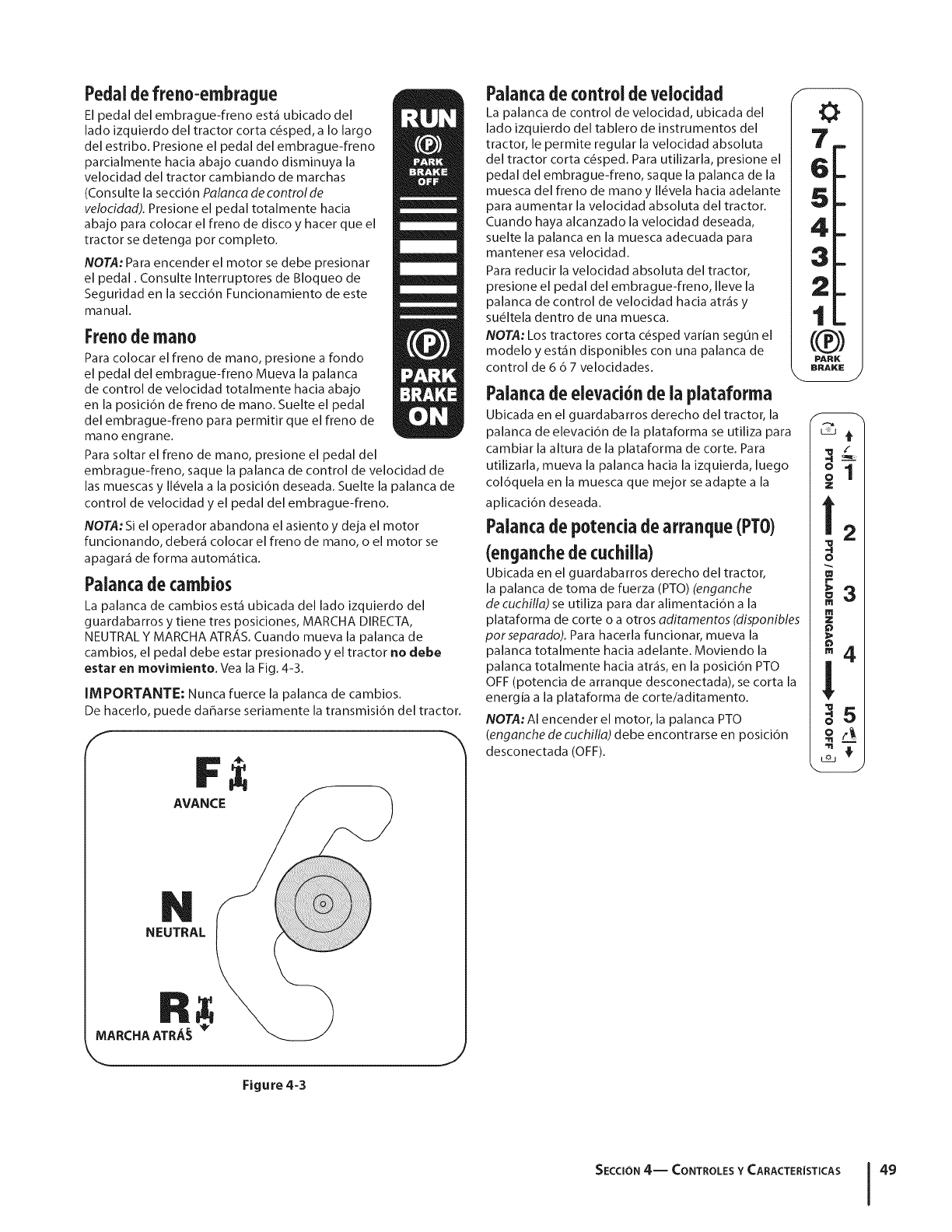
Pedaldefreno-embrague
El pedal del embrague-freno est_ ubicado del
lado izquierdo del tractor corta c_sped, a Io largo
del estribo. Presione el pedal del embrague-freno
parcialmente hacia abajo cuando disminuya la
velocidad del tractor cambiando de marchas
(Consulte la secci6n Palanca de control de
velocidad). Presione el pedal totalmente hacia
abajo para colocar el freno de disco y hacer que el
tractor se detenga pot completo.
NOTA: Para encender el motor se debe presionar
el pedal. Consulte Interruptores de Bloqueo de
Seguridad en la secci6n Funcionamiento de este
manual.
Frenodemano
Para colocar el freno de mano, presione a rondo
el pedal del embrague-freno Mueva la palanca
de control de velocidad totalmente hacia abajo
en la posici6n de freno de mano. Suelte el pedal
del embrague-freno para permitir que el freno de
mano engrane.
Para soltar el freno de mano, presione el pedal del
embrague-freno, saque la palanca de control de velocidad de
las muescas y II&vela a la posici6n deseada. Suelte la palanca de
control de velocidad y el pedal del embrague-freno.
NOTA: Si el operador abandona el asiento y deja el motor
funcionando, deber_ colocar el freno de mano, o el motor se
apagar_ de forma autom_tica.
Palaocadecarnbios
La palanca de cambios est_ ubicada del lado izquierdo del
guardabarros y tiene tres posiciones, MARCHA DIRECTA,
NEUTRAL Y MARCHA ATR_,S. Cuando mueva la palanca de
cambios, el pedal debe estar presionado y el tractor no debe
estar en movimiento. Vea la Fig. 4-3.
IMPORTANTE: Nunca fuerce la palanca de cambios.
De hacerlo, puede daharse seriamente la transmisi6n del tractor.
f
4_
AVANCE
NEUTRAL
Figure 4=3
J
Palancadecontrolde veioddad
La palanca de control de velocidad, ubicada del
lado izquierdo del tablero de instrumentos del
tractor, le permite regular la velocidad absoluta
del tractor corta c_sped. Para utilizarla, presione el
pedal del embrague-freno, saque la palanca de la
muesca del freno de mano y II_vela hacia adelante
para aumentar la velocidad absoluta del tractor.
Cuando haya alcanzado la velocidad deseada,
suelte la palanca en la muesca adecuada para
mantener esa velocidad.
Para reducir la velocidad absoluta del tractor,
presione el pedal del embrague-freno, Ileve la
palanca de control de velocidad hacia atr_s y
su_ltela dentro de una muesca.
NOTA: Los tractores corta c_sped varian segun el
modelo y est_n disponibles con una palanca de
control de 6 6 7 velocidades.
Palancade elevaci6nde la plataforrna
Ubicada en el guardabarros derecho del tractor, la
palanca de elevaci6n de la plataforma se utiliza para
cambiar la altura de la plataforma de corte. Para
utilizarla, mueva la palanca hacia la izquierda, luego
col6quela en la muesca que mejor se adapte a la
aplicaci6n deseada.
Palancade potenciadearranque(PTO)
(enganchedecuchilla)
Ubicada en el guardabarros derecho del tractor,
la palanca de toma de fuerza (PTO) (enganche
de cuchJlla) se utiliza para dar alimentaci6n a la
plataforma de corte o a otros adJtamentos (dJsponJbles
porseparado). Para hacerla funcionar, mueva la
palanca totalmente hacia adelante. Moviendo la
palanca totalmente hacia atr_s, en la posici6n PTO
OFF (potencia de arranque desconectada), se corta la
energia a la plataforma de corte/aditamento.
NOTA: AI encender el motor, la palanca PTO
(enganche de cuchlll_]) debe encontrarse en posici6n
desconectada (OFF).
m
Q 4
t2_ !
2:
4
II ')
k
m
z
m4
m -
o_
SECCI(SN 4-- CONTROLES Y CARACTER[STICAS 49
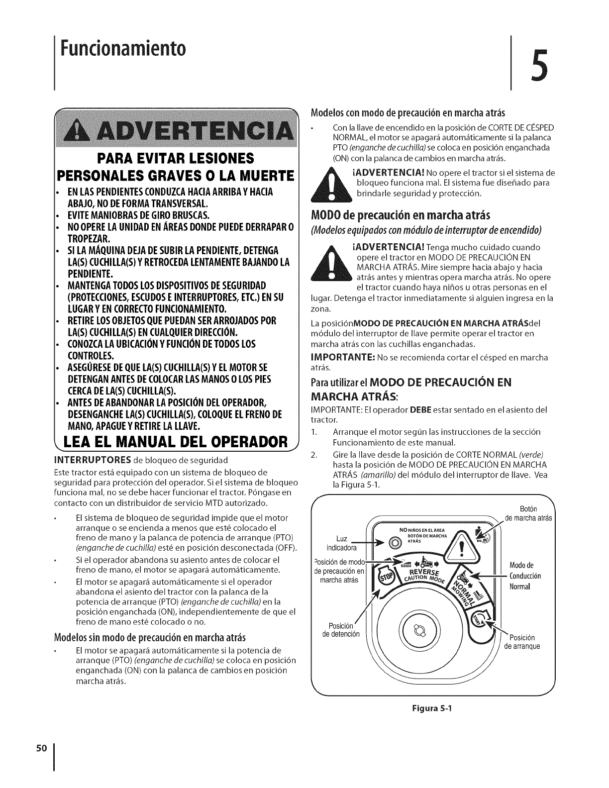
Funcionamiento
PARA EVITAR LESIONES
PERSONALES GRAVES 0 LA MUERTE
ENLASPENDIENTESCONDUZCAHACIAARRIBAYHACIA
ABAJO,NODEFORMATRANSVERSAL.
EVITEMANIOBRASDEGIROBRUSCAS.
NOOPERELAUNIDADENAREASDONDEPUEDEDERRAPAR0
TROPEZAR.
SILAMAQUINADEJADESUBIRLAPENDIENTE,DETENGA
LA(S)CUCHILLA(S)YRETROCEDALENTAMENTERAJANDOLA
PENDIENTE.
MANTENGATODOSLOSDISPOSITIVOSDESEGURIDAD
(PROTECCIONES,ESCUDOSEINTERRUPTORES,ETC.)ENSU
LUGARYENCORRECTOFUNCIONAMIENTO.
RETIRELOSOBJETOSQUEPUEDANSERARROJADOSPOR
LA(S)CUCHILLA(S)ENCUALQUIERDIRECCION.
CONOZCALAUBICACIONYFUNCIONDETODOSLOS
CONTROLES.
ASEGORESEDEQUEEA(S)CUCHILEA(S)YELMOTORSE
DETENGANANTESDECOLOCARLASMANOS0 LOSPIES
CERCADEEA(S)CUCHILEA(S).
ANTESDEABANDONARLAPOSICIONDEEOPERADOR,
DESENGANCHELA(S)CUCHILLA(S),COLOQUEELFRENODE
MANO,APAGUEYRETIRELALEAVE.
LEA EL MANUAL DEL OPERADORj
INTERRUPTORES de bloqueo de seguridad
Este tractor est_ equipado con un sistema de bloqueo de
seguridad para protecci6n del operador. Si el sistema de bloqueo
funciona mal, no se debe hacer funcionar el tractor. P6ngase en
contacto con un distribuidor de servicio MTD autorizado.
El sistema de bloqueo de seguridad impide que el motor
arranque o se encienda a menos que est6 colocado el
freno de mano y la palanca de potencia de arranque (PTO)
(enganche de cuchilla) est_ en posici6n desconectada (OFF).
Si el operador abandona su asiento antes de colocar el
freno de mano, el motor se apagar& autom_ticamente.
El motor se apagar_ autom_ticamente si el operador
abandona el asiento del tractor con la palanca de la
potencia de arranque (PTO) (enganche de cuchilla) en la
posici6n enganchada (ON), independientemente de que el
freno de mano est_ colocado o no.
Modelossin modo de precauci6nen marchaatr_s
El motor se apagar_ autom_ticamente si la potencia de
arranque (PTO) (enganche de cuchilla)se coloca en posici6n
enganchada (ON) con la palanca de cambios en posici6n
marcha atr_s.
Modelosconmodo deprecaud6n en marchaatr_s
Con la Ilave de encendido en la posici6n de CORTE DE C¢SPED
NORMAL, el motor se apagar_ autom_ticamente si la palanca
PTO (enganche de cuchilla) se coloca en posici6n enganchada
(ON) con la palanca de cambios en marcha atr_s.
_iADVERTENCIA! No el si el sistema de
opere tractor
bloqueo funciona mal. El sistema rue disehado para
brindarle seguridad y protecci6n.
MOD0de precauci6,e. marchaatr_s
(Modelosequipadosconm6dulo deinterruptor deencendido)
|
AiADVERTENCIA. Tenga mucho cuidadocuando
A _k opere el tractor en MODO DE PRECAUClON EN
MARCHA ATRAS. Mire siempre hacia abajo y hacia
atr_s antes y mientras opera marcha atr_s. No opere
el tractor cuando haya nifios u otras personas en el
lugar. Detenga el tractor inmediatamente si alguien ingresa en la
zona.
La posici6nMODO DE PRECAUCION EN MARCHA ATRASdel
m6dulo del interruptor de Ilave permite operar el tractor en
marcha atr_s con las cuchillas enganchadas.
IMPORTANTE: No se recomienda cortar el c_sped en marcha
atr_s.
Para utilizar el MODO DE PRECAUCI()N EN
MARCHA ATRAS:
IMPORTANTE: El operador DEBE estar sentado en el asiento del
tractor.
1. Arranque el motor segun las instrucciones de la secci6n
Funcionamiento de este manual.
2. Gire la Ilave desde la posici6n de CORTE NORMAL (verde)
hasta la posici6n de MODO DE PRECAUCION EN MARCHA
ATRAS (amarillo) del m6dulo del interruptor de Ilave. Vea
la Figura 5-1.
f Bot6n '_
de marchaatrAs
NONil_O$ EN EL AREA
BOT(_N DE MARCHA
Luz 0 ATR_S
indicadora
=osici6nde modo Modode
de precauci6nen
marchaatr_.s - Conducci6n
Normal
de detenci6n
de arranque
Figura5-1
J
3. PresioneelBOTONDEMARCHAATRAS(botdn triangular de
colornaranja) en la esquina superior derecha del m6dulo
del interruptor de Ilave. La luz indicadora roja en la esquina
superior izquierda del m6dulo del interruptor de Ilave se
mantiene encendida (ON) mientras est_ activado. Vea la
Figura 5-1.
4. Una vez activado el Modo dePrecaucidn enMarcha
Atrds (con la luz indicadora encendida), el tractor podr_
conducirse en marcha atr_s con las cuchillas de corte (PTO)
enganchadas.
5. Siempre mire hacia abajo y hacia atr&s antes y mientras
opera en marcha atr_s, para asegurarse de que no haya
niffos en el _rea.
6. Una vez retomada la marcha hacia adelante, vuelva a
colocar la Ilave en la posici6n CORTENORMAL.
[MPORTANTE: El MODO DE PRECAUCION EN MARCHA ATRAS
permanece activado hasta que:
a. Se coloca la Ilave en la posici6n de CORTE NORMAL o
en la posici6n STOP (detenci6n).
b. El operador coloca el freno de mano, presionando
totalmente el pedal de freno-embrague y
manteni6ndolo mientras mueve la palanca de
control de velocidad a la posici6n FRENO DE MANO.
Colocad6ndei freno demano
Paracel0carel frene de mane:
1. Presione totalmente el pedal del embrague-freno y
mant_ngalo hacia abajo con el pie.
2. Mueva la palanca de control de velocidad totalmente hacia
abajo en la posici6n de freno de mano.
3. Suelte el pedal del embrague-freno para permitir que el
freno de mano engrane.
Parasacarel freno de mane:
1. Presione el pedal del embrague-freno, saque la palanca
de control de velocidad de la posici6n de freno de
estacionamiento y II_vela a la velocidad deseada.
Fijaci6n de ia aitura de torte
1. Seleccione la posici6n de altura de la plataforma de corte
colocando la palanca de elevaci6n de la plataforma en
cualquiera de las seis muescas de diferente altura de corte,
del lado derecho del guardabarros.
2. Ajuste las ruedas de la plataforma (si el vehiculo est,1
equipado con elias) segun las instrucciones de la secci6n
Configuraci6n y montaje que figuran en partes anteriores
de este manual, para que queden a una distancia de entre
1/4de pulgada y 1/2pulgada pot encima del terreno, cuando
el tractor se encuentre en una superficie lisa y plana, como,
pot ejemplo, un camino de entrada particular.
_iADVERTENCIA! Mantenga las manos y pies
alejados de la abertura de descarga de la plataforma
de corte.
IVOTA: Las ruedas de la plataforma (en los modelos equipados
con elias) constituyen un mecanismo para el cuidado del
c_sped y no fueron diseffadas para soportar el peso de la
plataforma de corte. Consulte la secci6n Nivelaci6n en la secci6n
Mantenimiento de este manual para obtener instrucciones
detalladas sobre diferentes ajustes de la plataforma.
Encendidodei motor
_ADVERTENCIA! No opere el tractor si el sistema
de bloqueo funciona mal. El sistema fue diseffado
para brindarle seguridad y protecci6n.
3.
4.
5.
NOTA: Consulte las instrucciones para el Ilenado de gasolina y
aceite en la secci6n Montaje y configuraci6n de este manual.
1. Inserte la Ilave del tractor en el interruptor de encendido.
2. Coloque la palanca de la potencia de arranque (PTO)
(enganche de cuchilla) en la posici6n OFF (desconectada).
Coloque el freno de mano del tractor.
Active el control del obturador.
Gire la Ilave de encendido en el sentido de las agujas del
reloj hasta la posici6n START (ENCENDIDO). Una vez que
arranque el motor, suelte la Ilave. Volver_i a la posici6n ON
(o de torte normal).
_PRECAUCI6N: NO mantenga la Ilave en la
posici6n START (ARRANQUE) durante m_is de diez
segundos pot vez. Si Io hace, puede ocasionar dahos
al arrancador el_ctrico del motor.
6. Despu_s de que arranque el motor, desactive el control del
obturador y coloque el control del regulador en posici6n
FAST (velocidad r_ipida).
NOTA: NO deje el control del obturador activado mientras
opera el tractor. Si Io hace, se generar_i una mezcla "rica" de
combustibles, Io cual har_i que el motor pierda intensidad.
Detenci6n del motor
_! ADVERTENCIA! Si golpea contra algun objeto
extraffo, detenga el motor, desconecte el(los)
cable(s) de la bujia y conecte el motor a masa.
Inspeccione minuciosamente la m_iquina para ver
si est,1 dahada. Repare el daho antes de volver a
arrancar el motor y operar la m_iquina.
1. Si las cuchillas est,1 n enganchadas, coloque la palanca de
la potencia de arranque (PTO) (enganche de cuchilla) en la
posici6n OFF (desconectada).
2. Gire la Ilave de encendido en sentido contrario a las agujas
del reloj a la posici6n STOP (detenci6n).
3. Retire la Ilave del interruptor de encendido para evitar que
alguien encienda accidentalmente el motor.
SECClON 5-- FUNCIONAMIENTO 51
Conducci6ndeltractor
IADVERTENCIA! Evite arrancar subitamente,
desarrollar excesiva velocidad y detenerse de
repente.
iADVERTENCIA! No abandone el asiento del
tractor sin colocar primero la palanca de la potencia
de arranque PTO (enganche de cuchilla) en la posici6n
(OFF) (desenganchada), presionando el pedal del
freno y colocando el freno de mano. Si deja el tractor
sin vigilancia, apague el motor y retire la Ilave de
encendido.
iADVERTENCIA! Siempre mire hacia abajo y hacia
atr_s antes y mientras se desplaza marcha atr_s, para
evitar un accidente.
1. Presione el pedal de freno para soltar el freno de mano y
deje que suba el pedal.
2. Mueva la palanca del regulador a la posici6n FAST
(VELOCIDAD R_,PIDA, representada pot una liebre).
3. Coloque la palanca de cambios en posici6n FORWARD
(marcha directa) o REVERSE (marcha atr_s).
IMPORTANTE: NO use la palanca de cambios para cambiar
la direcci6n de desplazamiento mientras el tractor est_ en
movimiento. Siempre use el pedal de freno para detener el
tractor pot completo antes de hacer el cambio.
4. Suelte el freno de mano presionando el pedal del
embrague-freno y colocando la palanca de control de
velocidad en la posici6n deseada.
IMPORTANTE: Quienes utilicen la m_quina pot primera vez
deben usar las posiciones de velocidad 1 6 2. Familiaricese pot
completo con el funcionamiento y los controles del tractor antes
de operar la m_quina en posiciones de mayor velocidad.
5. Suelte el pedal del embrague-freno lentamente para poner
la unidad en movimiento.
6. El tractor corta c_sped se detiene presionando el pedal del
embrague-freno.
NOTA:AI operar la unidad inicialmente, habr_ poca diferencia
entre las dos velocidades m_s altas hasta que las correas se hayan
asentado en las poleas durante el periodo de ablande.
_i ADVERTENCIA! Antes de abandonar la posici6n
del operador, desenganche las cuchillas, coloque
la palanca en neutral, coloque el freno de mano,
apague el motor y retire la Ilave de encendido.
IMPORTANTE: Siempre que detenga el tractor por cualquier
razdn en un _rea de c_sped, haga Io siguiente:
1. Coloque la palanca de cambios en neutral,
2. Coloque el freno de estacionamiento,
3. Apague el motor y retire la Ilave. Eso permitir_ reducir al
minimo la posibilidad de que su c_sped resulte quemado
por el escape caliente del motor en funcionamiento.
Si la unidad se detiene con el control de velocidad en la posici6n
de alta velocidad, o si la unidad no funciona con la palanca de
control de velocidad en la posicidn de baja velocidad, realice Io
siguiente:
1. Coloque la palanca de cambios en posicidn NEUTRAL.
2. Vuelva a encender el motor.
3. Coloque la palanca de control de velocidad en la posicidn
de velocidad m_s alta.
4. Suelte completamente el pedal del embrague-freno.
5. Presione el pedal del embrague-freno.
6. Coloque la palanca de control de velocidad en la posici6n
deseada.
7. Coloque la palanca de cambios en la posici6n FORWARD
(marcha directa) o REVERSE (marcha atr_s), y siga el
procedimiento normal de operaci6n.
Operaci6n en pendientes
Consulte el INDICADOR DE PENDIENTES en la secci6n Medidas
importantes de seguridad del manual para contribuir a
determinar en qu_ pendientes puede operar el tractor con
seguridad.
_IL ADVERTENCIA! No corte el c6sped en
inclinaciones mayores a 15 grados (elevaci6n
aproximada de 2 1/2 pies pot cada 10 pies). El tractor
podria voltearse y causar lesiones severas.
Corte hacia arriba y abajo de las pendientes, NUNCA en
forma transversal.
Tenga cuidado cuando cambie de direccidn al operar en
pendiente.
Est_ atento a los hoyos, surcos, baches, rocas u otros
objetos ocultos. El terreno desnivelado puede voltear la
m_quina. El c_sped alto puede ocultar obst_culos.
Evite realizar giros cuando opere en una pendiente. Si
debiera realizar un giro, baje de la pendiente. Subir una
pendiente aumenta enormemente las posibilidades de que
el vehiculo d_ una vuelta de campana.
Evite detenerse cuando suba una pendiente. Si fuese
necesario detenerse mientras sube una pendiente,
arranque suave y cuidadosamente para reducir la
posibilidad de que el tractor d_ una voltereta hacia atr_s.
Enganchede lascuchiilas
Cuando se engancha la potencia de arranque PTO (enganche de
cuchillas) se suministra alimentaci6n a la plataforma de corte o
a otros aditamentos (disponiblesporseparado). Para conectar las
cuchillas, haga Io siguiente:
1. Mueva la palanca de control del regulador a la posici6n
FAST (VELOCIDAD R_,PIDA, representada pot una liebre).
2. Tome la potencia de arranque PTO (enganche de cuchillas)
y gfrela totalmente hacia adelante hasta la posici6n
enganchada (ON).
3. Mantenga la palanca del regulador en la posici6n FAST
(velocidad r_pida, representada por una liebre), para
un uso m_s eficaz de la plataforma de corte o de otros
accesorios (disponibles por separado).
NOTA: Modelos con modo de precauci6n en marcha atr_s: El
motor se apagar& autom&ticamente si la potencia de arranque
(PTO) est_ enganchada con la palanca de cambios en posicidn de
marcha atr_s con la Ilave de encendido en la posicidn de CORTE
NORMAL.
Modelossin Modo de precaud6n en marchaatr_s:
La palanca de potencia de arranque PTO (enganche de cuchifla)
debe estar en la posici6n desconec tada (OFF) al arrancar el motor,
cuando se desplaza marcha atrds y si el operador abandona su
asiento. Consulte Interruptores de Bloqueo de Seguridad en la
secci6n Funcionamiento de este manual.
Utilizad6ndelapalancadeelevad6ndelaplataferma
Para elevar la plataforma de corte, mueva la palanca de elevaci6n
de la plataforma hacia la izquierda y col6quela en la muesca que
mejor se adapte a la aplicaci6n deseada. Consulte Ajuste de la
altura de corte unas p_ginas atr_s en esta misma secci6n.
SECCION 5-- FUNCIONAMIENTO
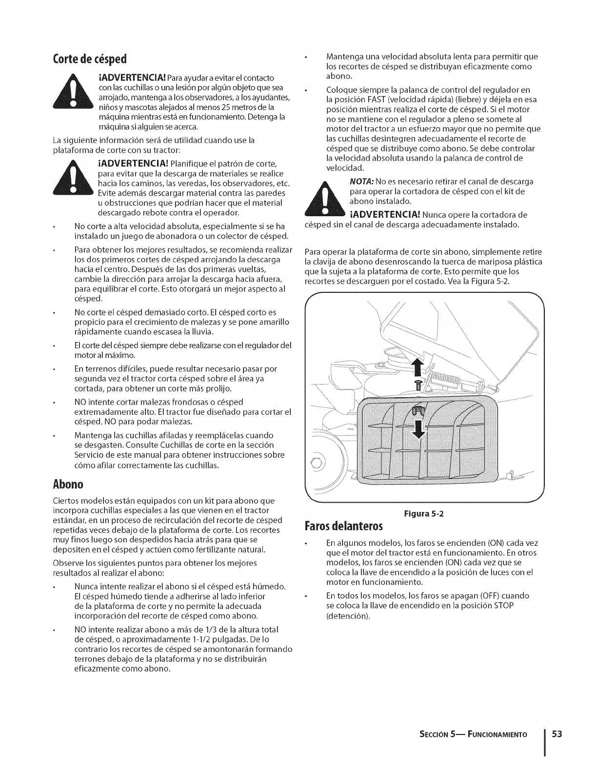
Cortedec sped
i_ IADVERTENCIA! Para ayudar a evitar el contacto
con las cuchillas o una lesi6n pot algun objeto que sea
arrojado, mantenga a los observadores, a los ayudantes,
ni_os y mascotas alejados al menos 25 metros de la
m&quina mientras estk en funcionamiento. Detenga la
m_quina si alguien se acerca.
La siguiente informaci6n ser_ de utilidad cuando use la
plataforma de corte con su tractor:
_ADVERTENCIA! Planifique el patr6n de corte,
para evitar que la descarga de materiales se realice
hacia los caminos, las veredas, los observadores, etc.
Evite adem_s descargar material contra las paredes
u obstrucciones que podrian hacer que el material
descargado rebote contra el operador.
No corte a alta velocidad absoluta, especialmente si se ha
instalado un juego de abonadora o un colector de c_sped.
Para obtener los mejores resultados, se recomienda realizar
los dos primeros cortes de c_sped arrojando la descarga
hacia el centro. Despu&s de las dos primeras vueltas,
cambie la direcci6n para arrojar la descarga hacia afuera,
para equilibrar el corte. Esto otorgar_ un mejor aspecto al
c_sped.
No corte el c_sped demasiado corto. El c&sped corto es
propicio para el crecimiento de malezas y se pone amarillo
r_pidamente cuando escasea la Iluvia.
El corte del c_sped siempre debe realizarse con el regulador del
motor al m_ximo.
En terrenos dificiles, puede resultar necesario pasar pot
segunda vez el tractor corta c_sped sobre el _rea ya
cortada, para obtener un corte m_s prolijo.
NO intente cortar malezas frondosas o c_sped
extremadamente alto. El tractor fue dise_ado para cortar el
c_sped, NO para podar malezas.
Mantenga las cuchillas afiladas y reempl_celas cuando
se desgasten. Consulte Cuchillas de corte en la secci6n
Servicio de este manual para obtener instrucciones sobre
cdmo afilar correctamente las cuchillas.
Abono
Ciertos modelos est_n equipados con un kit para abono que
incorpora cuchillas especiales alas que vienen en el tractor
est_ndar, en un proceso de recirculaci6n del recorte de c_sped
repetidas veces debajo de la plataforma de corte. Los recortes
muy finos luego son despedidos hacia atr_s para que se
depositen en el c_sped y actuen como fertilizante natural.
Observe los siguientes puntos para obtener los mejores
resultados al realizar el abono:
Nunca intente realizar el abono si el c_sped est_ humedo.
El c_sped h0medo tiende a adherirse al lado inferior
de la plataforma de corte y no permite la adecuada
incorporaci6n del recorte de c_sped como abono.
NO intente realizar abono a m_s de 1/3 de la altura total
de c_sped, o aproximadamente 1-1/2 pulgadas. De Io
contrario los recortes de c_sped se amontonar_n formando
terrones debajo de la plataforma y no se distribuir_n
eficazmente como abono.
Mantenga una velocidad absoluta lenta para permitir que
los recortes de c_sped se distribuyan eficazmente como
abono.
Coloque siempre la palanca de control del regulador en
la posici6n FAST (velocidad r_pida) (liebre) y d_jela en esa
posici6n mientras realiza el corte de c_sped. Si el motor
no se mantiene con el regulador a pleno se somete al
motor del tractor a un esfuerzo mayor que no permite que
las cuchillas desintegren adecuadamente el recorte de
c_sped que se distribuye como abono. Se debe controlar
la velocidad absoluta usando la palanca de control de
velocidad.
NOTA: No es necesario retirar el canal de descarga
para operar la cortadora de c_sped con el kit de
abono instalado.
iADVERTENCIA! Nunca opere la cortadora de
c_sped sin el canal de descarga adecuadamente instalado.
Para operar la plataforma de corte sin abono, simplemente retire
la clavija de abono desenroscando la tuerca de mariposa pl_stica
que la sujeta a la plataforma de corte. Esto permite que los
recortes se descarguen por el costado. Vea la Figura 5-2.
J
Figura 5-2
Farosdelanteros
En algunos modelos, los faros se encienden (ON) cada vez
que el motor del tractor est_ en funcionamiento. En otros
modelos, los faros se encienden (ON) cada vez que se
coloca la Ilave de encendido a la posici6n de luces con el
motor en funcionamiento.
En todos los modelos, los faros se apagan (OFF) cuando
se coloca la llave de encendido en la posicidn STOP
(detencidn).
SECTION 5-- FUNCIONAMIENTO 53
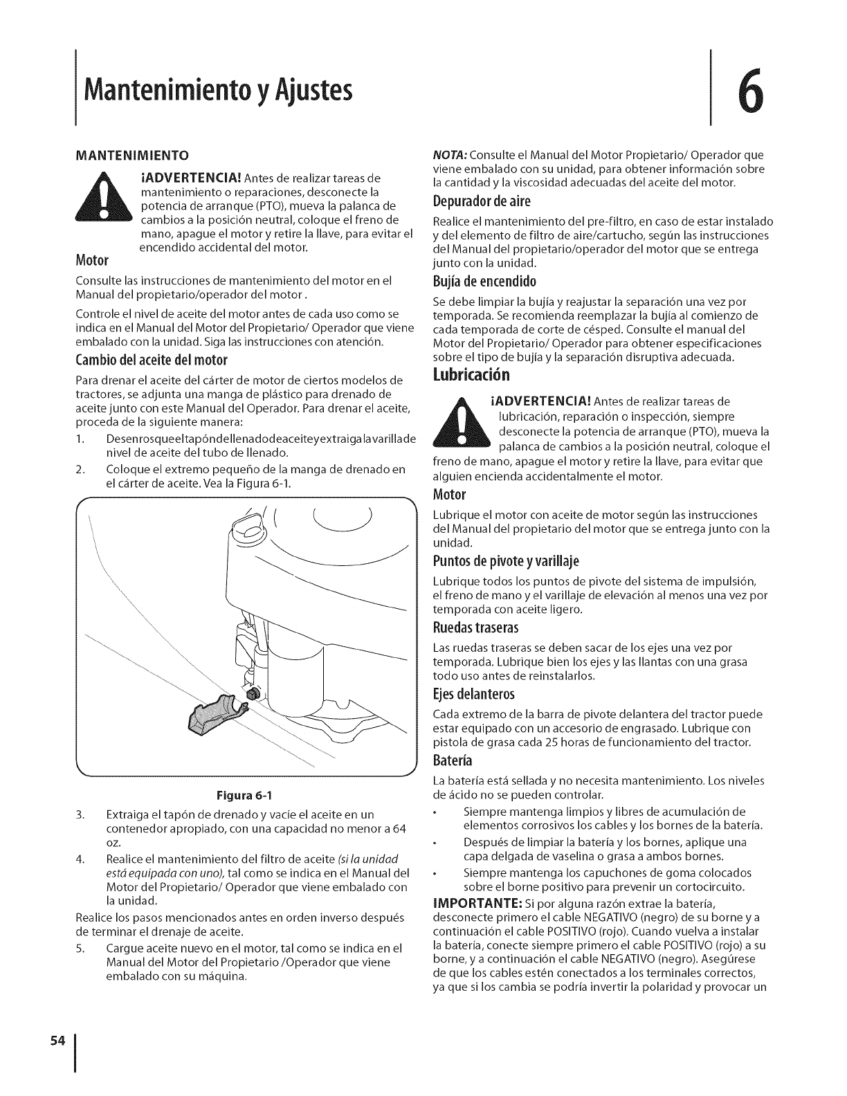
MantenimientoyAjustes
MANTENIMIENTO
Motor
iADVERTENCIA! Antes de realizar tareas de
mantenimiento o reparaciones, desconecte la
potencia de arranque (PTO), mueva la palanca de
cambios a la posici6n neutral, coloque el freno de
mano, apague el motor y retire la Ilave, para evitar el
encendido accidental del motor.
Consulte las instrucciones de mantenimiento del motor en el
Manual del propietario/operador del motor.
Controle el nivel de aceite del motor antes de cada uso como se
indica en el Manual del Motor del Propietario/Operador que viene
embalado con la unidad. Siga las instrucciones con atenci6n.
Cambi0del aceite del motor
Para drenar el aceite del c_1rter de motor de ciertos modelos de
tractores, se adjunta una manga de pl_istico para drenado de
aceite junto con este Manual del Operador. Para drenar el aceite,
proceda de la siguiente manera:
1. Desenrosqueeltapdndellenadodeaceiteyextraiga lavarillade
nivel de aceite del tubo de Ilenado.
2.
f
Coloque el extremo peque_o de la manga de drenado en
el c_rter de aceite. Vea la Figura 6-1.
,\ ,\
\\\\\
Figura 6-1
3. Extraiga el tap6n de drenado y vacie el aceite en un
contenedor apropiado, con una capacidad no menor a 64
OZ,
4. Realice el mantenimiento del filtro de aceite (sila unidad
estd equipada con uno), tal como se indica en el Manual del
Motor del Propietario/Operador que viene embalado con
la unidad.
Realice los pasos mencionados antes en orden inverso despu_s
de terminar el drenaje de aceite.
5. Cargue aceite nuevo en el motor, tal como se indica en el
Manual del Motor del Propietario/Operador que viene
embalado con su m_iquina.
NOTA: Consulte el Manual del Motor Propietario/Operador que
viene embalado con su unidad, para obtener informaci6n sobre
la cantidad y la viscosidad adecuadas del aceite del motor.
Depurad0rde aire
Realice el mantenimiento del pre-filtro, en caso de estar instalado
y del elemento de filtro de aire/cartucho, segOn las instrucciones
del Manual del propietario/operador del motor que se entrega
junto con la unidad.
Bujia deencendido
Se debe limpiar la bujia y reajustar la separaci6n una vez pot
temporada. Se recomienda reemplazar la bujia al comienzo de
cada temporada de corte de c_sped. Consulte el manual del
Motor del Propietario/Operador para obtener especificaciones
sobre el tipo de bujia y la separaci6n disruptiva adecuada.
Lubricaci6n
ADVERTENCIA! Antes de realizar tareas de
lubricaci6n, reparaci6n o inspecci6n, siempre
desconecte la potencia de arranque (PTO), mueva la
palanca de cambios a la posicidn neutral, coloque el
freno de mano, apague el motor y retire la Ilave, para evitar que
alguien encienda accidentalmente el motor.
Motor
Lubrique el motor con aceite de motor segOn las instrucciones
del Manual del propietario del motor que se entrega junto con la
unidad.
Puntosde pivoteyvarillaje
Lubrique todos los puntos de pivote del sistema de impulsi6n,
el freno de mano y el varillaje de elevaci6n al menos una vez pot
temporada con aceite ligero.
Ruedastraseras
Las ruedas traseras se deben sacar de los ejes una vez pot
temporada. Lubrique bien los ejes y las Ilantas con una grasa
todo uso antes de reinstalarlos.
Ejesdelanter0s
Cada extremo de la barra de pivote delantera del tractor puede
estar equipado con un accesorio de engrasado. Lubrique con
pistola de grasa cada 25 horas de funcionamiento del tractor.
Bateda
La bateria est,1 sellada y no necesita mantenimiento. Los niveles
de _icido no se pueden controlar.
Siempre mantenga limpios y libres de acumulaci6n de
elementos corrosivos los cables y los bornes de la bateria.
Despu_s de limpiar la bateria y los bornes, aplique una
capa delgada de vaselina o grasa a ambos bornes.
Siempre mantenga los capuchones de goma colocados
sobre el borne positivo para prevenir un cortocircuito.
IMPORTANTE: Si por alguna razdn extrae la bateria,
desconecte primero el cable NEGATIVO (negro) de su borne y a
continuaci6n el cable POSITIVO (rojo). Cuando vuelva a instalar
la bateria, conecte siempre primero el cable POSITIVO (rojo) a su
borne, y a continuaci6n el cable NEGATIVO (negro). Asegurese
de que los cables est_n conectados a los terminales correctos,
ya que si los cambia se podria invertir la polaridad y provocar un
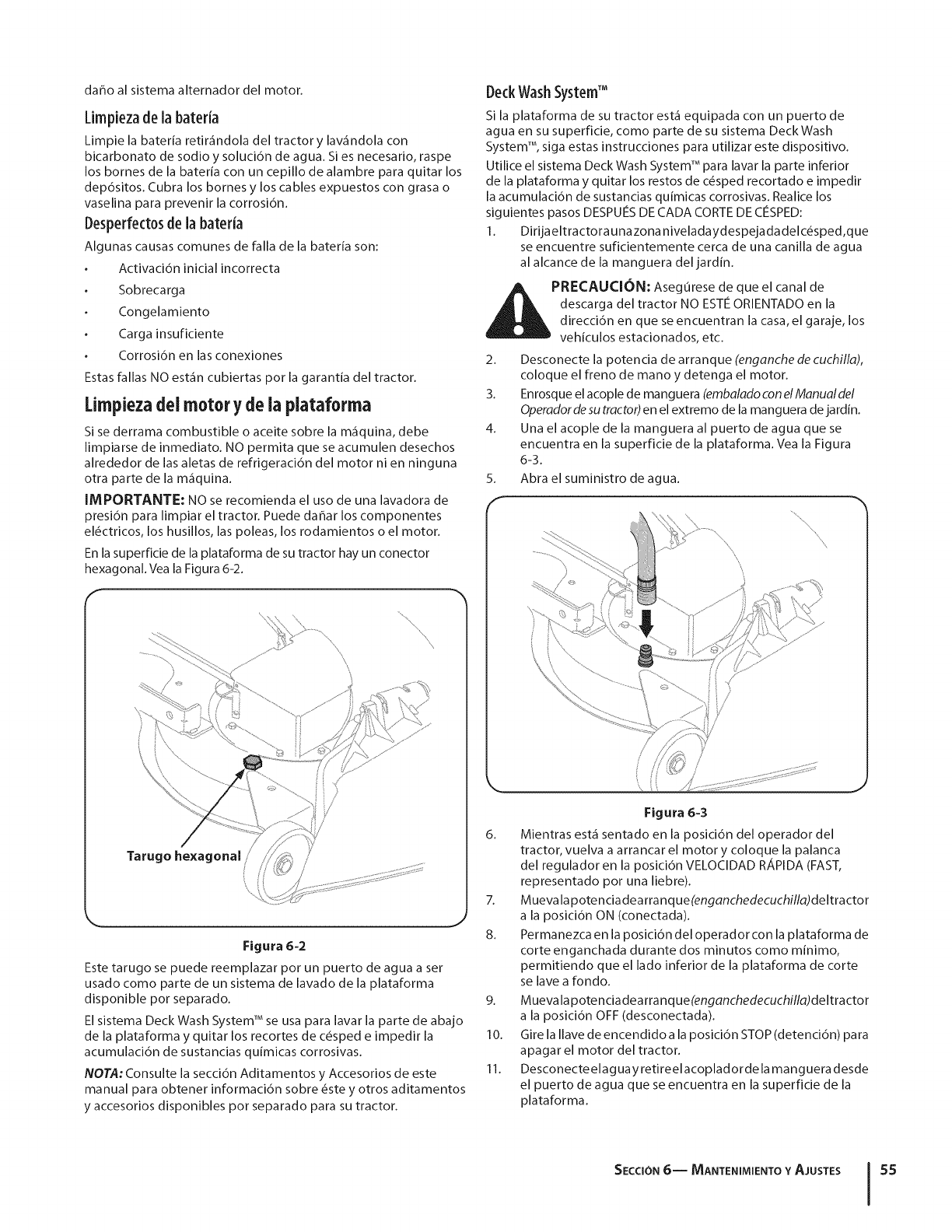
dafloalsistemaalternadordelmotor.
Limpiezade la bateria
Limpie la baterfa retir_ndola del tractor y lav_ndola con
bicarbonato de sodio y soluci6n de agua. Si es necesario, raspe
los bornes de la baterfa con un cepillo de alambre para quitar los
dep6sitos. Cubra los bornes y los cables expuestos con grasa o
vaselina para prevenir la corrosi6n.
Desperfect0sde la bateria
Algunas causas comunes de falla de la bateria son:
Activaci6n inicial incorrecta
Sobrecarga
Congelamiento
Carga insuficiente
Corrosi6n en las conexiones
Estas fallas NO est_n cubiertas pot la garantia del tractor.
[impieza dei motor y de ia plataforma
Si se derrama combustible o aceite sobre la m_quina, debe
limpiarse de inmediato. NO permita que se acumulen desechos
alrededor de las aletas de refrigeraci6n del motor ni en ninguna
otra parte de la m_quina.
IMPORTANTE: NO se recomienda el uso de una lavadora de
presidn para limpiar el tractor. Puede daflar los componentes
el_ctricos, los husillos, las poleas, los rodamientos o el motor.
En la superficie de la plataforma de su tractor hay un conector
hexagonal. Vea la Figura 6-2.
Figura 6-2
Este tarugo se puede reemplazar pot un puerto de agua a set
usado como parte de un sistema de lavado de la plataforma
disponible pot separado.
El sistema Deck Wash System TM se usa para lavar la parte de abajo
de la plataforma y quitar los recortes de c_sped e impedir la
acumulaci6n de sustancias qufmicas corrosivas.
NOTA: Consulte la secci6n Aditamentos y Accesorios de este
manual para obtener informaci6n sobre _ste y otros aditamentos
y accesorios disponibles pot separado para su tractor.
DeckWashSystemTM
Si la plataforma de su tractor est_ equipada con un puerto de
agua en su superficie, como parte de su sistema DeckWash
System TM, siga estas instrucciones para utilizar este dispositivo.
Utilice el sistema Deck Wash System TM para lavar la parte inferior
de la plataforma y quitar los restos de c_sped recortado e impedir
la acumulaci6n de sustancias quimicas corrosivas. Realice los
siguientes pasos DESPUES DE CADA CORTE DE CleSPED:
1. Dirijaeltractora unazona niveladaydespejada delc_sped,que
se encuentre suficientemente cerca de una canilla de agua
al alcance de la manguera del jardin.
_1PRECAUCI6N: Aseg0rese el canal de
de que
descarga del tractor NO ESTE ORIENTADO en la
direcci6n en que se encuentran la casa, el garaje, los
vehiculos estacionados, etc.
2. Desconecte la potencia de arranque (enganche de cuchilla),
coloque el freno de mano y detenga el motor.
3. Enrosque el acople de manguera (embalado con elManualdel
Operadordesu tractor)en el extremo de la manguera de jardin.
4. Una el acople de la manguera al puerto de agua que se
encuentra en la superficie de la plataforma. Vea la Figura
5_
f
6-3,
Abra el suministro de agua.
Figura 6-3
6. Mientras est_ sentado en la posici6n del operador del
tractor, vuelva a arrancar el motor y coloque la palanca
del regulador en la posici6n VELOClDAD RAPIDA (FAST,
representado pot una liebre).
7. Muevalapotenciadearranque(enganchedecuchilla)deltractor
a la posici6n ON (conectada).
8. Permanezca en la posici6n del operador con la plataforma de
corte enganchada durante dos minutos como minimo,
permitiendo que el lado inferior de la plataforma de corte
se lave a rondo.
9. Muevalapotenciadearranque(enganchedecuchilla)deltractor
a la posicidn OFF (desconectada).
10. Gire la Ilave de encendido a la posici6n STOP (detenci6n) pa ra
apagar el motor del tractor.
11. Desconecteelaguay retireelacopladorde la manguera desde
el puerto deagua que seencuentra en la superficie de la
plataforma.
SECCION 6-- MANTENIMIENTO Y AJUSTES .55
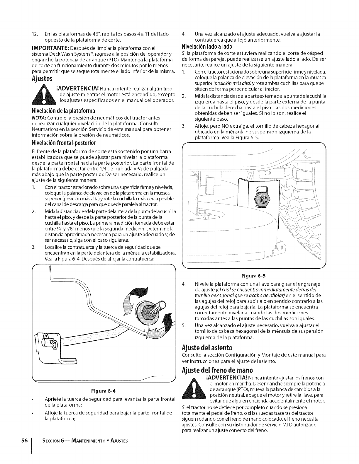
12. En las plataformas de 46", repita los pasos 4 a 11 del lado
opuesto de la plataforma de corte.
IMPORTANTE: Despu_s de limpiar la plataforma con el
sistema Deck Wash System TM, regrese a la posici6n del operador y
enganche la potencia de arranque (PTO). Mantenga la plataforma
de corte en funcionamiento durante dos minutos pot Io menos
para permitir que se seque totalmente el lado inferior de la misma.
Ajustes
I_LiADVERTENCIA! Nunca intente realizar alg0n tipo
de ajuste mientras el motor est_ encendido, excepto
los ajustes especificados en el manual del operador.
Nivelad6n de la plataf0rma
NOTA: Controle la presi6n de neum_ticos del tractor antes
de realizar cualquier nivelaci6n de la plataforma. Consulte
Neum_ticos en la secci6n Servicio de este manual para obtener
informaci6n sobre la presi6n de neum_ticos.
Nivelad6n fr0ntal-p0steri0r
El frente de la plataforma de corte est_ sostenido por una barra
estabilizadora que se puede ajustar para nivelar la plataforma
desde la parte frontal hacia la parte posterior. La parte frontal de
la plataforma debe estar entre 1/4 de pulgada y 3/sde pulgada
m_s abajo que la parte posterior. De ser necesario, realice un
ajuste de la siguiente manera:
1. Con el tractor estacionado sobre una superficie firme y nivelada,
coloque la palanca de elevaci6n de la plataforma en la muesca
superior (posici6n m_s alta) y rote la cuchilla Io m_s cerca posible
del canal de descarga para que quede paralela al tractor.
2. Midaladistanciadesdela partedelanteradela puntadelacuchilla
hasta el piso, y desde la parte posterior de la punta de la
cuchilla hasta el piso. La primera medici6n tomada debe estar
entre 1/4"y 3/8" menos que la segunda medici6n. Determine la
distancia aproximada necesaria para un ajuste adecuado y, de
ser necesario, siga con el paso siguiente.
3. Localice la contratuerca y la tuerca de seguridad que se
encuentran en la parte delantera de la m_nsula estabilizadora.
Vea la Figura 6-4. Despu_s de aflojar la contratuerca:
r tt
Figura 6=4
Apriete la tuerca de seguridad para levantar la parte frontal
de la plataforma;
Afloje la tuerca de seguridad para bajar la parte frontal de
la plataforma;
SECCI6N 6-- MANTENIMIENTO Y AJUSTES
4. Una vez alcanzado el ajuste adecuado, vuelva a ajustar la
contratuerca que afloj6 anteriormente.
Nivelaci6n lad0a lad0
Si la plataforma de corte estuviera realizando el corte de c_sped
de forma despareja, puede realizarse un ajuste lado a lado. De set
necesario, realice un ajuste de la siguiente manera:
1. Con el tractorestacionado sobre una superficie firmey nivelada,
2.
3.
coloque la palanca de elevaci6n de la plataforma en la muesca
superior (posici6n mdsalta) y rote ambas cuchillas para que se
situen de forma perpendicular al tractor.
Midala distancia desdela parteexterna dela puntadelacuchilla
izquierda hasta el piso, y desde la parte externa de la punta
de la cuchilla derecha hasta el piso. Las dos mediciones
obtenidas deben set iguales. Si no Io son, realice el
siguiente paso.
Afloje, pero NO extraiga, el tornillo de cabeza hexagonal
ubicado en la m6nsula de suspensi6n izquierda de la
plataforma. Vea la Figura 6-5.
\\
J
Figura 6=5
4. Nivele la plataforma con una Ilave para girar el engranaje
de ajuste (el cual seencuentra inmediatamente detrds del
tomillo hexagonal que se acaba de aflojar) en el sentido de
las agujas del reloj para subirla o en sentido contrario alas
agujas del reloj para bajarla. La plataforma se encuentra
correctamente nivelada cuando las dos mediciones
tomadas antes alas puntas de las cuchillas son iguales.
5. Una vez alcanzado el ajuste necesario, vuelva a ajustar el
tornillo de cabeza hexagonal de la m_nsula de suspensi6n
izquierda de la plataforma.
Ajustedel asiento
Consulte la secci6n Configuraci6n y Montaje de este manual para
vet instrucciones para el ajuste del asiento.
Ajustedelfreno de raano
iADVERTENCIA! Nunca intente ajustar los frenos con
el motor en marcha. Desenganche siempre la potencia
de arranque (PTO), mueva la palanca de cambios a la
posicidn neutral, apague el motor y retire la Ilave, para
evitar que alguien encienda accidentalmente el motor.
Siel tractor no se detiene por completo cuando se presiona
totalmente el pedal de freno, o si las ruedas traseras del tractor
siguen rodando con el ffeno de mano colocado, el freno necesita
ajustes. Consulte con su distribuidor de servicio MTD autorizado
para realizar un ajuste correcto del freno.
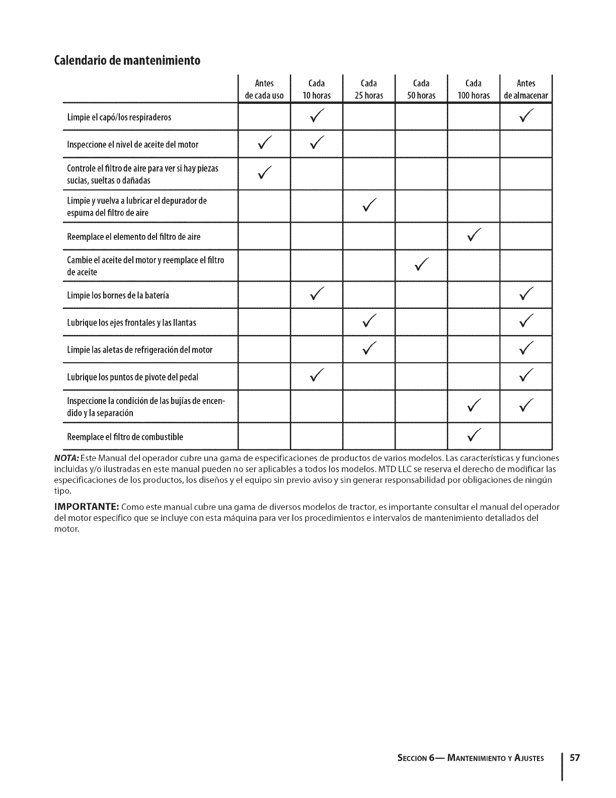
Calendario de mantenimiento
Antes
decadauso
Cada
10horas
Cada
25horas
Cada
50horas
Cada
100horas
Antes
dealmacenar
Limpieelcap6/iosrespiraderos _/ _/
Inspeccioneel nivel de aceitedel motor _/ _/
Controleel nitro de aire paraversihaypiezas _/
sudas,suekaso daffadas
Limpiey vuelvaa[ubricarel depuradorde V'"
espumadelfiltro deaire
Reemplacee[ eiemento del filtrode aire _/
Cambieel aceitedel motor y reemplacee[fikro VII
deaceite
Limpielosbornesde la bateria M/M/
Lubriquelosejesffontales y lasIlantas M/M/
Limpie[asaietasderefrigeraci6nde[motor V /V/
Lubriquelospuntosde pivotede[pedal M/M/
Inspeccionela condici6ndelasbujiasdeencen- _/ _/
dido yla separaci6n
Reemp[acee[ fiitro de combustible V /
NOTA: Este Manual del operador cubre una gama de especificaciones de productos de varios modelos. Las caracteristicas y funciones
incluidas y/o ilustradas en este manual pueden no set aplicables a todos los modelos. MTD LLC se reserva el derecho de modificar las
especificaciones de los productos, los diseffos y el equipo sin previo aviso y sin generar responsabilidad pot obligaciones de ningun
tipo.
IMPORTANTE: Como este manual cubre una gama de diversos modelos de tractor, es importante consultar el manual del operador
del motor especffico que se incluye con esta m_quina para ver los procedimientos e intervalos de mantenimiento detallados del
motor.
SECCiON 6-- MANTENiMIENTO Y AJUSTES 57
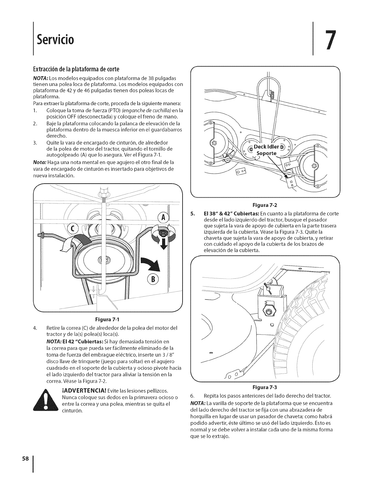
Servkio 7
E×tracd6ndela plataformadecorte
NOTA: Los modelos equipados con plataforma de 38 pulgadas
tienen una polea Ioca de plataforma. Los modelos equipados con
plataforma de 42 y de 46 pulgadas tienen dos poleas Iocas de
plataforma.
Para extraer la plataforma de corte, proceda de la siguiente manera:
1. Coloque la toma de fuerza (PTO) (enganche de cuchilla) en la
posici6n OFF (desconectada) y coloque el freno de mano.
2. Baje la plataforma colocando la palanca de elevaci6n de la
plataforma dentro de la muesca inferior en el guardabarros
derecho.
3. Quite la vara de encargado de cintur6n, de alrededor
de la polea de motor del tractor, quitando el tornillo de
autogolpeado (A) que Io asegura. Ver el Figura 7-1.
Nora: Haga una nota mental en que agujero el otro final de la
vara de encargado de cintur6n es insertado para objetivos de
nueva instalaci6n.
f
J
Figura 7-2
El 38" & 42" Cubiertas: En cuanto a la plataforma de corte
desde el lado izquierdo del tractor, busque el pasador
que sujeta la vara de apoyo de cubierta en la parte trasera
izquierda de la cubierta. V_ase la Figura 7-3. Quite la
chaveta que sujeta la vara de apoyo de cubierta,y retirar
con cuidado el apoyo de la cubierta de los brazos de
elevaci6n de la cubierta.
4_
Figura 7-1
Retire la correa (C) de alrededor de la polea del motor del
tractor y de la(s) polea(s)Ioca(s).
NOTA:E142 "Cubiertas: Si hay demasiada tensi6n en
la correa para que pueda ser f_cilmente eliminado de la
toma de fuerza del embrague el_ctrico, inserte un 3 /8"
disco Ilave de trinquete (juego para soltar) en el agujero
cuadrado en el soporte de la cubierta y ocioso pivote hacia
el lado izquierdo del tractor para aliviar la tensi6n en la
correa. V6ase la Figura 7-2.
iADVERTENCIA! Evite las lesiones pellizcos.
Nunca coloque sus dedos en la primavera ocioso o
entre la correa y una polea, mientras se quita el
cintur6n.
J
Figura 7-3
6. Repita los pasos anteriores del lado derecho del tractor.
NOTA: La varilla de soporte de la plataforma que se encuentra
del lado derecho del tractor se fija con una abrazadera de
horquilla en lugar de usar un pasador de chaveta; como habr_
podido advertir, _ste ultimo se us6 del lado izquierdo. Esto es
normal y se debe volver a instalar cada uno de la misma forma
que se Io extrajo.
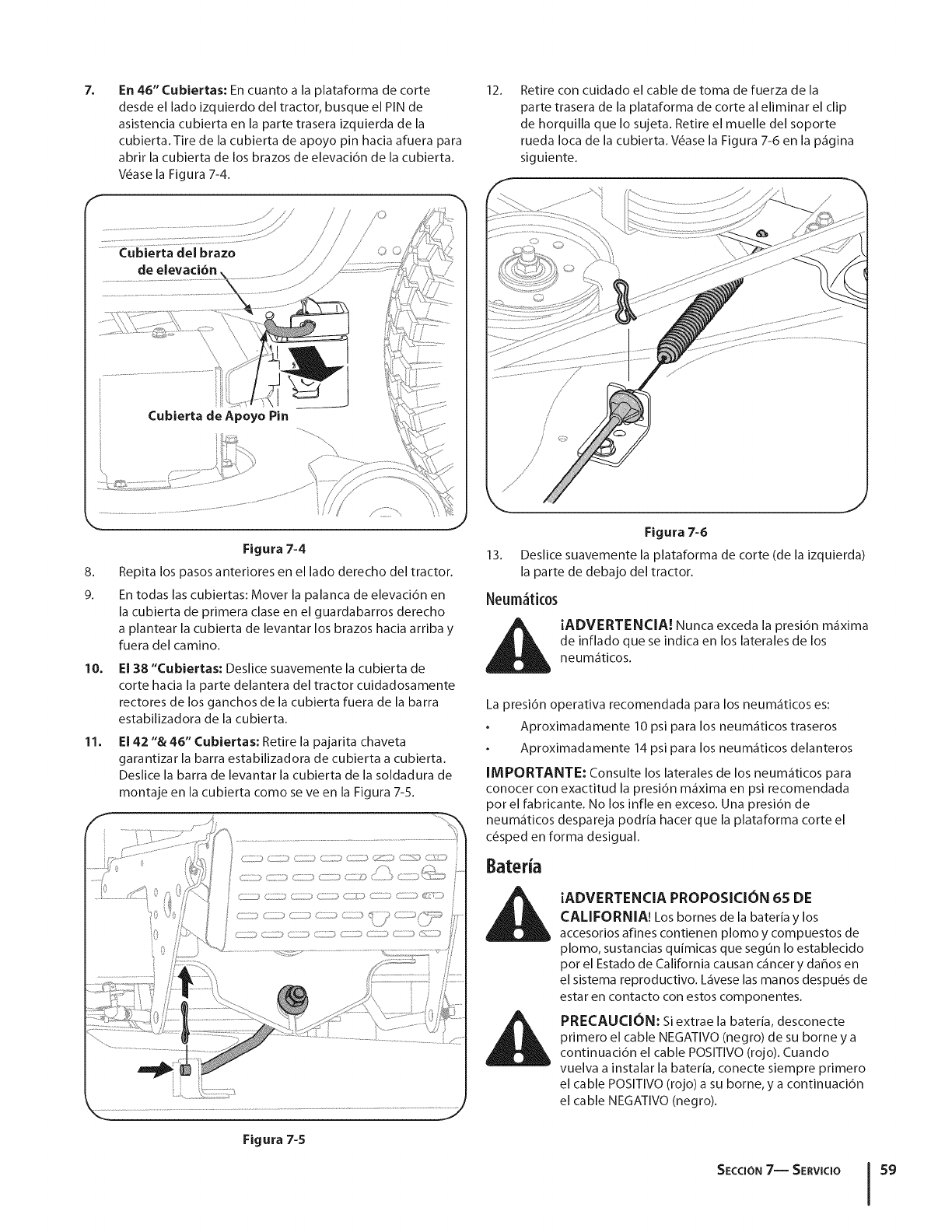
7,
F
En 46" Cubiertas: En cuanto a la plataforma de corte
desde el lado izquierdo del tractor, busque el PIN de
asistencia cubierta en la parte trasera izquierda de la
cubierta. Tire de la cubierta de apoyo pin hacia afuera para
abrir la cubierta de los brazos de elevaci6n de la cubierta.
Wase la Figura 7-4.
Cubierta clel braze
de elevaci6n,
©©
12. Retire con cuidado el cable de toma de fuerza de la
parte trasera de la plataforma de corte al eliminar el clip
de horquilla que Io sujeta. Retire el muelle del soporte
rueda Ioca de la cubierta. Wase la Figura 7-6 en la p_gina
siguiente.
Cubierta de Apeye Pin
.................................................................................................................
8.
9.
Figura 7=4
Repita los pasos anteriores en el lade derecho del tractor.
En todas las cubiertas: Mover la palanca de elevaci6n en
la cubierta de primera clase en el guardabarros derecho
a plantear la cubierta de levantar los brazes hacia arriba y
fuera del camino.
10. El 38 "Cubiertas: Deslice suavemente la cubierta de
corte hacia la parte delantera del tractor cuidadosamente
rectores de los ganchos de la cubierta fuera de la barra
estabilizadora de la cubierta.
11. El 42 "& 46" Cubiertas: Retire la pajarita chaveta
garantizar la barra estabilizadora de cubierta a cubierta.
Deslice la barra de levantar la cubierta de la soldadura de
montaje en la cubierta come se ve en la Figura 7-5.
Figura 7=6
13. Deslice suavemente la plataforma de corte (de la izquierda)
la parte de debajo del tractor.
Neum_tk0s
iADVERTENCIA! Nunca exceda la presi6n m_xima
de inflado que se indica en los laterales de los
neum_ticos.
La presi6n operativa recomendada para los neum_ticos es:
Aproximadamente 10 psi para los neum_ticos traseros
Aproximadamente 14 psi para los neum_ticos delanteros
IMPORTANTE: Consulte los laterales de los neum_ticos para
conocer con exactitud la presidn m_xima en psi recomendada
per el fabricante. No los infle en exceso. Una presidn de
neum_ticos despareja podria hacer que la plataforma corte el
c6sped en forma desigual.
iADVERTENCIA PROPOSICION 65 DE
CALIFORNIA! Los bornes de la bateHa y los
accesorios afines contienen plomo y compuestos de
plomo, sustancias qufmicas que segun Io establecido
per el Estado de California causan c_ncer y dahos en
el sistema reproductive. L_vese las manes despu_s de
estar en contacto con estos componentes.
PRECAUCION: Si extrae la bateria, desconecte
primero el cable NEGATIVO (negro) de su borne y a
continuaci6n el cable POSITIVO (rojo). Cuando
vuelva a instalar la bateria, conecte siempre primero
el cable POSITIVO (rojo) a su borne, y a continuacidn
el cable NEGATIVO (negro).
Figura 7-5
SECCION7-- SERVICIO 59
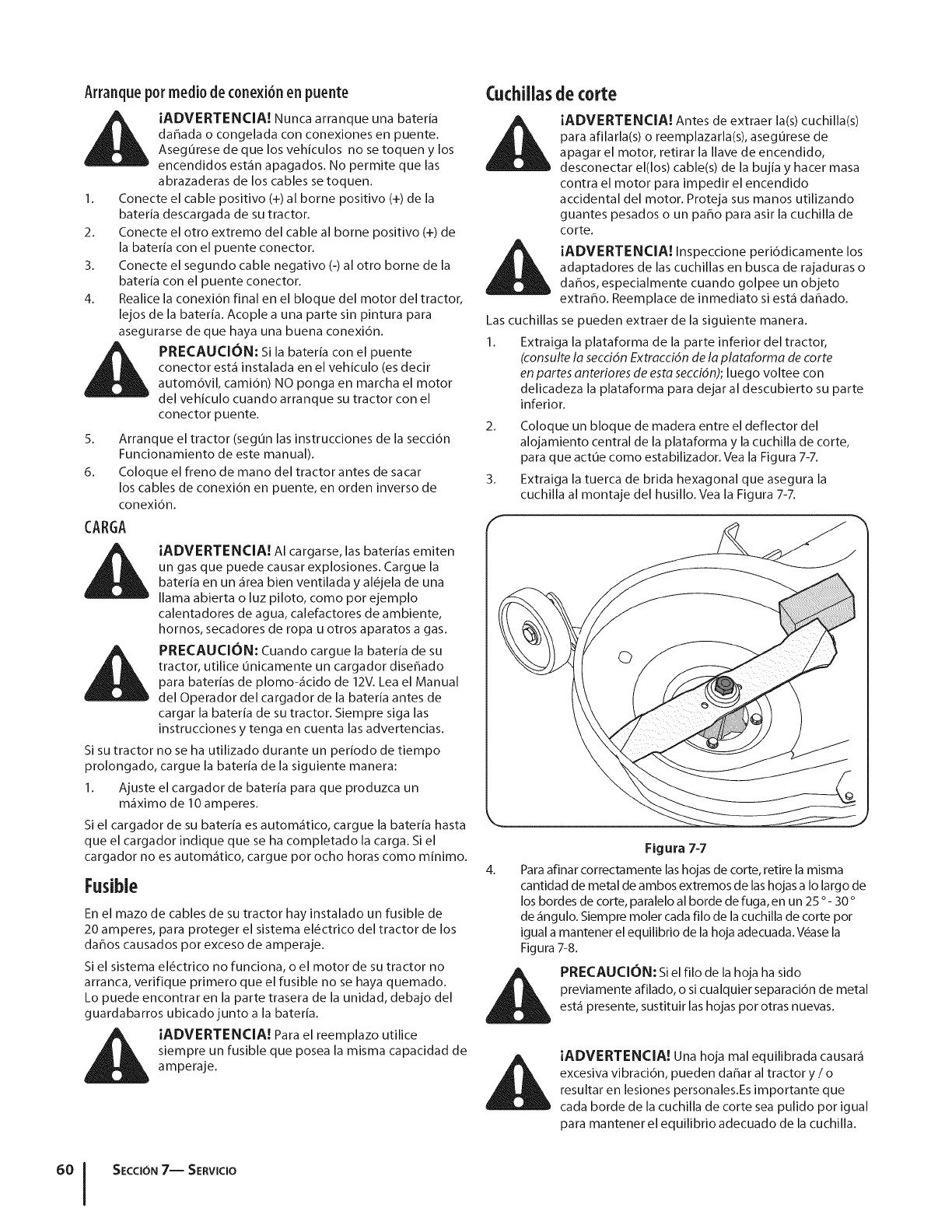
Arranquepotmedio deconexi6nen puente
iADVERTENCIA! Nunca arranque una bateria
daflada o congelada con conexiones en puente.
Aseg0rese de que los vehiculos no se toquen y los
encendidos est_n apagados. No permite que las
abrazaderas de los cables se toquen.
1. Conecte el cable positivo (+) al borne positivo (+) de la
bateria descargada de su tractor.
2. Conecte el otto extremo del cable al borne positivo (+) de
la baterfa con el puente conector.
3. Conecte el segundo cable negativo (=)al otto borne de la
baterfa con el puente conector.
4. Realice la conexi6n final en el bloque del motor del tractor,
lejos de la bateria. Acople a una parte sin pintura para
asegurarse de que haya una buena conexi6n.
PRECAUCION: Si la bateria con el puente
conector est_ instalada en el vehiculo (es decir
autom6vil, cami6n) NO ponga en marcha el motor
del vehiculo cuando arranque su tractor con el
conector puente.
5. Arranque el tractor (segun las instrucciones de la secci6n
Funcionamiento de este manual).
6. Coloque el freno de mano del tractor antes de sacar
los cables de conexi6n en puente, en orden inverso de
conexi6n.
CARGA
iADVERTENCIA! AI cargarse, las baterias emiten
un gas que puede causar explosiones. Cargue la
bateria en un _rea bien ventilada y al_jela de una
llama abierta o luz piloto, como pot ejemplo
calentadores de agua, calefactores de ambiente,
hornos, secadores de ropa u otros aparatos a gas.
PRECAUCION: Cuando cargue la bateria de su
tractor, utilice unicamente un cargador diseflado
para baterias de plomo-_cido de 12V. Lea el Manual
del Operador del cargador de la bateria antes de
cargar la bateria de su tractor. Siempre siga las
instrucciones y tenga en cuenta las advertencias.
Si su tractor no se ha utilizado durante un periodo de tiempo
prolongado, cargue la baterfa de la siguiente manera:
1. Ajuste el cargador de baterfa para que produzca un
m_ximo de 10 amperes.
Si el cargador de su bateria es autom_tico, cargue la baterfa hasta
que el cargador indique que se ha completado la carga. Si el
cargador no es autom_tico, cargue pot ocho horas como minimo.
Fusible
En el mazo de cables de su tractor hay instalado un fusible de
20 amperes, para proteger el sistema el_ctrico del tractor de los
daflos causados pot exceso de amperaje.
Si el sistema el_ctrico no funciona, o el motor de su tractor no
arranca, verifique primero que el fusible no se haya quemado.
Lo puede encontrar en la parte trasera de la unidad, debajo del
guardabarros ubicadojunto a la bateria.
i_ iADVERTENCIA! Para el reemplazo utilice
siempre un fusible que posea la misma capacidad de
amperaje.
CuchUlasde corte
IADVERTENCIA! Antes de extraer la(s) cuchilla(s)
para afilarla(s) o reemplazarla(s), asegurese de
apagar el motor, retirar la Ilave de encendido,
desconectar el(los) cable(s) de la bujia y hacer masa
contra el motor para impedir el encendido
accidental del motor. Proteja sus manos utilizando
guantes pesados o un patio para asir la cuchilla de
corte.
iADVERTENCIA! Inspeccione peri6dicamente los
adaptadores de las cuchillas en busca de rajaduras o
daflos, especialmente cuando golpee un objeto
extraflo. Reemplace de inmediato si est_ daflado.
Las cuchillas se pueden extraer de la siguiente manera.
1. Extraiga la plataforma de la parte inferior del tractor,
(consulte la secci6n Extracci6n de la platdorma de torte
en partes antedores de esta secci6n); luego voltee con
delicadeza la plataforma para dejar al descubierto su parte
inferior.
2. Coloque un bloque de madera entre el deflector del
alojamiento central de la plataforma y la cuchilla de corte,
para que actue como estabilizador. Vea la Figura 7-7.
3. Extraiga la tuerca de brida hexagonal que asegura la
cuchilla al montaje del husillo. Vea la Figura 7-7.
Figura 7=7
4. Para afinar correctamente las hojas de corte, retire la misma
cantidad de metal de ambos extremos de las hojas a Io largo de
los bordes de corte, paralelo al borde de fuga, en un 25 °- 30 °
de _ngulo. Siempre moler cada filo de la cuchilla de corte pot
igual a mantener el equilibrio de la hoja adecuada.Wase la
Figura 7-8.
PRECAUCIC)N:Si el filo de la hoja ha sido
previamente afilado, o si cualquier separaci6n de metal
est_ presente, sustituir las hojas pot otras nuevas.
_L ADVERTENCIA! Una hoja mal equilibrada causar_
excesiva vibraci6n, pueden daflar al tractor y /o
resultar en lesiones personales.Es importante que
cada borde de la cuchilla de corte sea pulido pot igual
para mantener el equilibrio adecuado de la cuchilla.
°°1
SECCION7-- SERVlCIO
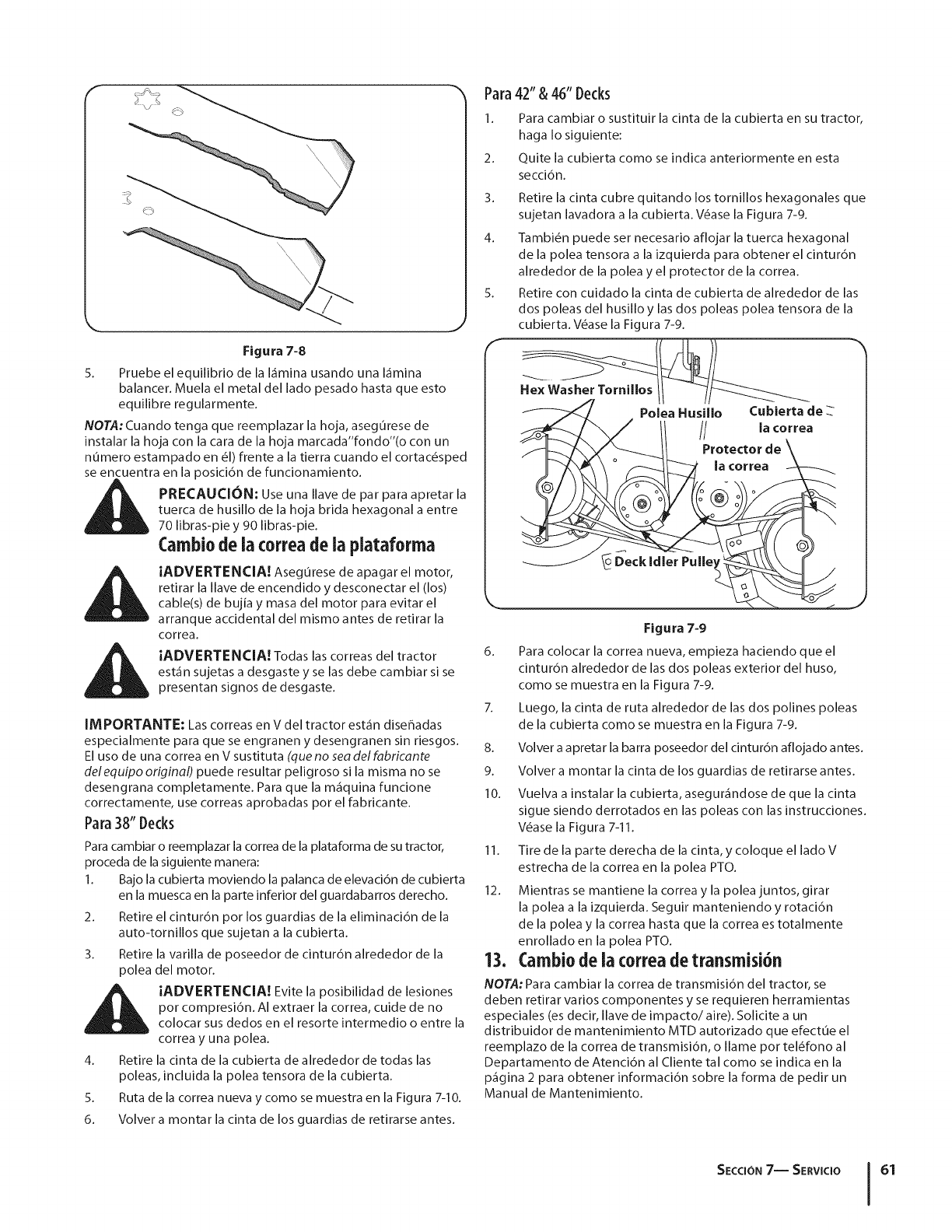
F
\\
Figura 7-8
5. Pruebe el equilibrio de la I_mina usando una I_mina
balancer. Muela el metal del lado pesado hasta que esto
equilibre regularmente.
NOTA: Cuando tenga que reemplazar la hoja, aseg0rese de
instalar la hoja con la cara de la hoja marcada"fondo"(o con un
numero estampado en 61)frente a la tierra cuando el cortac_sped
se encuentra en la posici6n de funcionamiento.
PRECAUCION: Use una Ilave de par para apretar la
tuerca de husillo de la hoja brida hexagonal a entre
70 libras-pie y 90 libras-pie.
Cambiode ia correade ia plataforma
iADVERTENClA! Aseg0rese de apagar el motor,
retirar la Ilave de encendido y desconectar el (los)
cable(s) de bujia y masa del motor para evitar el
arranque accidental del mismo antes de retirar la
correa.
iADVERTENClA! Todas las correas del tractor
est_n sujetas a desgaste y se las debe cambiar si se
presentan signos de desgaste.
IMPORTANTE: Las correas en V del tractor est_n diserqadas
especialmente para que se engranen y desengranen sin riesgos.
El uso de una correa en V sustituta (clue no sea del fabricante
delequipo original) puede resultar peligroso si la misma no se
desengrana completamente. Para que la m_quina funcione
correctamente, use correas aprobadas pot el fabricante.
Para38" Decks
Para cambiar o reemplazar la correa de la plataforma de su tractor,
proceda de la siguiente manera:
1. Bajo la cubierta moviendo la palanca de elevaci6n de cubierta
en la muesca en la parte inferior del guardabarros derecho.
2. Retire el cintur6n pot los guardias de la eliminaci6n de la
auto-tornillos que sujetan a la cubierta.
3. Retire la varilla de poseedor de cintur6n alrededor de la
polea del motor.
iADVERTENClA! Evite la posibilidad de lesiones
pot compresi6n. AI extraer la correa, cuide de no
colocar sus dedos en el resorte intermedio o entre la
correa y una polea.
4. Retire la cinta de la cubierta de alrededor de todas las
poleas, incluida la polea tensora de la cubierta.
5. Ruta de la correa nueva y como se muestra en la Figura 7-10.
6. Volver a montar la cinta de los guardias de retirarse antes.
Para
I.
2.
3.
4.
42" & 46" Decks
Para cambiar o sustituir la cinta de la cubierta en su tractor,
haga Io siguiente:
Quite la cubierta como se indica anteriormente en esta
secci6n.
Retire la cinta cubre quitando los tornillos hexagonales que
sujetan lavadora a la cubierta. V_ase la Figura 7-9.
Tambi_n puede set necesario aflojar la tuerca hexagonal
de la polea tensora a la izquierda para obtener el cintur6n
alrededor de la polea y el protector de la correa.
Retire con cuidado la cinta de cubierta de alrededor de las
dos poleas del husillo y las dos poleas polea tensora de la
cubierta. V_ase la Figura 7-9.
Polea Husillo Cubierta de
// la correa
Protector
Deck Idler Pulley
Figura 7-9
6. Para colocar la correa nueva, empieza haciendo que el
cintur6n alrededor de las dos poleas exterior del huso,
como se muestra en la Figura 7-9.
7. Luego, la cinta de ruta alrededor de las dos polines poleas
de la cubierta como se muestra en la Figura 7-9.
8. Volver a apretar la barra poseedor del cintur6n aflojado antes.
9. Volver a montar la cinta de los guardias de retirarse antes.
10. Vuelva a instalar la cubierta, asegur_ndose de que la cinta
sigue siendo derrotados en las poleas con las instrucciones.
V6ase la Figura 7-11.
11. Tire de la parte derecha de la cinta, y coloque el lado V
estrecha de la correa en la polea PTO.
12. Mientras se mantiene la correa y la polea juntos, girar
la polea a la izquierda. Seguir manteniendo y rotaci6n
de la polea y la correa hasta que la correa es totalmente
enrollado en la polea PTO.
13. Cambiode ia correa detransmisi6n
NOTA: Para cambiar la correa de transmisi6n del tractor, se
deben retirar varios componentes y se requieren herramientas
especiales (es decir, Ilave de impacto/aire). Solicite a un
distribuidor de mantenimiento MTD autorizado que efectue el
reemplazo de la correa de transmisi6n, o Ilame pot tel6fono al
Departamento de Atenci6n al Cliente tal como se indica en la
p_gina 2 para obtener informaci6n sobre la forma de pedir un
Manual de Mantenimiento.
SECCION7-- SERVlCIO 61
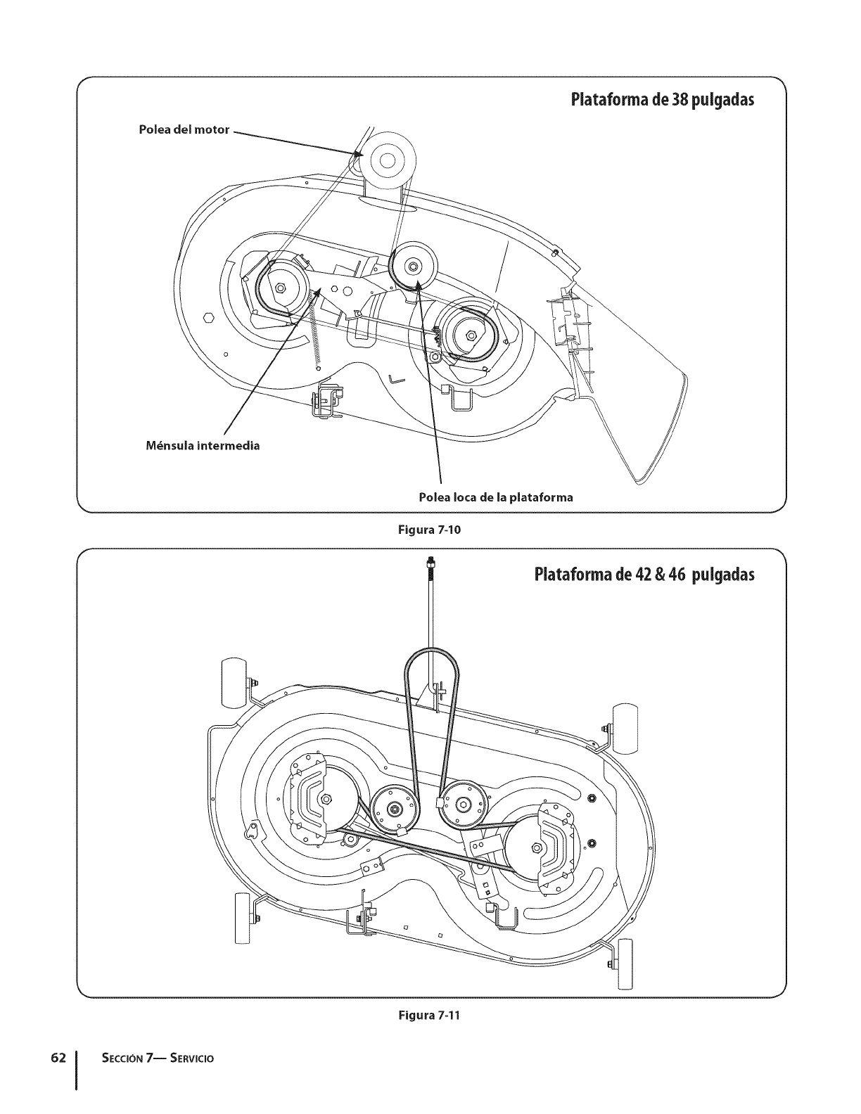
F
Polea del motor
Plataformade38 pulgadas
©
M_nsula intermedia
Figura 7-10
Plataformade42 & 46 pulgadas
Figura 7-11
SECCION7-- SERVICIO
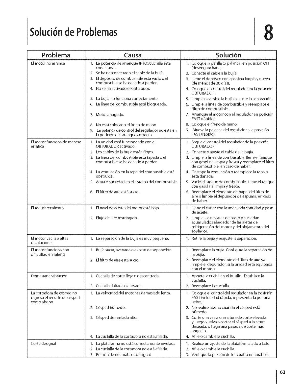
Soluci6nde Problemas
Problema
El motor no arranca
2.
3.
4.
5.
6.
El motor funclona de manera
errAtlca
El motor recahenta
Causa
La potencla de arranque (PTO)!cuchilla est.1
conectada.
Se ha desconectado el cable de la bujia.
Eldep6sJto de combustible est.1ratio o el
combustible se ha echado a perder.
No se ha activado el obturador.
Soluci6n
El motor vaclla a altas
revo[uciones
El motor funciona con
dlflcultad en ralenti
Oemaslada vlbracl6n
La cortadora de c6sped no
regresa el recorte de c_sped
como abono
Corte des,gua[
La bujia no funciona correctamente.
La linea del combustible est& bloqueada.
Motorahogado.
8. No estg colocado el freno de mano
9. La palanca de control del regulador no est.1 en
la posicl6n de arranque correcta.
1. La umdad est_qfunclonando con el
OBTURADOR actwado.
2. Los cables de la bujia esta'n flojos.
3. La linea del combustible esta"tapada o el
combustible se ha echado a perder.
4.
5.
6.
La ventllacl6n en la tapa del combustible estA
obstrulda.
Agua o sucledad en el slstema del combustible.
Elflltro de alre est,1suclo.
1. El nlvel de acelte del motor est.1 bajo.
2. Flujo de a,re restrJngldo.
1. La separacl6n de la bujia es muy pequeffa.
1. Bujia sucla, averlada o exceso de separaci6n.
2. Elflltro de aire est,1sucio.
1. CucMla de corte floja o descentrada.
2. CucMla daffada o curvada.
1. La velocldad del motor es demasiado lenta.
2. C_sped humedo.
3. C6sped demasiadoalto.
4. La cuchdla de la cortadora no est,1afllada.
1. La plataforma no estA correctamente nwelada.
2. La cucMla de la cortadora no est,1afllada.
3. Pres,6n de neum_qtlcosdeslgual.
1, Coloque la perilia (o palanca) en posicl6n OFF
(desenganchada).
2. Conecte el cable a la bujia.
3. Llene el dep6slto con gasohna hmpia y nueva
(de menos de 30 dias).
4. Coloque el control del regulador en la poslcl6n
OBTURADOR.
5. Limple o camble la bujia o ajuste la separac,6n.
6. LimpJe la linea de combustible y reemplace el
filtro de combustible.
7. Arranque el motor con el regulador en posJcl6n
FAST (ra"pido).
8. Coloque el freno de mano.
9. Mueva la palanca del reguladora la poslcl6n
FAST (r_ipldo).
1. Saque el control del regulador de la poslcl6n
OBTURADOR.
2. Conecte y ajuste el cable de la bujia.
3. Dmple la Iinea de combustible; [[ene el tanque
con gasohna hmDa y fresca y reemplace el flltro
de combustible, en caso de haber.
4. Destape la ventllacl6n o reemplace la tapa s,
esta" dafiada.
5. Vacie el tanque de combust,ble. Llene el tanque
con gasohna hmpla y fresca.
6. Reemp[ace el elemento de papel de[ flltro de
alre o hmple el depurador de espuma, en caso
de haber.
1,
2.
1.
1.
2.
1.
2.
1.
2,
3.
4.
1.
2.
3.
Llene el c,4rter con la adecuada cantldad y peso
de aceite.
Llmple los recortes de pasto y sucledad
acumulados alrededor de las aletas de
refrigeraci6n del motor y del alojamlento del
soplador.
Retire la bujia y reajuste la separacl6n.
Reemplace la bujia. Configure la separacl6n de
la bujia.
Reemplace el elemento del filtro de alre y/o
limpie el depurador, sl la umdad est.] equipada
con el mismo.
Aprlete [a cucMla yel husdlo. Establhce la
cuchllla.
Reemplace la cuchllla.
Coloque el control del regulador en la posici6n
FAST (velocidad rAplda, representada por una
hebre).
No reahce abono cuando el c_sped est,1
hOmedo.
Corte una vez a una altura de corte elevada
y luego vuelva a cortar el c_sped a la altura
deseada, o haga una pasada de corte m_qs
angosta.
Afile o camble la cuchllla.
Reahce un ajuste de la plataforma lado a lado.
Aflle o camble la cucMla.
Venflque la presl6n de los cuatro neum_itlcos.
63

Piezasde reemplazo 9
Lacorreade transmisi6n(Plataformadecorte)38 "Deck
Lacorreade transmisi6n(Plataformadecorte)42 "Deck
Lacorreade transmisi6n(Plataformadecorte)46 "Deck
HojadeCubierta(38 "Deck)
HojadeCubierta(42"Deck)
ExtremoHojadeCubierta(42 "Deck)
954-04062
954-04060B
954-04219
942-0610A
942-04308
942-04308-X
HojadeCubierta(46 "Deck) 942-04290
ExtremoHojadeCubierta(46 "Deck) 942-04290-X
Cubiertadel husillo(38 "Deck) 918-04474A
Cubiertadel husillo(42 "Deck) 918-04822A
Cubiertadel husillo(46 "Deck) 918-04636A
Cubiertade la rueda(posterior) 734-0973
Cubiertade la rueda(delantera-42" &46 "Deck) 734-04155
Bateria 925-1707D
Tire (frontal)15x 6 x 6 Rondadehombro 734-04240A
Tire (frontal)15x 6 x 6 Plazade hombro 734-1731
Tire (Rear)20 x 8 x 8 de la Rondade hombro 734-04241
Tire (Rear)20 x 8 x 8 Plazahombro 734-1730
HubCap 731-0484A
Deltanquede combustibleCap 951-12179A
Deltanquede combustibleCap(CA Modelos) 951-12426
Controldel acelerador/ChokeCable(Singlecilindrosen) 746-04367
Tolvadedescargadela Asamblea38 "Deck 931-1032B
Tolvadedescargadela Asamblea42" Deck 631-04288
Tolvadedescargadela Asamblea46" Deck 631-04288
N_mero 925-1745A
NOTA: Este Manual del operador cubre una gama de especificaciones de productos de varios modelos. Las caracteristicas y funciones
incluidas y/o ilustradas en este manual pueden no set aplicables a todos los modelos. MTD LLC se reserva el derecho de modificar las
especificaciones de los productos, los diseSos y el equipo sin previo aviso y sin generar responsabilidad pot obligaciones de ningun
tipo.
NOTA: Descargue un Manual de Piezas de Repuesto completo sin cargo en www.mtdproducts.com o comuniquese pot tel_fono
al (800) 800-7310 para comprar un Manual de Piezas de Repuesto. Asegurese de tenet a mano el numero de modelo y el numero
de serie. Esta informaci6n se encuentra en la placa de modelo ubicada debajo del asiento. Consulte la p_gina 2 para obtener m_s
informaci6n sobre la ubicaci6n de sus numeros de modelo y de serie.
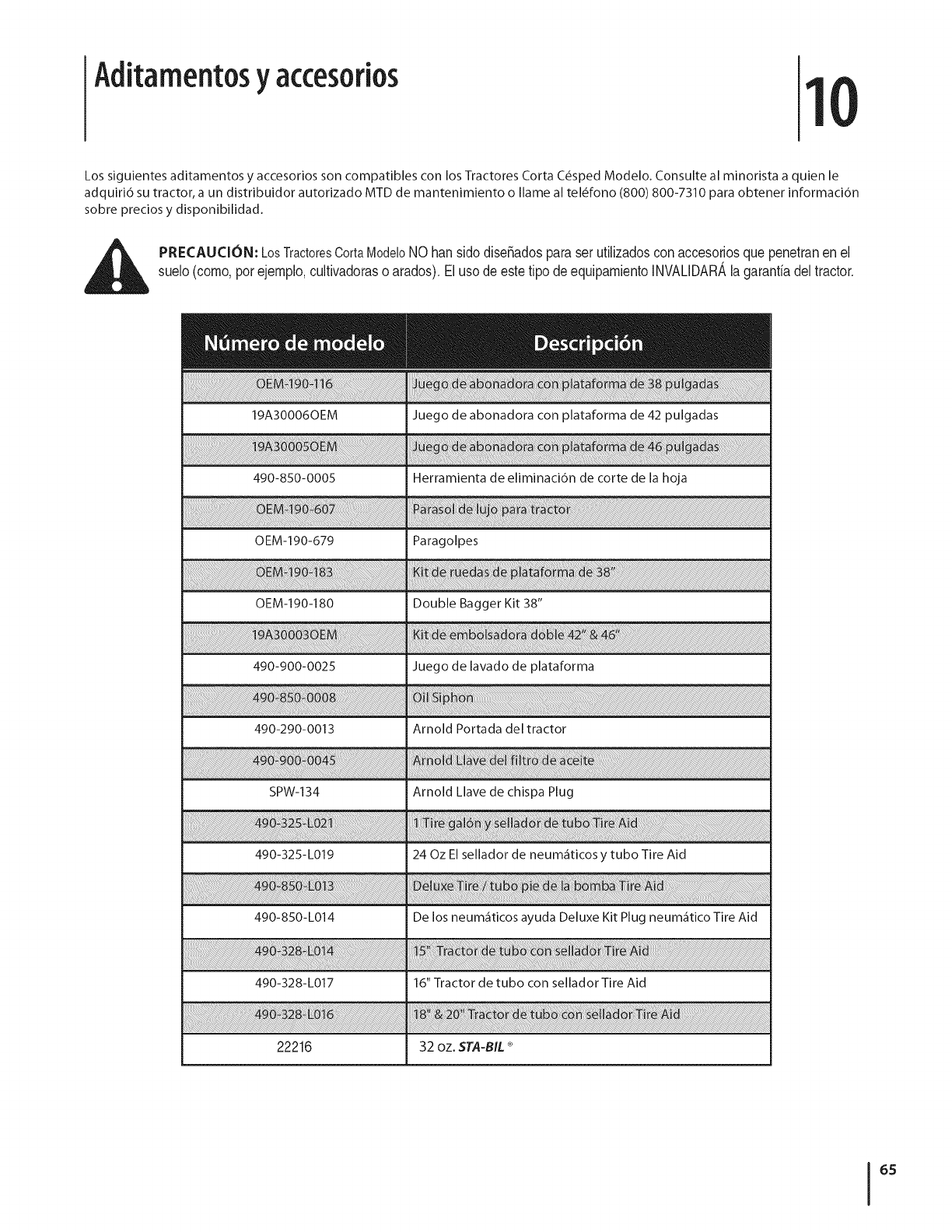
Aditamentosy accesorios 1
Los siguientes aditamentos y accesorios son compatibles con los Tractores Corta C_sped Modelo. Consulte al minorista a quien le
adquiri6 su tractor, a un distribuidor autorizado MTD de mantenimiento o Ilame al tel_fono (800) 800-7310 para obtener informaci6n
sobre precios y disponibilidad.
PRECAUCION: LosTractoresCortaModeloNOhansidodisefiadosparaser utilizadosconaccesoriosquepenetranen el
suelo(como,porejemplo,cultivadoraso arados).Eluso deestetipo deequipamientoINVAUDARAlagarantiadeltractor.
490-850-0005 Herramienta de eliminaci6n de corte de la hoja
OEM-190-679 Paragolpes
_ fo _ _
OEM-190-180 Double Bagger Kit 38"
490-900-0025 Juego de lavado de plataforma
6iii
490-290-0013 Arnold Portada del tractor
490-328-L017 16" Tractor de tubo con sellador Tire Aid
22216 32 oz. STA-B_L®
65
DECLARACIONFEDERALy/oDECALIFORNIASOBRE GARANTJAS EN EL CONTROL DE EIVIISIONES
SUS DERECHOS Y OBLIGACIONES EN CUANTO A LA GARANTJA
MTDConsumerGroupInc,laAgenciadeProtecci6nMedioambientaldelos EstadosUnidos(EPA),y paraaquellosproductoscertificadosparasu ventaen el es-
tadode California,el Departamentode los Recursosdel Aire deCalifornia(CARB)secomplacenenexplicarla garanfiaque cubreal sistemade control(ECS)de
emisiones(evaporativasy/o de escape)de su equipoy motor(motordeequiposdeexteriores)deencendidopot chispaparatodo terreno,peque_o,deexteriores
del a_o2006 y a_osposterioresEn California,losnuevosmotoresde equiposdeexterioresdebenestar dise_ados,construidosyequipadosparacumplircon las
estrictasnormasantipoluci6ndel Estado(en otrosestados,losequiposdel a_o 1997y modelosposterioresdebenserestar dise_ados,construidosy equipados
paracumplircon las regulacionesdemotoresdeencendidopor chispaparatodoterrenopeque_osde laAgenciade Protecci6nMedioambientalde los Estados
Unidos,(EPA).MTDConsumerGroupInc.debe garantizarel sistemade controldeemisiones(ECS) desu motordeequiposde exteriorespot el periodode
tiempoindicadom_sabajo,siempreycuando noexistausoincorrecto,negligenciao mantenimientoinadecuadodedicho motor.
SuECSpuedeincluirpiezastalescomo el carburador,el sistemade inyecci6nde combustible,el sistemadeencendido,el convertidorcatalitico,losdep6sitos
decombustible,laslineasdecombustible,lostaponesde combustible,lasv_lvulas,contenedores,filtros, manguerasdevapor,abrazaderas,conectoresyotros
componentesafinesrelacionadoscon lasemisiones.
Dondeexistaunacondici6ncubiertapor la garantia,MTDConsumerGroupInc.reparar_su motorde equiposde exterioressincostoalgunoincluyendoel
diagn6stico,las piezasy la manodeobra.
COBERTURA DE LA GARANTJA DEL FABRICANTE:
Estesistemadecontroldeemisionesse garantizaporel t@minode dos aSos.Si algunapiezarelacionadacon lasemisionesdesu motorde equiposde
exterioreses defectuosa,MTDCONSUMERGROUPINC.reparar_o sustituir_dichapieza.
RESPONSABILIDADES DEL PROPIETARIO SEGUN LA GARANTJA:
Ensu car_cterdepropietariodel motordeequiposdeexteriores,usted es responsabledel mantenimientorequeridoquese especificaenel manualdel propieta-
rio.MTDConsumerGroupInc le recomiendaque conservetodos losrecibos quecubrenel mantenimientode su motor,no obstanteIo cual MTDConsumerGroup
Inc nopodr_denegarel cumplimientode lagarantiaQnicamentepor lafaltade los recibos.
Comopropietariodel motordeequiposde exteriores,usteddebe saberqueMTDConsumerGroupInc.puededenegarlacoberturade lagarantia si su motoro
unapiezadel mismofallandebidoa uso incorrecto,negligencia,mantenimientoindebidoo a modificacionesno aprobadas.
Ustedes responsablede presentarsu motoral centrode distribuci6no serviciotecnico deMTDConsumerGroupInc.tan prontocomo aparezcael problema.Las
reparacionescubiertaspor la garantiase debenIlevara caboen unlapsorazonableque no excedade 30 dias.Sitiene algunapreguntarespectode lacobertura
dela garantia,p6ngaseen contactoconel Departamentodel ServicioT@nicode MTDConsumerGroupInc.al telefono1-800-800-7310o pot correoelectr6nico
enhttp://support.mtdproducts.com
COBERTURA DE LA GARANTJA DE EMISIONES GENERALES:
MTDConsumerGroupIncgarantizaal compradorfinaly a cadacompradorsubsiguienteque el motordeequiposde exteriores:est_ dise_ado,construidoy
equipadode mododecumplircontodas las regulacionesaplicablesy quese encuentralibrededefectosdematerialesyde fabricaci6nque pudierencausarla
falla deuna piezagarantizadaidentica,entodos losaspectosmaterialesa la piezadescriptaenla solicitudde certificaci6ndeMTDConsumerGroupInc.
El periododegarantiacomienzaenla fechade entregadel motoral compradorfinalo en lafechaen que la m_quinase poneen funcionamientopot primeravez.
El periodode garantiaes de dos aSos.
Sujetoa ciertas condicionesyexclusionesquese indicana continuaci6n,lagarantiadelas piezasrelacionadascon lasemisioneses la siguiente:
1. Cualquierpiezagarantizadaque no esteprogramadaparaserreemplazadacomo partedel mantenimientorequeridoen lasinstruccionesescritassuminis-
tradasse garantizaporel periodo de garantiaarriba mencionado.Sila piezafalladuranteel periodo decoberturade lagarantia,la mismaser_ reparada
o reemplazadaporMTDConsumerGroupInc.deacuerdo conel parrafo(4)a continuaci6n.Cualquierpiezareparadao reemplazadasegQnlagaranfiase
garantizar_potel resto del periodode garantia.
2. Cualquierpiezagarantizadaqueeste programadasolamenteparainspecci6nregularenlas instruccionesescritassuministradassegarantizapotel periodo
degarantiaarribamencionado.Cualquierpiezareparadao reemplazadasegQnla garantiase garantizar_pot el restodel periodo.
3. Cualquierpiezagarantizadaqueeste programadapara reemplazosegL]nel mantenimientorequeridode conformidadcon lasinstruccionesescritassuminis-
tradas,se garantizaporel periododetiempoanteriora laprimerafecha de reemplazoprogramadapara esapieza.Si la piezafalla antes del primerreemplazo
programatic,la mismaser&reparadao reemplazadapot MTDConsumerGroupInc.de acuerdoconel parrafo(4)a continuaci6n.Cualquierpiezareparadao
reemplazadabajogarantiase garantizar_potel resto del periodoanterioral primerreemplazoprogramaticpuntualparaesa pieza.
4. Lareparaci6no el reemplazodecualquierpiezagarantizadade conformidadconlasdisposicionesde lagarantiaqueaquise estipulase deben realizarenun
centrodegarantiasin costoalgunoparael propietario.
5. Noobstantelas disposicionesque aquise estipulan,losservicioso reparacionesbajo garantiase suministrar_nentodos nuestroscentrosdedistribuci6nbajo
franquiciademantenimientoparalos motoreso equiposencuesti6n.
6. El propietariodel motorde equiposdeexterioresno deber_pagarel trabajodediagn6sticodirectamenteasociadocon unapiezagarantizadadefectuosaen
relaci6nconlas emisiones,siempreycuandodichotrabajode diagn6sticose realiceen un centrocubiertopot lagarantia.
7. MTDConsumerGroupInces responsablepotdaSoscausadosa otroscomponentesdemotoreso equiposderivadosde lafalla bajo garantiade cualquier
piezagarantizada.
8. Durantelatotalidaddelperiododegarantiadelmotoryequipoparatodoterrenoarribamencionado,MTDConsumerGroupIncmantendr_unsuministro
depiezasbajogarantiasuficienteparasatisfacerlademandaesperadadetalespiezas.
9. Cualquierpiezadereemplazosepodr_usarparaelcumplimientodelmantenimientoolasreparacionesbajogarantiaysesuministrar_nsincargopara
elpropietario.Dichousonoreducir_lasobligacionesdegarantiadeMTDConsumerGroupInc.
10.Nosepodr_nusarpiezasadicionalesnimodificadasquenoestenexentasdeacuerdoconelDepartamentodelosRecursosdelAire(AirResourcesBoard).
Elusodecualquierpiezaadicionalomodificadanoexentaporelcompradorfinalser_causaldeinvalidezdelosreclamosbajogaranfia.MTDConsumer
GroupIncnotendr_responsabilidadpotlagarantiadefallasdepiezasgarantizadasquefuerencausadaspotelusodeunapiezaadicionalnoexenta
omodificada.
PIEZAS GARANTIZADAS:
Lareparaci6no el reemplazodecualquierpiezagarantizadaquede otto modopudieseestar cubiertapor lagarantia podr_set excluidadetal coberturade
garantiasi MTDConsumerGroupIncdemuestraqueel motores objeto deusoincorrecto,negligenciao mantenimientoinadecuado,y que tal usoincorrecto,
negligenciao mantenimientoinadecuadofuecausa directade la necesidadde reparaci6no reemplazode dichapieza.NoobstanteIo antedicho,cualquierajuste
de uncomponenteconun dispositivodelimitaci6nde ajusteinstaladoen f_bricay quefuncioneadecuadamente,podr_set cubiertopot la garantia.Adem_s,
la coberturabajoestagarantiase extiendesolo a piezasqueestuvieronpresentesenel motory equipotodo terrenoadquiridos.
Est_ncubiertaslas siguientespiezascongaranfiaparaemisiones(decorresponder):
(1)Sistemademedici6nde combustible
• Sistemade mejoraparainicioenfrio (cebadosuave)
• Carburadory piezasinternas(osistemade inyecci6npotcombustible)
• Bombade combustible
• Dep6sitodecombustible
(2)Sistemade inducci6ndeaire
• Purificadordeaire
• Colectordeadmisi6n
(3) Sistemadeencendido
• Bujia(s) deencendido
• Sistemade encendidopot magneto
(4)Sistemade encendido
• Convertidorcatalitico
,, SAI(v_lvula Reed)
(5)Componentesvariosutilizadosen el sistemaanterior
• Wlvulas e interruptoresde vacio,temperatura,posici6nsensiblesal tiempo
• Conectoresy montajes
(6) Controlevaporativo
• Manguerade combustible
• Abrazaderasde la manguerade combustible
• Tap6ndel combustibleatadopot correa
• Cajadecarbono
• Lineas de vapor
GDOC-100223
GARANT|A LIMITADA DEL FABRICANTE
La siguiente garantia limitada es otorgada per MTD LLC con
respecto a nuevos productos adquiridos y utilizados en Estados
Unidosy/o sus territories y posesiones, y per MTD Products Limited
con respecto a nuevos productos adquiridos y utilizados en Canad_i
y/o sus territories y posesiones (cualquiera de las dos entidades,
respectivamente, "MTD").
Esta garantia es adicional a la garantia de emisiones aplicables
proporcionada con el producto.
"MTD" garantiza este producto (excluidas las PiezasyAccesorios
con Desgaste Normal segdn se describe m_is abajo) contra
defectos en los materiales y mane de obra per un periodo de
dos (2) a_os a partir de la fecha de compra original y, a su opci6n,
reparar_i o reemplazar_i, sin costo alguno, cualquier pieza que
presente defectos en los materiales o de mane de obra. Esta
garantia limitada s61o se aplicar_i si el producto ha side operado
y mantenido de acuerdo con las instrucciones del Manual del
Operador que se proporciona con el producto y no ha side objeto
de use inapropiado, abuse, use comercial, abandono, accidente,
mantenimiento incorrecto, alteraci6n, vandalismo, robe, incendio,
inundaci6n o algun da_o debido a otto peligro o desastre natural.
El daho resultante per la instalaci6n o el use de piezas, accesorios
o aditamentos no aprobados per MTD para su use con el(los)
producto(s) incluido(s) en este manual anular_i la garantia en Io que
respecta a esos dahos.
Se garantiza que las Piezas con Desgaste Normal est_n libres de
defectos en los materiales y mane de obra per un periodo de
treinta (30) dias a partir de la fecha de compra. Las piezas sujetas
a desgaste normal incluyen pero no se limitan a: baterias, correas,
cuchillas, adaptadores para cuchillas, dientes, bolsas para paste,
ruedas, ruedas para la plataforma de la podadora tractor, asientos,
zapatas antideslizantes, ruedas de fricci6n, placas de raspado,
gomas helicoidales y neum_iticos.
Accesonos -- MTD garantiza que los accesorios de este producto
est_in libres de defectos de material y mane de obra durante
un periodo de un (1)abe a partir de la fecha de compra o
arrendamiento original del accesorio. Los accesorios incluyen, pete
no se limitan a: colectores de c_sped y kits para abono.
C6MO SOLICITAR fOBTENER SERVIClO TECNICO: El servicio
de la garantia est_i disponible, CON COMPROBANTE DE COMPRA, a
trav_s de su distribuidor local de servicio autorizado. Para Iocalizar
el distribuidor en su _irea:
En Estados Unidos de America
Consulte las p_iginas amarillas, o p6ngase en contacto con MTD LLC
en P.O.Box 361131, Cleveland, Ohio 44136-0019, Ilame al 1-800-800-
7310, o visite nuestro sitio web en www.mtdproducts.com.
En Canad_
Contacte MTD Products Limited, Kitchener, ON N2G 4J1, Ilame al
1-800-668-1238 o visite nuestro sitio web en www.mtdcanada.com.
Esta garantia limitada no ofrece cobertura en los siguientes cases:
a. El motor o las piezas que Io componen. Estos productos
pueden tenet garantia del fabricante per separado. Consulte
los t_rminos y condiciones de la garantia aplicable del
fabricante.
b. Las bombas rompetroncos, wilvulas y cilindros tienen una
garantia separada de un abe.
c. Los articulos necesarios para el mantenimiento de rutina
come per ejemplo lubricantes, filtros, afiladores de cuchillas,
sincronizaci6n del motor, los ajustes de los frenos, del
embrague o de la plataforma y el deterioro normal del
acabado exterior debido al use o exposici6n.
d. Mantenimiento no realizado per el distribuidor de servicio
autorizado.
e. MTD no extiende ninguna garantia para los productos
vendidos o exportados fuera de los Estados Unidos de
Am6rica y/o Canad_i, y sus respectivas posesiones y territories,
excepto para aquellos vendidos a trav6s de los canales
autorizados de distribuci6n de exportaciones de MTD.
fi Piezas de reemplazo que no son piezas originales de MTD.
g. Gastos de tra nsporte y per visitas t_cnicas.
h. MTD no garantiza este producto para use comercial.
No se aplican garantias implicitas, incluidas las garantias
implicitas de comerciabilidad o de adecuaci6n para un
prop6sito determinado, despu_s del periodo de aplicaci6n
de la garantia escrita expresa e×tendida m_s arriba para
las piezas de acuerdo con su identificaci6n. Ninguna otra
garantia expresa, ni oral ni escrita, e×cepto la mencionada
anteriormente, extendida per personas reales o juridicas,
incluidos los distribuidores o los minoristas con respecto a
cualquier producto, obligar_ a MTD. Durante el plazo de la
garantia el _lnico recurso es la reparaci6n oreemplazo del
producto come se indic6 anteriormente.
Las disposiciones incluidas en esta garantia proveen el
recurso _nico ye×clusivo que surge de las ventas. MTD no
se har_ responsable de ninguna p_rdida oda_o incidental o
resultante, incluyendo sin limitaci6n, los gastos incurridos
para los servicios de mantenimiento del paste, o los gastos
de arrendamiento para reemplazar de manera transitoria un
producto bajo garantia.
Algunos estados no permiten la exclusi6n o limitaci6n de los
dahos y perjuicios incidentales o directos, o las limitaciones sobre
la duraci6n de las garantias implicitas, per Io que las exclusiones
o limitaciones mencionadas anteriormente pueden no serle de
aplicaci6n.
En ningun case se obtendr_i una compensaci6n mayor al monte
del precio de compra del producto vendido. La alteraci6n de
las caracteristicas de seguridad del producto anular_ esta
garantia. Usted asume el riesgo y la responsabilidad de las
p_rdidas, dahos o lesiones que sultan usted y sus bienes y /o otras
personas y sus bienes come resultado del use incorrecto o de la
falta de capacidad para usar este producto.
Esta garantia limitada alcanza solamente al comprador original, o a
la persona que recibi6 el producto de regale.
COMe SE RELAClONA LA LEGISLACION ESTATAL CON ESTA
GARANT|A: Esta garantia limitada le otorga derechos legales
especificos y usted tambi_n puede tener otros derechos que varian
de un estado a otto.
IMPORTANTE: El propietario debe presentar el Comprobante de
compra original para obtener la cobertura de la garantia.
NITD LLC, P.O. BOX 361131 CLEVELAND, OHIO 44136-0019, Tel_fono: 1-800-800-7310
NITD Canada Limited - KITCHENER, ON N2G 4J1; tel_fene 1-800-668-1238
GDOC-IO0015REV,B
