MTD 13AN771G729 User Manual TRACTOR Manuals And Guides 1012123L
User Manual: MTD 13AN771G729 13AN771G729 MTD TRACTOR - Manuals and Guides View the owners manual for your MTD TRACTOR #13AN771G729. Home:Lawn & Garden Parts:MTD Parts:MTD TRACTOR Manual
Open the PDF directly: View PDF ![]() .
.
Page Count: 56
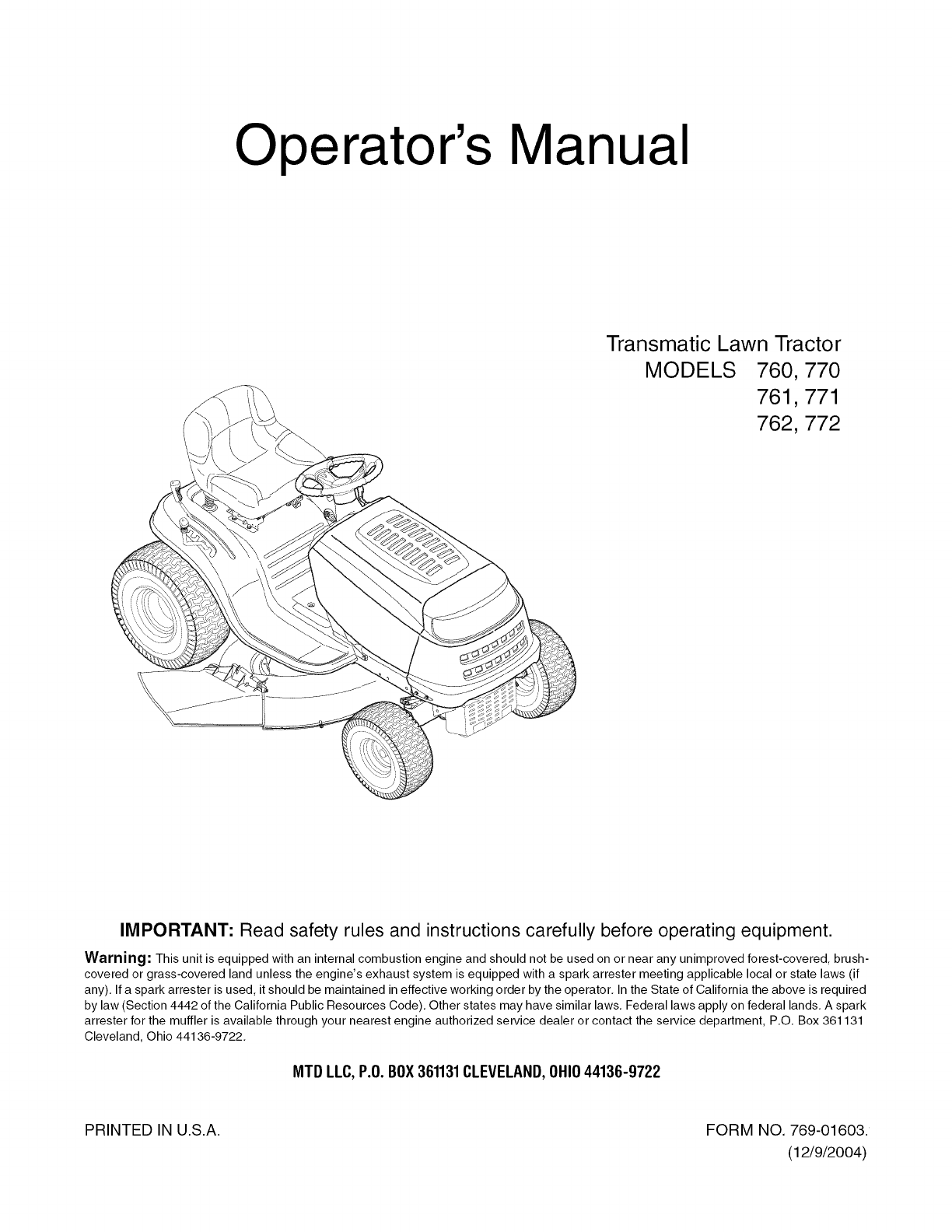
Operator's Manual
Transmatic Lawn Tractor
MODELS 760,770
761,771
762,772
IMPORTANT: Read safety rules and instructions carefully before operating equipment.
Warning: This unit is equipped with an internal combustion engine and should not be used on or near any unimproved forest-covered, brush-
covered or grass-covered land unless the engine's exhaust system is equipped with a spark arrester meeting applicable local or state laws (if
any). If a spark arrester is used, it should be maintained in effective working order by the operator. In the State of California the above is required
by law (Section 4442 of the California Public Resources Code). Other states may have similar laws. Federal laws apply on federal lands. A spark
arrester for the muffler is available through your nearest engine authorized service dealer or contact the service department, P.O. Box 361131
Cleveland, Ohio 44136-9722.
MTB LLC,P.O.BOX361131CLEVELAND,OHIO44136-9722
PRINTED IN U.S.A. FORM NO. 769-01603.
(12/9/2004)
TABLEOFCONTENTS
Content
Customer Support
Important Safe Operation Practices
Tractor Set-up
Controls
Operation
Page Content Page
2 Maintenance 20
3 Service 22
8 Off-season Storage 26
11 Attachments & Accessories 26
14 Warranty Back Cover
FINDINGMODELNUMBER
This Operator's Manual is an important part of your new lawn tractor. It will help you assemble, prepare and
maintain the unit for best performance. Please read and understand what it says.
Before you start assembling your new equipment, please locate the model plate on the equipment
and copy the information from it in the space provided below. A sample model plate is also given below.
You can locate the model plate by looking at the underside of the seat. This information will be necessary
to use the manufacturer's web site and/or help from the Customer Support Department or an authorized
service dealer.
P. O. BOX 361131
CLEVELAND,OH 44136
330-220-4883
www, mtdproducts.corn 800-800-7310
Copy the model number here:
Copy the serial number here:
CUSTOMERSUPPORT
Please doNOTreturn the unRto theretailer wRhoutfirstcontactingCustomerSupport.
If you have difficulty assembling this product or have any questions regarding the controls, operation or
maintenance of this unit, you can seek help from the experts. Choose from the options below:
_En ine
Ma ual
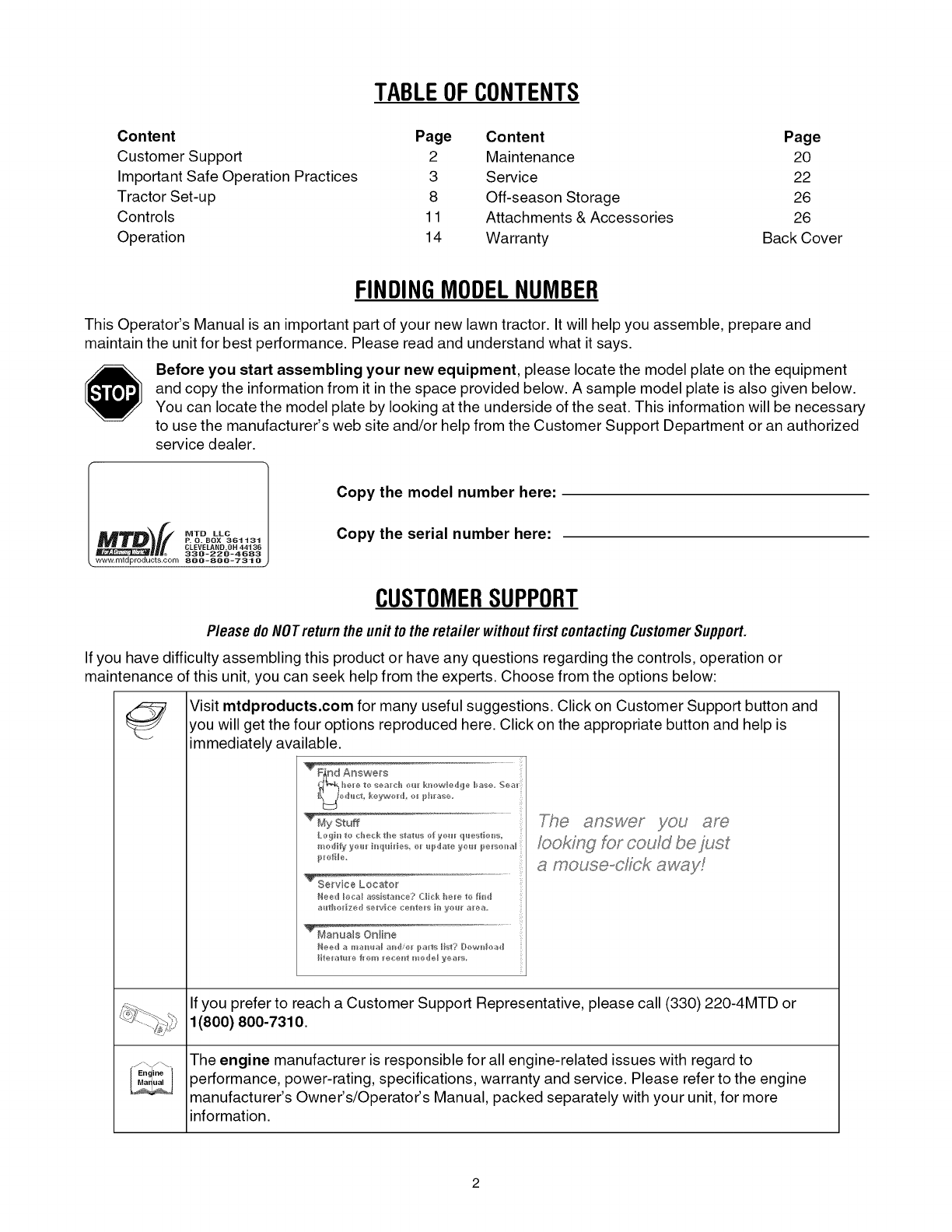
Visit mtdproducts.com for many useful suggestions. Click on Customer Support button and
you will get the four options reproduced here. Click on the appropriate button and help is
immediately available.
TrendAo_we_
fooking for could be just
a mouse-dick aw_,_y!
If you prefer to reach a Customer Support Representative, please call (330) 220-4MTD or
1(800) 800-7310.
The engine manufacturer is responsible for all engine-related issues with regard to
performance, power-rating, specifications, warranty and service. Please refer to the engine
manufacturer's Owner's/Operator's Manual, packed separately with your unit, for more
information.
SECTION1: IMPORTANTSAFEOPERATIONPRACTICES
WARNING: This symbol points out important safety instructions which, if not followed, could endanger
the personal safety and/or property of yourself and others. Read and follow all instructions in this manual
before attempting to operate this machine. Failure to comply with these instructions may result in personal
injury. When you see this symbol--heed its warning.
DANGER: This machine was built to be operated according to the rules for safe operation in this man-
ual. As with any type of power equipment, carelessness or error on the part of the operator can result in
serious injury. This machine is capable of amputating hands and feet and throwing objects. Failure to
observe the following safety instructions could result in serious injury or death.
California Proposition 65 Warning:
,_ WARNING: Engine exhaust, some of its constituents, and certain vehicle components contain
or emit chemicals known to the State of California to cause cancer and birth defects or other
reproductive harm.
GENERAL OPERATION
1. Read, understand, and follow all instructions on the
machine and in the manual(s) before attempting to
assemble and operate. Keep this manual in a safe
place for future and regular reference and for
ordering replacement parts.
2. Be familiar with all controls and their proper
operation. Know how to stop the machine and
disengage them quickly.
3. Never allow children under 14 years old to operate
this machine. Children 14 years old and over
should read and understand the operation
instructions and safety rules in this manual and
should be trained and supervised by a parent.
4. Never allow adults to operate this machine without
proper instruction.
5. To help avoid blade contact or a thrown object
injury, keep bystanders, helpers, children and pets
at least 75 feet from the machine while it is in
operation. Stop machine if anyone enters the area.
6. Thoroughly inspect the area where the equipment
is to be used. Remove all stones, sticks, wire,
bones, toys, and other foreign objects which could
be picked up and thrown by the blade(s). Thrown
objects can cause serious personal injury.
7. Plan your mowing pattern to avoid discharge of
material toward roads, sidewalks, bystanders and
the like. Also, avoid discharging material against a
wall or obstruction which may cause discharged
material to ricochet back toward the operator.
8. Always wear safety glasses or safety goggles
during operation and while performing an
adjustment or repair to protect your eyes. Thrown
objects which ricochet can cause serious injury to
the eyes.
9. Wear sturdy, rough-soled work shoes and close-
fitting slacks and shirts. Loose fitting clothes and
jewelry can be caught in movable parts. Never
operate this machine in bare feet or sandals.
10. Be aware of the mower and attachment discharge
direction and do not point it at anyone. Do not
operate the mower without the discharge cover or
entire grass catcher in its proper place.
11. Do not put hands or feet near rotating parts or
under the cutting deck. Contact with the blade(s)
can amputate hands and feet.
12. A missing or damaged discharge cover can cause
blade contact or thrown object injuries.
13. Stop the blade(s) when crossing gravel drives,
walks, or roads and while not cutting grass.
14. Watch for traffic when operating near or crossing
roadways. This machine is not intended for use on
any public roadway.
15. Do not operate the machine while under the
influence of alcohol or drugs.
16. Mow only in daylight or good artificial light.
17. Never carry passengers.
18. Disengage blade(s) before shifting into reverse.
Back up slowly. Always look down and behind
before and while backing to avoid a back-over
accident.
19. Slow down before turning. Operate the machine
smoothly. Avoid erratic operation and excessive
speed.
20. Disengage blade(s), set parking brake, stop engine
and wait until the blade(s) come to a complete stop
before removing grass catcher, emptying grass,
unclogging chute, removing any grass or debris, or
making any adjustments.
21. Never leave a running machine unattended.
Always turn off blade(s), place transmission in
neutral, set parking brake, stop engine and remove
key before dismounting.
22. Use extra care when loading or unloading the
machine into a trailer or truck. This unit should not
be driven up or down ramp(s), because the unit
could tip over, causing serious personal injury. The
unit must be pushed manually on ramp(s) to load or
unload properly.
23.Mufflerandenginebecomehotandcancausea
burn.Donottouch.
24.Checkoverheadclearancescarefullybeforedriving
underlowhangingtreebranches,wires,door
openingsetc.,wheretheoperatormaybestruckor
pulledfromtheunit,whichcouldresultinserious
injury.
25.Disengageallattachmentclutches,depressthe
brakepedalcompletelyandshiftintoneutralbefore
attemptingto startengine.
26.Yourmachineisdesignedtocutnormalresidential
grassofaheightnomorethan10".Donotattempt
to mowthroughunusuallytall,drygrass(e.g.,
pasture)orpilesofdryleaves.Drygrassorleaves
maycontacttheengineexhaustand/orbuildupon
themowerdeckpresentingapotentialfirehazard.
27.Useonlyaccessoriesandattachmentsapproved
forthismachinebythemachinemanufacturer.
Read,understandandfollowallinstructions
providedwiththeapprovedaccessoryor
attachment.
28.Dataindicatesthatoperators,age60yearsand
above,areinvolvedinalargepercentageofriding
mower-relatedinjuries.Theseoperatorsshould
evaluatetheirabilitytooperatetheridingmower
safelyenoughtoprotectthemselvesandothers
fromseriousinjury.
29.Ifsituationsoccurwhicharenotcoveredinthis
manual,usecareandgoodjudgment.Contactan
authorizedMTDServiceDealerforassistance.
SLOPE OPERATION
Slopes are a major factor related to loss of control and
tip-over accidents which can result in severe injury or
death. All slopes require extra caution. If you cannot
back up the slope or if you feel uneasy on it, do not mow
it.
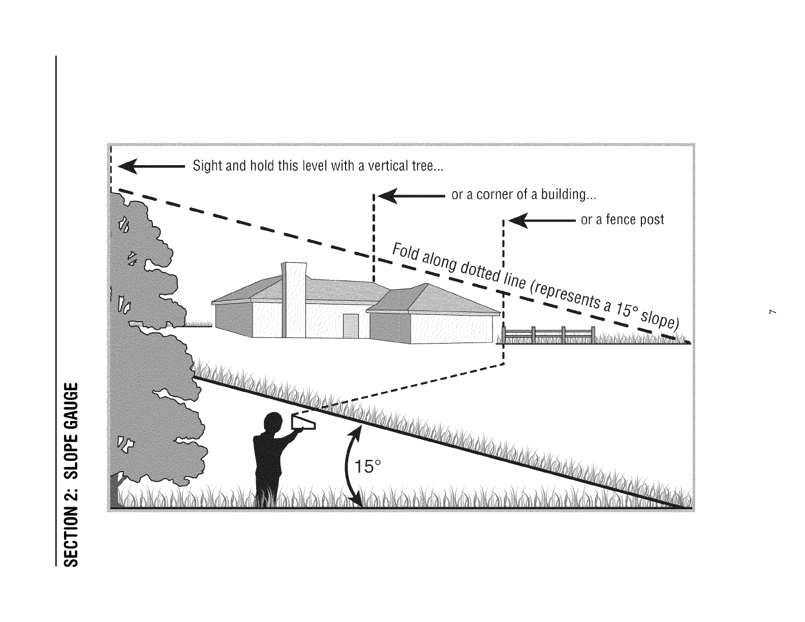
For your safety, use the slope gauge included as part of
this manual to measure slopes before operating this
unit on a sloped or hilly area. If the slope is greater than
15 degrees as shown on the slope gauge, do not
operate this unit on that area or serious injury could
result.
DO:
1. Mow up and down slopes, not across. Exercise
extreme caution when changing direction on
slopes.
2. Watch for holes, ruts, bumps, rocks, or other
hidden objects. Uneven terrain could overturn the
machine. Tall grass can hide obstacles.
3. Use slow speed. Choose a low enough speed
setting so that you will not have to stop or shift while
on the slope. Tires may lose traction on slopes
even though the brakes are functioning properly.
Always keep machine in gear when going down
slopes to take advantage of engine braking action.
4. Follow the manufacturer's recommendations for
wheel weights or counterweights to improve
stability.
5. Use extra care with grass catchers or other
attachments. These can change the stability of the
machine.
6. Keep all movement on the slopes slow and gradual.
Do not make sudden changes in speed or direction.
Rapid engagement or braking could cause the front
of the machine to lift and rapidly flip over backwards
which could cause serious injury.
7. Avoid starting or stopping on a slope. If tires lose
traction, disengage the blade(s) and proceed
slowly straight down the slope.
DO NOT:
1. Do not turn on slopes unless necessary; then, turn
slowly and gradually downhill, if possible.
2. Do not mow near drop-offs, ditches or
embankments. The mower could suddenly turn
over if a wheel is over the edge of a cliff, ditch, or if
an edge caves in.
3. Do not try to stabilize the machine by putting your
foot on the ground.
4. Do not use a grass catcher on steep slopes.
5. Do not mow on wet grass. Reduced traction could
cause sliding.
6. Do not shift to neutral and coast downhill. Over-
speeding may cause the operator to lose control of
the machine resulting in serious injury or death.
7. Do not tow heavy pull behind attachments (e.g.
loaded dump cart, lawn roller, etc.) on slopes
greater than 5 degrees. When going down hill, the
extra weight tends to push the tractor and may
cause you to loose control. (e.g. tractor may speed
up, braking and steering ability are reduced,
attachment may jack-knife and cause tractor to
overturn).
CHILDREN
,Tragic accidents can occur if the operator is not
alert to the presence of children. Children are often
attracted to the machine and the mowing activity.
They do not understand the dangers. Never
assume that children will remain where you last
saw them.
a. Keep children out of the mowing area and in
watchful care of a responsible adult other
than the operator.
b. Be alert and turn machine off if a child enters
the area.
c. Before and while backing, look behind and
down for small children.
d. Never carry children, even with the blade(s)
shut off. They may fall off and be seriously
injured or interfere with safe machine
operation.
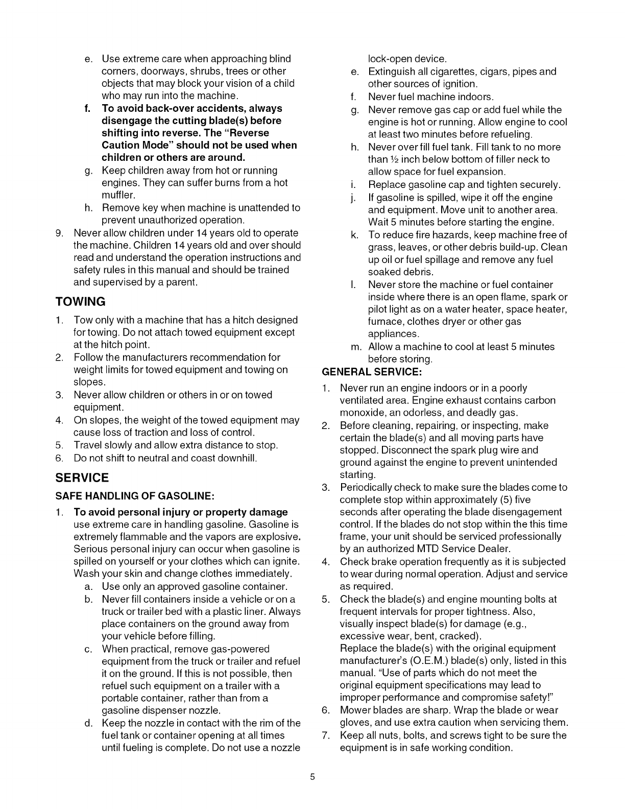
e. Useextremecarewhenapproachingblind
corners,doorways,shrubs,treesorother
objectsthatmayblockyourvisionofachild
whomayrunintothemachine.
f. Toavoidback-overaccidents,always
disengagethecuttingblade(s)before
shiftingintoreverse.The"Reverse
CautionMode" should not be used when
children or others are around.
g. Keep children away from hot or running
engines. They can suffer burns from a hot
muffler.
h. Remove key when machine is unattended to
prevent unauthorized operation.
Never allow children under 14 years old to operate
the machine. Children 14 years old and over should
read and understand the operation instructions and
safety rules in this manual and should be trained
and supervised by a parent.
,
TOWING
1. Tow only with a machine that has a hitch designed
for towing. Do not attach towed equipment except
at the hitch point.
2. Follow the manufacturers recommendation for
weight limits for towed equipment and towing on
slopes.
3. Never allow children or others in or on towed
equipment.
4. On slopes, the weight of the towed equipment may
cause loss of traction and loss of control.
5. Travel slowly and allow extra distance to stop.
6. Do not shift to neutral and coast downhill.
SERVICE
SAFE HANDLING OF GASOLINE:
To avoid personal injury or property damage
use extreme care in handling gasoline. Gasoline is
extremely flammable and the vapors are explosive.
Serious personal injury can occur when gasoline is
spilled on yourself or your clothes which can ignite.
Wash your skin and change clothes immediately.
a. Use only an approved gasoline container.
b. Never fill containers inside a vehicle or on a
truck or trailer bed with a plastic liner. Always
place containers on the ground away from
your vehicle before filling.
c. When practical, remove gas-powered
equipment from the truck or trailer and refuel
it on the ground. If this is not possible, then
refuel such equipment on a trailer with a
portable container, rather than from a
gasoline dispenser nozzle.
d. Keep the nozzle in contact with the rim of the
fuel tank or container opening at all times
until fueling is complete. Do not use a nozzle
,
lock-open device.
e. Extinguish all cigarettes, cigars, pipes and
other sources of ignition.
f. Neverfuel machine indoors.
g. Never remove gas cap or add fuel while the
engine is hot or running. Allow engine to cool
at least two minutes before refueling.
h. Never over fill fuel tank. Fill tankto no more
than _/2inch below bottom of filler neck to
allow space for fuel expansion.
i. Replace gasoline cap and tighten securely.
j. If gasoline is spilled, wipe it off the engine
and equipment. Move unit to another area.
Wait 5 minutes before starting the engine.
k. To reduce fire hazards, keep machine free of
grass, leaves, or other debris build-up. Clean
up oil or fuel spillage and remove any fuel
soaked debris.
I. Never store the machine or fuel container
inside where there is an open flame, spark or
pilot light as on a water heater, space heater,
furnace, clothes dryer or other gas
appliances.
m. Allow a machine to cool at least 5 minutes
before storing.
GENERAL SERVICE:
1. Never run an engine indoors or in a poorly
ventilated area. Engine exhaust contains carbon
monoxide, an odorless, and deadly gas.
2. Before cleaning, repairing, or inspecting, make
certain the blade(s) and all moving parts have
stopped. Disconnect the spark plug wire and
ground against the engine to prevent unintended
starting.
3. Periodically check to make sure the blades come to
complete stop within approximately (5) five
seconds after operating the blade disengagement
control. If the blades do not stop within the this time
frame, your unit should be serviced professionally
by an authorized MTD Service Dealer.
4. Check brake operation frequently as it is subjected
to wear during normal operation. Adjust and service
as required.
5. Check the blade(s) and engine mounting bolts at
frequent intervals for proper tightness. Also,
visually inspect blade(s) for damage (e.g.,
excessive wear, bent, cracked).
Replace the blade(s) with the original equipment
manufacturer's (O.E.M.) blade(s) only, listed in this
manual. "Use of parts which do not meet the
original equipment specifications may lead to
improper performance and compromise safety!"
6. Mower blades are sharp. Wrap the blade or wear
gloves, and use extra caution when servicing them.
7. Keep all nuts, bolts, and screws tight to be sure the
equipment is in safe working condition.
8. Nevertamperwiththesafetyinterlocksystemor
othersafetydevices.Checktheirproperoperation
regularly.
9. Afterstrikingaforeignobject,stoptheengine,
disconnectthesparkplugwire(s)andground
againsttheengine.Thoroughlyinspectthe
machineforanydamage.Repairthedamage
beforestartingandoperating.
10.Neverattemptto makeadjustmentsorrepairsto
themachinewhiletheengineisrunning.
11.Grasscatchercomponentsandthedischarge
coveraresubjecttowearanddamagewhichcould
exposemovingpartsorallowobjectsto bethrown.
12.
13.
14.
Forsafetyprotection,frequentlycheckcomponents
andreplaceimmediatelywithoriginalequipment
manufacturer's(O.E.M.)partsonly,listedinthis
manual."Useofpartswhichdonotmeetthe
originalequipmentspecificationsmayleadto
improperperformanceandcompromisesafety!"
Donotchangetheenginegovernorsettingsor
over-speedtheengine.Thegovernorcontrolsthe
maximumsafeoperatingspeedoftheengine.
Maintainorreplacesafetyandinstructionlabels,as
necessary.
Observeproperdisposallawsandregulationsfor
gas,oil,etc.toprotecttheenvironment.
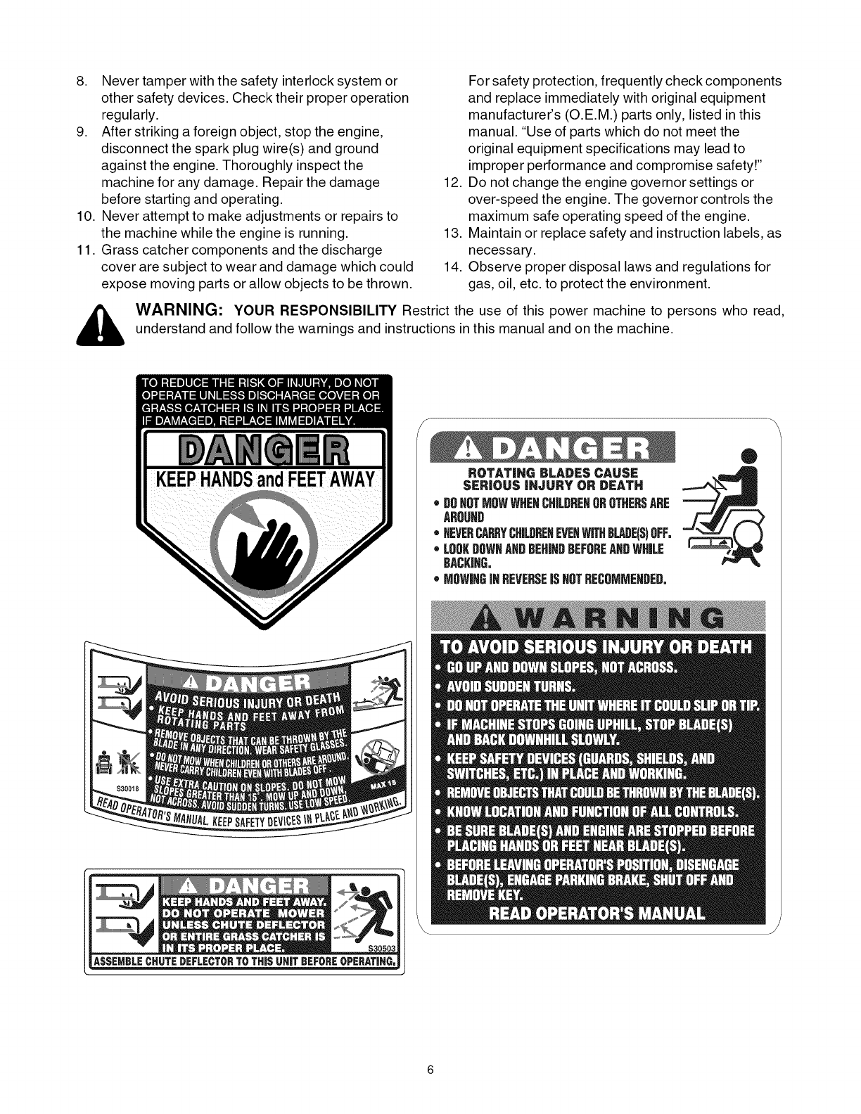
_, ARNING: YOURRESPONSIBILITYRestricttheuseof thispowermachineto personswhoread,
understandandfollowthewarningsandinstructionsinthismanualandonthemachine.
ROTATING BLADES CAUSE
SERIOUS iNJURY OR DEATH
•DOHOTMOWWHENCHILBREHOROTHERSARE
AROUHD
• HEVERCAP_YCH&DREHEVEHWITHBLADE(S)OFF.
•LOOKDOWNAHDBEHINDBEFOREANDWHILE
BACKING.
oMOWINGiNREVERSEJSHOTRECOMMEHDED.
®
I.LI
I.LI
a.
64
Z
I.LI
_ Sight and hold this level with a vertical tree...
15°
SECTION3: TRACTORSET-UP
IMPORTANT:Your tractor is shipped with motor oil in the engine. However, you MUST check the oil level before
starting the engine and operating the tractor. Refer to the separate engine manufacturer's Operator/Owner Manual
packed w th your tractor. Read nstruct ons carefu y.
LooseParts Figure 1
Packaged with this Operator's Manual you'll find:
• One Small Clamp (726-0354)
• One 1/4-20 x 1/2-inch Screw (710-0599)
• One Oil Drain Sleeve (731-1682A)
Store the clamp and screw in a convenient place. Both
will be necessary to properly secure your tractor's wire
harness should you choose to purchase a front-end
attachment for your lawn tractor. Refer to page 26 for a
table of available attachments and accessories.
Refer to page20 for information regarding the oil drain
sleeve and changing your engine oil.
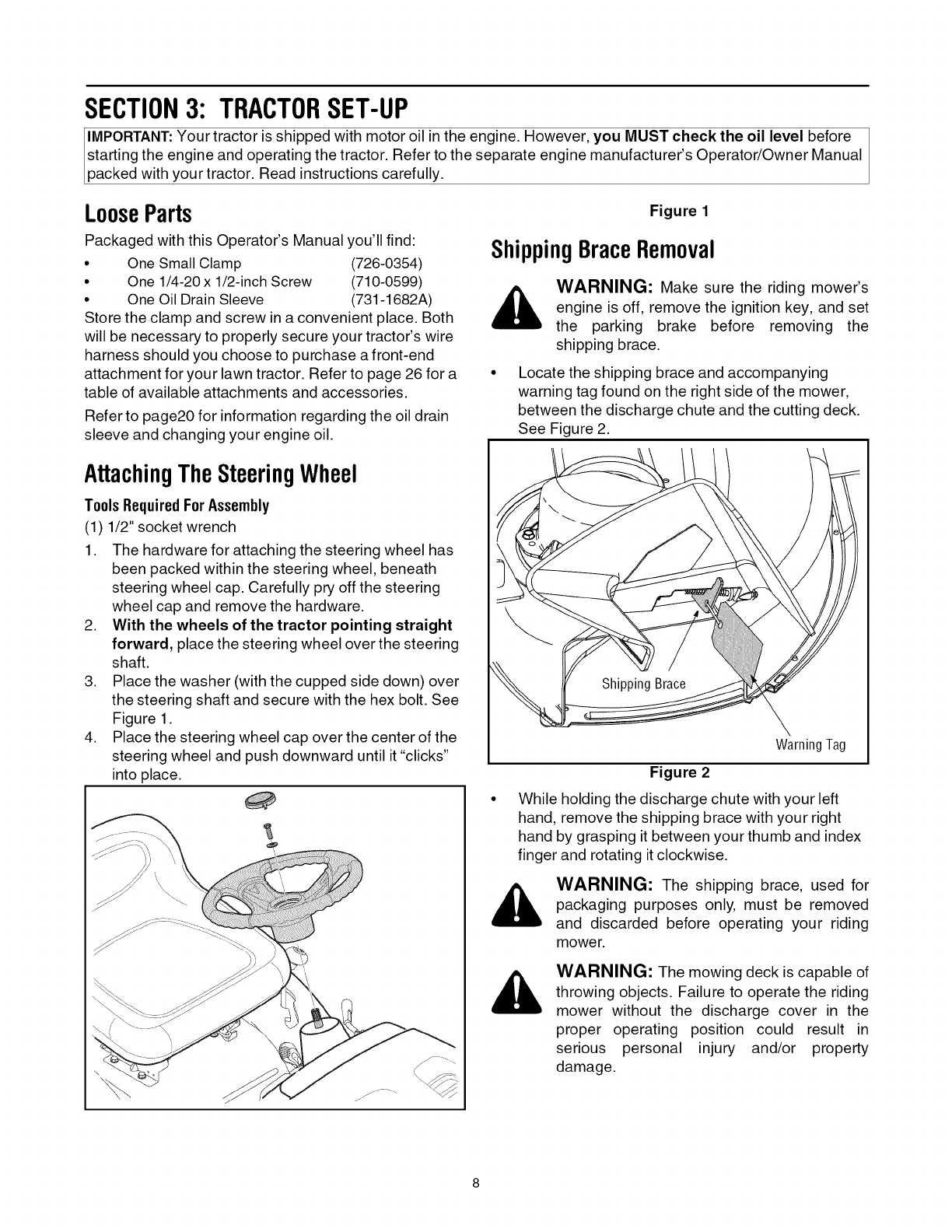
ShippingBraceRemoval
_, WARNING: Make sure the riding mower's
engine is off, remove the ignition key, and set
the parking brake before removing the
shipping brace.
Locate the shipping brace and accompanying
warning tag found on the right side of the mower,
between the discharge chute and the cutting deck.
See Figure 2.
AttachingTheSteeringWheel
ToolsRequiredForAssembly
(1) 1/2" socket wrench
1. The hardware for attaching the steering wheel has
been packed within the steering wheel, beneath
steering wheel cap. Carefully pry off the steering
wheel cap and remove the hardware.
2. With the wheels of the tractor pointing straight
forward, place the steering wheel over the steering
shaft.
3. Place the washer (with the cupped side down) over
the steering shaft and secure with the hex bolt. See
Figure 1.
4. Place the steering wheel cap over the center of the
steering wheel and push downward until it "clicks"
into place.
Warning Tag
Figure 2
While holding the discharge chute with your left
hand, remove the shipping brace with your right
hand by grasping it between your thumb and index
finger and rotating it clockwise.
WARNING: The shipping brace, used for
packaging purposes only, must be removed
and discarded before operating your riding
mower.
WARNING: The mowing deck is capable of
throwing objects. Failure to operate the riding
mower without the discharge cover in the
proper operating position could result in
serious personal injury and/or property
damage.
AttachingtheBatteryCables
NOTE: Some models are shipped with the battery
cables already connected.
NOTE: The positive battery terminal is marked Pos.
(+). The negative battery terminal is marked Neg. (-).
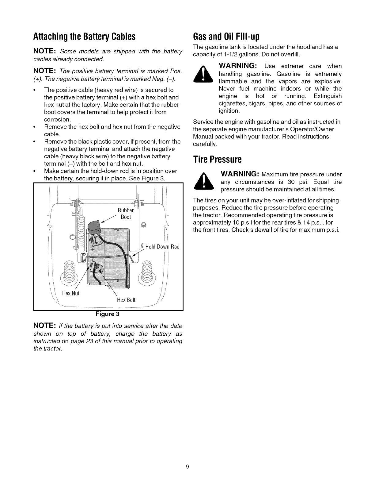
• The positive cable (heavy red wire) is secured to
the positive battery terminal (+) with a hex bolt and
hex nut at the factory. Make certain that the rubber
boot covers the terminal to help protect it from
corrosion.
• Remove the hex bolt and hex nut from the negative
cable.
• Remove the black plastic cover, if present, from the
negative battery terminal and attach the negative
cable (heavy black wire) to the negative battery
terminal (-) with the bolt and hex nut.
• Make certain the hold-down rod is in position over
the battery, securing it in place. See Figure 3.
HoldDownRod
HexNut HexBolt
Figure 3
NOTE: If the battery is put into service after the date
shown on top of battery, charge the battery as
instructed on page 23 of this manual prior to operating
the tractor.
GasandOilFill-up
The gasoline tank is located under the hood and has a
capacity of 1-1/2 gallons. Do not overfill.
WARNING: Use extreme care when
handling gasoline. Gasoline is extremely
flammable and the vapors are explosive.
Never fuel machine indoors or while the
engine is hot or running. Extinguish
cigarettes, cigars, pipes, and other sources of
ignition.
Service the engine with gasoline and oil as instructed in
the separate engine manufacturer's Operator/Owner
Manual packed with your tractor. Read instructions
carefully.
Tire Pressure
_. WARNING: Maximum tire pressure under
any circumstances is 30 psi. Equal tire
pressure should be maintained at all times.
The tires on your unit may be over-inflated for shipping
purposes. Reduce the tire pressure before operating
the tractor. Recommended operating tire pressure is
approximately 10 p.s.i for the rear tires & 14 p.s.i, for
the front tires. Check sidewall of tire for maximum p.s.i.
AttachingTheSeat
Seat styles vary by tractor model and there are three
different styles available:
•Standard Adjustment
• Quick Adjustment &
• Knob Adjustment
Refer to Figure 4, Figure 5 and Figure 6 to identify your
tractor's seat style and follow applicable instructions
below.
NOTE: For shipping reasons, seats are either
fastened to the tractor seat's pivot bracket with a plastic
tie, or mounted backward to the pivot bracket. In either
case, free the seat from its shipping position and
remove the two hex screws (or knobs, on models so
equipped) from the bottom of seat before proceeding
with applicable instructions below.
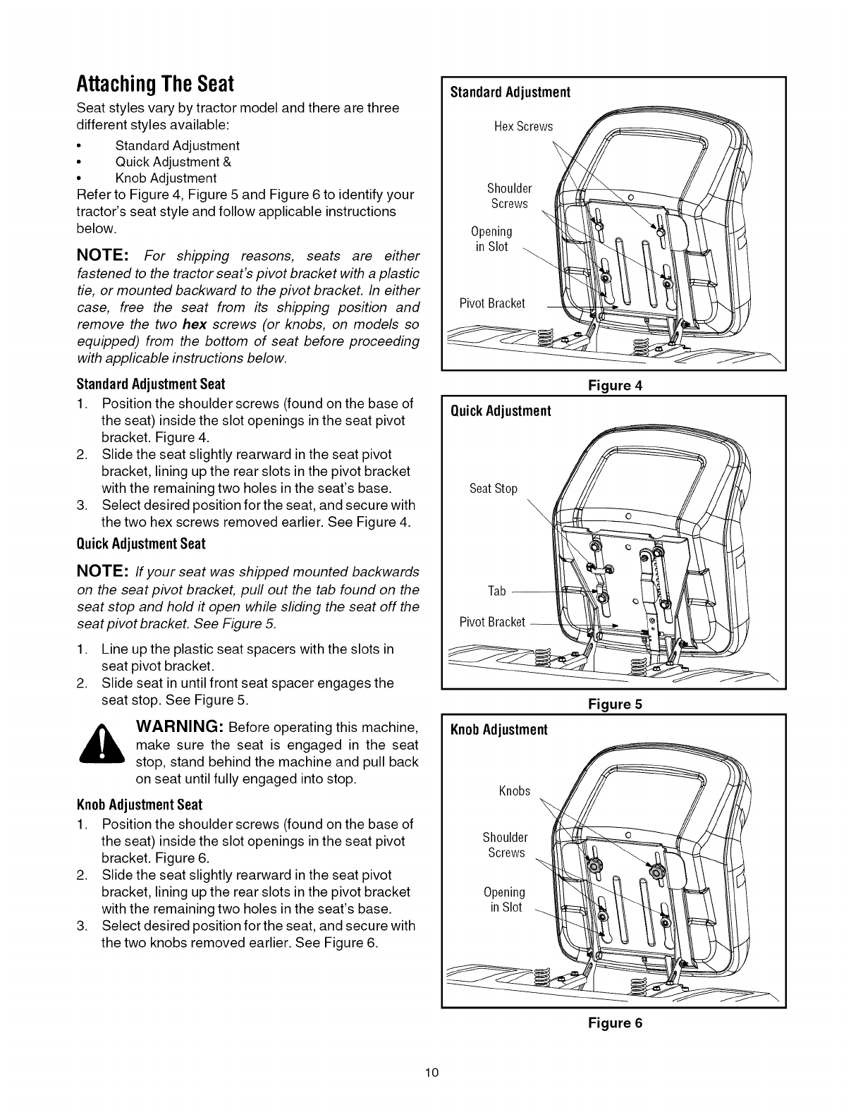
Standard AdjustmentSeat
1. Position the shoulder screws (found on the base of
the seat) inside the slot openings in the seat pivot
bracket. Figure 4.
2. Slide the seat slightly rearward in the seat pivot
bracket, lining up the rear slots in the pivot bracket
with the remaining two holes in the seat's base.
3. Select desired position for the seat, and secure with
the two hex screws removed earlier. See Figure 4.
QuickAdjustmentSeat
NOTE: If your seat was shipped mounted backwards
on the seat pivot bracket, pull out the tab found on the
seat stop and hold #open while sliding the seat off the
seat pivot bracket. See Figure 5.
1. Line up the plastic seat spacers with the slots in
seat pivot bracket.
2. Slide seat in until front seat spacer engages the
seat stop. See Figure 5.
WARNING: Before operating this machine,
make sure the seat is engaged in the seat
stop, stand behind the machine and pull back
on seat until fully engaged into stop.
KnobAdjustmentSeat
1. Position the shoulder screws (found on the base of
the seat) inside the slot openings in the seat pivot
bracket. Figure 6.
2. Slide the seat slightly rearward in the seat pivot
bracket, lining up the rear slots in the pivot bracket
with the remaining two holes in the seat's base.
3. Select desired position for the seat, and secure with
the two knobs removed earlier. See Figure 6.
Standard Adjustment
HexScrews
Shoulder
Screws
Opening
in SI0t
Pivot Bracket
QuickAdjustment
Figure 4
SeatStop
Tab --
Pivot Bracket --
\
KnobAdjustment
Figure 5
Knobs
Shoulder
Screws
Opening
inSlot
Figure 6
lO
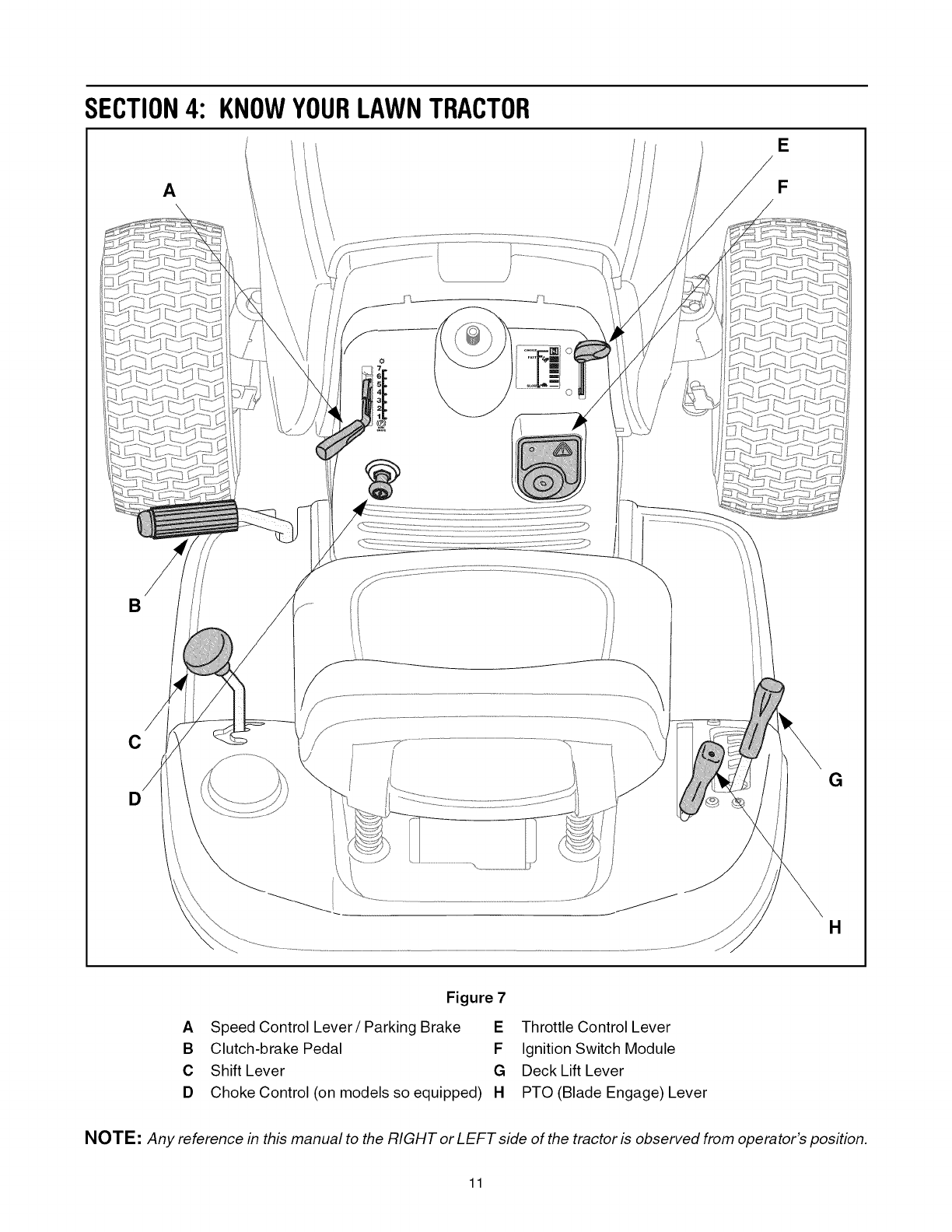
SECTION4: KNOWYOURLAWNTRACTOR
A
l/
/ii
/
E
F
B
C
D
\\
G
H
Figure 7
ASpeed Control Lever/Parking Brake E
B Clutch-brake Pedal F
C Shift Lever G
D Choke Control (on models so equipped) H
Throttle Control Lever
Ignition Switch Module
Deck Lift Lever
PTO (Blade Engage) Lever
NOTE: Any reference in this manual to the RIGHT or LEFT side of the tractor is observed from operator's position.
11
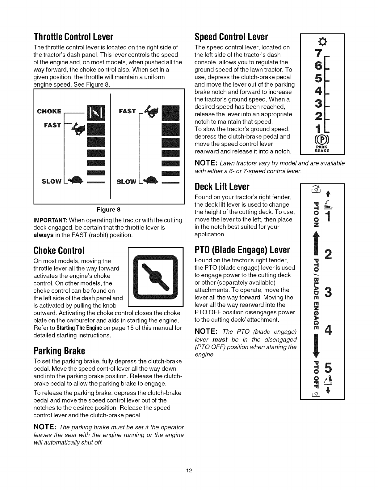
ThrottleControlLever
The throttle control lever is located on the right side of
the tractor's dash panel. This lever controls the speed
of the engine and, on most models, when pushed all the
way forward, the choke control also. When set in a
given position, the throttle will maintain a uniform
engine speed. See Figure 8.
CHOKE
FAST
SLOW
- EE EE
SLOW _'_
Figure 8
IMPORTANT:When operating the tractor with the cutting
deck engaged, be certain that the throttle lever is
always in the FAST (rabbit) position.
ChokeControl
On most models, moving the
throttle lever all the way forward
activates the engine's choke
control. On other models, the
choke control can be found on
the left side of the dash panel and
is activated by pulling the knob
outward. Activating the choke control closes the choke
plate on the carburetor and aids in starting the engine.
Refer to StartingTheEngineon page 15 of this manual for
detailed starting instructions.
ParkingBrake
To set the parking brake, fully depress the clutch-brake
pedal. Move the speed control lever all the way down
and into the parking brake position. Release the clutch-
brake pedal to allow the parking brake to engage.
To release the parking brake, depress the clutch-brake
pedal and move the speed control lever out of the
notches to the desired position. Release the speed
control lever and the clutch-brake pedal.
NOTE: The parking brake must be set if the operator
leaves the seat with the engine running or the engine
will automatically shut off.
SpeedControlLever
The speed control lever, located on
the left side of the tractor's dash
console, allows you to regulate the
ground speed of the lawn tractor. To
use, depress the clutch-brake pedal
and move the lever out of the parking
brake notch and forward to increase
the tractor's ground speed. When a
desired speed has been reached,
release the lever into an appropriate
notch to maintain that speed.
To slow the tractor's ground speed,
depress the clutch-brake pedal and
move the speed control lever
rearward and release it into a notch.
0
PARK
BRAKE
NOTE: Lawn tractors vary by model and are available
with either a 6- or 7-speed control lever.
DeckLiftLever
Found on your tractor's right fender,
the deck lift lever is used to change
the height of the cutting deck. To use,
move the lever to the left, then place
inthe notch best suited for your
application.
PTO(BladeEngage)Lever
Found on the tractor's right fender,
the PTO (blade engage) lever is used
to engage power to the cutting deck
or other (separately available)
attachments. To operate, move the
lever all the way forward. Moving the
lever all the way rearward into the
PTO OFF position disengages power
to the cutting deck/attachment.
NOTE: The PTO (blade engage)
lever must be in the disengaged
(PTO OFF) position when starting the
engine.
_lwf .:
0
ol
z
f
,,g
O
w
m
Z
m
!
O
L_O
2
3
4
5
12
Clutch-BrakePedal
The clutch-brake pedal is located on the left side of the
lawn tractor, along the running board. Depress the
clutch-brake pedal part way down when slowing the
tractor by changing speeds (Refer to SpeedControlLever).
Depress the pedal all the way down to engage the disc
brake and bring the tractor to a complete stop.
NOTE: The pedal must be depressed to start the
engine. Refer to SafetyInterlockSwitcheson page 14.
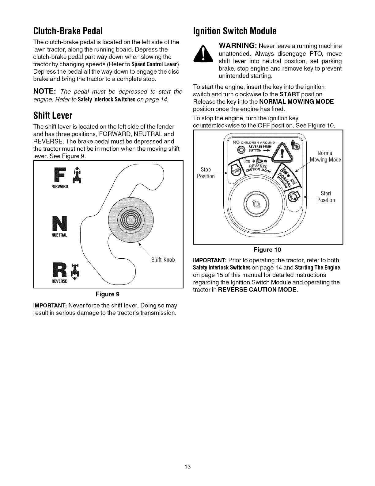
ShiftLever
The shift lever is located on the left side of the fender
and has three positions, FORWARD, NEUTRAL and
REVERSE. The brake pedal must be depressed and
the tractor must not be in motion when the moving shift
lever. See Figure 9.
4_
:8RWARD
MUETRAL
REVERSE
Shift Knob
Figure 9
IMPORTANT: Never force the shift lever. Doing so may
result in serious damage to the tractor's transmission.
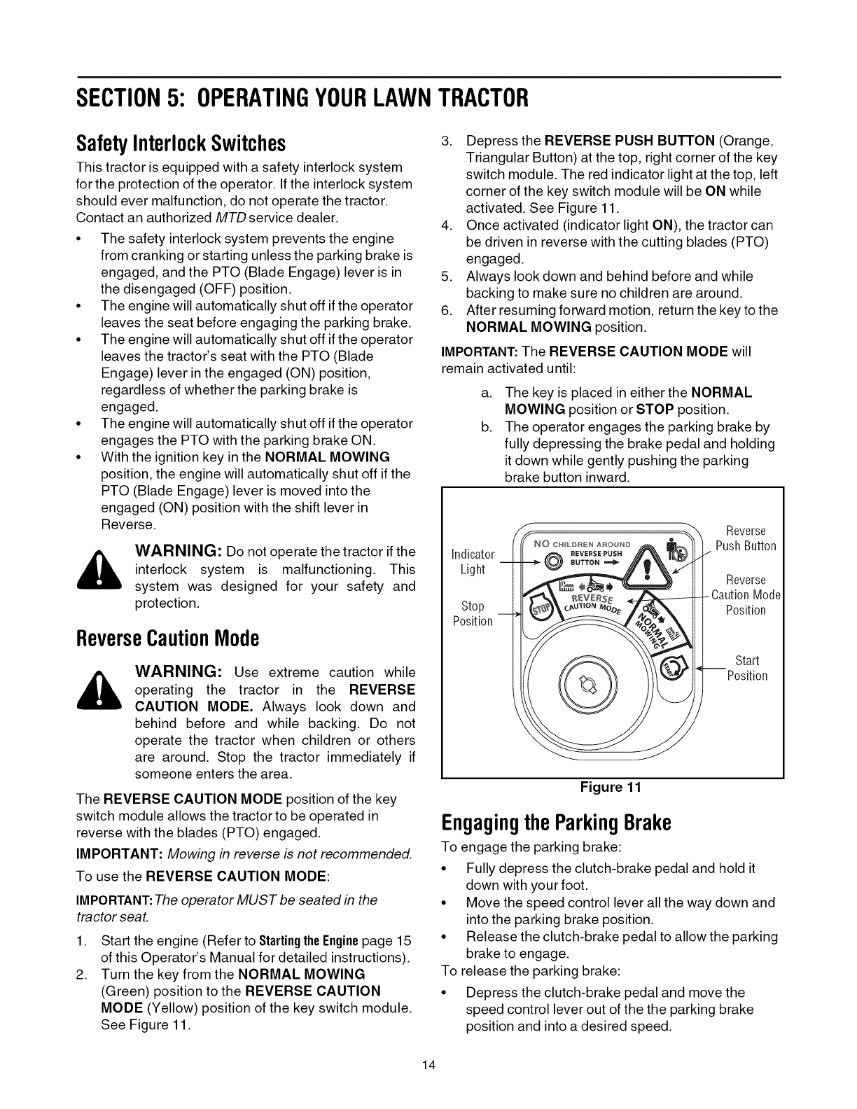
IgnitionSwitch Module
WARNING: Never leave a running machine
unattended. Always disengage PTO, move
shift lever into neutral position, set parking
brake, stop engine and remove key to prevent
unintended starting.
To start the engine, insert the key into the ignition
switch and turn clockwise to the START position.
Release the key into the NORMAL MOWING MODE
position once the engine has fired.
To stop the engine, turn the ignition key
counterclockwise to the OFF position. See Figure 10.
Stop
Position
NO CHILDREN AROUND
REVERSEPUSH
BUTTON"_ Normal
MowingMode
Start
Position
Figure 10
IMPORTANT: Prior to operating the tractor, refer to both
SafetyInterlockSwitcheson page 14 and StartingThe Engine
on page 15 of this manual for detailed instructions
regarding the Ignition Switch Module and operating the
tractor in REVERSE CAUTION MODE.
13
SECTION5: OPERATINGYOURLAWNTRACTOR
SafetyInterlockSwitches
This tractor is equipped with a safety interlock system
for the protection of the operator. If the interlock system
should ever malfunction, do not operate the tractor.
Contact an authorized MTD service dealer.
• The safety interlock system prevents the engine
from cranking or starting unless the parking brake is
engaged, and the PTO (Blade Engage) lever is in
the disengaged (OFF) position.
• The engine will automatically shut off if the operator
leaves the seat before engaging the parking brake.
• The engine will automatically shut off if the operator
leaves the tractor's seat with the PTO (Blade
Engage) lever in the engaged (ON) position,
regardless of whether the parking brake is
engaged.
• The engine will automatically shut off if the operator
engages the PTO with the parking brake ON.
• With the ignition key in the NORMAL MOWING
position, the engine will automatically shut off if the
PTO (Blade Engage) lever is moved into the
engaged (ON) position with the shift lever in
Reverse.
WARNING: Do not operate the tractor if the
interlock system is malfunctioning. This
system was designed for your safety and
protection.
ReverseCautionMode
WARNING: Use extreme caution while
operating the tractor in the REVERSE
CAUTION MODE. Always look down and
behind before and while backing. Do not
operate the tractor when children or others
are around. Stop the tractor immediately if
someone enters the area.
The REVERSE CAUTION MODE position of the key
switch module allows the tractor to be operated in
reverse with the blades (PTO) engaged.
IMPORTANT: Mowing in reverse is not recommended.
To use the REVERSE CAUTION MODE:
IMPORTANT:The operator MUST be seated in the
tractor seat.
,
2.
Start the engine (Refer to Startingthe Enginepage 15
of this Operator's Manual for detailed instructions).
Turn the key from the NORMAL MOWING
(Green) position to the REVERSE CAUTION
MODE (Yellow) position of the key switch module.
See Figure 11.
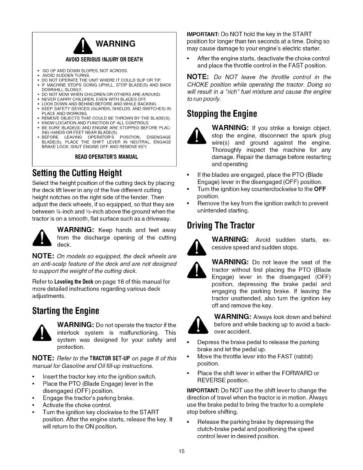
3. Depress the REVERSE PUSH BUTTON (Orange,
Triangular Button) at the top, right corner of the key
switch module. The red indicator light at the top, left
corner of the key switch module will be ON while
activated. See Figure 11.
4. Once activated (indicator light ON), the tractor can
be driven in reverse with the cutting blades (PTO)
engaged.
5. Always look down and behind before and while
backing to make sure no children are around.
6. After resuming forward motion, return the key to the
NORMAL MOWING position.
IMPORTANT: The REVERSE CAUTION MODE will
remain activated until:
a,
b.
The key is placed in either the NORMAL
MOWING position or STOP position.
The operator engages the parking brake by
fully depressing the brake pedal and holding
it down while gently pushing the parking
brake button inward.
indicator
Light
Stop
Position
Reverse
PushButton
Reverse
-CautionMode
Position
Start
Position
Figure 11
Engagingthe ParkingBrake
To engage the parking brake:
• Fully depress the clutch-brake pedal and hold it
down with your foot.
• Move the speed control lever all the way down and
into the parking brake position.
• Release the clutch-brake pedal to allow the parking
brake to engage.
To release the parking brake:
• Depress the clutch-brake pedal and move the
speed control lever out of the the parking brake
position and into a desired speed.
14
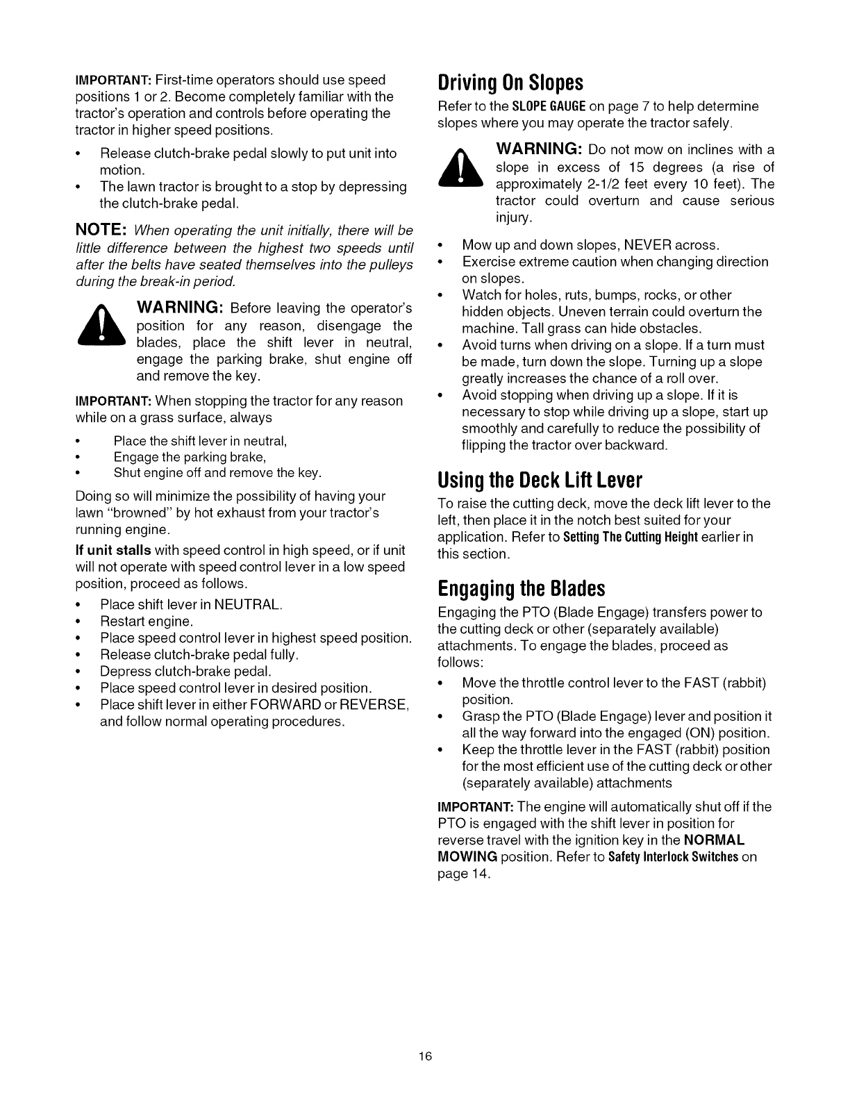
WARNING
AVOIDSERIOUSINJURYORDEATH
• GO UP AND DOWN SLOPES, NOT ACROSS.
• AVOID SUDDEN TURNS.
• DO NOT OPERATE THE UNIT WHERE IT COULD SLIP OR TIR
• IF MACHINE STOPS GOING UPHILL, STOP BLADE(S) AND BACK
DOWNHILL SLOWLY.
• DO NOT MOW WHEN CHILDREN OR OTHERS ARE AROUND.
• NEVER CARRY CHILDREN, EVEN WITH BLADES OFR
• LOOK DOWN AND BEHIND BEFORE AND WHILE BACKING.
• KEEP SAFETY DEVICES (GUARDS, SHIELDS, AND SWITCHES) IN
PLACE AND WORKING.
• REMOVE OBJECTS THAT COULD BE THROWN BY THE BLADE(S).
• KNOW LOCATION AND FUNCTION OF ALL CONTROLS.
• BE SURE BLADE(S) AND ENGINE ARE STOPPED BEFORE PLAC-
ING HANDS OR FEET NEAR BLADE(S).
• BEFORE LEAVING OPERATOR'S POSITION, DISENGAGE
BLADE(S), PLACE THE SHIFT LEVER IN NEUTRAL, ENGAGE
BRAKE LOCK, SHUT ENGINE OFF AND REMOVE KEY.
READOPERATOR'SMANUAL
SettingtheCuttingHeight
Select the height position of the cutting deck by placing
the deck lift lever in any of the five different cutting
height notches on the right side of the fender. Then
adjust the deck wheels, if so equipped, so that they are
between 1A-inch and _/2-inchabove the ground when the
tractor is on a smooth, flat surface such as a driveway.
_, ARNING: Keep hands and feet away
from the discharge opening of the cutting
deck.
NOTE: On models so equipped, the deck wheels are
an anti-scalp feature of the deck and are not designed
to support the weight of the cutting deck.
Refer to LevelingtheDeckon page 18 of this manual for
more detailed instructions regarding various deck
adjustments.
StartingtheEngine
WARNING: Do not operate the tractor if the
interlock system is malfunctioning. This
system was designed for your safety and
protection.
NOTE: Refer to the TRACTORSET-UPon page 8 of this
manual for Gasoline and Oil till-up instructions.
• Insert the tractor key into the ignition switch.
• Place the PTO (Blade Engage) lever in the
disengaged (OFF) position.
• Engage the tractor's parking brake.
• Activate the choke control.
• Turn the ignition key clockwise to the START
position. After the engine starts, release the key. It
will return to the ON position.
IMPORTANT: Do NOT hold the key in the START
position for longer than ten seconds at a time. Doing so
may cause damage to your engine's electric starter.
• After the engine starts, deactivate the choke control
and place the throttle control in the FAST position.
NOTE: Do NOT leave the throttle control in the
CHOKE position while operating the tractor. Doing so
will result in a "rich" fuel mixture and cause the engine
to run poorly.
StoppingtheEngine
_. WARNING: If you strike a foreign object,
stop the engine, disconnect the spark plug
wire(s) and ground against the engine.
Thoroughly inspect the machine for any
damage. Repair the damage before restarting
and operating
• If the blades are engaged, place the PTO (Blade
Engage) lever in the disengaged (OFF) position.
• Turn the ignition key counterclockwise to the OFF
position.
• Remove the key from the ignition switch to prevent
unintended starting.
DrivingTheTractor
WARNING: Avoid sudden starts, ex-
cessive speed and sudden stops.
WARNING: Do not leave the seat of the
tractor without first placing the PTO (Blade
Engage) lever in the disengaged (OFF)
position, depressing the brake pedal and
engaging the parking brake. If leaving the
tractor unattended, also turn the ignition key
off and remove the key.
WARNING: Always look down and behind
before and while backing up to avoid a back-
over accident.
• Depress the brake pedal to release the parking
brake and let the pedal up.
• Move the throttle lever into the FAST (rabbit)
position.
• Place the shift lever in either the FORWARD or
REVERSE position.
IMPORTANT:Do NOT use the shift lever to change the
direction of travel when the tractor is in motion. Always
use the brake pedal to bring the tractor to a complete
stop before shifting.
• Release the parking brake by depressing the
clutch-brake pedal and positioning the speed
control lever in desired position.
15
IMPORTANT: First-time operators should use speed
positions 1 or 2. Become completely familiar with the
tractor's operation and controls before operating the
tractor in higher speed positions.
• Release clutch-brake pedal slowly to put unit into
motion.
• The lawn tractor is brought to a stop by depressing
the clutch-brake pedal.
NOTE: When operating the unit initially, there will be
little difference between the highest two speeds until
after the belts have seated themselves into the pulleys
during the break-in period.
,_ WARNING: Before leaving the operator's
position for any reason, disengage the
blades, place the shift lever in neutral,
engage the parking brake, shut engine off
and remove the key.
IMPORTANT: When stopping the tractor for any reason
while on a grass surface, always
Place the shift lever in neutral,
Engage the parking brake,
Shut engine off and remove the key.
Doing so will minimize the possibility of having your
lawn "browned" by hot exhaust from your tractor's
running engine.
If unit stalls with speed control in high speed, or if unit
will not operate with speed control lever in a low speed
position, proceed as follows.
• Place shift lever in NEUTRAL.
• Restart engine.
• Place speed control lever in highest speed position.
• Release clutch-brake pedal fully.
• Depress clutch-brake pedal.
• Place speed control lever in desired position.
• Place shift lever in either FORWARD or REVERSE,
and follow normal operating procedures.
DrivingOnSlopes
Refer to the SLOPEGAUGEon page 7 to help determine
slopes where you may operate the tractor safely.
_, ARNING: Do not mow on inclines with a
slope in excess of 15 degrees (a rise of
approximately 2-1/2 feet every 10 feet). The
tractor could overturn and cause serious
injury.
• Mow up and down slopes, NEVER across.
• Exercise extreme caution when changing direction
on slopes.
• Watch for holes, ruts, bumps, rocks, or other
hidden objects. Uneven terrain could overturn the
machine. Tall grass can hide obstacles.
• Avoid turns when driving on a slope. If a turn must
be made, turn down the slope. Turning up a slope
greatly increases the chance of a roll over.
• Avoid stopping when driving up a slope. If it is
necessary to stop while driving up a slope, start up
smoothly and carefully to reduce the possibility of
flipping the tractor over backward.
Usingthe DeckLiftLever
To raise the cutting deck, move the deck lift lever to the
left, then place it inthe notch best suited for your
application. Refer to SettingTheCuttingHeightearlier in
this section.
Engagingthe Blades
Engaging the PTO (Blade Engage) transfers power to
the cutting deck or other (separately available)
attachments. To engage the blades, proceed as
follows:
• Move the throttle control lever to the FAST (rabbit)
position.
• G rasp the PTO (Blade Engage) lever and position it
all the way forward into the engaged (ON) position.
• Keep the throttle lever in the FAST (rabbit) position
for the most efficient use of the cutting deck or other
(separately available) attachments
IMPORTANT: The engine will automatically shut off if the
PTO is engaged with the shift lever in position for
reverse travel with the ignition key in the NORMAL
MOWING position. Refer to SafetyInterlockSwitcheson
page 14.
16

Mowing
WARNING: To help avoid blade contact or
a thrown object injury, keep bystanders,
helpers, children and pets at least 75 feet
from the machine while it is in operation. Stop
machine if anyone enters the area.
The following information will be helpful when using the
cutting deck with your tractor.
WARNING: Plan your mowing pattern to
avoid discharge of materials toward roads,
sidewalks, bystanders and the like. Also,
avoid discharging material against a wall or
obstruction which may cause discharged
material to ricochet back toward the operator.
Do not mow at high ground speed, especially if a
mulch kit or grass collector is installed.
For best results it is recommended that the first two
laps be cut with the discharge thrown towards the
center. After the first two laps, reverse the direction
to throw the discharge to the outside for the
balance of cutting. This will give a better
appearance to the lawn.
• Do not cut the grass too short. Short grass invites
weed growth and yellows quickly in dry weather.
• Mowing should always be done with the engine at
full throttle.
• Under heavier conditions it may be necessary to go
back over the cut area a second time to get a clean
cut.
• Do NOT attempt to mow heavy brush and weeds
and extremely tall grass. Your tractor is designed to
mow lawns, NOT clear brush.
• Keep the blades sharp and replace the blades
when worn. Refer to CuttingBladeson page 23 of this
manual for proper blade sharpening instructions.
Headlights
On some models, the lamps are ON whenever the
tractor's engine is running. On other models, the lamps
are ON whenever the ignition key is moved out of the
STOP position.
On all models, the lamps turn OFF when the ignition
key is moved to the STOP position.
17
SECTION6: MAKINGADJUSTMENTS
_, WARNING: Never attempt to make any
adjustments while the engine is running,
except where specified in the operator's
manual.
LevelingtheDeck
NOTE: Check the tractor's tire pressure before
performing any deck leveling adjustments. Refer to
Tires on page 22 for information regarding tire pressure.
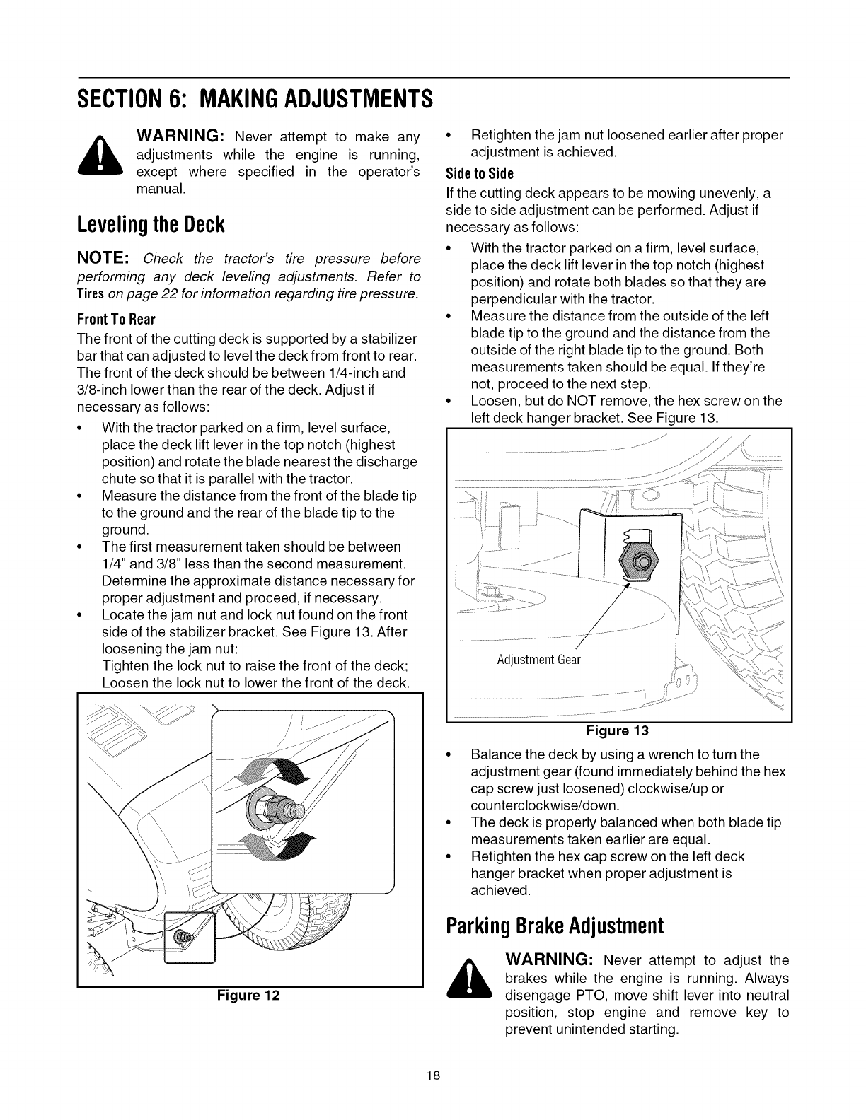
FrontTo Rear
The front of the cutting deck is supported by a stabilizer
bar that can adjusted to level the deck from front to rear.
The front of the deck should be between 1/4-inch and
3/8-inch lower than the rear of the deck. Adjust if
necessary as follows:
• With the tractor parked on a firm, level surface,
place the deck lift lever in the top notch (highest
position) and rotate the blade nearest the discharge
chute so that it is parallel with the tractor.
• Measure the distance from the front of the blade tip
to the ground and the rear of the blade tip to the
ground.
• The first measurement taken should be between
1/4" and 3/8" less than the second measurement.
Determine the approximate distance necessary for
proper adjustment and proceed, if necessary.
• Locate the jam nut and lock nut found on the front
side of the stabilizer bracket. See Figure 13. After
loosening the jam nut:
Tighten the lock nut to raise the front of the deck;
Loosen the lock nut to lower the front of the deck.
Figure 12
• Retighten the jam nut loosened earlier after proper
adjustment is achieved.
Sideto Side
If the cutting deck appears to be mowing unevenly, a
side to side adjustment can be performed. Adjust if
necessary as follows:
• With the tractor parked on a firm, level surface,
place the deck lift lever in the top notch (highest
position) and rotate both blades so that they are
perpendicular with the tractor.
• Measure the distance from the outside of the left
blade tip to the ground and the distance from the
outside of the right blade tip to the ground. Both
measurements taken should be equal. If they're
not, proceed to the next step.
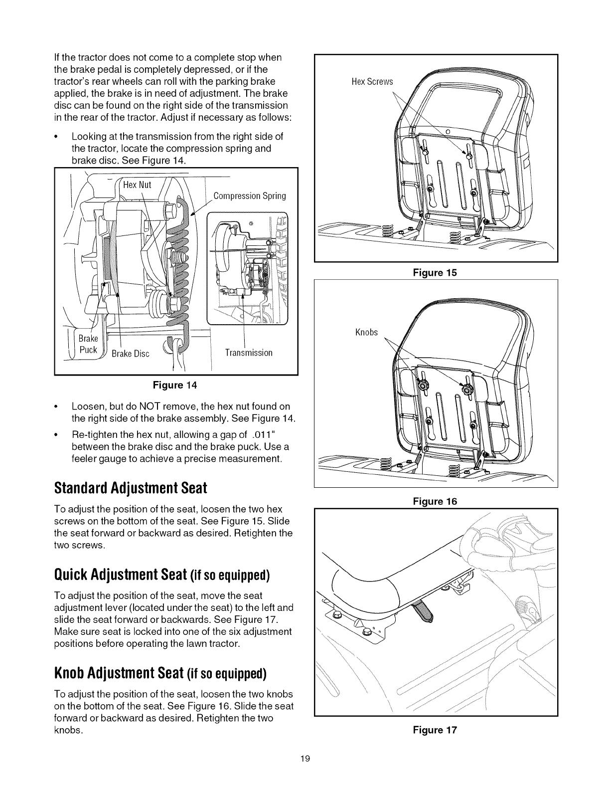
• Loosen, but do NOT remove, the hex screw on the
left deck hanger bracket. See Figure 13.
Adjustment Gear
Figure 13
• Balance the deck by using a wrench to turn the
adjustment gear (found immediately behind the hex
cap screw just loosened) clockwise/up or
counterclockwise/down.
• The deck is properly balanced when both blade tip
measurements taken earlier are equal.
• Retighten the hex cap screw on the left deck
hanger bracket when proper adjustment is
achieved.
ParkingBrakeAdjustment
WARNING: Never attempt to adjust the
brakes while the engine is running. Always
disengage PTO, move shift lever into neutral
position, stop engine and remove key to
prevent unintended starting.
18
If the tractor does not come to a complete stop when
the brake pedal is completely depressed, or if the
tractor's rear wheels can roll with the parking brake
applied, the brake is in need of adjustment. The brake
disc can be found on the right side of the transmission
in the rear of the tractor. Adjust if necessary as follows:
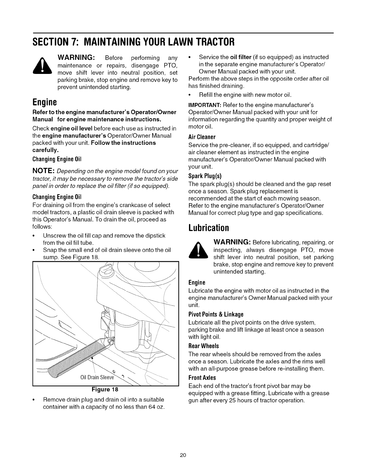
Looking at the transmission from the right side of
the tractor, locate the compression spring and
brake disc. See Figure 14.
\
Compression Spring
BrakeDisc
@
Transmission
Figure 14
• Loosen, but do NOT remove, the hex nut found on
the right side of the brake assembly. See Figure 14.
• Re-tighten the hex nut, allowing a gap of .011"
between the brake disc and the brake puck. Use a
feeler gauge to achieve a precise measurement.
StandardAdjustmentSeat
To adjust the position of the seat, loosen the two hex
screws on the bottom of the seat. See Figure 15. Slide
the seat forward or backward as desired. Retighten the
two screws.
QuickAdjustmentSeat(ifsoequipped)
To adjust the position of the seat, move the seat
adjustment lever (located under the seat) to the left and
slide the seat forward or backwards. See Figure 17.
Make sure seat is locked into one of the six adjustment
positions before operating the lawn tractor.
KnobAdjustmentSeat(if soequipped)
To adjust the position of the seat, loosen the two knobs
on the bottom of the seat. See Figure 16. Slide the seat
forward or backward as desired. Retighten the two
knobs.
HexScrews
Figure 15
Knobs
Figure 16
\
\
Figure 17
19
SECTION7: MAINTAININGYOURLAWNTRACTOR
WARNING: Before performing any
maintenance or repairs, disengage PTO,
move shift lever into neutral position, set
parking brake, stop engine and remove key to
prevent unintended starting.
Engine
Refer to the engine manufacturer's Operator/Owner
Manual for engine maintenance instructions.
Check engine oil level before each use as instructed in
the engine manufacturer's Operator/Owner Manual
packed with your unit. Follow the instructions
carefully.
Changing EngineOil
NOTE: Depending on the engine model found on your
tractor, it may be necessary to remove the tractor's side
panel in order to replace the oil filter (if so equipped).
Changing EngineOil
For draining oil from the engine's crankcase of select
model tractors, a plastic oil drain sleeve is packed with
this Operator's Manual. To drain the oil, proceed as
follows:
Unscrew the oil fill cap and remove the dipstick
from the oil fill tube.
Snap the small end of oil drain sleeve onto the oil
sump. See Figure 18.
Figure 18
Remove drain plug and drain oil into a suitable
container with a capacity of no less than 64 oz.
• Service the oil filter (if so equipped) as instructed
in the separate engine manufacturer's Operator/
Owner Manual packed with your unit.
Perform the above steps in the opposite order after oil
has finished draining.
• Refill the engine with new motor oil.
IMPORTANT:Refer to the engine manufacturer's
Operator/Owner Manual packed with your unit for
information regarding the quantity and proper weight of
motor oil.
Air Cleaner
Service the pre-cleaner, if so equipped, and cartridge/
air cleaner element as instructed in the engine
manufacturer's Operator/Owner Manual packed with
your unit.
SparkPlug(s)
The spark plug(s) should be cleaned and the gap reset
once a season. Spark plug replacement is
recommended at the start of each mowing season.
Refer to the engine manufacturer's Operator/Owner
Manual for correct plug type and gap specifications.
Lubrication
WARNING: Before lubricating, repairing, or
inspecting, always disengage PTO, move
shift lever into neutral position, set parking
brake, stop engine and remove key to prevent
unintended starting.
Engine
Lubricate the engine with motor oil as instructed in the
engine manufacturer's Owner Manual packed with your
unit.
PivotPoints& Linkage
Lubricate all the pivot points on the drive system,
parking brake and lift linkage at least once a season
with light oil.
RearWheels
The rear wheels should be removed from the axles
once a season. Lubricate the axles and the rims well
with an all-purpose grease before re-installing them.
Front Axles
Each end of the tractor's front pivot bar may be
equipped with a grease fitting. Lubricate with a grease
gun after every 25 hours of tractor operation.
20
CleaningtheEngineAndDeck
Any fuel or oil spilled on the machine should be wiped
off promptly. Do NOT allow debris to accumulate
around the cooling fins of the engine or on any other
part of the machine.
IMPORTANT:The use of a pressure washer to clean
your tractor is NOT recommended. It may cause
damage to electrical components, spindles, pulleys,
bearings or the engine.
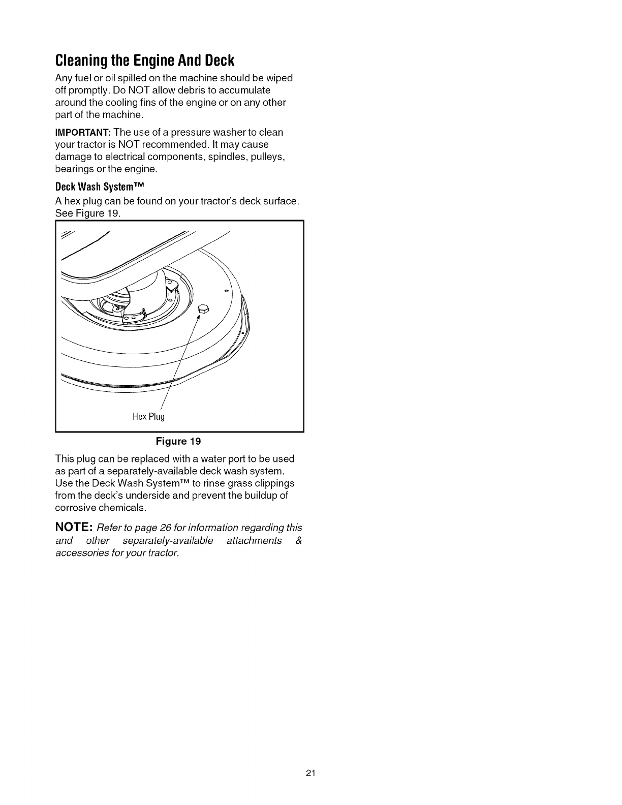
DeckWash SystemTM
A hex plug can be found on your tractor's deck surface.
See Figure 19.
HexPlug
Figure 19
This plug can be replaced with a water port to be used
as part of a separately-available deck wash system.
Use the Deck Wash System TM to rinse grass clippings
from the deck's underside and prevent the buildup of
corrosive chemicals.
NOTE: Refer to page 26 for information regarding this
and other separately-available attachments &
accessories for your tractor.
21
SECTION8: SERVICE
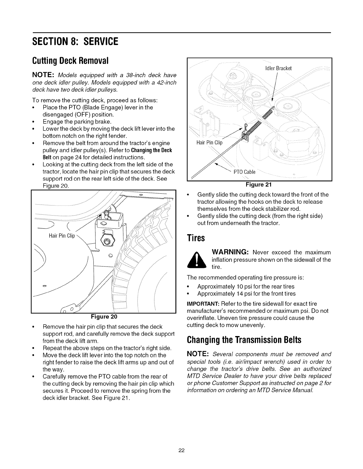
CuttingDeckRemoval
NOTE: Models equipped with a 38-inch deck have
one deck idler pulley. Models equipped with a 42-inch
deck have two deck idler pulleys.
To remove the cutting deck, proceed as follows:
• Place the PTO (Blade Engage) lever in the
disengaged (OFF) position.
• Engage the parking brake.
• Lower the deck by moving the deck lift lever into the
bottom notch on the right fender.
• Remove the belt from around the tractor's engine
pulley and idler pulley(s). Refer to Changingthe Beck
Belton page 24 for detailed instructions.
• Looking at the cutting deck from the left side of the
tractor, locate the hair pin clip that secures the deck
support rod on the rear left side of the deck. See
Figure 20.
/
/
Figure 20
• Remove the hair pin clip that secures the deck
support rod, and carefully remove the deck support
from the deck lift arm.
• Repeat the above steps on the tractor's right side.
• Move the deck lift lever into the top notch on the
right fender to raise the deck lift arms up and out of
the way.
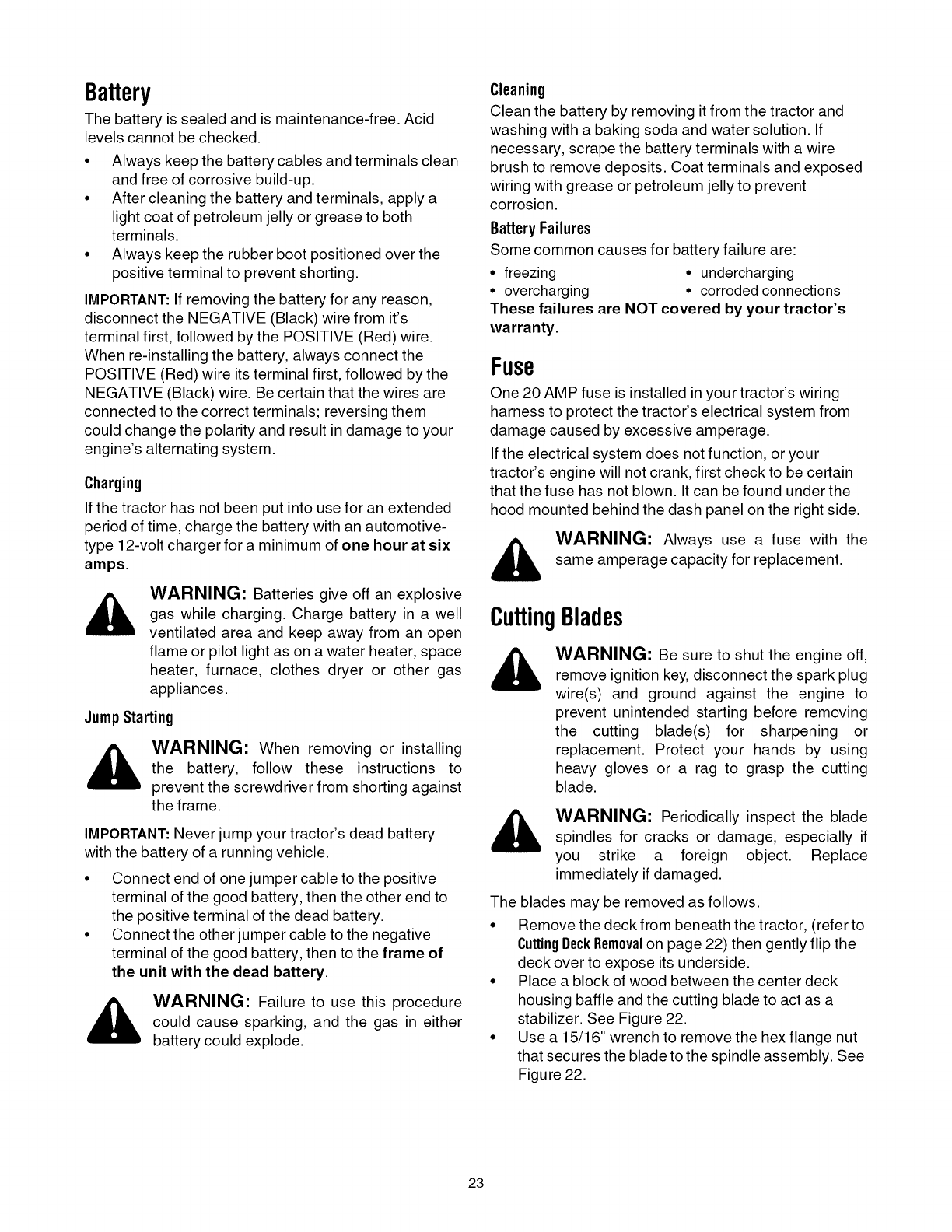
• Carefully remove the PTO cable from the rear of
the cutting deck by removing the hair pin clip which
secures it. Proceed to remove the spring from the
deck idler bracket. See Figure 21.
IdlerBracket
f
t
Hair Pin Clip
'- PTOCable
Figure 21
• Gently slide the cutting deck toward the front of the
tractor allowing the hooks on the deck to release
themselves from the deck stabilizer rod.
• Gently slide the cutting deck (from the right side)
out from underneath the tractor.
Tires
_, WARNING: Never exceed the maximum
inflation pressure shown on the sidewall of the
tire.
The recommended operating tire pressure is:
• Approximately 10 psi for the rear tires
• Approximately 14 psi for the front tires
IMPORTANT: Refer to the tire sidewall for exact tire
manufacturer's recommended or maximum psi. Do not
overinflate. Uneven tire pressure could cause the
cutting deck to mow unevenly.
ChangingtheTransmissionBelts
NOTE: Several components must be removed and
special tools (i.e. air/impact wrench) used in order to
change the tractor's drive belts. See an authorized
MTD Service Dealer to have your drive belts replaced
or phone Customer Support as instructed on page 2 for
information on ordering an MTD Service Manual
22
Battery
The battery is sealed and is maintenance-free. Acid
levels cannot be checked.
• Always keep the battery cables and terminals clean
and free of corrosive build-up.
• After cleaning the battery and terminals, apply a
light coat of petroleum jelly or grease to both
terminals.
• Always keep the rubber boot positioned over the
positive terminal to prevent shorting.
IMPORTANT: If removing the battery for any reason,
disconnect the NEGATIVE (Black) wire from it's
terminal first, followed by the POSITIVE (Red) wire.
When re-installing the battery, always connect the
POSITIVE (Red) wire its terminal first, followed by the
NEGATIVE (Black) wire. Be certain that the wires are
connected to the correct terminals; reversing them
could change the polarity and result in damage to your
engine's alternating system.
Charging
If the tractor has not been put into use for an extended
period of time, charge the battery with an automotive-
type 12-volt charger for a minimum of one hour at six
amps.
WARNING: Batteries give off an explosive
gas while charging. Charge battery in a well
ventilated area and keep away from an open
flame or pilot light as on a water heater, space
heater, furnace, clothes dryer or other gas
appliances.
JumpStarting
_ WARNING: When removing or installing
the battery, follow these instructions to
prevent the screwdriver from shorting against
the frame.
IMPORTANT: Never jump your tractor's dead battery
with the battery of a running vehicle.
• Connect end of one jumper cable to the positive
terminal of the good battery, then the other end to
the positive terminal of the dead battery.
• Connect the other jumper cable to the negative
terminal of the good battery, then to the frame of
the unit with the dead battery.
WARNING: Failure to use this procedure
could cause sparking, and the gas in either
battery could explode.
Cleaning
Clean the battery by removing it from the tractor and
washing with a baking soda and water solution. If
necessary, scrape the battery terminals with a wire
brush to remove deposits. Coat terminals and exposed
wiring with grease or petroleum jelly to prevent
corrosion.
BatteryFailures
Some common causes for battery failure are:
•freezing • undercharging
• overcharging • corroded connections
These failures are NOT covered by your tractor's
warranty.
Fuse
One 20 AMP fuse is installed in your tractor's wiring
harness to protect the tractor's electrical system from
damage caused by excessive amperage.
If the electrical system does not function, or your
tractor's engine will not crank, first check to be certain
that the fuse has not blown. It can be found under the
hood mounted behind the dash panel on the right side.
_, ARNING: Always use a fuse with the
same amperage capacity for replacement.
CuttingBlades
WARNING: Be sure to shut the engine off,
remove ignition key, disconnect the spark plug
wire(s) and ground against the engine to
prevent unintended starting before removing
the cutting blade(s) for sharpening or
replacement. Protect your hands by using
heavy gloves or a rag to grasp the cutting
blade.
_, ARNING: Periodically inspect the bladespindles for cracks or damage, especially if
you strike a foreign object. Replace
immediately if damaged.
The blades may be removed as follows.
• Remove the deck from beneath the tractor, (refer to
CuttingDeckRemovalon page 22) then gently flip the
deck over to expose its underside.
• Place a block of wood between the center deck
housing baffle and the cutting blade to act as a
stabilizer. See Figure 22.
• Use a 15/16" wrench to remove the hex flange nut
that secures the blade to the spindle assembly. See
Figure 22.
23
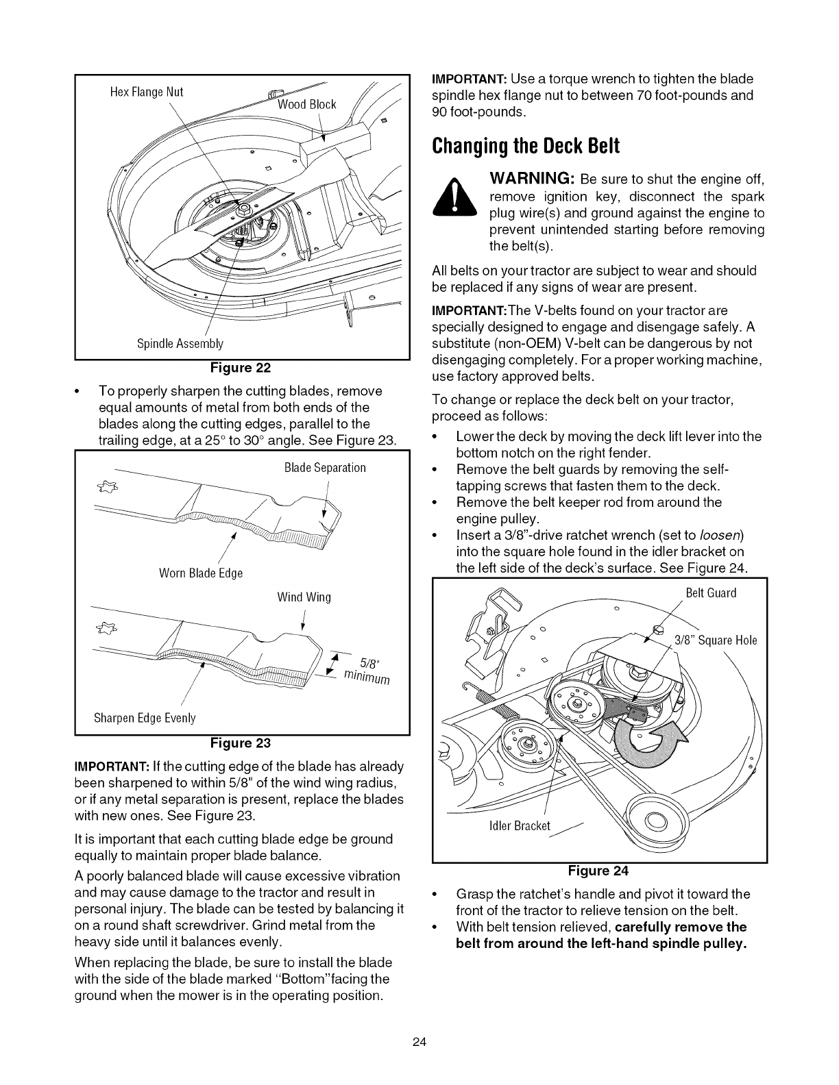
HexFlangeNut
SpindleAssembly
Figure 22
To properly sharpen the cutting blades, remove
equal amounts of metal from both ends of the
blades along the cutting edges, parallel to the
trailing edge, at a 25 °to 30° angle. See Figure 23.
Blade Separation
/
/
WornBladeEdge
Wind Wing
/
SharpenEdgeEvenly
Figure 23
IMPORTANT: Ifthe cutting edge of the blade has already
been sharpened to within 5/8" of the wind wing radius,
or if any metal separation is present, replace the blades
with new ones. See Figure 23.
It is important that each cutting blade edge be ground
equally to maintain proper blade balance.
A poorly balanced blade will cause excessive vibration
and may cause damage to the tractor and result in
personal injury. The blade can be tested by balancing it
on a round shaft screwdriver. Grind metal from the
heavy side until it balances evenly.
When replacing the blade, be sure to install the blade
with the side of the blade marked "Bottom"facing the
ground when the mower is in the operating position.
IMPORTANT:Use a torque wrench to tighten the blade
spindle hex flange nut to between 70 foot-pounds and
90 foot-po unds.
ChangingtheDeckBelt
WARNING: Be sure to shut the engine off,
remove ignition key, disconnect the spark
plug wire(s) and ground against the engine to
prevent unintended starting before removing
the belt(s).
All belts on your tractor are subject to wear and should
be replaced if any signs of wear are present.
IMPORTANT:The V-belts found on your tractor are
specially designed to engage and disengage safely. A
substitute (non-OEM) V-belt can be dangerous by not
disengaging completely. For a proper working machine,
use factory approved belts.
To change or replace the deck belt on your tractor,
proceed as follows:
• Lower the deck by moving the deck lift lever into the
bottom notch on the right fender.
• Remove the belt guards by removing the self-
tapping screws that fasten them to the deck.
• Remove the belt keeper rod from around the
engine pulley.
• Insert a 3/8"-drive ratchet wrench (set to loosen)
into the square hole found in the idler bracket on
the left side of the deck's surface. See Figure 24.
BeltGuard
Idler Bracket_
Figure 24
• Grasp the ratchet's handle and pivot it toward the
front of the tractor to relieve tension on the belt.
• With belt tension relieved, carefully remove the
belt from around the left-hand spindle pulley.
24
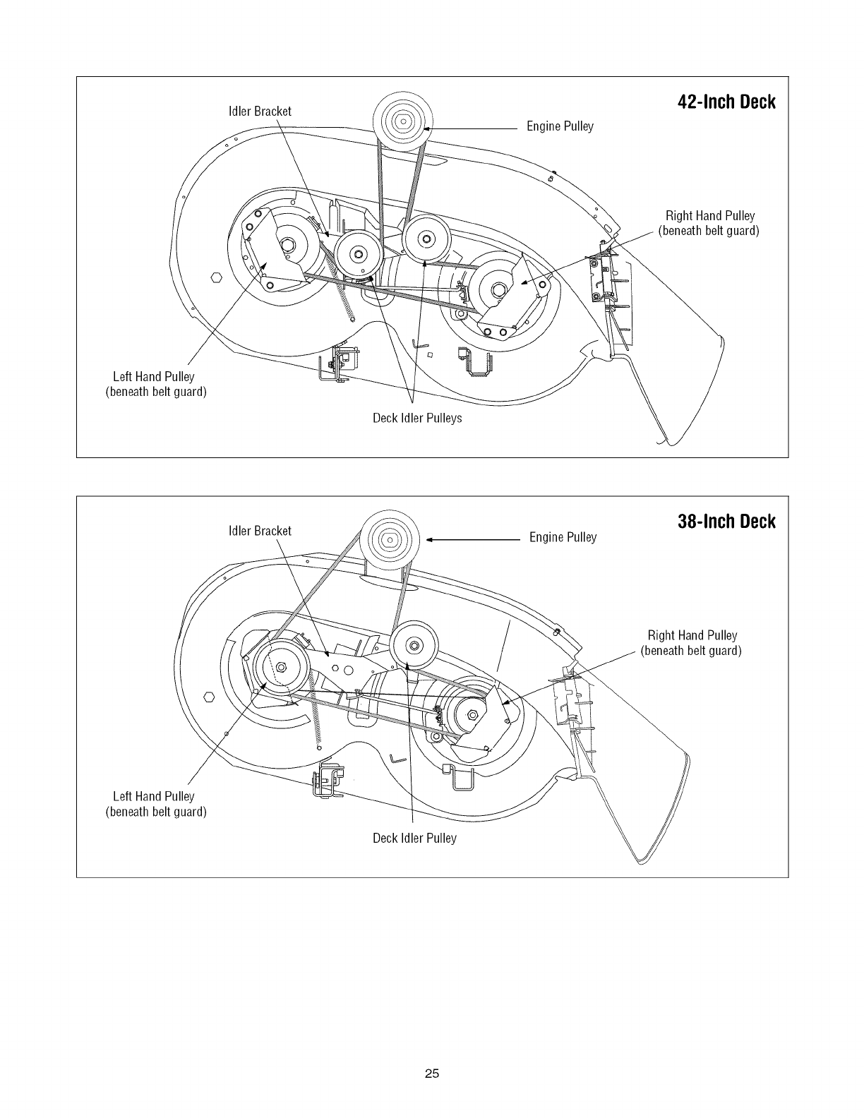
IdlerBracket 42-Inch Deck
EnginePulley
Right Hand Pulley
(beneath belt guard)
©
Left Hand Pulley
(beneath belt guard)
Deck Idler Pulleys
Idler Bracket EnginePulley 38-Inch Deck
/Right Hand Pulley
(beneath belt guard)
Left Hand Pulley
(beneath belt guard)
Deck Idler Pulley
25
SECTION9: OFF-SEASONSTORAGE
Clean and lubricate the tractor as instructed in Section7:
MAINTAININGYOURLAWNTRACTORon page 20 of this
manual before storing for an extended period.
WARNING: Drain fuel only into an
approved container outdoors, away from an
open flame. Allow engine to cool. Extinguish
cigarettes, cigars, pipes, and other sources of
ignition prior to draining fuel.
Follow the instructions in the Service, Storage &
Specifications section of the engine manufacturer's
Operator/Owner Manual for proper engine care prior to
storing your tractor.
WARNING: Never store the machine or
fuel container indoors where there is an open
flame, spark or pilot light such as on water
heater, furnace, clothes dryer or other gas
appliance.
SECTION10: ATTACHMENTS& ACCESSORIES
The following attachments and accessories are compatible for 700-Series Lawn Tractors. See the retailer from
which you purchased your tractor, an authorized MTD Service Dealer or phone 1-800-800-7310 for information
regarding price and availability.
NOTE: Model Series 700 Lawn Tractors are NOT designed for use with any type of ground-engaging attachments
(e.g. tiller or plow). Use of this type of equipment WILL void the tractor's warranty.
MODEL
OEM-190-116
0EM-190-672
OEM-190-180
OEM-190-183
OEM-190-184
0EM-190-218
OEM-190-658
OEM-190-032
OEM-190-833
490-900-0024
490-900-0025
DESCRIPTION
38- and 42-inch Deck Mulch Kit
Grille Guard (mounts on front of tractor)
Twin Bagger Grass Collector
Deck Wheel Kit
Dethatcher
Rear Wheel Weights
Tire Chains
42-inch Two-stage Snow Thrower
46-inch Front Dozer Blade
Deluxe Tractor Sunshade
Deck Wash Kit
*Not compatible with tractors equipped with a Grass Collector
26
SECTION11: TROUBLESHOOTING
Trouble
Engine fails to start
Engine runs erratic
Possible Cause(s)
PTO engaged.
Parking brake not engaged.
Spark plug wire(s) disconnected.
Throttle control lever not in correct
starting position.
Choke not activated
Fuel tank empty, or stale fuel.
Blocked fuel line.
Faulty spark plug.
Engine flooded.
Unit running with CHOKE applied.
Spark plug wire(s) loose.
Blocked fuel line or stale fuel.
Vent in gas cap plugged.
Water or dirt in fuel system.
Dirty air cleaner.
Engine overheats Engine oil level low.
Air flow restricted.
Engine hesitates at high RPM Spark plug(s) gap too close.
Idles poorly Spark plug(s) fouled, faulty or gap too
wide.
Dirty air cleaner.
Excessive vibration
Mower will not mulch grass
Cutting blade loose or unbalanced.
Damaged or bent cutting blade.
Engine speed too low.
Wet grass.
Excessively high grass.
Dull blade.
Uneven cut Deck not balanced properly.
Dull blade.
Uneven tire pressure.
Corrective Action
Place PTO lever in disengaged (OFF) position.
Engage parking brake.
Connect wire(s) to spark plug(s).
Place throttle control in FAST position or CHOKE posi-
tion, if present.
Place the throttle control in CHOKE position or pull the
CHOKE knob outward.
Fill tank with clean, fresh (less than 30 days old) gas.
Clean fuel line or replace fuel filter, if so equipped.
Clean, adjust gap or replace plug.
Crank engine with throttle in FAST position.
Move the throttle control out of the CHOKE position or
push the CHOKE knob inward.
Connect and tighten spark plug wire(s).
Clean fuel line; fill tank with clean, fresh (less than 30
days old) gasoline. Replace fuel filter, if so equipped.
Clear vent or replace cap if damaged.
Drain fuel tank. Refill with clean, fresh (less than 30
days old) gasoline.
Replace air cleaner cartridge/element or clean pre-
cleaner, if so equipped.
Fill crankcase with proper capacity and weight of oil.
Clean grass clippings and debris from around the
engine's cooling fins and blower housing.
Remove spark plug(s) and reset the gap.
Replace spark plug(s). Set plug(s) gap.
Replace air cleaner cartridge/element or clean pre-
cleaner, if so equipped.
Tighten blade and spindle. Balance blade.
Replace blade.
Place throttle control in FAST (rabbit) position.
Do not mow when grass is wet; wait until later to cut.
Mow once at a high cutting height, then mow again at
desired height or make a narrower cutting swath.
Sharpen or replace blade.
Perform side-to-side deck adjustment.
Sharpen or replace blade.
Check tire pressure in all four tires.
27

MANUFACTURER'S LIMITED WARRANTY FOR:
The limited warranty set forth below is given by MTD LLC with
respect to new merchandise purchased and used in the
United States, its possessions and territories.
"MTD"warrants this product against defects in material and
workmanship for a period of two (2) years commencing on the
date of original purchase and will, at its option, repair or
replace, free of charge, any part found to be defective in
materials or workmanship. This limited warranty shall only
apply if this product has been operated and maintained in
accordance with the Operator's Manual furnished with the
product, and has not been subject to misuse, abuse,
commercial use, neglect, accident, improper maintenance,
alteration, vandalism, theft, fire, water, or damage because of
other peril or natural disaster. Damage resulting from the
installation or use of any part, accessory or attachment not
approved by MTD for use with the product(s) covered by this
manual will void your warranty as to any resulting damage.
Normal wear parts are warranted to be free from defects in
material and workmanship for a period of thirty (30) days from
the date of purchase. Normal wear parts include, but are not
limited to items such as: batteries, belts, blades, blade
adapters, grass bags, rider deck wheels, seats, snow thrower
skid shoes, shave plates, auger spiral rubber and tires.
HOW TO OBTAIN SERVICE: Warranty service is available,
WITH PROOF OF PURCHASE, through your local authorized
service dealer. To locate the dealer in your area, check your
Yellow Pages, or contact MTD LLC at P.O. Box 361131,
Cleveland, Ohio 44136-0019, or call 1-800-800-7310 or 1-
330-220-4683 or log on to our Web site at
www.mtdproducts.com.
This limited warranty does not provide coverage in the
following cases:
a. The engine or component parts thereof. These items
may carry a separate manufacturer's warranty. Refer
to applicable manufacturer's warranty for terms and
conditions.
b. Log splitter pumps, valves, and cylinders have a
separate one year warranty.
c. Routine maintenance items such as lubricants, filters,
blade sharpening, tune-ups, brake adjustments, clutch
adjustments, deck adjustments, and normal
deterioration of the exterior finish due to use or
exposure.
d. Service completed by someone other than an
authorized service dealer.
e,
f,
g.
MTD does not extend any warranty for products sold or
exported outside of the United States, its possessions
and territories, except those sold through MTD's
authorized channels of export distribution.
Replacement parts that are not genuine MTD parts.
Transportation charges and service calls.
No implied warranty, including any implied warranty of
merchantability of fitness for a particular purpose,
applies after the applicable period of express written
warranty above as to the parts as identified. No other
express warranty, whether written or oral, except as
mentioned above, given by any person or entity,
including a dealer or retailer, with respect to any product,
shall bind MTD. During the period of the warranty, the
exclusive remedy is repair or replacement of the product
as set forth above.
The provisions as set forth in this warranty provide the
sole and exclusive remedy arising from the sale. MTD
shall not be liable for incidental or consequential loss or
damage including, without limitation, expenses incurred
for substitute or replacement lawn care services or for
rental expenses to temporarily replace a warranted
product.
Some states do not allow the exclusion or limitation of
incidental or consequential damages, or limitations on how
long an implied warranty lasts, so the above exclusions or
limitations may not apply to you.
In no event shall recovery of any kind be greater than the
amount of the purchase price of the product sold. Alteration
of safety features of the product shall void this warranty.
You assume the risk and liability for loss, damage, or injury to
you and your property and/or to others and their property
arising out of the misuse or inability to use the product.
This limited warranty shall not extend to anyone other than the
original purchaser or to the person for whom it was purchased
as a gift.
HOW STATE LAW RELATES TO THIS WARRANTY: This
limited warranty gives you specific legal rights, and you may
also have other rights which vary from state to state.
IMPORTANT:Owner must present Original Proof of
Purchase to obtain warranty coverage.
MTD LLC, P.O.BOX361131CLEVELAND,OHIO44136-0019; Phone:1-800-800-7310,1-330-220-4683
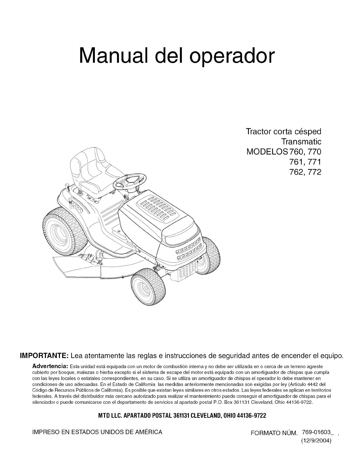
Manual del operador
Tractor corta cesped
Transmatic
MODELOS 760, 770
761,771
762,772
IMPORTANTE: Lea atentamente las reglas e instrucciones de seguridad antes de encender el equipo.
Advertencia: Esta unidad esta equipada con un motor de combusti6n intema y no debe ser utilizada en o cerca de un terreno agreste
cubierto por bosque, malezas o hierba excepto si el sistema de escape del motor esta equipado con un amortiguador de chispas que cumpla
con las leyes locales o estatales correspondientes, en su caso, Si se utiliza un amortiguador de chispas el operador Io debe mantener en
condiciones de uso adecuadas, En el Estado de California las medidas anteriormente mencionadas son exigidas por ley (Articulo 4442 del
C6digo de Recursos Pt_blicos de California), Es posible que existan leyes similares en otros estados, Las leyes federales se aplican en territorios
federales, A traves del distribuidor mas cercano autorizado para realizar el mantenimiento puede conseguir el amortiguador de chispas para el
silenciador o puede comunicarse con el departamento de servicios al apartado postal P,O, Box 361131 Cleveland, Ohio 44136-9722,
MTD LLC.APARTADOPOSTAL361131CLEVELAND,OHIO44136-9722
IMPRESO EN ESTADOS UNIDOS DE AME_RICA FORMATO NOM. 769-01603_ ,
(12/9/2004)
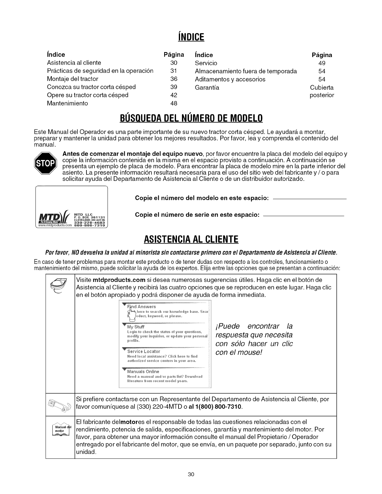
JNDICE
Jndice P_gina
Asistencia al cliente 30
Pra.cticas de seguridad en la operaci6n 31
Montaje del tractor 36
Conozca su tractor corta cesped 39
Opere su tractor corta cesped 42
Mantenimiento 48
Jndice P_gina
Servicio 49
Almacenamiento fuera de temporada 54
Aditamentos y accesorios 54
Garanta Cubierta
posterior
BUSQUEDADELNUMERODE MODELO
Este Manual del Operador es una parte importante de su nuevo tractor corta cesped. Le ayudara, a montar,
preparar y mantener la unidad para obtener los mejores resultados. Por favor, lea y comprenda el contenido del
manual.
Antes de comenzar el montaje del equipo nuevo, por favor encuentre la placa del modelo del equipo y
copie la informaci6n contenida en la misma en el espacio provisto a continuaci6n. A continuaci6n se
presenta un ejemplo de placa de modelo. Para encontrar la placa de modelo mire en la parte inferior del
asiento. La presente informaci6n resultara, necesaria para el uso del sitio web del fabricante y /o para
solicitar ayuda del Departamento de Asistencia al Cliente o de un distribuidor autorizado.
_')(( MTDLLC
P. O. BOX 361131
CLEVELAND,OH 44136
330-220-4683
www, mtdproducts.corn 800-800-7310
Copie el ndmero del modelo en este espacio:
Copie el ndmero de serie en este espacio:
ASISTENClAAL CLIENTE
Porfavor, NOdevuelva/a unidadal minoristasincontactarseprimero conel Departamentode Asistenciaal Cfiente.
En caso de tener problemas para montar este producto o detener dudas con respecto a loscontroles, funcionamiento o
mantenimiento del mismo,puede solicitar la ayuda de los expertos. Elija entre las opciones que se presentan a continuaci6n:
Ma ual d I
Visite mtdproducts.com si desea numerosas sugerencias t_tiles. Haga clic en el bot6n de
Asistencia al Cliente y recibira, las cuatro opciones que se reproducen en este lugar. Haga clic
en el bot6n apropiado y podra, disponer de ayuda de forma inmediata.
TFl_nd Answers
i_=J@A_Ic_ Re_w_r_l @_jAurase
iPuede encontrar la
respuesta que necesita
con s51o hacer un clic
con el mouse!
Si prefiere contactarse con un Representante del Departamento de Asistencia al Cliente, por
favor comun[quese al (330) 220-4MTD o al 1(800) 800-7310.
El fabricante delmotores el responsable de todas las cuestiones relacionadas con el
rendimiento, potencia de salida, especificaciones, garantia y mantenimiento del motor. Por
favor, para obtener una mayor informaci6n consulte el manual del Propietario /Operador
entregado por el fabricante del motor, que se envia, en un paquete por separado, junto con su
unidad.
3O
SECCION1: PRACTICASDESEGURIDADENLAOPERACION
ADVERTENCIA: La presencia de este simbolo indica que se trata de instrucciones importantes de seguridad
que debe respetar para evitar poner en riesgo su seguridad personal y /o material y de otras personas. Lea y siga
todas las instrucciones en este manual antes de iniciar la operaci6n de esta m_tquina.En caso de no seguir estas
instrucciones podria provocar lesionespersonales. Cuando vea este simbolo--siga la advertencia.
PELIGRO: Esta ma.quina fue construida para set operada de acuerdo con las reglas de seguridad en la
operaci6n contenidas en este manual. AI igual que con cualquier tipo de equipo electrico, un descuido o
error de parte del operador puede producir lesiones graves. Esta ma.quina es capaz de amputar manos y
pies y de arrojar objetos con gran fuerza. De no respetar las instrucciones de seguridad siguientes se
pueden producir lesiones graves o la muerte.
Advertencia, Proposicibn 65 de California:
ADVERTENClA: El escape del motor de este producto, algunos de sus componentes y algunos
componentes del vehiculo contienen o emiten productos quimicos que el estado de California considera
que pueden producir ca.ncer, defectos de nacimiento u otros problemas reproductivos.
FUNCIONAMIENTO GENERAL:
1. Lea, comprenda y respete todas las instrucciones
que figuran en la ma.quina o en este(os)
manual(es) antes de proceder al ensamblado y
operaci6n del equipo. Guarde este manual en un
lugar seguro para consultas futuras y regulates y
para solicitar repuestos.
2. Familiar[cese con todos los controles y con el uso
adecuado de los mismos. Sepa c6mo detener la
ma.quina y c6mo desengranar los controles
ra.pidamente.
3. Nunca permita que niSos menores de 14 aSos
operen esta ma.quina. Los niSos de 14 aSos y ma.s
deben leer y comprender las instrucciones de
operaci6n y las reglas de seguridad contenidas en
este manual y deben set capacitados y
supervisados por uno de los padres.
4. Nunca permita que adultos sin los conocimientos
adecuados acerca de la ma.quina la operen.
5. Para ayudar a evitar el contacto con las cuchillas o
una lesi6n por algt_n objeto que sea arrojado,
mantenga alas personas que Io observan, a los
ayudantes, niSos y mascotas alejados al menos 25
metros de la ma.quina mientras esta. en
funcionamiento. Detenga la ma.quina si alguien
traspasa este radio de seguridad.
6. Revise minuciosamente la zona donde se utilizara.
el equipo. Retire todas las piedras, palos, Ilantas,
huesos, juguetes y otros objetos extraSos que
podr[an ser recogidos y arrojados por la acci6n de
las cuchillas. Los objetos arrojados por la ma.quina
pueden producir lesiones graves.
7. Planifique el patr6n de poda para evitar que la
descarga de material se realice hacia los caminos,
las veredas, los observadores, etc. Evite adema.s
descargar material contra las paredes y
obstrucciones que podrian provocar que el material
descargado rebote contra el operador.
8. Para protegerse los ojos utilice siempre gafas o
lentes de seguridad mientras opera la ma.quina o
mientras la ajusta o repara. Los objetos arrojados
que rebotan pueden lesionar gravemente la vista.
9. Utilice zapatos de trabajo resistentes, de suela
fuerte y pantalones y camisas ajustados. Las
prendas sueltas o las alhajas pueden quedar
atrapadas en las piezas movibles. Nunca opere
esta ma.quina estando descalzo o con sandalias.
10. Este atento de la podadora y de la direcci6n de la
descarga de los aditamentos y no apunte a nadie.
Nunca opere esta podadora sin que esten en su
lugar apropiado la cubierta de descarga o bolsa
recolectora de cesped.
11. No ponga las manos ni los pies cerca de las piezas
rotatorias ni debajo de la cubierta de code. El
contacto con las cuchillas puede producir la
amputaci6n de manos y pies.
12. Una cubierta de descarga faltante o daSada puede
provocar lesiones por contacto con la cuchilla o por
objetos arrojados.
13. Detenga las cuchillas cuando cruce caminos de
gravilla, pasillos o caminos y cuando no este
cortando el cesped.
14. Vigile el tra.nsito vehicular cuando este operando
cerca de o en cruces de caminos. Esta ma.quina no
debe utilizarse en la via pt_blica.
15. No opere esta ma.quina estando bajo los efectos
del alcohol o de drogas.
16. Corte el cesped solamente con luz de dia o con
una buena luz artificial.
17. Nunca transporte pasajeros.
18. Desenganche las cuchillas antes de colocar
reversa. Retroceda lentamente. Siempre mire
hacia abajo y atras antes y mientras va en reversa,
para evitar un accidente.
19. Reduzca la velocidad antes de girar. Opere la
ma.quina suavemente. Evite la operaci6n erra.tica y
la velocidad excesiva.
20. Desenganche las cuchillas, coloque el freno de
mano, detenga el motor y espere hasta que las
cuchillas se detengan pot completo antes de retirar
el colector de recortes de cesped, vaciar los
recortes, destapar la tolva, retirar cualquier residuo
o desecho, o hacer cualquier ajuste.
21. Nunca deje la ma.quina en funcionamiento sin
vigilancia. Apague siempre las cuchillas, coloque la
transmisi6n en neutral, coloque el freno de mano,
detenga el motor y retire la Ilave antes de bajarse
del vehiculo.
22. Tenga cuidado al cargar o descargar la ma.quina en
un cami6n. Esta unidad no debe conducirse en
ascenso o descenso de rampas, porque podria
ladearse y provocar lesiones personales graves.
Debe empujar manualmente la unidad en la tampa
para cargarla o descargarla apropiadamente.
31
23. El silenciador y el motor se calientan y pueden
producir quemaduras. No los toque.
24. Revise los espacios por encima de la cabeza antes de
conducir bajo las ramas bajas de los _trboles,cables,
cerramientos de puertas, etc. en donde el operador
podria atorarse o ser empujado fuera de la unidad, Io que
podria resultaren lesiones graves.
25. Desenganche todos los embragues de
aditamentos, presione el pedal de frenos
completamente y cambie a neutral antes de
intentar arrancar el motor.
26. Su m_tquinafue diseSada para cortar cesped residencial
normal, con una altura no mayor a 10". No intente cortar
cesped demasiado crecido, seco (pastura) o pilas de
hojas secas. Elcesped y las hojas secas pueden entrar
encontacto con elescape del motor y/o acumularse en la
cubierta de la podadora, convirtiendose en un peligro de
incendio
27. Utilice solamente partes y accesorios fabricados
especialmente para esta ma.quina, originales del
fabricante. Lea, comprenda y siga todas las
instrucciones proporcionadas con los accesorios o
aditamentos aprobados.
28. Los datos estad[sticos muestran que los
conductores mayores de 60 aSos seven
involucrados en un alto porcentaje de lesiones
relacionadas con tractores corta cesped. Estos
operadores deben evaluar su capacidad para
operar el tractor corta cesped en forma
suficientemente segura para protegerse a ellos
mismos y a los dema.s contra lesiones graves.
29. Si se presentan situaciones que no esta.n previstas
en este manual sea cuidadoso y use el sentido
comt_n. Contacte al centro autorizado de servicio
MTD para obtener ayuda.
FUNCIONAMIENTO EN PENDIENTES
Las pendientes son unfactor importante que se relaciona con
accidentes de derrapes y caidas que pueden producir
lesiones graves e incluso la muerte. La operaci6n en
pendientes requiere mayor precauci6n. Si no puede
retroceder en la pendiente o no siente que sea f_tcil,no pode
ale
Para seguridad, use el medidor de pendientes que se incluye
como parte de este manual para medir la pendiente antes de
operar la unidad en unazona inclinada. Si lapendiente es
mayor a 15grados en el medidor, no opere esta unidad en
esa Area,pues podria causar lesiones graves.
HAGA LO SIGUIENTE:
1. Pode hacia arriba y abajo de las pendientes, no en
forma transversal. Tenga cuidado cuando cambie
de direcci6n al operar la ma.quina en pendientes.
2. Este atento a los agujeros, ra[ces, rocas, objetos
ocultos o abultamientos que puedan provocar que
se derrape o se tropiece. El terreno desnivelado
puede voltear la ma.quina. El cesped alto puede
oc uItar obsta.culos.
3. Vaya a baja velocidad. Elija una velocidad Io
suficientemente baja, de modo que no tenga que
detenerse o hacer cambios mientras esta. sobre la
pendiente. Las Ilantas podr[an perder tracci6n
sobre las pendientes aunque los frenos funcionen
apropiadamente. Siempre mantenga la ma.quina
con una velocidad seleccionada en la palanca
mientras desciende las pendientes para poder
frenar con motor.
4. Siga la recomendaci6n del fabricante para los
32
pesos o contrapesos de las ruedas, para mejorar la
estabilidad de la ma.quina.
5. Tenga especial cuidado con los colectores de
recorte de cesped u otros aditamentos. Estos
pueden modificar la estabilidad de la ma.quina.
6. Haga que todos los movimientos en las pendientes sean
lentosy graduales. No cambie repentinamente la
velocidad ni la direcci6n. Unfrenado ocambio de
velocidad repentinospueden causar que el frente de la
m_tquinase levantey de unavoltereta hacia atr_ts,Io que
podria producir lesionesseveras.
7. Evite arrancar o detenerse en una pendiente. Si los
neuma.ticos pierden la tracci6n, desenganche las
cuchillas y descienda lentamente la pendiente.
NO:
1. No gire sobre las pendientes a menos que sea
necesario. Si es as[, de vuelta lenta y
gradualmente descendiendo de la pendiente, si es
posible.
2. No corte el cesped cerca de pozos, hundimientos,
bancos, podria perder el equilibrio. La podadora podria
volcarse repentinamente si una de las Ilantas estuviera
fuera del borde de unpozo, banco u agujero.
3. No intente estabilizar la ma.quina poniendo su pie
en el piso.
4. No utilice un colector de cesped en pendientes
escalonadas.
5. No pode el cesped ht_medo. Una menortracci6n
podr[a causar derrapes.
6. No haga cambios a neutral para descender. El
exceso de velocidad podr[a hacer que el operador
pierda el control de la ma.quina, ocasionando
lesiones graves e incluso la muerte.
7. No arrastre cargas pesadas detr_tsde los aditamentos
(carritode basura cargado, podadora de rodillos, etc.) en
pendientes mayores de 5 grados. Cuando descienda, el
peso adicional tiende a empujar eltractor y podria
ocasionar que usted pierda el control. (eltractor podria
acelerarse, reduciendo lacapacidad defrenando y
maniobrabilidad, los aditamentos podrian clavarse y
hacer palanca y provocar que el tractor se voltee).
NII_IOS
,Pueden ocurrir accidentes tra.gicos si el operador
no esta. atento a la presencia de niSos. Por Io
general a los niSos les atraen las podadoras y la
actividad de podar el cesped. No entienden los
riesgos ni los peligros. Nunca asuma que los niSos
permanecera.n en el mismo lugar donde los vio por
Wtima vez.
a. Mantenga a los niSos fuera del Area de
trabajo y bajo estricta vigilancia de un adulto
responsable adema.s del operador.
b. Este alerta y apague la podadora si un niSo
ingresa al Area.
c. Antes y mientas se esta. retrocediendo, mire
hacia atra.s y cuide que no haya niSos.
d. Nunca transporte niSos, at_ncon la cuchilla
apagada. Podr[an caerse y resultar
severamente lesionados o interferir con la
operaci6n segura de la ma.quina.
e. Tenga extrema precauci6n cuando se
aproxime a esquinas ciegas, entradas de
puertas, a.rboles u otros objetos que puedan
obstaculizarle la vista de un niSo que
pudiese chocar con la ma.quina.
f. Para evitar accidentes al operar en
marcha atr_s, desenganche las cuchillas
antes de colocar reversa. El "Modo de
Precauci6n en Reversa" no debe
utilizarse cuando est_n presentes nihos u
otras personas.
g. Mantenga a los ni_os alejados de los motores en
marcha ocalientes. Puedensufrir quemaduras
con un silenciador caliente.
h. Retire la Ilave cuando deje la ma.quina sin
vigilancia, para impedir que una persona sin
autorizaci6n la maneje.
Nunca permita que los niSos menores de 14 aSos
operen esta ma.quina. Los niSos mayores de 14
aSos deben leer y entender las instrucciones de
operaci6n y reglas de seguridad contenidas en
este manual y deben set entrenados y
supervisados por sus padres.
,
ARRASTRE
1. Realice arrastres t_nicamente utilizando una
ma.quina que cuente con un dispositivo de
enganche diseSado para arrastrar objetos. Los
equipos a arrastrar deben conectarse t_nicamente
a la punta de enganche.
2. Siga las recomendaciones del fabricante en Io que
respecta a los limites de peso de los equipos a
arrastrar y al arrastre en pendientes.
3. Nunca permita la presencia de niSos u otras
personas dentro o sobre los equipos a arrastrar.
4. En pendientes, el peso del equipo a arrastrar
puede causar p@dida de tracci6n y p@dida de
control de la ma.quina.
5. Despla.cese lentamente, y guarde una distancia
extra para frenado.
6. No haga cambios a neutral para descender.
MANTENIMIENTO
MANEJO SEGURO DE LA GASOLINA
,Sea sumamente cuidadoso al manipular la
gasolinapara evitar lesiones o daSos. La gasolina
es altamente inflamable y sus vapores pueden
causar explosiones. Se puede lesionar gravemente
si derrama gasolina sobre usted o sobre la ropa, ya
que esta se puede incendiar. Lave la piel y
ca.mbiese de ropa de inmediato.
a. Utilice s61o recipientes para gasolina
autorizados.
b. Nunca Ilene los recipientes en el interior de
un veh[culo o cami6n o caja de camioneta
con recubrimientos pla.sticos. Coloque
siempre los recipientes en el piso y lejos del
vehiculo antes de Ilenarlos.
c. Cuando sea pra.ctico, retire el equipo a
gasolina del cami6n o remolque y Ilenelo en
el piso. Si esto no es posible, Ilene el equipo
en un remolque con contenedor porta.til, en
vez de desde un dispensador de gasolina.
d. Mantenga la boquilla de Ilenado en contacto
con el borde del tanque de gasolina o de la
abertura del recipiente en todo momento
hasta terminar la carga. No utilice un
dispositivo para abrir/cerrar la boquilla.
e. Apague todos los cigarrillos, cigarros, pipas
y otras fuentes de combusti6n.
f. Nunca cargue combustible en la ma.quina en
un espacio cerrado.
g. Nunca saque la tapa del combustible ni
agregue combustible mientras el motor esta.
caliente o en marcha. Deje que el motor se
enfrie pot Io menos dos minutos antes de
volver a cargar combustible.
h. Nunca Ilene en exceso el tanque de
combustible. Llene el tanque no ma.s de Y2
pulgada por debajo de la base del cuello del
filtro para dejar espacio para la dilataci6n del
combustible.
i. Vuelva a colocar la tapa de la gasolina y
ajustela bien.
j. Limpie el combustible que se derrame sobre
el motor y el equipo. Traslade la ma.quina a
otra zona. Espere 5 minutos antes de
encender el motor.
k. Para reducir el riesgo de incendio, mantenga
la ma.quina limpia de pasto, hojas y de
acumulaci6n de otros escombros. Limpie los
derrames de aceite o combustible y saque
todos los escombros embebidos con
combustible.
I. Nunca almacene la ma.quina o el recipiente
de combustible en un espacio cerrado donde
haya fuego, chispas o luz piloto como por
ejemplo, de calentadores de agua,
calefactores de ambientes, hornos,
secadores de ropa u otros aparatos a gas.
m. Deje que la ma.quina se enfr[e 5 minutos por
Io menos antes de almacenarla.
SERVIClO GENERAL:
1. Nunca encienda un motor en espacios cerrados o
en una zona con poca ventilaci6n. El escape del
motor contiene mon6xido de carbono, un gas
inodoro y letal.
2. Antes de limpiar, reparar o inspeccionar la
ma.quina, compruebe que la cuchilla y todas las
partes que se mueven se hayan detenido.
Desconecte el cable de la bujia y p6ngalo de
manera que haga masa contra el motor para evitar
que se encienda de manera accidental.
3. Revise peri6dicamente para asegurarse de que las
cuchillas se detengan por completo en un espacio de
aproximadamente cinco (5)segundos despu_s de
accionar el control de desenganche. Si las cuchillas no
se detienen en este lapso, su unidad debe ser reparada
por un profesional en un centro de servicio autorizado.
4. Revise con frecuencia el funcionamiento del
sistema de frenos ya que esta. sujeto a desgaste
por la operaci6n normal. Ajuste y efectt_e
mantenimiento segt_n se requiera.
5. Revise los pernos de montaje de la cuchilla y del
motor a intervalos frecuentes para verificar que
esten bien ajustados. Adema.s, inspeccione
visualmente la cuchilla en busca de daSos
(desgaste excesivo, abolladuras, rajaduras, etc)
Reemplace las cuchillas s61o con partes de los
fabricantes de equipos originales listadas en este
manual. "La utilizaci6n de partes que no cumplan
con las especificaciones de equipos originales
podria tenet como resultado un rendimiento
incorrecto, y adema.s la seguridad podria estar
comprometida"
6. Las cuchillas de las podadoras son muy afiladas y
podr[an cortarlo. Envuelva la cuchilla o utilice
guantes y extreme las precauciones cuando
efectt_e mantenimiento.
7. Mantenga todas las tuercas, pernos y tornillos bien
33
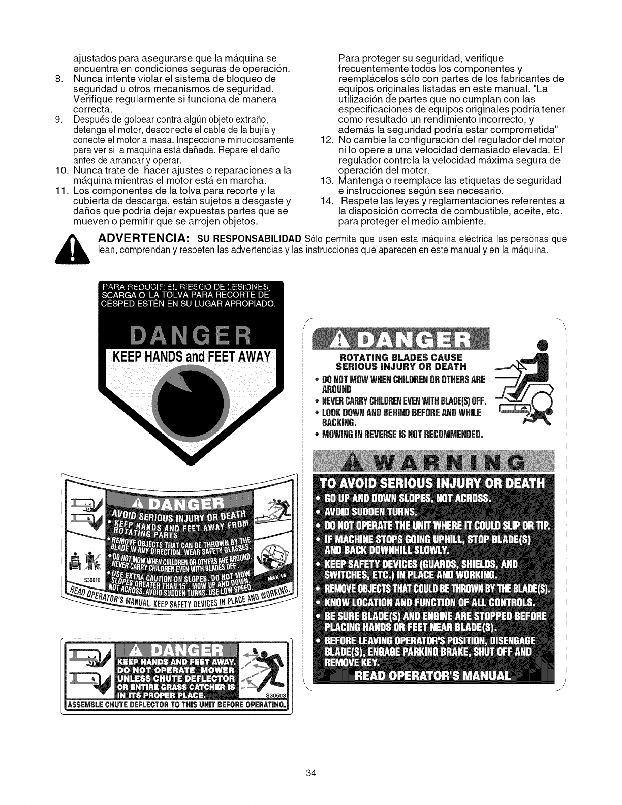
ajustados para asegurarse que la ma.quina se
encuentra en condiciones seguras de operaci6n.
8. Nunca intente violar el sistema de bloqueo de
seguridad u otros mecanismos de seguridad.
Verifique regularmente si funciona de manera
correcta.
9. Despu_s de golpear contra algQnobjeto extraSo,
detenga el motor, desconecte el cable de la bujia y
conecte el motora masa. Inspeccione minuciosamente
paraver si la m_tquinaesterdaSada. Repare el daSo
antes de arrancar y operar.
10. Nunca trate de hacer ajustes o reparaciones a la
ma.quina mientras el motor esta. en marcha.
11. Los componentes de la tolva para recorte y la
cubierta de descarga, esta.n sujetos a desgaste y
daSos que podria dejar expuestas partes que se
mueven o permitir que se arrojen objetos.
12.
13.
14.
Para proteger su seguridad, verifique
frecuentemente todos los componentes y
reempla.celos s61o con partes de los fabricantes de
equipos originales listadas en este manual. "La
utilizaci6n de partes que no cumplan con las
especificaciones de equipos originales podria tenet
como resultado un rendimiento incorrecto, y
adema.s la seguridad podria estar comprometida"
No cambie la configuraci6n del regulador del motor
ni Io opere a una velocidad demasiado elevada. El
regulador controla la velocidad maxima segura de
operaci6n del motor.
Mantenga o reemplace las etiquetas de seguridad
e instrucciones segt_n sea necesario.
Respete las leyes y reglamentaciones referentes a
la disposici6n correcta de combustible, aceite, etc.
para proteger el medio ambiente.
,_ ADVERTENClA: SU RESPONSABILIDAD $61opermita que usen esta m_tquinaelectrica las personas que
lean, comprendan y respeten las advertencias y las instrucciones que aparecen en este manual y en la m_tquina.
ROTAT|NG BLADESCAUSE
SI:RJOUS |HJURY OR DEATH
* DOHOTMOWWHENCHILDRENOROTHERSARE
AROUND
*NEVERCARRYCHILDRENEVENWiTHBLARE(S)OFFo
* LOOKDOWNAHBBEHINDBEFOREANDWHILE
BACKJHG.
* MOWIHGJHREVERSEiSHOTRECOMMEHBEB.
®
34
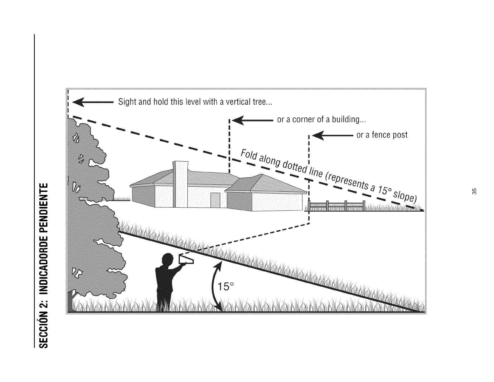
I,IJ
Z
I,IJ
!
r-_
Z
I.IJ
Q-
I.IJ
r-_
r-_
r-_
Z
Z
!
r_
r_
I.iJ
u3
Sight and hold this levelwith avertical tree...
|
I
|
|
or a fence post
I
15°
LO
CO
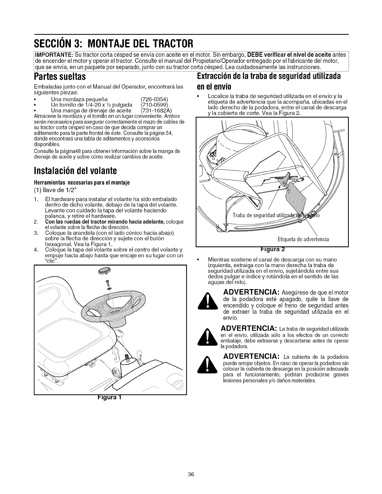
SECCION3: MONTAJEDELTRACTOR
IMPORTANTE: Su tractor corta cesped se envia con aceite en el motor. Sin embargo, DEBE verificar el nivel de aceite antes
de encender el motor y operar el tractor. Consulte el manual del Propietario/Operador entregado por el fabricante del motor,
que se envia, en un paquete por separado, junto con su tractor corta cesped. Lea cu dadosamente as nstrucc ones.
Partessueltas Extracci6ndela traba deseguridadutilizada
enelenvio
Embaladas junto con el Manual del Operador, encontrar& las
siguientes piezas:
° Una mordaza pequeSa (726-0354)
* Un tornillo de 1/4-20 x Y2pulgada (710-0599)
, Una manga de drenaje de aceite (731-1682A)
Alrnacene la rnordaza y el tornillo en un lugar conveniente. Arnbos
seran necesarios para asegurar correctarnente el rnazode cables de
su tractor corta c6sped en caso de que decida cornprar un
aditarnento para la parte frontal de 6ste. Consulte la pagina 54,
donde encontrara una tabla de aditarnentos y accesorios
disponibles.
Consulte la p_tgina48para obtener inforrnaci6n sobre la rnanga de
drenaje de aceite y sobre c6rno realizar carnbios de aceite.
Instalaci6ndelvolante
Herramientasnecesariasparael montaje
(1) Ilave de 1/2"
1. El hardware para instalar el volante ha sido embalado
dentro de dicho volante, debajo de la tapa del volante.
Levante con cuidado la tapa del volante haciendo
palanca, y retire el hardware.
2. Con las ruedas del tractor mirando hacia adelante, coloque
elvolante sobre la flecha dedirecci6n.
3. Coloque la arandela (con el lado c6nico hacia abajo)
sobre la flecha de direcci6n y sujete con el bul6n
hexagonal. Vea la Figura 1.
4. Coloque la tapa del volante sobre el centro del volante y
empuje hacia abajo hasta que encaje en su lugar con un
"clic".
Localice la traba de seguridad utilizada en el envio y la
etiqueta de advertencia que la acompa_a, ubicadas en el
lado derecho de la podadora, entre el canal de descarga
y la cubierta de corte. Vea la Figura 2.
Etiquetade advertencia
Ilgura 2
Mientras sostiene el canal de descarga con su mano
izquierda, extraiga con la mano derecha la traba de
seguridad utilizada en el envio, sujet_.ndola entre sus
dedos pulgar e indice y rotandola en el sentido de las
agujas del reloj.
ADVERTENClA: AsegQresede que el motor
de la podadora este apagado, quite la Ilave de
encendido y coloque el freno de seguridad antes
de extraer la traba de seguridad utilizada en el
envio.
_ DVERTENCIA: La traba de seguridad utilizada
en el envio, utilizada s61oa los efectos de un correcto
ernbalaje, debe extraerse y descartarse antes de operar
la podadora.
ADVERTENCIA: La cubierta de la podadora
puede arrojar objetos. Encaso de operar la podadora sin
colocar la cubierta de descarga en la posici6n adecuada
para el funcionarniento, podrian producirse graves
lesiones personales y/o daSos rnateriales.
PJgura 1
36
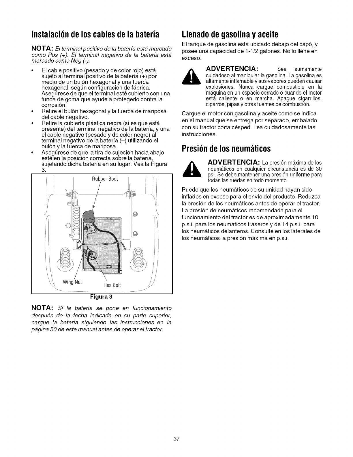
Instalaci6ndeloscablesdela bateria
NOTA: El terminal positivo de la baterfa esta marcado
como Pos (+). El terminal negativo de la baterfa esta
marcado como Neg (-).
• El cable positivo (pesado y de color rojo) esta.
sujeto al terminal positivo de la bater_a (+) por
medio de un bul6n hexagonal y una tuerca
hexagonal, segun configuraci6n de fa.brica.
Asegurese de que el terminal este cubierto con una
funda de goma que ayude a protegerlo contra la
corrosi6n.
• Retire el bul6n hexagonal y la tuerca de mariposa
del cable negativo.
• Retire la cubierta pla.stica negra (si es que esta.
presente) del terminal negativo de la bateria, y una
el cable negativo (pesado y de color negro) al
terminal negativo de la bateria (-) utilizando el
bul6n y la tuerca de mariposa.
• Asegurese de que la tira de sujeci6n hacia abajo
este en la posici6n correcta sobre la bateria,
sujetando dicha bater_a en su lugar. Vea la Figura
3.
Rubber Boot
/
Wing Nut HexBolt
Figura 3
NOTA: Si la baterfa se pone en funcionamiento
despues de la fecha indicada en su parte superior,
cargue la baterfa siguiendo las instrucciones en la
pagina 50 de este manual antes de operar el tractor.
Llenadodegasolinay aceite
El tanque de gasolina esta. ubicado debajo del cap6, y
posee una capacidad de 1-1/2 galones. No Io Ilene en
exceso.
ADVERTENCIA: Sea sumamente
cuidadoso al manipular la gasolina. La gasolina es
altamente inflamable y susvapores pueden causar
explosiones. Nunca cargue combustible en la
m_tquinaen un espacio cerrado o cuando el motor
ester caliente o en marcha. Apague cigarrillos,
cigarros, pipas y otras fuentes de combusti6n.
Cargue el motor con gasolina y aceite como se indica
en el manual que se entrega por separado, embalado
con su tractor corta cesped. Lea cuidadosamente las
instrucciones.
Presi6ndelosneum ticos
ADVERTENClA: La presi6n maxima de los
neumAticos en cualquier circunstancia es de 30
psi. Se debe mantener una presi6n uniforme para
todas las ruedas en todo momento.
Puede que los neuma.ticos de su unidad hayan sido
inflados en exceso para el env_o del producto. Reduzca
la presi6n de los neuma.ticos antes de operar el tractor.
La presi6n de neuma.ticos recomendada para el
funcionamiento del tractor es de aproximadamente 10
p.s.i, para los neuma.ticos traseros y de 14 p.s.i, para
los neuma.ticos delanteros. Consulte en los laterales de
los neuma.ticos la presi6n ma.xima en p.s.i.
37
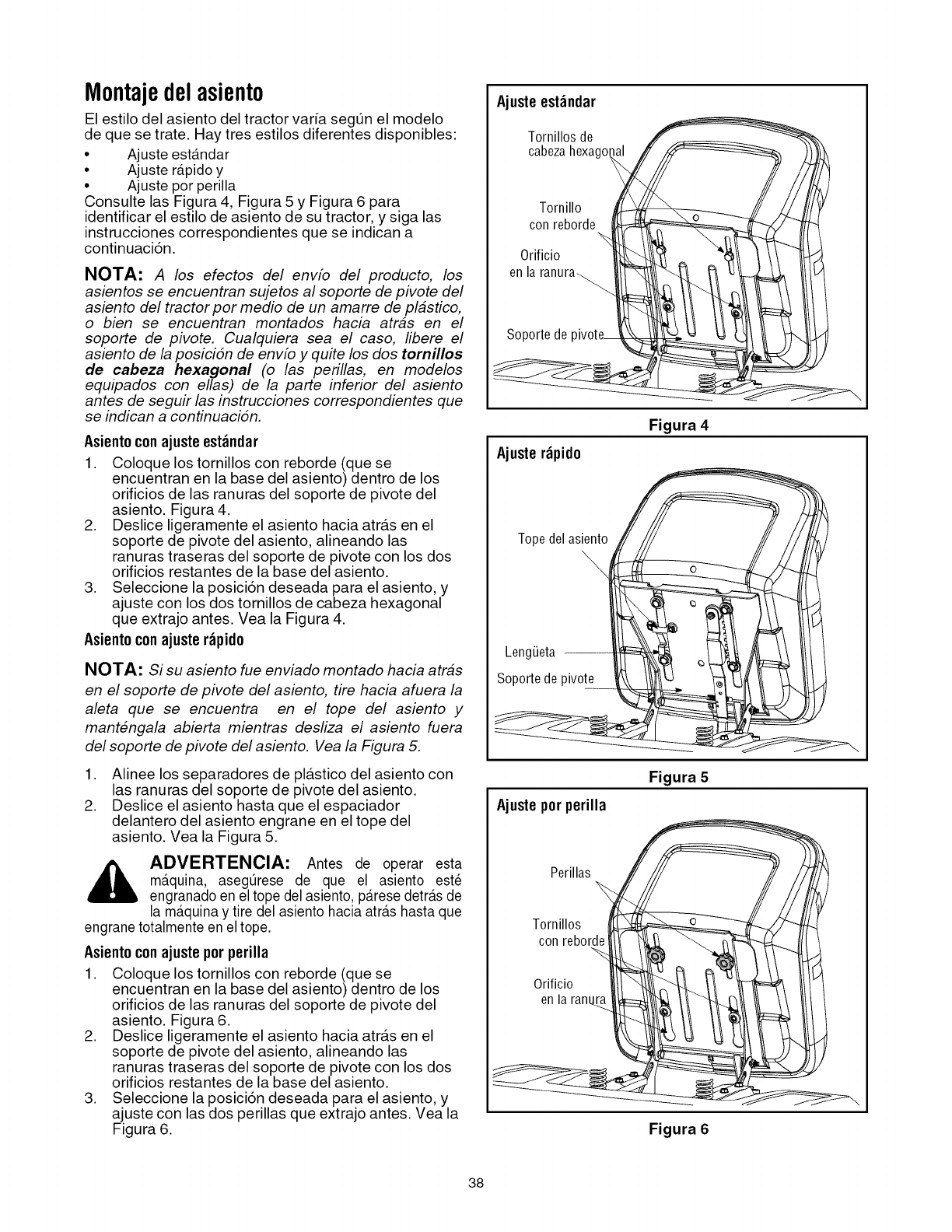
Montajedelasiento
El estilo del asiento del tractor varia segt_n el modelo
de que se trate. Hay tres estilos diferentes disponibles:
• Ajuste estandar
• Ajuste r_tpidoy
• Ajuste por perilla
Consulte las Figura 4, Figura 5 y Figura 6 para
identificar el estilo de asiento de su tractor, y siga las
instrucciones correspondientes que se indican a
continuaci6n.
NOTA: A los efectos del envfo del producto, los
asientos se encuentran sujetos al soporte de pivote del
asiento del tractor por medio de un amarre de pl#stico,
o bien se encuentran montados hacia atr#s en el
soporte de pivote. Cualquiera sea el caso, libere el
asiento de la posiciSn de envfo y qufe los dos tornillos
de cabeza hexagonal (o las perillas, en modelos
equipados con elias) de la parte inferior del asiento
antes de seguir las instrucciones correspondientes que
se indican a continuaciSn.
Asientoconajusteest_ndar
1. Coloque los tornillos con reborde (que se
encuentran en la base del asiento) dentro de los
orificios de las ranuras del soporte de pivote del
asiento. Figura 4.
2. Deslice ligeramente el asiento hacia atra.s en el
soporte de pivote del asiento, alineando las
ranuras traseras del soporte de pivote con los dos
orificios restantes de la base del asiento.
3. Seleccione la posici6n deseada para el asiento, y
ajuste con los dos tornillos de cabeza hexagonal
que extrajo antes. Vea la Figura 4.
Asientoconajuste r_pido
NOTA: Si su asiento fue enviado montado hacia atr#s
en el soporte de pivote del asiento, tire hacia afuera la
aleta que se encuentra en el tope del asiento y
mantengala abierta mientras desliza el asiento fuera
del soporte de pivote del asiento. Vea la Figura 5.
1. Alinee los separadores de pla.stico del asiento con
las ranuras del soporte de pivote del asiento.
2. Deslice el asiento hasta que el espaciador
delantero del asiento engrane en el tope del
asiento. Vea la Figura 5.
_DVERTENCIA: Antes de operar esta
m_tquina, asegQrese de que el asiento est_
engranado en el tope del asiento, p_tresedetr_tsde
la m_tquinay tire del asiento hacia atr_tshasta que
engrane totalmente en el tope.
Asientoconajuste por perilla
1. Coloque los tornillos con reborde (que se
encuentran en la base del asiento) dentro de los
orificios de las ranuras del soporte de pivote del
asiento. Figura 6.
2. Deslice ligeramente el asiento hacia atra.s en el
soporte de pivote del asiento, alineando las
ranuras traseras del soporte de pivote con los dos
orificios restantes de la base del asiento.
3. Seleccione la posici6n deseada para el asiento, y
ajuste con las dos perillas que extrajo antes. Vea la
Figura 6.
Ajusteest_ndar
Tornillosde
cabezahexagol
Tornillo
conreborde
0rificio
enla
Soporte de
Ajuster_pido
Figura 4
Topedelasiento
\
LengLieta
Soporte de pivote
Ajustepor perilla
Figura 5
Perillas
Tornillos
conreborde
0rificio
en la ranru_
Figura 6
38
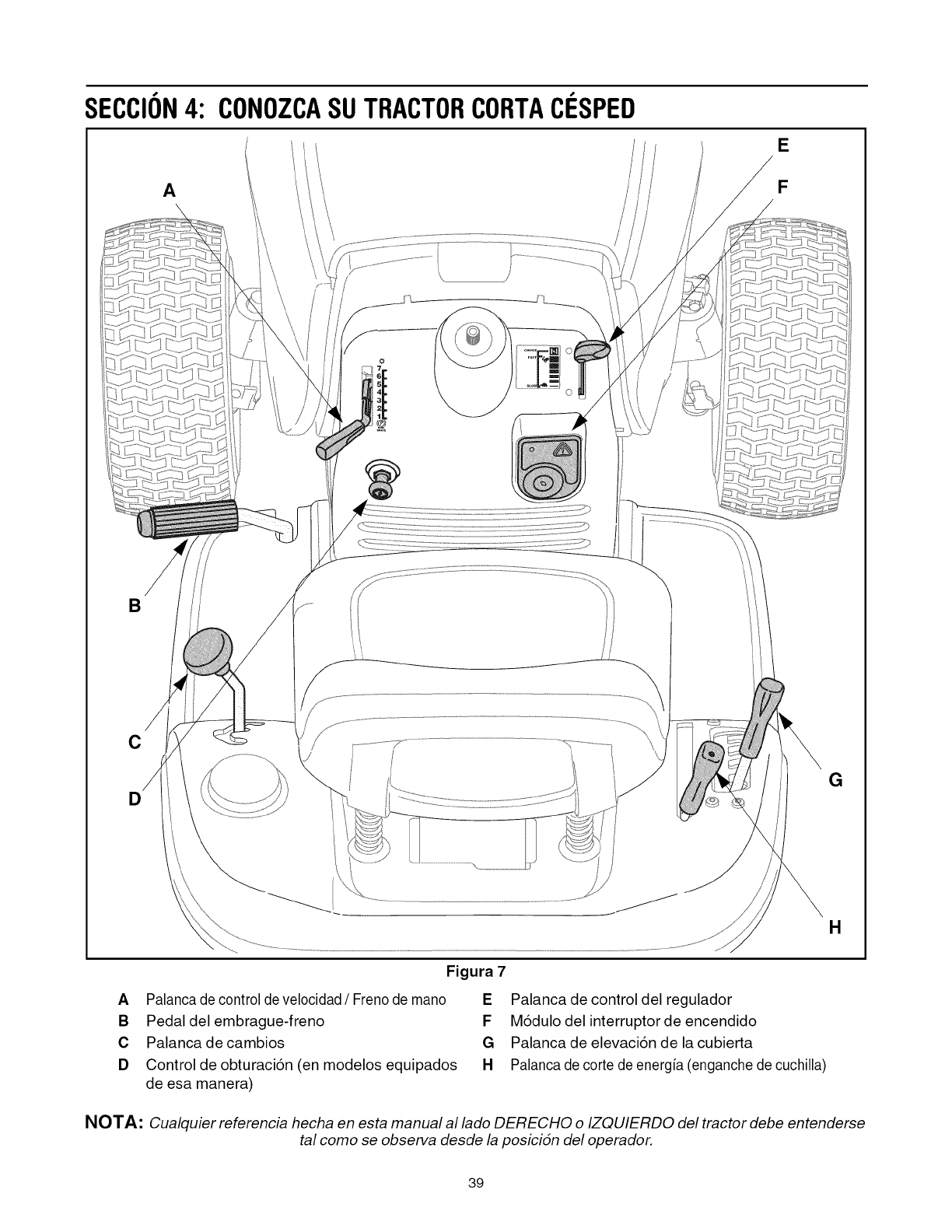
SECCION4: CONOZCASUTRACTORCORTAClaSPED
/
A
/
,/
///
/
E
F
B
C
D
\\
G
H
Figura 7
APalanca de control de velocidad /Freno de mano
B Pedaldel embrague-freno
C Palancadecambios
D Control de obturaci6n (en modelos equipados
de esa manera)
EPalanca de control del regulador
FM6dulo del interruptorde encendido
G Palanca de elevaci6n de la cubierta
H Palanca de corte de energia (enganche de cuchilla)
NOTA: Cualquier referencia hecha en esta manual al lado DERECHO o IZQUIERDO del tractor debe entenderse
tal como se observa desde la posicidn del operador.
39
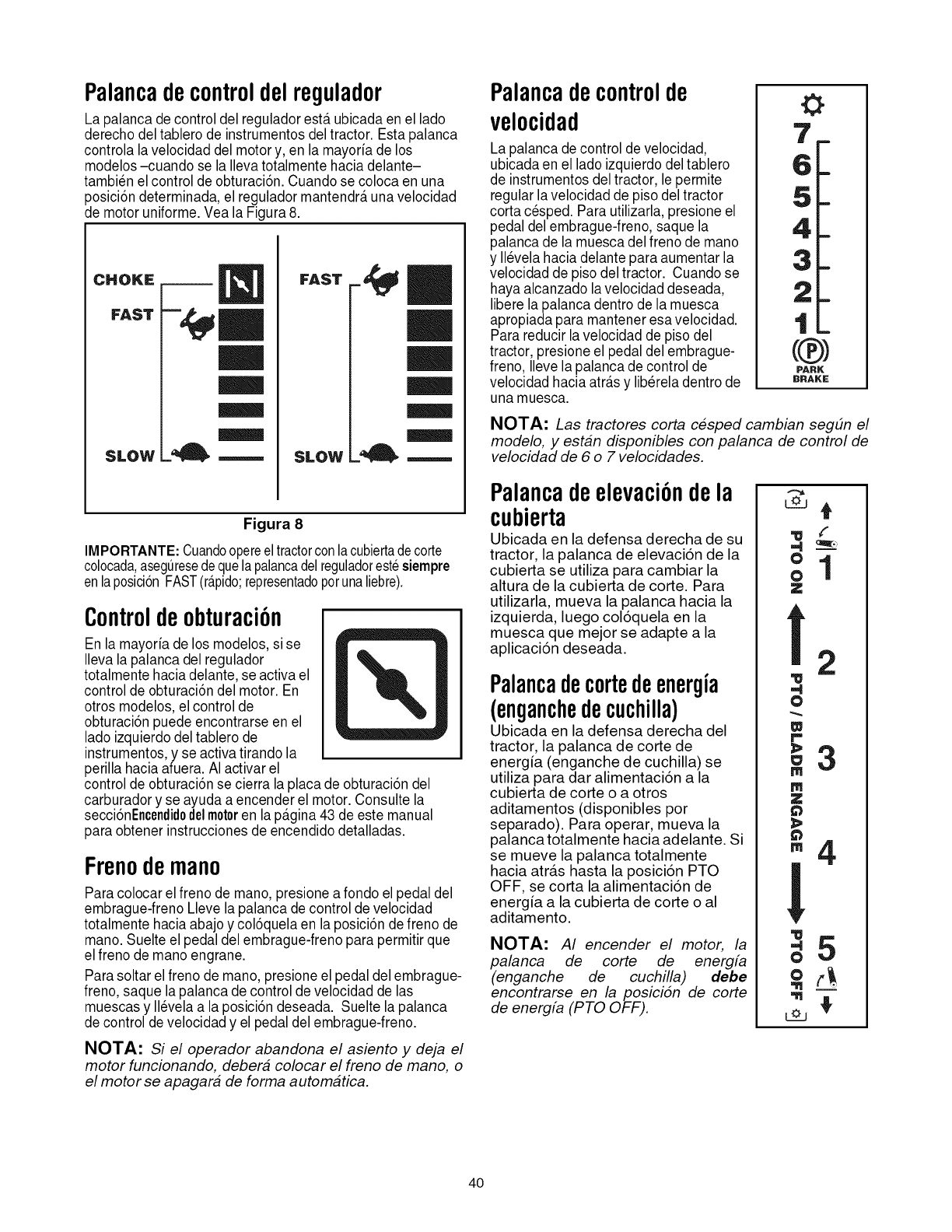
Palancadecontroldelreoulador
La palanca de control del regulador esta.ubicada en el lado
derecho deltablero de instrumentos deltractor. Esta palanca
controla la velocidad del motor y, en la mayoria de los
modelos -cuando se la Ilevatotalmente hacia delante-
tambien el control de obturaci6n. Cuando se coloca en una
posici6n determinada, el regulador mantendr_tuna velocidad
de motor uniforme. Vea la Figura 8.
CHOKE
FAST
SLOW
I
SLOW _'_ .=---.,
Figura 8
IMPORTANTE:Cuandoopereeltractorconlacubiertadecorte
colocada,aseguresedequelapalancadelreguladorestesiempre
enlaposicionFAST(r@ido;representadopotunaliebre).
Controldeobturaci6n
En la mayoria de los modelos, si se
Ileva la palanca del regulador
totalmente hacia delante, se activa el
control de obturaci6n del motor. En
otros modelos, el control de
obturaci6n puede encontrarse en el
lado izquierdo deltablero de
instrumentos,y se activa tirando la
perilla hacia afuera. AI activar el
control de obturaci6n se cierra la placa de obturaci6n del
carburador y se ayuda a encender el motor. Consulte la
secci6nEncendidodelmotoren la p_tgina43 de este manual
para obtener instruccionesde encendido detalladas.
Frenodemano
Para colocar el freno de mano, presione afondo elpedal del
embrague-freno Lleve la palanca de control develocidad
totalmente hacia abajoy col6quela en la posici6n de freno de
mano. Suelte el pedal del embrague-freno para permitir que
el freno de mano engrane.
Para soltar el freno de mano, presione el pedal del embrague-
freno, saque la palanca de control develocidad de las
muescas y Ilevelaa la posici6n deseada. Suelte la palanca
de control de velocidad y el pedal del embrague-freno.
NOTA: Si el operador abandona el asiento y deja el
motor funcionando, debera colocar el freno de mano, o
el motor se apagara de forma automatica.
Palancadecontrolde
velocidad
La palanca de control develocidad,
ubicada en el lado izquierdo del tablero
de instrumentos del tractor, le permite
regular lavelocidad de piso deltractor
corta cesped. Para utilizarla, presione el
pedal del embrague-freno, saque la
palanca de la muesca del freno de mano
y Ilevela hacia delante para aumentar la
velocidad de piso del tractor. Cuando se
haya alcanzado lavelocidad deseada,
libere la palanca dentro de la muesca
apropiada para mantener esa velocidad.
Para reducir lavelocidad de piso del
tractor, presione el pedal del embrague-
freno, Ilevela palanca de control de
velocidad hacia atr_tsy lib@eladentro de
una muesca.
O
(@)
PARK
BRAKE
NOTA: Las tractores corta cesped cambian segEm el
modelo, y estan disponibles con palanca de control de
velocidad de 6 o 7 velocidades.
Palancadeelevaci6ndela
cubierta
Ubicada en la defensa derecha de su
tractor, la palanca de elevaci6n de la
cubierta se utiliza para cambiar la
altura de la cubierta de code. Para
utilizarla, mueva la palanca hacia la
izquierda, luego col6quela en la
muesca que mejor se adapte a la
aplicaci6n deseada.
Palancadecortedeenergia
(enganchedecuchilla)
Ubicada en la defensa derecha del
tractor, la palanca de corte de
energ[a (enganche de cuchilla) se
utiliza para dar alimentaci6n a la
cubierta de corte o a otros
aditamentos (disponibles por
separado). Para operar, mueva la
palanca totalmente hacia adelante. Si
se mueve la palanca totalmente
hacia atra.s hasta la posici6n PTO
OFF, se corta la alimentaci6n de
energ[a a la cubierta de corte o al
aditamento.
NOTA: AI encender el motor, la
palanca de corte de energfa
(enganche de cuchilla) debe
encontrarse en la posiciSn de corte
de energfa (PTO OFF).
,.e4_.,
0
ol
Z
=4
O
w
r,,
m
Z
m
!
O
2
3
4
5
40
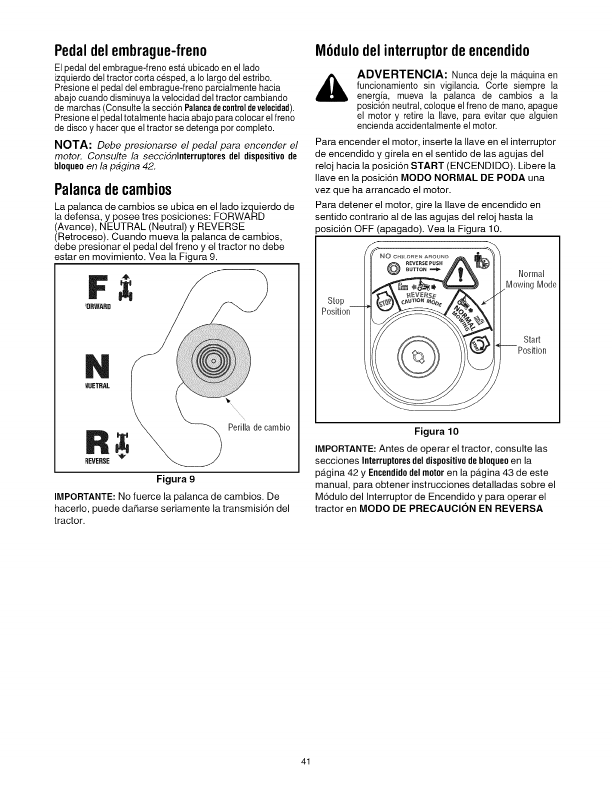
Pedaldelembrague-freno
El pedal del embrague-freno esterubicado en el lado
izquierdo deltractor corta cesped, a Io largo del estribo.
Presione el pedal del embrague-freno parcialmente hacia
abajo cuando disminuya lavelocidad del tractor cambiando
de marchas (Consulte lasecci6n Palancadecontroldevelocidad).
Presione el pedaltotalmentehacia abajo paracolocar el freno
de disco y hacer que eltractorse detenga porcompleto.
NOTA: Debe presionarse el pedal para encender el
motor. Consulte la seccidnlnterruptores del dispositiv0de
bl0que0en la pagina 42.
Palancadecambios
La palanca de cambios se ubica en el lado izquierdo de
la defensa, y posee tres posiciones: FORWARD
(Avance), NEUTRAL (Neutral) y REVERSE
(Retroceso). Cuando mueva la palanca de cambios,
debe presionar el pedal del freno y el tractor no debe
estar en movimiento. Vea la Figura 9.
4_
:ORWARD
MUETRAL
REVERSE
_'N,, R
Perilladecambio
Figura 9
IMPORTANTE: No fuerce la palanca de cambios. De
hacerlo, puede daSarse seriamente la transmisi6n del
tractor.
M6dulodelinterrupterdeencendido
ADVERTENCIA: Nunca deje la m_tquinaen
funcionamiento sin vigilancia. Corte siempre la
energia, mueva la palanca de cambios a la
posici6n neutral,coloque el freno de mano,apague
el motor y retire la Ilave, para evitar que alguien
encienda accidentalmente el motor.
Para encender el motor, inserte la Ilave en el interruptor
de encendido y girela en el sentido de las agujas del
reloj hacia la posici6n START (ENCENDIDO). Libere la
Ilave en la posici6n MODO NORMAL DE PODA una
vez que ha arrancado el motor.
Para detener el motor, gire la Ilave de encendido en
sentido contrario al de las agujas del reloj hasta la
_osici6n OFF (apagado). Vea la Figura 10.
Stop
Position
Normal
MowingMode
Start
Position
Figura 10
IMPORTANTE: Antes de operar el tractor, consulte las
secciones Interrupteresdeldispesitivodebloqueoen la
pa.gina 42 y Encendidodelmeteren la pa.gina 43 de este
manual, para obtener instrucciones detalladas sobre el
M6dulo del Interruptor de Encendido y para operar el
tractor en MODO DE PRECAUClON EN REVERSA
41
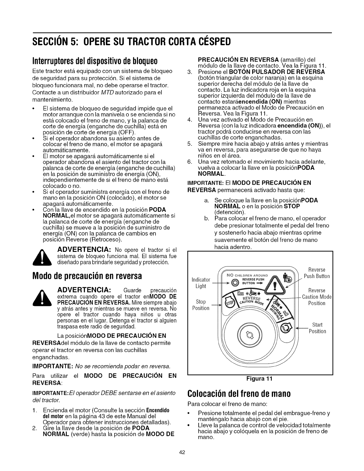
SECCION5: OPERESUTRACTORCORTAC[::SPED
Interruptoresdeldispositivodebloqueo
Este tractor esta. equipado con un sistema de bloqueo
de seguridad para su protecci6n. Si el sistema de
bloqueo funcionara mal, no debe operarse el tractor.
Contacte a un distribuidor MTD autorizado para el
mantenimiento.
• El sistema de bloqueo de seguridad impide que el
motor arranque con la manivela o se encienda si no
esta. colocado el freno de mano, y la palanca de
corte de energ[a (enganche de cuchilla) esta. en
posici6n de corte de energia (OFF).
• Si el operador abandona su asiento antes de
colocar el freno de mano, el motor se apagara.
automa.ticamente.
• El motor se apagara, automa.ticamente si el
operador abandona el asiento del tractor con la
palanca de corte de energ[a (enganche de cuchilla)
en la posici6n de suministro de energia (ON),
independientemente de si el freno de mano esta.
colocado o no.
• Si el operador suministra energia con el freno de
mano en la posici6n ON (colocado), el motor se
apagara, automa.ticamente.
• Con la Ilave de encendido en la posici6n PODA
NORMAL,el motor se apagara, automa.ticamente si
la palanca de corte de energia (enganche de
cuchilla) se mueve a la posici6n de suministro de
energ[a (ON) con la palanca de cambios en
posici6n Reverse (Retroceso).
ADVERTENClA: No opere el tractor si el
sistema de bloqueo funciona mal. El sistema fue
diseSado para brindarle seguridad y protecci6n.
Mododeprecauci6nenreversa
ADVERTENClA: Guarde precauci6n
extrema cuando opere el tractor enMODO DE
PREOAUOION EN REVERSA. Mire siempre abajo
y atr_tsantes y mientras se mueve en reversa. No
opere el tractor cuando haya niSos u otras
personas en el lugar. Detenga el tractor si alguien
traspasa este radio de seguridad.
La posici6nMODO DE PRECAUOION EN
REVERSAdel m6dulo de la Ilave de contacto permite
operar el tractor en reversa con las cuchillas
enganchadas.
IMPORTANTE: No se recomienda podar en reversa.
Para utilizar el MODO DE PRECAUClON EN
REVERSA:
IMPORTANTE:El operador DEBE sentarse en el asiento
del tractor.
1. Encienda el motor (Consulte la secci6n Encendido
delmotoren la pa.gina 43 de este Manual del
Operador para obtener instrucciones detalladas).
2. Gire la Ilave desde la posici6n de PODA
NORMAL (verde) hasta la posici6n de MODO DE
PRECAUClON EN REVERSA (amarillo) del
m6dulo de la Ilave de contacto. Vea la Figura 11.
3. Presione el BOTON PULSADOR DE REVERSA
(bot6n triangular de color naranja) en la esquina
superior derecha del m6dulo de la Ilave de
contacto. La luz indicadora roja en la esquina
superior izquierda del m6dulo de la Ilave de
contacto estara.encendida (ON) mientras
permanezca activado el Modo de Precauci6n en
Reversa. Vea la Figura 11.
4. Una vez activado el Modo de Precauci6n en
Reversa (con la luz indicadora encendida (ON)), el
tractor podra, conducirse en reversa con las
cuchillas de corte enganchadas.
5. Siempre mire hacia abajo y atra.s antes y mientras
va en reversa, para asegurarse de que no haya
ni_os en el Area.
6. Una vez retomado el movimiento hacia adelante,
vuelva a colocar la Ilave en la posici6nPODA
NORMAL.
IMPORTANTE: El MODO DE PRECAUClON EN
REVERSA permanecera, activado hasta que:
a.
b.
Se coloque la Ilave en la posici6nPODA
NORMAL o en la posici6n STOP
(detenci6n).
Para colocar el freno de mano, el operador
debe presionar totalmente el pedal del freno
y sostenerlo hacia abajo mientras oprime
suavemente el bot6n del freno de mano
hacia adentro.
Indicator
Light
Stop
Position
NO CHILDREN AROUND
REVERSE PUSH
BUTTON
Reverse
Push Button
Reverse
- Caution Mode
Position
Start
Position
Figura 11
Colocaci6ndelfrenodemano
Para colocar el freno de mano:
Presione totalmente el pedal del embrague-freno y
mantengalo hacia abajo con el pie.
Lleve la palanca de control de velocidad totalmente
hacia abajo y col6quela en la posici6n de freno de
mano.
42
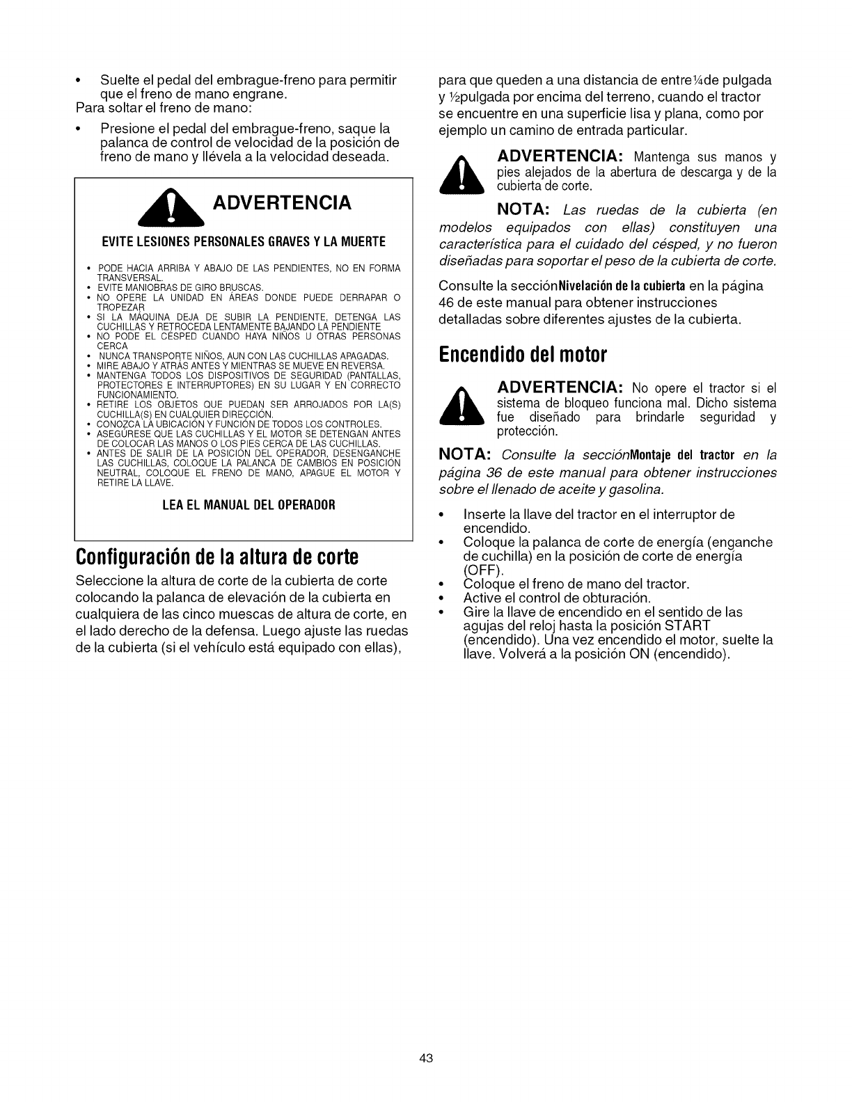
• Suelte el pedal del embrague-freno para permitir
que el freno de mano engrane.
Para soltar el freno de mano:
• Presione el pedal del embrague-freno, saque la
palanca de control de velocidad de la posici6n de
freno de mano y Ilevela a la velocidad deseada.
ADVERTENCIA
EVITELESIONESPERSONALESGRAVESYLAMUERTE
• PODE HACIA ARRIBA Y ABAJO DE LAS PENDIENTES, NO EN FORMA
TRANSVERSAL.
• EVlTE MANIOBRAS DE GIRO BRUSCAS.
• NO OPERE LA UNIDAD EN AREAS DONDE PUEDE DERRAPAR 0
TROPEZA.R
• SI LA MAQUINA DEJA DE SUBIR LA PENDIENTE, DETENGA LAS
CUCHILLAS Y RETROCEDA LENTAMENTE BAJANDO LA PENDIENTE
• NO PODE EL CE_SPED CUANDO HAYA NINOS U OTRAS PERSONAS
CERCA
• NUNCA TRANSPOR,TE NINOS, AUN CON LAS CUCHILLAS APAGADAS.
• MIRE ABAJO Y ATRAS ANTES Y MIENTRAS SE MUEVE EN REVERSA.
• MANTENGA TODOS LOS DISPOSITIVOS DE SEGURIDAD (PANTALLAS,
PROTECTORES E INTERRUPTORES) EN SU LUGAR Y EN CORRECTO
FUNCIONAMIENTO.
• RETIRE LOS OBJETOS ©UE PUEDAN SER ARROJADOS POR LA(S)
CUCHILLA(S) EN CUAL.QUIER DIRE.CCION.
• CONO.ZCA LA UBICACION Y FUNCION DE TODOS LOS CONTROLES.
• ASEGURESE QUE LAS CUCHILLAS Y EL MOTOR SE DETENGAN ANTES
DE COLOCAR LAS MANOS 0 LOS PIES CERCA DE LAS CUCHILLAS.
• ANTES DE SALIR DE LA POSICION DEL OPERADOR, DESENGANC.HE
LAS CUCHILLAS, COLOQUE LA PALANCA DE CAMBIOS EN POSICION
NEUTRAL, COLOQUE EL FRENO DE MANO, APAGUE EL MOTOR Y
RETIRE LA LLAVE.
LEAELMANUALDELOPERADOR
Configuraci6ndela alturadecorte
Seleccione la altura de corte de la cubierta de corte
colocando la palanca de elevaci6n de la cubierta en
cualquiera de las cinco muescas de altura de code, en
el lado derecho de la defensa. Luego ajuste las ruedas
de la cubierta (si el veh[culo esta. equipado con elias),
para que queden a una distancia de entrel_de pulgada
yY2pulgada por encima del terreno, cuando el tractor
se encuentre en una superficie lisa y plana, como por
ejemplo un camino de entrada particular.
ADVERTENCIA: Mantenga sus manos y
pies alejados de la abertura de descarga y de la
cubierta de corte.
NOTA: Las ruedas de la cubierta (en
modelos equipados con elias) constituyen una
caracterfstica para el cuidado del cesped, y no fueron
dise#adas para soportar el peso de la cubierta de corte.
Consulte la secci6nNivelaci6n dela cubiertaen la pa.gina
46 de este manual para obtener instrucciones
detalladas sobre diferentes ajustes de la cubierta.
Encendidodelmotor
_, ADVERTENClA: No opere el tractor si el
sistema de bloqueo funciona mal. Dicho sistema
fue diseSado para brindarle seguridad y
protecci6n.
NOTA: Consulte la seccidnMontaje del tractor en la
pagina 36 de este manual para obtener instrucciones
sobre el Ilenado de aceite y gasofina.
• Inserte la Ilave del tractor en el interruptor de
encendido.
• Coloque la palanca de corte de energia (enganche
de cuchilla) en la posici6n de corte de energia
(OFF).
• Coloque el freno de mano del tractor.
• Active el control de obturaci6n.
• Gire la Ilave de encendido en el sentido de las
agujas del reloj hasta la posici6n START
(encendido). Una vez encendido el motor, suelte la
Ilave. Volvera. a la posici6n ON (encendido).
43
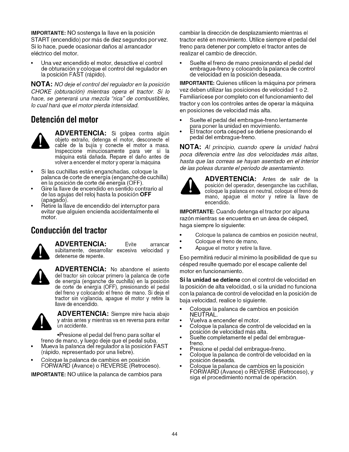
IMPORTANTE: NO sostenga la Ilave en la posici6n
START (encendido) por ma.s de diez segundos por vez.
Si Io hace, puede ocasionar daSos al arrancador
electrico del motor.
• Una vez encendido el motor, desactive el control
de obturaci6n y coloque el control del regulador en
la posici6n FAST (ra.pido).
NOTA: NO deje el control del regulador en la posicidn
CHOKE (obturacidn) mientras opera el tractor. Si Io
hace, se generara una mezcla "rica" de combustibles,
Io cual hara que el motor pierda intensidad.
Detenci6ndelmotor
ADVERTENClA: Si golpea contra algQn
objeto extraSo, detenga el motor, desconecte el
cable de la bujia y conecte el motor a masa.
Inspeccione minuciosamente para ver si la
m_tquina esterdaSada. Repare el daSo antes de
volver a encender el motory operar la m_tquina
• Si las cuchillas esta.n enganchadas, coloque la
palanca de corte de energia (enganche de cuchilla)
en la posici6n de corte de energia (OFF).
• Gire la Ilave de encendido en sentido contrario al
de las agujas del reloj hasta la posici6n OFF
(apagado).
• Retire la Ilave de encendido del interruptor para
evitar que alguien encienda accidentalmente el
motor.
Conducci6ndeltractor
,_ ADVERTENClA: Evite arrancar
sQbitamente, desarrollar excesiva velocidad y
detenerse de repente.
ADVERTENClA: No abandone el asiento
del tractor sin colocar primero la palanca de corte
de energia (enganche de cuchilla) en la posici6n
de corte de energia (OFF), presionando el pedal
del freno y colocando el freno de mano. Si deja el
tractor sin vigilancia, apague el motor y retire la
Ilave de encendido.
_, ADVERTENClA: Siempre mire hacia abajo
y atr_tsantesy mientras va en reversa para evitar
un accidente.
•Presione el pedal del freno para soltar el
freno de mano, y luego deje que el pedal suba.
• Mueva la palanca del regulador a la posici6n FAST
(ra.pido, representado por una liebre).
• Coloque la palanca de cambios en posici6n
FORWARD (Avance) o REVERSE (Retroceso).
IMPORTANTE: NO utilice la palanca de cambios para
cambiar la direcci6n de desplazamiento mientras el
tractor este en movimiento. Utilice siempre el pedal del
freno para detener por completo el tractor antes de
realizar el cambio de direcci6n.
• Suelte el freno de mano presionando el pedal del
embrague-freno y colocando la palanca de control
de velocidad en la posici6n deseada.
IMPORTANTE: Quienes utilicen la ma.quina por primera
vez deben utilizar las posiciones de velocidad 1 o 2.
Familiaricese por completo con el funcionamiento del
tractor y con los controles antes de operar la ma.quina
en posiciones de velocidad ma.s alta.
• Suelte el pedal del embrague-freno lentamente
para poner la unidad en movimiento.
• El tractor corta cesped se detiene presionando el
pedal del embrague-freno.
NOTA: AI principio, cuando opere la unidad habra
poca diferencia entre las dos velocidades mas altas,
hasta que las correas se hayan asentado en el interior
de las poleas durante el periodo de asentamiento.
_, DVERTENClA: Antes de salir de la
posici6n del operador, desenganche las cuchillas,
coloque la palanca en neutral, coloque el freno de
mano, apague el motor y retire la Ilave de
encendido.
IMPORTANTE: Cuando detenga el tractor por alguna
raz6n mientras se encuentra en un Area de cesped,
haga siempre Io siguiente:
Coloque la palanca de cambios en posici6n neutral,
Coloque el freno de mane,
Apague el motor y retire la Ilave.
Eso permitira, reducir al minimo la posibilidad de que su
cesped resulte quemado por el escape caliente del
motor en funcionamiento.
Si la unidad se detiene con el control de velocidad en
la posici6n de alta velocidad, o si la unidad no funciona
con la palanca de control de velocidad en la posici6n de
baja velocidad, realice Io siguiente.
• Coloque la palanca de cambios en posici6n
NEUTRAL.
• Vuelva a encender el motor.
• Coloque la palanca de control de velocidad en la
posici6n de velocidad ma.salta.
• Suelte completamente el pedal del embrague-
freno.
• Presione el pedal del embrague-freno.
• Coloque la palanca de control de velocidad en la
posici6n deseada.
• Coloque la palanca de cambios en la posici6n
FORWARD (Avance) o REVERSE (Retroceso), y
siga el procedimiento normal de operaci6n.
44
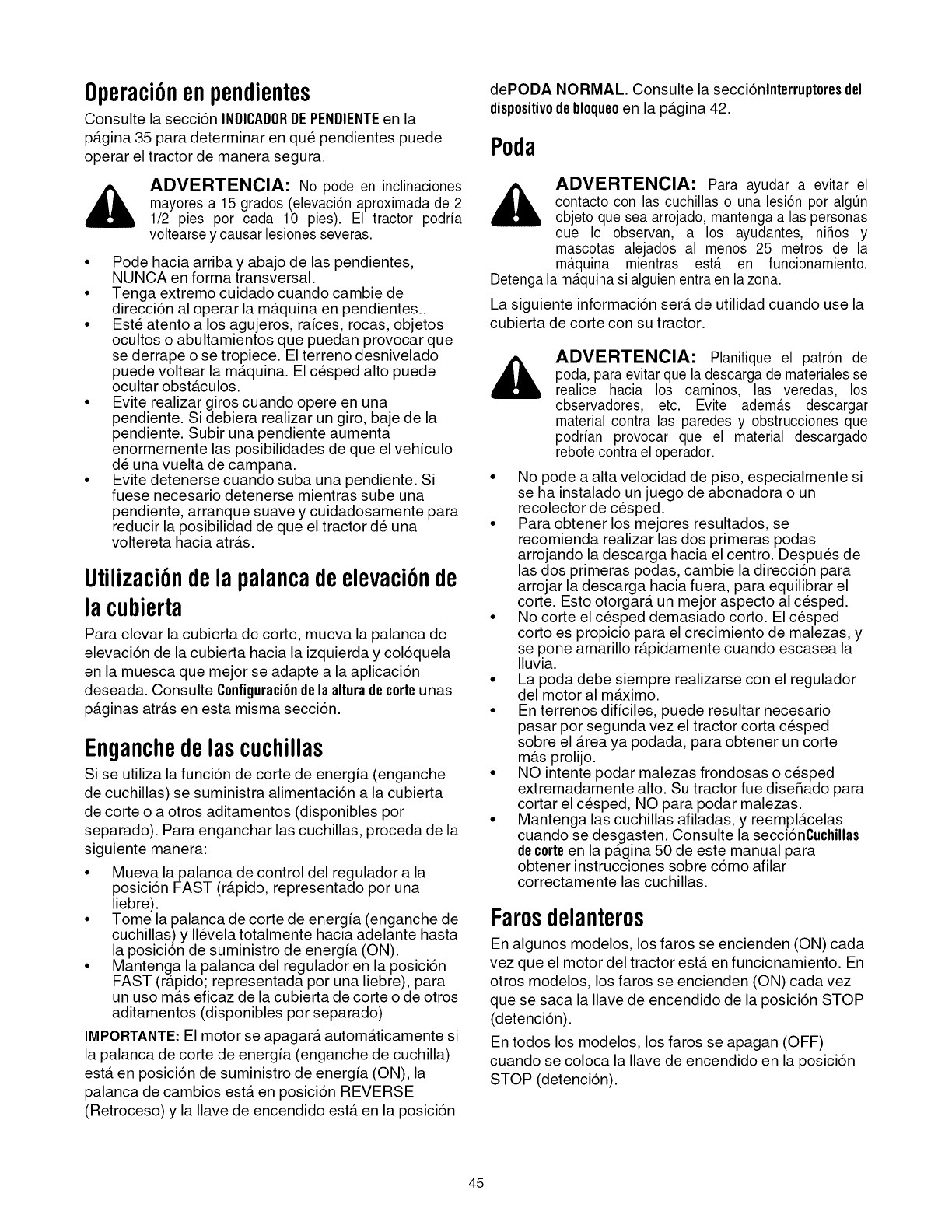
Operaci6nenpendientes
Oonsulte la secci6n INDICADORDEPENDIENTEen la
pAgina 35 para determinar en que pendientes puede
operar el tractor de manera segura.
ADVERTENClA: No pode en inclinaciones
mayores a 15 grados (elevaci6n aproximada de 2
1/2 pies por cada 10 pies). El tractor podria
voltearse y causar lesiones severas.
• Pode hacia arriba y abajo de las pendientes,
NUNCA en forma transversal.
• Tenga extremo cuidado cuando cambie de
direcci6n al operar la mAquina en pendientes..
• Este atento a los agujeros, ra[ces, rocas, objetos
ocultos o abultamientos que puedan provocar que
se derrape o se tropiece. El terreno desnivelado
puede voltear la mAquina. El cesped alto puede
ocultar obstAculos.
• Evite realizar giros cuando opere en una
pendiente. Si debiera realizar un giro, baje de la
pendiente. Subir una pendiente aumenta
enormemente las posibilidades de que el vehiculo
de una vuelta de campana.
• Evite detenerse cuando suba una pendiente. Si
fuese necesario detenerse mientras sube una
pendiente, arranque suave y cuidadosamente para
reducir la posibilidad de que el tractor de una
voltereta hacia atrAs.
Utilizaci6ndela palancadeelevaci6nde
la cubierta
Para elevar la cubierta de code, mueva la palanca de
elevaci6n de la cubierta hacia la izquierda y col6quela
en la muesca que mejor se adapte a la aplicaci6n
deseada. Consulte Configuraci6ndela alturadecorteunas
paginas arras en esta misma secci6n.
Enganchedelas cuchillas
Si se utiliza la funci6n de corte de energ_a (enganche
de cuchillas) se suministra alimentaci6n a la cubierta
de corte o a otros aditamentos (disponibles pot
separado). Para enganchar las cuchillas, proceda de la
siguiente manera:
• Mueva la palanca de control del regulador a la
posici6n FAST (rApido, representado por una
liebre).
• Tome la palanca de corte de energ[a (enganche de
cuchillas) y Ilevela totalmente hacia adelante hasta
la posici6n de suministro de energia (ON).
• Mantenga la palanca del regulador en la posici6n
FAST (rApido; representada por una liebre), para
un uso mAs eficaz de la cubierta de corte o de otros
aditamentos (disponibles por separado)
IMPORTANTE: El motor se apagarA automAticamente si
la palanca de corte de energ[a (enganche de cuchilla)
estA en posici6n de suministro de energia (ON), la
palanca de cambios estA en posici6n REVERSE
(Retroceso) y la Ilave de encendido estA en la posici6n
dePODA NORMAL. Consulte la secci6nlnterruptores del
dispositivodebloqueoen la pagina 42.
Poda
ADVERTENClA: Para ayudar a evitar el
contacto con las cuchillas o una lesi6n por algQn
objeto que sea arrojado, mantenga a las personas
que Io observan, a los ayudantes, niSos y
mascotas alejados al menos 25 metros de la
m_tquina mientras ester en funcionamiento.
Detenga la m_tquinasi alguien entra en la zona.
La siguiente informaci6n serA de utilidad cuando use la
cubierta de corte con su tractor.
ADVERTENClA: Planifique el patr6n de
poda, para evitar que la descarga de materiales se
realice hacia los caminos, las veredas, los
observadores, etc. Evite adem_ts descargar
material contra las paredes y obstrucciones que
podrian provocar que el material descargado
rebote contra el operador.
• No pode a alta velocidad de piso, especialmente si
se ha instalado un juego de abonadora o un
recolector de cesped.
• Para obtener los mejores resultados, se
recomienda realizar las dos primeras podas
arrojando la descarga hacia el centro. Despues de
las dos primeras podas, cambie la direcci6n para
arrojar la descarga hacia fuera, para equilibrar el
code. Esto otorgarA un mejor aspecto al cesped.
• No corte el cesped demasiado corto. El cesped
corto es propicio para el crecimiento de malezas, y
se pone amarillo rApidamente cuando escasea la
Iluvia.
• La poda debe siempre realizarse con el regulador
del motor al maximo.
• En terrenos dificiles, puede resultar necesario
pasar por segunda vez el tractor corta cesped
sobre el Area ya podada, para obtener un corte
mas prolijo.
• NO intente podar malezas frondosas o cesped
extremadamente alto. Su tractor fue diseSado para
cortar el cesped, NO para podar malezas.
• Mantenga las cuchillas afiladas, y reemplacelas
cuando se desgasten. Consulte la secci6nCuchillas
decerte en la pagina 50 de este manual para
obtener instrucciones sobre c6mo afilar
correctamente las cuchillas.
Farosdelanteros
En algunos modelos, los faros se encienden (ON) cada
vez que el motor del tractor esta en funcionamiento. En
otros modelos, los faros se encienden (ON) cada vez
que se saca la Ilave de encendido de la posici6n STOP
(detenci6n).
En todos los modelos, los faros se apagan (OFF)
cuando se coloca la Ilave de encendido en la posici6n
STOP (detenci6n).
45
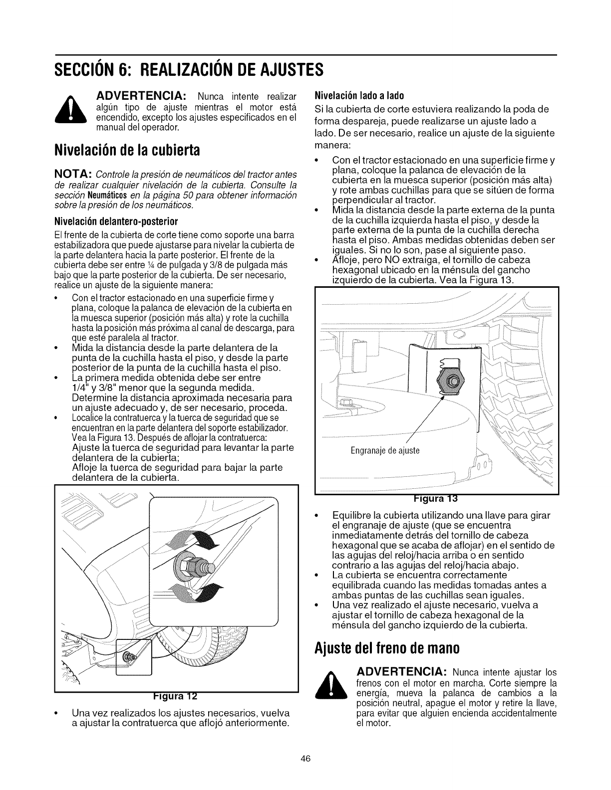
SECCION6: REALIZACIONDEAJUSTES
,i_ ADVERTENClA: Nunca intente realizar
alg_n tipo de ajuste mientras el motor ester
encendido, excepto los ajustes especificados en el
manual del operador.
Nivelaci6ndela cubierta
NOTA: Controle lapresidn de neumaticos del tractor antes
de realizar cualquier nivelacidn de la cubierta. Consulte la
seccidn Neum_tic0sen la pagina 50 para obtener informacidn
sobre lapresidn de los neumaticos.
Nivelaci6n delantero-posterior
El frente de lacubierta de corte tiene como soporte una barra
estabilizadora que puede ajustarse para nivelar la cubierta de
la parte delantera hacia la parte posterior. Elfrente de la
cubierta debe ser entre 1Ade pulgada y 3/8 de pulgada m_ts
bajo que la parte posterior de la cubierta. De ser necesario,
realice un ajuste de la siguiente manera:
• Con el tractor estacionado en una superficie firme y
plana, coloque la palanca de elevaci6n de la cubierta en
la muesca superior (posici6n m_tsalta) y rote la cuchilla
hasta laposici6n m_tspr6xima alcanal dedescarga, para
que est_ paralela al tractor.
• Mida la distancia desde la parte delantera de la
punta de la cuchilla hasta el piso, y desde la parte
posterior de la punta de la cuchilla hasta el piso.
• La primera medida obtenida debe ser entre
1/4" y 3/8" menor que la segunda medida.
Determine la distancia aproximada necesaria para
un ajuste adecuado y, de ser necesario, proceda.
• Localicelacontratuercay latuercade seguridadquese
encuentranenla partedelanteradelsoporteestabilizador.
Vea la Figura13. Despuesdeaflojarla contratuerca:
Ajuste la tuerca de seguridad para levantar la parte
delantera de la cubierta;
Afloje la tuerca de seguridad para bajar la parte
delantera de la cubierta.
Nivelaci6n lade alade
Si la cubierta de corte estuviera realizando la poda de
forma despareja, puede realizarse un ajuste lado a
lado. De ser necesario, realice un ajuste de la siguiente
manera:
• Con el tractor estacionado en una superficie firme y
plana, coloque la palanca de elevaci6n de la
cubierta en la muesca superior (posici6n ma.s alta)
y rote ambas cuchillas para que se situen de forma
perpendicular al tractor.
• Mida la distancia desde la parte externa de la punta
de la cuchilla izquierda hasta el piso, y desde la
parte externa de la punta de la cuchilla derecha
hasta el piso. Ambas medidas obtenidas deben ser
iguales. Si no Io son, pase al siguiente paso.
• Afloje, pero NO extraiga, el tornillo de cabeza
hexagonal ubicado en la mensula del gancho
izquierdo de la cubierta. Vea la Figura 13.
/
Ilgura 12
Una vez realizados los ajustes necesarios, vuelva
a ajustar la contratuerca que afloj6 anteriormente.
P,gura 13
• Equilibre la cubierta utilizando una Ilave para girar
el engranaje de ajuste (que se encuentra
inmediatamente detra.s del tornillo de cabeza
hexagonal que se acaba de aflojar) en el sentido de
las agujas del reloj/hacia arriba o en sentido
contrario alas agujas del reloj/hacia abajo.
• La cubierta se encuentra correctamente
equilibrada cuando las medidas tomadas antes a
ambas puntas de las cuchillas sean iguales.
• Una vez realizado el ajuste necesario, vuelva a
ajustar el tornillo de cabeza hexagonal de la
mensula del gancho izquierdo de la cubierta.
Ajustedelfrenodemano
,_ ADVERTENCIA: Nunca intente ajustar los
frenos con el motor en marcha. Corte siempre la
energia, mueva la palanca de cambios a la
posici6n neutral, apague el motor y retire la Ilave,
para evitar que alguien encienda accidentalmente
el motor.
46
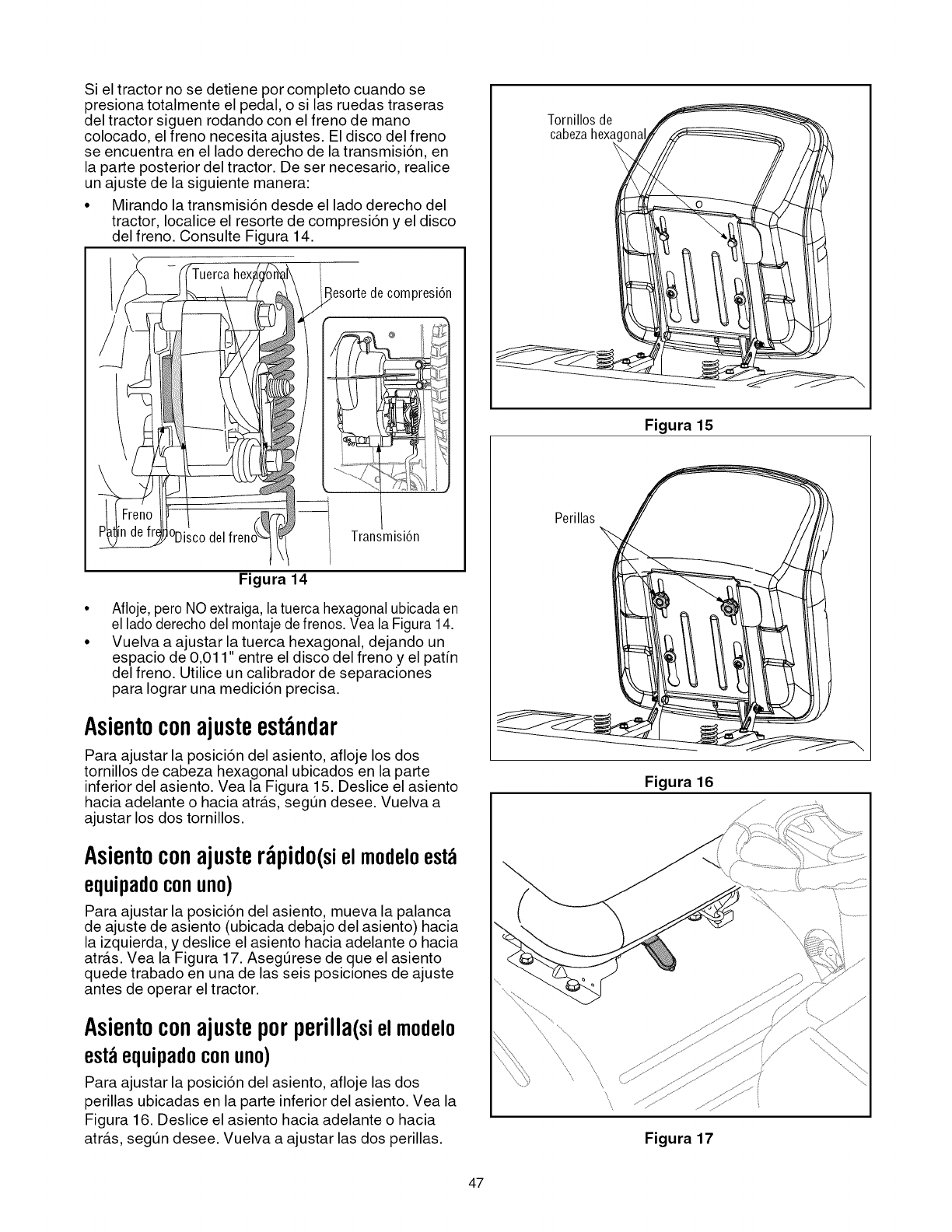
Si el tractor no se detiene por completo cuando se
presiona totalmente el pedal, o si las ruedas traseras
del tractor siguen rodando con el freno de mano
colocado, el freno necesita ajustes. El disco del freno
se encuentra en el lado derecho de la transmisi6n, en
la parte posterior del tractor. De set necesario, realice
un ajuste de la siguiente manera:
• Mirando la transmisi6n desde el lado derecho del
tractor, Iocalice el resorte de compresi6n y el disco
del freno. Consulte Figura 14.
Bes0rtedec0mpresi6n
@
°Disc0 del Transmisi6n
Figura 14
Afloje, pero NO extraiga, la tuerca hexagonal ubicada en
el lado derecho del montaje defrenos. Vea la Figura 14.
Vuelva a ajustar la tuerca hexagonal, dejando un
espacio de 0,011" entre el disco del freno y el pafin
del freno. Utilice un calibrador de separaciones
para Iograr una medici6n precisa.
Asientoconajusteest_ndar
Para ajustar la posici6n del asiento, afloje los dos
tornillos de cabeza hexagonal ubicados en la parte
inferior del asiento. Vea la Figura 15. Deslice el asiento
hacia adelante o hacia atra.s, segt_n desee. Vuelva a
ajustar los dos tornillos.
Asientoconajuster_pido(sielmodeloest_
equipadoconuno)
Para ajustar la posici6n del asiento, mueva la palanca
de ajuste de asiento (ubicada debajo del asiento) hacia
la izquierda, y deslice el asiento hacia adelante o hacia
atra.s. Vea la Figura 17. Asegt_rese de que el asiento
quede trabado en una de las seis posiciones de ajuste
antes de operar el tractor.
Asientoconajusteporperilla(sielmodelo
est_equipadoconuno)
Para ajustar la posici6n del asiento, afloje las dos
perillas ubicadas en la parte inferior del asiento. Vea la
Figura 16. Deslice el asiento hacia adelante o hacia
atra.s, segt_n desee. Vuelva a ajustar las dos perillas.
\
T0rnill0s de
cabezahexac
Figura 15
Perillas
Figura 16
\
Figura 17
47
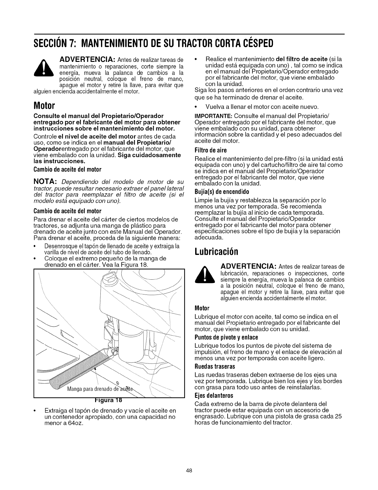
SECCION7: MANTENIMIENTODESUTRACTORCORTAClaSPED
,_ ADVERTENClA: Antes de realizar tareas de
mantenimiento o reparaciones, corte siempre la
energia, mueva la palanca de cambios a la
posici6n neutral, coloque el freno de mano,
apague el motor y retire la Ilave, para evitar que
alguien encienda accidentalmente el motor.
Motor
Consulte el manual del Propietario/Operador
entregado por el fabricante del motor para obtener
instrucciones sobre el mantenimiento del motor.
Controle el nivel de aceite del motor antes de cada
uso, como se indica en el manual del Propietario/
Operadorentregado por el fabricante del motor, que
viene embalado con la unidad. Siga cuidadosamente
las instrucciones.
Cambio de aceite delmotor
NOTA: Dependiendo del modelo de motor de su
tractor, puede resultar necesario extraer el panel lateral
del tractor para reemplazar el filtro de aceite (si el
modelo esta equipado con uno).
Cambio de aceite delmotor
Para drenar el aceite del ca.rter de ciertos modelos de
tractores, se adjunta una manga de pla.stico para
drenado de aceite junto con este Manual del Operador.
Para drenar el aceite, proceda de la siguiente manera:
° Desenrosque el tap6n de Ilenadode aceite y extraiga la
varilla de nivel de aceite del tubo de Ilenado.
• Coloque el extremo pequeSo de la manga de
drenado en el ca.rter. Vea la Figura 18.
Manga
• Extraiga el tap6n de drenado y vacie el aceite en
un contenedor apropiado, con una capacidad no
menor a 64oz.
• Realice el mantenimiento del filtro de aceite (si la
unidad esta. equipada con uno), tal como se indica
en el manual del Propietario/Operador entregado
por el fabricante del motor, que viene embalado
con la unidad.
Siga los pasos anteriores en el orden contrario una vez
que se ha terminado de drenar el aceite.
• Vuelva a Ilenar el motor con aceite nuevo.
IMPORTANTE: Consulte el manual del Propietario/
Operador entregado por el fabricante del motor, que
viene embalado con su unidad, para obtener
informaci6n sobre la cantidad y el peso adecuados del
aceite del motor.
Filtro de aire
Realice el mantenimiento del pre-filtro (si la unidad esta.
equipada con uno) y del cartucho/filtro de aire tal como
se indica en el manual del Propietario/Operador
entregado por el fabricante del motor, que viene
embalado con la unidad.
Bujia(s)de encendido
Limpie la bujia y restablezca la separaci6n por Io
menos una vez por temporada. Se recomienda
reemplazar la bujia al inicio de cada temporada.
Consulte el manual del Propietario/Operador
entregado por el fabricante del motor para obtener
especificaciones sobre el tipo de buj_a y la separaci6n
adecuada.
Lubricaci6n
ADVERTENCIA: Antes de realizar tareas de
lubricaci6n, reparaciones o inspecciones, corte
siempre la energia, mueva la palanca de cambios
a la posici6n neutral, coloque el freno de mano,
apague el motor y retire la Ilave, para evitar que
alguien encienda accidentalmente el motor.
Motor
Lubrique el motor con aceite, tal como se indica en el
manual del Propietario entregado por el fabricante del
motor, que viene embalado con su unidad.
Puntosde pivotey enlace
Lubrique todos los puntos de pivote del sistema de
impulsi6n, el freno de mano y el enlace de elevaci6n al
menos una vez por temporada con aceite ligero.
Ruedastraseras
Las ruedas traseras deben extraerse de los ejes una
vez por temporada. Lubrique bien los ejes y los bordes
con grasa para todo uso antes de reinstalarlas.
Ejes delanter0s
Cada extremo de la barra de pivote delantera del
tractor puede estar equipada con un accesorio de
engrasado. Lubrique con una pistola de grasa cada 25
horas de funcionamiento del tractor.
48
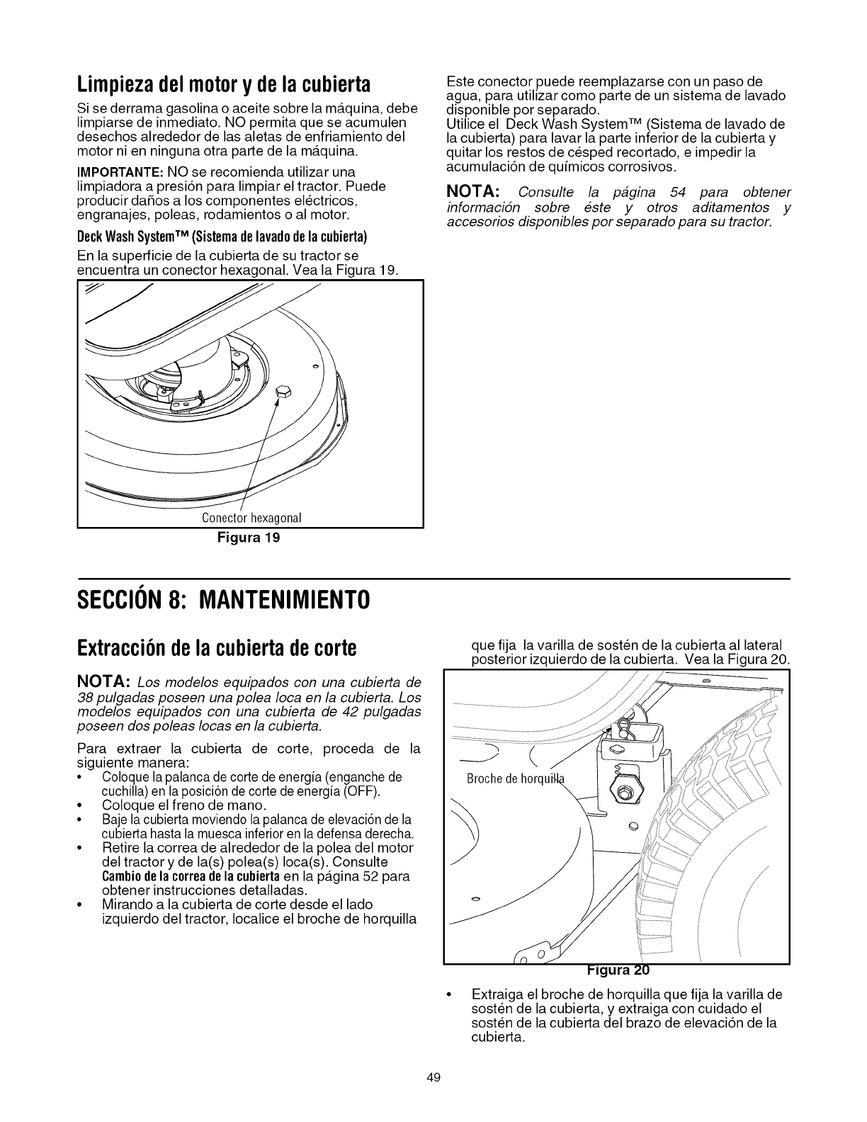
Limpiezadelmotorydelacubierta
Si se derrama gasolina o aceite sobre la ma.quina, debe
limpiarse de inmediato. NO permita que se acumulen
desechos alrededor de las aletas de enfriamiento del
motor ni en ninguna otra parte de la ma.quina.
IMPORTANTE: NO se recomienda utilizar una
limpiadora a presi6n para limpiar el tractor. Puede
producir daSos a los componentes electricos,
engranajes, poleas, rodamientos o al motor.
DeckWashSystemTM (Sistemadelavadodela cubierta)
En la superficie de la cubierta de su tractor se
encuentra un conector hexagonal. Vea la Figura 19.
Este conector puede reemplazarse con un paso de
agua, para utilizar como parte de un sistema de lavado
disponible por separado.
Utilice el Deck Wash System TM (Sistema de lavado de
la cubierta) para lavar la parte inferior de la cubierta y
quitar los restos de cesped recortado, e impedir la
acumulaci6n de quimicos corrosivos.
NOTA: Consulte la pagina 54 para obtener
informaciSn sobre este y otros aditamentos y
accesorios disponibles por separado para su tractor.
Conectorhexagonal
Figura 19
SECCION8: MANTENIMIENTO
Extracci6ndela cubiertadecorte
NOTA: Los modelos equipados con una cubierta de
38 pulgadas poseen una polea Ioca en la cubierta. Los
modelos equipados con una cubierta de 42 pulgadas
poseen dos poleas Iocas en la cubierta.
Para extraer la cubierta de code, proceda de la
siguiente manera:
• Coloque lapalanca de corte de energia (enganche de
cuchilla) en la posici6n de corte de energia (OFF).
• Coloque el freno de mano.
• Baje la cubierta moviendo la palanca de elevaci6n de la
cubierta hasta la muesca inferior en la defensa derecha.
• Retire la correa de alrededor de la polea del motor
del tractor y de la(s) polea(s) Ioca(s). Consulte
Cambi0dela c0rreadela cubiertaen la pa.gina 52 para
obtener instrucciones detalladas.
• Mirando a la cubierta de corte desde el lado
izquierdo del tractor, Iocalice el broche de horquilla
que fija la varilla de sosten de la cubierta al lateral
posterior izquierdo de la cubierta. Vea la Figura 20.
//
J
/
/
i!
PJgura 20
Extraiga el broche de horquilla que fija la varilla de
sosten de la cubierta, y extraiga con cuidado el
sosten de la cubierta del brazo de elevaci6n de la
cubierta.
49
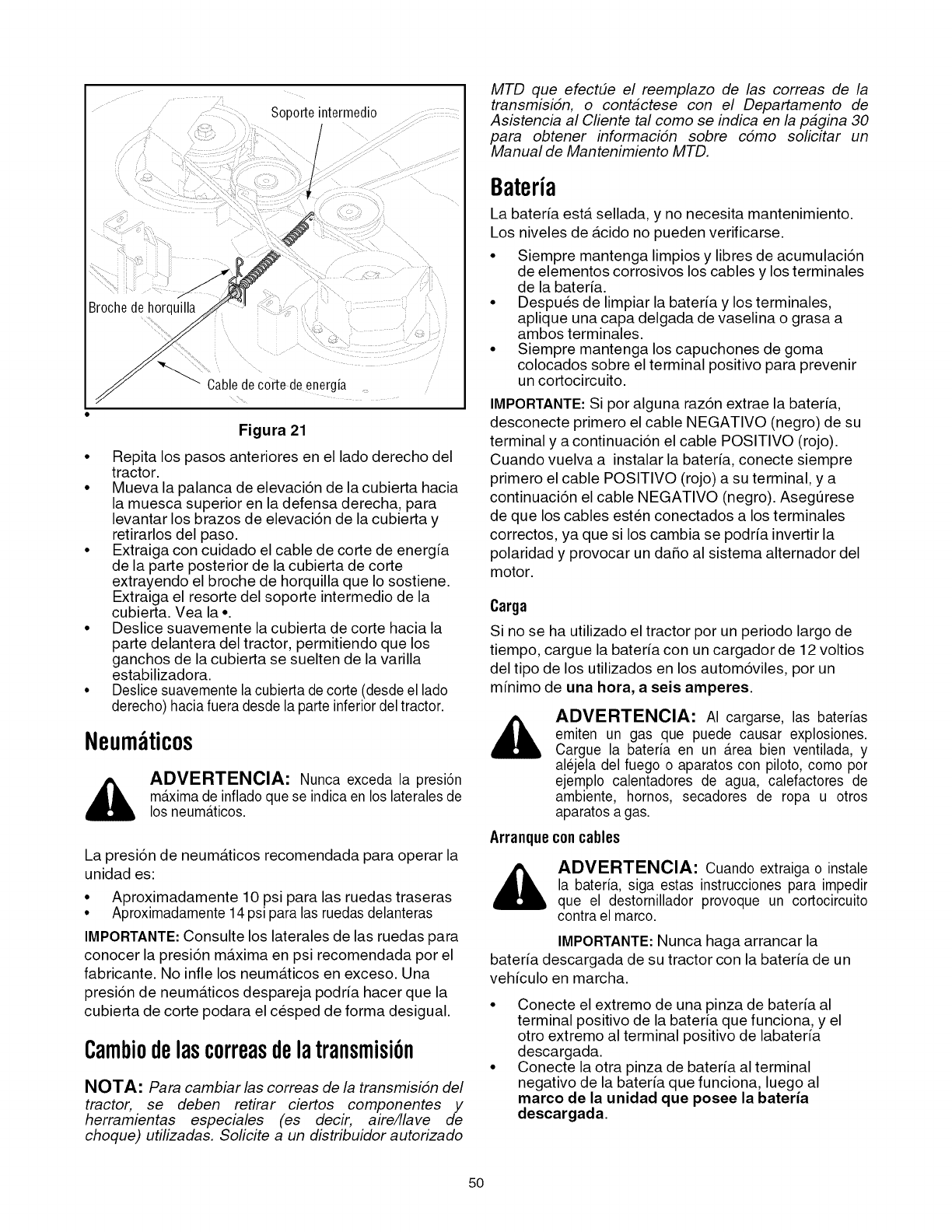
Soporteintermedio
/
/
Broche de horquilla
Cabledecorte de energia
Figura 21
• Repita los pasos anteriores en el lado derecho del
tractor.
• Mueva la palanca de elevaci6n de la cubierta hacia
la muesca superior en la defensa derecha, para
levantar los brazos de elevaci6n de la cubierta y
retirarlos del paso.
• Extraiga con cuidado el cable de corte de energia
de la parte posterior de la cubierta de corte
extrayendo el broche de horquilla que Io sostiene.
Extraiga el resorte del soporte intermedio de la
cubierta. Vea la •
• Deslice suavemente la cubierta de corte hacia la
parte delantera del tractor, permitiendo que los
ganchos de la cubierta se suelten de la varilla
estabilizadora.
• Deslice suavemente lacubierta de corte (desde el lado
derecho) hacia fuera desde la parte inferior del tractor.
Neum ticos
ADVERTENCIA: Nunca exceda la presi6n
maxima de inflado que se indica en los laterales de
los neum_tticos.
La presi6n de neuma.ticos recomendada para operar la
unidad es:
• Aproximadamente 10 psi para las ruedas traseras
• Aproximadamente 14 psi para las ruedas delanteras
IMPORTANTE: Consulte los laterales de las ruedas para
conocer la presi6n maxima en psi recomendada por el
fabricante. No infle los neuma.ticos en exceso. Una
presi6n de neuma.ticos despareja podria hacer que la
cubierta de corte podara el cesped de forma desigual.
Cambiodelascorreasdelatransmisi6n
NOTA: Para cambiar las correas de la transmisiSn del
tractor, se deben retirar ciertos componentes y
herramientas especiales (es decir, aire/llave de
choque) utilizadas. Solicite a un distribuidor autorizado
MTD que efectEle el reemplazo de las correas de la
transmisiSn, o contactese con el Departamento de
Asistencia al Cliente tal como se indica en la pagina 30
para obtener informaciSn sobre cSmo solicitar un
Manual de Mantenimiento MTD.
Bateria
La bateria esta. sellada, y no necesita mantenimiento.
Los niveles de a.cido no pueden verificarse.
• Siempre mantenga limpios y libres de acumulaci6n
de elementos corrosivos los cables y los terminales
de la bateria.
• Despues de limpiar la bater[a y los terminales,
aplique una capa delgada de vaselina o grasa a
ambos terminales.
• Siempre mantenga los capuchones de goma
colocados sobre el terminal positivo para prevenir
un cortocircuito.
IMPORTANTE:Si por alguna raz6n extrae la bater[a,
desconecte primero el cable NEGATIVO (negro) de su
terminal y a continuaci6n el cable POSITIVO (rojo).
Cuando vuelva a instalar la bater[a, conecte siempre
primero el cable POSITIVO (rojo) a su terminal, y a
continuaci6n el cable NEGATIVO (negro). Asegurese
de que los cables esten conectados a los terminales
correctos, ya que si los cambia se podr[a invertir la
polaridad y provocar un daSo al sistema alternador del
motor.
Carga
Si no se ha utilizado el tractor por un periodo largo de
tiempo, cargue la bateria con un cargador de 12 voltios
del tipo de los utilizados en los autom6viles, por un
minimo de una hora, a seis amperes.
Arranque
&
ADVERTENClA: AI cargarse, las baterias
emiten un gas que puede causar explosiones.
Cargue la bateria en un Area bien ventilada, y
alejela del fuego o aparatos con piloto, como por
ejemplo calentadores de agua, calefactores de
ambiente, hornos, secadores de ropa u otros
aparatos a gas.
concables
ADVERTENClA: Cuando extraiga o instale
la bateria, siga estas instrucciones para impedir
que el destornillador provoque un cortocircuito
contra el marco.
IMPORTANTE: Nunca haga arrancar la
bateria descargada de su tractor con la bateria de un
vehiculo en marcha.
• Conecte el extremo de una pinza de bateria al
terminal positivo de la bateria que funciona, y el
otto extremo al terminal positivo de labateria
descargada.
• Conecte la otra pinza de bater[a al terminal
negativo de la bateria que funciona, luego al
marco de la unidad que posee la bateria
descargada.
50
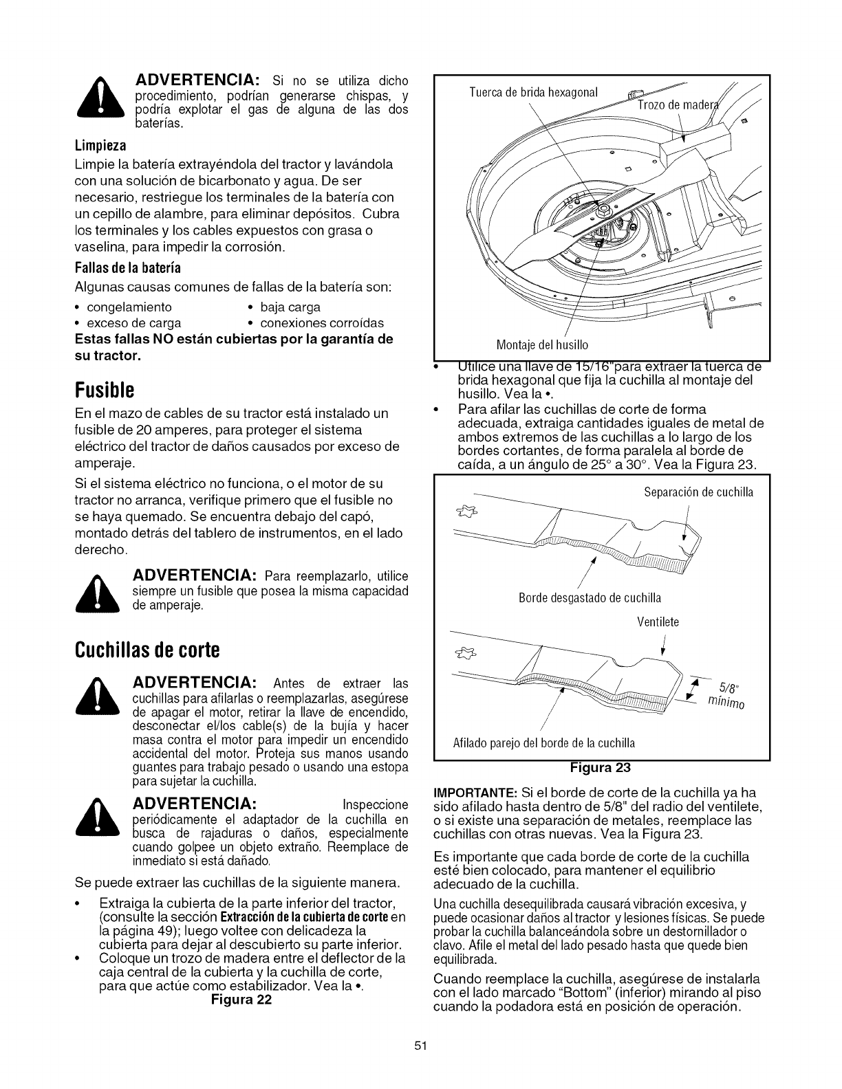
_ ADVERTENClA: Si no se utiliza dicho
procedimiento, podrian generarse chispas, y
podria explotar el gas de alguna de las dos
baterias.
Limpieza
Limpie la bater_a extrayendola del tractor y lava.ndola
con una soluci6n de bicarbonato y agua. De ser
necesario, restriegue los terminales de la bateria con
un cepillo de alambre, para eliminar dep6sitos. Cubra
los terminales y los cables expuestos con grasa o
vaselina, para impedir la corrosi6n.
Fallas de la bateria
Algunas causas comunes de fallas de la bater_a son:
• congelamiento • baja carga
•exceso de carga • conexiones corroidas
Estas fallas NO est_n cubiertas por la garantJa de
su tractor.
Fusible
En el mazo de cables de su tractor esta instalado un
fusible de 20 amperes, para proteger el sistema
electrico del tractor de daSos causados por exceso de
amperaje.
Si el sistema electrico no funciona, o el motor de su
tractor no arranca, verifique primero que el fusible no
se haya quemado. Se encuentra debajo del cap6,
montado detras del tablero de instrumentos, en el lado
derecho.
ADVERTENClA: Para reemplazarlo, utilice
siempre un fusible que posea la misma capacidad
de amperaje.
Cuchillasdecorte
ADVERTENClA: Antes de extraer las
cuchillas para afilarlas o reemplazarlas, asegQrese
de apagar el motor, retirar la Ilave de encendido,
desconectar el/los cable(s) de la bujia y hacer
masa contra el motor para impedir un encendido
accidental del motor. Proteja sus manos usando
guantes para trabajo pesado o usando una estopa
para sujetar la cuchilla.
ADVERTENClA: Inspeccione
peri6dicamente el adaptador de la cuchilla en
busca de rajaduras o daSos, especialmente
cuando golpee un objeto extraSo. Reemplace de
inmediato si esterdaSado.
Se puede extraer las cuchillas de la siguiente manera.
• Extraiga la cubierta de la parte inferior del tractor,
(consulte la secci6n Extracci6ndela cubiertadecerteen
la pagina 49); luego voltee con delicadeza la
cubierta para dejar al descubierto su parte inferior.
• Coloque un trozo de madera entre el deflector de la
caja central de la cubierta y la cuchilla de code,
para que actue como estabilizador. Vea la •
Figura 22
Tuercade brida hexagonal
Montaje del husillo
Ut_l_ceuna Ilave de 1b/16"para extraer la tuerca de
brida hexagonal que fija la cuchilla al montaje del
husillo. Vea la •
Para afilar las cuchillas de corte de forma
adecuada, extraiga cantidades iguales de metal de
ambos extremos de las cuchillas a Io largo de los
bordes cortantes, de forma paralela al borde de
ca[da, a un angulo de 25° a 30°. Vea la Figura 23.
Separaci6n decuchilla
/
Bordedesgastadodecuchilla
Ventilete
Nilado parejo del borde de la cuchilla
Figura 23
IMPORTANTE: Si el borde de corte de la cuchilla ya ha
sido afilado hasta dentro de 5/8" del radio del ventilete,
o si existe una separaci6n de metales, reemplace las
cuchillas con otras nuevas. Vea la Figura 23.
Es importante que cada borde de corte de la cuchilla
este bien colocado, para mantener el equilibrio
adecuado de la cuchilla.
Una cuchilla desequilibrada causar_tvibraci6n excesiva, y
puede ocasionardaSos altractor y lesionesfisicas. Se puede
probar la cuchilla balance_tndolasobre un destornillador o
clavo. Afile el metal del lado pesado hasta que quede bien
equilibrada.
Cuando reemplace la cuchilla, asegurese de instalarla
con el lado marcado "Bottom" (inferior) mirando al piso
cuando la podadora esta. en posici6n de operaci6n.
51
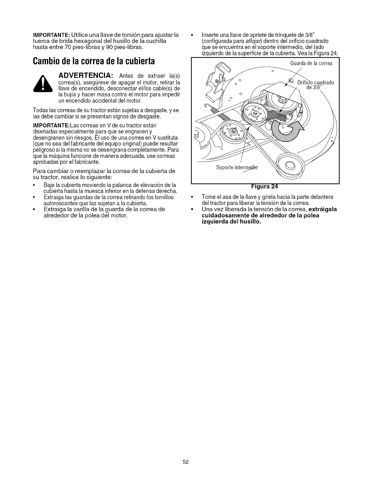
IMPORTANTE: Utilice una Ilave de torsi6n para ajustar la
tuerca de brida hexagonal del husillo de la cuchilla
hasta entre 70 pies-libras y 90 pies-libras.
Cambiodelacorreadela cubierta
,_ ADVERTENClA: Antes de extraer la(s)
correa(s), aseg_rese de apagar el motor, retirar la
Ilave de encendido, desconectar el/los cable(s) de
la bujia y hacer masa contra el motor para impedir
un encendido accidental del motor.
Todas las correas de su tractor estansujetas a desgaste,y se
las debe cambiar si se presentan signos de desgaste.
IMPORTANTE:Las correas en V de su tractor esta.n
diseffadas especialmente para que se engranen y
desengranen sin riesgos. El uso de unacorrea en V sustituta
(que no sea delfabricante del equipo original) puede resultar
peligroso si la misma nose desengrana completamente. Para
que la ma.quinafuncione de manera adecuada, use correas
aprobadas por elfabricante.
Para cambiar o reemplazar la correa de la cubierta de
su tractor, realice Io siguiente:
• Baje la cubierta moviendo la palanca de elevaci6n de la
cubierta hasta la muesca inferior en la defensa derecha.
• Extraiga las guardas de lacorrea retirando los tornillos
autoroscantes que las sujetan a la cubierta.
• Extraiga la varilla de la guarda de la correa de
alrededor de la polea del motor.
Inserte una Ilave de apriete de trinquete de 3/8"
(configuradapara aflojaf) dentro del orificio cuadrado
que se encuentra en el soporte intermedio, del lado
izquierdo de la superficie de lacubierta. Vea la Figura 24.
Guardade la correa
Soporte inte_
Figura 24
Tome el asa de la Ilavey girela hacia la parte delantera
del tractor para liberar la tensi6n de lacorrea.
Una vez liberada la tensi6n de la correa, extr_igala
cuidadosamente de alrededor de la polea
izquierda del husillo.
52
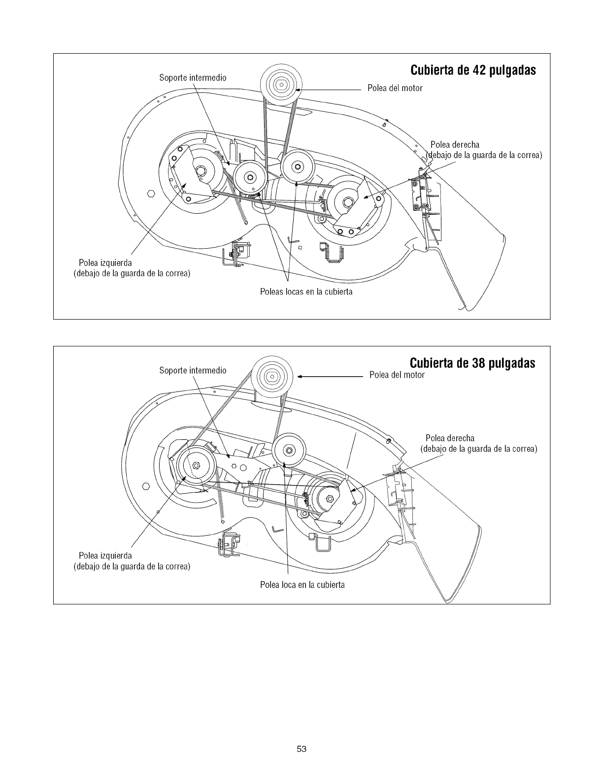
Soporteintermedio Cubiertade42 pulgadas
Poleadel motor
Poleaderecha
ebajo de la guardade la correa)
©
Poleaizquierda
(debajodelaguardadelacorrea)
Poleas Iocasen la cubierta
Soporte intermedio Cubiertade 38 pulgadas
Poleadel motor
/Poleaderecha
(debajo de la guardade la correa)
Poleaizquierda
(debajodelaguardadelacorrea)
Polea Iocaen la cubierta
53
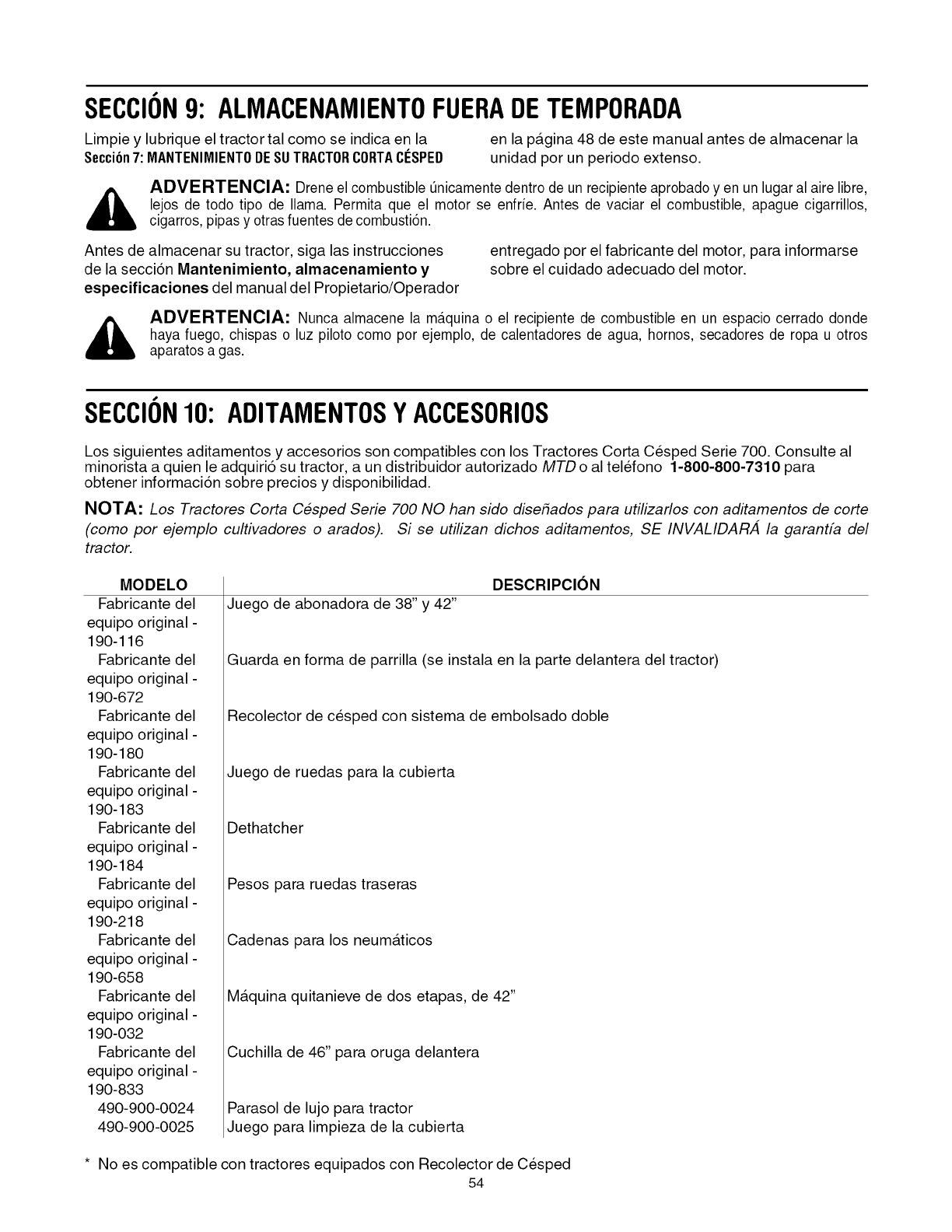
SECCION9: ALMACENAMIENTOFUERADETEMPORADA
Limpie y lubrique el tractor tal como se indica en la
SecciCn7:MANTENIMIENTODESUTRACTORCORTAClaSPED en la pa.gina 48 de este manual antes de almacenar la
unidad por un periodo extenso.
ADVERTENClA: Drene el combustible Qnicamentedentro de un recipiente aprobadoyen un lugar al aire libre,
lejos de todo tipo de llama. Permita que el motor se enfrie. Antes de vaciar el combustible, apague cigarrillos,
cigarros, pipas y otrasfuentes de combusti6n.
Antes de almacenar su tractor, siga las instrucciones
de la secci6n Mantenimiento, almacenamiento y
especificaciones del manual del Propietario/Operador
entregado por el fabricante del motor, para informarse
sobre el cuidado adecuado del motor.
,i_ ADVERTENClA: Nunca almacene la m_tquinao el recipiente de combustible en un espacio cerrado donde
haya fuego, chispas o luz piloto como por ejemplo, de calentadores de agua, hornos, secadores de ropa u otros
aparatos a gas.
SECCION10: ADITAMENTOSYACCESORIOS
Los siguientes aditamentos y accesorios son compatibles con los Tractores Corta Cesped Serie 700. Consulte al
minorista a quien le adquiri6 su tractor, a un distribuidor autorizado MTD o al telefono 1-800-800-7310 para
obtener informaci6n sobre precios y disponibilidad.
NOTA: Los Tractores Corta Cesped Serie 700 NO han sido disehados para utilizarlos con aditamentos de corte
(como por ejemplo cultivadores o arados). Si se utilizan dichos aditamentos, SE INVALIDARA la garantfa del
tractor.
MODELO
Fabricante del
equipo original -
190-116
Fabricante del
equlpo original -
190-672
Fabricante del
equlpo original -
190-180
Fabricante del
equlpo original -
190-183
Fabricante del
equlpo original -
190-184
Fabricante del
equlpo original -
190-218
Fabricante del
equlpo original -
190-658
Fabricante del
equlpo original -
190-032
Fabricante del
equlpo original -
190-833
490-900-0024
490-900-0025
Juego de abonadora de 38" y 42"
DESCRIPClON
Guarda en forma de parrilla (se instala en la parte delantera del tractor)
Recolector de cesped con sistema de embolsado doble
Juego de ruedas para la cubierta
Dethatcher
Pesos para ruedas traseras
Cadenas para los neuma.ticos
Ma.quina quitanieve de dos etapas, de 42"
Cuchilla de 46" para oruga delantera
Parasol de lujo para tractor
Juego para limpieza de la cubierta
* No es compatible con tractores equipados con Recolector de Cesped
54
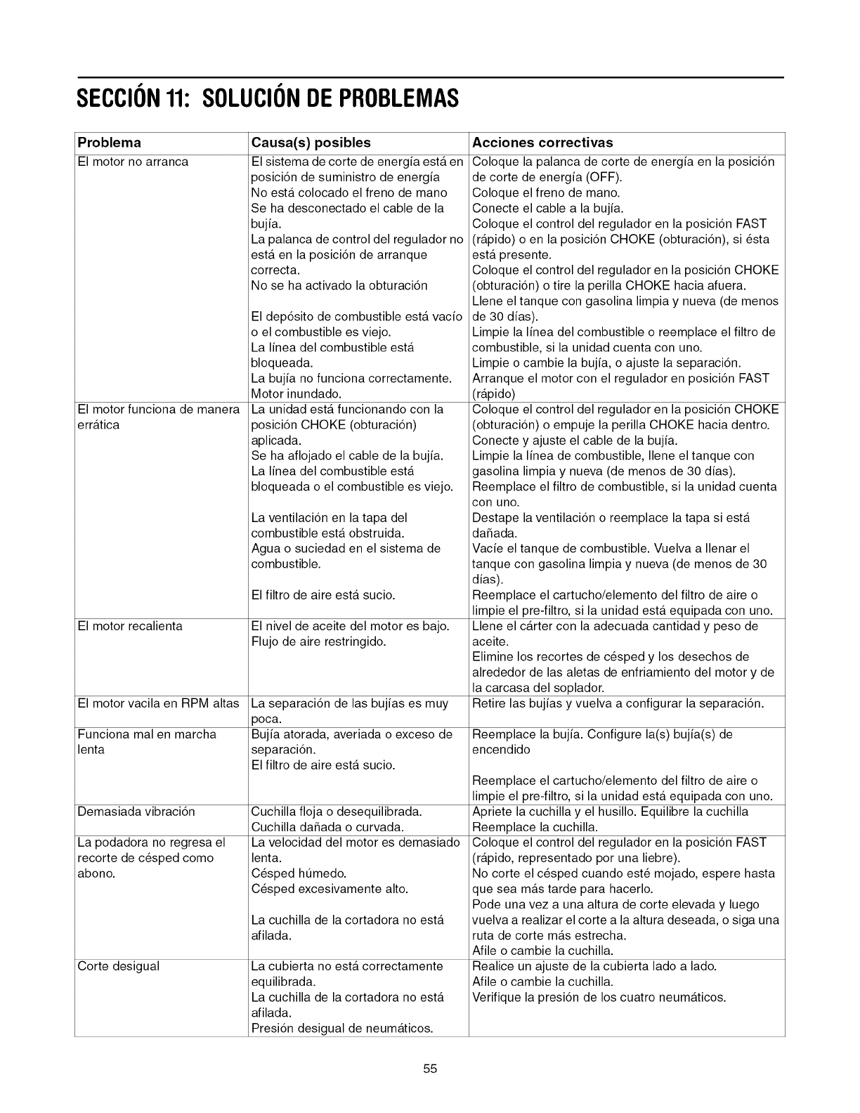
SECCION11: SOLUCIONDEPROBLEMAS
Problema
El motor no arranca
El motor funciona de manera
erratica
El motor recalienta
El motor vacila en RPM altas
Funciona mal en marcha
lenta
Demasiada vibraci6n
La podadora no regresa el
recorte de c_sped como
abono.
Corte desigual
Causa(s) posibles
El sistema de corte de energia esta en
posici6n de suministro de energia
No esta colocado el freno de mano
Se ha desconectado el cable de la
bujia.
La palanca de control del regulador no
esta en la posici6n de arranque
correcta.
No se ha activado la obturaci6n
El dep6sito de combustible esta vacio
o el combustible es viejo.
La linea del combustible esta
bloqueada.
La bujia no funciona correctamente.
Motor inundado.
La unidad esta funcionando con la
posici6n CHOKE (obturaci6n)
aplicada.
Se ha aflojado el cable de la bujia.
La linea del combustible esta
bloqueada o el combustible es viejo.
La ventilaci6n en la tapa del
combustible esta obstruida.
Agua o suciedad en el sistema de
combustible.
El filtro de aire esta sucio.
El nivel de aceite del motor es bajo.
Flujo de aire restringido.
La separaci6n de las bujias es muy
poca.
Bujia atorada, averiada o exceso de
separaci6n.
El filtro de aire esta sucio.
Cuchilla floja o desequilibrada.
Cuchilla daSada o curvada.
La velocidad del motor es demasiado
lenta.
C6sped ht]medo.
C_sped excesivamente alto.
La cuchilla de la cortadora no esta
afilada.
La cubierta no esta correctamente
equilibrada.
La cuchilla de la cortadora no esta
afilada.
Presi6n desigual de neumaticos.
Acciones correctivas
Coloque la palanca de corte de energia en la posici6n
de corte de energia (OFF).
Coloque el freno de mano.
Conecte el cable a la bujia.
Coloque el control del regulador en la posici6n FAST
(rapido) o en la posici6n CHOKE (obturaci6n), si _sta
esta presente.
Coloque el control del regulador en la posici6n CHOKE
(obturaci6n) o tire la perilla CHOKE hacia afuera.
Llene el tanque con gasolina limpia y nueva (de menos
de 30 dias).
Limpie la linea del combustible o reemplace el filtro de
combustible, si la unidad cuenta con uno.
Limpie o cambie la bujia, o ajuste la separaci6n.
Arranque el motor con el regulador en posici6n FAST
(rapido)
Coloque el control del regulador en la posici6n CHOKE
(obturaci6n) o empuje la perilla CHOKE hacia dentro.
Conecte y ajuste el cable de la bujia.
Limpie la linea de combustible, Ilene el tanque con
gasolina limpia y nueva (de menos de 30 dias).
Reemplace el filtro de combustible, si la unidad cuenta
con uno.
Destape la ventilaci6n o reemplace la tapa siesta
da_ada.
Vacfe el tanque de combustible. Vuelva a Ilenar el
tanque con gasolina limpia y nueva (de menos de 30
dias).
Reemplace el cartucho/elemento del filtro de aire o
limpie el pre-filtro, si la unidad esta equipada con uno.
Llene el carter con la adecuada cantidad y peso de
aceite.
Elimine los recortes de c_sped y los desechos de
alrededor de las aletas de enfriamiento del motor y de
la carcasa del soplador.
Retire las bujias y vuelva a configurar la separaci6n.
Reemplace la bujia. Configure la(s) bujia(s) de
encendido
Reemplace el cartucho/elemento del filtro de aire o
limpie el pre-filtro, si la unidad esta equipada con uno.
Apriete la cuchilla y el husillo. Equilibre la cuchilla
Reemplace la cuchilla.
Coloque el control del regulador en la posici6n FAST
(rapido, representado por una liebre).
No corte el c_sped cuando est_ mojado, espere hasta
que sea mas tarde para hacerlo.
Pode una vez a una altura de corte elevada y luego
vuelva a realizar el corte a la altura deseada, o siga una
ruta de corte mas estrecha.
Afile o cambie la cuchilla.
Realice un ajuste de la cubierta lado a lado.
Afile o cambie la cuchilla.
Verifique la presi6n de los cuatro neumaticos.
55
GARANTIA LIMITADA DEL FABRICANTE PARA:
La garantia limitada que se extiende a continuaci6n es
otorgada por la empresa MTD LLC y cubre mercaderias
nuevas compradas y utilizadas en los Estados Unidos, sus
posesiones y territorios.
"MTD" garantiza este producto por defectos de materiales y
de fabricaci6n por un periodo de dos (2) aSos a partir de la
fecha de la compra original y reparara o cambiara sin cargo
cuando Io considere pertinente todas las piezas con defectos
de materiales o de fabricaci6n. Esta garantia limitada s61o se
aplicara si el producto ha sido operado y mantenido de
acuerdo con las instrucciones del manual del operador que se
proporcionan con el producto y no ha sido sujeto a uso
inapropiado, abuso, uso comercial, abandono, accidente,
mantenimiento incorrecto, alteraci6n, vandalismo, robo,
incendio, inundaci6n o algt]n daSo debido a otro peligro o
desastre natural. El daSo resultante por la instalaci6n o el uso
de piezas, accesorios o uniones no aprobados por MTD para
su uso con el(los) producto(s) incluido(s) en este manual
anulara la garanfia en Io que respecta a esos daSos.
Se garantiza que las piezas con desgaste normal estan libres
de defectos en los materiales o de fabricaci6n por un periodo
de treinta (30) dias a partir de la fecha de compra. Las piezas
o componentes sujetos a desgaste normal incluyen pero no
se limitan a: baterias, correas, hojas, adaptadores para hojas,
bolsas para pasto, ruedas para la cubierta, asientos, zapatas
antideslizantes, placas, gomas de corte y neumaticos.
COMO SOLICITAR Y OBTENER SERVIClO TleCNICO: El
servicio de la garanfia esta disponible, CON PRUEBA DE
COMPRA a trav_s del distribuidor local autorizado para el
mantenimiento. Para Iocalizar al distribuidor en su Area,
busque en las paginas amarillas de su Iocalidad o contacte a
MTD LLC al Apartado Postal 361131, Cleveland, Ohio 44136-
0019, o Ilame al 1-800-800-TRIM (7310) o 1-330-220-4683 o
entre a la pagina Web en www.mtdproducts.com.
Esta garantia limitada no ofrece cobertura en los siguientes
casos:
a,
b,
C.
d,
El motor y las piezas componentes presentes. Estos
productos tienen una garantia del fabricante por
separado. Consulte los t@minos y condiciones de la
garanfia aplicable del fabricante.
Las bombas para el corte de madera, las valvulas y los
cilindros tienen una garanfia independiente de un aSo.
Los arficulos necesarios para el mantenimiento de
rutina como por ejemplo lubricantes, filtros, afiladores
de hojas, las adaptaciones y los ajustes como por
ejemplo los ajustes de los frenos, del embrague o de
la cubierta y el deterioro normal del acabado exterior
debido al uso o exposici6n.
Servicio no realizado por el distribuidor autorizado para
el mantenimiento.
e,
f,
g.
MTD no extiende ninguna garantia para productos
vendidos o exportados fuera de los Estados Unidos,
sus posesiones y territorios, excepto aquellos equipos
vendidos a trav_s de canales de distribuci6n de
productos autorizados por MTD.
Piezas de reemplazo que no son piezas genuinas de
MTD.
Gastos de transporte y Ilamadas por servicios t_cnicos.
No se aplican garantias implicitas, incluidas las garantias
implicitas de comerciabilidad o de adecuacion para un
proposito determinado, despu_s del periodo de
aplicacion de la garantia escrita expresa extendida mas
arriba para las piezas de acuerdo con su identificacion.
Ninguna otra garantia expresa, oral o escrita, excepto la
mencionada anteriormente, extendida por personas o
personas juridicas, incluidos los distribuidores o los
minoristas con respecto a los productos obligara a MTD.
Durante el plazo de la garantia el dnico recurso es la
reparacion o reemplazo del producto como se indico
anteriormente.
Las disposiciones incluidas en esta garantia proveen el
recurso dnico y exclusivo que surge de las ventas. MTD
no sera responsable por p_rdidas o daSos incidentales o
directos, incluyendo sin limites los gastos incurridos
para los servicios de cuidado del pasto de reemplazo o
cambio, o los gastos de alquiler para reemplazar de
manera transitoria un producto bajo garantia.
Algunos estados no permiten la exclusi6n o limitaci6n de los
da_os y perjuicios incidentales o directos, o las limitaciones
sobre la duraci6n de las garantias implicitas por Io que las
exclusiones o limitaciones mencionadas anteriormente
pueden no serle de aplicaci6n.
En ningQn caso se obtendra una compensaci6n mayor al
monto del precio de compra del producto vendido. La
alteracion de las caracteristicas de seguridad del
producto anularan esta garantia. Usted asume el riesgo y
la responsabilidad por las p@didas, da_os o lesiones que
sufra Usted y sus bienes y /o otras personas y sus bienes
como consecuencia del uso incorrecto o de la imposibilidad
de uso de este producto.
Esta garantia limitada alcanza solamente al comprador
original, al arrendatario original o a la persona que recibi6 el
producto de regalo.
COMO SE RELACIONA LA LEGISLACION ESTATAL CON
ESTA GARANTJA: Esta garantia limitada le otorga derechos
legales especificos y usted tambi_n puede tener otros
derechos que varian de un estado a otro.
IMPORTANTE: El propietario debe presentar prueba de
compra original para obtener la cobertura de la
garanfia.
MTD LLC. P.O.BOX361131CLEVELAND,OHIO44136-0019, Tel_fono:1-800-800-7310,1-330-220-4683
