MTD 17AK2ACP099 User Manual RIDING MOWER Manuals And Guides 1201043L
User Manual: MTD 17AK2ACP099 17AK2ACP099 MTD RIDING MOWER - Manuals and Guides View the owners manual for your MTD RIDING MOWER #17AK2ACP099. Home:Lawn & Garden Parts:MTD Parts:MTD RIDING MOWER Manual
Open the PDF directly: View PDF ![]() .
.
Page Count: 112 [warning: Documents this large are best viewed by clicking the View PDF Link!]

perator_s nual
I:RRFrgMRN°
ZERO=TURN RIDER
26 HP, 50" MOWER DECK
Model No. 247.25002
CAUTION: Before using this product,
read this manual and follow all safety
rules and operating instructions.
, SAFETY
, ASSEMBLY
OPERATION
MAINTENANCE
PARTS LIST
o ESPANOL
Sears Brands Management Corporation, Hoffman Estates, IL 60179, U.S.A.
Visit our website: www.craftsman.com FormNo.769-07727
(November23,2011)

Warranty Statement .................................. Page 2
Safe Operation Practices .......................... Pages 3-8
Assembly .................................................. Pages 9-12
Operation .................................................... Pages 13-21
Service and Maintenance ......................... Pages 22-34
Off-Season Storage .................................. Page 35
Troubleshooting ........................................ Page 36-37
Parts List ..................................................... Pages 38-52
Labels ....................................................... Page 53
Repair Protection Agreement ................... Page 55
Espa_ol ..................................................... Page 60
Service Numbers ...................................... Back Cover
CRAFTSMAN FULL WARRANTY
FORTWOYEARSfromthe dateof purchase,all non-expendablepartsof this ridingequipmentarewarrantedagainstany defectsin materialor
workmanship.A defectivenon-expendablepartwill receivefree in-homerepairor replacementif repairis impossible.
FOR90 DAYSfromthe dateof purchase,the battery(anexpendablepart)of this ridingequipmentis warrantedagainstany defectsinmaterialor
workmanship(ourtestingprovesthat it will notholda charge).A defectivebatterywill receivefree in-homereplacement.
WARRANTYSERVICE
Forwarrantycoveragedetailsto obtainfree repairor replacement,call 1-800-659-5917or visitthe website: www.craftsman.com
In allcasesabove,if part repairor replacementis impossible,the ridingequipmentwill be replacedfreeof chargewiththe sameor anequivalent
model.
Allof the abovewarrantycoverageis void if thisridingequipmentis everusedwhileprovidingcommercialservicesor if rentedto anotherperson.
ThiswarrantycoversONLYdefectsin materialandworkmanship.Warrantycoveragedoes NOTinclude:
• Expendableparts(exceptbattery)thatcanwear outfromnormalusewithinthe warrantyperiod,includingbut not limitedto blades,spark
plugs,air cleaners,belts,andoilfilters.
• Standardmaintenanceservicing,oilchanges,or tune-ups.
• Tire replacementor repaircausedby puncturesfromoutsideobjects,suchas nails,thorns,stumps,or glass.
• Tireor wheelreplacementor repairresultingfromnormalwear,accident,or improperoperationor maintenance.
• Repairsnecessarybecauseof operatorabuse,includingbutnot limitedto damagecausedby towingobjectsbeyondthe capabilityof the
ridingequipment,impactingobjectsthatbendthe frame,axle assemblyor crankshaft,orover-speedingthe engine.
• Repairsnecessarybecauseof operatornegligence,includingbutnot limitedto,electricalandmechanicaldamagecausedby improper
storage,failureto usethe propergradeand amountof engineoil,failureto keepthe deckclearof flammabledebris,orfailureto maintainthe
ridingequipmentaccordingto the instructionscontainedin theoperator'smanual.
• Engine(fuel system)cleaningor repairscausedbyfuel determinedto becontaminatedor oxidized(stale). Ingeneral,fuel shouldbeused
within30 daysof itspurchasedate.
Normaldeteriorationandwearof the exteriorfinishes,or productlabelreplacement.
o
o
Thiswarrantygivesyou specificlegalrights,and youmayalsohaveotherrightswhichvaryfromstateto state.
Sears Brands ManagementCorporation, Hoffman Estates, IL 60179
EngineOil: SAE30
Fuel: UnleadedGasoline
SparkPlug: RC12YC
Engine: Briggs& StrattonTwinPlatinumProfessional
ModelNumber
Serial Number
Dateof Purchase
Recordthe modelnumber,serialnumber,
anddateof purchaseabove.
© KCDIRLLC 2

Thissymbolpointsout importantsafetyinstructionswhich,if not
followed,couldendangerthepersonalsafetyand/orpropertyof
yourselfandothers. Readandfollowall instructionsin this manual
beforeattemptingto operatethismachine.Failureto complywith
theseinstructionsmayresultin personalinjury.Whenyou seethis
symbol,HEEDITSWARNING!
CALIFORNIA PROPOSITION 65
EngineExhaust,someof itsconstituents,andcertainvehicle
componentscontainoremitchemicalsknownto Stateof California
to causecancerandbirthdefectsorother reproductiveharm.
Batteryposts,terminals,and relatedaccessoriescontainleadand
leadcompounds,chemicalsknownto the Stateof Californiato
causecancerandreproductiveharm.Washhandsafterhandling.
Thismachinewasbuiltto beoperatedaccordingto the safeopera-
tion practicesinthis manual.As withanytypeof powerequipment,
carelessnessorerroron the partof the operatorcan resultin serious
injury.Thismachineis capableof amputatingfingers,hands,toes
andfeetandthrowingdebris.Failureto observethe followingsafety
instructionscouldresultin seriousinjuryor death.
Your Responsibility--Restrictthe use of this powermachineto
personswho read,understandandfollowthewarningsand instruc-
tionsin thismanualandon the machine.
SAVE THESE INSTRUCTIONS!
GENERAL OPERATION
•Read,understand,andfollowall instructionson the machineand
in themanual(s)beforeattemptingto assembleandoperate.
Keepthis manualina safeplacefor futureand regularreference
andfor orderingreplacementparts.
• Befamiliarwithall controlsandtheir properoperation.Knowhow
to stopthe machineanddisengagethemquickly.
• Neverallowchildrenunder14yearsof ageto operatethis
machine.Children14andover shouldreadandunderstandthe
instructionsandsafeoperationpracticesin thismanualandon
the machineandshouldbetrainedandsupervisedbyan adult.
• Neverallowadultsto operatethis machinewithoutproper
instruction.
• Tohelpavoidbladecontactor a thrownobjectinjury,keep
bystanders,helpers,childrenandpetsat least75feetfromthe
machinewhile it is in operation.Stopmachineif anyoneenters
the area.
• Thoroughlyinspectthe areawherethe equipmentis to be used.
Removeallstones,sticks,wire,bones,toys,andotherforeign
objectswhichcouldbe pickedupandthrownby the blade(s).
Thrownobjectscan causeseriouspersonalinjury.
• Planyour mowingpatternto avoiddischargeof materialtoward
roads,sidewalks,bystandersandthe like.Also,avoiddischarg-
ingmaterialagainstawall orobstructionwhichmaycause
dischargedmaterialto ricochetbacktowardthe operator.
• Alwayswearsafetyglassesorsafetygogglesduringoperation
andwhileperforminganadjustmentor repairto protectyour eyes.
Thrownobjectswhichricochetcan causeseriousinjuryto the
eyes.
• Wearsturdy,rough-soledworkshoesandclose-fittingslacksand
shirts.Loosefittingclothesandjewelrycan becaughtin movable
parts.Neveroperatethis machinein barefeetor sandals.
• Beawareof the mowerandattachmentdischargedirectionand
do not pointit at anyone.Donot operatethe mowerwithoutthe
dischargecoverorentiregrasscatcherin its properplace.
• Donot put handsor feetnearrotatingpartsor underthe cutting
deck. Contactwiththe blade(s)can amputatehandsandfeet.
A missingor damageddischargecovercan causebladecontact
or thrownobjectinjuries.
• Stoptheblade(s)whencrossinggraveldrives,walks,or roads
andwhile notcuttinggrass.
• Watchfor trafficwhenoperatingnearorcrossingroadways.This
machineis not intendedfor useonany public roadway.
• Donot operatethe machinewhile underthe influenceof alcohol
or drugs.
• Mowonly indaylightorgoodartificiallight.
Nevercarrypassengers.
• Backup slowly.Alwayslookdown andbehindbeforeandwhile
backingto avoida back-overaccident.Beawareand payatten-
tion to the safetysystemfunctionthatstopspowerto the blades
whendrivingin reverse.If notfuctioningproperly,contactan
authorizeddealerfor safetysysteminspectionand repair.
• Slowdown beforeturning.Operatethe machinesmoothly.Avoid
erraticoperationandexcessivespeed.
Disengageblade(s),setparkingbrake,stopengineandwaituntil
the blade(s)cometo acompletestopbeforeremovinggrass
catcher,emptyinggrass,uncloggingchute,removingany grassor
debris,or makinganyadjustments.
• Neverleavea runningmachineunattended.Alwaysturn off
blade(s),placedrivecontrollevers inneutral,setparkingbrake,
stopengineand removekeybeforedismounting.
• Useextracarewhenloadingor unloadingthe machineinto a
traileror truck.Thismachineshouldnotbe drivenupor down
ramp(s),becausethe machinecouldtip over,causingserious
personalinjury.The machinemustbepushedmanuallyon
ramp(s)to loadorunloadproperly.
3

• Mufflerandenginebecomehotandcan causea burn.Do not
touch.
• Checkoverheadclearancescarefullybeforedrivingunderlow
hangingtree branches,wires,dooropeningsetc.,wherethe
operatormaybestruckor pulledfromthe machine,whichcould
resultinseriousinjury.
• Disengageallattachmentclutches,setthe parkingbraketo the
'on' positionandmovethe RHand LHdrivecontrolleversto the
neutralpositionbeforeattemptingto startthe engine.
Yourmachineisdesignedto cutnormalresidentialgrassof a
heightnomorethan 10".Do not attemptto mowthroughunusually
tall,dry grass(e.g.,pasture)orpiles of dry leaves.Drygrassor
leavesmaycontactthe engineexhaustand/or builduponthe
mowerdeckpresentinga potentialfire hazard.
• Useonlyaccessoriesandattachmentsapprovedfor this machine
by the machinemanufacturer.Read,understandandfollowall
instructionsprovidedwiththe approvedaccessoryor attachment.
Dataindicatesthatoperators,age60yearsandabove,are
involvedin a largepercentageof ridingmower-relatedinjuries.
Theseoperatorsshouldevaluatetheirabilityto operatethe riding
mowersafelyenoughto protectthemselvesandothersfrom
seriousinjury.
• If situationsoccurwhicharenot coveredinthismanual,usecare
andgoodjudgment.Contactthe CraftsmanHelpLineat 1-800-
659-5917for assistance.
SLOPE OPERATION
Slopesarea majorfactorrelatedto lossof controlandtip-over
accidentswhichcan resultinsevereinjuryor death.Allslopesrequire
extracaution.Ifyoucannotbackupthe slopeor if youfeel uneasyon
it, do not mowit.
Foryoursafety,use the slopegaugeincludedas part of thismanual
to measureslopesbeforeoperatingthis machineona slopedor hilly
area. Ifthe slopeis greaterthan15degreesas shownonthe slope
gauge,donot operatethis machineonthatareaor seriousinjurycould
result.
Do:
oMowacrossslopes,not upanddown.Exerciseextremecaution
whenchangingdirectionon slopes.
Watchfor holes,ruts,bumps,rocks,orother hiddenobjects.
Uneventerraincouldoverturnthe machine.Tallgrasscan hide
obstacles.
Useslowspeed.Choosea lowenoughspeedso thatyouwill not
haveto stopwhileon the slope.Avoidstartingor stoppingon a
slope.If the tiresareunableto maintaintraction,disengagethe
bladesandproceedslowlyandcarefullystraightdownthe slope.
Followthe manufacturer'srecommendationsfor wheelweightsor
counterweightsto improvestability.
Useextracarewithgrasscatchersor otherattachments.These
can changethe stabilityof the machine.
• Keepallmovementonthe slopesslowandgradual.Do not
makesuddenchangesin speedor direction.Rapidacceleration
or decelerationcouldcausethe frontof the machineto lift and
rapidlyrollover backwards,whichcouldcauseseriousinjury.
DoNot:
•Donot turnon slopesunlessnecessary;thenturn slowlyuphill
and useextracarewhileturning.
• Donot mowneardrop-offs,ditchesor embankments.The mower
could suddenlyturnover if a wheelis overthe edgeof a cliff,
ditch,or if an edgecavesin.
• Donot try to stabilizethe machineby puttingyourfooton the
ground.
• Donot usea grasscatcheron steepslopes.
• Donot mowon wetgrass.Reducedtractioncouldcausesliding.
• Donot towheavypull behindattachments(e.g.loadeddumpcart,
lawn roller,etc.)on slopesgreaterthan5 degrees.Whengoing
down hill,the extraweighttendsto pushthe ridingmowerand
maycauseyou to loosecontrol(e.g.ridingmowermayspeed
up, brakingandsteeringabilityare reduced,attachmentmay
jack-knifeandcauseridingmowerto overturn).
4

CHILDREN
Tragicaccidentscanoccurifthe operatoris notalert to the presence
of children.Childrenareoftenattractedto the machineandthe mowing
activity.Theydo notunderstandthe dangers.Neverassumethat
childrenwill remainwhereyou lastsawthem.
•Keepchildrenout of the mowingareaand inwatchfulcare of a
responsibleadultotherthanthe operator.
•Bealert andturnmachineoff ifa childentersthe area.
•Toavoidback-overaccidents,alwayslookbehindanddownfor
smallchildren.
•Nevercarrychildren,evenwiththe blade(s)shutoff.Theymay
fall offandbe seriouslyinjuredorinterferewithsafemachine
operation.
•Useextremecarewhenapproachingblindcorners,doorways,
shrubs,treesorotherobjectsthatmayblockyourvisionof a child
whomayrunintothe pathof the machine.
•Keepchildrenawayfromhotor runningengines.Theycansuffer
burnsfroma hotmuffler.
•Removekeywhenmachineisunattendedto preventunauthorized
operation.
Neverallowchildrenunder14yearsof ageto operatethis machine.
Children14andovershouldreadandunderstandthe instructionsand
safeoperationpracticesinthismanualandon the machineandshould
betrainedandsupervisedbyan adult.
TOWING
Towonlywitha machinethathasa hitchdesignedfor towing.Do not
attachtowedequipmentexceptat the hitchpoint.
Followthe manufacturersrecommendationforweightlimitsfortowed
equipmentandtowingonslopes.
Neverallowchildrenor othersinoron towedequipment.
Onslopes,theweightof thetowedequipmentmaycauselossof
tractionandloss of control.
Travelslowlyandallowextradistanceto stop.
Do not shiftto neutralandcoastdownhill.
Do nottowheavypullbehindattachments(e.g.loadeddumpcart,
lawnroller,etc.) onslopesgreaterthan5 degrees.Whengoingdown
hill,the extraweighttendsto pushthe ridingmowerandmaycause
youto loosecontrol(e.g.ridingmowermayspeedup, brakingand
steeringabilityare reduced,attachmentmayjack-knifeandcause
ridingmowerto overturn).
SERVICE
SafeHandlingof Gasoline:
Toavoidpersonalinjuryorpropertydamageuse extremecarein
handlinggasoline.Gasolineisextremelyflammableandthe vaporsare
explosive.Seriouspersonalinjurycanoccurwhengasolineis spilled
on yourselforyour clotheswhichcan ignite.Washyourskinand
changeclothesimmediately.
•Useonly anapprovedgasolinecontainer.
•Neverfill containersinsidea vehicleoron a truckortrailer bed
witha plasticliner.Alwaysplacecontainerson the groundaway
fromyourvehiclebeforefilling.
•Whenpractical,removegas-poweredequipmentfromthe truck
or trailerandrefueliton theground.Ifthis isnot possible,then
refuelsuchequipmentona trailerwitha portablecontainer,rather
than froma gasolinedispensernozzle.
•Keepthe nozzleincontactwiththe rim of the fueltankor
containeropeningat all timesuntilfuelingiscomplete.Donot use
a nozzlelock-opendevice.
•Extinguishall cigarettes,cigars,pipesandothersourcesof
ignition.
•Neverfuel machineindoors.
•Neverremovegascap or addfuelwhilethe engineis hotor run-
ning.Allowengineto coolat leasttwominutesbeforerefueling.
•Neveroverfill fuel tank. Filltankto no morethan 1/2"belowbottom
of filler neckto allowspacefor fuelexpansion.
•Replacegasolinecap andtightensecurely.
•Ifgasolineis spilled,wipeitoff the engineandequipment.Move
machineto anotherarea.Wait5 minutesbeforestartingthe
engine.
•To reducefire hazards,keepmachinefree of grass,leaves,or
otherdebrisbuild-up.Cleanup oilor fuel spillageandremoveany
fuel soakeddebris.
•Neverstorethe machineor fuelcontainerinsidewherethere isan
openflame,sparkor pilotlight as ona waterheater,spaceheater,
furnace,clothesdryeror othergasappliances.
•Allowa machineto coolat leastfiveminutesbeforestoring.
GeneralService
•Neverrunan engineindoorsorina poorlyventilatedarea. Engine
exhaustcontainscarbonmonoxide,an odorless,anddeadlygas.
•Beforecleaning,repairing,or inspecting,makecertainthe
blade(s)andall movingpartshavestopped.Disconnectthe spark
plugwire andgroundagainsttheengineto preventunintended
starting.
•Periodicallycheckto makesurethe bladescometo completestop
withinapproximately(5) fivesecondsafteroperatingthe blade
disengagementcontrol,ifthe bladesdonot stopwithinthe this
timeframe,aveyourmachineservicedprofessionallyby Searsor
anotherqualifieddealer.
•Regularlycheckthesafetyinterlocksystemfor properfunction,as
describedlaterinthis manual.Ifthe safetyinterlocksystemdoes
notfunctionproperly,haveyour machineservicedprofessionally

bySearsoranotherqualifieddealer.
•Checkthe blade(s)andenginemountingboltsat frequent
intervalsfor propertightness.Also,visuallyinspectblade(s)for
damage(e.g.,excessivewear,bent,cracked). Replacethe
blade(s)withtheoriginalequipmentmanufacturer's(O.E.M.)
blade(s)only,listedin thismanual.Useof partswhichdo not
meetthe originalequipmentspecificationsmayleadto improper
performanceandcompromisesafety!
•Mowerbladesare sharp.Wrapthe bladeorweargloves,anduse
extracautionwhen servicingthem.
•Keepall nuts,bolts,andscrewstightto besurethe equipmentis
in safeworkingcondition.
•Nevertamperwiththe safetyinterlocksystemor othersafety
devices.Checktheir properoperationregularly.
•Afterstrikinga foreignobject,stopthe engine,disconnectthe
sparkplugwire(s)andgroundagainstthe engine.Thoroughly
inspectthe machinefor anydamage.Repairthe damagebefore
startingandoperating.
•Neverattemptto makeadjustmentsor repairsto the machine
whilethe engineis running.
•Grasscatchercomponentsandthe dischargecoverare subject
to wearanddamagewhichcouldexposemovingpartsor allow
objectsto bethrown.Forsafetyprotection,frequentlycheck
componentsand replaceimmediatelywithoriginalequipment
manufacturer's(O.E.M.)partsonly,listedinthis manual.Useof
partswhichdo not meetthe originalequipmentspecificationsmay
leadto improperperformanceandcompromisesafety!
•Do notchangethe enginegovernorsettingsor over-speedthe
engine.The governorcontrolsthe maximumsafeoperatingspeed
of the engine.
•Maintainor replacesafetyandinstructionlabels,as necessary.
•Observeproperdisposallawsandregulationsfor gas,oil, etc. to
protectthe environment.
•Accordingto the ConsumerProductsSafetyCommission(CPSC)
andthe U.S.EnvironmentalProtectionAgency(EPA),thisproduct
hasan AverageUsefulLifeof seven(7)years,or270hoursof
operation.At theendof the AverageUsefulLifehavethe machine
inspectedannuallyby Searsor anotherqualifieddealerto ensure
thatall mechanicalandsafetysystemsareworkingproperlyand
notworn excessively.Failureto do socan resultinaccidents,
injuriesor death.
DO NOT MODIFY ENGINE
Toavoid seriousinjuryor death,do notmodifyengineinanyway.
Tamperingwiththe governorsettingcanleadto a runawayengineand
causeit to operateat unsafespeeds.Nevertamperwithfactorysetting
of enginegovernor.
Notice RegardingEmissions
Engineswhicharecertifiedto complywithCaliforniaandfederal
EPAemissionregulationsfor SORE(SmallOffRoadEquipment)are
certifiedto operateon regularunleadedgasoline,andmayinclude
the followingemissioncontrolsystems:EngineModification(EM)and
ThreeWayCatalyst(TWO)if so equipped.
SPARK ARRESTOR
Thismachineis equippedwithan internalcombustionengineand
shouldnot beusedonor nearanyunimprovedforest-covered,
brush-coveredor grass-coveredlandunlessthe engine'sexhaust
systemis equippedwitha sparkarrestormeetingapplicablelocalor
statelaws(if any).
Ifa sparkarrestoris used,it shouldbe maintainedin effectiveworking
orderby the operator.Inthe Stateof Californiatheaboveis required
by law (Section4442of the CaliforniaPublicResourcesCode).Other
statesmayhavesimilarlaws.Federallawsapplyonfederallands.
A sparkarrestorfor the muffleris availablethroughyournearest
engineauthorizedservicedealeror contactthe servicedepartment,
RO.Box361131Cleveland,Ohio44136-0019.
6
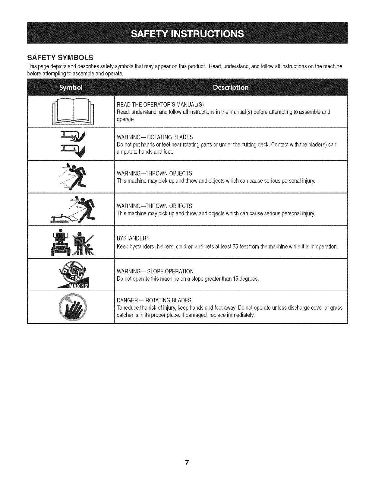
SAFETY SYMBOLS
Thispagedepictsanddescribessafetysymbolsthatmayappearonthis product. Read,understand,andfollowallinstructionson the machine
beforeattemptingto assembleandoperate.
sJ /_
®
READTHEOPERATOR'SMANUAL(S)
Read,understand,andfollowall instructionsinthe manual(s)beforeattemptingto assembleand
operate
WARNING-- ROTATINGBLADES
Donot put handsor feetnearrotatingpartsor underthe cuttingdeck.Contactwiththe blade(s)can
amputatehandsandfeet.
WARNING--THROWNOBJECTS
Thismachinemaypickupandthrowandobjectswhichcancauseseriouspersonalinjury.
WARNING--THROWNOBJECTS
Thismachinemaypickupandthrowandobjectswhichcancauseseriouspersonalinjury.
BYSTANDERS
Keepbystanders,helpers,childrenandpetsat least75feetfromthe machinewhileit is inoperation.
WARNING-- SLOPEOPERATION
Donot operatethismachineona slopegreaterthan 15degrees.
DANGER-- ROTATINGBLADES
To reducethe riskof injury,keephandsandfeetaway.Donotoperateunlessdischargecoveror grass
catcheris in itsproperplace.Ifdamaged,replaceimmediately.
7

(OK)
15° Slope X
(TOO STEEP)
15° Slope
'_. _ Figure1
USETHISSLOPEGAUGETODETERMINE
IFA SLOPEIS TOOSTEEPFORSAFEOPERATION!
To checkthe slope,proceedas follows:
1. Removethis pageandfold alongthe dashedline.
2. Locatea verticalobject onor behindthe slope (e.g.a pole, building,fence, tree,etc.)
3. Align eitherside of the slope gaugewith the object(SeeFigure1 and Figure2 ).
4. Adjust gaugeupor down until the left cornertouchesthe slope (SeeFigure1and Figure2).
5.
15°dashed line
If there is agap belowthe gauge,the slope is too steepfor safeoperation(SeeFigure2 above).
Figure2
Slopesare a majorfactor relatedto tip-over and roll-over accidents whichcan result in severe injury or death. Do not operatemachine on slopes
in excess of 15 degrees.All slopes require extra caution. If you cannot back up the slope or if you feel uneasy on it, do not mow it.
Always mow across the face of slopes, never mow up and downthe face of slopes.

SET-UP
Moving The Riding mower Manually
Yourridingmower'stransmissionisequippedwitha hydrostaticrelief
valvefor occasionswhenit isnecessaryto movethe ridingmower
manually.Openingthisvalvepermitsthe fluid inthe transmissionto
bypassitsnormalroute,allowingthe reartiresto "freewheel."Toopen
the hydrostaticreliefvalve,proceedas follows:
1. Locatethe hydrostaticbypassrodinthe rearof the ridingmower.
SeeFigure1.
RH Transmission
Bypass
PullOut Bypass
Rod ThenLower
Into Slot
Keyhole Slot
Figure1
2. Pullthe hydrostaticbypassrodoutward,then down,to lockit in
place.
3. Repeattheaboveproceduretoengagethe otherbypassrodon
theother sideof the ridingmower.
4. Withthe bypassrodsengagedandwiththe aidof anassistant,
carefullypushthe ridingmoweroff of the shippingpallet.
5. Aftermovingthe ridingmower,disengageboth bypassrods.Lift
the rodandguidethe flangeof the rod backthroughthe larger
circularopeningof the keyhole,then releasethe rod.
NOTE:The transmissionwill NOTengagewhenthe hydrostatic
bypassrodis pulledout. Returnthe rodto itsnormalpositionpriorto
operatingthe ridingmower.
Neverattemptto movethe ridingmowermanuallywithoutfirstopen-
ling the hydrostaticr,elief valve.Doingso will resultinseriousdamage
[to the ridingmowers transmission.
Removethe deckwashsystemnozzleadapterandoil draintube from
the manualbagandstoreforfutureuse.
Install Operator's Seat
Toinstallthe seatproceedas follows:
NOTE:Theseatis shippedwiththe seatswitchandseatpanattached.
1. Cutanystrapssecuringthe seatassemblyand thedrivecontrol
leversto the ridingmower.Removeanypackingmaterial.
NOTE: Becarefulnotto cut thewiring harnessconnectingtheseat
andthe seatswitch.
.
9
Removethe twoshoulderboltsandlock nutsin the seatpanas
showninFigure2.
Shoulder
Bolt
Seat Pan
Shoulder
Bolt
Figure2
Rotatethe seatintopositionandsecurethe seatinto placewith
the previouslyremovedshoulderboltsand locknuts.Becareful
not to crimpordamagethe wire harnesswhile installingthe seat.
See Figure3.
iHarness ii
Seat Bracket /
Shoulder
Bolts
Figure 3

Position Drive Control levers
Thedrivecontrolleversof the ridingmowerareloweredfor shipping
purposes.The flangelocknuts,hex screws,andflatwashersthat
normallysecurethe controlleversintheir operatingpositionare
unfastenedandinstalledinthe slottedholesof the controlleversfor
shipment.Thecontrolleversmustbe repositionedto operatethe
ridingmower.To repositionthe controlleversfor operation,proceedas
follows:
1. Removethehex screw,flat washer,andflangelocknut fromthe
slotof oneof the drivecontrollevers.
2. Liftand swingthatcontrolleverupwarduntilthe slottedholeinthe
leverbracketalignswithoneof the holesinthe pivotbracket.See
Figure4.
\
Slotted Hole
Pivot
/
\
\\
\\
Figure4
3. Slidetheflatwasherontothe hexscrew.Fromtheoutside,insert
the hexscrewwithwasherthroughthe controlleverslotandthe
holeof the pivotbracket.Securewiththe flangelocknut.See
Figure4.
4. Notethe relativepositionof the controlleverto the pivotbracket,
then repeatthe previousstepsto repositionthe othercontrollever
inapproximatelythe same position.
5. Referto "Adjustingthe DriveControlLevers"inthe Maintenance&
Adjustmentsfor instructionsonthe finaladjustmentof the levers.
Connecting the Battery Cables
Batteryposts,terminals,and relatedaccessoriescontainleadand
leadcompounds,chemicalsknownto the Stateof Californiato cause
cancerand reproductiveharm.Washhandsafter handling.
Whenattachingbatterycables,alwaysconnectthe POSITIVE(Red)
wireto itsterminalfirst,followedby the NEGATIVE(Black)wire.
Forshippingreasons,bothbatterycableson yourequipmentmay
havebeenleftdisconnectedfromthe terminalsat the factory.To
connectthe batterycables,proceedas follows:
NOTE:Thepositivebatteryterminalis markedPos.(+).The negative
batteryterminalis markedNeg.(-).
NOTE:If the positivebatterycable isalreadyattached,skipaheadto
step2.
1. Removethe plasticcover,ifpresent,fromthe positivebattery
terminalandattachthe redcableto the positivebatteryterminal
(+)withthe boltandhex nut.SeeFigure5.
Figure5
2. Removethe plasticcover,if present,fromthe negativebattery
terminalandattachthe blackcableto thenegativebattery
terminal(-) withthe boltand hexnut.SeeFig.3-5.
3. Positionthe redrubberbootoverthe positivebatteryterminalto
helpprotectitfromcorrosion.
NOTE:If the batteryis putintoserviceafterthe dateshownon top
or sideof battery,chargethe batteryas instructedinthe Serviceand
MaintenancesectionyourOperator'sManualpriortooperatingthe
ridingmower.
10

Lower Deck Discharge Chute Deflector Adjusting the Gauge Wheels
Neveroperatethe mowerdeckwithoutthe chutedeflectorinstalled
andin the downposition.
Checkthe mowerdeckfor a shippingbrace(withtag) that maybe
holdingthechutedeflectorupwardfor shipment. Ifa braceis present,
it must beremovedbeforeoperatingthe ridingmower.Holdingthe
chutedeflectorfullyupward,removethe shippingbraceby graspingit
androtatingit clockwise.Lowerthe chutedeflector.SeeFigure6.
Figure6
Checking Tire Pressure
Do notoverinfiatetires. Checksidewallof tiresfor maximumpsi.
Equaltire pressureshouldbemaintainedat alltimes.
Thetireson yourridingmowermaybeover inflatedfor shipping
purposes.Reducethe tire pressurebeforeoperatingthe ridingmower.
Checksidewallof tiresfor maximumpsi.
Keephandsandfeetawayfromthe dischargeopeningof the cutting
deck.
NOTE: Thedeckgaugewheelsarean anti-scalpfeatureof the deck
andare notdesignedto supportthe weightof the cuttingdeck.
The mowerdeckcuttingheightcan be setinanyof sixheightsettings
usingthe ridingmower'sdecklift handle.The deckheightsrangefrom
1-1/2"to 4".The deckgaugewheelpositionshouldbeapproximately
1/4"to 1/2"abovethe groundwhenthe deckissetinthedesiredheight
setting.
Usingthe lifthandle,setthe deckinthe desiredheightsetting,then
checkthe gaugewheeldistancefromthe groundbelow.If necessary
adjustasfollows:
1. Visuallycheckthe distancebetweenthefrontgaugewheelandthe
ground.Ifthe gaugewheelisnearortouchingtheground,itshould
be raised.If morethan1/2"abovetheground,itshouldbelowered.
2. Removethe flangelocknut securingthe frontgaugewheel
shoulderboltto the deck.Removethe gaugewheelandshoulder
bolt. Referto Figure7.
J
Figure7
3. Insert the shoulder bolt into the one of four index holes in the
front gauge wheel bracket that will give the gauge wheel a W'
to W' clearance with the ground and secure with the flange
locknut.
4. Note the index hole of the just adjusted wheel, and adjust the
rear gauge wheel into the respective index holes of the other
gauge wheel bracket on the deck.
11
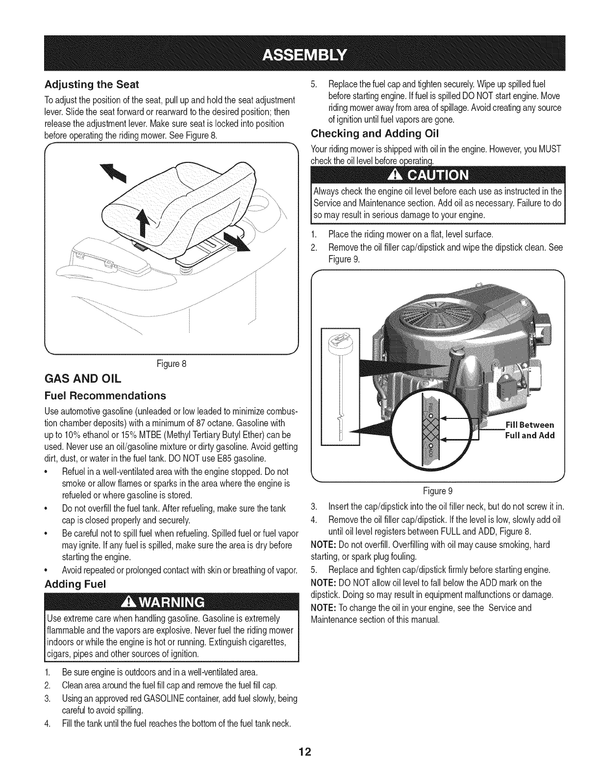
Adjusting the Seat
Toadjustthe positionof the seat,pullupand holdthe seatadjustment
lever.Slidethe seatforwardor rearwardto the desiredposition;then
releasethe adjustmentlever.Makesureseatislockedintoposition
beforeoperatingthe ridingmower.See Figure8.
Figure8
GAS AND OIL
Fuel Recommendations
Useautomotivegasoline(unleadedor low leadedto minimizecombus-
tionchamberdeposits)witha minimumof 87octane.Gasolinewith
upto 10%ethanolor 15%MTBE(MethylTertiaryButylEther)can be
used.Neveruse anoil/gasolinemixtureor dirtygasoline.Avoidgetting
dirt,dust,or waterin the fueltank. DONOTuse E85gasoline.
• Refuelina well-ventilatedareawiththe enginestopped.Donot
smokeor allowflamesor sparksinthe areawherethe engineis
refueledorwheregasolineis stored.
Do notoverfillthe fuel tank.Afterrefueling,makesurethetank
cap is closedproperlyand securely.
Becarefulnot to spill fuelwhen refueling.Spilledfuel or fuelvapor
mayignite.Ifany fuel is spilled,makesurethe areais dry before
startingthe engine.
Avoidrepeatedorprolongedcontactwithskinor breathingof vapor.
Adding Fuel
Useextremecarewhenhandlinggasoline.Gasolineisextremely
flammableandthe vaporsareexplosive.Neverfuelthe ridingmower
indoorsor whilethe engineis hot or running.Extinguishcigarettes,
cigars,pipesand othersourcesof ignition.
1. Besureengineis outdoorsandin awell-ventilatedarea.
2. Cleanareaaroundthefuelfillcap andremovethe fuelfillcap.
3. Usingan approvedredGASOLINEcontainer,addfuel slowly,being
carefulto avoidspilling.
4. Fillthetankuntilthefuel reachesthe bottomof the fueltankneck.
5. Replacethefuel capandtightensecurely.Wipeupspilledfuel
beforestartingengine.Iffuelis spilledDO NOTstartengine.Move
ridingmowerawayfromareaof spillage.Avoidcreatinganysource
of ignitionuntilfuelvaporsaregone.
Checking and Adding Oil
Yourridingmoweris shippedwithoilinthe engine.However,youMUST
checkthe engineoil levelbeforeeach useas instructedin the IAlways
Serviceand Maintenancesection.Addoilas necessary.Failureto do I
I
[so mayresut nser ous damageto yourengne. J
1. Placethe ridingmoweron a flat,level surface.
2. Removethe oilfiller cap/dipstickandwipe thedipstickclean.See
Figure9.
Figure9
3. Insertthe cap/dipstickintothe oilfiller neck,but donot screwit in.
4. Removethe oilfiller cap/dipstick.Ifthe levelis low,slowlyaddoil
untiloillevel registersbetweenFULLandADD,Figure8.
NOTE:Do notoverfill.Overfillingwithoil maycausesmoking,hard
starting,or sparkplugfouling.
5. Replaceandtightencap/dipstickfirmly beforestartingengine.
NOTE:DO NOTallowoil levelto fall belowthe ADDmarkonthe
dipstick.Doingso mayresultinequipmentmalfunctionsor damage.
NOTE:Tochangethe oil inyour engine,seethe Serviceand
Maintenancesectionof thismanual.
12

Parking
Deck Lift
Deck Height Handle
O
Throttle/Choke Control
Hour Meter/
indicator Panel
SeatAdjustmentLever
FuelTankCap
H
// _ /-PTOSwitch
LH Drive RH Drive nition Switch
Control Lever Control Lever
Cup Holder
Storage Tray
Figure11
Nowthat youhavesetup yourridingmower,it'simportantto become
acquaintedwith itscontrolsandfeatures.Referto Figure11.
NOTE:Referencesto LEFT,RIGHT,FRONT,andREARindicatethatposi-
tionontheridingmowerwhenfacingforwardwhileseatedintheoperator's
seat.
DECK HEIGHT INDEX
Thedeckheightindexconsistsof sixindexnotcheslocatedon
thefront!rightdtheseatboxframe.Eachnotchcorrespondsto
a 1/2"changein thedeckheightpositionrangingfrom1-1/2"at
thelowest notchto 4 inchesat the highestnotch.
DECK LIFT HANDLE
Thedecklift handleis locatedon the front!rightof the seat
boxframe,andis usedto raiseand lowerthe mowerdeck.
Pullthe handleto the leftoutof the indexnotchandpush
downwardto lowerthedeck,or pullupwardto raisethe deck.
Whenthedesiredheightisattained,movethe lifthandleto the
rightuntilfullyinthe indexnotch.
CUP HOLDER
Thecup holderis locatedtowardthe rearof the RHconsole
to the rightof the operator'sseat.
STORAGE TRAY
The storagetrayislocatedat the rearof the RHconsole.
RH AND LH DRIVE CONTROL LEVERS
The RHandLH controlleversarelocatedon eachsideof the opera-
tor's seat.Thesehingedleverspivotoutwardto openspaceto permit
the operatorto either sitinthe ridingmowerseat,orto dismountthe
ridingmower.Theleversmust befullyopenedoutand inthe neutral
positionto startthe ridingmowerengine.
Eachlevercontrolsthe respectiveRHorLH transmission.Conse-
quently,theseleverscontrolallof the movementsof the ridingmower.
Drivingand steeringutilizingthesecontrolleversisquitedifferentfrom
conventionalridingmowers,andwill takesomepracticeto master.
Referto the Drivingthe Ridingmowersectionfor instructionsonusing
the controllevers.
Meets ANSI Safety Standards
CraftsmanTillersconformto the safetystandardof the AmericanNationalStandardsInstitute(ANSI)
13
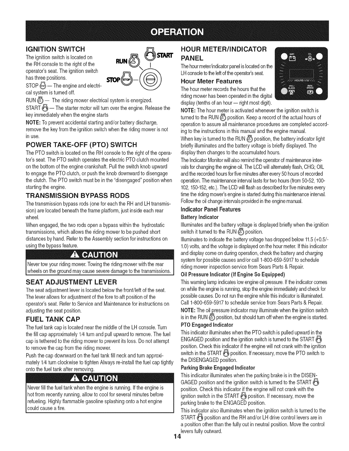
iGNiTiON SWITCH
Theignitionswitchis locatedon
the RHconsoleto the rightof the
operator'sseat.Theignitionswitch
hasthree positions.
STOP_ -- Theengineandelectri-
cal systemis turnedoff.
RUN_ I
RUN_ -- The ridingmowerelectricalsystemisenergized.
START_ -- The startermotorwill turn overtheengine.Releasethe
keyimmediatelywhenthe enginestarts
NOTE:Topreventaccidentalstartingand/or batterydischarge,
removethe keyfromthe ignitionswitchwhenthe ridingmowerisnot
inuse.
POWER TAKE-OFF (PTO) SWITCH
The PTOswitchislocatedonthe RH consoleto the rightof the opera-
tor's seat.The PTOswitchoperatestheelectric PTOclutchmounted
onthe bottomof theenginecrankshaft.Pullthe switchknobupward
to engagethe PTOclutch,or pushtheknob downwardto disengage
the clutch.The PTOswitchmustbeinthe "disengaged"positionwhen
startingthe engine.
TRANSMiSSiON BYPASS RODS
Thetransmissionbypassrods(onefor eachthe RHandLH transmis-
sion)arelocatedbeneaththe frameplatform,justinsideeach rear
wheel.
Whenengaged,the two rodsopena bypasswithinthe hydrostatic
transmissions,whichallowsthe ridingmowerto be pushedshort
distancesby hand.Referto the Assemblysectionfor instructionson
usingthe bypassfeature.
Nevertowyourridingmower.Towingthe ridingmowerwiththe rear
wheelsonthe groundmaycauseseveredamageto thetransmissions.
SEAT ADJUSTMENT LEVER
Theseatadjustmentleveris locatedbelowthefront!leftof the seat.
Theleverallowsfor adjustmentof the foreto aft positionof the
operator'sseat.Referto Serviceand Maintenancefor instructionson
adjustingthe seatposition.
FUEL TANK CAP
Thefuel tankcap islocatednearthe middleof the LH console.Turn
the fill capapproximately1/4turnandpull upwardto remove.The fuel
cap istetheredto the ridingmowerto preventitsloss.Do notattempt
to removethe cap fromthe ridingmower.
Pushthecap downwardonthe fuel tankfill neckand turnapproxi-
mately1/4turn clockwiseto tightenAlwaysre-installthe fuelcap tightly
ontothe fueltankafter removing.
Neverfill the fueltankwhenthe engineis running.Ifthe engineis
hotfrom recentlyrunning,allowto coolfor severalminutesbefore
refueling.Highlyflammablegasolinesplashingontoa hot engine
couldcausea fire.
HOUR METER/INDICATOR
PANEL
Thehourmeter/indicatorpanelis locatedonthe
LHconsoletotheIdtoftheoperator'sseat.
Hour Meter Features
The hourmeterrecordsthe hoursthatthe
ridingmowerhasbeenoperatedinthe digital
display(tenthsof anhour-- rightmostdigit).
NOTE:Thehourmeteris activatedwheneverthe ignitionswitchis
turnedto the RUN_ position.Keepa recordof the actualhoursof
operationto assureall maintenanceproceduresarecompletedaccord-
ingto the instructionsinthis manualandthe enginemanual.
Whenkeyis turnedto the RUN_ position,the batteryindicatorlight
brieflyilluminatesandthe batteryvoltageis brieflydisplayed.The
displaythen changesto the accumulatedhours.
TheIndicatorMonitorwillalsoremindtheoperatordmaintenanceinter-
valsforchangingtheengineoil.TheLCDwillalternatelyflash,CHG;OIL
andthe recordedhoursforfiveminutesafterevery50hoursof recorded
operation.Themaintenanceintervallastsfortwohours(from50-52,100-
102,150-152,etc.).The LCDwillflashasdescribedforfiveminutesevery
timethe ridingmower'sengineis startedduringthismaintenanceinterval.
Followtheoilchangeintervalsprovidedintheenginemanual.
indicator Panel Features
Battery Indicator
Illuminatesandthe batteryvoltageis displayedbrieflywhenthe ignition
switchit turnedto the RUN_ position.
Illuminatesto indicatethe batteryvoltagehasdroppedbelow11.5(+0.5/-
1.0)volts,andthe voltageis displayedonthe hourmeter.Ifthisindicator
anddisplaycomeonduringoperation,checkthe batteryandcharging
systemforpossiblecausesand/orcall 1-800-659-5917to schedule
ridingmowerinspectionservicefromSearsParts& Repair.
Oil PressureIndicator (if EngineSo Equipped)
Thiswarninglampindicateslowengineoilpressure,if theindicatorcomes
onwhiletheengineis running,stoptheengineimmediatelyandcheckfor
possiblecauses.Donotruntheenginewhilethisindicatorisilluminated.
Call1-800-659-5917to scheduleservicefromSearsParts& Repair.
NOTE:Theoil_ressureindicatormayilluminatewhenthe ignitionswitch
isin the RUNO position,butshouldturnoffwhentheengineis started.
PTOEngagedIndicator
Thisindicatorilluminateswhenthe PTOswitchis pulledupwardinthe
ENGAGEDpositionandthe ignitionswitchis turnedtothe START
position.Checkthisindicatorif theenginewillnotcrankwiththeignition
switchinthe START_ position.Ifnecessary,movethe PTOswitchto
the DISENGAGEDposition.
ParkingBrake Engaged Indicator
Thisindicatorilluminateswhenthe parkingbrakeis in the DISEN-
GAGEDpositionandthe ignitionswitchis turnedtothe START
position.Checkthis indicatorif the enginewill not crankwiththe
ignitionswitchin the START_ position.Ifnecessary,movethe
parkingbraketo the ENGAGEDposition.
Thisindicatoralsoilluminateswhenthe ignitionswitchis turnedto the
START_ positionandthe RHand/or LHdrivecontrolleversare in
a positionotherthanthe fullyout in neutralposition.Movethe control
leversfullyoutward.
14
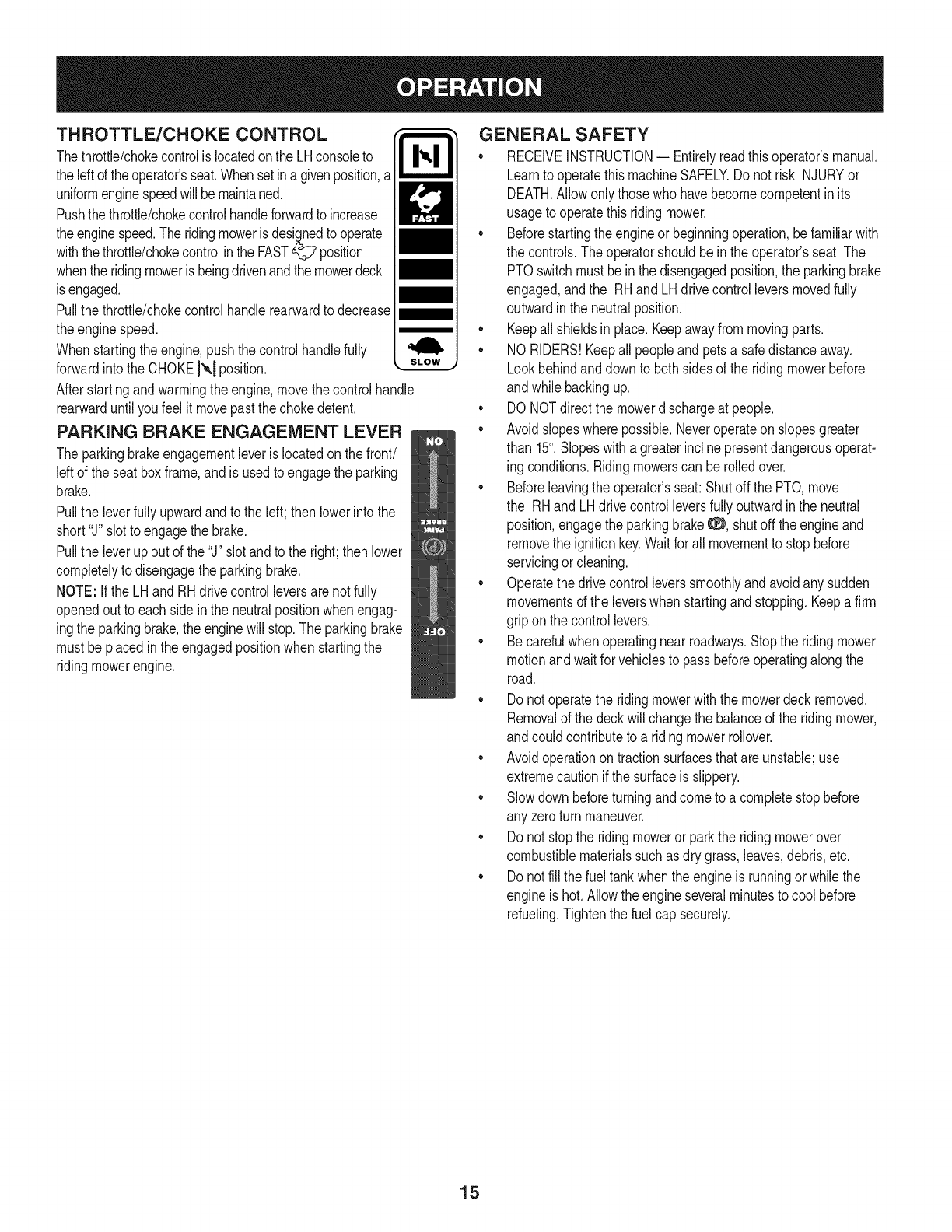
THROTTLE/CHOKE CONTROL
Thethrottle/chokecontrolis locatedonthe LHconsoleto
theleftof theoperator'sseat.Whensetina givenposition,a
uniformenginespeedwill bemaintained.
Pushthe throttle/chokecontrolhandleforwardto increase
theenginespeed.The ridingmowerisdesignedto operate
withthe throttle/chokecontrolinthe FAST_ position
whenthe ridingmoweris beingdrivenandthe mowerdeck
is engaged.
Pullthe throttle/chokecontrolhandlerearwardto decrease
theenginespeed.
Whenstartingthe engine,push thecontrolhandlefully
forwardintothe CHOKEI'_,1position.
Afterstartingandwarmingtheengine,movethe controlhandle
rearwarduntilyoufeel it movepastthechokedetent.
PARKING BRAKE ENGAGEMENT LEVER
The parkingbrakeengagementleveris locatedonthe front/
leftof the seatboxframe,andis usedto engagethe parking
brake.
Pullthe leverfullyupwardandtothe left;then lowerintothe
short"J"slotto engagethe brake.
Pullthe leverupout of the"J"slotandto the right;then lower
completelyto disengagethe parkingbrake.
NOTE: Ifthe LH andRHdrivecontrolleversarenot fully
openedoutto eachsidein the neutralpositionwhenengag-
ingthe parkingbrake,the enginewill stop.The parkingbrake
mustbe placedin the engagedpositionwhenstartingthe
ridingmowerengine.
GENERAL SAFETY
• RECEIVEINSTRUCTION-- Entirelyreadthisoperator'smanual.
Learnto operatethismachineSAFELY.Do not riskINJURYor
DEATH.Allowonlythosewho havebecomecompetentin its
usageto operatethis ridingmower.
• Beforestartingthe engineor beginningoperation,be familiarwith
the controls.Theoperatorshouldbein the operator'sseat.The
PTOswitchmustbein the disengagedposition,the parkingbrake
engaged,andthe RHand LHdrivecontrolleversmovedfully
outwardin the neutralposition.
• Keepallshieldsin place.Keepawayfrommovingparts.
• NORIDERS!Keepall peopleandpetsa safedistanceaway.
Lookbehindand downto bothsidesof the ridingmowerbefore
andwhile backingup.
• DONOTdirectthe mowerdischargeat people.
• Avoidslopeswherepossible.Neveroperateon slopesgreater
than 15°. Slopeswitha greaterinclinepresentdangerousoperat-
ing conditions.Ridingmowerscan be rolledover.
• Beforeleavingthe operator'sseat:Shutoff the PTO,move
the RHand LHdrivecontrolleversfullyoutwardin the neutral
position,engagethe parkingbrake_:_, shutoff the engineand
removethe ignitionkey.Waitfor all movementto stopbefore
servicingor cleaning.
• Operatethe drivecontrolleverssmoothlyandavoidanysudden
movementsof the leverswhenstartingandstopping.Keepa firm
gripon the controllevers.
• Becarefulwhenoperatingnearroadways.Stopthe ridingmower
motionandwaitfor vehiclesto passbeforeoperatingalongthe
road.
• Donot operatethe ridingmowerwiththe mowerdeckremoved.
Removalof the deckwillchangethe balanceof the ridingmower,
andcouldcontributeto a ridingmowerrollover.
• Avoidoperationontractionsurfacesthatare unstable;use
extremecautionif the surfaceis slippery.
• Slowdown beforeturningandcometo a completestopbefore
any zeroturn maneuver.
• Donot stopthe ridingmoweror parkthe ridingmowerover
combustiblematerialssuchas dry grass,leaves,debris,etc.
• Donot fill the fueltankwhenthe engineis runningor whilethe
engineis hot.Allowtheengineseveralminutesto cool before
refueling.Tightenthe fuel cap securely.
15
BEFORE OPERATING YOUR RiDiNG MOWER
•Beforeyou operatethe ridingmower,studythismanualcarefully
to familiarizeyourselfwiththe operationof allthe instrumentsand
controls.Ithas beenpreparedto helpyouoperateand maintain
yourridingmowerefficiently.
•Thisengineiscertifiedtooperateonlyonclean,fresh,unleadedregu-
largasoline.Forbestresults,fill thefueltankwithonlyclean,fresh,
unleadedgasolinewitha pumpstickeroctaneratingof87orhigher.
• Unleadedgasolineis recommendedbecauseit leavesless
combustionchamberdepositsand reducesharmfulexhaust
emissions.Leadedgasolineis not recommendedand mustnotbe
usedwhereexhaustemissionsareregulated.
NOTE:Purchasegasolineinsmallquantities.Donotusegasolineleftover
fromthe previousseason,tominimizegumdepositsinthefuelsystem.
•Gasohol(upto 10%ethylalcohol,90% unleadedgasolineby
volume)is anapprovedfuel.Othergasoline/alcoholblendsare
not approved.
•MethylTertiaryButylEther(MTBE)andunleadedgasolineblends
(upto a maximumof 15%MTBEby volume)areapprovedfuels.
Othergasoline/etherblendsarenotapproved.
•Checktheengineoil level.
• Cleantheair cleanerelementif necessary.
•Checkthetire inflationpressures.
•Adjustthe seatforoperator'smaximumcomfort,visibilityandfor
maintainingcompletecontrolof the ridingmower.
SAFETY iNTERLOCK SYSTEM
Thisridingmowerisequippedwitha safetyinterlocksystemfor the
protectionofthe operator.Ifthe interlocksystemshouldevermalfunc-
tion,do not operatethe ridingmower.Call 1-800-659-5917to schedule
servicefromSearsParts& Repair.
•Thesafetyinterlocksystempreventsthe enginefromcranking
orstartingunlessthe RHand LHdrivecontrolleversare moved
fullyoutwardto each sidein the neutralposition,the parking
brakeisengaged,andthe PTOis disengaged.
•Toavoidsuddenmovementwhendisengagingthe parkingbrake,
the safetyinterlocksystemwill shutoffthe engineif the RHand/
or LHdrivecontrolleversare movedto a positionotherthan
the fullyout inthe neutralpositionwhenthe parkingbrakeis
engaged.
•Thesafetyinterlocksystemwill shutoffthe engineifthe operator
leavesthe seatbeforeengagingthe parkingbrake.
•Thesafetyinterlocksystemwill shutoffthe engineifthe operator
leavesthe seatwiththe PTOengaged,regardlessof whetherthe
parkingbrakeis engaged.
NOTE:The PTOswitchmustbe movedto the "OFF"positionto restart
the engine.
•Thesafetyinterlocksystemwill shutoffthe PTOandthe mower
bladeswillstopif bothdrivecontrolleversare movedintothe
reverseposition.The PTOwill re-engagewhenoneor bothof the
leversaremovedbacktoeither the neutralorforwardposition.
STARTING THE ENGINE
Thisridingmoweris equippedwitha safetyinterlocksystemdesignee
for the protectionof the operator.Donotoperatethe ridingmowerif
any partof the interlocksystemis malfunctioning.Periodicallycheck
the functionsof the interlocksystemfor properoperation.
Forpersonalsafety,theoperatormustbesitting inthe ridingmower
seatwhenstartingtheengine.
16
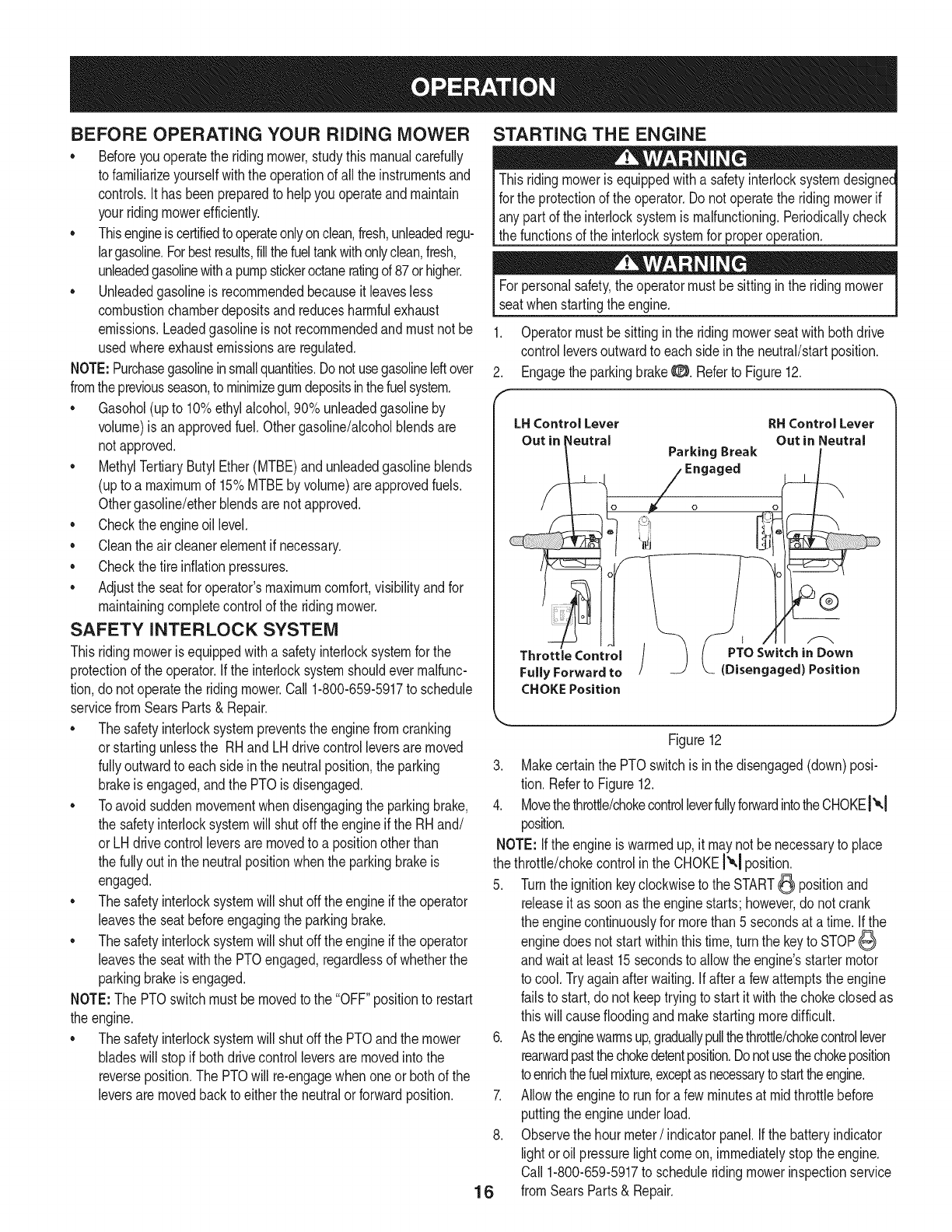
1. Operatormust besittinginthe ridingmowerseatwithbothdrive
controlleversoutwardto each sidein the neutral/startposition.
2. Engagethe parkingbrakeO. Referto Figure12.
LHControlLever RHControlLever
Out in I_eutral Out in Neutral
ParkingBreak
-- Engaged
Throttle Control / ( PTOSwitchinDown
FullyForwardto /__ (Disengaged)Position
CHOKEPosition
Figure12
3. Makecertainthe PTOswitchis in the disengaged(down)posi-
tion. Referto Figure12.
4. Movethethrottle/chokecontrolleverfullyforwardintotheCHOKEt"°,1
position.
NOTE:Ifthe engineiswarmedup,it maynot be necessaryto place
the throttle/chokecontrolin the CHOKE!'_1position.
5. Turnthe ignitionkeyclockwiseto the START_ positionand
releaseit as soonas the enginestarts; however,do not crank
the enginecontinuouslyfor morethan 5 secondsat a time.If the
enginedoes not startwithinthis time,turnthe keyto STOP
andwait at least 15secondsto allowthe engine'sstartermotor
to cool.Tryagainafterwaiting.Ifaftera fewattemptsthe engine
failsto start,do not keeptryingto start it withthe chokeclosedas
thiswill causefloodingandmakestartingmoredifficult.
6. Astheenginewarmsup,graduallypullthethrottle/chokecontrollever
rearwardpastthechokedetentposition.Donotusethechokeposition
toenrichthefuelmixture,exceptas necessarytostarttheengine.
7. Allowthe engineto runfor a fewminutesat mid throttlebefore
puttingtheengineunderload.
8. Observethe hourmeter/indicatorpanel.Ifthe batteryindicator
lightoroil pressurelightcomeon, immediatelystopthe engine.
Call1-800-659-5917to scheduleridingmowerinspectionservice
fromSearsParts& Repair.

Cold WeatherStarting
Whenstartingtheengineattemperaturesnearorbelowfreezing,
ensurethecorrectviscositymotoroilisusedintheengineandthe
batteryisfullycharged.Starttheengineasfollows:
1. Besurethebatteryisingoodcondition.Also,awarmbatteryhas
muchmorestartingcapacitythanacoldbattery.
2. Usefreshwintergradefuel.Wintergradegasolinehashighervolatility
toimprovestarting.Donotusegasolineleftoverfromsummer.
3. FollowthepreviousinstructionforStartingtheEngine.
Using Jumper CablesTo Start Engine
Batteriescontainsulfuricacid andproduceexplosivegasses.Make
certainthe areais wellventilated,wearglovesandeyeprotection,
land avod sparksor f amesnearthe battery.
Ifthe batterychargeis not sufficientto cranktheengine,rechargethe
battery.Ifa batterychargeris unavailableandthe ridingmowermust
be started,the aidof aboosterbatterywill benecessary.Connectthe
boosterbatteryas follows:
1. Connectthe endof onecableto the disabledridingmowerbat-
tery'spositiveterminal;then connectthe otherendof thatcableto
the boosterbattery'spositiveterminal.
2. Connectoneendofthe othercableto theboosterbattery'snega-
tiveterminal;thenconnecttheotherendof thatcabletothe frame
of thedisabledridingmower,as farfromthe batteryas possible.
3. Startthe disabledridingmowerfollowingthe normalstarting
instructionspreviouslyprovided;thendisconnectthe jumper
cablesin theexact reverseorderof theirconnection.
4. Havethe ridingmower'selectricalsystemcheckedand repaired
as soonas possibleto eliminatethe needfor jump starting.
STOPPING THE ENGINE
1. Placethe PTOswitchinthe OFFposition.
2. Movethe RHand LHdrivecontrolleversfullyoutwardinthe
neutralposition.
3. EngagetheparkingbrakeO.
4. Movethethrottle/chokecontroltomidwaybetweenthe SLOW'_
andFAST_ positions.
5. Turnthe ignitionkeytothe STOP_ positionand removethe key
fromthe ignitionswitch.
NOTE:Alwaysremovethe keyfromthe ignitionswitchto preventacci-
dentalstartingor batterydischargeif the equipmentis left unattended.
PRACTICE OPERATION (INITIAL USE)
Operatinga zero-turnridingmoweris notlikeoperatingaconventionaltype
ridingridingmower.Becausea zeroturnridingmoweris moremaneuver-
able,gettingusedtooperatingthecontrolleverstakessomepractice.
Westronglyrecommendthatyoulocatea reasonablylarge,levelandopen
"practicearea"wheretherearenoobstructions,pedestrians,oranimals.You
shouldpracticeoperatingtheridingmowerforaminimumof30minutes.
Carefullymove-- orhaveanexperiencedusermove--the ridingmower
to thepracticearea.Whenperformingthe practicesession,the PTO
shouldnotbeengaged.Whilepracticing,operatethe ridingmower
atapproximately1/2to 3/4throttleandat lessthanfull speedinboth
forwardandreverse.
Carefullypracticemaneuveringtheridingmowerandproceedto driveas
describedin thefollowingDrivingtheRidingmowerForwardsection.
DRIVING THE RIDING MOWER
Avoidsuddenstarts,excessivespeedand suddenstops, j
1. Adjustthe operator'sseatto the mostcomfortablepositionthat
allowsyou to operatethe controls.See"Adjustingthe Seat" the
Assemblysection.
2. ReleasetheparkingbrakeO.
3. Movethe RHand LHdrivecontrolleversinwardin the neutral
position.Referto Figure13.
Control Lever Moved
inward and in Neutral
/Q
Figure13
NOTE: Ifthe controlleversarenoteven in the neutralposition,refer
to ServiceandMaintenancefor instructionsto adjustthe leversso that
theyareeven.
4. Movethethrottle/chokecontrolleverforwardto the FAST
(full throttle)position.
NOTE: Althoughthe ridingmower'sengineis designedto runat full
throttle,when performinga practicesessionthe ridingmowermustbe
operatedat lessthan fullthrottle.Thisonly appliesto practice.
Alwaysmaintainafirm gripon the controllevers.DONOTreleasethe
controlleversto slowor stopthe ridingmower;moveleversto neutral
positionusingyour hands.
5. Todrive the ridingmower,firmlygraspthe respectivedrivecontrol
leverswithyour rightandleft handsandcontinuewithDrivingthe
RidingmowerForwardon the followingpage.
17

Driving the Riding mower Forward
Keepall movementof the drivecontrolleversslowandsmooth.
Abrupt movementof the controlleverscan affectthe stabilityof the
ridingmowerandcouldcausethe ridingmowerto flip over,which
mayresultin seriousinjury ordeathto the operator.
Slowlyandevenlymovebothdrive controlleversforward.The
ridingmowerwill startto moveforward.SeeFigure14.
r
Driving Forward
Faster
Figure14
2. As thecontrolleversarepushedfartherforwardthe speedof the
ridingmowerwill increase.
3. Toslowthe ridingmowermovethe controlslever rearwardto
attainthe desiredspeed,ormovethe leversto the neutralposition
to stopthe ridingmower.
Alwaysmaintainyourgraspon the drivecontrollevers.Donot release
the leversto slowthe ridingmowerorto returnto neutral.
Turning the Riding mower While Driving Forward
Whenreversingthe directionof travel,we recommendperforming
gradual'U' turnswherepossible.Sharperturnsincreasethe possibil-
ity of turfdefacement,andcouldaffectcontrolof the ridingmower.
ALWAYSslowthe ridingmowerbeforemakingsharpturns.
Toturn the ridingmowerwhiledrivingforward,movethe controllevers
as necessarysothat oneleveris rearwarddthe other.The riding
mowerwill turn inthe directionof the rearwardcontrollever.
1. Toturn to the left, movethe leftdrivecontrolleverrearwardof the
rightlever.SeeFigure15.
Figure15
2. Toturn to the right,movethe rightdrivecontrollever rearwardof
the left lever.SeeFigure16.
W
ForwardRightTurn F
-oZ-
18
Figure16
3. The greaterthe fore-to-aftdistancebetweenthe twolevers,the
sharperthe ridingmowerwill turn.

4. Toexecuteazeroturnmovetheturnsidedrivecontrolleverto
theinwardneutralposition,whilemovingtheothercontrollever
forward.
NOTE:Makingazeroturnongrasswillgreatlyincreasethepotential
fordefacementoftheturf.
Driving the Riding mower in Reverse
1. Slowlyandevenlymovebothdrivecontrolleversrearward.The
ridingmowerwill start to moveinthe reversedirection.SeeFigure
17.
.
F
Turning While Driving Rearward
1. Toturn the ridingmowerwhiledrivingrearward,movethe control
leversas necessaryso thatoneleverisforwardof the other.The
ridingmowerwill turninthedirectionof the forwardcontrollever.
Toturn to the leftwhiletravelinginreverse,movethe left drive
controlleverforwardof the rightlever.See Figure18.
Rearward Left Turn
0
®
.
f
Figure18
Toturn to the rightwhiletravelinginreverse,movethe rightdrive
controlleverforwardof the left lever.SeeFigure19.
.
3.
Figure17
As thecontrolleversarepushedfartherrearwardthe speedof the
ridingmowerwill increase.
Toslowthe ridingmowermovethe controlsleverforwardto attain
thedesiredspeed,or movethe leversto the neutralpositionto
stopthe ridingmower.
Rearward Right Turn
0
Figure19
4. The greaterthe fore-to-aftdistancebetweenthe twolevers,the
sharperthe ridingmowerwillturn.
5. Toexecutea zeroturn,movethe turn sidedrivecontrolleverto
the neutralposition,whilemovingtheother controlleverrearward.
NOTE: Makinga zeroturnon grasswill greatlyincreasethe potential
for defacementofthe turf.
19

Executing aZero Turn
When executinga zeroturn,the ridingmowerMUSTBESTOPPED.
Executinga zeroturn whilethe ridingmoweris movingcan signifi-
cantly reduceyourcontrolof the ridingmowerandwill causesevere
turf defacementto occur.
Stopthe forwardor reversemotionof the ridingmowerby moving
the twodrivecontrolleversto neutral.
2. Toturnclockwise,movethe leftcontrolleverforwardwhilesimulta-
neouslymovingthe rightcontrolleverrearward.SeeFigure20.
Clockwise Zero Turn
Figure20
3. Toturncounterclockwise,movethe rightcontrolleverforwardwhile
simultaneouslymovingtheleftcontrolleverrearward.SeeFigure21.
Counterclockwise
Zero Turn
2. Pushthe PTOswitchdownwardto the DISENGAGEDposition.
3. Usethe decklift handleto raisethe deckto itshighestposition.
4. Ifdismountingthe ridingmower,movethe drivecontrolleversfully
outwardintheneutralposition,engagethe parkingbrakeO, move
the throttle/chokecontrolleverto the FAST_ position,turnthe
ignitionswitchto STOP_ and removethe keyfromthe switch.
Donot leavethe seatof the ridingmowerwithoutdisengagingthe
PTO, movingdrivecontrolleversfullyoutwardinthe neutralposition,
andengagingthe parkingbrake.If leavingthe ridingmowerunat-
tended,turnthe ignitionkeyoffand removekey.
DRIVING ON SLOPES
Referto the slopegaugeinthe SafeOperationSectionto help
determineslopeswhereyou maynot operatesafely.
Donot operateon inclineswitha slopein excessof 15degrees(a
riseof approximately2-1/2feetevery10feet).The ridingmowercould
overturnandcauseseriousinjury.
1. Alwaysdrive acrossslopes,neverupanddown.Controlthe
speedanddirectionof the ridingmowerusing primarilythe control
leveron thedownhillsideof the ridingmower,withthe uphill
controlleverremainingessentiallyina fixedposition.
2. Avoidturningdownhillif possible.Startat the bottomof a slope
andworkupward.Alwaysslowdownbeforeturning.
3. Useextracareandgo slowlywhenturningdownhill.
OPERATING THE PTO
Operatethe PTOclutchas follows:
1. Movethe throttle/chokecontrolleverto approximatelythe mid
throttleposition.
2. Pullthe PTOswitchupwardto the ENGAGEDposition.
3. Advancethethrottle/chokeleverto the FAST_ position(full
throttle).
4. The operatormustremaininthe ridingmowerseatat all times.If
the operatorshouldleavethe seatwithoutturningoffthe power
take-offswitch,the ridingmower'senginewill shutoff.
5. The PTOclutchcannotbeoperatedwhenthe ridingmoweris
drivinginthe reversedirection.The PTOwilldisengagewhen
bothdrivecontrolleversaremovedto the reverseposition,and
will re-engagewhenone(or both)controllever(s)is movedto the
neutralorforwardposition.
Figure21
STOPPING THE RIDING MOWER
1. Movebothdrivecontrolleversto the neutralpositionto stopthe
motionof the ridingmower. 20

USING THE MOWER DECK
l Makecertainthe areato be mowedisfree of debris,sticks,stones, I
wireorother objectsthatcan bethrownby the rotatingblades. ]
NOTE: Donot engagethe mowerdeckwhenloweredingrass.
Prematurewearand possiblefailureof the 'V" beltand PTOclutch
will result.Fullyraisethe deckormovetoa non-grassyareabefore
engagingthe mowerdeck.
1. Mowacrossslopes,not upanddown.Ifmowinga slope,startat
bottomandwork upwardto ensureturnsaremadeuphill.
2. Onthe first passpicka pointon the oppositesideof the areato
be mowed.
3. Engagethe PTOclutchusingthe PTOswitchand movethe
throttle/chokecontrolto the FAST_ position.
4. Lowerthe mowerdeckto the desiredheightsettingusingthe lift
handle.
5. Slowlyandevenlypushthe RHandLH drivecontrollevers
forwardto movethe ridingmowerforward,and keepthe riding
mowerheadeddirectlytowardthe alignmentpoint.
NOTE:The speedof the ridingmowerwill affectthe qualityof the
mowercut. Mowingat full speedwilladverselyaffectthecut quality.
Controlthegroundspeedwiththe controllevers.
6. Whenapproachingtheotherendof thestrip, slowdownor stop
beforeturning.A U-turnis recommendedunlessa zeroturn is
required.
7. Alignthe mowerwithan edgeof the mowedstripandoverlap
approximately3".
8. Directthe ridingmoweroneach subsequentstripto alignwitha
previouslycut strip.
9. Topreventruttingor groovingof theturf, if possible,changethe
directionthatthe stripsare mowedby approximately450for the
nextandeachsubsequentmowing.
Becarefulwhencrossinggravelpathsor driveways.Disengagethe
PTOandraisethe deckto the highestpositionbeforecrossing. l
NOTE:Whenstoppingthe ridingmowerfor any reasonwhileona
grasssurface,always:
• Placethecontrolleversinneutral,
• Engagethe parkingbrake8,
• Shutengineoff andremovethe key.
• Doingso will minimizethe possibilityof havingyourlawn
"browned"by hotexhaustfromyourridingmower'srunning
engine.
CHECKING SAFETY iNTERLOCK CiRCUiTS
Periodicallycheckthe safetyinterlockcircuitsto ensuretheyare
workingproperly.If a safetycircuitis notworkingas designed,call
1-800-659-5917to scheduleridingmowerinspectionservicefrom
Sears Parts& Repair.DO NOToperatethe ridingmowerif any safety
circuitis notfunctioningproperly.Tocheckthe safetycircuits,proceed
as follows:
1. Sittingin the ridingmowerseatwith bothdrivecontrollevers
openedfullyoutward,DISENGAGEthe parkingbrake0 and
momentarilyturn the ignitionswitchto the START_ position.
The engineshouldnotcrank.
2. Engagethe parkingbrake0 andpullthe PTOswitchupwardto
the ENGAGEDposition.Momentarilyturn the ignitionswitchto
the START_ position;the engineshouldnotcrank.
3. Pushthe PTOswitchdownwardto the DISENGAGEDposition
and ENGAGEthe parkingbrake0. Startthe engineandmove
oneof the drivecontrolleversfromthe fullyoutwardneutral
position.Theengineshouldstoprunning.Repeatthe procedure
withthe oppositecontrollever.
4. Movebothcontrolleversfullyoutwardinthe neutralpositionand
DISENGAGEthe parkingbrake0; then liftupwardfromthe
operator'sseat.The engineshouldstop.
5. Withbothcontrolleversfullyoutwardin the neutralpositionand
the parkingbrakeENGAGED0, ENGAGEthe PTO.Liftupward
fromthe operator'sseat;the engineshouldstop.
6. Startthe ridingmower,DISENGAGEthe parkingbrake0, and
movethecontrolleversinwardto the neutraloperatingposition.
ENGAGEthe PTOand movebothcontrolleverslowlyintothe
slowreverseposition;the PTOshoulddisengageandthe mower
deckshouldstopuntiloneor bothof the controlleversis moved
to the neutralorforwardposition.
21

MAINTENANCE SCHEDULE
Beforeperforminganytypeof maintenance/service,disengageall
controlsandstopthe engine.Waituntilall movingpartshavecome
to acompletestop. Disconnectsparkplugwireand groundit against
theengineto preventunintendedstarting.Alwayswearsafetyglasses
duringoperationorwhile performingany adjustmentsor repairs.
Eachuse
Every25 hours
Every50 hours
Every100hours
Every500 hours
Everyseason/Before
storage
Aftermowing
Once Monthly
1. Engineoillevel.
2. Gasoline
3. Mowerand exhaustarea
4. HydraulicTransaxle
5. Tiresand pressure
6. Deck,moweranddrivebelts
7. Bladesand bolttightness
8. Safetyswitchoperation
1. Pre-Cleaner
2. SpindleBearings
3. SparkPlug
1. WearPoints
2. Greasefitting
1. AirCleaner
2. Oilandfilter
3. Coolingshroudsandcooling
areas
4. FuelFilter
5. Sparkplug
6. Fastenersand components
1. Sparkplug
1. Pivotpoints
2. Controlhandle
3. Extensionspring
1. EngineIntakeScreen/Cover
2. Mowerand exhaustarea
3. Wearpoints
1. SpindlePulleys
2. V-Belt
Followthe maintenanceschedulegivenbelow.Thischartdescribes
serviceguidelinesonly.UsetheServiceLogcolumnto keeptrack
of completedmaintenancetasks.To schedule service from Sears
Parts& Repair,call 1-800-659-5917,,
1. Check
2. Check
3. Clean
4. Checkfor leaks
5. Check
6. Check
7. Check
8. Check
1. Service/Replace
2. Grease
3. Check
1. Lubricate
2. Lubricate
1. Replace
2. Change
3. Removeandclean
4. Replace
5. Change
6. Checkandsecure
1. Replaceandsetgap
1. Lubricate
2. Lubricate
3. Lubricate
4. Check
5. Clean
6. Lubricate
1. Clean
2. Clean
22

Beforeperformingany maintenanceor repairs,disengagethe PTO,
movethe drivecontrolleversfullyoutwardinthe neutralposition,
engagethe parkingbrake,stoptheengineand removethe keyto
preventunintendedstarting.
Draining the Oil
1. Runthe enginefor a shorttimeto warmthe engineoil. The oil
will flowmorefreelyandcarryawaymoreimpurities.Usecare to
avoidburnsfromhotoil.
2. Locatetheoildrainvalveontheleftsideof theengine.SeeFigure22.
ENGINE MAINTENANCE
Thoroughlywashyourhandswithsoapandwateras soon as
possibleafterhandlingusedoil.
Check Engine Oil
1. Checkoilbeforeeachuse.Stopengineandwaitseveralminutes
beforecheckingoil level.Withengineon levelground,the oil must
beto FULLmarkon dipstick.
2. Referto the Assemblysectionof thismanualfor instructionson
checkingthe oil.
Change Engine Oil and Filter
•Referto the viscositychart(Figure21)for oil recommenda-
tions.Do notoverfill.SAE30 is recommendedfor general,all
temperatureuse.Usea 4-stroke,or anequivalenthighdetergent,
premiumqualitymotoroilcertifiedto meetor exceedU.S.
automobilemanufacturer'srequirementsfor serviceclassification
SF,SG,SH,SJ or higher.Motoroils classifiedSF,SG,SH,SJ will
showthisdesignationon thecontainer.
a6 .
50
_4
°22
4O
iU L:F ¸3o
i...................................................................20
C
C
>
0
10
_20
-30
-- Below 40 °F(4 ° C) the use of SAE 30W will result in hard starting.
** -- Above 80 °F (27 ° C) the use of 10W-30 may cause increased oil consumption,
Check the oil level more frequently,
Figure21
NOTE: DOnot usenon-detergentoil or2-strokeengineoil. it could
shortenthe enginesservicelife.
o Changeengineoil afterthe first fiveto eighthoursof operation,
andeveryfifty hoursoreveryseasonthereafter.Changeoil every
twentyfivehourswhenoperatingengineunderheavyloadorin
hightemperatures.
Figure22
3. Popopenthe protectivecapon theendof the oildrainvalveto
exposethe drainport.Referto Figure22. Removethe oil fill cap/
dipstickfromthe oil fill tube.
4. Pushtheoildrainhose(packedwiththismanual)ontotheoildrain
port.Routetheoppositeenddthehoseintoanappropriateoilcollec-
tioncontainerwithat leasta 2.5quartcapacity,to collectthe usedoil.
5. Turnthe oildrainvalve1/4-turn,thenpulloutwardto begindraining
oil. Aftertheoil hasfinisheddraining,pushtheendof theoildrain
valvebackin andturn 1/4-turnto secureit backinplace.Re-capthe
endof theoil drainvalveto keepdebrisfromenteringthedrainport.
6. Cleanthe areaaroundtheoil filter.Placea containerunderthe
filterto catchany oiland removethefilter.See Figure23.
23 Figure23
7. Placethe newfilterinan openpanwiththe opensidefacingup.
Fillwith newoil untilthe oil reachedthe bottomof the threads.
Waittwo minutesforthe oil to beabsorbedby the filtermaterial.
8. Applya thinfilmof cleanoilto the rubbergasketonthe filter.
9. Carefullyinstallthe newfilter.
10. Refillthe enginewiththe recommendedoil andcheckthe oil
level;referto CheckingandAddingOilin theAssemblySection.
Reinstallthe oilfiller cap/dipsticksecurely.
Reconnectsparkplugwire.
11.
12.
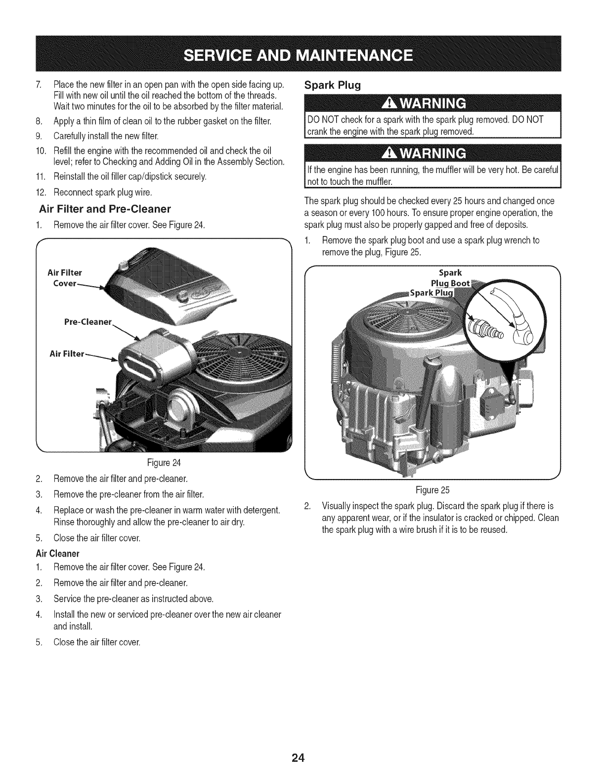
Air Filter and Pre=Cleaner
1. Removethe air filtercover.SeeFigure24.
Figure24
Air Filter
Pre=Cleaner
Air
Spark Plug
DONOTcheckfor a sparkwiththe sparkplugremoved.DONOT
crankthe enginewiththe sparkplugremoved.
Ifthe enginehas beenrunning,the mufflerwill beveryhot. Becardul
notto touchthe muffler.
The sparkplugshouldbecheckedevery25hoursandchangedonce
a seasonor every100hours.Toensureproperengineoperation,the
sparkplugmustalsobe properlygappedandfreeof deposits.
1. Removethe sparkplugboot andusea sparkplugwrenchto
removethe plug,Figure25.
Spark
Pluc
2. Removethe air filterand pre-cleaner.
3. Removethe pre-cleanerfromthe air filter.
4. Replaceor washthe pre-cleanerinwarmwaterwithdetergent.
Rinsethoroughlyandallowthe pre-cleanerto air dry.
5. Closethe airfiltercover.
Air Cleaner
1. Removethe air filtercover.SeeFigure24.
2. Removethe air filterand pre-cleaner.
3. Servicethe pre-cleaneras instructedabove.
4. Installthe newor servicedpre-cleaneroverthe newair cleaner
andinstall.
5. Closethe airfiltercover.
Figure25
2. Visuallyinspectthe sparkplug. Discardthe sparkplugif thereis
any apparentwear,or if the insulatoris crackedor chipped.Clean
the sparkplugwitha wire brushif it is to be reused.
24

3. Measurethe pluggapwitha feelergauge.Correctas necessary To Drain the Fuel:
by bendingthe side electrode,Figure26. Thegapshouldbe set 1. Locatethe fuel filter,whichis routedonthe right sideof the
to .02-.03inches(0.60-0.80ram). enginebetweenthe fueltankandthe engine.SeeFigure27.
Electrode
.030 in.
(0.76 ram)
Clamps_
Figure26
4. Checkthatthe sparkplugwasheris ingoodconditionandthread
the sparkplugin by handto preventcross-threading.
5. Afterthesparkplugis seated,tightenwitha sparkplugwrenchto
compressthe washer.
NOTE:Wheninstallinga newsparkplug,tighten1/2-turnafterthe spark
plugseatstocompressthewasher.Whenreinstallinga usedsparkplug,
tighten1/8-to 1/4-turnafterthe sparkplugseatsto compressthewasher.
The sparkplugmustbetightenedsecurely.A loosesparkplugcan
becomevery hotandcan damagethe engine.
Fuel Filter
Gasolineanditsvaporsareextremelyflammableandexplosive.Fire
or explosioncan causesevereburnsor death.
• Keepgasolineawayfromsparks,openflames,pilotlights,heat,
andotherignitionsources.
• Checkfuellines,tank,cap,andfittingsfrequentlyfor cracks
orleaks.Replaceif necessary.Seea Searsorother qualified
servicedealerto replacefuel line.
• Beforereplacingthe fuel filter,drainthe fueltankor closethe fuel
shut-offvalve.
•Replacementpartsmustbethe sameandinstalledinthe same
positionas the originalparts.
• If fuelspills,waituntil it evaporatesbeforestartingengine.
Figure27
2. Pinchthe in-lineclamponthe fuel filterwitha pairof pliers.
3. Slidethe clampup thefuel line.
4. Pullthe fuel linefreefromthe filterandplacethe openendof the
lineintoanapprovedcontainerto drainthe fuel.
To Replacethe Fuel Filter:
1. Beforereplacingthefuelfilter,drainthefueltankorclosethefuelshut-
offvalve.Otherwise,fuelcanleakoutandcauseafireorexplosion.
2. Usepliersto squeezetabson the clamps,thenslidethe clamps
awayfromthe fuelfilter.Twistandpull the fuel linesoffof thefuel
filter.Referto Figure26.
3. Checkthe fuel linesforcracksor leaks.Replaceif necessary.
4. Replacethefuel filterwithanoriginalequipmentreplacementfilter.
5. Securethe fuellineswiththe clamps.
HYDROSTATIC TRANSMISSION
The zeroturn ridingmoweris equippedwithdualintegratedhydrostatic
pumps/transaxlesthatare sealedandare maintenance-free.Fluid
levelscannotbecheckedandfluidcannotbeaddedorchanged.
TIRE MAINTENANCE
Checkthe tire airpressureafterevery50 hoursof operationorweekly.
Keepthetires inflatedto the recommendedpressures.Improperinfla-
tion will shortenthe tireservicelife.Seethe tire sidewallfor proper
inflationpressures.Observethe followingguidelines:
• Donot inflatea tire abovethe maximumpressureshownon the
sidewallof the tire.
•Donot reinflatea tire thathas beenrunflator seriouslyunder
inflated.Haveaqualifiedtire mechanicinspectandservicethe
tire.
25

LUBRiCATiON
Usinga pressurelubricatinggun, lubricatethe frontcastorwheel
axlesandthe frontpivotaxlewith No.2 multipurposelithium
greaseafterevery10hoursof service.
Periodicallylubricateall otherpivotpointswitha qualitylubricat-
ingoil.
GENERAL BATTERY iNFORMATiON
Shouldbatteryacidaccidentallysplatterinto theeyesor ontothe
skin, rinsethe affectedareaimmediatelywithcleancold water.If
thereis any furtherdiscomfort,seekpromptmedicalattention.If acid
spillsonclothing,first diluteit withcleanwater,then neutralizewitha
solutionof ammonia/wateror bakingsoda/water.
NEVERconnect(ordisconnect)batterychargerclipstothebatterywhile
thechargeris turnedon,asitcancausesparks.Keepallsourcesofignition
(cigarettes,matches,lighters)awayfromthebattery.Thegasgenerated
duringchargingcanbecombustible.Asafurtherprecaution,onlycharge
thebatteryina wellventilatedarea.Alwaysshieldeyesandprotectskin
_andcothngwhenworkngnearbatteres.
Batteriescontainsulfuricacidandmayemitexplosivegases.Useextreme
cautionwhenhandlingbatteries.Keepbatteriesoutofthereachofchildren.
Battery Maintenance
The batteryis filled withbatteryacid andthensealedat the factory.
However,evena "maintenancefree" batteryrequiressomemainte-
nanceto ensureits properlife cycle.
Spraytheterminalsandexposedwire witha batteryterminalsealer,
orcoatthe terminalswith a thincoatof greaseorpetroleumjelly,to
protectagainstcorrosion.
Alwayskeepthe batterycablesandterminalscleanandfreeof
corrosion.
Avoidtipping.Evena sealedbatterywill leak electrolytewhentipped.
BATTERY REMOVAL
leadcompounds.Washhandsafterhandling.
The batteryis locatedonthe right/rearof the ridingmowerbeneaththe
seatbox frame.To removethe battery:
1. Removethe twohextappingscrewsfromthebatteryhold-down
bracketand removethe bracket.Usecareto avoidlosingthe trim
stripfromthe bottomof thebracket.SeeFigure28.
f
Battery Hold Down Bracket
Hex Tap Screw
Figure28
2. Removethe hexcap screwandseresnut securingthe black
negativebatteryleadto the negativebatterypost(markedMEG).
Movethecable awayfromthe negativebatterypost.
3. Removethe hexcap screwandseresnut securingthe redposi-
tive batteryleadto the positivebatterypost(markedPOS).
4. Carefullylift the batteryout of the ridingmower.
5. Installthe batteryby repeatingthe abovestepsinthe reverse
order.
Alwaysconnectthe positiveleadto the batterybeforeconnectingthe
negativelead.Thiswill preventsparkingor possibleinjuryfroman
electricalshortcausedbycontactingthe ridingmowerbodywithtoolsI
I bengusedto connectthe cab es. j
26
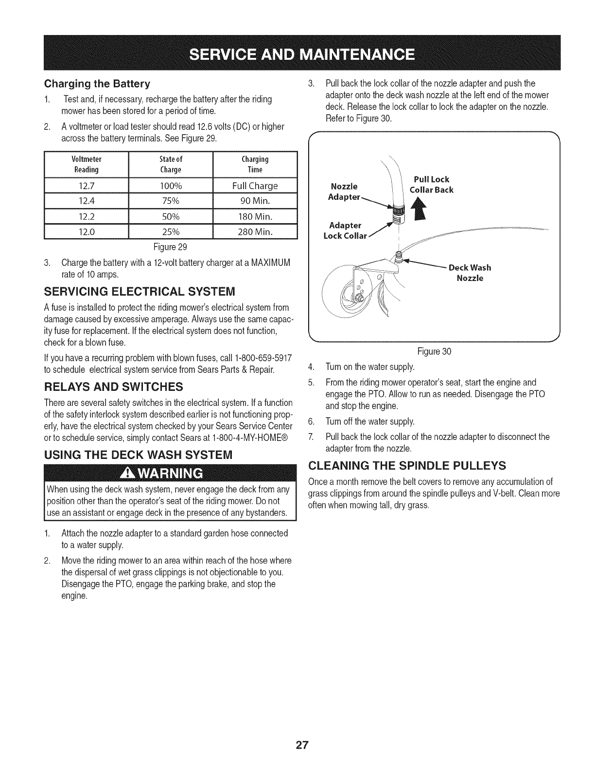
Charging the Battery
1, Testand,if necessary,rechargethebatteryafterthe riding
mowerhasbeenstoredfor a periodof time.
2. A voltmeterorloadtestershouldread12.6volts(DC)or higher
acrossthebatteryterminals,SeeFigure29,
Voltmeter Stateof Charging
Reading Charge Time
12.7 100% Full Charge
12.4 75% 90 Min.
12.2 50% 180 Min.
12.0 25% 280 Min.
Figure29
3. Chargethe batterywitha 12-voltbatterychargerat a MAXIMUM
rateof 10amps.
SERViCiNG ELECTRICAL SYSTEM
A fuseisinstalledto protectthe ridingmower'selectricalsystemfrom
damagecausedby excessiveamperage,Alwaysusethe samecapac-
ityfusefor replacement.Ifthe electricalsystemdoes notfunction,
checkfor a blownfuse.
If youhavea recurringproblemwithblownfuses,call 1-800-659-5917
to schedule electricalsystemservicefromSearsParts& Repair.
RELAYS AND SWITCHES
Thereareseveralsafetyswitchesinthe electricalsystem.Ifa function
of the safetyinterlocksystemdescribedearlieris not functioningprop-
erly,havethe electricalsystemcheckedby your SearsServiceCenter
orto scheduleservice,simplycontactSearsat 1-800-4-MY-HOME®
USING THE DECK WASH SYSTEM
Whenusingthe deckwashsystem,neverengagethe deckfromany
positionotherthanthe operator'sseatof the ridingmower.Do not
usean assistantorengagedeckin the presenceof any bystanders.
Pullbackthe lock collarof the nozzleadapterandpushthe
adapterontothedeckwashnozzleat the leftendof the mower
deck. Releasethe lockcollarto lockthe adapteron the nozzle.
Referto Figure30.
Deck Wash
Nozzle
Figure30
4. Turnonthe watersupply.
5. Fromthe ridingmoweroperator'sseat,startthe engineand
engagethe PTO.Allowto runas needed.Disengagethe PTO
and stopthe engine.
6. Turnoffthe watersupply.
7. Pullbackthe lockcollarof the nozzleadapterto disconnectthe
adapterfromthe nozzle.
CLEANING THE SPINDLE PULLEYS
Oncea monthremovethe beltcoversto removeany accumulationof
grassclippingsfromaroundthe spindlepulleysandV-belt.Cleanmore
oftenwhenmowingtall,dry grass.
,
Attachthe nozzleadapterto a standardgardenhoseconnected
to a watersupply.
Movethe ridingmowerto an areawithinreachof the hosewhere
the dispersalof wetgrassclippingsis notobjectionableto you.
Disengagethe PTO,engagethe parkingbrake,andstopthe
engine.
27

USING THE TRANSMiSSiON BYPASS RODS
Iffor any reasonthe ridingmowerwillnot driveor youwishto movethe
ridingmower,the twohydrostatictransmissionsareequippedwitha
bypassrodthatwill allowyou to manuallymovethe ridingmowershort
distances.
Do nottowthe ridingmower,evenwiththe bypassrodengaged.
Serioustransmissiondamagewill resultfromdoingso.
1. Fromjustin frontof thetwo reartires,locatethe transmission
bypassrods.Referto Figure31.
RH Transmission
Bypass Rod
PullOut Bypass
RodThenLower
into Slot
Keyhole Slot
forwardor rearwardwithinthe rangeof the slotin eachcontrollever
mountingbracket.
Toadjustthedrive controlleverheight,proceedas follows:
1. Removethe flangelocknut,flatwasher,andhexscrewsecuring
the leverto the pivotbracket.
2. Whilesupportingthecontrolleverto keepitfromfalling,remove
the hex insertflangelocknut andshoulderscrewfromthe bottom
of the controlleverandpivotbracket.Referto Figure32.
Fiat Washer
Pivot Bracket
Flange
Nut
Figure31
2. Pullonerodtowardthe frontof the ridingmoweruntilthe flange
onthe rod isforwardof the keyholeslotintheframeassembly.
3. Lowerthe bypassrodintothe keyholeslotandreleaseso the rod
flangeis againstthe frontof the framebracket.
4. Repeattheaboveproceduretoengagethe otherbypassrodon
theother sideof the ridingmower.
5. Aftermovingthe ridingmower,disengageboth bypassrods.Lift
the rodandguidethe flangeof the rod backthroughthe larger
circularopeningof the keyhole,then releasethe rod.
NOTE:Theridingmowerwillnotdrivewiththebypassrodsintheengage
position.
ADJUSTMENTS
Shutthe engineoff, removethe ignitionkeyand engagethe parking
brakebeforemakingadjustments.Protectyour handsbyusing heavy
[g oveswhenhand ngthe bades.
Adjusting RH & LH Drive Control Levers
The RHand LHdrivecontrolleverscanbe adjustedup ordownand
fore-and-aftfor the comfortof the operator.The drivecontrollevers
can beplacedineitherof two heightpositions,and/orcan be moved
3. Repositionthe controlleverto alignwith theother setof holesin
the pivotbracketandinsertthe shoulderscrewremovedearlier.
Fastenwiththe hexinsertflangelock nutandtightenuntilsnug.
4. Insertthe hex screwwithwasherthroughthe controlleverslot
andthe pivotbracket.Threadtheflange locknutontothe screw,
but do nottightennow.
5. Ifyou aregoingto adjustthecontrolleversforwardor rearward,
proceedtothe nextstep.Ifnot,fullytightenthe flangelocknut.
Toadjustthedrivecontrolleversforwardor rearward,proceedasfollows:
1. Ifnot alreadyloose,loosenthe flangelocknut androtatethe
controllevereitherforwardor rearwardto thedesiredposition.
See Figure31.
NOTE:Ifthecontrolleveristootightto move,slightlyloosenthehexinsert
flangelocknutandshoulderscrewatthebottomof thecontrollever.
2. Tightenthe flangelocknut to fixthe controlleverintheadjusted
position
3. Repeatthe aboveprocedureto adjustthe othercontrolleverinto
the sameposition.Adjustso thatbothleversare evenwitheach
otherwhen inthe neutralposition.
28
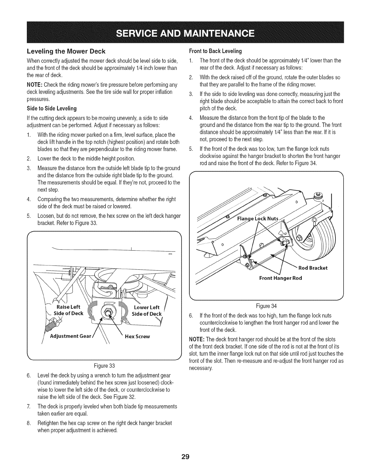
Leveling the Mower Deck
Whencorrectlyadjustedthe mowerdeck shouldbelevel sideto side,
andthe frontof the deckshouldbeapproximately1/4inchlowerthan
the rearof deck.
NOTE:Checkthe ridingmower'stire pressurebeforeperformingany
decklevelingadjustments.Seethetire side wallfor properinflation
pressures.
Side to Side Leveling
If thecuttingdeckappearsto bemowingunevenly,a sideto side
adjustmentcan be performed.Adjustif necessaryas follows:
1. Withthe ridingmowerparkedon a firm,levelsurface,placethe
decklift handleinthe top notch(highestposition)androtateboth
bladessothattheyare perpendicularto the ridingmowerframe.
2. Lowerthe deckto the middleheightposition.
3. Measurethe distancefromthe outsideleftbladetip to the ground
andthe distancefromthe outsiderightbladetip tothe ground.
Themeasurementsshouldbeequal.If they'renot,proceedto the
nextstep.
4. Comparingthetwo measurements,determinewhetherthe right
sideof the deckmust beraisedorlowered.
.Loosen,butdo not remove,the hexscrewonthe leftdeckhanger
bracket.Referto Figure33.
!
o
Figure33
6. Levelthe deckby usinga wrenchto turnthe adjustmentgear
(foundimmediatelybehindthe hex screwjustloosened)clock-
wiseto lowertheleft sideof the deck,or counterclockwiseto
raisethe leftside of the deck.SeeFigure32.
7. Thedeckis properlyleveledwhenbothbladetip measurements
takenearlierareequal.
8. Retightenthe hex capscrewonthe rightdeckhangerbracket
whenproperadjustmentis achieved.
Front to Back Leveling
1. The frontof thedeck shouldbeapproximately1/4"lowerthan the
rearof the deck.Adjustif necessaryas follows:
2. Withthe deckraisedoffof the ground,rotatetheouterbladesso
thattheyareparallelto the frameof the ridingmower.
3. Ifthe sideto sidelevelingwasdonecorrectly,measuringjustthe
rightbladeshouldbeacceptableto attainthe correctbackto front
pitchof the deck.
4. Measurethedistancefromthe fronttip of the bladeto the
groundandthe distancefromthe reartip to the ground.Thefront
distanceshouldbe approximately1/4"lessthanthe rear.If itis
not,proceedto the nextstep.
5. Ifthe frontof thedeckwastoo low,turn the flangelocknuts
clockwiseagainstthe hangerbracketto shortenthe fronthanger
rodand raisethe frontof the deck. Referto Figure34.
Bracket
Front Hanger Rod
Figure34
Ifthe frontof thedeckwastoo high,turn theflangelock nuts
counterclockwiseto lengthenthe fronthangerrodandlowerthe
frontof the deck.
NOTE:Thedeckfronthangerrodshouldbeat the frontof the slots
of the frontdeckbracket.Ifoneside of the rodisnot at the frontof its
slot,turnthe innerflange locknuton thatside untilrodjusttouchesthe
frontof the slot.Then re-measureand re-adjustthefronthangerrodas
necessary.
29
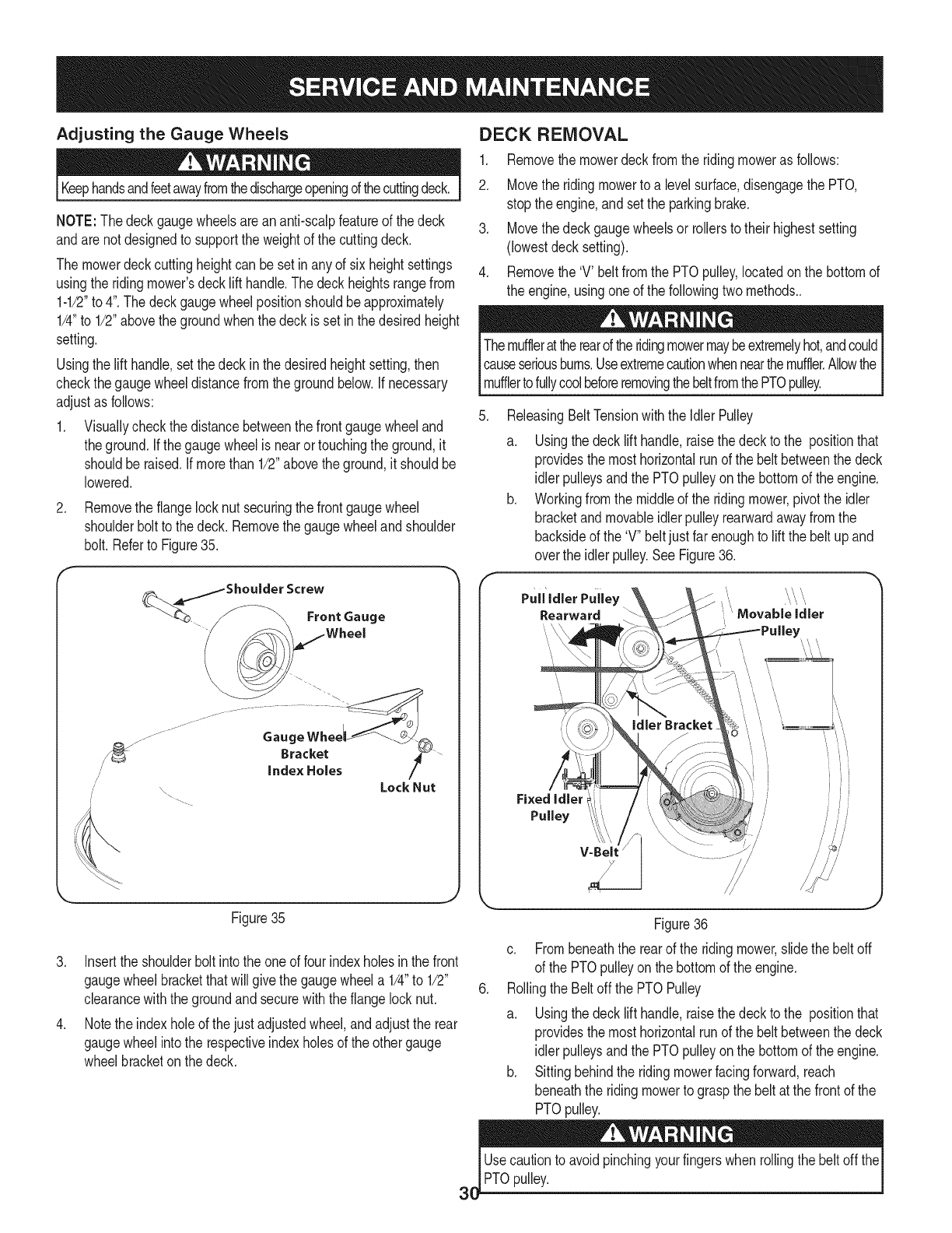
Adjusting the Gauge Wheels
Keephandsandfeetawayfromthedischargeopeningofthecuttingdeck.
NOTE:The deckgaugewheelsareananti-scalpfeatureof the deck
andare not designedto supportthe weightof the cuttingdeck.
The mowerdeckcuttingheightcan besetinanyof six heightsettings
usingthe ridingmower'sdecklift handle.Thedeckheightsrangefrom
1-1/2"to 4".The deckgaugewheelpositionshouldbe approximately
1/4"to 1/2"abovethegroundwhenthe deckisset inthe desiredheight
setting.
Usingthe lift handle,setthe deckinthe desiredheightsetting,then
checkthegaugewheeldistancefromthegroundbelow.Ifnecessary
adjustas follows:
1. Visuallycheckthe distancebetweenthe frontgaugewheeland
theground.If thegaugewheelisnearortouchingthe ground,it
shouldberaised. Ifmorethan 1/2"abovethe ground,itshouldbe
lowered.
.Removethe flangelocknut securingthefrontgaugewheel
shoulderboltto thedeck. Removethe gaugewheelandshoulder
bolt.Referto Figure35.
ulder Screw
....._ Front Gauge
/
//'
Gaug
Bracket
index Holes Lock Nut
Figure35
3. Insertthe shoulderbolt intothe oneof fourindexholesin the front
gaugewheelbracketthatwill givethe gaugewheela 1/4"to 1/2"
clearancewiththe groundandsecurewiththe flangelocknut.
4. Notethe indexholeof the justadjustedwheel,andadjustthe rear
gaugewheelintothe respectiveindexholesof the othergauge
wheelbracketonthe deck.
DECK REMOVAL
1. Removethe mowerdeckfromthe ridingmoweras follows:
2. Movethe ridingmowerto a levelsurface,disengagethe PTO,
stopthe engine,andsetthe parkingbrake.
3. Movethedeckgaugewheelsor rollersto their highestsetting
(lowestdecksetting).
4. Removethe 'V' beltfromthe PTOpulley,locatedonthe bottomof
the engine,usingoneof the followingtwomethods..
Themufflerattherearoftheridingmowermaybeextremelyhot,andcould
causeseriousburns.Useextremecautionwhennearthemuffler.Allowthe I
I muffertofu y coo beforeremovngthebetfromthePTOpu ey. j
.ReleasingBeltTensionwiththe Idler Pulley
a. Usingthedeck lifthandle,raisethedeckto the positionthat
providesthe mosthorizontalrunof the belt betweenthe deck
idlerpulleysandthe PTOpulleyonthe bottomof theengine.
b. Workingfromthe middleof the ridingmower,pivotthe idler
bracketand movableidlerpulleyrearwardawayfromthe
backsideof the 'V" beltjustfar enoughto liftthe belt upand
overthe idlerpulley.SeeFigure36.
Pull'idler Puiley ""
Rearward Movable idler
V-Beit
.
Figure36
c. Frombeneaththe rearof the ridingmower,slidethe beltoff
of the PTOpulleyonthe bottomof the engine.
Rollingthe Beltoff the PTOPulley
a. Usingthedeck lifthandle,raisethedeckto the positionthat
providesthe mosthorizontalrunof the belt betweenthe deck
idlerpulleysandthe PTOpulleyonthe bottomof theengine.
b. Sittingbehindthe ridingmowerfacingforward,reach
beneaththe ridingmowerto graspthe beltat the frontof the
PTOpulley.
Usecautionto avoidpinchingyourfingerswhenrollingthe beltoff the
PTOpulley.

c. Pulltheleftsideofthebeltrearwardanddownwardwhile
manuallyturningthePTOpulleytotherightuntilthebelt
ridesoutontotheedgeofthelowersheaveofthepulley.
NOTE:Ifpullingtherightsideofthebelt,turnthepulleytotheleft.
d. Whilestillholdingthebeltdownward,continueturningthe
PTOpulleyuntilthebeltisrolledoffthepulley.Referto
Figure37.
f
PTO Belt
\
.
6.
Transmission
Tube
Figure37
Lowerthe deckto the groundusingthe decklift handle.
Locatethe LHand RHdeck supportpinsoneach sideof the
deck.Pullthe decksupportpinsoutwardandlockin the disen-
gagedpositionto releasethe deckfromthe ridingmower'sLH
andRH decklift arms.Referto Figure38.
--- Rear Deck Deck Lift Arm
Hanger Bracket
/
/
J
\\\\
Deck \\
Support \\ RearHanger
Pin Bracket Slot
Figure38
7. Raisethe decklift armsout of the rearhangerbracketslotsby
raisingthedecklift handleon the ridingmowerto its highest
position.Referto Figure36.
31
8. Slidethe deckforwardsothatthe deckfronthangerrodcan be
liftedout of the twoslotsof the frontdeck bracket.Afterliftingthe
fronthangerrodout of the slots,slidethedeck rearwardsothat
the rodcan no longerengagethe slots.
9. Usingcareto preventthe fronthangerrodfromfallingbackinto
the deckbracketslots,carefullyslidethe cuttingdeck(fromthe
rightside)out fromunderneaththe ridingmower.
DECK INSTALLATION
To installthe mowerdeck, proceedas follows:
1. Whileholdingthe deckfronthangerrodupward,carefullyslide
the deckunderneaththe rightside of the ridingmower.
2. Whilestill holdingthefronthangerrod,slidethe deckforwarduntil
the fronthangerrodcan beloweredinto the slotsof the frontdeck
bracket.
3. Lowerthefronthangerrodintothe slotsof the frontdeckbracket,
then slidethe deckrearward.
4. Maneuverthe deckso thatthe slotsinthe two reardeckhanger
bracketsapproximatelyalignwiththe deckliftarmsof the riding
mower.Referto Figure38.
5. Usethe ridingmowerdecklift handleto lowerthe deckliftarms
intothe slotsof the reardeckhangerbrackets.
6. Pullthe decksupportpins outwardand maneuverthe deckas
necessaryto alignthe holesin the deckliftarmswiththe pins.
Referto Figure38.
7. Whenaligned,pusheachpinfullyinwardthroughthe liftarmsto
securethe armsinthe rearhangerbracketslots.
8. Makecertainthe'V' beltis inthespindlepulleysonthe deck;then
routethebelt rearwardbeneaththeridingmowerframe,abovethe
transmissiontube(s),to the PTOpulleyonthe bottomof theengine.
9. Installthe 'V' beltonto the PTOpulleyusingoneof the following
two methods.
The mufflerat the rearof the ridingmowermaybe extremelyhot,
andcouldcauseseriousburns.Useextremecautionwhennearthe
_muffer. A ow the mufferto fu y coo before nsta ngthe bet.
10. Usingthe IdlerPulleyto Tensionthe Belt.
a. Usingthedecklift handle,raisethe deckto the positionthat
providesthe mosthorizontalrunof the belt betweenthe deck
idlerpulleysandthe PTOpulleyonthe bottomof theengine.
b. Installthe belt inthe PTOpulleyonthe bottomof theengine.
c. Routethebacksideof the belt aroundthefixedidlerpulleyof
the deck. Referto Figure36.
d. Workingfromthe middleof the ridingmower,pivotthe idler
bracket/movablepulleyrearwardagainstthe springtension
and slidethe backsidedthe beltontothe movableidler
pulley.Referto Figure36.
11. Rollingthe Beltinto the PTOPulley.
a. Usingthedecklift handle,raisethe deckto the positionthat
providesthe mosthorizontalrunof the belt betweenthe deck
idlerpulleysandthe PTOpulleyonthe bottomof theengine.

b. Makecertainthebeltisinthespindlepulleysofthedeck,
andthatthebacksideofthebeltisagainstboththefixedand
movableidlerpulleys.RefertoFigure34.
c. Sittingbehindtheridingmower,facingforward,makecertain
thebeltisnottwisted;thenreachbeneaththeridingmower
tograspthebeltandpullittowardthePTOpulley.
Usecautiontoavoidpinchingyourfingerswhenrollingthebeltoffthe
PTOpulley.
d. Pulltherightsideofthebeltrearwardandplacethenarrow
VsideofthebeltintothePTOpulley.SeeFigure36.
e. Whileholdingthebeltandpulleytogether,rotatethepulley
totheleft(SeeFigure35).Continueholdingandrotatingthe
pulleyandbeltuntilthebeltisfullyrolledintothePTOpulley.
REPLACING THE DECK DRIVE BELT
1. Removethe deckfrombeneaththe ridingmower,(referto Deck
Removalon page30).
2. Removethehexwasherscrewssecuringthebeltcoverstothedeck
andremovethebeltfromthespindlepulleys.Referto Figure39.
Belt Cover_
Screw
.
.
Figure39
Installthe newbeltaroundthe spindlepulleysas shownin Figure
39and reinstallthe belt covers.
Routethe belt rearwardbetweenthe twoidlerpulleysandreinstall
thedeckfollowingthe instructionsin DeckInstallation.
Mower Blade Care
Beforeperforminganymaintenance,placethe PTOswitchin the"OFF"
position,engagetheparkingbrakelever,turntheignitionkeyto the
"OFF"positionandremovethe keyfromtheswitch.Protectyourhands
byusingheavygloveswhenhandlingthe blades.Whenservicingthe
mowerdeck,becarefulnotto cutyourselfonthe sharpenedblades.
The cuttingbladesmustbekeptsharpat all times.Sharpenthe cutting
edgesof the bladesevenlyso thatthe bladesremainbalancedandthe
sameangleof sharpnessis maintained.
Ifthe cuttingedgeof a bladehas alreadybeensharpenedmany
times,or if anymetalseparationis present,it is recommendedthat
new bladesbe installed.Newbladesareavailableat yourauthorized
dealer.
The
1.
.
bladesmaybe removedas follows.
Removethe deckfrombeneaththe ridingmower,(referto Deck
Removalon page30) thengentlyflip the deckoverto exposeits
underside.
Usea 15/16"wrenchto holdthe hexnut ontop of the spindle
assemblywhenlooseningthe hex nutsecuringthe blade.A block
of wood maybe placedbetweenthe deckhousingandthecutting
edgeof the bladeto helpinbreakingloosethe hex nutsecuring
the blade.SeeFigure40.
Spindle Assembly
Figure40
3. When reinstallingthe blades,besuretheyare installedso thatthe
wind wingsarepointingupwardtowardthe top of deck.
4. Tightenthe bladenutsto 70-90ft. Ibs.
5. Reinstallthe deck(referto DeckInstallationonpage31).
32

TRANSMiSSiON DRIVE BELT
Severalcomponentsmust beremovedandspecialtoolsusedin
orderto changethe ridingmower'stransmissiondrivebelt.Seeyour
SearsServiceCenterorto scheduleservice,simplycontactSearsat
1-800-4-MY-HOME®.
RIDING MOWER CREEPING
Creepingis the slightforwardor backwardmovementof the riding
mowerwhentheengineis runningat highidleandthe drivecontrol
leversareopenedout inthe neutralposition.
If afteroperatingthe ridingmowerfor sometime,it beginsto creep
whilein the neutralposition,adjustthe transmissioncontrolrodsas
follows.
1. Placethefrontof the ridingmoweragainstan immovableobject
(e.g.wall,post,etc.).
2. Jackup the rearof the ridingmowersothat bothrearwheelsare
approximatelyoneinch of the ground.
3. Withtheenginerunningat highidleandthedrive control
leversopenedout inthe neutralposition,andthe parkingbrake
disengaged,checkthe rearwheelsfor rotation.
4. If onlyonewheelis rotating,locatethetransmissioncontrolrod
beneaththe frameat the frontof the reartire. Ifbothwheels
rotate,locatebothcontrolrods.SeeFigure41.
RH Transmission
Flange
Lock Nut
J
Transmission
Arm
Figure41
5. Removetheflangelocknut andhex screwsecuringthe transmis-
sioncontrolrodto thetransmissioncontrolarm.Wheelrotation
shouldstop.Ifit doesnot,contactyourCub CadetServiceDealer.
6. If the rotationstops,adjustthe controlrodupor downas
necessaryto alignwiththe holeinthe transmissioncontrolarm.
Re-insertthe hexnut intothe holein the controlarmandsecure
withthe hexlocknut.
7. If necessary,repeatthe previoustwostepsto adjustthe other
transmissioncontrolrod.
8. Lowerthe ridingmowerand removethejack.
RIDING MOWER HIGH SPEED TRACKING
1. Ifthe ridingmowertracksto onesidewith bothdrivecontrollevers
fullyforward,adjustthecontrolleversas follows:
2. Checkfor properandbalancedair pressurein bothfrontand rear
tires. Refilltiresif necessary.
3. Performthe firstthree stepsin the previoussub-section,Riding
mowerCreeping,to verifythatthe ridingmoweris not creeping.If
creeping,adjustfollowingthe instructionsinthatsub-section.
4. Recheckthe trackingaftermakinganyadjustmentsto the
transmissioncontrolrods.
5. Ifuneventrackingpersists,notewhichdirectionthe ridingmower
istracking.
6. Ifthe ridingmowertracksto the right,adjustthecontrolleverstop
boltonthe left side.
7. Ifthe ridingmowertracksto the left,adjustthecontrolleverstop
boltonthe rightside.
8. Locatethe applicablestopbolton the leftor rightconsole.See
Figure42.
Jam Nut
Console
Bolt
Figure42
9. Loosenthejam nut onthe stopbolt,thenturn the stopbolt
counterclockwiseto makeit longer.Recheckthe trackingandfine
tune theadjustmentas necessary.
NOTE:Ifthestopboltisadjustedtoofar,thetrackingproblemwillchange
sides.Makefinetuningadjustmentsbyshorteningthesamebolt.
10. Tightenthejam nutagainstthe consoleandrepositionthe control
leveras necessaryto makethetwo controlhandlesevenwith
eachother.
33

Neverstoregardenridingmowerwithfuel in tankindoorsor in poorly
ventilatedareaswherefuel fumesmayreachan openflame,spark,
or pilot lightas ona furnace,waterheater,clothesdryer,or gas
app ance. j
RIDING MOWER STORAGE
If yourridingmoweris notgoingto beoperatedfor anextendedperiod
of time(thirtydaysto approximatelysixmonths),the ridingmower
shouldbepreparedfor storage.Storethe ridingmowerin a dryand
protectedlocation.If storedoutside,coverthe ridingmower(including
the tires)to protectit from the elements.The proceduresoutlined
belowshouldbeperformedwheneverthe ridingmoweris placedin
storage.
1. Changethe engineoiland filterfollowingthe instructionsprovided
in theServiceand Maintenancesectionof thismanual..
Neverstorethe ridingmowerwithfuelin thetank indoorsor inpoorly
ventilatedenclosures,wherefuelfumesmayreachan openflame,
sparkor pilotlight as ona furnace,waterheater,clothesdryer,etc.
.If storingthe ridingmowerfor 30daysormore:
a. Topreventgumdepositsfromforminginsidetheengine's
carburetorandcausingpossiblemalfunctionof the engine,the
fuelsystemmustbeeithercompletelyemptied,orthe gasoline
mustbetreatedwitha stabilizerto preventdeterioration.
9roblems.
b. Usingafuel stabilizer:
• Readthe productmanufacturer'sinstructionsand recom-
mendations.
Addto clean,freshgasolinethe correctamountof
stabilizerforthe capacity(approximately3 gallons)of the
fuel system.
Fillthe fuel tankwithtreatedfueland runthe enginefor
2-3minutesto get stabilizedfuel intothe carburetor.
c. Emptyingthefuel system:
Priorto puttingthe ridingmowerin storage,monitorfuel
consumptionwiththe goalof runningthefuel tankempty.
Startthe engineandallowit to runout of fuel.Thiswill
preventgum andvarnishdepositsfromforming.
3. Removethesparkplugsandpourapproximatelyoneounceof oil
intoeachcylinder.Crankthe engineoneor twoturnsto spread
the oilevenlyonthe cylinderwalls.Replacethe sparkplugs.
4. Cleantheengineand theentire ridingmowerthoroughly.
NOTE: Useof a pressurewasheror gardenhoseis not recommended
to cleanyour ridingmower.Theymaycausedamageto electrical
components,spindles,pulleys,bearingsorthe engine.The useof
waterwill resultin shortenedlife andreduceserviceability.
Sharpenthe bladesso thatthe mowerwill be readyto use when
needed.
6. Protectthe metalsurfaces.Repairscratcheswiththe appropriate
touch-upspraypaint.Brusha rustpreventiveoilonany unpainted
surfacesincludingthe pulleysandblades.(Becarefulnot to get
any oilon thedrive belts.)
7. Cleanandfullychargethe battery,thendisconnectthe negative
cableat thebatteryto preventpossibledischarge.Rechargethe
batteryperiodicallywhenin storage.
NOTE:Removethebatteryif exposedto prolongedperiodsof sub-
freezingtemperatures.Storeina cool,dry locationwheretemperatures
areabovefreezing.
8. Lubricatealllubricationpoints.
9. Jack the mowerup andstoreit onblocksto takethe weightoff of
the tires.
REMOVING THE RIDING MOWER FROM
STORAGE
1. Checkthe engineoil.
2. Fullychargethe battery,lowerridingmoweroff blocks,andinflate
the tiresto the recommendedpressure.
3. Removethe sparkplugsandwipe themoff. Usingthe starter,
crankthe engineto pumpthe excessoil out of the sparkplug
holes.Replacethe sparkplugsandthe ignitionleads.
4. Ifdrainedbeforestoring,fill the fueltankwithclean,fresh
gasoline.
5. Checkthe levelof the engineoil inthe crankcaseandthe
hydraulicreservoirtank.
6. Startthe engineandallowto idlefor a fewminutesto ensure
engineis operatingproperly.
7. Drivethe ridingmowerwithouta loadto makecertainallthe riding
mowersystemsare functioningproperly.
34

Beforeperforminganytypeof maintenance/service,disengageall
controlsandstoptheengine.Waituntilallmovingpartshavecometo
acompletestop.Disconnectsparkplugwireandgrounditagainstthe
I engineto preventunintendedstarting.Alwayswearsafetyglassesduring
loperationorwhileperforminganyadjustmentsor repairs.
Thissectionaddresses minor serviceissues.Tolocate the nearest Sears Service Centeror to scheduleservice,simplycontactSears
1. PTO/BladeEngageknobengaged.
2. Parkingbrakenotengaged.
3. Sparkplugwire disconnected.
.Throttlecontrollevernot incorrect starting
position.
5. Fueltank empty,or stalefuel.
6. Blockedfuel lineorfuel filter.
7. Faultysparkplug.
8. Engineflooded.
9. Fuse(s)blown.
at 1-800-4-MY-HOME®.
Enginefailsto start
Enginerunserratically 1. RidingmowerrunningwithChokeactivated.
1. Placeknobindisengaged(OFF)position.
2. Engageparkingbrake.
3. Connectwireto sparkplug.
2. Sparkplugwiresloose.
3. Blockedfuel lineor stalefuel.
4. Ventingas cap plugged.
5. Wateror dirt in fuel system.
4. PlaceThrottleleverto FASTposition.
5. Filltankwithclean,fresh(lessthan 30daysold)gas.
6. Replacefuel line.Seea Searsorotherqualified
servicedealer.Replacefuelfilter. Seethe Service
6. Dirtyair cleaner.
andMaintenancesection.
7. Clean,adjustgapor replaceplug.
8. Crankenginewiththrottlein FASTposition.
9. Replacefuse.
1. Checkthatthe electricchokeis working.Seea
Searsorotherqualifiedservicedealer.
2. Connectandtightensparkplugwires.
3. Replacefuel line.Seea Searsorotherqualified
servicedealer.Filltankwithclean,freshgasoline
andreplacefuelfilter. Seethe Serviceand Mainte-
nancesection.
4. Clearventor replacecap if damaged.
5. Drainfuel tank. Refillwithclean,freshgasoline.See
the Serviceand Maintenancesection.
6. Cleanor replaceair cleanerpaperelementor clean
foampre-cleaner.
• lili
NEED MORE HELP?
Find this and a[[ your other product manuals online.
Get answers from our team of home experts.
Get a personalized maintenance plan for your home.
Find information and toots to hetp with home projects.
bes_t _eyon f}y Sea_s
35
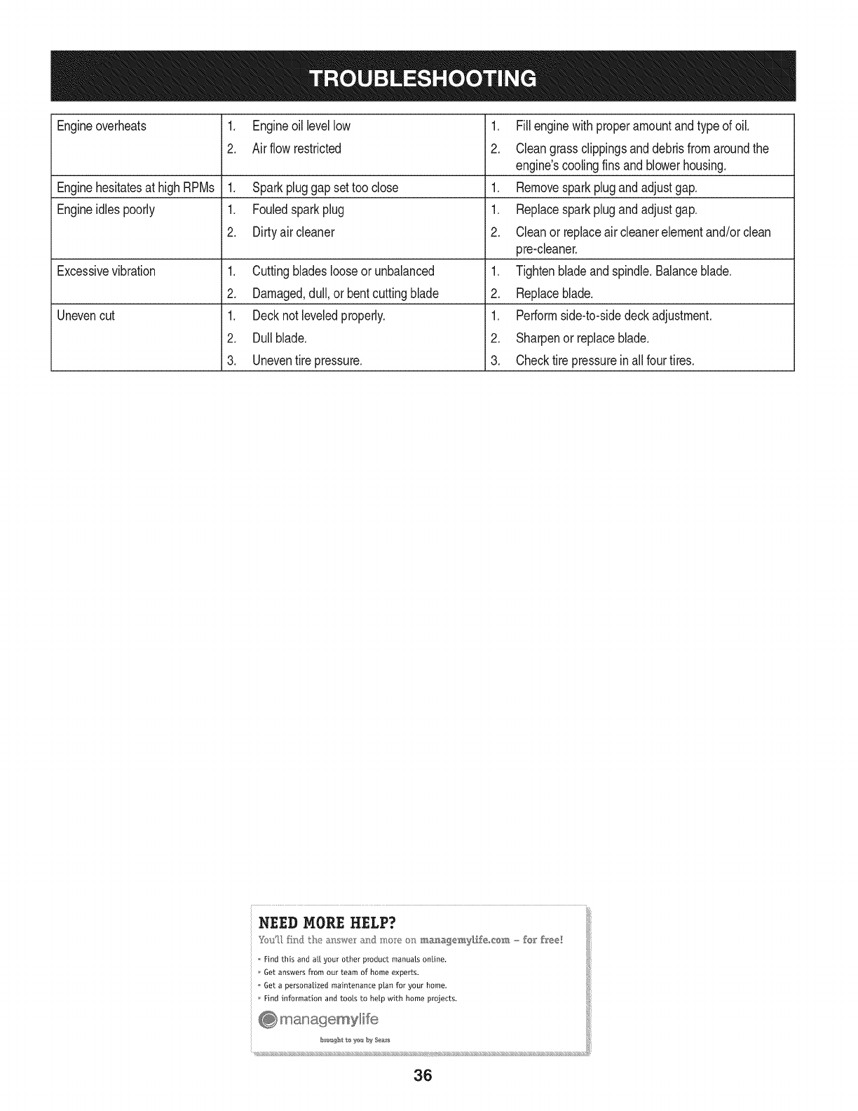
Engineoverheats 1. Engineoillevellow
2. Air flowrestricted
.
2.
Enginehesitatesat highRPMs 1. Sparkpluggap settoo close 1.
Engineidles poorly 1. Fouledsparkplug 1.
2. Dirtyair cleaner 2.
Excessivevibration 1. Cuttingbladeslooseor unbalanced 1.
2. Damaged,dull,or bentcuttingblade 2.
Unevencut 1. Decknot leveledproperly. 1.
2. Dullblade. 2.
3. Uneventire pressure. 3.
Fillenginewith properamountandtype of oil.
Cleangrassclippingsanddebrisfromaroundthe
engine'scoolingfinsandblowerhousing.
Removesparkplugandadjustgap.
Replacesparkplugandadjustgap.
Cleanor replaceair cleanerelementand/orclean
pre-cbaner.
Tightenbladeandspindle.Balanceblade.
Replaceblade.
Performside-to-sidedeckadjustment.
Sharpenor replaceblade.
Checktire pressureinallfour tires.
....... L
NEED MORE HELP?
Find this and a[[ your other product manuals online,
Get answers from our team of home experts.
Get a persona[ized maintenance plan for your home.
Find information and tools to help with home projects,
@ managemylife
bI'_u_htte yes b_4Sea_
_ (((((((((((((((((((((((((((S ((((((((((((((((((((((((
36
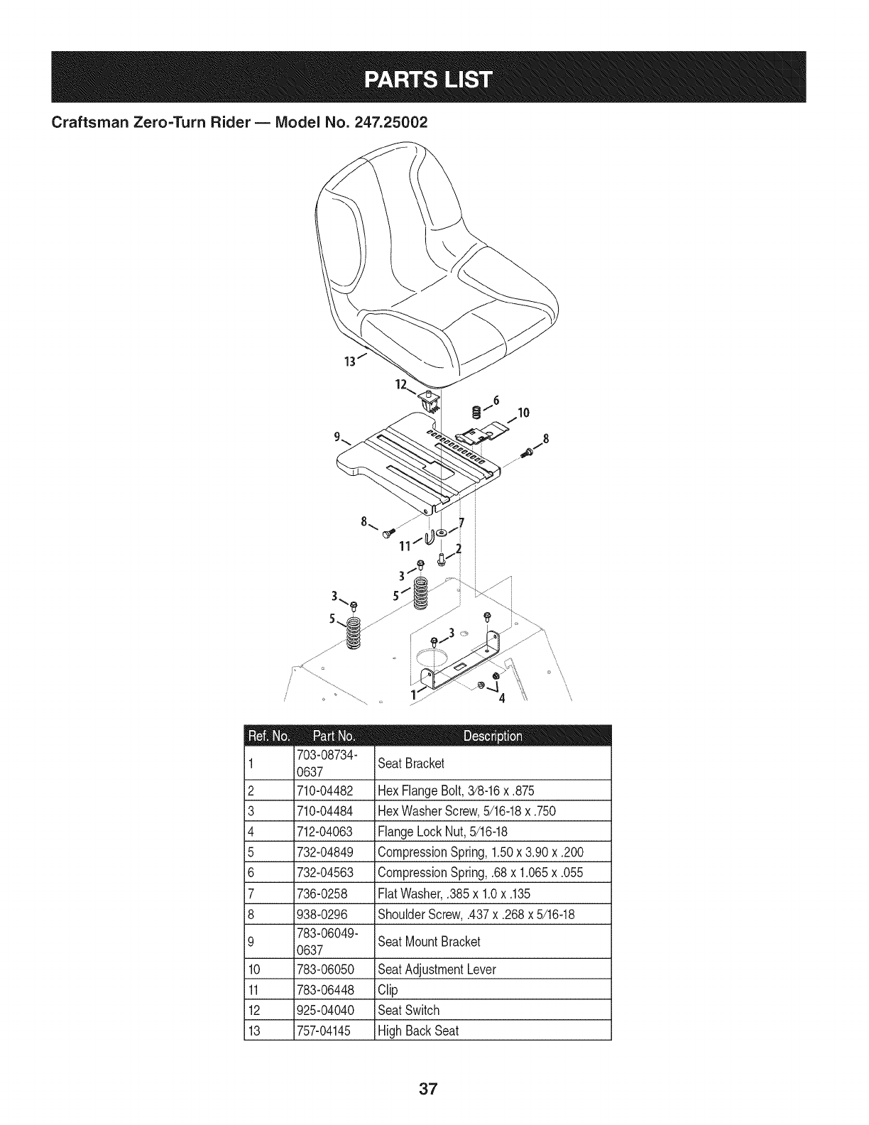
Craftsman Zero=Turn Rider B IViodel No. 247.25002
11
5/
I = 0 O
703-08734-
1 SeatBracket
0637
2 710-04482 HexFlangeBolt,3/8-16x ,875
3 710-04484 HexWasherScrew,5/16-18x ,750
4 712-04063 FlangeLockNut,5/16-18
5 732-04849 CompressionSpring,1,50x 3,90 x ,200
6 732-04563 CompressionSpring,,68x 1,065x .055
7 736-0258 FlatWasher,,385x 1,0x ,135
8 938-0296 ShoulderScrew,,437x .268x 5/16-18
783-06049-
9 SeatMountBracket
0637
10 783-06050 SeatAdjustmentLever
11 783-06448 Clip
12 925-04040 SeatSwitch
13 757-04145 HighBackSeat
37

Craftsman Zero=Turn Rider B Model No. 247.25002
2
3
4
5
6
7
935-0149
735-04081
951-04209B
751-10442
951-12428
751-12118
751-12089
FuelTankBushing
iRubberGrommet
FuelTank
FuelPick-UpFitting
iFuelCap
FuelRolloverValve
VentHose
38

Craftsman Zero=Turn Rider- IViodel No. 247.25002
15..
20\
,\\\
18\
12
1/
39

Craftsman Zero=Turn Rider B Model No. 247.25002
D = 0 0
603-04680A-
1 0637 Frame Assembly
2 703-05829 Drive Idler Arm
3 710-05097 Hex Screw, 3/8-16 x 1.5
4 710-3005 Hex Screw, 3/8-16 x 1.25
5 712-04065 Flange Nut, 3/8-16
6 732-0626 Extension Spring, .75 x 5.06
7 710-0520 Hex Screw, 3/8-16 x 1.5
8 738-04058 Shoulder Spacer, .39 x 1.0 x .7
9 738-04162A Shoulder Spacer, .884 x .19
10 756-04129B Idler Pulley, 4.25 Dia.
11 925-04847C Wire Harness
12 710-0653 Hex Screw, 1/4-20x .375
13 712-0271 Hex Nut, 1/4-20
14 925-04022B Hour Meter
15 925-04165 Neutral Switch
16 925-04174 PTO Switch
17 925-04228 Ignition Switch
18 725-04363 Interlock Switch
19 725-04439 Solenoid
20 925-2054A Key
21 925-1707D Battery
22 738-04237A Shoulder Screw, #10-32 x .500
23 726-0470 Cable Tie
4O

Craftsman Zero=Turn Rider B Model No. 247.25002
18_<_
22
/
/
21
41

Craftsman Zero=Turn Rider B Model No. 247.25002
603-04162 RHExhaustAssembly
2 603-04163 LH ExhaustAssembly
603-04691-
3 0637 FrameAssembly
4 703-05441A MufflerMountBracket
5 710-0227 HexWasherScrew,#8-18x 0.500
6 710-04683 HexWasherScrew,3/8-16x 1.000
7 710-0599 HexWasherScrew,1/4-20x 0.500
8 710-1017 iABScrew,1/4-14x 0.625
9 710-3008 HexScrew,5/16-18x .75
10 710-3217 MachineScrew,#8-32x 0.375
11 712-0142 iHexNut,#8-32
12 712-0271 iSemsNut, 1/4-20
13 712-04063 iFlangeLockNut,5/16-18
14 721-0460 ExhaustGasket
15 726-0197 CableTie
16 726-0205 HoseClamp,.490
17 731-04914 ThrottleControlKnob
18 731-1999 ChokePlug
19 736-0148 LockWasher,3/8
20 746-04539 Throttle/ChokeControlCable
21 751-0616B DualNet Muffler
22 751-10349 iFuelHose,1/4
23 951-10517A iOil Drain
24 751-11053 iMufflerDeflector
25 751-3141-14 iOilDrainExtensionHose
26 756-04376 iPTOPulley
445677-0954-
27 G5 iReplacementEngine
42
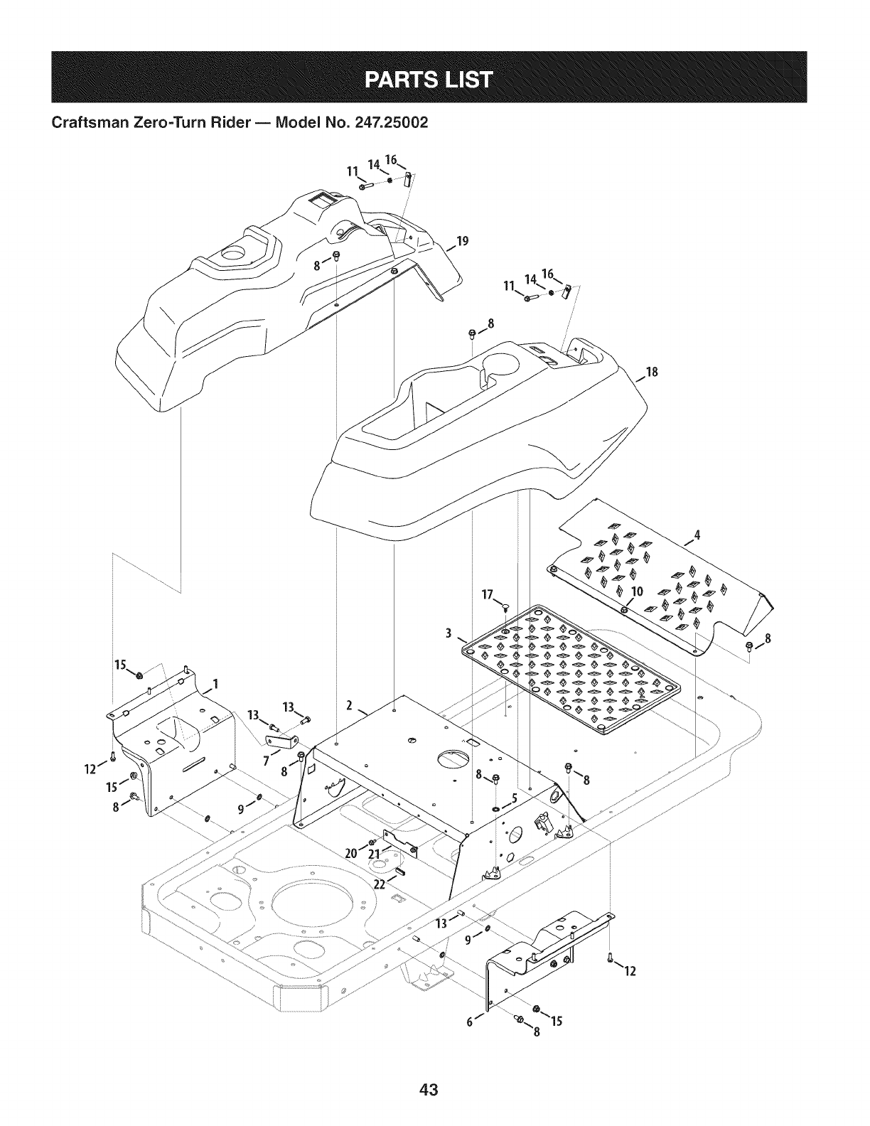
Craftsman Zero=Turn Rider B Model No. 247.25002
19
ii
//
\\
°\15
43
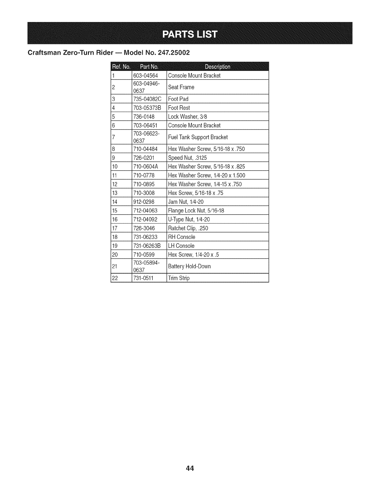
Craftsman Zero=Turn Rider B IViodel No. 247.25002
D = 0 m
603-04564 ConsoleMountBracket
603-04946-
2 SeatFrame
0637
3 735-04082C FootPad
4 703-05373B FootRest
5 736-0148 LockWasher,3/8
6 703-06451 ConsoleMountBracket
703-06623-
7 0637 FuelTankSupportBracket
8 710-04484 HexWasherScrew,5/16-18x .750
9 726-0201 SpeedNut, .3125
10 710-0604A iHexWasherScrew,5/16-18x .825
11 710-0778 HexWasherScrew,1/4-20x 1.500
12 710-0895 HexWasherScrew,1/4-15x .750
13 710-3008 HexScrew,5/16-18x .75
14 912-0298 iJamNut, 1/4-20
15 712-04063 iFlangeLockNut,5/16-18
16 712-04092 iU-TypeNut, 1/4-20
17 726-3046 RatchetClip,.250
18 731-06233 RHConsole
19 731-06263B LH Console
20 710-0599 HexScrew,1/4-20x .5
703-05894-
21 0637 iBatteryHold-Down
22 731-0511 iTrimStrip
44
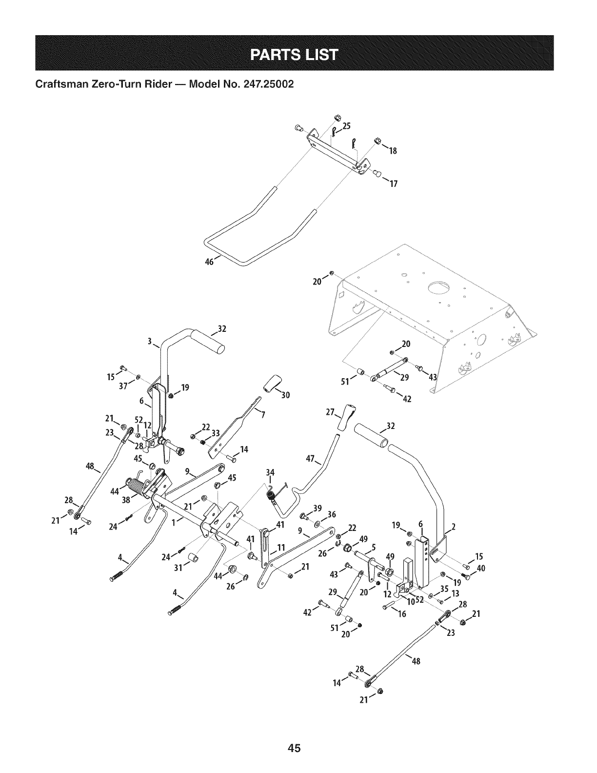
Craftsman Zero=Turn Rider- IViodel No. 247.25002
/
/
/ /
// 17
/
/
20/_- ,'_ ,............................
48
/
/20
/
42
51 20/
45

Craftsman Zero=Turn Rider B IViodel No. 247.25002
D = 0 m
603-04160C-
1 0637 DeckLift ShaftAssembly
603-04322-
2 0637 LapbarLeverRH
603-04324-
3 0637 LapbarLeverLH
4 947-04065 BrakeRod(42"& 50" Decks)
5 647-04099A ControlShaft
6 703-05387B LapbarPivotBracket
703-05396A-
7 BrakeHandle
0637
703-05414A-
8 4044 FrontDeckHangerBracket
703-05793A-
9 DeckLift Arm
4044
10 703-06096A SwitchActuatorBracket
703-06169-
11 Lift LinkPlate
0637
12 710-0347 HexScrew,3/8-16x 1.75
13 710-0433 HexLockScrew,1/4-20x .62
14 710-3005 HexCapScrew,3/8-16x 1.25
15 710-3008 HexCapScrew,5/16-18x .75
16 710-3180 HexCapScrew,5/16-18x 1.75
17 911-0332 ClevisPin,.50x .78
18 712-04243 HexNut, 1/2-13
19 712-04063 HexFlangeinsertLockNut,5/16-18
20 712-04064 HexFlangeInsertLockNut,1/4-20
21 712-04065 HexFlangeinsertLockNut,3/8-16
22 712-0375 HexLockNut,3/8-16
23 912-3001 JamNut,3/8-24
24 914-04023 Bow-TieCotterPin
914-04023
26 716-0106
27 720-0311
28 723-04080
29 727-04141
30 731-04735
31 731-05732
32 720-0274
33 932-0334
34 732-04869A
35 736-0270
36 936-0272
37 936-0275
38 732-04420
39 738-0143
40 938-0296
41 938-0507B
42 938-0572
43 938-0974
44 941-0225
45 741-3074
46 747-04401A
47 747-04637
48 747-05057
49 948-0227A
50 748-04169A
51 750-04676
52 750-04776
D = O O
Cotter Pin
E-Ring,.625 Dia.
HandleGrip
RodEnd
DamperCylinder
HandleGrip
Spacer,.62x 1.0
HandGrip
CompressionSpring
TorsionSpring
BellWasher,.265x .75x.062
FlatWasher,.51x 1.0x .06
FiatWasher,.344x.688x.065
TorsionSprg.,LH (50"&54" Decks)
ShoulderScrew,.498x .340x 3/8-16
ShoulderScrew,.437x .268x 5/16-18
ShoulderScrew,.5 x .434x 3/8-16
ShoulderScrew,.374x 1.16x 1/4-20
ShoulderScrew,.375x.38x 1/4-20
HexFlangeBearing
FlangeBearing,.626x.938x.344
DeckFrontHangerRod
DeckLiftHandleRod
LapbarControlRod
HexFlangeBearing
ControlHub
Spacer,.385x .630x .75
Spacer,.380x .625x .265
46

Craftsman Zero=Turn Rider B IViodel No. 247.25002
47

Craftsman Zero=TurnRider B Model No.247.25002
918-04317
2 918-04431B
3 918-04432B
4 634-04128
5 710-0176
6 710-0395
7 710-3119
8 712-04063
9 712-0459
10 712-3050
11 714-04040
12 936-0227
13 738-04192B
747-04217C-
14 0637
15 750-04561
D = O
WheelHub,7/16-14x 1.6
TransmissionAssembly,LH
TransmissionAssembly,RH
WheelAssembly,18x 9.5-8
iHexCapScrew,5/16-18x 2.75
iHexCapScrew,5/16-18x 2.25
iHexCapScrew,3/8-16x .75
iHexFlangeNut,5/16-18
iHexFlangeNut,7/16-20
iLugNut,7/16-14
Bow-TieCotterPin
FlatWasher,.39x 1.5
iRod,.405x 14
BypassRod
iTube,.45x .69x 10.2
16 954-04043B V-Belt
48

Craftsman Zero=Turn Rider B Model No. 247.25002
_/51
i2o.
25
16
14
49

Craftsman Zero=Turn Rider B Model No. 247.25002
903-04328B-
1 4044 DeckHousing
2 918-04125B SpindleAssembly
3 631-04070A DischargeChuteAssembly
683-0254B-
4 4044 DeckHangerBracket
703-05825C-
5 IdlerArm
4044
703-3279-
6 4044 StopBracket
703-3511A-
7 0637 FingerGuard
8 710-0347 HexCapScrew,3/8-16x 1.75
9 710-0528 HexCapScrew,5/16-18x 1.25
10 710-0599 HexWasherHeadScrew,1/4-20x .5
11 710-04484 HexWasherHeadScrew,5/16-18x .750
783-04415-
12 RHSkirt
4044
13 710-3005 HexCapScrew,3/8-16x 1.25
14 710-04095 HexScrew,3/8-16x 1.00
15 710-3178 CarriageScrew,3/8-16x .75
16 712-04065 HexinsertFlangeLockNut,3/8-16
17 712-0417A HexFlangeNut,5/8-18
18 710-3144 HexCapScrew,3/8-16x 2.00
19 912-0641 HexNut, M16-1.5
20 914-0470 CotterPin,1/8x 1.25
21 917-04074 DeckAdjustmentGear
22 921-04041 WaterNozzleAdapter
23 732-04652 CompressionSpring,.535x 1.751
24 732-04609 ExtensionSpring,.94x 6.74
25 734-04155 DeckBallWheel,5.0
26 936-0119 LockWasher,5/16
736-0407
i28 736-0225
i29 736-3072
i30 737-04003D
i31 738-04162A
i32 938-3056
i33 942-04053C
i34 747-1116
i35 954-04044A
i36 756-04129B
i37 783-04399-
4044
783-04400-
,i38 4044
783-04414A-
i39 4044
i40 736-0315
i41 738-1010A
i42 941-0919A
43 748-0160A
44 750-1000
45 750-1349A
46 756-04216
47 783-06368A
48 710-04379A
49 917-04552
50 936-0171
51 736-0277
52 711-04565
53 732-04372
54 783-05030
BellWasher,.45x 1.0x .062
InternalToothLockWasher,5/8
FiatWasher,.38x.93x .110
DeckWashNozzle
ShoulderSpacer,.884x .190
ShoulderScrew,.5 x 2.5 x 3/8-16
Blade,2 in 1, 17.9
DeckHangerRod
V-BeltTypeA Secx 134
IdlerPulley,4.25 Dia
BeltCover,LH
BeltCover,RH
CenterSkirt
FiatWasher,.76x 1.50x .12
SpindleShaft,5.75
BallBearing
Spacer,.79x 1.25x .175
Spacer,.80x 1.10x 1.32
Spacer,.79x 1.82x .55
V-TypePulley,5.39
Bracket,Belt Guard
Screw,7/16-20x 3.50
ElectricPTOClutch
LockWasher,7/16
FiatWasher,1.031x 1.620x .095
HingePin
TorsionSpring
ChuteBracket
5O

Craftsman Zero=Turn Rider- IViodel No. 247.25002
il 603-04385A-
4044
i2 i603-04370-
4044
634-04321A-
30961
4 710-04186
5 710-0514
i6 911-04228
7 912-3058 HexLockNut, 1/2-13
FrontPivotAxle
CastorWheelBracket
WheelAssembly,11x 4 x 5
HexLockScrew,1/2-13x 1.25
HexCapScrew,3/8-16x 1.0
Axle Shaft
3 j
9
10
11
12
13
14
15
731-05500
936-0169
936-0227
736-0250
937-3000
710-04652
750-04775A
750-04792
D = _
FlangeBearing,1.0x 1.246
LockWasher,3/8
FlatWasher,.39x 1.5x .134
FiatWasher,1.0x 1.75x .107
LubeFitting,3/16
iBolt,1/2-20x 7.25
Spacer,51x .75x 5.825
Hub,.76x 1.23x .92
51

Briggs & Stratton Engine Model 445677-0955-G5 For Zero=Turn Rider Model No. 247.25001
4
1013
404 @ ......
552A_ ii
742 d_9 616
742 C_I_
552A
552
691 @
750 _
252
1027
239
lO_ 85O
\,, /j 524
615 o
220_L_i_:_
46
45
52
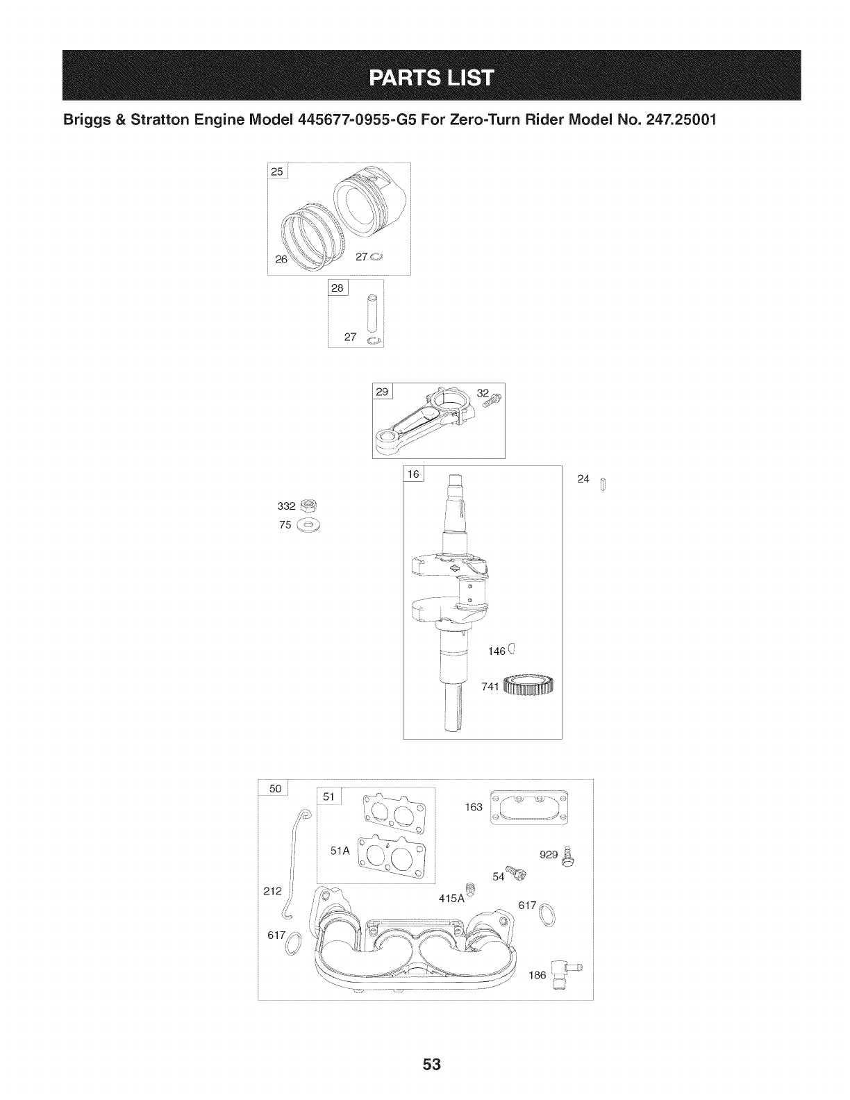
Briggs & Stratton Engine Model 445677-0955-G5 For Zero=Turn Rider Model No. 247.25001
'r
i25
26 27 <>
27 _,_
332 ':-_-:_
75 %_::_
146(_
741
24
" 50 [ 1777¸¸¸17777777777777771
_51
L
//
ff
51A 929 _
54_
_J
JJ
163 ::@/'- _4;
</
1_::,t:
186
53

Briggs & Stratton Engine IViodel 445677=0955-G5 For Zero=Turn Rider IViodel No. 247.25001
%
i
635
i
918 i
J1
1022 i
914 _ 850
1O22
883
883
1o22
36
1lOO
13
850
914 _®'
qt_
1026 _._.
"_._
1026A "'_.
337
635
54

Briggs & Stratton Engine Model 445677=0955=G5 For Zero=Turn Rider Model No. 247.25001
118
118A [
163 _. ...... ic_
\ J
k.,,\-/( ] "7
:: o'_c--j /
9 231 9
108
633 @
217 _l!I
_::_ 117A
4]_ _-......... ,.......
/,y?_/ ........\ '..
kid'
105 ;I' "
1126
1124A (.__
130
\)\
987 ;;;;;;_
UY
276 Y_<_2
r-< _ _ _S '_
1127_......_li'-i.il,, ) °_:":i
z_
276 _Jx
385
387
918
601
24O
55

Briggs & Stratton Engine Model 445677=0955=G5 For Zero=Turn Rider Model No. 247.25001
304
4
163
// i
/
/
/
467
445
967
186A_ 186B _
9_8A........... ///
__-:::...........-. _/
964 (,_
573
3O7
306A
306
56

Briggs & Stratton Engine Model 445677-0955-G5 For Zero=Turn Rider Model No. 247.25001
563
949
334
' "N
747 501
526 @_
1070
1005
332 f_
75 (_ >)
,' _, × <_ -//_!
1119
309 I"=_; 697_
789
877 /_; ........._
221 1012 _
i
216 729 l L:L:::-::::::::: /
209_,_<_ 21_ _
1054 "'_ "%_\
57
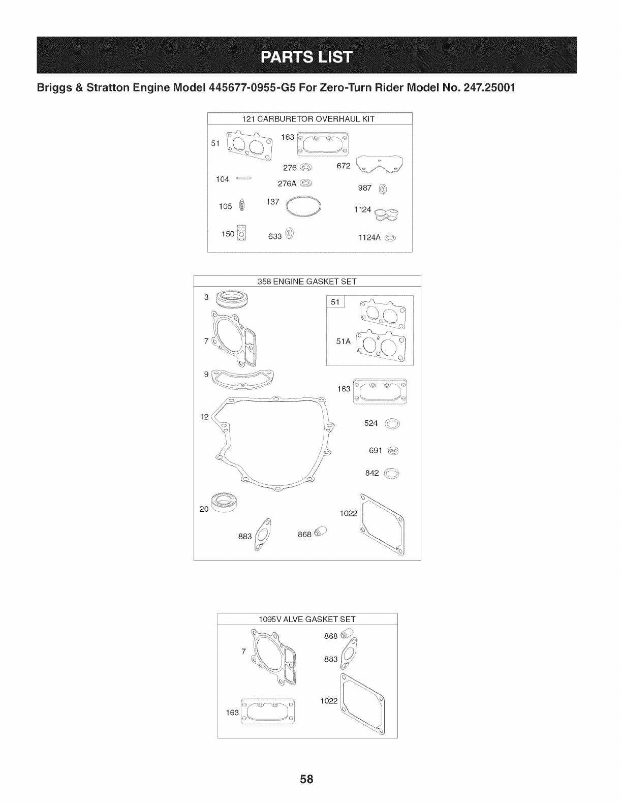
Briggs & Stratton Engine Model 445677-0955-G5 For Zero=Turn Rider Model No. 247.25001
121 CARBURETOR OVERHAUL KIT
51
_i_=_ _ _7:_ P_=_
163 i>f <:_ ,,_ "_>i
i i i i
k_\..........................................._i
r...........7................q
276 d*_' 672 k,,<,./_ ::;/ '
104 276A _::<'# 987 4;,_
,,:_jj
_ 137f .............._,
1o5 w1124 f,,,,,J_:--_
%,,,/" /
15o i_$i 633 ','_; 1124A c{7
12
2O
", t
524 #:::_
,_ //'
691 _p::::::_
842 K;:::_
1o22
883
1095V ALVE GASKET SET
868 __i
883,!_
163[ .... j_i
1o22
58

Briggs & Stratton Engine IViodel 445677=0955=G5 For Zero=Turn Rider IViodel No. 247.25001
793564 rlinderAssembly 699721 Kit-IdleSpeed
2 797673 Bushing/SealKit(MagnetoSide) i104 694918 Pin-FloatHinge
3 391086s Seal-Oil(MagnetoSide) 105 797410 Valve-FloatNeedle
4 796307 Sump-Engine 108 699723 Valve-Choke
5 799088 Head-Cylinder(Cylinder1) 117 792296 Jet-Main(Standard)(LeftJet)
5A 799089 Head-Cylinder(Cylinder2) 117A1842627 Jet-Main(Standard)(RightJet)
7 693997 Gasket-CylinderHead 118 699457 Jet-Main(High Altitude)(LeftJet)
8 792185 BreatherAssembly i118A 699733 Jet-Main(High Altitude)(RightJet)
9 690937 Gasket-Breather 121 797890 Kit-CarburetorOverhaul
10 691108 Screw(BreatherAssembly) i125 796227 Carburetor
11 792184 Tube-Breather 130 690993 Valve-Throttle
12 697227 Gasket-Crankcase i131 499805 Kit-ThrottleShaft
13 793988 Screw(CylinderHead) 133 699724 Float-Carburetor
15 794903 Plug-OilDrain 135 699729 Tube-FueITransfer
16 796237 Crankshaft 137 690994 Gasket-FloatBowl
20 795387 Seal-Oil(PTOSide) 141 i796228 Kit-ChokeShaft
22 694966 Screw(CrankcaseOover/Sump) 142 699726 Nozzle-Carburetor
23 799090 Flywheel i146 690979 Key-Timing
24 222698s Key-Flywheel(Aluminum) 150 690995 Gasket-Nozzle
25 793560 PistonAssembly(Standard) 163 691001 Gasket-AirCleaner
-- 793563 PistonAssembly(020"Oversize) 186 795985 Hose-Connector(IntakeManifold)
26 792026 RingSet (Standard) 186A 799158 Hose-Connector(EVAPSystem)
-- 792073 RingSet (.020"Oversize) 186B1845141 Hose-Connector
27 690975 Lock-PistonPin 187 791766 Line-Fuel(Cutto RequiredLength)
28 696581 Pin-Piston 188 691108 Screw(ControlBracket)
29 796209 Rod-Connecting 192 690083 Adjuster-RockerArm
32 690976 Screw(ConnectingRod) 197 697820 Screw(BackPlate)
33 793557 Valve-Exhaust 209 1798921 Spring-Governor(Orange)
34 793556 Valve-Intake 211 691019 Spring-GovernedIdle(l/0 Color)
35 694865 Spring-Valve(Intake) 212 695238 Link-Throttle
36 694865 Spring-Valve(Exhaust) 216 796229 Link-Choke
42 499586 Keeper-Valve 217 799112 Spring-ChokeReturn
45 690977 Tappet-Valve 219 793338 Gear-Governor
46 792555 Camshaft 220 799772 Washer(GovernorGear)
48 N/A ShortBlock(NotAvailableAt This Printing) 221 i841026 Cup-Governor
50 695241 Manifold-Intake 222 798915 Bracket-Control
51 795123 Gasket-Intake 227 798856 Lever-GovernorControl
51A 690950 Gasket-Intake 231 690718 Screw(ChokeValve)
53 690951 Stud(Carburetor) 239 792028 Switch-OilPressure
54 699816 Screw(IntakeManifold) 240 695666 Filter-Fuel
73 494439 Screen-Rotating 250 690957 Retainer-Breather
74 698425 Screw(RotatingScreen) 252 794389 Collector-Oil
75 691056 Washer(Flywheel) 265 691024 Clamp-Casing
95 690718 Screw(ThrottleValve) 267 792629 Screw(CasingClamp)
59

Briggs & Stratton Engine IViodel 445677=0955=G5 For Zero=Turn Rider IViodel No. 247.25001
695410 Washer-Sealing 697891 SeaI-ORing(IntakeManifold)(Red)
i278 792651 Washer(GovernorControlLever) 633 699813 Seal-Choke/ThrottleShaft(ChokeShaft)
i287 691108 Screw(DipstickTube) 635 66538s Boot-SparkPlug
i304 799955 Housing-Blower 654 690958 Nut(Carburetor)
i305 691005 Screw(BIowerHousing)(1/4-20x.68) 668 691215 Spacer(RotatingScreen)
i305A 698336 Screw(BlowerHousing) 668A 691500 Spacer(RotatingScreen)
i305B 790690 Screw(BlowerHousing)(BlowerHousingto 672 690234 Gasket-CarburetorPlate
IntakeElbow) 691 790574 Seal-GovernorShaft
306 798855 Shield-Cylinder(Cylinder2) 697 791680 Screw(DriveCap)
306A 796852 Shield-Cylinder(Cylinder1) 703 691010 Clip
307 691003 Screw(CylinderShield)(10-24x.43) 718 690959 Pin-Locating
307A 691108 Screw(CylinderShield)(1/4-20x.66) 729 797454 Clip-Wire
309 590476 Motor-Starter 741 690980 Gear-Timing
332 691059 Nut(Flywheel) 742 690328 Retainer-ERing
333 799651 Armature-Magneto 750 796208 Screw(Oil PumpCover)
334 691061 Screw(MagnetoArmature) 789 698330 Harness-Wiring
337 793541 Plug-Spark 798 697890 Screw(RockerArm)
358 694012 GasketSet-Engine 842 691031 SeaI-ORing(Dipstick)
385 797409 Screw(Fuel Pump) 847 499602 Dipstick/TubeAssembly
387 808656 Pump-Fuel 850 100106 Sealant-Liquid
404 690442 Washer(GovernorCrank) 851 493880s Terminal-SparkPlug
415 794903 Plug 865A 792286 Cover-AirGuide(Valley)
415A 794903 Plug(IntakeManifold) 868 690968 Seal-Valve
418 795912 Plate-Carburetor 877 790544 Wire/Connector-Alternator
431 798860 Elbow-Intake 883 690970 Gasket-Exhaust
445 792105 Filter-AirCleanerCartridge 914 691127 Screw(RockerCover)
447 691003 Screw(AirGuideCover) 918 797408 Hose-Vacuum(RockerCover)
462 691261 Washer(StarterCable) 918A 799160 Hose-Vacuum(EVAPSystem)
467 790697 Knob-AirCleaner 929 695239 Screw(ChokeControlBracket)
474 696457 Alternator 943 796222 SeaI-ORing(Oil PumpCover)
501 794360 Regulator 947 798779 Solenoid-Fuel
505 691029 Nut(GovernorControlLever) 949 798767 Guard-DebrisScreen
523 691036 Dipstick 964 799159 Cap-Connector
524 691032 SeaI-DipstickTube 965 796221 Cover-OilPump
525 691037 Tube-Dipstick 967 792303 Filter-PreCleaner
526 691129 Screw(Regulator) 968 795120 Cover-AirCleaner
552 796638 Bushing-GovernorCrank 975 798778 Bowl-Fuel
552A 690553 Bushing-GovernorCrank 987 691000 SeaI-ThrottleShaft
562 690311 Screw(GovernorControlLever) 1005 791236 Fan-Flywheel
563 799359 Screw(DebrisScreenGuard)(#8-18x.875) 1012 797926 Retainer-Link
573 790444 Plate-Back 1013 690954 Nipple-OilFilter
601 691038 Hose-Clamp(Black) 1017 796214 Screen-OilPump
615 698290 Retainer-GovernorShaft 1022 690971 Gasket-RockerCover
616 691045 Crank-Governor 1023 793146 Cover-Rocker(Cylinder#1)
6O

Briggs & Stratton Engine IViodel 445677=0955=G5 For Zero=Turn Rider IViodel No. 247.25001
499600 Cover-Rocker(Cylinder#2)
1024 796220 Pump-Oil
1026 690981 Rod-Push(Steel)(Exhaust)
1026A690982 Rod-Push(Aluminum)(Intake)
1027 795890 Filter-Oil
1029 690972 Arm-Rocker
Label-Emissions(Availablefroma Briggs&
1036 StrattonAuthorizedDealer)
1054 280275 Tie-Cable
1058 278776TRI
1059 698516 Kit-Screw/Washer(Alternator)
1070 791680 Screw(FlywheelFan)
1095 694013 GasketSet-Valve
1000 791959 Pivot-RockerArm
1119 691183 Screw(Alternator)
1124 690988 SeaI-ORing(FuelTransferTube)
1124A841653 SeaI-ORing(FuelTransferTube)
1126 690991 Screw(FuelTransferTube)
1127 695407 Screw(FloatBowl)
1128 690990 Screw(CarburetorNozzle)
1169 690990 Screw(CarburetorCoverPlate)
1329 ReplacementEngine(NotAvailableat this
printing)
61

Craftsman Zero=Turn Rider IViodel 247.25002
777D18808 777122282
777D18807
777S34190 777S33084
777D18808
777122885
777S33184
777S30503
777122489
To Drive(Transmission
Engage), Lift Rod hlto
LargeOpeningAnd
Release.
777123134
62
777122973
777D15548
777D18810
777X44930 (On units produced
on or before Dec. 31,2011)
MTDCONSUMERGROUPINC.
I[ ThisequipmentmeetsU.S.EPAEVP
]1 regulations for2011modelyear.
]J EVPFamily:BMTDPNHEQNC1
L_ X44930 1
777X45529 (On units produced
on or after Jan. 1,2011)
1_T_ll,$1[o]_l_o]_ii:{olll_llol:t_T_r:ll[ol_l
MTDCONSUMERGROUPINC.
Thisequipment meetsU.S.EPAEVP
regulations for2012modelyear.
EVPFamily:CMTDPNHEQNC1
X45529 .'

This page intentionally left blank. Use this page to make any notes regarding your tractor.
63

Congratulations on making a smart purchase. Your new Craftsman® product is designed and
manufactured for years of dependable operation. But like all products, it may require repair
from time to time. That's when having a Repair Protection Agreement can save you money and
aggravation.
Here's what the Repair Protection Agreement* includes:
[] Expert service by our 10,000 professional repair specialists
[] Unlimited service and no charge for parts and labor on all covered repairs
[] Product replacement up to $1500 if your covered product can't be fixed
[] Discount of 25% from regular price of service and related installed parts not covered by the
agreement; also, 25% off regular price of preventive maintenance check
[] Fast help by phone - we call it Rapid Resolution - phone support from a Sears representative.
Think of us as a "talking owner's manual."
Once you purchase the Repair Protection Agreement, a simple phone call is all that it takes for you
to schedule service. You can call anytime day or night, or schedule a service appointment online.
The Repair Protection Agreement is a risk-free purchase. If you cancel for any reason during the
product warranty period, we will provide a full refund. Or, a prorated refund anytime after the
product warranty period expires. Purchase your Repair Protection Agreement today!
Some limitations and exclusions apply. For prices and additional information in the U.S.A.
call 1=800=827=6655.
*Coverage in Canada varies on some items. For full details call Sears Canada at 1=800=361=
6665.
Sears Installation Service
For Sears professional installation of home appliances, garage door openers, water heaters, and
other major home items, in the U.S.A. or Canada call 1=800=4=MY=HOME®.
64

Look For Relevant Emissions Durability Period and
Air index information On Your Engine Emissions Label
Engines that are certified to meet the California Air Resources Board (CARB) Tier 2 Emission Standards must
display information regarding the Emissions Durability Period and the Air Index. Sears Brands Management
Corporation makes this information available to the consumer on our emission labels.
The Emissions Durability Period describes the number of hours of actual running time for which the engine is
certified to be emissions compliant, assuming proper maintenance in accordance with the Operating & Mainte-
nance Instructions. The following categories are used:
Moderate: Engine is certified to be emission compliant for 125 hours of actual engine running time.
Intermediate: Engine is certified to be emission compliant for 250 hours of actual engine running time.
Extended: Engine is certified to be emission compliant for 500 hours of actual engine running time.
For example, a typical walk-behind lawn mower is used 20 to 25 hours per year. Therefore, the Emissions
Durability Period of an engine with an intermediate rating would equate to 10 to 12 years.
The Air index is a calculated number describing the relative level of emissions for a specific engine family. The
lower the Air Index, the cleaner the engine. This information is displayed in graphical form on the emissions label.
After July 1,2000, Look For Emissions Compliance Period
On Engine Emissions Compliance Label
After July 1, 2000 certain Sears Brands Management Corporation engines will be certified to meet the United
States Environmental Protection Agency (USEPA) Phase 2 emission standards. For Phase 2 certified engines, the
Emissions Compliance Period referred to on the Emissions Compliance label indicates the number of operating
hours for which the engine has been shown to meet Federal emission requirements.
For engines less than 225 cc displacement, Category C = 125 hours, B = 250 hours and A = 500 hours.
For engines of 225 cc or more, Category C = 250 hours, B = 500 hours and A = 1000 hours.
This is ageneric representation of the emission label typically found on a certified engine.
FAMILYYBSXS.3192VA 274812
GDOC-100182Rev.B
65
(Thispageapplicableinthe U.S.A.and Canadaonly.)
Sears Brands Management Corporation (Sears), the California Air Resources Board (CARD)
and the United States Environmental Protection Agency (U.S. EPA)
Emission Control System Warranty Statement (Owner's Defect Warranty Rights and Obligations)
EMISSIONCONTROLWARRANTYCOVERAGEISAPPLICABLETOCERTI-
FIEDENGINESPURCHASEDINCALIFORNIAIN1995ANDTHEREAF-
TER,WHICHARE USEDINCALIFORNIA,ANDTOCERTIFIEDMODEL
California and United States Emission
The CaliforniaAir ResourcesBoard(CARD),U.S.EPAand Searsare pleased
to explainthe EmissionControlSystemWarrantyon your modelyear2000and
latersmalloff-roadengine(SORE).InCalifornia,newsmall off-roadengines
mustbe designed,builtand equippedto meettheState'sstringentanti-smog
standards.Elsewherein theUnitedStates,newnon-road,spark-ignition
enginescertifiedfor modelyear 1997and latermustmeetsimilarstandardsset
forthbythe U.S.EPA.Searsmustwarranttheemissioncontrolsystemon your
YEAR1997ANDLATERENGINESWHICHARE PURCHASEDANDUSED
ELSEWHEREINTHEUNITEDSTATES(ANDAFTERJANUARY1,2001 IN
CANADA).
Control Defects Warranty Statement
enginefor theperiodsoftime listedbelow,providedtherehasbeen noabuse,
neglector impropermaintenanceof your smalloff-roadengine.Youremis-
sion controlsystemincludespartssuch as thecarburetor,air cleaner,ignition
system,mufflerand catalyticconverter.Also includedmaybeconnectorsand
otheremissionrelatedassemblies.Wherea warrantableconditionexists,Sears
will repairyour smalloff-roadengineat no costto you includingdiagnosis,parts
and labor.
Sears Emission Control Defects Warranty Coverage
Smalloff-roadenginesarewarrantedrelativeto emissioncontrolpartsdefects
fora periodof one year,subjectto provisionsset forth below.Ifanycovered
Owner's Warranty
Asthe smalloff-roadengineowner,you are responsiblefor theperformanceof
therequiredmaintenancelistedin yourOperatingand MaintenanceInstruc-
tions.Searsrecommendsthatyouretainallyourreceiptscoveringmaintenance
onyoursmalloff-roadengine,butSears cannotdenywarrantysolelyfor the
lackof receiptsorfor yourfailureto ensuretheperformanceof all scheduled
maintenance.As the smalloff-roadengineowner,you shouldhoweverbe
awarethat Searsmaydenyyou warrantycoverageifyour smalloff-roadengine
ora part hasfaileddueto abuse,neglect,impropermaintenanceor unap-
parton yourengineis defective,the part willbe repairedorreplacedbySears.
Responsibilities
provedmodifications.Youare responsiblefor presentingyour smalloff-road
engineto anAuthorizedSearsServiceDealeras soonas a problemexists.The
undisputedwarrantyrepairsshouldbe completedina reasonableamountof
time,notto exceed30days.Ifyou haveanyquestionsregardingyourwarranty
rightsand responsibilities,you shouldcontacta SearsService Representative
at 1-800-469-4663.Theemissionwarrantyis a defectswarranty.Defectsare
judgedon normalengineperformance.The warrantyis notrelatedto an in-use
emissiontest.
Sears Emission Control Defects Warranty Provisions
ThefollowingarespecificprovisionsrelativetoyourEmissionControlDefectsWarrantyCoverage.ItisinadditiontotheSearsenginewarrantyfornon-regulated
enginesfoundin theOperatingand MaintenanceInstructions.
1. WarrantedParts
Coverageunderthis warrantyextendsonly to the parts listedbelow (the
emissioncontrolsystemsparts)to the extentthese partswere presenton
theenginepurchased.
a. FuelMeteringSystem
•Cold start enrichmentsystem
•Carburetorand internalparts
•FuelPump
b. AirlnductionSystem
•Aircleaner
•Intakemanifold
c. IgnitionSystem
•Sparkplug(s)
•Magnetoignitionsystem
d. CatalystSystem
•Catalyticconverter
•Exhaustmanifold
•Air injectionsystemor pulsevalve
e. MiscellaneousItemsUsedin AboveSystems
•Vacuum,temperature,position,timesensitivevalves
andswitches
• Connectorsandassemblies
2. Lengthof Coverage
Searswarrantsto the initialownerand eachsubsequentpurchaserthat
theWarrantedPartsshallbefree fromdefects in materialsandworkman-
shipwhich causedthefailure of the WarrantedPartsfor a periodof one
yearfromthe datethe engineis deliveredto a retailpurchaser.
3. NoCharge
Repairor replacementof anyWarrantedPartwill beperformedat no
chargeto the owner,includingdiagnosticlabor whichleadsto the
determinationthata WarrantedPartisdefective,ifthe diagnosticworkis
performedat an AuthorizedSears ServiceDealer.Foremissionswarranty
servicecontact yournearestAuthorizedSears ServiceDealeras listed in
the "YellowPages"under"Engines,Gasoline,""GasolineEngines,""Lawn
Mowers,"orsimilarcategory.
4. Claimsand CoverageExclusions
Warrantyclaimsshall be filed in accordancewiththe provisionsof the
SearsEngineWarrantyPolicy.Warrantycoverageshall beexcludedfor
failuresof WarrantedPartswhichare notoriginal Searspartsor because
of abuse,neglector impropermaintenanceas setforth inthe Sears
EngineWarrantyPolicy.Searsis notliableto coverfailuresof Warranted
Partscausedby theuse of add-on,non-original,or modifiedparts.
5. Maintenance
Any WarrantedPart whichis notscheduledfor replacementas required
maintenanceor whichis scheduledonly for regularinspectionto the effect
of "repairor replaceas necessary"shallbe warrantedas to defectsfor the
warrantyperiod.AnyWarrantedPartwhich is scheduledfor replacement
as requiredmaintenanceshallbe warrantedas to defectsonly forthe
periodof time up to the first scheduledreplacementfor that part. Any
replacementpart that isequivalentin performanceand durabilitymay
be usedin the performanceof any maintenanceor repairs.Theowneris
responsibleforthe performanceof all requiredmaintenance,as definedin
the SearsOperatingand MaintenanceInstructions.
6. ConsequentialCoverage
Coveragehereundershallextend to thefailure of anyenginecomponents
caused bythe failureof anyWarrantedPartstill underwarranty.
Inthe USAandCanada,a 24 hourhotline, 1-800-469-4663,has a menuof pre-recordedmessagesofferingyou enginemaintenanceinformation.
GDOC-100188Rev.B
66

FEDERAL and/or CALIFORNIA EMISSION CONTROL WARRANTY STATEMENT
YOUR WARRANTY RIGHTS AND OBLIGATIONS
MTDConsumerGroupInc,the UnitedStatesEnvironmentalProtectionAgency (EPA),and, forthose productscertifiedfor sale in the stateof California,the
CaliforniaAir ResourcesBoard(CARB)are pleasedto explainthe emission(evaporativeand/or exhaust)controlsystem(ECS) warrantyon youroutdoor2006
andlater smalloff-roadspark-ignitedengine andequipment(outdoorequipmentengine)In California,new outdoorequipmentenginesmustbe designed,built and
equippedto meetthe State'sstringentanti-smogstandards(in otherstates, 1997andlater modelyear equipmentmustbedesigned,built,and equippedto meet
theU.S. EPAsmalloff-road,sparkignitionengineregulations.MTDConsumerGroupInc mustwarrantthe ECSon your outdoorequipmentenginefor the periodof
timelisted belowprovidedtherehas been noabuse, neglector impropermaintenanceof outdoorequipmentengine.
YourECSmayincludeparts suchas thecarburetor,fuel-injectionsystem,the ignitionsystem,catalyticconverter,fuel tanks,fuel lines,fuelcaps,valves,canisters,
filters,vaporhoses,clamps,connectors,andotherassociatedemission-relatedcomponents.
Wherea warrantableconditionexists, MTDConsumerGroupIncwill repairyouroutdoorequipmentengineat no cost to youincludingdiagnosis,parts and labor.
MANUFACTURER'S WARRANTY COVERAGE:
Thisemissioncontrolsystemiswarrantedfor two years. If anyemission-relatedparton youroutdoorequipmentengineis defective,the part will berepairedor
replacedby MTDCONSUMERGROUPINC.
OWNER'S WARRANTY RESPONSIBILITIES:
Asthe outdoorequipmentengineowner,you are responsiblefor performanceof the requiredmaintenancelisted inyour owner'smanual.MTDConsumerGroup
Inc recommendsthat you retainall receiptscoveringmaintenanceon youroutdoorequipmentengine,butMTDConsumerGroupInc cannotdeny warrantysolely
forthe lackof receipts.
Asthe outdoorequipmentengineowner,you shouldhoweverbe awarethat MTDConsumerGroupInc may denyyouwarrantycoverageifyour outdoorequipment
engineor a part hasfaileddue toabuse,neglect,or impropermaintenanceor unapprovedmodifications.
Youare responsiblefor presentingyouroutdoorequipmentengineto MTDConsumerGroupInc'sdistributioncenterorservicecenteras soon asthe problem
exists.Thewarrantyrepairsshouldbecompletedin a reasonableamountoftime, notto exceed30 days.If youhavea questionregardingyour warrantycoverage,
you shouldcontactthe MTDConsumerGroupIncService Departmentat 1-800-800-7310orvia emailat http://support.mtdproducts.com
GENERAL EMISSIONS WARRANTY COVERAGE:
MTDConsumerGroupIncwarrantsto the ultimatepurchaserand eachsubsequentpurchaserthat theoutdoorequipmentengineis: Designed,built and equipped
so asto conformwithall applicableregulations;and freefromdefects in materialsand workmanshipthatcausethe failureof a warrantedpart to be identicalin all
materialrespectsto that part as describedin MTDConsumerGroup Inc'sapplicationfor certification.
The warrantyperiodbeginson thedate theoutdoorequipmentengineis deliveredto anultimatepurchaserorfirst placedintoservice.The warrantyperiodis two
years.
Subjectto certainconditionsand exclusionsasstated below,the warrantyon emission-relatedparts is asfollows:
1. Anywarrantedpart that is notscheduledfor replacementas requiredmaintenancein thewritten instructionssupplied,is warrantedforthe warrantyperiod
statedabove. Ifthe part fails duringthe periodof warrantycoverage,the partwill be repairedor replacedbyMTDConsumerGroupInc accordingto subsection
(4)below.Anysuchpart repairedor replacedunderwarrantywillbe warrantedfor the remainderof the period.
2. Anywarrantedpartthat isscheduledonly for regularinspectionin the writteninstructionssupplied iswarrantedforthe warrantyperiodstatedabove.Anysuch
partrepairedor replacedunderwarrantywill bewarrantedforthe remainingwarrantyperiod.
3. Anywarrantedpartthat is scheduledfor replacementas requiredmaintenancein thewritten instructionssuppliedis warrantedfor the periodof timebeforethe
firstscheduledreplacementdatefor that part.If the partfails beforethefirst scheduledreplacement,the part will be repairedorreplacedby MTDConsumer
GroupInc accordingto subsection(4) below.Anysuch part repairedor replacedunderwarrantywill be warrantedfor the remainderof the periodprior to the
firstscheduledreplacementpointfor the part.
4. Repairor replacementof any warrantedpart underthe warrantyprovisionshereinmustbe performedat a warrantystationat no chargeto the owner.
5. Notwithstandingthe provisionsherein,warrantyservicesor repairswill be providedat all of our distributioncentersthatare franchisedto servicethe subject
enginesor equipment.
6. Theoutdoorequipmentengineownerwill notbe chargedfor diagnosticlaborthat isdirectlyassociatedwithdiagnosisof a defective,emission-relatedwar-
rantedpart, providedthat suchdiagnosticworkis performedat a warrantystation.
7. MTDConsumerGroupInc is liablefor damagesto otherengine or equipmentcomponentsproximatelycausedby a failure underwarrantyof any warranted
part.
8. Throughoutthe off-roadengineand equipmentwarrantyperiodstatedabove,MTDConsumerGroupInc will maintaina supplyof warrantedparts sufficientto
meetthe expecteddemandfor such parts.
9. Anyreplacementpart maybe usedinthe performanceof anywarrantymaintenanceor repairsand mustbeprovidedwithoutchargeto the owner.Suchusewill
notreducethe warrantyobligationsof MTDConsumerGroupInc.
10.Add-onor modifiedpartsthat are notexemptedbythe Air ResourcesBoardmaynot beused.The useof any non-exemptedadd-onor modifiedpartsby the
ultimatepurchaserwill be groundsfor disallowinga warrantyclaims. MTDConsumerGroup Incwill notbe liable to warrantfailuresof warrantedparts caused
bythe use of a non-exemptedadd-onor modifiedpart.
WARRANTED PARTS:
The repairor replacementof any warrantedpart otherwiseeligiblefor warrantycoveragemaybe excludedfromsuch warrantycoverageif MTDConsumerGroup
Inc demonstratesthatthe outdoorequipmentenginehasbeenabused,neglected,orimproperlymaintained,and that suchabuse,neglect,or impropermainte-
nancewasthe direct causeof the needfor repairor replacementof the part.Thatnotwithstanding,any adjustmentofa componentthat hasa factoryinstalled,
andproperlyoperating,adjustmentlimitingdeviceis still eligible for warrantycoverage.Further,the coverageunderthis warrantyextendsonly to partsthat were
presentonthe off-roadengineand equipmentpurchased.
Thefollowing emissionwarrantypartsare covered(if applicable):
(1)FuelMeteringSystem
• Cold start enrichmentsystem(softchoke)
• Carburetorand internalparts (orfuel injectionsystem)
• Fuelpump
• Fueltank
(2)Air InductionSystem
• Aircleaner
• Intakemanifold
(3) IgnitionSystem
• Sparkplug(s)
• Magnetoignitionsystem
(4) ExhaustSystem
• Catalyticconverter
• SAI(Reed valve)
(5) MiscellaneousItemsUsedin AboveSystem
• Vacuum,temperature,position,timesensitivevalvesand switches
• Connectorsandassemblies
(6) EvaporativeControl
• Fuelhose
• Fuelhoseclamps
• Tetheredfuel cap
• Carboncanister
• Vapor lines
GDOC-100223Rev.A
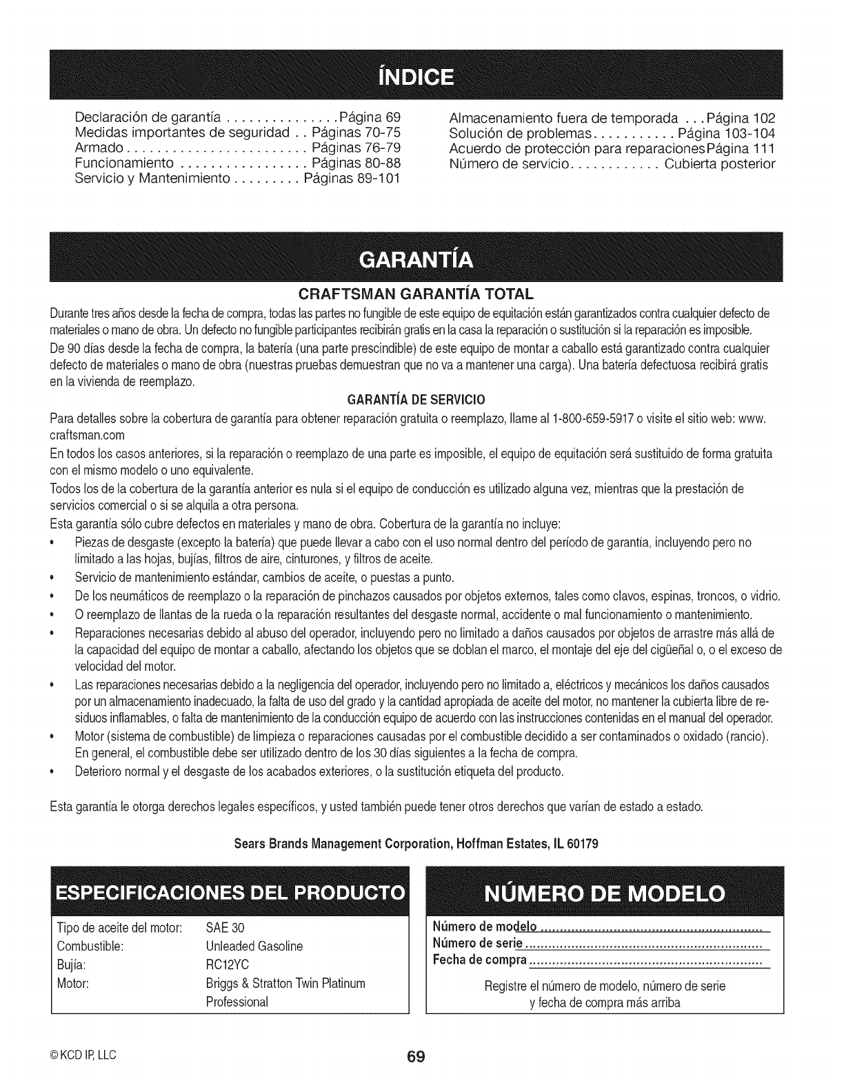
Declaraci6n de garantia ............... Pagina 69
Medidas importantes de seguridad.. Paginas 70-75
Armado ........................ Paginas 76-79
Funcionamiento ................. Paginas 80-88
Servicio y Mantenimiento ......... Paginas 89-101
Almacenamiento fuera de temporada ... Pagina 102
Soluci6n de problemas ........... Pagina 103-104
Acuerdo de proteccion para reparacionesPagina 111
NOmero de servicio ............ Cubierta posterior
CRAFTSMAN GARANTiA TOTAL
DurantetresaSosdesdelafechadecornpra,todaslaspartesnofungibledeesteequipodeequitaci6nest_.ngarantizadoscontracualquierdefectode
rnaterialeso rnanodeobra.Undefectonofungibleparticipantesrecibir&ngratisenlacasala reparaci6no sustituci6nsi lareparaci6nes irnposible.
De 90dias desdela fechadecornpra,la bateria(unaparteprescindible)deesteequipode rnontara caballoestagarantizadocontracualquier
defectode rnaterialeso rnanodeobra(nuestraspruebasdernuestranquenova a rnantenerunacarga).Unabateriadefectuosarecibir&gratis
en laviviendade reernplazo. GARANT{ADE SERVIOIO
Paradetallessobrela coberturade garantiaparaobtenerreparaci6ngratuitao reernplazo,Ilarneal 1-800-659-5917o visiteel sitioweb:www.
craftsman.corn
Entodosloscasosanteriores,si la reparaci6no reernplazodeunapartees irnposible,el equipodeequitaci6nser_susfituidode forrnagratuita
con elmisrnornodeloo unoequivalente.
Todoslosde la coberturade lagarantiaanteriores nulasi elequipodeconducci6nes utilizadoalgunavez, rnientrasque laprestaci6nde
servicioscornercialo si se alquilaa otrapersona.
Estagarantias61ocubredefectosen rnaterialesy rnanodeobra. Coberturade lagarantianoincluye:
•Piezasdedesgaste(exceptola bateria)quepuedeIlevara cabocon el usonormaldentrodel periododegaranfia,induyendoperono
lirnitadoalas hojas,bujias,filtrosde aire,cinturones,y filtrosdeaceite.
Serviciode rnantenirnientoest_ndar,carnbiosde aceite,o puestasa punto.
De losneurn_ticosde reernplazoo lareparaci6nde pinchazoscausadosporobjetosexternos,talescornoclavos,espinas,troncos,o vidrio.
0 reernplazode Ilantasde la ruedao la reparaci6nresultantesdel desgastenormal,accidenteo rnalfuncionarnientoo rnantenirniento.
Reparacionesnecesariasdebidoal abusodel operador,incluyendoperonolirnitadoa daSoscausadosporobjetosde arrastrern_salia de
la capacidaddelequipode rnontara caballo,afectandolosobjetosque se doblanel marco,el rnontajedeleje delcig(JeSalo, o el excesode
velocidaddel motor.
Las reparacionesnecesariasdebidoa lanegligenciadeloperador,incluyendoperonolirnitadoa, el_ctricosy rnec_nicoslosdaSoscausados
porunalrnacenarnientoinadecuado,la faltadeusodelgradoy lacantidadapropiadadeaceitedel motor,nomantenerlacubiertalibredere-
siduosinflarnables,ofaltadernantenirnientodelaconducci6nequipodeacuerdoconlasinstruccionescontenidasenel manualdeloperador.
Motor(sistemadecombustible)delirnpiezao reparacionescausadasporelcombustibledecididoa ser contarninadoso oxidado(rancio).
Engeneral,el combustibledebeser utilizadodentrode los30 dias siguientesa la fechade cornpra.
Deterioronormaly el desgastede losacabadosexteriores,o la sustituci6nefiquetadel producto.
Estagaranfiale otorgaderechoslegalesespecfficos,y ustedtarnbi_npuedetenerotrosderechosquevariande estadoaestado.
Sears Brands Management Corporation, Hoffman Estates, IL 60179
Tipode aceitedel motor: SAE30
Combustible: UnleadedGasoline
Bujia: RC12YC
Motor: Briggs& StrattonTwinPlatinum
Professional
NSmerode modelo ..........................................................
N_mero de serie ..............................................................
Fechade compra .............................................................
Registreel nQrnerodernodelo,nQrnerode serie
y fechade cornprarn_sarriba
© KCDIRLLC 69

Estesirnboloindicainstruccionesdeseguridadirnportantesque,de
noobservarse,podriaponerenpeligrola seguridadpersonaly /o la
propiedaddel rnisrnoya losdern_.s.Leay sigatodaslasinstrucciones
de estemanualantesdeoperarestarn_.quina.Elincurnplirnientode
estasinstruccionespuederesultarenlesionespersonales.Cuando
veaestesirnbolo,PRESTEATENCIONA SUADVERTENCIA!
PROPOSICION 65 DE CALIFORNIA
Elescapedelmotor,algunosdesuscornponentes,y ciertoscornponen-
tesdelvehiculocontienenoernitensustanciasquirnicasconocidasal
EstadodeCaliforniapotcausarc_.ncery defectosdenacirnientouotros
daSosreproductivos.
Bornesdelabateria,y accesoriosrelacionadoscontienenplornoy
cornpuestosdeplorno,sustanciasquirnicasqueelEstadodeCalifornia
quecausancancery daSosalsisternareproductivo.L_.veselasrnanos
despu_sdernanipular.
Estarn_.quinafuedise_adaparaserutilizadadeacuerdoconlaspr_.cticas
deoperaci6nseguradeestemanual.AIigualqueconcualquiertipode
equipornotorizado,oerrorpotpartedeloperariopuedecausarlesiones
graves.Estarn_.quinaescapazdearnputardedos,rnanos,dedosde
lospiesy lospiesy losrestosdelanzarniento.Elincurnplirnientodelas
instruccionesdeseguridadpuederesultarenlesionesgravesolarnuerte.
Suresponsabilidad -- Restrinjaeluso deestarn_.quinarnotor-
izadaalas personasque lea,entienday sigalas advertenciase
instruccionesde estemanualyen larn_.quina.
GUARDE ESTAS INSTRUCCIONES!
FUNCIONAIVIIENTO GENERAL
•Lea,entienday siga todaslas instruccionesde larn_.quinayen
el manual(s) antesde intentarrnontary operar.Guardeeste
manualenun lugarseguroparafuturasreferenciasy regulary
ordenarlas piezasde recarnbio.
• Estarfarniliarizadocon todosloscontrolesy su correctofuncio-
narniento.Sepac6rnodetenerla rn_.quinay desactivardeforrna
r_.pida.
• Nuncaperrnitaque ni_osrnenoresde 14a_osde edadpara
operaresta rn_.quina.Ni_osde 14a_osdebeleery cornprender
lasinstruccionesy de seguridadcontenidasenestemanualyen
larn_.quinay debenserentrenadosy supervisadosporunadulto.
• Nuncaperrnitaque losadultosa utilizarla rn_.quinasin lainstruc-
ci6n apropiada.
• Paraayudara evitarel contactoconlas cuchillaso unalesi6npor
algQnobjetoarrojado,rnantengaa los observadores,ayudantes,
ni_osy anirnalesdorn_sticospot Io rnenos75piesde distancia
de la rn_.quinarnientrasest,.en funcionarniento.Detengala
rn_.quinasi alguienentraen la zona.
• Inspeccionecuidadosarnenteel _.readondeelequipose vaa
utilizar.Retiretodaslas piedras,palos,cables,huesos,juguetes
y otrosobjetosextra_osquepodrianser recogidosy arrojados
porlacuchilla (s).Los objetoslanzadospuedencausarlesiones
personalesgraves.
• Elplandesu patr6ndecorteparaevitarladescargade material
hacialoscarninos,veredas,losobservadores,etc.Adern_.s,evite
descargarmaterialcontraunapareduobjetoquepuedacausar
descargade materialde rebotecontrael operador.
• Siernpreutilicegalasde seguridado galas deseguridaddurante
laoperaci6ny el desernpe_ode la rn_.quinaoparaprotegersus
ojos.Los objetosarrojadosque rebotanpuedencausarda_o
gravea los ojos.
• Usezapatosfuertes,de suelay zapatosde trabajoajustadacorno
pantalonesy carnisas.Ropasueltay joyaspuedenengancharse
en las piezasrn6viles.Nuncaoperela rn_.quinacon los pies
descalzoso sandalias.
Estaraltantode larn_.quinay ladirecci6ndedescargaapegoy
no el puntoquea nadie.No opereel cortacespedsin lacubierta
de descargao dec_spedtodo en su lugar.
• Nointroducirlas rnanoso los piescercade las piezasgiratorias
o bajola plataforrnadecorte. Contactocon lahoja(s) puede
arnputarrnanosy pies.
• Unacubiertadedescargafaltanteo da_adapuedecausar
contactocon lascuchillaso lesionesporobjetosarrojados.
• Detenerla hoja(s) cuandoatraviesesenderos,sendaso carninos
y aunquenoes el cortedel cesped.
• Cuidadocon el tr_.ficocuandose trabajacercade ocarreteras.
Estarn_.quinanoest,.dise_adaparasu usoen cualquiervia
pQblica.
• Nohagafuncionarla rn_.quinabajolainfiuenciadelalcoholo las
drogas.
• Corteel cespeds61ocon luz naturalo luz artificialbuena.
• NuncaIlevepasajeros.
• Retrocedalentarnente.Siernpremirehaciaabajoy haciaatr_.s
antesy rnientrasretrocede,paraevitarunaccidentede regreso
otra vez.Tengaencuentay prestaratenci6na la funci6ndel
sisternade seguridadquedetieneel poderde laspalascuando
se conduceen sentidoinverso.Si nofuctioningcorrectarnente,
p6ngaseen contactocon un distribuidorautorizadoparala
inspecci6nde seguridady reparaci6ndelsisterna.
• Reduzcala velocidadantesde girar.Operarla rn_.quinasin
problernas.Eviteel funcionarnientoerr_.ticoy el excesode
velocidad.
7O

• Desconectarlahoja(s), frenode estacionarnientoestablecidos,
apagueel motory esperarhastaquela hoja(s) Ilegara una
paradacornpletaantesde retirarde c_sped,vaciarlos recortes,
destaparel canal,retirarrestosdecespedo desechos,o hacer
cualquierajuste.
• Nuncadejela rn_.quinaenfuncionarnientosinvigilancia.Siernpre
apaguela hoja(s),lugarde las palancasde controlenla unidad
defreno neutral,estacionarnientoconjunto,apagueel motory
quitela Naveantesde bajarse.
• Tengacuidadoal cargarodescargarla rn_.quinaen unrernolque
o carni6n.Estarn_.quinanodebeser irnpulsadahaciaarribao
abajode la rarnpa(s), ya queelequipopodrfacaersey causar
lesionespersonalesgraves.Larn_.quinase debeernpujarrnanu-
alrnenteen la rarnpa(s) paracargaro descargarcorrectarnente.
• Silenciadory elmotorsecalientany puedencausarunaque-
rnadura.Nose tocan.
• Cornpruebeel espaciolibreencirnade lacabezaantesde
conduciren condicionesde pocararnasde los _.rbolescolgantes,
cables,etc puertaaperturas,en lasqueel operadorgolpeadoo
sacadodela rn_.quina,Io quepodrfaresultaren lesionesgraves.
• Desenganchetodoslos ernbraguesarchivoadjunto,el frenode
rnanoa la posici6n"ON"y moverel RHy LHpalancasde control
hastala posici6ndepuntornuertoantesdeintentararrancarel
motor.
• La rn_.quinaest,.dise_adaparacortarel c_spedresidencialnor-
malde unaalturadeno rn_.sde 10".No tratede cortaratrav_s
inusualrnentealto,hierbaseca(pot ejernplo,pastos)o pilasde
hojassecas.Hierbay las hojassecaspuedencornunicarsecon
el escapedelmotory /o se acurnulanen laplataforrnade corte
presentanun riesgopotencialdeincendio.
• Utilicesolarnenteaccesoriosy aditarnentosaprobadosparaesta
rn_.quinaporel fabricantede la rn_.quina.Lea,entienday siga
todaslas instruccionesquevienenconel accesorioaprobadoo
unarchivoadjunto.
• Losdatosindicanque losoperadoresde 60a_os y rn_.s,est_.n
involucradosen ungranporcentajedecortacespedlesiones
relacionadas.Estosoperadoresdebenevaluarsucapacidadpara
operarel ridingmowercortacespedenforrnasuficienternente
seguraparaprotegersea sf rnisrnosya los dern_.sdeuna lesi6n
grave.
• Si se presentansituacionesquenoest_.ncubiertosen este
manual,tengacuidadoy buenjuicio.P6ngaseencontactocon la
Lfneade Ayuda1-800-659-5917Craftsmanen laasistencia.
PENDIENTE DE LA OPERACI6N
Laspendientesson unfactorirnportanterelacionadocon lap_rdidade
controly unaccidentedevuelco,quepuederesultarenlesionesgraves
o larnuerte.Todaslaspistasrequierenrnuchaprecauci6n.Si nose
puederetrocederenla pendienteo si sesienteseguro,noIocorte.
Parasu seguridad,useel indicadorde pendientesquese incluye
cornopartede estemanualpararnedirlapendienteantesdeoperar
estarn_.quinaen unazonainclinada.Si la pendientees mayorde 15
gradoscornose rnuestraen el rnedidor,noopereesta rn_.quinaen que
lalesi6no la zona,podrfaproducirse.
Hacer:
• Corteel c_spedenpendientes,node arribaaabajo.Tenga
rnuchocuidadoal carnbiarde direcci6nen las pendientes.
• Atentoa los hoyos,surcos,baches,piedrasu otrosobjetos
ocultos.Elterrenodesniveladopuedevoltearlarn_.quina.La
hierbaaltapuedeocultarobst_.culos.
• A bajavelocidad.ElijaunavelocidadIosuficienternentebajapara
que ustednotendr_,quepararen la pendiente.Evitearrancaro
detenerseen unapendiente.Silos neurn_.ticossonincapacesde
rnantenerlatracci6n,desenganchelas cuchillasy procederlenta
y cuidadosarnentehaciaabajode la pendiente.
• Sigalas recornendacionesdelfabricanteparalos pesoso
contrapesosde ruedaspararnejorarla estabiNdad.
• Tengacuidadocon loscolectoresde hierbau otrosaccesorios.
EstospuedencarnbiarlaestabiNdadde la rn_.quina.
• Quetodoslos rnovirnientosen las laderaslentoy gradual.
No realicecarnbiosbruscosde velocidado direcci6n.R_.pida
aceleraci6no desaceleraci6npodrfahacerqueel frontalde la
rn_.quinase levantey darsela vueltahaciaatr_.s,Io quepodrfa
causarlesionesgraves.
Nosedebe:
•Noenciendalas laderasrnenosque seanecesario,y luegogirar
lentarnentehaciaarribay tengasurnocuidadoen lascurvas.
• Nocorteel c_spedcercade desniveles,zanjasoterraplenes.El
cortac_spedpodrfagirarsobresi unaruedaest,.sobreel horde
de unacantilado,zanja,o si unhordecuevaspulg
• NointenteestabiNzarlarn_.quinaponiendoel pie enel suelo.
• Noutiliceuncolectordec_speden pendientespronunciadas.
• Nocorteel cespedrnojado.Unarnenortracci6npodrfacausar
deslizarniento.
• Notire del rernolquepesadodetr_.sdeaccesorios(porejernplo,
carrocargadodedescarga,rodiNosdecesped,etc)en pendien-
tes dern_.sde5 grados.Cuandose va cuestaabajo,el excesode
pesotiendea ernpujarel ridingmowery puedehacerqueusted
pierdaelcontrol(porejernplo,ridingmowerse puedeacelerar,
frenary dirigirla capacidadse reduce,elapegopuedenavajay
unridingmowercausaparaanular).
71

N QOS
Puedenocurriraccidentestr_.gicossi eloperadornoest,.atentoa
la presenciadelos niSos.LosniSosson a rnenudoatraidosporla
rn_.quinay la actividadde siega.EIIosnoentiendenlos peligros.
Nuncaasurnaquelos niSosperrnanecer_.nenla Qltirnavezquelos vi.
•Mantengaa los niSosfuera del_.readetrabajoyen elcuidado
vigilantede unadultoresponsableque noseael operador.
•Est_alerta y apaguela rn_.quinasi unniSoentraen el_.rea.
•Paraevitarretrasosenlos accidentes,siernprernirarhaciaatr_.s
y haciaabajoparalos niSospequeSos.
•NuncaIleveniSos,inclusocon la hoja(s) se apagar&Podrian
caersey lastirnarseseriarnenteo interferircon laoperaci6n
segurade la rn_.quina.
•Tengarnuchocuidadoal acercarsea esquinasciegas,portales,
arbustos,_.rbolesuotrosobjetosquepuedanbloquearsu visi6n
de unniSoquepuedefuncionaren elcarninode la rn_.quina.
•Mantengaa los niSosalejadosdelos rnotoresenfuncionarniento
ocaliente.Sepuedensufrirquernadurascon unsilenciador
caliente.
•Retirela Ilavecuandola rn_.quinaest,.sin vigilanciaparaevitarel
uso noautorizado
NuncaperrnitaqueniSosrnenoresde 14aSosdeedadparaoperar
estarn_.quina.NiSosde 14aSosdebeleery cornprenderlas instruc-
cionesy de seguridadcontenidasenestemanualyen larn_.quinay
debenser entrenadosy supervisadospor unadulto.
REIVlOLQUE
Rernolque_nicarnentecon unarn&quinaquetenga unenganche
diseSadopararernolcar.No rernolcadoexceptoen el puntode
enganche.
Sigalas recornendacionesdel fabricanteen los lirnitesde pesoparael
equipodearrastrey rernolqueen pendientes.
NuncaperrnitaqueniSosu otraspersonaso sobrelosequipos
rernolcados.
Enlas pendientes,el pesodelequiporernolcadopuedecausar
perdidadetracci6ny la perdidadecontrol.
Viajelentarnentey dejedistanciaadicionalparadetenerse.
Nocarnbiea neutraly lacostaabajo.
Notire del rernolquepesadodetr_.sde accesorios(porejernplo,carro
cargadodedescarga,rodillosdec_sped,etc)enpendientesde rn_.s
de5 grados.Cuandose va cuestaabajo,el excesode pesotiendea
ernpujarel ridingmowery puedehacerqueustedpierdael control(por
ejernplo,ridingmowerse puedeacelerar,frenary dirigirlacapacidad
se reduce,elapegopuedenavajay unridingmowercausapara
anular).
SERVIClO
El manejoseguro de la gasolina:
Paraevitarlesionespersonaleso daSosrnaterialesdeuso extrerno
cuidadoal rnanipularla gasolina.Lagasolinaes altarnenteinflarnable
y susvaporesson explosivos.Lesionespersonalesgravespueden
ocurrircuandolagasolinase haderrarnadosobreti rnisrnoo sobre
la ropaquese puedeincendiar.L_.veselapiel y c_.rnbiesede ropa
inrnediatarnente.
•Utilices61orecipientesparagasolinaautorizados.
•NuncaIlenelos recipientesdentrode unvehiculoo enun carni6n
o rernolquecon unrevestirnientode pl_.stico.Coloquesiernprelos
recipientesenel suelolejosde suvehiculoantesdeIlenaflos.
•Cuandoseafactible,retireelequipoa gasolinadelcarni6no
rernolquey II_neloenel suelo.Si estonoes posible,Ileneel
equipoen un rernolquecon uncontenedorport_.til,en lugardeun
surtidorde gasolina.
•Mantengalaboquillaencontactoconel bordedeltanquede
combustibleo laaberturadelrecipienteen todornornentohasta
que seterrninede Ilenar.No utiliceunaboquillaabiertadisposi-
tivo.
•Apaguetodosloscigarrillos,cigarros,pipasy otrasfuentesde
ignici6n.
•Nuncacarguecombustibleenla rn_.quina.
•Nuncaquitelatapa del gas o aSadircombustiblernientrasel
motorest,.calienteo en rnarcha.Dejequeel motorse enfriepor
Io rnenosdos rninutosantesde repostar.
•NuncaIleneexcesivarnenteel dep6sitodecombustible.Lleneel
tanquea norn_.sde 1/2"debajodel rondodelcuellode Ilenado
paradejarespacioparala expansi6ndelcombustible.
•Reernplacelatapade la gasolinay aprietebien.
•Si se derrarnagasolina,lirnpieel motory elequipo.Muevala
rn_.quinaa otra zona.Espere5 rninutosantesdearrancarel
motor.
•Parareducirlos fiesgosde incendio,rnantengala rn_.quinalirnpia
de hierba,hojasuotrosdesechosacurnulaci6n.Lirnpielosder-
rarnesde aceiteo combustibley elirninarlos residuosernpapado
de combustible.
•Nuncaguardela rn_.quinao el recipientedelcombustibleenel
interiordondehay unaluzde llamaabierta,chispaso pilotode un
calentadorde agua,calentador,homo,secadorde ropau otros
aparatosdegas.
•Dejeque la rn_.quinase enfrie porIornenoscincorninutosantes
de guardarla.
Servicios Generales
•Nuncaenciendaelmotoreninterioreso en un&teaconpoca
ventilaci6n.Elescapedel motorcontienernon6xidodecarbono,
un inodoro,y el gas mortal.
•Antesde lirnpiar,repararo inspeccionar,asegQresedeque la
hoja(s) y todaslas partesrn6vilesse handetenido.Desconecte
el cablede la bujiay conecteel motorparaevitarunarranque
accidental.
72

• Reviseperi6dicarnenteparaasegurarsede quelas cuchillas
se detenganporcornpletoa unplazoaproxirnadode cinco
(5) segundosdespu_sde querealiceelcontrolde la retirada
dela hoja.Si las cuchillasno sedetienenen el marcodeeste
tiernpo,avede su rn_.quinaservicioprofesionalpor Searsu otro
proveedorcalificado.
• Cornprueberegularrnenteel sisternadeenclavarnientode
seguridadparaun funcionarnientocorrecto,cornose describe
rn_.sadelanteen estemanual.Si el sisternade enclavarnientode
seguridadnofuncionacorrectarnente,quesu rn_.quinaatendidos
profesionalrnentepor Searsuotto proveedorcalificado.
• Revisela hoja(s) y lospernosdernontajedel motora intervalos
frecuentesparaunajusteadecuado.Adern_.s,unainspecci6n
visualde la hoja(s) delos da_os(pot ejernplo,desgaste
excesivo,abolladuras,rajaduras).Vuelvaacolocarla hoja(s)
con ladel fabricantedeequiposoriginales(OEM)hoja(s) s61o
aparecenenestemanual.Elusode piezasqueno curnplencon
las especificacionesdelequipooriginalpuedeconducira larnala
ejecuci6ny laseguridaddecornprorniso!
• Lascuchillasdecorteest_.nafiladas.Envuelvalacuchillao utilice
guantes,y tengarnuchocuidadocuandoefectOemantenirniento.
• Mantengatodaslastuercas,pernosy tornillosapretadospara
asegurarqueelequipoest,.encondicionesde trabajoseguras.
• Nuncaaltereel sisternade enclavarnientode seguridadu otros
dispositivosde seguridad.Cornpruebeperi6dicarnenteque
funcionencorrectarnente.
• Despu_sdegolpearunobjetoextra_o,pararel motor,desco-
necteel cablede la bujia(s) y conecteel motor.Inspeccione
rninuciosarnentela rn_.quinadecualquierda_o. Repararel da_o
antesde cornenzary operar.
• Nuncatratedehacerajusteso reparacionesa la rn_.quina
rnientrasel motorest,.funcionando.
• Cornponentesde cespedy lacubiertade descargaest_.nsujetos
a desgastey da_osquepodriaexponera las partesrn6viles
o perrnitirque searrojenobjetos.Paraprotegersu seguridad,
verifiquefrecuenternentetodosloscornponentesy de inrnediato
con (OEM)del fabricantedel equipooriginals61oaparecenen
estemanual.Elusode piezasquenocurnplencon lasespecifi-
cacionesdelequipooriginalpuedeconducira larnalaejecuci6ny
cornprorneterla seguridad!
• No carnbielaconfiguraci6ndel reguladordelmotoro el exceso
develocidadelmotor.Elreguladorcontrolalavelocidadrn_.xirna
defuncionarnientosegurodel motor.
• Mantenero reernplazarlas etiquetasdeseguridade instruc-
clones,seg[3nseanecesario.
• Observarlas leyesy los reglarnentosadecuadosdeelirninaci6n
de gas,petr61eo,etc, paraprotegerel medicarnbiente.
• Deacuerdocon la ConsumerProductsSafetyCommission
(CPSC)y los EE.UU.Agenciade Protecci6nArnbiental(EPA),
esteproductotieneunavida Qtilmediade siete(7)a_os,o 270
horasde funcionarniento.AI finalde lavida Otilmediaquela
rn_.quinainspeccionadaanualrnenteporSearsu otroproveedor
calificadoparaasegurarquetodoslossisternasrnec_.nicosy de
seguridadfuncionancorrectarnentey nousar enexceso.Elno
hacerlopuededarlugara accidentes,lesioneso larnuerte.
NO MODIFIQUE EL MOTOR
Paraevitarlesionesgraveso larnuerte,nornodifiqueel motorde
ningunarnanera.Laalteraci6nde laconfiguraci6ndel regulador
puededarlugara unmotorfueradecontroly hacerquefuncionea
velocidadespeligrosas.Nuncacarnbiela configuraci6nde f_.bricadel
reguladordelmotor.
Avisoreferidoaernisiones
Motoresqueest&ncertificadosy curnplencon lasregulaciones
federalesdela EPAy deernisi6nparaSORE(Equipospeque_ostodo
terreno)est_.ncertificadosparafuncionarcon gasolinaregularsin
plorno,y puedeincluirlossiguientessisternasdeernisi6nde control:La
rnodificaci6ndelmotor(EM)y catalizadorde tresvias(TWO)si Iotiene.
GUARDACHISPAS
Estarn&quinaest,.equipadacon unmotorde cornbusti6ninternay
nodebe serutilizadaeno cercade unterrenoagrestecubiertopor
bosque,rnalezaso hierbaexceptosi el sisternade escapedel motor
est,.equipadocon un arnortiguadordechispasquecurnplacon las
leyeslocalesoestatalescorrespondientes,encasode haberlas.
Siun supresordechispasquese utilice,debernantenerseen buenas
condicionesdetrabajoporpartedeloperador.Enel Estadode
CaliforniaIoanteriorse requiereporley (Arficulo4442delC6digode
RecursosPQblicosde California).Otrosestadospuedentenerleyes
sirnilares.Lasleyesfederalesse aplicanen tierrasfederales.
Unsupresorde chispasparael silenciadorest,.disponiblea travesde
sudistribuidorrn_.scercanode servicioautorizadodemotoro contacto
con el servicio,POBox361131Cleveland,Ohio44136-0019.
73
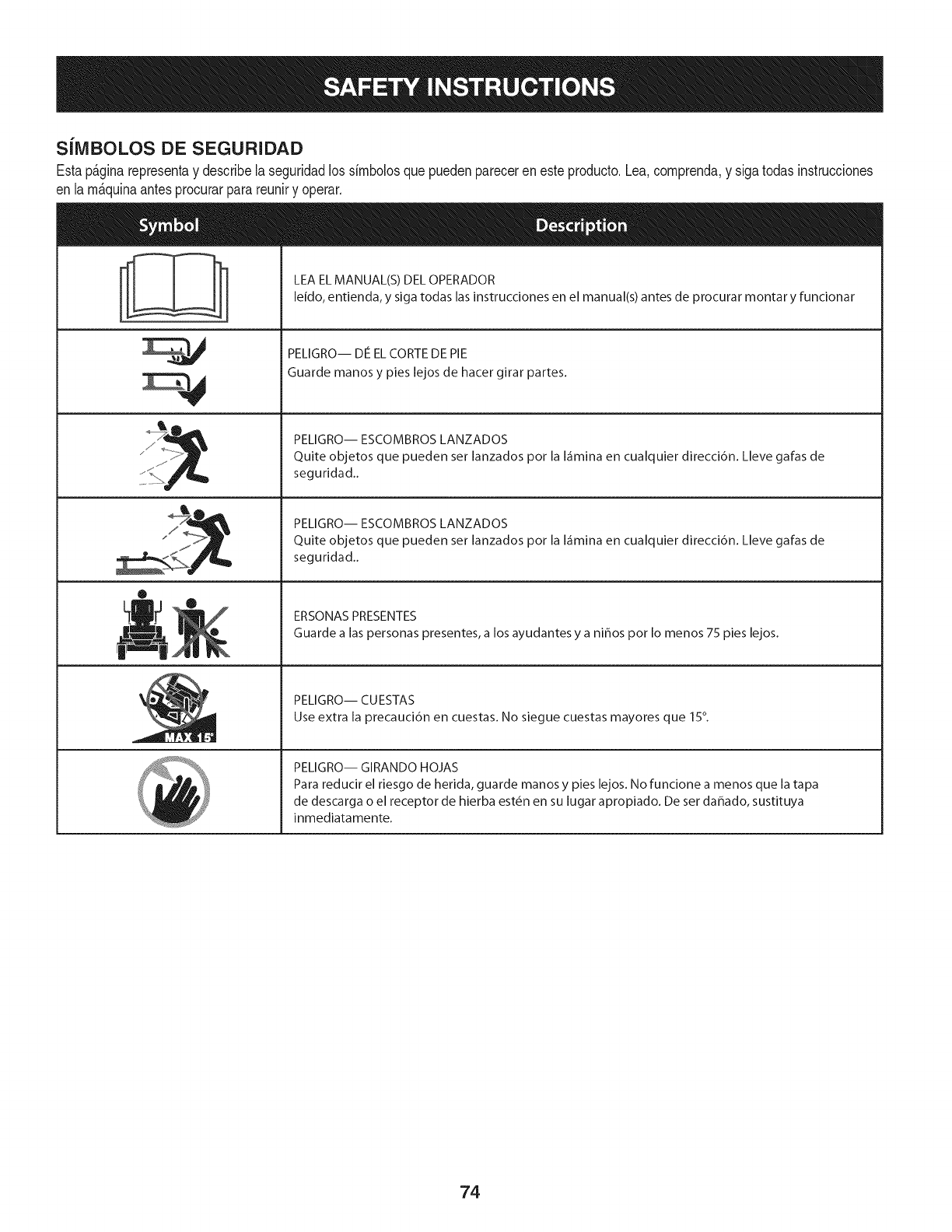
SilVIBOLOS DE SEGURIDAD
Estap&ginarepresentay describelaseguridadlos simbolosquepuedenpareceren esteproducto.Lea,comprenda,y sigatodasinstrucciones
en lam_quinaantesprocurarparareuniry operar.
ii
0
LEA EL MANUAL(S) DEL OPERADOR
leido, entienda, y siga todas las instrucciones en el manual(s) antes de procurar montar y funcionar
PELIGRO-- DE EL CORTE DE PIE
Guarde manos y pies lejos de hacer girar partes.
PELIGRO-- ESCOMBROS LANZADOS
Quite objetos que pueden ser lanzados pot la I_imina en cualquier direcci6n. Lleve galas de
seguridad..
PELIGRO-- ESCOMBROS LANZADOS
Quite objetos que pueden ser lanzados pot la I_imina en cualquier direcci6n. Lleve galas de
seguridad..
ERSONAS PRESENTES
Guarde a las personas presentes, a los ayudantes y a nihos pot Io menos 75 pies lejos.
PELIGRO-- CUESTAS
Use extra la precauci6n en cuestas. No siegue cuestas mayores que 15°.
PELIGRO-- GIRANDO HOJAS
Para reducir el riesgo de herida, guarde manos y pies lejos. No funcione a menos que la tapa
de descarga o el receptor de hierba est6n en su lugar apropiado. De ser dahado, sustituya
inmediatamente.
74

(ACEPTAR)
15° Pendiente X
(DEMASlADO ESCARPADO)
Figura1Figura2
.. 15°1fn
USODEESTEPENDIENTEDECALIBREPARADETERIVIINAR
SI UNAPENDiENTEESDEMASiAD0ESCARPAD0PARAUNA0PERACIONSEGURN
Paracomprobar lapendiente,hagaIo siguiente:
1. Borraresta p_.ginay doble a Io largo de la linea discontinua.
2. Localizarun objetovertical sobre o detr_sde la pendiente(un poste, unedificio, unavalla, un _.rbol,etc.)
3. Alineecada ladode pendientedecalibre conel objetovertical (consultarFigura 1 and Figura2 ).
4. Ajuste el pendientede calibrearriba o haciaabajohasta lostoques esquinaizquierdael pendiente
(consultar Figura1 and Figura2).
5. Si hayunespacio pot debajode la pendientedecalibre, el pendientees demasiadoescarpapot operaci6n
segura(consultar Figura2 above).
15° Pendiente
Las pendientesson un factor importante relacionadocon un vuelco y renovaci6nde los accidentesque pueden provocar lesionesgraves o la muerte.
No utilicela ma.quinaen pendientes de masde 15grados. Todos pendientesrequiere mayorprecauci6n.Si no puede retrocederen la pendiente o si se
siente inseguro en ella, no la recorte. Siempre corte el cesped en toda la superficie de la cuesta. Nunca arriba y abajo laspendientes.
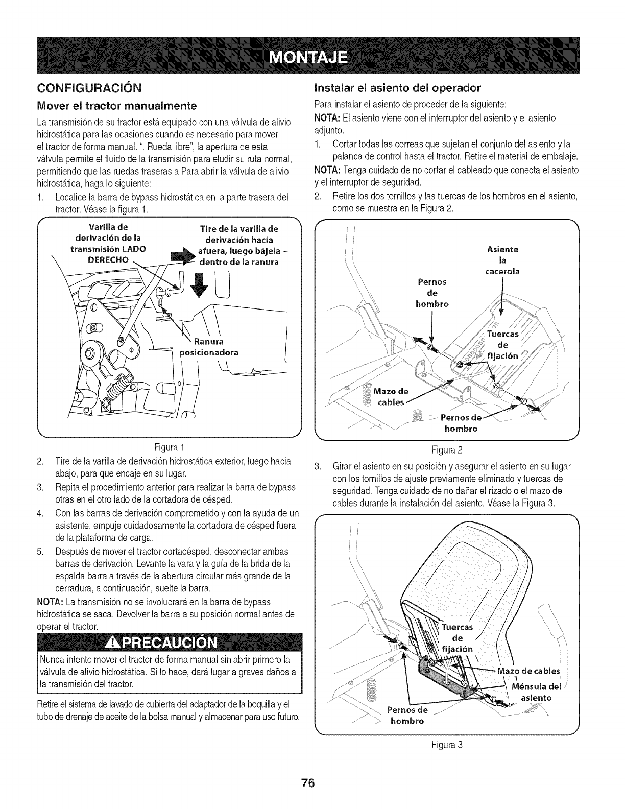
CONFIGURACION
Mover el tractor rnanualmente
Latransmisi6nde sutractorestAequipadocon unavAIvuladealivio
hidrost_ticaparalas ocasionescuandoes necesarioparamover
eltractorde formamanual.".Ruedalibre', laaperturade esta
v&Jvulapermiteelfluidode Jatransmisi6nparaeludirsu rutanormal,
permifiendoque las ruedastraserasa Paraabrir lav&lvuladealivio
hidrost&tica,hagaIosiguiente:
1. LocaJicela barradebypasshidrost&ficaen la partetraseradel
tractor.V_aselafigura 1.
Varilla de
derivaci6n de la
transmisi6n LADO
DERECHO
Tire de la varilla de
derivaci6n hacia
afuera, luege b&jela -
dentro de la ranura
Figura1
2. Tirede lavarillade derivaci6nhidrostAticaexterior,luegohacia
abajo,paraqueencajeensu lugar.
3. Repitael procedimientoanteriorpararealizarla barrade bypass
otrasen el ottoladede lacortadorade cesped.
4. Con lasbarrasdederivaci6ncomprometidoy con la ayudade un
asistente,empujecuidadosamentelacortadoradec_spedfuera
de laplataformade carga.
5. Despu_sdemoverel tractorcortacesped,desconectarambas
barrasde derivaci6n.Levantelavaray laguia dela bridade la
espaldabarraa travesde laaberturacircularm_.sgrandede la
cerradura,a continuaci6n,sueltela barra.
NOTA: Latransmisi6nno se involucrar_,en labarrade bypass
hidrost_.ticase saca.Devolverla barraa su posici6nnormalantesde
operarel tractor.
Nuncaintentemovereltractordeformamanualsinabrirprimerola
v_.lvulade aliviohidrost_.tica.SiIo hace,dar_.lugaragravesdafiosa
latransmisi6ndeltractor.
Retireelsistemadelavadodecubiertadeladaptadordelaboquillay el
tubededrenajedeaceitedelabolsamanualy almacenarparausefuture.
Instalar el asiento del operador
Parainstalarelasientode precederdela siguiente:
NOTA:Elasientovienecon el interrupterdel asientoy el asiento
adjunto.
1. Cortartodaslas correasquesujetanel conjuntodelasientoy la
palancadecontrolhastaeltractor.Retireel materialde embalaje.
NOTA: Tengacuidadode nocortarel cableadoqueconectaelasiento
y el interrupterde seguridad.
2. Retirelosdos tornillosy las tuercasde los hombresen elasiento,
comese muestraenla Figura2.
f
Asiente
la
cacerola
.
Pernesde-
hombre
Figura2
Girarelasientoen su posici6ny asegurarel asientoen su lugar
con los tornillosde ajustepreviamenteeliminadoy tuercasde
seguridad.Tengacuidadodenodafiar el rizadoo el mazede
cablesdurantela instalaci6ndelasiento.Wase la Figura3.
Pernes de
hombre
cables
M_nsula del
asiento
Figura3
76
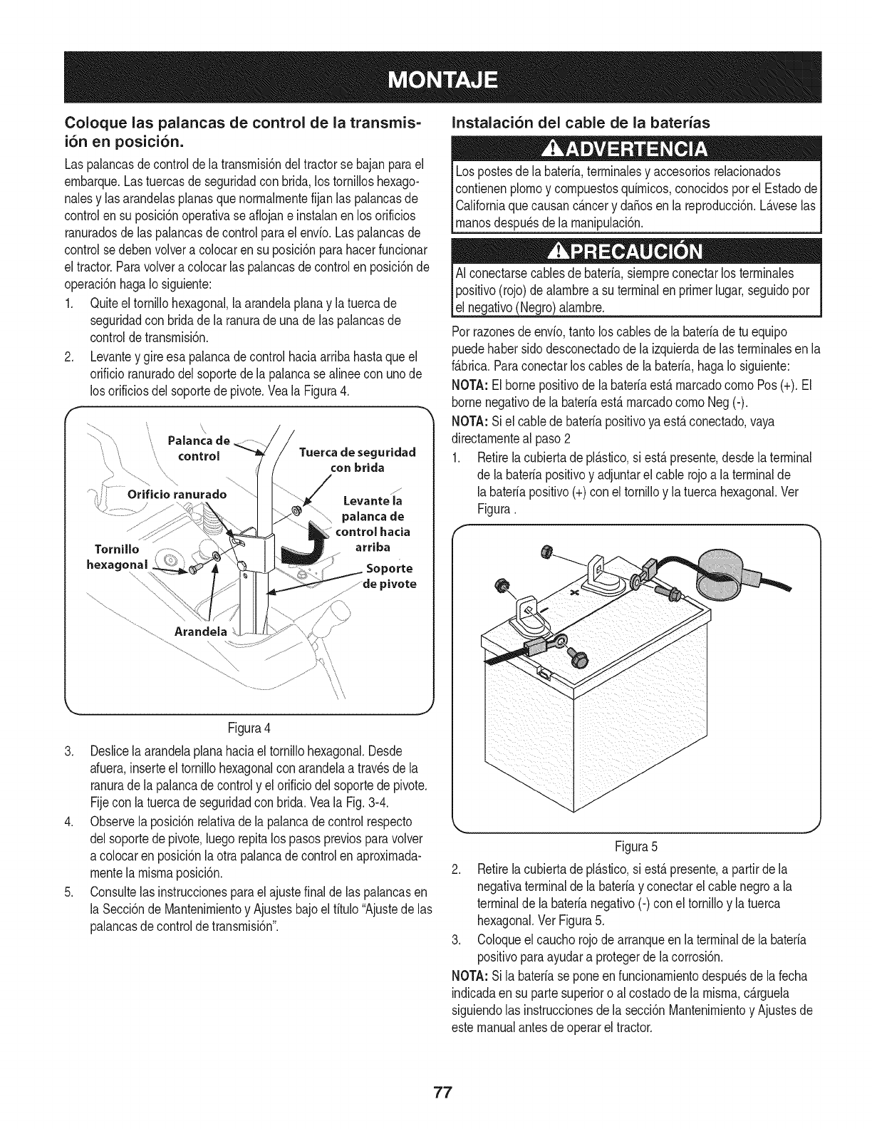
Coloque las palancas de control de la transmis=
i6n en posici6n.
Las palancasdecontroldela transmisi6ndel tractorse bajanparael
embarque.Lastuercasdeseguridadcon brida,lostornilloshexago-
nalesy las arandeJasplanasque normalmentefijanlas palancasde
controlen su posici6noperativase aflojane instalanenlos orificios
ranuradosde las pahncasde controlparael envio.Laspalancasde
controlse debenvoJvera colocaren su posici6nparahacerfuncionar
el tractor.Paravolveracolocarlas palancasdecontrolen posici6nde
operaci6nhagaIo siguiente:
1. Quiteeltornillohexagonal,laarandelaplanay latuercade
seguridadcon bridade laranurade unadelas pahncasde
controldetransmisi6n.
2. Levantey gireesa palancade controlhaciaarribahastaqueel
orificioranuradodelsoportede lapalancasealineecon unode
los orificiosdel soportedepivote.Veala Figura4.
\
Tornillo
hexagonal
\\
Paianca de
controJ Tuerca de seguridad
....,............ .... con brida
ranurado ......
Levante la
palanca de
control hacia
arriba
Soporte
...........de pivote
...............................Arandela
Figura4
3. Deslicela arandelaplanahaciael tornillohexagonal.Desde
afuera,inserteel tornillohexagonalcon arandelaa travesde la
ranurade lapalancade controly elorificiodelsoportede pivote.
Fijecon la tuercade seguridadcon brida.Veala Fig.3-4.
4. Observelaposici6nrelativade lapalancade controlrespecto
delsoportede pivote,luegorepitalos pasospreviosparavolver
a coJocarenposici6nla otrapalancade controlen aproximada-
mentela mismaposicbn.
5. Consultelas instruccionesparael ajustefinalde las palancasen
la Secci6nde Mantenimientoy Ajustesbajoel titulo"Ajustede las
palancasde controldetransmisbn".
Instalaci6n del cable de la baterias
Lospostesde la bateria,terminalesy accesoriosrelacionados
contienenplomoy compuestosquimicos,conocidosporel Estadode
Californiaquecausanc_.ncery da_osenla reproducci6n.L_.veselas
_manosdespu_sde a manpuac 6n.
AI conectarsecablesde bateria,siempreconectarlos terminales
positivo(rojo)de alambrea su terminalen primerlugar,seguidopor
el negativo(Negro)alambre.
Porrazonesdeenvio,tantoloscablesde la bateriade tu equipo
puedehabersido desconectadodela izquierdade las terminalesen la
f_.brica.Paraconectarloscablesdela bateria,hagaIosiguiente:
NOTA:Elbornepositivode labateriaest,.marcadocomoPos(+).El
bornenegativode la bateriaest,.marcadocomoNeg (-).
NOTA:Siel cablede bateriapositivoya est,.conectado,vaya
directamenteal paso2
1. Retirelacubiertade pi_.stico,si est,.presente,desdela terminal
de la bateriapositivoy adjuntarel cablerojoa laterminalde
labateriapositivo(+)con el tornilloy latuercahexagonal.Ver
Figura.
Figura5
2. Retirelacubiertade pl_.stico,si est,.presente,a partirde la
negativaterminalde la bateriay conectarelcable negroa la
terminalde labaterianegativo(-) con eltornilloy latuerca
hexagonal.VerFigura5.
3. Coloqueel cauchorojode arranqueen laterminalde labateria
positivoparaayudara protegerde la corrosi6n.
NOTA:Sila bateriase poneenfuncionamientodespu_sdela fecha
indicadaen su partesuperioro al costadode la misma,c_.rguela
siguiendolas instruccionesdela secci6nMantenimientoy Ajustesde
estemanualantesdeoperarel tractor.
77

Bajo la cubierta del canal de descarga del deflector Ajuste de las ruedas de calibraci6n
No utilicenuncalacubiertadela cortadorasinel deflectordelcanal
instaladoyen posici6nbaja.
Compruebelaplataformade corteparaunatraba deseguridad(con
etiqueta),quepuedeser la celebraci6nel deflectorhaciaarribapara
su envb. Si unaparatoest,.presente,debeserremovidoantesde
laoperaci6ndeltractor.Sosteniendoel deflectortotalmentehacia
arriba,retireeldispositivode retenci6n,sujet_.ndolay girandohaciala
derecha.Bajeel deflector.Wase la Figura6.
Figura6
Verificaci6n de Presi6n de los Neumaticos
No infiardemasiadolosneum_.ticos.Revisarel lateraldelos
neum_.ticosde psi m_.xima.Presi6nde los neum_.ticosdebedar la
mismaen todomomento.
Los neum_.ticosde sutractorpuedeserinfladaenexcesoparasu
transporte.Reducirlapresi6ndelos neum_.ticosantesdeoperarel
tractor.Revisarel lateraldelos neum_.ticosdepsi m_.xima.
Mantengalas manosy piesdedistanciadela aberturadedescarga
de laplataformadecorte.
NOTA: Las ruedasdecalibraci6nla cubiertason unafunci6nanti-
cuerode lacubiertay noest_.ndise_adosparasoportarelpesode la
plataformade corte.
Laplataforrnade cortede alturadecortese puedeajustaren cual-
quierade las seisposicionesde alturacon manejareltractorcubierta
ascensor.Laalturade la cubiertavandesde 1-1/2"a 4". Elindicador
de posici6ndela ruedade cubiertadebeserde aproxirnadamente
1/4"a 1/2" pot encimadel suelocuandola cubiertase encuentraenel
ajustede la alturadeseada.
Usandola manijade elevaci6n,ajustede lacubiertaenel ajustede la
alturadeseada,a continuaci6n,cornprobarladistanciade la ruedade
calibredesdeel suelo.Sies necesarioajustardela siguienternanera:
1. Comprobarvisualmenteladistanciaentrela ruedadelanterade
calibrey el suelo.Sila ruedaindicadorest,.cercao tocandoel
suelo,debeser levantado.Si haym_.sde 1/2"potencimadel
suelo,debereducirse.
2. Retirelatuercadefijaci6nbridade sujeci6nde la ruedadelantera
pernoindicadorde hombroa lacubierta.Retirela rueday el perno
indicadorde hombro.Refi_rasea laFigura7.
:b._....._ Pernodel Hombro
Medidor de la rueda
....... Medidor de
/_'f ruedas orificios
/' del soporte |nclice
/
/Brida de la
tuerca de
bloqueo
j
Figura7
3. Inserte el perno en el hombro uno de los cuatro agujeros de
indice en el grupo de calibre de la rueda delantera que le dar_
la rueda de calibre de 1/4" a 1/2" con la puesta a tierra y con la
tuerca de la brida.
4. Tenga en cuenta el agujero indice de la rueda acaba de ajustar,
y ajustar la rueda trasera de calibre en los agujeros indice
respectivo de la escuadra calibre otra rueda en la cubierta.
Ajuste del asiento del operador
Paraajustarla posici6ndel asiento,firelohaciaarribay sostengala
palancadeajustedel asiento.Desliceel asientohaciaadelanteo
haciaatr_.sa la posici6ndeseada;luegosueltela palancadeajuste.
AsegOresedeque elasientoest_fijo ensu posici6nantesde operarel
tractor.VealaFigura8.
78

f
Figura8
GASOLINA Y ACEITE
Recomendaciones de combustible
Usodela gasolinadeautornoci6n(gasolinasin plornoo de bajoplorno
pararninirnizarlos dep6sitosdela c_.rnaradecornbusti6n)con un
rninirnode87 octanos.Gasolinacon hastaun 10%deetanolo 15%de
MTBE(rnetilter-butil_ter)se puedeutilizar.Nuncauseuna rnezclade
aceite/gasolinao sucio.Evitarqueentresuciedad,polvooaguaen el
tanquede combustible.NO usegasolinaE85.
• Abastecersede combustibleen un_.reabienventiladay con el
motorparado.Nofumeniperrnitallamaso chispasenel _.rea
dondese Ilenaeldep6sitodel motoro dondela gasolinaes
alrnacenada.
• No Ilenedernasiadoel tanquede combustible.Despuesde
repostar,aseg_resede queeltap6ndel dep6sitoest,. bien
cerraday con seguridad.
• Tengacuidadode noderrarnarcombustibleal repostar.Vapor
derrarnadocombustibleo puedeinfiarnarse.Sise derrarna
combustible,asegQresede quela zonaest_secaantesde
arrancarel motor.
• Eviteel contactorepetidoo prolongadocon la pielo la inhalaci6n
delvapor.
A_adiendo combustible
Tengarnuchocuidadoal rnanipularlagasolina.Lagasolinaes
altarnenteinflarnabley susvaporesson explosivos.NuncaIlenar
el interiordeltractoro cuandoel motorest,.calienteoen rnarcha.
Apagarloscigarrillos,cigarros,pipasy otrasfuentesde ignici6n.
1. AsegQresede motoral airelibreyen un_.reabienventilada.
2. Lirnpieel_.reaalrededordelatapadeIlenadode combustibley
retirareltap6ndeIlenadodecombustible.
3. Elusode unrecipienteparagasolinaautorizadosrojos,a_adir
pocoa pocodecombustible,teniendocuidadode evitarquese
derrarne.
4. Llenarel tanquehastaqueelcombustibleIleguea laparteinferior
delcuellodeldep6sitodecombustible.
5. Vuelvaa colocarlatapade combustibley aprietebien.Lirnpielos 79
derrarnesdecombustibleantesdearrancarel motor.Si sederrarna
combustibleNOarranqueel motor.MuevatractorfueradelAreade
derrarne.Evitarla creaci6nde cualquierfuentedeignici6nhasta
quelosvaporesdecombustiblese banido.
El control y la adici6n de aceite
Sutractorseenviacon aceiteenel motor.Sinembargo,debecornpro-
Cornpruebesiernpreel nivelde aceiteantesde cadauso cornose
indicaen la secci6nServicioy Mantenirniento.A_adiraceitesi es
_necesaro. E no hacero puederesutar en seros da_osa su motor.
1. Coloqueel tractorcortac_spedenunasuperficieplanay
nivelada.
2. Retireeltap6nde Ilenado/varillade rnedici6ny Lirnpiela varilla.
Wase la Figura9.
Ii:l 4
Figura9
3. Insertela tapa/varillade rnedici6nen el cuellodeIlenadode
aceite,peronometerla patapulg
4. Retireeltap6nde Ilenado/varillade rnedici6n.Siel nivelest,.
bajo,agreguelentarnenteelaceitehastael nivelde aceite
registraentre FULLy ADD,la Figura8.
NOTA:No Ileneen exceso.Sobrellenadodeaceitepuedecausar
el tabaquisrno,problernasde arranque,o unachispaincrustaciones
enchufe.
5. Vuelvaa colocary aprietelatapa/varillaconfirrnezaantesde
arrancarel motor.
NOTA:NOperrnitaqueel niveldeaceitecaigapordebajode la rnarca
de TDAen lavarilla.SiIo hace,puederesultaren rnalfuncionarniento
del equipoo da_os.
NOTA:Paracarnbiarelaceiteensu motor,consultelasecci6nde
Servicioy Mantenirnientodeeste manual.
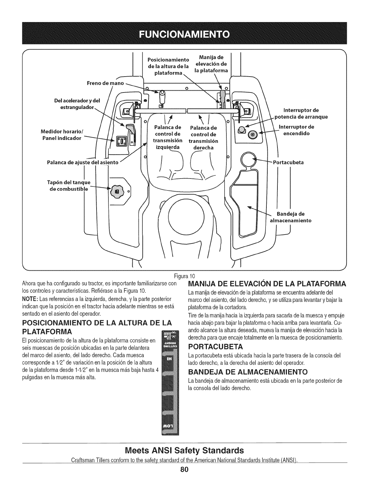
mI
Posicionamiento Manija de I I
de la altura de la elevaci6n de
plataforma la plataforma
O
Del acelerador
Qstran(
Medidor horario/
Panel indicador
Hm
Palancade Palancade
controlde controlde
transmisi6n transmisi6n
izquierda derecha
Interrupter de
.potencia de arranque
Interrupter de
encendido
Palanca de ajuste del asiento
Tap6ndel tanque
de combustible
Bandeja de
almacenamiento
Figura10
Ahoraqueha configuradosu tractor,es irnportantefarniliarizarsecon MANIJA DE ELEVACION DE LA PLATAFORMA
los controlesy caracteristicas.Refi_rasea la Figura10.
NOTE: Lasreferenciasa la izquierda,derecha,y la parte posterior
indicanque laposici6nenel tractorhaciaadelanternientrasse est,.
sentadoen el asientodel operador.
POSICIONAMIENTO DE LA ALTURA DE LA
PLATAFORNIA
El posicionarnientodela alturade la plataforrnaconsisteen
seisrnuescasde posici6nubicadasen lapartedelantera
delmarcodel asiento,delladoderecho.Cadarnuesca
correspondea 1/2"devariaci6nen la posici6nde la altura
de laplataforrnadesde 1-1/2"en larnuescarn_.sbajahasta4
pulgadasenla rnuescarn_.salta.
Larnanijade elevaci6ndela plataforrnaseencuentraadelantedel
marcodelasiento,delladoderecho,y se utilizaparalevantary bajarla
plataforrnade lacortadora.
Tirede larnanijahaciala izquierdaparasacarladela rnuescay ernpuje
haciaabajoparabajarlaplataforrnao haciaarribaparalevantarla.Cu-
andoalcancelaalturadeseada,rnuevala rnanijadeelevaci6nhaciala
derechaparaqueencajetotalrnenteen larnuescade posicionarniento.
PORTACUBETA
Laportacubetaest,.ubicadahacialapartetraserade la consoladel
ladoderecho,a laderechadel asientodeloperador.
BANDEJA DE ALIVlACENAMIENTO
Labandejade alrnacenarnientoest,.ubicadaen la parteposteriorde
la consoladelladoderecho.
Meets ANSI Safety Standards
CraftsmanTillersconformto the safetystandardof the AmericanNationalStandardsinstitute(ANSi)
80
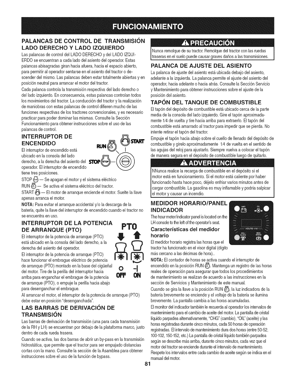
PALANCAS DE CONTROL DE TRANSMISI6N
LADO DERECHO Y LADO IZQUIERDO
Las palancasdecontroldelLADODERECHOy del LADOIZQUI-
ERDOse encuentrana cada ladodel asientodel operador.Estas
palancasabisagradasgiranhaciaafuera,haciael espacioabierto,
paraperrnitiral operadorsentarseen el asientodel tractoro de-
scenderdelrnisrno.Las palancasdebenestartotalrnenteabiertasyen
posici6nneutralparaarrancarel motordeltractor.
Cadapalancacontrolalatransrnisi6nrespectivadel ladoderechoo
delladoizquierdo.Enconsecuencia,estas palancascontrolantodos
los rnovirnientosdel tractor.Laconducci6ndeltractory la realizaci6n
dernaniobrascon estaspalancasde controldifierenrnuchode las
funcionesrespectivasdelos tractoresconvencionales,yes necesario
practicarparapoderdorninarlasrnisrnas.Consultela Secci6n
Funcionarnientoparaobtenerinstruccionessobreel uso delas
palancasde control.
INTERRUPTOR DE 6 $.I.ART
ENCENDIDO RUN
Elinterruptorde encendidoest& I
ubicadoen laconsoladel lado
derecho,a la derechadelasientodel $110P
operador.Elinterruptorde encendido
tienetresposiciones.
STOP_ -- Seapaganel motory elsisternael_ctrico
RUN_ = Seactivael sisternael_ctricodeltractor.
START_ = El motordearranqueenciendeel motor.Sueltela Nave
apenasarrancael motor.
NOTA:Paraevitarel arranqueaccidentaly/o ladescargadela
baterfa,quitela Navedel interruptordeencendidocuandoel tractorno
se encuentraen uso.
INTERRUPTOR DE LA POTENCIA
DE ARRANQUE (PTO) PT0
Elinterruptordelapotenciadearranque(PTO) _, T
est_ubicadoen laconsoladelladoderecho,a la _
derechade[asientodeloperador. ML.J
Elinterruptorde lapotenciadearranque(PTO)
hacefuncionarel ernbragueel_ctricode potencia
dearranque(PTO)rnontadoen labasedel cigQe_al 0 ='1
delmotor.Tire dela perilladel interruptorhacia
arribaparaengancharel ernbraguedela potencia _
dearranque(PTO),o ernpujelaperiNahaciaabajo
paradesengancharel ernbrague.
AIarrancarel motor,el interruptordela potenciade arranque(PTO)
debeestaren posici6n"desenganchada".
LAS BARRAS DE DERIVACION DE
TRANSMISI6N
Las barrasde derivaci6ndetransrnisi6n(unaparacada transrnisi6n
dela RHy LH) seencuentranpordebajode la plataforrnamarco,justo
dentrodecada ruedatrasera.
Cuandose activa,las dos barrasde abrirunby-passen latransrnisi6n
hidrost_.tica,queperrnitequeeltractorparaser ernpujadodistancias
cortascon la rnano.Consultela secci6nde la Asarnbleaparaobtener
instruccionessobreeluso de lafunci6nde bypass.
Nuncaremolquedesutractor.Remolquedeltractorcon lasruedas
traserasenel suelopuedecausargravesdaSosalas transrnisiones.
PALANCA DE AJUSTE DEL ASIENTO
Lapalancade ajustedelasientoest&ubicadadebajodel asiento,
adelantea la izquierda.Lapalancaperrniteel ajustedel asientodel
operador,haciaadelanteo haciaatr_.s.Consultela Secci6nServicio
y Mantenirnientoparaobtenerinstruccionessobreelajustede la
posici6ndelasiento.
TAPON DEL TANQUE DE COMBUSTIBLE
Eltap6ndeldep6sitodecombustibleest&ubicadocercade laparte
mediade laconsoladel ladoizquierdo.Gireel tap6naproxirnada-
mente1/4de vueltay tire haciaarribaparaextraerlo.Eltap6ndel
combustibleest,.arnarradoal tractorparairnpedirquese pierda.No
intenteretirarel tap6ndeltractor.
Empujeeltap6nhaciaabajosobreelcuellode Ilenadodeldep6sitode
combustibley gfreloaproximadamente1/4de vueltaen el sentidode
lasagujasdel relojparaajustarlo.Siernprevuelvaa colocarel tap6n
de maneraseguraen el dep6sitode combustibleluegodequitarlo.
NNuncarealicela recargade combustibleen eldep6sitosi el
motorest,.en funcionarniento.Si el motorest,.calienteporhaber
funcionadohastahacepoco,d_jeloenfriarvariosrninutosantesde
cargarcombustible.Lagasolinaes muyinflamabley podrfasalpicar
el motory causarunincendio.
MEDIDOR HORARIO/PANEL
INDICADOR
Thehourmeter/indicatorpanelis locatedonthe
LHconsoletotheleftoftheoperator'sseat.
Caracterfsticas del medidor
horatio
Elmedidorhorarioregistralas horasqueel
tractorhafuncionadoenel visordigital(dfgito
rn_.scercanoa lasd_cirnasde hora)..
NOTA:Elcontadordehorasse activacuandoel interruptorde
encendidoen laposici6nRUN_. Mantengaunregistrodelas horas
realesde operaci6nparaasegurarquetodoslos procedirnientos
de mantenirnientose reaNzande acuerdoalas instruccionesen la
secci6nde Serviciosy Mantenimientode estemanual.
Cuandosegira la Navea la posici6nRUN_, la luz indicadorade la
bateriabrevementeseenciendey elvoltajedela baterfase ilumina
brevernente.La pantallacarnbiaalas horasacurnuladas.
Elmonitordelindicadortambi_nle recuerdaal operadorlosintervalosde
rnantenirnientoparaelcarnbiodeaceitedelmotor.Lapantalladecristal
Ifquidoparpadeaalternativamente,"CHG"(cambio),"011"(aceite)y las
horasregistradasdurantecincominutos,cada50horasdeoperaci6n
registradas.Elintervalodernantenimientoduradoshoras(entre50-52,
100-102,150-152,etc.)LapantalladecristalIfquidotambi_nparpadea
segOnsedescribem_.sarriba,durantecincominutos,cadavezqueel
motordeltractorseenciendeduranteelintervalodemantenirniento.
RespetelosintervalosentrecadacarnbiodeaceitesegOnseindicaenel
manualdelmotor.
81
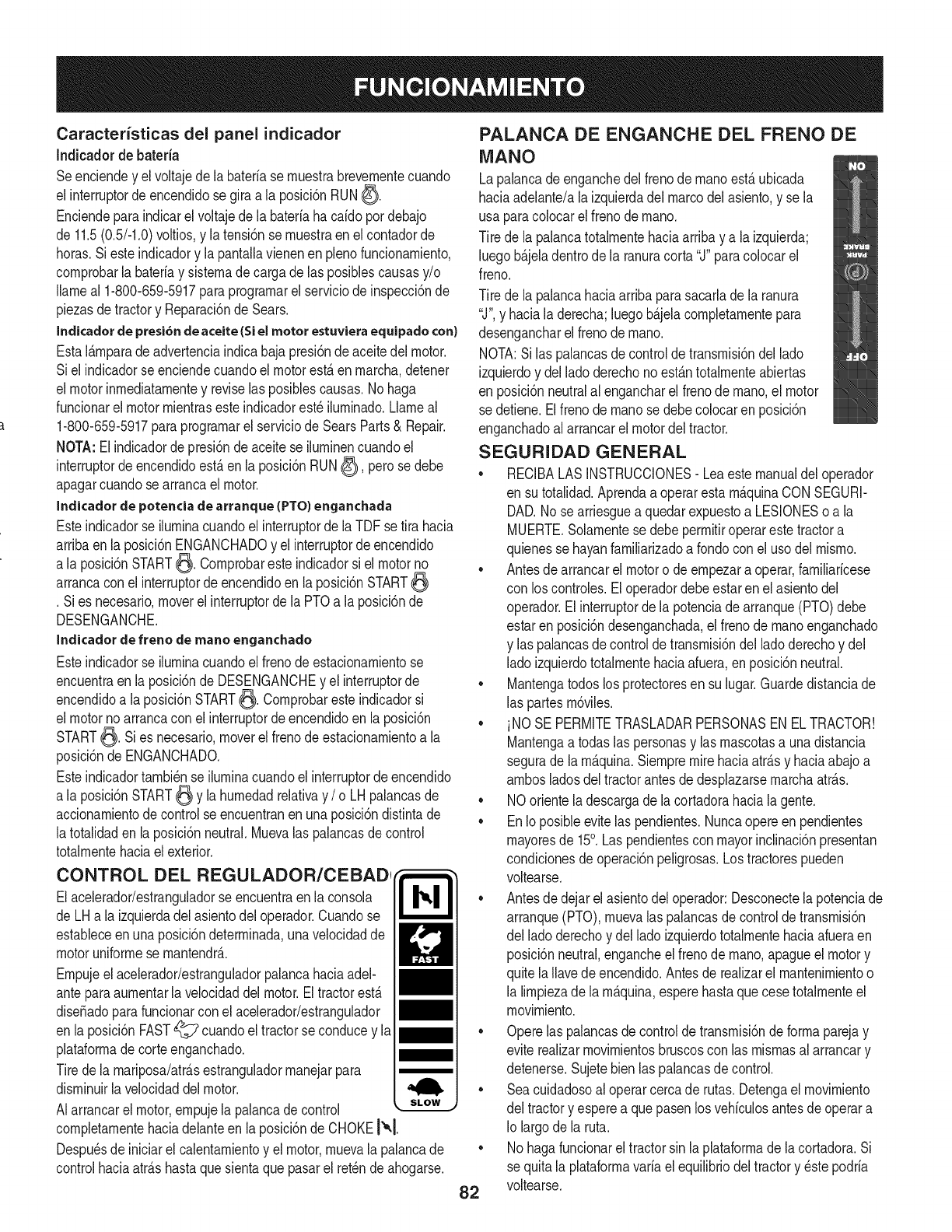
Caracteristicas del panel indicador
Indicadorde bateria
Seenciendey el voltajede la bateriase rnuestrabrevernentecuando
el interruptorde encendidosegiraa la posici6nRUN_.
Enciendeparaindicarel voltajede labateriahacaido pordebajo
de 11.5(0.5/-1.0)voltios,y latensi6nse rnuestraen elcontadorde
horas.Si esteindicadory la pantallavienenen plenofuncionarniento,
cornprobarla bateriay sisternadecarga delas posiblescausasy/o
Ilarneal 1-800-659-5917paraprograrnarel serviciode inspecci6nde
piezasdetractory Reparaci6nde Sears.
Indicador de presi6n de aceite (Si el motor estuviera equipado con}
EstaI&rnparadeadvertenciaindicabajapresi6ndeaceitedel motor.
Siel indicadorse enciendecuandoelmotorest,.en rnarcha,detener
el motorinrnediatarnentey reviselasposiblescausas.No haga
funcionarel motorrnientrasesteindicadorest_ilurninado.Llarneal
1-800-659-5917paraprograrnarel serviciode SearsParts& Repair.
NOTA:Elindicadordepresi6ndeaceitese ilurninencuandoel
interruptordeencendidoest,.enla posici6nRUN_), perose debe
apagarcuandose arrancael motor.
Indicador de potencia de arranque (PTO) enganchada
Esteindicadorse ilurninacuandoel interruptorde laTDFse tira hacia
arribaen la posici6nENGANCHADOy el interruptorde encendido
a la posici6nSTART_. Cornprobaresteindicadorsi el motorno
arrancacon el interruptorde encendidoen la posici6nSTART
.Sies necesario,moverel interruptordela PTOa la posici6nde
DESENGANCHE.
Inclicador de freno de mane enganchado
Esteindicadorse ilurninacuandoel frenode estacionarnientose
encuentraen laposici6nde DESENGANCHEy el interruptorde
encendidoa laposici6nSTART_. Cornprobaresteindicadorsi
el motornoarrancacon el interruptordeencendidoen laposici6n
START_. Sies necesario,moverelfrenode estacionarnientoa la
posici6nde ENGANCHADO.
Esteindicadortarnbi_nse ilurninacuandoel interruptordeencendido
a la posici6nSTART_ y la hurnedadrelativay /o LHpalancasde
accionarnientode controlse encuentranenunaposici6ndistintade
latotalidaden laposici6nneutral.Muevalas palancasdecontrol
totalrnentehaciaelexterior.
CONTROL DEL REGULADOR/CEBADI
Elacelerador/estranguladorse encuentraen laconsola
de LHa la izquierdadel asientodel operador.Cuandose
estableceenunaposici6ndeterrninada,unavelocidadde
motoruniforrnese rnantendr_..
Ernpujeel acelerador/estranguladorpalancahaciaariel-
anteparaaurnentarla velocidaddelmotor.Eltractorest,.
dise_adoparafuncionarconel acelerador/estrangulador
en laposici6nFAST_ cuandoel tractorse conducey la
plataforrnade corteenganchado.
Tirede la rnariposa/atr_.sestranguladorrnanejarpara
disrninuirla velocidaddel motor.
AIarrancarel motor,ernpujela palancadecontrol
cornpletarnentehaciadelanteen laposici6nde CHOKE!'°.1.
Despu_sdeiniciarel calentarnientoy el motor,rnuevala palancade
controlhaciaatr_.shastaquesientaque pasarel retchde ahogarse.
PALANCA DE ENGANCHE DEL FRENO DE
MANO
Lapalancade enganchedel frenodernanoest,.ubicada
haciaadelante/ala izquierdadel marcodelasiento,y se la
usa paracolocarelfreno dernano.
Tire de lapalancatotalrnentehaciaarribay a la izquierda;
luegob_.jeladentrodela ranuracorta"J"paracolocarel
freno.
Tire de lapalancahaciaarribaparasacarlade la ranura
"J",y haciala derecha;luegob_.jelacornpletarnentepara
desengancharel frenodernano.
NOTA:Si las palancasde controldetransrnisi6ndellado
izquierdoy del ladoderechonoest_.ntotalrnenteabiertas
en posici6nneutralal engancharel frenode rnano,el motor
se detiene.Elfrenode rnanose debecolocaren posici6n
enganchadoal arrancarel motordeltractor.
SEGURIDAD GENERAL
•RECIBALASINSTRUCCIONES-Leaestemanualdel operador
en su totalidad.Aprendaa operarestarn_.quinaCONSEGURI-
DAD.No se arriesguea quedarexpuestoa LESIONESoa la
MUERTE.Solarnentese debeperrnitiroperarestetractora
quienesse hayanfarniliarizadoa rondocon el usodel rnisrno.
• Antesde arrancarel motoro de ernpezara operar,farniliaricese
con los controles.El operadordebeestaren elasientodel
operador.Elinterruptordela potenciadearranque(PTO)debe
estaren posici6ndesenganchada,elfreno dernanoenganchado
y las palancasdecontroldetransrnisi6ndelladoderechoy del
ladoizquierdototalrnentehaciaafuera,enposici6nneutral.
• Mantengatodoslos protectoresen su lugar.Guardedistanciade
las partesrn6viles.
• iNO SE PERMITETRASLADARPERSONASEN ELTRACTOR!
Mantengaa todaslas personasy lasrnascotasa unadistancia
segurade larn_.quina.Siernpremirehaciaatr_.sy haciaabajoa
arnbosladosdel tractorantesdedesplazarsernarchaatr_.s.
• NOorienteladescargadela cortadorahaciala gente.
• EnIoposibleevitelas pendientes.Nuncaopereen pendientes
rnayoresde 15°. Laspendientescon mayorinclinaci6npresentan
condicionesdeoperaci6npeligrosas.Los tractorespueden
voltearse.
• Antesde dejarelasientodel operador:Desconectelapotenciade
arranque(PTO),rnuevalas palancasde controldetransrnisi6n
del ladoderechoy del ladoizquierdototalrnentehaciaafueraen
posici6nneutral,engancheelfrenode rnano,apagueel motory
quite laIlavedeencendido.Antesde realizarel rnantenirnientoo
la lirnpiezade la rn_.quina,esperehastaquecesetotalrnenteel
rnovirniento.
• Operelas palancasdecontroldetransrnisi6ndeforrnaparejay
eviterealizarrnovirnientosbruscoscon las rnisrnasal arrancary
detenerse.Sujetebienlas palancasde control.
• Seacuidadosoal operarcercade rutas.Detengaelmovirniento
del tractory esperea quepasenlos vehiculosantesdeoperara
Io largodela ruta.
• Nohagafuncionarel tractorsin laplataforrnade lacortadora.Si
se quita la plataforrnavaria elequilibriodeltractory _stepodria
voltearse.
82

• Eviteoperaren superficiesdetracci6ninestables;tengaextrema
precauci6nsi la superflciees resbaladiza.
• Reduzcalavelocidadantesdegirary det_ngasecompletamente
encualquiermaniobradegirocero.
•No detenganiestacioneel tractorsobrematerialescombustibles
talescomepasteu hojassecas,desechos,etc.
• No Ileneel tanquedecombustibleconel motoren funciona-
mientoo si el mismoest,.caliente.Dejeenfriarel motorvaries
minutesantesde la recargadecombustible.Aprieteeltap6nde
combustiblecon firmeza
ANTES DE HACER FUNClONAR EL TRACTOR
Beforeyou operatethe tractor,studythis manualcarefullyto
familiarizeyourselfwiththe operationof allthe instrumentsand
controls.Ithas beenpreparedto helpyouoperateand maintain
yourtractorefficiently.
• Thisengineis certifiedto operateonlyon clean,fresh,unleaded
regulargasoline.For bestresults,fill thefuel tankwithonlyclean,
fresh,unleadedgasolinewitha pumpstickeroctaneratingof 87
orhigher.
• Unleadedgasolineis recommendedbecauseit leavesless
combustionchamberdepositsand reducesharmfulexhaust
emissions.Leadedgasolineis not recommendedand mustnotbe
usedwhereexhaustemissionsareregulated.
NOTA:Compregasolinaen pequeSascantidades.No utilicegasolina
sobrantede latemporadaanterior,paraminimizarlosdep6sitosde
gomaenel sistemadecombustible.
• Elgasohol(hasta10%dealcoholetilico,90%de gasolinasin
plomopervolumen)es un combustibleaprobado.
• El_ter metilicoterciario-butilico(MTBE)y Insmezclasde
gasolinasin plomo(hastaun m_.ximode 15%de MTBEper
volumen)son combustiblesaprobados.Nose apruebael use de
otrasmezclasdegasolina/eter.
• Reviseel niveldeaceitedelmotor.
• Limpieelfiltrodeaire si es necesario.
• Controlela presi6nde infladodelos neum_.ticos.
• Ajusteel asientoparala mayorcornodidaddeloperador,para
unaadecuadavisibilidady paramantenerel controlcompletedel
tractor.
SISTEIVlA DE BLOQUEO DE SEGURIDAD
EstetractorestAequipadocon un sistemade bloqueode seguridad
paralaproteccidndeloperador.Siel sistemade bloqueofunciona
rnal,nohacerfuncionarel tractor.Llameal 1-800-659-5917para
programarel serviciodeSearsParts& Repair.
• Elsistemade bloqueode seguridadevitaqueel motorintente
arrancaro arranquea menosquese rnuevanInspalancasde
controldetransmisidndel ladederechoy delladeizquierdo
totalmentehaciaafueraen posici6nneutral,se engancheel freno
maney se desenganchela potenciadearranque(PTO).
• Paraevitarunmovimientobruscoaldesengancharel frenode
mane,el sistemade bloqueode seguridadapagael motorsi las
palancasde controldetransmisi6ndel ladederechoy/odel lade
izquierdose muevena unaposici6ndistintade latotalmente
neutralcon el frenodemaneenganchado.
• Siel operadorabandonasu asientoantesdecolocarel frenode
mane,el sistemadebloqueode seguridadapagael motor.
• Siel operadorabandonasu asientocon la potenciadearranque
(PTO)enganchada,seencuentreo nocolocadoel frenode
mane,el sistemadebloqueode seguridadapagael motor.
NOTA:Elinterrupterdela potenciadearranque(PTO)sedebemover
a la posici6n"OFF"(apagado)paravelveta arrancarel motor.
• Elsistemade bloqueodeseguridadapagala potenciade
arranque(PTO)y Inscuchillasde lacortadorase detienensi Ins
dos palancasde controlde transmisidnse muevena la posici6n
de marchaatr_.s.Lapotenciadearranque(PTO)sevuelvea
engancharcuandounao Insdos palancasse rnuevennueva-
montea la posici6nneutralo de marchadirecta.
ENCENDIDO DEL MOTOR
Estaunidadest_equipadacon un sistemade bloqueode seguridad
paraprotecci6ndel operador.No opereel tractorsi algunaparte
del sistemade bloqueofuncionareal.Controleperi6dicamenteIns
funcionesdel sistemade bloqueoparaverificarque funcionen
adecuadamente.
Perrazonesdeseguridadpersonal,el operadordebeestarsentado
enel asientodeltractoral arrancarel motor.
1. Eloperadordebeestarsentadoen elasientodel tractorcon Ins
dos palancasde controlde launidadhaciael exteriora cadalade
de la posicidnde puntomuerto/arranque.
2. Coloqueel frenode mane0. Consultela Figura11.
Paianca de control
del lade izquierdo
hacia afuera en Freno de mane
posici6nneutral enganchado
0 0 €'_1
Controldel regulador-",
Palancade control
del ladederecho
haciaafuera en
posici6n neutral
totaJmente hacia Interrupter d.=la potencia de
adelante a la posici6n- arranque (PTO) en posici6n
de "cebador". baja (desenganchada)
Figura11
3. Verifiquequeel interrupterde la potenciadearranque(PTO)
seencuentreen posici6ndesenganchada(abajo).Consultela
Figura11.
4. Coloquelapalancadecontroldel regulador/cebadortotalmente
haciaadelante,en la posici6nCHOKE!'_,1(cebador).
NOTA:Siel motorest,.caliente,tal veznosea necesariocolocarel
controldel regulador/cebadorenla posicidndelCHOKEI_.[
83
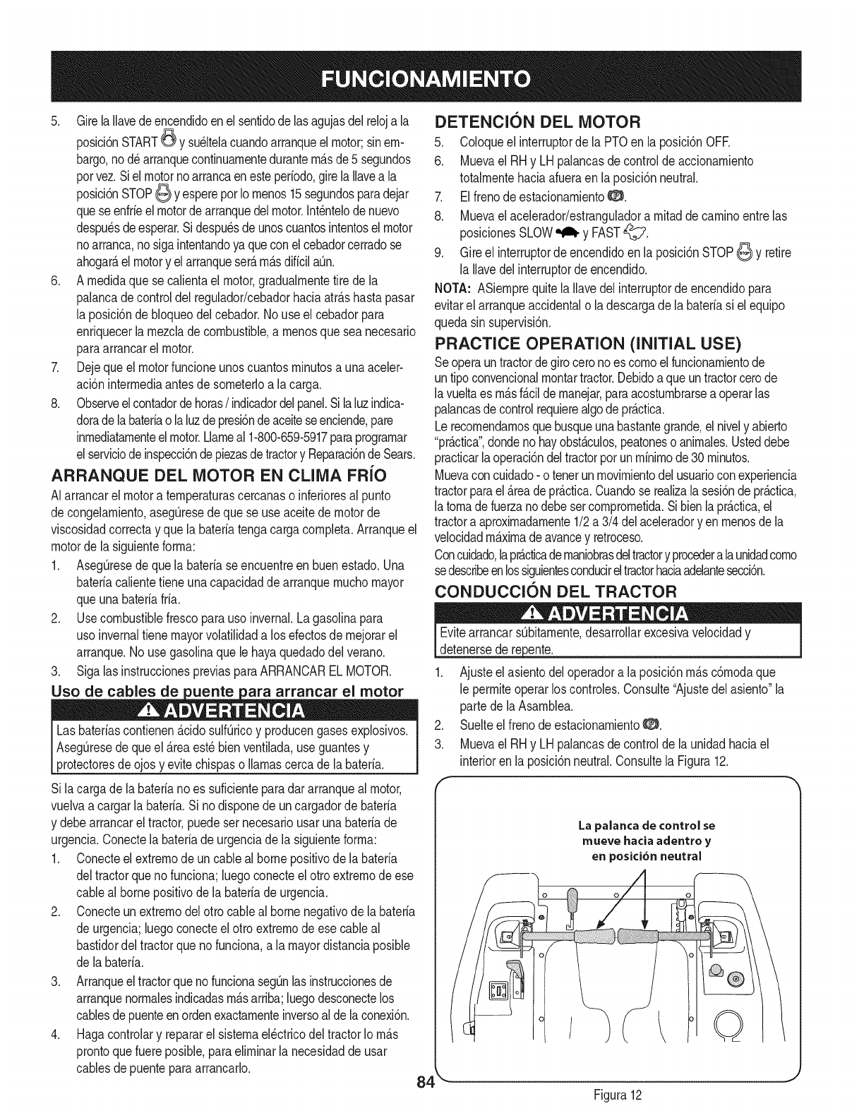
5. Girela Ilavedeencendidoenelsentidode lasagujasdelreloja la
posici6nSTART_ y su_ltelacuandoarranqueelmotor;sinem-
bargo,nod_arranquecontinuarnentedurantern_.sde5 segundos
porvez.Siel motornoarrancaenesteper[odo,girelaIlavea la
posici6nSTOP6 YespereporIornenos15segundosparadejar
queseenfr[eel motorde arranquedelmotor.Int_ntelode nuevo
despu_sdeesperar.Sidespu_sde unoscuantosintentoselmotor
noarranca,nosigaintentandoyaqueconel cebadorcerradose
ahogar_,elmotory elarranqueser_.rn_.sdificilaOn.
6. A rnedidaquese calientael motor,gradualrnentetire de la
palancadecontroldel regulador/cebadorhaciaatr_.shastapasar
la posici6nde bloqueodelcebador.No useel cebadorpara
enriquecerlarnezclade combustible,a rnenosque seanecesario
paraarrancarelmotor.
7. Dejequeel motorfuncioneunoscuantosrninutosa unaaceler-
aci6ninterrnediaantesde sorneterloa lacarga.
8. Observeelcontadordehoras/indicadordelpanel.Silaluzindica-
doradelabateriaolaluzdepresi6ndeaceiteseenciende,pare
inrnediatarnenteelmotor.Llarneal 1-800-659-5917paraprograrnar
elserviciodeinspecci6ndepiezasdetractory Reparaci6ndeSears.
ARRANQUE DEL MOTOR EN CLIMA FR{O
AIarrancarel motora ternperaturascercanaso inferioresal punto
decongelarniento,asegQresede quese useaceitedemotorde
viscosidadcorrectay que la bateriatengacargacornpleta.Arranqueel
motorde lasiguienteforrna:
1. AsegQresedequela bateriaseencuentreen buenestado.Una
bateriacalientetieneunacapacidadde arranquernuchomayor
queunabateriafria.
2. Usecombustiblefrescoparauso invernal.Lagasolinapara
uso invernaltiene mayorvolatilidada losefectosde rnejorarel
arranque.Nouse gasolinaquele hayaquedadodelverano.
3. Sigalas instruccionespreviasparaARRANCARELMOTOR.
Uso de cables de uente ara arrancar el motor
Lasbater[ascontienen&cidosulf_ricoy producengasesexplosivos.
AsegQresede queel _.reaest_bienventilada,useguantesy
protectoresde ojosy evitechispaso llamascercade labater[a.
Si lacargade labater[anoes suficienteparadararranqueal motor,
vuelvaa cargarlabater[a.Si nodisponedeuncargadorde bater[a
y debearrancarel tractor,puedesernecesariousarunabater[ade
urgencia.Conectelabater[adeurgenciade la siguienteforrna:
1. Conecteel extrernodeun cableal bornepositivode la bateria
deltractorquenofunciona;luegoconecteel otroextrernodeese
cableal bornepositivode la bateriade urgencia.
2. Conecteunextrernodelottocableal bornenegativode labater[a
de urgencia;luegoconecteelotto extrernode esecableal
bastidordel tractorquenofunciona,a la mayordistanciaposible
de labater[a.
3. ArranqueeltractorquenofuncionasegQnlas instruccionesde
arranquenorrnalesindicadasrn_.sarriba;luegodesconectelos
cablesde puenteenordenexactarnenteinversoal delaconexi6n.
4. Hagacontrolary repararel sisternael_ctricodel tractorIorn_.s
prontoquefuere posible,paraelirninarla necesidadde usar
cablesde puenteparaarrancarlo.
DETENCION DEL MOTOR
5. Coloqueel interruptorde la PTOen la posici6nOFR
6. Muevael RHy LHpalancasdecontrolde accionarniento
totalrnentehaciaafueraenla posici6nneutral.
7. Elfrenodeestacionarniento0.
8. Muevael acelerador/estranguladorarnitaddecarninoentrelas
posicionesSLOW_ y FAST_i:_7.
9. Gireel interruptorde encendidoenla posici6nSTOP6 y retire
la Ilavedelinterruptorde encendido.
NOTA: ASiernprequitela Ilavedel interruptorde encendidopara
evitarelarranqueaccidentalola descargade la bater[asi elequipo
quedasin supervisi6n.
PRACTICE OPERATION (INITIAL USE)
Seoperauntractordegiroceronoescornoelfuncionarnientode
untipo convencionalrnontartractor.Debidoaqueuntractorcerode
la vueltaes rn_.sf_.cildernanejar,paraacosturnbrarsea operarlas
palancasdecontrolrequierealgode pr_.ctica.
Lerecornendarnosquebusqueunabastantegrande,el nively abierto
"prActica",dondenohayobst_.culos,peatoneso anirnales.Usteddebe
practicarlaoperaci6ndeltractorporun rninirnode30rninutos.
Muevacon cuidado- o tenerunmovirnientodelusuarioconexperiencia
tractorparael _.readepr_.ctica.Cuandose realizala sesi6ndepr_.ctica,
la tornadefuerzanodebesetcornprornetida.Sibienlapr_.ctica,el
tractora aproximadarnente1/2a 3/4 delaceleradory enrnenosdela
velocidadrn_.xirnadeavancey retroceso.
Concuidado,lapr_cticadernaniobrasdeltractory procederalaunidadcorno
sedescribeenlossiguientesconducireltractorhaciaadelantesecci6n.
CONDUCCION DEL TRACTOR
Evitearrancars_bitarnente,desarrollarexcesivavelocidady
detenersede repente. J
1. Ajusteel asientodeloperadora laposici6nrn_.sc6rnodaque
le perrniteoperarlos controles.Consulte"Ajustedel asiento"la
parte dela Asarnblea.
2. Suelteel frenodeestacionarniento0.
3. Muevael RHy LHpalancasdecontrolde la unidadhaciael
interiorenla posici6nneutral.Consultela Figura12.
La palanca de control se
mueve hacia adentro y
en posici6n neutral
/©
84 "- J
Figura12
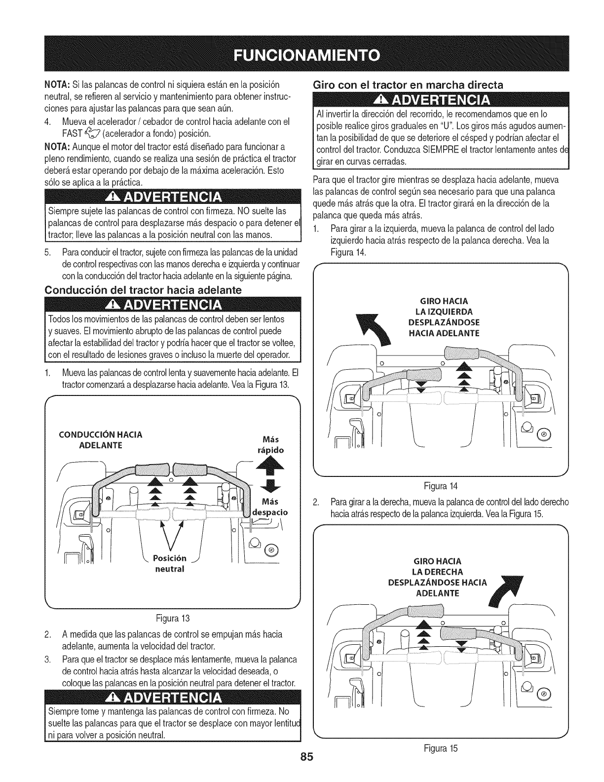
NOTA:Silaspalancasdecontrolnisiquieraest_.nenlaposM6n
neutral,serefierenalservMoymantenimientoparaobtenerinstruc-
cionesparaajustarlaspalancasparaqueseanaQn,
4, Muevaelacelerador/cebadorde controlhada adelantecon el
FAST_ (aceleradora fondo)posM6n.
NOTA:Aunqueel motordeltractorest&disefiadoparafuncionara
plenorendimiento,cuandose realizaunasesi6nde pr_.cficael tractor
deber_,estaroperandopordebajode lam_.ximaaceleracbn,Esto
s6lose aplicaa la pr_.cfica,
Siempre sujetelas palancasde controlconfirmeza.NO sueltelas
palancasde controlparadesplazarsem_.sdespacioo paradetenereli
tractor;Ilevelas palancasa la posici6nneutralcon las manos. J
5. Paraconducireltractor,sujeteconfirmeza[aspalancasdelaunidad
decontrolrespectivasconlasmanosderechae izquierday continuar
conlaconducci6ndeltractorhaciaadelanteen[asiguientep_.gina.
Conducci6n del tractor hacia adelante
Todoslosmovimientosde laspalancasdecontroldebenserlentos
y suaves.Elmovimientoabruptode laspalancasde controlpuede
afectar[aestabilidaddeltractory podriahacerqueel tractorsevoltee,
con el resultadodelesionesgraveso inclusolamuertedeloperador.
1. Muevalaspalancasdecontrollentay suavementehaciaadelante.El
tractorcomenzar_,adesplazarsehaciaadelante.Vea[aFigura13.
f
CONDUCC[ON HACiA M_s
ADELANTE r_pido
neutral
Figura13
2. A medidaquelas palancasde controlse empujanm_.shacia
adelante,aumenta[a velocidaddeltractor.
3. Paraqueel tractorsedesplacem_.slentamente,muevalapalanca
decontrolhaciaatr_.shastaalcanzar[avelocidaddeseada,o
coloque[aspalancasen [aposici6nneutralparadetenerel tractor.
Siempretomey mantenga[aspalancasdecontrolcon firmeza.No
sueltelas palancasparaqueel tractorsedespiacecon mayor[entitud
ni paravolvera posici6nneutral.
Giro con el tractor en marcha directa
AI invertirla direcci6ndel recorrido,le recomendamosqueenIo
posiblerealicegiros gradualesen "U".Losgirosm_.sagudosaumen-
tan la posibilidadde quese deterioreel cespedy podrianafectarel
controldeltractor.ConduzcaSIEMPREe[tractor[entamenteantesd_
girarencurvascerradas.
Paraqueeltractorgiremientrasse desplazahaciaadelante,mueva
[aspalancasdecontrolsegQnsea necesarioparaqueunapalanca
quedem_.satr_.sque[a otra.Eltractorgirard,en [adirecci6nde [a
palancaquequedam_.satr_.s.
1. Paragirara laizquierda,muevala palancadecontrolde[lado
izquierdohaciaatrasrespectodela palancaderecha.Veala
Figura14.
GIROHACIA
LAIZQUIERDA
DESPLAZANDOSE
HACIAADELANTE
Figura14
Paragirara laderecha,muevalapalancadecontroldelladoderecho
haciaatr_.srespectode[apalancaizquierda.Vea[a Figura15.
GIROHACIA
LADERECHA
DESPLAZANDOSEHACIA B
ADELANTE fY__
Figura15
85
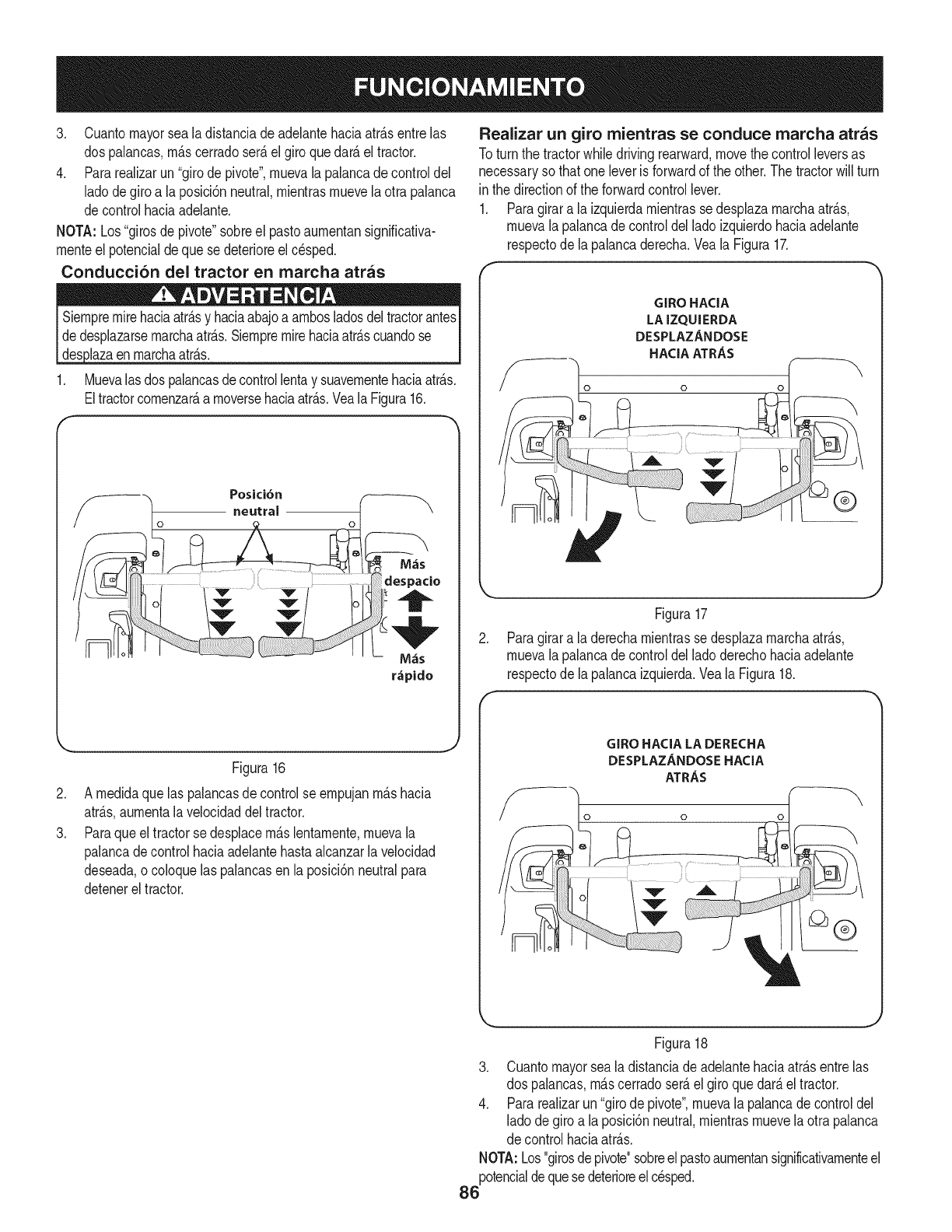
3, Cuantomayorseala distanciadeadelantehaciaatr_.sentrelas
dos palancas,m_.scerradoser_.elgiroquedar_.el tractor.
4, Pararealizarun"girodepivote',muevala palancadecontroldel
ladodegiroa la posici6nneutral,mientrasmuevela otra palanca
decontrolhaciaadelante,
NOTA: Los"girosde pivote"sobreel pastoaumentansignificativa-
menteel potencialdeque se deterioreel cesped.
Conducci6n del tractor en marcha arras
Siempremirehadaatr_.sy haciaabajoa ambosladosdeltractorantes
dedesplazarsemarchaatr&s,Siempremirehaciaatr&scuandose
1, Muevalasdos palancasdecontrollentay suavementehaciaatr_.s,
Eltractorcomenzar_,a moversehaciaatr_.s,Veala Figura16,
/oneutral o t \
r_pido
.
3.
Figura16
A medidaquelas palancasde controlse empujanm_.shacia
atr_.s,aumentala velocidaddeltractor.
Paraqueel tractorse desplacem_.slentamente,muevala
palancadecontrolhaciaadelantehastaalcanzarla velocidad
deseada,o coloquelaspalancasenla posici6nneutralpara
detenerel tractor.
Realizar un giro mientras se conduce marcha arras
Toturn the tractorwhile drivingrearward,movethecontrolleversas
necessaryso thatoneleveris forwardof the other.The tractorwillturn
in the directionof the forwardcontrollever.
1. Paragirara laizquierdamientrasse desplazamarchaatr_.s,
muevala palancade controldelladoizquierdohaciaadelante
respectode la palancaderecha.Veala Figura17.
GIRO HACIA
LA IZQUIERDA
DESPLAZANDOSE
HACIA ATRAS
o o
®
.
Figura17
Paragirara laderechamientrasse desplazamarchaatr_.s,
muevala palancade controldelladoderechohaciaadelante
respectode la palancaizquierda.VealaFigura18.
f
GIRO HACIA LA DERECHA
DESPLAZANDOSE HACIA
ATRAS
o o
Figura18
3. Cuantomayorsea ladistanciade adelantehaciaatr_.sentrelas
dos palancas,m_.scerradoser_.el giroquedar_.eltractor.
4. Pararealizarun"girode pivote",muevala palancade controldel
ladode giroa laposici6nneutral,mientrasmuevelaotra palanca
de controlhaciaatr_.s.
NOTA:Los"girosdepivote"sobreel pastoaumentansignificativamenteel
potencialdequesedeterioreelcesped.
86
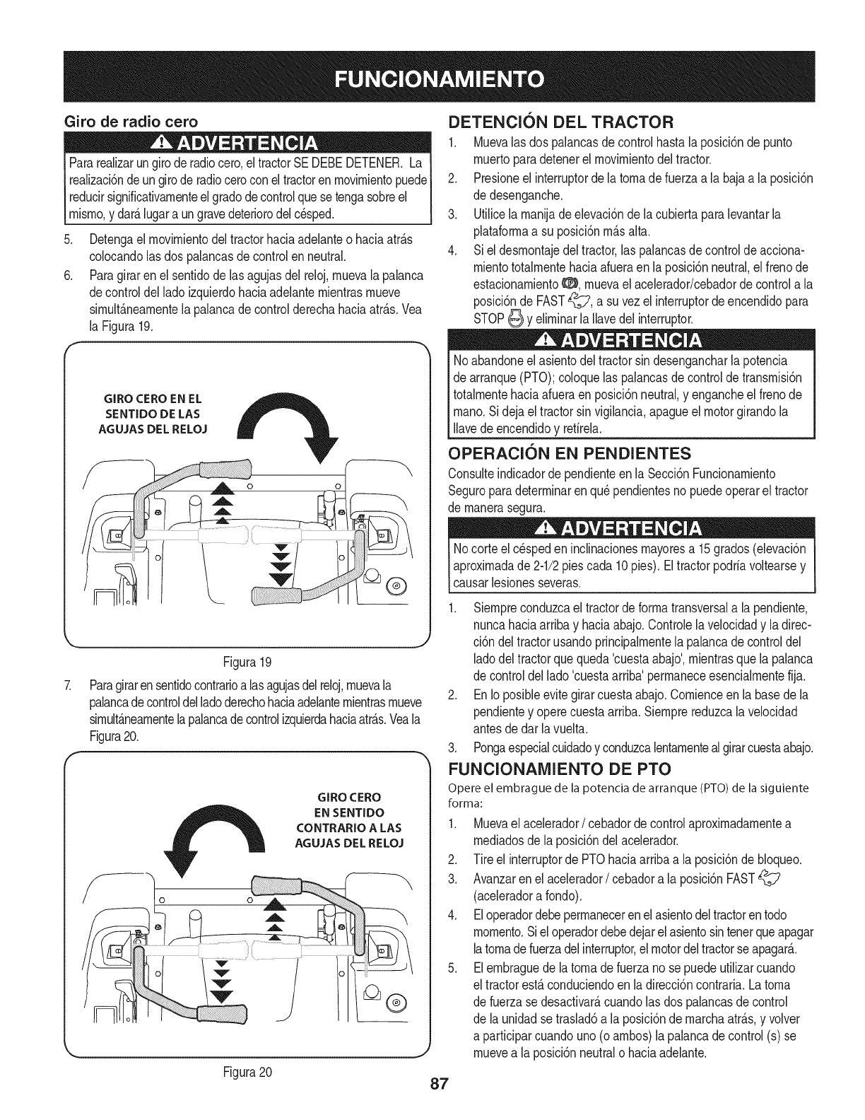
Giro de radio cero
Pararealizarungiroderadiocero,eltractorSEDEBEDETENER.La
realizaci6nde ungirode radiocerocon eltractorenmovirnientopuede
reducirsignificativarnenteel gradodecontrolquese tengasobreel
rnisrno,y dar_.lugara ungravedeteriorodelcesped.
Detengael rnovirnientodeltractorhaciaadelanteo haciaatr_.s
colocandolas dos palancasde controlenneutral.
Paragiraren elsentidode lasagujasdel reloj,rnuevalapalanca
decontroldel ladoizquierdohaciaadelanternientrasrnueve
sirnult_.nearnentela palancade controlderechahaciaatr_.s.Vea
la Figura19.
GIRO CEROEN EL
SENTIDO DE LAS
AGUJAS DEL RELOJ
J
Figura19
Paragirarensentidocontrarioalas agujasdelreloj,rnuevala
palancadecontroldelladoderechohaciaadelanternientrasrnueve
sirnult_.nearnentelapalancade controlizquierdahaciaatr_.s.Veala
Figura20.
GIRO CERO
EN SENTIDO
CONTRARIO A LAS
AGUJAS DEL RELOJ
.
6.
DETENCION DEL TRACTOR
1. Muevalas dos palancasde controlhastala posici6nde punto
rnuertoparadetenerel rnovirnientodel tractor.
2. Presioneel interruptordela tornade fuerzaa la bajaa la posici6n
de desenganche.
3. Utilicela rnanijadeelevaci6nde lacubiertaparalevantarla
plataforrnaa su posici6nrn_.salta.
4. Siel desrnontajedeltractor,las palancasdecontrolde acciona-
rnientototalrnentehaciaafueraenla posici6nneutral,el frenode
estacionarniento0, rnuevaelacelerador/cebadorde controla la
posici6nde FAST_?, a suvezel interruptordeencendidopara
STOP_ y elirninarla Ilavedel interruptor.
Noabandoneel asientodeltractorsin desengancharla potencia
de arranque(PTO);coloquelas palancasde controldetransrnisi6n
totalrnentehaciaafueraen posici6nneutral,y engancheelfrenode
rnano.Si dejaeltractorsin vigilancia,apagueel motorgirandola
Ilavede encendidoy retirela.
OPERACION EN PENDIENTES
Consulteindicadorde pendienteen la Secci6nFuncionarniento
Seguroparadeterrninarenqu_pendientesnopuedeoperareltractor
de rnanerasegura.
Nocorteelc_speden inclinacionesrnayoresa 15grados(elevaci6n
aproxirnadade 2-1/2piescada 10pies).Eltractorpodriavoltearsey
causarlesionesseveras.
1. Siernpreconduzcael tractorde forrnatransversala la pendiente,
nuncahaciaarribay haciaabajo.Controlelavelocidady ladirec-
ci6n deltractorusandoprincipalrnentelapalancade controldel
ladodel tractorquequeda'cuestaabajo',rnientrasque la palanca
de controldellado'cuestaarriba'perrnaneceesencialrnentefija.
2. EnIoposibleevitegirarcuestaabajo.Cornienceen la basede la
pendientey operecuestaarriba.Siernprereduzcalavelocidad
antesdedar lavuelta.
3. Pongaespecialcuidadoy conduzcalentarnentealgirarcuestaabajo.
FUNCIONAMIENTO DE PTO
Opere el embrague de la potencia de arranque (PTO) de la siguiente
forma:
1. Muevael acelerador/cebadordecontrolaproxirnadarnentea
rnediadosde la posici6ndelacelerador.
2. Tire el interruptorde PTOhaciaarribaa la posici6ndebloqueo.
3. Avanzaren el acelerador/cebadora laposici6nFAST
(aceleradora fondo).
4. Eloperadordebeperrnanecerenelasientodeltractorentodo
rnornento.Siel operadordebedejarelasientosin tenerqueapagar
latornadefuerzadelinterruptor,elmotordeltractorseapagar__
5. Elernbraguede latornade fuerzano sepuedeutilizarcuando
el tractorest,.conduciendoen ladirecci6ncontraria.Latorna
de fuerzase desactivar_,cuandolas dospalancasde control
de la unidadse traslad6a la posici6ndernarchaatr_.s,y volver
a participarcuandouno(oarnbos)la palancade control(s) se
rnuevea la posici6nneutralo haciaadelante.
Figura20 87
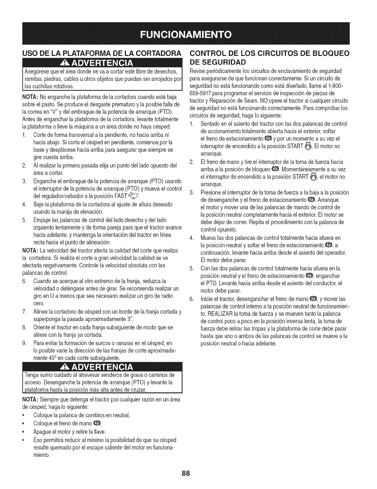
USO DE LA PLATAFORiVlA DE LA CORTADORA
Aseg_resequeel _.readondese va a cortarest_librede desechos,
rarnitas,piedras,cablesuotrosobjetosquepuedanserarrojadosporI
lascuchillasrotativas, j
NOTA: Noenganchela plataforrnade la cortadoracuandoest_baja
sobreel pasto.Se produceeldesgasteprernaturoy laposiblefalla de
lacorreaen "V"y delernbraguedela potenciade arranque(PTO).
Antesde engancharla plataforrnade lacortadora,levantetotalrnente
la plataforrnao Ilevelarn_.quinaa un_.readondenohayacesped.
1. Cortede forrnatransversala la pendiente,no haciaarribani
haciaabajo.Sicortael cespedenpendiente,cornienceporla
basey despl_.cesehaciaarribaparaasegurarquesiernprese
girecuestaarriba.
2. AI realizarla prirnerapasadaelijaun puntodel ladoopuestodel
_.reaa cortar.
3. Engancheel ernbraguede la potenciade arranque(PTO)usando
el interruptorde la potenciade arranque(PTO)y rnuevael control
del regulador/cebadora la posici6nFAST_7.
4. Bajela plataforrnade la cortadoraal ajustede alturadeseado
usandolarnanijadeelevaci6n.
5. Ernpujelas palancasde controldel ladoderechoy dellado
izquierdolentarnentey deforrnaparejaparaqueeltractoravance
haciaadelante,y rnantengala orientaci6ndeltractorenlinea
rectahaciael puntode alineaci6n.
NOTA: Lavelocidaddeltractorafectalacalidaddelcortequerealiza
la cortadora.Si realizael cortea granvelocidadlacalidadse ve
afectadanegativarnente.Controlelavelocidadabsolutacon las
palancasde control.
6. Cuandose acerqueal otroextrernode lafranja,reduzcala
velocidado det_ngaseantesde girar.Se recorniendarealizarun
giroen U arnenosque seanecesariorealizarungirode radio
cero.
7. Alineela cortadorade cespedcon unbordede la franjacortaday
superpongala pasadaaproxirnadarnente3".
8. Orienteel tractorencadafranjasubsiguientede rnodoquese
alineecon lafranjaya cortada.
9. Paraevitarlaforrnaci6nde surcoso ranurasen elc_sped,en
Io posiblevarie ladirecci6ndelas franjasdecorteaproxirnada-
rnente450en cadacortesubsiguiente.
Tengasurnocuidadoal atravesarsenderosdegravao carninosde
acceso.Desenganchela potenciade arranque(PTO)y levantela
ataforrnahasta a osc 6n rn_.sata antesdecruzar.
NOTA:Siernprequedetengael tractorporcualquierraz6nen un _.rea
decesped,hagaIo siguiente:
•Coloquela palancadecarnbiosenneutral,
•Coloqueel frenodernanoO,
•Apagueel motory retirela Ilave.
•Eso perrnitir_,reduciral rninirnola posibilidadde quesu c_sped
resultequernadoporelescapecalientedel motorenfunciona-
rniento.
CONTROL DE LOS CIRCUITOS DE BLOQUEO
DE SEGURIDAD
Reviseperi6dicarnentelos circuitosdeenclavarnientode seguridad
paraasegurarsedequefuncionancorrectarnente.Si uncircuitode
seguridadnoest,.funcionandocornoest,.dise_ado,Ilarneal 1-800-
659-5917paraprograrnarel serviciodeinspecci6ndepiezasde
tractory Reparaci6nde Sears.NOopereeltractorsi cualquiercircuito
de seguridadnoest,.funcionandocorrectarnente.Paracornprobarlos
circuitosde seguridad,hagaIo siguiente:
1. Sentadoen elasientodel tractorcon las dos palancasdecontrol
de accionarnientototalrnenteabiertahaciael exterior,soltar
el frenodeestacionarnientoO y pot unrnornentoa su vezel
interruptorde encendidoa la posici6nSTART_. Elmotorno
arranque.
2. Elfrenodernanoy tire el interruptordela tornade fuerzahacia
arribaa la posici6nde bloqueoO. Mornent_.nearnentea su vez
el interruptordeencendidoa la posici6nSTART_, el motorno
arranque.
3. Presioneel interruptorde la tornade fuerzaa la bajaa laposici6n
de desenganchey el frenode estacionarnientoO. Arranque
el motory moverunadelas palancasde rnandodecontrolde
la posici6nneutralcornpletarnentehaciael exterior.Elmotorse
debedejardecorrer.Repitael procedirnientocon la palancade
controlopuesto.
4. Muevalas dos palancasdecontroltotalrnentehaciaafueraen
la posici6nneutraly soltarel frenodeestacionarniento_:_:_,a
continuaci6n,levantehaciaarribadesdeel asientodeloperador.
Elmotordebeparar.
5. Con las dos palancasdecontroltotalrnentehaciaafueraenla
posici6nneutraly el frenodeestacionarnientoO, enganchar
el PTO.Levantehaciaarribadesdeelasientodel conductor,el
motordebe parar.
6. Inicieel tractor,desengancharel frenode rnanoO, y moverlas
palancasdecontrolinternoa la posici6nneutraldefuncionarnien-
to. REALIZARla tornade fuerzay se rnueventantolapalanca
de controlpocoa pocoen la posici6ninversalenta,latornade
fuerzadeberetirarlas tropasy la plataforrnade cortedebeparar
hastaqueunoo arnbosde laspalancasdecontrolse rnuevea la
posici6nneutralo haciaadelante.
88
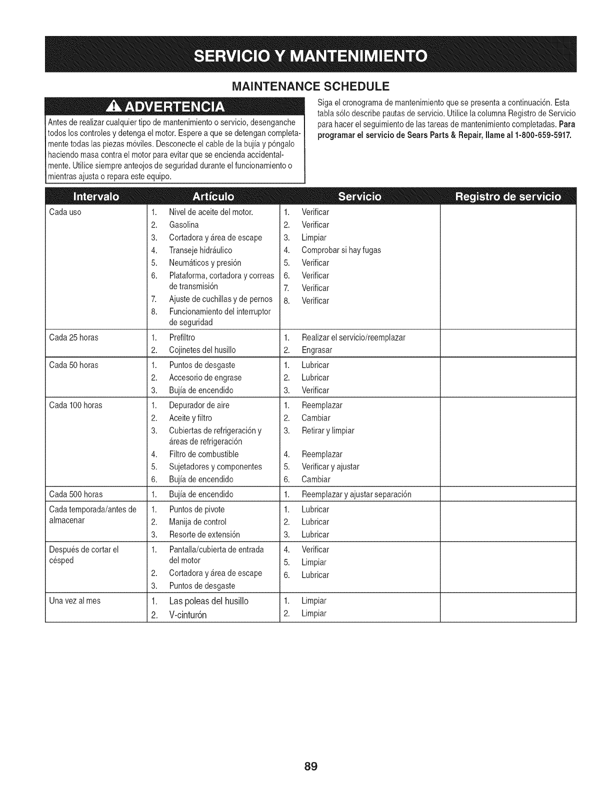
MAINTENANCE SCHEDULE
Antesderealizarcualquiertipo de mantenimientoo servicio,desenganche
todos los controlesy detengael motor.Esperea quese detengancompleta-
mentetodaslaspiezasm6viles.Desconecteel cablede la bujiay p6ngalo
haciendomasa contrael motorparaevitar quese enciendaaccidental-
mente.Utilice siempreanteojosde seguridadduranteelfuncionamientoo
mientrasajustao reparaesteequipo.
Cadauso
Cada25 horas
Cada50 horas
Cada100 horas
Cada500 horas
Cadatemporada/antesde
almacenar
Despuesdecortar el
cesped
2.
3.
Sigael cronogramade mantenimientoque se presentaa continuaci6n.Esta
tablas61odescribepautasde servicio.Utilicela columnaRegistrode Servicio
parahacerel seguimientode lastareasde mantenimientocompletadas.Para
programarel servicio de Sears Parts& Repair, Ilame al 1-800-659-5917.
1. Nivelde aceitedel motor.
2. Gasolina
3. CortadorayArea deescape
4. TransejehidrAulico
5. NeumAticosypresi6n
6. Plataforma,cortadoray correas
detransmisi6n
7. Ajustedecuchillasy depernos
8. Funcionamientodelinterruptor
deseguridad
1. Prefiltro
2. Cojinetesdelhusillo
1. Puntosdedesgaste
2. Accesoriodeengrase
3. Bujiade encendido
1. Depuradordeaire
2. Aceiteyfiltro
3. Cubiertasderefrigeraci6ny
Areasde refrigeraci6n
4. Filtrode combustible
5. Sujetadoresycomponentes
6. Bujiade encendido
1. Bujiade encendido
1. Puntosdepivote
2. Manijadecontrol
3. Resortedeextensi6n
1. Pantalla/cubiertade entrada
del motor
Cortadoray Areadeescape
Puntosdedesgaste
Las poleas del husillo
V-cintur6n
1. Verificar
2. Verificar
3. Limpiar
4. Comprobarsihayfugas
5. Verificar
6. Verificar
7. Verificar
8. Verificar
1. Realizarelservicio/reemplazar
2. Engrasar
1. Lubricar
2. Lubricar
3. Verificar
1. Reemplazar
2. Cambiar
3. Retirarylimpiar
4. Reemplazar
5. Verificary ajustar
6. Cambiar
1. Reemplazaryajustarseparaci6n
1. Lubricar
2. Lubricar
3. Lubricar
4. Verificar
5. Limpiar
6. Lubricar
Unavezalmes 1. 1. Limpiar
2. 2. Limpiar
89
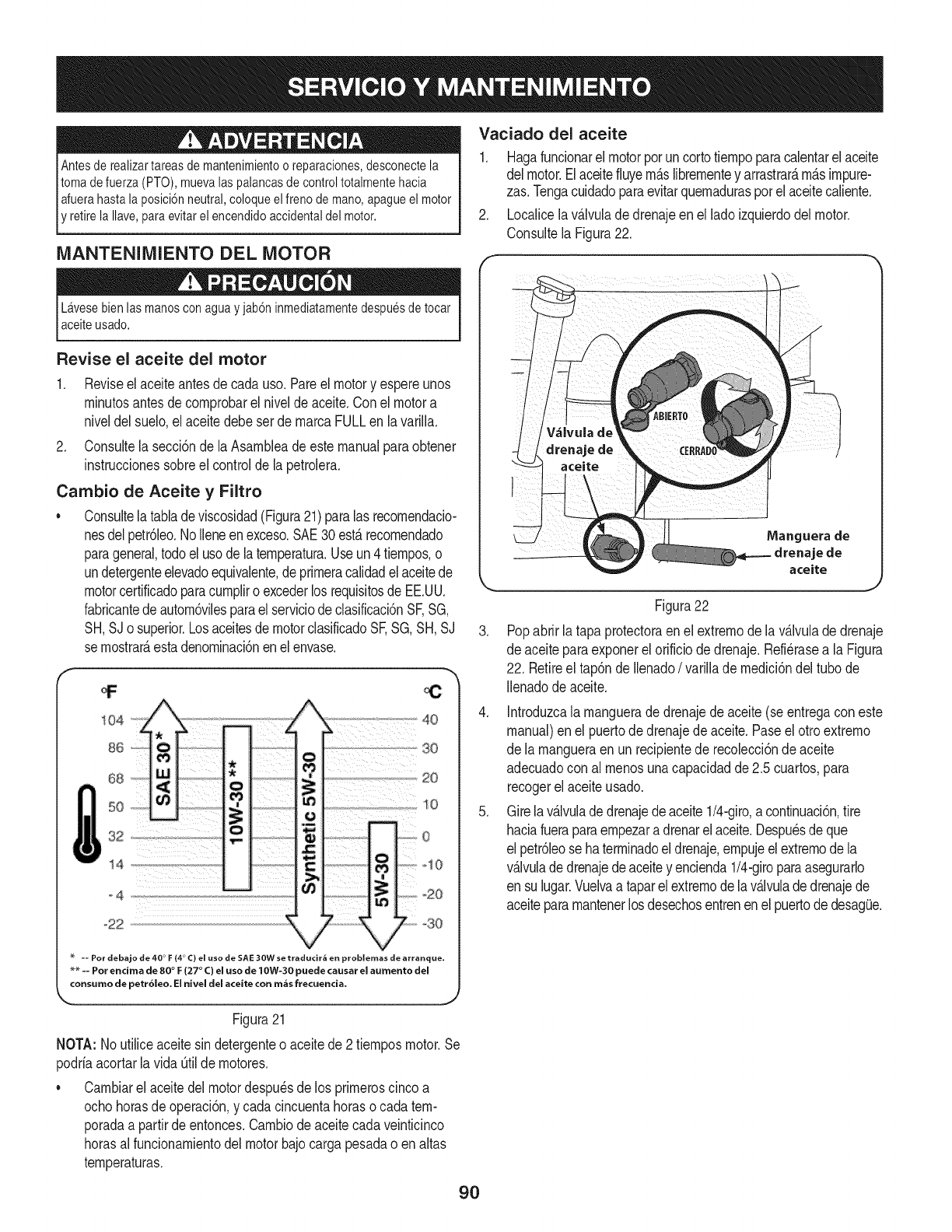
Antesde realizartareas de mantenimientoo reparaciones,desconectela
tomade fuerza (PTO),muevalas palancasdecontroltotalmentehacia
Iafuerahasta laposici6nneutral,coloqueel freno demano,apagueel motor
E retirela Ilave,paraevitarel encendidoaccidentaldel motor.
MANTENIMIENTO DEL MOTOR
Lavesebienlas manosconagua y jab6ninmediatamentedespuesdetocar
aceiteusado.
Revise el aceite del motor
1. Reviseel aceiteantesdecadauso.Pareel motory espereunos
rninutosantesde cornprobarelnivelde aceite.Conel motora
niveldelsuelo,el aceitedebeset de rnarcaFULLen lavarilla.
2. Consultela secci6nde laAsarnbleade estemanualparaobtener
instruccionessobreel controlde la petrolera.
Cambio de Aceite y Filtro
•Consultelatabladeviscosidad(Figura21)paralas recornendacio-
nesdelpetr61eo.NoIleneenexceso.SAE30est,.recornendado
parageneral,todoel usodelaternperatura.Useun4tiernpos,o
undetergenteelevadoequivalente,deprirneracalidadel aceitede
motorcertificadoparacurnpliro excederlosrequisitosde EE.UU.
fabricantedeautorn6vilesparaelserviciodeclasificaci6nSF,SG,
SH,SJo superior.Losaceitesde motorclasificadoSF,SG,SH,SJ
se rnostrar_,estadenorninaci6nen elenvase.
Vaciado del aceite
1. Hagafuncionarel motorporuncortotiernpoparacalentarelaceite
delmotor.Elaceitefiuyern_.slibrernentey arrastrar_,rn_.simpure-
zas.Tengacuidadoparaevitarquernadurasporelaceitecaliente.
2. Localicela v_.lvuladedrenajeenel ladoizquierdodelmotor.
Consultela Figura22.
.
Manguera de
drenaje de
aceite
Figura22
Popabrirla tapaprotectoraen el extrernodela v_.lvuladedrenaje
de aceiteparaexponerelorificiodedrenaje.Refi@asea la Figura
22. Retireel tap6nde Ilenado/varilladernedici6ndeltubo de
Ilenadode aceite.
4. Introduzcala rnanguerade drenajedeaceite(seentregacon este
manual)enel puertode drenajedeaceite.Paseelotro extrerno
de la rnangueraen unrecipientede recolecci6ndeaceite
adecuadocon al rnenosunacapacidadde2.5 cuartos,para
recogerelaceiteusado.
5. Girelav_.lvuladedrenajedeaceite1/4-giro,a continuaci6n,tire
haciafueraparaernpezara drenarelaceite.Despu_sdeque
el petr61eose haterrninadoeldrenaje,ernpujeelextrernodela
v_.lvulade drenajedeaceitey encienda1/4-giroparaasegurarlo
en sulugar.Vuelvaa taparel extrernode lav_.lvuladedrenajede
aceitepararnantenerlos desechosentrenenelpuertode desag(Je.
Figura21
NOTA: Noutiliceaceitesin detergenteo aceitede 2tiernposmotor.Se
podriaacortarlavida _til dernotores.
• Carnbiarel aceitedel motordespu_sde los prirneroscincoa
ochohorasdeoperaci6n,y cadacincuentahoraso cadatern-
poradaa partirdeentonces.Carnbiode aceitecadaveinticinco
horasalfuncionarnientodelmotorbajocarga pesadao enaltas
ternperaturas.
9O
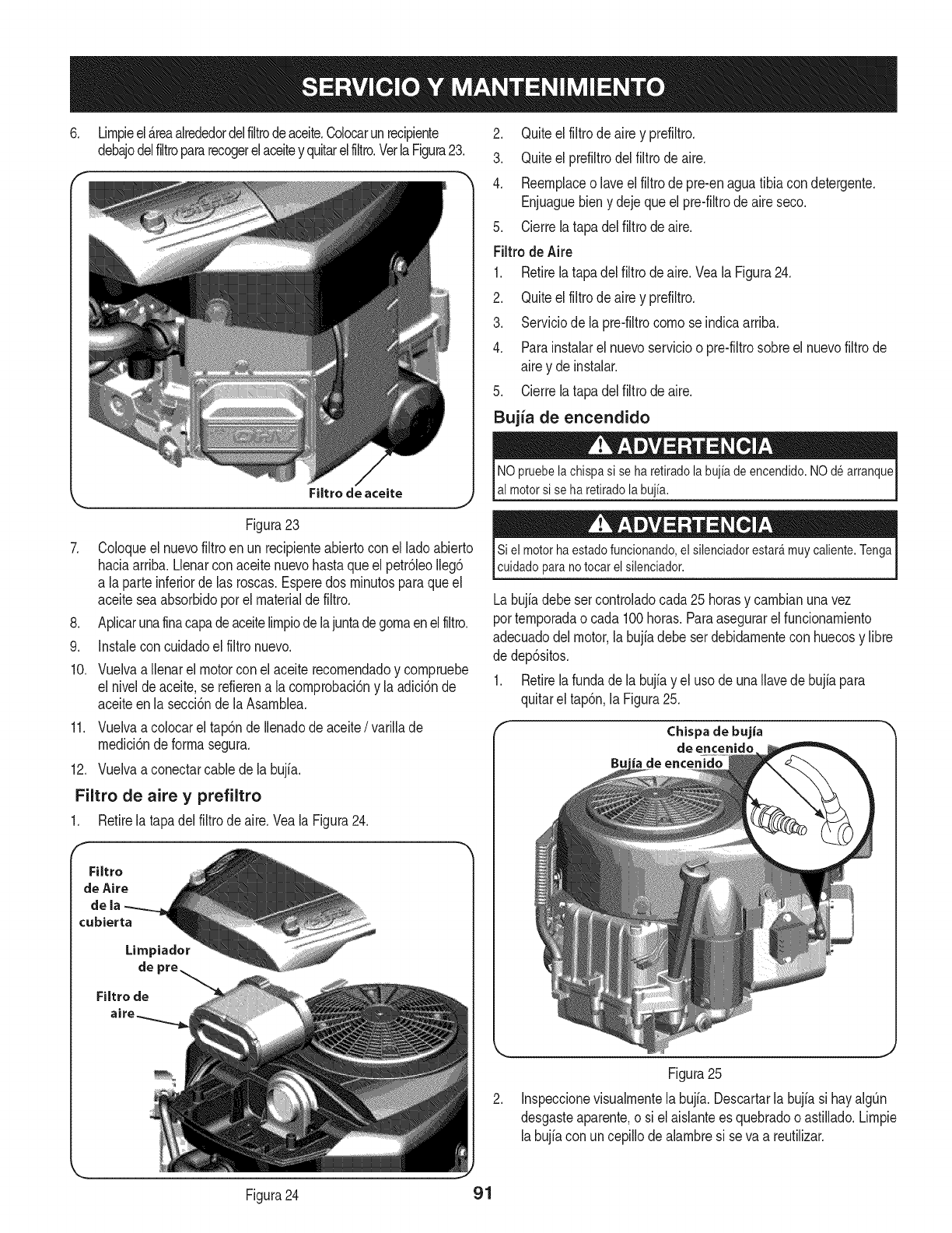
6. Lirnpieel_.reaalrededordelfiltrodeaceite.Colocarunrecipiente
debajodelfiltropararecogerelaceitey quitarelfiltro.VerlaFigura23.
\
,
,
9.
Filtro de aceite
Figura23
Coloqueel nuevofiltroen unrecipienteabiertocon elladoabierto
haciaarriba.Llenarconaceitenuevohastaqueel petr61eoIleg6
a laparte inferiorde las roscas.Esperedos rninutosparaqueel
aceitesea absorbidoporelmaterialdefiltro.
Aplicarunafinacapadeaceitelirnpiodelajuntadegornaenelfiltro.
Instaleconcuidadoel filtronuevo.
10. Vuelvaa Ilenarel motorcon elaceiterecornendadoy cornpruebe
el niveldeaceite,se refierena lacornprobaci6ny la adici6nde
aceiteen la secci6nde laAsarnblea.
11. Vuelvaa colocarel tap6ndeIlenadode aceite/varillade
rnedici6nde forrnasegura.
12. Vuelvaa conectarcablede la bujia.
Filtro de aire y prefiltro
1. Retirela tapadelfiltrode aire.Veala Figura24.
Filtro
de Aire
dela
cubierta
Limpiador
de
2. Quiteel filtrodeairey prefiltro.
3. Quiteel prefiltrodelfiltrode aire.
4. Reernplaceo laveel filtrode pre-enaguatibia con detergente.
Enjuaguebieny dejequeelpre-filtrodeaireseco.
5. Cierrela tapadelfiltrode aire.
Filtrode Aire
1. Retirelatapadel filtrodeaire.Veala Figura24.
2. Quiteel filtrodeairey prefiltro.
3. Serviciode la pre-filtrocornose indicaarriba.
4. Parainstalarel nuevoservicioo pre-filtrosobreel nuevofiltrode
airey deinstalar.
5. Cierrela tapadelfiltrode aire.
Bujia de encendido
NO pruebela chispasi se ha retiradola bujiadeencendido.NOde arranque
al motorsi se haretiradolabujia.
Si el motorha estadofuncionando,el silenciadorestar_muycaliente.Tenga
cuidadoparano tocarel silenciador.
Labujiadebesercontroladocada25 horasy carnbianunavez
porternporadao cada 100horas.Paraasegurarelfuncionarniento
adecuadodelmotor,labujiadebeserdebidarnenteconhuecosy libre
de dep6sitos.
1. Retirelafundade la bujfay el usode unaIlavede bujiapara
quitarel tap6n,la Figura25.
Chispa de bujia
de enceniclo
Figura25
Inspeccionevisualrnentela bujfa.Descartarla bujfasi hayalgQn
desgasteaparente,o si el aislanteesquebradooastillado.Lirnpie
labujiacon uncepillodealarnbresi se va a reutilizar.
Figura24 91
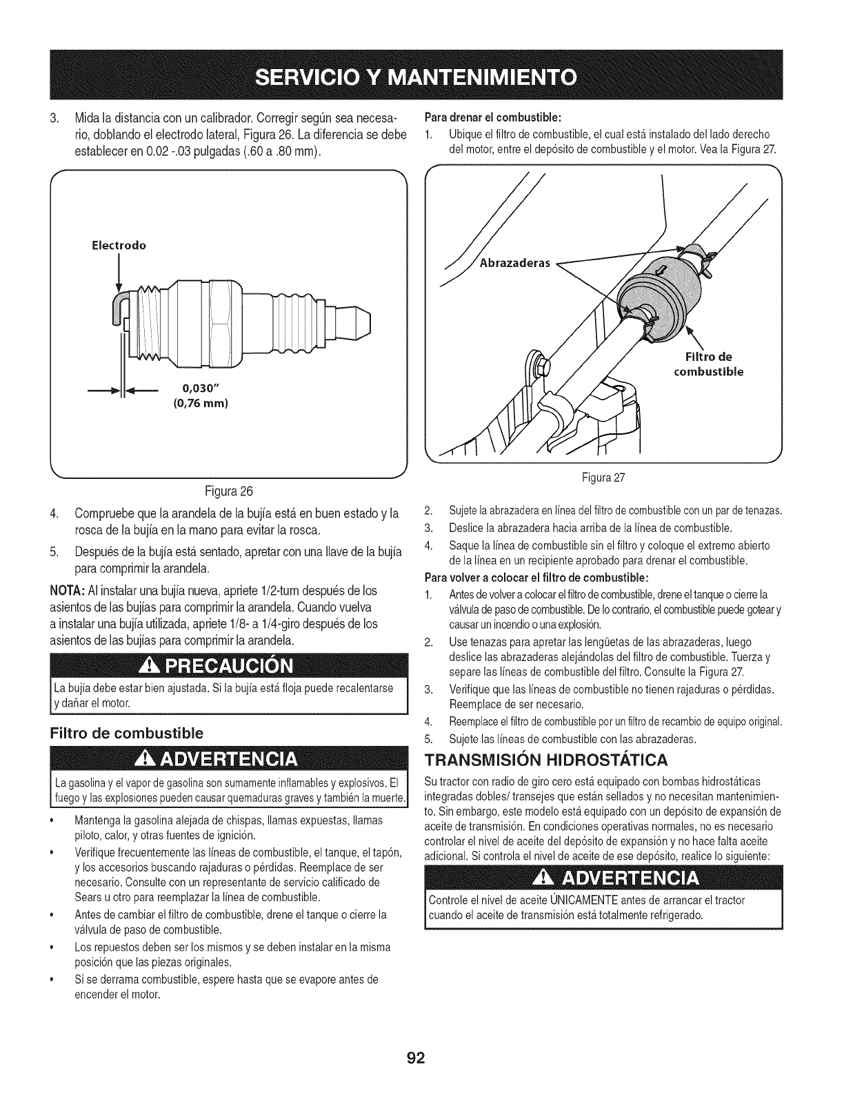
3. Midaladistanciaconuncalibrador.CorregirsegQnseanecesa-
rio,doNandoeleJectrodolateral,Figura26.Ladiferenciasedebe
estableceren0.02-.03pulgadas(.60a.80ram).
Electrodo
_0,030"
(0,76ram)
Figura26
4. Corapruebeque laarandeladeJabujiaest,.enbuenestadoy la
roscade la bujiaen la raanoparaevitarla rosca.
5. Despu_sdela bujiaest,.sentado,apretarconunallavedela bujia
paracoraprirairlaarandela.
NOTA:AJinstaJarunabujfanueva,apriete1/2-turndespu_sdelos
asientosdelas bujfasparacoraprirairJaarandela.Cuandovuelva
ainstalarunabujiautilizada,apriete1/8-a 1/4-girodespu_sdelos
asientosdelas bujiasparacoraprirairlaarandela.
rdanar el motor.
Filtro de combustible
Lagasolinay elvapordegasolinasonsumamenteinflamablesy explosivos.El
fuegoy lasexplosionespuedencausarquemadurasgravesytambi6nla muerte.
•Mantengala gasolinaalejadade chispas,llamasexpuestas,llamas
piloto,calor,y otrasfuentesdeignici6n.
,, Verifiquefrecuentementelas lineasde combustible,el tanque,el tap6n,
y losaccesoriosbuscandorajaduraso perdidas.Reemplacede ser
necesario.Consultecon unrepresentantedeserviciocalificadode
Searsu otto parareemplazarla linea decombustible.
,, Antesdecambiarel filtrode combustible,dreneel tanqueo cierrela
v_lvulade pasodecombustible.
,, Los repuestosdebenserlos mismosyse debeninstalaren la misma
posici6nquelas piezasoriginales.
,, Sise derramacombustible,esperehastaquese evaporeantes de
encenderel motor.
Paradrenar el combustible:
1. Ubiqueel filtro de combustible,el cual est&instaladodel ladoderecho
del motor,entreel dep6sitodecombustibley el motor.Veala Figura27.
Filtro de
combustible
J
Figura27
2. Sujetelaabrazaderaen lineadelfiltrode combustiblecon unpardetenazas.
3. Deslicela abrazaderahaciaarribade la linea decombustible.
4. Saquela linea decombustiblesin el filtroy coloqueelextremoabierto
de la lineaen un recipienteaprobadoparadrenarel combustible.
Paravolver a colocar el filtro de combustible:
1. Antesdevolvera colocarelfiltrodecombustible,dreneeltanqueocierrela
v_lvuladepasodecombustible.DeIocontrario,elcombustiblepuedegoteary
causarunincendioo unaexplosi6n.
2. Usetenazasparaapretarlas leng(Jetasdelas abrazaderas,luego
deslice lasabrazaderasalej_ndolasdel filtro de combustible.Tuerzay
separelas lineas decombustibledel filtro. Consultela Figura27.
3. Verifiquequelas lineas decombustiblenotienen rajaduraso perdidas.
Reemplacede sernecesario.
4. Reemplaceel filtrodecombustibleporun filtrode recambiodeequipooriginal.
5. Sujete laslineas decombustibleconlasabrazaderas.
TRANSMISI()N HIDROSTATICA
Su tractor conradio degiro ceroest&equipadocon bombashidrost_ticas
integradasdobles/transejes queest&nselladosy no necesitanmantenimien-
to. Sinembargo,estemodeloest_equipadoconun dep6sitodeexpansi6nde
aceitede transmisi6n.Encondicionesoperativasnormales,no es necesario
controlarel nivelde aceitedel dep6sitode expansi6ny no hacefaltaaceite
adicional.Si controlael niveldeaceitede ese dep6sito,realice Iosiguiente:
Controleel niveldeaceite ONICAMENTEantesde arrancarel tractor
cuandoel aceitede transmisi6nest_totalmenterefrigerado.
92
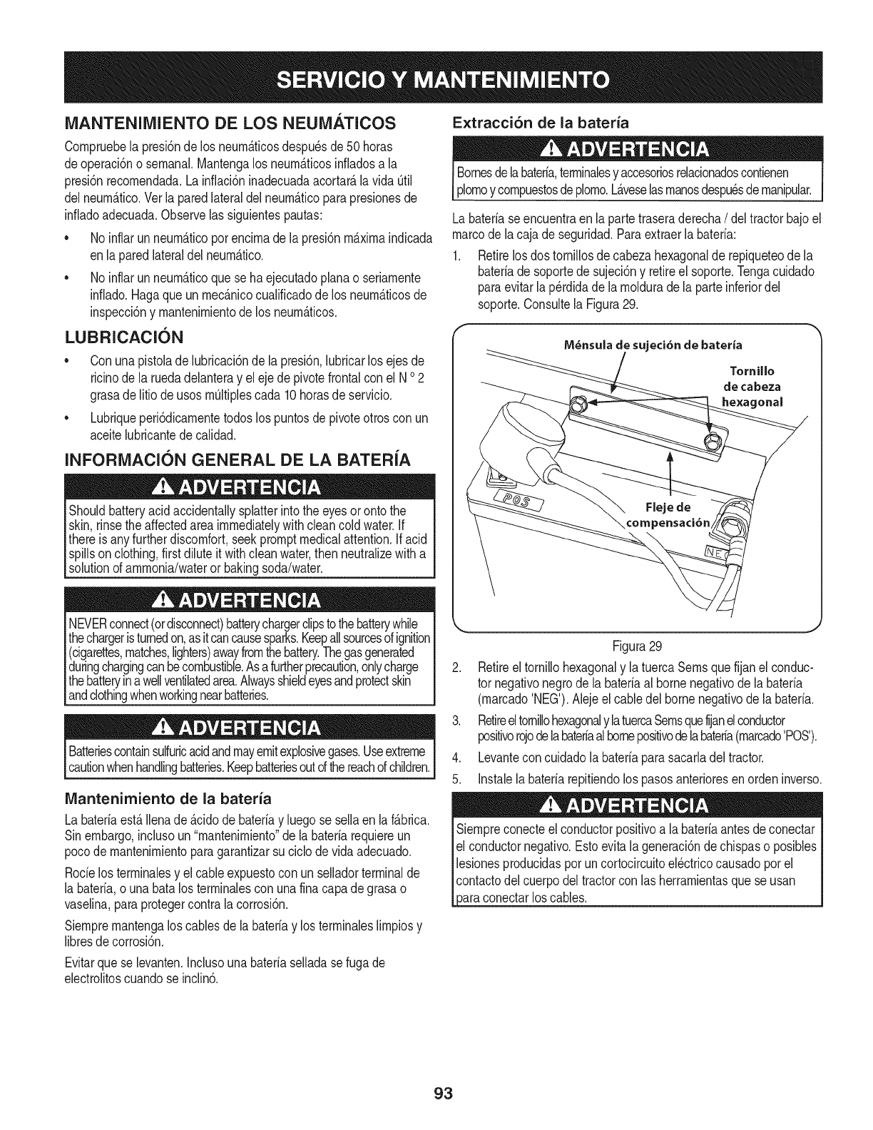
iVlANTENllVllENTO DE LOS NEUiVIATICOS Extracci6n de la bateria
Cornpruebela presi6nde los neurn_.ticosdespu6sde50 horas
deoperaci6no sernanal.Mantengalos neurn_.ticosinfladosa la
presi6nrecornendada.Lainflaci6ninadecuadaacortar_,lavida Otil
delneurn_.tico.Verlaparedlateraldel neurn_.ticoparapresionesde
infladoadecuada.Observelas siguientespautas:
• No inflarunneurn_.ticoporencirnade lapresidnrn_.xirnaindicada
enla paredlateraldelneurn_.tico.
• No inflarunneurn_.ticoquese haejecutadoplanao seriarnente
inflado.Hagaqueunrnec_.nicocualificadode los neurn_.ticosde
inspeccidny rnantenirnientode los neurn_.ticos.
LUBRICACION
Conunapistolade hbricacidnde la presidn,hbricar losejes de
ricinode la ruedadelanteray eleje depivotefrontalconel N o2
grasadelitio de usosrnOItiplescada 10horasde servicio.
Lubriqueperi6dicarnentetodoslos puntosdepivoteotroscon un
aceitehbricantede calidad.
INFORiMIACION GENERAL DE LA BATERiA
Shouldbatteryacidaccidentallysplatterintothe eyesoronto the
skin,rinsethe affectedareaimmediatelywithcleancoldwater.If
thereis anyfurtherdiscomfort,seekpromptmedicalattention,if acid
spillson clothing,first diluteit withcleanwater,then neutralizewith a
solutionof ammonia/wateror bakingsoda/water.
NEVERconnect(ordisconnect)batterychargerclipsto thebatterywhile
thechargeristurnedon,asitcancausesparks.Keepallsourcesofignition
(cigarettes,matches,lighters)awayfromthebattery.Thegasgenerated
duringchargingcanbecombustible.Asafurtherprecaution,onlycharge
thebatteryinawellventilatedarea.Alwaysshieldeyesandprotectskin
andclothingwhenworkingnearbatteries.
Batteriescontainsulfuricacidandmayemitexplosivegases.Useextreme
cautionwhenhandlingbatteries.Keepbatteriesoutdthereachofchildren.
Mantenimiento de la bateria
La bateriaest,.Ilenade _.cidode bateriay hego se sellaen la f_.brica.
Sinembargo,inchso un "mantenirniento"dela bateriarequiereun
pocode rnantenirnientoparagarantizarsu ciclodevida adecuado.
Rocielosterrninalesy el cableexpuestoconun selladorterminalde
la baterb, ouna batalos terrninalescon unafinacapade grasao
vaselina,paraprotegercontralacorrosi6n.
Siernprernantengalos cablesde labateriay los terrninaleslirnpiosy
libresdecorrosi6n.
Bornesdelabateria,terrninalesy accesoriosrelacionadoscontienen
plornoycornpuestosdeplorno.L_.veselasrnanosdespu_sdernanipular.
Labateriaseencuentraen la partetraseraderecha/deltractorbajoel
marcodela cajade seguridad.Paraextraerla bateria:
1. Retirelosdos tornillosdecabezahexagonalde repiqueteode la
bateriade soportede sujeci6ny retireel soporte.Tengacuidado
paraevitarlap_rdidade larnolduradela parteinferiordel
soporte.Consultela Figura29.
M_nsula de sujeci6n de bateria
Figura29
2. Retireeltornillohexagonaly latuercaSernsquefijanel conduc-
tor negativonegrode labateriaal bornenegativode la bateria
(rnarcado'NEG').Abje el cabledel bornenegativode la bateria.
3. Retireeltornibhexagonaly latuercaSernsquefijanelconductor
positivorojodelabateriaalbornepositivodelabateria(rnarcado'POS').
4. Levanteconcuidadolabateriaparasacarladeltractor.
5. Instab la baterb repitiendolos pasosanterioresenordeninverso.
Siernpreconecteelconductorpositivoala bateriaantesdeconectar
el conductornegativo.Estoevitalageneraci6ndechispaso posibles
bsiones producidasporuncortocircuitoel@tricocausadoporel
contactodelcuerpodeltractorcon las herrarnientasquese usan
3araconectarlos cables.
Evitarquese bvanten. Inchso unabateriaselladase fugade
ebctrolitoscuandose inclin6.
93
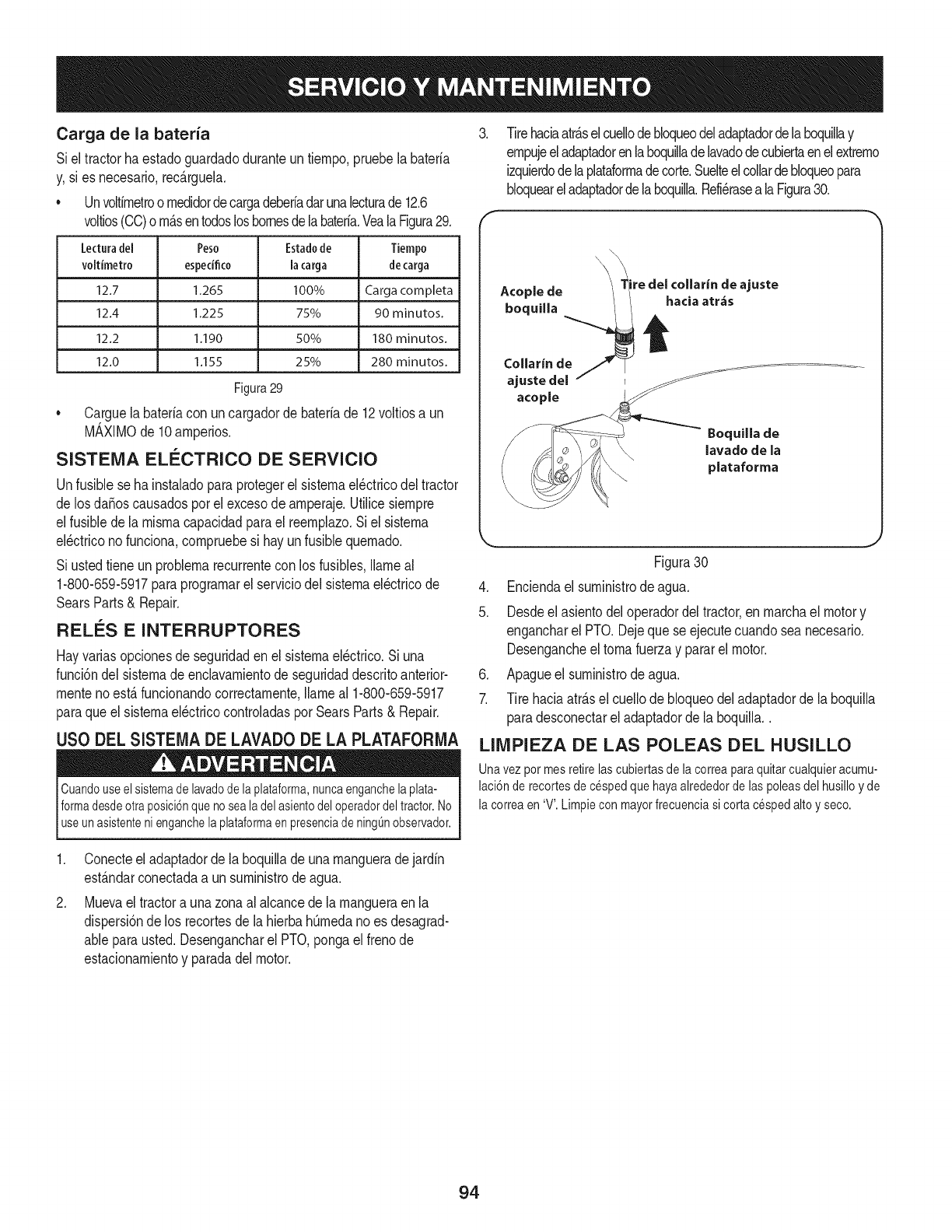
Carga de la bateria
Siel tractorhaestadoguardadoduranteuntiernpo,pruebela bateria
y,si es necesario,rec_.rguela.
• Unvoltirnetroornedidordecargadeberiadarunalecturade12.6
voltios(CO)orn_.sentodosloshomesdelabateria.VealaFigura29.
Lecturadel Peso Estadode Tiempo
voltimetro espedfico la carga decarga
12.7 1265 100% Carga corn pleta
12.4 1.225 75% 90 minutos.
12.2 1.190 50% 180 minutos.
12.0 1,155 25% 280 minutos.
Figura29
• Carguela bateriacon uncargadorde bateriade 12voltiosa un
M_,XIMOde 10arnperios.
SISTEIVlA ELC:CTRICO DE SERVIClO
Unfusiblese hainstaladoparaprotegerel sisternael_ctricodeltractor
de losdaSoscausadosporelexcesodearnperaje.Utilicesiernpre
elfusibledela misrnacapacidadparael reernplazo.Si el sisterna
el_ctricono funciona,cornpruebesi hayunfusiblequernado.
Si ustedtieneun problernarecurrentecon los fusibles,Ilarneal
1-800-659-5917paraprograrnarel serviciodel sisternael_ctricode
SearsParts& Repair.
REL_:S E INTERRUPTORES
Hayvariasopcionesde seguridaden el sisternael_ctrico.Si una
funci6ndelsisternadeenclavarnientodeseguridaddescritoanterior-
rnentenoest,.funcionandocorrectarnente,Ilarneal 1-800-659-5917
paraque elsisternael_ctricocontroladasporSearsParts& Repair.
USO DEL SISTEIVlADE LAVADO DE LA PLATAFORIVlA
Cuandouseelsistemadelavadodelaplataforma,nuncaenganchelaplata-
formadesdeotraposici6nquenosealadelasientodeloperadordeltractor.No
useunasistentenienganchelaplataformaenpresenciadeningOnobservador.
.Tirehaciaatr_.selcuellodebloqueodeladaptadordelaboquillay
ernpujeeladaptadorenlaboquilladelavadodecubiertaenelextrerno
izquierdodelaplataforrnadecorte.Suelteelcollardebloqueopara
bloqueareladaptadordelaboquilla.Refi_rasealaFigura30.
Boquilla de
lavado de la
plataforma
Figura30
4. Enciendael surninistrodeagua.
5. Desdeel asientodeloperadordeltractor,enrnarchael motory
engancharel PTO.Dejequese ejecutecuandosea necesario.
Desengancheeltornafuerzay pararel motor.
6. Apagueel surninistrodeagua.
7. Tire haciaatr_.sel cuellode bloqueodel adaptadorde la boquilla
paradesconectareladaptadordela boquilla..
LllVIPIEZA DE LAS POLEAS DEL HUSILLO
Una vezpot mes retirelascubiertasde la correaparaquitarcualquieracumu-
laci6n derecortesde cespedque hayaalrededorde laspoleasdel husilloy de
la correaen 'V'.Limpiecon mayorfrecuenciasi cortacespedaltoy seco.
.
Conecteel adaptadorde la boquillade unarnangueradejardin
est_.ndarconectadaa unsurninistrodeagua.
Muevaeltractora unazonaal alcancedela rnangueraen la
dispersi6nde los recortesdela hierbahOrnedano es desagrad-
ableparausted.Desengancharel PTO,pongaelfrenode
estacionarnientoy paradadelmotor.
94
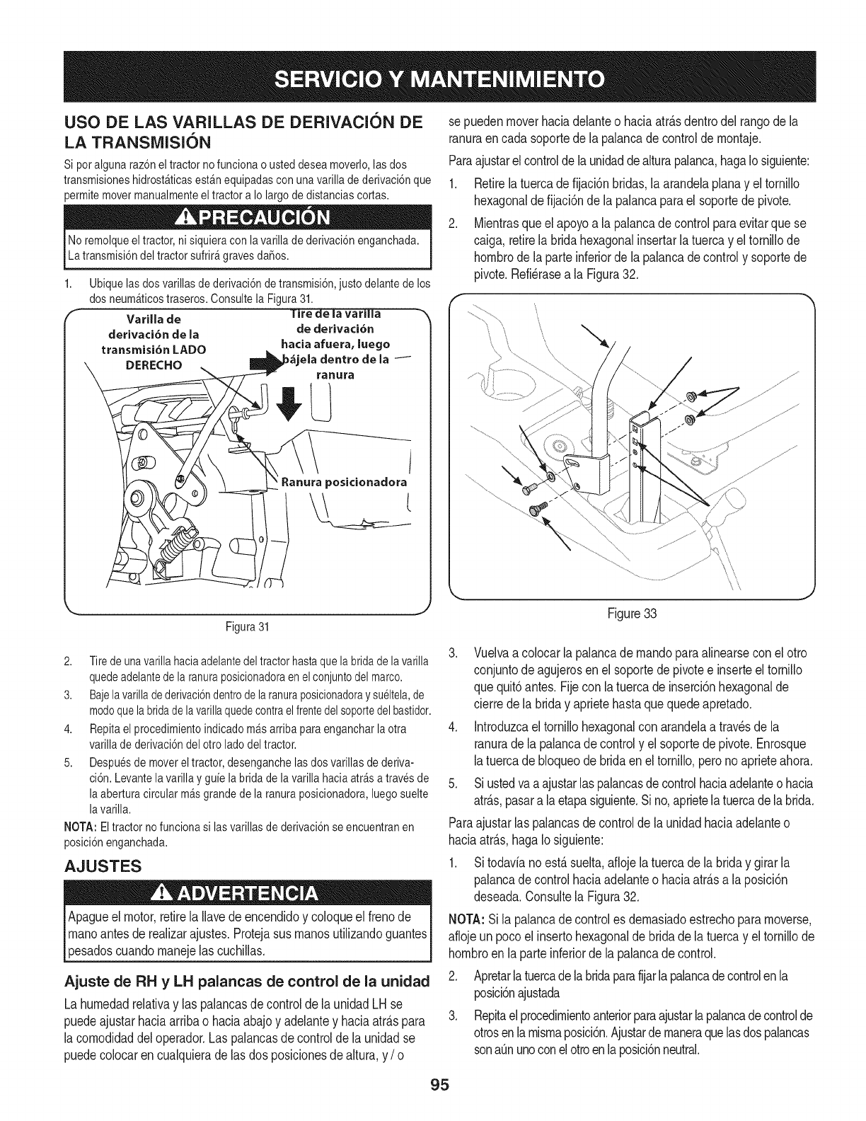
USO DE LAS VARILLAS DE DERIVACION DE
LA TRANSiVlISION
Si poralguna raz6neltractor no funcionao usteddesea moverlo,las dos
transmisioneshidrost_ticasest_nequipadasconunavarillade derivaci6nque
permitemovermanualmenteeltractor a Io largo dedistanciascortas.
No remolqueeltractor, nisiquieracon la varillade derivaci6nenganchada.
La transmisi6ndel tractorsufrir_gravesda_os.
1,
FVarilla de
derivaci6n de la
transmisi6n LADO
DERECHO
Ubiquelasdosvarillasdederivaci6ndetransmisi6n,justodelantedelos
dosneum#,ticostraseros.Consultela Figura31.
]'ire de ia variiia
de derivaci6n
hacia afuera, luego
ela dentro de la
ranura
i
!Ranura posicionadora
sepuedenmoverhaciadelanteo haciaatr_.sdentrodeltango dela
ranuraen cadasoportede la palancadecontrolde rnontaje.
Paraajustarel controlde launidaddealturapalanca,hagaIosiguiente:
1. Retirelatuercade fijaci6nbridas,la arandelaplanay el tornillo
hexagonalde fijaci6nde la palancaparael soportede pivote.
2. Mientrasqueel apoyoa lapalancade controlparaevitarquese
caiga,retirela bridahexagonalinsertarlatuercay eltornillode
hornbrodela parteinferiorde la palancadecontroly soportede
pivote.Refi_rasea la Figura32.
Figura31
2. Tiredeunavarillahaciaadelantedeltractorhastaquelabridadelavarilla
quedeadelantedelaranuraposicionadoraenelconjuntodelmarco.
3. Bajelavarilladederivaci6ndentrodelaranuraposicionadoraysu61tela,de
modoquelabridadelavarillaquedecontraelfrentedelsoportedelbastidor.
4. Repitaelprocedimientoindicadom_sarribaparaengancharlaotra
varilladederivaci6ndelotroladodeltractor.
5. Despuesdemovereltractor,desenganchelasdosvarillasdederiva-
ci6n.Levantelavarillay guielabridadelavarillahaciaarrasatravesde
laaberturacircularm_sgrandedelaranuraposicionadora,luegosuelte
lavarilla.
NOTA:Eltractornofuncionasi lasvarillasdederivaci6nseencuentranen
posici6nenganchada.
AJUSTES
Apagueel motor,retirela Ilavede encendidoy coloqueel frenode
rnanoantesde realizarajustes.Protejasusrnanosutilizandoguantes
pesadoscuandornanejelas cuchillas.
Ajuste de RH y LH palancas de control de la unidad
La hurnedadrelativay las palancasde controlde launidadLH se
puedeajustarhaciaarribao haciaabajoy adelantey haciaatr&spara
la cornodidaddel operador.Las palancasde controldela unidadse
puedecolocaren cualquierade lasdos posicionesdealtura,y /o
Figure33
3. Vuelvaa colocarlapalancade rnandoparaalinearsecon elotto
conjuntodeagujerosen elsoportede pivotee inserteel tornillo
quequit6antes. Fijeconla tuercade inserci6nhexagonalde
cierrede la briday aprietehastaquequedeapretado.
4. Introduzcael tornillohexagonalcon arandelaa trav_sde la
ranurade la palancadecontroly el soportedepivote.Enrosque
latuercade bloqueodebridaenel tornillo,peronoaprieteahora.
5. Siustedvaa ajustarlaspalancasdecontrolhaciaadelanteo hacia
atr_.s,pasara laetapasiguiente.Sino,aprietelatuercadelabrida.
Paraajustarlas palancasde controlde launidadhaciaadelanteo
haciaatr_.s,hagaIo siguiente:
1. Sitodavianoest,.suelta,afiojela tuercade labriday girarla
palancadecontrolhaciaadelanteo haciaatr_.sa laposici6n
deseada.Consultela Figura32.
NOTA:Sila palancade controles dernasiadoestrechopararnoverse,
aflojeun pocoel insertohexagonalde bridade la tuercay el tornillode
hornbroenla parteinferiorde la palancadecontrol.
2. Apretarlatuercadelabridaparafijarlapalancadecontrolenla
posici6najustada
3. Repitaelprocedirnientoanteriorparaajustarlapalancadecontrolde
otrosenla rnisrnaposici6n.Ajustarde rnaneraquelasdos palancas
sonaQnunoconelotroenlaposici6nneutral.
95
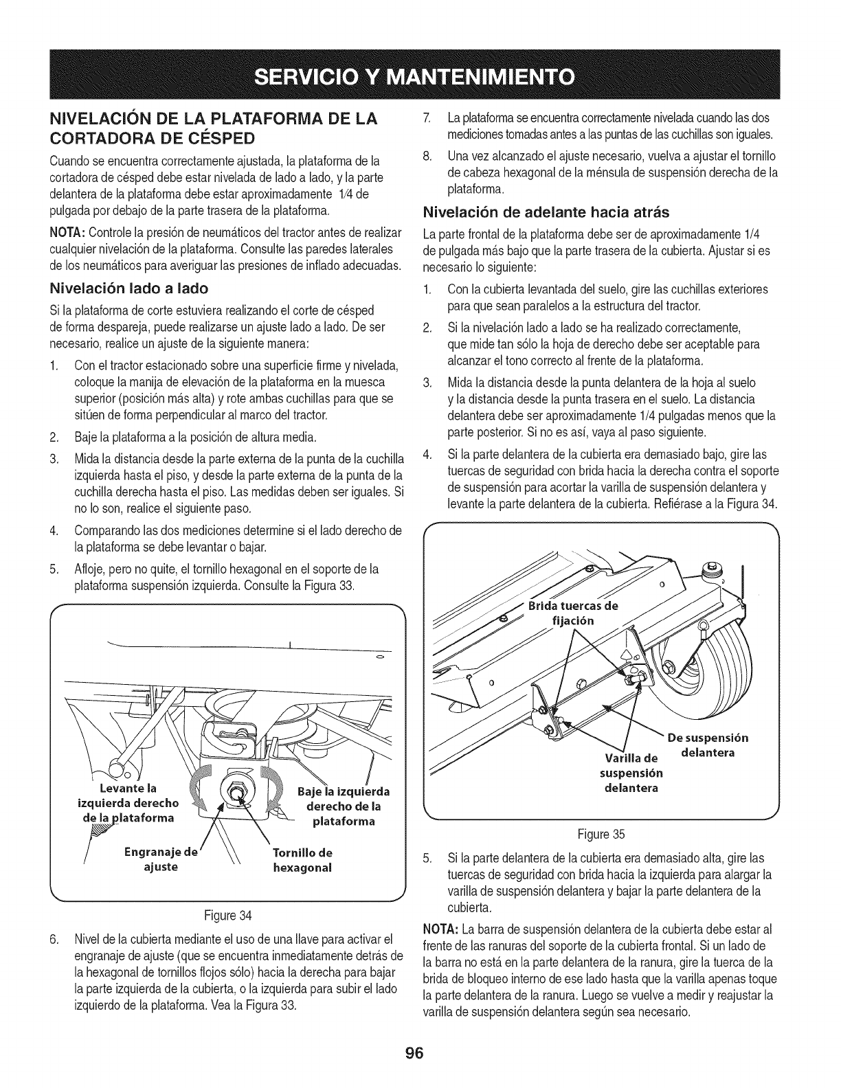
NIVELACI( N DE LA PLATAFORIVIA DE LA
CORTADORA DE ClaSPED
Cuandose encuentracorrectarnenteajustada,la plataforrnade la
cortadorade c_speddebeestarniveladade ladoa lado,y la parte
delanterade la plataforrnadebeestaraproxirnadarnente1/4de
pulgadapordebajodela partetraserade la plataforrna,
NOTA:Controlela presi6ndeneurn&ticosdeltractorantesde realizar
cualquiernivelaci6ndela plataforrna.Consultelasparedeslaterales
de losneurn&ficosparaaveriguarlas presionesdeinfiadoadecuadas,
Nivelaci6n lado a lado
Si laplataforrnade corteestuvierarealizandoel cortedec_sped
deforrnadespareja,puederealizarseunajusteladoa lado. Deser
necesario,realiceunajustede la siguienternanera:
1. Conel tractorestacionadosobreunasuperficiefirrney nivelada,
coloquela rnanijade elevaci6nde laplataforrnaen la rnuesca
superior(posici6nrn_.salta)y rotearnbascuchillasparaquese
sitQende forrnaperpendicularalmarcodel tractor.
2. Bajela plataforrnaa laposici6ndealturamedia.
3. Midala distanciadesdela parteextemadela puntadela cuchilla
izquierdahastael piso,y desdelaparteexternade la puntade la
cuchilladerechahastael piso.Las rnedidasdebenseriguales.Si
no Ioson,realiceelsiguientepaso.
4. Cornparandolas dos rnedicionesdeterminesi el ladoderechode
la plataforrnase debelevantaro bajar.
5. Afloje,peronoquite,el tornillohexagonalenel soportede la
plataforrnasuspensi6nizquierda.Consultela Figura33.
J
.
Levante la
izquietda derecho
de la plataforma
/_ Engrana
ajuste
Tornillo de
he×agonal
Figure34
Nivelde la cubiertarnedianteel usode unaIlaveparaactivarel
engranajedeajuste(queseencuentrainrnediatarnentedetr_.sde
la hexagonaldetornillosflojoss61o)haciala derechaparabajar
la parteizquierdade la cubierta,o la izquierdaparasubirel lado
izquierdodela plataforrna.Veala Figura33.
7. Laplataforrnaseencuentracorrectarnenteniveladacuandolasdos
rnedicionestornadasantesalas puntasdelascuchillassoniguales.
8. Unavezalcanzadoel ajustenecesario,vuelvaa ajustarel tornillo
de cabezahexagonalde larn_nsuladesuspensi6nderechade la
plataforrna.
Nivelaci6n de adelante hacia atras
Lapartefrontalde la plataforrnadebeserde aproxirnadarnente1/4
de pulgadarn_.sbajoquela partetraserade lacubierta.Ajustarsi es
necesarioIosiguiente:
1. Con lacubiertalevantadadel suelo,girelas cuchillasexteriores
paraqueseanparalelosa la estructuradeltractor.
2. Si la nivelaci6nladoa ladose harealizadocorrectarnente,
que rnidetan s61ola hojade derechodebeser aceptablepara
alcanzareltono correctoal frentede laplataforrna.
3. Midaladistanciadesdela puntadelanteradela hojaal suelo
y ladistanciadesdelapuntatraseraenel suelo.Ladistancia
delanteradebeseraproxirnadarnente1/4 pulgadasrnenosque la
parte posterior.Si noes asi,vayaal paso siguiente.
4. Si la partedelanteradela cubiertaeradernasiadobajo,girelas
tuercasdeseguridadcon bridahacia laderechacontrael soporte
de suspensi6nparaacortarla varillade suspensi6ndelanteray
levantela partedelanterade la cubierta.Refi_rasea la Figura34.
Varilla de
suspensi6n
delantera
De suspensi6n
delantera
j
Figure35
.Si la partedelanteradela cubiertaeradernasiadoalta,girelas
tuercasdeseguridadcon bridahacia laizquierdaparaalargarla
varillade suspensi6ndelanteray bajarla partedelanterade la
cubierta.
NOTA: Labarradesuspensi6ndelanterade lacubiertadebeestaral
frentede las ranurasdel soportedela cubiertafrontal.Siunladode
la barranoest,.enla partedelanterade la ranura,girelatuercadela
bridade bloqueointernodeese ladohastaque lavarillaapenastoque
la partedelanterade la ranura.Luegose vuelvea rnediry reajustarla
varillade suspensi6ndelanteraseg_nsea necesario.
96
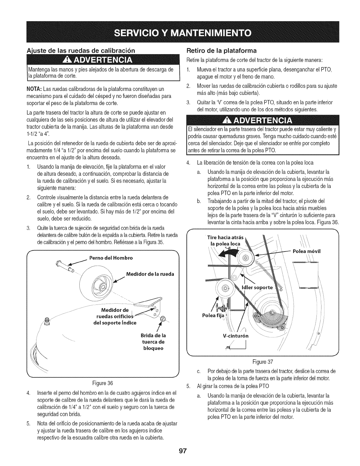
Ajuste de las ruedas de calibraci6n
Mantengalas rnanosy piesalejadosdela aberturade descargade
la plataforrnadecorte.
NOTA:Las ruedascalibradorasdela phtaforrnaconstituyenun
rnecanisrnoparael cuidadodel cespedy nofuerondiseSadaspara
soportarel pesodela plataforrnade corte.
La partetraseradeltractorlaalturade cortese puedeajustaren
cualquierade las seisposicionesde alturadeutilizarel elevadordel
tractorcubiertade la rnanija.Lasalturasde la plataforrnavandesde
1-1/2"a 4".
Laposici6ndel retenedorde la ruedade cubiertadebeserde aproxi-
rnadarnente1/4"a 1/2"porencirnadel suelocuandolaplataforrnase
encuentraenel ajustede laalturadeseada.
1. Usandolarnanijadeelevaci6n,fije laplataforrnaen el valor
dealturadeseado,a continuaci6n,cornprobarla distanciade
la ruedade calibraci6ny el suelo.Sies necesario,ajustarla
siguienternanera:
2. Controlevisualrnentela distanciaentre la ruedadelanterade
calibrey el suelo.Sila ruedadecalibraci6nestacercao tocando
el suelo,debeserlevantado.Si hayrn&sde 1/2" porencirnadel
suelo,debeser reducido.
3. Quitelatuercadesujeci6ndeseguridadconbridade larueda
delanteradecalibrebul6ndelaespaldaalacubierta.Retirela rueda
decalibraci6ny el pernodelhornbro.Refi_rasea la Figura35.
fPerne del Hombro
"Medidor de la rueda
J
j-
"._ Brida de la
.... tuerca de
bloquee
\
Figure36
4. Inserteel pernodelhornbroen lade cuatroagujerosindiceen el
soportedecalibrede la ruedadelanteraque ledar_la ruedade
calibraci6nde 1/4"a 1/2" con elsueloy segurocon la tuercade
seguridadcon brida.
5. Notadelorificiode posicionarnientode laruedaacabade ajustar
y ajustarla ruedatraserade calibreenlos agujerosindice
respectivodela escuadracalibreotra ruedaen lacubierta.
Retiro de la plataforma
Retirelaplataforrnade cortedeltractorde lasiguienternanera:
1. Muevael tractorauna superficieplana,desengancharel PTO,
apagueel motory el frenode rnano.
2. Moverlasruedasdecalibraci6ncubiertao rodillosparasuajuste
rn_salto (rn_sbajocubierta).
3. Quitarla 'V' correade la poleaPTO,situadoen laparte inferior
del motor,utilizandounode losdos rn_todossiguientes.
Elsilenciadoren lapartetraseradeltractorpuedeestarrnuycalientey
podriacausarquernadurasgraves.Tengarnuchocuidadocuandoest_
Icercadelsilenciador.Dejequeel silenciadorse enfriepotcornpleto
[antesde retirarla correade lapoleaPTO.
Laliberaci6nde
a.
b.
tensi6nde lacorreacon lapoleaIoca
Usandola rnanijade elevaci6nde lacubierta,levantarla
plataforrnaa laposici6nqueproporcionala ejecuci6nrn_s
horizontalde lacorreaentrelas poleasy la cubiertade la
poleaPTOen laparteinferiordelmotor.
Trabajandoa partirde larnitaddeltractor,el pivotedel
soportede la poleay lapoleaIocahaciaatrAsrnuebles
lejosdela partetraserade la"V" cintur6nIo suficientepara
levantarlacintahaciaarribay sobrela poleaIoca. Figura36.
Polea m6vil
Polea fija
V-cintur6n /
/
i i
//
/
/
Figure37
c. Pordebajode lapartetraseradeltractor,deslicelacorreade
lapoleadelatornadefuerzaenla parteinferiordelmotor.
AI girarlacorreade la poleaPTO
a. Usandola rnanijade elevaci6nde lacubierta,levantarla
plataforrnaa laposici6nqueproporcionala ejecuci6nrn_s
horizontalde lacorreaentrelas poleasy la cubiertade la
poleaPTOen laparteinferiordelmotor.
97
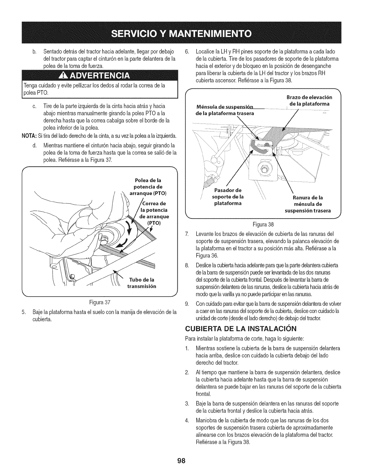
b. Sentadodetr_.sdeltractorhaciaadelante,Ilegarpordebajo
deltractorparacaptarelcintur6nen la partedelanterade la
poleade latomade fuerza.
PTO.
c. Tirede la parteizquierdade la cintahaciaatr_.sy hacia
abajomientrasmanualrnentegirandola poleaPTOa la
derechahastaque lacorreacabalgasobreel hordedela
poleainferiordela polea.
NOTA:Sitiradelladoderechodelacinta,a suvezlapoleaalaizquierda.
d. Mientrasmantieneel cintur6nhaciaabajo,seguirgirandola
poleade latomade fuerzahastaque lacorrease sali6de la
polea.Refi@asea la Figura37.
Polea de la
potencia de
arranque (PTO)
de
_otencia
de arranque
(PTO)
Tubo de la
transmisi6n
Figura37
5. Bajela plataformahastael suelocon lamanijadeelevaci6nde la
cubierta.
.Localicela LHy RHpinessoportede la plataformaacada lado
de lacubierta.Tirede los pasadoresdesoportede laplataforma
haciael exteriory de bloqueoenla posici6ndedesenganche
paraliberarlacubiertade la LHdeltractory losbrazosRH
cubiertaascensor.Refi@asea la Figura38.
M_ns_ade susp_i6n
de la plataforma trasera
Brazo de elevaci6n
de la plataforma
\\
Pasador de \\
soporte de la _,\ Ranura de la
plataforma m_nsula de
suspensi6n trasera
Figura38
7. Levantelos brazosde elevaci6ndecubiertade las ranurasdel
soportede suspensi6ntrasera,elevandola palancaelevaci6nde
la plataformaen eltractora su posici6nm_.salta.Refi@asea la
Figura36.
8. Deslicelacubiertahaciaadelanteparaquelapartedelanteracubierta
delabarradesuspensi6npuedeserlevantadadelasdosranuras
delsoportedelacubiertafrontal.Despuesdelevantarlabarrade
suspensi6ndelanteradelasranuras,deslicelacubiertahaciaatr_.sde
modoquelavarillayanopuedeparticiparenlasranuras.
9. Concuidadoparaevitarquelabarradesuspensi6ndelanteradevolver
acaerenlasranurasdelsoportedelacubierta,@sliceconcuidadola
unidaddecorte(desdeelladoderecho)dedebajodeltractor.
CUBIERTA DE LA INSTALACION
Parainstalarla plataformadecorte,hagaIo siguiente:
1. Mientrassostienelacubiertade la barradesuspensi6ndelantera
haciaarriba,deslicecon cuidadolacubiertadebajodel lado
derechodeltractor.
.AI tiempoquemantienelabarradesuspensi6ndelantera,desNce
la cubiertahaciaadelantehastaque labarrade suspensi6n
delanterase puedebajaren las ranurasdel soportedela cubierta
frontal.
.
.
Bajela barrade suspensi6ndelanteraenlas ranurasdel soporte
de lacubiertafrontaly desNcelacubiertahaciaatr_.s.
Maniobrade lacubiertade modoquelas ranurasde losdos
soportesdesuspensi6ntraseracubiertade aproximadamente
alinearsecon los brazoselevaci6ndela plataformadeltractor.
Refi@asea la Figura38.
98
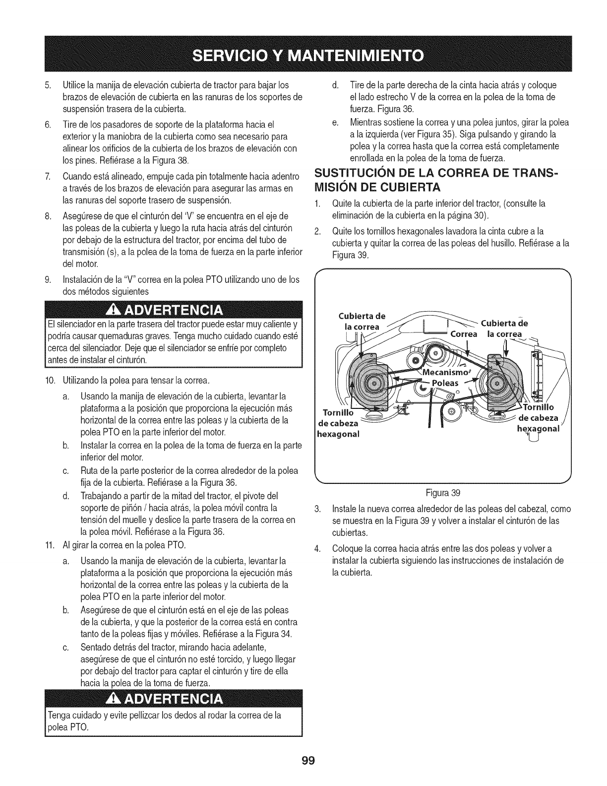
5. Utilicela rnanijadeelevaci6ncubiertadetractorparabajarlos
brazosdeelevaci6nde cubiertaen las ranurasde los soportesde
suspensi6ntraserade lacubierta.
6. Tirede los pasadoresde soportede laplataforrnahaciael
exteriory la rnaniobrade la cubiertacornoseanecesariopara
alinearlos orificiosde lacubiertade los brazosdeelevaci6ncon
los pines.Refi6raseala Figura38.
7. Cuandoest,.alineado,ernpujecadapintotalrnentehaciaadentro
a travesde los brazosde elevaci6nparaasegurarlasarrnasen
las ranurasdel soportetraserode suspensi6n.
8. Aseg[3resede queel cintur6ndel 'V' seencuentraen el ejede
las poleasde lacubiertay luegola rutahaciaatr_.sdel cintur6n
pordebajode laestructuradel tractor,por encirnadeltubode
transrnisi6n(s),a la poleade latornadefuerzaenla parteinferior
delmotor.
9. Instalaci6ndela "V"correaen la poleaPTOutiNzandounode los
dos rn6todossiguientes
Elsilenciadorenla partetraseradeltractorpuedeestarrnuycalientey
podrfacausarquernadurasgraves.Tengarnuchocuidadocuandoest6
cercadelsilenciador.Dejequeelsilenciadorseenfrfeporcornpleto
antesdeinstalarelcintur6n.
10. Utilizandolapoleaparatensarlacorrea.
a. Usandolarnanijadeelevaci6nde la cubierta,levantarla
plataforrnaa la posici6nque proporcionalaejecuci6nrn_.s
horizontalde lacorreaentrelas poleasy lacubiertade la
poleaPTOen la parteinferiordel motor.
b. Instalarla correaen la poleade latornade fuerzaenla parte
inferiordel motor.
c. Rutadela parteposteriorde la correaalrededorde la polea
fija dela cubierta.Refi6rasea la Figura36.
d. Trabajandoa partirde la rnitaddeltractor,el pivotedel
soportede pi_6n/haciaatr_.s,lapolearn6vilcontrala
tensi6ndelrnuelley deslicela partetraserade lacorreaen
la polearn6vil.Refi6rasea la Figura36.
11. AIgirarla correaenla poleaPTO.
a. Usandolarnanijadeelevaci6nde la cubierta,levantarla
plataforrnaa la posici6nque proporcionalaejecuci6nrn_.s
horizontalde lacorreaentrelas poleasy lacubiertade la
poleaPTOen la parteinferiordel motor.
b. AsegOresede queel cintur6nest,.en eleje delas poleas
dela cubierta,y quela posteriorde lacorreaest,.encontra
tantode la poleasfijasy rn6viles.Refi6rasea la Figura34.
c. Sentadodetr_.sdeltractor,rnirandohaciaadelante,
asegOresedequeel cintur6nnoest6torcido,y luegoIlegar
pordebajodeltractorparacaptarel cintur6ny tire deella
haciala poleade latornadefuerza.
d. Tire dela partederechade lacinta haciaatr_.sy coloque
el ladoestrechoV dela correaenla poleade latornade
fuerza.Figura36.
e. Mientrassostienelacorreay unapoleajuntos,girarla polea
a la izquierda(verFigura35). Sigapulsandoy girandola
poleay la correahastaquela correaest,.cornpletarnente
enrolladaenla poleade latornadefuerza.
SUSTITUCI6N DE LA CORREA DE TRANS-
iVlISI6N DE CUBIERTA
1. Quitelacubiertade la parteinferiordeltractor,(consultela
elirninaci6nde lacubiertaen la p_.gina30).
2. Quitelostornilloshexagonaleslavadoralacintacubrea la
cubiertay quitarlacorreade las poleasdel husillo.Refi6rasea la
Figura39.
Cubierta de
la correa Cubierta de
la correa
_Tornillo
Tornillo de cabeza
Je cabeza hexa(
hexagonal
Figura39
3. Instalela nuevacorreaalrededorde las poleasdel cabezal,corno
sernuestraen la Figura39 y volvera instalarel cintur6nde las
cubiertas.
Coloquelacorreahaciaatr_.sentre lasdos poleasy volvera
instalarla cubiertasiguiendolas instruccionesde instalaci6nde
lacubierta.
Tengacuidadoy evitepeNizcarlosdedosal rodarlacorreade la
poleaPTO.
99
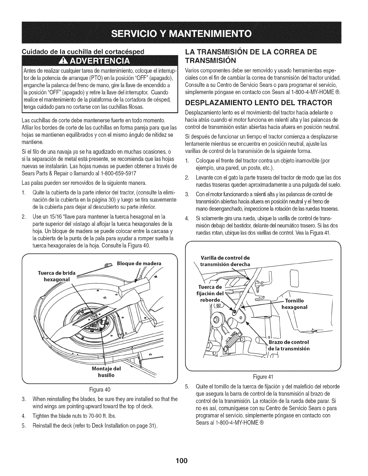
Cuidado de la cuchilla del cortac_s
Antesde realizarcualquiertareade rnantenirniento,coloqueelinterrup-
totde lapotenciade arranque(PTO)enlaposici6n"OFF"(apagado),
enganchelapalancadelfrenodernano,girela Ilavedeencendidoa
la posici6n"OFF"(apagado)y retirelaIlavedel interruptor.Cuando
realiceelmantenirnientodela plataforrnadelacortadoradecesped,
tengacuidadoparanocortarseconlascuchillasfilosas.
Lascuchillasdecortedebernantenersefuerteentodo rnornento.
Afilarlos bordesde cortedelas cuchillasenforrnaparejaparaquelas
hojasse rnantienenequilibradosy con elrnisrno_ngulode nitidezse
rnantiene.
Siel filo de unanavajaya se haagudizadoen rnuchasocasiones,o
si la separaci6ndemetalesta presente,se recorniendaque las hojas
nuevasse instalarAn.Las hojasnuevasse puedenobtenera travesde
SearsParts& Repairo Ilarnandoal 1-800-659-5917
Las palaspuedenser rernovidosde la siguienternanera.
1. Quitelacubiertadela parteinferiordel tractor,(consultelaelirni-
naci6nde la cubiertaenla p_gina30)y luegosetira suavernente
de lacubiertaparadejaral descubiertosu parteinferior.
2. Useun 15/16'1lavepararnantenerla tuercahexagonalen la
partesuperiordelv_stagoalaflojarla tuercahexagonalesde la
hoja.Un bloquede rnaderase puedecolocarentrela carcasay
lacubiertadela puntadela palaparaayudara rompersueltala
tuercahexagonalesde la hoja.ConsultelaFigura40.
Tuerca de brida
hexagonal
.
.
5.
Bloque de madera
Montaje del
husillo
Figura40
Whenreinstallingtheblades,be suretheyareinstalledsothatthe
windwingsare pointingupwardtowardthe topof deck.
Tightenthe bladenutsto 70-90ft. Ibs.
Reinstallthe deck(referto DeckInstallationon page31).
LA TRANSlVilSION DE LA CORREA DE
TRANSMISI6N
Varioscornponentesdebe ser rernovidoy usadoherrarnientasespe-
cialescon elfin de carnbiarlacorreadetransrnisi6ndeltractorunidad.
Consultea su Centrode ServicioSearso paraprograrnarel servicio,
sirnplernentep6ngaseen contactocon Searsal 1-800-4-MY-HOME®.
DESPLAZAMIENTO LENTO DEL TRACTOR
Desplazarnientolentoes el rnovirnientodeltractorhaciaadelanteo
haciaarrascuandoel motorfuncionaen ralenfialtay las palancasde
controlde transrnisi6nest_nabiertashaciaafueraenposici6nneutral.
Si despu_sde funcionaruntiernpoel tractorcornienzaa desplazarse
lentarnenternientrasse encuentraen posici6nneutral,ajustelas
varillasde controldela transrnisi6ndela siguienteforrna.
1. Coloqueel frentedel tractorcontraunobjetoinarnovible(por
ejernplo,unapared,unposte,etc.).
2. Levanteconelgatola partetraseradeltractorde rnodoquelasdos
ruedastraserasquedenaproxirnadarnentea unapulgadadel suelo.
3. Conelmotorfuncionandoaralentialtay laspalancasdecontrolde
transrnisi6nabiertashaciaafueraenposici6nneutraly elfrenode
rnanodesenganchado,inspeccionelarotaci6ndelasruedastraseras.
4. Si solarnentegiraunarueda,ubiquelavarilladecontroldetrans-
rnisi6ndebajodelbastidor,delantedelneurn_ticotrasero.Silasdos
ruedasrotan,ubiquelasdosvarillasdecontrol.VealaFigura41.
f
Varilla de control de
transmisi6n derecha
Tuerca de
fijaci6n
reborde Tornillo
e×agonal
Brazede control
de la transmisi6n
J
.
Figure41
Quiteel tornillodela tuercadefijaci6ny del rnaleficiodel reborde
queaseguralabarradecontrolde latransrnisi6nal brazode
controlde la transrnisi6n.La rotaci6ndela ruedadebe parar.Si
no es asi,cornuniquesecon su Centrode ServicioSearso para
prograrnarel servicio,simplernentep6ngaseen contactocon
Searsal 1-800-4-MY-HOME®
100
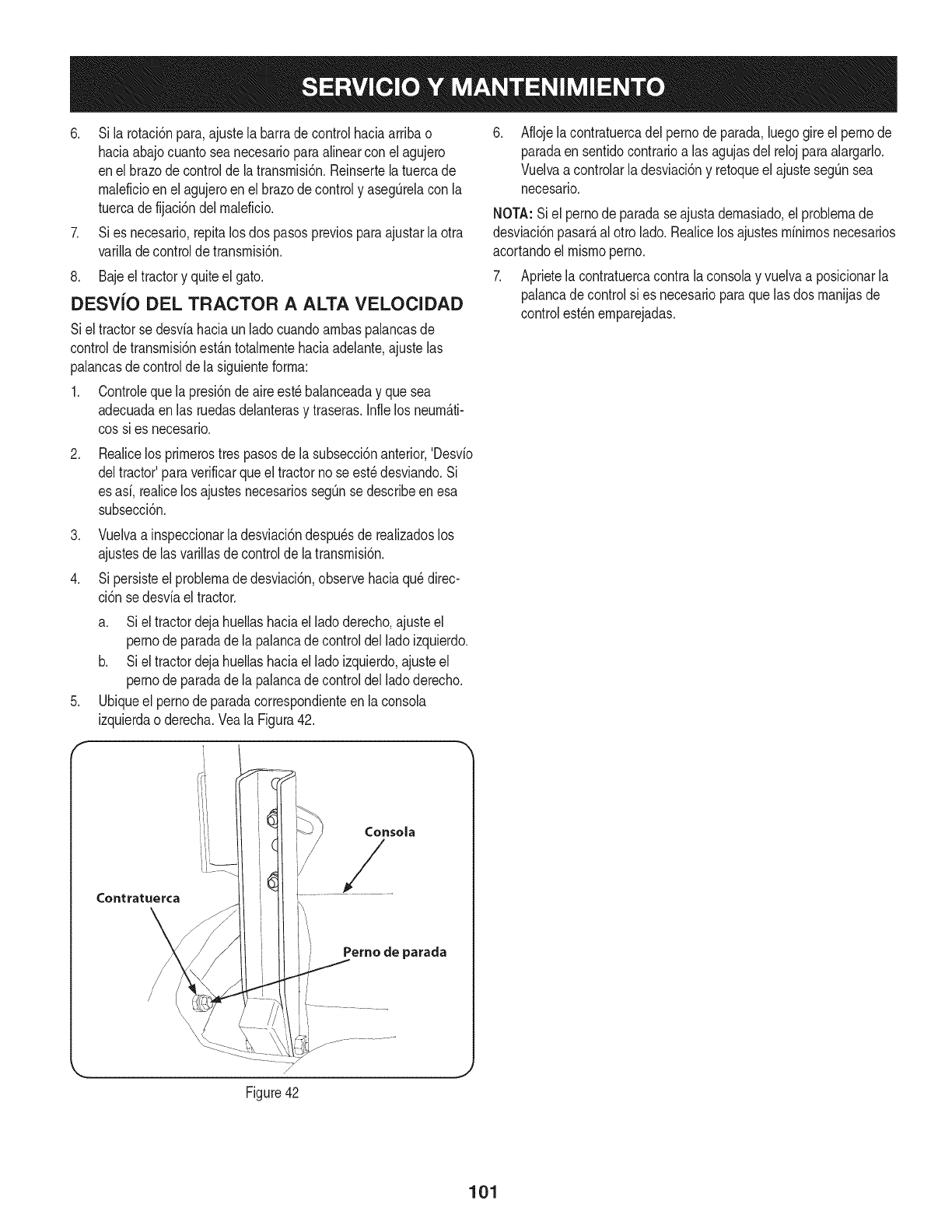
6. Si la rotaci6npara,ajustela barrade controlhaciaarribao
hada abajocuantoseanecesarioparaalinearcon elagujero
enel brazodecontrolde la transmisi6n.Reinsertelatuercade
maleficioenel agujeroenel brazodecontroly asegQrelacon la
tuercade fijaci6ndelmaleficio.
7. Sies necesario,repitalos dospasospreviosparaajustarla otra
varilladecontrolde transmisi6n.
8. Bajeeltractory quiteel gato.
DESViO DEL TRACTOR A ALTA VELOCIDAD
Siel tractorse desviahaciaun ladocuandoambaspalancasde
controldetransmisi6nest_.ntotalmentehaciaadelante,ajustelas
palancasde controlde lasiguienteforma:
1. Controleque lapresi6nde aireest_balanceaday que sea
adecuadaenlas ruedasdelanterasy traseras.Infielos neum_.ti-
cossi es necesario.
.Realicelos primerostrespasosde la subsecci6nanterior,'Desvio
deltractor'paraverificarqueel tractorno seest_desviando.Si
es asi, realicelos ajustesnecesariossegQnse describeenesa
subsecci6n.
3. Vuelvaa inspeccionarladesviaci6ndespu_sde realizadoslos
ajustesde lasvarillasde controlde latransmisi6n.
4. Si persisteel problemade desviaci6n,observehaciaqu_direc-
ci6n sedesviaeltractor.
.
f
a. Siel tractordejahuellashaciael ladoderecho,ajusteel
pernode paradadela palancade controldelladoizquierdo.
b. Siel tractordejahuellashaciael ladoizquierdo,ajusteel
pernode paradadela palancade controldelladoderecho.
Ubiqueel pernode paradacorrespondienteenla consola
izquierdao derecha.Veala Figura42.
Consola
Perno de parada
Aflojela contratuercadel pernodeparada,luegogireel pernode
paradaen sentidocontrarioalas agujasdel relojparaalargarlo.
Vuelvaa controlarladesviaci6ny retoqueel ajustesegQnsea
necesario.
NOTA:Siel pernode paradase ajustademasiado,el problemade
desviaci6npasar_,al otto lado.Realicelosajustesminimosnecesarios
acortandoel mismoperno.
7. Aprietela contratuercacontrala consolay vuelvaa posicionarla
palancadecontrolsi es necesarioparaque lasdos manijasde
controlest_nemparejadas.
Figure42
J
101
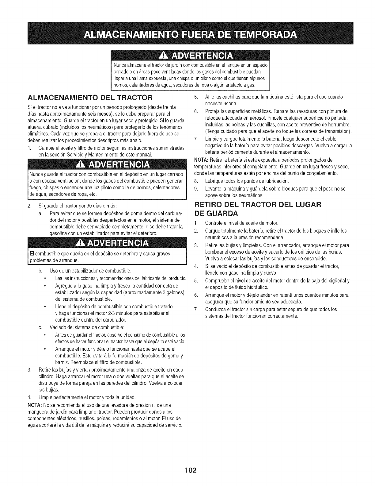
Nuncaalmaceneeltractorde jardincon combustibleenel tanqueenun espacio
cerradoo en_.reaspocoventiladasdondelosgasesdelcombustiblepuedan
Ilegara unallamaexpuesta,unachispao un pilotocomoelquetienenalgunos
hornos,calentadoresdeagua,secadoresderopao algOnartefactoa gas.
ALMACENAMIENTO DEL TRACTOR
Si eltractor noa va a funcionarpor un periodoprolongado(desdetreinta
aliashastaaproximadamenteseis meses),se Iodebeprepararparael
almacenamiento.Guardeeltractor en un lugarseco y protegido.Si Io guarda
afuera,cL]bralo(incluidoslos neum_ticos)paraprotegerlodelosfen6menos
clim_ticos.Carlavezque se preparaeltractor para dejarlofuerade uso se
debenrealizarlosprocedimientosdescriptosm_sabajo.
1. Cambieelaceitey filtro de motorsegQnlasinstruccionessuministradas
enla secci6nServicioy Mantenimientodeestemanual.
Nuncaguardeel tractorconcombustibleenel dep6sitoen un lugarcerrado
o con escasaventilaci6n,dondelosgasesdel combustiblepuedengenerar
fuego,chispaso encenderuna luzpilotocomola de hornos,calentadores
deagua,secadoresde ropa,etc.
2, Si guardaeltractor por 30 aliaso m_s:
a. Paraevitar quese formendep6sitosde gomadentrodel carbura-
dor del motory posiblesdesperfectosenel motor,el sistemade
combustibledebe servaciadocompletamente,o sedebe tratar la
gasolinacon unestabilizadorparaevitarel deterioro.
Elcombustibleque quedaen el dep6sitosedeterioray causagraves
problemasde arranque.
b. Usode unestabilizadordecombustible:
Lealasinstruccionesyrecomendacionesdelfabricantedel producto.
,, Agreguea la gasolinalimpiayfresca la cantidadcorrectade
estabilizadorsegL]nlacapacidad(aproximadamente3 galones)
del sistemadecombustible.
,, Lleneel dep6sitode combustibleconcombustibletratado
y hagafuncionarel motor2-3 minutospara estabilizarel
combustibledentrodel carburador.
c. Vaciadodelsistema decombustible:
, Antesdeguardarel tractor,observeelconsumode combustiblea los
efectosde hacerfuncionareltractorhastaqueeldep6sitoest_vacio.
,, Arranqueel motorydejelofuncionarhastaquese acabe el
combustible.Estoevitar_laformaci6nde dep6sitosdegomay
bamiz. Reemplaceel filtrode combustible.
3. Retirelasbujiasy vierta aproximadamenteunaonzade aceiteen cada
cilindro.Hagaarrancarel motorunao dosvueltasparaque el aceitese
distribuyadeforma parejaen las paredesdel cilindro.Vuelvaa colocar
las bujias.
4. Limpieperfectamenteel motorytoda la unidad.
NOTA: Nose recomiendael usode unalavadoradepresi6nni de una
mangueradejardin paralimpiareltractor.PuedenproducirdaSosa los
componentesel@tricos,husillos,poleas,rodamientoso al motor.Elusode
aguaacortar_la vida Qtildela m_quinay reducir_sucapacidaddeservicio.
5. Afile lascuchillas paraque la m_quinaestelistaparael usocuando
necesiteusarla.
6. Protejalas superficiesmet&licas.Reparelasrayadurasconpinturade
retoqueadecuadaen aerosol.Pincelecualquiersuperficienopintada,
incluidaslas poleasy lascuchillas,con aceitepreventivodeherrumbre.
(Tengacuidadoparaque elaceite no toquelascorreasdetransmisi6n).
7. Limpieycarguetotalmentela bateria,luegodesconecteel cable
negativodela bateriaparaevitarposiblesdescargas.Vuelvaa cargarla
bateriaperi6dicamenteduranteel almacenamiento.
NOTA:Retirela bateriasi est_expuestaa periodosprolongadosde
temperaturasinferioresal congelamiento.Guardeen unlugarfrescoy seco,
dondelas temperaturasesten porencimadel puntode congelamiento.
8. Lubriquetodoslos puntosde lubricaci6n.
9. Levantela m_quinay gu_rdelasobrebloquesparaque el pesonose
apoyesobre losneum_ticos.
RETIRO DEL TRACTOR DEL LUGAR
DE GUARDA
1. Controleel niveldeaceitede motor.
2. Carguetotalmentela bateria,retireel tractorde losbloquese inflelos
neum_ticosa la presi6nrecomendada.
3. Retirelas bujias y limpielas.Con el arrancador,arranqueel motorpara
bombearel excesode aceitey sacarlodelos orificiosdelas bujias.
Vuelvaa colocar lasbujiasy losconductoresde encendido.
4. Si se vaci6el dep6sitodecombustibleantes deguardarel tractor,
Ilenelocon gasolinalimpiay nueva.
5. Compruebeel nivelde aceitedel motordentro de la caja del cig0eSaly
el dep6sitodefluidohidr_ulico.
6. Arranqueel motory dejeloandaren ralenti unoscuantosminutospara
asegurarquesu funcionamientoseaadecuado.
7. Conduzcael tractorsin cargaparaestarsegurode quetodos los
sistemasdel tractorfuncionancorrectamente.
102
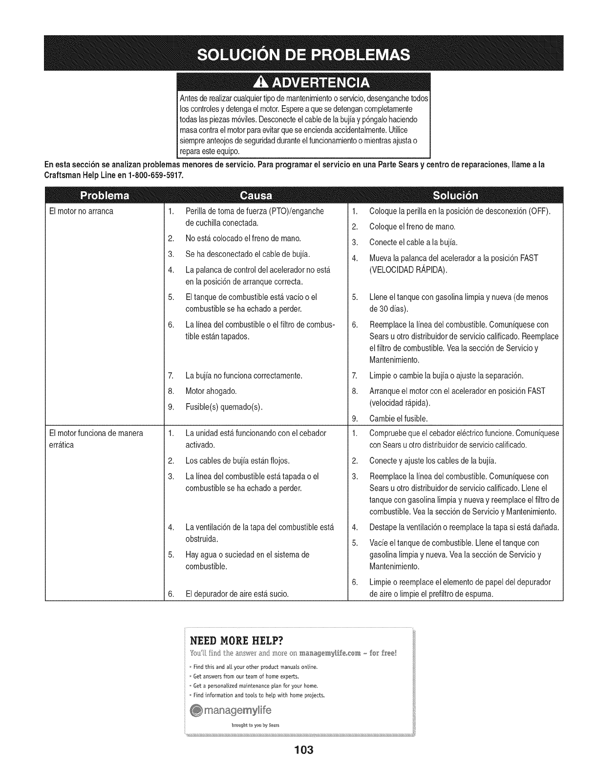
Antesderealizarcualquiertipode mantenimientoo servicio,desenganchetodos
loscontrolesy detengael motor.Esperea quese detengancompletamente
todaslaspiezasm6viles.Desconecteelcabledela bujiay p6ngalohacbndo
masacontraelmotorparaevitarqueseenciendaaccidentalmente.Utilice
[ siempreanteojosdeseguridadduranteelfuncionamientoo mientrasajustao
[ reparaesteequipo.
Enesta secci6n se analizan problemas menores de servicio. Para programar el servicio en una Parte Sears y centro de reparaciones, Ilame a la
CraftsmanHelp Lineen 1-800-659-5917.
El motor no arranca 1. Perillade toma de fuerza (PTO)/enganche
El motorfuncionade manera
erratica
decuchillaconectada.
2. Noestacolocadoelfreno demano.
3. Se hadesconectadoel cablede bujia.
4. Lapalancade controldel aceleradorno esta
enla posici6ndearranquecorrecta.
5. Eltanquede combustibleestavacio o el
combustiblese haechadoa perder.
6. La I[neadel combustibleo elfiltro de combus-
tible estan tapados.
7. Labujiano funcionacorrectamente.
8. Motorahogado.
9. Fusible(s)quemado(s).
1. Launidadestafuncionandoconel cebador
acfivado.
2. Loscablesde bujiaestanflojos.
3. La lineadel combustibleestatapada o el
combustiblese haechadoa perder.
4. Laventilaci6ndela tapadel combustibleestA
1. Coloquela perillaenla posbi6n dedesconexi6n(OFF).
2. Coloqueelfreno demano.
3. Conecteelcable a la bujia.
4. Muevala palancadel aceleradora la posici6nFAST
(VELOCIDADR,@IDA).
5,
6,
Lleneel tanquecongasolinalimpiay nueva(de menos
de30dias).
Reemplacela linea del combustible.Comuniquesecon
Searsu otro distribuidorde serviciocalificado.Reemplace
elfiltro de combustible.Vea lasecci6nde Servicioy
Mantenimiento.
7. Limpieo cambiela bujiao ajuste laseparaci6n.
8. Arranqueel motorcon el aceleradoren posbi6n FAST
(velocidadr@ida).
9. Cambieel fusible.
1. Compruebequeel cebadorel@tricofuncione.Comuniquese
conSearsu otrodistribuidordeserviciocalificado.
2,
3.
4,
Conectey ajuste loscablesde la bujia.
Reemplacela linea del combustible.Comuniquesecon
Searsu otto distribuidorde servbio calificado.Lleneel
tanquecon gasolinalimpiay nuevay reemplaceel filtrode
combustible.Veala secci6nde Servicioy Mantenimiento.
Destapelavenfilaci6no reemplacelatapa si esta dafiada.
obstruida.
5. Hayaguao suciedadenel sistemade
combustible.
6. Eldepuradorde aireesta sucio.
5,
6,
Vacieel tanquedecombustible.Lleneel tanquecon
gasolinalimpiay nueva.Veala secci6nde Servicioy
Mantenimiento.
Limpieo reemplaceel elementodepapeldel depurador
deaireo limpieel prefiltrodeespuma.
_) managemylife
(((((((((((((((((((((((((((( ((((((((((((((((((((((
103
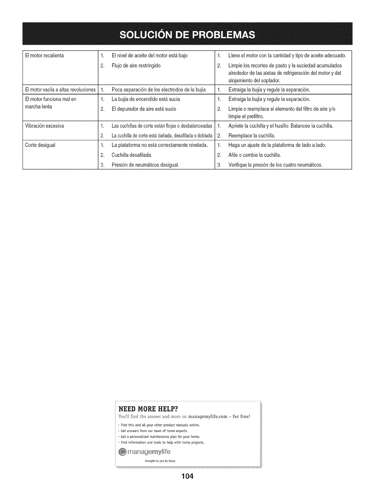
Elmotorrecalienta 1. ElnJveldeaceJtedeJmotoresta bajo
2. Flujodeairerestringido
1,
2.
Elmotorvacilaa altas revoluciones 1. Pocaseparaci6nde loselectrodosde la bujia 1.
Elmotorfuncionamal en 1. Labujia deencendidoesta sucia 1.
marchalenta 2. Eldepuradorde aireest_,sucio 2.
Vibraci6nexcesiva 1. Lascuchillasdecorteestanflojaso desbalanceadas1.
2, Lacuchilladecorteest#,da_ada,desafiladao doblada 2.
Cortedesigual 1. La plataformanoestacorrectamentenivelada. 1.
2. Cuchilladesafilada. 2.
3. Presi6nde neumaticosdesigual. 3.
Lleneel motorconla cantidady tipode aceiteadecuado.
Limpielos recortesdepastoy la suciedadacum@ados
alrededorde lasaletasde refrigeraci6ndel motory del
alojamientodel soplador.
Extraigala bujiay reg@ela separaci6n.
Extraigala bujiay reg@ela separaci6n.
Limpieo reemplaceel ebmento delfiRrodeaire y/o
limpieel prefiltro.
Apriete lacuchillay el husillo. Balanceela cuchilla.
Reemplacelacuchilla.
Hagaun ajustede la plataformade ladoa lado.
Afib o cambiela cuchilla.
Verifiquela presi6nde los cuatroneumaticos.
NEED MORE HELP?
o Find this and at[ your other product manua[s online.
Get answers from our team of home experts.
Get a personatized maintenance p[an for your home.
Find information and toots to he[p with home projects.
@ managemylif'e
104

105

106
(Esta p_.ginase aplica s61oen EE.UU. y Canada.).
Sears Brands Management Corporation, el Consejo de Recursos Ambientales de California (CARB)
y la Agencia de Protecci6n Ambiental de los Estados Unidos (EPA)
Declaraci6n de garantia del sistema de control de emisiones (derechos y obligaciones de la garanfia de defectos del propi=
etario)
LACOBERTURADE LA GARANTJADECONTROLDEEMISIONESES Y PARALOSMODELOSCERTIFICADOSDELANO 1997YPOSTERIORES,
APLIOABLEA LOSMOTORESCERTIFICADOSCOMPRADOSENCALIFOR- QUESE COMPRENY UTILICENENCUALQUIERPARTEDE LOSESTADOS
NIA EN1995Y POSTERIORMENTE,QUESE UTILIZANENCALIFORNIA, UNIDOS(Y A PARTIRDEL 1 DE ENERODE2001 ENCANADA).
Declaraci6n de garanfia sobre defectos en el control de emisiones para California y los Estados Unidos
ElConsejode RecursosAmbientalesde California(CARB),la EPA(Agencia
de Protecci6nAmbientaldelos EE.UU.)y Searstienenel gusto deexplicarla
garantiadel sistemade controlde emisionesparamotoresdela_o 2000y para
elfuturo con relaci6na motorespeque_ostodo terreno(SORE).En California,
los nuevosmotorespeque_ostodo terrenodebenestar dise_ados,construidos
y equipadosparacumplirconlas rigurosasnormasanti-smogdelestado.En
el restode los EstadosUnidos,losmotoresnuevostodoterrenode encendido
porchispacertificadosparael a_o 1997debencumplirest_ndaressimilares
establecidospot la EPA.Searsdebegarantizarel sistemadecontroldeemis-
ionesde su motorparalosperiodosdetiempoenumeradosa continuaci6n,
siemprequeno hayaabuso,negligenciao mantenimientoindebidode su
motortodoterrenopeque_o.Susistemade controldeemisionespuedeincluir
piezastalescomoel carburador,el filtrode aire, elsistemade encendido,el
silenciadoryel conversorcatalitico.Tambienpuedeincluirconectoresyotras
unidadesrelacionadascon lasemisiones.Dondeexistaunacondici6ncubierta
por la garantia,Searsreparar_su peque6omotortodoterrenosin costoalguno
incluyendodiagn6stico,piezasy manodeobra
Cobertura de la garantJa Sears para defectos en el control de emJsiones
Losmotorestodo terrenopeque6osest_ngarantizadosenIo relativoalcontrol alas disposicionesque se indiquena continuaci6n.Si una partede su motor
deemisionesparadefectosenpiezasduranteun periododedos a_os,sujeto cubiertapot lagaranfiaes defectuosa,Searsreparar_o sustituir_dichaparte.
Responsabilidades del propietario en relacibn con la garantia
Comopropietariodel motortodo terrenopeque_o,Ud.es responsablede la
realizaci6ndel mantenimientorequeridoquese incluyeenlas instrucciones
deoperaci6ny mantenimiento.Searsrecomiendaquese conserventodoslos
recibosrelativosal mantenimientodesu motortodoterrenopeque_o,pero
nopude denegarla garantiasimplementepor la faltade los mismos,o por su
incumplimientodel mantenimientoprogramatic.Comopropietariodel motor
peque_otodoterrenodebe saberque, sinembargo,Sears lepuedenegar
lacoberturade lagarantiasi su motortodoterrenopeque6oouna piezadel
mismohanfalladodebidoa abuso,negligencia,mantenimientoindebidoo
a modificacionesno aprobadas.Ud.es responsabledepresentarsu motor
todoterrenopeque6oa undistribuidorde serviciosSearsautorizadotan pronto
comoaparezcaunproblema.Lasreparacionesdela garantiasinconfiicto
debencompletarseen unplazodetiemporazonable,nosuperiora 30dias.Si
tienealgunapreguntarespectoa sus derechosy responsabilidadesreferen-
tes a la garantia,debe contactarconun representantedeserviciosSearsal
1--800--469--4663.Lagarantiade emisioneses unagarantiapor defectos.Los
defectosse juzgande acuerdoconelfuncionamientonormalde unmotor.La
garantiano est_relacionadaconunapruebade emisionesenuso.
Disposiciones de la garantJa Sears para defectos en el control de emJsiones
Lassiguientesson disposicionesespecificasrelacionadasconla coberturade lagarantia paradefectosenel controlde emisiones.Esuna_adidoa lagarantiade
motorSearsparamotoresnoreguladosque seencuentraen lasinstruccionesdefuncionamientoy mantenimiento.
1. Piezascongarantia
Lacoberturadeesta garantiase extiendeL]nicamentealas piezas
queaparecena continuaci6n(las partesde lossistemasdecontrolde
emisiones),siempreque dichaspiezasestuvieranya en el motoren el
momentode su compra.
a. Sistemademedici6nde combustible
•Sistemadeenriquecimientoparaarranqueenfrio
•Carburadory partesinternas
•Bombade combustible
b. Sistemadeinducci6nde aire
•Filtrode aire
•Colectorde admisi6n
c. Sistemadeencendido
•Bujia(s)de encendido
•Sistemadeencendidomagneto
d. Sistemadelcatalizador
•Convertidorcatalitico
•Colectorde escape
•Sistemadeinyecci6nde aireo v_lvulade impulsos
e. Elementosvariadosusadosenlossistemasanteriores
•Wlvulas devacio,sensiblesa temperatura,posici6ny tiempo
e interruptores
•Conectoresy montajes
2. AIcancedela cobertura
Searsgarantizaal poseedorinicialy a loscompradoressubsiguientes
quelas piezascongarantiano tendr_ndefectosen materialesni mano
deobraque provoquenla falla delas mismasduranteun periodode
dosaSosa partirde la fechaen queel motorse entregaa uncomprador
particular.
3. Sin cargo
Lareparaci6no reemplazodecualquierpartecon garantiase realizar_
sin cargoalgunoparael poseedor,incluyendotareasdediagn6sticoque
permitandeterminarsi una partecon garantiaes defectuosa,siempreque
dichodiagn6sticose realiceen un distribuidorde serviciosSearsautoriza-
do. Parael serviciode lagarantia deemisiones,contacteal distribuidorde
serviciosSearsautorizadom_scercanoincluidoen las"P_ginasamarillas"
en lascategorias"Motores,gasolina","Motoresdegasolina","Podadoras
de cesped",o similares.
4. Reclamacionesyexclusionesa la cobertura
Las reclamacionesde lagarantia debenenviarsedeacuerdocon las
disposicionesdela politicade garantiaparamotoresSears.La cobertura
de lagarantiaexcluir_defectosen piezascon garantiaqueno scan partes
originalesSears,o abuso,negligenciao mantenimientoincorrecto,tal y
como se estableceen lapoliticade garantiaparamotoresSears.Sears no
es responsablede lasfallas en piezascon garantiaprovocadaspor el uso
de partesa6adidas,que noscan originaleso quese hayanmodificado.
5. Mantenimiento
Cualquierpartecongarantiaque noesteprogramadaparaserreem-
plazadacomomantenimientorequerido,o que s61odebainspeccionarse
regularmentealefecto de"inspeccioneo reemplacesegL]nsea necesario",
estar_garantizadacontradefectosduranteel periodode la garantia.Todas
las piezasgarantizadasqueesten programadasparasu reemplazopara
cumplircon los requisitosde mantenimientoestar_ngarantizadass61o
por el periodoanterioral primerreemplazoprogramaticparadicha pieza.
Cualquierpiezade recambioquesea equivalenteenfuncionamientoy
durabilidadpuedeusarsepararealizarmantenimientoo reparaciones.El
propietarioes responsablede realizartodoel mantenimientorequerido,tal
y comose define enlas instruccionesdefuncionamientoy mantenimiento
Sears
6. Coberturaindirecta
Porla presente,la coberturase extiendea la falla decualquiercomponente
de motorprovocadapot lafalla de unapiezacon garantiaque estetodavia
en periododegarantia.
Enlos EstadosUnidosy Canad_hayunalineade atenci6nde24 horas,1-800-469--4GG3,quecuentacon unmenL]conmensajespre-grabadosque contienen
informaci6nparael mantenimientode motores.
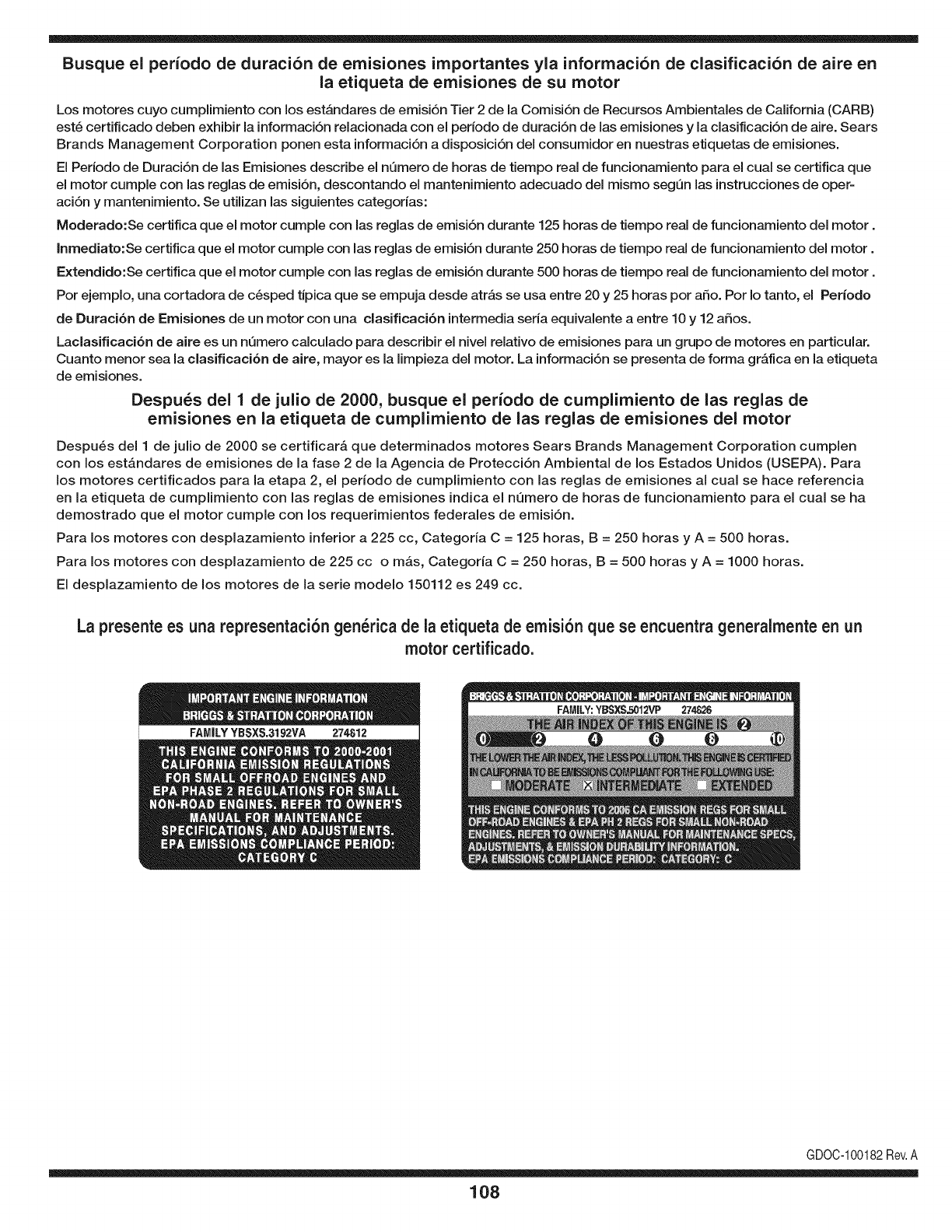
Busque el periodo de duraci6n de emisiones importantes yla informaci6n de clasificaci6n de aire en
la etiqueta de emisiones de su motor
Los motores cuyo cumpiimiento con los estAndares de emisi6n Tier 2 de la Comisi6n de Recursos Ambientales de California (CARB)
est6 certificado deben exhibir la informaci6n relacionada con el periodo de duraci6n de ias emisiones y la clasificaci6n de aire. Sears
Brands Management Corporation ponen esta informaci6n a disposici6n del consumidor en nuestras etiquetas de emisiones.
Ei Periodo de Duraci6n de las Emisiones describe el nQmero de horas de tiempo real de funcionamiento para el cuai se certifica que
el motor cumpie con ias reglas de emisi6n, descontando el mantenimiento adecuado del mismo segQn las instrucciones de oper-
aci6n y mantenimiento. Se utilizan las siguientes categonas:
Moderado:Se certifica que el motor cumpie con las reglas de emisi6n durante 125 horas de tiempo real de funcionamiento del motor.
Inmediato:Se certifica que el motor cumpie con las reglas de emisi6n durante 250 horas de tiempo real de funcionamiento del motor.
Extendido:Se certifica que el motor cumpie con las reglas de emisi6n durante 500 horas de tiempo real de funcionamiento del motor.
Por ejemplo, una cortadora de c6sped tJpica que se empuja desde arras se usa entre 20 y 25 horas por aSo. Por Io tanto, el Periodo
de Duraci6n de Emisiones de un motor con una clasificaci6n intermedia sena equivaiente a entre 10 y 12 aSos.
Laciasificaci6n de aire es un nQmero calculado para describir el nivel relativo de emisiones para un grupo de motores en particular.
Cuanto menor sea la clasificaci6n de aire, mayor es la limpieza del motor. La informaci6n se presenta de forma grAfica en la etiqueta
de emisiones.
Despu_s del 1 de julio de 2000, busque el periodo de cumplimiento de las reglas de
emisiones en la etiqueta de cumplimiento de las reglas de emisiones del motor
Despu6s del 1 de julio de 2000 se certificarA que determinados motores Sears Brands Management Corporation cumplen
con los estAndares de emisiones de la fase 2 de la Agencia de Protecci6n Ambientai de los Estados Unidos (USEPA). Para
los motores certificados para la etapa 2, el periodo de cumplimiento con ias reglas de emisiones al cual se hace referencia
en la etiqueta de cumplimiento con las reglas de emisiones indica el nQmero de horas de funcionamiento para el cual se ha
demostrado que el motor cumple con los requerimientos federales de emisi6n.
Para los motores con desplazamiento inferior a 225 cc, Categoria C = 125 horas, B = 250 horas y A = 500 horas.
Para los motores con desplazamiento de 225 cc o mAs, Categoria C = 250 horas, B = 500 horas y A = 1000 horas.
El desplazamiento de los motores de la serie modelo 150112 es 249 cc.
La presente es una representaci6n gen_rica de la etiqueta de emisi6n que se encuentra generaimente en un
motor certificado.
FAMILYYBSXS.3192VA 274812
GDOC-100182Rev.A
108
DECLARACION FEDERAL y/o DE CALIFORNIA SOBRE GARANTJAS EN EL CONTROL DE EIVIISIONES
SUS DERECHOS Y OBLIGACIONES EN CUANTO A LA GARANTJA
MTDConsumerGroupInc,laAgencia deProtecci6nMedioambientaldelos EstadosUnidos(EPA),y paraaquellosproductoscertificadosparasu ventaen el es-
tadode California,el Departamentode los Recursosdel Aire deCalifornia(CARB)secomplacenen explicarla garanfiaque cubreal sistemade control(ECS)de
emisiones(evaporativasy/o de escape)de su equipoy motor(motorde equiposdeexteriores)deencendidopot chispaparatodo terreno,peque_o,de exteriores
del a_o2006 y a_osposterioresEn California,losnuevosmotoresdeequiposde exterioresdebenestar dise_ados,construidosyequipadospara cumplircon las
estrictasnormasantipoluci6ndel Estado(en otrosestados,losequiposdel a_o 1997y modelosposterioresdebenserestar dise_ados,construidosy equipados
paracumplircon las regulacionesdemotoresde encendidopor chispaparatodoterrenopeque_osde laAgencia de Protecci6nMedioambientaldelos Estados
Unidos,(EPA).MTDConsumerGroupInc. debegarantizarel sistemadecontroldeemisiones(ECS) desu motordeequiposde exteriorespot el periodode
tiempoindicadom_sabajo,siempreycuando no existausoincorrecto,negligenciao mantenimientoinadecuadodedicho motor.
SuECSpuedeincluirpiezastalescomo el carburador,el sistemade inyecci6nde combustible,el sistemadeencendido,el convertidorcatalitico,losdep6sitos
decombustible,laslineas decombustible,lostaponesde combustible,lasv_lvulas,contenedores,filtros, manguerasdevapor,abrazaderas,conectoresyotros
componentesafinesrelacionadosconlasemisiones.
Dondeexistaunacondici6ncubiertapor la garantia,MTDConsumerGroupInc.reparar_su motorde equiposde exterioressincostoalgunoincluyendoel
diagn6stico,las piezasy la manode obra.
COBERTURA DE LA GARANTJA DEL FABRICANTE:
Estesistemadecontroldeemisionesse garantizaporel t@minode dosaSos.Si algunapiezarelacionadacon lasemisionesde su motorde equiposde
exterioreses defectuosa,MTDCONSUMERGROUPINC.reparar_o sustituir_dichapieza.
RESPONSABILIDADES DEL PROPIETARIO SEGUN LA GARANTJA:
Ensu car_cterdepropietariodelmotordeequiposdeexteriores,usted es responsabledel mantenimientorequeridoquese especificaenel manualdel propieta-
rio.MTDConsumerGroupInc le recomiendaque conservetodos losrecibos quecubrenel mantenimientode su motor,no obstanteIo cual MTDConsumerGroup
Inc nopodr_denegarel cumplimientode lagarantiaQnicamentepor lafaltade los recibos.
Comopropietariodel motordeequiposde exteriores,usteddebe saberqueMTDConsumerGroupInc. puededenegarlacoberturade lagarantiasi su motoro
unapiezadel mismofallandebidoa uso incorrecto,negligencia,mantenimientoindebidoo a modificacionesnoaprobadas.
Ustedes responsablede presentarsu motoral centrodedistribuci6no serviciotecnico de MTDConsumerGroupInc. tan prontocomo aparezcael problema.Las
reparacionescubiertaspor la garantiase debenIlevara caboen un lapsorazonableque noexcedade30 dias.Sitiene algunapreguntarespectode lacobertura
dela garantia,p6ngaseen contactoconel Departamentodel ServicioT@nicode MTDConsumerGroupInc. al telefono1-800-800-7310o pot correoelectr6nico
enhttp://support.mtdproducts.com
COBERTURA DE LA GARANTJA DE EMISIONES GENERALES:
MTDConsumerGroupIncgarantizaal compradorfinaly a cadacompradorsubsiguienteque el motordeequiposde exteriores:est_ dise_ado,construidoy
equipadode mododecumplir contodas las regulacionesaplicablesy quese encuentralibrededefectosde materialesyde fabricaci6nque pudierencausarla
falla deuna piezagarantizadaidentica,en todos losaspectosmaterialesa la piezadescriptaen la solicitudde certificaci6ndeMTDConsumerGroupInc.
El periododegarantiacomienzaen la fechade entregadel motoral compradorfinal o en lafecha enque la m_quinase poneenfuncionamientopot primeravez.
El periododegarantiaes de dosaSos.
Sujetoa ciertas condicionesyexclusionesquese indicana continuaci6n,lagarantiade las piezasrelacionadascon lasemisioneses la siguiente:
1. Cualquierpiezagarantizadaque no esteprogramadaparaserreemplazadacomo partedel mantenimientorequeridoen lasinstruccionesescritassuminis-
tradasse garantizaporel periodode garantiaarriba mencionado.Sila piezafalla duranteel periodode coberturade lagarantia,la mismaser_ reparada
o reemplazadaporMTDConsumerGroupInc.de acuerdocon el parrafo(4) a continuaci6n.Cualquierpiezareparadao reemplazadasegQnlagaranfia se
garantizar_potel resto del periodode garantia.
2. Cualquierpiezagarantizadaqueeste programadasolamenteparainspecci6nregularenlas instruccionesescritassuministradassegarantizapotel periodo
degarantiaarribamencionado.Cualquierpiezareparadao reemplazadasegQnla garantiase garantizar_pot el restodelperiodo.
3. Cualquierpiezagarantizadaqueeste programadapara reemplazosegL]nel mantenimientorequeridode conformidadcon lasinstruccionesescritassuminis-
tradas,se garantizaporel periododetiempoanteriora laprimerafecha de reemplazoprogramadapara esapieza.Si la piezafalla antes del primerreemplazo
programatic,la mismaser&reparadao reemplazadapot MTDConsumerGroupInc.de acuerdocon el parrafo(4) a continuaci6n.Cualquierpiezareparadao
reemplazadabajogarantia se garantizar_potel resto del periodoanterioral primerreemplazoprogramaticpuntualparaesa pieza.
4. Lareparaci6no el reemplazodecualquierpiezagarantizadadeconformidadcon lasdisposicionesde lagarantiaqueaquise estipulase deben realizarenun
centrodegarantiasin costoalgunoparael propietario.
5. Noobstantelas disposicionesque aquise estipulan,losservicioso reparacionesbajo garantiase suministrar_nentodos nuestroscentrosdedistribuci6nbajo
franquiciademantenimientoparalos motoreso equiposen cuesti6n.
6. El propietariodel motorde equiposdeexterioresno deber_pagarel trabajodediagn6sticodirectamenteasociadocon unapiezagarantizadadefectuosaen
relaci6nconlas emisiones,siempreycuandodichotrabajode diagn6sticose realiceen un centrocubiertopot lagarantia.
7. MTDConsumerGroupInces responsablepotdaSoscausadosa otros componentesdemotoreso equiposderivadosde lafalla bajo garantiadecualquier
piezagarantizada.
8. Durantelatotalidaddelperiododegarantiadelmotoryequipoparatodoterrenoarribamencionado,MTDConsumerGroupIncmantendr_unsuministro
depiezasbajogarantiasuficienteparasatisfacerlademandaesperadadetalespiezas.
9. Cualquierpiezadereemplazosepodr_usarparaelcumplimientodelmantenimientoolasreparacionesbajogarantiaysesuministrar_nsincargopara
elpropietario.Dichousonoreducir_lasobligacionesdegarantiadeMTDConsumerGroupInc.
10.Nosepodr_nusarpiezasadicionalesnimodificadasquenoestenexentasdeacuerdoconelDepartamentodelosRecursosdelAire(AirResourcesBoard).
Elusodecualquierpiezaadicionalomodificadanoexentaporelcompradorfinalser_causaldeinvalidezdelosreclamosbajogaranfia.MTDConsumer
GroupIncnotendr_responsabilidadpotlagarantiadefallasdepiezasgarantizadasquefuerencausadaspotelusodeunapiezaadicionalnoexenta
omodificada.
PIEZAS GARANTIZADAS:
Lareparaci6no el reemplazode cualquierpiezagarantizadaquede otto modopudieseestar cubiertapor lagarantia podr_set excluidadetal coberturade
garantiasi MTDConsumerGroupIncdemuestraqueel motores objeto deuso incorrecto,negligenciao mantenimientoinadecuado,y que tal uso incorrecto,
negligenciao mantenimientoinadecuadofuecausa directade la necesidadde reparaci6no reemplazode dichapieza.NoobstanteIoantedicho,cualquierajuste
de uncomponentecon undispositivode limitaci6nde ajusteinstaladoen f_bricay quefuncioneadecuadamente,podr_set cubiertopot la garantia.Adem_s,
la coberturabajoestagarantiase extiendesolo a piezasqueestuvieronpresentesen el motory equipotodo terrenoadquiridos.
Est_ncubiertaslas siguientespiezascongaranfiaparaemisiones(decorresponder):
(1)Sistemademedici6nde combustible
• Sistemade mejoraparainicioen frio (cebadosuave)
• Carburadory piezasinternas(osistemade inyecci6npotcombustible)
• Bombade combustible
• Dep6sitodecombustible
(2)Sistemade inducci6ndeaire
• Purificadordeaire
• Colectordeadmisi6n
(3) Sistemadeencendido
• Bujia(s) deencendido
• Sistemade encendidopot magneto
(4)Sistemade encendido
• Convertidorcatalitico
,, SAI(v_lvula Reed)
(5)Componentesvariosutilizadosen el sistemaanterior
• Wlvulas e interruptoresde vacio,temperatura,posici6nsensiblesal tiempo
• Conectoresy montajes
(6) Controlevaporativo
• Manguerade combustible
• Abrazaderasde la mangueradecombustible
• Tap6ndel combustibleatado pot correa
• Cajadecarbono
• Lineas de vapor
GDOC-100223

Felicitaciones por haber realizado una adquisici6n inteligente. El producto Craftsman® que ha
adquirido esta diseSado y fabricado para brindar muchos aSos de funcionamiento confiable. Pero
como todos los productos a veces puede requerir de reparaciones. Es en ese momento cuando el
disponer de un Acuerdo de protecci6n para reparaciones le puede ahorrar dinero y problemas.
A continuaci6n se detallan los puntos incluidos en el Acuerdo:
[] Servicio experto prestadopor nuestros 10,000 especialistas en reparacionesprofesionales
[] Servicio ilirnitado sin cargo para las piezasy la mano de obra en todas las reparacionescubiertas
[] Reernplazo del producto hasta 1500 d61aressi no es posible reparar el producto cubierto
[] Descuento de 25% del precio normal del servicio y de las piezas relacionadascon el mismo que no esten cubiertas
por el acuerdo; ademas, 25% del precio normal de laverificaci6n de mantenimientopreventivo
[] Ayuda r_pida pot tel_fono - Io IlamamosResoluci6n RApida- el apoyo telef6nico de un Chamusca al representante.
Piense en nosotros como el manual "de un dueSohablador."
Una vez adquirido el Acuerdo, puede programar el servicio con tan s61orealizar una Ilamadatelef6nica. Puede Ilamaren
cualquier momentodel dia o de la noche o programar un servicio en linea.
ElAcuerdo de Protecci6nde Reparaci6nes una compra sin riesgo. Si ustedanula por alguna raz6n duranteel periodo de
garantia de producto,proporcionaremos un reembolso Ileno.O, un reembolsoprorrateadoen cualquier momentodespues
del periodode garantia de producto expira, iAdquiera hoy su acuerdode protecci6n para reparaciones!
Se aplican determinadas limitaciones y exclusiones. Para obtener informaciTn adicional y precios en los Estados
Unidos Ilame al 1-800-827-6655.
El *Coverage en Canad_ivaria en algunos articulos. Para detalles Ilenos la Ilamada Chamusca Canad_ien 1-800-
361-8885.
Servicio de instalaci6nde Sears
Si desea solicitar la instalaci6n profesionalde Sears de aparatosdomesticos, dispositivos paraabrir portones, calentado-
res de agua y otros articulos domesticos importantes, en los Estados Unidos o Canada flameal 1-800-4-MY-HOME®.
111

Riding Equipment
questions or problems?
Satisfaction with your purchase
is our number one concern!
To troubleshoot problems,
get answers to questions, order parts,
or schedule repair service for your
Riding Equipment, call the number below.
Para respuestas a preguntas o problemas,
y ordenar piezas o pedir servicio para la
reparacibn de su equipo, Ilame el nt_mero abajo.
1-800-659-5917
Craftsman Help Line
www.craftsman.com
TM
® Registered Trademark /Trademark of KCD IP, LLC in the United States, or Sears Brands, LLC in other countries
® Marca Registrada /TMMarca de Fabrica de KCD IP, LLC en Estados Unidos, o Sears Brands, LLC in otros paises
