MTD 19A30003799 User Manual TWO BIN BAGGER Manuals And Guides 1104051L
User Manual: MTD 19A30003799 19A30003799 MTD TWO BIN BAGGER - Manuals and Guides View the owners manual for your MTD TWO BIN BAGGER #19A30003799. Home:Lawn & Garden Parts:MTD Parts:MTD TWO BIN BAGGER Manual
Open the PDF directly: View PDF ![]() .
.
Page Count: 32

perator's
I:RnFrSMRN°
TWO BiN BAGGER
Model No. 247.24019
\
•Espanol, p. 18
iMPORTANT:
Read and follow all Safety
Rules and instructions before
operating this equipment.
For answers to your questions about
this product, Call:
1-800=659=5917
CraftsmanTractorHelp Line
7am = 7 pm CT, Mort. =Sun.
Sears Brands Management Corporation, Hoffman Estates, IL 60179 U.S.A.
Visit our website: www.craftsman.com FormNo.769-05633E
(March24,2011)

Safe Operation Practices .............................................. 3-4
Slope Guide ....................................................................... 5
Contents of Carton & Hardware Packs .......................... 6-7
Assembly and Installation ............................................ 8-14
Operation ........................................................................ 15
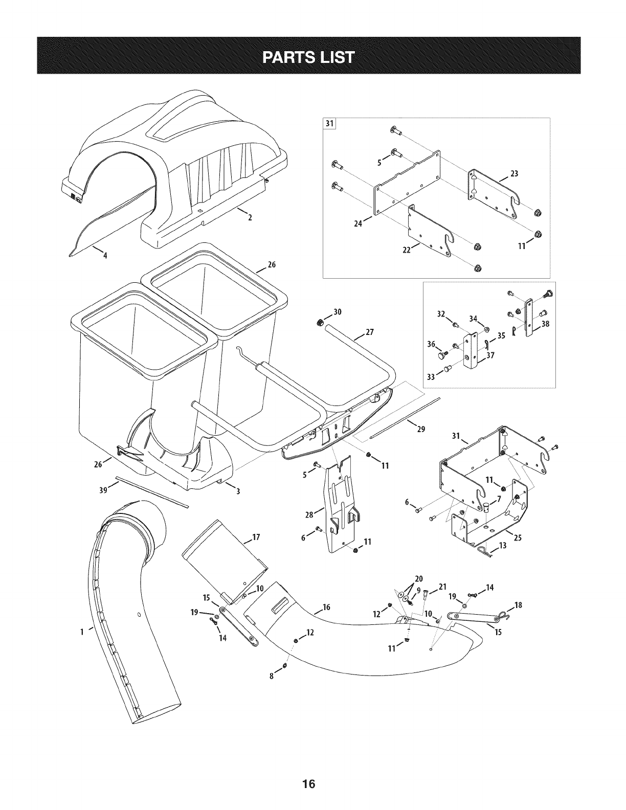
Parts List .................................................................... 16-17
Espa_ol ............................................................................ 18
Service Numbers ............................................. Back Cover
Craftsman Full Warranty
Ifthis Craftsmanproductfailsdueto a defectin materialor workmanshipwithinoneyearfromthe dateof purchase,returnit to any Searsstoreor
otherCraftsmanoutletinthe UnitedStatesfor free replacement.
ThiswarrantycoversONLYdefectsin materialandworkmanship.Searswill NOTpayfor:
• Replacementof bags,whichareexpendableitemsthatcan wearoutfromnormalusewithinthewarrantyperiod.
• Repairsnecessarybecauseof accidentorfailureto operateor maintainthe productaccordingto all suppliedinstructions.
Thiswarrantyappliesforonly 90daysif this productis everusedfor commercialor rentalpurposes.
Thiswarrantyappliesonly whilethisproductis usedinthe UnitedStates.
Thiswarrantygivesyou specificlegalrights,andyou mayalso haveotherrightswhichvary fromstateto state.
Sears, Roebuck and Co., Hoffman Estates, IL 60179
© SearsBrands,LLC 2
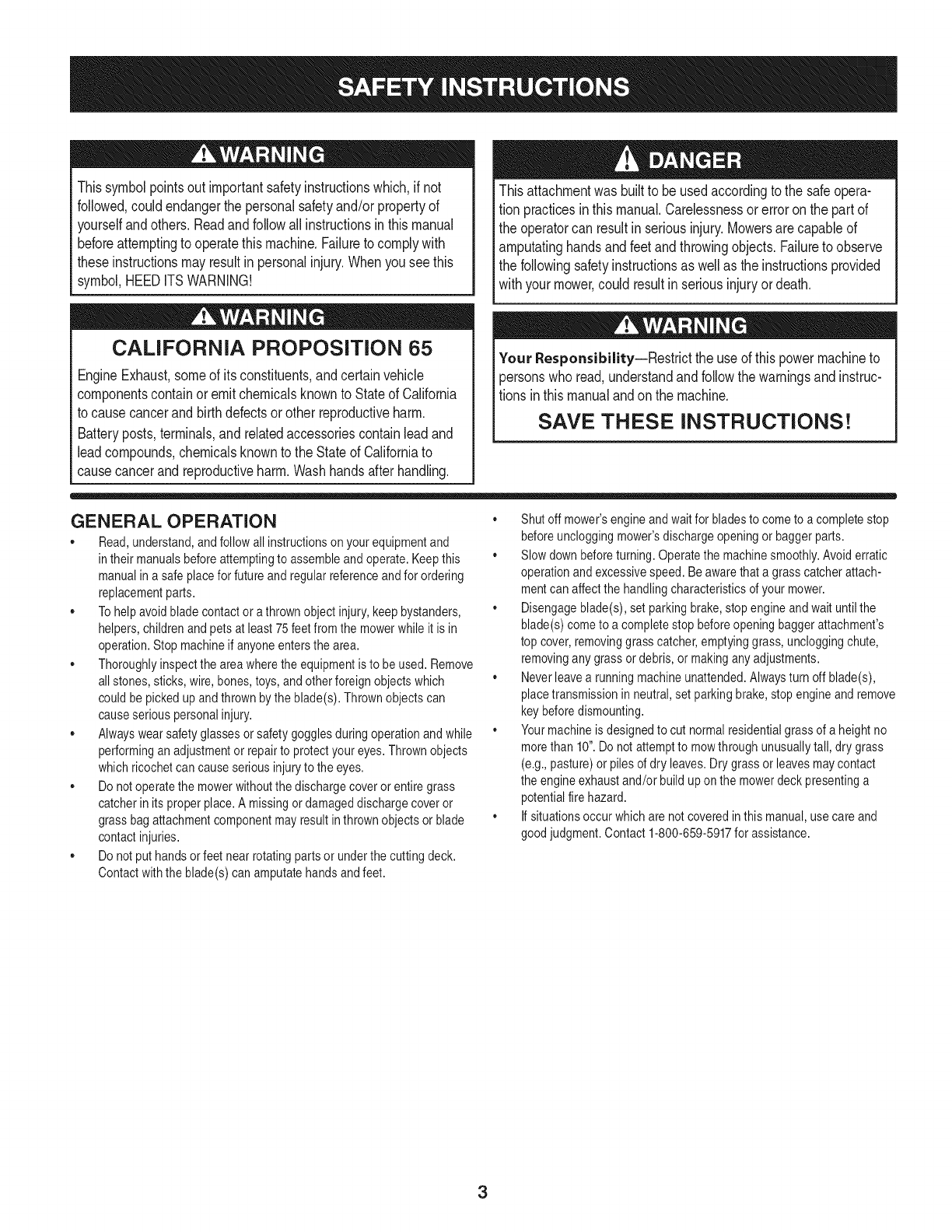
Thissymbolpointsout importantsafetyinstructionswhich,if not
followed,couldendangerthepersonalsafetyand/orpropertyof
yourselfandothers. Readandfollowall instructionsin thismanual
beforeattemptingto operatethismachine.Failureto complywith
theseinstructionsmayresultin personalinjury.Whenyou seethis
symbol,HEEDITSWARNING!
CALIFORNIA PROPOSITION 65
EngineExhaust,someof itsconstituents,andcertainvehicle
componentscontainoremit chemicalsknownto Stateof California
to causecancerandbirthdefectsorother reproductiveharm.
Batteryposts,terminals,and relatedaccessoriescontainleadand
leadcompounds,chemicalsknownto the Stateof Californiato
causecancerandreproductiveharm.Washhandsafterhandling.
Thisattachmentwas builtto be usedaccordingto the safeopera-
tion practicesinthis manual.Carelessnessor erroronthe part of
the operatorcan resultin seriousinjury.Mowersare capableof
amputatinghandsandfeetandthrowingobjects.Failureto observe
the followingsafetyinstructionsas wellas the instructionsprovided
withyour mower,could resultin seriousinjuryordeath.
Your Responsibility--Restrictthe use of this powermachineto
personswho read,understandandfollowthewarningsand instruc-
tionsin this manualandon the machine.
SAVE THESE INSTRUCTIONS!
GENERAL OPERATION
,, Read,understand,and followall instructionsonyour equipmentand
intheir manualsbeforeattemptingto assembleand operate.Keepthis
manualina safe placefor futureand regularreferenceandfor ordering
replacementparts.
,, Tohelpavoidbladecontact ora thrownobjectinjury,keepbystanders,
helpers,childrenand petsat least 75 feetfromthe mowerwhile it is in
operation.Stop machineif anyoneentersthe area.
,, Thoroughlyinspectthe areawherethe equipmentis to beused.Remove
allstones,sticks,wire, bones,toys,and otherforeignobjectswhich
couldbe pickedupand thrownby the blade(s).Thrownobjects can
causeseriouspersonalinjury.
,, Alwayswearsafetyglassesor safetygogglesduringoperationand while
performinganadjustmentor repairto protectyoureyes.Thrownobjects
whichricochetcan causeseriousinjuryto the eyes.
,, Do notoperatethe mowerwithoutthe dischargecoveror entiregrass
catcherinits properplace.A missingor damageddischargecoveror
grass bagattachmentcomponentmayresult inthrown objectsor blade
contactinjuries.
,, Do notputhands orfeet nearrotatingpartsor underthe cutting deck.
Contactwiththe blade(s) canamputatehandsand feet.
,, Shut off mower'sengineand waitfor bladesto come to a completestop
beforeuncloggingmower'sdischargeopeningor baggerparts.
,, Slow downbeforeturning. Operatethe machinesmoothly.Avoiderratic
operationandexcessivespeed.Be awarethata grasscatcherattach-
mentcan affectthe handlingcharacteristicsof your mower.
,, Disengageblade(s),set parkingbrake,stopengineand waituntil the
blade(s)cometo a completestop beforeopeningbaggerattachment's
top cover,removinggrass catcher,emptyinggrass,uncloggingchute,
removingany grass ordebris, or makinganyadjustments.
,, Neverleavea runningmachineunattended.Alwaysturn offblade(s),
placetransmissionin neutral,set parkingbrake,stopengineandremove
keybeforedismounting.
,, Your machineis designedto cut normalresidentialgrassof a heightno
morethan 10".Do notattemptto mowthroughunusuallytall, dry grass
(e.g.,pasture)or pilesof dry leaves.Drygrass orleavesmaycontact
the engineexhaustand/or buildup onthe mowerdeckpresentinga
potentialfirehazard.
,, If situationsoccur whichare notcoveredinthis manual,usecare and
good judgment.Contact 1-800-659-5917for assistance.
3
SLOPE OPERATION
Slopesare a majorfactorrelatedto lossof controlandtip-overaccidents
whichcan resultinsevere injuryordeath.Attachmentscan also affect the
stabilityof the machine.All slopesrequireextra caution.
Foryoursafety,usethe slopeguideincludedas partof this manualto
estimatetheangle of slopesbeforeoperatingthis machineona slopedor hilly
area.If theslope is greaterthan 10degreesas shownonthe slopeguide,do
notoperatethe mowerwiththe grass bagattachmentinstalledon that areaor
seriousinjurycouldresult.
DO:
1. Mowupanddownslopes,not across.Exerciseextremecautionwhen
changingdirectiononslopes.
2. Watchfor holes,ruts,bumps,rocks,or otherhiddenobjects. Uneven
terraincouldoverturnthe machine.Tall grasscan hideobstacles.
3. Useslowspeed.Choosea lowenoughspeedsetting sothat you will not
haveto stopor shift whileon the slope.Tires maylosetractionon slopes
eventhoughthe brakesarefunctioningproperly.Alwayskeepmachine
in gear whengoingdownslopesto takeadvantageof enginebraking
action.
4. Followthe manufacturer'srecommendationsfor wheelweightsor
counterweightsto improvestability.Forrecommendations,contact
1-800-659-5917.
5. Keepall movementontheslopesslowand gradual.Do notmakesud-
denchangesin speedor direction.Rapidengagementor brakingcould
causethefrontof the machineto liftand rapidlyflip overbackwards
whichcouldcauseserious injury.
6. Avoidstartingor stoppingon a slope.If tires losetraction,disengagethe
blade(s)andproceedslowly straightdownthe slope.
DO NOT:
1. Do notturnon slopesunlessnecessary;then,turn slowlyand gradually
downhill,ifpossible.
2. Do notmow neardrop-offs,ditchesor embankments.Themowercould
suddenlyturnover if a wheelis overthe edgeof a cliff,ditch,or if an
edgecaves in.
3. Do nottry to stabilizethe machineby putting yourfooton the ground.
4. Do notuse a grasscatcheronsteepslopes.
5. Do notmowon wet grass.Reducedtractioncouldcausesliding.
GENERAL SERVICE
1. Beforecleaning,repairing,or inspecting,makecertainthe blade(s)
and all movingparts havestopped. Disconnectthe spark plug wireand
ground againsttheengine to preventunintendedstarting.
2. Keep allnuts, bolts,and screwstightto be surethe equipmentis in safe
workingcondition.
3. Nevertamperwith yourmower'ssafetyinterlocksystemor othersafety
devices.Checktheir properoperationregularly.
4. Neverattemptto makeadjustmentsor repairswhilethemower'sengine
is running.
5. Grasscatchercomponentsandthe dischargecoverare subjectto wear
and damagewhichcouldexpose movingpartsor allowobjectsto be
thrown.Forsafetyprotection,frequentlycheck componentsand replace
immediatelywith originalequipmentmanufacturer's(O.E.M.)partsonly,
listed inthis manual.Useof parts whichdo not meetthe originalequip-
mentspecificationsmayleadto improperperformanceandcompromise
safety!
6. Maintainor replacesafetyand instructionlabels,as necessary.
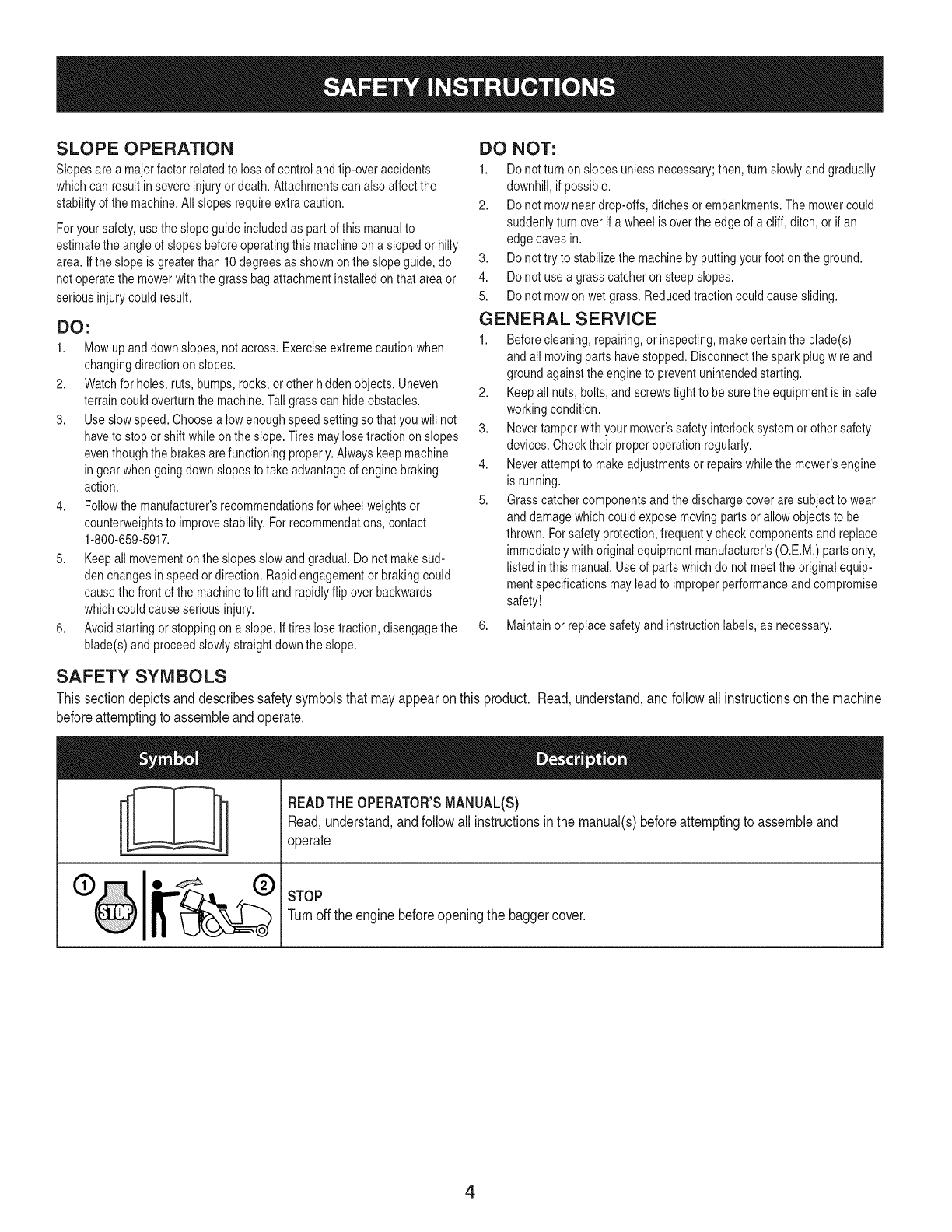
SAFETY SYMBOLS
This section depicts and describes safety symbols that may appear on this product. Read, understand, and follow all instructions on the machine
before attempting to assemble and operate.
I
I
READTHEOPERATOR'SMANUAL(S)
Read,understand,andfollowall instructionsinthe manual(s)beforeattemptingto assembleand
operate
STOP
Turnoffthe enginebeforeopeningthe baggercover.
4
05
(1)
o
_c
=o
09
g
o
E
g-
c
O
o
E
o
(:1)
o
cb
.m
(:1)
.9o
13)
.-z2
E_
¢d
(D
E)b
¢d
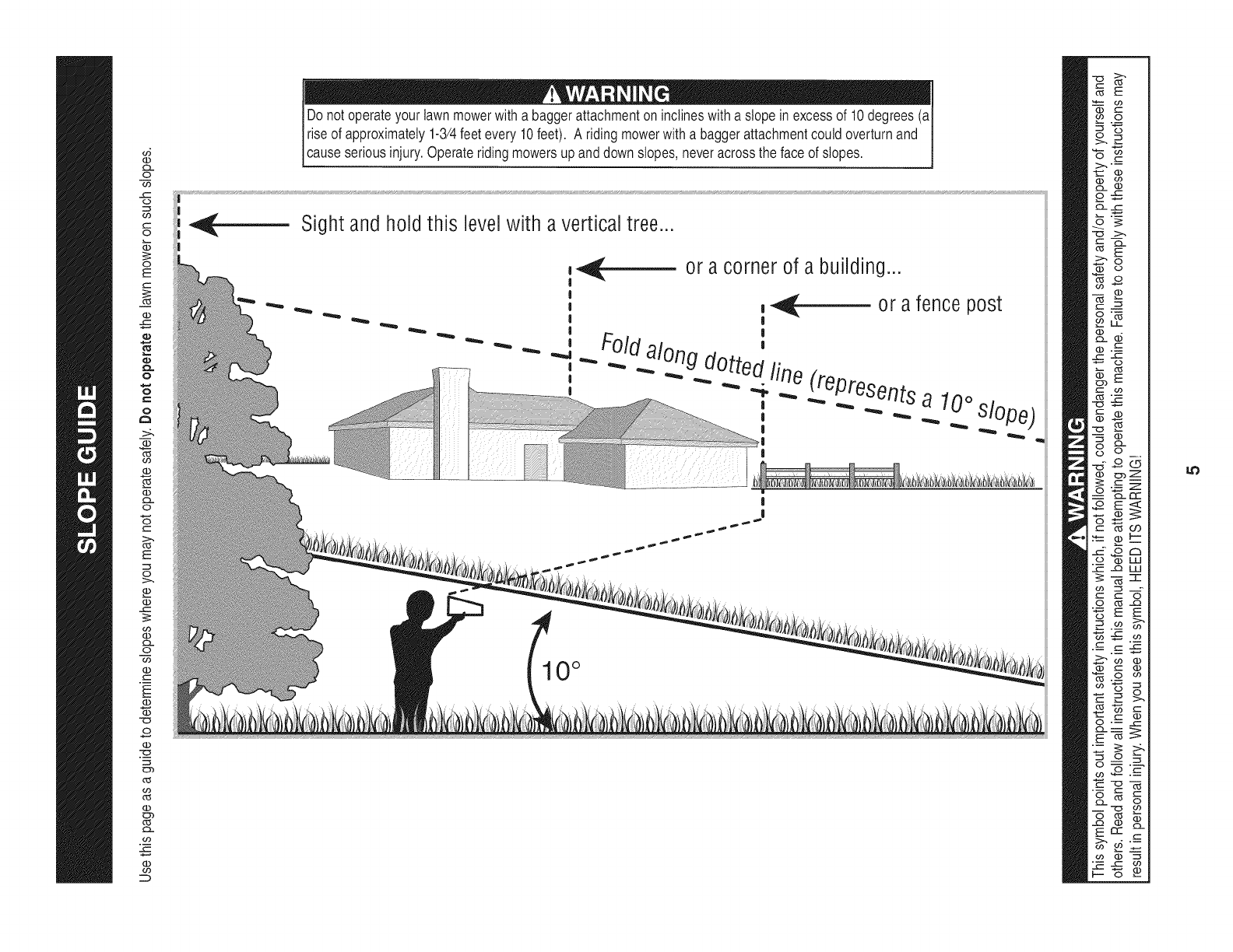
Do notoperateyour lawnmowerwitha baggerattachmentoninclineswitha slopein excessof 10degrees(aI
I riseof approximately1-3/4feetevery10feet). A ridingmowerwitha baggerattachmentcouldoverturnand
[cause seriousinjury.Operater dng mowersupanddowns opes,neveracrossthe faceof s opes.
Sight and hold this level with a vertical tree..,
or a corner of a building...
_- or a fence post
|
Foldalong d_ "
u_ed fin _epresents
_ _ e
, _ a 10°slo
10 °
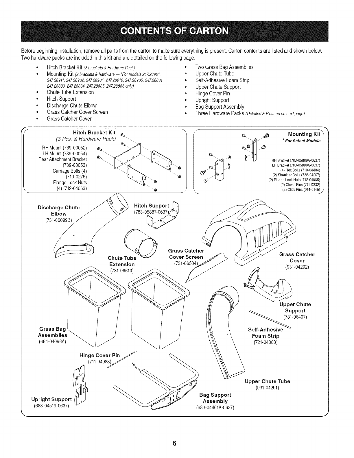
Beforebeginninginstallation,removeall partsfromthe cartonto makesureeverythingis present.Cartoncontentsarelistedand shownbelow.
Twohardwarepacksareincludedin thiskit andaredetailedon thefollowingpage.
•HitchBracketKit (3 brackets & Hardware Pack)
MountingKit (2brackets&hardware-- *Formodels24Z28901,
24Z28911, 24Z28902, 24Z28904, 24Z28919, 24Z28905, 24Z28881
24Z28883,24Z28884,24Z28885,24Z28886 only)
• ChuteTubeExtension
• HitchSupport
• DischargeChuteElbow
• GrassCatcherCoverScreen
• GrassCatcherCover
• TwoGrassBagAssemblies
UpperChuteTube
Self-AdhesiveFoamStrip
• UpperChuteSupport
• HingeCoverPin
• UprightSupport
• BagSupportAssembly
ThreeHardwarePacks(Detailed&Picturedon nextpage)
Hitch Bracket Kit
(3 Pcs. & Hardware Pack) __.\
RHMount(789-00052)
LHMount(789-00054)
RearAttachmentBracket
(789-00053)
CarriageBolts(4)
(710-0276)
FlangeLockNuts
(4)(712-04063)
¢_. _ ._ Mounting Kit"X
_ I_ l/_x_ * For Select Models
z_ _ RH Bracket (783-05889A-0637)
_ LH Bracket (783-05890A-0637)
(4) Hex Bolts (710-04484)
(2) Shoulder Bolts (738-04267)
(2) FlangeLock Nuts (712-04065)
(2)Clevis Pins (711-0332)
(2) Click Pins (914-0145)
_J
Discharge Chute
Elbow
(731-06099B)
Hitch Support _"_
(783-0_
Chute Tube@
Extension
(731-06610)
Grass Catcher
Cover Screen
(731-06504
Grass Catcher
Cover
(931-04292)
Grass Bag .
Assemblies _(664-04096A)
Hinge Cover PinJ
(711-0498__ Bag Support
Upright Support Assembly
(683-04519-0637) (683-04461A-0637)
Upper Chute
Support
Self_'06497)
Foam Strip
(721-04388)
Upper Chute Tube
(931-04291)
6

Thisgrasscollectorkitis shippedwith threehardwarepacksenclosed, Pleasecheckyourhardwarepacksagainstthe illustrationsbelow,The
quantitiesforeach itemis listedin parenthesiswhilethe part numberis listedneareachitem.
Hardware Packfor 689-00080A Hardware Pack689-00092B
1) )
710-3008
710-0276
712-04063
Hardware Pack for 689-00087
4)
710-3008
(4)
712-04063
I
©
711-0309A
I
(1)
714-0117
732-04510A
(1)
711-05049
(1)
1)
(2)
736-0176
(1)
712-04063
_(2) 723-04008
711-05063
2)
736-0204
(2)
714-04040
(1)
911-04069
(2)
712-3027
)
738-0754
(2)
7
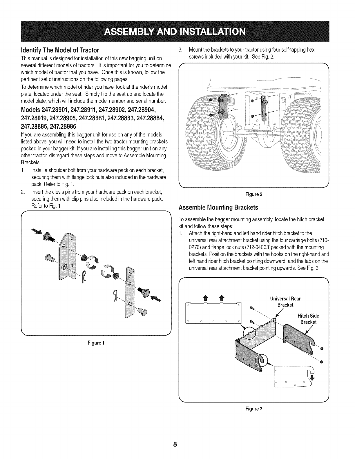
identify The Model of Tractor
Thismanualisdesignedfor installationof thisnewbagginguniton
severaldifferentmodelsof tractors. Itis importantfor youto determine
whichmodelof tractorthatyou have. Oncethisis known,followthe
pertinentsetof instructionson thefollowingpages.
Todeterminewhichmodelof rideryou have,lookat the rider'smodel
plate,locatedunderthe seat. Simplyflipthe seatupand locatethe
modelplate,whichwill includethe modelnumberandserialnumber.
Models 247.28901,247.28911,247.28902,247.28904,
247.28919,247.28905,247.28881,247.28883,247.28884,
247.28885,247.28886
Ifyou areassemblingthis baggerunitfor use onanyof themodels
listedabove,youwill needto installthe twotractormountingbrackets
packedinyour baggerkit. ifyou areinstallingthis baggerunitonany
othertractor,disregardthesestepsandmoveto AssembleMounting
Brackets.
1. Installa shoulderboltfromyourhardwarepackon eachbracket,
securingthemwithflangelocknutsalsoincludedinthehardware
pack.Referto Fig.1.
2. Insertthe clevispinsfromyourhardwarepackoneachbracket,
securingthemwithclip pinsalso includedinthe hardwarepack.
Referto Fig.1
Figure1
.
f
Mountthe bracketstoyourtractorusingfour self-tappinghex
screwsincludedwithyourkit. SeeFig.2.
Figure2
Assemble Mounting Brackets
Toassemblethe baggermountingassembly,locatethe hitchbracket
kit andfollowthesesteps:
1. Attachthe right-handandIdt handriderhitchbracketto the
universalrearattachmentbracketusingthefourcarriagebolts(710-
0276)andflangelocknuts(712-04063)packedwiththemounting
brackets.Positionthebracketswiththe hooksonthe right-handand
Idt handriderhitchbracketpointingdownward,andthe tabsonthe
universalrearattachmentbracketpointingupwards.SeeFig.3.
f
Universal Rear
Bracket
Hitch Side
Bracket
i o o
Figure3
8
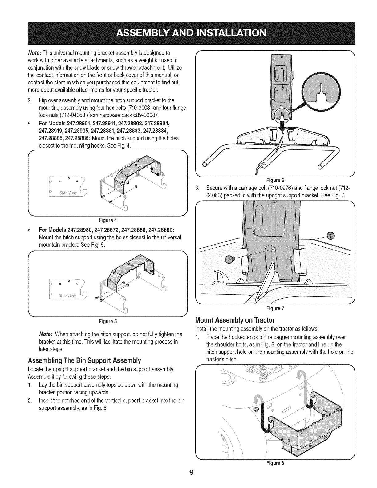
Note: Thisuniversalmountingbracketassemblyis designedto
workwithotheravailableattachments,suchas aweightkitused in
conjunctionwiththe snowbladeor snowthrowerattachment.Utilize
the contactinformationonthe frontor backcoverof this manual,or
contactthe storein whichyou purchasedthisequipmentto findout
moreaboutavailableattachmentsfor yourspecifictractor.
2. Flipoverassemblyandmountthe hitchsupportbracketto the
mountingassemblyusingfourhexbolts(710-3008)andfourflange
locknuts(712-04063)fromhardwarepack689-00087.
•For Models247.28901,247.28911,247.28902,247.28904,
247.28919,247.28905,247.28881,247.28883,247.28884,
247.28885,247.28886:Mountthe hitchsupportusingtheholes
closestto the mountinghooks.SeeFig.4.
F
Figure4
For Models 247.28980,247.28672,247.28888,247.28880:
Mountthe hitchsupportusingthe holesclosestto the universal
mountainbracket.SeeFig.5.
F
Figure6
3. Securewitha carriagebolt (710-0276)andflangelocknut (712-
04063)packedinwiththe uprightsupportbracket.SeeFig.7.
i"¸ _ ........................,
o>/
S
J
Figure5
Note: Whenattachingthe hitchsupport,do notfullytightenthe
bracketat thistime.Thiswill facilitatethe mountingprocessin
latersteps.
AssemblingThe Bin Support Assembly
Locatethe uprightsupportbracketandthe binsupportassembly.
Assembleitby followingthesesteps:
1. Laythe bin supportassemblytopsidedownwiththe mounting
bracketportionfacingupwards.
2. Insertthe notchedendof the verticalsupportbracketintothe bin
supportassembly,as in Fig.6.
9
Figure 7
Mount Assembly on Tractor
Installthe mountingassemblyon the tractoras follows:
1. Placethe hookedendsof the baggermountingassemblyover
the shoulderbolts,as inFig.8, onthe tractorandlineup the
hitchsupportholeon the mountingassemblywiththe holeonthe
tractor'shitch.
f
\
\
\\\
........ ,
Figure 8
J
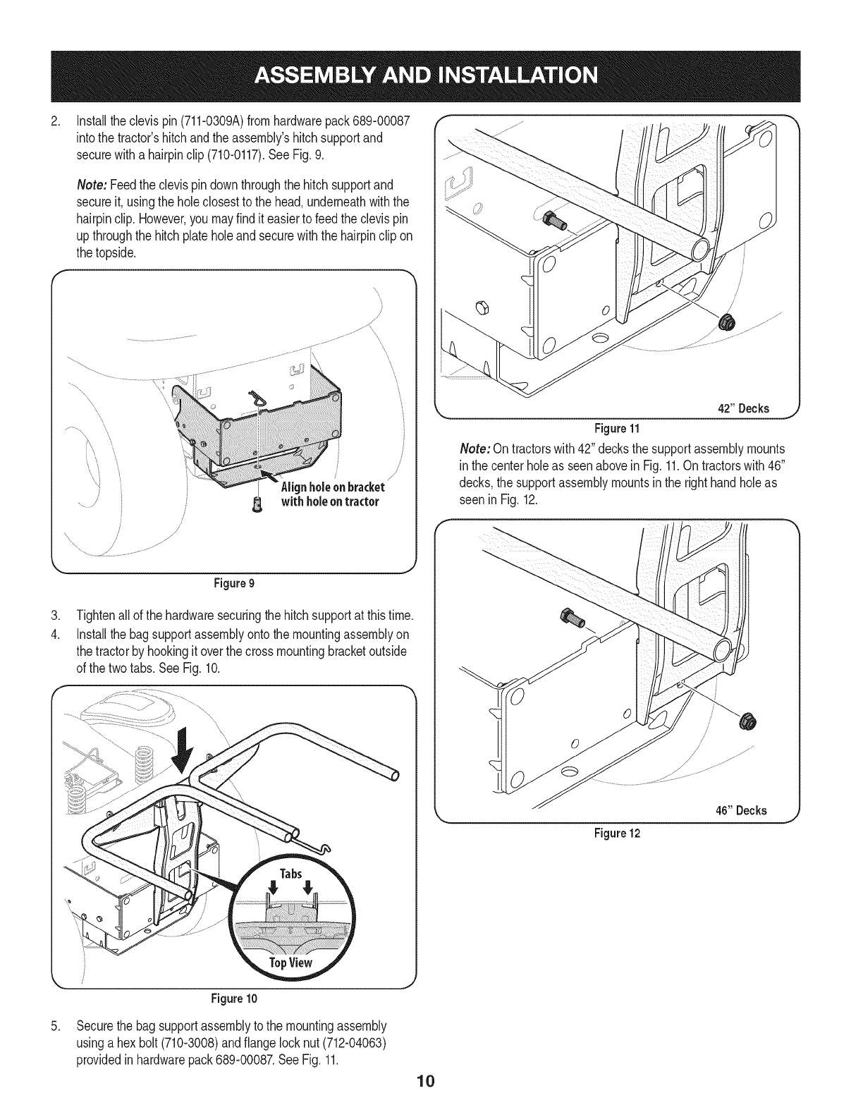
.
.
4.
Installtheclevis pin(711-0309A)fromhardwarepack689-00087
intothe tractor'shitchandthe assembly'shitchsupportand
securewitha hairpinclip (710-0117).SeeFig.9.
Note: Feedthe clevispin downthroughthe hitchsupportand
secureit, usingthe holeclosestto the head,underneathwiththe
hairpinclip.However,you mayfind it easierto feedthe clevispin
upthroughthe hitchplate holeandsecurewiththe hairpinclip on
thetopside.
\
/
J
holeOnbracket
withholeontractor
\\
Figure9
Tightenallof the hardwaresecuringthe hitchsupportat thistime.
Installthe bagsupportassemblyontothe mountingassemblyon
thetractorby hookingitoverthe crossmountingbracketoutside
of the twotabs.See Fig.10.
Figure10
/
/
L_ 4211Decks _
Figure11
Note: Ontractorswith 42" decksthe supportassemblymounts
inthe centerholeas seenaboveinFig.11.Ontractorswith46"
decks,the supportassemblymountsinthe righthandholeas
seen in Fig.12.
46" Decks
Figure12
.Securethe bagsupportassemblytothe mountingassembly
usinga hexbolt (710-3008)andflangelocknut(712-04063)
providedin hardwarepack689-00087.SeeFig.11.
10
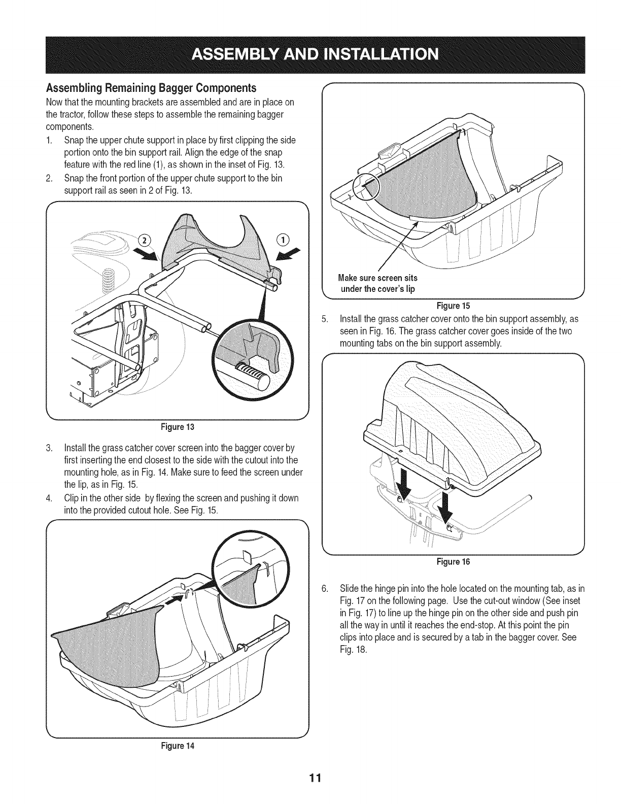
AssemblingRemaining Bagger Components
Nowthatthe mountingbracketsareassembledandare inplaceon
the tractor,followthesestepsto assemblethe remainingbagger
components.
1. Snapthe upperchutesupportinplaceby firstclippingthe side
portionontothe binsupportrail.Aligntheedgeof the snap
featurewith the redline(1),as showninthe insetof Fig.13.
2. Snapthe frontportionof the upperchutesupportto the bin
supportrailas seenin2 of Fig. 13.
f
\
Figure13
3. Installthegrasscatchercoverscreenintothe baggercoverby
first insertingthe endclosestto the sidewith thecutoutintothe
mountinghole,as inFig. 14.Makesureto feed the screenunder
the lip,as inFig. 15.
4. Clipinthe otherside byflexingthescreenand pushingitdown
intothe providedcutouthole.SeeFig.15.
Figure14
Makesurescreensits
underthe cover'slip
Figure15
Installthe grasscatchercoverontothe bin supportassembly,as
seeninFig.16.The grasscatchercovergoes insideof the two
mountingtabsonthe binsupportassembly.
Figure 16
Slidethe hingepin intothe holelocatedonthe mountingtab,as in
Fig.17onthe followingpage. Usethecut-outwindow(Seeinset
inFig. 17)to lineupthe hingepinonthe otherside andpushpin
all the wayinuntil itreachesthe end-stop.At thispointthe pin
clips intoplaceandissecuredby atab inthe baggercover.See
Fig.18.
11
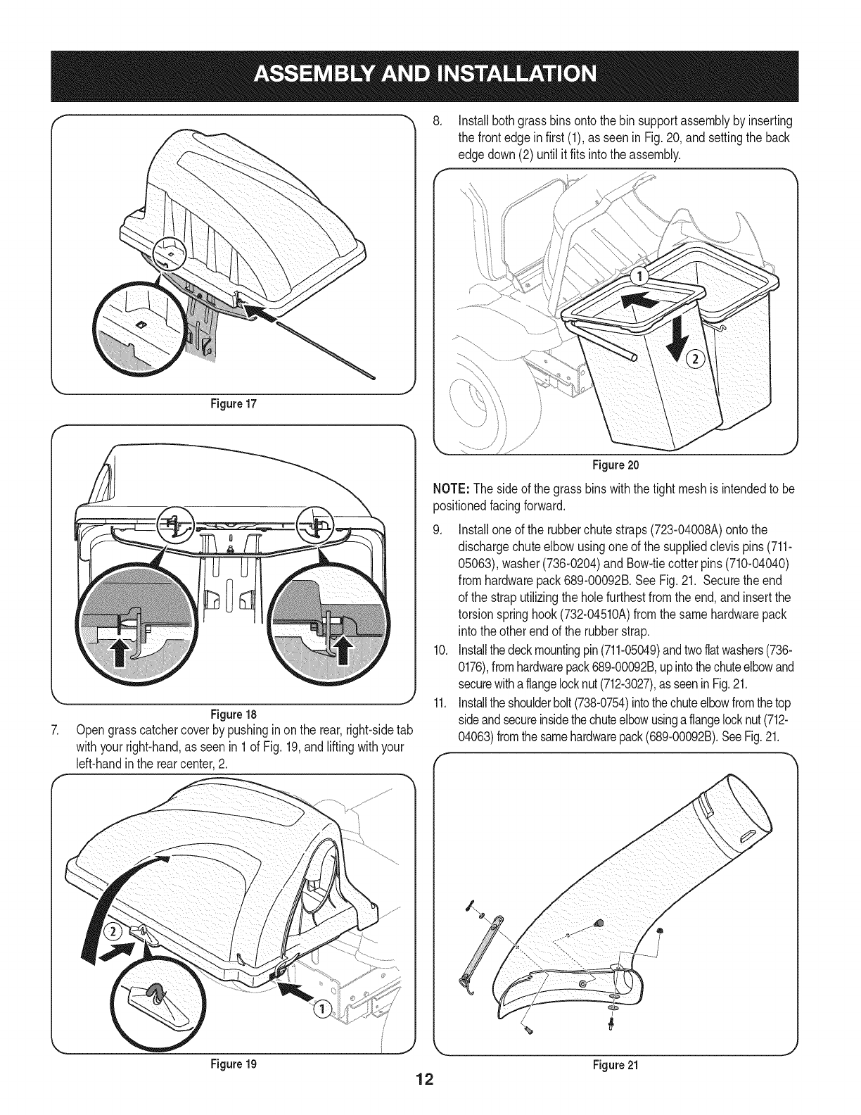
Figure17
Figure18
Opengrasscatchercoverby pushinginon the rear,right-sidetab
withyourright-hand,as seenin 1of Fig.19,andliftingwithyour
left-handinthe rearcenter,2.
8, Installbothgrassbins ontothe binsupportassemblybyinserting
the frontedgeinfirst (1),as seen in Fig.20, andsettingthe back
edgedown(2) untilit fits intothe assembly.
/
Figure 20
NOTE: The sideof the grassbins withthetight meshis intendedto be
positionedfacingforward.
g.
10.
11.
Installoneof the rubberchutestraps(723-04008A)ontothe
dischargechuteelbowusingoneof the suppliedclevispins (711-
05063),washer(736-0204)and Bow-tiecotter pins(710-04040)
fromhardwarepack689-00092B.SeeFig.21. Securetheend
of the straputilizingthe holefurthestfromthe end,and insertthe
torsionspringhook(732-04510A)fromthe samehardwarepack
into theother endof the rubberstrap.
Installthedeckmountingpin(711-05049)andtwoflatwashers(736-
0176),fromhardwarepack689-00092B,upintothechuteelbowand
securewithaflangelocknut(712-3027),asseeninFig.21.
Installtheshoulderbolt(738-0754)intothechuteelbowfromthetop
sideandsecureinsidethechuteelbowusingaflangelocknut(712-
04063)fromthe samehardwarepack(689-00092B).SeeFig.21.
Figure 19 12 Figure 21
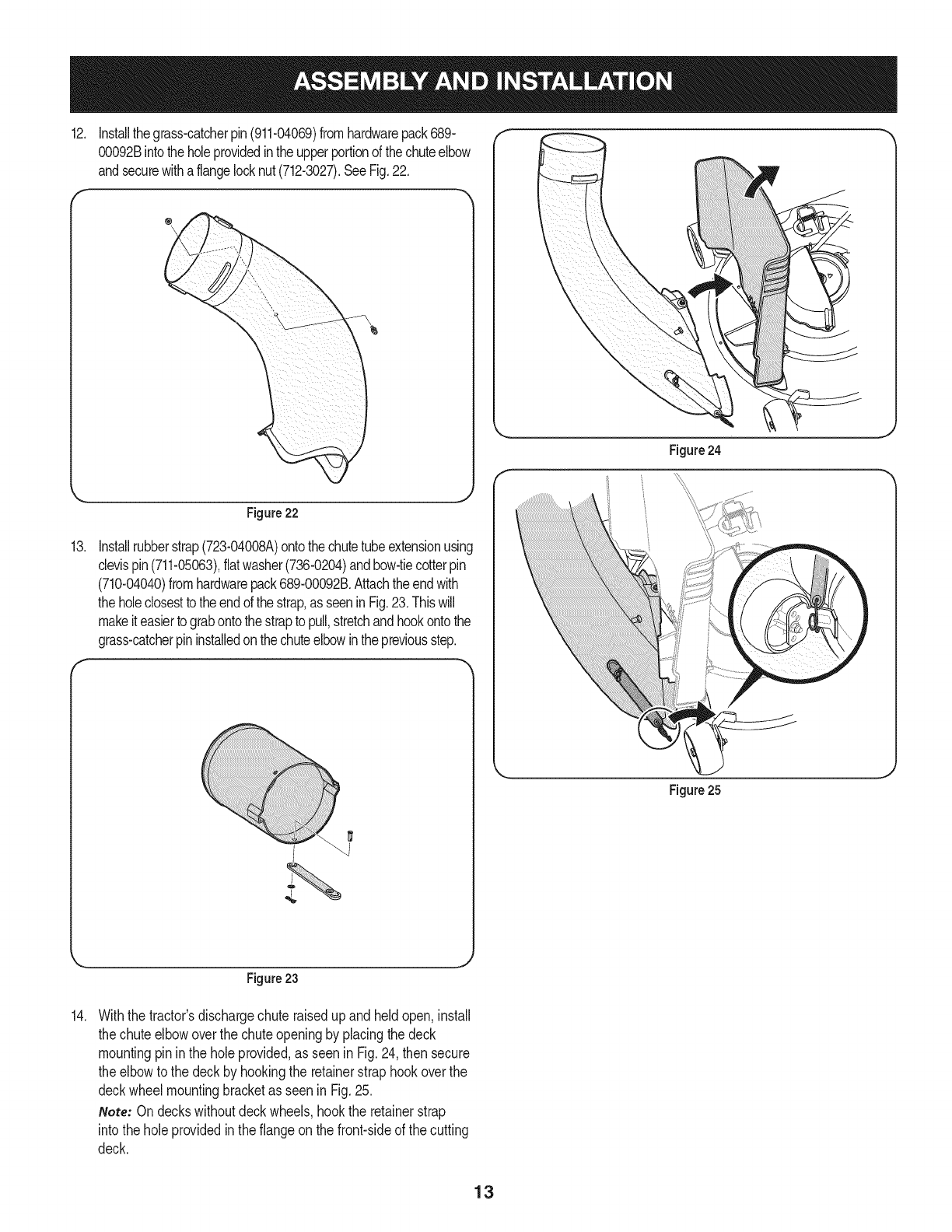
12. Installthegrass-catcherpin(911-04069)fromhardwarepack689-
00092Bintotheholeprovidedintheupperportionofthechuteelbow
andsecurewithaflangelocknut(712-3027).SeeFig.22.
f
Figure24
13.
Figure 22
Installrubberstrap(723-04008A)ontothechutetubeextensionusing
clevispin(711-05063),flatwasher(736-0204)andbow-tiecotterpin
(710-04040)fromhardwarepack689-00092B.Attachtheendwith
theholeclosestto theendofthe strap,asseenin Fig.23.Thiswill
makeit easierto grabontothestrapto pull,stretchandhookontothe
grass-catcherpininstalledonthechuteelbowinthepreviousstep.
Figure23
14. Withthe tractor'sdischargechuteraisedupandheldopen,install
the chuteelbowoverthe chuteopeningby placingthe deck
mountingpin inthe holeprovided,as seenin Fig.24,then secure
the elbowto the deckby hookingthe retainerstraphookoverthe
deckwheelmountingbracketas seenin Fig.25.
Note: Ondeckswithoutdeckwheels,hookthe retainerstrap
intothe holeprovidedin theflangeon thefront-sideof the cutting
deck.
Figure 25
13
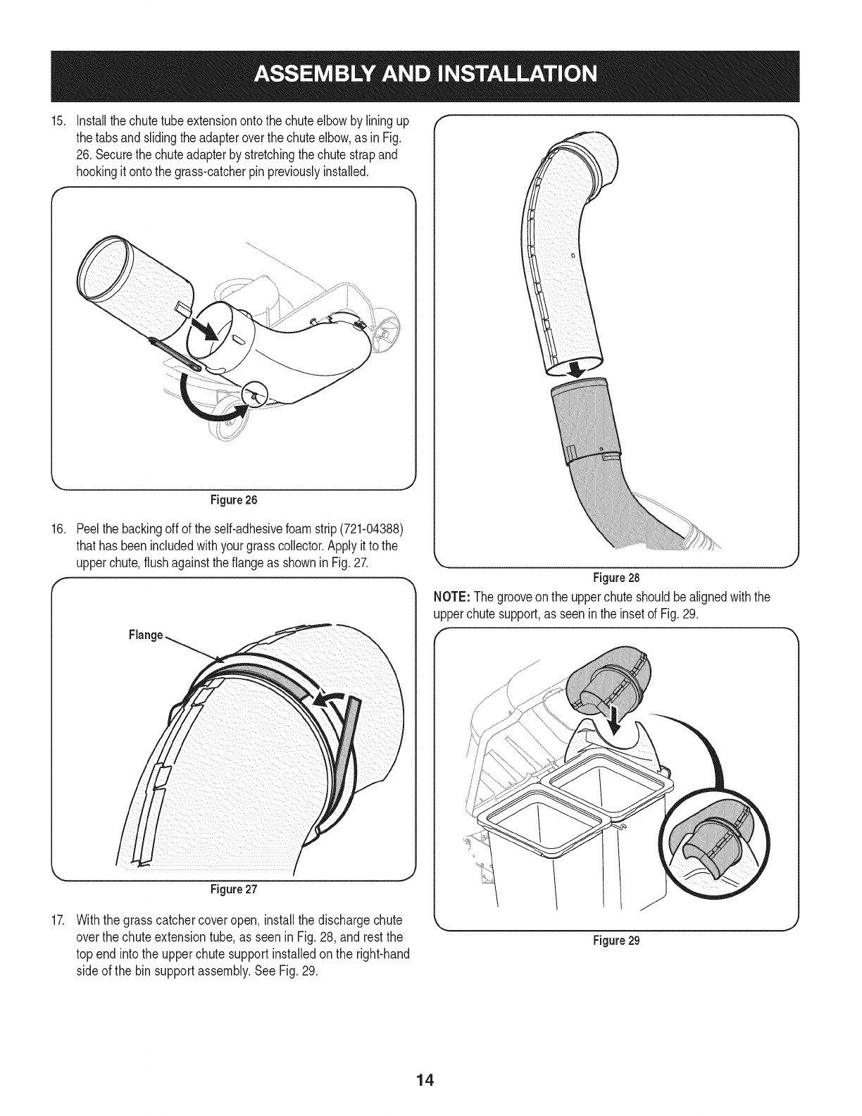
15.
16.
17.
Installthechutetubeextensionontothe chuteelbowby liningup
thetabsand slidingthe adapteroverthe chuteelbow,as inFig.
26. Securethe chuteadapterby stretchingthe chutestrapand
hookingit onto the grass-catcherpin previouslyinstalled.
Figure 26
Peelthe backingoff of the self-adhesivefoamstrip(721-04388)
thathas beenincludedwithyourgrasscollector.Applyit to the
upperchute,flushagainstthe flangeas shownin Fig.27.
Flange
I
Figure27
Withthe grasscatchercoveropen, installthe dischargechute
overthe chuteextensiontube,as seen in Fig.28, and restthe
top end intothe upperchute supportinstalledon the right-hand
side of the binsupportassembly.See Fig.29.
Figure28
NOTE: Thegrooveon the upperchuteshouldbealignedwiththe
upperchutesupport,as seenin the insetof Fig.29.
Figure 29
14
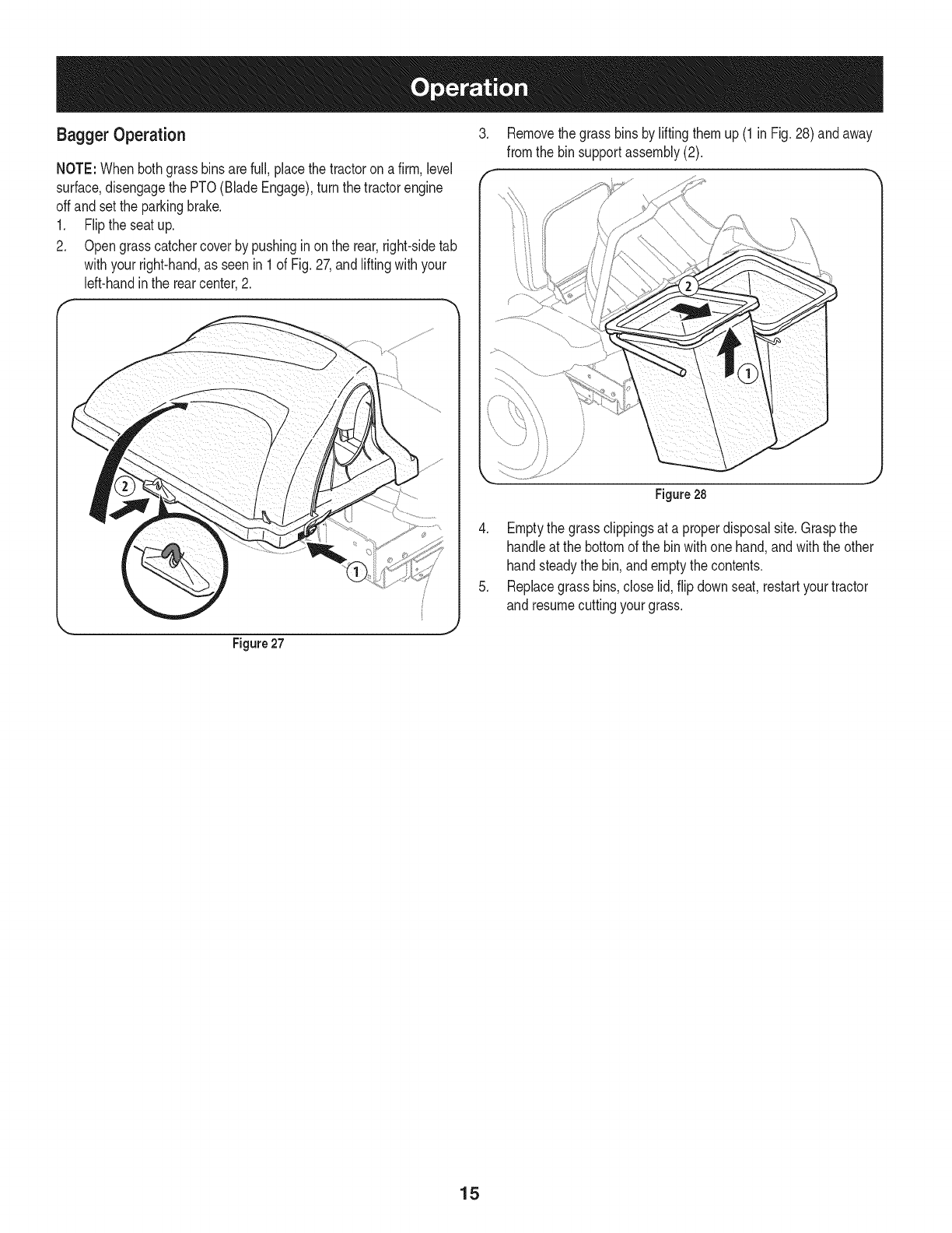
Bagger Operation 3.
f
NOTE:Whenbothgrassbinsare full,placethetractoron afirm, level
surface,disengagethe PTO(BladeEngage),turn the tractorengine
offand setthe parkingbrake.
1. Flipthe seatup.
2. Opengrasscatchercoverby pushinginon the rear,right-sidetab
withyourright-hand,as seenin 1of Fig.27,and liftingwithyour
left-handinthe rearcenter,2.
Removethe grassbinsby liftingthemup (1in Fig.28)andaway
fromthe binsupportassembly(2).
J
Figure27
Figure28
4. Emptythe grassclippingsat a properdisposalsite.Graspthe
handleat the bottomof the binwithonehand,andwiththe other
handsteadythe bin, andemptythecontents.
5. Replacegrassbins,closelid, flip downseat,restartyourtractor
and resumecuttingyourgrass.
15
2
\14
@
16

m
1
2
3
4
5
6
7
8
9
10
11
12
13
14
15
16
17
18
19
2O
21
22
23
24
25
26
27
28
29
30
31
32
33
34
35
36
37
38
39
931-04291
931-04292
731-06497
731-06504
710-0276
710-3008
711-0309A
911-04069
711-05049
711-05063
712-04063
712-3027
714-0117
714-04040
723-04008A
731-06099B
731-06610
732-04510A
736-0204
736-0176
738-0754
N/A*
N/A*
N/A*
783-05887
964-04096A
683-04461A-0637
683-04519-0637
711-04988
735-0246A
689-00101
710-04484
711-0332
712-04065
914-0145
738-04267
783-05889A-0637
783-05890A-0637
721-04388
UpperChuteAssembly
DoubleBaggerCoverAssembly
UpperChuteSupport
BaggerCoverScreen
CarriageScrew,5/16-18x 1.00"
HexHeadScrew,5/16-18x .75"
ClevisPin, .62"Dia.
Grass-catcherPin, 1/4-20
AttachmentPin,1/4x 0.66Lg.
ClevisPin,5/16x .75Lg.
FlangeLockNut,5/16-18
FlangeLockNut, 1/4-20
InternalCotterPin,.148x 3.00
Bow-TieCotterPin,72
ChuteStrap,6.00 Lg.
BaggerDischargeChute,Elbow
BaggerChuteAdapter,7 In.
TorsionSpringHook
FiatWasher,.344x.62x.033
FiatWasher,.265x.938x.120
ShoulderScrew,.437x.54
MountingBracket,RH
MountingBracket,LH
UniversalMountingBracket
UniversalSupportBracket
Grass-bagAssembly
DoubleBagSupportAssembly
VerticalSupportBracket
CoverHingePin
EndPlug
MountingBracketKit (incl.ref.22, 23, 24)
TapScrew,5/16-18x .750
ClevisPin, .50x.78
FlangeLockNut,3/8-16
Click Pin,.092x 1.64Lg.
ShoulderScrew,.625x.412
MountingBracket,RH
MountingBracket,LH
Self-AdhesiveFoamStrip
*Availableas anassemblyonly orderRef.31
17

Craftsman Total Garantia
CraftsmanSiesteproductofalla debidoa undefectode materialo manode obradentrode unaSoa partirde la fechadecompra,el retornoa
cualquierfiendaSearso cualquierotra Craftsmande salidaenlos EstadosUnidosparala sustituci6ngratuita.
EstagaranfiacubreQnicamentedefectosde materialy manodeobra. Searsnopagar&por:
• Sustituci6ndelas bolsas,quesonfungiblesquepuedenIlevara cabo apartir dela utilizaci6nnormalen elperiodode
garanfia.
• Las reparacionesnecesariasa causade accidenteo el fracasoparaoperaro mantenerel productode acuerdocon todaslas
instruccionessuministradas.
Estagarantiaseaplicaa s61o90dias si esteproductoes utilizadocadavezcon finescomercialeso alquiler.
Estagaranfias61ose aplicamientrasesteproductose utilizaen los EstadosUnidos.
Estagaranfiale otorgaderechoslegalesespecificos,y ustedtambi_npuedetenerotrosderechosquevariande unestadoa otro.
Sears, Roebuck and Co., Hoffman Estates, IL 60179
© SearsBrands,LLC 18
Lapresenciadeeste sirnboloindicaque setratade instrucciones
irnportantesde seguridadquese debenrespetarparaevitar
ponerenpeligrosu seguridadpersonaly/o materialy lade otras
personas.Leay siga todaslas instruccionesdeestemanualantes
de poneren funcionarnientoestarn_quina.Si no respetaestas
instruccionespodriaprovocarlesionespersonales.Cuandoveaeste
sirnbolo,ipresteatenci6na la advertencia!
PROPOSICION 65 DE CALIFORNIA
Elescapedel motordeesteproducto,algunosde suscornponentes
y algunoscornponentesdelvehiculocontieneno liberansustancias
quirnicasqueelestadodeCaliforniaconsideraque puedenproducir
c_ncer,defectosde nacirnientouotrosproblernasreproductivos.
Losbornesdela bateriay los accesoriosafinescontienenplornoy
cornpuestosde plorno,sustanciasquirnicasque segOnIo estableci-
do pot el Estadode Californiacausanc_ncery da_osenel sisterna
reproductivo.Ldveselas manos despu_sde estaren contacto
con estoscomponentes.
Estarn&quinarueconstruidaparaseroperadadeacuerdocon
las reglasde seguridadcontenidasenestemanual.AI igualque
concualquiertipo deequipornotorizado,undescuidoo errorpor
partedeloperadorpuedeproducirlesionesgraves.Estarn&quina
es capazde arnputarrnanosy piesy dearrojarobjetoscon gran
fuerza.Deno respetarlas instruccionesde seguridadsiguientesse
puedenproducirlesionesgraveso larnuerte.
Su responsabilidad--Restrinja el usode estarn_quina
rnotorizadaa las personasque lean,cornprendany respetenlas
advertenciase instruccionesqueaparecenen estemanualy en la
rn_quina.
iGUARDEESTASINSTRUCCIONES!
Fundonamiento general
1. Lea, comprenda y respete todas las instrucciones que figuran
en el equipo yen los manuales antes de intentar armarlo y
hacerlo funcionar. Guarde este manual en un lugar seguro
para consultas futuras y peri6dicas, asi como para solicitar
repuestos.
2. Para ayudar a evitar una lesidn pot contacto con las cuchillas
o con un objeto que sea arrojado, mantenga a las personas
que observan, a los ayudantes, ni_os y mascotas alejados a no
menos de 25 metros de la m_quina mientras est_ funcionando.
Detenga la m_quina si alguien entra en la zona.
3. Revise minuciosamente el _irea donde se va a usar el equipo.
Retire todas las piedras, palos, cables, huesos, juguetes y otros
objetos extrahos que podrian ser recogidos y arrojados por la
accidn de las cuchillas. Los objetos arrojados por la m_quina
pueden causar lesiones graves.
4. Para protegerse los ojos, utilice siempre galas o lentes de
seguridad mientras opera la m&quina o mientras la ajusta
o repara. Los objetos arrojados que rebotan pueden causar
lesiones oculares graves.
5. Nunca opere la cortadora de c_sped sin tenet bien colocada
la cubierta de descarga o el colector de c_sped. Si falta o
est_ da_ada la cubierta de descarga oun componente del
accesorio embolsador puede resultar en lesiones por contacto
con la cuchilla o con objetos arrojados.
6. No ponga las manos ni los pies cerca de las piezas rotatorias ni
debajo de la plataforma de corte. El contacto con las cuchillas
puede resultar en la amputacidn de una mano o pie.
7. Apague el motor de la cortadora de c_sped y espere que
las cuchillas se detengan totalmente antes de desbloquear
la abertura de descarga de la cortadora o las piezas de la
embolsadora.
8. Reduzca la velocidad antes de girar. Opere la m_quina de
forma pareja. Evite el funcionamiento err_tico y la velocidad
excesiva. Tenga en cuenta que el accesorio colector de c6sped
puede afectar las caracteristicas de manejo de su cortadora.
Fundonamiento en pendientes
Las pendientes son un factor importante en los accidentes
ocasionados por p_rdida de control y vuelcos que pueden causar
lesiones graves e incluso la muerte. Los accesorios tambien pueden
afectar la estabilidad de la m_iquina. La operaci6n en pendiente
requiere mayor precaucidn.
Para seguridad, use el medidor de pendientes que se incluye como
parte de este manual para estimar el _ingulo de la pendiente antes
de hacer funcionar la m_iquina en una zona inclinada. Si la pendiente
es mayor a 10 grados en el medidor, no opere la cortadora con el
accesorio embolsador en ese sector, pues podria causar lesiones
graves.
I-lagaIo siguiente:
1. Corte hacia arriba y abajo de las pendientes, no en forma
transversal. Tenga sumo cuidado al cambiar de direcci6n en
una pendiente.
2. Est_ atento a los hoyos, surcos, baches, rocas, u otros objetos
ocultos. El terreno desnivelado puede voltear la m_quina. El
pasto alto puede ocultar obst_iculos.
3. Conduzca a baja velocidad. Elija una velocidad Io
suficientemente baja como para no tenet que detenerse
o cambiar de marcha mientras est,1 en la pendiente. Los
neum&ticos pueden perder tracci6n en las pendientes aun
cuando los frenos funcionen correctamente. Mantenga
la m_quina siempre en velocidad cuando desciende una
pendiente, para poder frenar con el motor.
19
4. Siga las recomendaciones del fabricante sobre pesos y
contrapesos de las ruedas, para mejorar la estabilidad.
5. Haga que todos los movimientos en las pendientes sean
lentos y graduales. No cambie repentinamente la velocidad
ni la direcci6n. Un frenado o cambio de velocidad repentinos
pueden causar que el frente de la m_iquina se levante y d_ una
voltereta hacia atr_is, Io que podria causar lesiones graves.
6. Evite arrancar o detenerse en una pendiente. Si los neum_iticos
pierden traccidn, desenganche las cuchillas y descienda
lentamente la pendiente.
No haga Iosiguiente:
I. No gire en una pendiente a menos que sea imprescindible. De
ser posible, gire lenta y gradualmente cuesta abajo.
2. No corte el c_sped cerca de barrancos, zanjas o terraplenes. La
cortadora de c_sped podria volcarse repentinamente si una de
las ruedas estuviera sobre el borde de un acantilado o zanja, o
si un borde se desmoronara.
3. No intente estabilizar la m_iquina poniendo el pie en el suelo.
4. No utilice un colector de c_sped en pendientes empinadas.
5. No corte el c_sped humedo. Una reducci6n en tracci6n puede
causar derrapes.
Sewido general
I. Antes de limpiar, reparar o inspeccionar la m_quina,
compruebe que las cuchillas y todas las piezas m6viles se
hayan detenido. Desconecte el cable de la bujia y p6ngalo
haciendo masa contra el motor para evitar que arranque
accidentalmente.
2. Mantenga todas las tuercas, pernos y tornillos bien ajustados
para asegurarse de que el equipo est,1 en condiciones seguras
de operaci6n.
3. Nunca intente violar el sistema de bloqueo de seguridad u
otros mecanismos de seguridad de la cortadora. Controle
peri6dicamente que funcionan correctamente.
4. No intente nunca hacer ajustes o reparaciones a la cortadora
mientras el motor est,1 en marcha.
5. Los componentes del colector de c_sped y la cubierta de
descarga est_fin sujetos a desgaste y dahos que podrian dejar
expuestas piezas que se mueven o permitir que se arrojen
objetos. Para proteger su seguridad, verifique frecuentemente
todos los componentes y reempl_icelos inmediatamente
unicamente con piezas de los fabricantes del equipo original
(O.E.M.) indicados en este manual. El uso de piezas que no
cumplen con las especificaciones del equipo original puede
resultar en rendimiento inadecuado y puede poner en peligro
la seguridad.
6. Mantenga o reemplace las etiquetas de seguridad y de
instrucciones segun sea necesario.
Simbolosde seguridad
En esta p_gina se presentan y describen los simbolos de seguridad que pueden aparecer en este producto. Lea, entienda y cumpla todas las
instrucciones incluidas en la m_quina antes de intentar armarla y utilizarla.
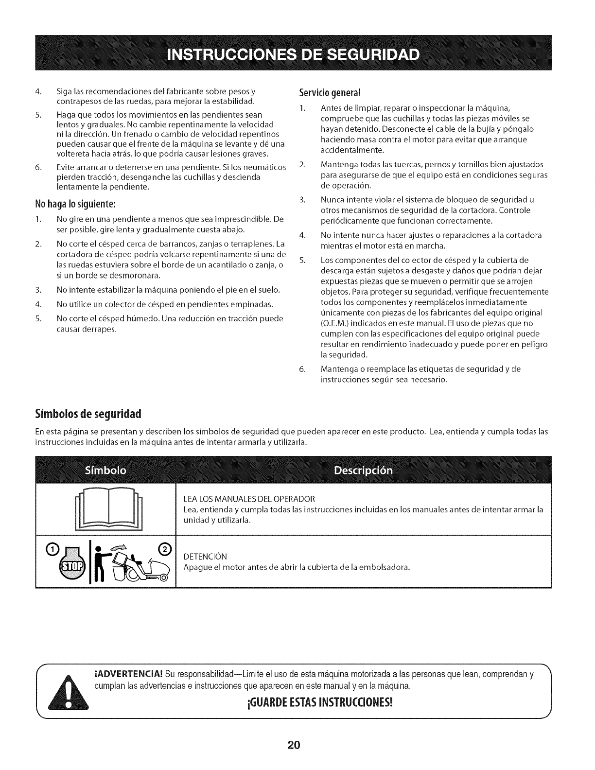
LEA LOS MANUALES DEL OPERADOR
Lea, entienda y cumpla todas las instrucciones incluidas en los manuales antes de intentar armar la
unidad y utilizarla.
DETENCION
Apague el motor antes de abrir la cubierta de la embolsadora.
IADVERTENCIA! Su responsabilidad--Limiteel usode estam&quinamotorizadaalas personasque lean,comprendany
cumplanlasadvertenciase instruccionesqueapareceneneste manualyen lam&quina.
iGUAI DEESTASINSTRLICCIONES!
2O
"O
(:D
"(1)
CD
e5
O
e5
O
O
E
o
o,.5
e5 CD
.___-_
Ob_
,e5 ¢O
_g
CD
.o_
_g
I
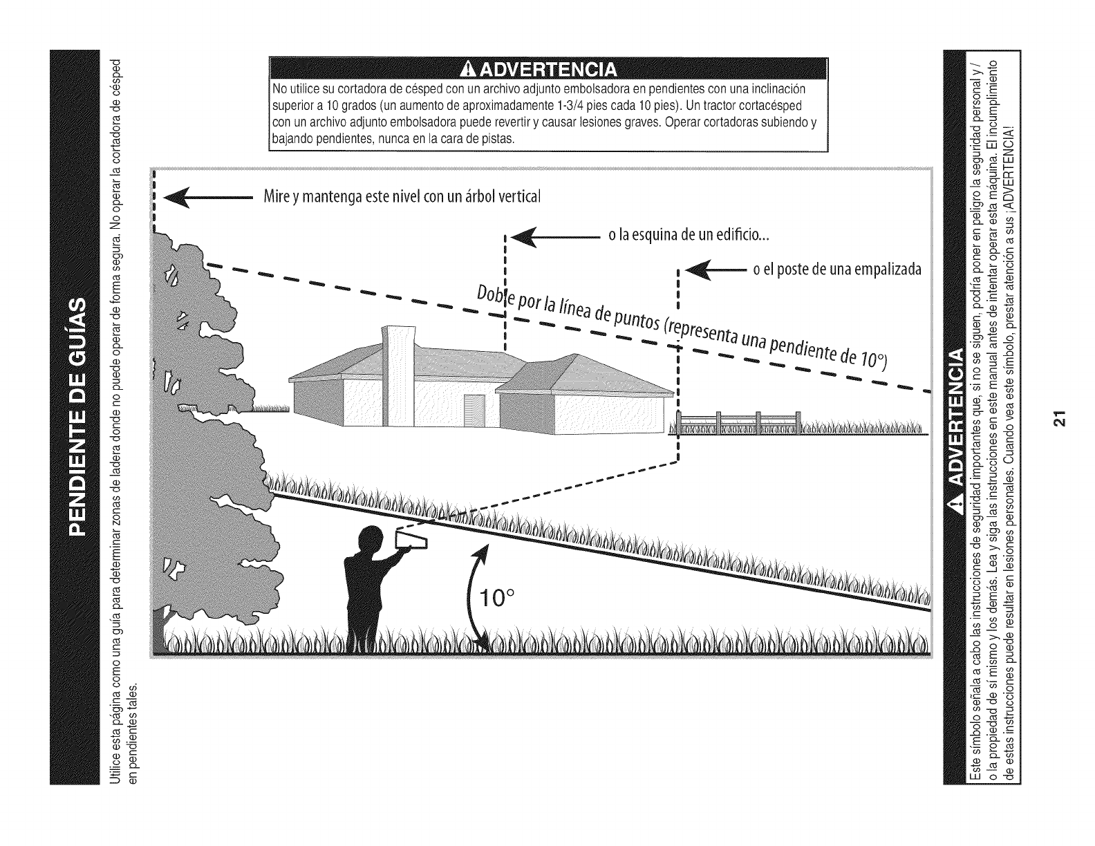
No utilicesu cortadorade cespedcon unarchivoadjuntoembolsadoraen pendientescon unainclinacion
superiora 10grados(un aumentodeaproximadamente1-3/4piescada 10pies).Untractorcortacesped
conunarchivoadjuntoembolsadorapuederevertiry causarlesionesgraves.Operarcortadorassubiendoy
baandopendentes,nuncaen a carade pstas.
Mirey mantengaestenivel conun _rbol vertical
,_ ola esquinade un edificio...
I
|
, __ 0 el p0stede una empalizada
I |
bl '
Do epot lalineade
_" "_ -.. PUntos(top
," _ "" ._... ._ ._ _.,resenta._una_pendientede
-- _. .. 700)
I
|
|
|
10°
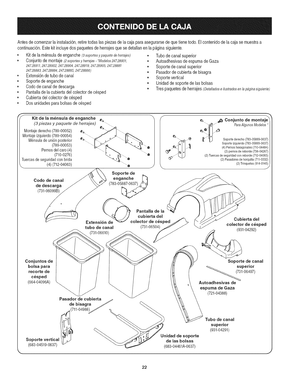
Antesdecomenzarla instalaci6n,retiretodaslas piezasdela cajaparaasegurarsedequetienetodo,Elcontenidodela cajase muestraa
continuaci6n,Estekit incluyedos paquetesde herrajesquese detallanen lap&ginasiguiente,
• Kit de lam_nsuladeenganche(8soportesy paquete de herrajes)
Conjuntode montaje(2soportesyherrajes-*Modelos24728901,
24Z28911,24Z28902,24Z28904,24Z28919,24Z28905,24Z28881
24Z28883,24Z28884,24Z28885,24Z28886)
• Extensi6ndetubede canal
• Soportede enganche
• Codedecanalde descarga
• Pantalladela cubiertadelcolectordec_sped
• Cubiertadelcolectorde cesped
• Dosunidadesparabolsasdecesped
Tubedecanalsuperior
AutoadhesivasdeespumadeGaza
Soportedecanalsuperior
Pasadorde cubiertade bisagra
Soportevertical
Unidadde soportede las bolsas
Trespaquetesde herrajes(Oetalladoseilustradosenlap4ginasiguiente)
Kit de la rn_nsula de enganche
(3 piezas y paquete de herrajes) _'_'"....
Montajederecho(789-00052)
Montajeizquierdo(789-00054)
Mensuladeuni6n posterior
(789-00053)
Pernosdel care (4)
(710-0276)
Tuercasde seguridadconbrida
(4)(712-04063)
Code de canal
de descarga
(731-06099B)
Soporte de
enganche _'_
(783-05_
PantalJade la
tube de canal (731-06504)
(731-06610)
Conjunto de montaje-'X
__'_J'_ ParaAlgunosModelos*
__ Soportederecho (783-05889-0637)
Soporte izquierdo(783-05889-0637)
(4) Pernos hexagonales (710-04484)
(2) pernos de reborde (738-04267)
(2)Tuercas de seguridad con reborde (712-04065)
(2) Pasadores de horquilla (711-0332)
(2) Trinquetes(914-014_
Cubierta del
colector de c_sped
(931-04292)
Conjuntos de
bolsa para
recorte de
c_sped
(664-04096A) _
Pasador de cubierta_
de bisagra _ _,._
..(711-04988)_" _ "_
Soportevertical f37" aelasbolsas
(683-04519-0637) _._,'_'_ (683-04461A-0637)
Soporte de canal
_7_3 superi°r
1-06497)
Autoadhesivas de
espuma de Gaza
(721-04388)
Tube de canal
superior
(931-04291)
J
22
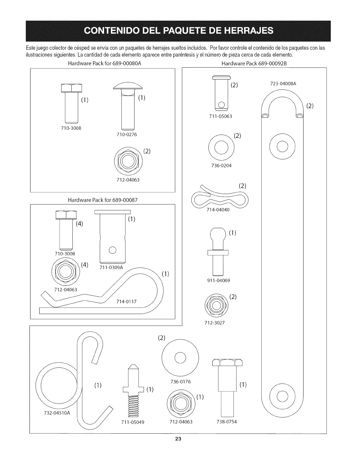
Estejuegocolectorde c6spedse enviacon unpaquetesde herrajessueltosinduidos. Porfavorcontroleel contenidode los paquetescon las
ilustracionessiguientes.Lacantidadde cadaelementoapareceentrepar6ntesisy el n0merodepiezacercadecadaelemento.
Hardware Packfor 689-00080A Hardware Pack689-00092B
1) )
710-3008
710-0276
@(2)
712-04063
Hardware Pack for 689-00087
(4)
710-3008
(4)
712-04063
I
©
711-0309A
I
(1)
714-0117
732-04510A
(1)
711-05049
(1)
1)
(2)
736-0176
(1)
712-04063
_(2) 723-04008_
711-05063
(2)
736-0204
(2)
714-04040
(1)
911-04069
(2)
712-3027
(1)
738-0754
(2)
23
Identifiqueel modelo de tractor
Estemanualest,.dise_adoparala instalaci6ndeestaunidadde
ensacadonuevasen variosdiferentesrnodelosde tractores.Es
irnportanteparaustedparadeterrninarcu_.les el rnodelodetractor
queustedtiene.Unavezqueestose conoce,sigael conjuntode
instruccionespertinentesen las p_.ginassiguientes.
Paradeterrninarqu_rnodelodepilotoquetiene,rnirara la placadel
rnodelodelciclista,que seencuentradebajodelasiento.Sirnplernente
darla vueltaal asientohaciaarribay busquela placadelrnodelo,que
incluir_,el nOrnerode rnodeloy nOrnerodeserie.
Tractoresde la serie 247.28901,247.28911,247.28902,
247.28904,247.28919,247.28905,247.28881,247.28883,
247.28884,247.28885,247.28886
Siest&rnontandoestaunidadernbolsadoraparasu usoencualquiera
de losrnodelosanteriores,tendr&queinstalareltractorde dos
soportesde rnontajeenvasadoen su kitde laernbolsadora.Siva a
instalarestaunidadernbolsadoraencualquierotto tractor,hayque
saltarseesospasosy pasara rnontarlos soportesde rnontaje.
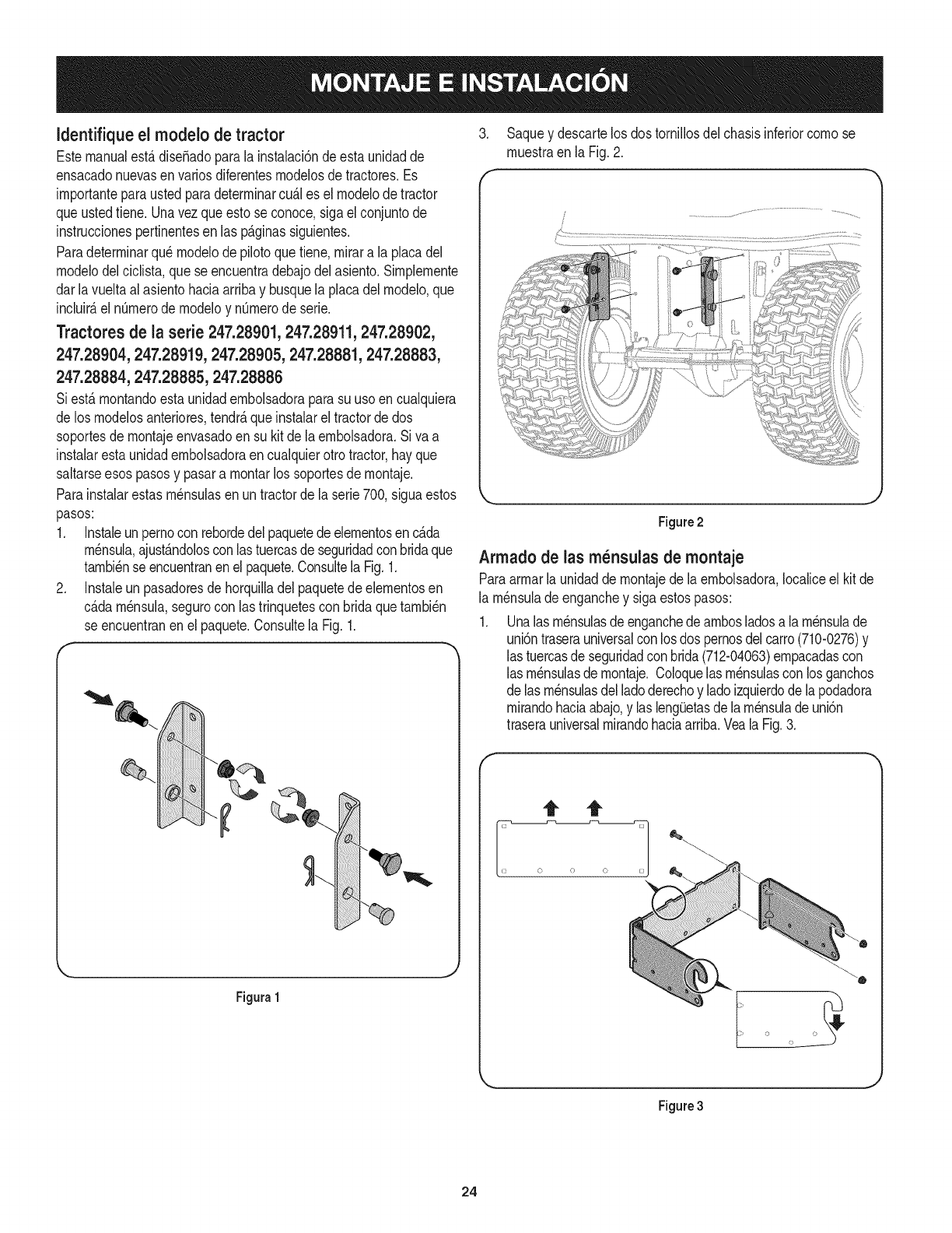
Parainstalarestas rn_nsulasen untractorde la serie700,siguaestos
pasos:
1. Instaleunpernoconrebordedelpaquetedeelernentosen c_.da
rn_nsula,ajust_.ndoloscon lastuercasde seguridadcon bridaque
tarnbi_nse encuentranenel paquete.Consultela Fig.1.
2. Instaleunpasadoresdehorquilladelpaquetedeelernentosen
c_.darn_nsula,segurocon las trinquetescon bridaquetarnbi_n
se encuentranen el paquete.Consultela Fig.1.
J
Figura1
3. Saquey descartelos dostornillosdel chasisinferiorcornose
rnuestraen la Fig.2.
f
Figure2
Armado de las m_nsulas de montaje
Paraarrnarla unidadde rnontajedela ernbolsadora,Iocaliceel kit de
la rn_nsulade enganchey siga estospasos:
Unalas rnensulasde enganchede arnbosladosala rnensulade
uni6ntraserauniversalconlosdos pernosdelcarro(710-0276)y
las tuercasde seguridadcon brida(712-04063)ernpacadascon
las rn_nsulasde rnontaje.Coloquelas rn_nsulascon losganchos
de lasrn_nsulasdelladoderechoy ladoizquierdodela podadora
rnirandohaciaabajo,y las leng_Jetasdela rn_nsulade uni6n
traserauniversalrnirandohaciaarriba.Veala Fig.3.
Figure3
24
Nora:Estaunidaddelarn_nsulade rnontajeuniversalest,.disefiadao
parafuncionarconotrosaccesorios,cornoeseljuegodecontrapesos
quese usajuntoconlacuchillaparanieveoelaccesorioquitanieve.
Utilicelainforrnaci6ndecontactodela tapadeestemanual,o
cornuniqueseconlatiendadondeadquiri6elequipo,paraobtenerrn_.s
inforrnaci6nsobrelosaccesoriosdisponiblesparasutractorenparticular.
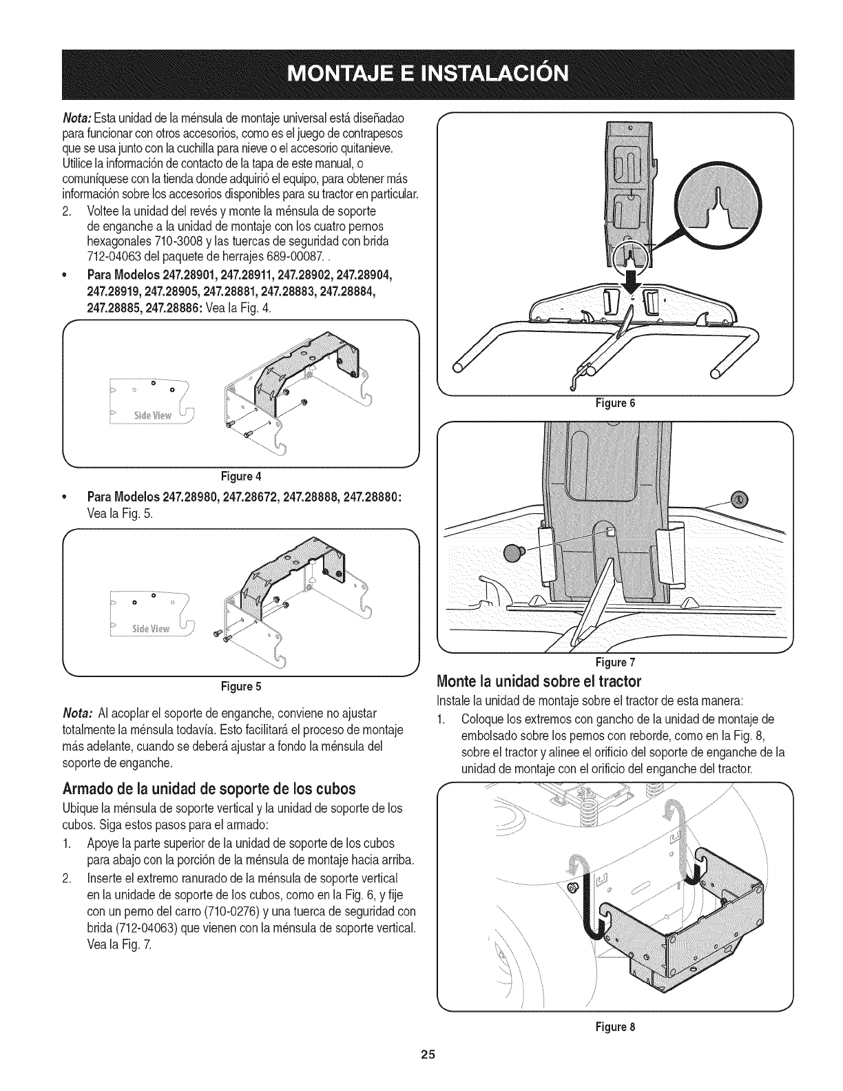
2. Volteela unidaddel revesy montela rn_nsulade soporte
deenganchea la unidadde rnontajecon los cuatropernos
hexagonales710-3008y lastuercasdeseguridadcon brida
712-04063del paquetedeherrajes689-00087..
•ParaModelos247.28901,247.28911,247.28902,247.28904,
247.28919,247.28905,247.28881,247.28883,247.28884,
247.28885,247.28886:VealaFig.4.
f
_:!;;;_i!!!;;i;;i;!!;iiiiiiiif¸¸¸¸¸¸¸_¸_¸¸¸¸¸_i!;!!
:o/
}
Figure4
ParaModelos247.28980,247.28672,247.28888,247.28880:
Veala Fig.5.
Figure 5
Neta: AI acoplarel soportedeenganche,convienenoajustar
totalrnentela rn_nsulatodavia.Estofacilitate,el procesode rnontaje
rn_.sadelante,cuandose deber_,ajustara rondola rn_nsuladel
soportedeenganche.
Armadode la unidad de soporte de los cubos
Ubiquela rn_nsulade soporteverticaly la unidadde soportedelos
cubos.Sigaestos pasosparael arrnado:
1. Apoyelaparte superiorde la unidadde soportede los cubos
paraabajocon la porci6nde larn_nsuladernontajehaciaarriba.
2. Inserteel extrernoranuradodela rn_nsulade soportevertical
enla unidadedesoportede los cubos,cornoenla Fig.6, y fije
con unpemodel carro(710-0276)y unatuercade seguridadcon
brida(712-04063)quevienenconla rn_nsulade soportevertical.
Veala Fig.7.
Figure 6
Figure7
Monte la unidad sobre el tractor
Instalela unidaddernontajesobreel tractorde estarnanera:
1. Coloquelosextrernosconganchode launidadde rnontajede
ernbolsadosobrelos pernoscon reborde,cornoenla Fig.8,
sobreel tractory alineeel orificiodel soportedeenganchede la
unidadde rnontajeconel orificiodelenganchedel tractor.
....s
................................................
'x
\
Figure 8
25
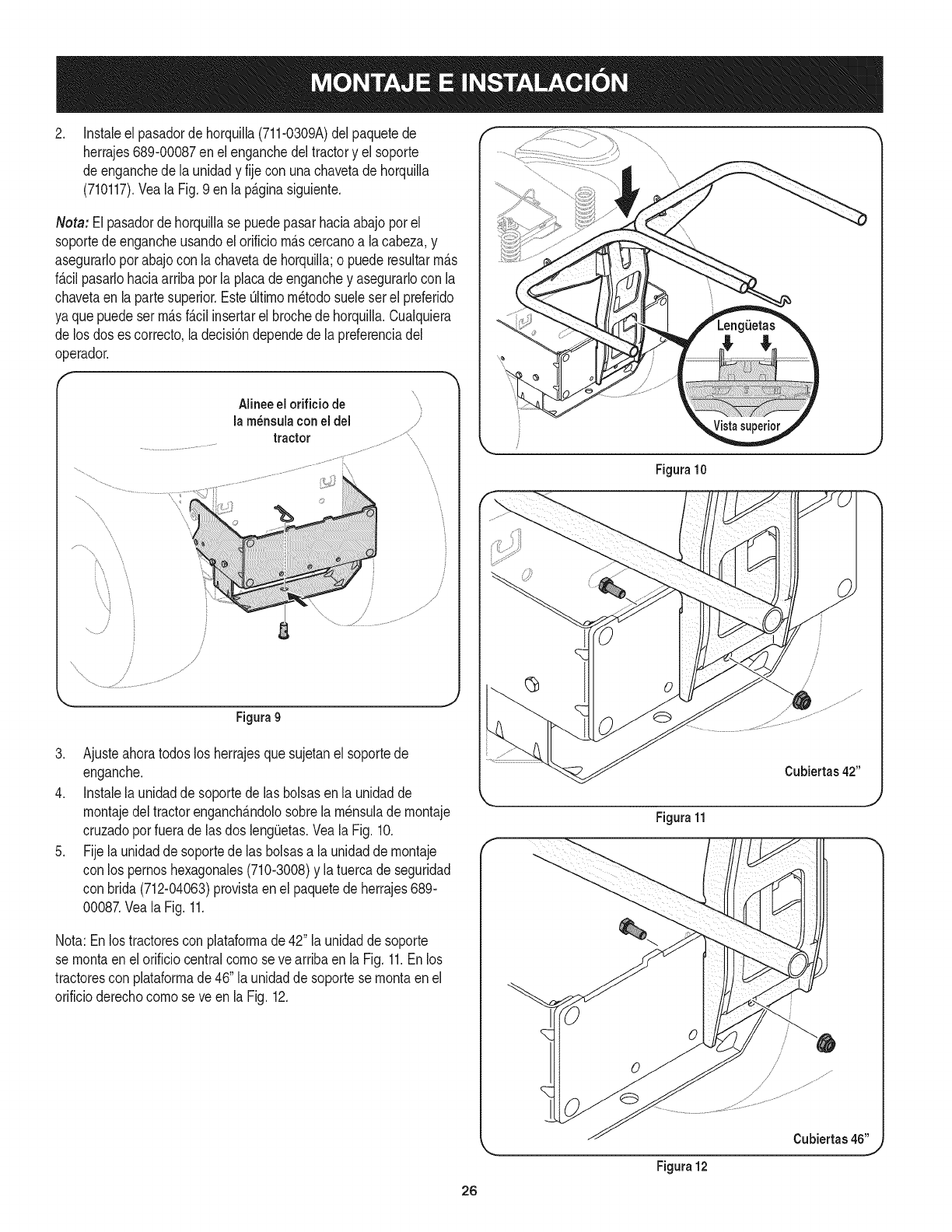
.Instaleel pasadorde horquilla(711-0309A)delpaquetede
herrajes689-00087enel enganchedeltractory el soporte
de enganchede la unidady fije con unachavetadehorquilla
(710117).Veala Fig.9 enla p_.ginasiguiente.
Neta: El pasadordehorquillase puedepasarhaciaabajopot el
soportede engancheusandoel orificiom_.scercanoa lacabeza,y
asegurarloporabajocon la chavetade horquilla;o puederesultarm_.s
f_.cilpasarlohaciaarribaporla placade enganchey asegurarlocon la
chavetaen la parte superior.EsteOltimom_todosueleser el preferido
ya quepuedeserm_.sf_.cilinsertarel brochede horquilla.Cualquiera
de los doses correcto,ladecisi6ndependedela preferenciadel
operador.
j
..............J
4
Alineeel orificiode
lam_nsulaconeldel
tractor ...............
iiiiiilliiiiii!iiiiiii! !' i i' iiiiiiiiiiliiilif!ii
.....i_iiiiii!_ii!i_!ili!iiiiiiiiii!i_iiiiililiiii!iiiiiiiii_iiii_iiii_ii_ii_ii_iiiiiii_iiiiiiii!i!i'_
f
,/
/
/
Figura9
3. Ajusteahoratodoslos herrajesquesujetanel soportede
enganche.
4. Instalela unidadde soportede las bolsasenla unidadde
montajedeltractorenganch_.ndolosobrela m_nsulade montaje
cruzadoporfuerade lasdos leng(Jetas.Veala Fig.10.
5. Fijela unidadde soportede las bolsasa launidadde montaje
con los pernoshexagonales(710-3008)y la tuercade seguridad
con brida(712-04063)provistaenel paquetede herrajes689-
00087.Veala Fig.11.
Nota:Enlostractorescon plataformade42" la unidadde soporte
se montaen elorificiocentralcornoseve arribaenla Fig. 11.Enlos
tractorescon plataformade 46"la unidadde soportese montaenel
orificioderechocomose ve en la Fig.12.
Figura 10
Figura 11
Figura 12
Cubiertas 42"
Cubiertas 46"
26
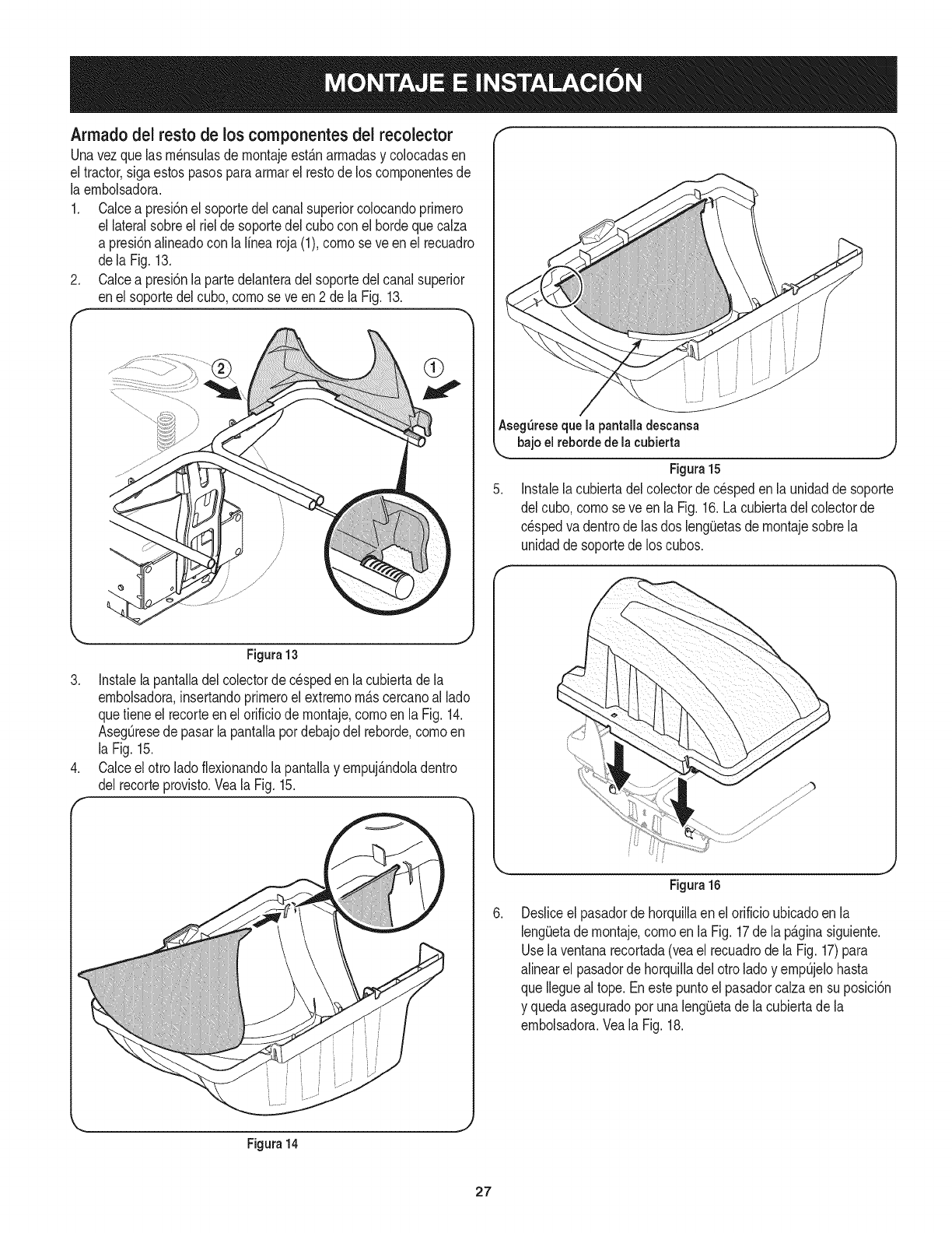
Armadodel resto de los componentes dei recolector
Unavezquelas rn_nsulasdernontajeest_.narmadasy colocadasen
el tractor,sigaestos pasosparaarrnarel restode los cornponentesde
la ernbolsadora.
1. Calcea presi6nel soportedelcanal superiorcolocandoprirnero
el lateralsobreel rielde soportedelcubocon el hordequecalza
a presi6nalineadocon la linearoja(1),cornose ve enel recuadro
dela Fig.13.
2. Calcea presi6nlapartedelanteradel soportedelcanalsuperior
enel soportedelcubo,cornoseve en2 de la Fig.13.
F*"
Figura13
3. Instalelapantalladel colectorde c_spedenla cubiertadela
ernbolsadora,insertandoprirneroel extrernorn_.scercanoal lado
quetieneel recorteenel orificiode rnontaje,cornoen la Fig.14.
AsegOresede pasarla pantallapordebajodel reborde,cornoen
la Fig.15.
4. Calceel otro ladoflexionandola pantallay ernpuj_.ndoladentro
del recorteprovisto.Veala Fig. 15.
f
Aseg_resequelapantalladescansa
bajoel rebordedelacubierta
Figura15
5. Instalela cubiertadelcolectorde c_spedenla unidadde soporte
del cubo,cornoseve en la Fig.16.Lacubiertadel colectorde
cespedva dentrode lasdos leng_Jetasde rnontajesobrela
unidadde soportede loscubos.
Figura14
Figura 16
Desliceel pasadordehorquillaenel orificioubicadoenla
lengiJetade rnontaje,cornoen la Fig.17de la p_.ginasiguiente.
Usela ventanarecortada(veael recuadrode laFig. 17)para
alinearel pasadorde horquilladel otroladoy ernpOjelohasta
que Ileguealtope.Enestepuntoel pasadorcalzaen su posici6n
y quedaaseguradoporunaleng(Jetadela cubiertadela
ernbolsadora.Veala Fig.18.
27
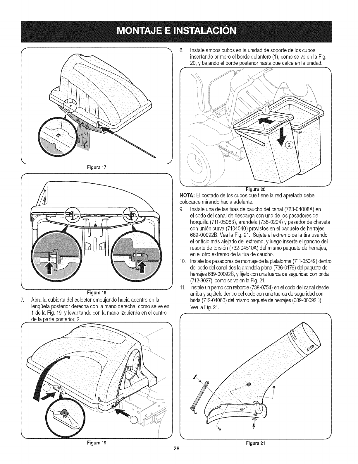
Figura17
Figura18
7. Abrala cubiertadelcolectorempujandohaciaadentroen la
leng0etaposteriorderechacon lamanoderecha,comose ve en
1de la Fig.19,y levantandocon la manoizquierdaenel centro
de lapa[t# poste[b[, 2.
,Instaleamboscubosenla unidadde soportedelos cubos
insertandoprirneroel bordedelantero(1),comose ve enla Fig.
20, y bajandoel hordeposteriorhastaquecalceen la unidad.
Figura20
NOTA:Elcostadodelos cubosquetiene la redapretadadebe
colocarcemirandohaciaadelante.
9. Instaleunade las tirasde cauchodelcanal (723-04008A)en
el codo delcanalde descargacon unodelos pasadoresde
horquilla(711-05063),arandela(736-0204)y pasadordechaveta
con uni6ncurva(7104040)provistosen el paquetede herrajes
689-00092B.Veala Fig.21. Sujeteel extremode latira usando
el orificiom_.salejadodel extrerno,y luegoinserteel ganchodel
resortedetorsi6n(732-04510A)del mismopaquetede herrajes,
en el otroextremode la tirade caucho.
10. Instalelospasadoresdernontajede laplataforma(711-05049)dentro
delcododelcanaldoslaarandelaplana(736-0176)delpaquetede
herrajes689-00092B,y fijeloconunatuercadeseguridadconbrida
(712-3027),cornoseve enlaFig.21.
11. Instaleunpernoconreborde(738-0754)enelcododelcanaldesde
arribay suj6telodentrodelcodoconunatuercadeseguridadcon
brida(712-04063)delmismopaquetedeherrajes(689-00092B).
VealaFig.21.
Figura 19 Figura 21
28
12. f
f
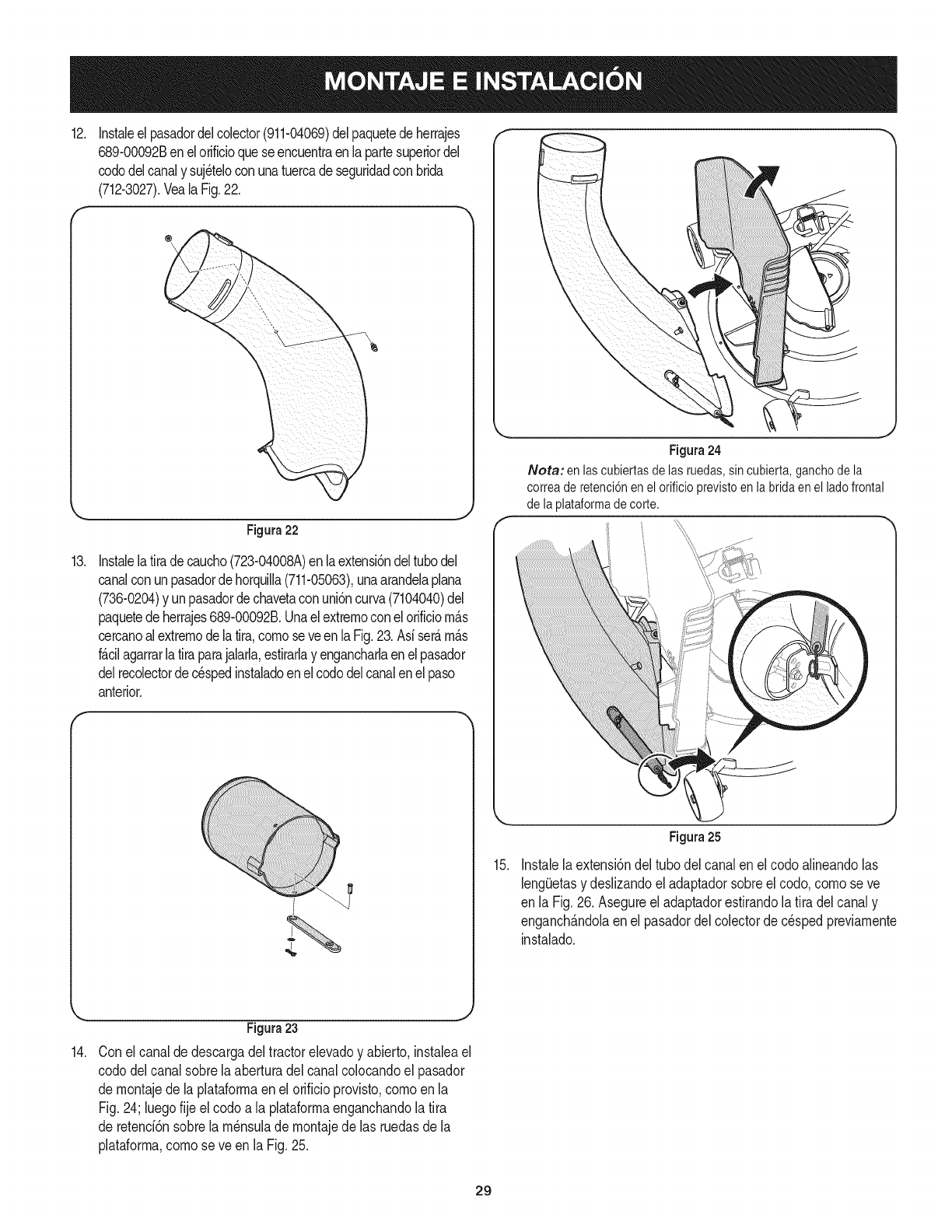
Instaleelpasadordelcolector(911-04069)delpaquetedeherrajes
689-00092Benelorificioqueseencuentraenlapartesuperiordel
cododelcanaly suj_telocon unatuercade seguridadconbrida
(712-3027).VealaFig.22.
®\
,. j
Figura22
13. InstalelaIra decaucho(723-04008A)enlaextensi6ndeltubodel
canalconunpasadordehorqulla(711-05063),unaarandelaplana
(736-0204)y unpasadordechavetaconuni6ncurva(7104040)del
paquetedeherrajes689-00092B.Unaelextrernoconel orilciom_.s
cercanoalextremodelaIra, comose veenlaFig.23.Asiser£m_.s
f_.cilagarrarlaIra parajalarla,estirarlay engancharlaenelpasador
delrecolectordec_spedinstaladoenelcododelcanalenel paso
anterior.
Figura24
Nora: enlascubiertasdelasruedas,sincubierta,ganchodela
correaderetenci6nenelorificioprevistoenlabridaenel ladofrontal
delaplataformadecorte.
15.
Figura25
Instalela extensi6ndel tubodelcanalen el codoafneandolas
lengietasy deslzandoeladaptadorsobreelcodo,comose ve
en la Fig.26. Asegureel adaptadorestirandolatira delcanaly
enganch_.ndolaen el pasadordel colectorde cespedpreviamente
instalado.
14.
Figura23
Conel canalde descargadeltractorelevadoy abierto,instaleael
cododelcanal sobrelaaberturadelcanalcolocandoel pasador
de rnontajede laplataforrnaenel orificioprovisto,cornoenla
Fig.24; luegofije el codoa la plataformaenganchandola Ira
de retend6nsobrela m_nsulade montajede las ruedasde la
plataforma,comose ve enla Fig.25.
29
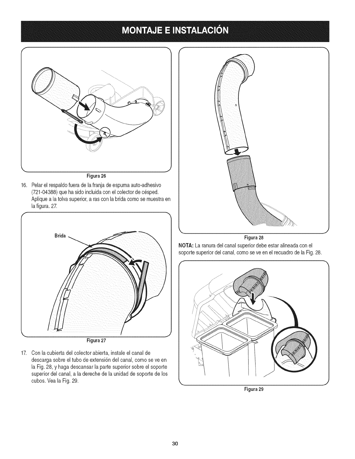
Figura26
16. Pelarel respaldofuerade lafranjadeespumaauto-adhesivo
(721-04388)que hasidoincluidaconel colectorde c_sped.
Apliquea latolvasuperior,a ras conla bridacornose rnuestraen
lafigura.27.
Brida
/
Figura27
Figura28
NOTA: La ranuradelcanal superiordebeestaralineadaconel
soportesuperiordelcanal,cornose veen el recuadrodela Fig.28.
17. Con lacubierta delcolectorabierta, instaleel canalde
descargasobre el tubo deextensi6ndel canal,cornose ve en
la Fig.28, y hagadescansarla parte superiorsobreel soporte
superiordel canal,a la derechede la unidadde soportede los
cubos.Veala Fig.29.
Figura 29
3O
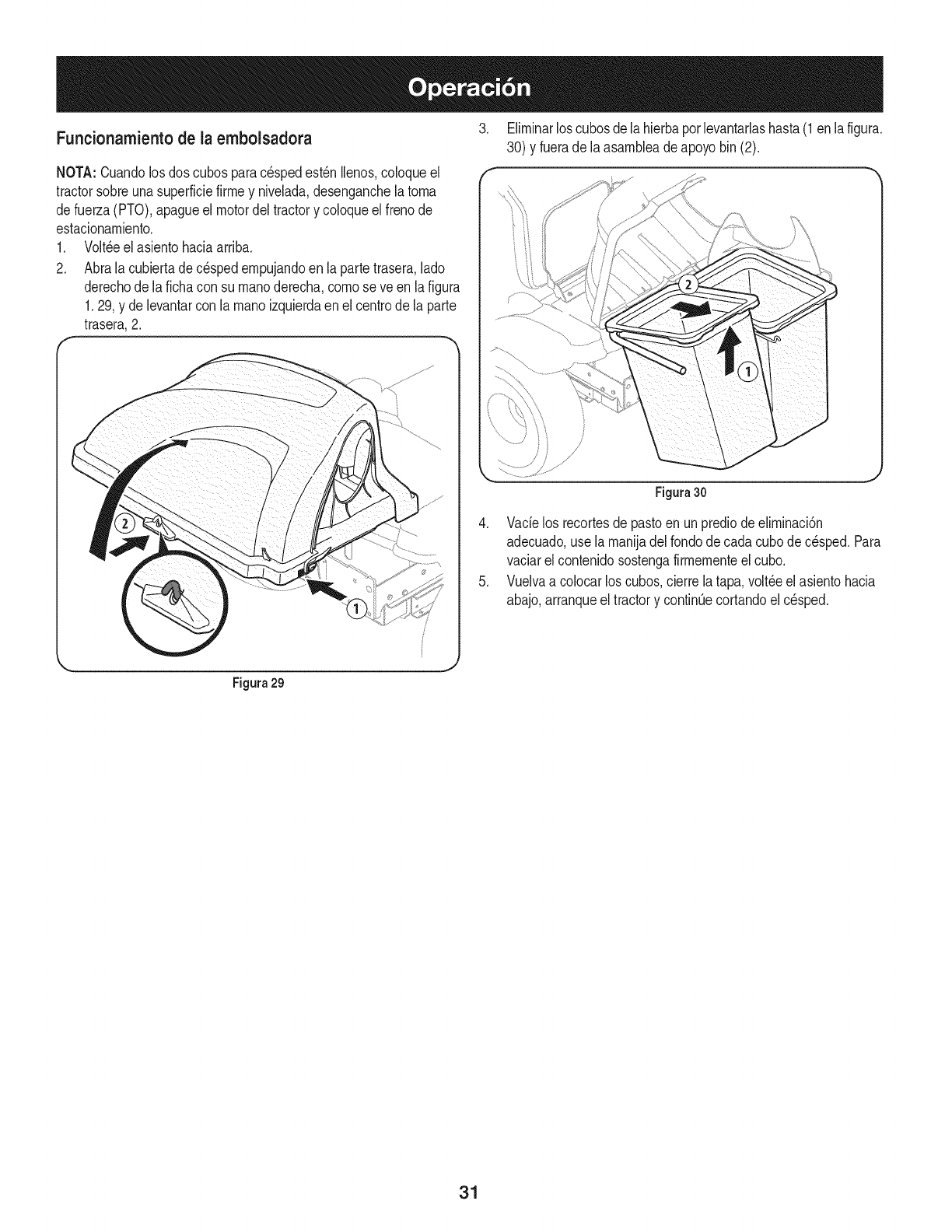
Funcionamientode la embolsadora
NOTA:Cuandolosdos cubosparacespedest_nIlenos,coloqueel
tractorsobreunasuperficiefirrney nivelada,desenganchela torna
defuerza(PTO),apagueel motordeltractory coloqueelfrenode
estacionarniento.
1. Volt,eel asientohaciaarriba.
2. Abralacubiertade cespedernpujandoen laparte trasera,lado
derechode lafichacon su rnanoderecha,cornose veen la figura
1.29, y de levantarcon la rnanoizquierdaen elcentrode la parte
trasera,2.
3. Elirninarloscubosde lahierbaporlevantarlashasta(1en lafigura.
30) y fuerade laasarnbleadeapoyobin(2).
Figura30
4. Vacielos recortesde pastoen unprediode elirninaci6n
adecuado,use larnanijadelrondode cadacubode c_sped.Para
vaciarel contenidosostengafirrnernenteelcubo.
5. Vuelvaa colocarloscubos,cierrela tapa,volt_eel asientohacia
abajo,arranqueel tractory continOecortandoel c_sped.
Figura 29
31

Your Home
For troubleshooting, product manuals and expert advice:
managernylife
www.managemylife.com
For repair - in your home - of all major brand appliances,
lawn and garden equipment, or heating and cooling systems,
no matter who made it, no matter who sold it!
For the replacement parts, accessories and
owner's manuals that you need to do-it-yourself.
For Sears professional installation of home appliances
and items like garage door openers and water heaters.
1-800-4-MY-HOME ®(1-800-469-4663)
Call anytime, day or night (U.S.A. and Canada)
www.sears.com www.sears.ca
Our Home
For repair of carry-in items like vacuums, lawn equipment,
and electronics, call anytime for the location of your nearest
Sears Parts & Repair Service Center
1-800-488-1222 (U.S.A.) 1-800-469-4663 (Canada)
www.sears.com www.sears.ca
To purchase a protection agreement on a product serviced by Sears:
1-800-827-6655 (U.S.A.) 1-800-361-6665 (Canada)
Para pedir servicio de reparaci6n
a domicilio, y para ordenar piezas:
1-888-SU-HOGAR ®
(1-888-784-6427)
www.sears.com
Au Canada pour service en frangais:
1-800-LE-FOYER Mc
(1-800-533-6937)
www.sears.ca
® Registered Trademark /TMTrademark of KCD IP, LLC in the United States, or Sears Brands, LLC in other countries
® Marca Registrada !TMMarca de Fabrica de KCD IP, LLC en Estados Unidos, o Sears Brands, LLC in otros paises
MCMarque de commerce !MDMarque deposee de Sears Brands, LLC
