MTD 21AB455C730 User Manual REAR TINE TILLER Manuals And Guides 1108683L
User Manual: MTD 21AB455C730 21AB455C730 MTD REAR TINE TILLER - Manuals and Guides View the owners manual for your MTD REAR TINE TILLER #21AB455C730. Home:Lawn & Garden Parts:MTD Parts:MTD REAR TINE TILLER Manual
Open the PDF directly: View PDF ![]() .
.
Page Count: 24
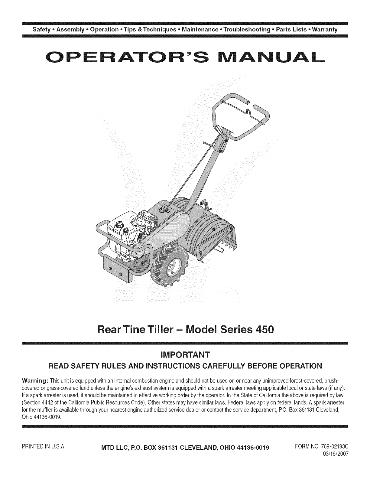
Safety • Assembly • Operation • Tips & Techniques • Maintenance • Troubleshooting • Parts Lists • Warranty
OF AOAL
Rear Tine Tiller - Model Series 450
iMPORTANT
READ SAFETY RULES AND iNSTRUCTiONS CAREFULLY BEFORE OPERATION
Warning: Thisunit is equippedwithan internalcombustionengineandshouldnot beusedon or nearany unimprovedforest-covered,brush-
coveredor grass-coveredlandunlesstheengine'sexhaustsystemisequippedwitha sparkarrestermeetingapplicablelocalor statelaws(if any).
If a sparkarresteris used,it shouldbemaintainedineffectiveworkingorderby the operator.In theStateof Californiathe aboveis requiredbylaw
(Section4442of the CaliforniaPublicResourcesCode).Otherstatesmayhavesimilarlaws.Federallawsapplyonfederallands.A sparkarrester
for the muffleris availablethroughyour nearestengineauthorizedservicedealeror contactthe servicedepartment,RO.Box361131Cleveland,
Ohio44136-0019.
PRINTEDIN U.S.A MTD LLC, P.O. BOX 361131 CLEVELAND, OHIO 44136-0019 FORMNO.769-02193C
03/16/2007
This Operator's Manual is an important part of your new tiller, it will help you assemble,
prepare, and maintain the unit for best performance. Please read and understand what it says.
Table of
Safety Labels ...................................................... 3
Safe Operation Practices ................................... 4
Assembling Your Tiller ........................................ 6
Know Your Tiller .................................................. 8
Operating Your Tiller ......................................... 10
Making Adjustments ........................................ 11
Contents
Maintaining Your Tiller ...................................... 12
Off Season Storage .......................................... 13
Parts List ........................................................... 14
Troubleshooting ................................................ 20
Notes .................................................................. 21
Warranty ............................................. Back Cover
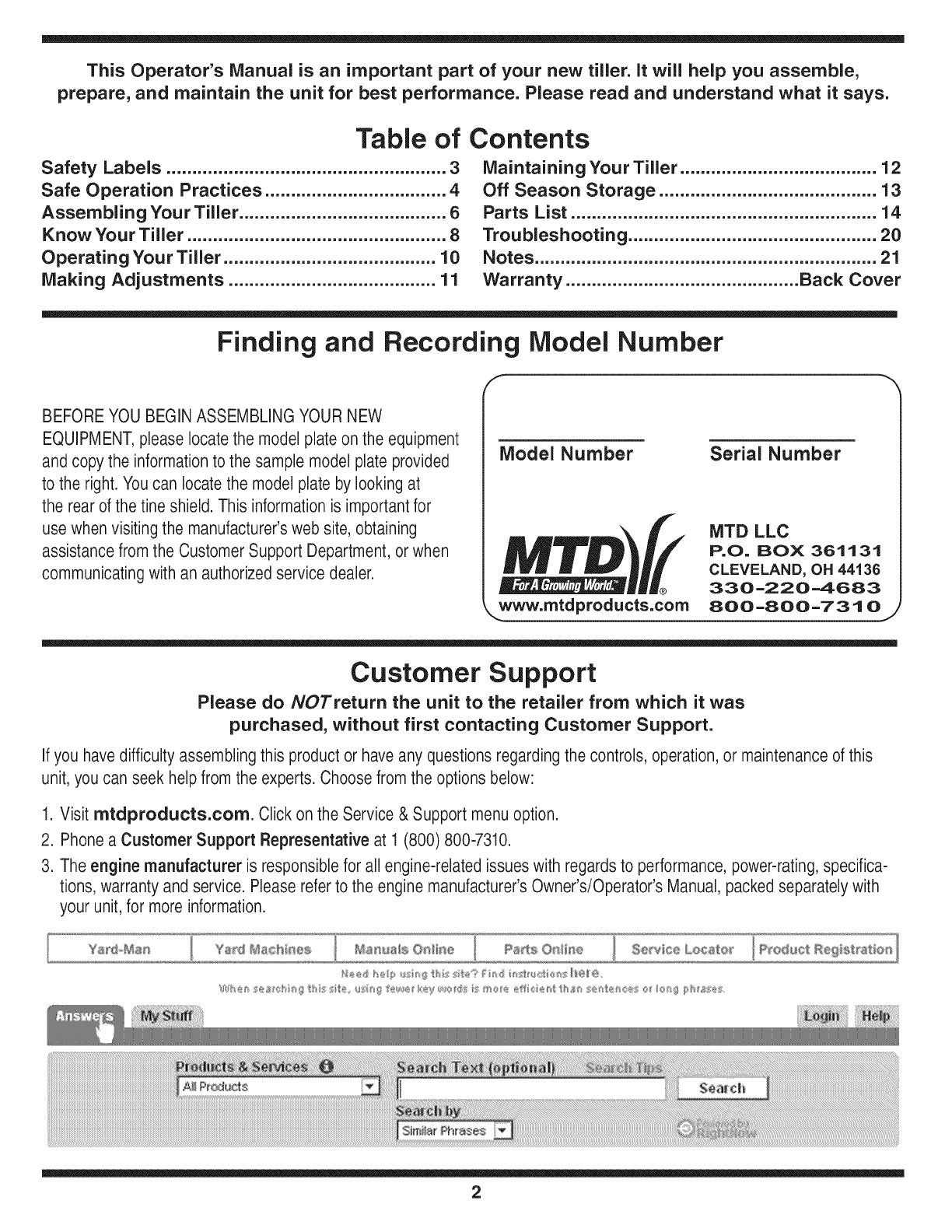
Finding and Recording Model Number
BEFOREYOU BEGIN ASSEMBLINGYOUR NEW
EQUIPMENT,pleaselocatethe model plate on the equipment
and copy the informationto the sample model plate provided
to the right. You can locatethe model plate by looking at
the rearof the tine shield. This informationis importantfor
use when visiting the manufacturer'sweb site, obtaining
assistance from the Customer Support Department, or when
communicatingwith an authorizedservice dealer.
Model Number
www.mtdproducts.com
Serial Number
MTD LLC
P.O= BOX 361131
CLEVELAND, OH 44136
330=220=4683
800-800-731 0
Customer Support
Please do NOTreturn the unit to the retailer from which it was
purchased, without first contacting Customer Support.
Ifyou have difficulty assembling this product or have any questions regardingthe controls, operation,or maintenanceof this
unit, you can seek help from the experts.Choose from the options below:
1. Visit mtdproducts.com. Click on the Service & Support menu option.
2. Phonea Customer Support Representative at 1 (800) 800-7310.
3. The engine manufacturer is responsiblefor all engine-relatedissues with regardsto performance, power-rating,specifica-
tions, warranty and service. Pleasereferto the engine manufacturer'sOwner's/Operator's Manual, packed separatelywith
your unit, for more information.
2
3
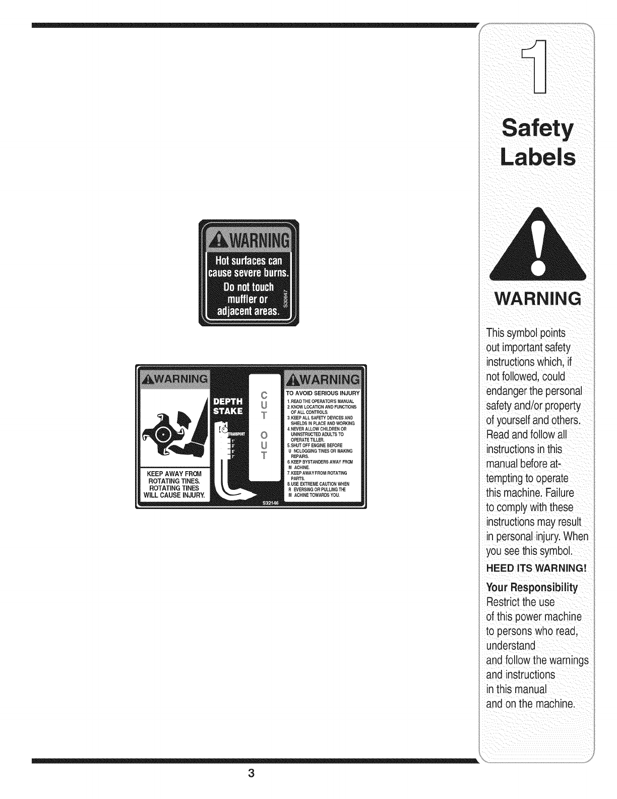
WARNING
This symbolpoints
out importantsafety
instructionswhich, if
not followed,could
endangerthe personal
safetyand/or property
of yourselfandothers.
Readandfollow all
instructionsinthis
manualbeforeat-
temptingto operate
this machine.Failure
to complywiththese
instructionsmay result
in personalinjury.When
you see this symbol.
HEED ITS WARNING!
Your Responsibility
Restrictthe use
of this power machine
to persons who read,
understand
and follow the warnings
and instructions
in this manual
and onthe machine.
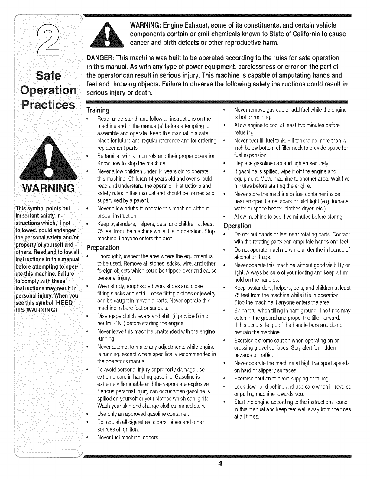
WARNING
Thissyrnbolpointsout
importantsafety in-
structionswhich, ff not
followed,could endanger
ithe personalsafetyand/or
i property of yourself and
others_Readand follow all
Iinstructionsinthisrnanual
i beforeattempting tooper-
iatethis machine.Failure
fITS WARNING!
WARNING: Engine Exhaust, some of its constituents, and certain vehicle
components contain or emit chemicals known to State of California to cause
cancer and birth defects or other reproductive harm.
DANGER: This machine was built to be operated according to the rules for safe operation
in this manual. As with any type of power equipment, carelessness or error on the part of
the operator can result in serious injury.This machine is capable of amputating hands and
feet and throwing objects. Failure to observe the following safety instructionscould result in
serious injury or death.
Training
•Read,understand,andfollowall instructionson the
machineandin the manual(s)beforeattemptingto
assemNeand operate.Keepthis manualin a safe
placefor futureandregularreferenceandfor ordering
replacementparts.
•Befamiliarwithallcontrolsandtheirproperoperation.
Knowhowto stopthe machine.
•Neverallowchildrenunder14yearsoldto operate
thismachine.Children14yearsoldandover should
readand understandthe operationinstructionsand
safetyrulesin thismanualand shouldbe trainedand
supervisedbya parent.
•Neverallowadultsto operatethismachinewithout
properinstruction.
• Keepbystanders,helpers,pets,andchildrenat least
75feetfromthe machinewhileit is in operation.Stop
machineif anyoneentersthe area.
Preparation
•Thoroughlyinspectthe areawherethe equipmentis
to beused.Removeall stones,sticks,wire,andother
foreignobjectswhichcould betrippedoverandcause
personalinjury.
•Wearsturdy,rough-soledworkshoesandclose
fittingslacksand shirt.Loosefittingclothesor jewelry
canbe caughtin movaNeparts. Neveroperatethis
machinein barefeetorsandals.
•Disengagedutch leversandshift (if provided)into
neutral("N') beforestartingthe engine.
•Neverleavethis machineunattendedwiththe engine
running.
•Neverattemptto makeanyadjustmentswhileengine
is running,exceptwherespedficallyrecommendedin
theoperator'smanual.
•Toavoidpersonalinjuryor propertydamageuse
extremecarein handlinggasoline.Gasolineis
extremelyflammableandthe vaporsareexplosive.
Seriouspersonalinjurycan occurwhengasolineis
spilledon yourselfor yourclotheswhichcan ignite.
Washyourskinandchangeclothesimmediately.
•Useonlyanapprovedgasolinecontainer.
• Extinguishall cigarettes,cigars, pipesand other
sourcesof ignition.
•Neverremovegas cap oraddfuel whilethe engine
ishot or running.
•Allowengineto coolat leasttwominutesbefore
refueling
•Neveroverfill fuel tank.Fill tankto nomorethanY2
inch belowbottomof filler neckto providespacefor
fuelexpansion.
•Replacegasolinecapandtightensecurely.
•If gasolineis spilled,wipe it off theengineand
equipment.Movemachineto anotherarea.Waitfive
minutesbeforestartingthe engine.
•Neverstorethe machineorfuel containerinside
nearanopenflame,sparkor pilotlight(e.g.furnace,
wateror spaceheater,clothesdryer,etc.).
•Allowmachineto cool fiveminutesbeforestoring.
Operation
•Do not puthandsor feetnearrotatingparts.Contact
withthe rotatingpartscan amputatehandsandfeet.
•Do notoperatemachinewhileunderthe influenceof
alcoholor drugs.
•Neveroperatethismachinewithoutgoodvisibilityor
light.Nwaysbesureof yourfootingandkeepa firm
holdonthe handles.
•Keepbystanders,helpers,pets,andchildrenat least
75feetfromthe machinewhileit is in operation.
Stopthe machineif anyoneentersthe area.
•Becarefulwhentilling inhardground.The tinesmay
catchin thegroundand propelthe tillerforward.
If thisoccurs,let godthe handlebarsanddo not
restrainthe machine.
•Exerciseextremecautionwhenoperatingonor
crossinggravelsurfaces.Stayalert for hidden
hazardsortraffic.
•Neveroperatethe machineat hightransportspeeds
onhardor slipperysurfaces.
•Exercisecautionto avoidslippingor falling.
•Lookdownandbehindanduse carewhenin reverse
orpullingmachinetowardsyou.
•Starttheengineaccordingto the instructionsfound
in thismanualandkeepfeetwell awayfromthe tines
at alltimes.
• Neverfuelmachineindoors.
4
• Afterstrikingaforeignobject,stopthe engine,
disconnectthe sparkplugwireandgroundagainst
the engineThoroughlyinspectthe machinefor any
damage.Repairthe damagebeforestartingand
operating.
• Disengageall clutchlevers(if fitted)and stopengine
beforeyouleavethe operatingposition(behindthe
handles).Waituntilthe tinescometo a complete
stopbeforeuncloggingthe tines,makingany adjust-
ments,or inspections.
• Neverrunanengineindoorsorin a poorlyventilated
area. Engineexhaustcontainscarbonmonoxide,an
odorlessanddeadlygas.
• Mufflerandenginebecomehot andcancausea
burn. Donot touch.
• Usecautionwhentilling nearfences,buildingsand
undergroundutilities.Rotatingtinescan cause
propertydamageor personalinjury.
• Donot overloadmachinecapacityby attemptingto
till soiltoo deepat too fastof a rate.
• Ifthe machineshouldstart makinganunusualnoise
or vibration,stoptheengine,disconnectthe spark
plugwireand groundit againstthe engine.Inspect
thoroughlyfor damage.Repairanydamagebefore
startingandoperating.
• Keepallshields,guards,andsafetydevicesin place
andoperatingproperly.
• Neverpick uporcarrymachinewhilethe engineis
running.
Useonly attachmentsandaccessoriesapproved
by the manufacturer.Failureto do so can resultin
personalinjury.
• Ifsituationsoccurwhichare notcoveredin this
manual,usecare andgoodjudgment.Contactyour
dealerorcall the customerservicenumberfoundon
pagetwo.
Maintenance & Storage
• Nevertamperwithsafetydevices.Checktheir
properoperationregularly.
• Checkboltsand screwsfor propertightnessat
frequentintervalsto keepthe machinein safe
workingcondition.Also,visuallyinspectmachine
for anydamage.
• Beforecleaning,repairing,or inspecting,stopthe
engineandmakecertainthetinesandall moving
partshavestopped.Disconnectthe sparkplug
wireandgroundit againstthe engineto prevent
unintendedstarting.
• Do notchangethe enginegovernorsettingsor
over-speedthe engine.Thegovernorcontrolsthe
maximumsafeoperatingspeedof the engine.
• Maintainor replacesafetyandinstructionlabels,
as necessary.
• Followthismanualfor safeloading,unloading,
transporting,and storageof this machine.
• Neverstorethe machineorfuel containerinside
wherethere is anopenflame,sparkor pilotlight
suchasa waterheater,furnace,clothesdryer,etc.
• Alwaysreferto the operator'smanualfor proper
instructionson off-seasonstorage.
• If thefuel tankhas to bedrained,do thisoutdoors.
• Observeproperdisposallawsand regulationsfor
gas,oil,etc. to protecttheenvironment.
Your Responsibility
• Restrictthe use of thispowermachineto persons
who read,understand,andfollowthe warningsand
instructionsin thismanualand onthe machine.
• The safetylabelsonthe tillerare showninthe
"SafetyLabels"section.Toensuresafeoperation
of the tiller,followthe instructionsonall labels
closely.
5
Practices
WARNING
Thissymbolpointsout
importantsafety in-
structions which,if not
followed, couldendanger
the personalsafetyand/or
propertyof yourself and
others.Readandfollow all
instructionsinthis manual
before attempting to oper-
ate this machine. Failure
to comply with these
instructions may result in
personal injury. Whenyou
see this symbol, HEEDITS
WARNING!
WARNING
Disconnectthe spark
plug wire and ground
it against the engine
to prevent unintended
starting.
Be certain to check
the clutchcable
adjustment before
operatingthe tiller.
NOTE:specificationsare
subjecttochangewithout
notification or obligation
imagesmynot reflect your
exact modelandarefor
refeiencepurposeson!y
NOTE: Referencesto rightorleft sideof thetillerare ff
determinedfrombehindthe unitintheoperatingposition.
To Remove Unit From Carton
•Removestaples,breakglueon topflaps,or cuttape
at cartonend andpeelalongtop flapto opencarton.
•Removeloosepartsincludedwithunit (i.e.,
operator'smanual,etc.).
•Cutcornersandlay cartondownflat.
•Removepackingmaterial.
•Rollor slideunit out of carton.Checkcarton
thoroughlyfor looseparts.
•Extendcontrolcableand layonthe floor.Becareful
not to bendor kinkcontrolcable.
IMPORTANT:Thisunit isshippedwithoutgasoline
oroil intheengine.Becertainto serviceenginewith
gasolineandoil as instructedinthe separateengine
manualbeforeoperatingyourmachine.
Loose Parts In Carton
•DepthStake
•HandleAssembly
•ShiftRod
NOTE: Allhardwareneededforassemblyisattached
to the loosepartsorthe tiller.
Before Assembly
_ ARNING: Disconnectthe spark plug
wire and ground it against the engineto
preventunintended starting.
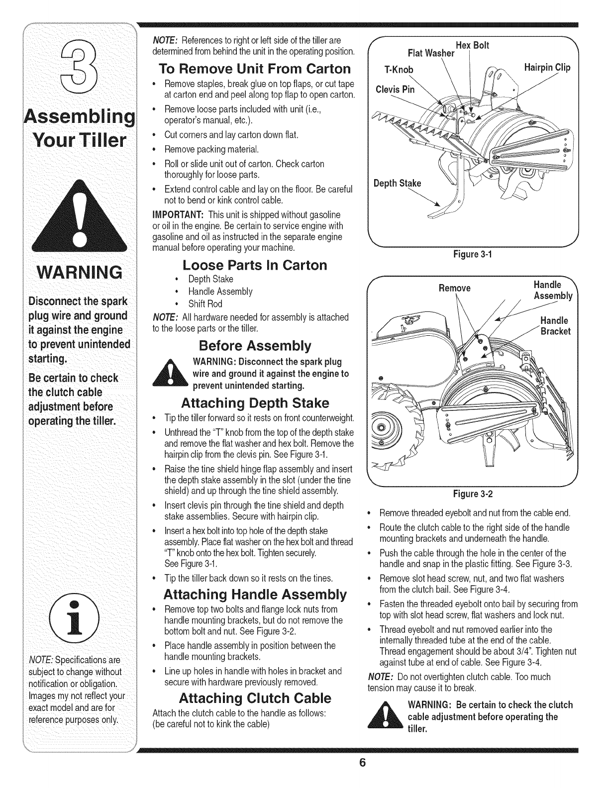
Attaching Depth Stake
•Tipthe tillerforwardsoit restsonfrontcounterweight.
•Unthreadthe"T"knobfromthe topof thedepthstake
andremovethe flatwasherandhexbolt.Removethe
hairpinclipfromtheclevispin.SeeFigure3-1.
•Raisethe fine shieldhingeflap assemblyandinsert
the depthstakeassemblyintheslot (underthe tine
shield)andupthroughthefine shieldassembly.
•Insertclevispinthroughthefine shieldanddepth
stakeassemblies.Securewithhairpinclip.
•Inserta hexboltintotopholeofthedepthstake
assembly.Placeflatwasheronthehexboltandthread
"T"knobontothehexbolt.Tightensecurely.
SeeFigure3-1.
•Tip thetiller backdownso it restson thetines.
Attaching Handle Assembly
•Removetoptwo boltsandflange locknutsfrom
handlemountingbrackets,but donot removethe
bottomboltandnut.See Figure3-2.
•Placehandleassemblyinpositionbetweenthe
handlemountingbrackets.
•Lineupholesin handlewithholesin bracketand
securewithhardwarepreviouslyremoved.
Attaching Clutch Cable
Attachtheclutchcable to the handleas follows:
(becarefulnot to kinkthe cable)
HexBolt
FlatWasher
T-Knob
o Hairpin Clip
DepthStake
f
Figure 3-1
Remove
J
Handle
Assembly
Handle
Figure 3-2
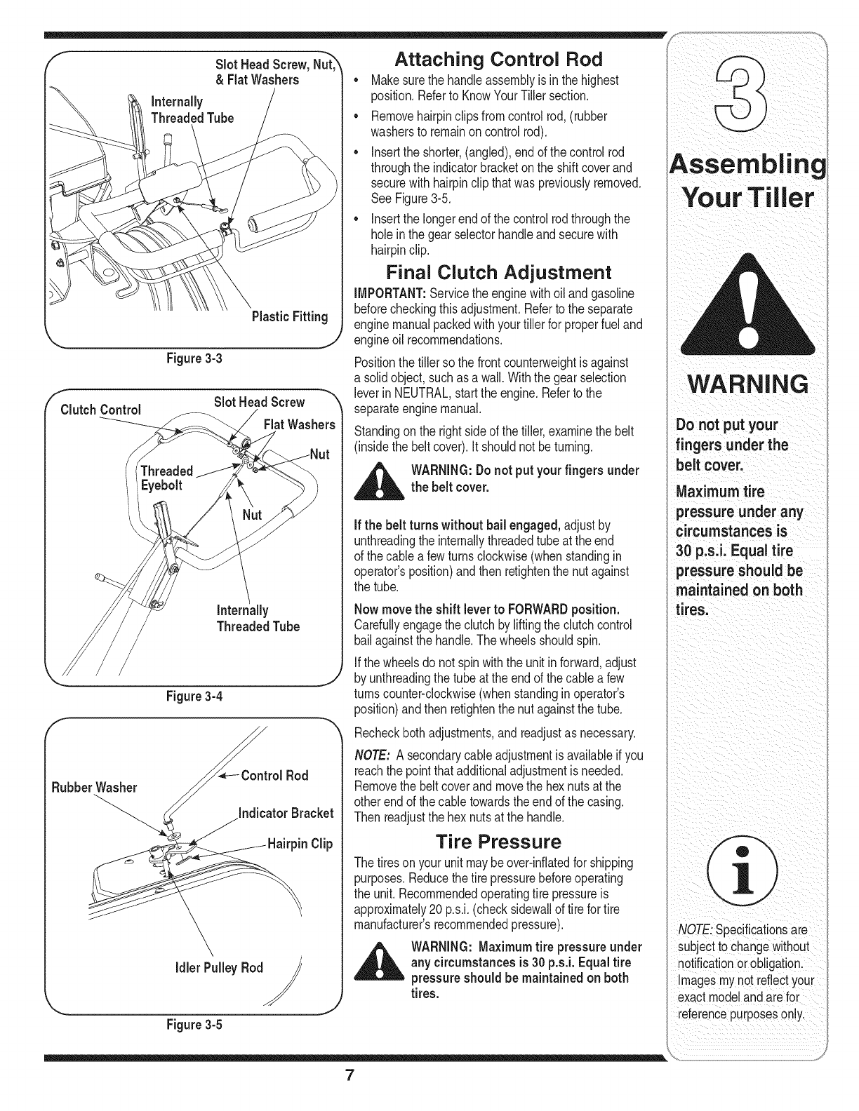
•Removethreadedeyeboltandnutfromthecableend.
•Routethe clutchcableto the right sideof the handle
mountingbracketsand underneaththe handle.
•Pushthecable throughthe holeinthecenterof the
handleandsnapin the plasticfitting.See Figure3-3.
•Removeslotheadscrew,nut,andtwoflatwashers
fromtheclutch bail.SeeFigure3-4.
•Fastenthe threadedeyeboltontobailby securingfrom
top withslotheadscrew,flatwashersandlock nut.
•Threadeyeboltandnut removedearlierinto the
internallythreadedtubeat theendof the cable.
Threadengagementshouldbeabout3/4".Tightennut
againsttubeat endof cable.SeeFigure3-4.
NOTE: Do notovertightenclutchcable.Toomuch
tensionmaycauseit to break.
_ ARNING: Becertain to checkthe clutch
cable adjustment before operating the
tiller.
6
B
fSlotHeadScrew,Nut_,
& FiatWashers
PlasticFitting
\ t
Figure 3-3
f
ClutchControl SlotHeadScrew
FiatWashers
ut
J
Figure 3-4
//
RubberWasher /Control Rod
idlerPulleyRod
\ J
Figure 3-5
Attaching Control Rod
•Makesurethe handleassemblyisinthe highest
position.Referto KnowYourTiller section.
• Removehairpinclipsfromcontrolrod,(rubber
washersto remainon controlrod).
• Insertthe shorter,(angled),endof the controlrod
throughthe indicatorbracketonthe shift coverand
securewithhairpinclip thatwaspreviouslyremoved.
SeeFigure3-5.
• Insertthe longerendof the controlrodthroughthe
holeinthe gearselectorhandleand securewith
hairpinclip.
Final Clutch Adjustment
IMPORTANT:Servicethe enginewithoilandgasoline
beforecheckingthis adjustment.Referto the separate
enginemanualpackedwithyourtiller for properfueland
engineoil recommendations.
Positionthe tiller so the frontcounterweightis against
a solidobject,suchas awall.Withthe gearselection
leverinNEUTRAL,startthe engine.Referto the
separateenginemanual.
Standingonthe right sideof the tiller,examinethe belt
(insidethe beltcover).It shouldnot beturning.
_ARNING:Donotputyourfingers under
the belt cover.
If the belt turns without bail engaged,adjustby
unthreadingthe internallythreadedtubeat the end
of the cablea fewturnsclockwise(whenstandingin
operator'sposition)and thenretightenthe nut against
the tube.
Now movethe shift lever to FORWARDposition.
Carefullyengagethe clutchby liftingthe clutchcontrol
bailagainstthe handle.Thewheelsshouldspin.
If thewheelsdo not spinwiththe unit inforward,adjust
by unthreadingthe tube at the endof thecable a few
turnscounter-clockwise(whenstandinginoperator's
position)andthen retightenthe nut againstthe tube.
Recheckbothadjustments,and readjustas necessary.
NOTE: A secondarycableadjustmentis availableif you
reachthe pointthatadditionaladjustmentisneeded.
Removethe beltcoverand movethe hexnutsat the
otherendof the cabletowardsthe endof the casing.
Thenreadjustthehex nutsat the handle.
Tire Pressure
Thetireson yourunit maybeover-inflatedfor shipping
purposes.Reducethe tire pressurebeforeoperating
the unit.Recommendedoperatingtire pressureis
approximately20 p.s.i.(checksidewallof tire fortire
manufacturer'srecommendedpressure).
_ARNING: Maximumtire pressureunder
any circumstancesis 30 p.s.i. Equaltire
pressureshouldbe maintainedon both
tires.
7
Do not put your
fingers underthe
belt cover.
Maximum tire
pressure under any
circumstancesis
30 p.s.i. Equal tire
pressure should be
maintained on both
tires.
NOTE:Specificationsa[e
subjectto changewithout
notificationor obligationl
Images my not reflect your
exact modelandarefor
referencepurposeson!y.
/++_..-- .........,...............................,=
ii LI):i;¸ A"k
/i
iGear SelectionHandle......
KnoWYour
Tiller
!
i
WARNING
Make certain unit is
in NEUTRALwhen
starting the engine.
1
NOTE:Specificationsare
isubjectto changewith0ut
notification or obligation
ImageSmynotreflectyour
exact modelandarefo[
[eference purposeson!y,
Handle Adjustment
Depth Stake
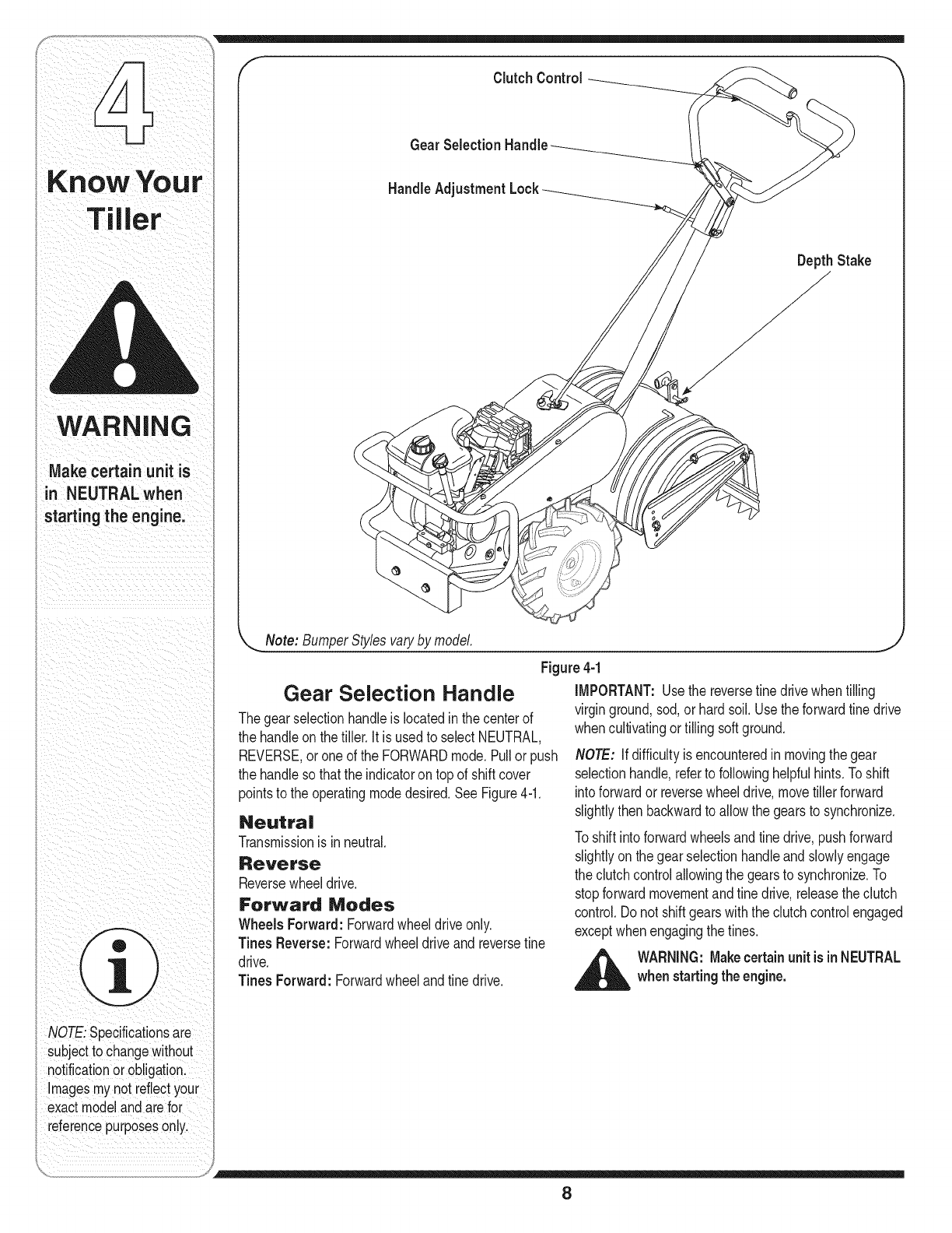
Figure 4-1
Gear Selection Handle
Thegearselectionhandleis locatedinthe centerof
the handleonthe tiller.It is usedto selectNEUTRAL,
REVERSE,oroneof the FORWARDmode.Pullor push
the handleso thatthe indicatoron topof shiftcover
pointsto the operatingmodedesired.SeeFigure4-1.
Neutra|
Transmissionisinneutral.
Reverse
Reversewheeldrive.
Forward Modes
Wheels Forward: Forwardwheeldriveonly.
Tines Reverse: Forwardwheeldriveandreversefine
drive.
Tines Forward: Forwardwheeland tinedrive.
iMPORTANT:Usethe reversefine drivewhentilling
virginground,sod,or hardsoil.Usethe forwardtine drive
whencultivatingortilling softground.
NOTE: If difficultyis encounteredin movingthe gear
selectionhandle,referto followinghelpfulhints.Toshift
intoforwardor reversewheeldrive,movetillerforward
slightlythen backwardto allowthe gearsto synchronize.
Toshift intoforwardwheelsandtine drive,pushforward
slightlyon the gearselectionhandleandslowlyengage
the clutchcontrolallowingthe gearsto synchronize.To
stopforwardmovementandfine drive,releasethe clutch
control.Donot shiftgearswiththe clutchcontrolengaged
exceptwhenengagingthetines.
_ARNING: Makecertainunit is inNEUTRALwhenstarting the engine.
8
Clutch Control
The clutchcontrolis locatedbeneaththe handle.
Squeezingthe clutchcontrolagainstthe handleengages
the wheelandfine drivemechanisms.
NOTE: Neverengageclutchleverwhileshifting.
Handle Adjustment Lock
The handlemaybeadjustedto the heightdesired.
Loosenthe handleheightadjustmentlocka fewturns.
Pivothandleupor downto desiredposition.Tightenlock.
Throttle Control
The throttlecontrolleveris locatedonthe engine.It
controlstheenginespeedand stopstheengine.
Choke Lever flf Equipped)
The chokeleveris locatedby the throttle.It is usedto
enrichthe fuel mixtureinthe carburetorwhen startinga
cold engine.
Primer Button (if Equipped)
The primerbuttonis locatedbehindthe aircleaner.It is
usedto enrichthe fuel mixtureinthe carburetorwhen
startinga coldengine.
Depth Stake
The depthstakecontrolsthe tillingdepth.Referto
"Settingthe Depth"inthe OperatingSection.
Engine Controls
Seethe separateenginemanualfor additionalinforma-
tion andfunctionsof theenginecontrols.
KnowYour
iller
This symbol points
instructionswhich, if
notfo =oWed;could
endangerthe pe[sonal
safetyand/or pioperty
of Yourselfand othersl
Read andfollow all
instructionsin this man-
ual before attempting to
operate this machine:
Failureto complywith
these instructionsmay
result in personal injury
When you see this
symbol;
HEED ITS WARNING!
NOTE:SpecificationSare
Subjectto changewithout
notificationor Ob!igation.
Images mynot reflectyour
exact modeland arefo r
referencepurposeson!y,
9
WARNING
Read, understand,
'and follow all instruc-
tions andwarnings
on the machineand
inthis manualbefore
operating.
Use extreme care
whenhandling
gasoline. Gasoline is
extremely flammable
and the vaporsare
iexplosive. Neverfuel
machine indoorsor
while the engine is
hot or running.
Be sure no one is
standing in front of
i the tiller whilethe
engineis runningor
being started.
Becertainspark
plug wire is discon-
nected and grounded
iagainst the engine
when performing any
adjustments.
_hb ARNING:Read,understand, and follow
all instructionsandwarningson the ma-
chine and in this manual before operating.
Before Starting
Gas And Oil Fill-Up
Servicethe enginewithgasolineandoil as instructedin
the separateenginemanualpackedwithyourtiller.Read
instructionscarefully.
WARNING: Useextremecare when
handlinggasoline. Gasoline is extremely
flammable and the vapors are explosive.
Neverfuel machine indoorsor while the
engine is hot or running.
Starting Engine
NOTE: Whenpushingthe unitwiththe engineoff, you
will heara ratchetingsound(gearnoise)whichis normal.
,_ WARNING: Besureno one isstanding in
front of the tiller while the engineis running
or being started.
• Placegearselectionleverin NEUTRAL.
• PlacethethrottlecontrolleverinFASTpositionor
ifequipped,placethe enginespeedcontrolinthe
STARTposition.
• Movechokeleverto CHOKEpositionor ifequipped,
pushprimertwo(2) orthree (3)times.Waitabouttwo
(2) secondsbetweeneach push.
NOTE:A warmenginemaynotrequirechokingorpriming.
• Standat sideof tiller.Graspthe starterhandleandpull
out slowly,until itpulls slightlyharder.Letroperewind
slowly.
• Pullstarterhandlerapidly.Do notallowhandleto snap
back.Allowitto rewindslowlywhilekeepinga firm
holdonthe starterhandle.
• Repeatpreviousstepsuntilenginestarts.
As enginewarmsup andbeginsto operateevenly,
movechokelevergraduallyto RUNposition.Ifengine
falters,returnto chokeposition,then slowlymoveto
RUNposition.
Referto enginemanualforadditionalengineinforma-
tion.
NOTE: Afterstartingandprior to usingthe tiller forthe
firsttime, becertainto checkthe clutchadjustmentas
describedin"Checkingthe ClutchAdjustment"sectionof •
the AssemblyInstructions.
To Stop Engine
•Movethrottlecontrolto STOPorOFFposition.
• Disconnectsparkplugwireandgroundto prevent
accidentallystartingwhileequipmentis unattended.
NOTE: Afterthefirst ten hoursof operation,recheck
the clutchadjustment.Referto finalclutchadjustmentin
AssemblyInstructions.
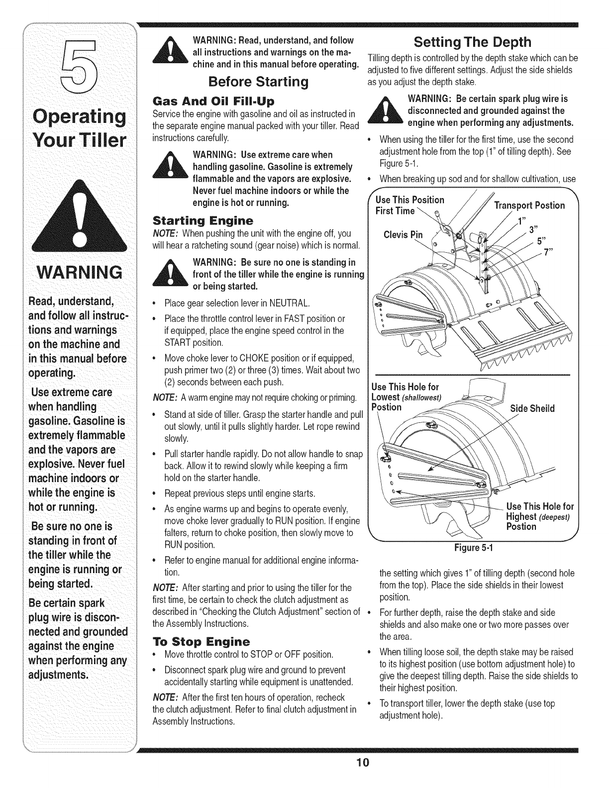
Setting The Depth
Tillingdepthis controlledby the depthstakewhichcan be
adjustedto fivedifferentsettings.Adjustthe side shields
as youadjustthedepth stake.
_ARNING: Becertainspark plug wire is
disconnected and groundedagainst the
engine when performingany adjustments.
• Whenusingthetiller for the firsttime, usethe second
adjustmentholefromthe top (1"of tillingdepth).See
Figure5-1.
• Whenbreakingupsod andfor shallowcultivation,use
Postion
3"
5"
UseThis Hole for
Lowest(shallowest)
Postion Side Sheild
--__Use This Hole for
Highest (deepest)
Postion j
Figure 5-1
the settingwhichgives1"of tillingdepth(secondhole
fromthetop). Placethe side shieldsintheir lowest
position.
Forfurtherdepth,raisethe depthstakeandside
shieldsandalso makeoneortwo morepassesover
the area.
• Whentillingloosesoil,the depthstakemaybe raised
to its highestposition(usebottomadjustmenthole)to
givethe deepesttillingdepth.Raisethe sideshieldsto
theirhighestposition.
• Totransporttiller,lowerthe depthstake(use top
adjustmenthole).
10
Toadjustthedepthstake,removetheclevispinandhairpin
clip.Movethe depthstaketo the desiredsettingand
securewiththe clevispinandhairpinclip.SeeFigure5-1.
Toadjustthe sideshields,removethe wingnuts. Move
the side shieldto thedesiredpositionandreplacethe
wing nuts.Tightensecurely.
Operating the Tiller
•Selectthe depthstakesetting.
•Startengineas instructedonthe previouspage.
•Movegearselectionhandleto oneof the forward
modesor reverse.
WARNING: Donot movethe gearselection
handlewith the wheelsor tines engaged.
Makecertainthe unit is stoppedcom-
pletely before changingthe gearselection.
A partialengagementmay be necessary
when engagingtines.
iMPORTANT:Usethe reversefine drivewhen tilling
virginground,sod,orhardsoil.Usethe forwardfine drive
whencultivatingor tillingsoft ground.
•Squeezethe clutchhandleagainstthe handleto
engagethe wheelsandtines.
NOTE: Makecertainthe gearselectionindicatoris
correctlypositionedbeforeengagingthe clutchhandle.If
it isbetweengears,the enginewill stall.
Totransporttiller,do not engagethe tines. Selectthe
wheeldriveonly.
,_ WARNING: Donot pushdownon the
handlesso that the wheels are lifted off
the groundwhile using the tine drive,or
the tiller couldmovebackward and cause
personalinjury.
Forbestresults,itis recommendedthe gardenbetilled
twice (lengthwise,then width-wise)to pulverizethe soil.
Making Adjustments
,_ WARNING: Neverattempt to makeany
adjustments whilethe engineis running,
exceptwherespecifiedinoperator's
manual.
Handle Adjustment
The handleheightmaybeadjustedto the desiredheight.
Referto the handleadjustmentinKnowYourTiller
section.
Belt Tension Adjustment
Periodicadjustmentof the belttensionmaybe required
dueto normalstretchand wearonthe belt.Adjustment
isneededif the tinesor wheelsseemto hesitatewhile
turning,butthe enginemaintainsthe samespeed.
Toadjustthe tensionon thebelt, referto FinalClutch
AdjustmentinAssemblyInstructions.
Afterbelttensionhas beenadjusted,if the beltis
excessivelystretched,youmayneedto adjustthe idler
pulleyrod.Thiscan easilybechecked.
Withtheengineoffandthe clutchcontrolbaildisen-
gaged,shiftthe gearselectionhandleto eachforward
mode.If the indicatorbrackettouchesthe idlerpulley
rod(withthe clutchcontrolbaildisengaged),thenan
adjustmentis necessary.
• Disconnectandgroundout sparkplugwire against
the engine.
• Removethe beltcoveras describedunderBelt
Replacementin the Maintenancesection.
• Removethe hairpinclip and springwasherfromthe
idlerpulleyrod. Referto Figure9.
• Movethe idlerpulleyrodto the lowerholeinthe idler
bracket.
• Replacethe springwasherandhairpinclip.
• Checkclearanceof the idlerpulleyrodto the
indicatorbracketby shiftingto each forwardmode,
as before.
Engine Adjustment
Referto the separateenginemanualfor engineadjust-
mentinstructions.
NOTE:Specificationsaresubjectto
changewithoutnotificationor obligation.
Imagesmynot reflectyourexactmodel
andarefor referencepurposesonly.
ustm
WARNING
Do not movethe gear
selection handle
with the wheels or
tines engaged. IVlake
certain the unit is
stopped completely
before changingthe
gear selection. A
partial engagement
may be necessary
when engaging tines.
Do not push down
on the handlesso
that the wheels are
lifted off the ground
while usingthe tine
drive, or the tiller
could move backward
and cause personal
injury.
Never attempt to
make any adjust-
ments while the
engine is running,
except where speci-
fied inoperator's
manual.
11
Maintaining
i
WARNING
Disconnectthe spark
plugwireandground
itagainstthe engine
before performing
any repairsor
maintenance.
NOTE:Specificationsare
subjectto Changewithout
notification or obligation
ImageSmynotreflectyour
exact modelandarefor
reference purposeson!y,
_ARNING: Disconnectthe spark plug
wire and groundit against the engine
before performingany repairs.
Engine
Referto the separateenginemanualforengine
maintenanceinstructions.
Maintainengineoil as instructedinthe separate
enginemanualpackedwithyourunit. Readandfollow
instructionscarefully.
Serviceair cleaner everyten hoursundernormal
conditions.Cleaneveryhourunderextremelydusty
conditions.Poorengineperformanceandflooding
usuallyindicatesthatthe aircleanershouldbe serviced.
Toservicethe aircleaner,referto the separateengine
manualpackedwithyourunit.
IMPORTANT:Neverrunyourenginewithoutaircleaner
completelyassembled.
Thespark plug shouldbe cleanedandthe gap
resetevery25hoursof engineoperation.Sparkplug
replacementis recommendedat the start of eachtiller
season;checkenginemanualfor correctplugtypeand
gapspecification.
Clean the engine regularlywitha clothor brush.Keep
the coolingsystem(blowerhousingarea)cleanto
permitproperair circulationwhichis essentialto engine
performanceandlife.Becertainto removeall dirt and
combustibledebrisfrommufflerarea.
Lubrication
Transmission
Thetransmissionis pre-lubricatedandsealedat the
factory.It requiresnocheckingunlessthetransmission
is disassembled.To fill withgrease,laythe right halfof
the transmissionon its side,add22 ouncesof Benalene
920grease,and assemblethe left halfto it.Thisgrease
can beobtainedat yournearestauthorizeddealerby
orderingpartnumber737-0300.
Clutch Handle
Lubricatethe pivotpointonthe clutchhandleandthe
cableat leastoncea seasonwithlightoil. The control
mustoperatefreelyinboth directions.
Pivot Points
Lubricateall pivotpointsandlinkagesat leastonce a
seasonwithlightoil.
Tine Shafts
Removefineassembliesandlubricatethe fine shaftsat
leastoncea season.
Cleaning Tine Area
Cleanthe undersideof the fine shieldaftereachuse.
Thedirt washesoffthe tineseasierif rinsedoff im-
mediatelyinsteadof afterit dries.Alwaystoweldry the
tillerafterwardsand applya lightcoatof oil orsiliconeto
preventrustingorwaterdamage.
IMPORTANT:Neverusea "pressurewasher"to clean
yourtiller.Watercan penetratetightareasof the tillerand
itschain caseandcauseseriousdamageto the unit.
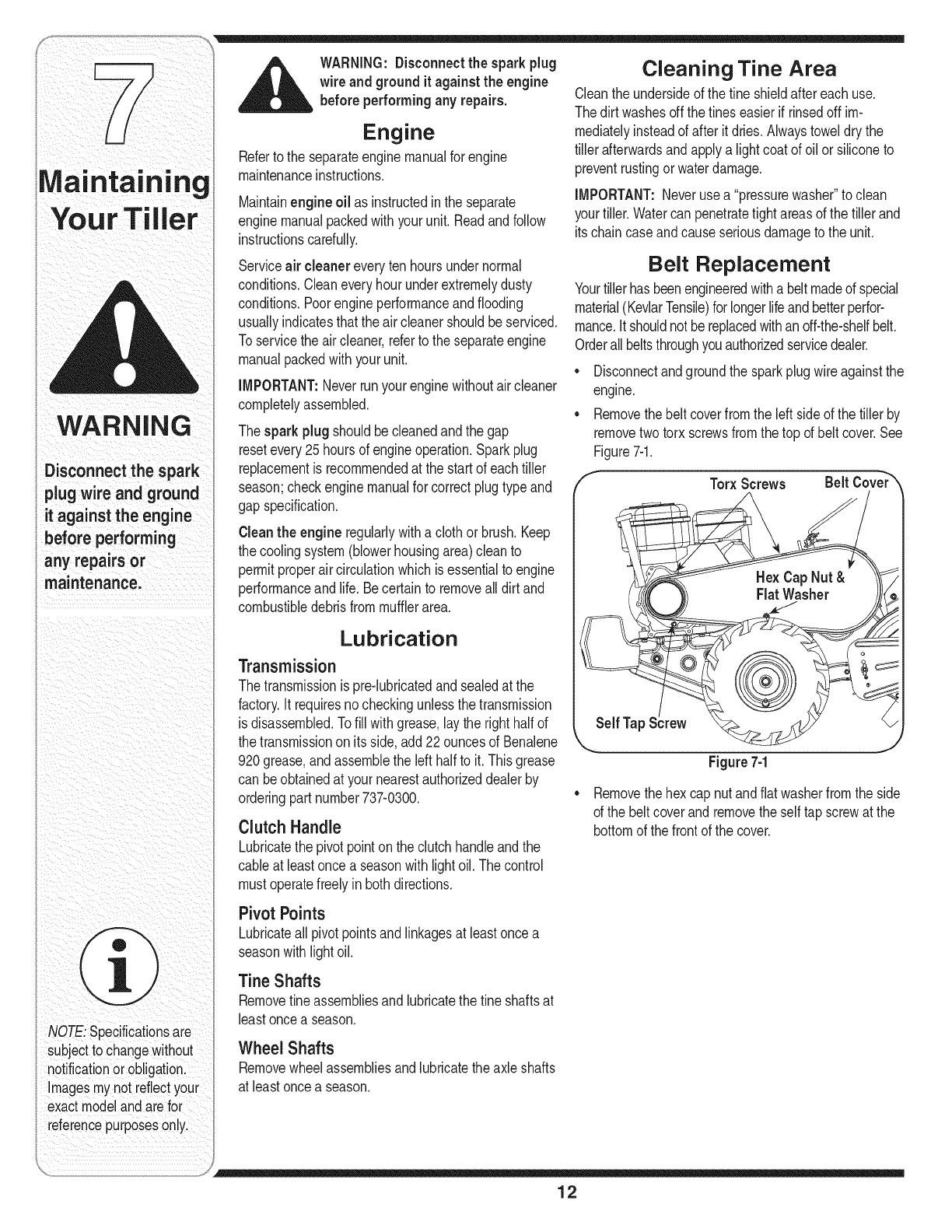
Belt Replacement
Yourtillerhas beenengineeredwitha belt madeof special
material(KevlarTensile)for longerlifeandbetterperfor-
mance.Itshouldnot bereplacedwithanoff-the-shelfbelt.
Orderallbeltsthroughyou authorizedservicedealer.
•Disconnectandgroundthe sparkplugwire againstthe
engine.
• Removethebelt coverfromthe leftside of the tiller by
removetwo torxscrewsfromthe top of belt cover.See
Figure7-1.
Self Tap
Torx Screws
_ FlatWasher
Figure 7-1
Belt Cover_
• Removethehex cap nutandflatwasherfromthe side
of the beltcoverandremovethe selftap screwat the
bottomof thefrontof the cover.
Wheel Shafts
Removewheelassembliesandlubricatethe axleshafts
at leastoncea season.
12
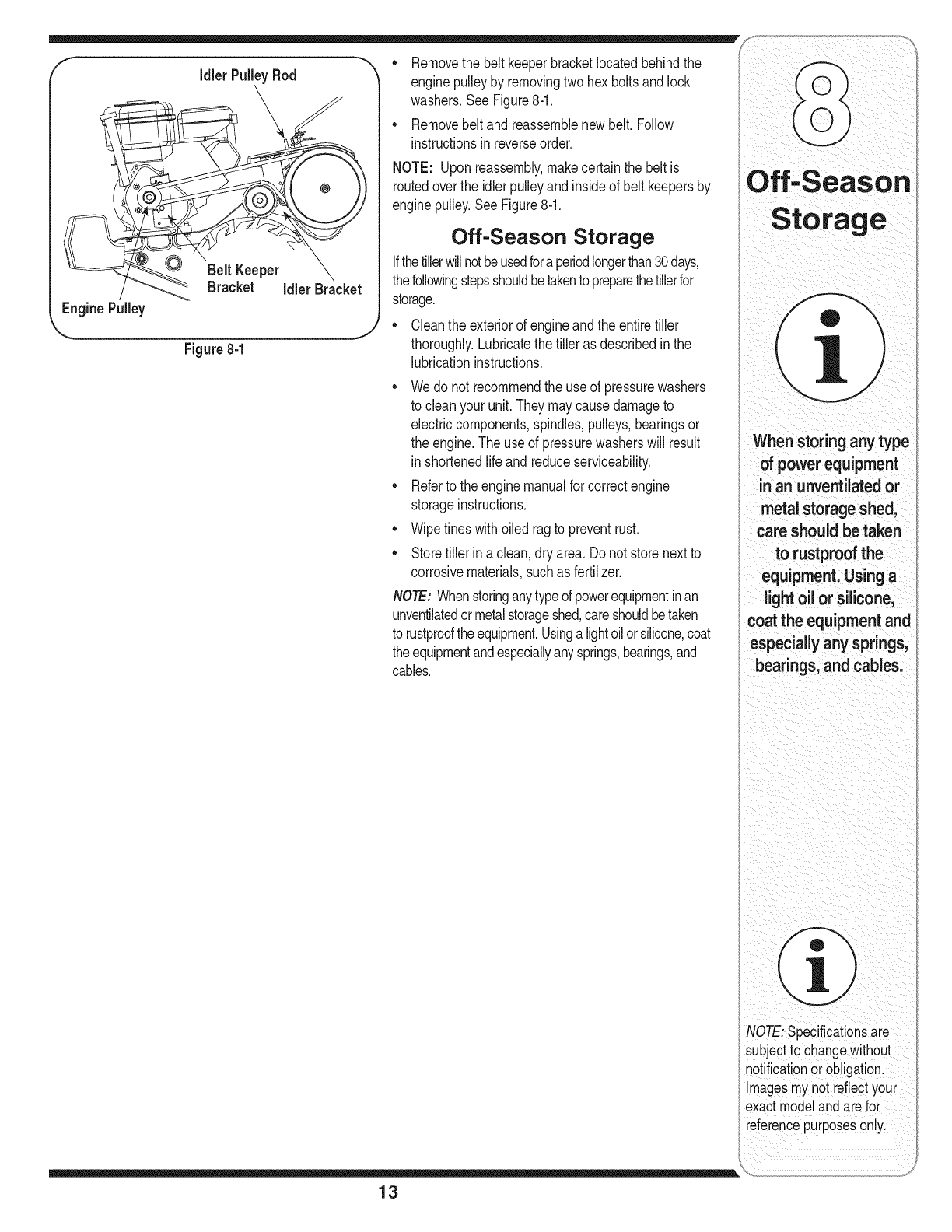
fIdlerPulleyRod
Belt Keeper
Bracket
EnginePulley
Figure 8-1
• Removethe beltkeeperbracketlocatedbehindthe
enginepulleyby removingtwohex boltsandlock
washers.See Figure8-1.
• Removebeltand reassemblenew belt.Follow
instructionsinreverseorder.
NOTE: Uponreassembly,makecertainthe beltis
routedoverthe idlerpulleyandinsideof belt keepersby
enginepulley.SeeFigure8-1.
Off-Season Storage
Ifthetillerwillnotbeusedfora periodlongerthan30days,
thefollowingstepsshouldbetakentopreparethetillerfor
storage.
• Cleantheexteriorof engineand theentiretiller
thoroughly.Lubricatethe tilleras describedinthe
lubricationinstructions.
• Wedo not recommendthe use of pressurewashers
to cleanyourunit.Theymaycausedamageto
electriccomponents,spindles,pulleys,bearingsor
the engine.The useof pressurewasherswill result
in shortenedlifeand reduceserviceability.
• Referto the enginemanualforcorrectengine
storageinstructions.
• Wipetineswithoiledragto preventrust.
Storetillerin a clean,dry area. Donot storenextto
corrosivematerials,suchas fertilizer.
NOTE-Whenstoringanytypeof powerequipmentinan
unventilatedormetalstorageshed,careshouldbetaken
to rustprooftheequipment.Usingalightoilorsilicone,coat
theequipmentandespeciallyanysprings,bearings,and
cables.
13
When storingany type
of powerequipment
in an unventilatedor
metal storage shed,
care should be taken
to rustproof the
equipment. Using a
light oil or silicone,
-oat the equipment and
especially any springs,
bearings, and cables.
NOTE: specificationsare
subject to changewithout
notificationorobligation.
Images mynot reflectyour
exact modelandarefor
referencepurposeson!y,
13
29 53 35
16
46
/
28
18
17
I
I
I
I
23
7.
I
36
15
43
17
45 36
14
i i iiii _ i
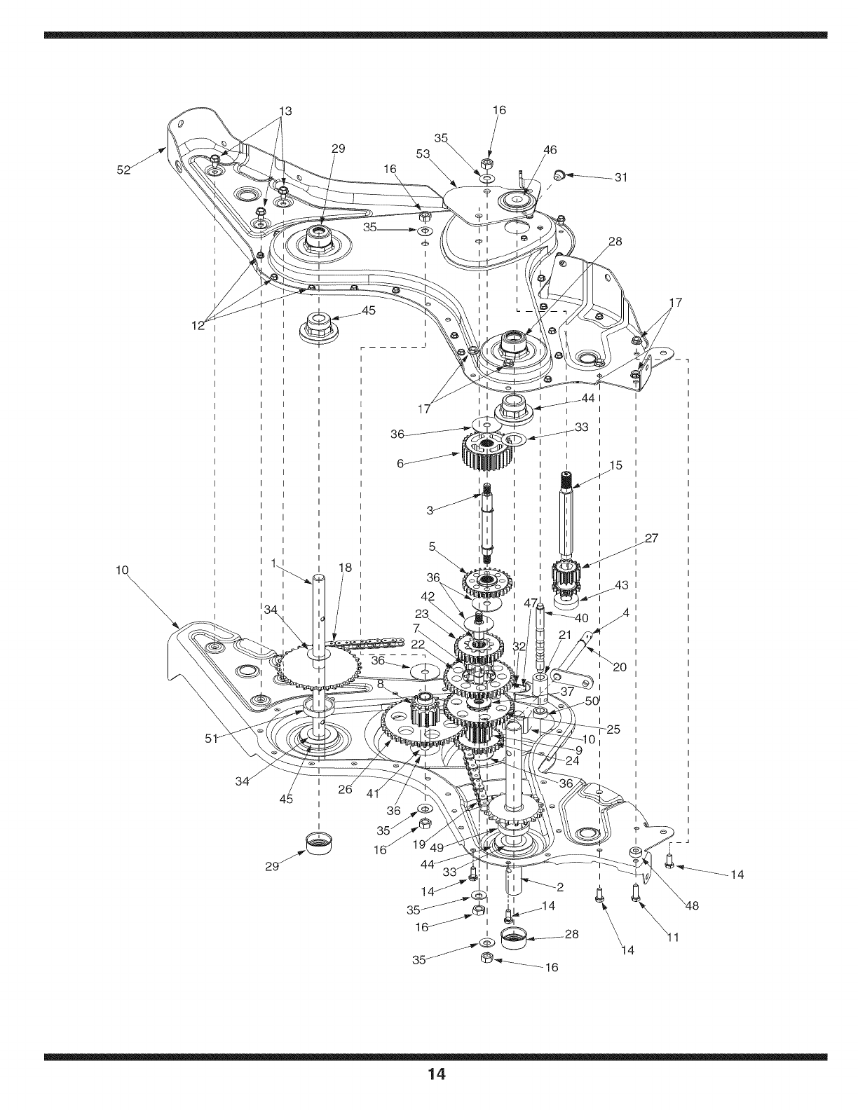
611-04074 WheelShaftAss'y33T 717-1594
2. 611-0021 TineShaftAss'y:18T 28. 721-0378
3. 611-0128 JackShaftAss'y 29. 721-0379
4. 611-0129 inputShaftAss'y 31. 726-0277
5. 617-0058 Rev.IdlerGearAss'y:30T 32. 732-0496
6. 617-0059 TineIdlerGearAss'y:30T 33. 736-0163
7. 617-0060 Tineinput SprocketAss'y:9T 34. 736-0351
8. 617-0061 WheelinputSprocketAss'y:10T 35. 736-0407
9. 617-0062 GearAss'y:11T 36. 736-0518
10. 686-0108 R.H.HousingAss'y 37. 736-3088
11. 710-0376 HexBolt5/16-18x 1"Lg. 40. 738-0645
12. 710-0599 HexS-TapScr.1/4-20x.5" 41. 738-0648
13. 710-0604A HexS-TapScr.5/16-18x.625" 42. 738-1013
14. 710-3008 HexBolt5/16-18x.75" 43. 741-0124
15. 711-1349 inputShaft 44. 741-0420
16. 712-0378 HexNut7/16-20
17. 712-3004A FlangeNut5/16-18 46. 741-0563
18. 713-0367 #420Chain 1/2Pitchx50 Links 47. 741-0862
19. 713-0484 #50Chain5/8 Pitchx 54 Links 48. 750-0258
20. 716-0865 SnapRing 49. 750-0570
21. 717-0853 ShiftingFork 50. 750-0664
22. 717-1582 SpurGear44T 51. 750-0671
23. 717-1583 SpurGear30T 52. 786-0171
24. 717-1584 SpurGear30T 53. 786-0238
25. 717-1585 SpurGear44T
26. 717-1587 SpurGear44T
SpurGear16T
Seal1.0Shaft
Seal.75Shaft
TaperCap Ring
CompressionSpring.50"Leg.
ThrustWash.1.03"I.D.X. 1.62"
FI-Wash.76"I.D.x 1.5"O.D.
Bell-Wash.45"I.D.x 1.0"
ThrustWash..445x 1.92x .060
FI-Wash..635"I.D.x 1.59O.D.
DetentShaft1/2"Dia.
JackShaft.625x 2.385
JackShaft.625x 5.0
BallBearing
FlangeBearing1.0x 2.5x 1.38
45. L741-0421 _Flange Bearing.75x 2.5x 1.38
BallBearing.6692x 5745x .466
DetentBall.250
Spacer.315
Spacer1.0I.Dx 2.00.D. x .440
Spacer.505 I.D.x .88 O.D.x .440
Spacer.75 x 2.0x .50
L.H.ChainCaseAss'y
GearPositionerBracket
686-0107 GearCaseAssemblyComplete
Parts List
Model 450
Series
_FACTORY PARTS
To order replacement
parts, contact
1(800) 800-7310
or visit
www.mtdproducts.com
15
67 12
62
2_ X 37
11
34
27
4O
39
51
26
36
J
33
53
55
24
28
16
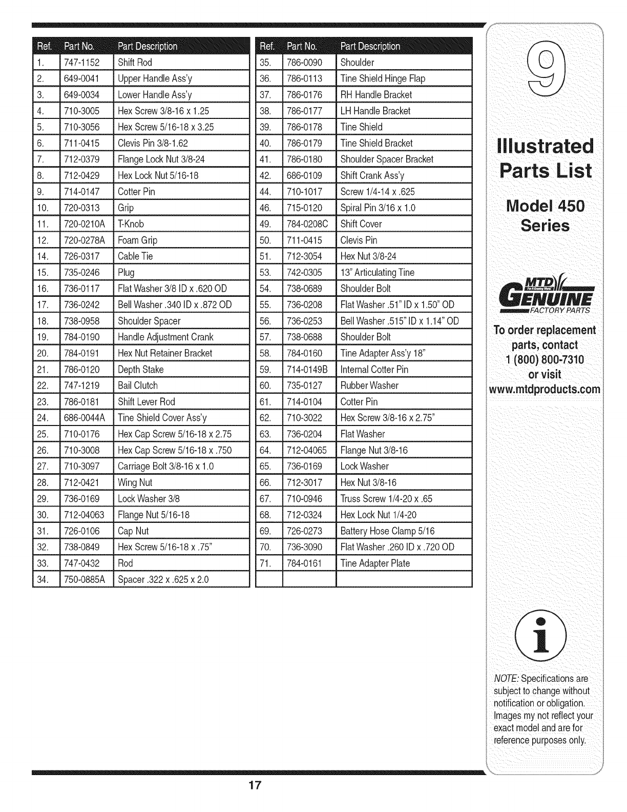
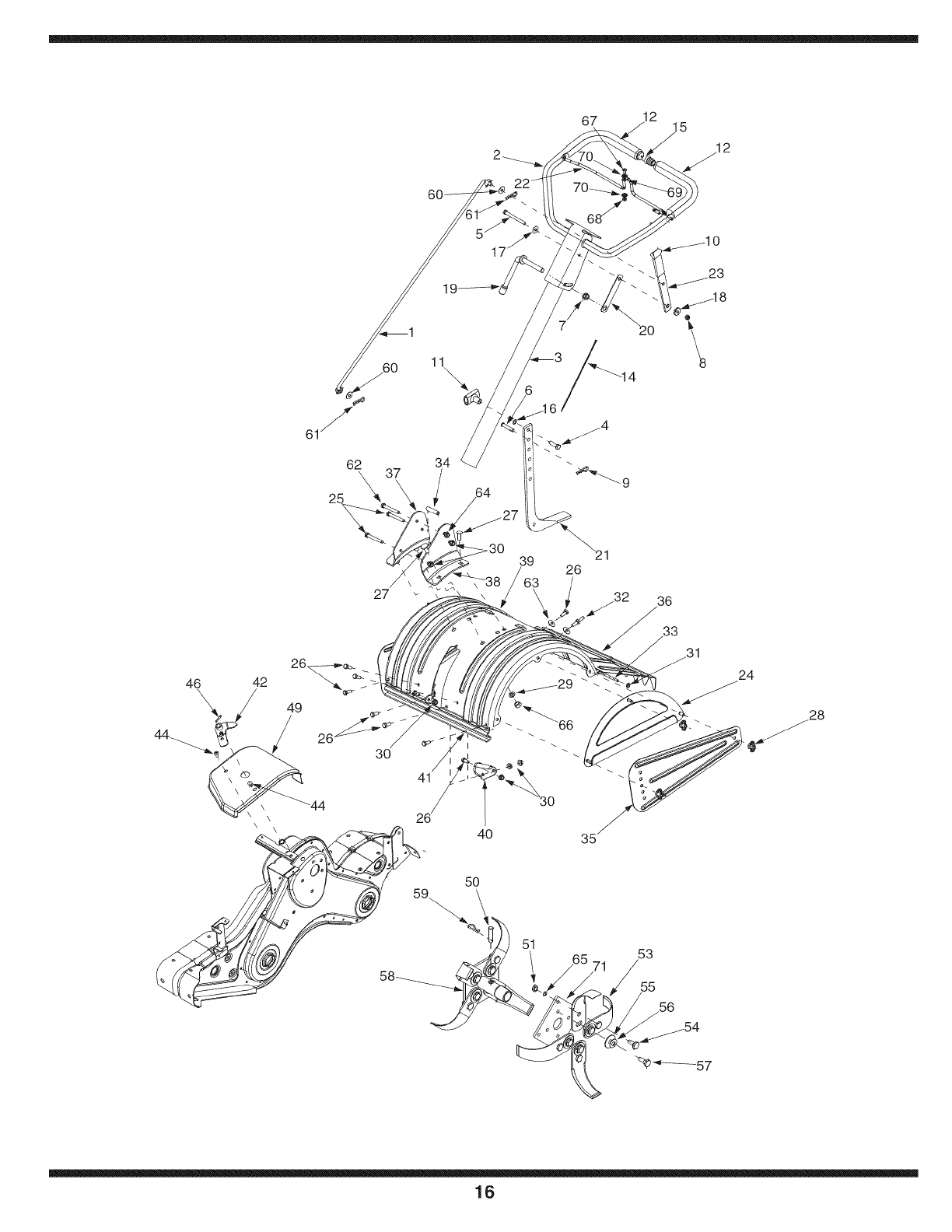
747-1152 ShiftRod
2. 649-0041 UpperHandleAss'y
3. 649-0034 LowerHandleAss'y
4. 710-3005 HexScrew3/8-16x 1.25
5. 710-3056 HexScrew5/16-18x 3.25
6. 711-0415 ClevisPin3/8-1.62
7. 712-0379 FlangeLockNut3/8-24
8. 712-0429 HexLockNut5/16-18
9. 714-0147 CotterPin
10. 720-0313 Grip
11. 720-0210A T-Knob
12. 720-0278A FoamGrip
14. 726-0317 CableTie
15. 735-0246 Plug
16. 736-0117 FiatWasher3/8 IDx .620OD
786-0090 Shoulder d
36. 786-0113 TineShieldHingeFlap i
37. 786-0176 RHHandleBracket
38. 786-0177 LH HandleBracket
39. 786-0178 TineShield
40. 786-0179 TineShieldBracket
41. 786-0180 ShoulderSpacerBracket
42. 686-0109 ShiftCrankAss'y
44. 710-1017 Screw1/4-14x .625
•46. L715-0120 SpiralPin3/16x 1.0
17. 736-0242 BellWasher.340IDx .872OD
18. 738-0958 ShoulderSpacer
19. 784-0190 HandleAdjustmentCrank
20. 784-0191 HexNutRetainerBracket
21. 786-0120 DepthStake
22. 747-1219 BailClutch
23. 786-0181 ShiftLeverRod
49. 784-0208C ShiftCover
50. 711-0415 ClevisPin
51. 712-3054 HexNut3/8-24
53. 742-0305 13"ArticulatingTine
54. 738-0689 ShoulderBolt
55. 736-0208 FiatWasher.51"IDx 1.50"OD
56. 736-0253 BellWasher.515"IDx 1.14"OD
57. 738-0688 ShoulderBolt
58. 784-0160 TineAdapterAss'y18"
59. 714-0149B internalCotterPin
60. 735-0127 RubberWasher
61. 714-0104 CotterPin
illustrated
Parts List
Model 450
Series
_FACTORY PARTS
To order replacement
parts, contact
1(800) 800-7310
or visit
www.mtdproducts.com
24. 686-0044A Tine ShieldCoverAss'y
25. 710-0176 HexCap Screw5/16-18x 2.75
26. 710-3008 HexCap Screw5/16-18x .750
27. 710-3097 CarriageBolt3/8-16x 1.0
28. 712-0421 Wing Nut
29. 736-0169 LockWasher3/8
62. 710-3022 HexScrew3/8-16x 2.75"
63. 736-0204 FiatWasher
64. 712-04065 FlangeNut3/8-16
65. 736-0169 LockWasher
66. 712-3017 HexNut3/8-16
67. 710-0946 TrussScrew1/4-20x .65
30. 712-04063 FlangeNut5/16-18
31. 726-0106 CapNut
32. 738-0849 HexScrew5/16-18x .75"
68. 712-0324
69. 726-0273
70. 736-3090
HexLockNut1/4-20
BatteryHoseClamp5/16
FlatWasher.260IDx .720OD
33. 747-0432 Rod
34. 750-0885A Spacer.322x.625x2.0
71. 784-0161 TineAdapterPlate
NOTE: specificationsare
subjectto changewithout
notificationor obligationl
images mYnot reflectyour
exact modelandarefor
reference purposeson!y,
17
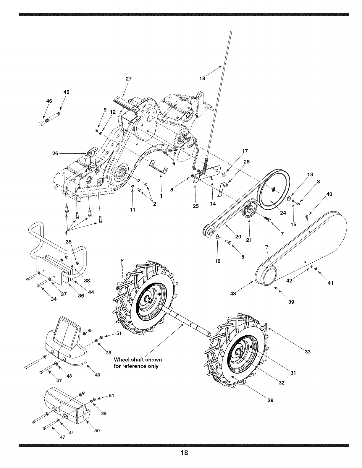
45
26
4
35
37
34
38
I
\0
11
8
18
25 14
17
28
\20 21
5
16
43
42
\39
13
\41
48
47
\49
Wheel shaft shown
for reference only
29
32
33
31
37 50
47
18
i i iiii _ i
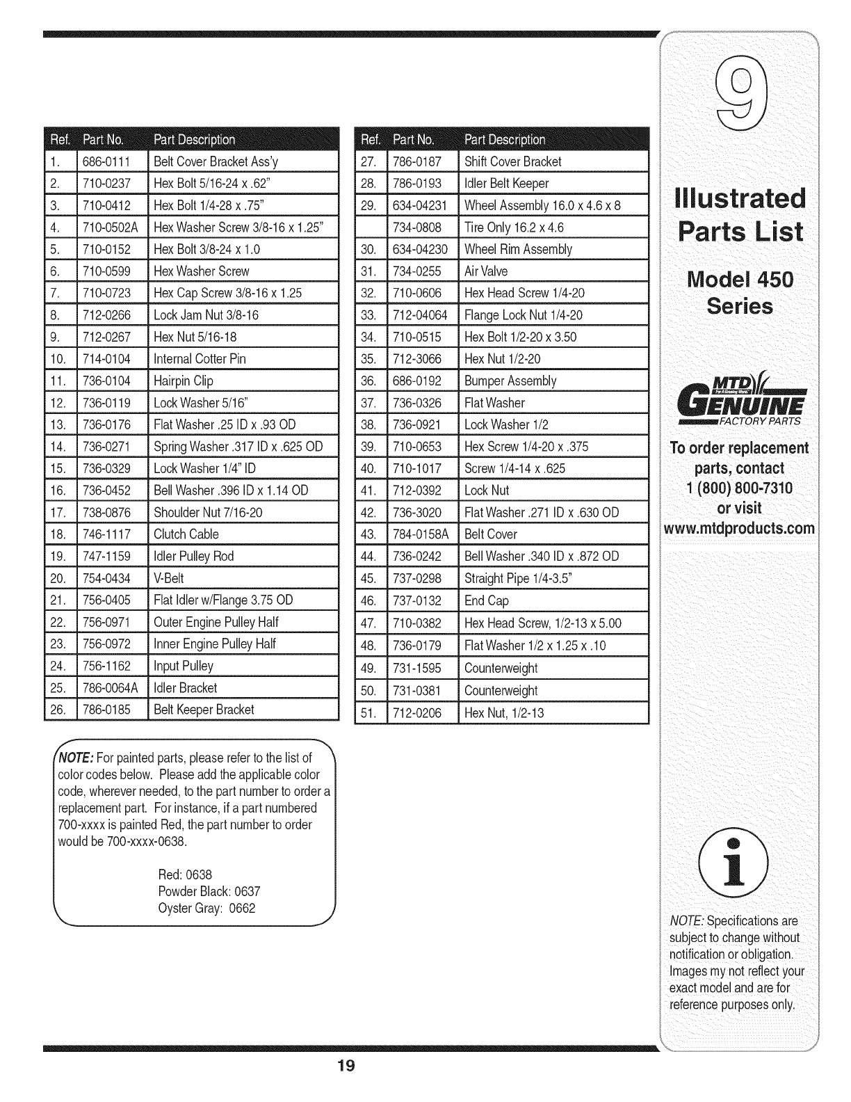
686-0111 BeltCoverBracketAss'y
2. 710-0237 HexBolt5/16-24x .62" •28.
3. 710-0412 29.
4. 710-0502A
5. 710-0152 30.
6. 710-0599
7. _710-0723 _ HexCapScrew3/8-16x 1.25
8. 712-0266 LockJamNut3/8-16
9. 712-0267 HexNut5/16-18
10. 714-0104 InternalCotterPin
786-0187 ShiftCoverBracket
786-0193 IdlerBeltKeeper
HexBolt 1/4-28x .75" 634-04231
HexWasherScrew3/8-16x 1.25" 734-0808
HexBolt3/8-24x 1.0 634-04230
HexWasherScrew 31. 734-0255
32. 710-0606
WheelAssembly16.0x 4.6 x 8
Tire Only 16.2x 4.6
WheelRimAssembly
AirValve
HexHeadScrew1/4-20
33. 712-04064 FlangeLockNut 1/4-20
34. 710-0515 HexBolt 1/2-20x3.50
35. 712-3066 HexNut 1/2-20
11. 736-0104 HairpinClip 36.
12. 736-0119 LockWasher5/16" 37.
13. 736-0176 FiatWasher.25 ID x .93OD 38.
14. 736-0271 SpringWasher.317IDx .625OD 39.
15. 736-0329 LockWasherl/4"lD 40.
16. 736-0452
17. 738-0876
18. 746-1117
BellWasher.396ID x 1.14OD
ShoulderNut7/16-20
ClutchCable
686-0192 BumperAssembly
736-0326 FiatWasher
736-0921 LockWasher1/2
710-0653 HexScrew1/4-20x .375
710-1017 Screw1/4-14x .625
41. 712-0392 LockNut
42. 736-3020 FlatWasher.271 IDx .630OD
43. 784-0158A BeltCover
19. 747-1159 idlerPulleyRod 44. 736-0242 BellWasher.340IDx.872 OD
20. 754-0434 V-Belt 45. 737-0298 StraightPipe1/4-3.5"
21. 756-0405 Flatldlerw/Flange3.75OD 46. 737-0132 EndCap
22. 756-0971 OuterEnginePulleyHalf 47. 710-0382 HexHeadScrew,1/2-13x5.00
23. 756-0972 innerEnginePulleyHalf 48. 736-0179 FlatWasher1/2x 1.25x .10
24. 756-1162 inputPulley 49. 731-1595 Counterweight
25. 786-0064A IdlerBracket 50. 731-0381 Counterweight
26. 786-0185 BeltKeeperBracket 51. 712-0206 HexNut, 1/2-13
Parts List
Model 450
Series
_FACTORY PARTS
To order replacement
parts, contact
1(800) 800-7310
or visit
www.mtdproducts.com
NOTE:For paintedparts,pleasereferto the listof
colorcodesbelow. Pleaseaddtheapplicablecolor
code,whereverneeded,to the part numberto ordera
replacementpart. Forinstance,if a part numbered
700-xxxxis paintedRed,the partnumberto order
wouldbe 700-xxxx-0638.
Red:0638
PowderBlack:0637
OysterGray: 0662 JNOTE: Specificationsare
subject to changewithout
notificationorobligation,
!mages mynot reflectyour
exactmodelandarefor
referencepu[poseson!y,
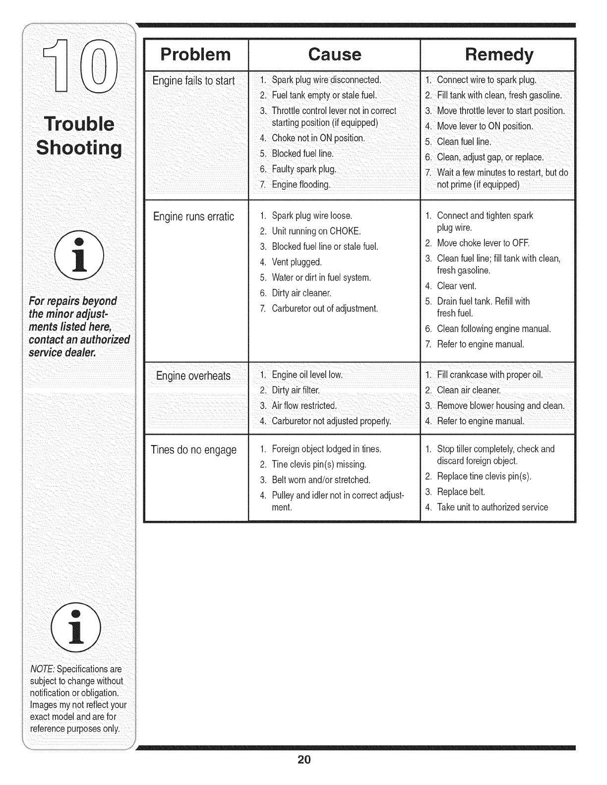
For repairs beyond
the minor
ments listed here,
contact an authorized
service dealer.
Problem Cause Remedy
Enginefailsto start Sparkplugwire disconneCte&
Eui! tank emptyoi stae fue!i 2 Fi!i!ankwith€leanifreshgaso!ine
3, Throttlecontrol!evernot incorrect & Movethrottle !everto start position
startingPosi! on(i! equipped)4 MoVeieveitOON position:
4, Chokenotin ON position, 5 ciean fuel line
5! B!°cked!ue!!inei 61 c!eanl adjustgaploireplace
Eau!tysparkp!ugl 7! Waitafew rninuteSt0 restart,but do
! Engine flooding, not prime(i! equipped)
Engineruns erratic 1. Sparkplugwire loose.
2. Unitrunningon CHOKE.
3. Blockedfuel lineor stalefuel.
4. Ventplugged.
5. Wateror dirt in fuel system.
6. Dirtyair cleaner.
7. Carburetorout of adjustment.
1. Connectandtightenspark
plugwire.
2. Movechokeleverto OFE
3. Cleanfuel line;fill tankwithclean,
freshgasoline.
4. Clearvent.
5. Drainfuel tank. Refillwith
freshfuel.
6. Cleanfollowingenginemanual.
7. Referto enginemanual.
Engine overheats ! Engne0ii !eyellow ! Fi!!CiankCaseWithpi0Peio! 1
I 2! Di[tYa!rfi!ter' 2: C!eana!rcleaner!
3 A rfow restrcted I 3 Removebower housng andc ean
. 4. Carburetornot adjustedproperly. .4, Referto enginemanual.
1. Foreignobjectlodgedintines.
2. Tineclevispin(s) missing.
3. Beltwornand/or stretched.
4. Pulleyandidlernot incorrectadjust-
ment.
1. Stop tillercompletely,checkand
discardforeignobject.
2. Replacefineclevis pin(s).
3. Replacebelt.
4. Takeunit to authorizedservice
Tines do no engage
NOTE: Specificationsare
subject to changewithout
notificationor obligation,
ImageSmynot reflect your
exact modelandarefor
referencepurpOseSonlyl
20
21
thisp_g_tom_k_
notes and write down
important information:
1-800_800,7310,or
1'330-220'4683,
www,mtdproducts.com
i i i i i i ii
ii i _iI_ ii
_iii _ii_i_i _!i i _iiiiiii_ii _i _
NOTE:specificationsare
subject to changewithout
notificationor obligationl
Irnagesrnynot reflect your
exact modelandarefor
referencepurposeson!y,
Use this page to make
notes and write down
For parts and/or
accessories
please call
1-800.800-7310,or
1-330-220-4683.
www.mtdproducts.com
NOTE:SPeCificationsaie
subject to changewithout
notificationorobligation.
Images mynot reflectyour
exact modelandarefoi
refeienCepurposeSonly
22

23
notes and write down
NOTE: Specificationsare
Subjectto changewithout
i0tiication orobligationl
!magesmy notreflectyour
modelandarefor
referenCepurP0sesonly.
MANUFACTURER'S LiMiTED WARRANTY FOR
The limitedwarrantysetforthbelowisgivenby MTDLLCwithrespect
to newmerchandisepurchasedandusedin the UnitedStates,its
possessionsandterritories.
"MTD"warrantsthisproductagainstdefectsinmaterialandworkman-
shipfor a periodof two (2)yearscommencingonthe date of original
purchaseandwill,at itsoption,repairor replace,freeof charge,any
part foundto bedefectiveinmaterialsorworkmanship.Thislimitedwar-
rantyshallonlyapply if thisproducthasbeenoperatedand maintained
inaccordancewiththe Operator'sManualfurnishedwiththe product,
andhas notbeensubjectto misuse,abuse,commercialuse,neglect,
accident,impropermaintenance,alteration,vandalism,theft,fire,water,
ordamagebecauseof otherperilor naturaldisaster.Damageresulting
fromthe installationor useof any part,accessoryor attachmentnot
approvedby MTDfor use withthe product(s)coveredbythis manual
willvoid yourwarrantyas to any resultingdamage.
Normalwearpartsarewarrantedto befree fromdefectsinmaterialand
workmanshipfor a periodof thirty (30)daysfromthe dateof purchase.
Normalwearpartsinclude,butare notlimitedto itemssuchas: batter-
ies,belts,blades,bladeadapters,grassbags,riderdeckwheels,seats,
snowthrowerskidshoes,shaveplates,augerspiralrubberandtires.
HOW TO OBTAIN SERVICE: Warranty service is available,WITH
PROOFOF PURCHASE, through your local authorized service
dealer. To locate the dealer in your area, check your Yellow Pages,
or contact MTD LLC at RO. Box 361131,Cleveland, Ohio 44136-
0019, or call 1-800-800-7310or 1-330-220-4683 or log on to our
Web site at www.mtdproducts.com.
Thislimitedwarrantydoesnot providecoverageinthe followingcases:
a. Theengineor componentpartsthereof.Theseitemsmaycarrya
separatemanufacturer'swarranty.Referto applicablemanufacturer's
warrantyfor termsandconditions.
b. Logsplitterpumps,valves,andcylindershavea separateoneyear
warranty.
c. Routinemaintenanceitemssuchas lubricants,filters,blade
sharpening,tune-ups,brakeadjustments,clutchadjustments,deck
adjustments,andnormaldeteriorationof the exteriorfinishdueto
useor exposure.
d. Servicecompletedby someoneotherthananauthorizedservice
dealer.
e. MTDdoesnot extendanywarrantyfor productssoldor exported
outsideof the UnitedStates,its possessionsandterritories,except
thosesoldthroughMTD'sauthorizedchannelsof exportdistribution.
f. ReplacementpartsthatarenotgenuineMTDparts.
g. Transportationchargesandservicecalls.
No impliedwarranty,includingany impliedwarranty of mer-
chantabilityof fitness for a particular purpose,applies after the
applicable periodof express written warranty above as to the
partsas identified.No otherexpresswarranty, whetherwrittenor
oral, except as mentioned above,givenby any personor entity,
includingadealeror retailer, withrespect to any product,shall
bindMTD.Duringthe periodof the warranty,the exclusiveremedy
is repairor replacementof the productas setforth above.
Theprovisionsas set forth inthis warrantyprovidethe soleand
exclusiveremedy arising from the sale.MTDshallnot be liable
for incidentalor consequentiallossor damage including,without
limitation, expensesincurredfor substituteor replacementlawn
careservicesor for rentalexpensesto temporarily replacea
warranted product.
Somestatesdo notallowthe exclusionor limitationof incidentalor
consequentialdamages,or limitationsonhowlongan impliedwarranty
lasts,sothe aboveexclusionsor limitationsmaynot applyto you.
In noeventshallrecoveryof any kindbegreaterthanthe amountof the
purchasepriceof the productsold.Alterationof safetyfeatures of
the productshallvoid this warranty. Youassumethe riskandliability
for loss,damage,or injuryto you andyourpropertyand/orto othersand
theirpropertyarisingout of the misuseor inabilityto usethe product.
Thislimitedwarrantyshallnot extendto anyoneotherthan theoriginal
purchaserorto the personfor whomitwas purchasedas a gift.
HOWSTATELAWRELATESTOTHIS WARRANTY:This limited
warrantygivesyou specificlegalrights,and youmayalsohaveother
rightswhichvaryfromstateto state.
IMPORTANT:OwnermustpresentOriginalProofof Purchaseto obtain
warrantycoverage.
IVITDLLC, P.O. BOX 361131 CLEVELAND, OHiO 44136-0019; Phone: 1=800=800-7310, 1-330=220-4683
GDOO-lO0015 REV.A
