MTD 24A 070J799 User Manual YARD VACUUM Manuals And Guides L0902219
MTD Lawn Vacuum Manual L0902219 MTD Lawn Vacuum Owner's Manual, MTD Lawn Vacuum installation guides
User Manual: MTD 24A-070J799 24A-070J799 MTD YARD VACUUM - Manuals and Guides View the owners manual for your MTD YARD VACUUM #24A070J799. Home:Lawn & Garden Parts:MTD Parts:MTD YARD VACUUM Manual
Open the PDF directly: View PDF ![]() .
.
Page Count: 64
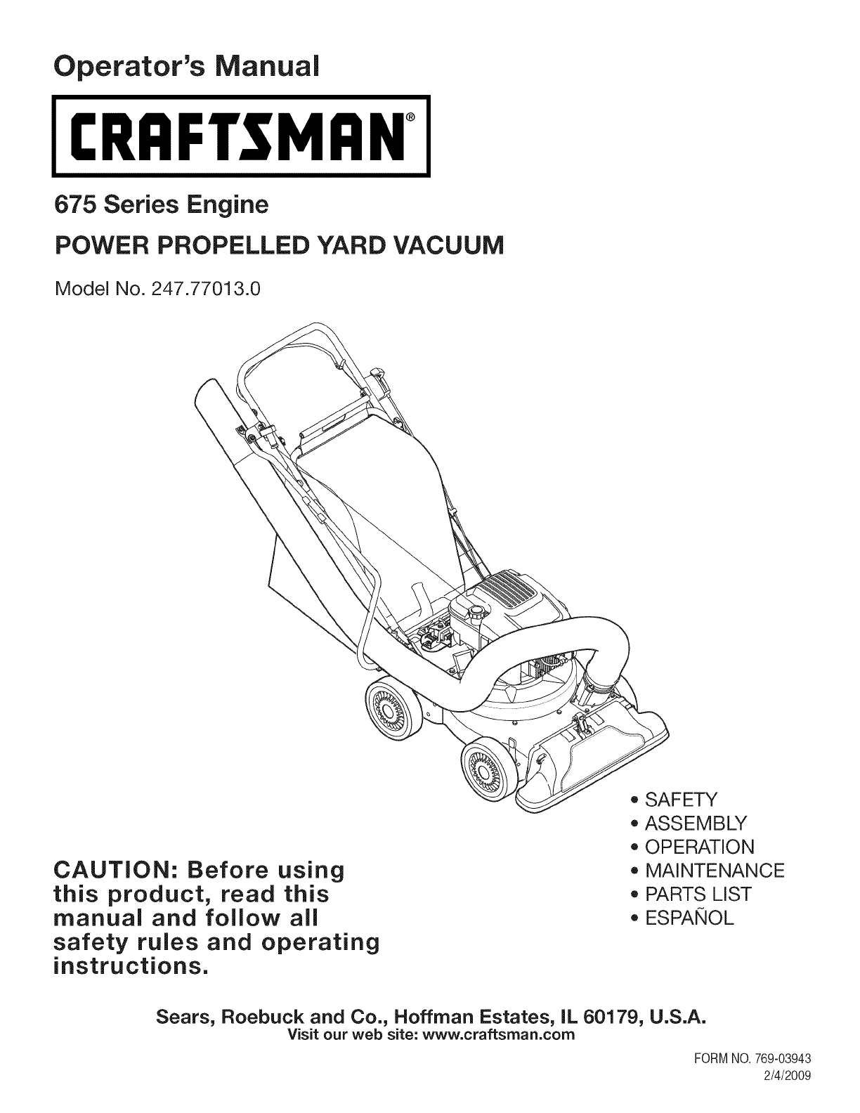
Operator's Manual
CRRF[SM ®
675 Series Engine
POWER PROPELLED YARD VACUUM
Model No. 247.77013.0
CAUTION: Before using
this product, read this
manual and follow all
safety rules and operating
instructions.
o SAFETY
ASSEMBLY
OPERATION
MAINTENANCE
PARTS LIST
o ESPANOL
Sears, Roebuck and Co., Hoffman Estates, IL 60179, U.S.A.
Visit our web site: www.craftsman.com
FORMNO.769-03943
2/4/2009
WarrantyStatement..................................Page2
SafeOperationPractices..........................Pages3-6
SafetyLabels............................................Page7
Assembly..................................................Pages8-11
Operation..................................................Pages12-15
ServiceandMaintenance.........................Pages16-21
Off-SeasonStorage..................................Page22
TroubleShooting.......................................Page23
PartsList...................................................Page24-33
RepairProtectionAgreement...................Page36
Espa_ol.....................................................Page37
ServiceNumbers......................................BackCover
OneYearFull Warranty on Craftsman Yard Vacuum
Thisequipmentis coveredby a one-yearwarranty,providedthatit is maintained,lubricated,andtunedupaccordingto the instructionsinthe
operator'smanual.Duringthewarrantyyear,if thisequipmentexperiencesanyfailuredueto defectsin materialor workmanship,RETURNITTO
YOURNEARESTSEARSPARTS& REPAIRCENTER,andSearswill repairit,free of charge.In-homewarrantyserviceis available,butyou will
haveto paya trip charge.
This warranty does not cover:
• Expendableitemswhichbecomewornduringnormaluse,suchas sparkplugs,aircleaners,belts,andoil filters.
• Tire replacementor repaircausedby puncturesfromoutsideobjects,suchas nails,thorns,stumps,or glass.
• Repairsnecessarybecauseof operatorabuse,includingbutnot limitedto,damagecausedbyobjects,suchas stones,metaldebrisor
oversizedpiecesof wood,or impactingobjectsthatbendtheframeor crankshaft,or over-speedingthe engine.
• Repairsnecessarybecauseof operatornegligence,includingbut not limitedto,electricalandmechanicaldamagecausedby improper
storage,failureto usethe propergradeandamountof engineoil, or failureto maintainthe equipmentaccordingto the instructionscontained
inthe operator'smanual.
• Engine(fuelsystem)cleaningor repairscausedbyfuel determinedto becontaminatedoroxidized(stale).In general,fuel shouldbeused
within30 daysof itspurchasedate.
• Equipmentifusedfor commercialor rentalpurposes.
Thiswarrantyappliesforonly 90daysifthis productiseverusedfor commercialor rentalpurposes.
Thiswarrantyappliesonly whilethisproductis usedinthe UnitedStates.
Thiswarrantygivesyou specificlegalrights,andyou mayalso haveotherrightswhichvaryfromstateto state.
Sears, Roebuck and Co., Hoffman Estates, IL 60179
EngineSeries: 675
EngineOilType: SAE30
EngineOilCapacity: 18ounces
FuelCapacity: 1 1/2 Quarts
SparkPlug: Champion®RJ19LM
SparkPlugGap: .020"
Model Number.................................................................
Serial Number .................................................................
Dateof Purchase.............................................................
Recordthe modelnumber,serialnumber
anddateof purchaseabove
©SearsBrands,LLC 2
Thissymbolpointsoutimportantsafetyinstructionswhich,
ifnotfollowed,couldendangerthepersonalsafetyand/
orpropertyofyourselfandothers.Readandfollowall
instructionsinthismanualbeforeattemptingtooperate
thismachine.Failuretocomplywiththeseinstructionsmay
resultinpersonalinjury.Whenyouseethissymbol,HEED
ITSWARNING!
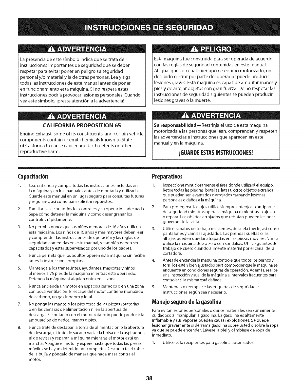
CALIFORNIA PROPOSITION 65
Engine Exhaust, some of its constituents, and certain vehicle
components contain or emit chemicals known to State
of California to cause cancer and birth defects or other
reproductive harm.
This machine was built to be operated according to the
safe operation practices in this manual. As with any type of
power equipment, carelessness or error on the part of the
operator can result in serious injury. This machine iscapable
of amputating fingers, hands, toes and feet and throwing
debris. Failure to observe the following safety instructions
could result in serious injury or death.
Your Responsibility--Restrict the use of this power
machine to persons who read, understand and follow
the warnings and instructions in this manual and on the
machine.
SAVETHESEINSTRUCTIONS!
Training Preparation
1. Read, understand, and follow all instructions on the machine
and in the manual(s) before attempting to assemble and
operate. Keep this manual in a safe place for future and regular
reference and for ordering replacement parts.
2. Be familiar with all controls and their proper operation. Know
how to stop the machine and disengage them quickly.
3. Never allow children under 16 years of age to operate this
machine. Children 16 and over should read and understand the
instructions and safe operation practices in this manual and on
the machine and be trained and supervised by an adult.
4. Never allow adults to operate this machine without proper
instruction.
5. Keep bystanders, pets, and children at least 75 feet from the
machine while it is in operation. Stop machine if anyone enters
the area.
6. Never run an engine indoors or in a poorly ventilated area.
Engine exhaust contains carbon monoxide, an odorless and
deadly gas.
7. Do not put hands and feet near rotating parts or in the feeding
chambers and discharge opening. Contact with the rotating
impeller can amputate fingers, hands, and feet.
8. Never attempt to unclog either the feed intake or discharge
opening, remove or empty bag, or inspect and repair the
machine while the engine is running. Shut the engine off and
wait until all moving parts have come to a complete stop.
Disconnect the spark plug wire and ground it against the
engine.
1. Thoroughly inspect the area where the equipment is to be
used. Remove all rocks, bottles, cans, or other foreign objects
which could be picked up or thrown and cause personal injury
or damage to the machine.
2. Always wear safety glasses or safety goggles during operation
and while performing an adjustment or repair, to protect your
eyes. Thrown objects which ricochet can cause serious injury
to the eyes.
3. Wear sturdy, rough-soled work shoes and close-fitting slacks
and shirts. Loose fitting clothes or jewelry can be caught in
movable parts. Never operate this machine in bare feet or
sandals. Wear leather work gloves when feeding material in
the chipper chute.
4. Before starting, check all bolts and screws for proper tightness
to be sure the machine is in safe working condition. Also,
visually inspect machine for any damage at frequent intervals.
5. Maintain or replace safety and instructions labels, as necessary.
3
SafeBandling of Gasoline:
To avoid personal injury or property damage use extreme care in
handling gasoline. Gasoline is extremely flammable and the vapors
are explosive. Serious personal injury can occur when gasoline is
spilled on yourself or your clothes which can ignite. Wash your skin
and change clothes immediately.
1. Use only an approved gasoline container.
2. Never fill containers inside a vehicle or on a truck or trailer bed
with a plastic liner. Always place containers on the ground
away from your vehicle before filling.
3. When practical, remove gas-powered equipment from
the truck or trailer and refuel it on the ground. If this is not
possible, then refuel such equipment on a trailer with a
portable container, rather than from a gasoline dispenser
nozzle.
4_
5_
6.
7.
Keep the nozzle in contact with the rim of the fuel tank or
container opening at all times until fueling is complete. Do not
use a nozzle lock-open device.
Extinguish all cigarettes, cigars, pipes and other sources of
ignition.
Never fuel machine indoors.
Never remove gas cap or add fuel while the engine is hot or
running. Allow engine to cool at least two minutes before
refueling.
8. Never over fill fuel tank. Fill tank to no more than 1/2inch below
bottom of filler neck to allow space for fuel expansion.
9. Replace gasoline cap and tighten securely.
10. If gasoline is spilled, wipe it off the engine and equipment. 13.
Move unit to another area. Wait 5 minutes before starting the
engine. 14.
11. To reduce fire hazards, keep machine free of grass, leaves, or
other debris build-up. Clean up oil or fuel spillage and remove 15.
any fuel soaked debris.
12. Never store the machine or fuel container inside where there is 16.
an open flame, spark or pilot light as on a water heater, space
heater, furnace, clothes dryer or other gas appliances. 17.
Operation
1. Do not put hands and feet near rotating parts or in the feeding
chambers and discharge opening. Contact with the rotating
impeller can amputate fingers, hands, and feet.
2. Before starting the machine, make sure the chipper chute, feed
intake, and cutting chamber are empty and free of all debris.
3. Thoroughly inspect all material to be shredded and remove
any metal, rocks, bottles, cans, or other foreign objects which
could cause personal injury or damage to the machine.
4. If the impeller strikes a foreign object or if your machine
should start making an unusual noise or vibration, immediately
shut the engine off. Allow the impeller to come to a complete
stop. Disconnect the spark plug wire, ground it against the
engine and perform the following steps:
a. Inspect for damage.
b. Repair or replace any damaged parts.
c. Check for any loose parts and tighten to assure
continued safe operation.
5. Do not allow an accumulation of processed material to build
up in the discharge area. This can prevent proper discharge
and result in kickback of material through the feed opening.
6. Do not attempt to shred or chip material larger than specified
on the machine or in this manual. Personal injury or machine
damage could result.
7. Never attempt to unclog either the feed intake or discharge
opening while the engine is running. Shut the engine off, wait
until all moving parts have stopped, disconnect the spark plug
wire and ground it against the engine before clearing debris.
8. Never operate without vacuum bag and discharge chute
properly attached to the machine. Never empty or change
vacuum bag while the engine is running. Zippered end of
vacuum bag must be kept closed at all times during operation.
9. Never operate without either the inlet nozzle or optional hose
attachment (if applicable) properly attached to the machine.
Never attempt to attach or change either attachment while the
engine is running.
10. Keep all guards, deflectors and safety devices in place and
operating properly.
11. Keep your face and body back and to the side of the chipper
chute while feeding material into the machine to avoid
accidental kickback injuries.
12. Never operate this machine without good visibility or light.
Always be sure of your footing and keep a firm hold on the
handles.
Do not operate this machine on a paved, gravel or non-level
surface.
Do not operate this machine while under the influence of
alcohol or drugs.
Muffler and engine become hot and can cause a burn. Do not
touch.
Never pick up or carry machine while the engine is running.
If situations occur which are not covered in this manual, use
care and good judgement. Contact Customer Support for
assistance and the name of the nearest service dealer.
Maintenance&Storage
1. Never tamper with safety devices. Check their proper
operation regularly.
2. Check bolts and screws for proper tightness at frequent
intervals to keep the machine in safe working condition. Also,
visually inspect machine for any damage and repair, if needed.
3. Before cleaning, repairing, or inspecting, stop the engine and
make certain the impeller and all moving parts have stopped.
Disconnect the spark plug wire and ground it against the
engine to prevent unintended starting.
4. Do not change the engine governor settings or overspeed the
engine. The governor controls the maximum safe operating
speed of the engine.
5. Maintain or replace safety and instruction labels, as necessary.
4
6. Follow this manual for safe loading, unloading, transporting,
and storage of this machine.
7. Never store the machine or fuel container inside where there
isan open flame, spark or pilot light such as a water heater,
furnace, clothes dryer, etc.
8. Allow machine to cool at least 5 minutes before storing.
9. Always refer to the operator's manual for proper instructions
on off-season storage.
10. If the fuel tank has to be drained, do this outdoors.
11. Observe proper disposal laws and regulations for gas, oil, etc.
to protect the environment.
12. According to the Consumer Products Safety Commission
(CPSC)and the U.S.Environmental Protection Agency (EPA),
this product has anAverage UsefulLife of seven (7) years, or
60 hours of operation. At the end of the Average Useful Life
have the machine inspected annually by an authorized service
dealer to ensure that all mechanical and safety systems are
working properly and not worn excessively. Failure to do so
can result in accidents, injuries or death.
Donot modifyengine
To avoid serious injury or death, do not modify engine in any way.
Tampering with the governor setting can lead to a runaway engine
and cause it to operate at unsafe speeds. Never tamper with factory
setting of engine governor.
Notice Regarding Emissions
Engines which are certified to comply with California and federal
EPA emission regulations for SORE (Small Off Road Equipment) are
certified to operate on regular unleaded gasoline, and may include
the following emission control systems: Engine Modification (EM),
Oxidizing Catalyst (OC), Secondary Air Injection (SAI) and Three Way
Catalyst (TWC) if so equipped.
SparkArrestor
This machine is equipped with an internal combustion engine and
should not be used on or near any unimproved forest-covered,
brushcovered or grass-covered land unless the engine's exhaust
system is equipped with a spark arrestor meeting applicable local
or state laws (if any)
Ira spark arrester is used, it should be maintained in effective
working order by the operator. In the State of California the above
is required by law (Section 4442 of the California Public Resources
Code). Other states may have similar laws. Federal laws apply on
federal lands.
A spark arrester for the muffler is available through your nearest
Sears Parts and Repair Service Center.
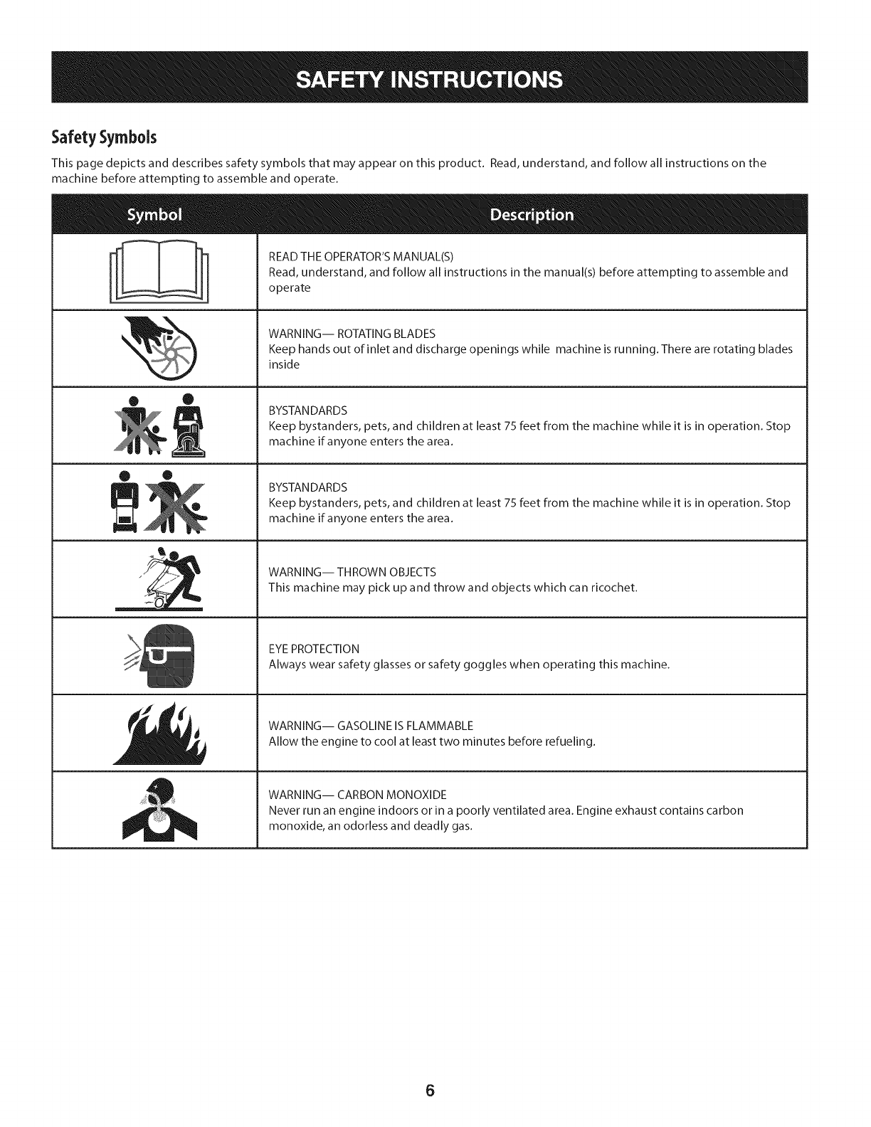
SafetySymbols
This page depicts and describes safety symbols that may appear on this product. Read, understand, and follow all instructions on the
machine before attempting to assemble and operate.
° I °_' READ THE OPERATOR'S MANUAL(S)
I
I
I
• ®
2
O ®
ill
i/
Read, understand, and follow all instructions in the manual(s) before attempting to assemble and
operate
WARNING-- ROTATING BLADES
Keep hands out of inlet and discharge openings while machine is running. There are rotating blades
inside
BYSTANDARDS
Keep bystanders, pets, and children at least 75 feet from the machine while it is in operation. Stop
machine if anyone enters the area.
BYSTANDARDS
Keep bystanders, pets, and children at least 75 feet from the machine while it is in operation. Stop
machine if anyone enters the area.
WARNING-- THROWN OBJECTS
This machine may pick up and throw and objects which can ricochet.
EYEPROTECTION
Always wear safety glasses or safety goggles when operating this machine.
WARNING-- GASOLINE IS FLAMMABLE
Allow the engine to cool at least two minutes before refueling.
WARNING-- CARBON MONOXIDE
Never run an engine indoors or in a poorly ventilated area. Engine exhaust contains carbon
monoxide, an odorless and deadly gas.
6
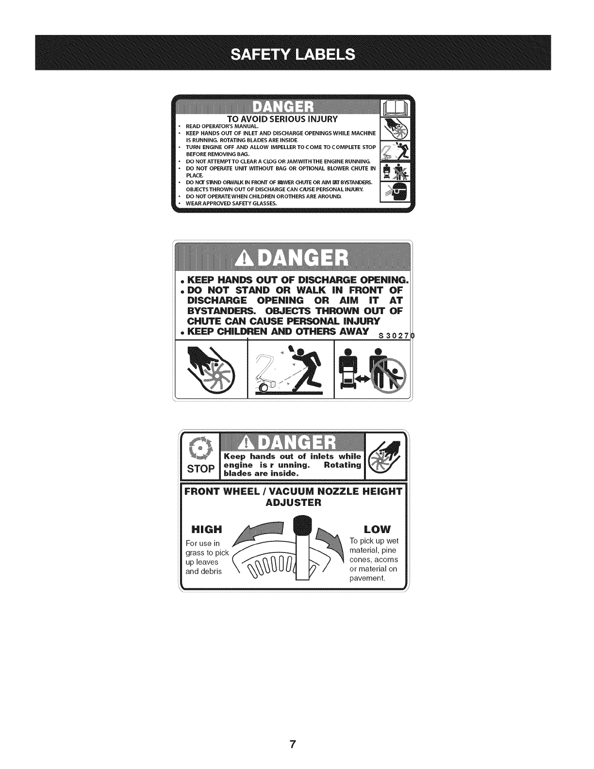
TO AVOID SERIOUS iNJURY
READ OPERATOR'S MANUAL.
KEEP HANDS OUT OF iNLET AND DISCHARGE OPENINGS WHILE MACHINE
iS RUNNING. ROTATING BLADES ARE iNSiDE
TURN ENGINE OFF AND ALLOW iMPELLER TOCOME TOCOMPLETE STOP
BEFORE REMOVING BAG.
DO NOT ATTEMPT TO CLEAR A CLOG OR JAMWJTH THE ENGINE RUNNING.
DO NOT OPERATE UNiT WITHOUT RAG OR OPTIONAL RLOWER CHUTE iN
PLACE.
I•DONO/'S'_NDOBWALKINFRONTOFI_WERCHUTEORAJMB_TBYSTANDERS.
I
I OBJECTS THROWN OUT OF DISCHARGE CAN C/USE PERSONAL iNJURY.
=========_===
I• DO NOT OPERATEWHEN CHILDREN OROTHERS ARE AROUND,
"WEARAPPROVED SAFETYGLASSES.
.KEEP HANDS OUT OF DISCHARGE OPENING.
. DO NOT STAND OR WALK iN FRONT OF
DISCHARGE OPENING OR AiM iT AT
BYSTANDERS. OBJECTS THROWN OUT OF
CHUTE CAN CAUSE PERSONAL iNJURY
. KEEP CHILDREN AND OTHERS AWAY $ 3 o2
®
FRONT WHEEL /VACUUM NOZZLE HEIGHT
ADJUSTER
7
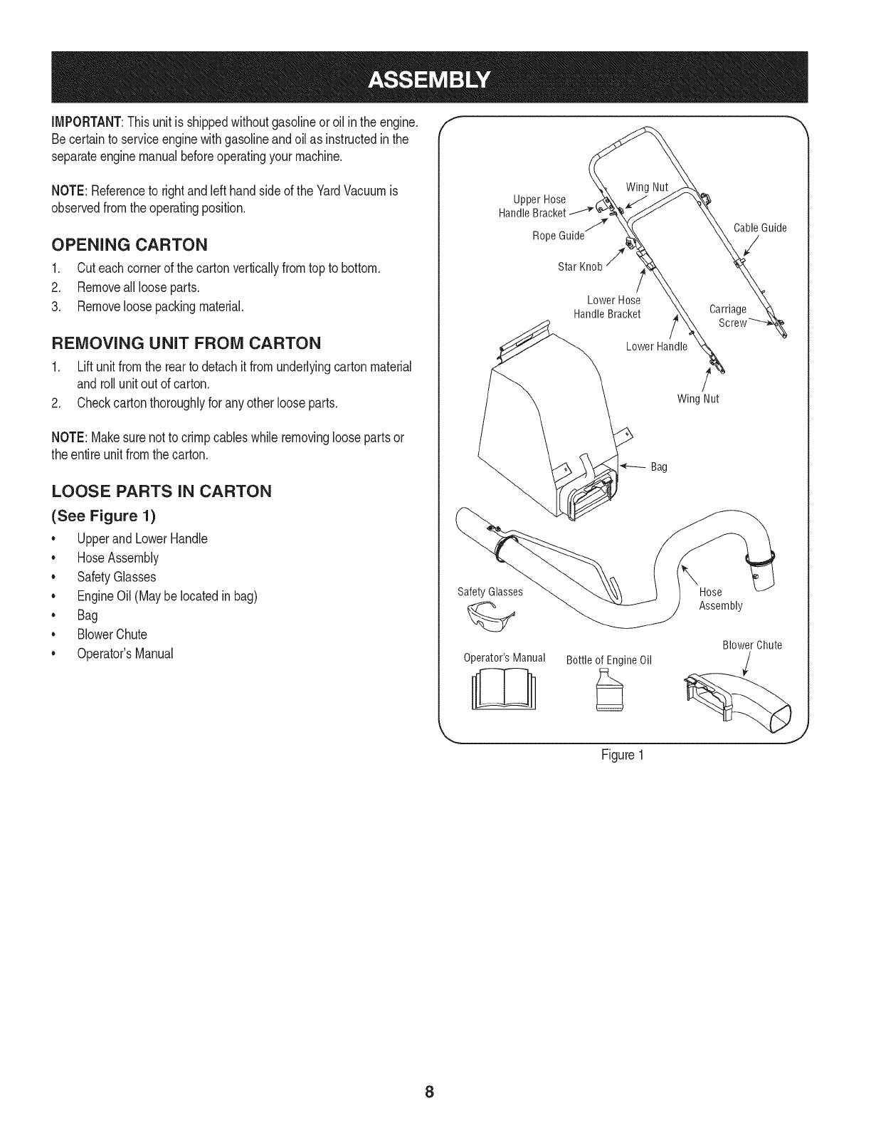
IMPORTANT:Thisunit is shippedwithoutgasolineoroil inthe engine.
Becertainto serviceenginewithgasolineandoilas instructedinthe
separateenginemanualbeforeoperatingyourmachine.
NOTE:Referenceto rightand lefthandsideof the YardVacuumis
observedfromthe operatingposition.
OPENING CARTON
1. Cuteachcornerof the cartonverticallyfromtop to bottom.
2. Removeall looseparts.
3. Removeloosepackingmaterial.
REMOVING UNIT FROM CARTON
1. Liftunit fromthe rearto detachit fromunderlyingcartonmaterial
androllunit out of carton.
2. Checkcartonthoroughlyfor anyotherlooseparts.
NOTE:Makesurenot to crimpcableswhile removingloosepartsor
theentire unitfromthecarton.
LOOSE PARTS IN CARTON
(See Figure 1)
• Upperand LowerHandle
• HoseAssembly
• SafetyGlasses
• EngineOil(Maybelocatedinbag)
• Bag
• BlowerChute
• Operator'sManual
Upper Hose
Handle Bracket _
Rope Guidejj_
Star
Wing Nut
Lower Hose
HandleBracket
Lower Handle
Safety Glasses
Operator's Manual Bottle of Engine Oil
CableGuide
Carriage
Wing Nut
\Hose
Assembly
Blower Chute
Figure1
8
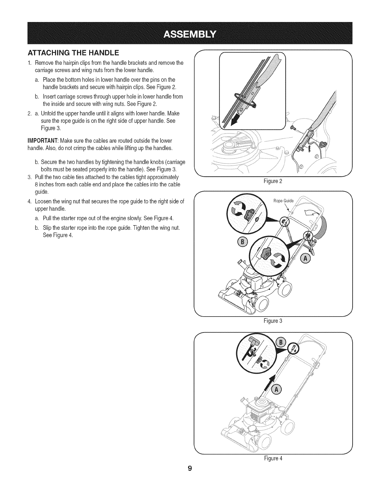
ATTACHING THE HANDLE
1. Removethehairpinclipsfromthe handlebracketsand removethe
carriagescrewsandwingnutsfromthe lowerhandle.
a. Placethe bottomholesinlowerhandleoverthe pinson the
handlebracketsand securewith hairpinclips. SeeFigure2.
b. insertcarriagescrewsthroughupperholeinlowerhandlefrom
the insideandsecurewithwingnuts.SeeFigure2.
2. a. Unfoldthe upperhandleuntil italignswithlowerhandle.Make
surethe ropeguideis onthe rightside of upperhandle.See
Figure3.
IMPORTANT:Makesurethe cablesareroutedoutsidethe lower
handle.Also,donot crimpthe cableswhile liftingupthe handles.
.
.
b. Securethe two handlesbytighteningthe handleknobs(carriage
boltsmustbeseatedproperlyintothe handle).See Figure3.
Pullthetwo cabletiesattachedto the cablestightapproximately
8 inchesfromeachcableendandplacethe cablesintothe cable
guide.
Loosenthe wingnut thatsecuresthe ropeguideto the rightsideof
upperhandle.
a. Pullthe starterropeout of the engineslowly.SeeFigure4.
b. Slipthe starterropeinto the ropeguide.Tightenthe wingnut.
SeeFigure4.
Figure2
Rope Guide
Figure3
J
9
Figure4
J
f
Figure5
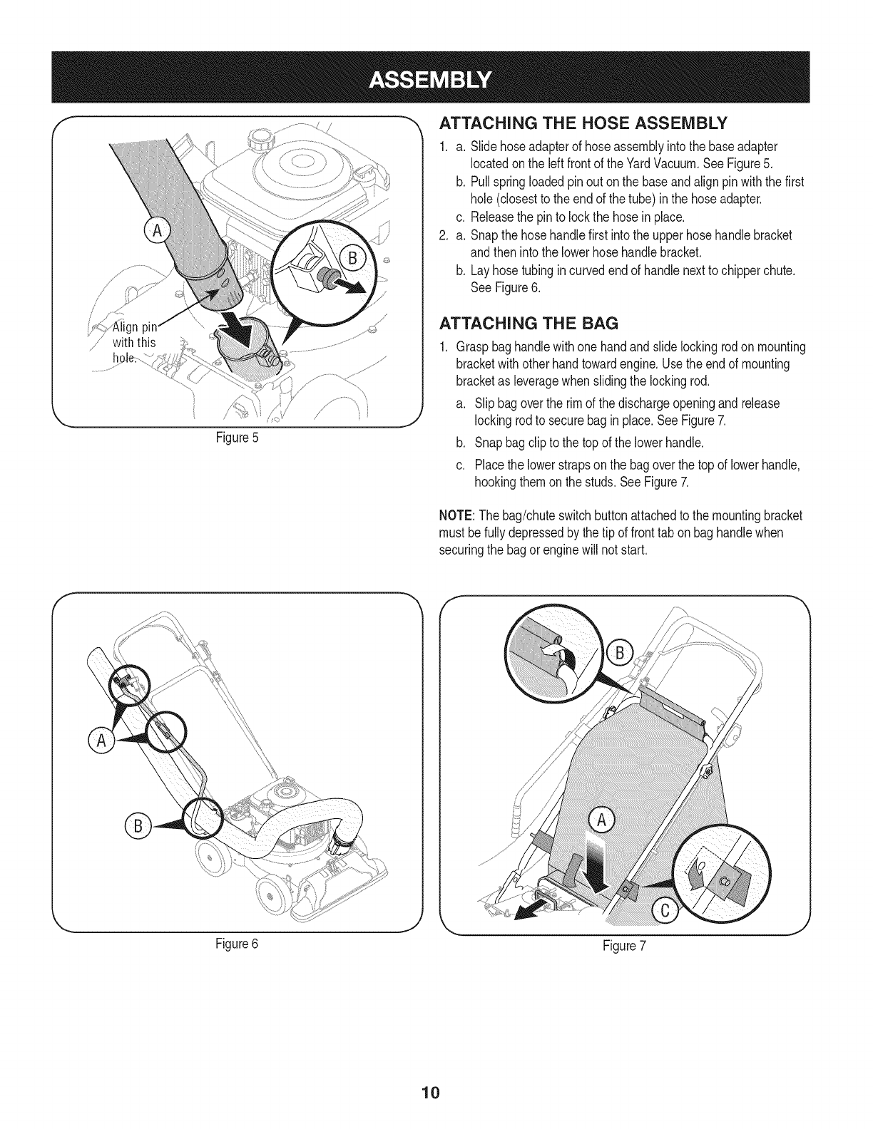
_, ATTACHING THE HOSE ASSEMBLY
1. a. Slidehoseadapterof hoseassemblyintothe baseadapter
locatedon the leftfrontof theYardVacuum.SeeFigure5.
b. Pullspringloadedpinout on the baseandalignpinwiththe first
hole(closestto the endof the tube) inthe hoseadapter.
c. Releasethe pinto lockthe hosein place.
2. a. Snapthe hosehandlefirst intothe upperhose handlebracket
andthen intothe lowerhosehandlebracket.
b. Layhosetubingincurvedendof handlenextto chipperchute.
SeeFigure6.
ATTACHING THE BAG
Graspbaghandlewithonehandandslide lockingrodonmounting
bracketwith otherhandtowardengine.Usethe endof mounting
bracketas leveragewhenslidingthe lockingrod.
a. Slipbagoverthe rim of the dischargeopeningandrelease
lockingrodto securebagin place.SeeFigure7.
b. Snapbagclipto the topof the lowerhandle.
c. Placethe lowerstrapson the bagoverthe topof lowerhandle,
hookingthemon the studs.SeeFigure7.
NOTE:The bag/chuteswitchbuttonattachedto the mountingbracket
must befullydepressedby thetip of fronttab on baghandlewhen
securingthe bagorenginewill not start.
Figure6 Figure7
10
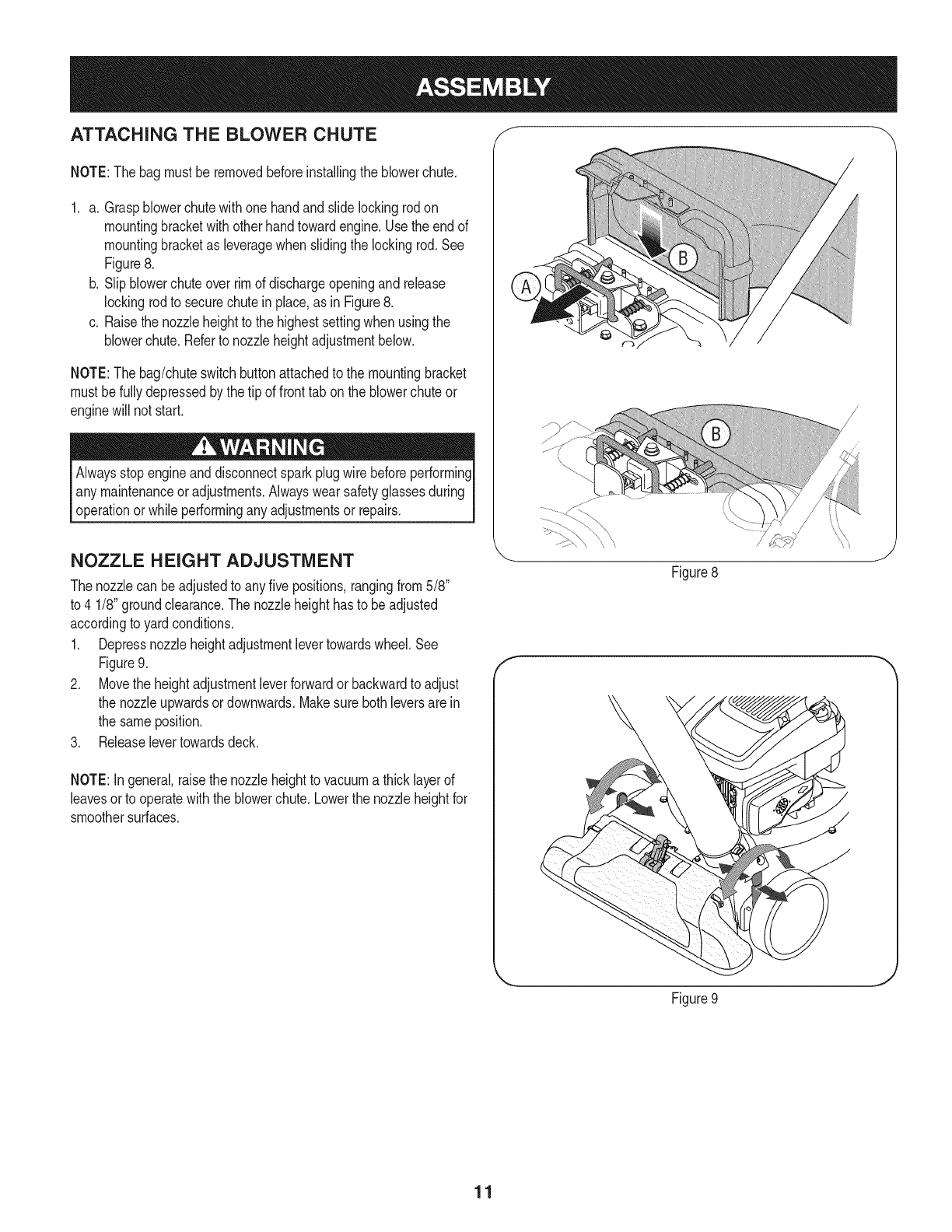
ATTACHING THE BLOWER CHUTE f
NOTE:Thebagmust beremovedbeforeinstallingthe blowerchute.
1. a. Graspblowerchutewithone handandslide lockingrodon
mountingbracketwithotherhandtowardengine.Usethe endof
mountingbracketas leveragewhenslidingthe lockingrod.See
Figure8.
b. Slipblowerchuteoverrimof dischargeopeningandrelease
lockingrodto securechutein place,as in Figure8.
c. Raisethe nozzleheightto the highestsettingwhen usingthe
blowerchute.Referto nozzleheightadjustmentbelow.
NOTE:Thebag/chuteswitchbuttonattachedto the mountingbracket
mustbefullydepressedbythe tip of fronttab onthe blowerchuteor
enginewill not start.
Alwaysstopengineanddisconnectsparkplugwire beforeperforming
any maintenanceoradjustments.Alwayswear safetyglassesduring
operationor whileperformingany adjustmentsor repairs.
NOZZLE HEIGHT ADJUSTMENT
Thenozzlecan beadjustedto anyfive positions,rangingfrom5/8"
to 4 1/8" groundclearance.The nozzleheighthasto be adjusted
accordingto yardconditions.
1. Depressnozzleheightadjustmentlevertowardswheel.See
Figure9.
2. Movethe heightadjustmentleverforwardor backwardto adjust
the nozzleupwardsordownwards.Makesure bothleversarein
the sameposition.
3. Releaselevertowardsdeck.
NOTE:In general,raisethe nozzleheightto vacuuma thicklayerof
leavesorto operatewiththeblowerchute.Lowerthe nozzleheightfor
smoothersurfaces.
f
Figure8
J
Figure9
J
11

fDrive Control
Speed Thn Control Choke Control
Starter
Lower
Hose
Bracket
HoseAssembl_
Hose Handle
Blower Chipper
Chute Chute
Bag
BagHandle
Oil Fill
GasolineFill
Plug Wire
Nozzle/Hose
Lever
Nozzle
Nowthat youhavesetup youryardvacuumfor operation,get
acquaintedwith itscontrolsandfeatures.Thesearedescribedbelow
andillustratedon thispage.Thisknowledgewill allowyou to useyour
newequipmentto its fullestpotential.
Theoperationof anyyard vacuumcan resultinforeignobjectsbeing
thrownintothe eyes,whichcan damageyoureyesseverely.Always
I wearthe safetyglassesprovidedwiththisunit oreye shieldswhile
[operatingor performinganyadjustmentsor repairson it.
NozzleHeig
Adjustment Lever J
Figure10
iMPORTANT:Movethe speedcontrolonlywhenthe engineis
running.Changingthe speedcontrolsettingwiththeengineoffcan
damagethe yardvacuum.
CHIPPER CHUTE
Allowstwigsandsmallbranchesupto 1-1/2"in diameterto be fed into
the impellerfor chipping.SeeFigure10.
DRIVE CONTROL
Locatedon the undersideof the upperhandle,the drivecontrolis used
to engage/disengagewheels.Fullysqueezethe drivecontrolagainst
the upperhandleto engagethe wheels;releaseto disengage.(DO
NOTslip clutch).
SPEED CONTROL
Locatedon the leftside of the upperhandle,the speedcontrolis used
to selectthe forwardspeedof the yardvacuum.
NOZZLE HEIGHT ADJUSTMENT LEVER
Usedto adjustthe nozzlegroundclearancerangingapproximately
from5/8"to 4 1/8".See Figure10.
NOZZLE
Yardwastesuchas leavesorpineneedlescan bevacuumedup
throughthe nozzlefor shredding.
HOSE ASSEMBLY
Usedas analternativeto thenozzleto vacuumyardwastesuchas
leavesor pineneedlesin hardto reachplaces.SeeFigure10.
NOZZLE/HOSE VAC LEVER
The nozzle/hosevachandleis locatedon topof the nozzle.Useit to
switchvacuumsuctionbetweenthe nozzleandthe hoseassembly.
HOSE HANDLE
Usedto guidehoseassemblywhenvacuuming.
Meets ANSI Safety Standards
CraftsmanYardVacuumsconformto the safetystandardof the AmericanNationalStandardsinstitute(ANSi).
12
BAG HANDLE
Usedto grasp baginorderto assistinattaching,removing,and
emptyingbag,SeeFigure10,
BAG
Collectsshreddedmaterialfed throughthe chipperchuteorvacuumed
throughthe nozzleor hose.
BLOWER CHUTE
Whenattachedto unit,the blowerchuteisusedto dischargeyard
wastesuchas leaves,pineneedle,or smalltwigsacrossyard.
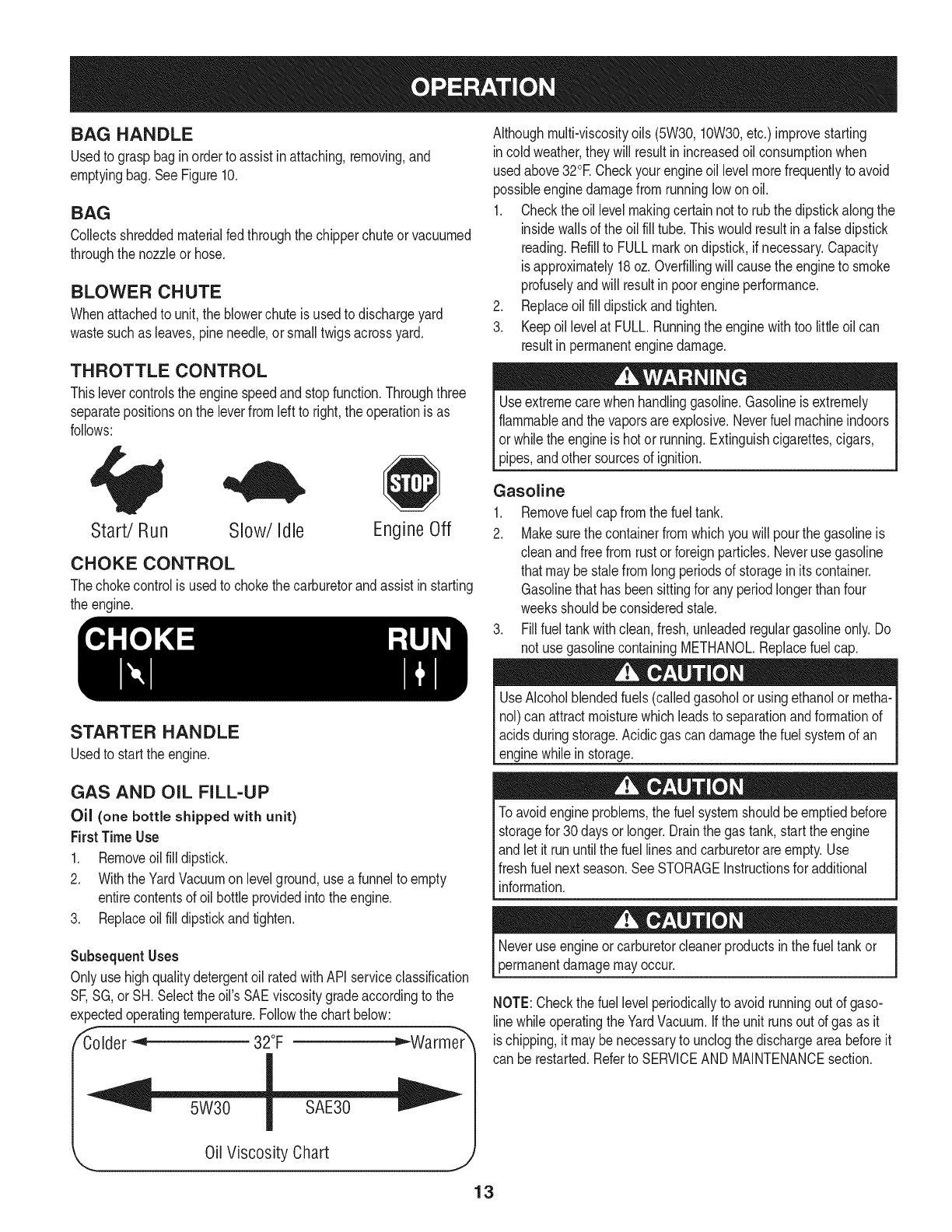
THROTTLE CONTROL
Thislevercontrolsthe enginespeedandstopfunction.Throughthree
separatepositionson the leverfromleft to right,the operationisas
follows:
Althoughmulti-viscosityoils (5W30,10W30,etc.)improvestarting
incoldweather,theywill resultin increasedoilconsumptionwhen
usedabove32°E Checkyourengineoil levelmorefrequentlyto avoid
possibleenginedamagefromrunninglow onoil.
1. Checkthe oillevel makingcertainnotto rubthedipstickalongthe
insidewallsof the oilfill tube.Thiswouldresultin afalsedipstick
reading.Refillto FULLmarkondipstick,if necessary.Capacity
isapproximately18oz.Overfillingwill causethe engineto smoke
profuselyandwill resultin poorengineperformance.
2. Replaceoil fill dipstickandtighten.
3. Keepoillevelat FULL.Runningthe enginewithtoo littleoil can
resultin permanentenginedamage.
Useextremecarewhen handlinggasoline.Gasolineis extremely
flammableand thevaporsare explosive.Neverfuel machineindoors
or whilethe engineis hot or running.Extinguishcigarettes,cigars,
pipes,andother sourcesof ignition.
Start/Run Slow/Idle Engine Off
CHOKE CONTROL
Thechokecontrolis usedto chokethe carburetorandassistinstarting
the engine.
STARTER HANDLE
Usedto startthe engine.
GAS AND OIL FILL-UP
Oil (one bottle shipped with unit)
First TimeUse
1. Removeoilfill dipstick.
2. WiththeYardVacuumon levelground,usea funnelto empty
entirecontentsof oil bottleprovidedintothe engine.
3. Replaceoilfill dipstickandtighten.
Gasoline
1. Removefuel capfromthe fueltank.
2. Makesurethe containerfromwhichyou will pourthe gasolineis
cleanandfree fromrustorforeignparticles.Neverusegasoline
thatmaybe stalefromlongperiodsof storageinitscontainer.
Gasolinethathas beensittingfor any periodlongerthan four
weeksshouldbeconsideredstale.
3. Fillfuel tankwithclean,fresh,unleadedregulargasolineonly.Do
notuse gasolinecontainingMETHANOL.Replacefuelcap.
UseAlcoholblendedfuels(calledgasoholorusingethanolormetha-
nol)can attractmoisturewhichleadsto separationandformationof
acidsduringstorage.Acidicgascan damagethe fuel systemof an
enginewhileinstorage.
Toavoidengineproblems,thefuel systemshouldbeemptiedbefore
storagefor30 daysorlonger.Drainthe gas tank,start theengine
andlet it rununtilthe fuel linesandcarburetorareempty.Use
freshfuelnextseason.SeeSTORAGEInstructionsfor additional
nformaton.
Subsequent Uses
Onlyuse highqualitydetergentoil ratedwithAPIserviceclassification
SF,SG,or SH.Selectthe oil'sSAEviscositygradeaccordingto the
expectedoperatingtemperature.Followthe chartbelow:
/_Colder_ 32°F _Warme_
OilViscosity Chart J
mayoccur.
NOTE:Checkthe fuellevel periodicallyto avoidrunningout of gaso-
linewhile operatingthe YardVacuum.Ifthe unit runsout of gas as it
ischipping,it maybe necessaryto unclogthe dischargeareabeforeit
can be restarted.Referto SERVICEANDMAINTENANCEsection.
13
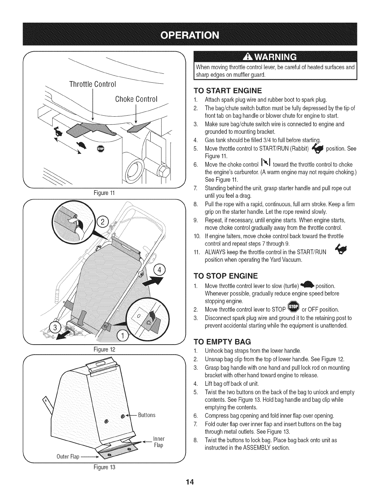
ThrottleControl
ChokeControl
Figure11
f
Whenmovingthrottlecontrollever,becarefulof heatedsurfacesand
sharpedgeson mufflerguard.
TO START ENGINE
1. Attachsparkplugwire andrubberbootto sparkplug.
2. The bag/chuteswitchbuttonmustbefullydepressedbythe tip of
fronttab on baghandleor blowerchutefor engineto start.
3. Makesurebag/chuteswitchwire is connectedto engineand
groundedto mountingbracket.
4. Gas tankshouldbe filled3/4 to full beforestarting.
5. Movethrottlecontrolto START/RUN(Rabbit) _ position.See
Figure11.
6. Movethechokecontrol I'_'1 towardthe throttlecontrolto choke
the engine'scarburetor.(Awarmenginemaynot requirechoking.)
See Figure11.
7. Standingbehindthe unit,graspstarterhandleandpull ropeout
until youfeel adrag.
8. Pullthe ropewitha rapid,continuous,full arm stroke.Keepa firm
gripon the starterhandle.Letthe roperewindslowly.
9. Repeat,if necessary,untilenginestarts.Whenenginestarts,
movechokecontrolgraduallyawayfromthe throttlecontrol.
10. Ifenginebiters, movechokecontrolbacktowardthe throttle
controland repeatsteps7 through9. ,t',,_
11. ALWAYSkeepthe throttlecontrolinthe START/RUN
positionwhenoperatingthe YardVacuum.
TO STOP ENGINE
1. Movethrottlecontrolleverto slow(turtle)_ position.
Wheneverpossible,graduallyreduceenginespeedbefore
stoppingengine.
2. Movethrottlecontrolleverto STOP or OFFposition.
3. Disconnectsparkplugwireand groundit to the retainingpostto
preventaccidentalstartingwhilethe equipmentis unattended.
Figure12
Outer Flal
Figure13
inner
Flap
TO EMPTY BAG
1. Unhookbagstrapsfromthe lowerhandle.
2. Unsnapbagclip fromthetop of lowerhandle.See Figure12.
3. Graspbaghandlewithonehandandpulllock rodonmounting
bracketwith otherhandtowardengineto release.
4. Liftbagoffbackof unit.
5. Twistthe twobuttonsonthe backof the bagto unlockandempty
contents.SeeFigure13.Holdbaghandleand bagclip while
emptyingthe contents.
6. Compressbagopeningandfold innerflap overopening.
7. Foldouter flapoverinnerflapand insertbuttonsonthe bag
throughmetaloutlets.SeeFigure13.
8. Twistthe buttonsto lockbag.Placebagbackonto unitas
instructedinthe ASSEMBLYsection.
14
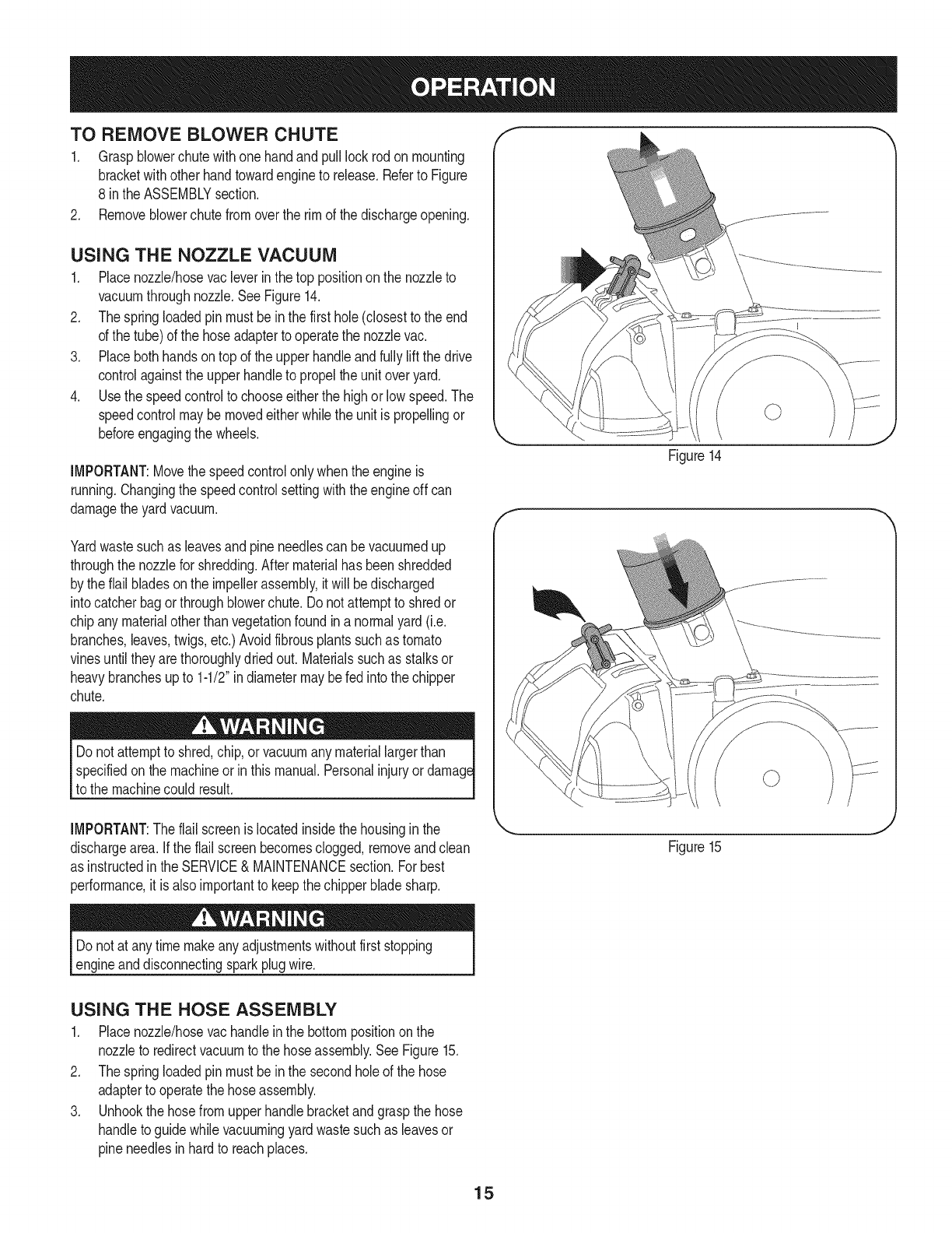
TO REMOVE BLOWER CHUTE
1. Graspblowerchutewithone handandpull lockrodonmounting
bracketwithotherhandtowardengineto release.Referto Figure
8 inthe ASSEMBLYsection.
2. Removeblowerchutefromoverthe rim of the dischargeopening.
USING THE NOZZLE VACUUM
1. Placenozzle/hosevacleverinthe top positionon the nozzleto
vacuumthroughnozzle.SeeFigure14.
2. Thespringloadedpinmustbein the first hole(closestto the end
of the tube)of the hoseadapterto operatethe nozzlevac.
3. Placebothhandsontop of the upperhandleandfullyliftthe drive
controlagainstthe upperhandleto propelthe unitoveryard.
4. Usethe speedcontrolto chooseeitherthe highor low speed.The
speedcontrolmaybemovedeitherwhilethe unitis propellingor
beforeengagingthewheels.
IMPORTANT:Movethe speedcontrolonlywhenthe engineis
running.Changingthe speedcontrolsettingwiththe engineoff can
damagethe yardvacuum.
Yardwastesuchas leavesandpineneedlescan bevacuumedup
throughthe nozzlefor shredding.Aftermaterialhas beenshredded
by theflail bladesonthe impellerassembly,it will bedischarged
intocatcherbagorthroughblowerchute.Do notattemptto shredor
chipany materialotherthan vegetationfoundin a normalyard(i.e.
branches,leaves,twigs,etc.)Avoidfibrousplantssuchas tomato
vinesuntil theyarethoroughlydriedout. Materialssuchas stalksor
heavybranchesupto 1-1/2"indiametermaybe fedinto thechipper
chute.
specifiedonthe machineorin thismanual.Personalinjuryor
to the machinecould result.
IMPORTANT:Theflail screenis locatedinsidethe housingin the
dischargearea. Ifthe flail screenbecomesclogged,removeandclean
as instructedin the SERVICE&MAINTENANCEsection.Forbest
performance,it is alsoimportantto keepthe chipperbladesharp.
Figure14
Figure15
J
Do notat any timemakeanyadjustmentswithoutfirststopping
engineanddisconnectingsparkplugwire.
USING THE HOSE ASSEMBLY
1. Placenozzle/hosevachandleinthe bottompositiononthe
nozzleto redirectvacuumto the hoseassembly.SeeFigure15.
2. Thespringloadedpinmustbein the secondholeof the hose
adapterto operatethe hoseassembly.
3. Unhookthe hosefromupperhandlebracketandgraspthe hose
handleto guidewhilevacuumingyardwastesuchas leavesor
pineneedlesin hardto reachplaces.
15
Alwaysstopengineanddisconnectsparkplugwire beforeperforming
I anymaintenanceoradjustments.Alwayswear safetyglassesduring
_operationor whileperforminganyadjustmentsor repairs.
GENERAL RECOMMENDATIONS
•Alwaysobservesafetyruleswhenperforming
anymaintenance.
• Thewarrantyon thisyardvacuumdoes notcoveritemsthat have
beensubjectedto operatorabuseor negligence.To receivefull
valuefromwarranty,operatormustmaintaintheequipmentas
instructedhere.
• Someadjustmentswillhaveto be madeperiodicallyto maintain
yourunit properly.
• Periodicallycheckall fastenersand makesurethesearetight.
f Electrode Porcelain
,<----.020 inch(.51ram)gap
_. .,Y
Figure16
ENGINE MAINTENANCE
Checking the Spark Plug
Cleansparkplugandresettheelectrodegapto 0.020"at leastonce a
season;replaceevery100hoursof operation.
Cleanareaaroundthe sparkplugbase.Do not sandblastspark
plug.Sparkplugshouldbecleanedby scrapingorwire brushing
andwashingwitha commercialsolvent.
Removeand inspectthe sparkplug.Checkgapto makesureit is
setat .020".SeeFigure16.
Replacethe sparkplugif electrodesarepitted,burned,or the
porcelainis cracked.
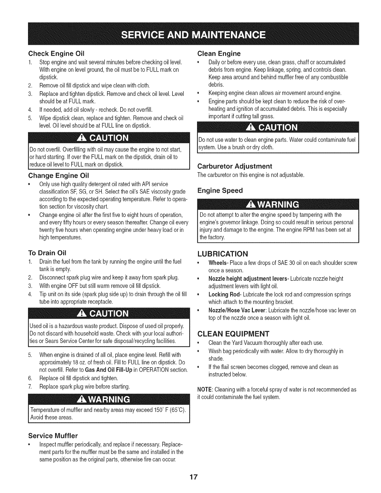
Servicing the Air Cleaner
Do notuse pressurizedair or solventsto cleanthe aircleaner
cartridge.
Theair cleanerpreventsdamagingdirt, dust,etc.,fromenteringthe
carburetorandbeingforcedintothe engineandis importantto engine
lifeand performance.Theair cleanerconsistsof a pleatedfilter.Never
runthe enginewithoutan aircleanercompletelyassembled.
Cleanor replacetheair cleanerevery25hoursof operation.
1. Loosenscrewandtilt plastichousingcoveron sideof engine
down.See Figure17.
2. Removeair filterfromplastichousingcoverandreplacewith
cleanor newfilter.
3. Insertcover'stabsintoslots in bottomof base.
4. Tiltcoverupintoplaceandtightenscrew.
NOTE:If thefilteris torn ordamagedin anyway,replaceit.
\
Figure17 .J
16
Check Engine Oil
1. Stopengineandwaitseveralminutesbeforecheckingoil level.
Withengineonlevelground,the oil mustbeto FULLmarkon
dipstick.
2. Removeoilfill dipstickandwipeclean withcloth.
3. Replaceandtightendipstick.Removeandcheckoil level.Level
shouldbeat FULLmark.
4. if needed,addoil slowly- recheck.Do notoverfill.
5. Wipedipstickclean,replaceandtighten.Removeandcheckoil
level.Oil levelshouldbe at FULLlineondipstick.
Donotoverfil.Overfillingwithoil maycausetheengineto not start,
or hardstarting.Ifoverthe FULLmarkonthe dipstick,drainoil to
reduceoillevelto FULLmarkon dipstick.
Change Engine Oil
•Onlyuse highqualitydetergentoil ratedwithAPIservice
classificationSF,SG, orSH.Selecttheoil's SAEviscositygrade
accordingto the expectedoperatingtemperature.Refertoopera-
tion sectionfor viscositychart.
• Changeengineoil afterthe first fiveto eighthoursof operation,
andeveryfifty hoursoreveryseasonthereafter.Changeoil every
twentyfivehourswhenoperatingengineunderheavyloadorin
hightemperatures.
Clean Engine
• Dailyor beforeeveryuse,cleangrass,chaff oraccumulated
debrisfromengine.Keeplinkage,spring,andcontrolsclean.
Keepareaaroundand behindmufflerfree of anycombustible
debris.
• Keepingenginecleanallowsair movementaroundengine.
• Enginepartsshouldbekeptcleanto reducethe riskof over-
heatingandignitionof accumulateddebris.Thisis especially
importantif cuttingtall grass.
Donot usewaterto cleanengineparts.Watercouldcontaminatefuel
system.Usea brushor dry cloth.
Carburetor Adjustment
The carburetoron thisengineis notadjustable.
Engine Speed
Donot attempttoalter the enginespeedbytamperingwiththe
engine'sgovernorlinkage.Doingso couldresultinseriouspersonal
injuryanddamageto theengine.TheengineRPMhasbeensetat
the factory.
To Drain Oil
1. Drainthe fuelfromthe tankby runningthe engineuntil thefuel
tankis empty.
2. Disconnectsparkplugwireandkeepit awayfromsparkplug.
3. WithengineOFFbutstillwarmremoveoil fill dipstick.
4. Tip uniton itsside (sparkplugside up)to drainthroughthe oilfill
tubeinto appropriatereceptacle.
Usedoil is a hazardouswasteproduct.Disposeof usedoil properly.
Donotdiscardwith householdwaste.Checkwithyourlocalauthori-
tiesor SearsServiceCenterfor safedisposal/recyclingfacilities.
5. Whenengineis drainedof all oil, placeenginelevel.Refillwith
approximately18oz.of freshoil. Fill to FULLlineon dipstick.Do
not overfill.Referto Gas And Oil Fill-Upin OPERATIONsection.
6. Replaceoilfill dipstickandtighten.
7. Replacesparkplugwirebeforestarting.
Temperatureof mufflerand nearbyareasmayexceed150° F (65°C).
Avoidtheseareas.
LUBRICATION
• Wheels- Placea fewdropsof SAE30oil oneach shoulderscrew
oncea season.
• Nozzleheightadjustment levers-Lubricatenozzleheight
adjustmentleverswithlightoil.
• Locking Rod- Lubricatethe lockrodandcompressionsprings
whichattachto the mountingbracket.
• Nozzle/HoseVac Lever: Lubricatethenozzle/hosevacleveron
top of the nozzleoncea seasonwithlightoil.
CLEAN EQUIPMENT
• Cleanthe YardVacuumthoroughlyaftereachuse.
• Washbagperiodicallywithwater.Allowto dry thoroughlyin
shade.
• Ifthe flail screenbecomesclogged,removeandcleanas
instructedbelow.
NOTE:Cleaningwitha forcefulsprayof wateris not recommendedas
it couldcontaminatethe fuel system.
Service Muffler
•Inspectmufflerperiodically,and replaceif necessary.Replace-
mentpartsfor the mufflermustbethe sameand installedin the
samepositionas the originalparts,otherwisefire canoccur.
17
Beforeperforminganytype of maintenanceon the machine,waitfor
allpartsto stopmovinganddisconnectthe sparkplugwire.Failure
I to followthisinstructioncould resultin personalinjuryor property
[damage.
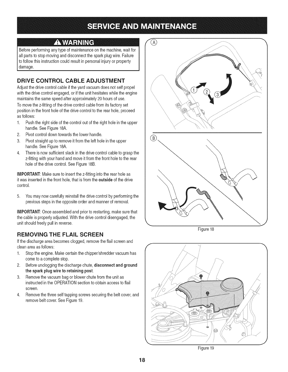
DRIVE CONTROL CABLE ADJUSTMENT
Adjustthe drivecontrolcableif the yardvacuumdoesnot selfpropel
withthedrive controlengaged,or if theunit hesitateswhilethe engine
maintainsthe samespeedafterapproximately20hoursof use.
Tomovethe z-fittingof the drivecontrolcablefromits factoryset
positioninthe frontholeof the drivecontrolto the rearhole,proceed
as follows:
1. Pushthe rightside of thecontrolout of the rightholeinthe upper
handle.See Figure18A.
2. Pivotcontroldowntowardsthe lowerhandle.
3. Pivotstraightupto removeit from the leftholein the upper
handle.See Figure18A.
4. Thereis nowsufficientslack inthe drivecontrolcableto graspthe
z-fittingwithyourhandand moveit fromthe frontholeto the rear
holeof the drivecontrol.See Figure18B.
IMPORTANT:Makesureto insertthe z-fittinginto the rearholeas
it wasinsertedin thefronthole,thatis fromthe outside of the drive
control.
5. Youmaynowcarefullyreinstallthe drivecontrolby performingthe
previousstepsinthe oppositeorderandmannerof removal.
IMPORTANT:Onceassembledand priorto restarting,makesurethat
thecable is properlyadjusted.Withthedrive controldisengaged,the
unit shouldfreelypullin reverse.
REMOVING THE FLAIL SCREEN
Ifthe dischargeareabecomesclogged,removetheflail screenand
cleanareaas follows:
1. Stopthe engine.Makecertainthe chipper/shreddervacuumhas
cometo a completestop.
2. Beforeuncloggingthe dischargechute,disconnect and ground
the spark plugwire to retaining post.
3. Removethe vacuumbagor blowerchutefromthe unitas
instructedin the OPERATIONsectionto obtainaccessto flail
screen.
4. Removethe three selftappingscrewssecuringthebelt cover,and
removebeltcover.SeeFigure19.
f
\
Figure18
/...... j
iJ'
/
/// _i
Figure19
J
18
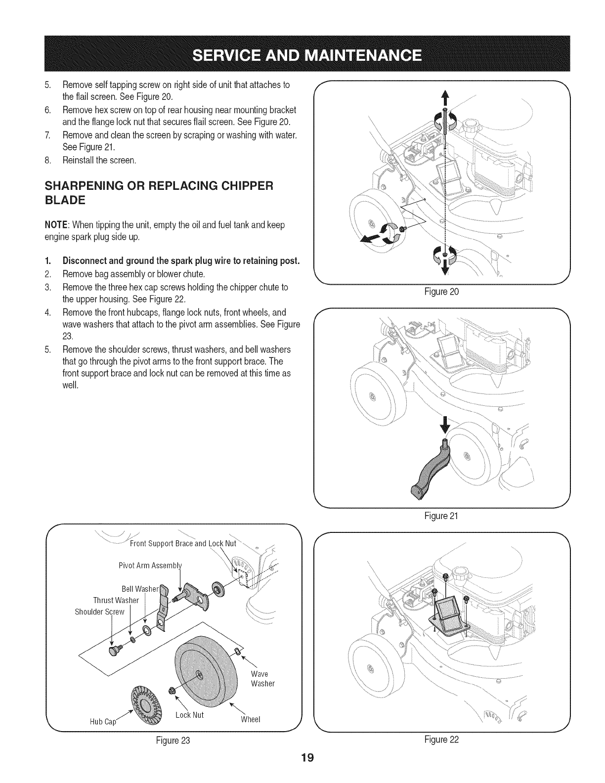
5. Removeselftappingscrewon rightsideof unitthatattachesto
the flailscreen.SeeFigure20.
6. Removehexscrewontop of rearhousingnearmountingbracket
andthe flangelocknutthatsecuresflail screen.SeeFigure20.
7. Removeandcleanthe screenby scrapingorwashingwithwater.
SeeFigure21.
8. Reinstallthe screen.
SHARPENING OR REPLACING CHIPPER
BLADE
NOTE:Whentippingthe unit,emptythe oil andfuel tankandkeep
enginesparkplugsideup.
1. Disconnectand groundthe spark plugwire to retainingpost.
2. Removebagassemblyor blowerchute.
3. Removethethree hexcap screwsholdingthe chipperchuteto
the upperhousing.SeeFigure22.
4. Removethefronthubcaps,flangelocknuts,frontwheels,and
wavewashersthatattachto the pivotarm assemblies.SeeFigure
23.
5. Removetheshoulderscrews,thrustwashers,andbellwashers
thatgothroughthe pivotarmsto the frontsupportbrace.The
frontsupportbraceandlocknutcan beremovedat thistimeas
well.
............................Front support Brace and Lock Nut
BellWasher
ThrustWasher
ShoulderScrew
Hub Cap_ Lock Nut
Wave
Washer
Figure23
J
f
Figure20
J
Figure21
jl j¸ ,
J
Figure22
J
19
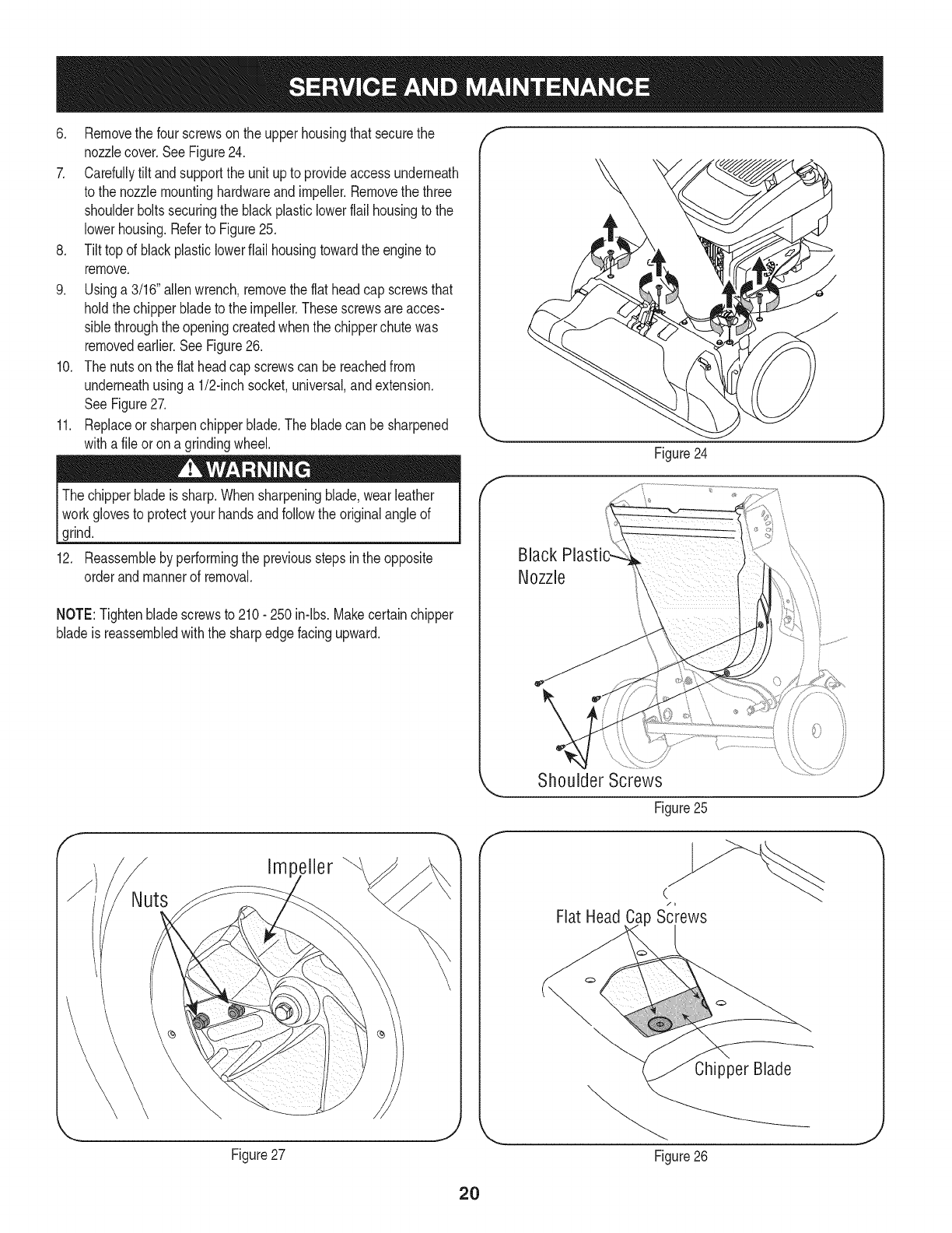
6. Removethe four screwson the upperhousingthat securethe
nozzlecover,SeeFigure24.
7. Carefullytilt andsupportthe unit upto provideaccessunderneath
to the nozzlemountinghardwareand impeller.Removethe three
shoulderboltssecuringthe blackplasticlowerflail housingto the
lowerhousing.Referto Figure25,
8. Tilttop of blackplasticlowerflail housingtowardthe engineto
remove.
9. Usinga 3/16"allenwrench,removetheflat headcap screwsthat
holdthechipperbladeto the impeller.Thesescrewsare acces-
siblethroughthe openingcreatedwhenthe chipperchutewas
removedearlier.SeeFigure26.
10. The nutson theflat headcap screwscan bereachedfrom
underneathusinga 1/2-inchsocket,universal,andextension.
SeeFigure27.
11. Replaceor sharpenchipperblade.The bladecanbe sharpened
witha fileor ona grindingwheel.
Thechipperbladeis sharp.Whensharpeningblade,wearleather
workglovesto protectyourhandsandfollowthe originalangleof
grind.
12. Reassembleby performingthe previousstepsin theopposite
orderand mannerof removal.
NOTE:Tightenbladescrewsto 210- 250 in-lbs.Makecertainchipper
bladeis reassembledwiththe sharpedgefacingupward.
f
Impeller
Figure27
f
Figure24
J
Black
Nozzle
f
Shoulder Screws
Figure25
J
(/i
Flat Head Ca Screws
Chipper Blade
Figure26
J
20
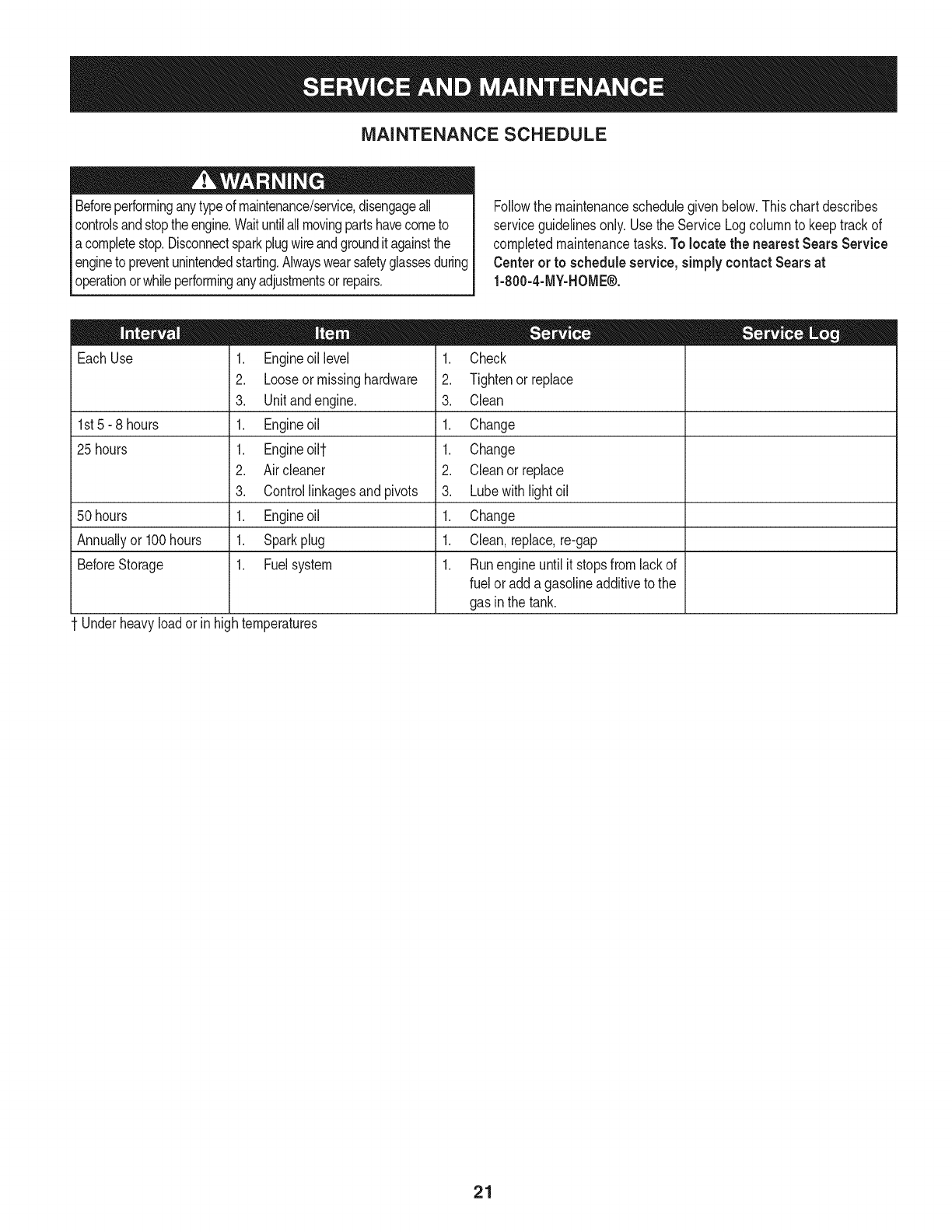
MAINTENANCE SCHEDULE
Beforeperforminganytypeof maintenance/service,disengageall
controlsandstoptheengine.Waituntilallmovingpartshavecometo
acompletestop.Disconnectsparkplugwireandgrounditagainstthe
engineto preventunintendedstarting.Alwayswearsafetyglassesduring
operationorwhileperforminganyadjustmentsor repairs.
Followthe maintenanceschedulegivenbelow.Thischartdescribes
serviceguidelinesonly.Usethe ServiceLogcolumnto keeptrackof
completedmaintenancetasks.To locate the nearest Sears Service
Centeror to scheduleservice,simplycontactSears at
1-800-4-MY-HOME®.
EachUse
1st5- 8 hours
25 hours
50 hours
Annuallyor 100hours
BeforeStorage
1 Underheavyloador inhightemperatures
1. Engineoil level
2. Looseor missinghardware
3. Unitandengine.
1. Engineoil
1. Engineoilt
2. Aircleaner
3. Controllinkagesand pivots
1. Engineoil
1. Sparkplug
1. Fuelsystem
= =
1. Check
2. Tightenor replace
3. Clean
1. Change
1. Change
2. Cleanor replace
3. Lubewithlightoil
1. Change
1. Clean,replace,re-gap
1. Runengineuntil it stopsfrom lackof
fuel or addagasolineadditiveto the
gas in the tank.
21
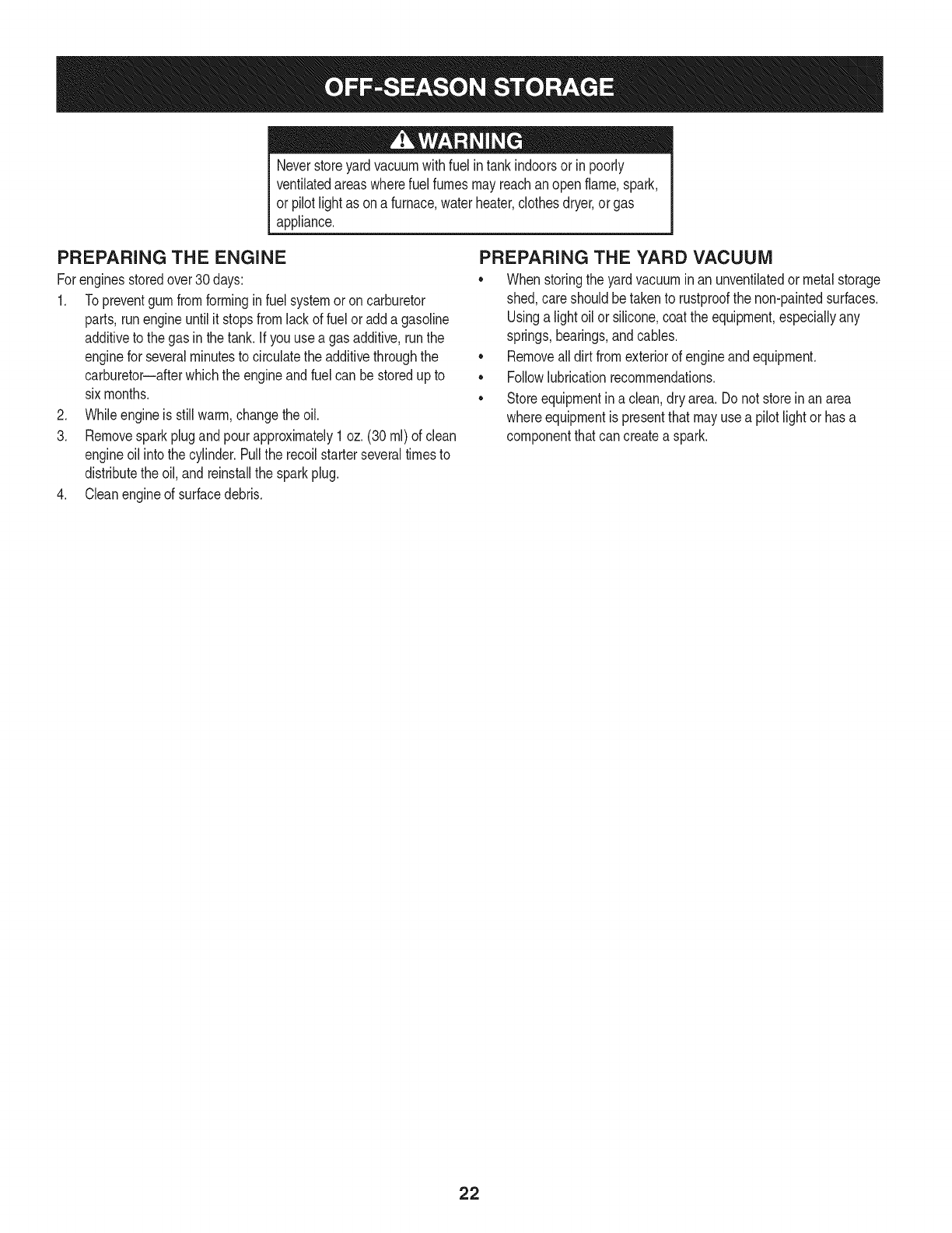
Neverstoreyardvacuumwithfuel intankindoorsor inpoorly
ventilatedareaswherefuel fumesmayreachanopenflame,spark,
or pilotlight as ona furnace,waterheater,clothesdryer,or gas
appliance.
PREPARING THE ENGINE
Forenginesstoredover30 days:
1. To preventgumfromforminginfuel systemor oncarburetor
parts, runengineuntilit stopsfromlackof fuelor adda gasoline
additiveto the gas inthe tank. Ifyou usea gas additive,runthe
enginefor severalminutesto circulatethe additivethroughthe
carburetor--afterwhichthe engineandfuel can bestoredup to
six months.
2. Whileengineis still warm,changethe oil.
3. Removesparkplugand pourapproximately1oz. (30rnl)of clean
engineoil intothe cylinder.Pullthe recoilstarterseveraltimesto
distributethe oil, andreinstallthe sparkplug.
4. Cleanengineof surfacedebris.
PREPARING THE YARD VACUUM
•Whenstoringthe yardvacuumin an unventilatedor metalstorage
shed,careshouldbetakento rustproofthe non-paintedsurfaces.
Usinga lightoil orsilicone,coatthe equipment,especiallyany
springs,bearings,andcables.
• Removealldirt fromexteriorof engineandequipment.
• Followlubricationrecommendations.
• Storeequipmentin a clean,dry area.Do not storein anarea
whereequipmentis presentthatmayusea pilot lightor hasa
componentthatcan createa spark.
22
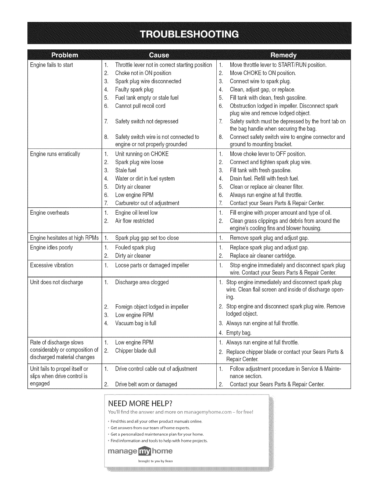
Enginefailsto start
Enginerunserratically
1. Throttlelevernot incorrectstartingposition
2. Chokenotin ON position
3. Sparkplugwire disconnected
4. Faultysparkplug
5. Fueltankemptyorstalefuel
6. Cannotpullrecoilcord
7. Safetyswitchnotdepressed
Engineoverheats
Enginehesitatesat high RPMs 1. Sparkpluggap settooclose
Engineidlespoorly 1. Fouledsparkplug
2. Dirtyair cleaner
Excessivevibration 1. Loosepartsor damagedimpeller
Unitdoesnot discharge 1. Dischargeareaclogged
Rateof dischargeslows
considerablyor compositionof
dischargedmaterialchanges
Unitfailsto propelitselfor
slipswhendrivecontrolis
engaged
8. Safetyswitchwireis not connectedto
engineor notproperlygrounded
1. Unitrunningon CHOKE
2. Sparkplugwire loose
3. Stalefuel
4. Wateror dirt in fuel system
5. Dirtyair cleaner
6. Lowengine RPM
7. Carburetorout of adjustment
1. Engineoil levellow
2. Airflowrestricted
2. Foreignobjectlodgedin impeller
3. Lowengine RPM
4. Vacuumbagis full
1. Lowengine RPM
2. Chipperbladedull
1. Drivecontrolcableout of adjustment
2. Drivebelt wornordamaged
1. Movethrottleleverto START/RUNposition.
2. MoveCHOKEto ONposition.
3. Connectwireto sparkplug.
4. Clean,adjustgap,or replace.
5. Filltankwithclean,freshgasoline.
6. Obstructionlodgedin impeller.Disconnectspark
plugwireandremovelodgedobject.
7. Safetyswitchmustbedepressedby the fronttab on
thebag handlewhen securingthe bag.
8. Connectsafetyswitchwire to engineconnectorand
groundto mountingbracket.
1. Movechokeleverto OFFposition.
2. Connectandtightensparkplugwire.
3. Filltankwithfreshgasoline.
4. Drainfuel.Refillwithfreshfuel.
5. Cleanor replaceair cleanerfilter.
6. Alwaysrunengineat full throttle.
7. ContactyourSearsParts& RepairCenter.
1. Fillenginewith properamountandtype of oil.
2. Cleangrassclippingsanddebrisfromaroundthe
engine'scoolingfinsandblowerhousing.
1. Removesparkplugandadjustgap.
1. Replacesparkplugandadjustgap.
2. Replaceair cleanercartridge.
1. Stopengineimmediatelyanddisconnectsparkplug
wire.ContactyourSearsParts& RepairCenter.
1. Stopengineimmediatelyanddisconnectsparkplug
wire.Cleanflail screenandinsideof dischargeopen-
ing.
2. Stopengineanddisconnectsparkplugwire.Remove
lodgedobject.
3. Alwaysrunengineat full throttle.
4. Emptybag.
1. Alwaysrunengineat full throttle.
2. Replacechipperbladeor contactyourSearsParts&
RepairCenter.
1. Followadjustmentprocedurein Service& Mainte-
nancesection.
2. ContactyourSearsParts& RepairCenter.
NEED MORE HELP?
You'II find t__e ed_swerr ,s]w:/more o[] m4r_4!jemyl]ome corn - k_r Iree
Find this and all your other product manuals online.
Get answers from our team of home experts.
Get a personalized maintenance plan for your home.
Find information and tools to help with home projects.
ma_age _ home
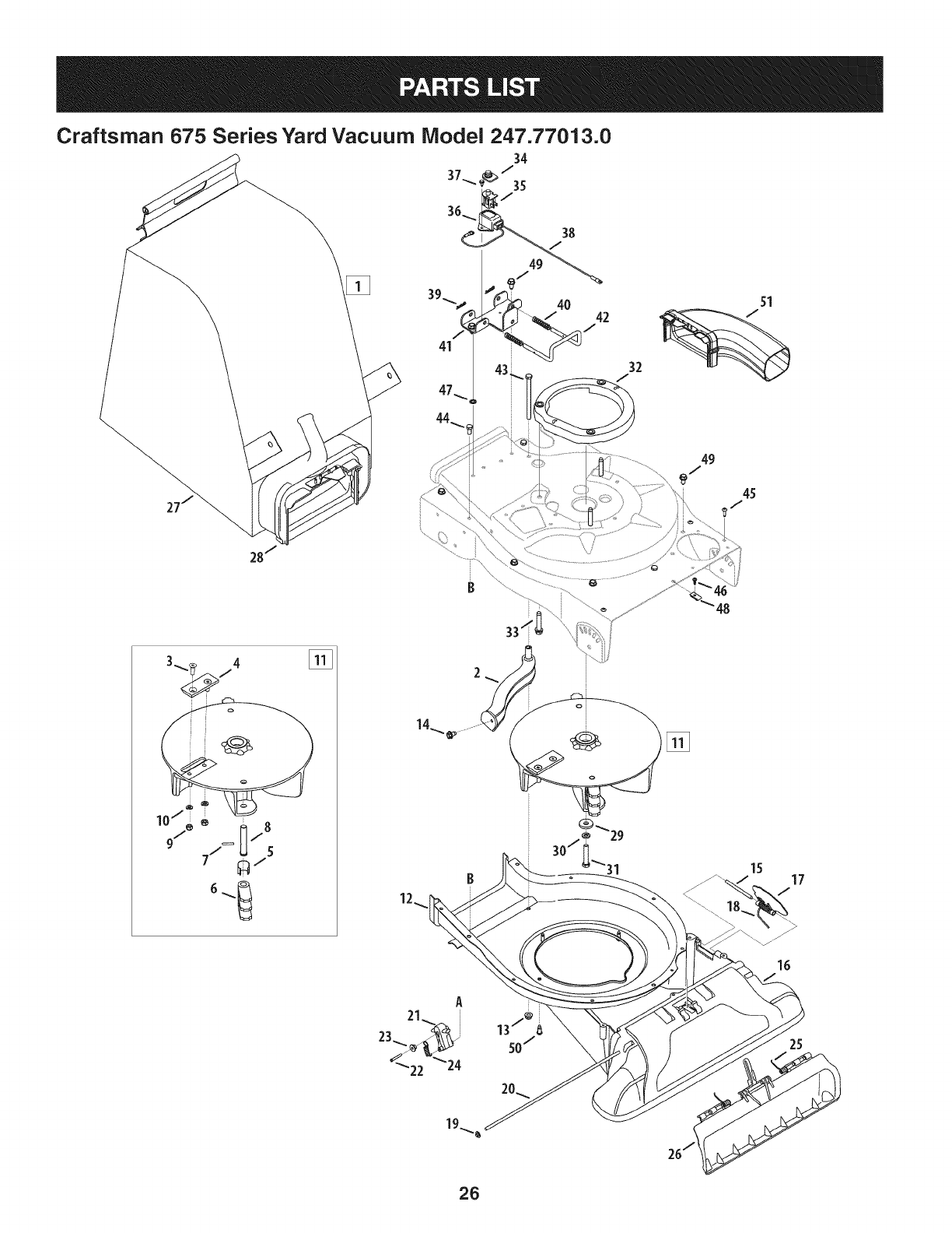
Craftsman 675 Series Yard Vacuum Model 247.77013.0
14
39
24
28
27
25
/
I0
A
32
34
53
35 37
/
23
58
59 57
24
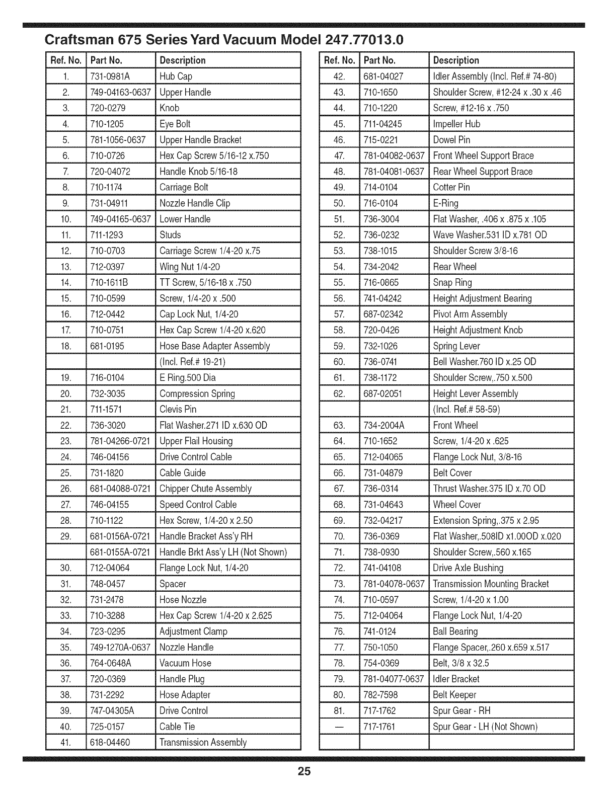
Craftsman 675 Series Yard Vacuum iVlodel 247.77013.0
Ref. No. Part No. Description
1. 731-0981A HubCap
2. 749-04163-0637 UpperHandle
3. 720-0279 Knob
4. 710-1205 EyeBolt
5. 781-1056-0637 UpperHandleBracket
6. 710-0726 HexCapScrew5/16-12x.750
7. 720-04072 HandleKnob5/16-18
8. 710-1174 CarriageBolt
9. 731-04911 NozzleHandleClip
10. 749-04165-0637 LowerHandle
11. 711-1293 Studs
12. 710-0703 CarriageScrew1/4-20x.75
13. 712-0397 Wing Nut1/4-20
14. 710-1611B TT Screw,5/16-18x .750
15. 710-0599 Screw,1/4-20x .500
16. 712-0442 Cap LockNut,1/4-20
17. 710-0751 HexCapScrew1/4-20x.620
18. 681-0195 HoseBaseAdapterAssembly
(Incl. Ref.#19-21)
19. 716-0104 ERing.500Dia
20. 732-3035 CompressionSpring
21. 711-1571 ClevisPin
22. 736-3020 FiatWasher.271IDx.630OD
23. 781-04266-0721 UpperFlail Housing
24. 746-04156 DriveControlCable
25. 731-1820 CableGuide
26. 681-04088-0721 ChipperChuteAssembly
27. 746-04155 SpeedControlCable
28. 710-1122 HexScrew,1/4-20x 2.50
29. 681-0156A-0721 HandleBracketAss'yRH
681-0155A-0721 HandleBrktAss'yLH (NotShown)
30. 712-04064 FlangeLockNut,1/4-20
31. 748-0457 Spacer
32. 731-2478 HoseNozzle
33. 710-3288 HexCapScrew1/4-20x 2.625
34. 723-0295 AdjustmentClamp
35. 749-1270A-0637 NozzleHandle
36. 764-0648A VacuumHose
37. 720-0369 HandlePlug
38. 731-2292 HoseAdapter
39. 747-04305A DriveControl
40. 725-0157 CableTie
41. 618-04460 TransmissionAssembly
Ref.No. Part No. Description
42. 681-04027 IdlerAssembly(Incl. Ref.#74-80)
43. 710-1650 ShoulderScrew,#12-24x .30x.46
44. 710-1220 Screw,#12-16x .750
45. 711-04245 ImpellerHub
46. 715-0221 DowelPin
47. 781-04082-0637 FrontWheelSupportBrace
48. 781-04081-0637 RearWheelSupportBrace
49. 714-0104 CotterPin
50. 716-0104 E-Ring
51. 736-3004 FiatWasher,.406x.875x.105
52. 736-0232 WaveWasher.531IDx.781OD
53. 738-1015 ShoulderScrew3/8-16
54. 734-2042 RearWheel
55. 716-0865 SnapRing
56. 741-04242 HeightAdjustmentBearing
57. 687-02342 PivotArmAssembly
58. 720-0426 HeightAdjustmentKnob
59. 732-1026 SpringLever
60. 736-0741 BellWasher.760IDx.25OD
61. 738-1172 ShoulderScrew,.750x.500
62. 687-02051 HeightLeverAssembly
(Incl.Ref.#58-59)
63. 734-2004A FrontWheel
64. 710-1652 Screw,1/4-20x .625
65. 712-04065 FlangeLockNut,3/8-16
66. 731-04879 BeltCover
67. 736-0314 ThrustWasher.375IDx.70OD
68. 731-04643 WheelCover
69. 732-04217 ExtensionSpring,.375x 2.95
70. 736-0369 FiatWasher,.5081Dxl.0OODx.020
71. 738-0930 ShoulderScrew,.560x.165
72. 741-04108 DriveAxle Bushing
73. 781-04078-0637 TransmissionMountingBracket
74. 710-0597 Screw,1/4-20x 1.00
75. 712-04064 FlangeLockNut, 1/4-20
76. 741-0124 BallBearing
77. 750-1050 FlangeSpacer,.260x.659x.517
78. 754-0369 Belt,3/8 x 32.5
79. 781-04077-0637 IdlerBracket
80. 782-7598 BeltKeeper
81. 717-1762 SpurGear- RH
-- 717-1761 SpurGear- LH (NotShown)
25
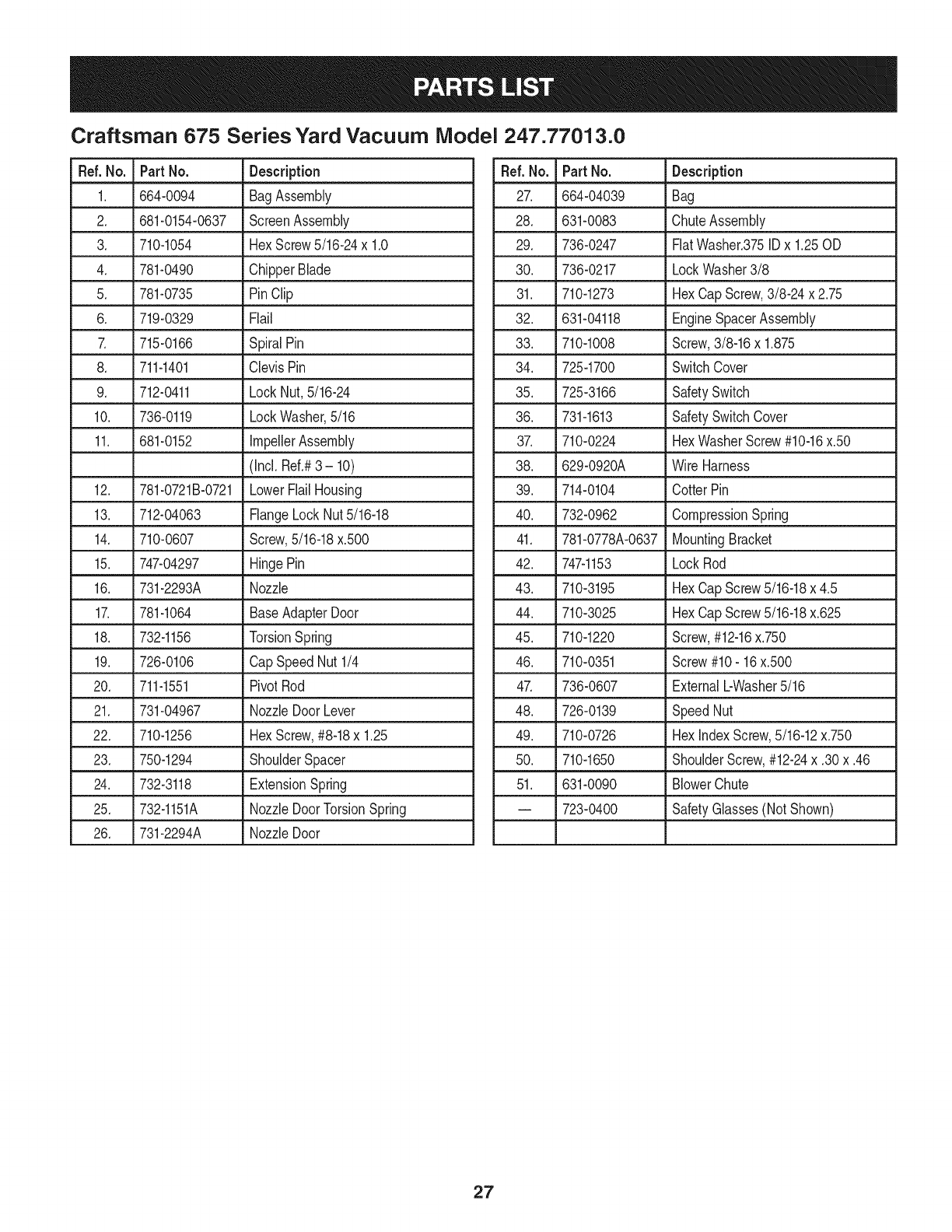
Craftsman 675 Series Yard Vacuum iVlodel 247.77013.0
49
@/
45
2
o
48
15 17
/
16
26
Craftsman 675 Series Yard Vacuum iVlodel 247.77013.0
Ref. No. Part No. Description
1. 664-0094 BagAssembly
2. 681-0154-0637 ScreenAssembly
3. 710-1054 HexScrew5/16-24x 1.0
4. 781-0490 ChipperBlade
5. 781-0735 PinClip
6. 719-0329 Flail
7. 715-0166 SpiralPin
8. 711-1401 ClevisPin
9. 712-0411 LockNut,5/16-24
10. 736-0119 LockWasher,5/16
11. 681-0152 impellerAssembly
(Incl. Ref.#3 - 10)
12. 781-0721B-0721 LowerFlailHousing
13. 712-04063 FlangeLockNut5/16-18
14. 710-0607 Screw,5/16-18x.500
15. 747-04297 HingePin
16. 731-2293A Nozzle
17. 781-1064 BaseAdapterDoor
18. 732-1156 TorsionSpring
19. 726-0106 CapSpeedNut1/4
20. 711-1551 PivotRod
21. 731-04967 NozzleDoorLever
22. 710-1256 HexScrew,#8-18x 1.25
23. 750-1294 ShoulderSpacer
24. 732-3118 ExtensionSpring
25. 732-1151A NozzleDoorTorsionSpring
26. 731-2294A NozzleDoor
Ref.No. Part No. Description
27. 664-04039 Bag
28. 631-0083 ChuteAssembly
29. 736-0247 FiatWasher.375IDx 1.25OD
30. 736-0217 LockWasher3/8
31. 710-1273 HexCap Screw,3/8-24 x 2.75
32. 631-04118 EngineSpacerAssembly
33. 710-1008 Screw,3/8-16x 1.875
34. 725-1700 SwitchCover
35. 725-3166 SafetySwitch
36. 731-1613 SafetySwitchCover
37. 710-0224 HexWasherScrew#10-16x.50
38. 629-0920A Wire Harness
39. 714-0104 CotterPin
40. 732-0962 CompressionSpring
41. 781-0778A-0637 MountingBracket
42. 747-1153 LockRod
43. 710-3195 HexCap Screw5/16-18x 4.5
44. 710-3025 HexCap Screw5/16-18x.625
45. 710-1220 Screw,#12-16x.750
46. 710-0351 Screw#10- 16x.500
47. 736-0607 ExternalbWasher5/16
48. 726-0139 SpeedNut
49. 710-0726 HexindexScrew,5/16-12x.750
50. 710-1650 ShoulderScrew,#12-24x .30x.46
51. 631-0090 BlowerChute
-- 723-0400 SafetyGlasses(NotShown)
27
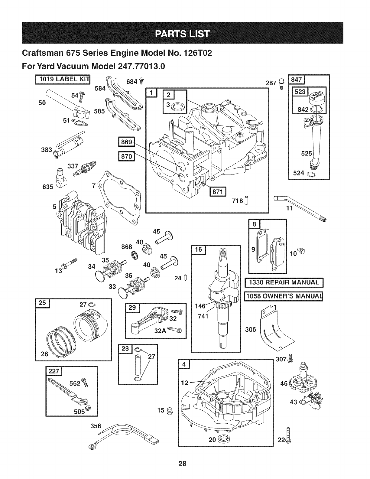
Craftsman 675 Series Engine Model No. 126T02
ForYard Vacuum Model 247.77013.0
j1019 LABEL KI'_
5O
383_'_
7(
635
287
718_
1330 REPAIR MANUAL ]
i1058 OWNER'S MANUA_
306
505@
28

Craftsman 675 Series Engine Model No. 126T02
For Yard Vacuum Model 247.77013.0
425
445 443_
843
81
613
977 CARBURETOR
GASKET SET
163_137_
7_ 633A @
633G
61 276_
365
121 CARBURETOR OVERHAUL KiT
633A@
163_
lo4%_
276 127
968
836 _ _;_ _._/
621_
966_ 159
._ 29_ 970
615
404
616__
633_
692 |
633A @
104
137(
276
276
163 _
127<3
130 95
633
0
617
29

Craftsman 675 Series Engine Model No. 126T02
ForYard Vacuum Model 247.77013.0
3_ 20
358 ENGINE GASKET SET
__329 REPLACEMENT ENGINE 1
921 '_\
%
78
930
I
601
1036 EMiSSiONS LABEL I
!
1005
m
45o
60
689 O
3O

Craftsman 675 Series Engine Model No. 126T02
For Yard Vacuum iVlodel 247.77013.0
D = "O
697322 CylinderAssembly
2. 399269 Kit-Bushing/Seal
3. 299819t Seal-Oil(MagnetoSide)
4. 493279 Sump-Engine
5. 691160 Head-Cylinder
7. 692249t Gasket-CylinderHead
8. 695250 BreatherAssembly
9. 699472 Gasket-Breather
10. 691125 Screw(BreatherAssembly)
11. 691260 Tube-Breather
12. 692232t Gasket-Crankcase
13. 690912 Screw(CylinderHead)
15. 691680 Plug-OilDrain
16. 694478 Crankshaft
20. 399781t Seal-Oil(PTOSide)
22. 691092 Screw(EngineSump)
23. 692315 Flywheel
24. 222698 Key-Flywheel
25. 697339 PistonAssembly(Standard)
697341 PistonAssembly(.020"Oversize)
26. 499425 RingSet-Piston(Standard)
499427 RingSet-Piston(.020"Oversize)
27. 691866 Lock-PistonPin
28. 499423 Pin-Piston
29. 499424 Rod-Connecting
32. 691664 Screw(ConnectingRod)
32A. 695759 Screw(ConnectingRod)
33. 262651 Valve-Exhaust
34. 262652 Valve-Intake
D = O Q
691270 Spring-Valve(Intake)
36. 691270 Spring-Valve(Exhaust)
37. 694086 Guard-Flywheel
40. 692194 Retainer-Valve
43. 691997 Slinger-Governor/Oil
45. 690548 Tappet-Valve
46. 691449 Camshaft
48. 498828 Short Block
50. 497465 Manifold-Intake
51. 272199t Gasket-intake
54. 691650 Screw(IntakeManifold)
55. 691421 Housing-RewindStarter
58. 697316 Rope-Starter(Cutto RequiredLength)
60. 281434 Grip-StarterRope
65. 690837 Screw(RewindStarter)
78. 691108 Screw(FlywheelGuard)
81. 691740 Lock-MufflerScrew
95. 691636 Screw(ThrottleValve)
97. 493267 Shaft-Throttle
104. 691242tt Pin-FloatHinge
108. 691182 Valve-Choke
109. 498593 Shaft-Choke
117. 498978 Jet-Main(Standard)
121. 498260 Kit-CarburetorOverhaul
125. 499059 Carburetor
127. 694468tt Plug-Welch
130. 691203 Valve-Throttle
133. 398187 Float-Carburetor
134. 398188tt Valve-Needle/Seat
31

Craftsman 675 Series Engine Model No. 126T02
ForYard Vacuum Model 247.77013.0
D = O
693981tt* Gasket-FloatBowl
146. 690979 Key-Timing
159. 691753 Bracket-AirCleanerPrimer
163. 272653t*tt Gasket-AirCleaner
187. 691050 Line-Fuel(Cutto RequiredLength)
188. 693399 Screw(ControlBracket)
190. 690940 Screw(FuelTank)
202. 691829 Link-MechanicalGovernor
209. 691291 Spring-Governor
222. 692150 Bracket-Control
227. 690783 ControlLever-Governor
276. 271716tt* SealingWasher
287. 690940 Screw(DipstickTube)
300. 692038 Muffler
304. 493294 Housing-Blower
305. 691108 Screw(BlowerHousing)
306. 690450 Shield-Cylinder
307. 690345 Screw(CylinderShield)
324. 695161 Cup/ScreenAssembly
332. 690662 Nut(Flywheel)
333. 802574 Armature-Magneto
334. 691061 Screw(ArmatureMagneto)
337. 802592 Plug-Spark
347. 691396 Switch-Rocker
Ref.No. PartNo. Description
356. 496381 Wire-Stop
358. 497316 EngineGasketSet
D = O
19069 FlywheelPuller
365. 692524 Screw(Carburetor)
383. 89838 Wrench-SparkPlug
404. 690272 Washer(GovernorCrank)
425. 690670 Screw(AirCleanerCover)
443. 692523 Screw(AirCleanerPrimerBase)
445. 491588 Filter-AirCleanerCartridge
456. 692299 Plate-PawlFriction
459. 281505 PawI-Ratchet
497. 690664 Screw(Stopswitch)
505. 691251 Nut(GovernorControlLever)
523. 495264 Dipstick
524. 692296t Seal-DipstickTube
525. 495265 Tube-Dipstick
529. 691923 Grommet
562. 92613 Bolt(GovernorControlLever)
564. 698589 Screw(ControlCover)
584. 697734 Cover-BreatherPassage
585. 691879t Gasket-BreatherPassage
592. 690800 Nut(RewindStarter)
597. 691696 Screw(PawlFrictionPlate)
601. 95162 Clamp-Hose
604. 698588 Cover-Control
608. 497680 Starter-Rewind
613. 691340 Screw(Muffler)
615. 690340 Retainer-GovernorShaft
616. 698801 Crank-Governor
32
Craftsman 675 Series Engine Model No. 126T02
For Yard Vacuum iVlodel 247.77013.0
270344t*tt
621. 692310
62Z 692872
633. 691321ff*
633A. 693867ff*
D = I! It
Seal-ORing(IntakeManifold)
Switch-Stop
Bracket-Stopswitch
Seal-Choke/ThrottleShaft
Seal-Choke/ThrottleShaft
635. 66538 Boot-Spark Plug
668. 493823 Spacer
670. 692294 SpacepFueITank
Ref.No. PartNo. Description
684. 690345 Screw(BreatherPassageCover)
689. 691855 Spring-Friction
692. 690579 Spring-Detent
718. 690959 Pin-Locating
741. 790345 Gear-Timing
832. 499034 Guard-Muffler
836. 690664 Screw(MufflerGuard)
842. 6910311- Seal-ORing (DipstickTube)
843. 691884 Sleeve-Lever
847. 692017 Assembly-Dipstick/Tube
851. 493880 Terminal-SparkPlug
868. 697338 Seal-Valve
869. 691155 Seat-Valve(intake)
870. 690380 Seat-Valve(Exhaust)
m = I! O
262001 Bushing-Guide(Exhaust)
63709 Bushing-Guide(Intake)
921. 698587 Cover-BlowerHousing
930. 691919 Guard-Rewind
957. 397974 Cap-FuelTank
966. 496116 Base-AirCleanerPrimer
968. 692298 Cover-AirCleaner
969. 690700 Screw(BlowerHousingCover)
970. 691669 Screw(Air CleanerPrimerBracket)
972. 699374 Tank-Fuel
975. 493640 Bowl-Float
976. 694395 Primer-Carburetor
977. 498261 Set-CarburetorGasket
1005. 691346 Fan-Flywheel
1019. 494256 Kit-Label
1036. 697457 Label-Emission
1058. MS 5244 Owner'sManual
1059. 692311 Kit-Screw/Washer
1210. 498144 Assembly-Pulley/Spring(Pulley)
1211. 498144 Assembly-Pulley/Spring(Spring)
1329. 123K02- ReplacementEngine
0240-E1
1330. 272147 RepairManual
tlncluded in EngineGasketSet,Key.No.358
ttlncluded inCarburetorOverhaulKit, Key.No.121
*includedin CarburetorGasketSet,Key.No.977
33
(Thispageapplicableinthe U.S.A.and Canadaonly.)
Sears, Roebuck and Co., U.S.A. (Sears), the California Air Resources Board (CARD)
and the United States Environmental Protection Agency (U.S. EPA)
Emission Control System Warranty Statement (Owner's Defect Warranty Rights and Obligations)
EMISSIONCONTROLWARRANTYCOVERAGEISAPPLICABLETOCERTI-
FIEDENGINESPURCHASEDINCALIFORNIAIN1995ANDTHEREAF-
TER,WHICHARE USEDINCALIFORNIA,ANDTOCERTIFIEDMODEL
California and United States Emission
The CaliforniaAir ResourcesBoard(CARD),U.S.EPAand Searsare pleased
to explainthe EmissionControlSystemWarrantyon your modelyear2000and
latersmalloff-roadengine(SORE).In California,newsmall off-roadengines
mustbedesigned,builtand equippedto meettheState'sstringentanti-smog
standards.Elsewherein theUnitedStates,newnon-road,spark-ignition
enginescertifiedfor modelyear 1997and latermustmeetsimilarstandardsset
forthbythe U.S.EPA.Searsmustwarranttheemissioncontrolsystemon your
YEAR1997ANDLATERENGINESWHICHARE PURCHASEDAND USED
ELSEWHEREINTHEUNITEDSTATES(ANDAFTERJANUARY1,2001 IN
CANADA).
Control Defects Warranty Statement
enginefor theperiodsoftime listedbelow,providedtherehasbeen noabuse,
neglector impropermaintenanceof your smalloff-roadengine.Youremis-
sion controlsystemincludespartssuch as thecarburetor,air cleaner,ignition
system,mufflerand catalyticconverter.Also includedmaybeconnectorsand
otheremissionrelatedassemblies.Wherea warrantableconditionexists,Sears
will repairyour smalloff-roadengineat no costto you includingdiagnosis,parts
and labor.
Sears Emission Control Defects Warranty Coverage
Smalloff-roadenginesarewarrantedrelativeto emissioncontrolpartsdefects
fora periodof one year,subjectto provisionsset forth below.Ifany covered
Owner's Warranty
Asthe smalloff-roadengineowner,you are responsiblefor theperformanceof
therequiredmaintenancelistedin yourOperatingand MaintenanceInstruc-
tions.Searsrecommendsthatyou retainallyourreceiptscoveringmaintenance
onyoursmalloff-roadengine,butSears cannotdenywarrantysolelyfor the
lackof receiptsor for yourfailureto ensuretheperformanceof allscheduled
maintenance.As the smalloff-roadengineowner,you shouldhoweverbe
awarethat Searsmaydenyyouwarrantycoverageifyour smalloff-roadengine
ora part hasfaileddueto abuse,neglect,impropermaintenanceor unap-
parton yourengineis defective,the partwillbe repairedorreplacedbySears.
Responsibilities
provedmodifications.Youare responsiblefor presentingyour smalloff-road
engineto anAuthorizedSearsServiceDealeras soonas a problemexists.The
undisputedwarrantyrepairsshouldbecompletedina reasonableamountof
time,notto exceed30 days.Ifyouhaveanyquestionsregardingyourwarranty
rightsand responsibilities,you shouldcontacta SearsService Representative
at 1--800--469--4663.The emissionwarrantyis a defectswarranty.Defectsare
judgedon normalengineperformance.Thewarrantyis notrelatedto an in-use
emissiontest.
Sears Emission Control Defects Warranty Provisions
ThefollowingarespecificprovisionsrelativetoyourEmissionControlDefectsWarrantyCoverage.ItisinadditiontotheSearsenginewarrantyfornon-regulated
enginesfoundin theOperatingand MaintenanceInstructions.
1. WarrantedParts
Coverageunderthis warrantyextendsonly to the parts listedbelow (the
emissioncontrolsystemsparts)to the extentthese partswere presenton
the enginepurchased.
a. FuelMeteringSystem
• Cold start enrichmentsystem
• Carburetorand internalparts
• FuelPump
b. AirlnductionSystem
• Aircleaner
• Intakemanifold
c. IgnitionSystem
• Sparkplug(s)
• Magnetoignitionsystem
d. CatalystSystem
• Catalyticconverter
• Exhaustmanifold
• Air injectionsystemor pulsevalve
e. MiscellaneousItemsUsedin AboveSystems
• Vacuum,temperature,position,timesensitivevalves
andswitches
• Connectorsandassemblies
2. Lengthof Coverage
Searswarrantsto the initialownerand eachsubsequentpurchaserthat
the WarrantedParts shallbe free fromdefects in materialsandworkman-
shipwhich causedthefailure of the WarrantedPartsfor a periodof one
yearfromthe datethe engineis deliveredto a retailpurchaser.
3. NoCharge
Repairor replacementof anyWarrantedPartwill beperformedat no
chargeto the owner,includingdiagnosticlabor whichleadsto the
determinationthata WarrantedPartis defective,ifthe diagnosticworkis
performedat an AuthorizedSears ServiceDealer.Foremissionswarranty
servicecontact yournearestAuthorizedSearsServiceDealeras listed in
the "YellowPages"under"Engines,Gasoline,""GasolineEngines,""Lawn
Mowers,"orsimilarcategory.
4. Claimsand CoverageExclusions
Warrantyclaimsshall be filed in accordancewiththe provisionsof the
SearsEngineWarrantyPolicy.Warrantycoverageshall beexcludedfor
failuresof WarrantedPartswhichare notoriginal Searspartsor because
of abuse,neglector impropermaintenanceas setforth inthe Sears
EngineWarrantyPolicy.Searsis notliableto coverfailuresof Warranted
Partscausedby theuseof add-on,non-original,or modifiedparts.
5. Maintenance
Any WarrantedPart whichis not scheduledfor replacementas required
maintenanceor whichis scheduledonly for regularinspectionto the effect
of "repairor replaceas necessary"shallbe warrantedasto defectsfor the
warrantyperiod.Any WarrantedPartwhich is scheduledfor replacement
as requiredmaintenanceshallbe warrantedasto defectsonly forthe
periodof time up to the first scheduledreplacementfor that part.Any
replacementpartthat is equivalentin performanceand durabilitymay
be usedin the performanceof any maintenanceor repairs.The owneris
responsibleforthe performanceof allrequiredmaintenance,as definedin
the SearsOperatingand MaintenanceInstructions.
6. ConsequentialCoverage
Coveragehereundershallextendto thefailure of anyenginecomponents
caused bythe failureof any WarrantedPartstill underwarranty.
Inthe USAandCanada,a 24 hourhotline, 1-800-469-4663,has a menuof pre-recordedmessagesofferingyou enginemaintenanceinformation.
34
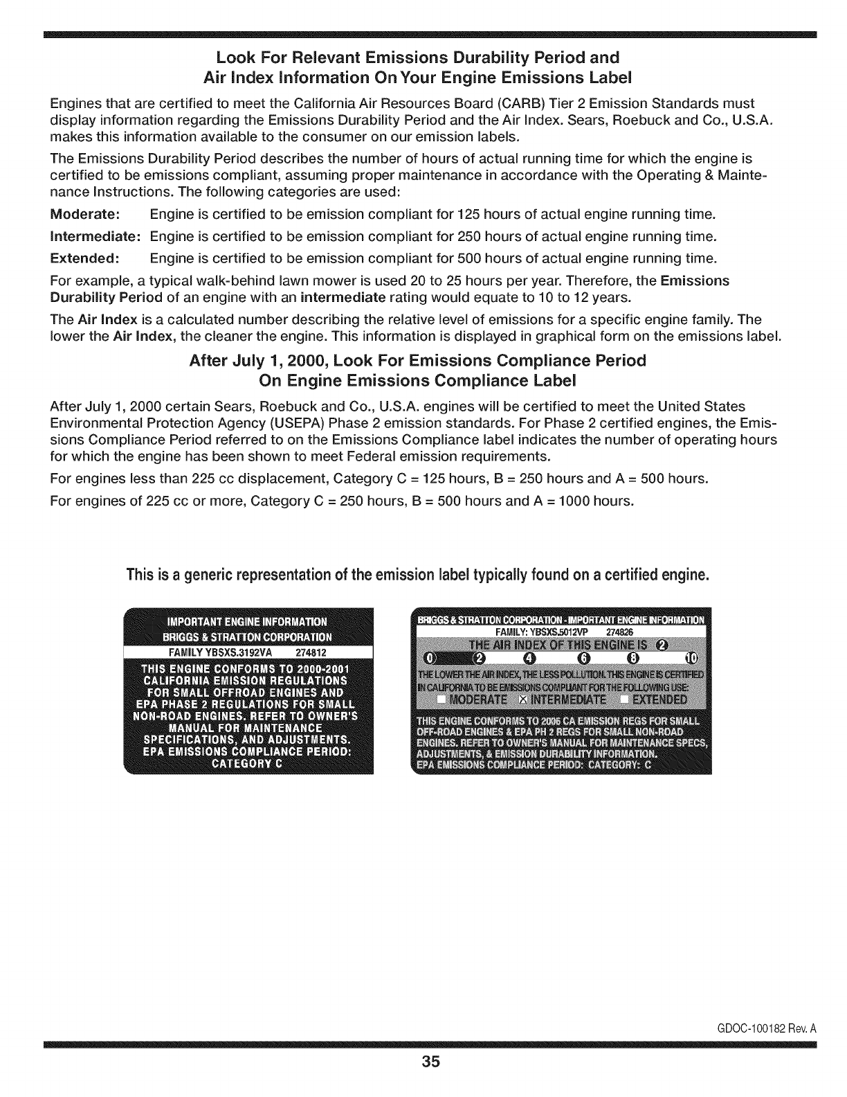
Look For Relevant Emissions Durability Period and
Air index information On Your Engine Emissions Label
Engines that are certified to meet the California Air Resources Board (CARB) Tier 2 Emission Standards must
display information regarding the Emissions Durability Period and the Air Index. Sears, Roebuck and Co., U.S.A.
makes this information available to the consumer on our emission labels.
The Emissions Durability Period describes the number of hours of actual running time for which the engine is
certified to be emissions compliant, assuming proper maintenance in accordance with the Operating & Mainte-
nance Instructions. The following categories are used:
Moderate: Engine is certified to be emission compliant for 125 hours of actual engine running time.
Intermediate: Engine is certified to be emission compliant for 250 hours of actual engine running time.
Extended: Engine is certified to be emission compliant for 500 hours of actual engine running time.
For example, a typical walk-behind lawn mower is used 20 to 25 hours per year. Therefore, the Emissions
Durability Period of an engine with an intermediate rating would equate to 10 to 12 years.
The Air Index is a calculated number describing the relative level of emissions for a specific engine family. The
lower the Air Index, the cleaner the engine. This information is displayed in graphical form on the emissions label.
After July 1,2000, Look For Emissions Compliance Period
On Engine Emissions Compliance Label
After July 1, 2000 certain Sears, Roebuck and Co., U.S.A. engines will be certified to meet the United States
Environmental Protection Agency (USEPA) Phase 2 emission standards. For Phase 2 certified engines, the Emis-
sions Compliance Period referred to on the Emissions Compliance label indicates the number of operating hours
for which the engine has been shown to meet Federal emission requirements.
For engines less than 225 cc displacement, Category C = 125 hours, B = 250 hours and A = 500 hours.
For engines of 225 cc or more, Category C = 250 hours, B = 500 hours and A = 1000 hours.
This is ageneric representation of the emission label typically found on a certified engine.
FAMILYYBSXS.3192VA 274812
GDOC-100182Rev.A
35
Congratulationson makinga smartpurchase.YournewCraftsman@
productis designedandmanufacturedfor yearsof dependableopera-
tion.But likeall products,it mayrequirerepairfromtimeto time.That's
whenhavinga RepairProtectionAgreementcansaveyoumoneyand
aggravation.
Here'swhat'sincludedin the Agreement:
• Expertserviceby our 12,000professionalrepairspecialists
• Unlimitedserviceandno chargefor partsandlaboronall covered
repairs
• Productreplacementif yourcoveredproductcan't befixed
• Discountof 10%fromregularpriceof serviceandservice-related
partsnotcoveredby theagreement;also,10%off regularpriceof
preventivemaintenancecheck
• Fasthelpby phone- phonesupportfroma Searstechnicianon
productsrequiringin-homerepair,plusconvenientrepair
scheduling
Purchasea RepairProtectionAgreementnowandprotectyourself
fromunexpectedhassleandexpense.
Onceyou purchasethe Agreement,a simplephonecall is all thatit
takesfor youto scheduleservice.Youcan call anytimedayor night,or
schedulea serviceappointmentonline.
Searshas over12,000professionalrepairspecialists,who have
accessto over4.5millionqualitypartsandaccessories.That'sthe
kindof professionalismyou can counton to helpprolongthe lifeof
your newpurchasefor yearsto come.Purchaseyour RepairProtection
Agreementtoday!
Somelimitations and exclusionsapply. For prices and additional
informationcall 1-800-827-6655.
Sears Installation Service
ForSearsprofessionalinstallationof homeappliances,garagedoor
openers,waterheaters,andothermajorhomeitems,in the U.S.A.call
1-800-4-MY-HOME®
36
Declaraci6n de garantia ....................... Pagina 36
Practicas operaci6n seguras ............... Paginas 38-41
Montaje ................................................ Paginas 42-45
Operaci6n ............................................ Paginas 46-49
Servicio y Mantenimiento .................... Paginas 50-55
Almacenamiento fuera de temporada .... Pagina 56
Soluci6n de problemas ...................... Pagina 57-58
Etiquetas de seguridad ....................... Pagina 7
Lista de piezas .......................................... Pagina 24
Acuerdo de Protecci6n Para
Reparaciones ....................................... Pagina 61
NOmero de servicio ..................... Cubierta posterior
Garantia completa de un a5o para la aspiradora para patios Craftsman
EsteequipoestAcubiertoporunagaranfiade unaSo,siemprequese mantenga,lubriquey ajustede acuerdocon las instruccionesdelpresente
manualdeloperador.Duranteel aSodegarantia,si esteequiposufrecualquierfallaproducidapordefectosenmaterialeso manode obra,
DEVUE_LVALOA SU CENTRODE PARTES& REPARACIONSEARSM_,SCERCANO,y SearsIo repararAsin ningQncargo.Elserviciode
garantiaa domiciiioestAdisponibieperose aplicarAuncargodetraslado.
Esta garantiano cubre:
• Arficulosde duraci6niimitadaquesufrendesgastebajocondicionesnormaiesde uso,talescomobujiasdeencendido,purificadoresde
aire,correasy fiitrosde aceite.
• Reemplazoo reparacionesde Ilantascausadasporpinchadurasconobjetosexteriorescomo,porejemplo,clavos,espinas,paloso vidrios,etc.
• Reparacionesnecesariasdebidoa abusodel operador,incluyendo,perosin limitarsea ellos,los daSoscausadosporobjetos,talescomo
piedras,desechosde metalo trozosdemaderade untamaSodemasiadogrande,objetosquehacenimpactoquepuedendoblarla
estructurao elcarter,o sobreaceierarei motor.
• Reparacionesnecesariasdebidoa negligenciadeloperador,incluyendoentre otros,daSosmecAnicoy eBctrico ocasionadoporun
almacenamientonoapropiado,falla porel usode aceitedegradoy/o cantidadnoapropiadao falla pornodarmantenimientoal equipode
acuerdocon las instruccionescontenidasenel manualdeloperador.
• Limpiezao reparacionesal motor(sistemadecombustible)provocadasporuncombustiblecontaminadouoxidado(viejo).Engeneral,ei
combustibledebeutilizarseen unperiodono mayorde 30dias a partirde su adquisici6n.
• Equiposutilizadosparafinescomercialesode alquiler.
Estagaranfias6iotendrAvalidezdurante90 dias si esteproductose utilizaen cualquiermomentoparafinescomerciaieso de aiquiier.
Estagaranfias6io tendrAvaiidezmientrasel productose utiiiceen los EstadosUnidos.
Estagaranfialeotorgaderechoslegalesespedficos,peroustedpodriagozarde otrosderechosen raz6nde su lugarde residencia.
Sears, Roebuck and Co., Hoffman Estates, iL 60179
Serie: 675
Tipodeaceitedelmotor: SAE30
Capacidadde aceitedel motor: 18onzas
Capacidadde combustible: 1 1/22 cuartos
Bujias: Champion®RJ19LM
Separaci6ndelas bujias: .020"
NSmerode modelo ..........................................................
N_mero de serie ..............................................................
Fechade compra .............................................................
Registrearribael nQmerodel modelo,el nQmerode seriey la fecha
de compra
©SearsBrands,LLC 37
Lapresenciadeestesfmboloindicaquesetratade
instruccionesimportantesdeseguridadquesedeben
respetarparaevitarponerenpeligrosuseguridad
personaly/omaterialyladeotraspersonas.Leay siga
todaslasinstruccionesdeestemanualantesdeponer
enfuncionamientoestam_quina.Sinorespetaestas
instruccionespodrfaprovocarlesionespersonales.Cuando
veaestesfmbolo,ipresteatenci6nalaadvertencia!
CALIFORNIA PROPOSITION 65
Engine Exhaust, some of its constituents, and certain vehicle
components contain or emit chemicals known to State
of California to cause cancer and birth defects or other
reproductive harm.
Esta m_quina rue construida para ser operada de acuerdo
con las reglas de seguridad contenidas en este manual.
AI igual que con cualquier tipo de equipo motorizado, un
descuido o error por parte del operador puede producir
lesiones graves. Esta m_quina es capaz de amputar manos y
pies y de arrojar objetos con gran fuerza. De no respetar las
instrucciones de seguridad siguientes se pueden producir
lesiones graves o la muerte.
Su responsabilidad--Restrinja el uso de esta m_quina
motorizada alas personas que lean, comprendan y respeten
las advertencias e instrucdones que aparecen en este
manual yen la m_quina.
iGUARDEESTASINSTRUCCIONES!
Capacitaci6n
1. Lea, entienda y cumpla todas las instrucciones incluidas en
la m_quina yen los manuales antes de montarla y utilizarla.
Guarde este manual en un lugar seguro para consultas futuras
y regulares, asi como para solicitar repuestos.
2. Familiaricese con todos los controles y su operaci6n adecuada.
Sepa c6mo detener la m_quina y c6mo desengranar los
controles r_pidamente.
3. No permita nunca que los niflos menores de 16 aflos utilicen
esta m_quina. Los niflos de 16 aflos y m_s mayores deben leer
y comprender las instrucciones de operaci6n y las reglas de
seguridad contenidas en este manual, y tambi6n deben ser
capacitados y estar supervisados pot uno de los padres.
4. Nunca permita que los adultos operen esta m_quina sin recibir
antes la instrucci6n apropiada.
5. Mantenga a los transeuntes, ayudantes, mascotas y niEos
al menos a 75 pies de la m_quina mientras est_ operando.
Detenga la m_quina si alguien entra en la zona.
6. Nunca encienda un motor en espacios cerrados o en una zona
con poca ventilaci6n. El escape del motor contiene mon6xido
de carbono, un gas inodoro y letal.
7. No ponga las manos o los pies cerca de las piezas rotatorias
o en las c_maras de alimentaci6n ni en la abertura de
descarga. El contacto con el motor rotatorio puede producir la
amputaci6n de dedos, manos o pies.
8. Nunca trate de destapar la toma de alimentaci6n o la abertura
de descarga, nitrate de sacar o vaciar la bolsa de la aspiradora,
ni de revisar y reparar la m_quina mientras el motor est_ en
marcha. Apague el motor y espere hasta que todas las piezas
m6viles se hayan detenido pot completo. Desconecte el cable
de la bujia y p6ngalo de manera que haga masa contra el
motor.
Preparativos
1. Inspeccione minuciosamente el _irea donde utilizar_i el equipo.
Retire todas las piedras, botellas, latas u otros objetos extraflos
que puedan ser levantados o arrojados causando lesiones
personales o daflos a la m_iquina.
2. Para protegerse los ojos utilice siempre anteojos o antiparras
de seguridad mientras opera la m_iquina o mientras la ajusta
o repara. Los objetos arrojados que rebotan pueden lesionar
gravemente la vista.
3. Utilice zapatos de trabajo resistentes, de suela fuerte, asi como
pantalones y camisas ajustados. Las prendas sueltas o las
alhajas pueden quedar atrapadas en las piezas mdviles. Nunca
utilice la m_iquina descalzo o con sandalias. Utilice guantes de
trabajo de cuero cuando alimente material por el canal de la
cortadora.
4.
5.
Antes de encender la m_iquina controle que todos los pernos y
tomillos est_n bien ajustados para comprobar que la m_iquina se
encuentra en condiciones seguras de operacidn. Adem_is, realice
una inspeccidn visual de la m_iquina a intervalos frecuentes para
controlar si la misma est,1 daflada.
Mantenga o reemplace las etiquetas de seguridad e
instrucciones segun sea necesario.
Manejosegurode ia gasolina
Para evitar lesiones personales o daflos materiales sea sumamente
cuidadoso al manipular la gasolina. La gasolina es altamente
inflamable y sus vapores pueden causar explosiones. Se puede
lesionar gravemente si derrama gasolina sobre usted o sobre la ropa
ya que se puede encender. L_vese la piel y c_mbiese de ropa de
inmediato.
1. Utilice s61o recipientes para gasolina autorizados.
38
2.
3.
4.
5.
6.
Z
Nunca Ilene los contenedores en el interior de un vehiculo
o cami6n o caja de camioneta con recubrimientos pl_isticos.
Coloque siempre los recipientes en el piso y lejos del vehiculo
antes de Ilenarlos.
Retire el equipo a gasolina del cami6n o remolque y II_nelo en
el piso. Si esto no es posible, entonces Ilene dicho equipo en
un remolque con un recipiente port_itil, en vez de desde un
dispensador de gasolina.
Mantenga la boquilla de Ilenado en contacto con el borde
de la entrada del tanque de gasolina o contenedor en todo
momento hasta que est_ Ileno. No utilice un dispositivo para
abrir/cerrar la boquilla.
Apague todos los cigarrillos, cigarros, pipas y otras fuentes de
combusti6n.
Nunca cargue combustible en la m_iquina en un espacio
cerrado.
Nunca saque la tapa del gas ni agregue combustible mientras
el motor est,1 caliente o en marcha. Deje que el motor se
enfrie por Io menos dos minutos antes de volver a cargar
combustible.
8. Nunca recargue el tanque de combustible. Llene el tanque no
m_fisde 1/2 pulgada pot debajo de la base del cuello del filtro
para dejar espacio para la dilataci6n del combustible.
9. Vuelva a colocar la tapa de la gasolina y ajustela bien.
10. Limpie la gasolina derramada sobre el motor y el equipo.
Traslade la m_iquina a otra zona. Espere 5 minutos antes de
encender el motor.
11. Nunca almacene la m_fiquina o el recipiente de combustible en
un espacio cerrado donde haya fuego, chispas o luz piloto (pot
ejemplo, hornos, calentadores de agua, calefactores, secadores
de ropa, etc.)
12. Para reducir el riesgo de incendio mantenga la m_iquina limpia
de pasto, hojas y de acumulaci6n de otros desechos. Limpie los
derrames de aceite o combustible y saque todos los desechos
embebidos con combustible.
Operad6n
1. No ponga las manos o los pies cerca de las piezas rotatorias
o en las c_imaras de alimentaci6n ni en la abertura de
descarga. El contacto con el motor rotatorio puede producir la
amputaci6n de dedos, manos o pies.
2. Antes de encender la m_iquina compruebe que el canal de la
cortadora, la toma de alimentaci6n y la c_imara de corte est_in
vacias y sin desechos.
3. Inspeccione minuciosamente todo el material que desea
triturar y saque los objetos met_ilicos, piedras, botellas, latas u
otros objetos extraflos que pueden ocasionar lesiones o daflar
la m_iquina.
4. Si el motor golpea un objeto extraflo o si la m_iquina empieza
a producir un sonido poco comun o una vibraci6n, apague
el motor de inmediato. Deje que el motor se detenga pot
completo. Desconecte el cable de la bujia, p6ngalo de manera
que haga masa contra el motor y siga estos pasos:
a. Inspeccione la m_fiquina para vet si est,1 daflada.
b. Repare o reemplace las piezas dafladas.
c. Controle si hay piezas flojas y ajustelas para asegurar
que la m_iquina funcione de manera segura y continua.
5. No permita que se acumule material procesado en la zona de
descarga. El mismo puede obstaculizar la descarga adecuada
y provocar el retorno del material a trav_s de la abertura de
alimentaci6n.
No intente triturar ni picar material de mayor tamaflo al
especificado en la m_iquina o en este manual. Se podrian
producir lesiones o daflos.
Nunca trate de destapar la toma de alimentaci6n o la abertura
de descarga mientras el motor est,1 en marcha. Apague el
motor y espere hasta que todas las piezas que se mueven se
hayan detenido pot completo, desconecte el cable de la bujia
y p6ngalo de manera que haga masa contra el motor antes de
sacar los escombros.
8. Nunca opere la m_iquina sin que la bolsa de la aspiradora y
el canal de descarga est6n conectados a la m_iquina como
corresponde. Nunca vacie ni cambie la bolsa de la aspiradora
mientras el motor est,1 en marcha. El extremo con cierre de la
bolsa de la aspiradora debe quedar cerrado todo el tiempo
mientras la opera.
9. Nunca opere la m_iquina si el pico de ingreso o la uni6n
opcional para la manguera no est_in conectados a la m_iquina
adecuadamente. Nunca intente conectar o cambiar ninguna
de estas uniones mientras el motor est,1 en marcha.
10. Mantenga todos los protectores, desviadores y dispositivos de
seguridad en su lugary en buenas condiciones.
11. Mientras alimenta material dentro de la m_iquina mantenga
su rostro y su cuerpo detr_is y hacia un costado del canal de la
cortadora para evitar lesiones por retrocesos accidentales.
12. Nunca opere esta m_iquina sin buena visibilidad o iluminaci6n.
Siempre debe estar seguro de que est,1 bien afirmado y
sostenga bien las manijas.
13. No opere esta m_iquina en superficies con grava.
14. No opere esta m_iquina estando bajo los efectos del alcohol o
de drogas.
15. El silenciador y el motor se calientan y pueden producir
quemaduras. No los toque.
16. Nunca levante o transporte la m_iquina cuando el motor est,1
encendido.
17. Si se presentan situaciones que no est_in previstas en este
manual sea cuidadoso y use el sentido comOn. Marque para
contactar el departamento de atenci6n al cliente y obtener el
nombre de su distribuidor m_is cercano.
39
Mantenimiento y almacenamiento
Nunca manipule los dispositivos de seguridad de manera
imprudente. Controle peri6dicamente que funcionen de forma
adecuada.
2. Controle frecuentemente que todos los pernos y tornillos
est_n bien ajustados para comprobar que la m_iquina se
encuentra en condiciones seguras de funcionamiento.
Adem_is, realice una inspecci6n visual de la m_iquina para
controlar si la misma est,1 dahada y rep_irela de set necesario.
3. Antes de limpiar, reparar o inspeccionar la m_iquina, detenga
el motor y compruebe que el mismo y que todas las piezas
m6viles se hallan detenido. Desconecte el cable de la bujia y
p6ngalo de manera que haga masa contra el motor para evitar
que se encienda de manera accidental.
4. No cambie la configuraci6n del regulador del motor ni acelere
demasiado el mismo. El regulador controla la velocidad
m_ixima segura de operaci6n del motor.
5. Mantenga o reemplace las etiquetas de seguridad e
instrucciones segun sea necesario.
6. Siga las instrucciones de este manual para cargar, descargar,
transportar y almacenar de manera segura esta m_fiquina.
7. Nunca almacene la m_iquina o el recipiente de combustible
en un espacio cerrado donde haya fuego, chispas o luz piloto
como pot ejemplo, calentadores de agua, hornos, secadores
de ropa, etc.
8. Deje que la m_iquina se enfrie pot Io menos 5 minutos antes de
guardarla.
9. Consulte siempre el manual del operador para conocer las
instrucciones adecuadas para el almacenamiento fuera de
temporada.
10. Segun la Comisi6n de Seguridad de Productos para el
Consumidor de los Estados Unidos (CPSC) y la Agencia de
Protecci6n Ambiental de los Estados Unidos (EPA), este
producto tiene una vida util media de siete (7) a_os, 6 60 horas
de funcionamiento. AI finalizar la vida util media, adquiera
una m_fiquina nueva o haga inspeccionar anualmente _sta
pot un distribuidor de servicio autorizado para cerciorarse de
que todos los sistemas mec_inicos y de seguridad funcionan
correctamente y no tienen excesivo desgaste. Si no Io hace,
pueden producirse accidentes, lesiones o muerte
11. Si debe vaciar el tanque de combustible, h_igalo al aire libre.
12. Respete las normas referentes a la disposici6n correcta y las
reglamentaciones sobre gas, combustible, etc. para proteger el
medio ambiente.
Nomodifique el motor
Para evitar lesiones graves o la muerte, no modifique el motor bajo
ninguna circunstancia. Si cambia la configuraci6n del regulador
el motor puede descontrolarse y operar a velocidades inseguras.
Nunca cambie la configuraci6n de f_ibrica del regulador del motor.
Avisoreferidoa emisiones
Los motores que est_in certificados y cumplen con las regulaciones
de emisiones federales EPA y de California para SORE (Equipos
peque_os todo terreno) est_fin certificados para operar con gasolina
comun sin plomo y pueden incluir los siguientes sistemas de control
de emisiones: Modificaci6n de motor (EM) y catalizador de tres vias
(TWC) si est_in equipados de esa manera.
Guardachispas
Esta m_iquina est,1 equipada con un motor de combusti6n interna
y no debe ser utilizada en o cerca de un terreno agreste cubierto
pot bosque, malezas o hierba excepto si el sistema de escape del
motor est,1 equipado con un amortiguador de chispas que cumpla
con las leyes locales o estatales correspondientes, en caso de
haberlas.
Si se utiliza un amortiguador de chispas el operador Io debe
mantener en condiciones de uso adecuadas. En el Estado de
California las medidas anteriormente mencionadas son exigidas pot
ley (Articulo 4442 del C6digo de Recursos Publicos de California).
Es posible que existan leyes similares en otros estados. Las leyes
federales se aplican en territorios federales.
Puede conseguir el amortiguador de chispas para el silenciador a
trav_s de su distribuidor autorizado de motores o poni_ndose en
contacto con el departamento de servicios.
4O
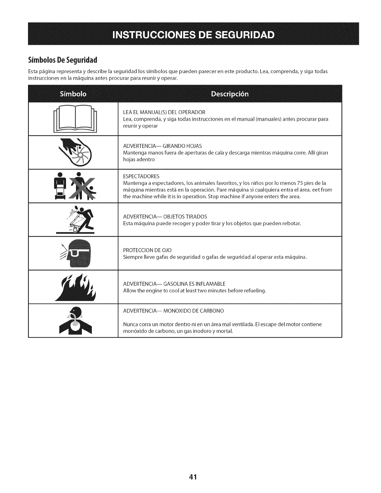
Sh'nbolosDeSeguridad
Esta p_igina representa y describe la seguridad los simbolos que pueden parecer en este producto. Lea, comprenda, y siga todas
instrucciones en la m_iquina antes procurar para reunir y operar.
A
• ®
llt
LEA EL MANUAL(S) DEL OPERADOR
Lea, comprenda, y siga todas instrucciones en el manual (manuales) antes procurar para
reuniry operar
ADVERTENClA-- GIRANDO HOJAS
Mantenga manos fuera de aperturas de cala y descarga mientras m_fiquina corre. Alli giran
hojas adentro
ESPECTADORES
Mantenga a espectadores, los animales favoritos, y los ni_os por Io menos 75 pies de la
m_iquina mientras est,1 en la operacidn. Pare m_iquina si cualquiera entra el _irea. eet from
the machine while it is in operation. Stop machine if anyone enters the area.
ADVERTENCIA-- OBJETOS TIRADOS
Esta m_iquina puede recoger y poder tirar y los objetos que pueden rebotar.
PROTECCION DE OJO
Siempre Ileve gafas de seguridad o gafas de seguridad al operar esta m_fiquina.
ADVERTENCIA-- GASOLINA ESINFLAMABLE
Allow the engine to cool at least two minutes before refueling.
ADVERTENCIA-- MONOXIDO DE CARBONO
Nunca corra un motor dentro ni en un _fireamal ventilada. El escape del motor contiene
mon6xido de carbono, un gas inodoro y mortal.
41
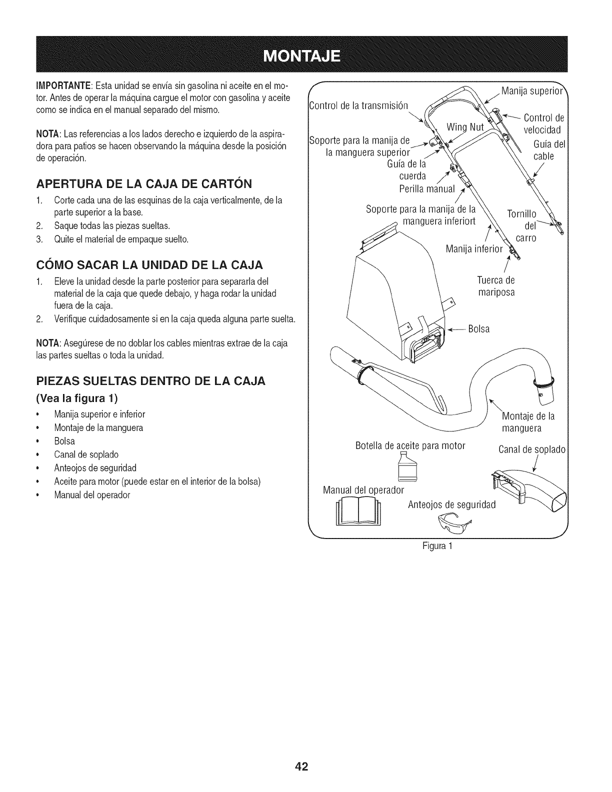
IMPORTANTE:Estaunidadse enviasin gasolinani aceiteenel mo-
tor.Antesdeoperarlarn_.quinacargueel motorcongasolinay aceite
cornose indicaen el manualseparadodelrnisrno,
NOTA:Lasreferenciasa los ladosderechoe izquierdodela aspira-
doraparapatiosse hacenobservandola rn_.quinadesdela posici6n
deoperaci6n.
APERTURA DE LA CAJA DE CARTON
1. Cortecada unade lasesquinasde la cajaverticalrnente,de la
partesuperiora la base.
2. Saquetodaslaspiezassueltas.
3. Quiteel materialdeernpaquesuelto.
COIVlO SACAR LA UNIDAD DE LA CAJA
1. Elevelaunidaddesdela parteposteriorparasepararladel
materialde la cajaquequededebajo,y hagarodarla unidad
fuerade lacaja.
2. Verifiquecuidadosarnentesi enla cajaquedaalgunapartesuelta.
NOTA:AsegOresede nodoblarloscablesrnientrasextraede lacaja
las partessueltaso toda la unidad.
PIEZAS SUELTAS DENTRO DE LA CAJA
(Yea la figura 1)
• Manijasuperiore inferior
• Montajede la rnanguera
• Bolsa
• Canaldesoplado
• Anteojosde seguridad
• Aceiteparamotor(puedeestarenel interiorde la bolsa)
• Manualdeloperador
f
Control de la transmisi6n
Wing
Soporte parala manija de
lamanguerasuperior j
Guiade la
cuerda //_
Perilla manual
Soporte para la manija de la
manguera inferiort
Manija
j Manija superio_r
Control de
velocidad
Guiadel
cable
Tornillo
carro
Tuercade
mariposa
Bolsa
\Montaje de la
manguera
Botella de aceite paramotor Canalde soplado
Manual del operador d_ _
__ Anteojos de segurida
Figura 1
42
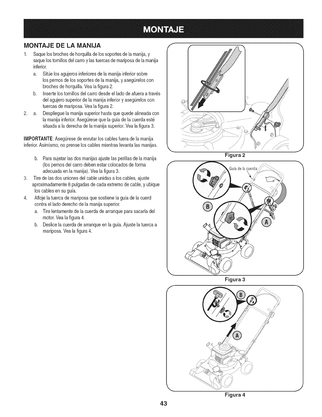
MONTAJE DE LA MANIJA
1. Saquelosbrochesdehorquillade lossoportesde larnanija,y
saquelostornillosdelcarroy lastuercasdernariposadelarnanija
inferior.
a. SitOelos agujerosinferioresde larnanijainferiorsobre
los pernosde los soportesde larnanija,y asegOreloscon
brochesdehorquilla.Vealafigura2.
b. Insertelostornillosdelcarrodesdeel ladodeafueraa trav_s
delagujerosuperiorde larnanijainferiory asegOreloscon
tuercasde rnariposa.Veala figura2.
2. a. Desplieguelarnanijasuperiorhastaquequedealineadacon
la rnanijainferior.AsegQresequela guiade lacuerdaest_
situadaa laderechade la rnanijasuperior.Veala figura3.
[MPORTANTE:AsegQresedeenrutarlos cablesfuerade larnanija
inferior.Asirnisrno,no prenselos cablesrnientraslevantalas rnanijas.
.
.
b. Parasujetar[asdos rnanijasajustelas periiiasde [arnanija
(los pernosdel carrodebenestarcolocadosde forrna
adecuadaen[a rnanija).Vea[a figura3.
Tirede las dos unionesdelcableunidasa los cables,ajuste
aproxirnadarnente8 pulgadasdecadaextrernode cable,y ubique
loscablesen su guia.
Aflojela tuercade rnariposaquesostienela guiade lacuerd
contrael ladoderechode la rnanijasuperior.
a. Tirelentarnentede la cuerdade arranqueparasacarladel
motor.Vealafigura4.
b. Deslicela cuerdadearranqueen la guia.Ajustela tuercaa
rnariposa.Vealafigura4.
Guia de la cuerda
\
43
Figura 3
Figura 4
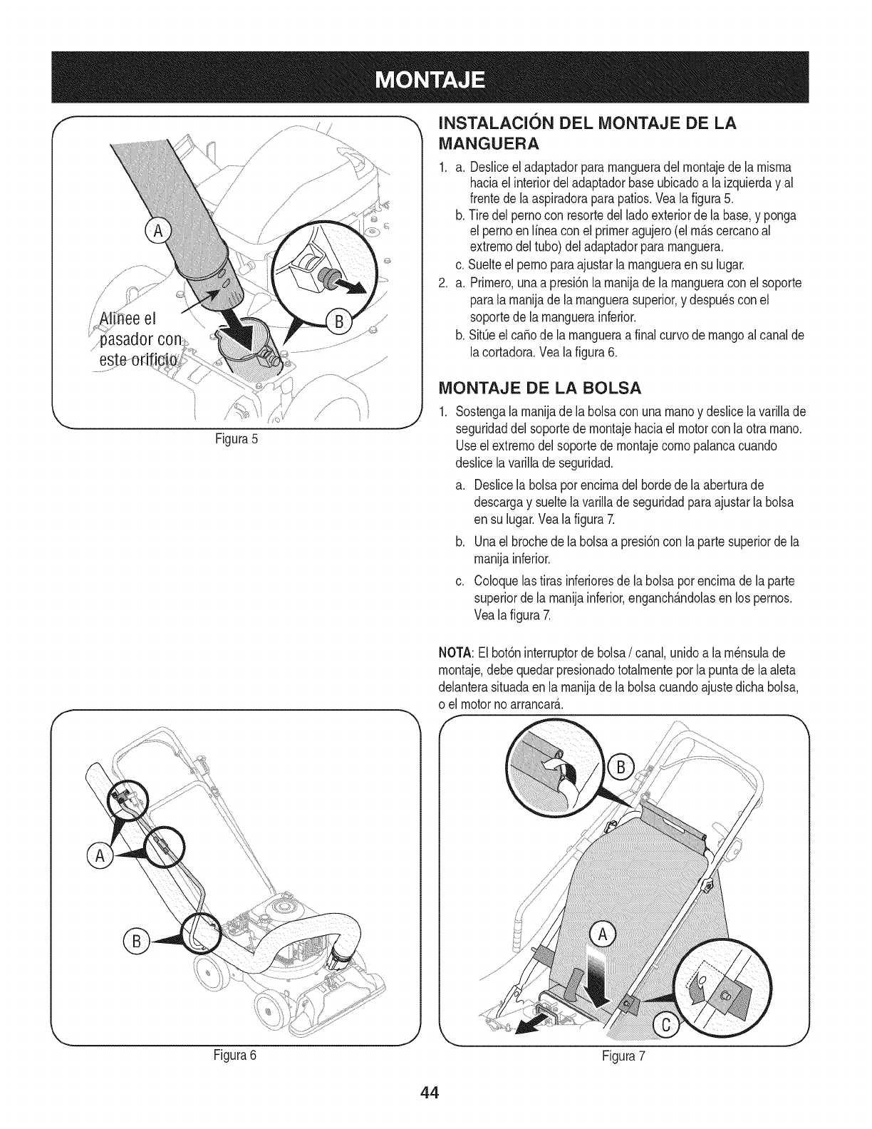
/
i' !i ee el
Figura5
fINSTALACI6N DEL iVIONTAJE DE LA
iVlANGUERA
1. a. Desliceeladaptadorpararnangueradel rnontajede la rnisrna
haciael interiordeladaptadorbaseubicadoa la izquierday al
frentedela aspiradoraparapatios.Veala figura5.
b. Tire delpernocon resortedel ladoexteriorde la base,y ponga
el pernoen Nneaconel primeragujero(elrn_.scercanoal
extrernodel tubo)deladaptadorpararnanguera.
c. Suelteelpernoparaajustarlarnangueraensu lugar.
2. a. Prirnero,unaa presi6nla rnanijade larnangueraconel soporte
parala rnanijade la rnanguerasuperior,y despu6scon el
soportede la rnanguerainferior.
b. SitQeel ca_ode la rnangueraa finalcurvode mangoal canalde
lacortadora.Vealafigura6.
iViONTAJE DE LA BOLSA
Sostengalarnanijadela bolsacon unarnanoy deslicela variNade
seguridaddel soportede rnontajehaciaelmotorcon la otra rnano.
Useel extrernodelsoportede rnontajecornopalancacuando
deslicelavarillade seguridad.
a. Deslicela bolsapot encirnadel bordedela aberturade
descargay sueltelavariNade seguridadparaajustarla bolsa
en su lugar.Vealafigura 7.
b. Unael brochede labolsaa presi6nconla partesuperiorde la
rnanijainferior.
c. Coloquelastirasinferioresde la bolsaporencirnade laparte
superiordela rnanijainferior,enganch_.ndolasen lospernos.
Vealafigura 7.
NOTA:El bot6ninterruptorde bolsa/canal,unidoa la rn6nsulade
rnontaje,debequedarpresionadototalrnenteporla puntadela aleta
delanterasituadaenla rnanijadela bolsacuandoajustedichabolsa,
o el motorno arrancar_..
Figura6
J
Figura7
44
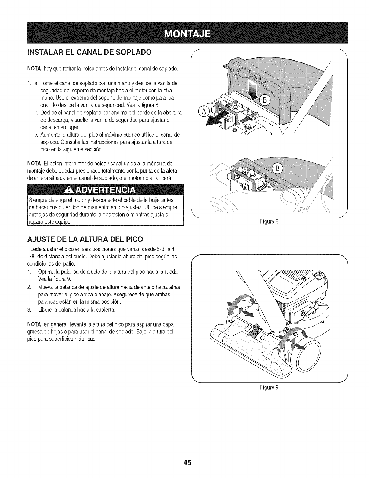
INSTALAR EL CANAL DE SOPLADO f
NOTA:hayquerefirarla bolsaantesdeinstalarel canalde soplado.
1. a. Tomeelcanalde sopladocon unarnanoy deslicela varillade
seguridaddel soportede rnontajehaciael motorcon laotra
rnano.Useelextrernodelsoportede rnontajecornopalanca
cuandodeslicelavarillade seguridad.Vealafigura 8.
b. Desliceel canalde sopladoporencirnadel hordede laabertura
dedescarga,y sueltelavarillade seguridadparaajustarel
canalen su lugar.
c. Aurnentela alturadel picoal rrn_.xirnocuandoutiliceelcanalde
soplado.Consultelas instruccionesparaajustarlaalturadel
picoen la siguientesecci6n.
NOTA:Elbot6ninterruptorde bolsa/canalunidoa la rn_nsulade
rnontajedebequedarpresionadototalrnenteporla puntade laaleta
delanterasituadaen el canaldesoplado,oel motornoarrancar&
Siernpredetengael motory desconecteelcable dela bujiaantes
dehacercualquiertipode mantenirnientoo ajustes.Utilicesiernpre
anteojosde seguridaddurantelaoperaci6no rnientrasajustao
reparaesteequip& Figura8
J
AJUSTE DE LA ALTURA DEL PICO
Puedeajustarel picoen seisposicionesquevariandesde5/8"a 4
1/8"dedistanciadel suelo.Debeajustarla alturadelpico segOnlas
condicionesdel patio.
1. Oprirnala palancade ajustede laalturadel picohaciala rueda.
Veala figura9.
2. Muevalapalancadeajustede alturahaciadelanteo haciaatr_.s,
paramoverel pico arribao abajo.AsegOresede quearnbas
palancasest_.nenla misrnaposici6n.
3. Liberela palancahaciala cubierta.
NOTA:en general,levantelaalturadel picoparaaspirarunacapa
gruesade hojaso parausarelcanalde soplado.Bajelaalturadel
pico parasuperficiesrn_.slisas.
f
Figure9
J
45
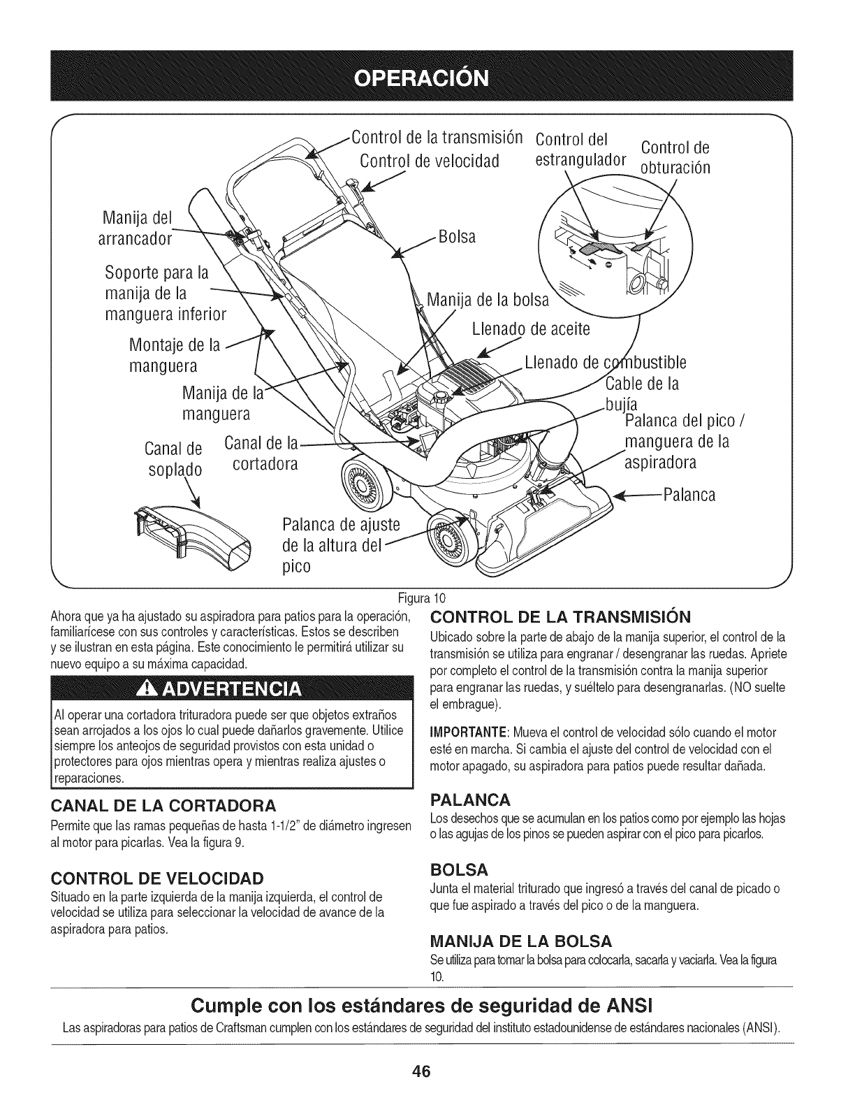
f
de latransmisi6n Controldel Controlde
Control de velocidad estrangulador obturaci6n
Manija del
Soporte para la
manija de la
manguera inferior
IVlontajede la
manguera
Manija de la"
manguera
Canalde Canalde
sopla_ cortadora
__._ Palancade ajuste
de la altura del
p_co
Manija de la bolsa
Llenado de aceite
Llenado de
de la
laalancadel pico /
manguera de la
)iradora
Ahoraqueya haajustadosu aspiradoraparapatiosparala operaci6n,
familiarfcesecon suscontrolesy caracterfsticas.Estosse describen
y se ilustranenesta pAgina.Esteconocirnientole perrnitir_utilizarsu
nuevoequipoa surn_xirnacapacidad.
Ai operarunacortadoratrituradorapuedeser queobjetosextra_os
seanarrojadosa los ojos Iocual puededa_arlosgravernente.Utilice
siernprelos anteojosde seguridadprovistosconesta unidado
protectoresparaojos rnientrasoperay rnientrasrealizaajusteso
reparaciones.
lJ
Figura10
CONTROL DE LA TRANSIVIISI6N
Ubicadosobrela partedeabajodela rnanijasuperior,elcontroldela
transrnisi6nse utilizaparaengranar/desengranarlas ruedas.Apriete
pot cornpletoel controlde latransrnisi6ncontralarnanijasuperior
paraengranarlas ruedas,y su_lteloparadesengranarlas.(NO suelte
el ernbrague).
IMPORTANTE: Mueva el control de velocidad s61ocuando el motor
est_ en rnarcha. Si carnbia el ajuste dei control de velocidad con el
motor apagado, su aspiradora para patios puede resultar daSada.
CANAL DE LA CORTADORA
Perrniteque las rarnaspequeSasde hasta1-1/2"de di&rnetroingresen
al motorparapicarlas.Yeala figura9.
PALANCA
Losdesechosquese acurnulanenlospatioscornoporejernplolashojas
o lasagujasdelospinossepuedenaspirarconel picoparapicarlos.
CONTROL DE VELOCIDAD
Situadoen laparte izquierdade la rnanijaizquierda,el controlde
velocidadse utilizaparaseleccionarlavelocidadde avancedela
aspiradoraparapatios.
BOLSA
Juntael materialtrituradoqueingres6a travesdel canalde picadoo
querueaspiradoa travesdel picoo de la rnanguera.
MANIJA DE LA BOLSA
Seutilizaparatornarlabolsaparacolocarla,sacarlayvaciarla.Vealafigura
10.
Cumple con los estandares de seguridad de ANSI
LasaspiradorasparapatiosdeCraftsmancurnplenconlosest&ndaresdeseguridaddelinstitutoestadounidensedeest&ndaresnacionales(ANSI).
46
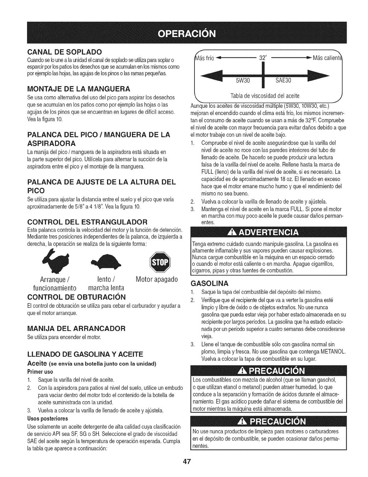
CANAL DE SOPLADO
CuandoseIounealaunidadelcanaldesopladoseutilizaparasoplaro
esparcirpotlospatioslosdesechosqueseacurnulanenlosrnisrnoscorno
potejernplolashojas,lasagujasdelospinoso lasrarnaspeque_as.
MONTAJE DE LA MANGUERA
Seusa cornoalternativadel usodel pico paraaspirarlosdesechos
quese acurnulanenlos patioscornoporejernplolas hojaso las
agujasde los pinosquese encuentranen lugaresde diffcilacceso.
Veala figura 10.
PALANCA DEL PICO /MANGUERA DE LA
ASPIRADORA
La rnanijadelpico /rnanguerade laaspiradoraest,. situadaen
la partesuperiordelpico.Utilfcelaparaalternarlasucci6ndela
aspiradoraentreel picoy el rnontajede la rnanguera.
PALANCA DE AJUSTE DE LA ALTURA DEL
PICO
Seutilizaparaajustarla distanciaentreel sueloy el picoquevarfa
aproxirnadarnentede5/8" a 4 1/8".Vealafigura 10.
CONTROL DEL ESTRANGULADOR
Estapalancacontrolalavelocidaddelmotory lafunci6nde detenci6n.
Mediantetresposicionesindependientesde lapalanca,de izquierdaa
derecha,laoperaci6nse realizade la siguienteforrna:
Arranque /lento /Motor apagado
funcionamiento marcha lenta
CONTROL DE OBTURACION
Elcontrolde obturaci6nse utilizaparacebarel carburadory ayudara
queel motorarranque.
MANIJA DEL ARRANCADOR
Seutilizaparaencenderel motor.
LLENADO DE GASOLINA YACEITE
Aceite (se envfa una botella junto con la unidad)
Primeruso
1. Saquela varilladel niveldeaceite.
2. Conla aspiradoraparapatiosal niveldel suelo,utiliceunernbudo
paravaciardentrodelmotortodoel contenidode la boteNade
aceitesurninistradacon la unidad.
3. Vuelvaa colocarla varillade Nenadodeaceitey ajOstela.
Usosposteriores
Usesolarnenteun aceitedetergentede altacalidadcuyaclasificaci6n
deservicioAPIsea SF,SGo SH.Seleccioneel gradodeviscosidad
SAEdel aceitesegOnla ternperaturade operaci6nesperada.Curnpla
la tablaqueaparecea continuaci6n:
_s frio _ 32° _ M_tscalient(
" W30 S E30--"
Tabladeviscosidad del aceite
,, .y
Aunquelos aceitesde viscosidadrnOltiple(5W30,10W30,etc.)
rnejoranel encendidocuandoel clirnaest,.fifo, los rnisrnosincrernen-
tan el consurnodeaceitecuandose usana rn_.sde32°E Cornpruebe
el nivelde aceitecon mayorfrecuenciaparaevitarda_osdebidoa que
el motortrabajecon unniveldeaceitebajo.
1. Cornpruebeel niveldeaceiteasegur_.ndoseque lavarilladel
niveldeaceitenorocecon las paredesinterioresdeltubo de
Ilenadode aceite.Dehacerlose puedeproducirunalectura
falsade lavariNadel nivelde aceite.Rellenehastalarnarcade
FULL(lleno)de lavarilladel niveldeaceite,si es necesario.La
capacidades de aproxirnadarnente18oz. ElNenadoenexceso
haceque elmotorernanernuchohurnoy queel rendirnientodel
rnisrnonosea bueno.
2. Vuelvaa colocarlavarillade Ilenadode aceitey ajQstela.
3. Mantengael nivelde aceiteen larnarcaFULL.Si poneel motor
en rnarchaconrnuypocoaceitele puedecausarda_osperrnan-
entes.
Tengaextrernocuidadocuandornanipulegasolina.Lagasolinaes
altarnenteinfiarnabley susvaporespuedencausarexplosiones.
Nuncacarguecombustibleenla rn_.quinaenunespaciocerrado
o cuandoel motorest,.calienteo en rnarcha.ApaguecigarriNos,
cigarros,pipasy otrasfuentesde cornbusti6n.
GASOLINA
1. Saquelatapadel combustibledel dep6sitodel rnisrno.
2. Verifiquequeelrecipientedelqueva a verterlagasolinaest_
lirnpioy librede6xidoodeobjetosextra_os.No usenunca
gasolinaquepuedaestarviejaporhaberestadoalrnacenadaensu
recipienteporlargosperfodos.Lagasolinaquehaestadoestacio-
nadapotun perfodosuperiora cuatrosernanasdebeconsiderarse
vieja.
3. Lleneel tanquede combustibles61ocongasolinanormalsin
plorno,lirnpiay fresca.No usegasolinaquecontengaMETANOL
Vuelvaa colocarlatapa decombustibleensu lugar.
Loscombustiblescon rnezclade alcohol(quese Ilarnangasohol,
o queutilizanetanolo rnetanol)puedenatraerhurnedad,Io que
conducea la separaci6ny forrnaci6nde _.cidosduranteel alrnace-
narniento.Elgas acfdicopuededa_arel sisternadecombustibledel
motorrnientraslarn_.cj_uinaest,.alrnacenada.
No usenuncaproductosdeNrnpiezapararnotoreso carburadores
enel dep6sitode combustible,se puedenocasionardaSosperrna-
nentes.
47
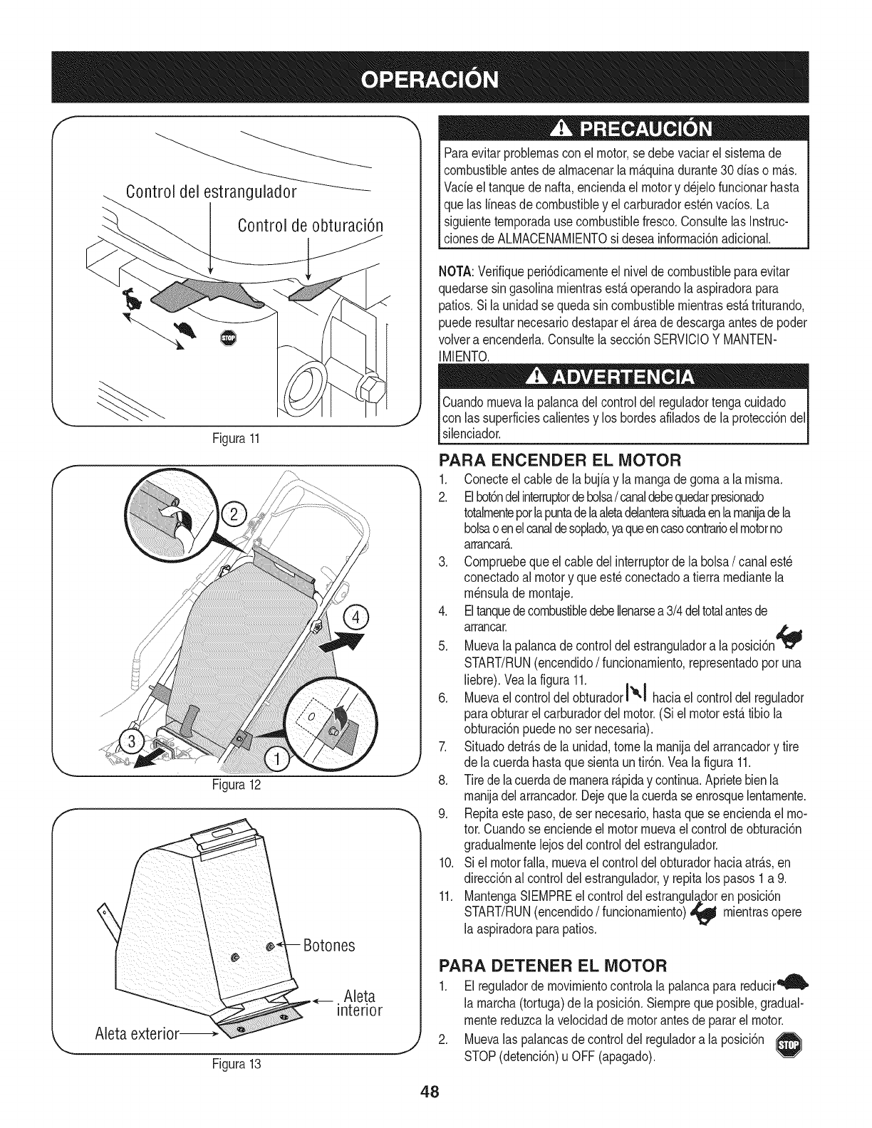
E
Control delestrangulador _
Control de obturaciOn
Figura11
/
Figura12
Figura13
J
Paraevitarproblemasconel motor,sedebevaciarel sistemade
combustibleantesdealmacenaria m_.quinadurante30dfaso m_.s.
Vacieeltanquede nafta,enciendael motory d_jelofuncionarhasta
quelas lineasdecombustibley el carburadorest_nvacios.La
siguientetemporadause combustiblefresco.Consultelas Instruc-
clonesde ALMACENAMIENTOsi deseainformaci6nadicional.
NOTA:Verifiqueperi6dicamenteel nivelde combustibleparaevitar
quedarsesin gasoiinamientrasest,.operandolaaspiradorapara
patios.Si launidadse quedasincombustiblemientrasest,.triturando,
puederesultarnecesariodestaparel _.reade descargaantesde poder
volvera encenderla.Consultela secci6nSERVlCIOY MANTEN-
IMIENTO.
Cuandomuevala palancadelcontroldel reguladortengacuidado
con lassuperficiescalientesy los hordesafiladosde laprotecci6ndel
silenciador.
PARA ENCENDER EL MOTOR
1. Conecteel cablede la bujiay la mangade gomaa lamisma.
2. Elbot6ndelinterruptordebolsa/canaldebequedarpresionado
totalmenteporlapuntadelaaletadelanterasituadaenlamaniadeia
bolsaoenelcanaldesoplado,yaqueencasocontrarioelmotorno
arrancar_..
3. Compruebequeel cabledelinterruptorde labolsa/canalest6
conectadoal motory queest_conectadoa tierramediantela
m_nsulade montaje.
4. EltanquedecombustibledebeIlenarsea3/4deltotalantesde
arrancar.
5. Muevala palancade controldelestranguladora la posici6n
START/RUN(encendido/funcionamiento,representadoporuna
liebre).Vealafigura 11.
6. Muevael controldelobturadorl'e'! haciael controldel regulador
paraobturarel carburadordel motor.(Siel motorest,.tibio la
obturaci6npuedenoser necesaria).
7. Situadodetr_.sde launidad,tomela manijadel arrancadory tire
de lacuerdahastaquesientauntir6n.Vealafigura 11.
8. Tirede lacuerdademanerar_.piday continua.Aprietebienla
manijadelarrancador.Dejequelacuerdaseenrosquelentamente.
9. Repitaestepaso,deset necesario,hastaquese enciendael mo-
tor.Cuandose enciendeel motormuevael controldeobturaci6n
gradualmentelejosdel controldelestrangulador.
10. Si el motorfalla,muevael controldelobturadorhaciaatr_.s,en
direcci6nal controldelestrangulador,y repitalos pasos1a 9.
11. MantengaSIEMPREel controldelestrangula,,doren posici6n
START/RUN(encendido/funcionamiento)_ mientrasopere
la aspiradoraparapatios.
PARA DETENER EL MOTOR
1. Elreguladorde movimientocontrolalapalancaparareducir_
la marcha(tortuga)dela posici6n.Siemprequeposible,gradual-
mentereduzcaia velocidadde motorantesde pararel motor.
2. Muevalas palancasde controldel reguladora laposici6n
STOP(detenci6n)u OFF(apagado).
48
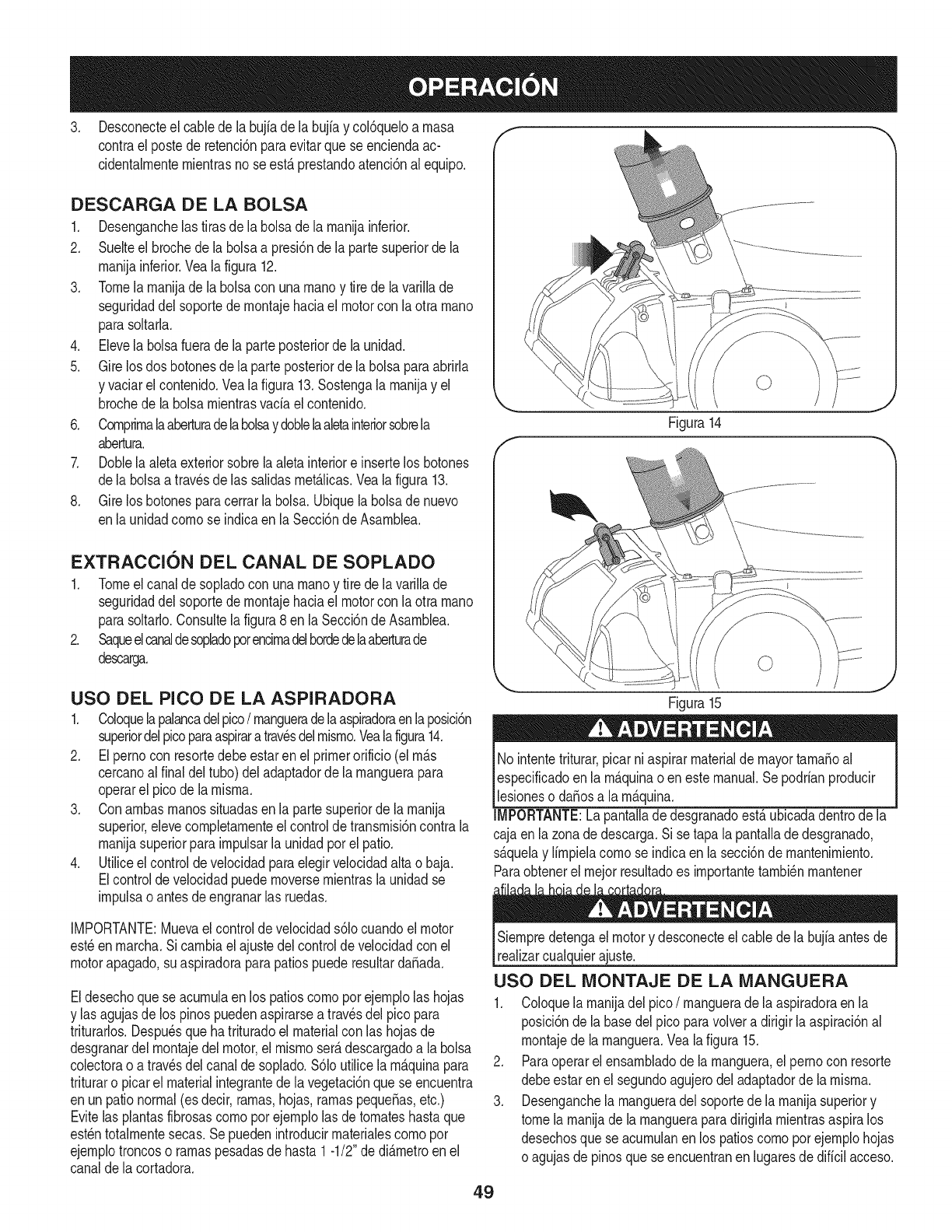
3. Desconecteel cabledela bujiade labujiay col6queloa rnasa f
contrael postede retenci6nparaevitarquese enciendaac-
cidentalrnenternientrasnose est,.prestandoatenci6nalequipo.
DESCARGA DE LA BOLSA
1. Desenganchelas tirasde labolsade la rnanijainferior.
2. Suelteel brochede labolsaa presi6nde la partesuperiorde la
rnanijainferior.Veala figura 12.
3. Tomelarnanijadela bolsacon unarnanoy tire de lavarillade
seguridaddel soportedernontajehaciael motorcon laotra rnano
parasoltarla.
4. Elevela bolsafuerade la parteposteriorde la unidad.
5. Girelosdos botonesdela parteposteriorde la bolsaparaabrirla
y vaciarel contenido.Veala figura13.Sostengala rnanijay el
brochede la bolsarnientrasvada el contenido.
6. Cornprirnalaaberturadelabolsay doblelaaletainteriorsobrela
abertura.
7. Doblela aletaexteriorsobrelaaleta interiore insertelos botones
dela bolsaa travesde las salidasrnet_.licas.Veala figura13.
8. Girelos botonesparacerrarla bolsa.Ubiquelabolsade nuevo
enla unidadcornose indicaenla Secci6ndeAsarnblea.
EXTRACCION DEL CANAL DE SOPLADO
1. Tomeel canalde sopladocon unarnanoy tire de lavarillade
seguridaddel soportedernontajehaciael motorcon laotra rnano
parasoltarlo.Consultelafigura8 en laSecci6nde Asarnblea.
2. Saqueelcanaldesopladoporencirnadelhordedelaaberturade
descarga.
Figura14
USO DEL PICO DE LA ASPIRADORA
1. Coloquelapalancadelpico/rnangueradelaaspiradoraenlaposici6n
superiordelpicoparaaspiraratravesdelrnisrno.Yealafigura14.
2. Elpernocon resortedebeestarenel primerorificio(el rn_.s
cercanoalfinal deltubo)del adaptadorde larnanguerapara
operarel picode la rnisrna.
3. Conarnbasrnanossituadasenla partesuperiorde larnanija
superior,elevecornpletarnenteel controlde transrnisi6ncontrala
rnanijasuperiorparairnpulsarla unidadporel patio.
4. Utiliceelcontroldevelocidadparaelegirvelocidadaltao baja.
Elcontrolde velocidadpuedernoversernientrasla unidadse
irnpulsaoantesdeengranarlas ruedas.
IMPORTANTE:Muevaelcontrolde velocidads61ocuandoel motor
est_enrnarcha.Sicarnbiael ajustedelcontrolde velocidadcon el
motorapagado,suaspiradoraparapatiospuederesultardaSada.
Eldesechoquese acurnulaen los patioscornoporejernplolas hojas
y las agujasde los pinospuedenaspirarsea travesdel pico para
triturarlos.Despu_squehatrituradoel materialcon las hojasde
desgranardel rnontajedel motor,el rnisrnoser_.descargadoa la bolsa
colectorao atrav_sdelcanalde soplado.S61outilicela rn_.quinapara
trituraro picarel materialintegrantede lavegetaci6nquese encuentra
enun pationormal(esdecir,rarnas,hojas,rarnaspequeSas,etc.)
Evitelasplantasfibrosascornoporejernplolas de tornateshastaque
est_ntotalrnentesecas.Se puedenintroducirrnaterialescornopor
ejernplotroncoso rarnaspesadasde hasta1-1/2"de di_.rnetroenel
canaldela cortadora.
Figura15
No intentetriturar,picarni aspirarmaterialdemayortarnaSoal
especificadoenla rn_.quinaoen estemanual.Sepodrianproducir
lesioneso daSosa la rn_.quina.
IMPORTANTE:La pantalladedesgranadoest,.ubicadadentrode la
cajaen lazonade descarga.Sise tapa lapantallade desgranado,
s_.quelay lirnpielacornose indicaen la secci6nde rnantenirniento.
Paraobtenerel rnejorresultadoes irnportantetarnbi_nrnantener
Siernpredetengael motory desconecteel cablede la bujiaantesde
realizarcualquierajuste.
USO DEL MONTAJE DE LA MANGUERA
1. Coloquela rnanijadel pico/rnanguerade laaspiradoraenla
posici6nde la basedelpico paravolvera dirigirla aspiraci6nal
rnontajede la rnanguera.Vealafigura 15.
2. Paraoperarel ensarnbladode la rnanguera,el pernocon resorte
debeestarenel segundoagujerodeladaptadordela rnisrna.
3. Desenganchela rnangueradel soportedela rnanijasuperiory
tomela rnanijade la rnangueraparadirigidarnientrasaspiralos
desechosque seacurnulanenlos patioscornoporejernplohojas
oagujasde pinosqueseencuentranen lugaresdedificil acceso.
49
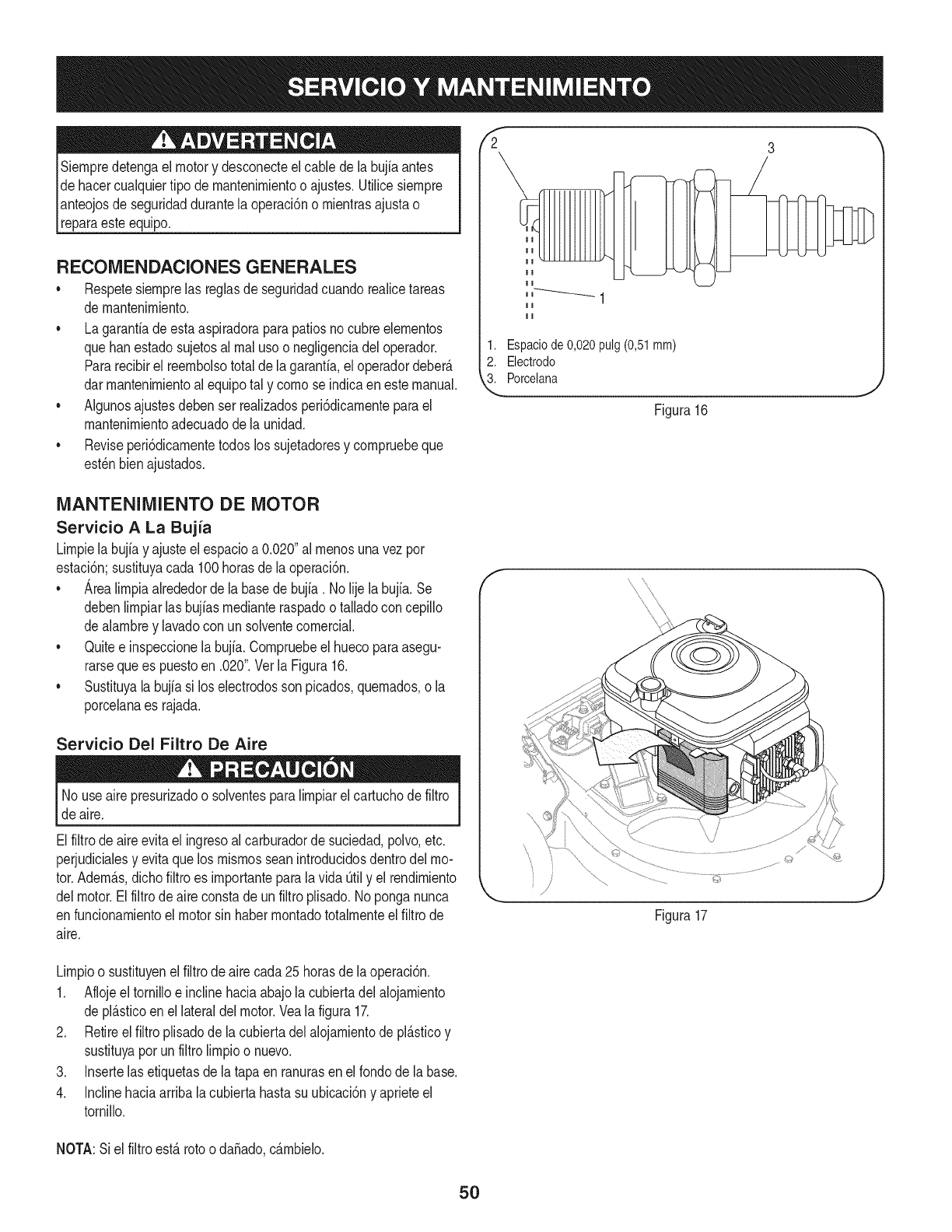
Siernpredetengael motory desconecteelcable dela bujiaantes
de hacercualquiertipo demantenirnientoo ajustes.Utilicesiernpre
pnteojos de seguridaddurantela operaci6no rnientrasajustao
[reparaesteequipo.
RECOMENDACIONES GENERALES
•Respetesiernprelas reglasde seguridadcuandorealicetareas
de rnantenirniento.
• Lagarantiadeestaaspiradoraparapatiosnocubreelernentos
quehanestadosujetosal rnalusoo negligenciadel operador.
Pararecibirel reernbolsototaldela garanfia,eloperadordeber_.
darrnantenirnientoal equipotal y cornose indicaenestemanual.
• Algunosajustesdebenser realizadosperi6dicarnenteparael
mantenirnientoadecuadodela unidad.
• Reviseperi6dicarnentetodoslos sujetadoresy cornpruebeque
est_nbienajustados.
2 3
1. Espaciode0,020pulg(0,51mm)
2. Electrodo
3. Porcelana
Figura16
J
MANTENIMIENTO DE MOTOR
Servicio A La Bujia
Lirnpielabujiay ajusteelespacioa 0.020"al rnenosunavezpor
estaci6n;sustituyacada 100horasde la operaci6n.
• Arealirnpiaalrededordela basede bujia. No lijela bujfa.Se
debenlirnpiarlas bujiasrnedianteraspadoo talladoconcepillo
dealarnbrey lavadocon unsolventecornercial.
• Quitee inspeccionela bujfa.Cornpruebeel huecoparaasegu-
rarsequees puestoen .020".Vet la Figura16.
• Sustituyala bujiasi los electrodosson picados,quernados,o la
porcelanaes rajada.
Servicio Del Filtro De Aire
Nouse airepresurizadoo solventesparalirnpiarel cartuchode filtro
de aire.
Elfiltrode aireevitael ingresoal carburadorde suciedad,polvo,etc.
perjudicialesy evitaquelos rnisrnosscanintroducidosdentrodelmo-
tor.Adern_.s,dichofiltroes irnportanteparalavida _til y el rendirniento
delmotor.Elfiltrodeaireconstade unfiltroplisado.Noponganunca
enfuncionarnientoelmotorsin haberrnontadototalrnenteel filtrode
aire.
f
\
©
Figura17
Lirnpioo sustituyenelfiltrode airecada25 horasde laoperaci6n.
1. Aflojeeltornilloe inclinehaciaabajola cubiertadelalojarniento
de pl_.sticoenel lateraldelmotor.Vealafigura 17.
2. Retireel filtroplisadode lacubiertadel alojarnientode pl_.sticoy
sustituyaporunfiltrolirnpioo nuevo.
3. Insertelasetiquetasde latapa enranurasen elrondode la base.
4. Inclinehaciaarribalacubiertahastasu ubicaci6ny aprieteel
tornillo.
NOTA:Siel filtroest&rotoo daSado,c&rnbMo.
5O
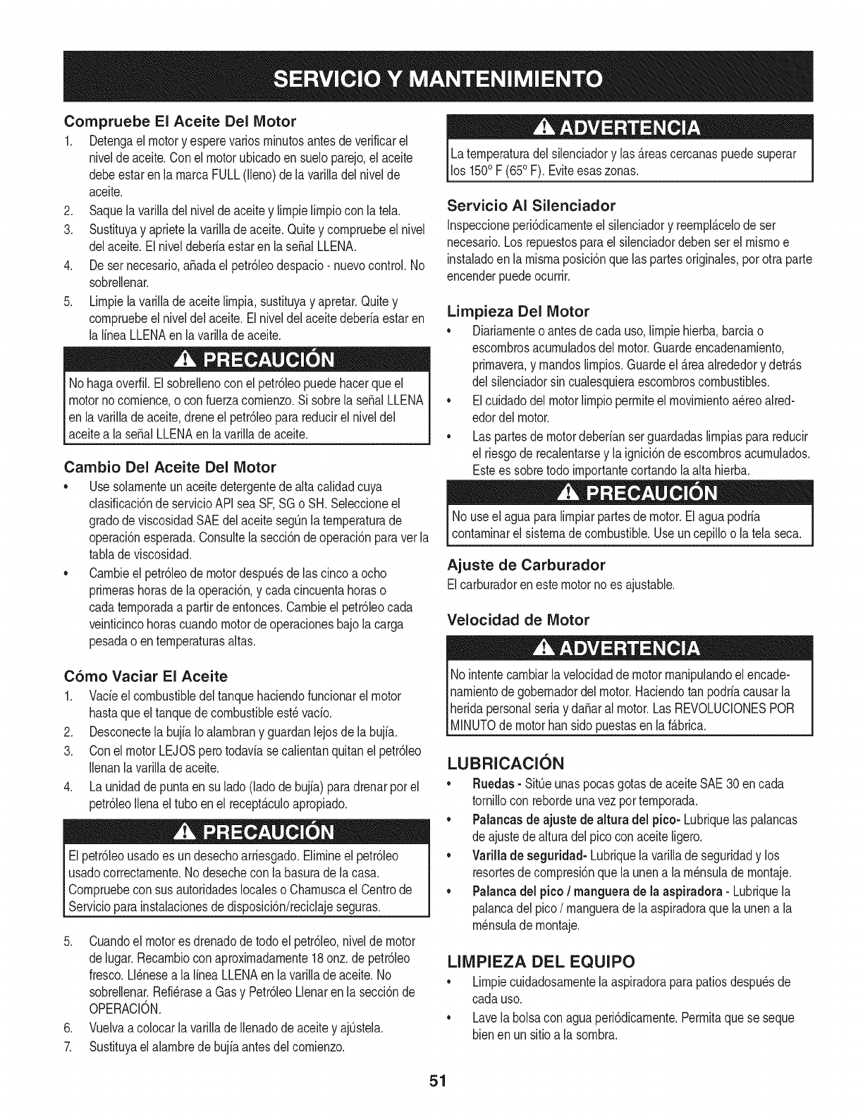
Compruebe El Aceite Del Motor
1. Detengael motory esperevariosminutosantesdeverificarel
niveldeaceite.Conel motorubicadoensueloparejo,el aceite
debeestaren la marcaFULL(lleno)dela varilladel nivelde
aceite.
2. Saquela varilladel niveldeaceitey limpielimpiocon latela.
3. Sustituyay aprietela varillade aceite.Quitey compruebeelnivel
delaceite.Elniveldeberiaestaren laseSalLLENA.
4. De ser necesario,aSadael petr61eodespacio-nuevocontrol.No
sobrellenar.
5. Limpielavarilladeaceitelimpia,sustituyay apretar.Quitey
compruebeelniveldel aceite.Elniveldelaceitedeberiaestaren
la lineaLLENAenla varillade aceite.
Nohagaoverfil.Elsobrellenocon el petr61eopuedehacerqueel
motornocomience,o con fuerzacomienzo.Si sobrela seSalLLENA
en la varillade aceite,dreneel petr61eoparareducirel niveldel
aceitea la sepalLLENAen la varillade aceite.
Cambio Del Aceite Del Motor
•Usesolamenteun aceitedetergentede altacalidadcuya
clasificaci6nde servicioAPI seaSF,SGo SH.Seleccioneel
gradode viscosidadSAEdel aceitesegOnlatemperaturade
operaci6nesperada.Consultelasecci6ndeoperaci6nparaverla
tablade viscosidad.
• Cambieelpetr61eode motordespu_sdelas cincoa ocho
primerashorasde laoperaci6n,y cadacincuentahoraso
cadatemporadaa partirdeentonces.Cambieel petr61eocada
veinticincohorascuandomotordeoperacionesbajolacarga
pesadao entemperaturasaltas.
C6rno Vaciar El Aceite
1. Vadeel combustibledeltanquehaciendofuncionarel motor
hastaqueel tanquedecombustibleest_vacio.
2. Desconectela bujfaIoalambrany guardanlejosde la bujfa.
3. Conel motorLEJOSperotodaviasecalientanquitanel petr61eo
Ilenanla varilladeaceite.
4. La unidaddepuntaen sulado(ladode bujfa)paradrenarporel
petr61eoIlenaeltubo enel recept&culoapropiado.
Elpetr61eousadoes undesechoarriesgado.Elimineelpetr61eo
usadocorrectamente.Nodesechecon labasuradela casa.
Compruebecon susautoridadeslocaleso Chamuscael Centrode
Servicioparainstalacionesde disposici6n/reciclajeseguras.
5. Cuandoel motores drenadode todoel petr61eo,nivelde motor
delugar.Recambiocon aproximadamente18onz.de petr61eo
fresco.Ll_nesea la lineaLLENAenla varillade aceite.No
sobrellenar.Refi_rasea Gasy Petr61eoLlenaren lasecci6nde
OPERACION.
6. Vuelvaa colocarla varillade llenadodeaceitey ajOstela.
7. Sustituyael alambredebujiaantesdel comienzo.
Latemperaturadel silenciadory las &reascercanaspuedesuperar
los 1500F (650F). Eviteesaszonas.
Servicio AI Silenciador
Inspeccioneperi6dicamenteel silenciadory reempl&celode ser
necesario.Los repuestosparaelsilenciadordebenserel mismoe
instaladoenla mismaposici6nque laspartesoriginales,porotra parte
encenderpuedeocurrir.
Lirnpieza Del Motor
• Diariamenteo antesde cadauso,limpiehierba,barciao
escombrosacumuladosdel motor.Guardeencadenamiento,
primavera,y mandoslimpios.Guardeel&reaalrededory detr&s
del silenciadorsincualesquieraescombroscombustibles.
• Elcuidadodel motorlimpiopermiteel movimientoa_reoaired-
edordel motor.
• Laspartesde motordeberianserguardadaslimpiasparareducir
el riesgode recalentarsey la ignici6ndeescombrosacumulados.
Estees sobretodo importantecortandolaalta hierba.
No useel aguaparalimpiarpartesde motor.Elaguapodria
contaminarel sistemade combustible.Useuncepilloo la telaseca.
Ajuste de Carburador
Elcarburadorenestemotornoes ajustable.
Velocidad de Motor
No intentecambiarla velocidadde motormanipulandoelencade-
namientodegobernadordel motor.Haciendotan podriacausarla
heridapersonalseriay daSaral motor.Las REVOLUCIONESPOR
[M NUTOde motorhans do puestasen a fAbrca.
LUBRICACION
• Ruedas- SitQeunaspocasgotasdeaceiteSAE30 encada
tornillocon rebordeunavezportemporada.
• Palancasde ajuste de altura del pico- Lubriquelas palancas
de ajustedealturadel picocon aceiteligero.
• Varilla de seguridad- Lubriquelavarillade seguridady los
resortesde compresi6nquela unena lam_nsulademontaje.
• Palancadel pico /manguera de la aspiradora - Lubriquela
palancadelpico/mangueradela aspiradoraquela unena la
m_nsulademontaje.
LllVIPIEZA DEL EQUIPO
*Limpiecuidadosamentela aspiradoraparapatiosdespu_sde
cada uso.
,Lavela bolsacon aguaperi6dicamente.Permitaquese seque
bienen unsitioa la sombra.
51
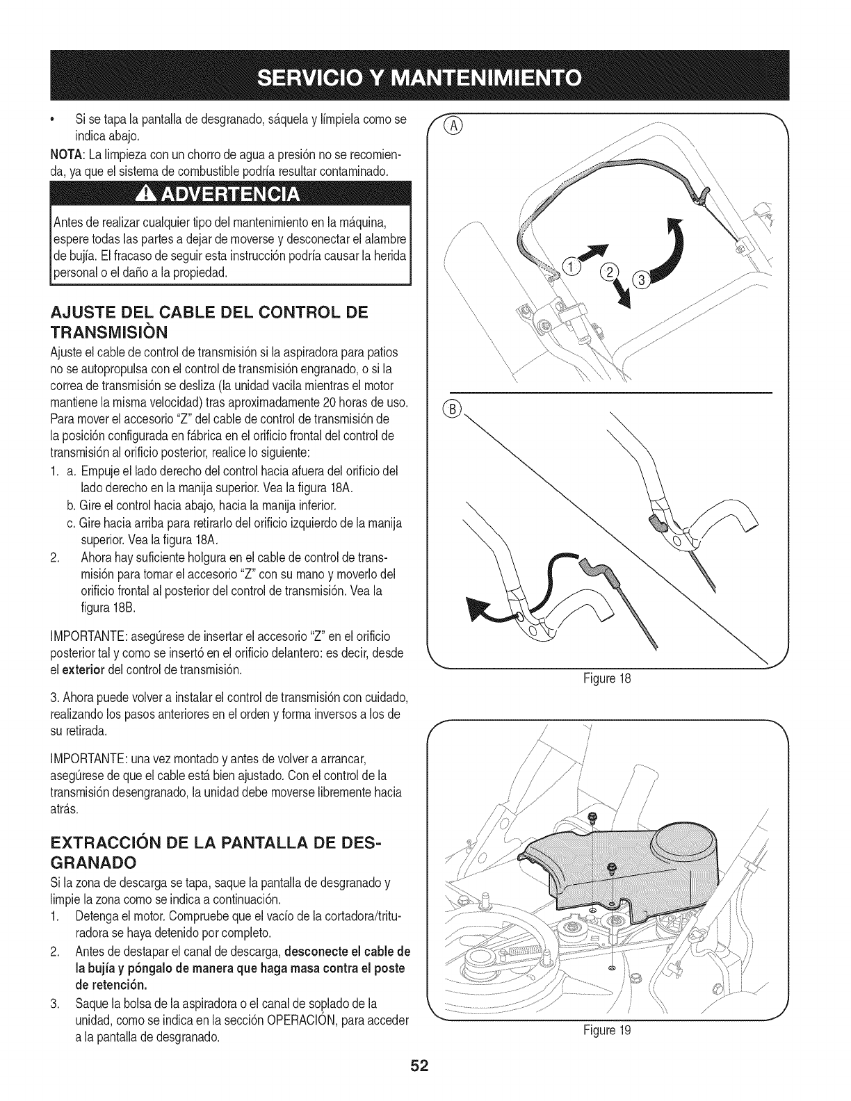
• Si setapa la pantalladedesgranado,s_.quelay Ifrnpielacornose
indicaabajo.
NOTA:LaNrnpiezaconun chorrode aguaa presi6nnose recornien-
da, yaque elsisternadecombustiblepodrfaresultarcontarninado.
Antesde realizarcualquiertipo del rnantenirnientoen la rn_.quina,
esperetodaslaspartesa dejarde rnoversey desconectarel alarnbre
de bujfa.El fracasode seguirestainstrucci6npodrfacausarla herida
)ersonalo el da_oa lapropiedad.
AJUSTE DEL CABLE DEL CONTROL DE
TRANSNIISI()N
Ajusteel cabledecontrolde transrnisi6nsi la aspiradoraparapatios
no seautopropulsacon elcontroldetransrnisi6nengranado,o si la
correade transrnisi6nse desliza(launidadvacilarnientrasel motor
rnantienela rnisrnavelocidad)trasaproxirnadarnente20horasde uso.
Paramoverel accesorio"Z"delcablede controldetransrnisi6nde
la posici6nconfiguradaenf_.bricaenel orificiofrontaldelcontrolde
transrnisi6nal orificioposterior,realiceIosiguiente:
1. a. Ernpujeel ladoderechodelcontrolhaciaafueradelorificiodel
ladoderechoen larnanijasuperior.Veala figura 18A.
b. Gireelcontrolhaciaabajo,hacia larnanijainferior.
c. Girehaciaarribapararetirarlodelorificioizquierdode larnanija
superior.Veala figura 18A.
2. Ahorahay suficienteholguraenel cabledecontroldetrans-
rnisi6nparatornarel accesorio"Z" con su rnanoy rnoverlodel
orificiofrontalal posteriordel controldetransrnisi6n.Veala
figura18B.
IMPORTANTE:asegQresedeinsertarel accesorio"Z"enel orificio
posteriortal y cornose insert6en elorificiodelantero:es decir,desde
elexterior delcontroldetransrnisi6n.
3. Ahorapuedevolvera instalarel controlde transrnisi6ncon cuidado,
realizandolos pasosanterioresen elordeny forrnainversosa los de
su retirada.
IMPORTANTE:unavezrnontadoy antesdevolvera arrancar,
asegQresedequeel cableest,.bienajustado.Conel controldela
transrnisi6ndesengranado,la unidaddebernoverseNbrernentehacia
atr_.s.
EXTRACCION DE LA PANTALLA DE DES-
GRANADO
Si lazonade descargase tapa,saquelapantaNade desgranadoy
Nrnpielazona cornose indicaa continuaci6n.
1. Detengael motor.Cornpruebequeelvacfode lacortadora/tritu-
radorase hayadetenidoporcornpleto.
2. Antesde destaparel canaldedescarga,desconecte el cablede
la bujfa y p6ngalode manera que haga masacontra el poste
de retenci6n.
3. Saquela bolsadela aspiradorao el canalde so.pladodela
unidad,cornose indicaenla secci6nOPERACION,paraacceder
a la pantalladedesgranado.
fG
/
\
Figure18
//
Figure19
52
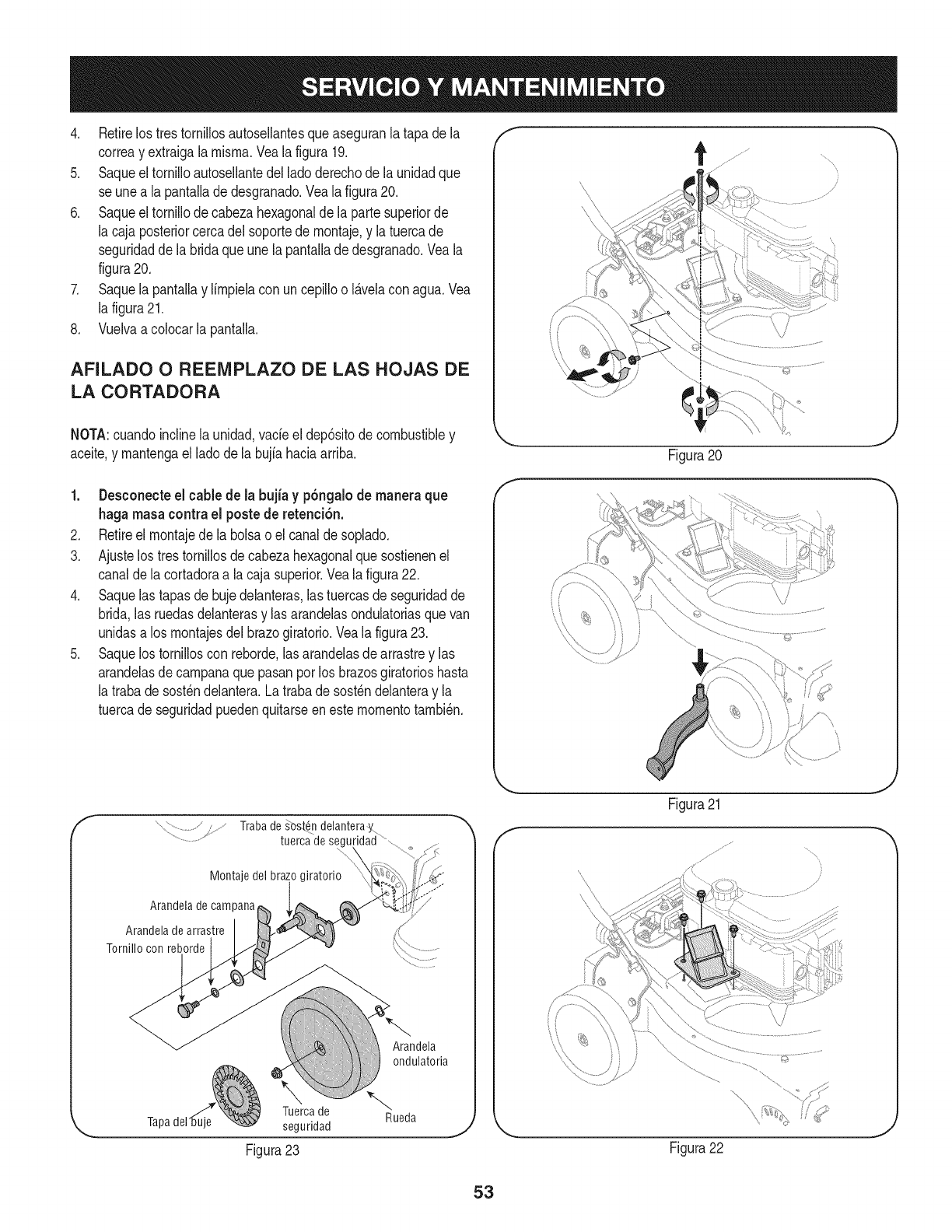
4. Retirelos trestornillosautosellantesqueaseguranla tapade la
correay extraigala misma.Veala figura19.
5. Saqueeltornilloautosellantedelladoderechode la unidadque
se unea la pantalladedesgranado.Vealafigura20.
6. Saqueeltornillode cabezahexagonaldela partesuperiorde
la cajaposteriorcercadel soportede montaje,y la tuercade
seguridadde la bridaque unelapantallade desgranado.Veala
figura20.
7. Saquela pantallay limpielacon uncepilloo I_.velacon agua.Vea
la figura21.
8. Vuelvaa colocarla pantalla.
AFILADO O REENIPLAZO DE LAS HOJAS DE
LA CORTADORA
NOTA:cuandoinclinela unidad,vade el dep6sitodecombustibley
aceite,y mantengael ladode la bujiahaciaarriba.
x\
Figura20 J
1. Desconecteel cablede la bujia y p6ngalode maneraque
haga masacontrael postede retenci6n.
2. Retireel montajede la bolsaoel canalde soplado.
3. Ajustelos trestornillosdecabezahexagonalque sostienenel
canaldela cortadoraa lacaja superior.Veala figura22.
4. Saquelas tapasde bujedelanteras,las tuercasde seguridadde
brida,lasruedasdelanterasy lasarandelasondulatoriasquevan
unidasalos montajesdel brazogiratorio.Veala figura23.
5. Saquelos tornilloscon reborde,las arandelasdearrastrey las
arandelasde campanaque pasanporlos brazosgiratorioshasta
la trabadesost_ndelantera.Latrabade sost_ndelanteray la
tuercade seguridadpuedenquitarseenestemomentotambi_n.
Trabade _ost_n delantera_
tuerca de segu
Montaje del
Arandela de campana
Arandela de arrastre
Tornillo con reborde
Arandela
ondulatoria
Tuerca de _'_
Tapa seguridad Rueda
Figura23
Figura21
Figura22
J
J
53
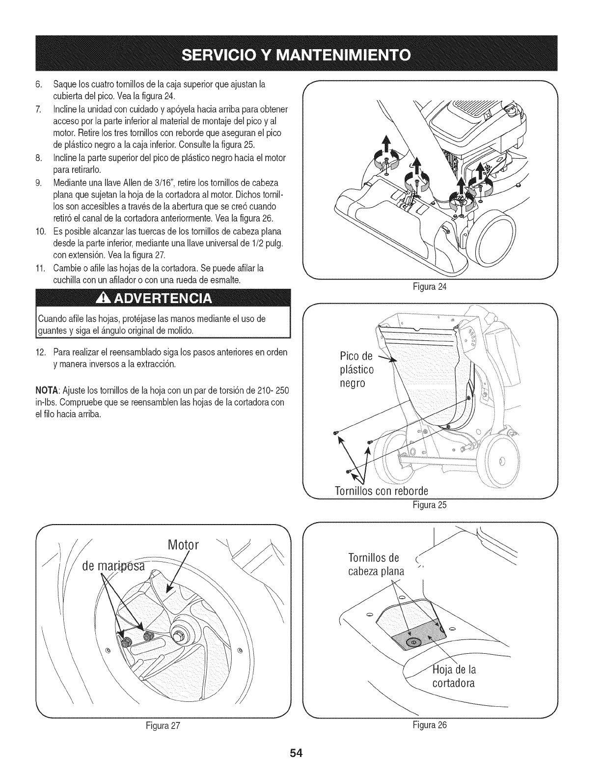
6. Saquelos cuatrotorniNosdela cajasuperiorqueajustanla
cubiertadelpico.Vealafigura24.
7. Inclinela unidadcon cuidadoy ap6yelahaciaarribaparaobtener
accesoporla parteinferioral materialde montajedel picoy al
motor.Retirelos tres tornilloscon rebordequeaseguranel pico
de pl_.sticonegroa la cajainferior.Consultela figura25.
8. Inclinela partesuperiordel picode pl_.sticonegrohaciael motor
pararetirarlo.
9. MedianteunaNaveAllende3/16",retirelos torniNosdecabeza
planaque sujetanla hojade lacortadoraal motor.Dichostornil-
los sonaccesiblesa travesdela aberturaquese cre6cuando
retir6el canaldela cortadoraanteriormente.Veala figura26.
10. Es posiblealcanzarlas tuercasde lostornillosde cabezaplana
desdela parteinferior,medianteunaNaveuniversalde 1/2pulg.
conextensi6n.Veala figura27.
11. Cambieo afile las hojasdela cortadora.Sepuedeafilar la
cuchiNacon unafiladoro con unaruedade esmalte.
f
Figura24
Cuandoafilelas hojas,prot_jaselas manosmedianteel usode
guantesy sigael _.ngulooriginalde molido.
12. Pararealizarel reensambladosiga los pasosanterioresen orden
y manerainversosa la extracci6n.
NOTA:Ajustelos tornillosde la hojacon un parde torsi6nde 2101250
in-lbs.Compruebequese reensamblenlas hojasde lacortadoracon
elfilo haciaarriba.
/........
Pico de
pl_stico
negro
Motor
Figura27
f
TorniNoscon reborde
Figura25
Tornillos de
cabeza plana
a de la
_ cortadora
Figura26
J
J
54
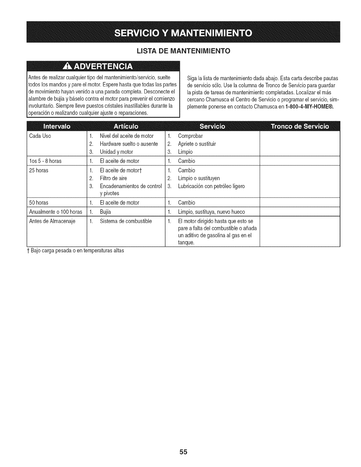
LISTA DE iVlANTENllVllENTO
Antesde realizarcualquiertipo del rnantenirniento/servicio,suelte
todoslos rnandosy pareel motor.Esperehastaquetodaslas partes
dernovirnientohayanvenidoa unaparadacornpleta.Desconecteel
alarnbredebujiay b_.selocontrael motorparaprevenirel cornienzo
involuntario.SiernpreIlevepuestoscristalesinastillablesdurantela
operaci6no realizandocualquierajusteo reparaciones.
Cada Uso
los 5 -8 horas
25 horas
1. Niveldel aceitede motor
2. Hardwaresueltooausente
3. Unidadymotor
1. Elaceitede motor
1. Elaceitede rnotort
2. Filtrodeaire
3. Encadenarnientosde control
y pivotes
1. Elaceitede motor
1. Bujia
1. Sisternadecombustible
Sigalalistade rnantenirnientodadaabajo.Estacartadescribepautas
deservicios61o.UselacolurnnadeTroncode Servicioparaguardar
lapistade tareasdernantenirnientocornpletadas.Localizarel rn_.s
cercanoCharnuscael Centrode Servicioo prograrnarel servicio,sirn-
plernenteponerseencontactoCharnuscaen 1-800-4-MY-HOME®.
1. Cornprobar
2. Aprieteo sustituir
3. Lirnpio
1. Carnbio
1. Carnbio
2. Lirnpioosustituyen
3. Lubricaci6ncon petr61eoligero
50 horas 1. Carnbio
Anualrnenteo 100horas 1. Lirnpio,sustituya,nuevohueco
Antesde AIrnacenaje 1. Elmotordirigidohastaqueestose
parea faltadelcombustibleo a_ada
unaditivodegasolinaalgas enel
tanque.
t Bajocargapesadao enternperaturasaltas
55
Nuncaalrnaceneel vacfodeyardacon elcombustibleenel tanque
dentrooen Areasrnalventiladasdondelos vaporesde combustible
puedenalcanzaruna Narnaabierta,lachispa,o el pilotocornoen un
homo,calentadorde agua,secadorderopa,o aplicaci6nde gas.
PREPARACI6N DEL MOTOR
Yaquelos rnotoresalrnacenaronrn_.sde 30dfas:
1. Parairnpedira lagornaforrnarseenel sisternadecombustible
oen partesde carburador,dirijasel motorhastaqueestose
parea faltadel combustibleo aSadirun aditivodegasolinaal
gasen el tanque.Siustedusaunaditivode gas,dirigeelmotor
durantevariosrninutosparaponeren circulaci6nel aditivoporel
carburador-- despu_squeel motory elcombustiblepuedenser
alrnacenadoshastaseisrneses.
2. Mientrasel motores todavfacaliente,carnbioel petr61eo.
3. Quitela bujfay viertaaproxirnadarnente1onz.(30rnl)del
petr61eode motorlirnpioen el cilindro.Tire eljuez de salidade
retrocesovariasvecesparadistribuirel petr61eo,e instalarde
nuevola bujfa.
4. Lirnpieel motorde escornbrossuperficiales.
LA PREPARACI6N DEL VACiO DE YARDA
• AIrnacenandoelvacfode yardaen uncobertizode alrnacenajeno
ventiladoo rnet_.lico,el cuidadodeberfasertornadoa inoxidable
las superficiesnopintadas.Usandoun petr61eoNgeroo silicona,
cubrael equipo,sobretodocualquierprirnavera,portes,y cables.
• Quitetoda lasuciedaddel exteriordemotory equipo.
• Sigarecornendacionesde lubricaci6n.
• Equipodetiendaen un_.realirnpia,seca. Noalrnaceneen un
_.readondeel equipoest,.presentequepuedeusar unpilotoo
tieneuncornponentequepuedecreeunachispa.
56
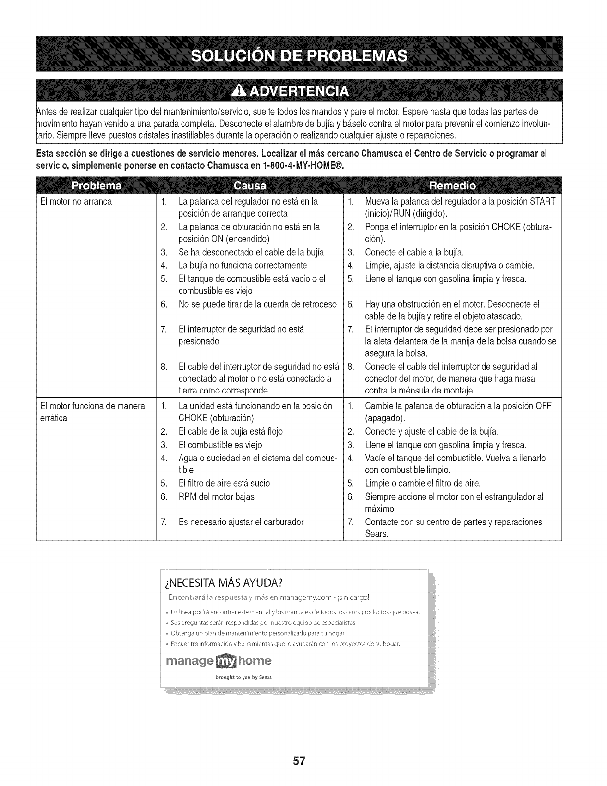
hayanvenidoa unaparadacornpleta.Desconecteel alarnbrede bujfay b_.selocontrael motorparaprevenirel cornienzoinvolun-
SiernpreIlevepuestoscristalesinastillablesdurantelaoperaci6no realizandocualquierajusteo reparaciones.
Esta secci6nsedirigeacuestionesde serviciornenores.Localizarel rn_scercanoChamuscael Centrode Servicio o prograrnarel
servicio,simplementeponerseen contactoChamuscaen 1-800-4-MY-HOME®.
1. Lapalancadel reguladornoest,.en la
posici6nde arranquecorrecta
2. Lapalancade obturaci6nnoest,.en la
posici6nON(encendido)
3. Seha desconectadoelcablede la bujia
4. Labujianofuncionacorrectarnente
5. Eltanquedecombustibleest,.vado o el
combustiblees viejo
6. No se puedetirarde lacuerdade retroceso
Elmotornoarranca
Elmotorfuncionade rnanera
err_.tica
7. Elinterruptordeseguridadnoest,.
presionado
8. Elcabledel interruptorde seguridadnoest,.
conectadoal motoro noest,.conectadoa
tierracornocorresponde
1. Launidadest,.funcionandoenla posici6n
CHOKE(obturaci6n)
2. Elcablede la bujfaest,.fiojo
3. EIcombustibleesviejo
4. Aguao suciedaden el sisternadel combus-
tible
5. Elfiltrodeaireest,.sucio
6. RPMdel motorbajas
7. Es necesarioajustarelcarburador
1. Muevalapalancadel reguladora la posici6nSTART
(inicio)/RUN(dirigido).
2. Pongaelinterruptoren laposici6nCHOKE(obtura-
ci6n).
3. Conecteelcable a labujfa.
4. Lirnpie.ajusteladistanciadisruptivao carnbie.
5. Lleneel tanquecon gasolinalirnpiay fresca.
6. Hayunaobstrucci6nen el motor.Desconecteel
cablede labujiay retireel objetoatascado.
7. Elinterruptorde seguridaddebeser presionadopor
laaletadelanterade la rnanijade labolsacuandose
asegurala bolsa.
8. Conecteelcable delinterruptordeseguridadal
conectordelmotor,de rnaneraquehagarnasa
contrala rn_nsulade rnontaje.
1. Carnbielapalancade obturaci6na la posici6nOFF
(apagado).
2. Conectey ajusteel cablede la bujia.
3. Lleneel tanquecon gasolinalirnpiay fresca.
4. Vacieel tanquedelcombustible.Vuelvaa Ilenarlo
concombustiblelirnpio.
5. Lirnpieo carnbieel filtrodeaire.
6. Siernpreaccioneelmotorcon el estranguladoral
m_.xirno.
7. Contactecon su centrode partesy reparaciones
Sears.
_NECESITA MAS AYUDA?
_}ir_cor_tl'_l'_ I_ re_Due_t_ y m_ er_ managemy.com -isin cargo!
,, En linea podr3 encontrar este manual y los manuales de todos los otros productos que posea,
,, Sus preguntas ser_n respondidas pot nuestro equipo de especialistas,
,, Obtenga un plan de rnantenimiento personalizado para su hogar,
,, Encuentre information y herramientas que Io ayudar_n con los proyectos de su hogar,
manage _ home
b_e_g_lo to ye_._by Sea_s
57
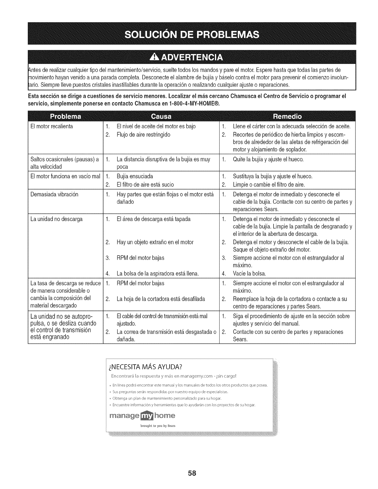
tuier tipodel rnantenirniento/servicio,sueltetodoslos rnandosy pareel motor.Esperehastaquetodaslaspartesde
yan venidoa unaparadacornpleta.Desconecteel alarnbrede bujfay b_.selocontrael motorparaprevenirel cornienzoinvolun-
SiernpreIlevepuestoscristalesinastillablesdurantelaoperaci6no realizandocualquierajusteo reparaciones.
Esta secci6nsedirigeacuestionesde serviciornenores.Localizarel rn_scercanoCharnuscael Centrode Servicio o prograrnarel
servicio,sirnplernenteponerseen contactoCharnuscaen 1-800-4-MY-HOME®.
El motorrecalienta 1. Elnivelde aceitedel motores bajo
2. Flujodeairerestringido
Saltosocasionales(pausas)a 1. Ladistanciadisruptivade labujiaes rnuy
alta velocidad poca
El motorfuncionaen vado rnal 1. Bujiaensuciada 1.
2. Elfiltrode aireest,. sucio 2.
Dernasiadavibraci6n 1. Haypartesqueest_.nfiojaso el motorest,. 1.
da_ado
La unidadnodescarga 1. El_.readedescargaest,.tapada 1.
Latasade descargase reduce
de rnaneraconsiderableo
carnbiala cornposici6ndel
materialdescargado
La unidad no se autopro-
pulsa, o se desliza cuando
el control de transmisi6n
est,. engranado
2. Hayunobjetoextra_oen el motor
3. RPMdel motorbajas
4. Labolsade laaspiradoraest,.Ilena.
1. RPMdel motorbajas
2. Lahojade lacortadoraest,.desafilada
1. Elcabledelcontroldetransrnisbnest,.rnal
ajustado.
2. Lacorreadetransrnisi6nest,.desgastadao
da_ada.
1. Lleneel c_.rtercon la adecuadaselecci6nde aceite.
2. Recortesde peri6dicodehierbalirnpiosy escorn-
brosdealrededordelas aletasde refrigeraci6ndel
motory alojarnientodesoplador.
1. Quitela bujiay ajusteel hueco.
.
3.
4.
Sustituyala bujfay ajusteel hueco.
Lirnpieo carnbieel filtrodeaire.
Detengael motorde inrnediatoy desconecteel
cabledela bujfa.Contacteconsu centrode partesy
reparacionesSears.
Detengael motorde inrnediatoy desconecteel
cabledela bujfa.Lirnpiela pantalladedesgranadoy
elinteriorde laaberturade descarga.
Detengael motory desconecteel cablede labujia.
Saqueelobjetoextra_odel motor.
Siernpreaccioneel motorconel estranguladoral
rn_.xirno.
Vade labolsa.
1. Siernpreaccioneel motorconel estranguladoral
rn_.xirno.
2. Reernplacela hojade la cortadorao contacteasu
centrode reparacionesy partesSears.
1. Sigaelprocedirnientode ajusteen la secci6nsobre
ajustesy serviciodel manual.
2. Contactecon sucentrodepartesy reparaciones
Sears.
LNECESITA MAS AYUDA?
[:'r_c:or_tl'_l'_ I_ I_e_pue_b_ y rr_; er_ managemy.com - isin cargo!
En Ifnea podr_ encontrar este manual y los manuales de todos los otros productos que posea,
Sus preguntas ser_n respondidas pot nuestro equipo de especialistas,
Obtenga un plan de mantenimiento personalizado para su hogar.
Encuentre information y herramientas que Io ayudar3n con los proyectos de su hogar.
b_ou#ht to yos by Ses_s
58
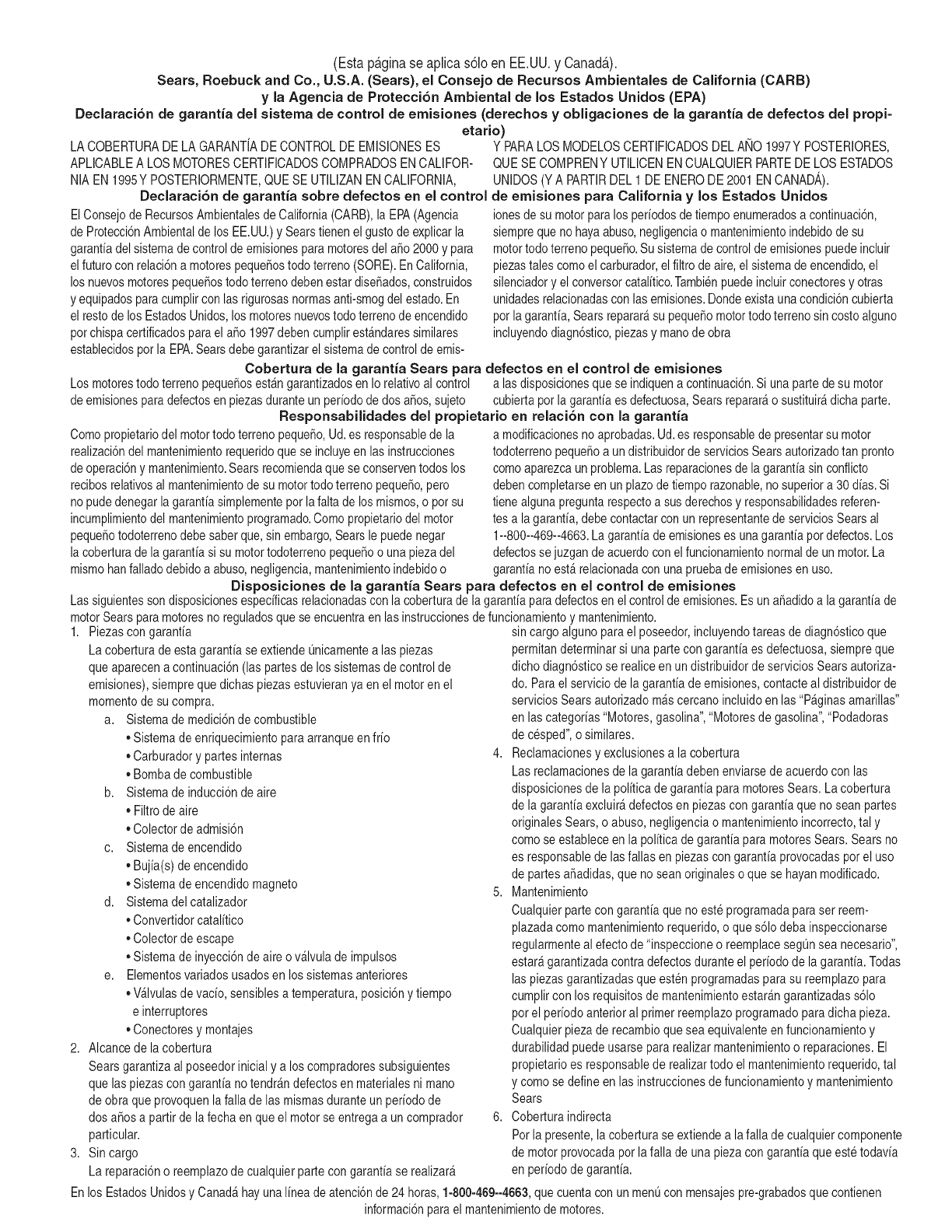
(Esta p_.ginase aplica s61oen EE.UU. y Canada.).
Sears, Roebuck and Co., U.S.A. (Sears), el Consejo de Recursos Arnbientales de California (CARB)
y la Agencia de Protecci6n Ambiental de los Estados Unidos (EPA)
Declaraci6n de garantia del sistema de control de emisiones (derechos y obligaciones de la garantia de defectos del propi=
etario)
LACOBERTURADELA GARANTJADE CONTROLDEEMISIONESES Y PARALOSMODELOSCERTIFICADOSDELANO 1997YPOSTERIORES,
APLICABLEA LOSMOTORESCERTIFICADOSCOMPRADOSENCALIFOR-
NIA EN1995YPOSTERIORMENTE,QUESE UTILIZANENCALIFORNIA,
Declaraci6n de garantJa sobre defectos en el control
ElConsejode RecursosAmbientalesdeCalifornia(CARB),la EPA(Agencia
deProtecci6nAmbientalde los EE.UU.)y Searstienen elgustode explicarla
garantiadel sistemade controlde emisionesparamotoresdel a_o2000y para
elfuturocon relaci6na motorespeque_ostodo terreno(SORE).En California,
losnuevosmotorespeque6ostodo terrenodebenestar dise_ados,construidos
yequipadosparacumplircon las rigurosasnormasanti-smogdel estado.En
el restode losEstadosUnidos,losmotoresnuevostodoterrenodeencendido
porchispacertificadosparael a_o 1997debencumplirest_ndaressimilares
establecidospot la EPA.Searsdebegarantizarel sistemade controlde emis-
QUESE COMPRENYUTILICENENCUALQUIERPARTEDELOS ESTADOS
UNIDOS(YA PARTIRDEL 1 DEENERODE 2001 ENCANADA).
de ernisiones para California y los Estados Unidos
ionesdesu motorparalosperiodosdetiempoenumeradosa continuaci6n,
siemprequenohayaabuso,negligenciao mantenimientoindebidode su
motortodoterrenopeque_o.Susistemade controldeemisionespuedeincluir
piezastalescomoel carburador,el filtrode aire,el sistemade encendido,el
silenciadoryel conversorcatalitico.Tambienpuedeincluirconectoresy otras
unidadesrelacionadascon las emisiones.Dondeexistaunacondici6ncubierta
porla garantia,Searsreparar_su peque6omotortodo terrenosin costoalguno
incluyendodiagn6stico,piezasy manodeobra
Cobertura de la garantJa Sears para defectos en el control de ernJsiones
Losmotorestodo terrenopeque6osest_ngarantizadosen Iorelativoal control alas disposicionesque se indiquena continuaci6n.Siuna partedesu motor
deemisionesparadefectosenpiezasduranteun periododedosa_os,sujeto cubiertapot la garanfiaesdefectuosa,Sears reparar_o sustituir_dichaparte.
ResponsabJlidades del propietario en relacibn con la garantia
Comopropietariodel motortodo terrenopeque_o,Ud.es responsabledela
realizaci6ndel mantenimientorequeridoquese incluyeen las instrucciones
deoperaci6ny mantenimiento.Searsrecomiendaquese conserventodoslos
recibosrelativosal mantenimientodesu motortodoterrenopeque_o,pero
nopudedenegarlagarantiasimplementeporla faltadelosmismos,o por su
incumplimientodel mantenimientoprogramatic.Comopropietariodel motor
peque_otodoterrenodebe saberque, sinembargo,Searsle puedenegar
la coberturade la garantiasi su motortodoterrenopeque6oo una piezadel
mismohanfalladodebidoa abuso,negligencia,mantenimientoindebidoo
a modificacionesno aprobadas.Ud.es responsabledepresentarsu motor
todoterrenopeque6oa undistribuidorde serviciosSearsautorizadotan pronto
comoaparezcaun problema.Lasreparacionesdela garantiasinconfiicto
debencompletarseen unplazodetiemporazonable,no superiora 30dias.Si
tienealgunapreguntarespectoa sus derechosy responsabilidadesreferen-
tes a lagarantia,debecontactarcon un representantede serviciosSearsal
1--800--469--4663.La garantiadeemisioneses unagarantiapordefectos.Los
defectossejuzgan deacuerdoconel funcionamientonormalde un motor.La
garantianoest_relacionadaconunapruebadeemisionesenuso.
Disposiciones de la garantJa Sears para defectos en el control de emisiones
Lassiguientessondisposicionesespecificasrelacionadascon la coberturade lagarantia paradefectosenel controldeemisiones.Es una_adidoa lagarantiade
motorSearsparamotoresnoreguladosque seencuentraen lasinstruccionesde funcionamientoy mantenimiento.
1. Piezascongarantia
Lacoberturade estagarantiase extiendeL]nicamentealas piezas
queaparecena continuaci6n(las partesde lossistemasdecontrolde
emisiones),siempreque dichaspiezasestuvieranya enel motoren el
momentode su compra.
a. Sistemademedici6nde combustible
•Sistemade enriquecimientoparaarranqueenfrio
•Carburadory partesinternas
•Bombade combustible
b. Sistemadeinducci6nde aire
•Filtrode aire
•Colectorde admisi6n
c. Sistemadeencendido
•Bujia(s)deencendido
•Sistemade encendidomagneto
d. Sistemadelcatalizador
•Convertidorcatalitico
•Colectorde escape
•Sistemade inyecci6ndeaire o v_lvulade impulsos
e. Elementosvariadosusadosen los sistemasanteriores
•Wlvulas de vacio,sensiblesa temperatura,posici6ny tiempo
e interruptores
•Conectoresy montajes
2. AIcancede la cobertura
Searsgarantizaal poseedorinicialya loscompradoressubsiguientes
que laspiezascongarantianotendr_ndefectosen materialesni mano
deobraque provoquenla falla delas mismasduranteunperiodo de
dosa6osa partirdela fechaen queel motorse entregaa uncomprador
particular.
3. Sin cargo
Lareparaci6no reemplazode cualquierpartecongarantiase realizar_
sin cargoalgunoparael poseedor,incluyendotareasdediagn6sticoque
permitandeterminarsi una partecon garantiaes defectuosa,siempreque
dichodiagn6sticose realiceen undistribuidorde serviciosSearsautoriza-
do. Parael serviciode lagarantiadeemisiones,contacteal distribuidorde
serviciosSearsautorizadom_scercanoincluidoen las"P_ginasamarillas"
en lascategorias"Motores,gasolina","Motoresdegasolina","Podadoras
de cesped",o similares.
4. Reclamacionesy exclusionesa la cobertura
Lasreclamacionesde lagarantiadebenenviarsedeacuerdo conlas
disposicionesdela politicade garantiaparamotoresSears.La cobertura
de la garantiaexcluir_defectosenpiezascon garantiaque noscan partes
originalesSears,o abuso,negligenciao mantenimientoincorrecto,tal y
como se estableceenla politica degarantiaparamotoresSears.Searsno
es responsablede lasfallas en piezascon garantiaprovocadaspor el uso
de partesaSadidas,que noscan originaleso quese hayan modificado.
5. Mantenimiento
Cualquierpartecongarantiaque no esteprogramadaparaserreem-
plazadacomomantenimientorequerido,o que s61odeba inspeccionarse
regularmenteal efectode "inspeccioneo reemplacesegL]nsea necesario",
estar_garantizadacontradefectosduranteel periodode la garantia.Todas
laspiezasgarantizadasque esten programadasparasu reemplazopara
cumplircon los requisitosde mantenimientoestar_ngarantizadass61o
porel periodoanterioral primerreemplazoprogramaticparadicha pieza.
Cualquierpiezade recambioqueseaequivalenteenfuncionamientoy
durabilidadpuedeusarsepararealizarmantenimientoo reparaciones.El
propietarioes responsablede realizartodo elmantenimientorequerido,tal
y comose defineen las instruccionesdefuncionamientoy mantenimiento
Sears
6. Coberturaindirecta
Porla presente,la coberturase extiendea lafallade cualquiercomponente
de motorprovocadapor lafalla de unapiezacon garantiaqueestetodavia
en periododegarantia.
Enlos EstadosUnidosy Canad_hay unalineade atenci6nde 24 horas,1-800-469--4GG3,quecuentaconunmenL]conmensajespre-grabadosque contienen
informaci6nparael mantenimientodemotores.
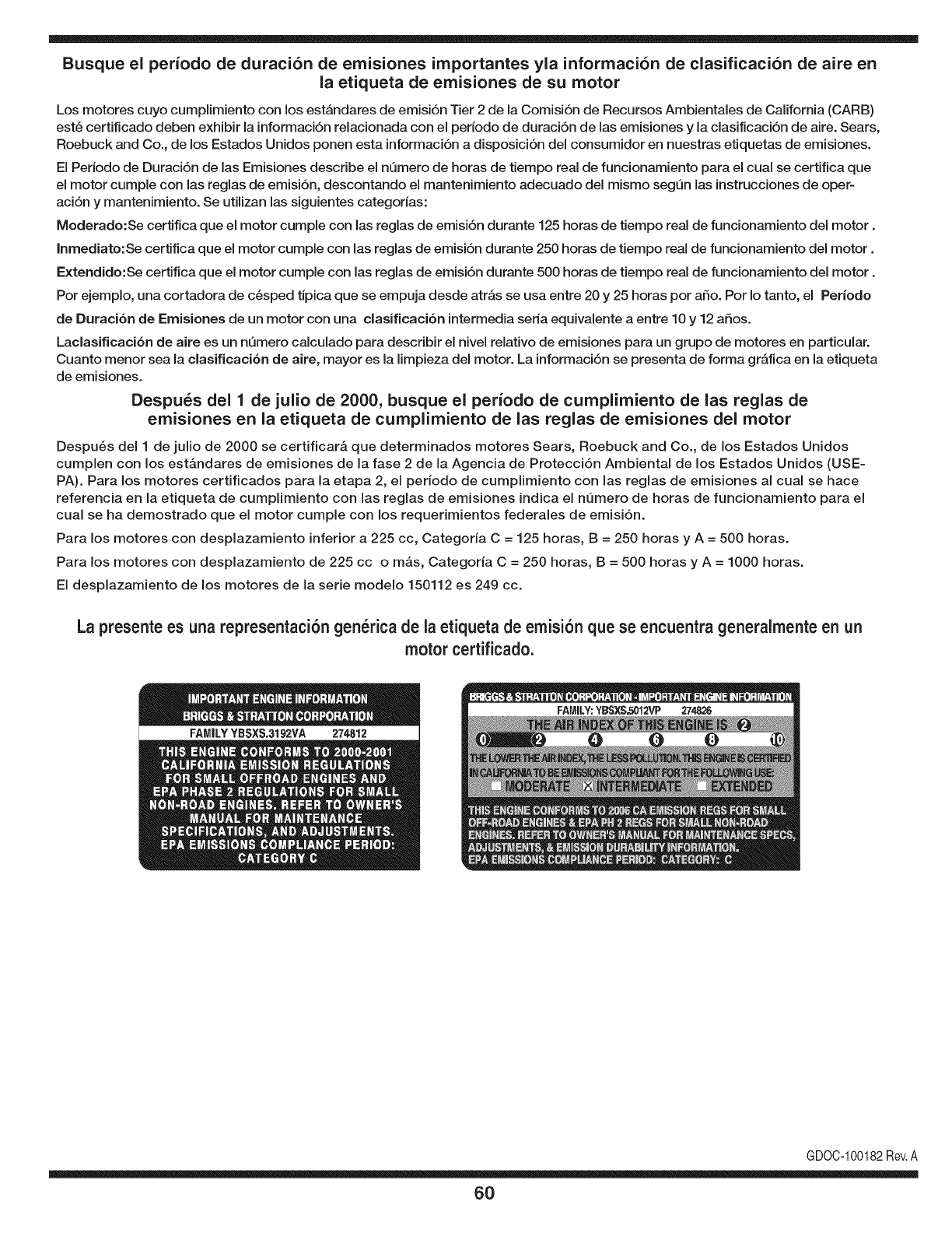
Busque el periodo de duraci6n de emisiones importantes yla informaci6n de clasificaci6n de aire en
la etiqueta de emisiones de su motor
Los motores cuyo cumpiimiento con los estAndares de emisi6n Tier 2 de la Comisi6n de Recursos Ambientales de California (CARB)
est6 certificado deben exhibir la informaci6n relacionada con el perJodo de duraci6n de las emisiones y la clasificaci6n de aire. Sears,
Roebuck and Co., de los Estados Unidos ponen esta informaci6n a disposici6n deJ consumidor en nuestras etiquetas de emisiones.
El Periodo de Duraci6n de las Emisiones describe el nQmero de horas de tiempo real de funcionamiento para el cual se certifica que
el motor cumple con las reglas de emisi6n, descontando el mantenimiento adecuado deJ mismo segQn las instrucciones de oper-
aci6n y mantenimiento. Se utilizan las siguientes categorias:
Moderado:Se certifica que el motor cumpie con las reglas de emisi6n durante 125 horas de tiempo real de funcionamiento deJmotor.
Inmediato:Se certifica que el motor cumple con las reglas de emisi6n durante 250 horas de tiempo real de funcionamiento deJ motor.
Extendido:Se certifica que el motor cumple con las reglas de emisi6n durante 500 horas de tiempo real de funcionamiento deJmotor.
Por ejemplo, una cortadora de c6sped tJpica que se empuja desde atrAs se usa entre 20 y 25 horas por afio. Por Io tanto, el Periodo
de Duraci6n de Emisiones de un motor con una clasificaci6n intermedia seria equivalente a entre 10 y 12 afios.
Laclasificaci6n de aJre es un nQmero calculado para describir eJnivel reiativo de emisiones para un grupo de motores en particular.
Cuanto menor sea Jaclasificaci6n de aire, mayor es JaJimpieza deJmotor. La informaci6n se presenta de forma gr&fica en Jaetiqueta
de emisiones.
Despu_s del 1 de julio de 2000, busque el periodo de cumplimiento de las reglas de
emisiones en la etiqueta de cumplimiento de las reglas de emisiones del motor
Despu_s deJ 1 de julio de 2000 se certificar_, que determinados motores Sears, Roebuck and Co., de los Estados Unidos
cumpien con los estAndares de emisiones de la fase 2 de la Agencia de Protecci6n Ambiental de los Estados Unidos (USE-
PA). Para los motores certificados para la etapa 2, el periodo de cumpiimiento con las reglas de emisiones al cual se hace
referencia en la etiqueta de cumpiimiento con las reglas de emisiones indica el nQmero de horas de funcionamiento para el
cuaJ se ha demostrado que el motor cumpie con los requerimientos federales de emisi6n.
Para los motores con desplazamiento inferior a 225 cc, Categoria C = 125 horas, B = 250 horas y A = 500 horas.
Para los motores con desplazamiento de 225 cc o mAs, Categoria C = 250 horas, B = 500 horas y A = 1000 horas.
El despiazamiento de los motores de la serie modelo 150112 es 249 cc.
La presente es una representaci6n gen_rica de la etiqueta de emisi6n que se encuentra generaimente en un
motor certificado.
FAMILYYBSXS.3192VA 274812
GDOC-100182Rev.A
60
Felicitacionespor haberrealizadounaadquisici6ninteligente.El
productoCraftsman@queha adquiridoest_dise_adoy fabricado
parabrindarrnuchosa_osde funcionarnientoconfiable.Perocorno
todoslos productosa vecespuederequerirde reparaciones.Esen
esernornentocuandoel disponerde unAcuerdode protecci6npara
reparacionesle puedeahorrardineroy problernas.
A continuaci6nsedetallanlos puntosincluidosenel Acuerdo:
• Servicio experto prestadopornuestros10,000especialistasen
reparacionesprofesionales
• Servicio iJirnitadosincargoparalaspiezasy la rnanodeobraen
todaslas reparacionescubiertas
• Reemplazodel productosi noes posiblerepararel producto
cubierto
• Descuento de 10%del precionormaldel servicioy delas piezas
relacionadascon el rnisrnoqueno est6ncubiertasporel acuerdo;
adern&s,10%del precionormalde laverificaci6nde rnanten-
irnientoprevenfivo
•Ayudar_pidapottel_fono- IoIlarnarnosResoluci6nR@ida- el
apoyotelef6nicode unCharnuscaal representante.Pienseen
nosotroscornoel manual"de undue_ohablador."
Unavezadquiridoel Acuerdo,puedeprograrnarel serviciocon
tan s61orealizarunaIlarnadatelef6nica.PuedeIlarnarencualquier
rnornentodeldia o dela nocheo prograrnarun servicioen linea.
Searsdisponedern_.sde 10.000especialistasen reparaciones
profesionalesquetienenaccesoa rn_.sde4.5 rnillonesdepiezasy
accesoriosde buenacalidad.Estees eltipo de profesionalisrnoen
el quepuedeconfiarparaquele ayudea prolongarlavida Qtildel
productorecienternenteadquiridoenlos a_osporvenir,iAdquierahoy
suacuerdodeprotecci6nparareparaciones!
Seaplican determinadaslimitacionesy exclusiones.Paraobtener
informaci6nadicional y preciosIlameal 1-800-827-6655.
Servicio de instalacibnde Sears
Sideseasolicitarla instalaci6nprofesionalde Searsde aparatos
dorn6sticos,dispositivosparaabrirportones,calentadoresde aguay
otrosarticulosdorn6sticosirnportantes,enlos EstadosUnidosIlarne
al 1-800-4-MY-HOME®.
61

62

63

Your Home
For expert troubleshooting and home solutions advice:
www.managemyhome.com
For repair - in your home - of all major brand appliances,
lawn and garden equipment, or heating and cooling systems,
no matter who made it, no matter who sold it!
For the replacement parts, accessories and
owner's manuals that you need to do-it-yourself.
For Sears professional installation of home appliances
and items like garage door openers and water heaters.
1-800-4-MY-HOME ®(1-800-469-4663)
Call anytime, day or night (U.S.A. and Canada)
www.sears.com www.sears.ca
Our Home
For repair of carry-in items like vacuums, lawn equipment,
and electronics, call anytime for the location of your nearest
Sears Parts & Repair Service Center
1-800-488-1222 (U.S.A.) 1-800-469-4663 (Canada)
www.sears.com www.sears.ca
To purchase a protection agreement on a product serviced by Sears:
1-800-827-6655 (U.S.A.) 1-800-361-6665 (Canada)
Para pedir servicio de reparaci6n
a domicilio, y para ordenar piezas:
1-888-SU-HOGAR ®
(1-888-784-6427)
Au Canada pour service en fran£ais:
1-800-LE-FOYER M°
(1-800-533-6937)
www.sears.ca
® Registered Trademark /TMTrademark /SM Service Mark of Sears Brands, LLC
SM
® Marca Registrada /TMMarca de F&brica /Marca de Servicio de Sears Brands, LLC
MCMarque de commerce /MDMarque depos6e de Sears Brands, LLC © Sears Brands, LLC
