MTD 24A 462G729 User Manual CHIPPER/SHREDDER Manuals And Guides 1108458L
User Manual: MTD 24A-462G729 24A-462G729 MTD CHIPPER/SHREDDER - Manuals and Guides View the owners manual for your MTD CHIPPER/SHREDDER #24A462G729. Home:Lawn & Garden Parts:MTD Parts:MTD CHIPPER/SHREDDER Manual
Open the PDF directly: View PDF ![]() .
.
Page Count: 20
Safety • Assembly • Operation • Tips & Techniques • Maintenance • Troubleshooting • Parts Lists • Warranty
OF AOAL
/
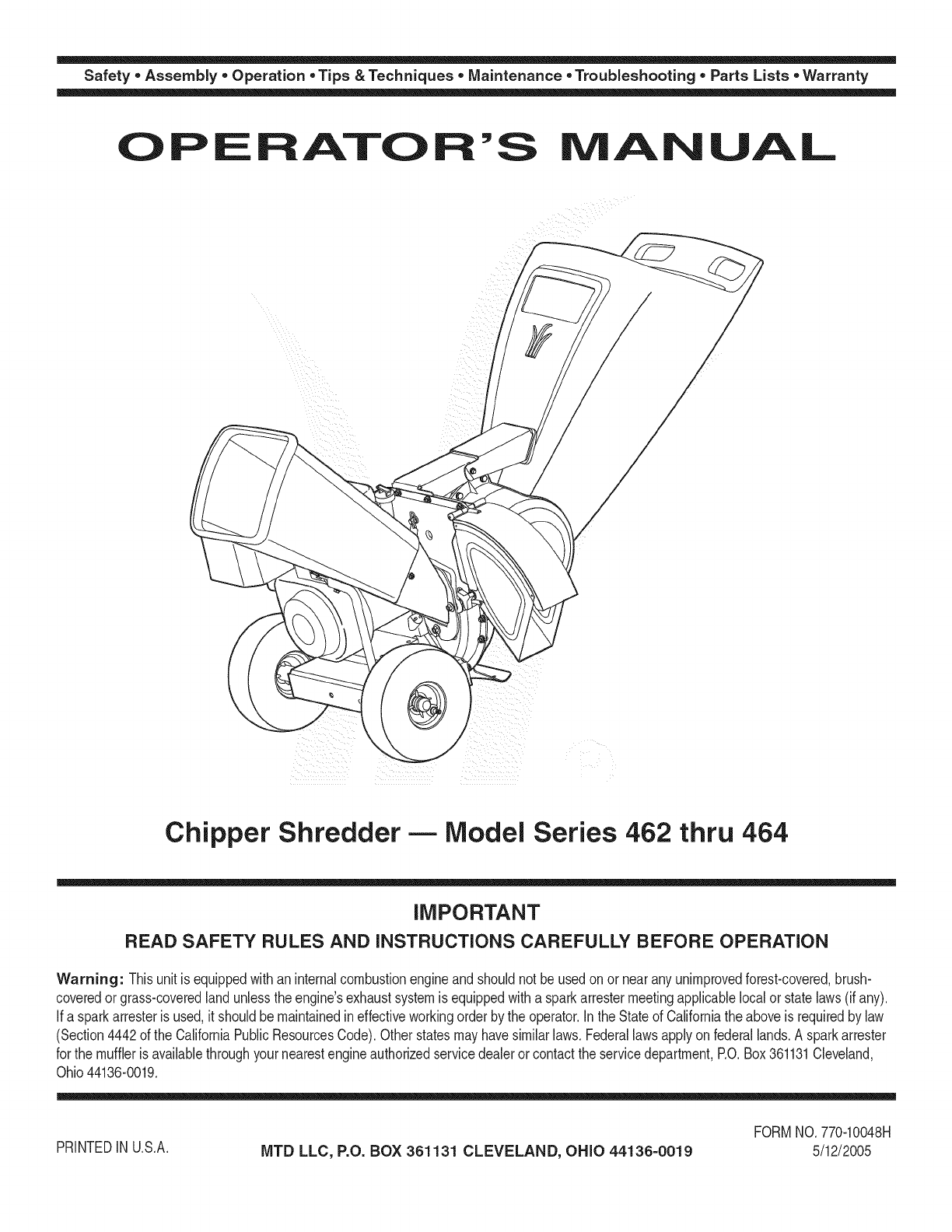
Chipper Shredder- Model Series 462 thru 464
iMPORTANT
READ SAFETY RULES AND iNSTRUCTiONS CAREFULLY BEFORE OPERATION
Warning: Thisunit is equippedwithaninternalcombustionengineandshouldnot beusedon or nearany unimprovedforest-covered,brush-
coveredor grass-coveredlandunlesstheengine'sexhaustsystemis equippedwitha sparkarrestermeetingapplicablelocalor statelaws(if any).
If a sparkarresteris used,it shouldbemaintainedineffectiveworkingorderby the operator.In theStateof Californiathe aboveis requiredbylaw
(Section4442of the CaliforniaPublicResourcesCode).Otherstatesmayhavesimilarlaws.Federallawsapplyonfederallands.A sparkarrester
for the muffleris availablethroughyour nearestengineauthorizedservicedealeror contactthe servicedepartment,RO.Box361131Cleveland,
Ohio44136-0019.
PRINTEDIN U.S.A. MTD LLC, P.O. BOX 361131 CLEVELAND, OHIO 44136-0019
FORMNO.770-10048H
5/12/2005
This Operator's Manual is an important part of your new chipper shredder, it will help you assemble, pre-
pare and maintain the unit for best performance. Please read and understand what it says.
Table of Contents
Customer Support .............................................. 2
Safety Labels ...................................................... 3
Safe Operation Practices ................................... 4
Setting UpYour Chipper Shredder .................... 6
Operating Your Chipper Shredder ..................... 8
Maintaining Your Chipper Shredder ................ 10
Troubleshooting ................................................ 12
Parts List ........................................................... 14
Warranty ............................................ Back Cover
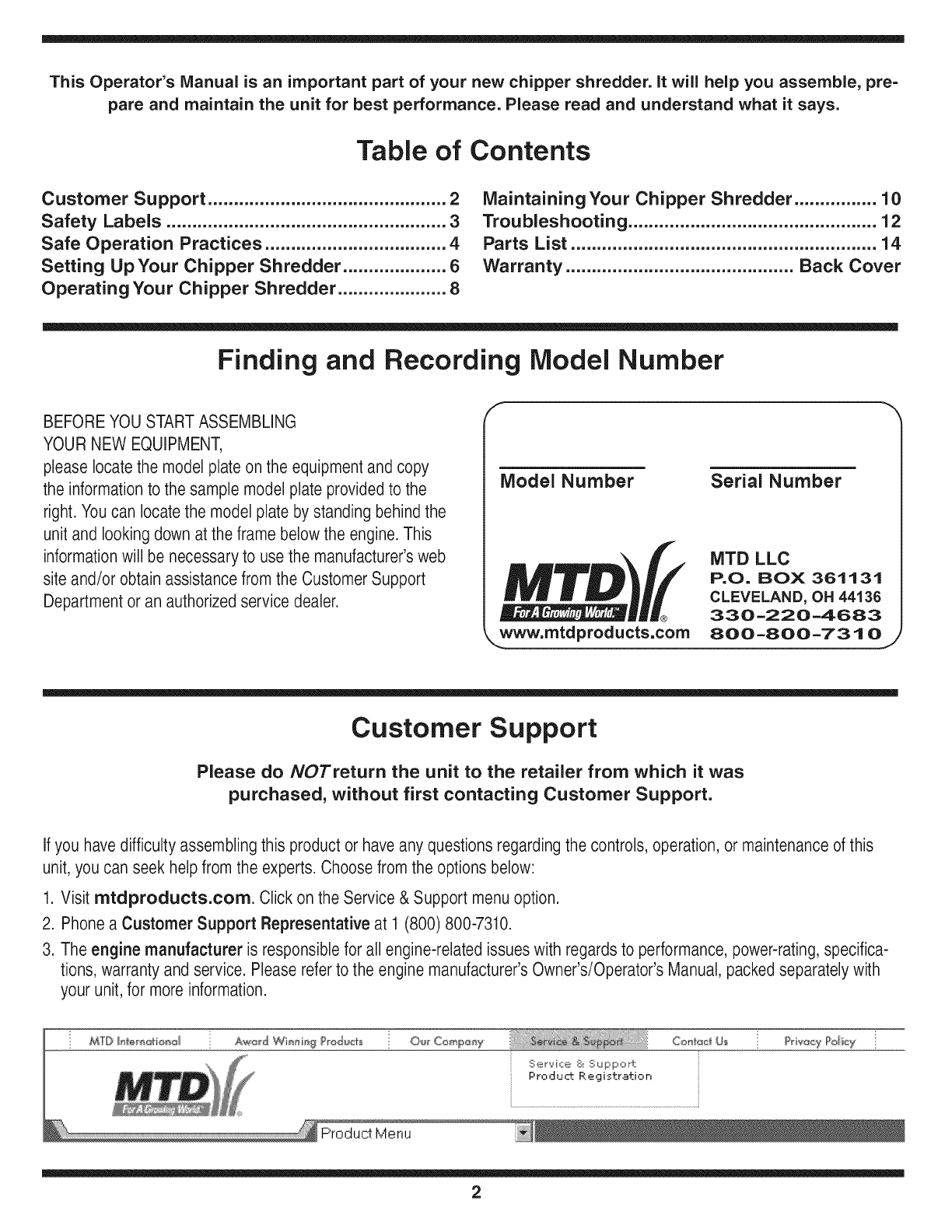
Finding and Recording Model Number
BEFOREYOU STARTASSEMBLING
YOUR NEW EQUIPMENT,
pleaselocate the model plateon the equipment and copy
the informationto the sample model plate providedto the
right. Youcan locate the model plate by standing behind the
unit and looking down at the frame below the engine. This
informationwill be necessary to use the manufacturer'sweb
site and/or obtain assistance from the Customer Support
Department or an authorizedservice dealer.
f *x,
Model Number
®
www.mtdproducts,com
Serial Number
MTD LLC
P.O. BOX 361131
CLEVELAND, OH 44136
330 -220 -4683
800-800-7310 J
Customer Support
Please do NOTretum the unit to the retailer from which it was
purchased, without first contacting Customer Support.
Ifyou havedifficulty assembling this product or haveany questionsregarding the controls, operation, or maintenanceof this
unit, you can seek helpfrom the experts. Choose from the options below:
1. Visit mtdproducts.com. Click on the Service & Support menu option.
2. Phone a Customer Support Representative at 1 (800) 800-7310.
3. The engine manufacturer is responsible for all engine-related issues with regards to performance,power-rating,specifica-
tions, warranty and service. Pleaserefer to the engine manufacturer'sOwner's/Operator's Manual, packedseparately with
your unit,for more information.
MTD Hin_r_oti®d A_wJ_d Wi_n i_g ?rod_t_ O'_r Comp_y Con_@_z_Us
Ser,oqce & Suppo ±
Product. Registration
?rba_y Policy
2
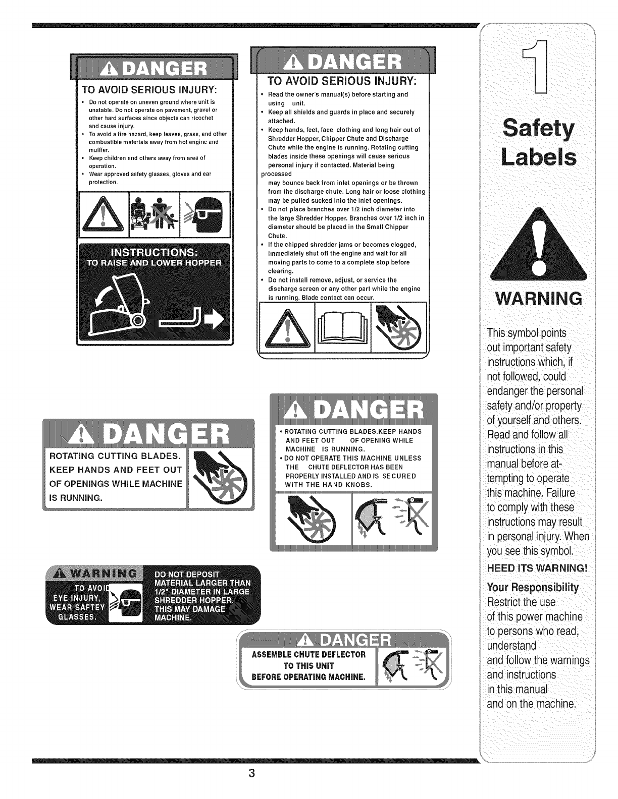
TO AVOID SERIOUS iNJURY:
• Do not operate on uneven ground where unit is
unstable, Do not operate on pavement, gravel or
other hard surfaces since objects can ricochet
and cause injury,
• To avoid a fire hazard, keep leaves, grass, and other
combustible materials away from hot engine and
muffler,
• Keep children and others away from area of
operation,
• Wear approved safety glasses, gloves and ear
protection.
ROTATING CUTTING BLADES.
TO AVOID SERIOUS iNJURY:
• Read the owner's manual(s) before starting and
using unit,
• Keep all shields and guards in place and securely
attached.
• Keep hands, feet, face, clothing and long hair out of
Shredder Hopper, Chipper Chute and Discharge
Chute while the engine is running, Rotating cutting
blades inside these openings will cause serious
personal injury if contacted. Material being
processed
may bounce back from inlet openings or be thrown
from the discharge chute. Long hair or loose clothing
may be pulled sucked into the inlet openings.
• Do not place branches over 1/2 inch diameter into
the large Shredder Hopper. Branches over 1/2 inch in
diameter should be placed in the Small Chipper
Chute.
• If the chipped shredder jams or becomes clogged,
immediately shut off the engine and wait for all
moving parts to come to a complete stop before
clearing.
• Do not install remove, adjust, or service the
discharge screen or any other part while the engine
is running. Blade contact can occur.
J
KEEP HANDS AND FEET OUT
OF OPENINGS WHILE MACHINE
iS RUNNING.
• ROTATING CUTTING BLADES.KEEP HANDS
AND FEET OUT OF OPENING WHILE
MACHINE iS RUNNING.
DO NOT OPERATE THiS MACHINE UNLESS
THE CHUTE DEFLECTOR HAS BEEN
PROPERLY iNSTALLED AND IS SECURED
WITH THE HAND KNOBS.
3
iil _I ii_ _ i _iii _! i _ _ii_ ii
WARNING
This symbolpoints
out importantsafety
instructionswhich, if
not followed,could
endangerthe personal
safetyand/or property
of yourselfandothers.
Readandfollowall
instructionsinthis
manualbeforeat-
temptingto operate
this machine.Failure
to complywiththese
instructionsmay result
in personalinjury.When
you see this symbol.
HEED ITS WARNING!
Your Responsibility
Restrictthe use
of this power machine
to persons who read,
understand
and follow the warnings
and instructions
in this manual
and onthe machine.
WARNING
This symbolpoints
out importantsafety
instructionswhich, if
notfollowed,could
endangerthe personal
i safetyand/or property
I ofyourselfand others.
Readandfollowall
instructionsinthis
manualbeforeat-
temptingto operate
i this machine. Failure
I to complywiththese
instructionsmay result
i in personalinjury.When
you see this symbol.
i HEED ITS WARNING!
Your Responsibility
Restrictthe use
of this power machine
to personswho read,
_understand
ane followthe warnings
and instructions
inthis manual
and on the machine.
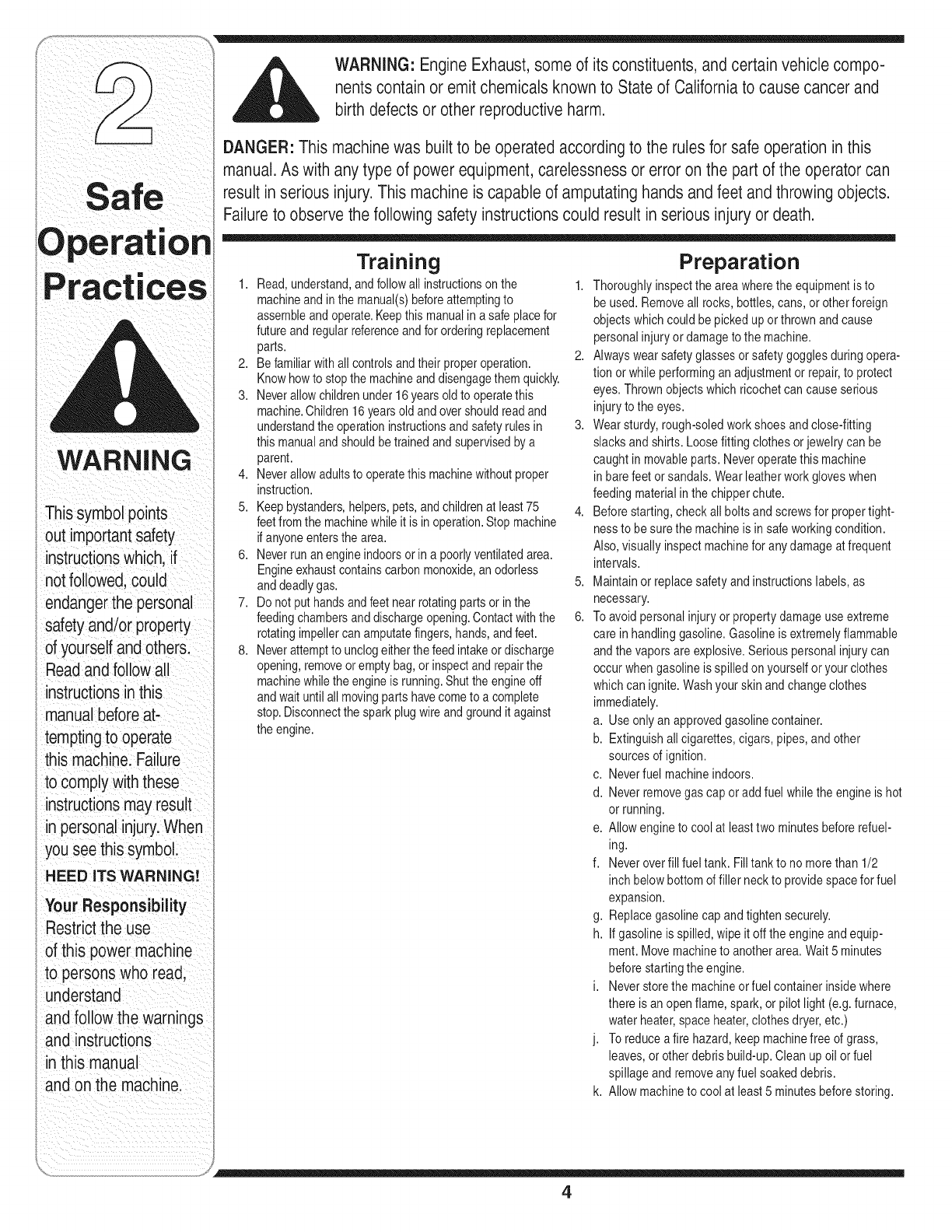
WARNING: Engine Exhaust,some of its constituents, andcertain vehicle compo-
nentscontain or emit chemicals knownto Stateof Californiato cause cancer and
birth defects or other reproductiveharm.
DANGER: This machinewas built to be operatedaccording to the rulesfor safe operationin this
manual.As with any type of power equipment,carelessnessor error on the part of the operator can
result in serious injury.This machine is capable of amputating hands andfeet andthrowing objects.
Failureto observe the followingsafety instructionscould result in serious injury or death.
Training
1. Read,understand,andfollowall instructionsonthe 1.
machineandin themanual(s)beforeattemptingto
assembleand operate.Keepthis manualina safe placefor
futureandregularreferenceandfor orderingreplacement
parts. 2.
2. Befamiliarwithall controlsandtheir properoperation.
Knowhowto stopthe machineanddisengagethem quickly.
3. Neverallowchildrenunder16yearsoldto operatethis
machine.Children16yearsold andovershouldreadand
understandtheoperationinstructionsand safetyrulesin 3.
this manualand shouldbe trainedand supervisedbya
parent.
4. Neverallowadultsto operatethis machinewithoutproper
instruction.
5. Keepbystanders,helpers,pets,andchildrenat least 75 4.
feetfromthe machinewhileit is in operation.Stop machine
ifanyoneentersthearea.
6. Neverrun an engineindoorsorin a poorlyventilatedarea.
Engineexhaustcontainscarbonmonoxide,an odorless
anddeadlygas. 5.
7. Donot puthandsandfeet nearrotatingparts or inthe
feedingchambersand dischargeopening.Contactwiththe 6.
rotatingimpellercanamputatefingers,hands,andfeet.
8. Neverattemptto unclogeitherthefeed intakeor discharge
opening,removeoremptybag, orinspectandrepairthe
machinewhilethe engineis running.Shuttheengineoff
andwaituntil allmovingparts havecometo a complete
stop.Disconnectthe sparkplugwire andgroundit against
theengine.
Preparation
Thoroughlyinspectthe areawherethe equipmentisto
beused. Removeall rocks,bottles,cans,or otherforeign
objectswhichcouldbe pickedupor thrownandcause
personalinjuryor damageto the machine.
Alwayswearsafetyglassesor safetygogglesduringopera-
tionor whileperforminganadjustmentor repair,to protect
eyes.Thrownobjectswhich ricochetcancause serious
injuryto the eyes.
Wearsturdy,rough-soledworkshoesand close-fitting
slacksandshirts. Loosefittingclothesor jewelrycan be
caughtin movableparts.Neveroperatethis machine
in barefeet or sandals.Wearleatherworkgloveswhen
feedingmaterialin thechipperchute.
Beforestarting,checkallbolts and screwsfor propertight-
nessto besurethe machineis in safeworkingcondition.
Also,visuallyinspectmachinefor any damageat frequent
intervals.
Maintainor replacesafetyandinstructionslabels,as
necessary.
Toavoidpersonalinjuryor propertydamageuse extreme
care inhandlinggasoline.Gasolineis extremelyflammable
andthe vaporsare explosive.Seriouspersonalinjurycan
occurwhengasolineis spilledonyourselforyour clothes
whichcan ignite.Washyour skinand changeclothes
immediately.
a. Useonly an approvedgasolinecontainer.
b. Extinguishall cigarettes,cigars, pipes,andother
sourcesof ignition.
c. Neverfuel machineindoors.
d. Neverremovegascap oradd fuel whilethe engineis hot
or running.
e. Allowengineto coolat leasttwo minutesbeforerefuel-
ing.
f. Neveroverfill fueltank. Filltankto nomorethan 1/2
inch belowbottomof filler neckto providespacefor fuel
expansion.
g. Replacegasolinecap andtightensecurely.
h. If gasolineis spilled,wipe itoff theengineand equip-
ment.Movemachineto anotherarea.Wait5 minutes
beforestartingtheengine.
i. Neverstorethe machineorfuel containerinsidewhere
there is an openflame, spark,or pilot light (e.g.furnace,
waterheater,spaceheater,clothesdryer,etc.)
j. Toreducea fire hazard,keepmachinefree of grass,
leaves,or otherdebris build-up.Cleanup oilor fuel
spillageand removeanyfuel soakeddebris.
k. Allowmachineto cool at least5 minutesbeforestoring.
4
Operation
1. Donot puthands andfeet nearrotatingpartsor in the
feedingchambersand dischargeopening.Contactwith the
rotatingimpellercanamputatefingers, hands,andfeet.
2. Beforestartingthe machine,makesurethe chipperchute,
feed intake,and cuttingchamberare empty andfree of all
debris.
3. Thoroughlyinspectall materialto be shreddedand remove
any metal,rocks,bottles, cans,orotherforeignobjects
which could causepersonalinjuryor damageto the
machine.
14.f it becomesnecessaryto pushmaterialthroughthe
shredderhopper,usea smalldiameterstick. Do notuse
your hands orfeet.
15.f the impellerstrikesa foreignobject or ifyour machine
should start makingan unusualnoiseor vibration,
immediatelyshuttheengineoff.Allow the impellerto come
to a completestop.Disconnectthe sparkplugwire,ground
itagainstthe engineandperformthe followingsteps:
a. Inspectfor damage.
b. Repairorreplaceany damagedparts.
c. Checkfor anyloosepartsand tightento assure
continuedsafeoperation.
6. Donotallow an accumulationof processedmaterialto build
upinthe dischargearea.Thiscan preventproperdischarge
and result in kickbackof materialthroughthefeed opening.
7. Donotattemptto shred orchip materiallargerthan
specifiedonthe machineor inthis manual.Personalinjury
or machinedamagecouldresult.
8. Neverattemptto unclogeitherthe feed intakeordischarge
openingwhilethe engineis running.Shutthe engineoff,
wait until all movingparts havestopped,disconnectthe
spark plugwire andground it againsttheenginebefore
clearingdebris.
9. Neveroperatewithoutthe shredderhopper,chipperchute,
or chute deflectorproperlyattachedto the machine.Never
emptyor changedischargebagwhiletheengineis running.
10.Keepall guards,deflectorsand safetydevicesin placeand
operatingproperly.
11.Keepyourface andbody backand totheside ofthe chipper
chute whilefeedingmaterialintothe machineto avoid
accidentalkickbackinjuries.
12.Neveroperatethis machinewithoutgoodvisibility or light.
13.Donotoperatethis machineon a paved,gravelor non-level
surface.
14.Donotoperatethis machinewhile underthe influenceof
alcohol ordrugs.
15.Mufflerandenginebecomehotandcan causea burn.Do
nottouch.
16.Neverpickup or carrymachinewhilethe engineis running.
Maintenance & Storage
1. Nevertamper withsafetydevices.Checktheir proper
operationregularly.
2. Checkbolts and screwsfor propertightnessat frequent
intervalsto keepthe machinein safe workingcondition.
Also,visuallyinspectmachinefor anydamageand repair,if
needed.
3. Beforecleaning,repairing,or inspecting,stopthe engine
andmakecertainthe impellerand all movingparts have
stopped.Disconnectthe sparkplugwire and groundit
againsttheengineto preventunintendedstarting.
4. Do notchangethe enginegovernorsettingsor overspeed
theengine.The governorcontrolsthemaximumsafe
operatingspeed of theengine.
5. Maintainor replacesafetyandinstructionlabels,as neces-
sary.
6. Followthis manualforsafe loading,unloading,transporting,
andstorageof this machine.
7. Neverstorethe machineorfuel containerinsidewhere
thereis an openflame, sparkor pilot lightsuch as a water
heater,furnace,clothesdryer,etc.
8. Alwaysreferto theoperator'smanualfor properinstructions
onoff-seasonstorage.
9. If thefueltank has to bedrained,dothis outdoors.
10.Observeproperdisposallawsandregulationsfor gas,oil,
etc. to protectthe environment.
Do not modify engine
Toavoidseriousinjuryordeath,donot modifyengineinany
way.Tamperingwiththegovernorsettingcan leadto a runaway
engineandcauseit to operateat unsafespeeds.Nevertamper
withfactorysettingof enginegovernor.
Notice regarding Emissions
Engineswhichare certifiedto complywithCaliforniaandfederal
EPAemissionregulationsfor SORE(SmallOff RoadEquipment)
arecertifiedto operateonregularunleadedgasoline,and may
includethefollowingemissioncontrolsystems:EngineModifica-
tion(EM)andThreeWayCatalyst(TWO)ifso equipped.
Your Responsibility
Restrictthe useof this powermachineto personswho read,un-
derstandand followthe warningsand instructionsin this manual
andon the machine.
5
Operation
WARNING
This symbol points
out importantsafety
instructions, which if
not followed,could
endanger the personal
safety and/or property
of yourself and others.
Readand followall
instructions inthis man-
ual before attempting to
operate this machine.
Failureto comply with
these instructionsmay
result in personal injury.
When you see this
symbol.
HEED iT S WARNING!
YourResponsibility
Restrictthe use
of this power machine
to personswho read.
understand
and followthe warnings
and instructions
in this manua
and on the machine.
iMPORTANT
Thisunitis shipped
without gasoline or
oil inthe engine.Be
certain to service
enginewith gasoline
and oil as instructed
inthe separateengine
manual before operat-
ingyour machine.
NOTE:All references in
this manualto the left
or right side of the chip-
per shredderis from
the operating position
only. Exceptions.ifany,
will be specified.
Figure 1
Figure 2
j {
/j /'
Figure 3
iMPORTANT:Thisunit isshippedwithoutgasolineoroil
in theengine.Becertainto serviceenginewithgasoline
andoilas instructedinthe separateenginemanual
beforeoperatingyour machine.
Loose Parts In Carton
a. HopperAssembly d. Bag
b. ChuteDeflector e. SafetyGlasses
c. ChipperChute f. EngineOil
Attaching The Hopper
Assembly
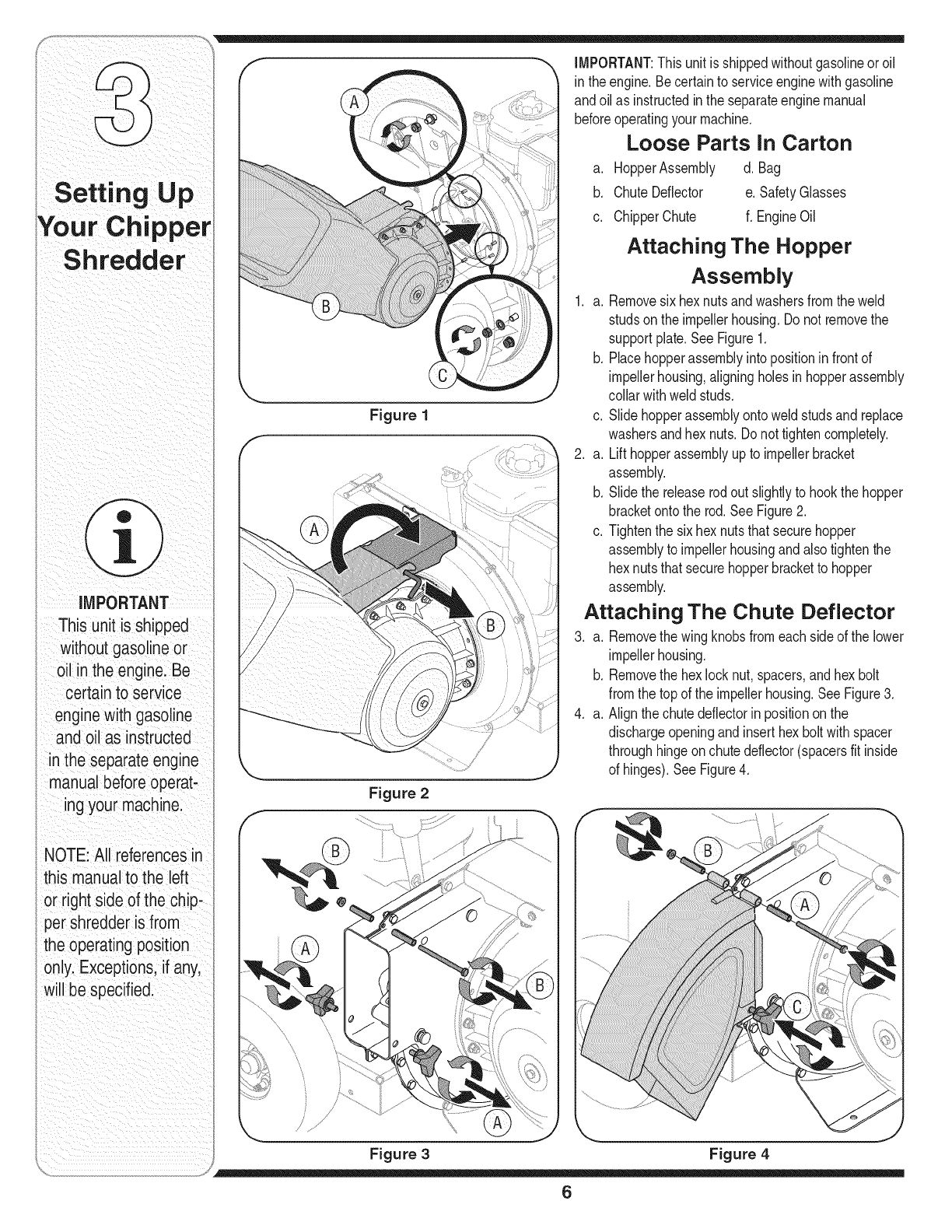
1. a. Removesixhexnutsandwashersfromthe weld
studsonthe impellerhousing.Donot removethe
supportplate.SeeFigure1.
b. Placehopperassemblyinto positioninfrontof
impellerhousing,aligningholesinhopperassembly
collarwithweldstuds.
c. Slidehopperassemblyontoweld studsand replace
washersandhex nuts.Donot tightencompletely.
2. a. Lift hopperassemblyupto impellerbracket
assembly.
b. Slidethe releaserodout slightlyto hookthe hopper
bracketontothe rod.SeeFigure2.
c. Tightenthe sixhexnutsthatsecurehopper
assemblyto impellerhousingandalsotightenthe
hexnutsthatsecurehopperbracketto hopper
assembly.
Attaching The Chute Deflector
3. a. Removethe wing knobsfromeachsideof the lower
impellerhousing.
b. Removethe hexlocknut,spacers,andhexbolt
fromthe top of the impellerhousing.SeeFigure3.
4. a. Alignthechutedeflectorin positiononthe
dischargeopeningandinserthexbolt withspacer
throughhingeonchutedeflector(spacersfit inside
of hinges).See Figure4.
Figure 4
6
b. Placesecondspaceroverhex bolt insideother
hingeandsecurewithhex locknut.
c. Securebothsidesof chutedeflectorto impeller
housingusingwingknobspreviouslyremoved.
Attaching The Chipper Chute
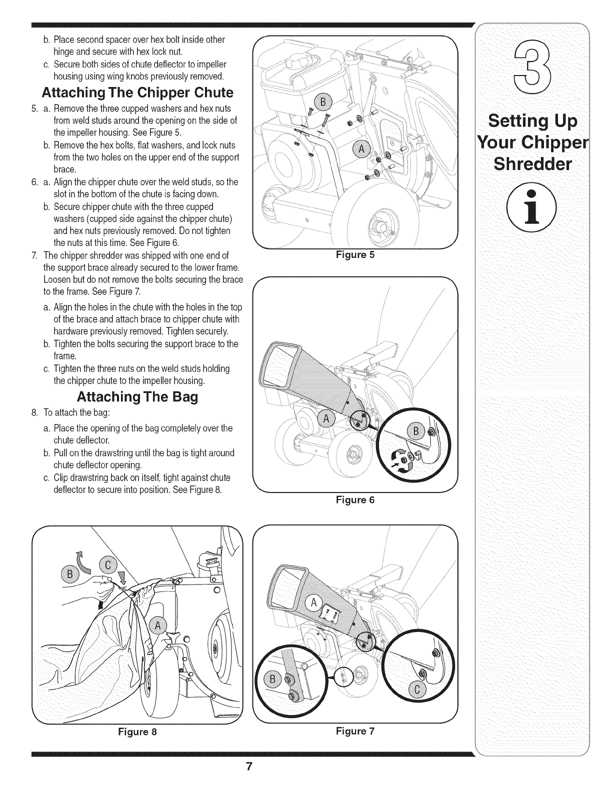
5. a. Removethe threecuppedwashersand hexnuts
fromweldstudsaroundthe openingonthe side of
the impellerhousing.SeeFigure5.
b. Removethe hexbolts,flat washers,andlocknuts
fromthe twoholeson the upperendof the support
brace.
6. a. Alignthe chipperchuteoverthe weldstuds,sothe
slotinthe bottomof the chuteis facingdown.
b. Securechipperchutewiththe threecupped
washers(cuppedsideagainstthe chipperchute)
and hexnutspreviouslyremoved.Do nottighten
the nutsat thistime. SeeFigure6.
7. The chippershredderwasshippedwithoneendof
the supportbracealreadysecuredto the lowerframe.
Loosenbutdo not removethe boltssecuringthe brace
to the frame.SeeFigure7.
a. Alignthe holesin thechutewiththe holesinthe top
of the braceandattachbraceto chipperchutewith
hardwarepreviouslyremoved.Tightensecurely.
b. Tightenthe boltssecuringthe supportbraceto the
frame.
c. Tightenthe threenutsonthe weldstuds holding
the chipperchuteto the impellerhousing.
Attaching The Bag
8. Toattachthe bag:
a. Placethe openingof the bagcompletelyover the
chutedeflector.
b. Pullon the drawstringuntilthe bagis tightaround
chutedeflectoropening.
c. Clipdrawstringbackon itself,tightagainstchute
deflectorto secureintoposition.SeeFigure8.
.//
Figure 5
f/
/
/
i
/
i
i
/
/
/
/
/
/
/
/
/
i /
/ /
/
/
/
J
Figure 6
Figure 8 Figure 7
/
/
i
i
i s
/
Your Chipper
Sh redder
ii i _iI_ ii
7
WARNING
The operation of any
chipper shredder
can result inforeign
objects being thrown
intothe eyes, which
can damageyour
Ieyes severely.Always
iwear the safety
glasses provided
with this unit or eye
ishields before chip-
ping or shredding
and while performing
iany adjustmentsor
repairs.
IUse extreme care
when handling
gasoline.Gasolineis
iextremelyflammable
and the vaporsare
explosive. Never fuel
i the machine indoors
or while the engine
is hotor running.
; Extinguishcigarettes,
cigars, pipes and
other sources of
iignition.
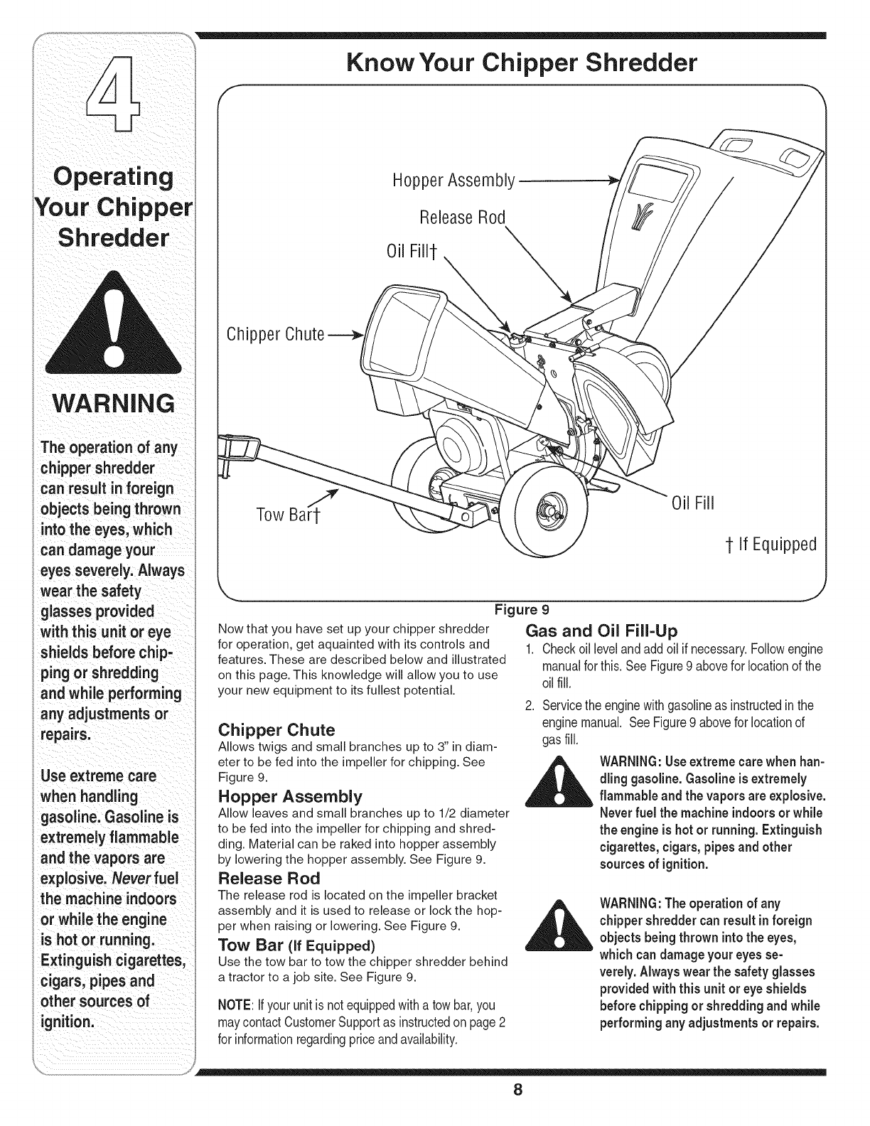
Know Your Chipper Shredder
Hopper Assembly
ReleaseRod
Oil Fill1-
Chipper
Tow Bart'_ @Oil Fill
1-If Equipped
Figure 9
Now that you have set up your chipper shredder
for operation, get aquainted with its controls and
features. These are described below and illustrated
on this page. This knowledge will allow you to use
your new equipment to its fullest potential.
Chipper Chute
Allows twigs and small branches up to 3" in diam-
eter to be fed into the impeller for chipping. See
Figure 9.
Hopper Assembly
Allow leaves and small branches up to 1/2 diameter
to be fed into the impeller for chipping and shred-
ding. Material can be raked into hopper assembly
by lowering the hopper assembly. See Figure 9.
Release Rod
The release rod is located on the impeller bracket
assembly and it is used to release or lock the hop-
per when raising or lowering. See Figure 9.
Tow Bar (if Equipped)
Use the tow bar to tow the chipper shredder behind
a tractor to a job site. See Figure 9.
NOTE:Ifyour unit isnotequippedwitha towbar,you
maycontactCustomerSupportas instructedon page2
for informationregardingpriceandavailability.
Gas and Oil Fill-Up
1. Check oil level and add oil if necessary. Follow engine
manual for this. See Figure 9 above for location of the
oil fill.
2. Servicethe enginewithgasolineas instructedinthe
enginemanual. SeeFigure9 abovefor locationof
gas fill.
WARNING:Useextreme carewhen han-
dling gasoline.Gasolineis extremely
flammable and the vapors areexplosive.
Neverfuel the machine indoorsor while
the engineis hotor running. Extinguish
cigarettes,cigars,pipesand other
sourcesof ignition.
WARNING:Theoperation of any
chippershreddercanresultinforeign
objectsbeingthrown intothe eyes,
which candamage youreyesse-
verely.Alwayswearthe safetyglasses
providedwith this unit or eye shields
before chippingor shreddingandwhile
performingany adjustments or repairs.
8
Starting Engine
_hlk ARNING:Neverrun the engine
indoorsor in a poorly ventilatedarea.
Engineexhaustcontainscarbonmonox-
ide,an odorlessand deadly gas.
1. Attachsparkplugwire to sparkplug.Makecertain
the metalcap on theend of the sparkplugis fastened
securelyoverthe metaltip onthe sparkplug.
2. Engines with choke lever:
Movechokeleveronengineto CHOKEposition.(A
warmenginemaynot requirechoking).
Engines with primer:
Primeengineas instructedinseparateenginemanual.
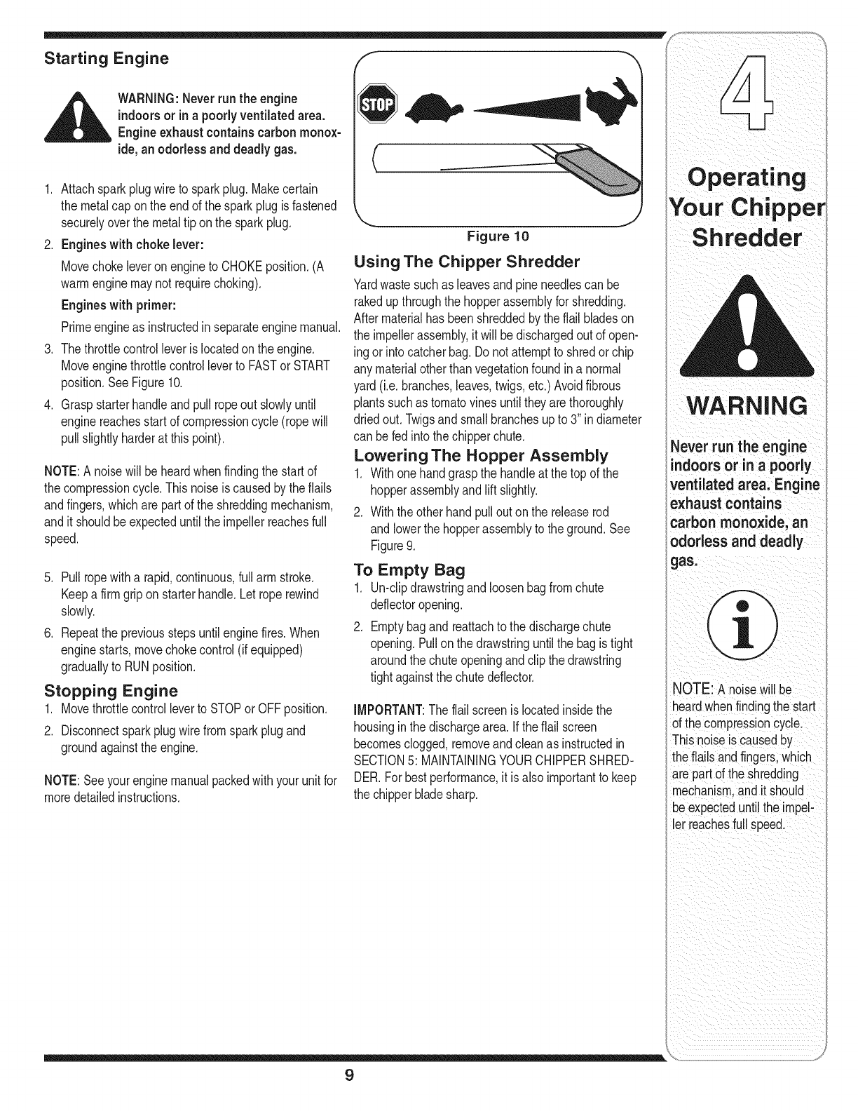
3. The throttlecontrolleveris locatedonthe engine.
Moveenginethrottlecontrolleverto FASTor START
position.SeeFigure10.
4. Graspstarterhandleand pullropeout slowlyuntil
enginereachesstart of compressioncycle(ropewill
pull slightlyharderat this point).
NOTE:A noisewill beheardwhenfindingthe start of
the compressioncycle.Thisnoiseis causedby theflails
andfingers,whichare partof the shreddingmechanism,
and it shouldbeexpecteduntilthe impellerreachesfull
speed.
5. Pullropewitha rapid,continuous,fullarm stroke.
Keepa firmgriponstarterhandle.Let roperewind
slowly.
6. Repeatthe previousstepsuntilenginefires.When
enginestarts,movechokecontrol(if equipped)
graduallyto RUNposition.
Stopping Engine
1. Movethrottlecontrolleverto STOPor OFFposition.
2. Disconnectsparkplugwirefromsparkplugand
groundagainstthe engine.
NOTE:Seeyourenginemanualpackedwithyourunitfor
moredetailedinstructions.
Figure 10
Using The Chipper Shredder
Yardwastesuchas leavesandpineneedlescan be
rakedupthroughthe hopperassemblyfor shredding.
Aftermaterialhas beenshreddedbythe flail bladeson
the impellerassembly,it will be dischargedoutof open-
ingor intocatcherbag.Do notattemptto shredor chip
anymaterialotherthanvegetationfound ina normal
yard(i.e.branches,leaves,twigs,etc.) Avoidfibrous
plantssuchas tomatovinesuntiltheyarethoroughly
driedout. Twigsandsmallbranchesupto 3" in diameter
can befed intothe chipperchute.
Lowering The Hopper Assembly
1. Withonehandgraspthe handleat the top of the
hopperassemblyandlift slightly.
2. Withtheother handpullout onthe releaserod
andlowerthe hopperassemblyto the ground.See
Figure9.
To Empty Bag
1. Un-clipdrawstringand loosenbagfromchute
deflectoropening.
2. Emptybagandreattachto the dischargechute
opening.Pullonthe drawstringuntilthe bagis tight
aroundthe chuteopeningandclip thedrawstring
tightagainstthechutedeflector.
IMPORTANT:The flailscreenislocatedinsidethe
housingin the dischargearea.If theflail screen
becomesclogged,removeandcleanas instructedin
SECTION5: MAINTAININGYOURCHIPPERSHRED-
DER.Forbestperformance,it isalso importantto keep
the chipperbladesharp.
WARNING
Never run the engine
indoorsorin apoorly
ventilated area: Engine
exhaust contains
carbon monoxide, an
_dorless and deadly
NOTE: A noisewill be
heardwhenfindingthe start
ofthe compressioncycle.
Thisnoiseis causedby
theflailsand fingers,which
arepart ofthe shredding
mechanismandit should
oeexpecteduntilthe impel-
er reachesfull speed.
9

WARNING
Alwaysstop engine,
isconnect spark plug,
groundagainst
pnginebefore cleaning,
lubricating or doing any
Kind of maintenance on
yourmachine.
points before
reassembly.
Figure 11
i
//
/
/
/ "
/"
Figure 12
General Recommendations
1. Alwaysobservesafetyruleswhen performing
anymaintenance.
2. Thewarrantyon thischippershredderdoes not
coveritemsthathavebeensubjectedto operator
abuseornegligence.Toreceivefull valuefromwar-
ranty,operatormustmaintainthe chippershredder
as instructedhere.
3. Changingof engine-governedspeedwill void
enginewarranty.
4. Alladjustmentsshouldbecheckedat leastonce
eachseason.
5. Periodicallycheckallfastenersand makesurethese
aretight.
_ARNING:Alwaysstopengine,
disconnect sparkplug, and ground
against enginebefore cleaning,
lubricating or doing any kind of
maintenanceon your machine.
Lubrication
1. Lubricatethe releaserodand springwithlightoil once
a season.SeeFigure11.
2. Lubricatethe pivotpointsonthe hopperassemblywith
lightoil oncea season.See Figure11.
3. Lubricatethe pivotpointsonthe dischargechutewith
lightoil oncea season.See Figure11.
4. Followtheaccompanyingenginemanualfor lubrica-
tion scheduleandinstructionfor enginelubrication.
Engine Care
1. Maintainoil levelas instructedin enginemanual.
2. Serviceaircleanerevery25 hoursundernormal
conditions.Cleaneveryfewhoursunderextremely
dustyconditions.Referto enginemanual.
3. Cleansparkplugand resetthegaponce a season.
Checkenginemanualfor correctplugtype andgap
specifications.
4. Cleanengineregularlywitha clothorbrush.Keepthe
coolingsystem(blowerhousingarea)cleanto permit
properaircirculation.Removeall grass,dirt and
combustibledebrisfrommufflerarea.
Removing The Flail Screen
If the dischargeareabecomesclogged,removetheflail
screenandcleanareaas follows:
1. Stopthe engineandmakecertainthe chippershred-
derhas cometo a completestop.
2. Disconnectsparkplugwirefromsparkplugand
groundagainsttheengine.
3. a. Removethe bagandtwo wingknobson eachside
of the chutedeflector.See Figure12.
b. Liftthe chutedeflectorupto keepit outof theway.
c. Removethetwo hairpinclipsfromeach clevispin
whichextendthroughthe housingandremovepins.
d. Removetheflail screenfrominsidethe housing
andcleanthe screenby scrapingor washingwith
water.SeeFigure12.
4. Reinstallthe screen,makingcertainto reassemblethe
flail screenwiththecurvesidedown.
5. Reattachthe chutedeflectorwiththe hardware
previouslyremovedandconnectthe bagto unit.
Sharpening Or Replacing Chipper
Blades
1. Disconnectthe sparkplugwire andgroundagainstthe
engine.
2. Removetheflail screenas instructedinthe previous
section.
3. Removethechipperchuteby removingthree hexnuts
andwashers.
4. Removethechipperchutesupportbracefromthe
frameby removingthe hex bolts.
5. Rotatethe impellerassemblyby handuntil youlocate
oneof the twochipperbladesin the chipperchute
opening.
10
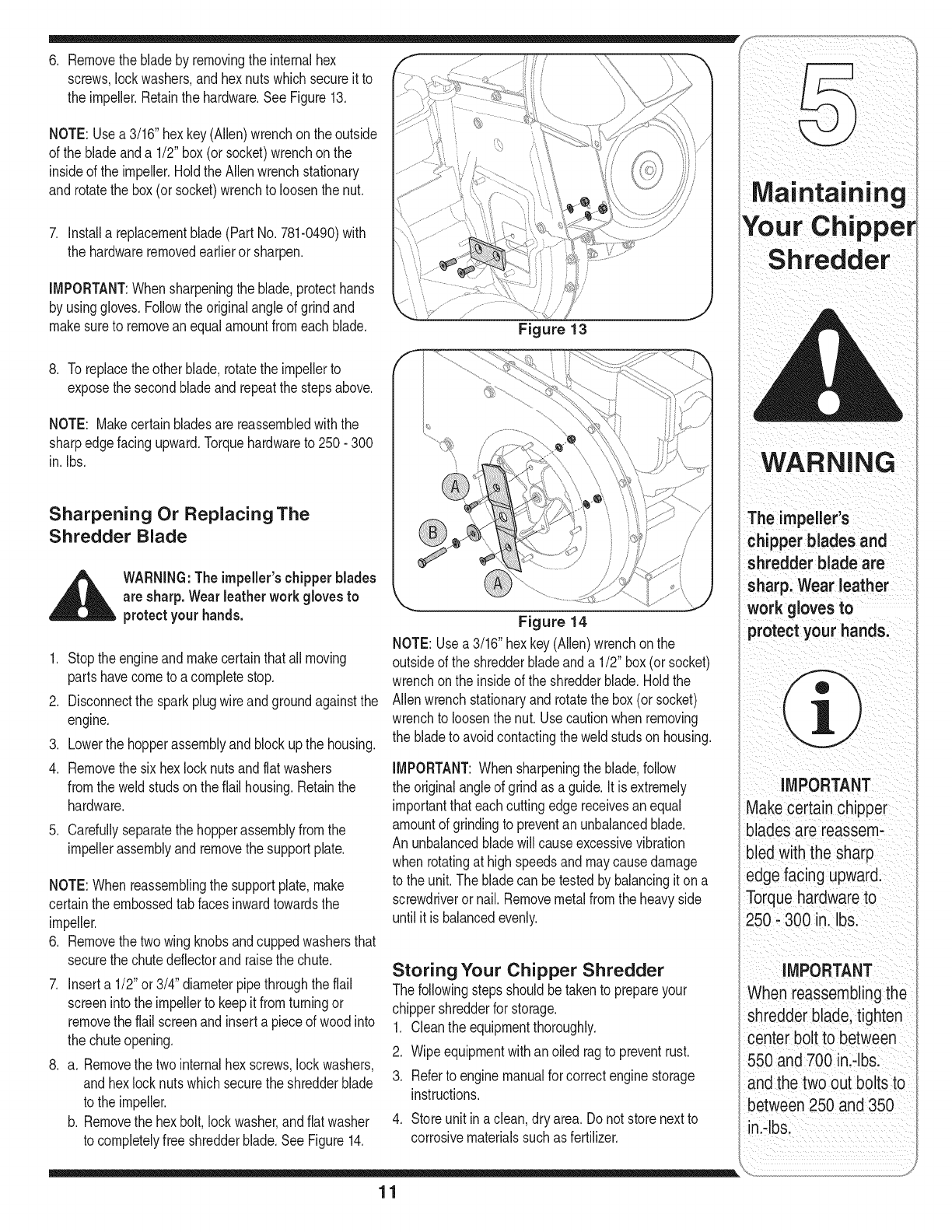
6. Removethe bladeby removingthe internalhex
screws,lockwashers,andhexnutswhichsecureitto
the impeller.Retainthe hardware.SeeFigure13.
NOTE: Usea 3/16"hex key(Allen)wrenchonthe outside
of the bladeanda 1/2" box(or socket)wrenchonthe
insideof the impeller.HoldtheAllenwrenchstationary
and rotatethe box(or socket)wrenchto loosenthe nut.
7. Installa replacementblade(PartNo.781-0490)with
the hardwareremovedearlieror sharpen.
IMPORTANT:Whensharpeningthe blade,protecthands
by usinggloves.Followthe originalangleof grindand
makesureto removean equalamountfromeachblade.
8. To replacethe otherblade,rotatethe impellerto
exposethe secondbladeandrepeatthe stepsabove.
NOTE: Makecertainbladesarereassembledwiththe
sharpedgefacingupward.Torquehardwareto 250- 300
in. Ibs.
Figure 13
Sharpening Or Replacing The
Shredder Blade
_ARNING:Theimpeller'schipperblades
are sharp. Wearleather work gloves to
__ protectyour hands.
1. Stop theengineand makecertainthatall moving
partshavecometo acompletestop.
2. Disconnectthe sparkplugwireandgroundagainstthe
engine.
3. Lowerthe hopperassemblyandblockupthe housing.
4. Removethe sixhex locknutsandflatwashers
fromthe weldstudson theflail housing.Retainthe
hardware.
5. Carefullyseparatethe hopperassemblyfromthe
impellerassemblyandremovethe supportplate.
NOTE:When reassemblingthe supportplate,make
certaintheembossedtab facesinwardtowardsthe
impeller.
6. Removethe twowing knobsandcuppedwashersthat
securethe chutedeflectorandraisethe chute.
7. Inserta 1/2"or 3/4" diameterpipethroughthe flail
screenintothe impellerto keepit fromturningor
removethe flail screenand inserta pieceof wood into
the chuteopening.
8. a. Removethe twointernalhex screws,lockwashers,
and hexlocknutswhichsecurethe shredderblade
to the impeller.
b. Removethe hexbolt,lockwasher,andflatwasher
to completelyfree shredderblade.See Figure14.
Figure 14
NOTE:Usea3/16"hexkey(Allen)wrenchon the
outsideof the shredderbladeanda 1/2" box(orsocket)
wrenchonthe insideof the shredderblade.Holdthe
Allenwrenchstationaryandrotatethe box (orsocket)
wrenchto loosenthenut. Usecautionwhen removing
the bladeto avoidcontactingthe weldstudson housing.
IMPORTANT:Whensharpeningthe blade,follow
the originalangleof grindas a guide.It is extremely
importantthateachcuttingedgereceivesanequal
amountof grindingto preventan unbalancedblade.
Anunbalancedbladewill causeexcessivevibration
whenrotatingat highspeedsandmaycausedamage
to the unit.Thebladecan betestedby balancingit on a
screwdriveror nail. Removemetalfromthe heavyside
until it is balancedevenly.
Storing Your Chipper Shredder
Thefollowingstepsshouldbetakento prepareyour
chippershredderfor storage.
1. Cleantheequipmentthoroughly.
2. Wipeequipmentwithanoiled ragto preventrust.
3. Referto enginemanualforcorrectenginestorage
instructions.
4. Storeunit ina clean,dry area. Donot storenextto
corrosivematerialssuchas fertilizer.
WARi ,,ING
The impeller S
chipper blades and
shredder blade are
work gloves to
protect your hands:
IMPORTANT
Makecertain chipper
bladesare reassem-
bledwith the sharp
edge facing upward.
Torquehardwareto
250- 300 in. Ibs.
iMPORTANT
When reassemblingthe
shredder blade, tighten
center bolt to between
550 and 700 in.-Ibs.
andthe two out bolts to
between250 and 350
in.-Ibs.
11
For repairs beyond
the minor adjustments
listed here, contact
an authorized service
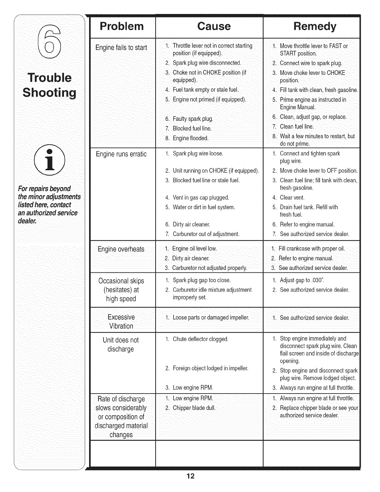
Problem Cause Remedy
En_in f_il rf I 1 Throtte ever not n correctstart ng 1 Movethrotte everto FASTor
=e_ stosta,
position(ifequipped). STARTposition,
2. Sparkplugwire disconnected, 2. Connectwire to sparkplug.
3. Chokenot inCHOKEposition(if 3. Movechokeleverto CHOKE
equipped), position.
4. Fueltankemptyorstalefuel. 4. Filltankwithclean,freshgasoline.
5. Enginenot primed(if equipped). 5. Primeengineas nstructedin
EngineManual.
6. Fauty sparkpug. 6. C can adjustgap or repace.
7, Blockedfuel line. I 7. Cleanfuel line.
8. Engineflooded. 8. Waitafew m nutesto restart,but
do not prime.
Engineruns erratic 1, Sparkplugwireloose, 1, Connectandtightenspark
plugwire,
2, UnitrunningonCHOKE(if equipped), 2, Movechokeleverto OFFposition,
3. Blockedfuellineor stalefuel. 3. Cleanfuel line;fill tankwithclean,
freshgasoline.
4. Ventingas cap plugged. 4. Clearvent.
5. Waterordirt infuel system. 5. Drainfuel tank. Refillwith
freshfuel.
6. Dirty aircleaner. 6. Referto enginemanual.
7. Carburetorout of adjustment. 7. Seeauthorizedservicedealer.
Engine overheats 1. Engineoil levellow. 1. Fillcrankcasewithproperoil.
I2 Drtyarceaner I 2 Refertoengnemanua
• 3. Carburetornotadjustedproperly. " 3. Seeauthorizedservicedealer.
Occasionalskips 1. Sparkpluggaptooclose. 1. Adjustgap to .030".
(hesitates)at 2. Carburetoridlemixtureadjustment 2. Seeauthorizedservicedealer.
high speed improperlyset.
Excessive I 1. Loosepartsordamagedimpeler I 1 Seeauthorzed servce deeer
Nm
Vibration I I
Unit does not 1. Chutedeflectorclogged. 1. Stop engineimmediatelyand
discharge disconnectsparkplugwire.Clean
flail screenandinsideof discharge
opening.
2. Foreignobjectlodgedin impeller. 2. Stop engineanddisconnectspark
plugwire.Removelodgedobject.
3. LowengineRPM. 3. Alwaysrunengineat full throttle.
Rate of discharge 1 LowengineRPM. 1. Alwaysrunengineat fullthrottle.
slows considerably I 2. Chipperbladedul. I 2. Replacechipperbladeor seeyour
or composition of authorzed servcedeeer.
changes ,
12
_ii ii i_ ___ i iiiiii ii ii ii_i _ i
usethispagetomake
notes and write down
important information,
13
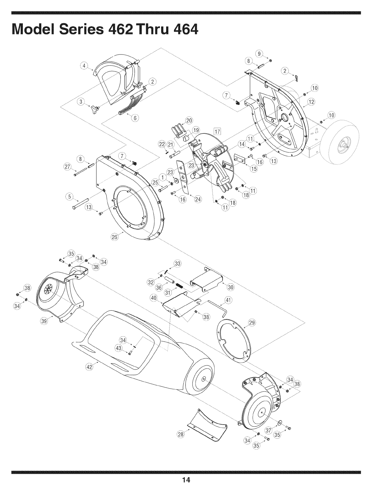
odel Series 462 Thru 464
- ' .._ .,q8;
14
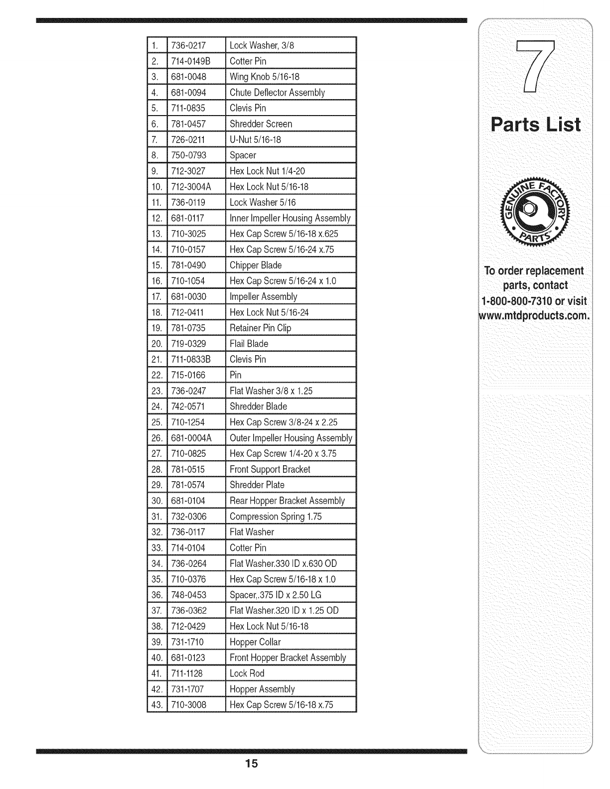
1. 736-0217 LockWasher,3/8
2. 714-0149B CotterPin
3. 681-0048 Wing Knob5/16-18
4. 681-0094 ChuteDeflectorAssembly
5. 711-0835 ClevisPin
6. 781-0457 ShredderScreen
7. 726-0211 U-Nut5/16-18
8. _ 750-0793 _ Spacer
9. 712-3027 HexLockNut1/4-20
10. 712-3004A HexLockNut5/16-18
11. 736-0119 LockWasher5/16
12. 681-0117 Inner ImpellerHousingAssembly
13. 710-3025 HexCapScrew5/16-18x.625
14. 710-0157 HexCapScrew5/16-24x.75
15. 781-0490 ChipperBlade
16. 710-1054 HexCapScrew5/16-24x 1.0
17. 681-0030 impellerAssembly
18. 712-0411 HexLockNut5/16-24
19. 781-0735 RetainerPinClip
20. 719-0329 Flail Blade
21. 711-0833B ClevisPin
22. 715-0166 Pin
23. 736-0247 FlatWasher3/8 x 1.25
24. 742-0571 ShredderBlade
25. 710-1254 HexCapScrew3/8-24 x 2.25
26. 681-0004A OuterImpellerHousingAssembly
27. 710-0825 HexCapScrew1/4-20x 3.75
28. 781-0515 FrontSupportBracket
29. 781-0574 ShredderPlate
30. 681-0104 RearHopperBracketAssembly
31. 732-0306 CompressionSpring1.75
32. 736-0117 FlatWasher
33. 714-0104 CotterPin
34. 736-0264 FiatWasher.330IDx.630OD
35. 710-0376 HexCapScrew5/16-18x 1.0
36. 748-0453 Spacer,.375IDx 2.50 LG
37. 736-0362 FiatWasher.320IDx 1.25OD
38. 712-0429 HexLockNut5/16-18
39. 731-1710 HopperCollar
40. 681-0123 FrontHopperBracketAssembly
41. 711-1128 LockRod
42. 731-1707 HopperAssembly
43. 710-3008 HexCapScrew5/16-18x.75
To order replacement
parts, contact
1=800-800-7310or visit
www.mtdproducts.com.
15
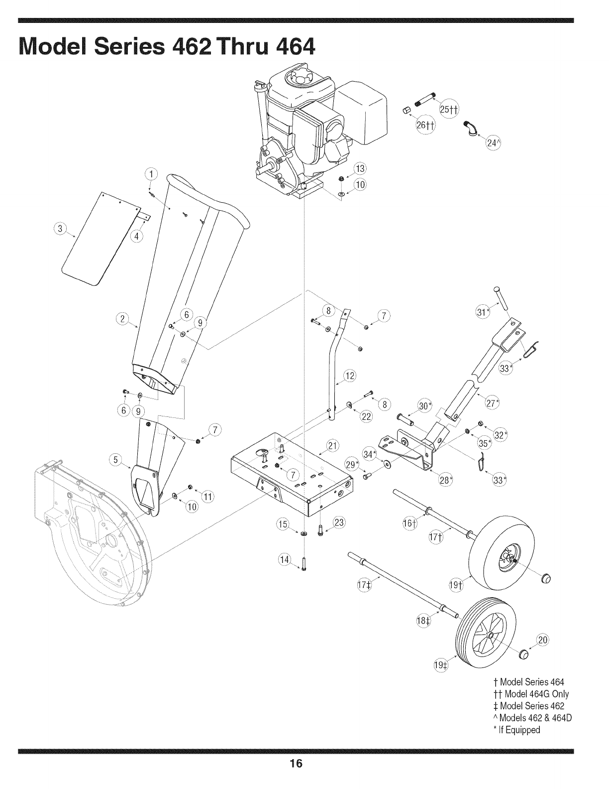
odel Series 462 Thru 464
1 ModelSeries464
11 Model464GOnly
ModelSeries462
^ Models462& 464D
* If Equipped
16
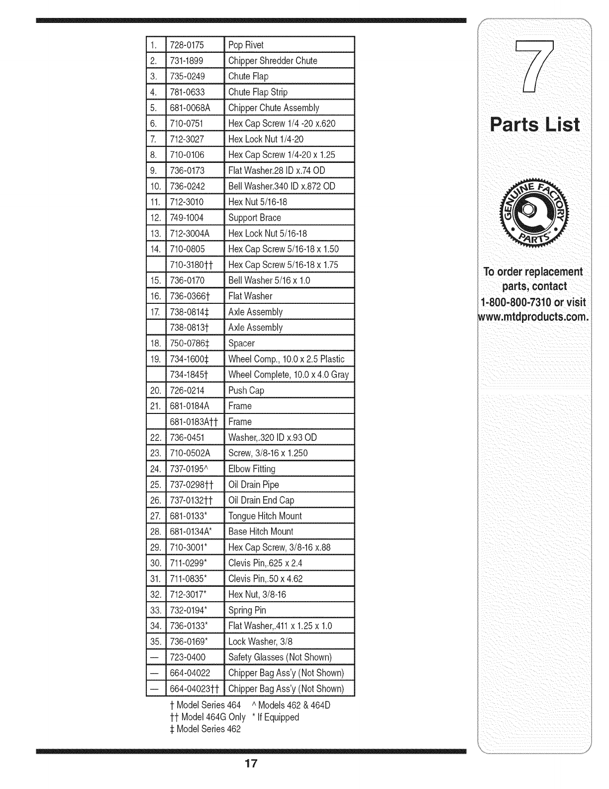
1. 728-0175 PopRivet
2. 731-1899 ChipperShredderChute
3. 735-0249 ChuteFlap
4. 781-0633 ChuteFlapStrip
5. 681-0068A ChipperChuteAssembly
6. 710-0751 HexCapScrew1/4-20x.620
7. 712-3027 HexLockNut1/4-20
8. _ 710-0106 HexCapScrew1/4-20x 1.25
9. 736-0173 FiatWasher.28IDx.74OD
10. 736-0242 BellWasher.340IDx.872OD
11. 712-3010 HexNut5/16-18
12. 749-1004 SupportBrace
13. 712-3004A HexLockNut5/16-18
14. 710-0805 HexCapScrew5/16-18x 1.50
710-3180tt HexCapScrew5/16-18x 1.75
15. 736-0170 BellWasher5/16x 1.0
16. 736-0366t FlatWasher
17. 738-0814_1 AxleAssembly
738-0813t AxleAssembly
18. 750-0786_: Spacer
19. 734-1600:_ WheelComp.,10.0x 2.5 Plastic
734-1845t WheelComplete,10.0x 4.0 Gray
20. 726-0214 PushCap
21. 681-0184A Frame
681-0183Att Frame
22. 736-0451 Washer,.320IDx.93OD
23. 710-0502A Screw,3/8-16x 1.250
24. 737-0195A ElbowFitting
25. 737-0298tt Oil DrainPipe
26. 737-0132tt Oil DrainEndCap
27. 681-0133" TongueHitchMount
28. 681-0134A* Base HitchMount
29. 710-3001" HexCapScrew,3/8-16x.88
30. 711-0299" ClevisPin,.625x 2.4
31. 711-0835" ClevisPin,.50x 4.62
32. 712-3017" HexNut,3/8-16
33. 732-0194" SpringPin
34. 736-0133" FiatWasher,.411x 1.25x 1.0
35. 736-0169" LockWasher,3/8
-- 723-0400 SafetyGlasses(NotShown)
k
-- 664-04022 ChipperBagAss'y(Not Shown)
-- 664-04023tt ChipperBagAss'y(Not Shown)
t ModelSeries464 AModels462& 464D
tt Model464GOnly * IfEquipped
_1ModelSeries462
17
To order replacement
parts, contact
1-800-800-7310 or visit
www.mtdproducts.com.

Use this page to make
notes and write down
important information:
18

notes and write down
important information:
19
MANUFACTURER'S LiMiTED WARRANTY FOR
The limitedwarrantysetforthbelowisgivenby MTDLLCwithrespectto
newmerchandisepurchasedandusedin the UnitedStates,itsposses-
sionsandterritories.
"MTD"warrantsthisproductagainstdefectsin materialandworkmanship
for a periodof two(2) yearscommencingonthe dateof originalpurchase
andwill,at its option,repairor replace,free of charge,anypart foundto
bedefectiveinmaterialsor workmanship.Thislimitedwarrantyshallonly
applyif this producthas beenoperatedandmaintainedinaccordance
withthe Operator'sManualfurnishedwiththe product,andhas not been
subjectto misuse,abuse,commercialuse,neglect,accident,improper
maintenance,alteration,vandalism,theft,fire,water,ordamagebecause
of otherperilor naturaldisaster.Damageresultingfromthe installationor
useof any part,accessoryorattachmentnotapprovedby MTDfor use
withthe product(s)coveredbythis manualwill voidyourwarrantyas to
any resultingdamage.
Normalwearpartsarewarrantedto befree fromdefectsinmaterialand
workmanshipfor a periodof thirty (30)daysfromthe dateof purchase.
Normalwearpartsinclude,butare notlimitedto itemssuchas: batteries,
belts,blades,bladeadapters,grassbags,riderdeckwheels,seats,snow
throwerskidshoes,shaveplates,augerspiralrubberandtires.
HOW TO OBTAIN SERVICE: Warranty service is available,WITH
PROOFOF PURCHASE, through your local authorized service
dealer. To locate the dealer in your area, check your Yellow Pages, or
contact MTD LLC at RO. Box 361131,Cleveland, Ohio 44136-0019,or
call 1-800-800-7310or 1-330-220-4683or log on to our Web site at
www.mtdproducts.com.
Thislimitedwarrantydoesnot providecoverageinthe followingcases:
a. Theengineor componentpartsthereof.Theseitemsmaycarrya
separatemanufacturer'swarranty.Referto applicablemanufacturer's
warrantyfor termsandconditions.
b. Logsplitterpumps,valves,andcylindershavea separateoneyear
warranty.
c. Routinemaintenanceitemssuchas lubricants,filters,blade
sharpening,tune-ups,brakeadjustments,clutchadjustments,deck
adjustments,andnormaldeteriorationof the exteriorfinishdueto use
orexposure.
d. Servicecompletedby someoneotherthananauthorizedservice
dealer.
e. MTDdoes notextendany warrantyfor productssoldor exported
outsideof the UnitedStates,itspossessionsandterritories,except
thosesoldthroughMTD'sauthorizedchannelsof exportdistribution.
f. Replacementpartsthatarenot genuineMTDparts.
g. Transportationchargesand servicecalls.
No impliedwarranty,includingany impliedwarranty of merchant-
ability of fitness for a particularpurpose,applies after the applicable
periodof express written warranty above as to the partsas identi-
fied. No other express warranty, whether written or oral, except as
mentionedabove,givenby any personor entity,includingadealer
or retailer,with respect to any product,shallbind MTD.Duringthe
periodof the warranty, the exclusive remedyis repairor replacement
of the productas set forth above.
The provisionsas set forth inthis warranty providethe sole and
exclusive remedyarising from the sale. MTDshall not be liable
for incidentalor consequential loss or damage including,without
limitation, expenses incurredfor substitute or replacementlawn care
services or for rentalexpenses to temporarily replacea warranted
product.
Somestatesdo not allowtheexclusionor limitationof incidentalor
consequentialdamages,or limitationson howlonganimpliedwarranty
lasts,so the aboveexclusionsor limitationsmaynotapplyto you.
In noeventshall recoveryof any kind begreaterthan theamountof the
purchasepriceof the productsold.Alterationof safetyfeatures of the
productshall void this warranty. Youassumethe riskandliabilityfor
loss, damage,or injuryto youandyour propertyand/orto othersandtheir
propertyarisingout of the misuseor inabilityto use theproduct.
Thislimitedwarrantyshall notextendto anyoneotherthanthe original
purchaseror to the personfor whomitwaspurchasedas a gift.
HOWSTATELAWRELATESTO THISWARRANTY: Thislimitedwar-
rantygivesyouspecificlegalrights,andyou mayalso haveother rights
whichvaryfromstateto state.
IMPORTANT: OwnermustpresentOriginalProofof Purchaseto obtain
warrantycoverage.
MTD LLC, P.O. BOX 361131 CLEVELAND, OHIO 44136-0019; Phone: 1-800-800-7310, 1-330-220-4683
