MTD 24BF570L099 User Manual LOG SPLITTER Manuals And Guides L1005268
User Manual: MTD 24BF570L099 24BF570L099 MTD LOG SPLITTER - Manuals and Guides View the owners manual for your MTD LOG SPLITTER #24BF570L099. Home:Lawn & Garden Parts:MTD Parts:MTD LOG SPLITTER Manual
Open the PDF directly: View PDF ![]() .
.
Page Count: 60

Operator's Manual
CRRFrSM ®
675 Series
LOG SPLITTER
Model No. 247.77640
CAUTION: Before using
this product, read this
manual and follow all
safety rules and operating
instructions.
o SAFETY
ASSEMBLY
OPERATION
MAINTENANCE
PARTS LIST
Espa_ol
Sears, Roebuck and Co., Hoffman Estates, IL 60179, U.S.A.
Visit our web site: www.sears.com/craftsman FORMNO.769-05144
6/7/2009
WarrantyStatement..................................Pac
SafeOperationPractices..........................Pac
SafetyLabels............................................Pac
Assembly..................................................Pac
Operation..................................................Pac
Service&Adjustments.............................Pac
Maintenance.............................................Pac
e2
es3-5
e6
es7-9
es10-13
es14
es15-17
OffSeasonStorage..................................Page18
Troubleshooting........................................Page20-21
PartsList...................................................Page22-35
RepairProtectionAgreement...................Page36
Espa_ol.....................................................Page37
ServiceNumbers......................................BackCover
CRAFTSMANFULLWARRANTY
Whenoperatedandmaintainedaccordingtoallsuppliedinstructions,ifthisCraftsmanlogsplitterfailsdueto
adefectinmaterialorworkmanshipwithinoneyearfromthedateof purchase,call1-800-4-MY-HOME®to
arrangeforfreerepair(orreplacementif repairprovesimpossible).
Thiswarrantyappliesforonly90daysfromthedateof purchaseifthislogsplitteriseverusedforcommercial
orrentalpurposes.
This warranty covers ONLY defects in material and workmanship. Sears will NOT pay for:
• Expendable items that become worn during normal use, including but not limited to spark plug, air cleaner,
belts, and oil filter.
• Standard maintenance servicing, oil changes, or tune=ups.
• Tire replacement or repair caused by punctures from outside objects, such as nails, thorns, stumps, or glass.
• Tire or wheel replacement or repair resulting from normal wear, accident, or improper operation or
maintenance.
• Repairs necessary because of operator abuse, including but not limited to damage caused by over-speeding
the engine, or from impacting objects that bend the frame, auger shaft, etc.
• Repairs necessary because of operator negligence, including but not limited to, electrical and mechanical
damage caused by improper storage, failure to use the proper grade and amount of engine oil, or failure to
maintain the equipment according to the instructions contained in the operator's manual.
• Engine (fuel system) cleaning or repairs caused by fuel determined to be contaminated or oxidized (stale). In
general, fuel should be used within 30 days of its purchase date.
• Normal deterioration and wear of the exterior finishes, or product label replacement.
This warranty applies only while this product is within the United States.
This warranty gives you specific legal rights, and you may also have other rights which vary from state to state.
Sears, Roebuck and Co., Hoffman Estates, IL 60179
Engine Series: 126T02-0523
Engine Oil: SAE 30
Engine Oil Capacity: 20 Ounces
Fuel Capacity: 1.5 Quarts
Spark Plug (.030" Gap): Champion® RJ19LM
Hydraulic Fluid/Capacity: Dexron® III/3.0 gal.
Model Number .............................................................
Serial Number ..............................................................
Date of Purchase ..........................................................
Record the model number, serial number
and date of purchase above
2
This symbol points out important safety
instructions which, if not followed, could
endanger the personal safety and/or property of
yourself and others. Read and follow all
instructions in this manual before attempting to
operate this machine. Failure to comply with
these instructions may result in personal injury.
When you see this symbol, HEED ITS WARNING!
CALIFORNIA PROPOSITION 65
Engine Exhaust, some of its constituents, and certain vehicle
components contain or emit chemicals known to State
of California to cause cancer and birth defects or other
reproductive harm.
This machine was built to be operated according to the
safe operation practices in this manual. As with any type of
power equipment, carelessness or error on the part of the
operator can result in serious injury. This machine is capable
of amputating fingers, hands, toes and feet and throwing
debris. Failure to observe the following safety instructions
could result in serious injury or death.
Your Responsibility--Restrict the use of this power
machine to persons who read, understand and follow
the warnings and instructions in this manual and on the
machine.
SAVETHESEINSTRUCTIONS!
Training lo.
1. Read, understand, and follow all instructions on the machine
and in the manual before attempting to assemble and
operate. Keep this manual in a safe place for future and regular
reference and for ordering replacement parts.
2. Read the Operator's Manual and follow all warnings and safety
instructions. Failure to do so can result in serious injury to the
operator and/or bystanders. For questions call, 1-800-4-MY-
HOME.
3. Be familiar with all controls and their proper operation. Know
how to stop the machine and disengage them quickly.
4. Never allow children under 16 years of age to operate this
machine. Children 16 and over should read and understand the
instructions and safe operation practices in this manual and on
the machine and be trained and supervised by an adult.
5. Never allow adults to operate this machine without proper
instruction.
6. Many accidents occur when more than one person operates
the machine. Ifa helper is assisting in stacking logs, never
activate the control until the helper is a minimum of 10 feet
from the machine.
Z Keep bystanders, pets, and children at least 20 feet from the
machine while it is in operation.
8. Never allow anyone to ride on this machine.
9. Never transport ca rgo on this machine.
Hydraulic log splitters develop high fluid pressures during
operation. Fluid escaping through a pin hole opening can
penetrate your skin and cause blood poisoning, gangrene, or
death. Give attention to the following instructions at all times:
a. Do not check for leaks with your ha nd.
b. Do not operate machine with frayed, kinked, cracked, or
damaged hoses, fittings, or tubing.
c. Stop the engine and relieve hydraulic system pressure
before changing or adjusting fittings, hoses, tubing, or
other system components.
d. Do not adjust the pressure settings of the pump or
valve.
10. Leaks can be detected by passing cardboard or wood,
while wearing protective gloves and safety glasses, over the
suspected area. Look for discoloration of cardboard or wood.
11. If injured by escaping fluid, see a doctor immediately. Serious
infection or reaction can develop if proper medical treatment
is not administered immediately.
12. Keep the operator zone and adjacent area clear for safe, secure
footing.
13. If your machine is equipped with an internal combustion
engine and is intended for use near any unimproved forest,
brush, or grass covered land, the engine exhaust should be
equipped with a spark attester. Make sure you comply with
applicable local, state, and federal codes. Take appropriate
firefighting equipment with you.
14. This machine should be used for splitting wood only; do not
use it for any other purpose.
15. Follow the instructions in the manual(s) provided with any
attachment(s) for this machine.
3
Preparation Operation
1. Always wear safety shoes or heavy boots.
2. Always wear safety glasses or safety goggles when operating
this machine.
3. Never wear jewelry or loose clothing that might become
entangled in moving or rotating parts of the machine.
4. Make sure machine is on a level surface before operating.
5. Always block wheels to prevent unintended movement,
and lock beam assembly in either the horizontal or vertical
position.
6. Always operate this machine from the operator zone(s)
specified in the manual.
7. Logs should be cut with square ends prior to splitting.
8. Use log splitter in daylight or under good artificial light.
SafeHandlingof Gasoline
To avoid personal injury or property damage use extreme care in
handling gasoline. Gasoline is extremely flammable and the vapors
are explosive. Serious personal injury can occur when gasoline is
spilled on yourself or your clothes which can ignite. Wash your skin
and change clothes immediately.
a. Use only an approved gasoline container.
b. Extinguish all cigarettes, cigars, pipes, and other sources
of ignition.
c. Never fuel machine indoors.
d. Never remove gas cap or add fuel while the engine is
hot or running.
e. Allow engine to cool at least two minutes before
refueling.
fl Never overfill the fuel tank. Fill tank to no more than 1/2
inch below bottom of filler neck to provide space for
fuel expansion.
g. Replace gasoline cap and tighten securely.
h. If gasoline is spilled, wipe it off the engine and
equipment and move machine to another area. Wait five
(5) minutes before starting the engine.
i. Never store the machine or fuel container inside where
there is an open flame, spark or pilot light as on a water
heater, space heater, furnace, clothes dryer or other gas
appliances.
j. Allow machine to cool at least five (5) minutes before
storing.
1. Before starting this machine, review the "Safety Instructions".
Failure to follow these rules may result in serious injury to the
operator or bystanders.
2. Never leave this machine unattended with the engine running.
3. Do not operate machine while under the influence of alcohol,
drugs, or medication.
4. Never allow anyone to operate this machine without proper
instruction.
5_
6_
Always operate this machine with all safety equipment in place
and working. Make sure all controls are properly adjusted for
safe operation.
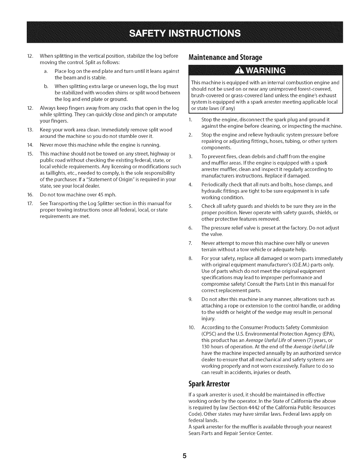
Operator Zone
a. Horizontal Operating Position: Stand behind the
reservoir tank to operate the control handle and to
stabilize the log as shown in Fig. 1.
b. Vertical Operating Position: Stand in front of the beam
and log as shown in Fig. 1.
Horizontal
Vertical
Figure 1
7. Do not change the engine governor settings or overspeed the
engine. The governor controls the maximum safe operating
speed of the engine.
8. When loading a log, always place your hands on the sides
of the log, not on the ends, and never use your foot to help
stabilize a log. Failure to do so, may result in crushed or
amputated fingers, toes, hand, or foot.
9. Use only your hand to operate the controls.
10. Never attempt to split more than one log at a time unless
the ram has fully extended and a second log is needed to
complete the separation of the first log.
11. For logs which are not cut square, the least square end and the
longest portion of the log should be placed toward the beam
and wedge, and the square end placed toward the end plate to
ensure the log remains level and in place on the end plate.
4
12. When splitting in the vertical position, stabilize the log before
moving the control. Split as follows:
a. Place log on the end plate and turn until it leans against
the beam and is stable.
b. When splitting extra large or uneven logs, the log must
be stabilized with wooden shims or split wood between
the log and end plate or ground.
12. Always keep fingers away from any cracks that open in the log
while splitting. They can quickly close and pinch or amputate
your fingers.
13. Keep your work area clean. Immediately remove split wood
around the machine so you do not stumble over it.
14. Never move this machine while the engine is running.
15. This machine should not be towed on any street, highway or
public road without checking the existing federal, state, or
local vehicle requirements. Any licensing or modifications such
as taillights, etc., needed to comply, is the sole responsibility
of the purchaser. If a "Statement of Origin" is required in your
state, see your local dealer.
16. Do not tow machine over 45 mph.
17. See Transporting the Log Splitter section in this manual for
proper towing instructions once all federal, local, or state
requirements are met.
Maintenanceand Storage
This machine is equipped with an internal combustion engine and
should not be used on or near any unimproved forest-covered,
brush-covered or grass-covered land unless the engine's exhaust
system is equipped with a spark arrester meeting applicable local
or state laws (if any)
1. Stop the engine, disconnect the spark plug and ground it
against the engine before cleaning, or inspecting the machine.
2. Stop the engine and relieve hydraulic system pressure before
repairing or adjusting fittings, hoses, tubing, or other system
components.
3. To prevent fires, clean debris and chaff from the engine
and muffler areas. If the engine is equipped with a spark
attester muffler, clean and inspect it regularly according to
manufacturers instructions. Replace if damaged.
4. Periodically check that all nuts and bolts, hose clamps, and
hydraulic fittings are tight to be sure equipment is in safe
working condition.
5. Check all safety guards and shields to be sure they are in the
proper position. Never operate with safety guards, shields, or
other protective features removed.
The pressure relief valve is preset at the factory. Do not adjust
the valve.
6_
7.
8.
10.
Never attempt to move this machine over hilly or uneven
terrain without a tow vehicle or adequate help.
For your safety, replace all damaged or worn parts immediately
with original equipment manufacturer's (O.E.M.) parts only.
Use of parts which do not meet the original equipment
specifications may lead to improper performance and
compromise safety! Consult the Parts List in this manual for
correct replacement parts.
Do not alter this machine in any manner, alterations such as
attaching a rope or extension to the control handle, or adding
to the width or height of the wedge may result in personal
injury.
According to the Consumer Products Safety Commission
(CPSC) and the U.S. Environmental Protection Agency (EPA),
this product has an Average Useful Life of seven (7) years, or
130 hou rs of operation. At the end of the Average Useful Life
have the machine inspected annually by an authorized service
dealer to ensure that all mechanical and safety systems are
working properly and not worn excessively. Failure to do so
can result in accidents, injuries or death.
SparkArrestor
Ira spark arrester is used, it should be maintained in effective
working order by the operator. In the State of California the above
is required by law (Section 4442 of the California Public Resources
Code). Other states may have similar laws. Federal laws apply on
federal lands.
A spark attester for the muffler is available through your nearest
Sears Parts and Repair Service Center.
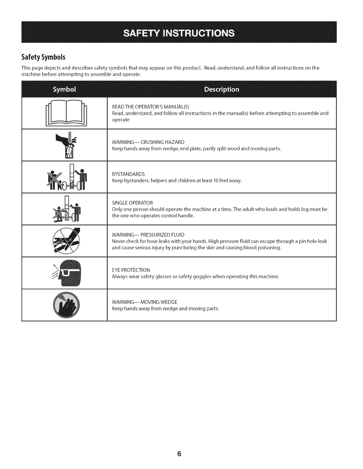
SafetySymbols
This page depicts and describes safety symbols that may appear on this product. Read, understand, and follow all instructions on the
machine before attempting to assemble and operate.
° I °_ READ THE OPERATOR'S MANUAL(S)
I
I
I
II
i/
Read, understand, and follow all instructions in the manual(s) before attempting to assemble and
operate
WARNING-- CRUSHING HAZARD
Keep hands away from wedge, end plate, partly split wood and moving parts.
BYSTANDARDS
Keep bystanders, helpers and children at least 10 feet away.
SINGLE OPERATOR
Only one person should operate the machine at a time. The adult who loads and holds log must be
the one who operates control handle.
WARNING-- PRESSURIZED FLUID
Never check for hose leaks with your hands. High pressure fluid can escape through a pin hole leak
and cause serious injury by puncturing the skin and causing blood poisoning.
EYEPROTECTION
Always wear safety glasses or safety goggles when operating this machine.
WARNING-- MOVING WEDGE
Keep hands away from wedge and moving parts.
6
NOTE:Yourlogsplitteris shippedwith motoroilin the engine.
However,you MUSTcheckthe oil levelbeforeoperating.Becareful
notto overfill.
NOTE:All referencesin thismanualto the leftor right sideof the log
splitterarefromtheoperatingpositiononly.SeeOperatorZonein the
Operationsectionof the SafetyInstructions.
REMOVING THE LOG SPLITTER FROM THE
CARTON
1. Pry thetop,sidesandendsoff of the crate.
2. Setthe panelsasideto avoidtire puncturesor personalinjury.
3. Removeanddiscardthe plasticbagthatcoversthe logsplitter.
4. Removeany loosepartsincludedwithwiththe log splitter(i.e.,
toungueassembly,operator'smanual,etc.)
5. Cutandremovethe strapswhichsecurethe partsto the bottom
of the crate.Unboltany remainingpartswhichmaybeboltedto
the bottomof the crate.
Useextremecautionunpackingthismachine.Somecomponentsare
veryheavyandwill requireadditionalpeopleor mechanicalhandling
equipment.
LOOSE PARTS IN CARTON
1. TongueAssembly
ASSEMBLING THE TONGUE
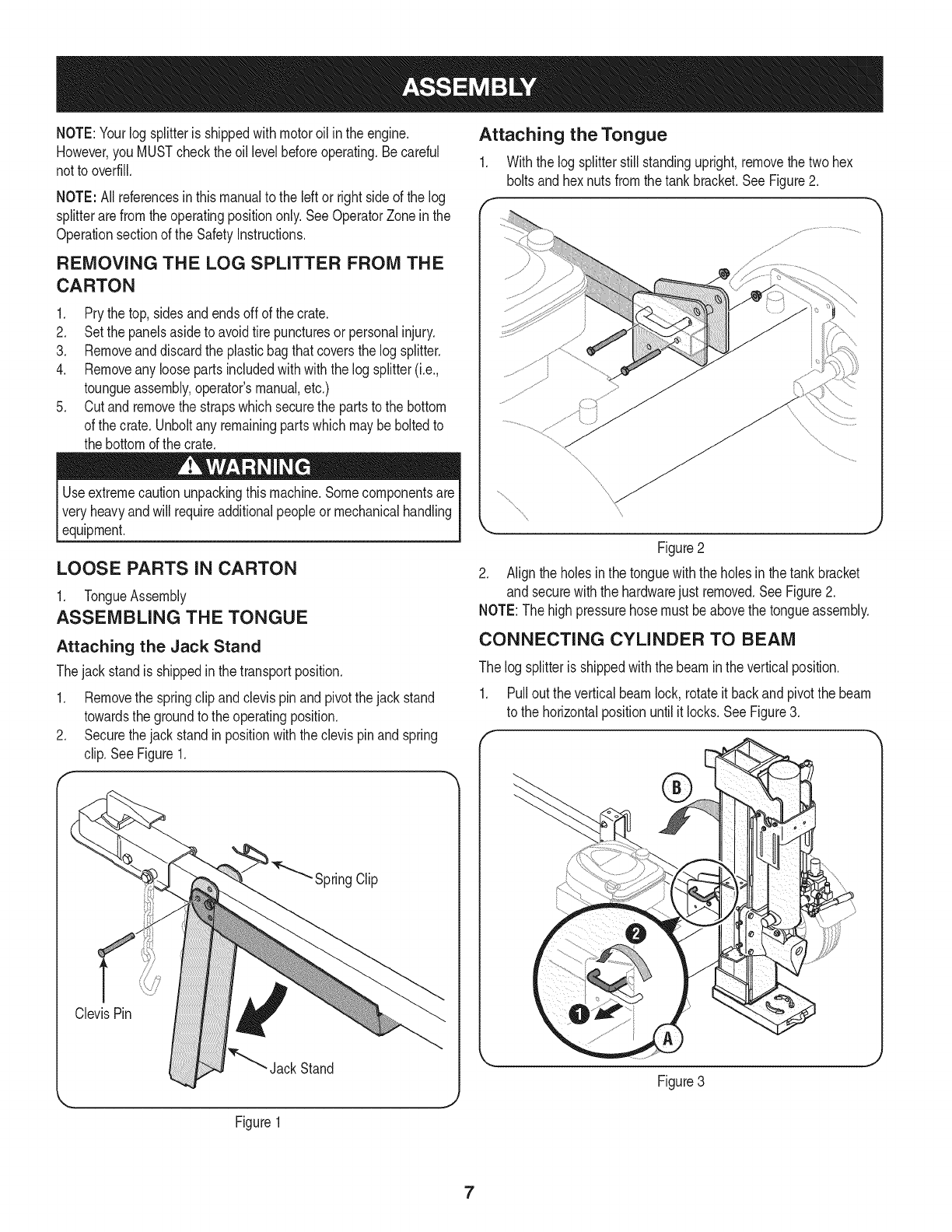
Attaching the Jack Stand
Thejackstandisshippedinthe transportposition.
1. Removethe springclip andclevispinand pivotthejackstand
towardsthe groundto theoperatingposition.
2. Securethe jackstandinpositionwiththe clevispinandspring
clip.SeeFigure1.
SpringClip
ClevisPin
Jack Stand
Figure1
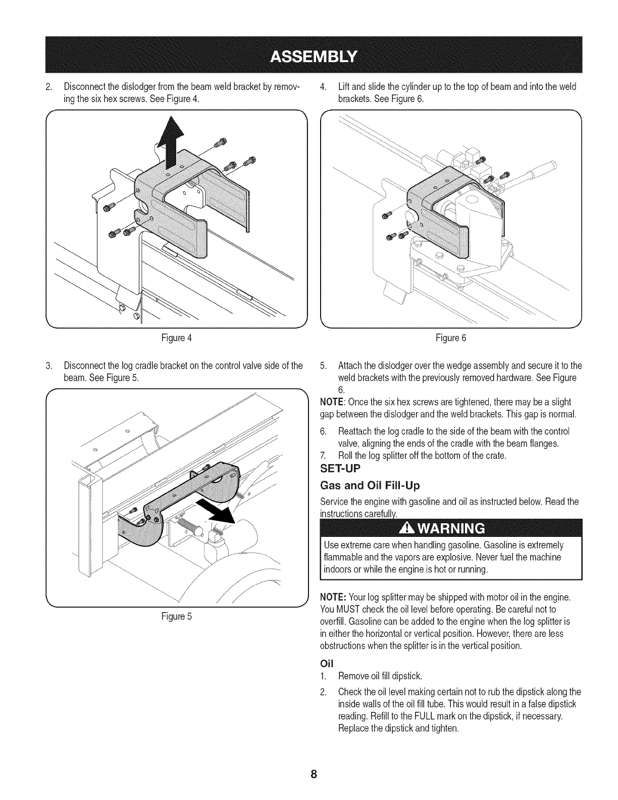
Attaching the Tongue
1. Withthe log splitterstill standingupright,removethe twohex
boltsandhex nutsfromthe tankbracket.SeeFigure2.
J
Figure2
2. Alignthe holesinthe tonguewiththe holesinthe tankbracket
and securewiththe hardwarejust removed.See Figure2.
NOTE:The highpressurehosemustbe abovethe tongueassembly.
CONNECTING CYLINDER TO BEAM
The logsplitteris shippedwiththe beamin the verticalposition.
1. Pullout the verticalbeamlock, rotateit backandpivotthe beam
to the horizontalpositionuntil it locks.SeeFigure3.
J
Figure3
7
2. Disconnectthe dislodgerfromthe beamweld bracketby remov-
ingthe sixhex screws.SeeFigure4.
4. Liftandslidethe cylinderupto the top of beamandintothe weld
brackets.SeeFigure6.
Figure4 Figure6
.Disconnectthe logcradlebracketon the controlvalveside of the
beam.SeeFigure5.
5. Attachthe dislodgeroverthe wedgeassemblyandsecureit to the
weld bracketswiththe previouslyremovedhardware.SeeFigure
6.
NOTE:Oncethe six hexscrewsaretightened,there maybea slight
gap betweenthe dislodgerandtheweld brackets.Thisgap is normal.
6. Reattachthe logcradleto the sideof the beamwiththe control
valve,aligningtheends of thecradlewiththe beamflanges.
7. Rollthe logsplitteroffthe bottomof thecrate.
SET-UP
Gas and Oil Fill=Up
Servicetheenginewithgasolineandoilas instructedbelow.Readthe
i
Useextremecarewhen handlinggasoline.Gasolineis extremely
flammableand thevaporsare explosive.Neverfuel the machine
indoorsorwhilethe engineis hotor running.
Figure5
NOTE:Yourlogsplittermaybeshippedwithmotoroil in the engine.
YouMUSTcheckthe oil levelbeforeoperating.Becarefulnotto
overfill.Gasolinecan be addedto the enginewhenthe logsplitteris
ineitherthe horizontalorverticalposition.However,thereare less
obstructionswhenthe splitteris in the verticalposition.
Oil
1.
2.
Removeoil fill dipstick.
Checkthe oillevel makingcertainnotto rubthedipstickalongthe
insidewallsof the oilfill tube.Thiswouldresultin afalsedipstick
reading.Refillto the FULLmarkonthe dipstick,if necessary.
Replacethe dipstickandtighten.
8
3. If necessary,withthe logsplitteronlevelground,usea funnelto
fill enginewithoil to the FULLmarkon the dipstick.Becarefulnot
to overfill.Overfillingwill causethe engineto smokeprofuselyand
will resultin poorengineperformance.
4. Checkthe oil levelthreetimespriorto startingtheengineto be
certainyou'vegottenan accuratedipstickreading.Runningthe
enginewithtoo littleoilcan resultinpermanentenginedamage.
Gasoline
1. Removethe fuel cap fromthe fuel tank.
2. Makesurethe containerfromwhichyouwill pourthegasolineis
cleanandfreefromrustor foreignparticles.Neveruse gasoline
thatmaybestalefromlongperiodsof storagein itscontainer.
Gasolinethathasbeensittingfor anyperiodlongerthanfour
weeksshouldbeconsideredstale.
3. Fillthe fuel tankwithabout 1.5quartsof clean,freshgasolinewith
a minimumof 85 octane.
NOTE: Neveroverfillthe fuel tank.Fill tankto no morethan 1/2 inch
belowbottomof filler neckto providespacefor fuel expansion.
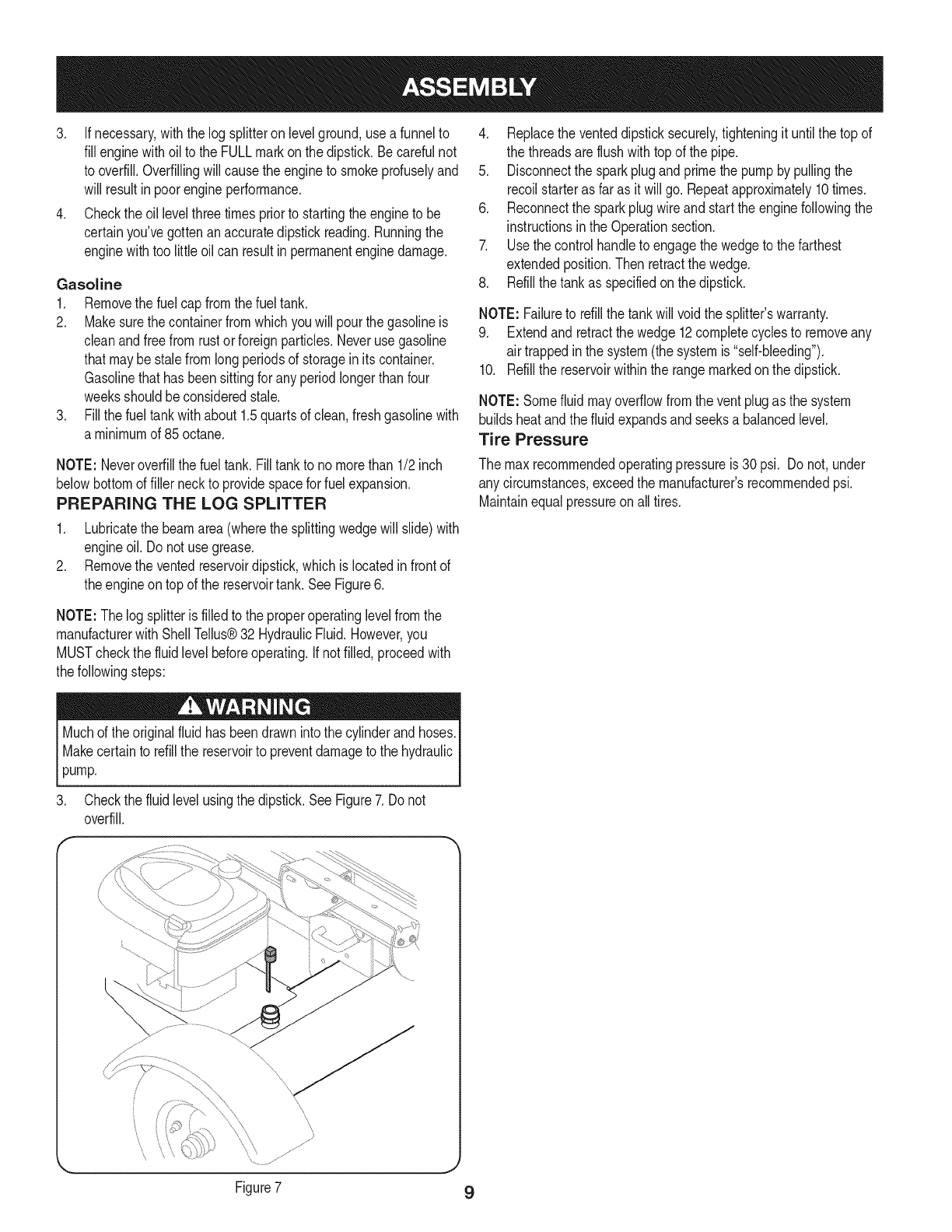
PREPARING THE LOG SPLITTER
1. Lubricatethe beamarea(wherethe splittingwedgewill slide)with
engineoil. Do notuse grease.
2. Removethe ventedreservoirdipstick,whichis locatedin frontof
theengineontop of the reservoirtank. SeeFigure6.
4. Replacethe venteddipsticksecurely,tighteningit untilthe top of
the threadsareflushwithtopof thepipe.
5. Disconnectthe sparkplugandprimethe pumpby pullingthe
recoilstarteras far as it willgo. Repeatapproximately10times.
6. Reconnectthe sparkplugwire andstart theenginefollowingthe
instructionsinthe Operationsection.
7. Usethe controlhandleto engagethe wedgeto thefarthest
extendedposition.Thenretractthewedge.
8. Refillthe tankas specifiedonthe dipstick.
NOTE: Failureto refillthe tankwill voidthe splitter'swarranty.
9. Extendandretractthe wedge12completecyclesto removeany
air trappedin the system(the systemis "self-bleeding").
10. Refillthe reservoirwithinthe rangemarkedon the dipstick.
NOTE: Somefluidmayoverflowfromthe ventplugas the system
buildsheatand thefluid expandsandseeksa balancedlevel.
Tire Pressure
The maxrecommendedoperatingpressureis 30 psi. Donot,under
any circumstances,exceedthe manufacturer'srecommendedpsi.
Maintainequalpressureonall tires.
NOTE:The logsplitteris filledto the properoperatinglevelfromthe
manufacturerwithShellTellus®32 HydraulicFluid.However,you
MUSTcheckthe fluid levelbeforeoperating.Ifnot filled,proceedwith
thefollowingsteps:
Muchof the originalfluid hasbeendrawnintothe cylinderand hoses.
Makecertainto refillthe reservoirto preventdamageto the hydraulic
pump.
3. Checkthe fluid levelusingthe dipstick.See Figure7.Do not
overfill.
\
\\
Figure7 9
Cylinder
Coupler
Hitch
lodger
ControlHandle
Horizontal
BeamLock
,BeamAssembly
JackStand Tongue
fineControls
ChokeControl
StopSwitch
Vertical
Beam
Lock
Cradle
Reservoir
Tank
Fi,
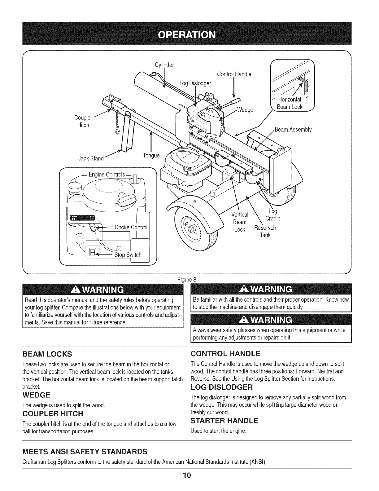
Readthis operator'smanualandthe safetyrulesbeforeoperating
yourlogsplitter.Comparethe illustrationsbelowwithyourequipment
to familiarizeyourselfwiththe locationof variouscontrolsandadjust-
ments.Savethis manualfor futurereference.
ure8
Befamiliarwithall the controlsandtheir properoperation.Knowhow
to stopthe machineanddisengagethemquickly.
Alwayswear safetyglasseswhenoperatingthisequipmentorwhile
performinganyadjustmentsor repairson it.
BEAM LOCKS
Thesetwolocksare usedto securethe beamin the horizontalor
theverticalposition.The verticalbeamlockis locatedonthe tanks
bracket.The horizontalbeamlockis locatedonthe beamsupportlatch
bracket.
WEDGE
Thewedgeis usedto splitthe wood.
COUPLER HITCH
Thecouplerhitchis at theend of the tongueandattachesto a a tow
ballfor transportationpurposes.
CONTROL HANDLE
The ControlHandleis usedto movethe wedgeupanddownto split
wood.Thecontrolhandlehas threepositions;Forward,Neutraland
Reverse.Seethe Usingthe LogSplitterSectionfor instructions.
LOG DISLODGER
The logdislodgeris designedto removeany partiallysplitwoodfrom
the wedge.Thismayoccurwhilesplittinglargediameterwoodor
freshlycutwood.
STARTER HANDLE
Usedto startthe engine.
MEETS ANSI SAFETY STANDARDS
CraftsmanLogSplittersconformto the safetystandardof the AmericanNationalStandardsInstitute(ANSI).
10
TONGUE
Thetongueis usedto attachto a towingvehiclefor transportation.
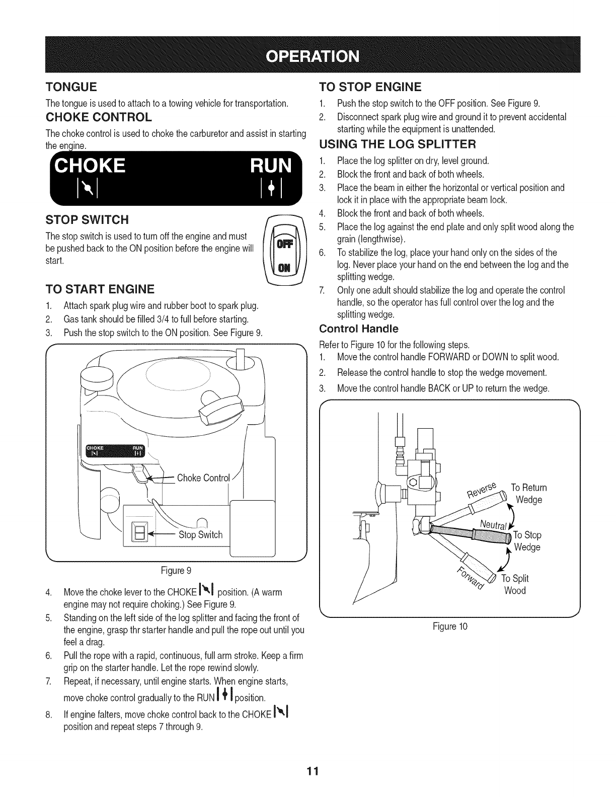
CHOKE CONTROL
Thechokecontrolis usedto chokethe carburetorandassistinstarting
the encinc.
STOP SWITCH
Thestopswitchis usedto turnoff the engineandmust
bepushedbackto the ON positionbeforethe enginewill
start.
TO START ENGINE
1. Attachsparkplugwireand rubberbootto sparkplug.
2. Gastankshouldbefilled 3/4 to full beforestarting.
3. Pushthe stopswitchto the ONposition.See Figure9.
ChokeControlt
_Stop Switch
Figure9
4. Movethe chokeleverto the CHOKEI",1position.(A warm
enginemaynot requirechoking.)SeeFigure9.
5. Standingonthe left sideof the log splitterandfacingthe frontof
the engine,graspthr starterhandleandpullthe ropeoutuntil you
feela drag.
6. Pullthe ropewitha rapid,continuous,full armstroke.Keepa firm
griponthe starterhandle.Letthe roperewindslowly.
7. Repeat,if necessary,untilenginestarts.Whenenginestarts,
movechokecontrolgraduallyto the RUN'__ I position.
8. If enginefalters,movechokecontrolbackto the CHOKEI_-I
positionandrepeatsteps7through9.
TO STOP ENGINE
1. Pushthe stopswitchto the OFFposition.SeeFigure9.
2. Disconnectsparkplugwireandgroundit to preventaccidental
startingwhilethe equipmentis unattended.
USING THE LOG SPLITTER
1. Placethe logsplitterondry,levelground.
2. Blockthe frontandbackof bothwheels.
3. Placethe beamineither thehorizontalor verticalpositionand
lockit in placewiththeappropriatebeamlock.
4. Blockthe frontandbackof bothwheels.
5. Placethe logagainstthe endplateandonly splitwoodalongthe
grain(lengthwise).
6. To stabilizethelog, placeyourhandonlyon the sidesof the
log.Neverplaceyourhandonthe endbetweenthe logandthe
splittingwedge.
7. Onlyoneadultshouldstabilizethelog andoperatethe control
handle,so theoperatorhas full controloverthe logandthe
splittingwedge.
Control Handle
Referto Figure10for the followingsteps.
1. Movethe controlhandleFORWARDor DOWNto splitwood.
2. Releasethe controlhandleto stopthe wedgemovement.
3. Movethe controlhandleBACKor UPto returnthe wedge.
I
ToReturn
Wedge
To Stop
_ Wedge
To Split
e" Wood
Figure10
11
Log Dislodger
The logdislodgerisdesignedto removeanypartiallysplitwoodfrom
thewedge.Thismayoccurwhilesplittinglargediameterwoodor
freshlycut wood.
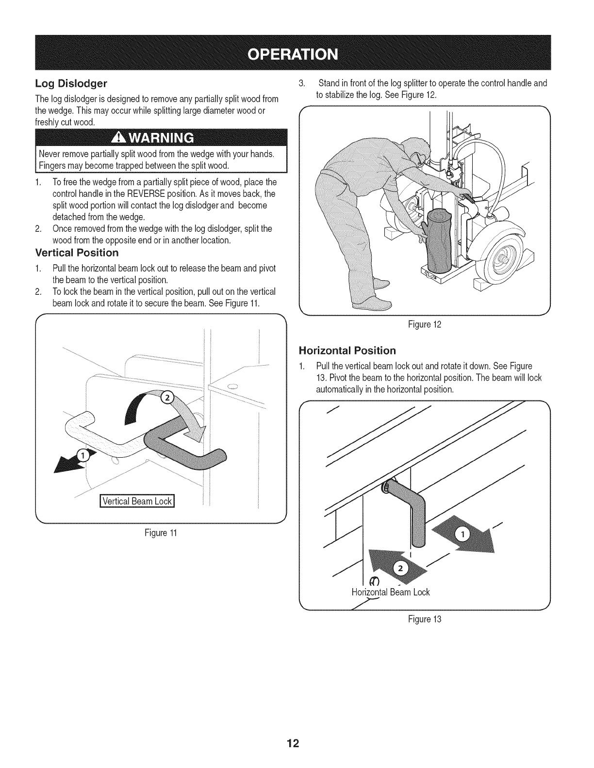
3. Standinfrontof the logsplitterto operatethe controlhandleand
to stabilizethe log. SeeFigure12.
Neverremovepartiallysplitwoodfromthe wedgewithyour hands.
Fingersmaybecometrappedbetweenthe splitwood.
1. Tofreethe wedgefroma partiallysplitpieceof wood,placethe
controlhandlein the REVERSEposition.As it movesback,the
splitwoodportionwillcontactthe logdislodgerand become
detachedfromthe wedge.
2. Onceremovedfromthe wedgewiththe logdislodger,splitthe
woodfromtheoppositeendor inanotherlocation.
Vertical Position
1. Pullthe horizontalbeamlock outto releasethe beamand pivot
the beamto theverticalposition.
2. Tolockthe beaminthe verticalposition,pullout onthe vertical
beamlockandrotateit to securethe beam.SeeFigure11.
IVerticalBeamLockI
Figure11
Figure12
Horizontal Position
1. Pullthe verticalbeamlockout androtateit down.SeeFigure
13.Pivotthe beamto the horizontalposition.Thebeamwill lock
automaticallyinthe horizontalposition.
HorizontalBeamLock
Figure13
12
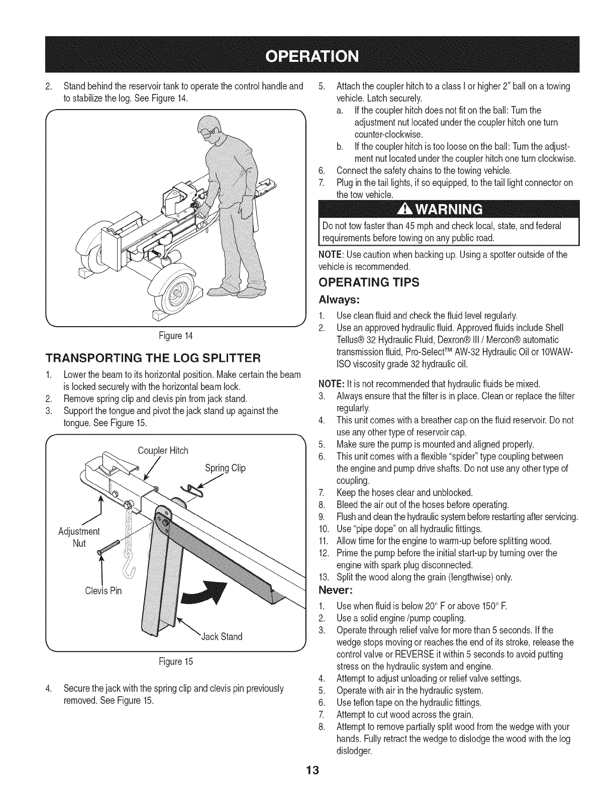
.Standbehindthe reservoirtankto operatethe controlhandleand
to stabilizethe log,See Figure14,
5. Attachthe couplerhitchto a class I or higher2" ballona towing
vehicle.Latchsecurely.
a. Ifthe couplerhitchdoes notfit onthe ball: Turnthe
adjustmentnut locatedunderthe couplerhitchoneturn
counter-clockwise.
b. Ifthe couplerhitchis too looseon the ball:Turntheadjust-
mentnut locatedunderthe couplerhitchoneturnclockwise.
6. Connectthe safetychainsto the towingvehicle.
7. Plugin thetail lights,if so equipped,to the tail light connectoron
the towvehicle.
Figure14
TRANSPORTING THE LOG SPLITTER
1. Lowerthe beamto its horizontalposition.Makecertainthe beam
is lockedsecurelywiththe horizontalbeamlock.
2. Removespringclip andclevispinfromjackstand.
3. Supportthe tongueandpivotthe jackstandupagainstthe
tongue.SeeFigure15.
CouplerHitch
Spritg Clip
.
Figure15
Securethejack withthe springclipand clevispinpreviously
removed.See Figure15.
Donot towfasterthan 45mph andchecklocal,state,and federal
requirementsbeforetowingonany public road.
NOTE:Usecautionwhenbackingup. Usinga spotteroutsideof the
vehicleis recommended.
OPERATING TIPS
Always:
1. Usecleanfluid andcheckthefluid levelregularly.
2. Usean approvedhydraulicfluid.ApprovedfluidsincludeShell
Tellus®32 HydraulicFluid,Dexron®III/Mercon®automatic
transmissionfluid,Pro-SelectTM AW-32HydraulicOilor 10WAW-
ISOviscositygrade32 hydraulicoil.
NOTE:It is not recommendedthathydraulicfluidsbemixed.
3. Alwaysensurethatthe filteris in place.Cleanor replacethe filter
regularly.
4. Thisunit comeswitha breathercap onthe fluid reservoir.Do not
useanyothertypeof reservoircap.
5. Makesurethe pumpis mountedandalignedproperly.
6. Thisunit comeswitha flexible"spider"typecouplingbetween
the engineandpumpdriveshafts. Donot useany othertypeof
coupling.
7. Keepthe hosesclearand unblocked.
8. Bleedthe airout of the hosesbeforeoperating.
9. Flushandcleanthehydraulicsystembeforerestartingafterservicing.
10. Use"pipedope"onall hydraulicfittings.
11. Allowtimefor the engineto warm-upbeforesplittingwood.
12. Primethe pumpbeforethe initial start-upby turningoverthe
enginewith sparkplugdisconnected.
13. Splitthewood alongthe grain(lengthwise)only.
Never:
1. Usewhenfluid is below20oF orabove 150oE
2. Usea solidengine/pumpcoupling.
3. Operatethroughreliefvalvefor morethan5 seconds.If the
wedgestopsmovingor reachesthe endof its stroke,releasethe
controlvalveor REVERSEit within5 secondsto avoidputting
stressonthe hydraulicsystemandengine.
4. Attemptto adjustunloadingor reliefvalvesettings.
5. Operatewithair inthe hydraulicsystem.
6. Useteflontape onthe hydraulicfittings.
7. Attemptto cutwoodacrossthe grain.
8. Attemptto removepartiallysplitwoodfromthe wedgewithyour
hands.Fullyretractthewedgeto dislodgethe woodwiththe log
dislodger.
13
Do notat any timemakeanyadjustmentswithoutfirststopping
theengine,disconnectingsparkplugwire andgroundingit against
theengine.Alwayswearsafetyglassesduringoperationor while
_performng anyadjustmentsor repars.
WEDGE ASSEMBLY ADJUSTMENT
As normalwearoccursandthereisexcessive"play"betweenthe
wedgeand beam,adjustthe boltsonthe sideof the wedgeassembly
to eliminateexcessspacebetweenthe wedgeandthe beam.
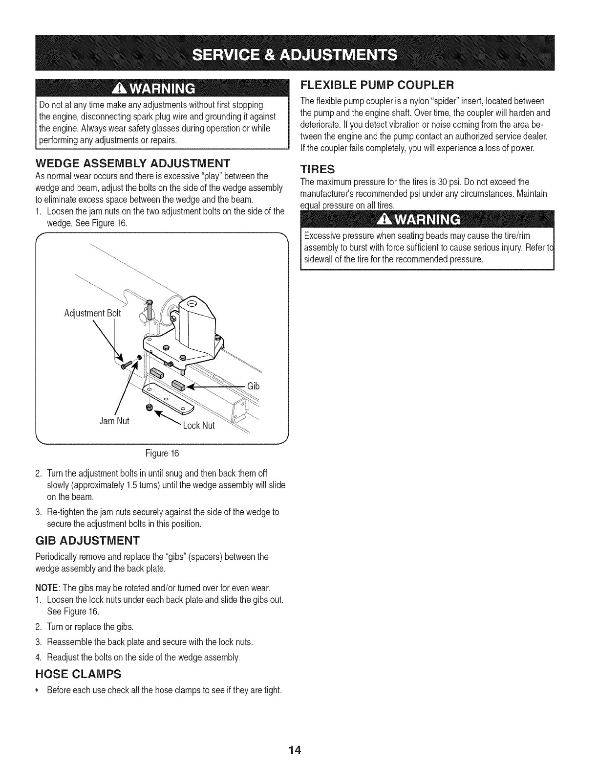
1. Loosenthejam nutson the twoadjustmentboltson the sideof the
wedge.SeeFigure16.
AdjustmentBolt
Jam Nut 'LockNut
Gib
FLEXIBLE PUMP COUPLER
Theflexiblepumpcoupleris a nylon"spider"insert,locatedbetween
the pumpand theengineshaft.Overtime,the couplerwill hardenand
deteriorate.Ifyou detectvibrationor noisecomingfromthe areabe-
tweenthe engineandthe pumpcontactanauthorizedservicedealer.
If thecouplerfailscompletely,you willexperiencea lossof power.
TIRES
The maximumpressurefor thetiresis 30psi.Do not exceedthe
manufacturer'srecommendedpsi underanycircumstances.Maintain
Excessivepressurewhen seatingbeadsmaycausethe tire/rim
assemblyto burstwithforcesufficientto causeseriousinjury.Refertc
sidewallof the tire forthe recommendedpressure.
Figure16
.Turnthe adjustmentboltsinuntil snugandthenbackthemoff
slowly(approximately1.5turns)untilthe wedgeassemblywill slide
onthe beam.
3. Re-tightenthe jam nutssecurelyagainsttheside of the wedgeto
securethe adjustmentboltsin thisposition.
GIB ADJUSTMENT
Periodicallyremoveandreplacethe"gibs"(spacers)betweenthe
wedgeassemblyandthe backplate.
NOTE:Thegibs maybe rotatedand/orturnedoverfor evenwear.
1. Loosenthe locknutsundereach backplateand slidethegibs out.
SeeFigure16.
2. Turnor replacethe gibs.
3. Reassemblethe backplateandsecurewiththe locknuts.
4. Readjusttheboltson the sideof the wedgeassembly.
HOSE CLAMPS
•Beforeeach usecheckallthe hoseclampsto see if theyaretight.
14
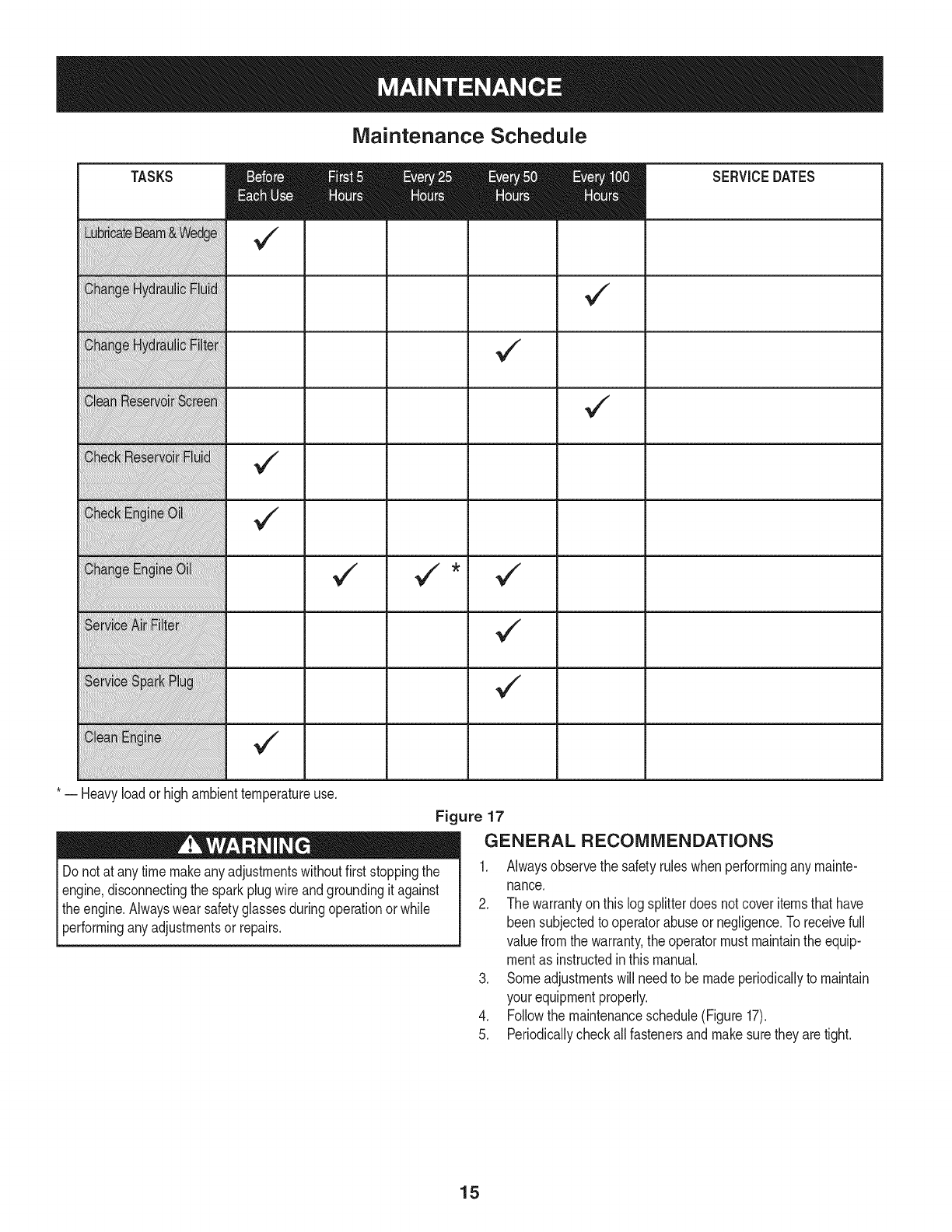
Maintenance Schedule
TASKS
¢"
* -- Heavyloador highambienttemperatureuse.
Figure 17
SERVICEDATES
GENERAL RECOMMENDATIONS
Do notat any timemakeanyadjustmentswithoutfirststoppingthe
engine,disconnectingthe sparkplugwire andgroundingit against
theengine.Alwayswearsafetyglassesduringoperationor while
performinganyadjustmentsor repairs.
1. Alwaysobservethe safetyruleswhenperformingany mainte-
nance.
2. The warrantyonthis logsplitterdoesnotcoveritemsthathave
beensubjectedto operatorabuseor negligence.Toreceivefull
valuefromthe warranty,the operatormust maintainthe equip-
mentas instructedin thismanual.
3. Someadjustmentswill needto bemadeperiodicallyto maintain
yourequipmentproperly.
4. Followthe maintenanceschedule(Figure 17).
5. Periodicallycheckallfastenersandmakesuretheyaretight.
15

HYDRAULIC FLUID AND iNLET FILTER
Stopthe engineandrelievehydraulicsystempressurebeforechang-
ingor adjustingfittings,hoses,tubing,or othersystemcomponents.
Checkthehydraulicfluid levelin the logsplitterreservoirtankbefore
eachuse.Maintainthe fluid levelwithinthe rangespecifiedon the
dipstickat alltimes.
Changethe hydraulicfluid inthe reservoirevery100hoursof opera-
tion.Followthe stepsbelow:
1. Disconnectthe suctionhosefromthe bottomof the reservoirtank.
2. Carefullyunthreadthe inletfilterandclean it withpenetratingoil.
SeeFigure18.
f .......
/
Figure18
3. Allowthefluid to drainintoa suitablecontainer.
4. Reinsertthe filterandrefillthe reservoir.Approvedfluidsinclude
ShellTellus®32 HydraulicFluid,Dexron®III /Merconautomatic
transmissionfluid,Pro-SelectTM AW-32HydraulicOil or IOWAW-
ISOviscositygrade32 hydraulicoil.
5. Maintainthe fluid levelwithinthe rangespecifiedon the dipstick
at alltimes.
NOTE:Alwaysdisposeof usedhydraulicfluidandengineoil at
approvedrecyclingcentersonly.
Contaminantsin fluidmaydamagethe hydrauliccomponents.Flushing
the reservoirtankandhoseswithkerosenewheneverserviceis
performedonthe tank, hydraulicpumpor valveis recommended.Any
repairto the hydrauliccomponentsshouldbe performedby a Sears
ServiceCenter.
BEAM AND SPLITTING WEDGE
Beforeeachuse,lubricateboth sidesof the beam(whereit comesinto
contactwiththe splittingwedge)withengineoil. The wedgeplateon
the log splitteris designedsothe gibs onthe sideof thewedgeplate
can be removedandrotatedand/or turnedoverfor evenwear.
Makecertainto readjusttheadjustmentboltsso the wedgemoves
freely,butno excessspaceexistsbetweenthe wedgeplateandthe
beam.
ENGINE
Check Engine Oil
1. Stoptheengineandwait severalminutesbeforecheckingtheoil
level.
2. Removethe oilfill dipstick.
3. Checkthe oillevelon the dipstick.Withthe engineon level
ground,theoil mustbeto the FULLmarkon thedipstick.
4. Replacethe dipstickandtighten.
Changing Engine Oil
Referto anauthorizedSearsServiceCenter.
Service Air Filter
The airfilterpreventsdamagingdirt,dust, etc.,fromenteringthe
carburetorandbeingforcedintothe engineandis importantto engine
lifeand
Neverrunthe enginewithoutanaircleanercompletelyassembled.
Servicethecartridgeevery25operatinghoursoreveryseason.
Servicethecartridgemoreoftenunderdusty conditions.
To Service Air Filter
.
2.
Loosentheair filtercoverscrew,butdo not removethe screw
fromthe cover.Swingthecoverdownto removefromthe hinge.
Inspectthe filterfor discolorationordirt accumulation.Ifeither is
present,proceedas follows:
a. Cleanthe insideof compartmentandcoverthoroughlyand
removethe cartridge.
b. Reassemblethe newcartridgein the compartment.Swingthe
coverdownandtightenthe screwloosenedearlier.
Temperatureof mufflerandnearbyareasmay exceed150° F(65°C).
Avoidtheseareas.
Useextremecautionwhen workingwith kerosene.It is anextremely
flammablefluid.
Hydraulic Filter
Changethe hydraulicfilterevery50 hoursof operation.Useonly a 10
micronhydraulicfilter.Orderpart number723-0405. 16
Service Spark Plug
1. Cleanthe sparkplugandresetthe gapto .030"at leastonce a
seasonorevery50hoursof operation.
2. Cleantheareaaroundthe sparkplug. Removeandinspectthe
sparkplug.
3. Replacethe sparkplugif the electrodesare pitted,burnedorthe
porcelainis cracked.
NOTE:Contacta SearsPartsandRepairCenteror 1-800-4-MY-
HOME®for a replacementsparkplug,Champion®partnumber
RJ19LM.
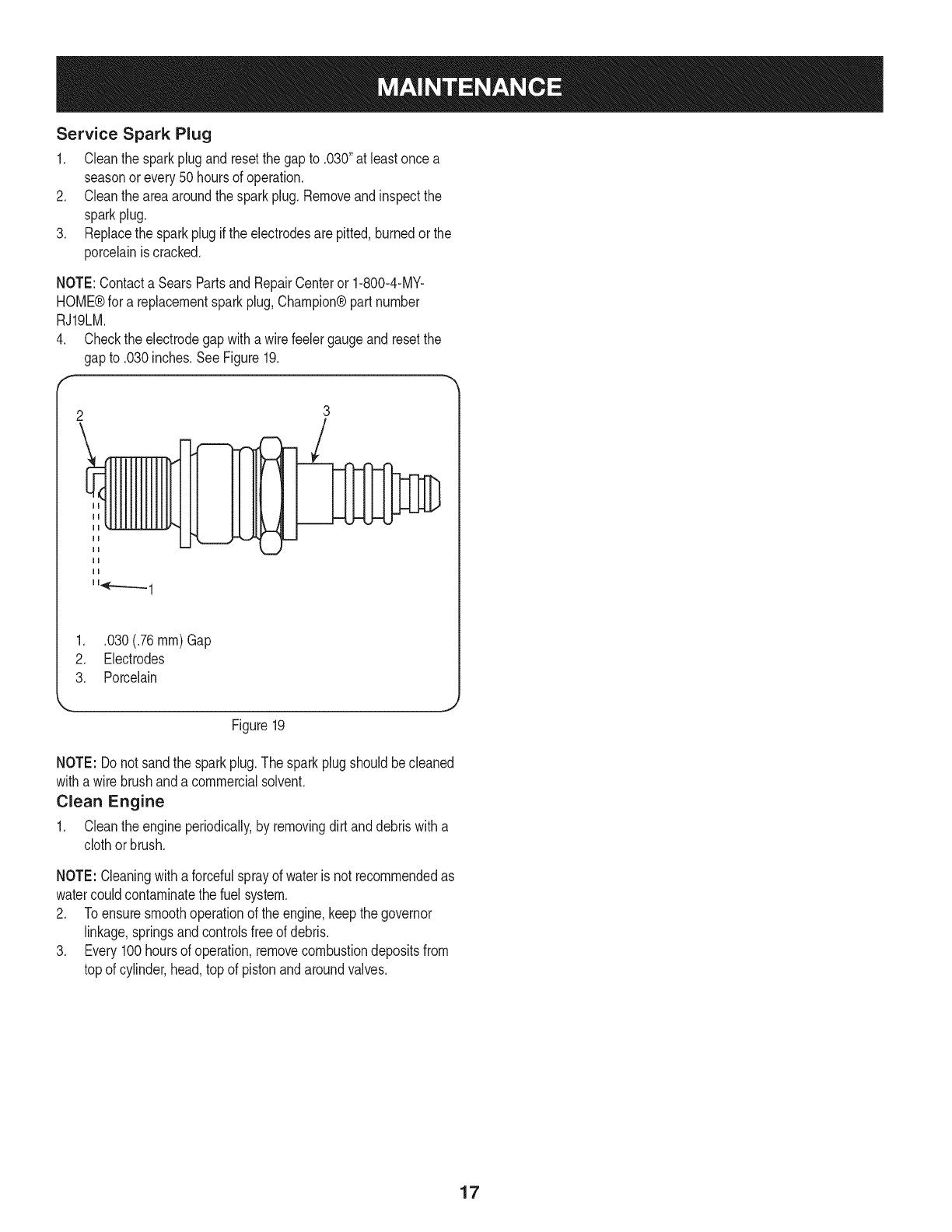
4. Checkthe electrodegapwitha wirefeelergaugeand resetthe
gapto .030inches.SeeFigure19.
2
\
mm
ii
114r-..-_._.1
3
1. .030(.76 ram) Gap
2. Electrodes
3. Porcelain
Figure19
NOTE: Donot sandthe sparkplug.The sparkplugshouldbecleaned
witha wirebrushanda commercialsolvent.
Clean Engine
1. Cleantheengineperiodically,by removingdirt anddebriswitha
clothorbrush.
NOTE: Cleaningwitha forcefulsprayof wateris not recommendedas
watercouldcontaminatethe fuel system.
2. Toensuresmoothoperationof theengine,keepthe governor
linkage,springsandcontrolsfreeof debris.
3. Every100hoursof operation,removecombustiondepositsfrom
topof cylinder,head,top of pistonandaroundvalves.
17
Prepareyour logsplitterfor storageat the endof the seasonor if the
logsplitterwill not beusedfor 30daysor more.
Neverstorethe machinewithfuelin thefuel tankinsideof building
wherefumesmayreachanopenflameor sparkor whereignition
sourcesarepresentsuchas hotwaterand spaceheaters,furnaces,
clothesdyers,stoves,electricmotors,etc.
NOTE:A yearlycheck-upby yourlocalSearsservicecenteris a good
wayto ensureyourlog splitterwill providethe maximumperformance
nextseason.
LOG SPLITTER
1. Cleanthe logsplitterthoroughly.
2. Wipethe logsplitterwithanoiledragto preventrust,especially
onthe wedgeandthe beam.
ENGINE
NOTE: Itis importantto preventgumdepositsfromformingin the
essentialfuel systempartssuchas the carburetor,fuelfilter,fuel hose
ortankduringstorage.Also,alcoholblendedfuels (calledgasoholor
usingethanolor methanol)can attractmoisturewhichleadsto separa-
tionandformationof acidsduringstorage.Acidicgascan damagethe
fuel systemof anenginewhile instorage.
1. Drainthe fueltankby runningthe engineuntilthe fuel linesand
carburetorareempty.Alwaysdrainthe fuel intoan approved
containeroutdoorsawayfromopenflame.Besurethe engineis
cool.Do notsmokewhile handlingthe fuel.
FUEL STABILIZER
NOTE: Fuelstabilizeris anacceptablealternativein minimizingthe
formationof fuel gumdepositsduringstorage.
Pleasefollowthe instructionsbelowfor storingyourlogsplitterwith
fuel andstabilizerinthe engine:
1. Addstabilizerto the gasolinein the fueltankor storagecontainer.
Alwaysfollowthe mixratiofoundonthe stabilizercontainer.
2. Runtheengineat least10minutesafteraddingstabilizerto allow
the stabilizerto reachthe carburetor.
NOTE: Do notdrainthe gastankandcarburetorif usingfuelstabilizer.
Drainall the oilfromthe crankcase(thisshouldbedoneafterthe
enginehasbeenoperatedand is stillwarm)and refillthecrankcase
withfreshoil.
OTHER
• Donot storethe gasolinefromoneseasonto another.
• Replaceyourgasolinecan if it startsto rust.
Storethe logsplitterin a clean,dry area.Do not storeit nextto
any corrosivematerials,suchas fertilizer.
• Wipethe equipmentwithan oiledragto preventrust.
NOTE: Neveruse engineorcarburetorcleanerproductsinthe fuel
tankor permanentdamagemayoccur.Usefreshfuel nextseason.
2. Removethe sparkplug,pourapproximately1/2oz.of engineoil
intocylinderandcrankit slowlyto distributetheoil.
3. Replacethe sparkplug.
18

19
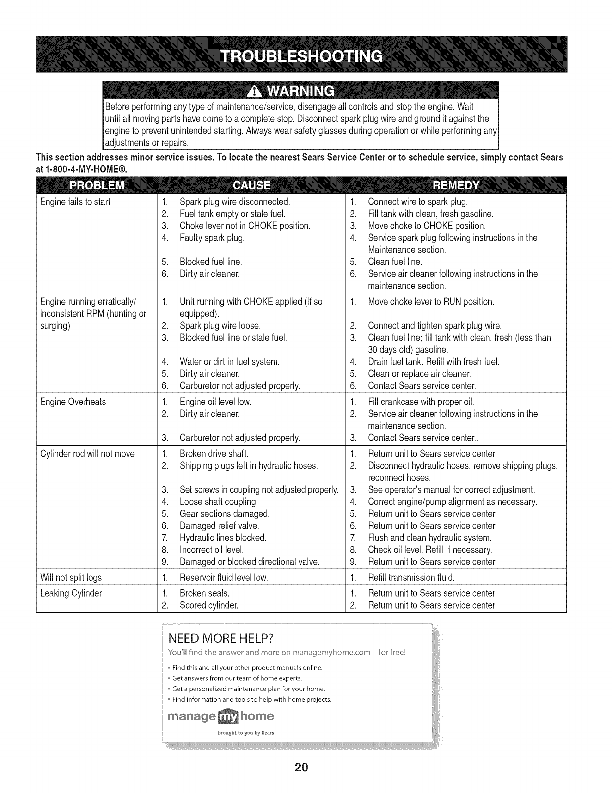
Beforeperformingany typeof maintenance/service,disengageallcontrolsandstoptheengine.Wait
untilall movingpartshavecometo a completestop.Disconnectsparkplugwire andgroundit againstthe
engineto preventunintendedstarting.Alwayswearsafetyglassesduringoperationor whileperformingany
adjustmentsor repars.
Thissectionaddresses minorserviceissues.Tolocatethe nearest Sears Service Centeror to scheduleservice,simplycontactSears
at 1-800-4-MY-HOME®.
1. Sparkplugwire disconnected.
2. Fueltankemptyor stalefuel.
3. Chokelevernot inCHOKEposition.
4. Faultysparkplug.
Enginefailsto start
Enginerunningerratically/
inconsistentRPM(huntingor
surging)
EngineOverheats
Cylinderrodwill not move
5. Blockedfuel line.
6. Dirtyair cleaner.
1. UnitrunningwithCHOKEapplied(if so
equipped).
2. Sparkplugwire loose.
3. Blockedfuel lineor stalefuel.
4. Waterordirt in fuel system.
5. Dirtyair cleaner.
6. Carburetornot adjustedproperly.
1. Engineoillevellow.
2. Dirtyair cleaner.
3. Carburetornot adjustedproperly.
1. Brokendriveshaft.
2. Shippingplugsleft in hydraulichoses.
3. Setscrewsincouplingnotadjustedproperly.
4. Looseshaftcoupling.
5. Gearsectionsdamaged.
6. Damagedreliefvalve.
7. Hydrauliclines blocked.
8. Incorrectoil level.
9. Damagedor blockeddirectionalvalve.
1. Reservoirfluid levellow.
1. Connectwireto sparkplug.
2. Filltankwithclean,freshgasoline.
3. Movechoketo CHOKEposition.
4. Servicesparkplugfollowinginstructionsinthe
Maintenancesection.
5. Cleanfuel line.
6. Serviceaircleanerfollowinginstructionsin the
maintenancesection.
1. Movechokeleverto RUNposition.
2. Connectandtightensparkplugwire.
3. Cleanfuel line; fill tankwithclean,fresh(lessthan
30daysold)gasoline.
4. Drainfueltank. Refillwithfreshfuel.
5. Cleanor replaceair cleaner.
6. ContactSearsservicecenter.
1. Fillcrankcasewith properoil.
2. Serviceaircleanerfollowinginstructionsin the
maintenancesection.
3. ContactSearsservicecenter..
1. Returnunitto Searsservicecenter.
2. Disconnecthydraulichoses,removeshippingplugs,
reconnecthoses.
3. Seeoperator'smanualforcorrectadjustment.
4. Correctengine/pumpalignmentas necessary.
5. Returnunitto Searsservicecenter.
6. Returnunitto Searsservicecenter.
7. Flushandcleanhydraulicsystem.
8. Checkoil level.Refillif necessary.
9. Returnunitto Searsservicecenter.
Will not splitlogs 1. Refilltransmissionfluid.
LeakingCylinder 1. Brokenseals. 1. Returnunitto Searsservicecenter.
2. Scoredcylinder. 2. Returnunitto Searsservicecenter.
NEED MORE HELP?
Yo_iIl lira(/the answer and more on managemyBome corn - I:o_fle!!
Find this and all your other product manuals online,
Get answers from our team of home experts,
Get a personalized maintenance plan for your home.
Find information and tools to help with home projects.
manage _ home
b_:ought to you by Sea_s
2O
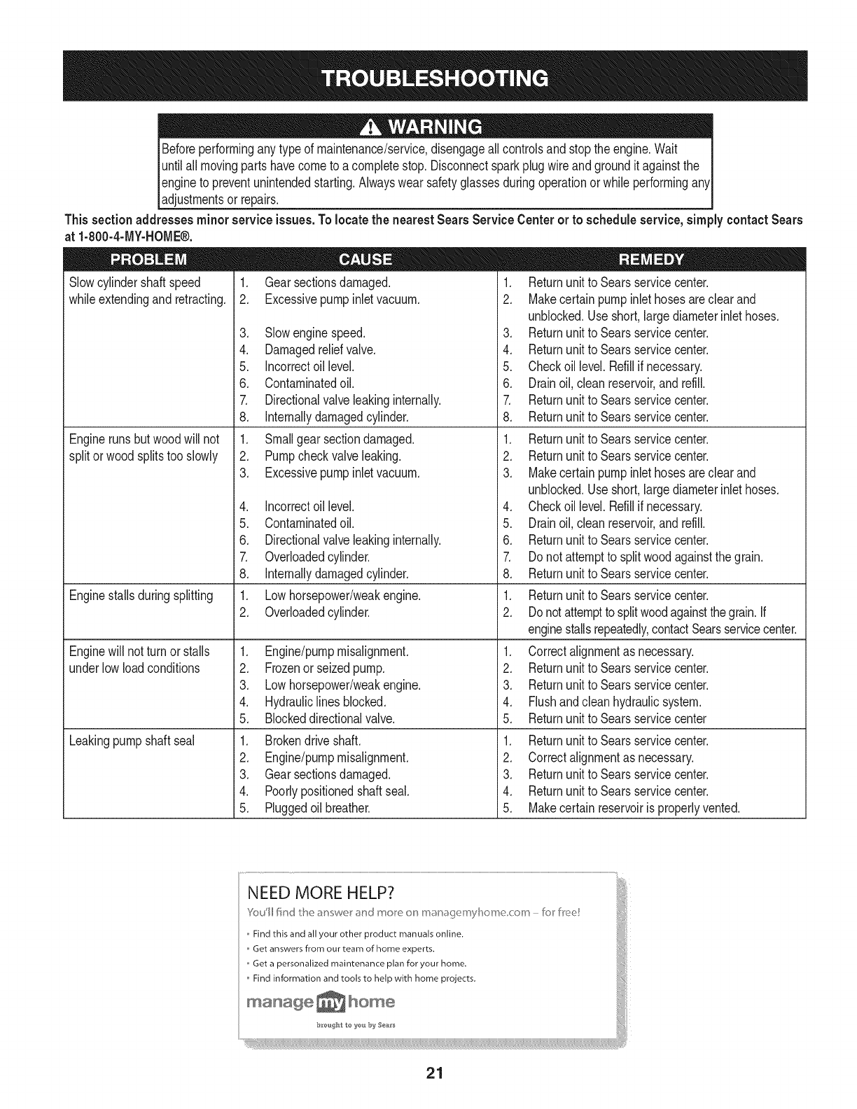
Beforeperformingany typeof maintenance/service,disengageallcontrolsandstoptheengine.Wait I
untilall movingpartshavecometo a completestop.Disconnectsparkplugwire andgroundit againstthe I
engineto preventunintendedstarting.Alwayswearsafetyglassesduringoperationor whileperforminganyI
[adjustmentsor repars.
Thissection addresses minorserviceissues.Tolocate the nearest Sears Service Centeror to scheduleservice,simplycontact Sears
at 1-800-4-MY-HOME®.
Slowcylindershaftspeed
whileextendingand retracting.
Engineruns butwoodwill not
splitor woodsplitstoo slowly
Enginestallsduringsplitting
Enginewill notturn or stalls
underlowloadconditions
Leakingpumpshaft seal
1. Gearsectionsdamaged.
2. Excessivepumpinletvacuum.
3. Slowenginespeed.
4. Damagedreliefvalve.
5. Incorrectoil level.
6. Contaminatedoil.
7. Directionalvalveleakinginternally.
8. Internallydamagedcylinder.
1. Smallgear sectiondamaged.
2. Pumpcheckvalveleaking.
3. Excessivepumpinletvacuum.
4. Incorrectoil level.
5. Contaminatedoil.
6. Directionalvalveleakinginternally.
7. Overloadedcylinder.
8. Internallydamagedcylinder.
1. Lowhorsepower/weakengine.
2. Overloadedcylinder.
1. Engine/pumpmisalignment.
2. Frozenor seizedpump.
3. Lowhorsepower/weakengine.
4. Hydrauliclines blocked.
5. Blockeddirectionalvalve.
1. Brokendriveshaft.
2. Engine/pumpmisalignment.
3. Gearsectionsdamaged.
4. Poorlypositionedshaftseal.
5. Pluggedoil breather.
.
2.
.
4.
5.
6.
7.
8.
1.
2.
3.
.
5.
6.
7.
8.
1.
2.
.
2.
3.
4.
5.
1.
2.
3.
4.
5.
Returnunitto Searsservicecenter.
Makecertainpump inlethosesareclearand
unblocked.Useshort,largediameterinlet hoses.
Returnunitto Searsservicecenter.
Returnunitto Searsservicecenter.
Checkoil level.Refillif necessary.
Drainoil,clean reservoir,andrefill.
Returnunitto Searsservicecenter.
Returnunitto Searsservicecenter.
Returnunitto Searsservicecenter.
Returnunitto Searsservicecenter.
Makecertainpump inlethosesareclearand
unblocked.Useshort,largediameterinlet hoses.
Checkoil level.Refillif necessary.
Drainoil,clean reservoir,andrefill.
Returnunitto Searsservicecenter.
Do notattemptto splitwoodagainstthe grain.
Returnunitto Searsservicecenter.
Returnunitto Searsservicecenter.
Donotattempttosplitwoodagainstthe grain.If
enginestallsrepeatedly,contactSearsservicecenter.
Correctalignmentas necessary.
Returnunitto Searsservicecenter.
Returnunitto Searsservicecenter.
Flushandcleanhydraulicsystem.
Returnunitto Searsservicecenter
Returnunitto Searsservicecenter.
Correctalignmentas necessary.
Returnunitto Searsservicecenter.
Returnunitto Searsservicecenter.
Makecertainreservoiris properlyvented.
21
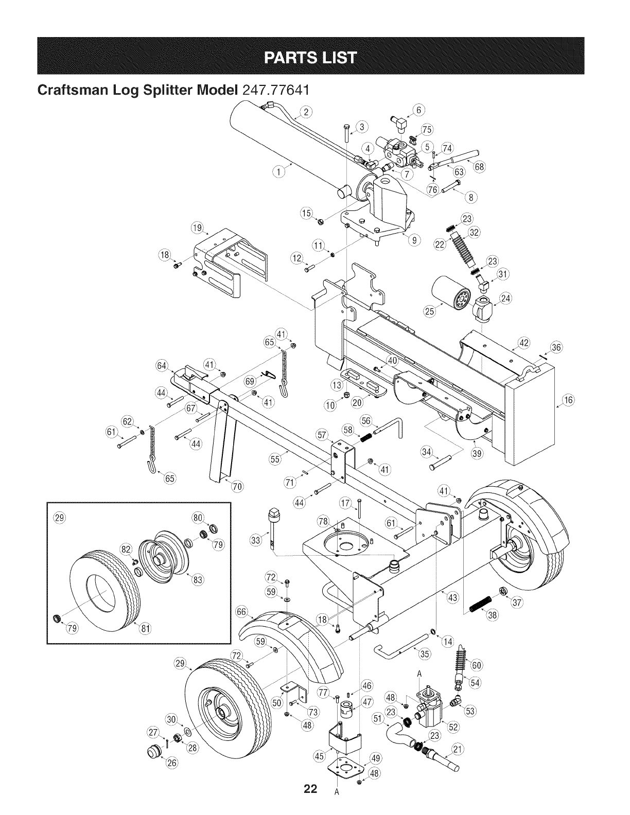
Craftsman Log Splitter Model 247.77641
22 A
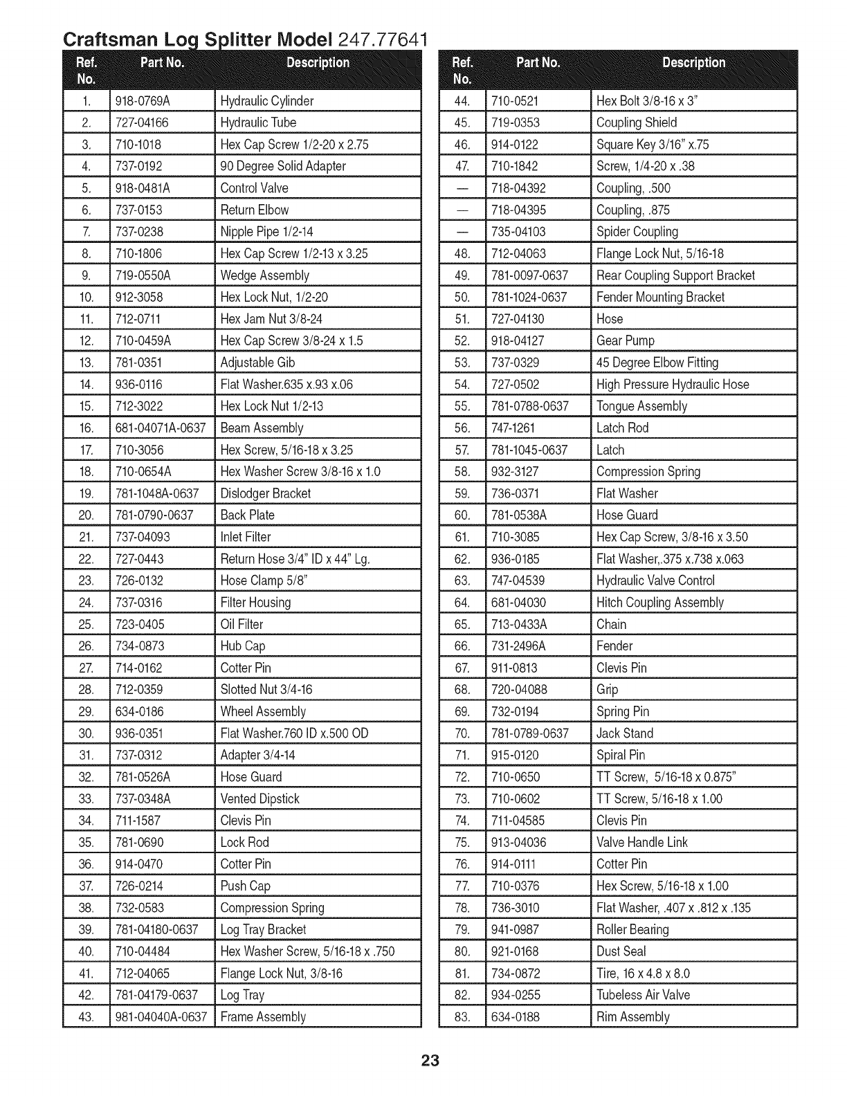
Loc iVlodel 247
918-0769A
727-04166
710-1018
737-0192
918-0481A
737-0153
737-0238
710-1806
719-0550A
912-3058
712-0711
710-0459A
781-0351
936-0116
712-3022
681-04071A-0637
710-3056
710-0654A
781-1048A-0637
781-0790-0637
737-04093
727-0443
726-0132
737-0316
723-0405
734-0873
714-0162
712-0359
634-0186
936-0351
737-0312
781-0526A
737-0348A
711-1587
781-0690
914-0470
726-0214
732-0583
781-04180-0637
710-04484
712-04065
781-04179-0637
981-04040A-0637
HydraulicCylinder
HydraulicTube
HexCapScrew1/2-20x 2.75
90 DegreeSolidAdapter
ControlValve
ReturnElbow
NipplePipe1/2-14
HexCapScrew1/2-13x 3.25
WedgeAssembly
HexLockNut, 1/2-20
HexJamNut3/8-24
HexCapScrew3/8-24 x 1.5
AdjustableGib
FiatWasher.635x.93x.06
HexLockNut1/2-13
BeamAssembly
HexScrew,5/16-18x 3.25
HexWasherScrew3/8-16x 1.0
DislodgerBracket
BackPlate
inlet Filter
ReturnHose3/4" IDx 44" Lg.
HoseClamp5/8"
FilterHousing
Oil Filter
Hub Cap
CotterPin
SlottedNut3/4-16
WheelAssembly
FlatWasher.760IDx.500OD
Adapter3/4-14
HoseGuard
VentedDipstick
ClevisPin
LockRod
CotterPin
PushCap
CompressionSpring
LogTrayBracket
HexWasherScrew,5/16-18x .750
FlangeLockNut,3/8-16
LogTray
FrameAssembly
23
710-0521
719-0353
914-0122
710-1842
718-04392
718-04395
735-04103
712-04063
781-0097-0637
781-1024-0637
727-04130
918-04127
737-0329
727-0502
781-0788-0637
747-1261
781-1045-0637
932-3127
736-0371
781-0538A
710-3085
936-0185
747-04539
681-04030
713-0433A
731-2496A
911-0813
720-04088
732-0194
781-0789-0637
915-0120
710-0650
710-0602
711-04585
913-04036
914-0111
710-0376
736-3010
941-0987
921-0168
734-0872
934-0255
634-0188
HexBolt3/8-16x 3"
CouplingShield
SquareKey3/16"x.75
Screw,1/4-20x .38
Coupling,.500
Coupling,.875
SpiderCoupling
FlangeLockNut,5/16-18
RearCouplingSupportBracket
FenderMountingBracket
Hose
GearPump
45 DegreeElbowFitting
HighPressureHydraulicHose
TongueAssembly
LatchRod
Latch
CompressionSpring
FlatWasher
HoseGuard
HexCap Screw,3/8-16x 3.50
FiatWasher,.375x.738x.063
HydraulicValveControl
HitchCouplingAssembly
Chain
Fender
ClevisPin
Grip
SpringPin
Jack Stand
SpiralPin
TT Screw, 5/16-18x 0.875"
TT Screw,5/16-18x 1.00
ClevisPin
ValveHandleLink
CotterPin
HexScrew,5/16-18x 1.00
FiatWasher,.407x.812x.135
RollerBearing
DustSeal
Tire, 16x 4.8 x 8.0
TubelessAirValve
RimAssembly
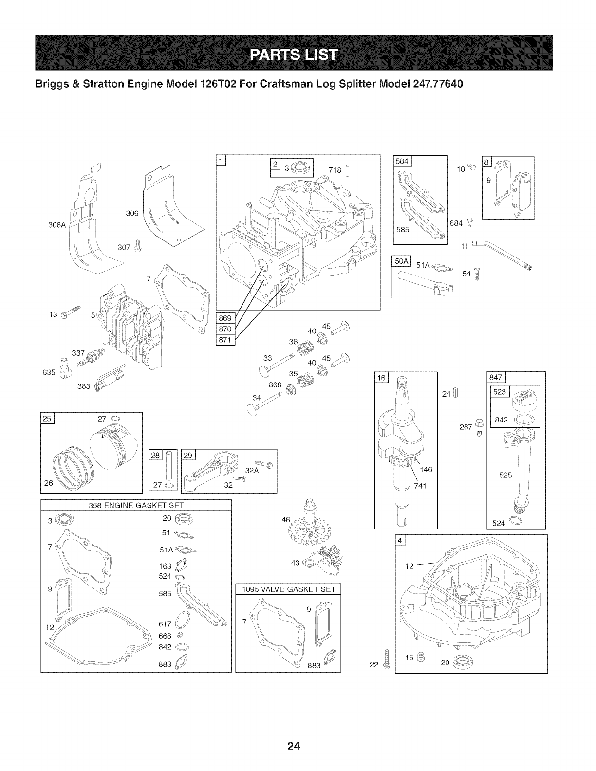
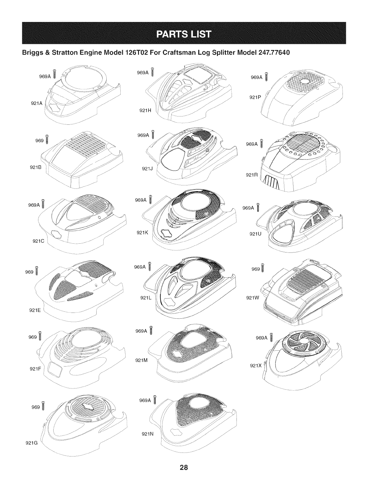
Briggs & Stratton Engine IViodel 126T02 For Craftsman Log Splitter IViodel 247.77640
306A
306
26
3
7
585
32
46
43
1095 VALVE GASKET SET
10_
684 _
L5_ 51Ac(.c 5.o_ 54
1_£1 _4_
842 _-i[_ _
525
524 '\_-_
22
24
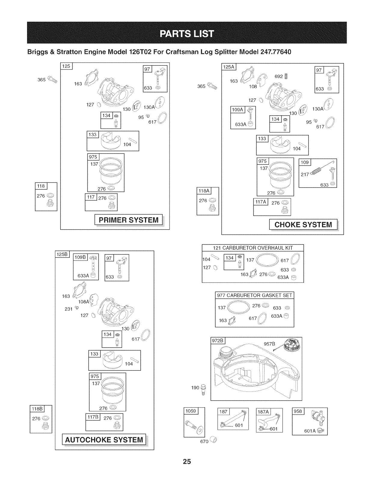
Briggs & Stratton Engine IViodel 126T02 For Craftsman Log Splitter IViodel 247.77640
365 '%.©_ 163
PRIMER SYSTEM
365 ",_
163
127 \p
_J
633A _'_
692
130
276 _s
633 @
276 ¢_i_
CHOKE SYSTEM
633A _:J 1633 I
AUTOC#OKESYSTEa]
1_601
/i_,
670 _
_-6 o
ii_ _
i
601A _
25
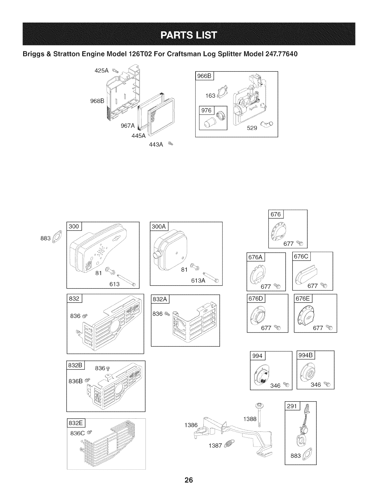
Briggs & Stratton Engine Model 126T02 For Craftsman Log Splitter Model 247.77640
968B
967A
445A
443A _
883
8369_ _
836B_ C_" _/_¢_
B0_
J_G\
613A " ©
|
[ ..... 677 _'_
677 _ 677 _?)
346 _£; 346 _ _"
1388 i
883
26
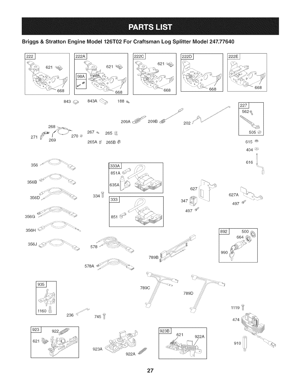
Briggs & Stratton Engine Model 126T02 For Craftsman Log Splitter Model 247.77640
621 621
||
843 <_## 843A < ......
268 _ ....
_:-_ __'" 267
271 _6f_9'%=")' 270'_ 265A_'
356 - _.
356B "_ ......
_ !-_:__..
356D ._ '_<_h
356G _ '"_-_
356H _ ....... _'_'%
356J _ "-'_::: ::::_ _.
1160 _U_
188 %
209A _-_ '
265 _:__
265B
J
209B d_ _'_Z_ 202
334 _
635A 627
347
497 _
J_ XI .--.%: *:-_
578A _..,¢/ _ _._._
789 B _"'_
789D
745 _
923A
621 922A
616
627A
497 _
500
0
1119 ::4
474
910
27
Briggs & Stratton Engine IViodel 126T02 For Craftsman Log Splitter IViodel 247.77640
921A
969
_" //_ 921 P /[
921 H J F/
969A
969 _l
969A
921J /
969A
921K
969A
921 L
969A
969A _
921 R // ,t-_--_-----__.//
969A
921 U
969_
921W
969A
921F
969_
921M
969A
921X
/
921N
28
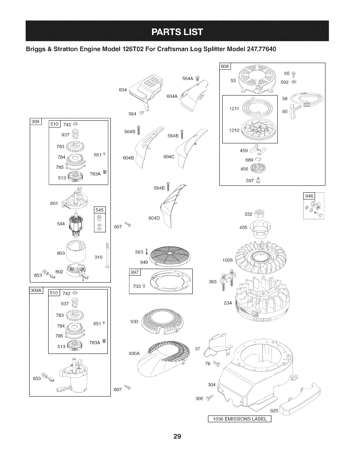
Briggs & Stratton Engine Model 126T02 For Craftsman Log Splitter Model 247.77640
742 _#_;
937
783
651 2
783A @
513
801
544
803 i 310
%
10 I _L_742 '_
937 _-'_
783
651
783A @
513
[
6O4
604A
564B
/
/
6O4B/ /
564B
604C J
697 %
563
949
930
930A
697 %<_
363
37
78
55
1005
23A
1211
1210
U
459 _j
689 dp>
456
597 _
455
I 1036 EMISSIONS LABEL J
29
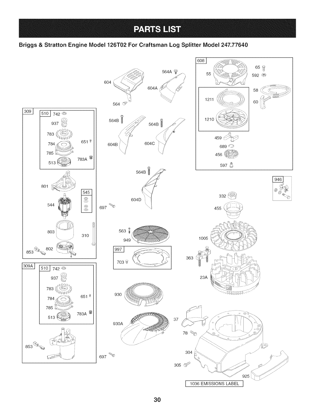
Briggs & Stratton Engine IViodel 126T02 For Craftsman Log Splitter IViodel 247.77640
742 '_r*_
937
783
651 t_
783A @
513
801
544
803
_ 802
853 __. .......
310
651
783A @
513
564 _:_
564B ¢_
604C
564B
55 65?
592 _
1211
1210
58
60
459 L -
, _-
689 _19
f %,
456 J
597 _)
697 _
563
930
363
1005
23A
'\.. J
,'f_. LI2,_
930A
697 _b
37
/,
/
3O4
3O

Briggs
2
3 BS-299819S OilSeal
4 BS-493279 EngineSump
5 BS-691160 CylinderHead
7 BS-692249 CylinderHeadGasket
8 _BS-695250 BreatherAssembly
9 BS-696125 BreatherGasket
10 BS-691125 Screw(BreatherAssembly)
11 BS-6917811 BreatherTube
&Stratton Engine Model 126T02 For Craftsman Log Splitter Model 247.77640
|= o= |= o®
BS-697322 CylinderAssembly BS-690837 Screw(RewindStarter)
BS-399269 Bushing/SealKit 78 BS-691108 Screw(FlywheelGuard)
12 BS-692232 CrankcaseGasket
13 BS-690912 Screw(CylinderHead)
15 BS-691680 OilDrainPlug
16 BS-691455 Crankshaft
20 BS-399781S OilSeal
22 BS-691092 Screw
23A BS-691992 Flywheel
24 _BS222698S FlywheelKey
25 BS-797302 PistonAssembly
26 BS-797304 RingSet
27 BS-691588 PistonPinLock
28 BS_298909 PistonPin
29 BS-797306 ConnectingRod
32 BS-691664 Screw
32A BS-695759 Screw
33 BS-262651S ExhaustValve
34 BS-262652S IntakeValve
35 BS-691270 ValveSpring(Intake)
36 BS-691270 ValveSpring(Exhaust)
37 BS-694086 FlywheelGuard
40 BS-692194 ValveRetainer
43 BS-691997 Governor/OilSlinger
45 BS-690548 ValveTappet
46 BS-691449 Camshaft
31
50A BS-794305 IntakeManifold
51 BS-272199S IntakeGasket
51A BS-794306 IntakeGasket
54 BS-691650 Screw(IntakeManifold)
55 BS-691421 RewindStarterHousing
58 BS-697316 StarterRope
60 BS-281434S StarterRopeGrip
81 BS-691740 MufflerScrewLock
95 BS-691636 Screw(ThrottleValve)
97 BS-493267 ThrottleShaft
98A BS-493280 Idle SpeedKit
104 BS-691242 FloatHingePin
108 BS-691182 ChokeValve
108A BS-795935 ChokeValve
109 BS-494218 ChokeShaft
109A BS-498593 ChokeShaft
109B BS-795936 ChokeShaft
117 BS-498978 MainJet
117A BS-498981 MainJet(Standard)
117B BS-695042 MainJet(Standard)
118 BS-497466 MainJet(HighAltitude)
118A BS-497315 MainJet(HighAItitude)
118B BS-694975 MainJet(HighAItitude)
121 BS-498260 CarburetorOverhaulKit
125 BS-498170 Carburetor(PrimerSystem)
125A BS-792253 Carburetor(ChokeSystem)
125B BS-794304 Carburetor(AutochokeSystem)
127 BS-694468 WelchPlug
130 BS-696564 ThrottleValve
130A BS-691203 ThrottleValve
133 BS-398187 CarburetorFloat
134 BS-398188 Needle/SeatKit
137 BS-693981 FloatBowlGasket
146 BS-690979 TimingKey
163 BS-272653 AirCleanerGasket
187 BS-791766 FuelLine(Cutto RequiredLength)
187A BS-791873 FuelLine(Molded)
188 BS-693399 Screw(ControlBracket)
190 BS-690940 Screw(FuelTank)
202 BS-691829 MechanicalGovernorLink
209A BS-790944 GovernorSpring
217 BS-690354 ChokeReturnSpring
222 BS-790143 ControlBracket(Remote/Manual
Friction)(Primer)
222A BS-692021 ControlBracket(Remote,ChokeA
Matic,NonCompliance)

Briggs & Stratton Engine Model 126T02 For Craftsman Log
|= o =
BS-791128 ControlBracket(FixedSpeed)
222E BS-692982 ControlBracket(ManualFriction,5
PositionManualChoke)
227 BS-690783 GovernorControlLever
231 BS-691636 Screw(ChokeValve)
236 BS-691826 LockoutLink
265 BS-690798 CasingClamp
265A BS-691024 CasingClamp
265B BS-692179 CasingClamp
267 BS-691044 Screw(CasingClamp)
268 BS-691025 ControlWire Casign(Cutto Required
Length)
269 BS-691026 ControlWire (Cutto Required
Length)
270 BS-691027 Nut(ControlWire Casing)
271 BS-691028 ControlLever
276 BS-271716 SealingWasher
287 BS-690940 Screw(DipstickTube)
291 BS-790830 Thermostat
300 BS-692038 Muffler
300A BS-494343S Muffler
304 BS-493294 BlowerHousing
305 BS-691108 Screw(BlowerHousing)
306 BS-690450 CylinderShield
306A BS-790836 CylinderShield
307 BS-690345 Screw(CylinderShield)
309 BS-695550 StarterMotor
310 BS-692327 Bolt(StarterMotor)
332 BS-690662 Nut(Flywheel)
333 BS-802574 MagnetoArmature
333A BS-793353 MagnetoArmature
334 BS-691061 Screw(MagnetoArmature)
337 759-3338 SparkPlug
346 BS-690661 Screw(SparkArrester)
347 BS-691396 RockerSwitch
356 BS-692390 StopWire
356B BS-693010 StopWire
356D BS-496381 StopWire
356G BS-695283 StopWire
356H BS-690791 StopWire
356J BS-691423 StopWire
Splitter Model 247.77640
|= o o
BS-794307 EngineGasketSet
363 BS-19069 FlywheelPuller
365 BS-691688 Screw(Carburetor)
383 BS-89838S SparkPlugWrench
404 BS-690272 Washer(GovernorCrank)
425A BS-690670 Screw(AirCleanerCover)
443A BS-692523 Screw(AirCleanerPrimerBase)
445A BS-491588S AirCleanerFilterCartridge
455 BS-791960 FlywheelCup
456 BS-692299 PawlFrictionPlate
459 BS-281505S RatchetPlate
474 BS-691991 Alternator
497 BS-690664 Screw(StopSwitchBracket)
500 BS-691086 Washer(Key Switch)
505 BS-691251 Nut(GovernorControlLever)
510 BS-795093 StarterDrive
513 BS-692358 DriveClutch
523 BS-499621 Dipstick
524 BS-692296 DipstickTubeSeal
525 BS-495265 DipstickTube
529 BS-691923 Grommet
544 BS-690786 StarterArmature
545 BS-492919 WasherSet
562 BS-92613 Bolt(GovernorControlLever)
563 BS-691138 Screw(DebrisGuardScreen)
564 BS-690664 Screw(ControlCover)
564A BS-691142 Screw(ControlCover)
564B BS-698589 Screw(ControlCover)
578 BS-398153 AssemblyWire
578A BS-696031 AssemblyWire
584 BS-697734 BreatherPassageCover
585 BS-691879 BreatherPassageGasket
592 BS-690800 Nut(RewindStarter)
597 BS-691696 Screw(PawlFrictionPlate)
601 BS-791850 HoseClamp
601A BS-691038 HoseClamp
604 BS-691757 ControlCover
604A BS-691344 ControlCover
604B BS-790703 ControlCover
604C BS-792418 ControlCover
604D BS-793770 ControlCover
32
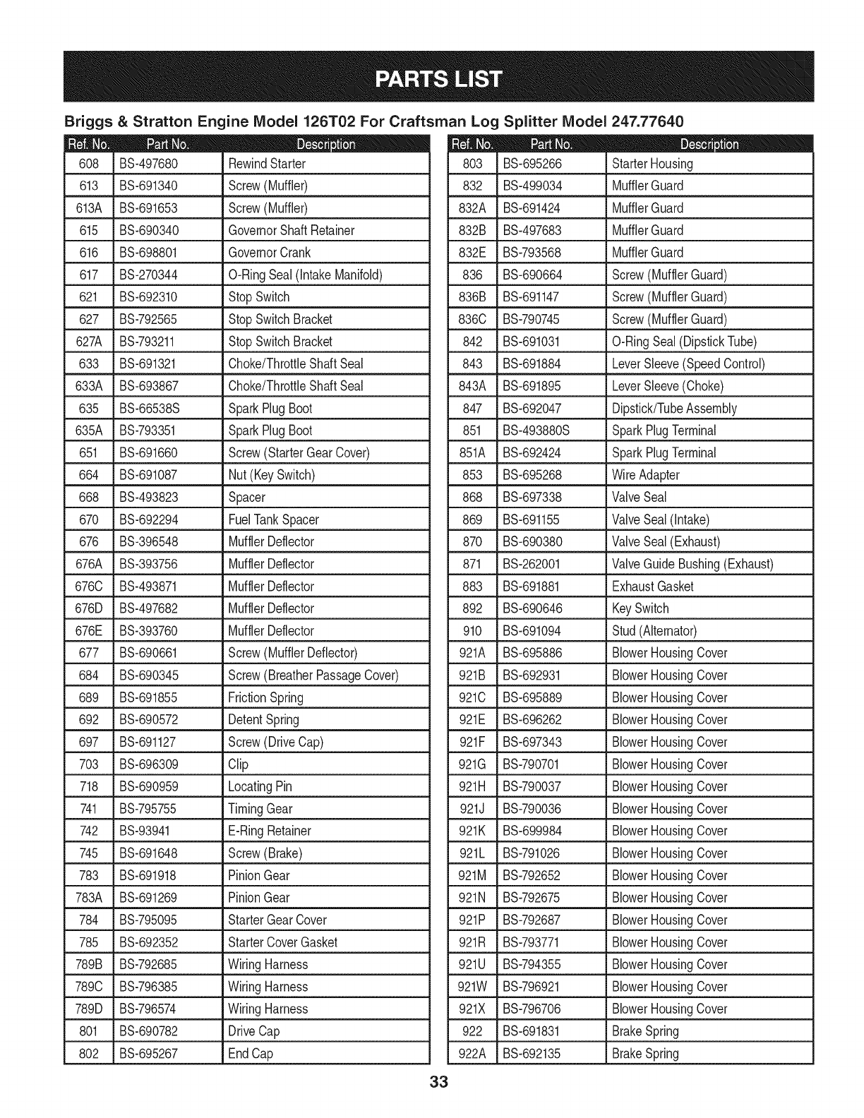
Briggs & Stratton Engine IViodel 126T02 For Craftsman Log Splitter IViodel 247.77640
D = O
BS-497680 RewindStarter
613 ,BS-691340 Screw(Muffler)
613A BS-691653 Screw(Muffler)
615 BS-690340 GovernorShaftRetainer
616 BS-698801 GovernorCrank
617 BS-270344 O-RingSeal(IntakeManifold)
621 , BS-692310 StopSwitch
627 BS-792565 StopSwitchBracket
627A BS-793211 StopSwitchBracket
633 BS-691321 Choke/ThrottleShaftSeal
633A BS-693867 Choke/ThrottleShaftSeal
635 BS-66538S SparkPlugBoot
635A BS-793351 SparkPlugBoot
651 BS-691660 Screw(StarterGearCover)
664 J BS-691087 Nut(Key Switch)
668 BS-493823 Spacer
670 BS-692294 FuelTankSpacer
676 BS-396548 MufflerDeflector
L
676A BS-393756 MufflerDeflector
6760 BS-493871 MufflerDeflector
676D BS-497682 MufflerDeflector
676E BS-393760 MufflerDeflector
677 BS-690661 Screw(MufflerDeflector)
684 BS-690345 Screw(BreatherPassageCover)
689 BS-691855 FrictionSpring
692 _BS690572 DetentSpring
697 BS-691127 Screw(DriveCap)
703 BS-696309 Clip
718 BS-690959 LocatingPin
741 BS-795755 TimingGear
742 BS-93941 E-RingRetainer
745 BS-691648 Screw(Brake)
783 BS-691918 PinionGear
783A BS-691269 PinionGear
784 BS-795095 StarterGearCover
785 BS-692352 StarterCoverGasket
789B BS-792685 WiringHarness
7890 BS-796385 WiringHarness
789D BS-796574 WiringHarness
801 BS-690782 DriveCap
802 BS-695267 EndCap
33
D = O
BS-695266 StarterHousing
832 BS-499034 MufflerGuard
832A BS-691424 MufflerGuard
832B BS-497683 MufflerGuard
832E BS-793568 MufflerGuard
836 BS-690664 Screw(MufflerGuard)
836B BS-691147 Screw(MufflerGuard)
8360 BS-790745 Screw(MufflerGuard)
842 BS-691031 O-RingSeal(DipstickTube)
843 BS-691884 LeverSleeve(SpeedControl)
843A BS-691895 LeverSleeve(Choke)
847 BS-692047 Dipstick/TubeAssembly
851 BS-493880S SparkPlugTerminal
851A BS-692424 SparkPlugTerminal
853 BS-695268 WireAdapter
868 BS-697338 ValveSeal
869 BS-691155 ValveSeal(Intake)
870 BS-690380 ValveSeal(Exhaust)
871 BS-262001 ValveGuideBushing(Exhaust)
883 BS-691881 ExhaustGasket
892 BS-690646 KeySwitch
910 BS-691094 Stud(Alternator)
921A BS-695886 BIowerHousingCover
921B BS-692931 BIowerHousingCover
9210 BS-695889 BIowerHousingCover
921E BS-696262 BIowerHousingCover
921F BS-697343 BIowerHousingCover
921G BS-790701 BIowerHousingCover
921H BS-790037 BIowerHousingCover
921J BS-790036 BlowerHousingCover
921K BS-699984 BIowerHousingCover
921L BS-791026 BIowerHousingCover
921M BS-792652 BIowerHousingCover
921N BS-792675 BIowerHousingCover
921P BS-792687 BIowerHousingCover
921R BS-793771 BIowerHousingCover
921U BS-794355 BIowerHousingCover
921W BS-796921 BIowerHousingCover
921X BS-796706 BIowerHousingCover
922 BS-691831 BrakeSpring
922A BS-692135 BrakeSpring

Briggs & Stratton Engine Model 126T02 For Craftsman Log Splitter
BS-691994 Brake
923A BS-695891 Brake
923 BS-691994 Brake
923A BS-695891 Brake
923B BS-796136 Brake
925 BS-795403 LinkageCover
930 BS-691919 RewindGuard
930A BS-691345 RewindGuard
935 BS-499421 InterlockSwitch
937 BS-691325 StarterSpline
946 BS-691738 RopeStop
949 BS-696306 DebrisScreenGuard
957B BS-699985 FuelTankCap
958 BS-698183 FuelShut Off Valve
966B BS-792040 Air CleanerPrimerBase
967A BS-493537S Pre-CleanerFilter
968B BS-692298 Air CleanerCover
969 BS-690700 Screw(BlowerHousingCover)
969A BS-691138 Screw(BIowerHousingCover)
970 BS-691669 Screw(AirCleanerPrimerBracket)
972B BS-699374 FuelTank
975 BS-493640 FloatBowl
Model 247.77640
|- w o
BS-694395 CarburetorPrimer
977 BS-498261 CarburetorGasketSet
990 BS-691959 KeySet
994 BS-398067 SparkArrestor
994B BS-792245 SparkArrestor
997 BS-696310 DebrisShield
1005 BS-691346 FlywheelFan
1019 BS-694881 LabelKit
1036 -- EmissionsLable
1058 BS-277039 Operator'sManual
1059 BS-692311 Screw/WasherKit
1095 BS-498528 ValveGasketSet
1119 BS-692979 Screw(Alternator)
1160 BS-690345 Screw(InterlockSwitch)
1210 BS-498144 Pulley/SpringAssembly(Pulley)
1211 BS-498144 Pulley/SpringAssembly(Spring)
1319 BS-794467 WarningLabel
1330 BS-270962 RepairManual
1386 BS-790848 AirVane(AutochokeSystem)
1387 BS-790849 AirVaneSpring
1388 BS-790850 Screw(AirVane)
34
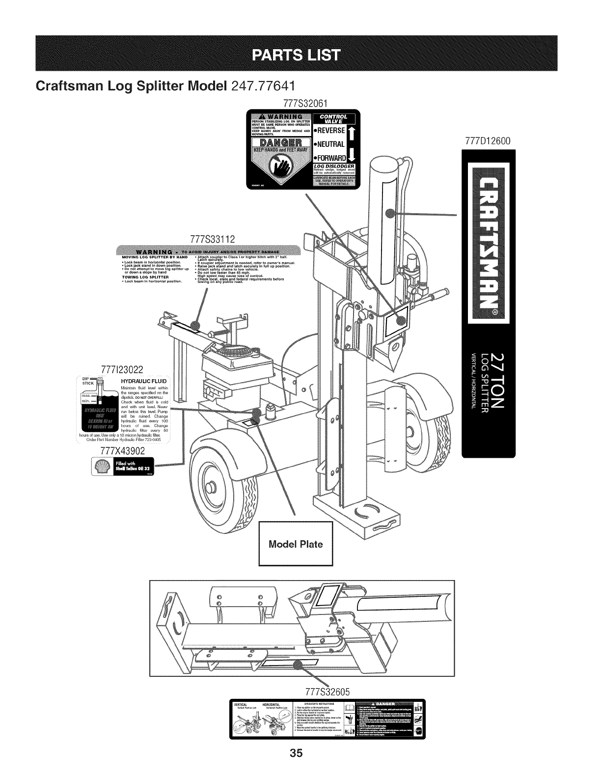
Craftsman Log Splitter Model 247.77641
777S32061
777D12600
777123022
HYDRAULIC FLUID
Maintain fluid bevel within
the r_ges _ecified on the
dipstick. Be NOT OV_:t_F_LH
Check when fluid is cold
and with unit bevel. Never
run below this level Pump
will be ruined. Change
}_/draullo fluid every 100
hours of u_. Change
}_dmullo filter every 5O
beu_s of u_. U_ only a 10 mloron }_/dcaullo filte_
Order P'drt Number NydJ_ul[c Fille r 723-0405
777X43902
Model Plate
© ©
© ©
777S32605
35
Congratulationson makinga smart purchase.YournewCraftsman®
productis designedandmanufacturedfor yearsof dependableopera-
tion.But likeall products,it mayrequirerepairfromtimeto time.That's
whenhavinga RepairProtectionAgreementcan saveyoumoneyand
aggravation.
Here'swhatthe RepairProtectionAgreement*includes:
* Expert service byour 10,000professionalrepairspecialists
* Unlimited service and no charge for partsand laboronall
coveredrepairs
* Product replacement upto $1500ifyourcoveredproductcan'tbe
fixed
*Discountof 10%from regularpriceof serviceand relatedinstalled
partsnotcoveredby theagreement;also,10%off regularpriceof
preventivemaintenancecheck
* Fast help by phone- we call itRapidResolution- phonesupport
froma Searsrepresentative.Thinkof usas a "talkingowner's
manual."
Once youpurchasethe Agreement,a simplephonecall isall thatit
takesfor youto scheduleservice.Youcan call anytimedayor night,or
schedulea serviceappointmentonline.
The RepairProtectionAgreementisa risk-freepurchase.Ifyou cancel
for any reasonduringthe productwarrantyperiod,wewill providea full
refund.Or,a proratedrefundanytimeafterthe productwarrantyperiod
expires.Purchaseyour RepairProtectionAgreementtoday!
Some limitations and exclusionsapply. For prices and additional
informationin the U.S.A.call 1-800-827-8855.
*Coverage inCanadavaries on some items.For full details call
Sears Canada at 1-800-381-8665.
Sears Installation Service
ForSearsprofessionalinstallationof homeappliances,garagedoor
openers,waterheaters,andothermajorhomeitems,inthe U.S.A.or
Canadacall 1-800-4-MY-HOME®.
36
Garantia ....................................................... Pagina 37
Instrucciones De Seguridad ..................... Pagina 38-41
Ensamble .................................................. Pagina 42-44
Funcionamiento ........................................ Pagina 45-48
Servicio y ajustes ...................................... Pagina 49
Mantenimiento .......................................... Pagina 50-52
Almacenamiento ....................................... Pagina 53
Solucion De Problemas ............................ Pagina 54-55
Acuerdo De Protecci6n Para Reparaciones
............................................................. Pagina 59
NOmero de servicio ..................... Cubierta posterior
CRAFTSMAN COMPLETA GARANTIA
Cuando son operados y mantenidos de acuerdo con tas instrucciones suministradas en su totalidad, si este registro
Craftsman bifurcador falla debido a un defecto de material o mano de obra dentro de un a_o a partir de ta fecha de compra,
flame al 1-800-4-MY-HOME ® fibre que disponga la reparaci6n ( si ta reparaci6n o ta sustituci6n resulte imposibte).
Esta garantia se aplica s61o para 90 dias a partir de la fecha de compra si este registro separador es utitizado para
prop6sitos comerciales o de alquiter.
Esta garantia solo cubre defectos de material y mano de obra. Sears no pagara per:
*Los etementos que se desgastan durante et uso normal, incluyendo pero no limitado a la bujia, depurador de aire,
cinturones, y fittro de aceite.
*Norma de servicios de mantenimiento, cambios de aceite, o afinaci6n
*Cambio de neumaticos de sustituci6n o reparaci6n de pinchazos causados por objetos externos, tales como clavos,
espinas, tocones, o de vidrio.
*De neumaticos o ruedas de reemplazo o ta reparaci6n como consecuencia de desgaste normal, accidente, o de la mala
operaci6n o mantenimiento.
*Reparaciones que sean necesarias a causa de los abusos det operador, incluyendo pero no limitado a los da_os
causados por el exceso de vetocidad det motor, o de objetos que impactan doblar et marco, et eje sinfin, etc.
*Reparaciones que sean necesarias a causa de la negligencia det operador, inctuyendo pero no limitado a, productos
etectricos y mecanicos de los da_os causados por almacenamiento inadecuado, falta de utilizaci6n de la categoria
apropiada y la cantidad de aceite de motor, o et fracaso para mantener et equipo de acuerdo con las instrucciones
contenidas en el manual del operador.
*Motor (sistema de combustible), ta limpieza o reparaciones causadas por los combustibles decidida a ser contaminados
o oxidado (rancio). En general, et combustible debe ser utitizado dentro de los 30 dias siguientes a su fecha de compra.
*Normal desgaste y deterioro de los acabados exteriores, o ta etiqueta det producto de reemplazo.
Esta garantia s61o se aptica mientras que este producto esta dentro de los Estados Unidos.
Esta garantia le otorga derechos legales especificos, y usted tambien puede tener otros derechos que varian de estado a
estado.
Sears, Roebuck and Co., Hoffman Estates, IL 60179
Serie de motor
Tipo del aceite de motor
Cap. de aceite del motor
Capacidad de combustible
Bujfa (separaci6n de .030")
Liquido hidraulico
126T02
SAE 30
20 Onzas
1.5 Cuartos
Champion RJ-19LM
Dexron III/3.0 gal
NOmero de modelo ....................................................
NOmero de serie ........................................................
Fecha de compra ......................................................
Para referencia futura registrar el nOmero de serie y la
fecha de compra y guardar en un lugar seguro.
37
La presencia de este sfmbolo indica que se trata
de instrucciones importantes de seguridad que
se deben respetar para evitar poner en peligro
su seguridad personal y/o material y la de otras
personas. Lea y siga todas las instrucciones de
este manual antes de poner en funcionamiento
esta m_iquina. Si no respeta estas instrucciones
podrfa provocar lesiones personales. Cuando
vea este sfmbolo, ipreste atenci6n a la
advertencia!
PROPOSICION 65 DE CALIFORNIA
Elescapedel motorde esteproducto,algunosdesuscomponentes
y algunoscomponentesdelvehiculocontieneno liberansustancias
quimicasqueelestadode Californiaconsideraque puedenproducir
c_ncer,defectosde nacimientouotrosproblemasreproductivos.
Esta m_quina rue construida para set operada de acuerdo
con las reglas de seguridad contenidas en este manual.
AI igual que con cualquier tipo de equipo motorizado, un
descuido o error pot parte del operador puede producir
lesiones graves. Esta m_iquina es capaz de amputar manos y
pies y de arrojar objetos con gran fuerza. De no respetar las
instrucciones de seguridad siguientes se pueden producir
lesiones graves o la muerte.
Su responsabilidad--Restrinja el uso de esta m_iquina
motorizada alas personas que lean, comprendan y respeten
las advertencias e instrucciones que aparecen en este
manual yen la m_iquina.
GUARDEESTASINSTEUCCIONES
Capacitaci6n
1. Lea, entienda y cumpla todas las instrucciones incluidas en la
m_iquina yen el(los) manual(es) antes de intentar realizar el
montaje de la unidad y utilizarla. Guarde este manual en un
lugar seguro para consultas futuras y peri6dicas, asi como para
solicitar repuestos.
2. Lea el Manual del Operador y siga todas las advertencias e
instrucciones de seguridad. El fracaso de hacer asi puede
causar la herida seria al operador y/o personas presentes. Para
Ilamada de preguntas, 1-800-4-MY-HOME.
3. Familiaricese con todos los controles y con el uso adecuado
de los mismos. Sepa c6mo detener la m_iquina y desactivar los
controles r_ipidamente.
4. No permita nunca que los ni_os menores de 16 ahos utilicen
esta m_iquina. Los ni_os de 16 a_os en adelante deben
leery entender las instrucciones de operaci6n y normas de
seguridad contenidas en este manual yen la m_iquina y deben
ser entrenados y supervisados por un adulto.
5. Nunca permita que los adultos operen esta m_iquina sin recibir
antes la instrucci6n apropiada.
6. Muchos accidentes ocurren cuando m_is de una persona hace
funcionar la m_iquina. Si un pe6n Io est,1 ayudando a cargar los
troncos, nunca active el control hasta que el pe6n se encuentre
pot Io menos a 10 pies de distancia de la m_iquina.
7. Mantenga a los transeuntes, ayudantes, mascotas y
ni_os al menos a 20 pies de la m_iquina mientras est,1 en
funcionamiento.
8. Nunca permita que ninguna persona se desplace en la
m_iquina.
9. Nunca traslade cargas en esta m_iquina.
10. Las m_iquinas rompetroncos hidr_iulicas desarrollan altas
presiones de fluido durante el funcionamiento. Si sale fluido
10.
11.
12.
13.
a trav_s de la abertura de un orificio de pasador el mismo
puede penetrar en la piel y causarle envenenamiento de la
sangre, gangrena o la muerte. Preste atenci6n alas siguientes
instrucciones en todo momento:
a.
b.
No controle las fugas con la mano.
No opere la m_iquina si las mangueras, los accesorios o
los tubos est_in deshilachados, enroscados, agrietados o
dahados.
c. Detenga el motor y libere la presidn del sistema
hidr_iulico antes de cambiar o ajustar los accesorios,
mangueras, tubos u otros componentes del sistema.
d. No ajuste los valores de presi6n de la bomba o wilvula.
Las fugas se pueden detectar pasando un cart6n o madera
sobre el _irea sospechosa, usando guantes de protecci6n y
anteojos de seguridad. Fijese si el cart6n o la madera pierden
color.
Si es lastimado por un escape de fluido, consulte a un m_dico
de inmediato. Si no se administra tratamiento m_dico
adecuado inmediatamente se puede producir una infecci6n o
reacci6n grave.
Mantenga la zona del operador y el _irea adyacente
despejadas, para poder estar parado con firmeza y seguridad.
Si la m_iquina est,1 equipada con un motor de combusti6n
interna y existe la intenci6n de usarla cerca de un terreno
agreste cubierto de bosque, arbustos o pasto, el escape de la
misma debe estar provisto de un amortiguador de chispas.
Asegurese de respetar todos los c6digos locales, estatales y
federales aplicables. Lleve el equipamiento adecuado para
combatir incendios.
14. Esta m_iquina se debe utilizar 0nicamente para cortar madera;
no la use con ning0n otto prop6sito.
15. Siga las instrucciones del(de los) manual(es) entregado(s) con
cualquier accesorio de esta m_iquina.
38
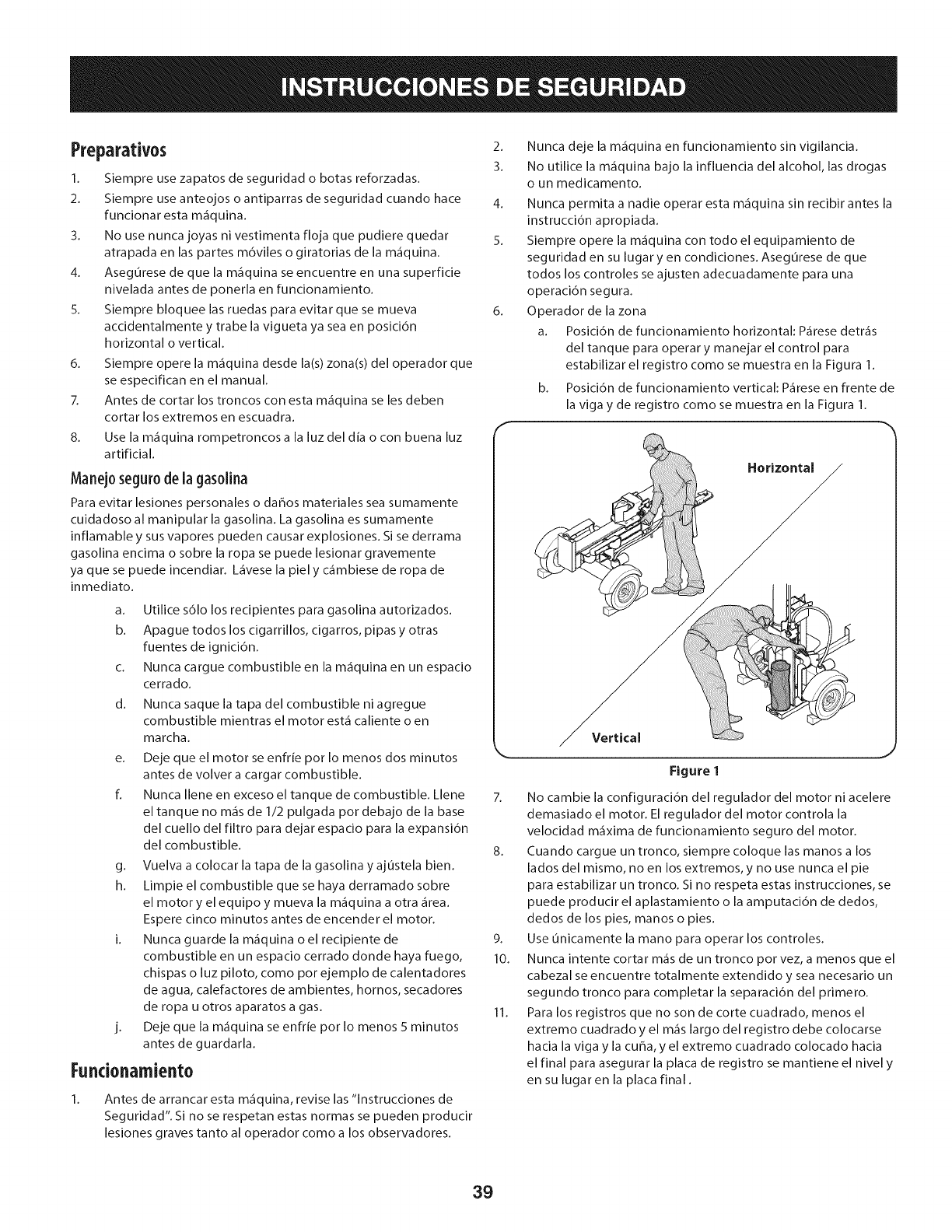
Preparativos
1. Siempre use zapatos de seguridad o botas reforzadas.
2. Siempre use anteojos o antiparras de seguridad cuando hace
funcionar esta m_quina.
3. No use nunca joyas ni vestimenta floja que pudiere quedar
atrapada en las partes m6viles o giratorias de la m_quina.
4. Asegurese de que la m_quina se encuentre en una superficie
nivelada antes de ponerla en funcionamiento.
5. Siempre bloquee las ruedas para evitar que se mueva
accidentalmente y trabe la vigueta ya sea en posici6n
horizontal o vertical.
6. Siempre opere la m_quina desde la(s) zona(s) del operador que
se especifican en el manual.
7. Antes de cortar los troncos con esta m_quina se les deben
cortar los extremos en escuadra.
8. Use la m_quina rompetroncosa la luzdel dia o con buena luz
artificial.
Manej0 segur0 de la gas01ina
Para evitar lesiones personales o da_os materiales sea sumamente
cuidadoso al manipular la gasolina. La gasolina es sumamente
inflamable y sus vapores pueden causar explosiones. Si se derrama
gasolina encima o sobre la ropa se puede lesionar gravemente
ya que se puede incendiar. L_vese la piel y c_mbiese de ropa de
inmediato.
a. Utilice s61o los recipientes para gasolina autorizados.
b. Apague todos los cigarrillos, cigarros, pipas y otras
fuentes de ignici6n.
c. Nunca cargue combustible en la m_quina en un espacio
cerrado.
d. Nunca saque la tapa del combustible ni agregue
combustible mientras el motor est_ caliente o en
marcha.
e. Deje que el motor se enfrie por Io menos dos minutos
antes de volver a cargar combustible.
f. Nunca Ilene en exceso el tanque de combustible. Llene
eltanque no m_s de 1/2 pulgada pot debajo de la base
del cuello del filtro para dejar espacio para la expansi6n
del combustible.
g. Vuelva a colocar la tapa de la gasolina y ajustela bien.
h. Limpie el combustible que se haya derramado sobre
el motor y el equipo y mueva la m_quina a otra _rea.
Espere cinco minutos antes de encender el motor.
i. Nunca guarde la m_quina o el recipiente de
combustible en un espacio cerrado donde haya fuego,
chispas o luz piloto, como pot ejemplo de calentadores
de agua, calefactores de ambientes, hornos, secadores
de ropa u otros aparatos a gas.
j. Deje que la m_quina se enfrie pot Io menos 5 minutos
antes de guardarla.
Fundonamiento
Antes de arrancar esta m_quina, revise las "lnstrucciones de
Seguridad". Si no se respetan estas normas se pueden producir
lesiones graves tanto al operador como a los observadores.
2. Nunca deje la m_quina en funcionamiento sin vigilancia.
3. No utilice la m_quina bajo la influencia del alcohol, las drogas
o un medicamento.
4. Nunca permita a nadie operar esta m_quina sin recibir antes la
instrucci6n apropiada.
5. Siempre opere la m_quina con todo el equipamiento de
seguridad en su lugar yen condiciones. Asegurese de que
todos los controles se ajusten adecuadamente para una
operaci6n segura.
6. Operador de la zona
a. Posici6n de funcionamiento horizontal: P_rese detr_s
del tanque para operar y manejar el control para
estabilizar el registro como se muestra en la Figura 1.
b. Posici6n de funcionamiento vertical: P_rese en frente de
la viga y de registro como se muestra en la Figura 1.
Horizontal
Vertical
Figure 1
J
7. No cambie la configuraci6n del regulador del motor ni acelere
demasiado el motor. El regulador del motor controla la
velocidad m_xima de funcionamiento seguro del motor.
8. Cuando cargue un tronco, siempre coloque las manos a los
lados del mismo, no en los extremos, y no use nunca el pie
para estabilizar un tronco. Si no respeta estas instrucciones, se
puede producir el aplastamiento o la amputaci6n de dedos,
dedos de los pies, manos o pies.
9. Use unicamente la mano para operar los controles.
10. Nunca intente cortar m_s de un tronco porvez, a menos que el
cabezal se encuentre totalmente extendido y sea necesario un
segundo tronco para completar la separaci6n del primero.
11. Para los registros que no son de corte cuadrado, menos el
extremo cuadrado y el m_s largo del registro debe colocarse
hacia la viga y la cuba, y el extremo cuadrado colocado hacia
el final para asegurar la placa de registro se mantiene el nivel y
en su lugar en la placa final.
39
12. Cuando corte en posici6n vertical, estabilice el tronco antes de
mover el control. Corte segun se indica a continuaci6n:
a. Coloque el tronco en la placa del extremo y girelo hasta
que se incline contra la vigueta y quede estable.
b. Cuando corte troncos muy grandes o desparejos, el
tronco se debe estabilizar con cu_as de madera o
madera cortada entre el tronco y la placa del extremo o
el suelo.
12. Mantenga los dedos alejados de cualquier hendidura
que se abra en el tronco mientras realiza el cortado. Estas
separaciones se pueden cerrar con rapidezy atrapar o amputar
dedos.
13. Mantenga limpia el _rea de trabajo. Retire inmediatamente la
madera cortada que quede alrededor de la m_quina para no
tropezarse con la misma.
14. Nunca mueva la m_quina mientras est_ en funcionamiento.
15. Esta m_quina no se debe remolcar en ninguna calle, ruta o
camino publico sin verificar los requisitos aplicables a los
vehiculos segun las reglamentaciones federales, estatales o
locales que se encuentren en vigencia. Cualquier autorizaci6n
o modificaci6n que se deba realizar, pot ejemplo, en relaci6n
con luces traseras, etc., es responsabilidad exclusiva del
comprador. Si en su estado se exige una "Declaraci6n de
Origen", consulte con su distribuidor local.
16. No remolque la m_quina pot encima de las 45 mph.
17. Vea la secci6n 'Transporte de la m_quina rompetroncos' de
este manual para consultar las instrucciones de remolque
adecuadas despu6s de haber cumplimentado todos los
requisitos federales, locales o estatales.
Mantenimiento y almacenamiento
Esta m_quina est_ equipada con un motor de combusti6n interna
y no debe ser utilizada en o cerca de un terreno agreste cubierto
pot bosque, malezas o hierba excepto si el sistema de escape del
motor est_ equipado con un amortiguador de chispas que cumpla
con las leyes locales o estatales correspondientes, en caso de
haberlas.
1. Detenga el motor, desconecte la bujia y haga masa contra el
motor antes de limpiar o inspeccionar la m_quina.
2. Detenga el motor y libere la presi6n del sistema hidr_ulico
antes de reparar o ajustar los accesorios, mangueras, tubos u
otros componentes del sistema.
3. Para evitar incendios, limpie la suciedad y grasa de las _reas
del motor y del silenciador. Si el motor est_ equipado con
un silenciador con amortiguador de chispas, limpielo e
inspecci6nelo regularmente segun las instrucciones de los
fabricantes. Reempl_celo si est_ daffado.
4. Peri6dicamente controle que todas las tuercas y pernos,
abrazaderas de mangueras y accesorios hidr_ulicos est6n
ajustados, para verificar que el equipo se encuentra en
condiciones de trabajo seguras.
5. Controle todos los protectores y escudos de seguridad para
verificar que se encuentren en posici6n adecuada. Nunca
opere la m_quina si se han retirado los protectores o escudos
de seguridad u otros dispositivos de protecci6n.
6. La v_lvula de descarga de presi6n viene preconfigurada de
f_brica. No la ajuste.
7. No intente nunca mover la m_quina en terreno en pendiente o
desparejo sin un vehiculo de remolque o sin ayuda adecuada.
8. Pot su seguridad, cambie todas las piezas dahadas o
desgastadas inmediatamente utilizando unicamente equipo
del fabricante original ('OEM'). La utilizaci6n de piezas que no
cumplen con las especificaciones de equipos originales puede
tenet como resultado un rendimiento inadecuado y puede
poner en riesgo la seguridad. Consult the Parts List in this
manual for correct replacement parts.
9. No modifique esta m_quina de ningun modo; si se realizan
modificaciones tales como agregado de una cuerda o
alargador a la manija de control, o el aumento del ancho o
la altura de la cuba, se pueden producir lesiones personales
graves.
10. Segun la Comisi6n de Seguridad de Productos para el
Consumidor de los Estados Unidos (CPSC) y la Agencia de
Protecci6n Ambiental de los Estados Unidos (EPA), este
producto tiene una vida util media de siete (7) ahos 6130
horas de funcionamiento. AI finalizar la vida util media,
adquiera una m_quina nueva o haga inspeccionar anualmente
esta unidad por un distribuidor de servicio autorizado
para cerciorarse de que todos los sistemas mec_nicos y de
seguridad funcionan correctamente y no tienen excesivo
desgaste. Si no Io hace, pueden producirse accidentes, lesiones
o la muerte.
Amortiguadordechispas
Si se utiliza un amortiguador de chispas el operador Io debe
mantener en condiciones de uso adecuadas. En el Estado de
California las medidas anteriormente mencionadas son exigidas pot
ley (Articulo 4442 del C6digo de Recursos Publicos de California).
Es posible que existan leyes similares en otros estados. Las leyes
federales se aplican en territorios federales.
Puede conseguir el amortiguador de chispas para el silenciador a
trav6s de su distribuidor de mantenimiento de motores autorizado
m_s cercano o poni6ndose en contacto con el departamento de
servicios.
4O
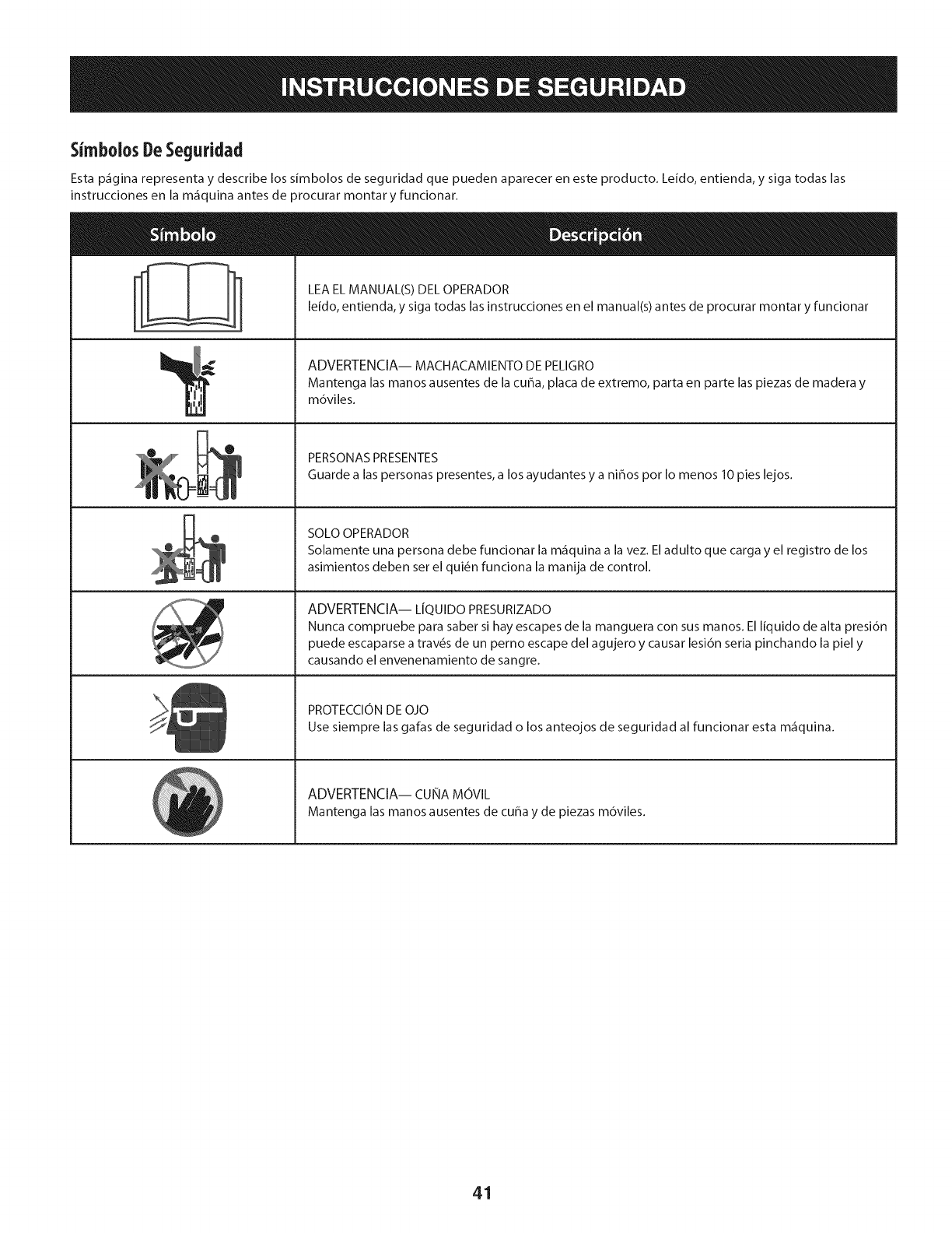
SimbolosDeSeguridad
Esta p_gina representa y describe los simbolos de seguridad que pueden aparecer en este producto. Leido, entienda, y siga todas las
instrucciones en la m_quina antes de _rocurar montary funcionar.
A
LEA EL MANUAL(S) DEL OPERADOR
leido, entienda, y siga todas las instrucciones en el manual(s) antes de procurar montar y funcionar
ADVERTENCIA-- MACHACAMIENTO DE PELIGRO
Mantenga las manos ausentes de la cuba, placa de extremo, parta en parte las piezas de madera y
m6viles.
PERSONAS PRESENTES
Guarde alas personas presentes, a los ayudantes y a ni_os pot Io menos 10 pies lejos.
SOLO OPERADOR
Solamente una persona debe funcionar la m_quina a la vez. Eladulto que carga y el registro de los
asimientos deben set el qui6n funciona la manija de control.
ADVERTENCIA-- LfQUIDO PRESURIZADO
Nunca compruebe para saber si hay escapes de la manguera con sus manos. El liquido de alta presi6n
puede escaparse a trav6s de un perno escape del agujero y causar lesi6n seria pinchando la piel y
causando el envenenamiento de sangre.
PROTECCION DE OJO
Use siempre las galas de seguridad o los anteojos de seguridad al funcionar esta m_quina.
ADVERTENCIA-- CUNA MOVlL
Mantenga las manos ausentes de cuba y de piezas m6viles.
41
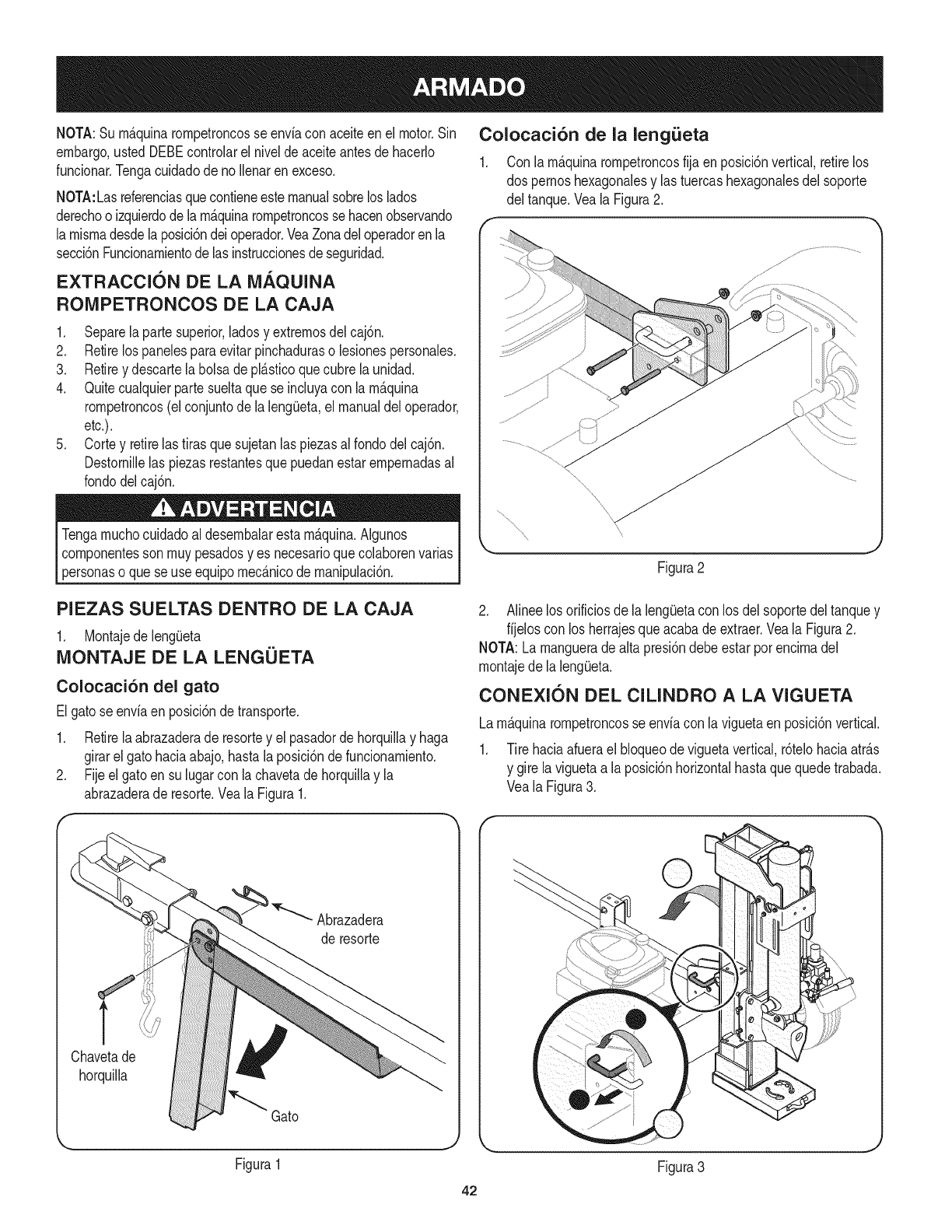
NOTA:Surn_.quinarornpetroncosse enviaconaceiteenel motor.Sin
embargo,ustedDEBEcontrolarel nivelde aceiteantesde hacerlo
funcionar.Tengacuidadode no Ilenarenexceso.
NOTA:Lasreferenciasquecontieneestemanualsobreloslados
derechoo izquierdode larn_.quinarornpetroncosse hacenobservando
larnisrnadesdelaposici6ndeioperador.VeaZonadeloperadorenla
secci6nFuncionarnientodelas instruccionesdeseguridad.
EXTRACCION DE LA MAQUINA
ROIVlPETRONCOS DE LA CAJA
1. Separelaparte superior,ladosy extrernosdel caj6n.
2. Retirelos panelesparaevitarpinchaduraso lesionespersonales.
3. Retirey descartelabolsa depl_.sticoquecubre launidad.
4. Quitecualquierpartesueltaque se incluyacon la rn_.quina
rornpetroncos(elconjuntodela lengOeta,el manualdel operador,
etc.).
5. Cortey retirelas tirasquesujetanlaspiezasal rondodel caj6n.
Destornillelas piezasrestantesquepuedanestarernpernadasal
rondodelcaj6n.
pTengarnuchocuidadoal desernbalaresta
rn_.quina.Algunos
cornponentesson rnuypesadosyes necesarioquecolaborenvarias
ersonaso quese useequipornec_.nicode rnanipulaci6n.
Colocaci6n de la leng_eta
1. Con la rn_.quinarornpetroncosfija en posici6nvertical,retirelos
dos pernoshexagonalesy las tuercashexagonalesdel soporte
del tanque.Veala Figura2.
Figura2
PIEZAS SUELTAS DENTRO DE LA CAJA
1. MontajedelengOeta
MONTAJE DE LA LENGUETA
Colocaci6n del gato
Elgato seenviaen posici6ndetransporte.
1. Retirela abrazaderade resortey el pasadordehorquillay haga
girarel gato haciaabajo,hastala posici6nde funcionarniento.
2. Fijeel gatoen su lugarconla chavetadehorquillay la
abrazaderade resorte.Veala Figura1.
2. Alineelosorificiosde lalengOetacon los delsoportedeltanquey
fijeloscon los herrajesqueacabadeextraer.Veala Figura2.
NOTA:La rnangueradealta presi6ndebeestarporencirnadel
rnontajede lalengOeta.
CONEXI(SN DEL CILINDRO A LA VIGUETA
Larn_.quinarornpetroncosse enviacon laviguetaen posici6nvertical.
1. Tire haciaafuerael bloqueodeviguetavertical,r6telohaciaatr_.s
y girelaviguetaa la posici6nhorizontalhastaquequedetrabada.
Veala Figura3.
Chavetade
horquilla
Abrazadera
de resorte
Gato
Figura1
J
42
Figura3

2. Desconecteelliberadordelsoportesoldadodeviguetaretirando
losseistornilloshexagonales.VealaFigura4. 4. Levanteydesliceelcilindrohaciaarribahastaeltopedela
viguetaydentrodelossoportessoldados.VealaFigura6.
Figura4
Desconectelarn_nsuladelbastidordetroncosdelladodela
v_.lvuladecontroldelavigueta.VealaFigura5.
Figura5
.
Figura6
5. Coloqueel liberadorencirnadelrnontajedela cubay fijeloen los
soportessoldadoscon los herrajesextraidospreviarnente.Veala
Figura6.
NOTA:Unavezapretadoslos seistornilloshexagonales,puedehaber
unapeque_aseparaci6nentreelliberadory los soportessoldados.
Estaseparaci6nes normal.
6. Vuelvaa colocarel bastidordetroncosalcostadode lavigueta
con la v_.lvuladecontrol,alineandolosextrernosdelbastidorcon
lasbridasde lavigueta.
7. Hagarodarla rn_.quinarornpetroncosfuerade la parteinferiorde
lacaja.
CONFIGURACION
Llenado de gasolina y aceite
Cargueelmotorcongasolinay aceitecornose indicaacontinuaci6n.
Lealas instruccionescon atenci6n.
Tengarnuchocuidadoaltrabajarcongasolina.Lagasolinaes
sumarnenteinfiarnabley susvaporespuedencausarexplosiones.
Nuncaagreguecombustibleala rn_.quinaen interioreso rnientrasel
motorest,.calienteo enfuncionarniento.
NOTA:Surn_.quinarornpetroncosse envfacon aceiteenel motor.
UstedDEBEcontrolarel niveldeaceiteantesde hacerfuncionarla
rn_.quina.Tengacuidadode noIlenaren exceso.Se puedeagregar
gasolinaal motorcuandola rn_.quinarornpetroncosseencuentraen
posici6nhorizontalo vertical.Sinembargo,hay rnenosobstrucciones
cuandola unidadse encuentraenposici6nvertical.
Aceite
1. Saquelavarilladelnivelde aceite.
2. Cornpruebeelniveldeaceiteasegur_.ndosequelavarilladelnivel
deaceitenoroceconlasparedesinterioresdeltubodeIlenadode
aceite.Dehacerlose puedeproducirunalecturafalsadelavarilla
delniveldeaceite.LlenehastalarnarcaFULL(lleno)delavarilladel
niveldeaceite,si esnecesario.Vuelvaacolocarlavarillay ajuste.
43
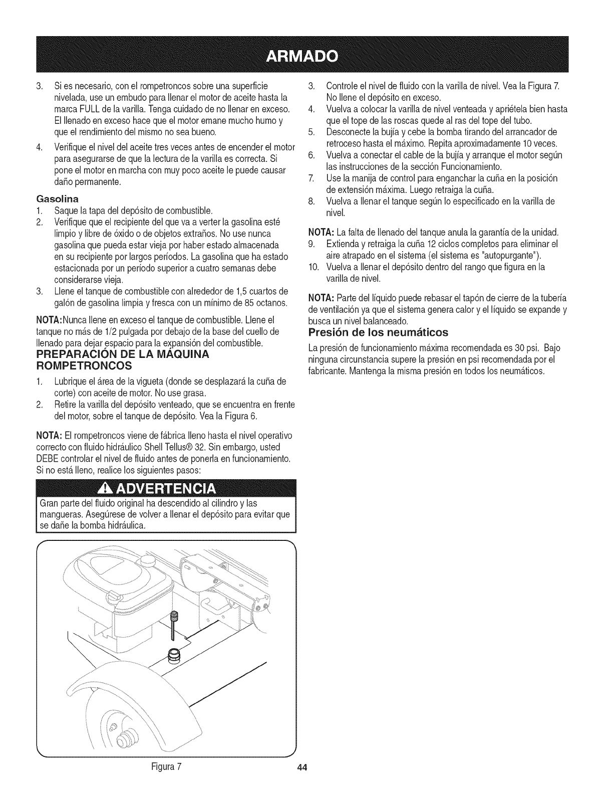
3. Sies necesario,conel rornpetroncossobreunasuperficie
nivelada,use unernbudoparaIlenarelmotordeaceitehastala
rnarcaFULLde lavarilla.Tengacuidadode noIlenaren exceso.
El Ilenadoen excesohacequeel motorernanernuchohurnoy
queel rendirnientodel rnisrnonosea bueno.
4. Verifiqueel niveldelaceitetresvecesantesde encenderel motor
paraasegurarsede quela lecturadela varillaes correcta.Si
poneel motoren rnarchacon rnuypoco aceitele puedecausar
da_operrnanente.
Gasolina
1. Saquela tapadeldep6sitodecombustible.
2. Verifiquequeel recipientedel queva averterlagasolinaest_
lirnpioy librede 6xidoo de objetosextraSos.No usenunca
gasolinaquepuedaestarviejapor haberestadoalrnacenada
en su recipientepor largosperiodos.Lagasolinaquehaestado
estacionadaporun periodosuperiora cuatrosernanasdebe
considerarsevieja.
3. Lleneel tanquedecombustibleconalrededorde 1,5cuartosde
gal6nde gasolinalirnpiay frescacon un rninirnode 85octanos.
NOTA:NuncaIleneen excesoeltanquede combustible.Lleneel
tanquenorn_.sde 1/2 pulgadapordebajode la basedelcuellode
Ilenadoparadejarespacioparalaexpansi6ndel combustible.
PREPARACION DE LA IViAQUINA
ROIViPETRONCOS
1. Lubriqueel Areadela vigueta(dondese desplazar_,la cubade
corte)conaceitede motor.Nousegrasa.
2. Retirela varilladel dep6sitoventeado,queseencuentraenfrente
delmotor,sobreel tanquede dep6sito.VealaFigura6.
3. Controleel niveldefluidocon lavarillade nivel.Veala Figura7.
NoIleneeldep6sitoen exceso.
4. Vuelvaa colocarlavarilladenivelventeaday apri_telabienhasta
queel topede las roscasquedeal rasdeltope deltubo.
5. Desconectelabujiay cebe la bornbatirandodelarrancadorde
retrocesohastael rn_.xirno.Repitaaproxirnadarnente10veces.
6. Vuelvaa conectarel cablede la bujiay arranqueel motorsegQn
las instruccionesde lasecci6nFuncionarniento.
7. Usela rnanijadecontrolparaengancharlacubaen la posici6n
de extensi6nrn_.xirna.Luegoretraigalacuba.
8. Vuelvaa IlenareltanquesegQnIoespecificadoen lavarillade
nivel.
NOTA: Lafaltade Ilenadodel tanqueanulalagaranfiade launidad.
9. Extienday retraigala cuSa12cicloscornpletosparaelirninarel
aireatrapadoen elsisterna(el sisternaes "autopurgante").
10. Vuelvaa Ilenareldep6sitodentrodelrangoque figuraenla
varillade nivel.
NOTA: Partedel liquidopuederebasarel tap6ndecierrede latuberia
de ventilaci6nya queel sisternageneracalory el liquidose expandey
buscaunnivelbalanceado.
Presi6n de los neumaticos
Lapresi6nde funcionarnientomaximarecornendadaes 30 psi. Bajo
ningunacircunstanciasuperelapresi6nen psi recornendadaporel
fabricante.Mantengala rnisrnapresi6nentodoslos neurn_.ticos.
NOTA: Elrornpetroncosviene def_.bricaIlenohastael niveloperativo
correctocon fiuidohidr_.ulicoShellTellus®32. Sinembargo,usted
DEBEcontrolarel niveldefluidoantesdeponerlaenfuncionarniento.
Si noest,.Ileno,realicelossiguientespasos:
Granpartedel fluidooriginalhadescendidoal cilindroy las
rnangueras.AsegQresedevolvera Ilenareldep6sitoparaevitarque
sedaSela bornbahidr_.ulica.
i
\\
Figura7 44
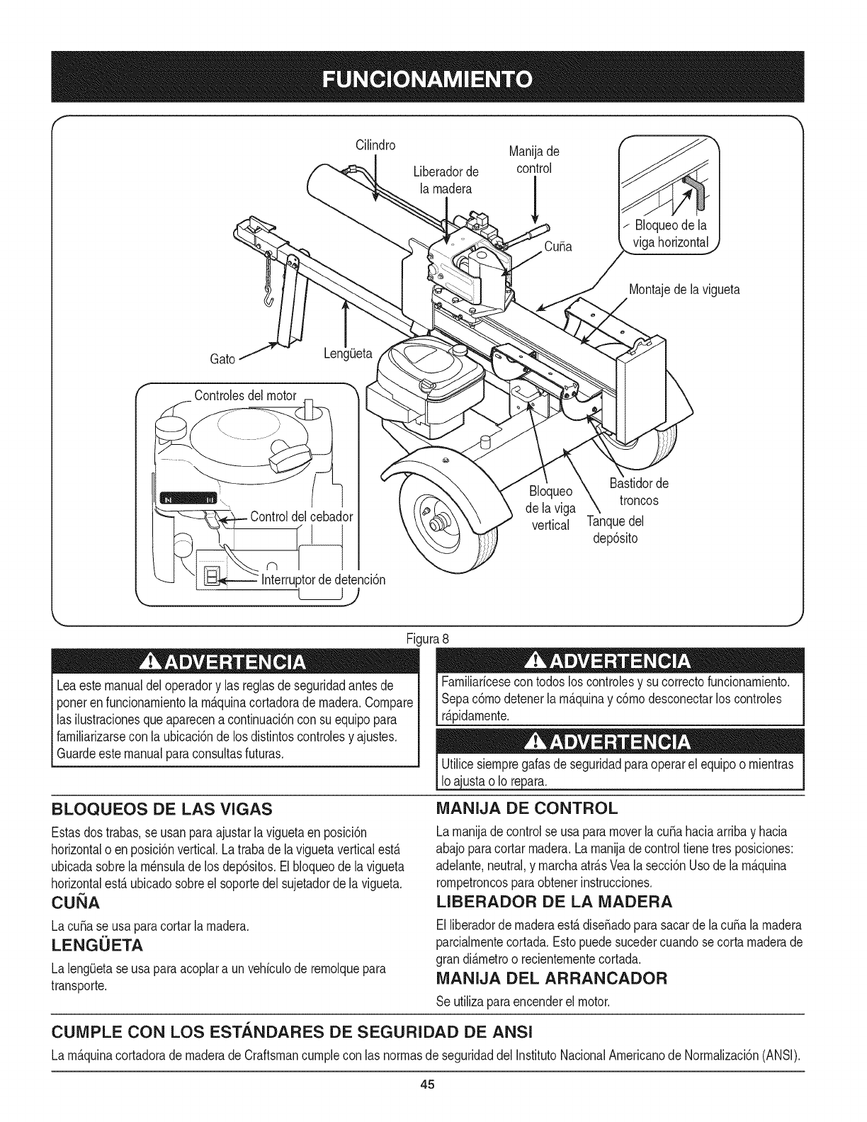
Cilindro Manijade
Liberadorde control
larnadera
Cuba
Bloqueode la
viga horizontal
Montajede lavigueta
Gato
rControlesdel motor
Controldelcebado_
Interruptorde detencidn
Bloqueo
de la viga
vertical
de
troncos
Tanquedel
dep6sito
Fi,
Leaestemanualdeloperadory las reglasdeseguridadantesde
ponerenfuncionarnientola rn_.quinacortadorade rnadera.Compare
las ihstracionesqueaparecenacontinuaci6ncon su equipopara
farniliarizarsecon la ubicaci6nde los distintoscontrolesy ajustes.
Guardeestemanualparaconsultasfuturas.
BLOQUEOS DE LAS VIGAS
Estasdostrabas,se usanparaajustarlaviguetaen posici6n
horizontalo enposici6nvertical.Latrabade la viguetaverticalest,.
ubicadasobrela rn_nsulade los dep6sitos.Elbloqueode lavigueta
horizontalest,.ubicadosobreel soportedelsujetadorde la vigueta.
CUK A
LacuSase usaparacortarlarnadera.
LENGUETA
La leng_Jetaseusa paraacoplara unvehiculode rernolquepara
transporte.
ura8
Farniliaricesecon todosloscontrolesy sucorrectofuncionarniento.
Sepac6rnodetenerlarn_.quinay c6rnodesconectarloscontroles
r_.pidarnente.
ustao Io repar&
iVlANIJA DE CONTROL
Larnanijade controlse usa paramoverlacubahaciaarribay hacia
abajoparacortarrnadera.La rnanijadecontroltiene tresposiciones:
adelante,neutral,y rnarchaatr_.sVealasecci6nUsodela rn_.quina
rornpetroncosparaobtenerinstrucciones.
LIBERADOR DE LA iVlADERA
Elliberadorde rnaderaest,.dise_adoparasacarde lacuba larnadera
parcialrnentecortada.Estopuedesucedercuandosecorta rnaderade
grandi_.rnetroo recienternentecortada.
iVlANIJA DEL ARRANCADOR
Se utilizaparaencenderel motor.
CUiVIPLE CON LOS ESTANDARES DE SEGURIDAD DE ANSI
La rn_.quinacortadorade rnaderadeCraftsmancurnplecon las norrnasde seguridaddel InstitutoNacionalArnericanode Norrnalizaci6n(ANSI).
45
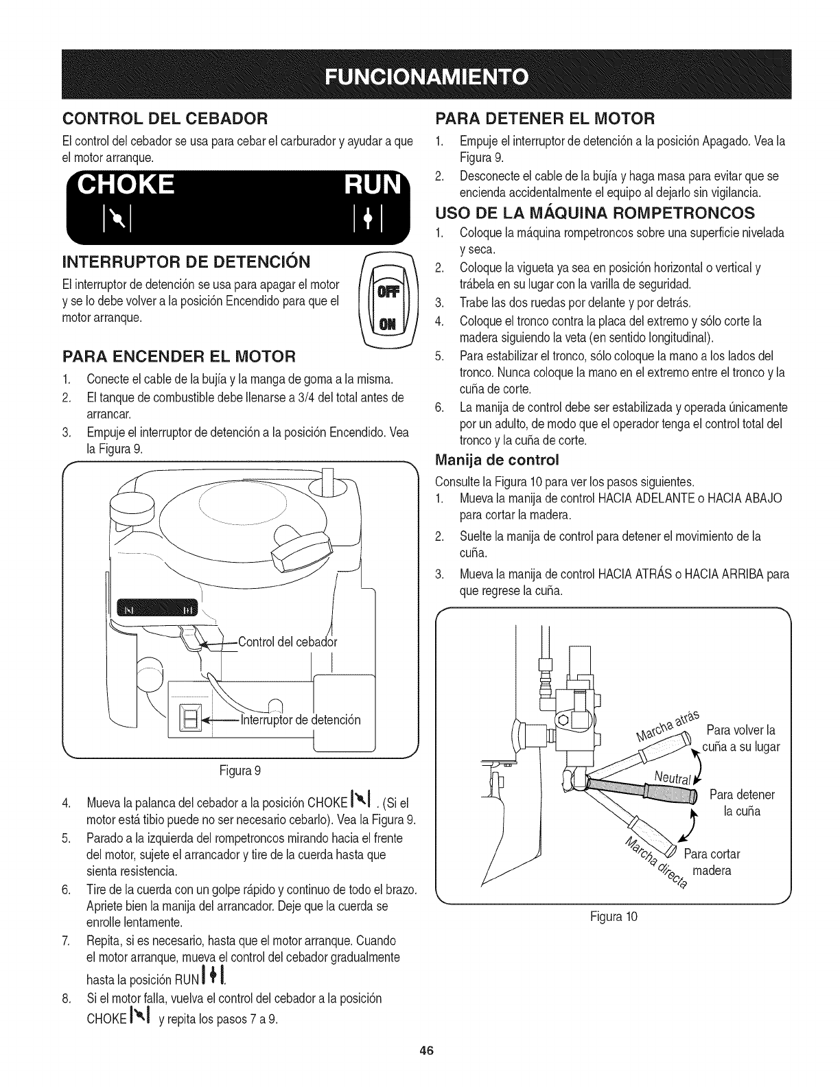
CONTROL DEL CEBADOR
Elcontroldel cebadorse usa paracebarel carburadory ayudara que
el motorarranque.
INTERRUPTOR DE DETENCION
Elinterruptorde detenci6nse usaparaapagarel motor
y se Io debevolvera laposici6nEncendidoparaqueel
motorarranque.
PARA ENCENDER EL MOTOR
1. Conecteel cabledela bujfay larnangadegornaa la rnisrna.
2. EltanquedecombustibledebeIlenarsea 3/4 del totalantesde
arrancar.
3. Ernpujeel interruptorde detenci6na la posici6nEncendido.Vea
la Figura9.
f
L,,
delcebador
Interruptordedetenci6n
t
Figura 9
4. Muevalapalancadelcebadora laposici6nCHOKE I",I.(siel
motorest,.tibio puedenoser necesariocebarlo).Yeala Figura9.
5. Paradoa laizquierdadelrornpetroncosrnirandohaciael frente
delmotor,sujeteel arrancadory tire dela cuerdahastaque
sientaresistencia.
6. Tirede lacuerdacon ungolper_.pidoy continuode todoel brazo.
Aprietebienla rnanijadel arrancador.Dejequela cuerdase
enrollelentarnente.
7. Repita,si es necesario,hastaqueelmotorarranque.Cuando
el motorarranque,rnuevael controldelcebadorgradualrnente
hastala posici6nRUNI _ !.
8. Siel motorfalla,vuelvael controldelcebadora laposici6n
CHOKEI'_1 y repitalos pasos7 a9.
PARA DETENER EL MOTOR
1. Ernpujeelinterruptordedetenci6na laposici6nApagado.Veala
Figura9.
2. Desconecteel cablede la bujiay hagarnasaparaevitarquese
enciendaaccidentalrnenteel equipoaldejarlosinvigilancia.
USO DE LA M.&.QUINA ROMPETRONCOS
1. Coloquelarn&quinarornpetroncossobreunasuperficienivelada
y seca.
2. Coloquelaviguetaya sea enposici6nhorizontalo verticaly
tr_.belaen sulugarcon lavarillade seguridad.
3. Trabelasdos ruedaspot delantey pordetr_.s.
4. Coloqueel troncocontrala placadelextrernoy s61ocortela
rnaderasiguiendola veta(ensentidolongitudinal).
5. Paraestabilizarel tronco,s61ocoloquelarnanoa los ladosdel
tronco.Nuncacoloquelarnanoenel extrernoentreel troncoy la
cuSade corte.
6. Larnanijade controldebeserestabilizaday operadaOnicarnente
porunadulto,dernodoqueel operadortengael controltotaldel
troncoy la cuSadecorte.
IVlanija de control
Consultela Figura10paraver los pasossiguientes.
1. Muevala rnanijade controlHACIAADELANTEo HACIAABAJO
paracortarla rnadera.
2. Sueltela rnanijade controlparadetenerel rnovirnientodela
cuba.
3. Muevala rnanijade controlHACIAATRASo HACIAARRIBApara
que regreselacuSa.
Paravolverla
cuSaa su lugar
Paradetener
lacuba
Paracortar
_,_ee/rnadera
Figura10
46
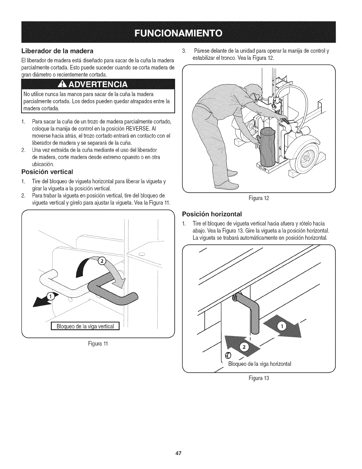
Liberador de la madera
El liberadordernaderaest,.dise_adoparasacarde la cubala rnadera
parcialmentecortada.Estopuedesucedercuandose cortamaderade
grandi_.metroo recientementecortada.
NoutiNcenuncalas manosparasacardela cubala madera
parcialmentecortada.Losdedospuedenquedaratrapadosentrela
maderacortada.
3. P_.resedelantede la unidadparaoperarlamanijadecontroly
estabilizareltronco.Veala Figura12.
1. Parasacarlacuba deun trozode rnaderaparcialmentecortado,
coloquela manijade controlen la posici6nREVERSE.AI
moversehaciaatr_.s,el trozocortadoentrar_,encontactocon el
liberadorde maderay se separar_,de lacuba.
2. Unavezextrafdade lacuba medianteel usodel Nberador
de madera,cortemaderadesdeextremoopuestoo enotra
ubicaci6n.
Posici6n vertical
1. Tiredel bloqueode viguetahorizontalparaliberarlaviguetay
girarlaviguetaa la posici6nvertical.
2. Paratrabarla viguetaenposici6nvertical,tire delbloqueode
viguetaverticaly gfreloparaajustarla vigueta.Veala Figura11.
...................:
Figura11
Figura12
Posici6n horizontal
1. Tire el bloqueode viguetaverticalhaciaafueray r6telohacia
abajo.Veala Figura13.Girela viguetaa laposici6nhorizontal.
Laviguetase trabar_,autom_.ticamenteenposici6nhorizontal.
Bloqueode laviga horizontal
Figura13
47
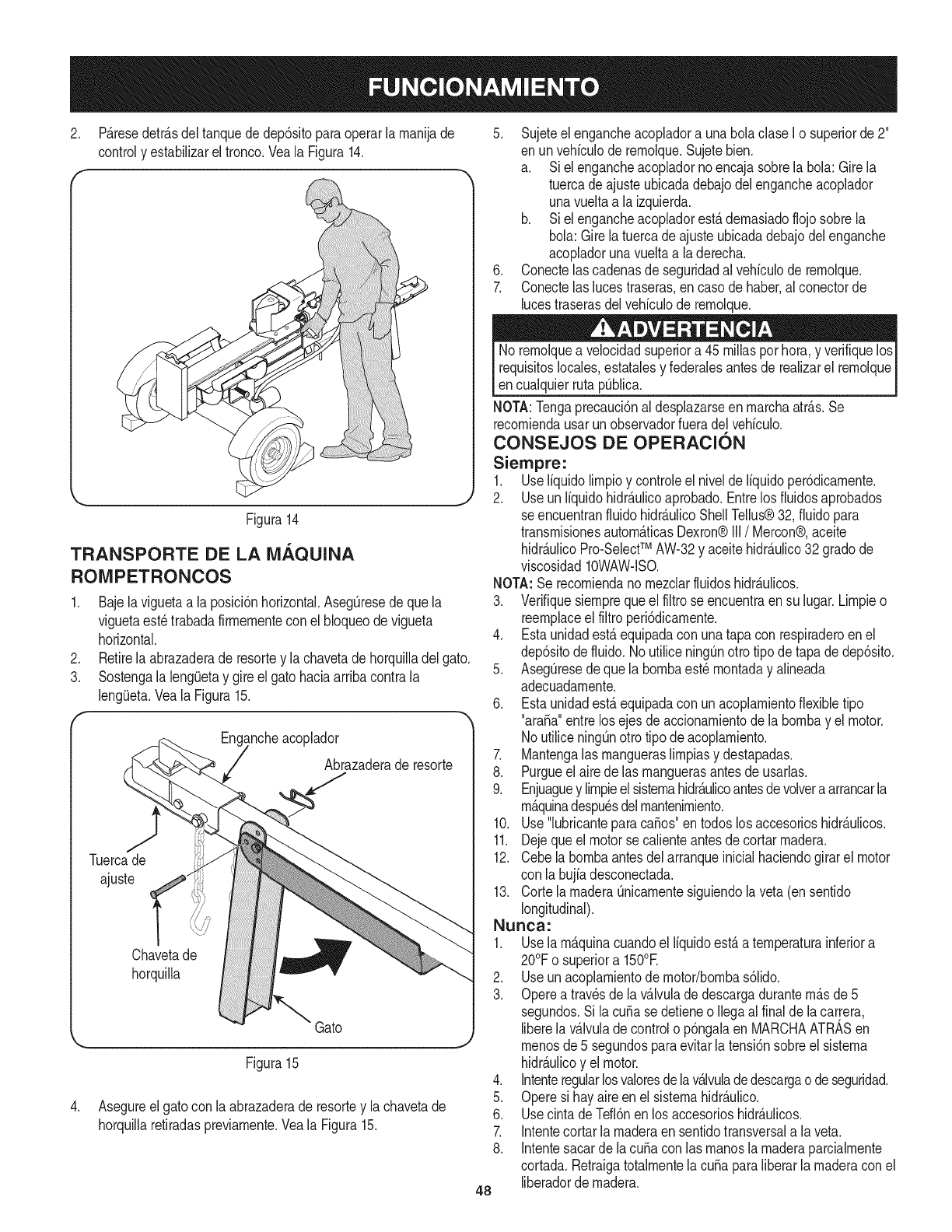
.P_.resedetr_.sdel tanquede dep6sitoparaoperarla rnanijade
controly estabilizareltronco.Veala Figura14.
5. Sujeteelengancheacopladora unabolaclaseI o superiorde 2"
en unvehiculode rernolque.Sujetebien.
a. Siel engancheacopladornoencajasobrela bola: Girela
tuercadeajusteubicadadebajodelengancheacoplador
unavueltaa laizquierda.
b. Siel engancheacopladorest,.dernasiadoflojosobrela
bola:Girelatuercadeajusteubicadadebajodelenganche
acopladorunavueltaa la derecha.
6. Conectelascadenasde seguridadal vehiculode rernolque.
7. Conectelaslucestraseras,en casodehaber,al conectorde
lucestraserasdelvehiculode rernolque.
Figura14
TRANSPORTE DE LA iVlAQUINA
ROIVIPETRONCOS
1. Bajelaviguetaa la posici6nhorizontal.Aseg0resedequela
viguetaestetrabadafirrnernentecon el bloqueodevigueta
horizontal.
2. Retirela abrazaderade resortey la chavetadehorquilladel gato.
3. Sostengala lengQetaygireel gatohaciaarribacontrala
leng(Jeta.Veala Figura15.
Eng_!ncheacoplador
Abrazaderade resorte
Tuercade
ajuste
Chavetade
horquilla
Gato
Figura15
4. Asegureelgato conla abrazaderade resortey lachavetade
horquillaretiradaspreviarnente.Veala Figura15.
No rernolquea velocidadsuperiora 45rnillasporhora,y verifiquelos
requisitoslocales,estatalesy federalesantesde realizarel rernolque
encualquierrutap0blica.
NOTA:Tengaprecauci6naldesplazarseenrnarchaatr_.s.Se
recorniendausarun observadorfueradel vehiculo.
CONSEJOS DE OPERACION
Siempre:
1. Useliquidolirnpioy controleel niveldeliquidoper6dicarnente.
2. Useun liquidohidr_.ulicoaprobado.Entrelos fluidosaprobados
seencuentranfluidohidr_tulicoShellTellus®32, fluidopara
transrnisionesautorn_.ticasDexron®III/Mercon®,aceite
hidr_.ulicoPro-SelectTM AW-32y aceitehidr_.ulico32 gradode
viscosidad10WAW-ISO.
NOTA:Serecorniendanornezclarfluidoshidr_.ulicos.
3. Verifiquesiernprequeel filtrose encuentraen su lugar.Lirnpieo
reernplaceel filtroperi6dicarnente.
4. Estaunidadest,.equipadacon unatapa con respiraderoen el
dep6sitodefluido.No utiliceningQnotto tipode tapade dep6sito.
5. AsegQresedeque la bornbaest_rnontaday alineada
adecuadarnente.
6. Estaunidadest,.equipadacon un acoplarnientoflexibletipo
"araSa"entrelos ejesde accionarnientodela bornbay el motor.
NoutiliceningOnottotipo deacoplarniento.
7. Mantengalas rnangueraslirnpiasy destapadas.
8. Purgueel airedelas rnanguerasantesde usarlas.
9. Enjuaguey lirnpieelsisternahidr_.ulicoantesdevolvera arrancarla
rn_.quinadespu_sdelrnantenirniento.
10. Use"lubricanteparacaSos"en todoslosaccesorioshidr_.ulicos.
11. Dejequeelmotorse calienteantesdecortarrnadera.
12. Cebelabornbaantesdelarranqueinicialhaciendogirarel motor
con la bujfadesconectada.
13. Cortela rnaderaQnicarnentesiguiendolaveta(en sentido
longitudinal).
Nunca:
1. Usela rn_.quinacuandoel liquidoest,.a ternperaturainferiora
20°Fo superiora 150°E
2. Useun acoplarnientode motor/bornbas61ido.
3. Opereatravesdela v_.lvuladedescargadurantern_.sde5
segundos.Si lacuSasedetieneo Ilegaal finalde la carrera,
liberela v_.lvulade controlo p6ngalaen MARCHAATRASen
rnenosde 5 segundosparaevitarla tensi6nsobreelsisterna
hidr_.ulicoy el motor.
4. Intenteregularlosvaloresdelav_.lvuladedescargao deseguridad.
5. Operesi hayaireen el sisternahidr_.ulico.
6. UsecintadeTefl6nen losaccesorioshidr_.ulicos.
7. Intentecortarla rnaderaen sentidotransversala la veta.
8. Intentesacarde lacuSaconlas rnanosla rnaderaparcialrnente
cortada.Retraigatotalrnentela cuSaparaliberarla rnaderacon el
liberadordernadera.
48
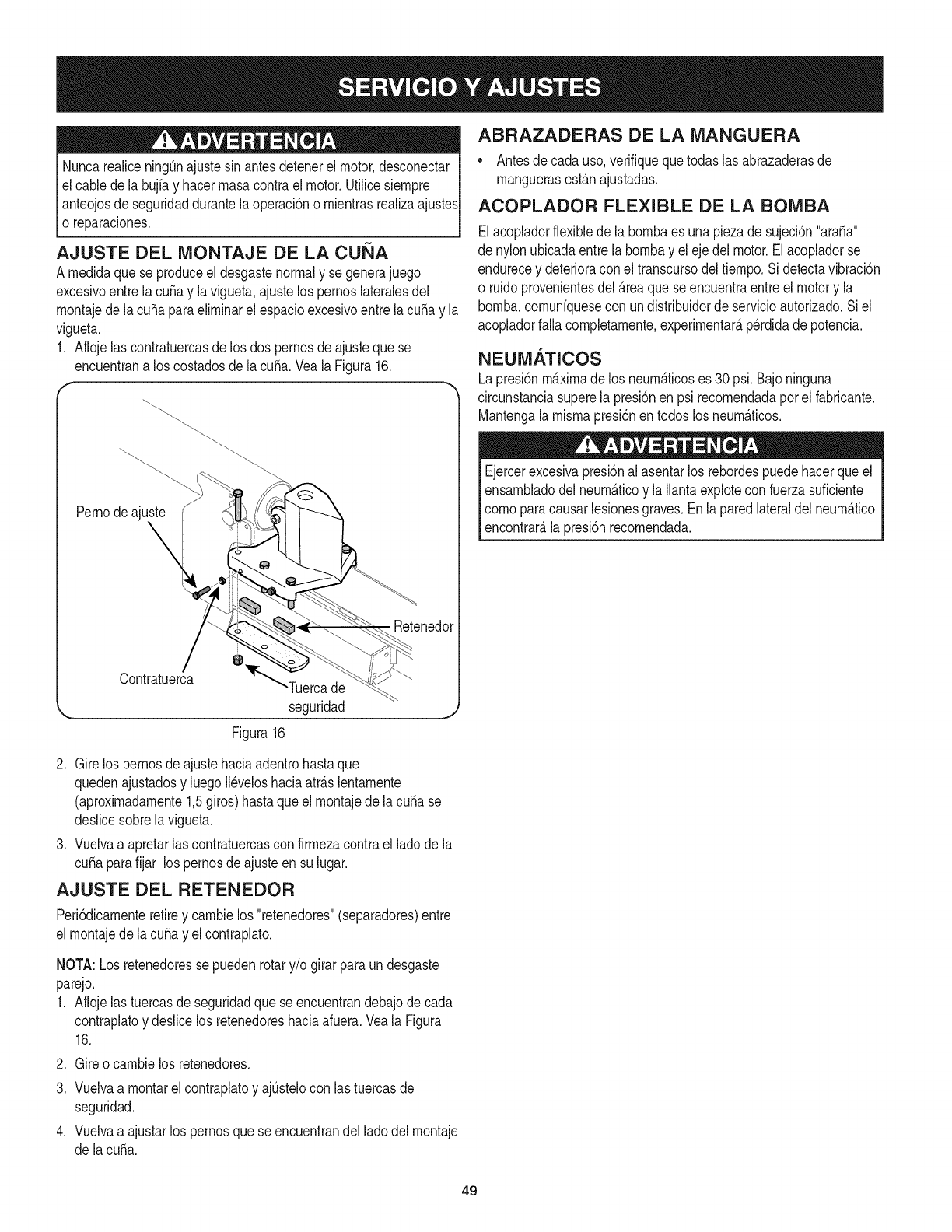
Nuncarealicening[3najustesin antesdetenerel motor,desconectar
elcable dela bujiay hacerrnasacontrael motor.Utilicesiernpre
I anteojosde seguridaddurantelaoperaci6no rnientrasrealizaajustesI
o reparaciones, j
AJUSTE DEL MONTAJE DE LA CUi_A
A rnedidaquese produceel desgastenormaly se generajuego
excesivoentrela cuSay la vigueta,ajustelos pernoslateralesdel
rnontajede la cuSaparaelirninarel espacioexcesivoentre lacuSay la
vigueta.
1. Aflojelas contratuercasde losdos pernosdeajustequese
encuentrana los costadosdela cuSa.Veala Figura16.
Pernodeajuste
\
Retenedol
Contratuerca "Tuercade
seguridad
Figura16
J
2. Girelos pernosde ajustehaciaadentrohastaque
quedenajustadosy luegoII_veloshaciaatr_.slentarnente
(aproxirnadarnente1,5giros)hastaqueel rnontajede lacuba se
deslicesobrela vigueta.
3. Vuelvaa apretarlas contratuercascon firrnezacontraelladode la
cubaparafijar los pernosdeajusteensu lugar.
AJUSTE DEL RETENEDOR
Peri6dicarnenteretirey carnbielos "retenedores"(separadores)entre
el rnontajede lacuba yel contraplato.
NOTA:Losretenedoressepuedenrotary/o girarparaundesgaste
parejo.
1. Aflojelas tuercasde seguridadquese encuentrandebajodecada
contraplatoy deslicelos retenedoreshaciaafuera.Veala Figura
16.
.
3.
.
Gireocarnbielos retenedores.
Vuelvaa rnontarelcontraplatoy ajQstelocon lastuercasde
seguridad.
Vuelvaa ajustarlos pernosquese encuentrandel ladodel rnontaje
de lacuba.
ABRAZADERAS DE LA MANGUERA
• Antesde cadauso,verifiquequetodaslasabrazaderasde
rnanguerasest_.najustadas.
ACOPLADOR FLEXIBLE DE LA BOIVIBA
Elacopladorflexiblede labornbaes unapiezade sujeci6n"ara_a"
denylonubicadaentrela bornbayel ejedel motor.Elacopladorse
endurecey deterioraconel transcursodeltiernpo.Si detectavibraci6n
o ruidoprovenientesdel_.reaquese encuentraentreel motory la
bornba,cornuniquesecon undistribuidorde servicioautorizado.Siel
acopladorfalla cornpletarnente,experirnentar_,perdidade potencia.
NEUMATICOS
Lapresi6nm_.xirnade los neurn_.ticoses 30 psi.Bajoninguna
circunstanciasuperela presi6nen psi recornendadaporelfabricante.
Mantengala rnisrnapresi6nen todoslosneurn_.ticos.
Ejercerexcesivapresi6nal asentarlos rebordespuedehacerqueel
ensarnbladodelneurn_.ticoy la Ilantaexplotecon fuerzasuficiente
cornoparacausarlesionesgraves.Enlaparedlateraldel neurn_.tico
encontrar_,la presi6nrecornendada.
49
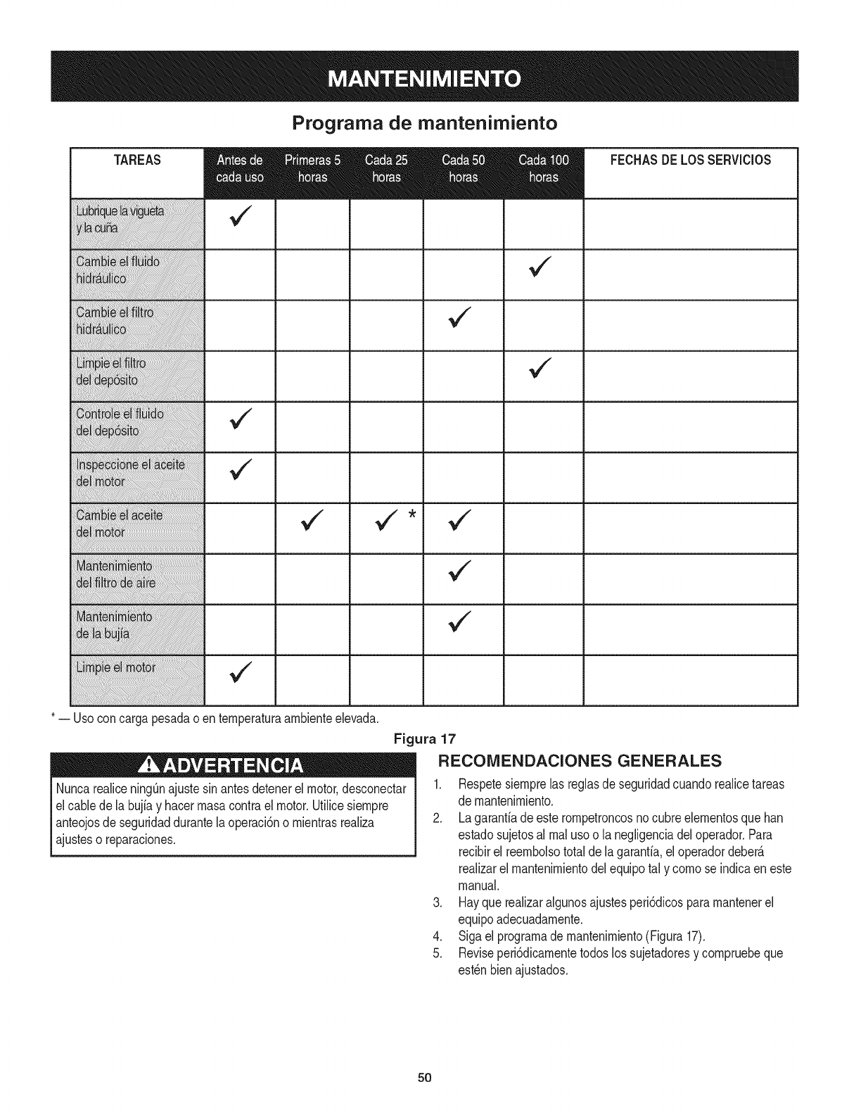
Programa de mantenimiento
¢"
TAREAS
* -- Usoconcarga pesadao enternperaturaarnbienteelevada.
Nuncarealicening[3najustesinantesdetenerel motor,desconectar
el cablede la bujiay hacerrnasacontrael motor.Utilicesiernpre
anteojosdeseguridaddurantela operaci6no rnientrasrealiza
ajusteso reparaciones.
FECHASDELOSSERVlCIOS
Figura 17
RECOMENDACIONES GENERALES
1. Respetesiernprelas reglasde seguridadcuandorealicetareas
de rnantenirniento.
2. Lagaranfiade esterornpetroncosnocubreelernentosqueban
estadosujetosal rnalusoo lanegligenciadel operador.Para
recibirel reernbolsototaldela garanfia,eloperadordeber_.
realizarel rnantenirnientodelequipotal y cornose indicaeneste
manual.
3. Hayque realizaralgunosajustesperi6dicospararnantenerel
equipoadecuadarnente.
4. Sigael prograrnade rnantenirniento(Figura 17).
5. Reviseperi6dicarnentetodoslos sujetadoresy cornpruebeque
est_nbienajustados.
50
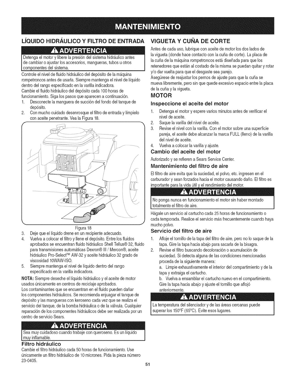
LJQUIDO HIDRAULICO YFILTRO DE ENTRADA VIGUETA Y CUi_IA DE CORTE
del sistema,
Controleel nivelde fluidohidr&ulicodel dep6sitode la m_.quina
rompetroncosantesde usarla,Siempremantengael nivelde liquido
dentrodelrangoespedficadoen lavarillaindicadora.
Cambieelfluido hidr_.ulicodeldep6sitocada 100horasde
funcionamiento,Sigalos pasosqueaparecena confinuaci6n,
1, Desconectela manguerade succbn delfondodel tanquede
dep6sito,
2, Conmuchocuidadodesenrosqueel filtrode entraday limpielo
conaceitepenetrante.Veala Figura18.
Figura18
3. Dejequeel liquidodreneen un recipienteadecuado.
4. Vuelvaa colocarel filtroy Ileneeldep6sito.Entrelos fluidos
aprobadosse encuentranfluidohidr_.ulicoShellTellus®32, fluido
paratransmisionesautom_.ticasDexron®III/Mercon®,aceite
hidr_.ulicoPro-SelectTM AW-32y aceitehidr_.ulico32 gradode
viscosidad10WAW-lSO.
5. Siempremantengael niveldeliquidodentrodel tango
especificadoen la varillaindicadora.
NOTA:Siempredesecheel liquidohidr_.ulicoy el aceitede motor
usadosOnicamenteencentrosde reciclajeaprobados.
Loscontaminantesquese encuentranenel fluidopuedenda_ar
los componenteshidr_.ulicos.Se recomiendaenjuagarel tanquede
dep6sitoy las manguerascon kerosenocadavezquese realizael
serviciodel tanque,dela bombahidr_.ulicao de lav_Jvula.Cualquier
reparaci6nde loscomponenteshidr_.ulicosdebeser realizadaporun
centrode servicioSears.
Seamuycuidadosocuandotrabajecon queroseno.Es unliquido I
nf amabe. [
Filtro hidraulico
Cambieelfiltrohidr_.ulicocada50 horasde funcionamiento.Use
0nicamenteunfiltrohidr_.ulicode 10micrones.Pidalapiezan0mero
23-0405. 51
Antesdecada uso,lubriquecon aceitede motorlosdos [adosde
lavigueta(dondehacecontactocon lacuffade corte). Laplacade
[acuffade [a m_.quinarompetroncosest,.diseffadaparaquelos
retenedoresqueest_.na[ costadode la mismase puedanquitary rotar
y/o darvueltaparaqueel desgastesea parejo.
AsegQresede reajustarlos pernosde ajusteparaquelacuffa se
muevalibremente,perosin quequedeexcesivoespacioentre[a piaca
de lacuffa y la vigueta.
MOTOR
Inspeccione el aceite del motor
1. Detengael motory esperevariosminutosantesde verificarel
niveldeaceite.
2. Saquelavariiiadelnivelde aceite.
3. Reviseel nivelcon[a varilla.Cone[ motorsobreunasuperficie
pareja,el aceitedebeaicanzar[a marcaFULL(lieno)de [avariiia
de[ nive[deaceite.
4. Vuelvaa colocarlavarillay ajuste.
Cambio del aceite del motor
Autorizadoy se refierena SearsServiceCenter.
Mantenimiento del filtro de aire
EIfiitrodeaireevitaque[a suciedad,e[ poivo,etc. ingresenen e[
carburadory seanforzadoshaciael motorcausandodaffo. Elfiltroes
v
Noponganuncaen funcionamientoel motorsin habermontado
totaimenteelfiitrode aire.
H_.galeunservicioal cartuchocada25 horasdefuncionamientoo
cadatemporada.Reaiiceel serviciom_.sfrecuentementecuandohaya
muchopolvo.
Servicio del filtro de aire
.
2.
Aflojeel tornillode la tapadelfiltrode aire,peronoIo saquedela
tapa.Girela tapahaciaabajoparasacarlade la bisagra.
Reviseelfiltro buscandodecoloraci6no acumulaci6nde
suciedad.Si detectaalgunade lascondicionesmencionadas
procedade la siguientemanera:
a. Limpieexhaustivamenteel interiordelcompartimientoy dela
tapa y extraigael cartucho.
b. Vuelvaa ensamblarelcartuchonuevoen elcompartimiento.
Girela tapahaciaabajoy ajusteel tornilloqueafloj6
anteriormente.
Latemperaturadel silenciadory de las_.reascercanaspuede
superarlos 150°F(65°0). Eviteesoslugares.
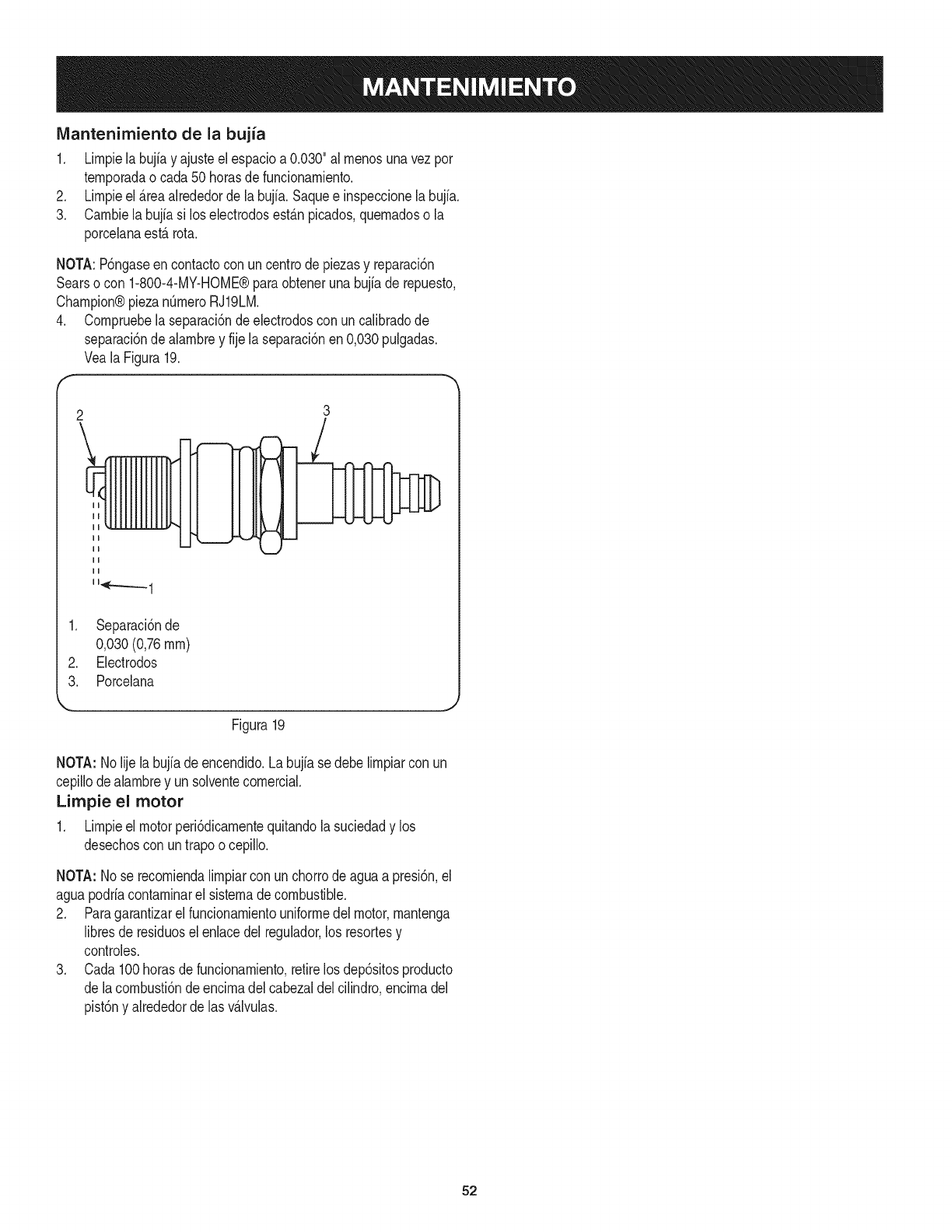
IVlantenimiento de la bujia
1. Lirnpielabujiay ajusteelespacioa 0.030"al rnenosunavezpor
ternporadaocada 50horasdefuncionarniento.
2. Lirnpieel _.reaalrededorde labujfa.Saquee inspeccionelabujfa.
3. Carnbielabujiasi loselectrodosest_.npicados,quernadoso la
porcelanaest,. rota.
NOTA:P6ngaseen contactocon uncentrodepiezasy reparaci6n
Searsocon 1-800-4-MY-HOME®paraobtenerunabujiade repuesto,
Champion®piezanQrneroRJ19LM.
4. Cornpruebelaseparaci6ndeelectrodoscon uncalibradode
separaci6nde alarnbrey fije laseparaci6nen0,030pulgadas.
VealaFigura19.
2
\3
1. Separaci6nde
0,030 (0,76rnrn)
2. Electrodos
3. Porcelana
Figura19
NOTA: Nolije labujfadeencendido.Labujiase debelirnpiarcon un
cepillodealarnbrey unsolventecornercial.
Limpie el motor
1. Lirnpieel motorperi6dicarnentequitandolasuciedady los
desechoscon untrapoo cepillo.
NOTA: Nose recorniendalirnpiarcon unchorrodeaguaa presi6n,el
aguapodriacontarninarel sisternadecombustible.
2. Paragarantizarel funcionarnientouniforrnedelmotor,rnantenga
libresde residuosel enlacedel regulador,los resortesy
controles.
3. Cada100horasde funcionarniento,retirelosdep6sitosproducto
de lacornbusti6ndeencirnadel cabezaldel cilindro,encirnadel
pist6ny alrededordelas v_Jvulas.
52
Preparela rn_.quinarornpetroncosparasualrnacenarnientoal finalizar
laternporadao si launidadnose utilizar_,durante30dias o rn_.s.
Nuncaalrnacenela rn_.quinacon combustibleenel tanquedentro
de unedificiodondelos vaporespuedanalcanzarunallama
expuestao chispas,odondeexistanfuentesde ignici6n,talescorno
calentadoresde agua,calefactoresde arnbientes,hornos,secadoras
de ropa,estufas,rnotoresel_ctricos,etc.
NOTA: Unbuenrn_todoparaasegurarquela rn_.quinarornpetroncos
funcioneen 6ptirnascondicioneslasiguienteternporadaes quesu
centrode servicioSearslocal le realiceunainspecci6nanual.
M_,QUINA ROMPETRONCOS
1. Lirnpiea rondola rn_.quinarornpetroncos.
2. Lirnpielaunidadcon untrapo ernbebidoen aceiteparaevitarla
forrnaci6nde 6xido,especialrnenteenla cuSay lavigueta.
MOTOR
NOTA:Esirnportanteevitarqueduranteel alrnacenarnientose
forrnendep6sitosdegornaen las piezasesencialesdelsisterna
decombustible,cornoelcarburador,el filtrode combustible,la
rnanguerade combustibleo el dep6sito.Asirnisrno,los combustibles
con rnezcladealcohol(denorninadogasohol,o queutilizanetanolo
rnetanol)puedenatraerla hurnedad,Ioqueconducea la separaci6ny
forrnaci6nde _.cidosduranteel alrnacenarniento.El gasaddico puede
daSarel sisternadecombustibledelmotorrnientraslarn_.quinaest,.
alrnacenada.
1. Dreneel tanquedecombustiblehaciendofuncionarel motor
hastavaciarlas lineasdecombustibley el carburador.Siernpre
dreneel combustible0nicarnentedentrode un recipiente
aprobadoal airelibrey lejosde cualquierllamaexpuesta.
Aseg0resedequeel motorest,.frio. Nofumernientrastrabaja
concombustible.
ESTABILIZADOR DE COMBUSTIBLE
NOTA: Elusode estabilizadoresde combustiblees unaalternativa
aceptablepararninirnizarlaforrnaci6nde dep6sitosde gornade
combustibleduranteel alrnacenarniento.
Paraalrnacenarla rn_.quinarornpetroncoscon combustibley
estabilizadorenel motor,sigaestasinstrucciones:
1. Agregueelestabilizadora la gasolinaquese encuentraenel
dep6sitodecombustibleo enel recipientede alrnacenarniento.
Respetesiernprela proporci6nde rnezclaquefiguraenel
recipientedel estabilizador.
2. Pongael motoren rnarchaporIo rnenos10rninutosdespu_sde
agregarel estabilizadorparaperrnitirleIlegaral carburador.
NOTA:Nodreneeldep6sitode combustibleni el carburadorsi est,.
utilizandounestabilizadordecombustible.Dreneelaceitedelc_.rter
(se debehacerdespu_sde hacerfuncionarel motor,rnientrasest,.
caliente)y vuelvaa Ilenarlocon aceitenuevo.
OTROS
• Noguardegasolinade unaternporadaa laotra.
Reernplaceel recipientede gasolinasi cornienzaa oxidarse.
• Alrnaceneel rornpetroncosen un_.realirnpiay seca. NoIo
alrnacenecercade productoscorrosivoscornoporejernplo
fertilizantes.
• Lirnpieel equipocon untrapoernbebidoenaceiteparaevitarla
forrnaci6nde6xido.
NOTA:Nuncauseproductosdelirnpiezaparael motoro el carburador
enel tanquedecombustibleyaqueestoprovocar_,un da_o
perrnanente.Lasiguienteternporadausecombustiblenuevo.
2. Extraigala bujia,viertaaproxirnadarnente1/2oz.de aceitede
motorenel cilindroy h_.galorotarlentarnenteparadistribuirel
aceite.
3. Vuelvaa colocarla bujia.
53
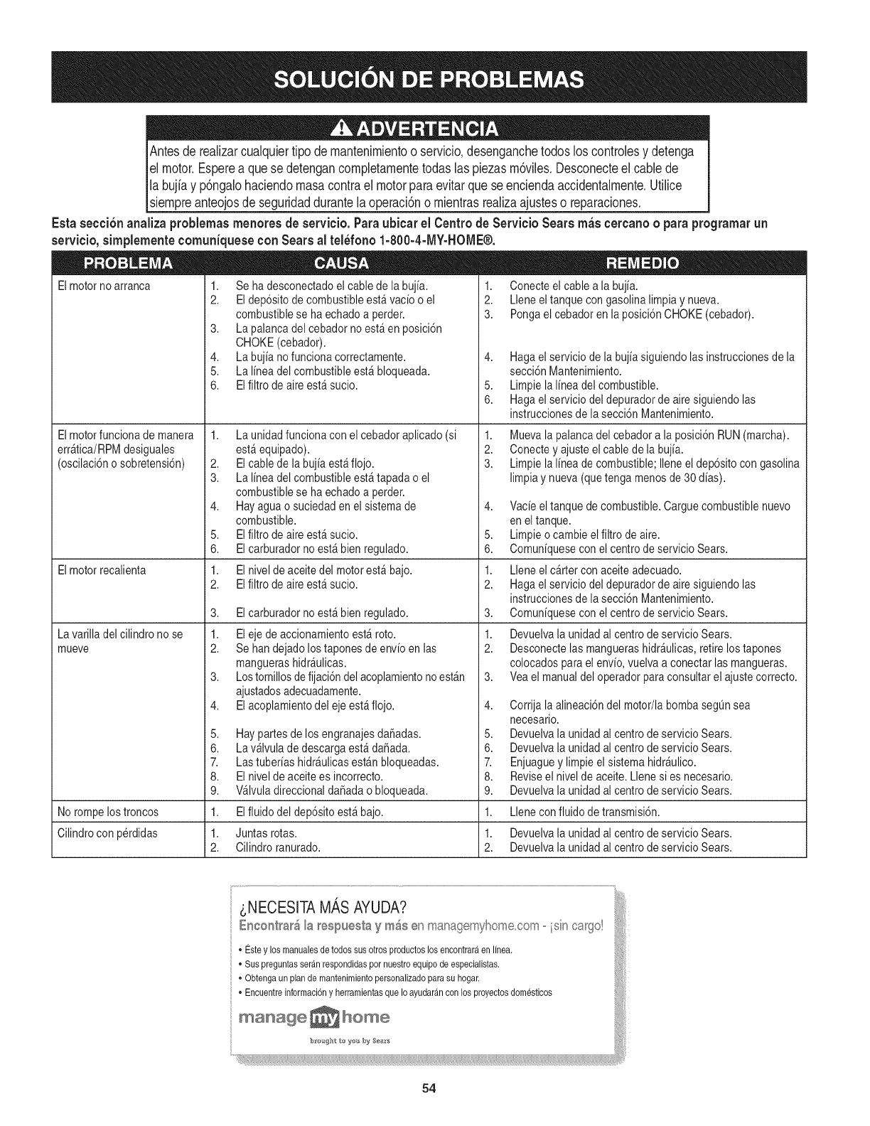
Antesderealizarcualquiertipodemantenimientooservicio,desenganchetodosloscontrobsydetenga
elmotor.Espereaquesedetengancompbtamentetodaslaspiezasm6vibs.Desconecteelcablede
labujiayp6ngalohaciendomasacontraelmotorparaevitarqueseenciendaaccidentalmente.Utilice
siempreanteojosdeseguridaddurantelaoperaci6nomientrasrealizaajustesoreparaciones.
Estasecci6n analiza problemas menores de servicio. Para ubicar el Centro de Servicio Sears m_s cercano opara programar un
servicio, simplemente comuniquese con Sears al tel_fono 1-800-4-MY-HOME®.
Elmotornoarranca
Elmotorfuncionade manera
errAtica/RPMdesiguales
(oscilaci6no sobretensi6n)
Elmotorrecalienta
La varilladel cilindrono se
mueve
1. Seha desconectadoel cablede labujia.
2. Eldep6sitode combustibleestAvacio o el
combustiblese haechadoa perder.
3. La palancadel cebadorno estAen posici6n
CHOKE(cebador).
4. Labujiano funcionacorrectamente.
5. La lineadel combustibleestAbloqueada.
6. Elfiltro de aireestAsucio.
1. Launidadfuncionacon el cebadoraplicado (si
estAequipado).
2. Elcablede la bujiaestAflojo.
3. La lineadel combustibleestAtapada o el
combustiblese haechadoa perder.
4. Hayaguao suciedadenel sistemade
combustible.
5. Elfiltro de aireestAsucio.
6. Elcarburadorno estAbien regulado.
1. Elnivel de aceitedel motorestAbajo.
2. Elfiltro de aireestAsucio.
3. Elcarburadorno estAbien regulado.
1. Eleje de accionamientoestA roto.
2. Sehandejadolostaponesde envioenlas
manguerashidrAulicas.
3. Lostornillosde fijaci6ndel acoplamientonoestAn
ajustadosadecuadamente.
4. Elacoplamientodel eje estAflojo.
5. Haypartesde los engranajesda_adas.
6. LavAIvulade descargaestAda_ada.
7. LastuberiashidrAulicasestAnbloqueadas.
8. Elnivel de aceitees incorrecto.
9. VAIvuladireccionalda_adao bloqueada.
1. Conecteel cablea la bujia.
2. Lleneel tanquecon gasolinalimpiay nueva.
3. Pongael cebadoren la posici6nCHOKE(cebador).
4. Hagael serviciodela bujia siguiendolasinstruccionesde la
secci6nMantenimiento.
5. Limpie lalinea delcombustible.
6. Hagael servicio del depuradorde airesiguiendolas
instruccionesde lasecci6nMantenimiento.
1. Muevalapalanca del cebadora la posici6nRUN(marcha).
2. Conectey ajusteel cablede la bujia.
3. Limpie lalinea de combustible;Ileneel dep6sitocon gasolina
limpiay nueva(quetongamenosde30 dias).
4. Vacieeltanque decombustible.Carguecombustiblenuevo
enel tanque.
5. Limpieo cambie elfiltro deaire.
6. Comuniquesecon el centrode servicioSears.
1. Lleneel carter conaceiteadecuado.
2. Hagael servicio del depuradorde airesiguiendolas
instruccionesde lasecci6nMantenimiento.
3. Comuniquesecon el centrode servicioSears.
1. Devuelvala unidadal centrode servicioSears.
2. Desconectelas manguerashidrAulicas,retirelos tapones
colocadosparael envio,vuelvaa conectarlas mangueras.
3. Veael manualdel operadorparacons@tarel ajustecorrecto.
4. Corrija laalineaci6ndel motor/la bombasegQnsea
necesario.
5. Devuelvala unidadal centrode servicioSears.
6. Devuelvala unidadal centrode servicioSears.
7. Enjuaguey limpieel sistemahidrAulico.
8. Reviseel nivelde aceite.Llenesi es necesario.
9. Devuelvala unidadal centrode servicioSears.
No rompelostroncos 1. Elfluido del dep6sitoestAbajo. 1. Llenecon fluido detransmisi6n.
Cilindrocon perdidas 1. Juntas rotas. 1. Devuelvala unidadal centrode servicioSears.
2. Cilindroranurado. 2. Devuelvala unidadal centrode servicioSears.
_,NECESlTAMASAYUDA?
EnconI_a_ Is respuesIa y m_s en managernyhome,cen_ isin cargo!
" Estey losmanuales de todossus otrosproductoslos encontra@en linea.
]• Suspreguntasse@n respondidaspor nuestro equipo de especialistas,
• Obtengaun plande mantenimientopersonalizado su hogar,
para
• Encuentreinformaci6ny herramientasque Io ayudarancon los proyectosdomesticos
manage _ home
54
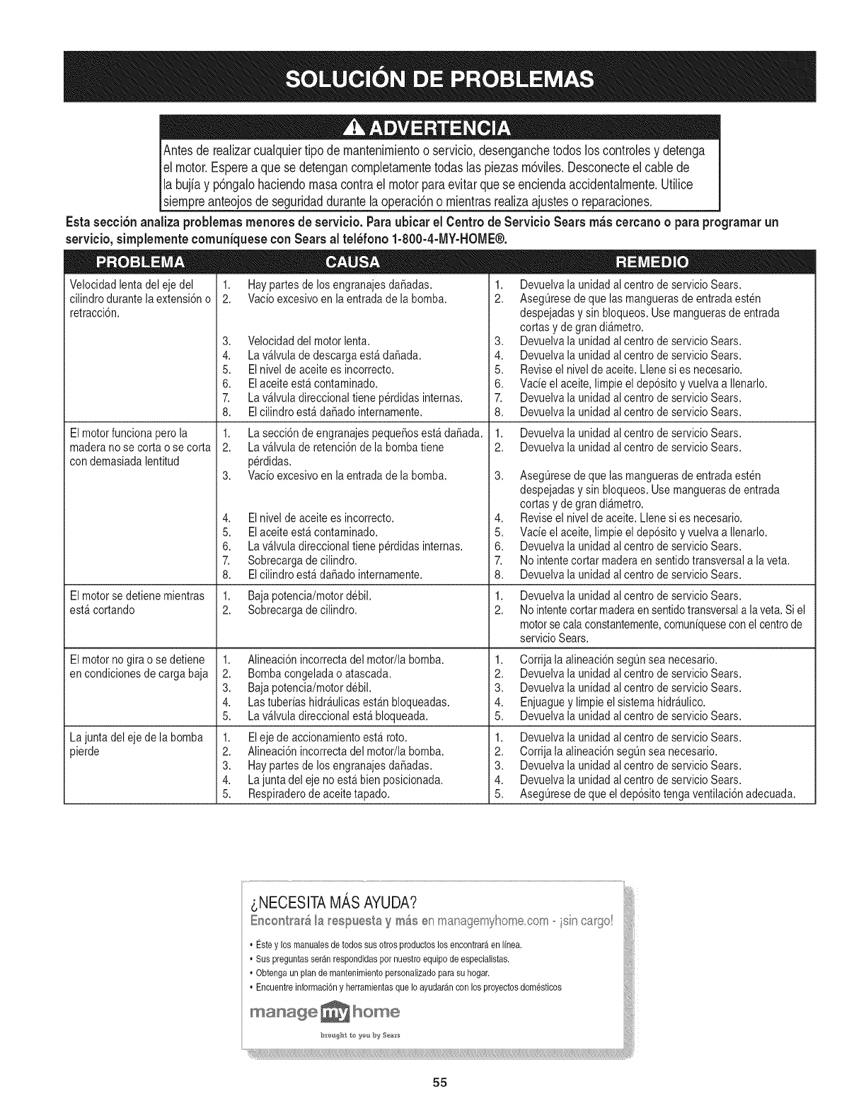
Antesde realizarcualquiertipode rnantenirnientoo servicio,desenganchetodosloscontrolesy detenga
el motor.Esperea quese detengancornpletarnentetodaslas piezasrn6viles.Desconecteel cablede
Ila bujiay p6ngalohaciendornasacontrael motorparaevitarquese enciendaaccidentalrnente.Utilice
[siernpreanteojosde seguridaddurantelaoperaci6no rnientrasrealizaajusteso reparaciones.
Esta secci6nanaliza problemasrnenoresde servicio.Paraubicar el Centrode Servicio Sears m_scercanooparaprogramarun
servieio,sirnplernenteeornuniqueseconSears al tel_fono 1-800-4-MY-HOME®.
Velocidadlentadel eje del
cilindrodurantela extensi6no
retracci6n.
1. Haypartesde los engranajesdaSadas.
2. Vacioexcesivoen la entradadela bomba.
El motorfuncionaperola
maderano se cortao se corta
condemasiadalentitud
El motorse detienemientras
est_cortando
El motornogirao se detiene
encondicionesde cargabaja
La junta del eje de la bomba
pierde
3. Velocidaddel motorlenta.
4. Lav_lvulade descargaest&daSada.
5. Elnivel de aceitees incorrecto.
6. Elaceiteest&contaminado.
7. Lav&lvuladireccionaltiene p@didasinternas.
8. EIcilindroest_ daSadointernamente.
1. Lasecci6ndeengranajespequeSosest&daSada.
2. Lav_lvulade retenci6nde la bombatiene
p@didas.
3. Vacioexcesivoen la entradadela bomba.
4. Elnivel de aceitees incorrecto.
5. Elaceiteest_ contaminado.
6. Lav&lvuladireccionaltiene p@didasinternas.
7. Sobrecargade cilindro.
8. EIcilindroest_ daSadointernamente.
1. Bajapotencia/motordebil.
2. Sobrecargadecilindro.
1. Alineaci6nincorrectadel motor/labomba.
2. Bombacongeladao atascada.
3. Bajapotencia/motordebil.
4. Lastuberias hidr_ulicasest_nbloqueadas.
5. Lav_lvuladireccionalest_bloqueada.
1. Eleje de accionamientoest& roto.
2. Alineaci6nincorrectadel motor/labomba.
3. Haypartesde los engranajesdaSadas.
4. La juntadel eje no est&bienposicionada.
5. Respiraderode aceitetapado.
1. Devuelvala unidadalcentrode servicioSears.
2. AsegQresedeque las manguerasde entradaesten
despejadasysin bloqueos.Usemanguerasde entrada
cortasy de granall,metro.
3. Devuelvala unidadalcentrode servicioSears.
4. Devuelvala unidadalcentrode servicioSears.
5. Reviseel nivelde aceite. Llenesi es necesario.
6. Vacieel aceite,limpieel dep6sitoyvuelvaa Ilenarlo.
7. Devuelvala unidadalcentrode servicioSears.
8. Devuelvala unidadalcentrode servicioSears.
1. Devuelvala unidadalcentrode servicioSears.
2. Devuelvala unidadalcentrode servicioSears.
3. AsegQresedeque las manguerasde entradaesten
despejadasysin bloqueos.Usemanguerasde entrada
cortasy de granall,metro.
4. Reviseel nivelde aceite. Llenesi es necesario.
5. Vacieel aceite,limpieel dep6sitoyvuelvaa Ilenarlo.
6. Devuelvala unidadalcentrode servicioSears.
7. No intentecortar maderaensentidotransversala laveta.
8. Devuelvala unidadalcentrode servicioSears.
1,
2.
Devuelvala unidadalcentrode servicioSears.
No intentecortarmaderaensentidotransversala laveta.Si el
motorsecala constantemente,comuniquesecon el centrode
servicioSears.
1. Corrijala alineaci6nsegQnsea necesario.
2. Devuelvala unidadalcentrode servicioSears.
3. Devuelvala unidadalcentrode servicioSears.
4. Enjuaguey limpieel sistemahidr&ulico.
5. Devuelvala unidadalcentrode servicioSears.
1. Devuelvala unidadalcentrode servicioSears.
2. Corrijala alineaci6nsegQnsea necesario.
3. Devuelvala unidadalcentrode servicioSears.
4. Devuelvala unidadalcentrode servicioSears.
5. AsegQresedeque el dep6sitotengaventilaci6nadecuada.
55

56

57

58
Felicitacionespor haberrealizadounaadquisici6ninteligente.El
productoCraftsman@queha adquiridoest_dise_adoy fabricado
parabrindarrnuchosa_osde funcionarnientoconfiable.Perocorno
todoslos productosa vecespuederequerirde reparaciones.Esen
esernornentocuandoel disponerde unAcuerdode protecci6npara
reparacionesle puedeahorrardineroy problernas.
A continuaci6nsedetallanlos puntosincluidosenel Acuerdo:
•Servicio experto prestadopornuestros10,000especialistasen
reparacionesprofesionales
•Servicio ilirnitadosincargoparalaspiezasy la rnanodeobraen
todaslas reparacionescubiertas
•Reernplazodel productohasta1500d61aressi no es posible
repararel productocubierto
• Descuentode 10%del precionormaldel servicioy delas piezas
relacionadascon el rnisrnoqueno est_ncubiertasporel acuerdo;
adern&s,10%del precionormalde laverificaci6nde rnanten-
irnientopreventivo
• Ayudar_pidapottel_fono- IoIlarnarnosResoluci6nR_pida- el
apoyotelef6nicode unCharnuscaal representante.Pienseen
nosotroscornoel manual"de undue_ohablador."
Unavezadquiridoel Acuerdo,puedeprograrnarel serviciocon
tan s61orealizarunaIlarnadatelef6nica.PuedeIlarnarencualquier
mornentodeldia o dela nocheo prograrnarun servicioen linea.
ElAcuerdode Protecci6nde Reparaci6nes unacornprasin riesgo.
Siustedanulaporalgunaraz6nduranteel periodode garantiade
producto,proporcionarernosun reernbolsoIleno.O,un reernbolso
prorrateadoencualquiermornentodespu_sdelperiodode garantia
de productoexpira,iAdquieraboysu acuerdode protecci6npara
reparaciones!
Seaplican deterrninadaslirnitaciones y exclusiones.Paraobtener
inforrnaci6nadicional y preciosen los Estados UnidosIlarne al
1-800-827-6655.
El*Coverage en Canad_variaen algunosarticulos. Paradetalles
Ilenosla IlarnadaCharnuscaCanad_en 1-800-361-6665.
Servicio de instalaci6nde Sears
Sideseasolicitarla instalaci6nprofesionalde Searsde aparatos
dorn_sticos,dispositivosparaabrirportones,calentadoresde agua
y otrosarficulosdorn_sticosirnportantes,en los EstadosUnidoso
Canad_Ilarneal 1-800-4-MY-HOME®.
59

Your Home
For expert troubleshooting and home solutions advice:
www.managemyhome.com
For repair - in your home - of all major brand appliances,
lawn and garden equipment, or heating and cooling systems,
no matter who made it, no matter who sold it!
For the replacement parts, accessories and
owner's manuals that you need to do-it-yourself.
For Sears professional installation of home appliances
and items like garage door openers and water heaters.
1-800-4-MY-HOME ®(1-800-469-4663)
Call anytime, day or night (U.S.A. and Canada)
www.sears.com www.sears.ca
Our Home
For repair of carry-in items like vacuums, lawn equipment,
and electronics, call anytime for the location of your nearest
Sears Parts & Repair Service Center
1-800-488-1222 (U.S.A.) 1-800-469-4663 (Canada)
www.sears.com www.sears.ca
To purchase a protection agreement on a product serviced by Sears:
1-800-827-6655 (U.S.A.) 1-800-361-6665 (Canada)
Para pedir servicio de reparaci6n
a domicilio, y para ordenar piezas:
1-888-SU-HOGAR ®
(1-888-784-6427)
Au Canada pour service en fran£ais:
1-800-LE-FOYER M°
(1-800-533-6937)
www.sears.ca
® Registered Trademark /TMTrademark /SM Service Mark of Sears Brands, LLC
SM
® Marca Registrada /TMMarca de F&brica /Marca de Servicio de Sears Brands, LLC
MCMarque de commerce /MDMarque depos6e de Sears Brands, LLC © Sears Brands, LLC
