MTD 31AS2B5 801 User Manual SNOW THROWER Manuals And Guides 1108389L
User Manual: MTD 31AS2B5-801 31AS2B5-801 MTD SNOW THROWER - Manuals and Guides View the owners manual for your MTD SNOW THROWER #31AS2B5801. Home:Lawn & Garden Parts:MTD Parts:MTD SNOW THROWER Manual
Open the PDF directly: View PDF ![]() .
.
Page Count: 18
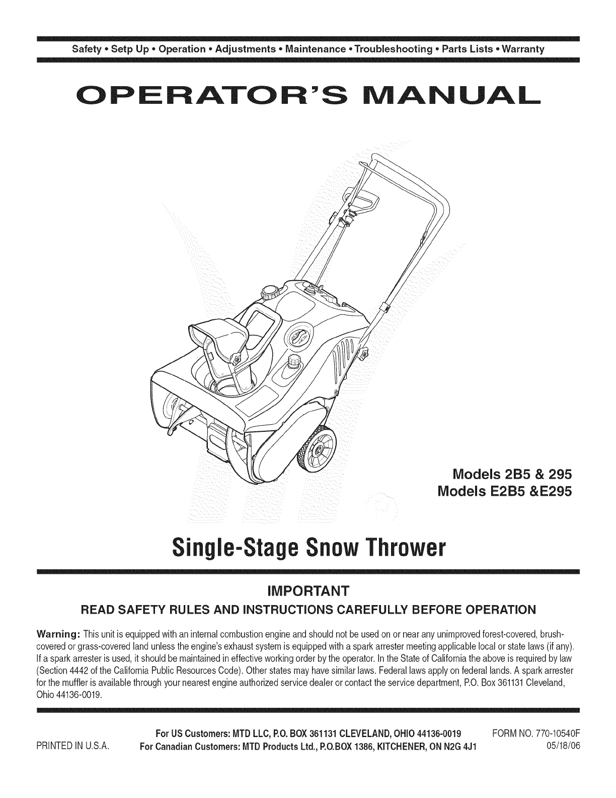
Safety • Setp Up • Operation • Adjustments • Maintenance • Troubleshooting • Parts Lists • Warranty
AOA AL
Models 2B5 & 295
Models E2B5 &E295
n le-StageSnowThrower
iMPORTANT
READ SAFETY RULES AND iNSTRUCTiONS CAREFULLY BEFORE OPERATION
Warning: Thisunit is equippedwithaninternalcombustionengineandshouldnot beusedon or nearany unimprovedforest-covered,brush-
coveredor grass-coveredlandunlesstheengine'sexhaustsystemis equippedwitha sparkarrestermeetingapplicablelocalor statelaws(if any).
If a sparkarresteris used,it shouldbemaintainedin effectiveworkingorder by the operator.In theStateof Californiathe aboveis requiredbylaw
(Section4442of the CaliforniaPublicResourcesCode).Otherstatesmayhavesimilarlaws.Federallawsapplyonfederallands.A sparkarrester
for the muffleris availablethroughyour nearestengineauthorizedservicedealeror contactthe servicedepartment,RO.Box361131Cleveland,
Ohio44136-0019.
PRINTEDIN U.S.A. ForUSCustomers:MTDLLC,P.O.BOX361131CLEVELAND,OHiO44136-0019
ForCanadianCustomers:MTD ProductsLtd.,P.O.BOX1386,KJTCHENER,ON N2G4J1
FORMNO.770-10540F
05/18/06
This Operator's Manual is an important part of your new snow thrower, it will help you assemble,
prepare and maintain the unit for best performance. Please read and understand what it says.
Table of
Safety Labels ...................................................... 3
Safe Operation Practices ................................... 4
Setting Up Your Snow Thrower .......................... 6
Know Your Snow Thrower .................................. 7
Operating Your Snow Thrower ........................... 8
Contents
Adjustments & Maintenance ........................... 10
Off-Season Storage .......................................... 12
Trouble Shooting .............................................. 13
illustrated Parts Lists ....................................... 14
Warranty ............................................................ 18
Finding and Recording Model Number
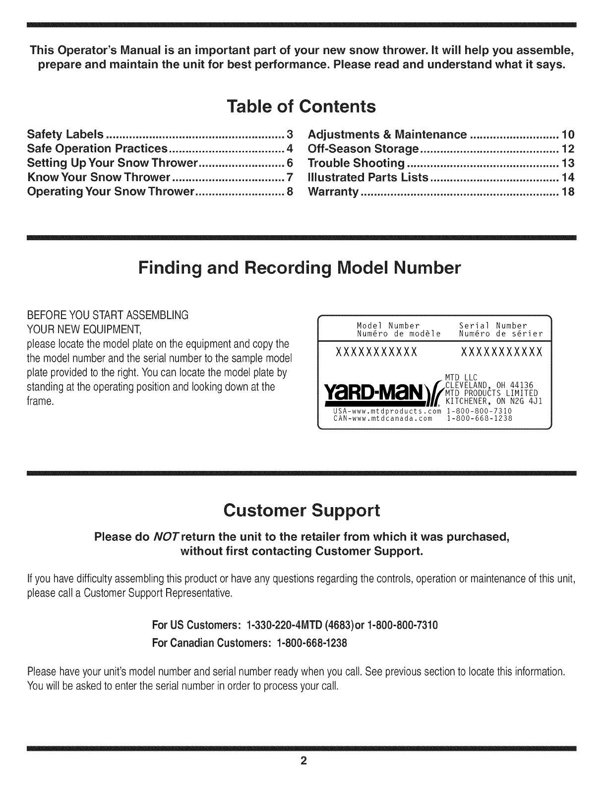
BEFOREYOU STARTASSEMBLING
YOUR NEW EQUIPMENT,
please locatethe model plate on the equipmentand copy the
the model number andthe serial number to the sample model
plate provided to the right. You can locatethe model plate by
standing at the operatingposition and looking down at the
frame.
Model Number Serial Number
Num6ro de mod61e Num6ro de s6rier
XXXXXXXXXXX XXXXXXXXXXX
MTD LLC
•,,A .... m,,,.\f CLEVELAND, OH 44136
Y_IIHUIMZrIN_//MTD PRODUCTS LIMITED
........... UL KITCHENER, ON N2G 4Jl
USA-www.mtdproducts.com 1-800-800-7310
CAN-www.mtdcanada. com 1-800-668-1238
Customer Support
Please do NOTretum the unit to the retailer from which it was purchased,
without first contacting Customer Support.
Ifyou havedifficulty assembling this product or have any questionsregarding the controls, operationor maintenanceof this unit,
please call a Customer Support Representative.
For US Customers: 1-330-220-4MTD (4683)or 1-800-800-7310
For Canadian Customers: 1-800-668-1238
Pleasehaveyour unit's model number and serial number ready when you call. See previoussection to locate this information.
Youwill be asked to enterthe serial number in order to processyour call.
2
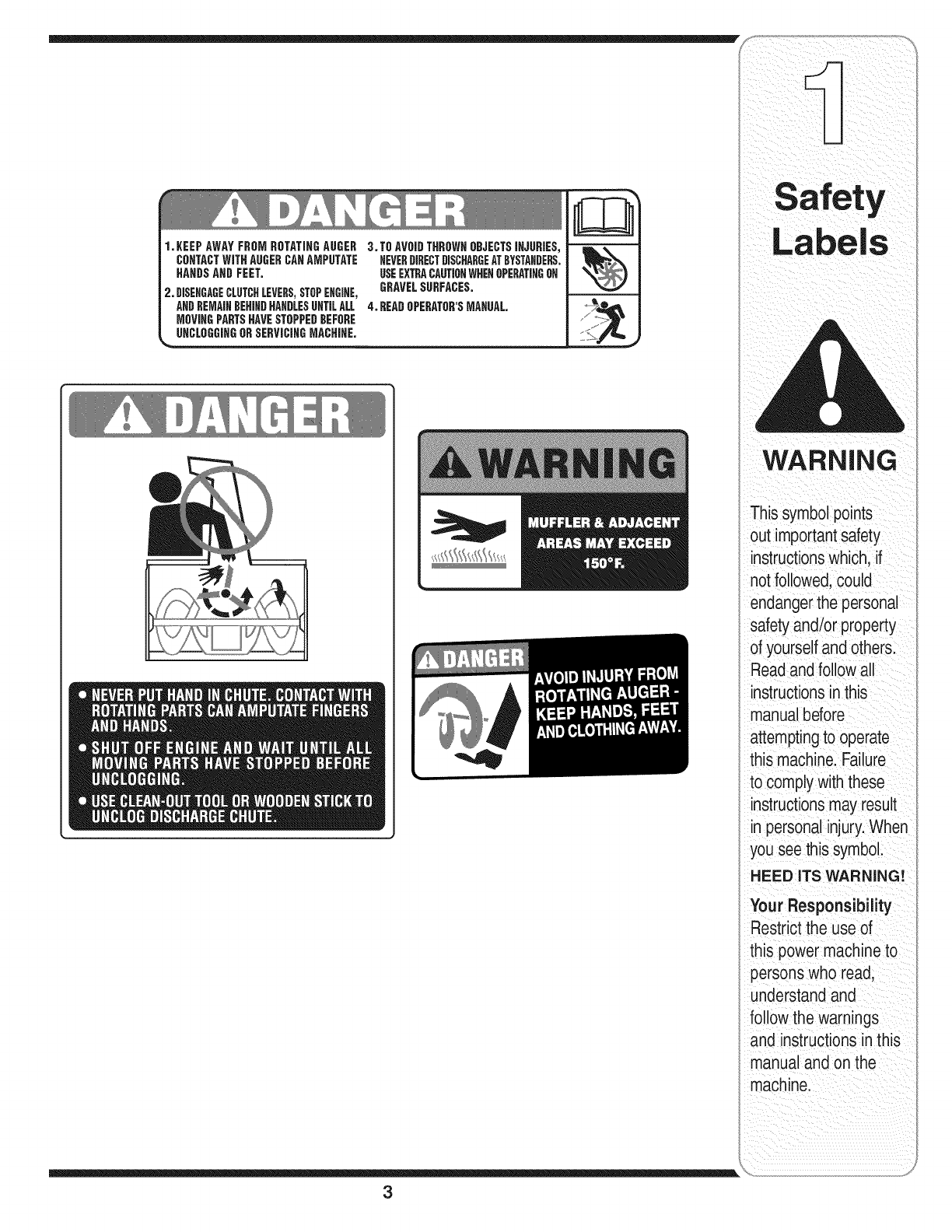
1.KEEPAWAYFROMROTATINGAUGER
CONTACTWiTHAUGERCAHAMPUTATE
HAHOSAND FEET.
2. DISEHGAGECLUTCHLEVERS,STOPEHGIHE,
ANDREMAINDEHIHDHAHBLESUNTILALL
MOVIHGPARTSHAVESTOPPEDBEFORE
UHCLOGGiHGORSERViCIHGMACHiHE.
3.TO AVOIDTHROWNOBJECTSIHJURIES,
NEVERDIRECTDISCHARGEATBYSTANDERS.
USEEXTRACAUTIONWHEHOPERATINGOH
GRAVELSURFACES.
4. BEADOPERATOR'SMAHUAL
3
i i l_I ii_ _ i _iii_! i _ _ii_ ii
WARNING
This symbolpoints
out importantsafety
instructionswhich, if
not followed,could
endangerthe personal
safetyand/or property
of yourself andothers.
Readandfollowall
instructionsinthis
manualbefore
attemptingto operate
this machine.Failure
to complywiththese
instructionsmay result
in personalinjury.When
you see this symbol.
HEED ITS WARNING!
Your Responsibility
Restrictthe use of
this power machineto
personswho read,
understand and
followthe warnings
and instructionsin this
manualand on the
machine.
WARNING
This symbolpoints
out importantsafety
instructionswhich, if not
followed,could endanger
the personalsafetyand/
i or propertyof yourself
andothers. Readand
followall instructions
inthis manualbefore
attemptingto operate
this machine.Failure
to complywiththese
instructionsmay result
in personalinjury.When
you see this symbol.
i HEED iTS WARNING!
Your Responsibility
i Restrictthe use of
this power machine
i to personswho read,
understand andfollow
the warnings and
instructionsin this
manualand on
the machine.
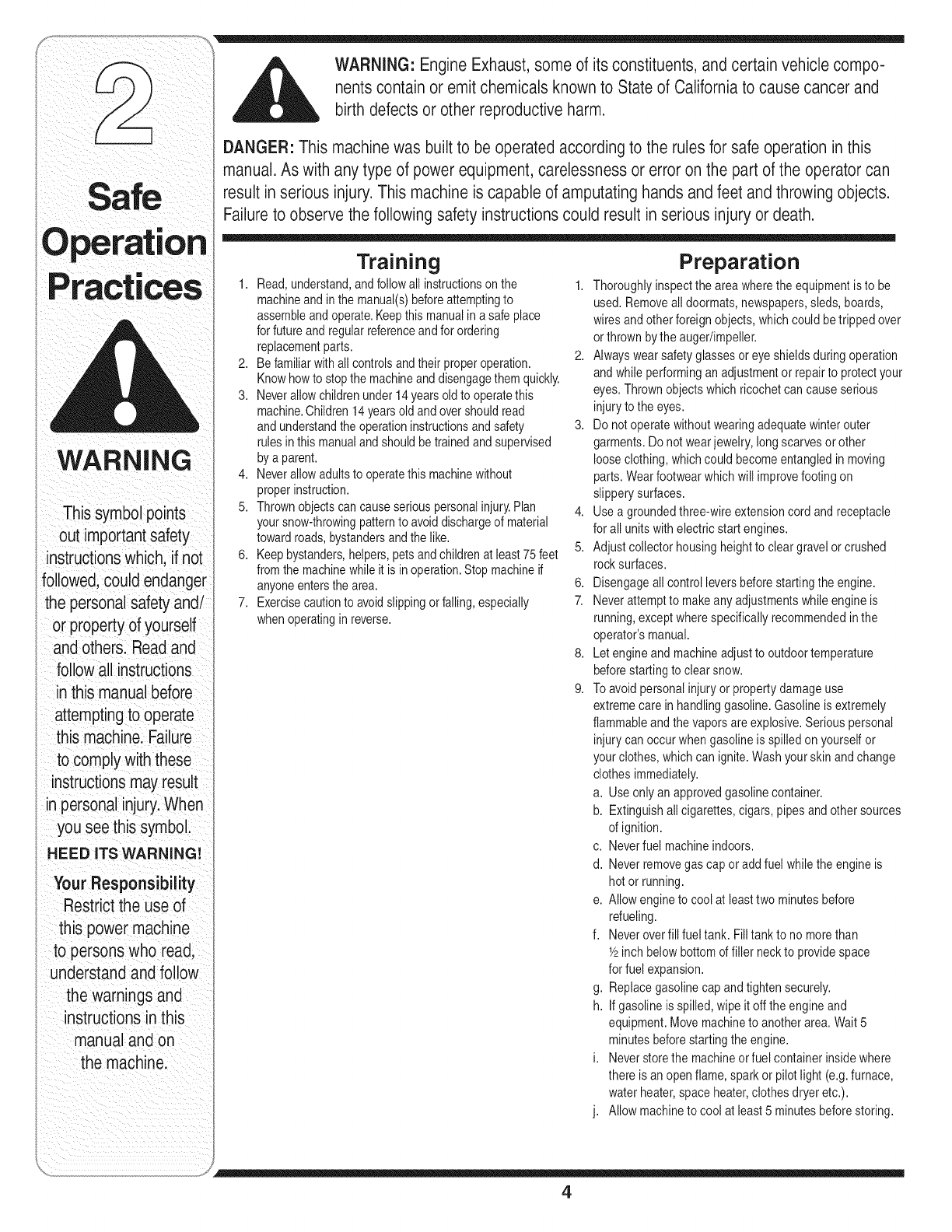
WARNING: Engine Exhaust,some of its constituents, andcertain vehicle compo-
nentscontain or emit chemicals knownto State of Californiato cause cancer and
birth defects or other reproductiveharm.
DANGER: This machinewas built to be operated according to the rulesfor safe operationin this
manual.As with any type of power equipment,carelessness or error on the part of the operator can
result in serious injury.This machine is capable of amputating hands andfeet andthrowing objects.
Failureto observe the followingsafety instructionscould result inserious injuryor death.
Training
1. Read,understand,andfollowall instructionson the 1.
machineandin themanual(s)beforeattemptingto
assembleand operate.Keepthis manualina safe place
forfutureand regularreferenceandfor ordering
replacementparts. 2.
2. Befamiliarwithall controlsandtheir properoperation.
Knowhowto stopthe machineanddisengagethem quickly.
3. Neverallowchildrenunder14yearsoldto operatethis
machine.Children14 yearsold andovershouldread
andunderstandtheoperationinstructionsandsafety 3.
rulesin thismanualand shouldbe trainedand supervised
bya parent.
4. Neverallowadultsto operatethis machinewithout
properinstruction.
5. Thrownobjectscancauseseriouspersonalinjury.Plan 4.
yoursnow-throwingpatternto avoiddischargeof material
towardroads,bystandersandthe like.
6. Keepbystanders,helpers,petsandchildrenat least 75feet 5.
fromthe machinewhileit is in operation.Stopmachineif
anyoneentersthe area. 6.
7. Exercisecautionto avoidslippingor falling,especially 7.
whenoperatingin reverse.
8,
9.
Preparation
Thoroughlyinspectthe areawherethe equipmentis to be
used. Removeall doormats,newspapers,sleds,boards,
wiresand otherforeignobjects,whichcouldbetripped over
orthrownbythe auger/impeller.
Alwayswearsafetyglassesor eyeshieldsduringoperation
andwhile performinganadjustmentorrepairto protectyour
eyes.Thrownobjectswhich ricochetcan cause serious
injuryto the eyes.
Do notoperatewithoutwearingadequatewinterouter
garments.Do notwearjewelry,longscarvesorother
looseclothing,whichcould becomeentangledin moving
parts.Wearfootwearwhich willimprovefootingon
slipperysurfaces.
Usea groundedthree-wireextensioncordand receptacle
forall units withelectric startengines.
Adjustcollectorhousingheightto cleargravel orcrushed
rocksurfaces.
Disengageallcontrolleversbeforestartingthe engine.
Neverattemptto makeanyadjustmentswhileengineis
running,exceptwherespecificallyrecommendedinthe
operator'smanual.
Letengine andmachineadjustto outdoortemperature
beforestartingto clearsnow.
Toavoidpersonalinjuryor propertydamage use
extremecare in handlinggasoline.Gasolineis extremely
flammableand thevaporsare explosive.Seriouspersonal
injurycan occur whengasolineisspilledon yourselfor
yourclothes,which canignite.Washyourskin andchange
clothesimmediately.
a. Useonly an approvedgasolinecontainer.
b. Extinguishallcigarettes,cigars, pipesandothersources
of ignition.
c. Neverfuel machineindoors.
d. Neverremovegascap oradd fuelwhilethe engineis
hotor running.
e. Allowengineto coolat leasttwo minutesbefore
refueling.
f. Neveroverfill fuel tank. Filltankto nomorethan
Y2inch below bottomoffiller neckto providespace
for fuel expansion.
g. Replacegasolinecap andtightensecurely.
h. If gasolineis spilled,wipe itoff theengineand
equipment.Movemachineto anotherarea.Wait5
minutesbeforestartingthe engine.
i. Neverstorethe machineorfuel containerinsidewhere
there is an openflame, sparkor pilot light (e.g.furnace,
waterheater,spaceheater,clothesdryeretc.).
j. Allowmachineto cool at least5 minutesbeforestoring.
4
Operation
1. Do notput handsor feet nearrotatingparts,inthe
auger/impellerhousingorchute assembly.Contactwiththe
rotating partscan amputatehandsand feet.
2. Theauger/impellercontrolleveris a safetydevice.Never
bypassits operation.Doingso makesthe machineunsafe
and maycausepersonalinjury.
3. Thecontrolleversmustoperateeasily in bothdirections
and automaticallyreturnto the disengagedpositionwhen
released.
4. Neveroperatewith a missingordamagedchuteassembly.
Keep allsafetydevicesin placeandworking.
5. Neverrun anengineindoorsor ina poorly ventilatedarea.
Engineexhaustcontainscarbonmonoxide,an odorlessand
deadlygas.
6. Do notoperate machinewhileunderthe influenceof alcohol
or drugs.
7. Mufflerand enginebecomehotandcancausea burn.Do
nottouch.
8. Exerciseextremecaution whenoperatingonor crossing
gravel surfaces.Stayalert for hidden hazardsor traffic.
9. Exercisecautionwhenchangingdirectionandwhile
operatingon slopes.
10.Planyour snow-throwingpatternto avoiddischargetowards
windows,walls,carsetc.Thus,avoidingpossibleproperty
damageor personalinjurycaused bya ricochet.
11.Neverdirectdischargeat children,bystandersandpets or
allowanyoneinfront of the machine.
12.Do notoverloadmachinecapacityby attemptingto clear
snow at toofast of a rate.
13.Neveroperatethis machinewithoutgood visibility or light.
Alwaysbe sure of yourfootingand keepa firmhold onthe
handles.Walk,neverrun.
14.Disengagepowerto theauger/impellerwhentransporting
or not inuse.
15.Neveroperatemachineat hightransportspeeds onslippery
surfaces.Lookdownand behindand usecarewhen
backing up.
16.Ifthe machineshould startto vibrateabnormally,stopthe
engine,disconnectthespark plugwire andground it against
the engine.Inspectthoroughlyfor damage.Repairany
damagebeforestartingandoperating.
17.Disengageall controlleversand stopenginebeforeyou
leavetheoperatingposition(behindthe handles).Wait
until the auger/impellercomesto a completestopbefore
uncloggingthechute assembly,makinganyadjustments,or
inspections.
18.Neverput yourhand inthe dischargeorcollector openings.
Alwaysuse theclean-outtool providedto unclogthe
dischargeopening.Do notunclogchute assemblywhile
engineis running.Shutoffengineand remainbehind
handlesuntil allmovingparts havestoppedbefore
unclogging.
19.Use onlyattachmentsand accessoriesapprovedbythe
manufacturer(e.g.wheelweights,tire chains,cabsetc.).
20. Ifsituationsoccur whichare notcoveredinthis manual,
usecare and goodjudgment.Contactyour dealerorcall
(800) 800-7310for assistanceandthe nameof your nearest
servicingdealer..
Maintenance & Storage
1. Nevertamper withsafetydevices.Checktheir proper
operationregularly.Referto the maintenanceand
adjustmentsectionsof this manual.
2. Beforecleaning,repairing,or inspectingmachine
disengageall controlleversandstopthe engine.Wait until
theauger/impellercome to a completestop.Disconnectthe
sparkplugwire and groundagainstthe engineto prevent
unintendedstarting.
3. Checkbolts and screwsfor propertightness at frequent
intervalsto keepthe machinein safe workingcondition.
Also,visuallyinspectmachinefor anydamage.
4. Do notchangethe enginegovernorsettingor over-speed
theengine.The governorcontrolsthemaximumsafe
operatingspeed of theengine.
5. Snowthrowershaveplatesand skidshoesare subjectto
wearanddamage.Foryoursafetyprotection,frequently
checkallcomponentsand replacewith originalequipment
manufacturer's(OEM) partsonly."Useof partswhich do
notmeetthe originalequipmentspecificationsmayleadto
improperperformanceandcompromisesafety!"
6. Checkcontrols periodicallyto verify theyengageand
disengageproperlyandadjust, if necessary.Referto the
adjustmentsection inthis operator'smanualfor instructions.
7. Maintainor replacesafetyandinstructionlabels,as
necessary.
8. Observeproperdisposallawsandregulationsfor gas,oil,
etc. to protectthe environment.
9. Priorto storing,run machinea few minutestoclearsnow
frommachineand preventfreezeup of auger/impeller.
10.Neverstorethe machineorfuel containerinsidewhere
thereis an openflame,sparkor pilot lightsuch as a water
heater,furnace,clothesdryeretc.
11.Alwaysreferto theoperator'smanualfor properinstructions
onoff-seasonstorage.
Do not modify engine
Toavoidseriousinjuryordeath,donot modifyengineinany
way.Tamperingwiththegovernorsettingcan leadto a runaway
engineandcauseit to operateat unsafespeeds.Nevertamper
withfactorysettingof enginegovernor.
Notice regarding Emissions
Engineswhichare certifiedto complywithCaliforniaandfederal
EPAemissionregulationsfor SORE(SmallOff RoadEquipment)
arecertifiedto operateon regularunleadedgasoline,and
mayincludethefollowingemissioncontrolsystems:Engine
Modification(EM)andThreeWayCatalyst(TWO)ifso equipped.
Your Responsibility
Restrictthe useof this powermachineto personswho read,
understandandfollowthe warningsandinstructionsinthis
manualandonthe machine.
WARNING
This symbolpoints
out importantsafety
instructionswhich, if not
followed,couldendanger
the personalsafetyand/
or propertyof yourself
and others.Readand
followall instructions
in this manualbefore
attemptingto operate
this machine.Failure
to complywiththese
instructionsmayresult
in personal injury.When
you seethis symbol.
HEED iTS WARNING!
Your Responsibility
Restrictthe use of
this power machine
to personswho read,
understandand follow
the warnings and
instructions inthis
manualand on
the machine.
5
NOTE:This Operator's
Manualcovers several
models.
Notall features refer-
enced inthis manual
are applicable to all
snow thrower models.
I NOTE: All references
i to left or right side of
the snow thrower is
from the operating
I positiononly.
i IMPORTANT:
i Do not use the
chute handle to lift
the snow thrower.
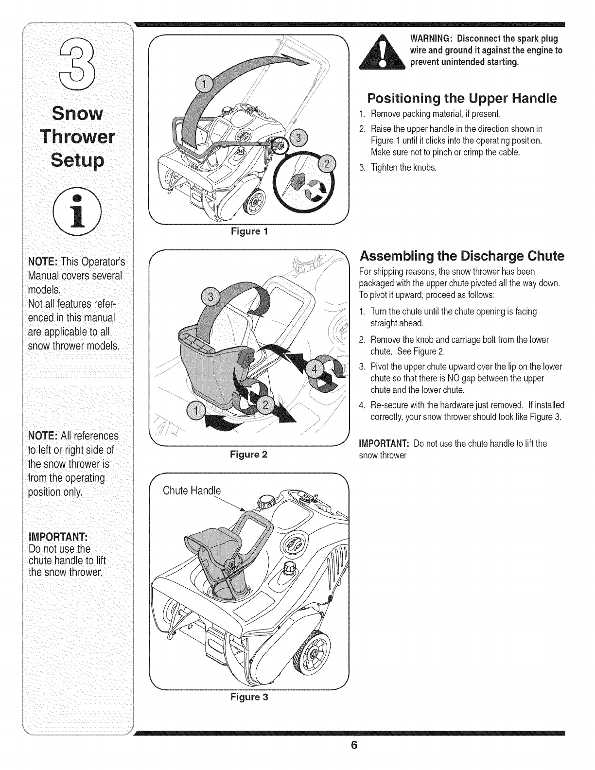
Positioning the Upper Handle
1. Removepackingmaterial,if present.
2. Raisethe upperhandleinthe directionshownin
Figure1 untilit clicksintothe operatingposition.
Makesure notto pinchor crimpthe cable.
3. Tightenthe knobs.
Figure 1
f
Chute Handle
Figure 2
Figure 3
Assembling the Discharge Chute
For shippingreasons,the snowthrowerhasbeen
packagedwiththe upperchutepivotedall the waydown.
Topivotit upward,proceedas follows:
1. Turnthe chuteuntilthe chuteopeningis facing
straightahead.
2. Removetheknob andcarriageboltfromthe lower
chute. SeeFigure2.
3. Pivotthe upperchuteupwardoverthe lip onthe lower
chuteso thatthere is NOgap betweenthe upper
chuteandthe lowerchute.
4. Re-securewiththe hardwarejust removed. If installed
correctly,your snowthrowershouldlook like Figure3.
IMPORTANT:Do not usethe chutehandleto liftthe
snowthrower
6
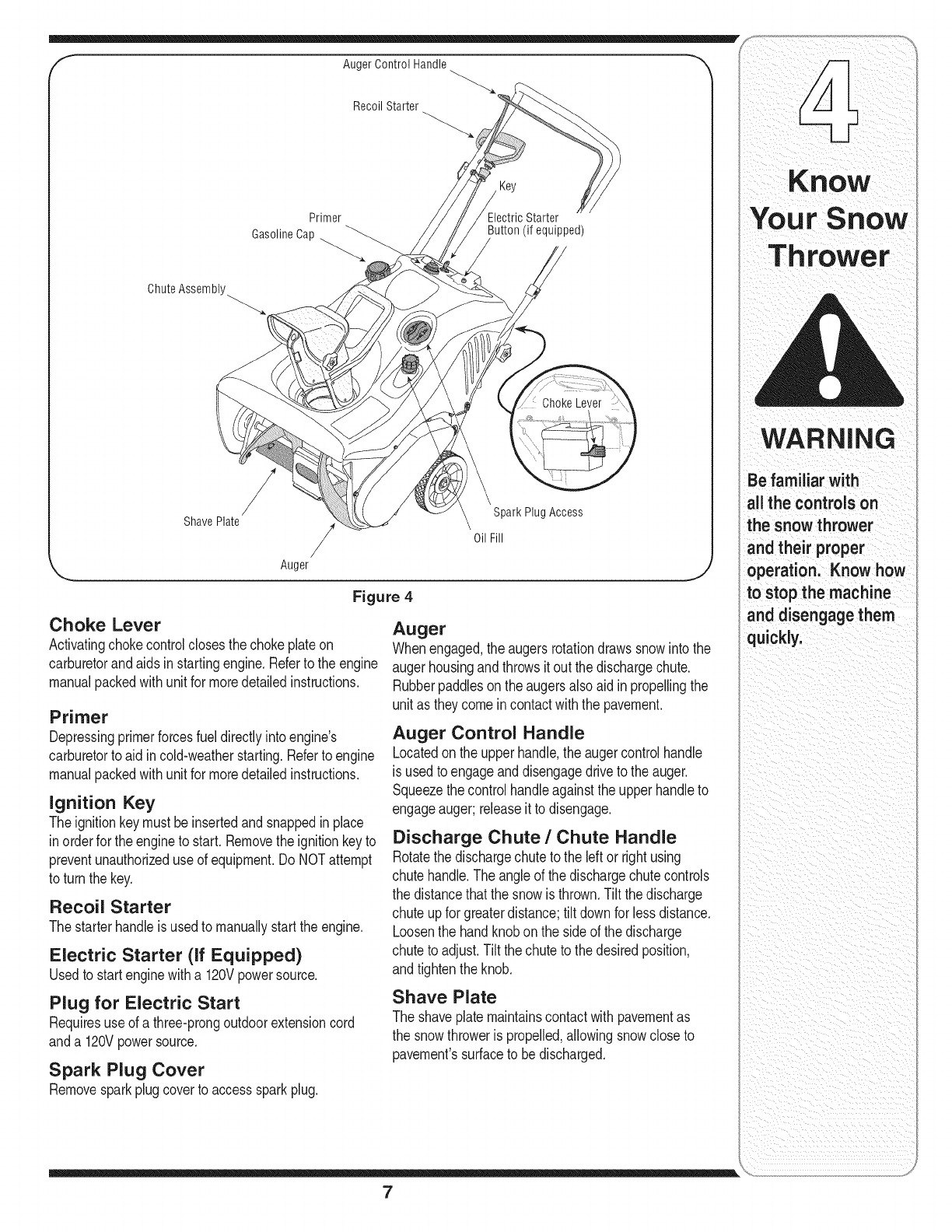
ChuteAssembly_
Recoil Starter
Primer
GasolineCap Button (if equipped)
Shave Plate Spark Plug Access
Oil Fill
Auger
Figure 4
Choke Lever
Activatingchokecontrolclosesthechokeplateon
carburetorandaids in startingengine.Referto the engine
manualpackedwith unitfor moredetailedinstructions.
Primer
Depressingprimerforcesfueldirectlyinto engine's
carburetorto aid incold-weatherstarting.Referto engine
manualpackedwith unitfor moredetailedinstructions.
Ignition Key
The ignitionkeymust beinsertedandsnappedin place
in orderfor the engineto start.Removethe ignitionkeyto
preventunauthorizeduseof equipment.Do NOTattempt
to turn the key.
Recoil Starter
The starterhandleis usedto manuallystartthe engine.
Electric Starter (if Equipped)
Usedto startenginewitha 120Vpowersource.
Plug for Electric Start
Requiresuseof a three-prongoutdoorextensioncord
anda 120Vpowersource.
Spark Plug Cover
Removesparkplugcoverto accesssparkplug.
Auger
Whenengaged,the augersrotationdrawssnowinto the
augerhousingandthrowsit out the dischargechute.
Rubberpaddleson the augersalso aidin propellingthe
unitas theycomeincontactwiththe pavement.
Auger Control Handle
Locatedon the upperhandle,the augercontrolhandle
is usedto engageanddisengagedriveto the auger.
Squeezethecontrolhandleagainsttheupperhandleto
engageauger;releaseit to disengage.
Discharge Chute /Chute Handle
Rotatethe dischargechuteto the leftor right using
chutehandle.Theangleof the dischargechutecontrols
the distancethatthe snowis thrown.Tilt the discharge
chuteupfor greaterdistance;tiltdownfor lessdistance.
Loosenthe handknobonthe side of the discharge
chuteto adjust.Tilt thechuteto the desiredposition,
andtightenthe knob.
Shave Plate
The shaveplatemaintainscontactwithpavementas
the snowthroweris propelled,allowingsnowcloseto
pavement'ssurfaceto bedischarged.
WARNING
Be familiar with
allthe controls on
tahesnow thrower
nd their proper
operation. Know how
to stop the machine
anddisengage them
quickly.
7

WARNING
Read, understand,
and follow all instruc-
tions and warnings
on the machine and
in this manual before
operating.
Use extreme care
when handling
gasoline. Gasoline is
extremely flammable
and the vapors are
i explosive. Neverfuel
the machine indoors
or while the engine
iis hot or running.
i Extinguish cigarettes,
cigars, pipes and
other sources of
ignition.
The electric starter
must be used with a
properly grounded
three-prong
receptacle at all
times to avoid the
ipossibilityof electric
ishock. Follow all
iinstructionscarefully
prior to operating the
electric starter.
Before Starting
1. Thesparkplugwirewasdisconnectedfor safety.
Attachsparkplugwireto sparkplugbeforestarting.
IMPORTANT:Forcompleteanddetailedengine
starting,stoppingand storinginstructions,it is
recommendedthatyou readthe enginemanualalso
includedwiththis unit.
Gas and Oil Fill-Up
1. Checkoilandgasolinelevelandadd if necessary.
Followrelatedinstructionsinthe separateengine
manualpackedwithyoursnowthrower.
_ARNING:Useextremecare when
handlinggasoline. Gasoline is
extremely flammable and the vapors
are explosive. Neverfuel the machine
indoorsor while the engineis hot or
running.Extinguish cigarettes, cigars,
pipesand other sources of ignition.
To Start Engine
1. Insertignitionkeyintoslot.
2. Nowfollowthe instructionsbelowas it pertainsto
yourunit.SeeFigure4for locationof controls
Electric Starter (if so equipped)
WARNING:Theelectricstartermust
be used witha properly groundedthree-prong receptacleat all times to
avoid the possibilityof electric shock.
Follow all instructionscarefullyprior
to operating the electric starter.
1. Theelectricstarteris equippedwitha grounded
three-wirepowercord andplug,andis designedto
operateon 120voltAC householdcurrent.
2. Determinethatyour housewiringis a three-wire
groundedsystem.Aska licensedelectricianif you
arenotcertain.
3. If your home wiringsystem is not a three-wire
grounded system, do not usethiselectricstarter
underany conditions.
4. If your home electricalsystemis grounded, but
a three-holereceptacleis not available,oneshould
beinstalledby a licensedelectricianbeforeusingthe
electricstarter.
5. If you have a grounded three-prong receptacle,
proceedas follows:
6. MoveChokeControlto "Full"position.
7. Pushprimerslowly,three(3) times,makingsure to
coverventholewhenpushing.
8. Connectpowercord to switchboxondash panel.
Plugthe otherendof powercord intoa three-prong
120-volt,grounded,AC receptacle.
f
_,ugerControl Handle
RecoilStarter
Primer
Gasoline _
Cap
\
Key
Ele( Starter |
Button if equipped)l
Cap Plug j)
Figure 5
9. Pushstarterbuttonto crankengine.As youcrankthe
engine,movechokeleverto FULLchokeposition.
10.Whenenginestarts,releasestarterbutton,andmove
chokegraduallyto OFRif enginefalters,movechoke
immediatelyto FULLandthengraduallyto OFR
11.Whendisconnectingthe powercord,always unplug
from the three-prong receptacle first, and then
from the snow thrower.
Recoil Starter
1. Movechokeleverto FULLchokeposition(coldengine
start).
2. If engineiswarm,placechokeinOFFpositioninstead
of FULL.
3. Pushprimerbuttonslowlytwoorthreetimes forcold
enginestart.
4. If engineiswarm,pushprimerbuttononlyonce.
NOTE:Alwayscoverventholein primerbuttonwhen
pushing.Additionalprimingmaybe necessaryfor first
start if temperatureis below150F (-90C).
5. Graspstarterhandleandpullropeout slowly,until it
pullsslightlyharder.Let roperewindslowly.
6. Pullstarterhandlerapidly.Do notallowhandleto snap
back.Allowit to rewindslowlywhilekeepinga firm
holdonthe starterhandle.
7. As enginewarmsup andbeginsto operateevenly,
rotatechokeleverslowlyto OFFposition.If engine
falters,returnto FULLchoke,then slowlymoveto OFF
position.
8

To Stop Engine Operating Tips
1. To stopengine,turnignitionkeycounter-clockwise.
Disconnectthe sparkplugwirefrom the sparkplug
to preventaccidentalstartingwhile equipmentis
unattended.
Tohelp preventpossiblefreeze-upof starter,
proceedas follows:
1. Runenginefor afew minutesbeforestoppingto help
dry off anymoistureon the engine.
2. Electric Starter (optional}: Connectpowercordto
switchboxon engine,thento 120voltAC receptacle.
Withthe enginerunning,pushstarterbuttonandspin
the starterfor severalseconds.The unusualsound
madeby spinningthe starterwill not harmengineor
starter.Disconnectthe powercordfrom receptacle
first,andthen fromswitchbox.
3. RecoilStarter: Withenginerunning,pullstarterrope
witha rapid,continuousfullarmstrokethreeorfour
times.Pullingthestarterropewillproducea loudclatter-
ingsound,whichis notharmfulto theengineorstarter.
4. Wipeall snowand moisturefromthe carburetorcover
inthe areaof thecontrollevers.Also,movecontrol
leversbackandforthseveraltimes.Leavechoke
controlinthe FULLchokeposition.
5. Removeignitionkeyanddisconnectsparkplugwireto
preventaccidentalstarting.
Operating the Snow Thrower
The pitchof thechuteassemblycontrolstheangleat
whichthe snowisthrown.Adjustthe chuteassemblyby
followingthe instructionsbelow.
1. Loosenthewing knobfoundonthe left sideof the
chuteassemblyandpivotthe upperchuteupwardor
downwardto the desiredpitch.Retightenthe wing
knob beforeoperatingthe snowthrower.
2. Positionthe chuteassemblyopeningby usingthe
ChuteHandleto throwthe snowinthedesireddirec-
tion.See Figure6.
1. Dischargesnowdownwindwheneverpossible.
Slightlyoverlapeachpreviouslyclearedpath.
2. Liftinguponthe handlewill allowthe rubberon the
augersto propelthe snowthrowerforward.Pushing
downwardon the handlewill raisethe augersoff the
groundandstopforwardmotion.
NOTE: Excessiveupwardpressureon the handlewill
resultinprematurewearonthe rubberaugerblades
whichwouldnot becoveredbywarranty.
3. Runthe enginefor a fewminutesbeforestoppingto
helpdry anymoistureonthe engine.
4. Cleanthe snowthrowerthoroughlyaftereach use.
.._ J
Figure 6
WARNING
Muffler,engineand
surroundingareas
become hot and
causeaburn:
Do not touch,
IMPORTANT:
For complete and
detailed engine
starting, stopping and
storing instructions,
it is recommended
that you read the
_=nginemanual also
includedwith
this unit.
NOTE:
Excessive upward
pressure on the
handle will result in
premature wear
on the rubber
auger blades which
would not be covered
by warranty.
9

MaintenanCe
WARNING
Disconnect the
spark plug wire
and ground it against
the engine to prevent
unintended starting.
NEVER attempt
to make any
adjustments while
I the engine is
running, except
where specified in
the operator's
manual.
Before servicing,
repairing, or
inspecting,
disengage the
control bail and
stop engine. Wait
i until all moving
i parts have come to a
complete stop.
_ARNING:NEVERattempt to make
any adjustments while the engineis
running,exceptwherespecified inthe
operator'smanual.
Shave Plate
1. Tocheckthe adjustmentof the shaveplate,placethe
uniton a levelsurface.The wheels,shaveplateand
augersshouldallcontactlevelsurface.Notethatif the
shaveplateis adjustedtoo high,snowmayblowunder
the housing.Ifthe shaveplatewearsout excessively,
orthe unit doesnot self-propel,the shaveplatemay
betoo lowand needsto beadjusted.
NOTE:On newunitsorunitswitha newshaveplate
installed,the augersmaybeslightlyoff theground.
2. Toadjust,tip the snowthrowerbacksothat it restson
the handle.Loosenthe four locknutsand boltswhich
securethe shaveplateto the housing.See Figure7.
Movethe shaveplateto desiredpositionand retighten
the nutsandboltssecurely.
Figure 7
/
Replacing Shave Plate
Theshaveplate isattachedto the bottomof theauger
housingandis subjectto wear.It shouldbechecked
periodically.Therearetwo wearingedgesandthe shave
platecan bereversed.Referto Figure7.Toreplaceor
reversethe shaveplateproceedas follows.
,
2.
,
4. Tightensecurely.
Removethecarriageboltsand hexlocknutswhich
attachit to the snowthrowerhousing.
Installnewshaveplate(or reverse),makingsurethe
headsof thecarriageboltsare onthe insideof the
housing.
Adjustthe shaveplateaccordingto instructionsabove
Control Cable
As a resultof both thecontrolcable andthedrive belt
stretchingdueto wear,periodicadjustmentsmaybe
necessary.
If the augerseemsto hesitatewhenrotatingwhilethe
enginemaintainsa constantspeed,an adjustmentis
necessary.Proceedas follows:
Theupperholeinthe controlhandleprovidesfor an
adjustmentincabletension.Toadjust,disconnectthe
endof controlcablefromthe bottomholeinthe control
handleand reinsertit inthe upperhole.Insertthe cable
fromtheoutsideas shownin Figure8. Testthe snow
throwerto seeif thereis a noticeabledifference.
Figure 8 Carburetor
,__ WARNING:If any adjustments needto
be made to the enginewhile the engine
is running(e.g. carburetor), keep
clear of all moving parts.Becareful of
muffler, engine and other surrounding
heated surfaces.
1. Referto the separateenginemanual,packedwith
yourunit,for carburetoradjustmentinformation.
10

Replacing Belt
_il ARNING:Before servicing,repairing,
or inspecting,disengage the control
bail and stop engine.Waituntil all
moving partshave come to a complete
stop. Disconnect spark plug wire and
ground it against the engine to prevent
unintended starting.
Removethe beltcover by removingfivehexscrews.See
Figure9. Thensimplypullthe beltoff by graspingit from
the bottomof the augerpulleyandpullingoff. Onceyou
removethe beltfromthe pulleys,youcan pushdownon
the idlerpulleyto releasethe belt fromunderbelt keeper.
To replacethe beltfollowtheseinstructionsandreferto
Figure10:
1. Pushdownon the Idlerpulley.
2. Putbelton top of the augerpulleyunderbelt keeper.
3. Threadbeltaroundenginepulley.
4. Pushbeltoverbottomof augerpulley.
Reinstallthe belt coverremovedearlier.
Engine
1. Referto the separateenginemanualfor aNengine
maintenanceprocedures.
2. Checkengineand snowthrowerfrequentlyfor loose
hardware,andtightenas needed.
Lubrication
Lubricatepivotpointson the controlhandleandthe
extensionspringat the endof the controlcable witha
light oilonce everyseasonandbeforestorageof the
snowthrowerat the endof the season.
Replacing Auger Paddies
The snowthrowerauger'srubberpaddlesaresubjectto
wearandshouldbe replacedif any signsof excessive
wear is present.
IMPORTANT:Do NOTallowthe auger'srubberpaddles
to wearto the pointwhereportionsof the metalauger
itself cancomeincontactwiththe pavement.Doingso
can resultinseriousdamageto your snowthrower.
Tochangethe rubberpaddles,proceedas follows:
1. Removethe existingrubberpaddlesby unthreadingthe
self-tappingscrewswhichsecurethemtothe auger.
SeeFigure11.
2. Securethe replacementrubberpaddlesto the auger
usingthe hardwareremovedearlier.
Figure 9
i
/
/
/ /
\
Figure 10
Figure 11
Maintenance
Before servicing,
repairing,or nspect,
ing, disengage the
controlbailandstop
engine; Wait until
moving parts have
come to a complete
stop;Disconnect
and
ground it against the
engine tO prevent
unintended starting:
IMPORTANT:DONOT
allow the augerlsrubber
paddles to wearto the point
wheie portio0softhe metal
auger itselfcan Comein
contact withthe pavement.
Doing SOCanresultin
serious damagetOyour
11
WARNING
Never store snow
i thrower with fuel
in tank indoorsor
in poorly ventilated
areas, where fuel
fumes may reach an
open flame, spark
or pilot light as on a
furnace, water heater,
i clothes dryer or gas
,appliance.
Drain fuel into an
approved container
outdoors, away from
any open flame. Be
certain engine is
i cool. Do not smoke.
Fuel left in engine
during warm weather
deteriorates and
will cause serious
starting problems.
Do not drain
carburetor if using
fuel stabilizer.
Never use engine or
carburetor cleaning
iproducts inthe fuel
tank or permanent
damage may occur.
Observethe following,whenpreparingyour snow
throwerfor off-seasonstorage:
• Drainfuel intoanapprovedcontaineroutdoors,away
fromanyopenflame.Allowengineto cool.Extin-
guishcigarettes,cigars,pipesandother sources
of ignitionpriorto drainingfuel. Fuelleft inengine
duringwarmweatherdeterioratesandwillcause
seriousstartingproblems.
If unitis to bestoredover30 days,preparefor
storageas instructedinthe separateenginemanual
packedwithyour unit.
Runengineuntilfueltankis emptyandenginestops
dueto lackof fuel.
Removegasolinefromcarburetorandfuel tankto
preventgum depositsfromformingon theseparts
andcausingpossiblemalfunctionof engine.
Draincarburetorby pressingupwardon bowldrain,
locatedbelowthecarburetorcover.
• Fuelstabilizers,suchas STA-BIL®,arean accept-
ablealternativein minimizingthe formationof fuel
gumdepositsduringstorage.Do notdraincarburetor
if usinga fuel stabilizer.
• Wipeequipmentwithanoiled ragto preventrust.
• Removesparkplugandpouroneounceof engine
oilthroughsparkplugholeinto cylinder.Coverspark
plugholewithrag.Crankengineseveraltimesto
distributeoil. Replacesparkplug.
• Followthe lubricationrecommendationsfoundin the
MaintenanceSection.
Alwaysstorethe snowthrowerina clean,dry area.
12
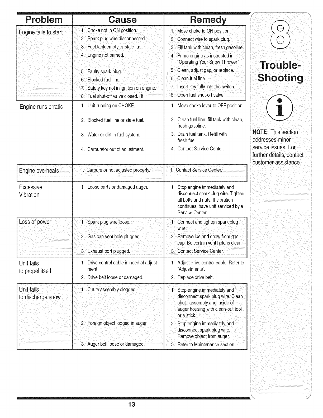
Problem Cause Remedy
Fn_ n_fn _tn _tnd [ 11 ChOkenot inON position: 1 MoveChoketo ON post on
_-= " " "!" "" Spark plugwiredisconnected. 2: Connectwlre to spark plug.
Fue!tankemptyor stalefuel. &Fill tankwithcleanlfreShgaSoiinel
4 Enginenot primed. ,Primeengineas instructedin
op ia,ngYouiSniwTh!o ei
5 FaultySparkplug Clean;adjustgap,or replace:
61Blocked fuel linei 6. Cleanfuel !inel
safetykeynotin ignitiononengine, 7 !nser!keyfu! Yint° ,heswitch:
8. Fue Shut-offva ve c osed.(f 8. Openrue shut-df va re:
Engine runs erratic 1. Movechokeleverto OFFposition.
2. Cleanfuelline; fill tankwithclean,
freshgasoline.
3. Drainfueltank. Refillwith
freshfuel.
4. ContactServiceCenter.
1. Unitrunningon CHOKE.
2. Blockedfuel lineor stalefuel.
3. Wateror dirt in fuelsystem.
4. Carburetorout of adjustment.
Engne overheats 1 Carburetornot adjustedpropery 1 ContactServce Center
Excessive 1. Loosepartsor damagedauger. 1. Stopengineimmediatelyand
Vibration disconnectsparkplugwire.Tighten
all boltsand nuts.Ifvibration
continues,haveunit servicedby a
ServiceCenter.
Loss of power 1, Sparkplugwire loose. 1. Connectandtightensparkplug
wire.
2. Gas capventholeplugged. 2. Removeice andsnowfromgas
I cap.Becertanventholeis clear.
• 3 Exhaustport plugged ". 3 ContactServiceCenter
Unit fails 1. Drivecontrolcane in needof adjust- 1. Adjustdrivecontrolcane. Referto
to propel itself merit. "Adjustments".
2. Drivebelt looseordamaged. 2. Replacedrive belt.
Unit fails 1, Chuteassemblyclogged. 1. Stopengineimmediatelyand
to d scharge snow disconnectsparkplugwire.Clean
chuteassemblyandinsideof
augerhousingwithclean-outtool
ora stick.
2. Foreignobjectlodgedinauger. 2, Stopengineimmediatelyand
disconnectsparkplugwire.
Removeobjectfromauger.
3. Augerbeltlooseor damaged. 3, Referto Maintenancesection
NOTEi ThiSsection
addresses minor
service issues: For
further details,contact
customer assistancel
ii i _iI_ ii
13
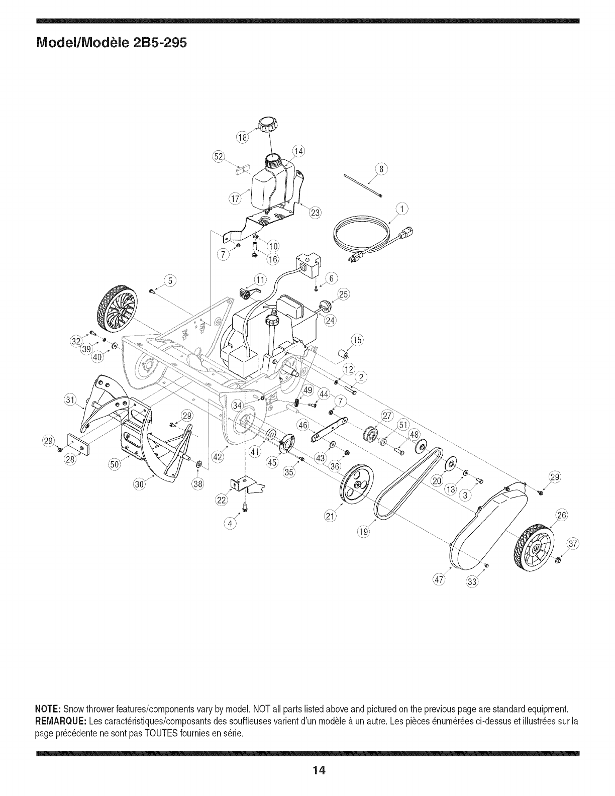
iVlodel/iVlodele 2B5-295
NOTE:Snowthrowerfeatures/componentsvary bymodel.NOTall partslistedaboveand picturedon the previouspageare standardequipment.
REMARQUE:Lescaract_ristiques/composantsdes souffleusesvarientd'un module&unautre.Lespi_ces_num_r_esci-dessuset illustr_essurla
pagepr_c_dentenesontpas TOUTESfourniesen serie.
14
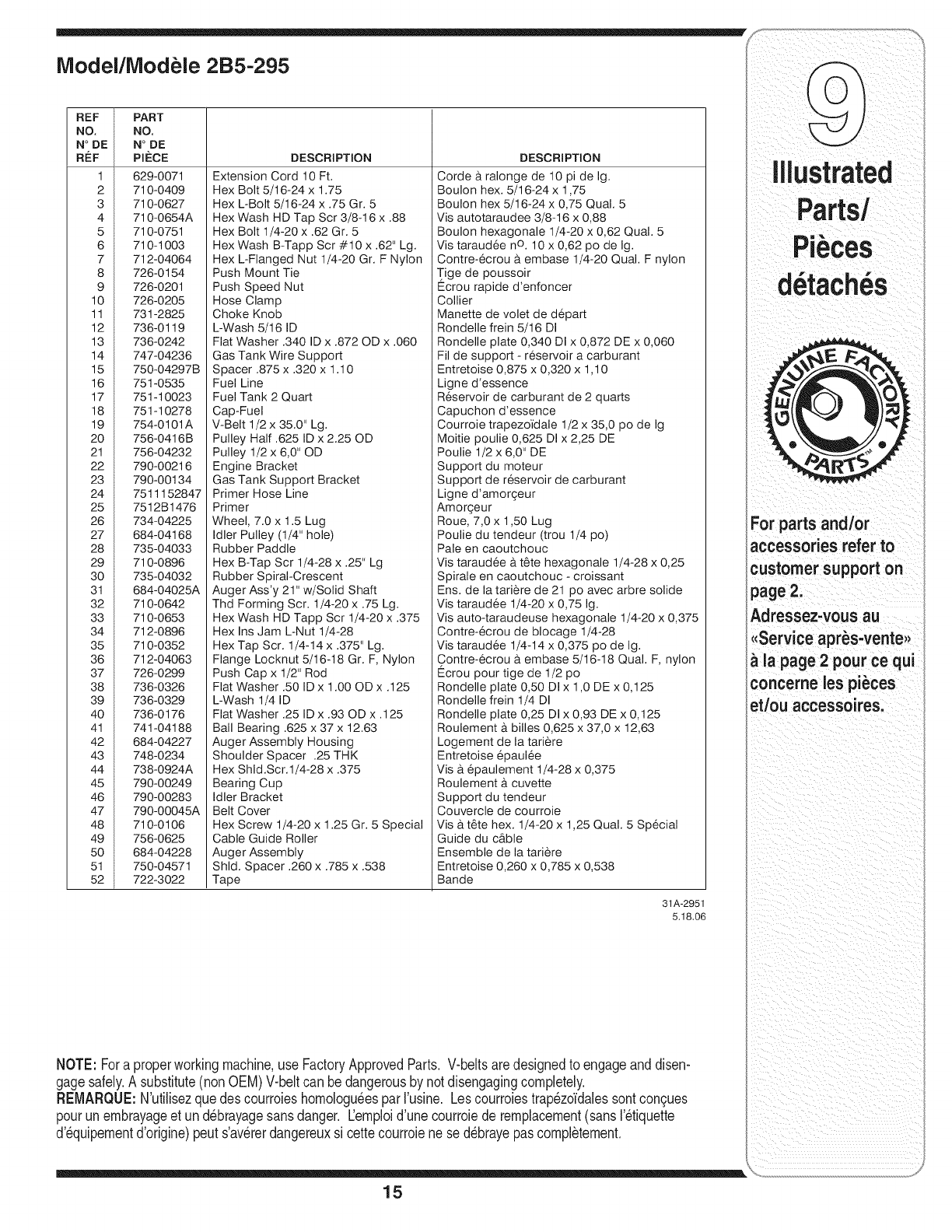
Model/Modele 2B5-295
REF PART
NO, NO,
N° DE N° DE
RI_F PI_:CE
1 629-0071
2 710-0409
3 710-0627
4 710-0654A
5 710-0751
6 710-1003
7 712-04064
8 726-0154
9 726-0201
10 726-0205
11 731-2825
12 736-0119
13 736-0242
14 747-04236
15 750-04297B
16 751-0535
17 751-10023
18 751-10278
19 754-0101A
20 756-0416B
21 756-04232
22 790-00216
23 790-00134
24 7511152847
25 7512B1476
26 734-04225
27 684-04168
28 735-04033
29 710-0896
30 735-04032
31 684-04025A
32 710-0642
33 710-0653
34 712-0896
35 710-0352
36 712-04063
37 726-0299
38 736-0326
39 736-0329
40 736-0176
41 741-04188
42 684-04227
43 748-0234
44 738-0924A
45 790-00249
46 790-00283
47 790-00045A
48 710-0106
49 756-0625
50 684-04228
51 750-04571
52 722-3022
DESCRIPTION
Extension Cord 10 Ft.
Hex Bolt 5/16-24 x 1.75
Hex L-Bolt 5/16-24 x .75 Gr. 5
Hex Wash HD Tap Scr 3/8-16 x .88
Hex Bolt 1/4-20 x .62 Gr. 5
Hex Wash B-Tapp Scr #10 x.62" Lg.
Hex L-Flanged Nut 1/4-20 Gr. F Nylon
Push Mount Tie
Push Speed Nut
Hose Clamp
Choke Knob
L-Wash 5/16 ID
Flat Washer .340 ID x .872 OD x .060
Gas Tank Wire Support
Spacer .875 x.320 x 1.10
Fuel Line
Fuel Tank 2 Quart
Cap-Fuel
V-Belt 1/2 x 35.0" Lg.
Pulley Half .625 ID x 2.25 OD
Pulley 1/2 x 6,0" OD
Engine Bracket
Gas Tank Support Bracket
Primer Hose Line
Primer
Wheel, 7.0 x 1.5 Lug
Idler Pulley (1/4" hole)
Rubber Paddle
Hex B-Tap Scr 1/4-28 x .25" Lg
Rubber Spiral-Crescent
Auger Ass'y 21" w/Solid Shaft
Thd Forming Scr. 1/4-20 x .75 Lg.
Hex Wash HD Tapp Scr 1/4-20 x .375
Hex Ins Jam L-Nut 1/4-28
Hex Tap Scr. 1/4-14 x .375" Lg.
Flange Locknut 5/16-18 Gr. F, Nylon
Push Cap x 1/2" Rod
Flat Washer .50 ID x 1.00 OD x .125
L-Wash 1/4 ID
Flat Washer .25 ID x .93 ODx.125
Ball Bearing .625 x 37 x 12.63
Auger Assembly Housing
Shoulder Spacer .25 THK
Hex Shld.Scr.1/4-28 x .375
Bearing Cup
Idler Bracket
Belt Cover
Hex Screw 1/4-20 x 1.25 Gr. 5 Special
Cable Guide Roller
Auger Assembly
Shld. Spacer .260 x.785 x.538
Tape
DESCRIPTION
Corde a ralonge de 10 pi de Ig.
Boulon hex. 5/16-24 x 1,75
Boulon hex 5/16-24 x 0,75 Qual. 5
Vis autotaraudee 3/8-16 x 0,88
Boulon hexagonale 1/4-20 x 0,62 Qual. 5
Vis taraud6e nO. 10 x 0,62 po de Ig.
Contre-ecrou a embase 1/4-20 Qual. F nylon
Tige de poussoir
Ecrou rapide d'enfoncer
Collier
Manette de volet de d6part
Rondelle frein 5/16 DI
Rondelle plate 0,340 DI x 0,872 DE x 0,060
Fil de support - reservoir a carburant
Entretoise 0,875 x 0,320 x 1,10
Ligne d'essence
R6servoir de carburant de 2 quarts
Capuchon d'essence
Courroie trapezdidale 1/2 x 35,0 po de Ig
Moitie poulie 0,625 DI x 2,25 DE
Poulie 1/2 x 6,0" DE
Support du moteur
Support de reservoir de carburant
Ligne d'amorgeur
Amor_:eur
Roue, 7,0 x 1,50 Lug
Poulie du tendeur (trou 1/4 po)
Pale en caoutchouc
Vis taraud6e a t_te hexagonale 1/4-28 x 0,25
Spirale en caoutchouc - croissant
Ens. de la tariere de 21 po avec arbre solide
Vis taraud6e 1/4-20 x 0,75 Ig.
Vis auto-taraudeuse hexagonale 1/4-20 x 0,375
Contre-6crou de blocage 1/4-28
Vis taraud6e 1/4-14 x 0,375 po de Ig.
Contre-ecrou a embase 5/16-18 Qual. F, nylon
l_crou pour tige de 1/2 po
Rondelle plate 0,50 DI x 1,0 DE x 0,125
Rondelle frein 1/4 DI
Rondelle plate 0,25 DI x 0,93 DE x 0,125
Roulement a billes 0,625 x 37,0 x 12,63
Logement de la tariere
Entretoise epaul6e
Vis a epaulement 1/4-28 x 0,375
Roulement a cuvette
Support du tendeur
Couvercle de courroie
Visa t_te hex. 1/4-20 x 1,25 Qual. 5 Special
Guide du c&ble
Ensemble de la tariere
Entretoise 0,260 x 0,785 x 0,538
Bande
31A-2951
5.18.06
NOTE: Fora properworkingmachine,use FactoryApprovedParts. V-beltsaredesignedto engageanddisen-
gagesafely.A substitute(nonOEM)V-beltcan be dangerousby notdisengagingcompletely.
REMARQUE:N'utilisezquedescourroieshomologu_esparI'usine. Les courroiestrap_zdldalessontcon_ues
pourunembrayageet und_brayagesansdanger. Eemploid'une courroiede remplacement(sansI'_tiquette
d'_quipementd'origine)peuts'avererdangereuxsi cette courroiene sed_brayepascompl_tement.
For parts and/or
accessories refer to
customer support on
page 2.
Adressez-vous au
,,Service apr_s-vente>,
la page 2 pour ce qui
-oncerne les pi_ces
et/ou accessoires.
15
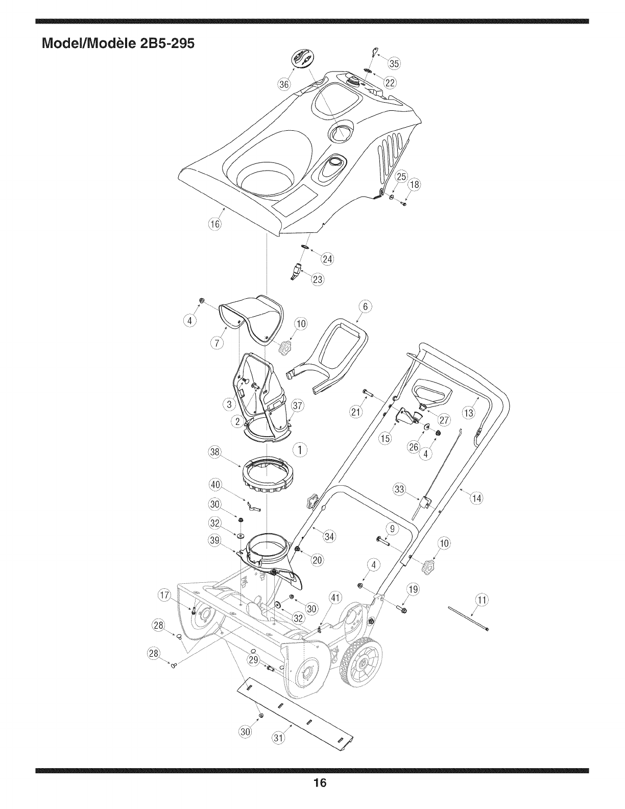
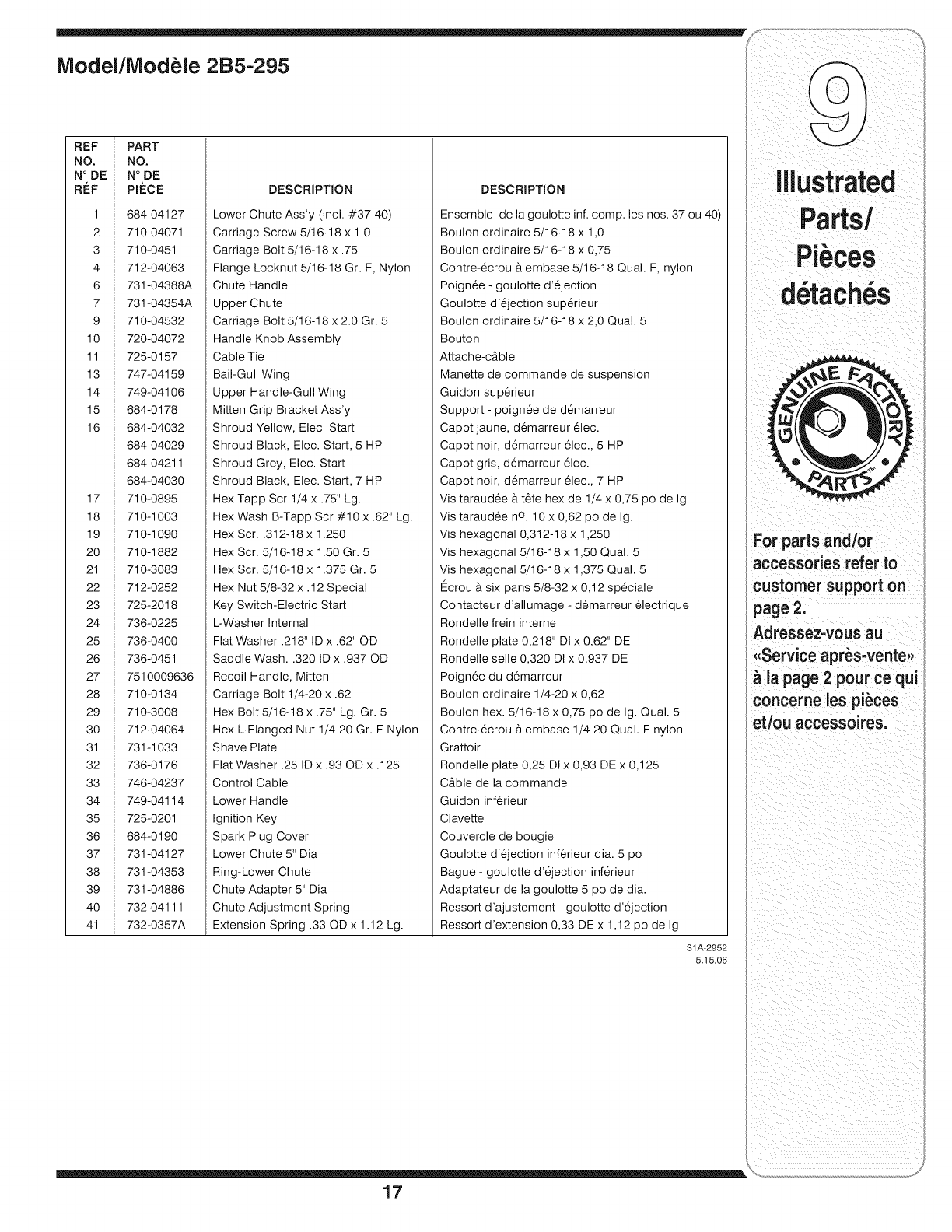
iVlodel/iVlodele 2B5-295
_11)
16
REF PART
NO. NO.
N° DE N° DE
R#:F PIt_CE
1 684-04127
2 710-04071
3 710-0451
4 712-04063
6 731-04388A
7 731-04354A
9 710-04532
10 720-04072
11 725-0157
13 747-04159
14 749-04106
15 684-0178
16 684-04032
684-04029
684-04211
684-04030
17 710-0895
18 710-1003
19 710-1090
20 710-1882
21 710-3083
22 712-0252
23 725-2018
24 736-0225
25 736-0400
26 736-0451
27 7510009636
28 710-0134
29 710-3008
30 712-04064
31 731-1033
32 736-0176
33 746-04237
34 749-04114
35 725-0201
36 684-0190
37 731-04127
38 731-04353
39 731-04886
40 732-04111
41 732-0357A
DESCRIPTION
Lower Chute Ass'y (Incl. #37-40)
Carriage Screw 5/16-18 x 1.0
Carriage Bolt 5/16-18 x .75
Flange Locknut 5/16-18 Gr. F, Nylon
Chute Handle
Upper Chute
Carriage Bolt 5/16-18 x 2.0 Gr. 5
Handle Knob Assembly
Cable Tie
Bail-Gull Wing
Upper Handle-Gull Wing
Mitten Grip Bracket Ass'y
Shroud Yellow, Elec. Start
Shroud Black, Elec. Start, 5 HP
Shroud Grey, Elec. Start
Shroud Black, Elec. Start, 7 HP
Hex Tapp Scr 1/4 x .75" Lg.
Hex Wash B-Tapp Scr #10 x .62" Lg.
Hex Scr..312-18 x 1.250
Hex Scr. 5/16-18 x 1.50 Gr. 5
Hex Scr. 5/16-18 x 1.375 Gr. 5
Hex Nut 5/8-32 x. 12 Special
Key Switch-Electric Start
L-Washer Internal
Flat Washer .218" ID x .62" OD
Saddle Wash..320 ID x .937 OD
Recoil Handle, Mitten
Carriage Bolt 1/4-20 x .62
Hex Bolt 5/16-18 x .75" Lg. Gr. 5
Hex L-Flanged Nut 1/4-20 Gr. F Nylon
Shave Plate
Flat Washer .25 ID x .93 OD x .125
Control Cable
Lower Handle
Ignition Key
Spark Plug Cover
Lower Chute 5" Dia
Ring-Lower Chute
Chute Adapter 5" Dia
Chute Adjustment Spring
Extension Spring .33 OD x 1.12 Lg.
DESCRIPTION
Ensemble de la goulotte inf. comp. les nos. 37 ou 40)
Boulon ordinaire 5/16-18 x 1,0
Boulon ordinaire 5/16-18 x 0,75
Contre-6crou & embase 5/16-18 Qual. F, nylon
Poign6e - goulotte d'6jection
Goulotte d'6jection sup_rieur
Boulon ordinaire 5/16-18 x 2,0 Qual. 5
Bouton
Attache-cAble
Manette de commande de suspension
Guidon sup6rieur
Support - poign6e de d6marreur
Capot jaune, demarreur 61ec.
Capot noir, demarreur 61ec., 5 HP
Capot gris, demarreur 61ec.
Capot noir, demarreur 61ec., 7 HP
Vis taraud6e & t6te hex de 1/4 x 0,75 po de Ig
Vis taraudee no. 10 x 0,62 po de Ig.
Vis hexagonal 0,312-18 x 1,250
Vis hexagonal 5/16-18 x 1,50 Qual. 5
Vis hexagonal 5/16-18 x 1,375 Qual. 5
Ecrou & six pans 5/8-32 x 0,12 sp_ciale
Contacteur d'allumage - d6marreur 61ectrique
Rondelle frein interne
Rondelle plate 0,218" Dt x 0,62" DE
Rondelle selle 0,320 DI x 0,937 DE
Poign6e du demarreur
Boulon ordinaire 1/4-20 x 0,62
Boulon hex. 5/16-18 x 0,75 po de Ig. Qual. 5
Contre-6crou & embase 1/4-20 Qual. F nylon
Grattoir
Rondelle plate 0,25 DIx 0,93 DE x 0,125
CAble de la commande
Guidon inf6rieur
Clavette
Couvercle de bougie
Goulotte d'6jection inf_rieur dia. 5 po
Bague - goulotte d'ejection inf_rieur
Adaptateur de la goulotte 5 po de dia.
Ressort d'ajustement - goulotte d'6jection
Ressort d'extension 0,33 DE x 1,12 po de Ig
31A-2952
5.15.06
For parts and/or
accessories refer to
customer support on
page 2.
Adressez-vous au
<<Serviceapr_s-vente_,
& la page 2 pour ce qui
concerne les pi_ces
et/ou accessoires.
17

MANUFACTURER'S LiMiTED WARRANTY
The limitedwarrantysetforthbelowisgivenby MTDLLCwithrespect
to newmerchandisepurchasedandusedin the UnitedStatesand/or its
territoriesandpossessions,andby MTDProductsLimitedwithrespectto
newmerchandisepurchasedandusedin Canadaand/or itsterritoriesand
possessions(eitherentity respectively,"MTD").
MTDwarrantsthisproduct(excludingitsnormalwearpartsas described
below)againstdefectsinmaterialandworkmanshipfor a periodof two
(2) yearscommencingon thedate of originalpurchaseandwill,at its
option,repairor replace,free of charge,any partfoundto be defective
inmaterialsor workmanship.Thislimitedwarrantyshallonly applyif
thisproducthas beenoperatedand maintainedinaccordancewiththe
Operator'sManualfurnishedwiththe product,and hasnot beensubjectto
misuse,abuse,commercialuse,neglect,accident,impropermaintenance,
alteration,vandalism,theft,fire,water,or damagebecauseof other perilor
naturaldisaster.Damageresultingfromthe installationor use of anypart,
accessoryorattachmentnotapprovedby MTDfor usewiththe product(s)
coveredby thismanualwillvoid yourwarrantyas to any resultingdamage.
Normalwearpartsarewarrantedto befree fromdefectsinmaterialand
workmanshipfor a periodof thirty (30)daysfromthedateof purchase.
Normalwearpartsinclude,butare notlimitedto itemssuchas: batteries,
belts,blades,bladeadapters,grassbags,riderdeckwheels,seats,snow
throwerskidshoes,frictionwheels,shaveplates,augerspiral rubberand
tires.
NOWTO OBTAINSERVICE:Warrantyserviceis available,WITH
PROOFOF PURCHASE,throughyour localauthorizedservicedealer.To
locatethe dealerin yourarea;
In the U.S.A.:
Checkyour YellowPages,or contactMTD LLCat RO.Box361131,
Cleveland,Ohio44136-0019,orcall 1-800-800-7310or 1-330-220-4683
or logonto ourWeb siteat www.mtdproducts.com.
In Canada:
ContactMTDProductsLimited,Kitchener,ON N2G4J1,or call 1-800-
668-1238or logon to ourWebsiteat www.mtdcanada.com.
Thislimitedwarrantydoesnot providecoveragein the followingcases:
a. Theengineor componentpartsthereof.Theseitemsmaycarrya
separatemanufacturer'swarranty.Referto applicablemanufacturer's
warrantyfor termsand conditions.
b. Logsplitterpumps,valves,andcylindershavea separateone-year
warranty.
c. Routinemaintenanceitemssuchas lubricants,filters,blade
sharpening,tune-ups,brakeadjustments,clutchadjustments,deck
adjustments,andnormaldeteriorationof the exteriorfinishdueto use
orexposure.
d. Servicecompletedby someoneotherthan an authorizedservice
dealer.
e. MTDdoes notextendany warrantyfor productssoldor exported
outsideof the UnitedStatesand/or Canada,andtheir respectivepos-
sessionsandterritories,exceptthosesoldthroughMTD'sauthorized
channelsof exportdistribution.
f. Replacementpartsthatarenot genuineMTDparts.
g. Transportationchargesand servicecalls.
h. If Productsare usedcommercially.(MTD mayseparatelyoffer Limited
CommercialWarrantiesoncertainselectproducts.Askyourdealeror
retailerfor detailsorcontactMTDServicefor moreinformation.)
No impliedwarranty, includingany impliedwarranty of merchant-
ability of fitness for a particularpurpose,applies after the applicable
periodof express written warranty above as to the partsas identi-
fied. No other express warranty, whether written or oral, except as
mentionedabove,given by any personor entity,includingadealer
or retailer,with respect to any product,shallbind MTD.Duringthe
periodof the warranty, the exclusiveremedyis repairor replacement
of the productas setforth above.
The provisionsas setforth inthis warranty providethe soleand
exclusiveremedyarising from the sale.MTDshallnot be liable
for incidentalor consequentiallossor damage including,without
limitation, expensesincurredfor substituteor replacement lawncare
servicesor for rentalexpenses to temporarily replacea warranted
product.
Somejurisdictionsdo notallowthe exclusionorlimitationof incidentalor
consequentialdamages,or limitationson howlonganimpliedwarranty
lasts,so the aboveexclusionsor limitationsmaynotapplyto you.
In noeventshall recoveryof any kind begreaterthan theamountof the
purchasepriceof the productsold.Alterationof safety features of the
productshall void this warranty. Youassumethe riskandliabilityfor
loss, damage,or injuryto youandyour propertyand/orto othersandtheir
propertyarisingout of the misuseor inabilityto use theproduct.
Thislimitedwarrantyshall notextendto anyoneotherthanthe original
purchaseror to the personfor whomitwaspurchasedas a gift.
HOWLOCALLAWSRELATETO THiS WARRANTY:Thislimitedwar-
rantygivesyou specificlegalrights,andyou mayalso haveother rights
thatvary indifferentjurisdictions.
IMPORTANT:OwnermustpresentOriginalProofof Purchaseto obtain
warrantycoverage.
iVlTDLLC, RO. BOX 361131CLEVELAND, OHiO 44136-0019; Phone: 1-800-800-7310
iVlTDProducts Ltd., P. O. BOX 1386, KITCHENER, ON N2G 4J1; Phone: 1-800-668-1238
18
