MTI 6220APU-ABG WLAN CATV Access Point User Manual 2
MTI Co., Ltd. WLAN CATV Access Point 2
UserManual.wiki
>
MTI
>
6220APU-ABG User Manual
>
User Manual 2
Contents
1.
User Manual 1
2.
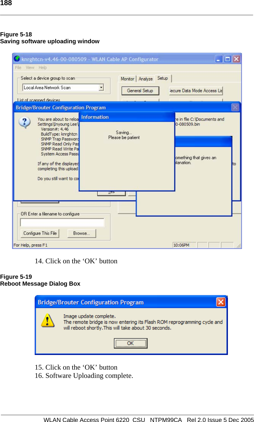
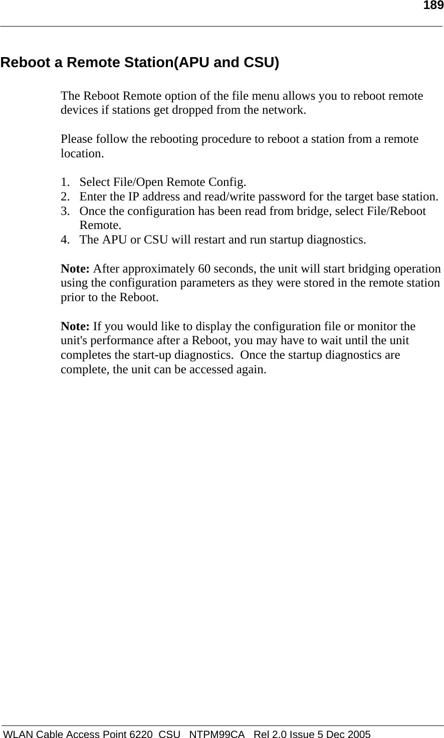
User Manual 2
User Manual 2
Navigation menu
Upload a User Manual
Namespaces
Wiki Guide
HTML
PDF
Info
Views
User Manual
Discussion / Help
Navigation
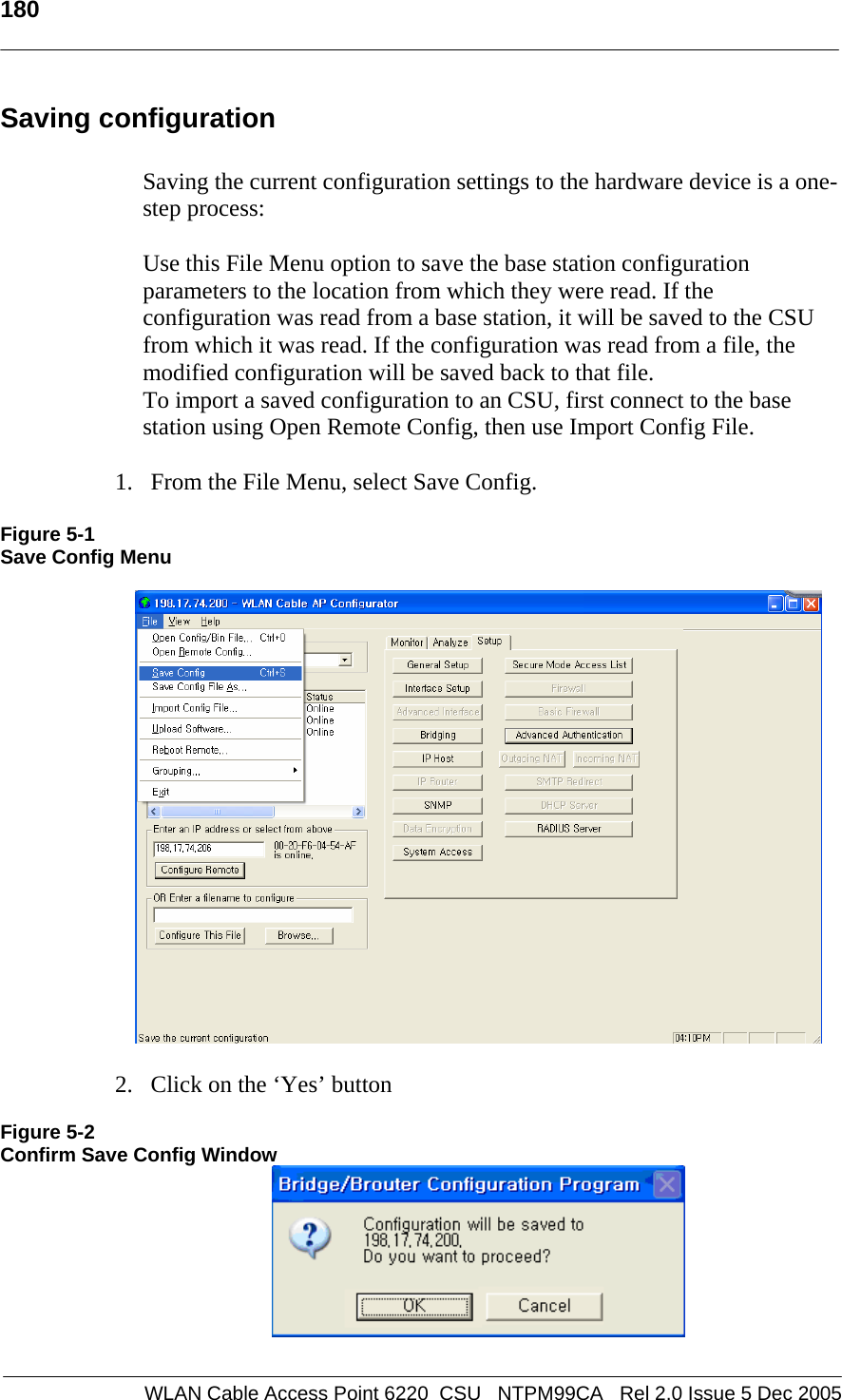
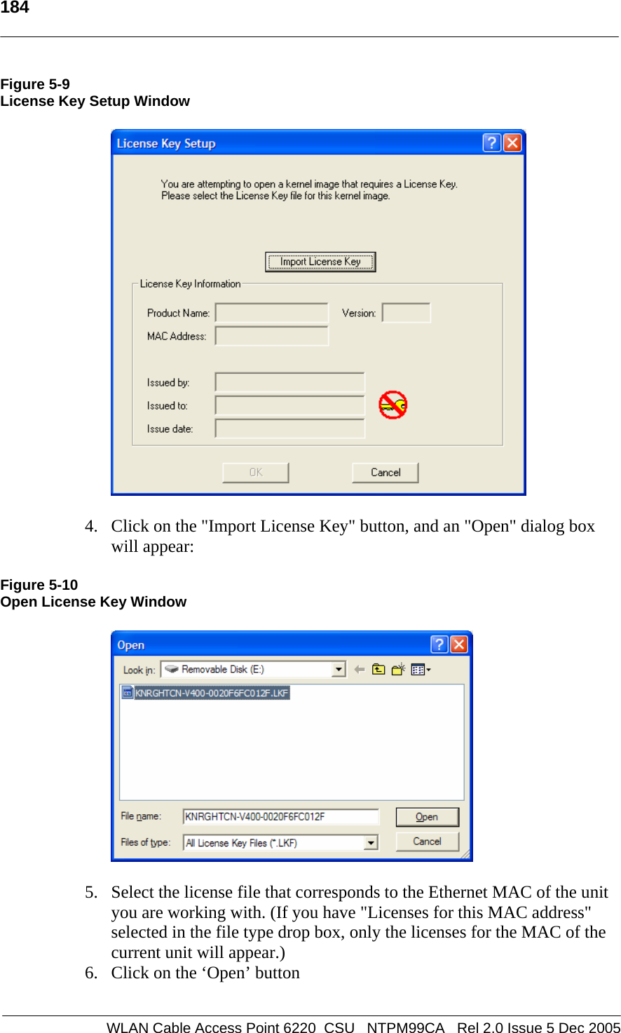
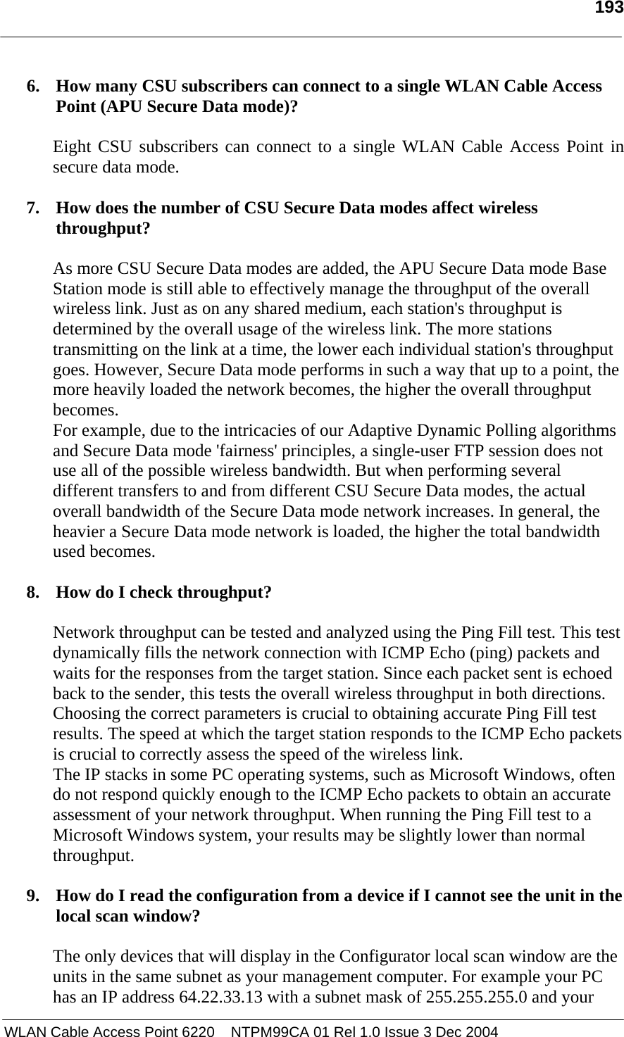
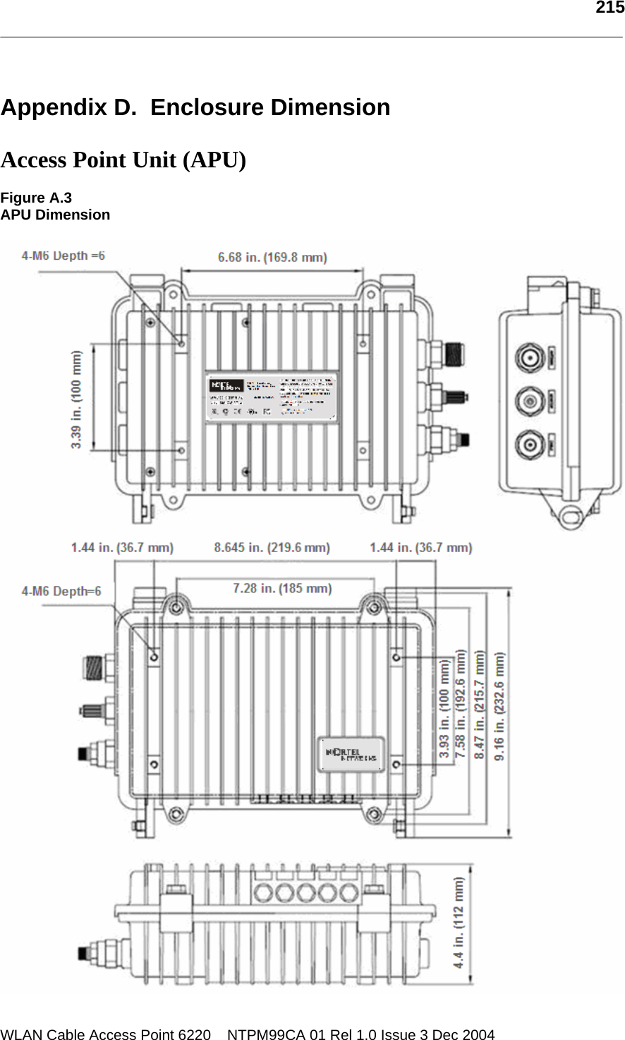
![198 WLAN Cable Access Point 6220 NTPM99CA 01 Rel 1.0 Issue 3 Dec 2004 Appendix A. Specification Access Point Unit (APU) Physical Dimension z 300(W) * 232.6(L) * 112(D) [Unit: mm] z 11.81 (W) * 9.157 (L) * 4.40 (D) [Unit: inch] Weight(without antenna): 6.9234 lbs(<7 lbs), 3.14 Kg Enclosure: Strong Aluminum alloyed –Steel with anodizing coating surface(Waterproof, EMI protection, Vibration Robust) Power consumption: Max 12W(65Vac/180mA) System elements: Access Point, Cable Modem, HFC Signal Filter, Power Supply Unit Interface Ports: Coaxial Port, Monitoring Port, Antenna Port (N-type) Strand mountable and Antenna included Wireless LAN Wireless LAN standard: IEEE 802.11a/b/g Frequency Band & Channel 2.4~2.4835GHz(ISM), 5.725 ~ 5.825GHz (U-NII Upper band) 802.11a(U-NII) Frequency Channel 149 5745 MHz 153 5765 MHz 157 5785 MHz 161 5805 MHz 802.11b/g(ISM) Frequency Channel 6 2437 MHz1 2412 MHz 7 2442 MHz2 2417 MHz 8 2447 MHz3 2422 MHz 9 2452 MHz4 2427 MHz 10 2457 MHz5 2432 MHz 11 2462 MHz Modulation: DSSS(DBPSK,DQPSK,CCK), OFDM(16QAM, QPSK,BPSK) Data rate: 1Mbps, 2Mbps, 5.5Mbps, 11Mbps, 6Mbps, 9Mbps, 12Mbps, 18Mbps, 24Mbps, 36Mbps, 48Mbps, 54Mbps Power adjustment (4 steps): 100%(Max), 50%, 25%, 12.5%](https://usermanual.wiki/MTI/6220APU-ABG.User-Manual-2/User-Guide-621756-Page-17.png)
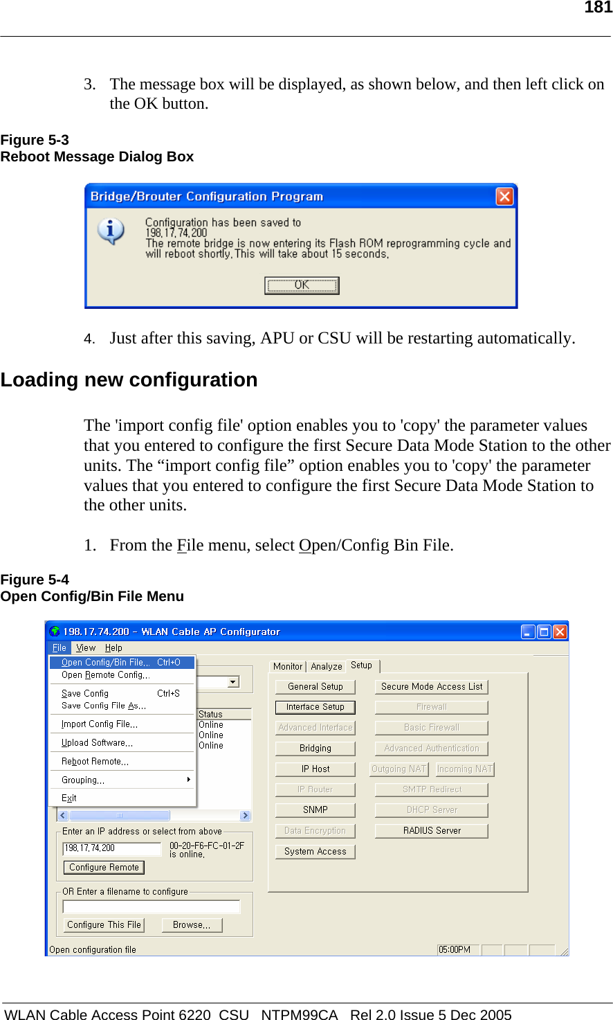
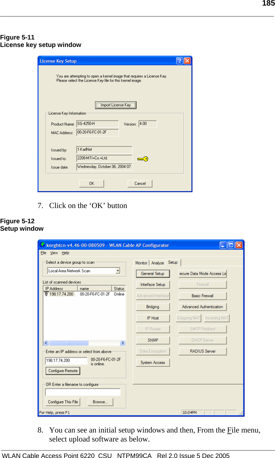
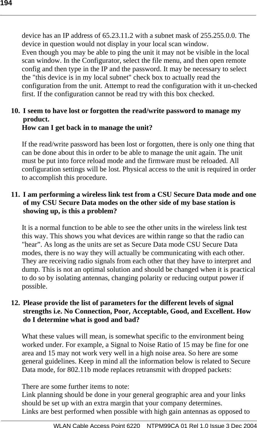
![199 WLAN Cable Access Point 6220 NTPM99CA 01 Rel 1.0 Issue 3 Dec 2004 Maximum Transmit Power(Radio) Output power table [dBm] in 802.11a CH 5745MHz 5765MHz 5785MHz 5805MHz remark 6~24 Mbps 11.6 12.1 11.8 12.0 +/-1.5dB 36 Mbps 11.3 11.6 11.4 11.6 +/-1.5dB 48 Mbps 11.2 11.5 11.2 11.5 +/-1.5dB 54Mbps 10.6 10.8 10.2 10.6 +/-1.5dB Output power table [dBm] in 802.11g CH 2412 MHz 2447MHz 2462 MHz remark 6~24 Mbps 3 13.2 2.3 +/-1.5dB36 Mbps 2.6 12.8 1.8 +/-1.5dB48 Mbps 2.3 12.6 1.8 +/-1.5dB54Mbps 2.3 12.6 1.7 +/-1.5dB Output power table [dBm] in 802.11b CH 2412 MHz 2447MHz 2462 MHz remark 1 Mbps 8 13 7.7 +/-1.5dB2 Mbps 8 13 7.7 +/-1.5dB5.5 Mbps 8 13 7.4 +/-1.5dB11 Mbps 8 13 7.2 +/-1.5dB Max EIRP [dBm] for PMP topology - 802.11a with 22dBi antenna (NTA-5807): 34.1 dBm - 802.11g/b Mode NTA-2407 NTA-2412 NTA-2400 EIRP Limit 11g 27.2 22.2 20.2 36 dBm(4W) 11b 27 21 20 36 dBm(4W) Note: Unlike 802.11b (DSSS), in case of 802.11g (OFDM), it’s been calibrated to transmit much less output power than 802.11b because the transmit power at both edge channels is restricted by FCC rules. Receive sensitivity: Min. -71dBm at 54Mbps / Min -88dBm at 11Mbps Cable modem [Receiver/Downstream]](https://usermanual.wiki/MTI/6220APU-ABG.User-Manual-2/User-Guide-621756-Page-18.png)
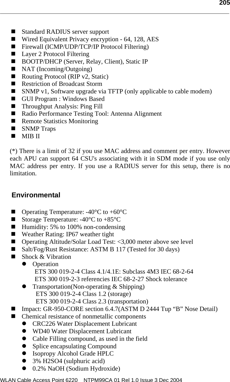
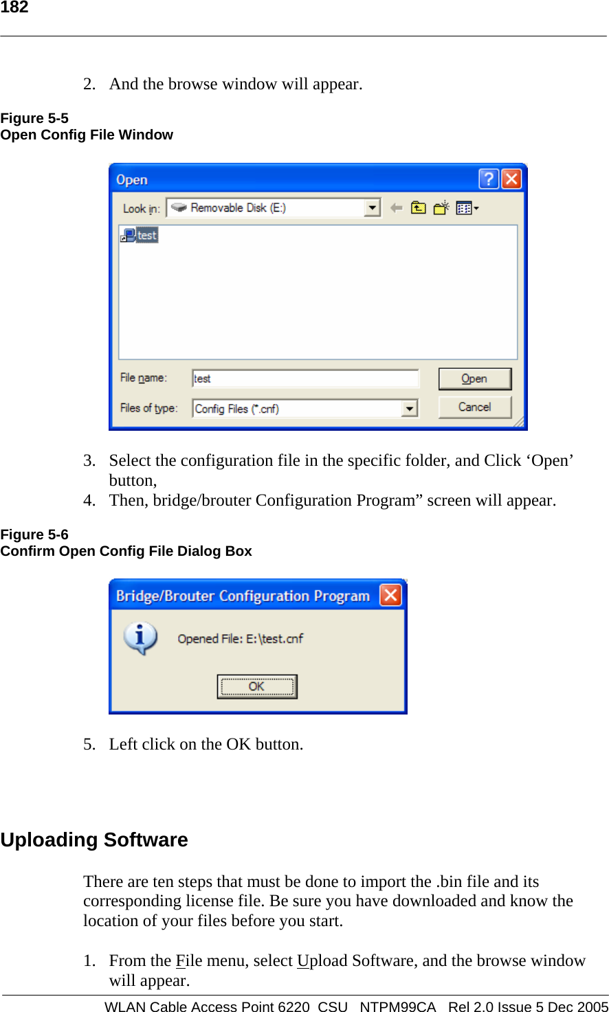
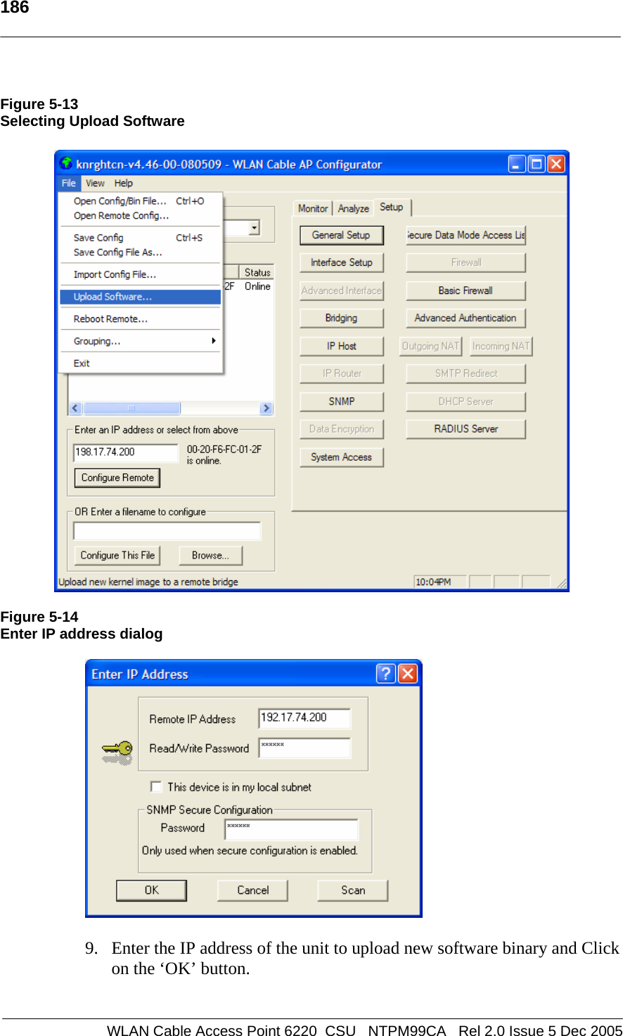
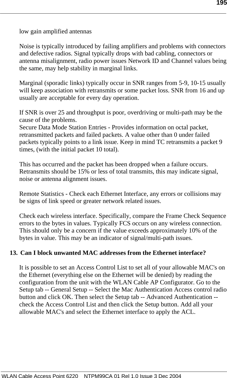
![200 WLAN Cable Access Point 6220 NTPM99CA 01 Rel 1.0 Issue 3 Dec 2004 Downstream Modulation: 64/256 QAM Symbol Rate: 5.056941Msym/sec(64QAM), 5.360537Msym/sec (265QAM) Frequency Range: 88-860 MHz Channel Width : 6MHz Maximum Downstream Data Rate: 27/38 Mbps {64QAM/256QAM} RF Input Sensitivity: A. Cable modem only : -21 to +21dBmV B. Cable Modem + HFC Filter: -15 to +15dBmV 64 QAM Performance @ 23 dB Es/No: BER < 10E-8 Input Impedance: 75 Ohm [Transmitter/Upstream] Frequency Range: 5-42 MHz Bandwidth A-TDMA : 200,400,800.1600,3200,6400KHz S-CDMA : 1600,3200,6400KHz Upstream Modulation: QPSK/16QAM, 32QAM/64QAM(A-TDMA), 128QAM(S-CDMA) Encoding: Reed-Solomon (RS), Trellis Coded Modulation (TCM) Max Data Rate: 30.72 Mbps(DOCSIS 2.0) RF Output Level: -2 to +60 dBmV Output Power Level A-TDMA : +5 ~ +61dBmV (32QAM,64QAM) +5 ~ +61dBmV(8QAM,16QAM) +5 ~ +62dBmV(QPSK) S-CDMA : +6 ~ +55dBmV(All modulation) Gain Control Range: 63dB Frequency Stability: ± 5 kHz Output Impedance: 75 Ohms Software Firmware : APU Secure Data Mode (Base Station) Wireless Service Protocol : Secure Data Mode, Dynamic Polling MAC access control – 32 local MAC Address Table (SDM mode)* Standard RADIUS server support Wired Equivalent Privacy encryption - 64, 128, AES Firewall (ICMP/UDP/TCP/IP Protocol Filtering) Layer 2 Protocol Filtering BOOTP/DHCP (Server, Relay, Client), Static IP NAT (Incoming/Outgoing) Routing Protocol (RIP v2, Static)](https://usermanual.wiki/MTI/6220APU-ABG.User-Manual-2/User-Guide-621756-Page-19.png)
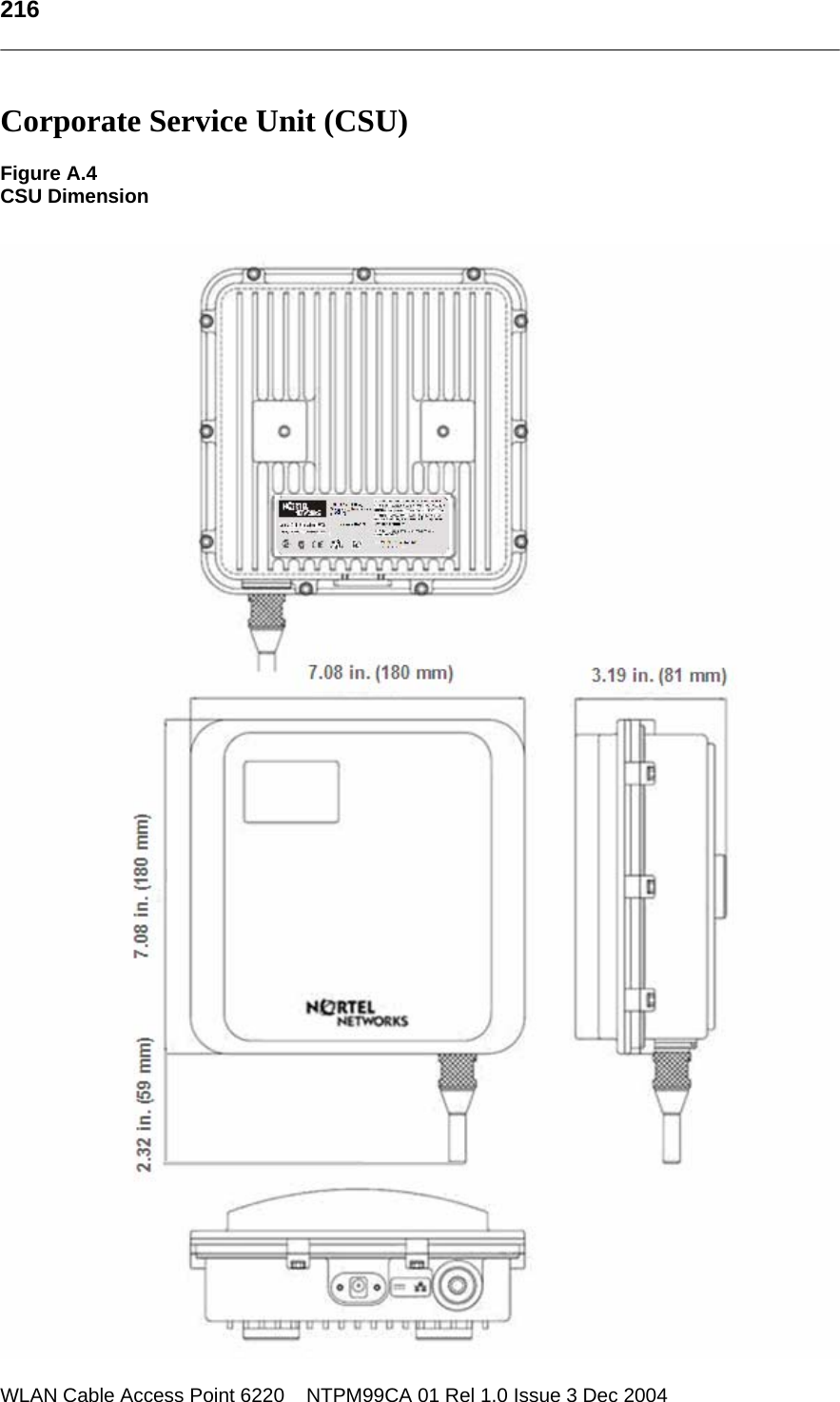
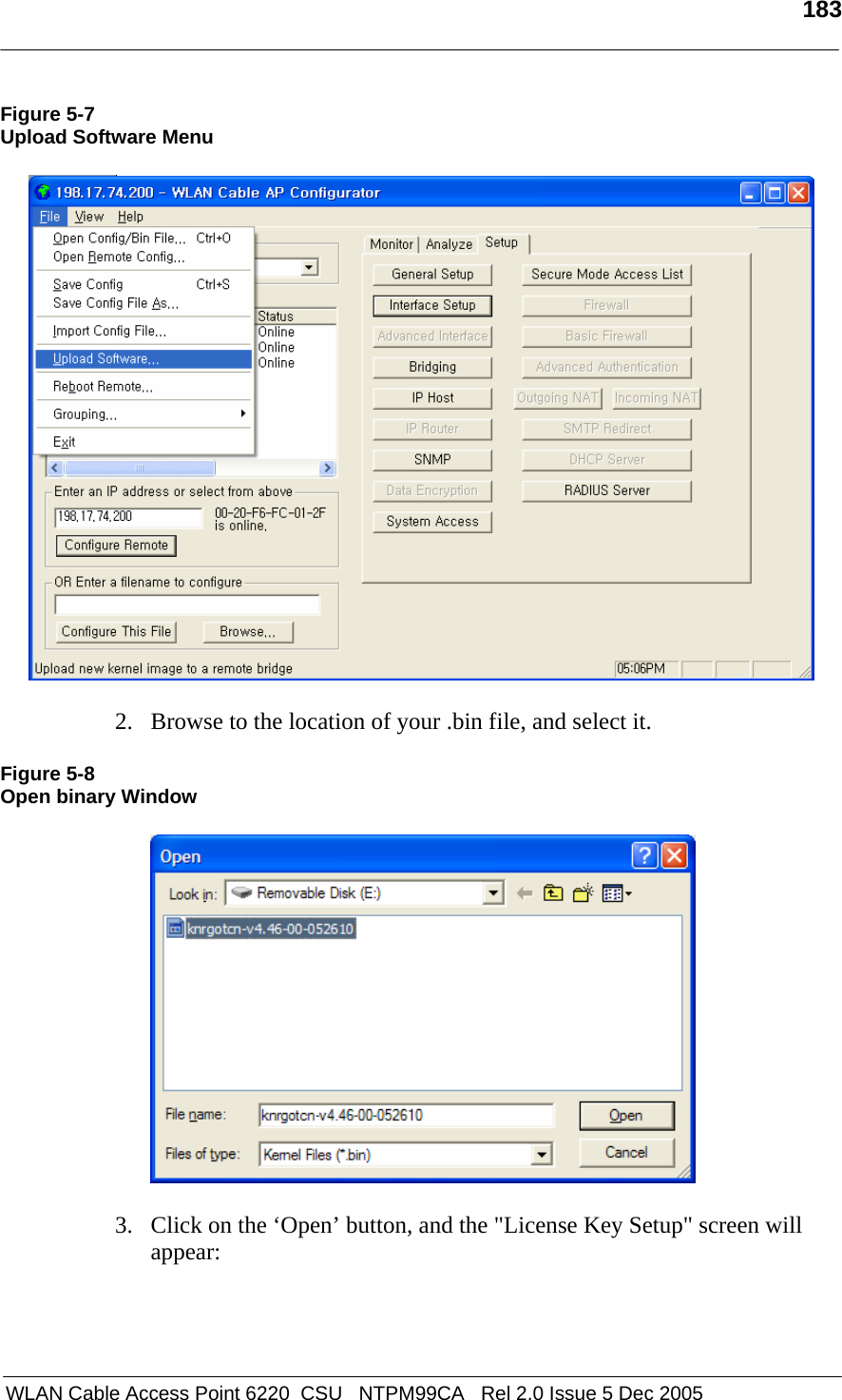
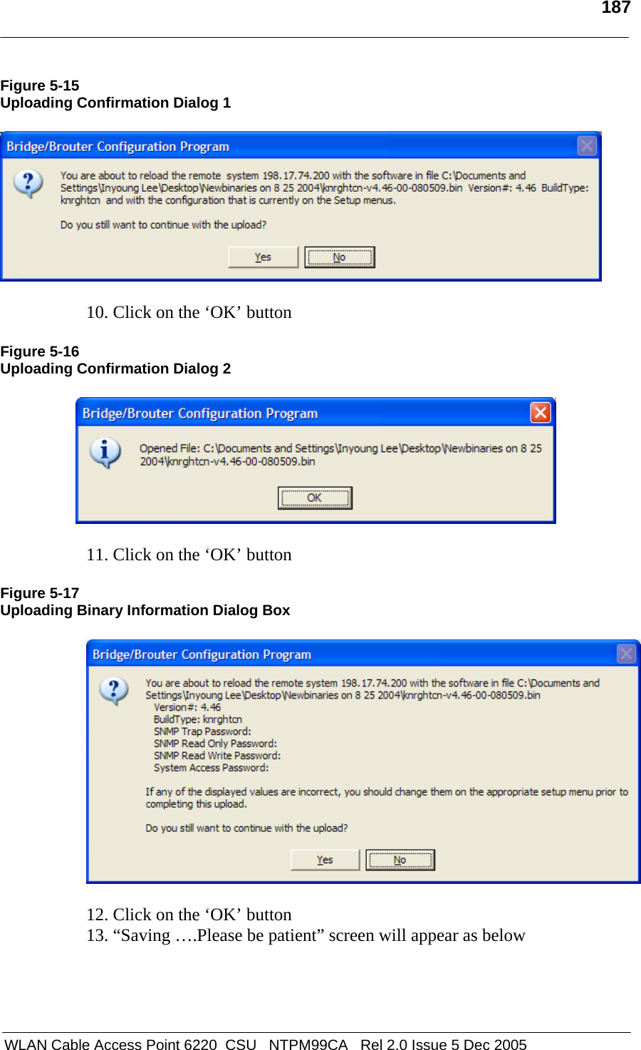
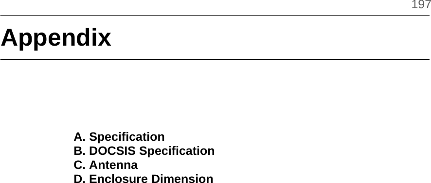
![203 WLAN Cable Access Point 6220 NTPM99CA 01 Rel 1.0 Issue 3 Dec 2004 Corporate Service Unit (CSU) Physical Dimension 180(W) * 180(L) *81(D) [Unit: mm] 180(W) * 239(L) *81(D) with the EMI cap [Unit:inch] Weight(without antenna): 2.8659 lbs(1.30 Kg) with the mounting bracket kit Enclosure: Gray UV Stabilized ASA(Cover), Aluminum and HDG Steel(Body) Power consumption: Max 6W(3.3Vdc/1.5A) System elements: Access Point, POE PD(Power Device) Interface Ports: Ethernet Port(CAT5/POE/802.3af) Pole mountable and Built-in type Antenna Pole mountable and Built-in type Antenna Wireless LAN Wireless LAN standard: IEEE 802.11a/b/g Frequency Band & Channel 2.4~2.4835GHz(ISM), 5.725 ~ 5.825GHz (U-NII Upper band) 802.11a(U-NII) Frequency Channel 149 5745 MHz 153 5765 MHz 157 5785 MHz 161 5805 MHz 802.11b/g(ISM) Frequency Channel 6 2437 MHz1 2412 MHz 7 2442 MHz2 2417 MHz 8 2447 MHz3 2422 MHz 9 2452 MHz4 2427 MHz 10 2457 MHz5 2432 MHz 11 2462 MHz Modulation: DSSS(DBPSK,DQPSK,CCK), OFDM(16QAM, QPSK,BPSK) Data rate: 1Mbps, 2Mbps, 5.5Mbps, 11Mbps, 6Mbps, 9Mbps, 12Mbps, 18Mbps, 24Mbps, 36Mbps, 48Mbps, 54Mbps Power adjustment (4 steps): 100%(Max), 50%, 25%, 12.5%](https://usermanual.wiki/MTI/6220APU-ABG.User-Manual-2/User-Guide-621756-Page-22.png)
![204 WLAN Cable Access Point 6220 NTPM99CA 01 Rel 1.0 Issue 3 Dec 2004 Maximum Transmit Power(Radio) Output power table [dBm] in 802.11a CH 5745MHz 5765MHz 5785MHz 5805MHz remark 6~24 Mbps 11.6 12.1 11.8 12.0 +/-1.5dB 36 Mbps 11.3 11.6 11.4 11.6 +/-1.5dB 48 Mbps 11.2 11.5 11.2 11.5 +/-1.5dB 54Mbps 10.6 10.8 10.2 10.6 +/-1.5dB Output power table [dBm] in 802.11g CH 2412 MHz 2447MHz 2462 MHz remark 6~24 Mbps 3 13.2 2.3 +/-1.5dB36 Mbps 2.6 12.8 1.8 +/-1.5dB48 Mbps 2.3 12.6 1.8 +/-1.5dB54Mbps 2.3 12.6 1.7 +/-1.5dB Output power table [dBm] in 802.11b CH 2412 MHz 2447MHz 2462 MHz remark 1 Mbps 8 13 7.7 +/-1.5dB2 Mbps 8 13 7.7 +/-1.5dB5.5 Mbps 8 13 7.4 +/-1.5dB11 Mbps 8 13 7.2 +/-1.5dB Max EIRP [dBm] for PMP topology - 802.11a with 22dBi antenna (NTA-5807): 34.1 dBm - 802.11g/b Mode NTA-2407 NTA-2412 NTA-2400 EIRP Limit 11g 27.2 22.2 20.2 36 dBm(4W) 11b 27 21 20 36 dBm(4W) Note: Unlike 802.11b (DSSS), in case of 802.11g (OFDM), it’s been calibrated to transmit much less output power than 802.11b because the transmit power at both edge channels is restricted by FCC rules. Receive sensitivity: Min. -71dBm at 54Mbps / Min -88dBm at 11Mbps Software Firmware : APU CSU Secure Data Mode (Base Station) Wireless Service Protocol : Secure Data Mode MAC access control – 32 local MAC Address Table (SDM mode)*](https://usermanual.wiki/MTI/6220APU-ABG.User-Manual-2/User-Guide-621756-Page-23.png)