Contents
- 1. User Manual 1
- 2. User Manual 2
User Manual 2
180
WLAN Cable Access Point 6220 CSU NTPM99CA Rel 2.0 Issue 5 Dec 2005
Saving configuration
Saving the current configuration settings to the hardware device is a one-
step process:
Use this File Menu option to save the base station configuration
parameters to the location from which they were read. If the
configuration was read from a base station, it will be saved to the CSU
from which it was read. If the configuration was read from a file, the
modified configuration will be saved back to that file.
To import a saved configuration to an CSU, first connect to the base
station using Open Remote Config, then use Import Config File.
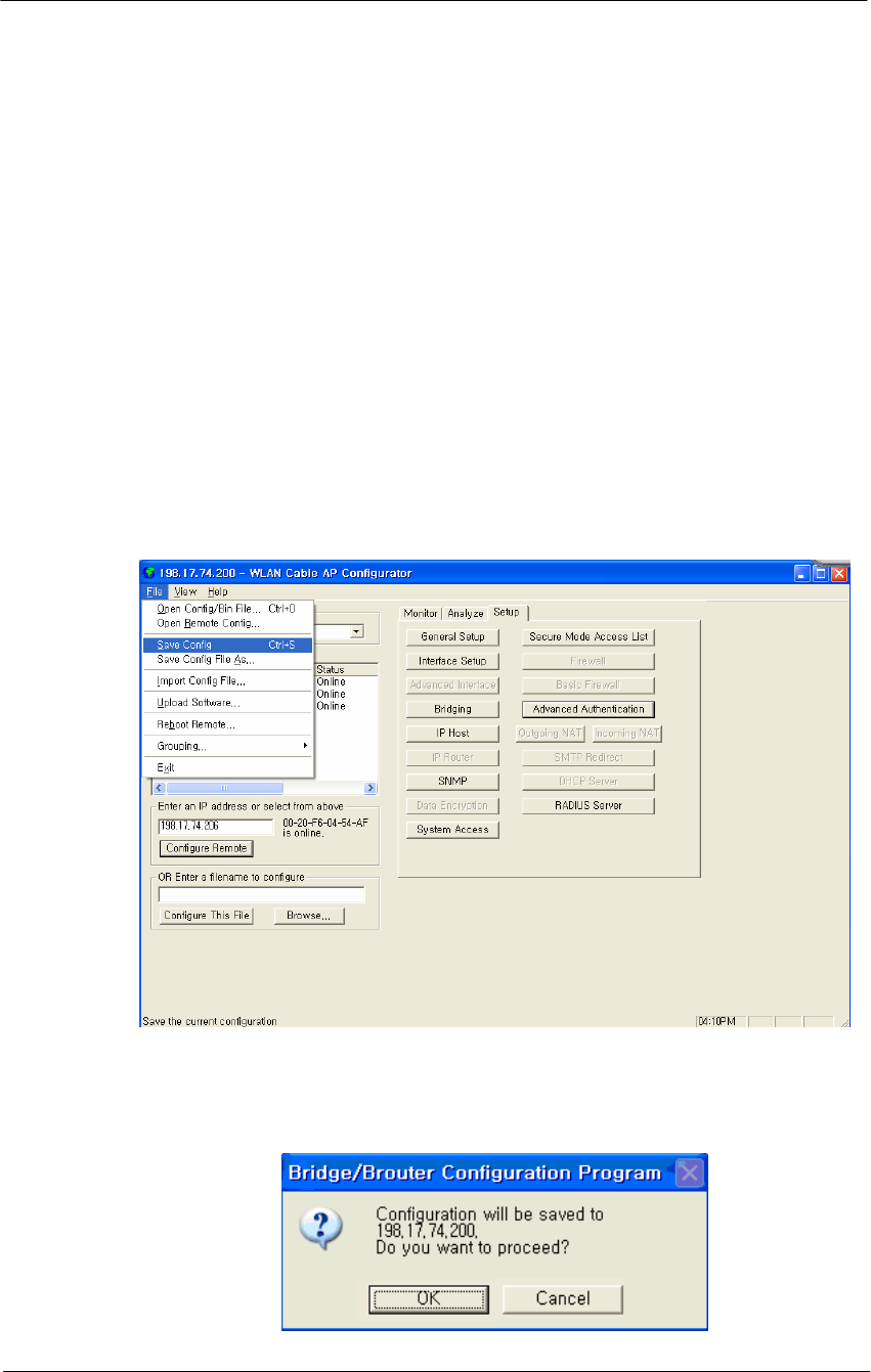
1. From the File Menu, select Save Config.
Figure 5-1
Save Config Menu
2. Click on the ‘Yes’ button
Figure 5-2
Confirm Save Config Window
181
WLAN Cable Access Point 6220 CSU NTPM99CA Rel 2.0 Issue 5 Dec 2005
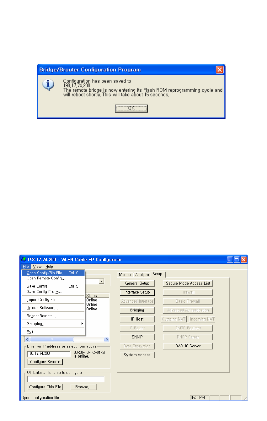
3. The message box will be displayed, as shown below, and then left click on
the OK button.
Figure 5-3
Reboot Message Dialog Box
4. Just after this saving, APU or CSU will be restarting automatically.
Loading new configuration
The 'import config file' option enables you to 'copy' the parameter values
that you entered to configure the first Secure Data Mode Station to the other
units. The “import config file” option enables you to 'copy' the parameter
values that you entered to configure the first Secure Data Mode Station to
the other units.
1. From the File menu, select Open/Config Bin File.
Figure 5-4
Open Config/Bin File Menu
182
WLAN Cable Access Point 6220 CSU NTPM99CA Rel 2.0 Issue 5 Dec 2005
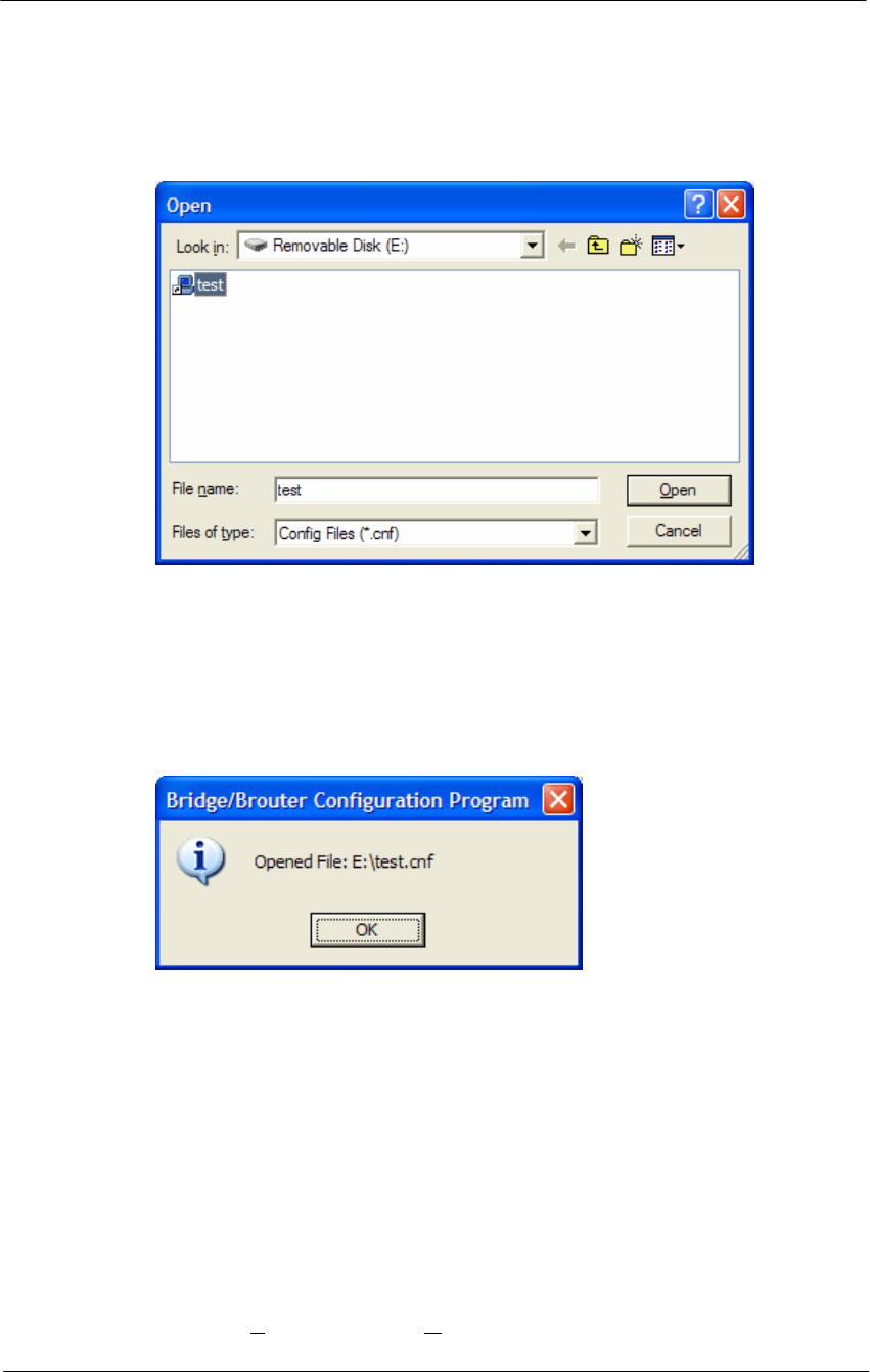
2. And the browse window will appear.
Figure 5-5
Open Config File Window
3. Select the configuration file in the specific folder, and Click ‘Open’
button,
4. Then, bridge/brouter Configuration Program” screen will appear.
Figure 5-6
Confirm Open Config File Dialog Box
5. Left click on the OK button.
Uploading Software
There are ten steps that must be done to import the .bin file and its
corresponding license file. Be sure you have downloaded and know the
location of your files before you start.
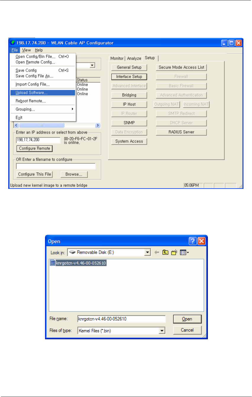
1. From the File menu, select Upload Software, and the browse window
will appear.
183
WLAN Cable Access Point 6220 CSU NTPM99CA Rel 2.0 Issue 5 Dec 2005
Figure 5-7
Upload Software Menu
2. Browse to the location of your .bin file, and select it.
Figure 5-8
Open binary Window
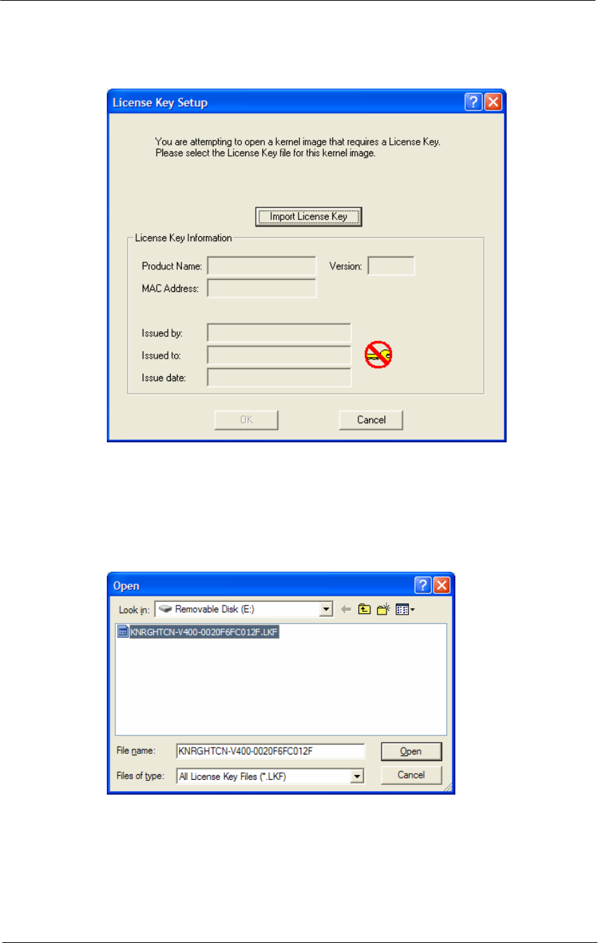
3. Click on the ‘Open’ button, and the "License Key Setup" screen will
appear:
184
WLAN Cable Access Point 6220 CSU NTPM99CA Rel 2.0 Issue 5 Dec 2005
Figure 5-9
License Key Setup Window
4. Click on the "Import License Key" button, and an "Open" dialog box
will appear:
Figure 5-10
Open License Key Window
5. Select the license file that corresponds to the Ethernet MAC of the unit
you are working with. (If you have "Licenses for this MAC address"
selected in the file type drop box, only the licenses for the MAC of the
current unit will appear.)
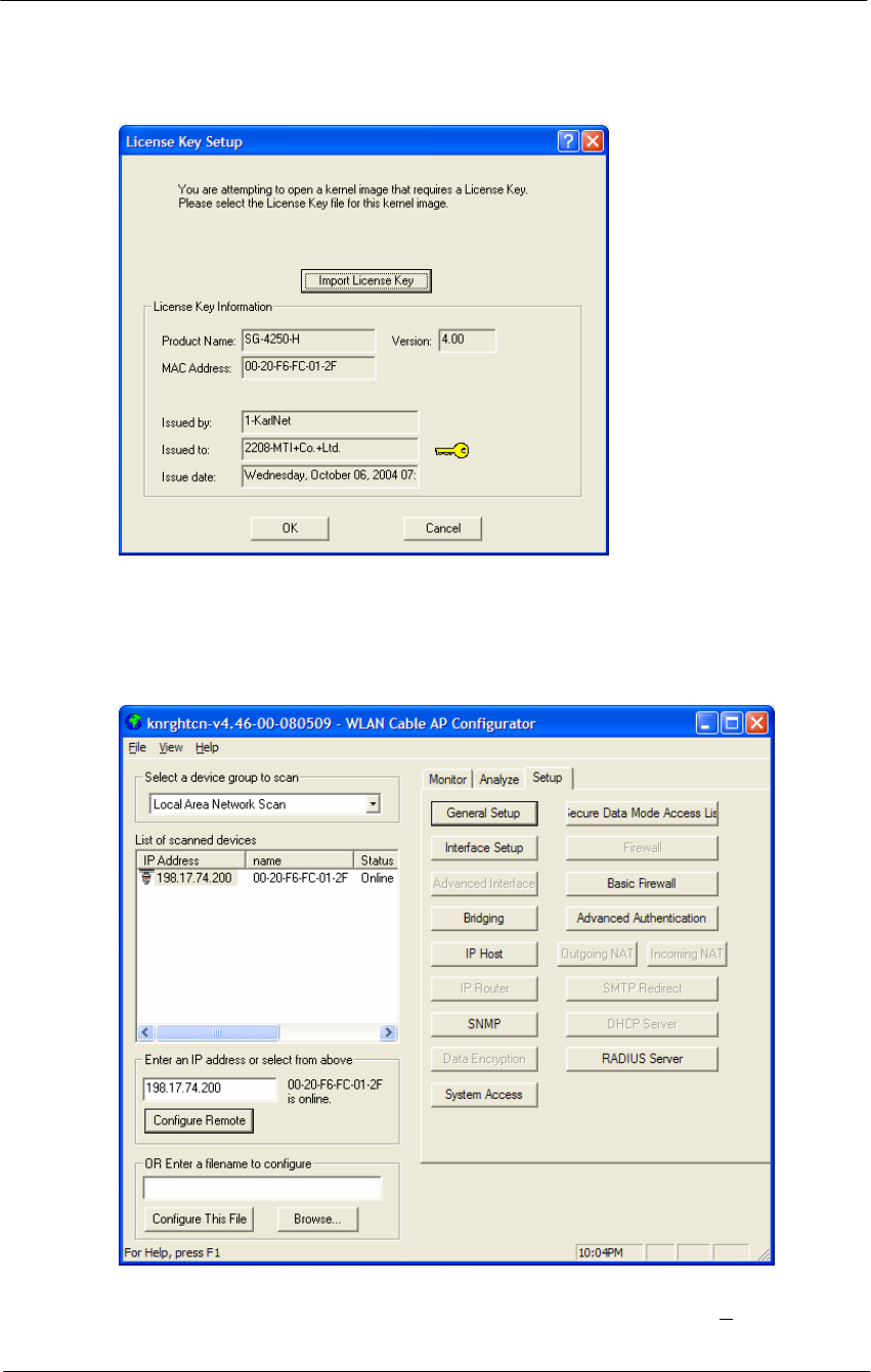
6. Click on the ‘Open’ button
185
WLAN Cable Access Point 6220 CSU NTPM99CA Rel 2.0 Issue 5 Dec 2005
Figure 5-11
License key setup window
7. Click on the ‘OK’ button
Figure 5-12
Setup window
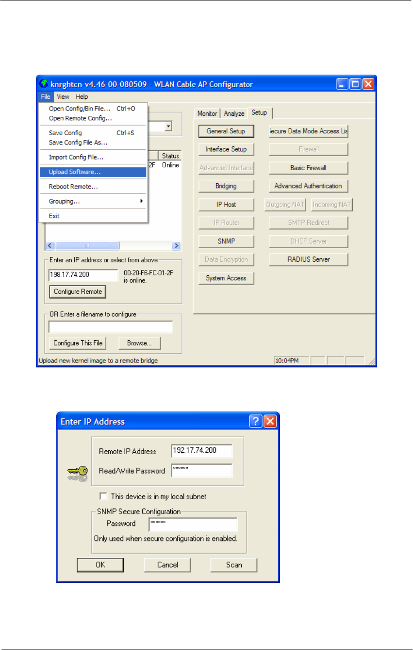
8. You can see an initial setup windows and then, From the File menu,
select upload software as below.
186
WLAN Cable Access Point 6220 CSU NTPM99CA Rel 2.0 Issue 5 Dec 2005
Figure 5-13
Selecting Upload Software
Figure 5-14
Enter IP address dialog
9. Enter the IP address of the unit to upload new software binary and Click
on the ‘OK’ button.
187
WLAN Cable Access Point 6220 CSU NTPM99CA Rel 2.0 Issue 5 Dec 2005
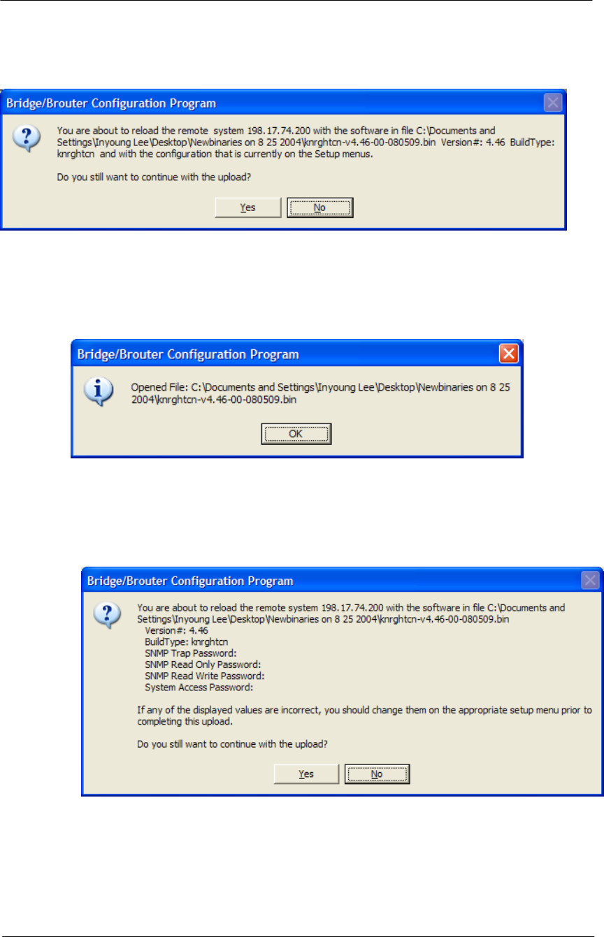
Figure 5-15
Uploading Confirmation Dialog 1
10. Click on the ‘OK’ button
Figure 5-16
Uploading Confirmation Dialog 2
11. Click on the ‘OK’ button
Figure 5-17
Uploading Binary Information Dialog Box
12. Click on the ‘OK’ button
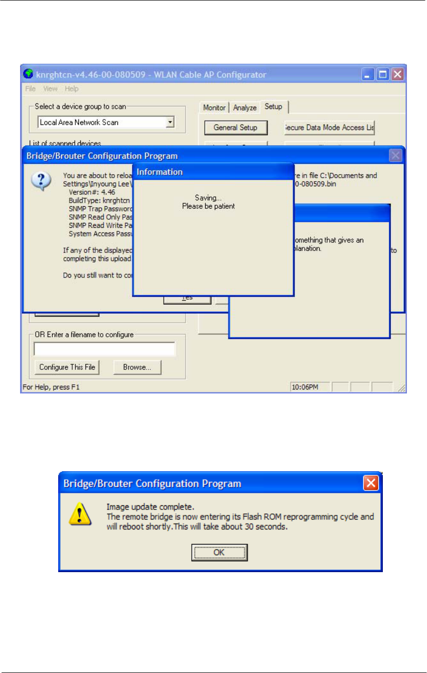
13. “Saving ….Please be patient” screen will appear as below
188
WLAN Cable Access Point 6220 CSU NTPM99CA Rel 2.0 Issue 5 Dec 2005
Figure 5-18
Saving software uploading window
14. Click on the ‘OK’ button
Figure 5-19
Reboot Message Dialog Box
15. Click on the ‘OK’ button
16. Software Uploading complete.

189
WLAN Cable Access Point 6220 CSU NTPM99CA Rel 2.0 Issue 5 Dec 2005
Reboot a Remote Station(APU and CSU)
The Reboot Remote option of the file menu allows you to reboot remote
devices if stations get dropped from the network.
Please follow the rebooting procedure to reboot a station from a remote
location.
1. Select File/Open Remote Config.
2. Enter the IP address and read/write password for the target base station.
3. Once the configuration has been read from bridge, select File/Reboot
Remote.
4. The APU or CSU will restart and run startup diagnostics.
Note: After approximately 60 seconds, the unit will start bridging operation
using the configuration parameters as they were stored in the remote station
prior to the Reboot.
Note: If you would like to display the configuration file or monitor the
unit's performance after a Reboot, you may have to wait until the unit
completes the start-up diagnostics. Once the startup diagnostics are
complete, the unit can be accessed again.

191
Troubleshooting

192
WLAN Cable Access Point 6220 NTPM99CA 01 Rel 1.0 Issue 3 Dec 2004
1. APU Power cannot be Turned ON.
Check that the CATV Power (45VAC ~ 95VAC) is supplied thorough the
coaxial line by measuring the AC Voltage Level.
If no power signal is detected at the end of the coaxial cable, you should search a
problem point on the CATV Network while moving up toward the ONU and
UPS Power supply.
2. LED 2(Link 1) is continuously blinking after running a long time and all
network entity including APU cannot receive IP address from DHCP
server.
Measure the RF signal level at the end of the coaxial cable or monitoring port in
the APU enclosure. Also check whether or not the RF signal level is beside the
range of required signal. If so, adjust the power level by tuning all related
network facility to meet the requirements for the operation of the Cable Modem.
* Normal Power level (DOCSIS): +15 to -15 dBmV
3. LED 3(Link 2)/LED 4(Radio Link) are turned off.
In the AP Configurator, select and click the setup tap, move to “interface” to see
whether or not Ethernet 2 and 802.11 is enabled. If disabled, check each
interface. If the LED lights are still turned off in spite of this work, the APU
system may have failed. If so, contact the Nortel local representative or technical
support center.
4. How do I see and configure a setup parameter of the CSU without a radio
connection to the APU?
The only devices that will display in the Configurator local scan window are the
units in the same subnet as your management computer. If the device in question
is not displayed in your local scan window, change the IP address (Client PC) to
any one of the subnet IP address groups “198.17.74.XXX” and then, you can
find out the CSU entity with the IP address “198.17.74.254”.
5. Why can CSU setup a radio connection to the APU?
Such situations are caused by various reasons as below:
- Mismatching between the radio setup parameter of APU and that of CSU
+ Radio Channel
+ Network ID (NWID)
+ WEP Encryption Key
- Radio Link Designing Problem(Link Distance, Antenna Direction and so
on)

193
WLAN Cable Access Point 6220 NTPM99CA 01 Rel 1.0 Issue 3 Dec 2004
6. How many CSU subscribers can connect to a single WLAN Cable Access
Point (APU Secure Data mode)?
Eight CSU subscribers can connect to a single WLAN Cable Access Point in
secure data mode.
7. How does the number of CSU Secure Data modes affect wireless
throughput?
As more CSU Secure Data modes are added, the APU Secure Data mode Base
Station mode is still able to effectively manage the throughput of the overall
wireless link. Just as on any shared medium, each station's throughput is
determined by the overall usage of the wireless link. The more stations
transmitting on the link at a time, the lower each individual station's throughput
goes. However, Secure Data mode performs in such a way that up to a point, the
more heavily loaded the network becomes, the higher the overall throughput
becomes.
For example, due to the intricacies of our Adaptive Dynamic Polling algorithms
and Secure Data mode 'fairness' principles, a single-user FTP session does not
use all of the possible wireless bandwidth. But when performing several
different transfers to and from different CSU Secure Data modes, the actual
overall bandwidth of the Secure Data mode network increases. In general, the
heavier a Secure Data mode network is loaded, the higher the total bandwidth
used becomes.
8. How do I check throughput?
Network throughput can be tested and analyzed using the Ping Fill test. This test
dynamically fills the network connection with ICMP Echo (ping) packets and
waits for the responses from the target station. Since each packet sent is echoed
back to the sender, this tests the overall wireless throughput in both directions.
Choosing the correct parameters is crucial to obtaining accurate Ping Fill test
results. The speed at which the target station responds to the ICMP Echo packets
is crucial to correctly assess the speed of the wireless link.
The IP stacks in some PC operating systems, such as Microsoft Windows, often
do not respond quickly enough to the ICMP Echo packets to obtain an accurate
assessment of your network throughput. When running the Ping Fill test to a
Microsoft Windows system, your results may be slightly lower than normal
throughput.
9. How do I read the configuration from a device if I cannot see the unit in the
local scan window?
The only devices that will display in the Configurator local scan window are the
units in the same subnet as your management computer. For example your PC
has an IP address 64.22.33.13 with a subnet mask of 255.255.255.0 and your

194
WLAN Cable Access Point 6220 NTPM99CA 01 Rel 1.0 Issue 3 Dec 2004
device has an IP address of 65.23.11.2 with a subnet mask of 255.255.0.0. The
device in question would not display in your local scan window.
Even though you may be able to ping the unit it may not be visible in the local
scan window. In the Configurator, select the file menu, and then open remote
config and then type in the IP and the password. It may be necessary to select
the "this device is in my local subnet" check box to actually read the
configuration from the unit. Attempt to read the configuration with it un-checked
first. If the configuration cannot be read try with this box checked.
10. I seem to have lost or forgotten the read/write password to manage my
product.
How can I get back in to manage the unit?
If the read/write password has been lost or forgotten, there is only one thing that
can be done about this in order to be able to manage the unit again. The unit
must be put into force reload mode and the firmware must be reloaded. All
configuration settings will be lost. Physical access to the unit is required in order
to accomplish this procedure.
11. I am performing a wireless link test from a CSU Secure Data mode and one
of my CSU Secure Data modes on the other side of my base station is
showing up, is this a problem?
It is a normal function to be able to see the other units in the wireless link test
this way. This shows you what devices are within range so that the radio can
"hear”. As long as the units are set as Secure Data mode CSU Secure Data
modes, there is no way they will actually be communicating with each other.
They are receiving radio signals from each other that they have to interpret and
dump. This is not an optimal solution and should be changed when it is practical
to do so by isolating antennas, changing polarity or reducing output power if
possible.
12. Please provide the list of parameters for the different levels of signal
strengths i.e. No Connection, Poor, Acceptable, Good, and Excellent. How
do I determine what is good and bad?
What these values will mean, is somewhat specific to the environment being
worked under. For example, a Signal to Noise Ratio of 15 may be fine for one
area and 15 may not work very well in a high noise area. So here are some
general guidelines. Keep in mind all the information below is related to Secure
Data mode, for 802.11b mode replaces retransmit with dropped packets:
There are some further items to note:
Link planning should be done in your general geographic area and your links
should be set up with an extra margin that your company determines.
Links are best performed when possible with high gain antennas as opposed to

195
WLAN Cable Access Point 6220 NTPM99CA 01 Rel 1.0 Issue 3 Dec 2004
low gain amplified antennas
Noise is typically introduced by failing amplifiers and problems with connectors
and defective radios. Signal typically drops with bad cabling, connectors or
antenna misalignment, radio power issues Network ID and Channel values being
the same, may help stability in marginal links.
Marginal (sporadic links) typically occur in SNR ranges from 5-9, 10-15 usually
will keep association with retransmits or some packet loss. SNR from 16 and up
usually are acceptable for every day operation.
If SNR is over 25 and throughput is poor, overdriving or multi-path may be the
cause of the problems.
Secure Data Mode Station Entries - Provides information on octal packet,
retransmitted packets and failed packets. A value other than 0 under failed
packets typically points to a link issue. Keep in mind TC retransmits a packet 9
times, (with the initial packet 10 total).
This has occurred and the packet has been dropped when a failure occurs.
Retransmits should be 15% or less of total transmits, this may indicate signal,
noise or antenna alignment issues.
Remote Statistics - Check each Ethernet Interface, any errors or collisions may
be signs of link speed or greater network related issues.
Check each wireless interface. Specifically, compare the Frame Check Sequence
errors to the bytes in values. Typically FCS occurs on any wireless connection.
This should only be a concern if the value exceeds approximately 10% of the
bytes in value. This may be an indicator of signal/multi-path issues.
13. Can I block unwanted MAC addresses from the Ethernet interface?
It is possible to set an Access Control List to set all of your allowable MAC's on
the Ethernet (everything else on the Ethernet will be denied) by reading the
configuration from the unit with the WLAN Cable AP Configurator. Go to the
Setup tab -- General Setup -- Select the Mac Authentication Access control radio
button and click OK. Then select the Setup tab -- Advanced Authentication --
check the Access Control List and then click the Setup button. Add all your
allowable MAC's and select the Ethernet interface to apply the ACL.

197
Appendix
A. Specification
B. DOCSIS Specification
C. Antenna
D. Enclosure Dimension

198
WLAN Cable Access Point 6220 NTPM99CA 01 Rel 1.0 Issue 3 Dec 2004
Appendix A. Specification
Access Point Unit (APU)
Physical
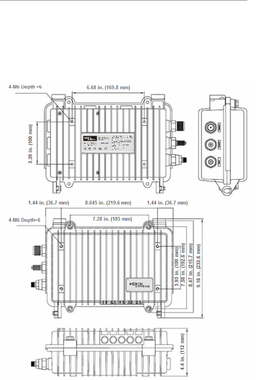
Dimension
z 300(W) * 232.6(L) * 112(D) [Unit: mm]
z 11.81 (W) * 9.157 (L) * 4.40 (D) [Unit: inch]
Weight(without antenna): 6.9234 lbs(<7 lbs), 3.14 Kg
Enclosure: Strong Aluminum alloyed –Steel with anodizing coating
surface(Waterproof, EMI protection, Vibration Robust)
Power consumption: Max 12W(65Vac/180mA)
System elements: Access Point, Cable Modem, HFC Signal Filter, Power
Supply Unit
Interface Ports: Coaxial Port, Monitoring Port, Antenna Port (N-type)
Strand mountable and Antenna included
Wireless LAN
Wireless LAN standard: IEEE 802.11a/b/g
Frequency Band & Channel
2.4~2.4835GHz(ISM), 5.725 ~ 5.825GHz (U-NII Upper band)
802.11a(U-NII)
Frequency Channel
149 5745 MHz
153 5765 MHz
157 5785 MHz
161 5805 MHz
802.11b/g(ISM)
Frequency Channel 6 2437 MHz
1 2412 MHz 7 2442 MHz
2 2417 MHz 8 2447 MHz
3 2422 MHz 9 2452 MHz
4 2427 MHz 10 2457 MHz
5 2432 MHz 11 2462 MHz
Modulation: DSSS(DBPSK,DQPSK,CCK), OFDM(16QAM, QPSK,BPSK)
Data rate: 1Mbps, 2Mbps, 5.5Mbps, 11Mbps, 6Mbps, 9Mbps, 12Mbps,
18Mbps, 24Mbps, 36Mbps, 48Mbps, 54Mbps
Power adjustment (4 steps): 100%(Max), 50%, 25%, 12.5%

199
WLAN Cable Access Point 6220 NTPM99CA 01 Rel 1.0 Issue 3 Dec 2004
Maximum Transmit Power(Radio)
Output power table [dBm] in 802.11a
CH 5745MHz 5765MHz 5785MHz 5805MHz remark
6~24 Mbps 11.6 12.1 11.8 12.0 +/-1.5dB
36 Mbps 11.3 11.6 11.4 11.6 +/-1.5dB
48 Mbps 11.2 11.5 11.2 11.5 +/-1.5dB
54Mbps 10.6 10.8 10.2 10.6 +/-1.5dB
Output power table [dBm] in 802.11g
CH 2412 MHz 2447MHz 2462 MHz remark
6~24 Mbps 3 13.2 2.3 +/-1.5dB
36 Mbps 2.6 12.8 1.8 +/-1.5dB
48 Mbps 2.3 12.6 1.8 +/-1.5dB
54Mbps 2.3 12.6 1.7 +/-1.5dB
Output power table [dBm] in 802.11b
CH 2412 MHz 2447MHz 2462 MHz remark
1 Mbps 8 13 7.7 +/-1.5dB
2 Mbps 8 13 7.7 +/-1.5dB
5.5 Mbps 8 13 7.4 +/-1.5dB
11 Mbps 8 13 7.2 +/-1.5dB
Max EIRP [dBm] for PMP topology
- 802.11a with 22dBi antenna (NTA-5807): 34.1 dBm
- 802.11g/b
Mode NTA-2407 NTA-2412 NTA-2400 EIRP Limit
11g 27.2 22.2 20.2 36 dBm(4W)
11b 27 21 20 36 dBm(4W)
Note: Unlike 802.11b (DSSS), in case of 802.11g (OFDM), it’s been
calibrated to transmit much less output power than 802.11b because the
transmit power at both edge channels is restricted by FCC rules.
Receive sensitivity: Min. -71dBm at 54Mbps / Min -88dBm at 11Mbps
Cable modem
[Receiver/Downstream]

200
WLAN Cable Access Point 6220 NTPM99CA 01 Rel 1.0 Issue 3 Dec 2004
Downstream Modulation: 64/256 QAM
Symbol Rate: 5.056941Msym/sec(64QAM), 5.360537Msym/sec (265QAM)
Frequency Range: 88-860 MHz
Channel Width : 6MHz
Maximum Downstream Data Rate: 27/38 Mbps {64QAM/256QAM}
RF Input Sensitivity:
A. Cable modem only : -21 to +21dBmV
B. Cable Modem + HFC Filter: -15 to +15dBmV
64 QAM Performance @ 23 dB Es/No: BER < 10E-8
Input Impedance: 75 Ohm
[Transmitter/Upstream]
Frequency Range: 5-42 MHz
Bandwidth
A-TDMA : 200,400,800.1600,3200,6400KHz
S-CDMA : 1600,3200,6400KHz
Upstream Modulation: QPSK/16QAM, 32QAM/64QAM(A-TDMA),
128QAM(S-CDMA)
Encoding: Reed-Solomon (RS), Trellis Coded Modulation (TCM)
Max Data Rate: 30.72 Mbps(DOCSIS 2.0)
RF Output Level: -2 to +60 dBmV
Output Power Level
A-TDMA : +5 ~ +61dBmV (32QAM,64QAM)
+5 ~ +61dBmV(8QAM,16QAM)
+5 ~ +62dBmV(QPSK)
S-CDMA : +6 ~ +55dBmV(All modulation)
Gain Control Range: 63dB
Frequency Stability: ± 5 kHz
Output Impedance: 75 Ohms
Software
Firmware : APU Secure Data Mode (Base Station)
Wireless Service Protocol : Secure Data Mode, Dynamic Polling
MAC access control – 32 local MAC Address Table (SDM mode)*
Standard RADIUS server support
Wired Equivalent Privacy encryption - 64, 128, AES
Firewall (ICMP/UDP/TCP/IP Protocol Filtering)
Layer 2 Protocol Filtering
BOOTP/DHCP (Server, Relay, Client), Static IP
NAT (Incoming/Outgoing)
Routing Protocol (RIP v2, Static)

201
WLAN Cable Access Point 6220 NTPM99CA 01 Rel 1.0 Issue 3 Dec 2004
Restriction of Broadcast Storm
SNMP v1, Software upgrade via TFTP (only applicable to cable modem)
GUI Program : Windows Based
Throughput Analysis: Ping Fill
Radio Performance Testing Tool: Antenna Alignment
Remote Statistics Monitoring
SNMP Traps
MIB II
(*) There is a limit of 32 if you use MAC address and comment per entry. However
each APU can support 64 CSU's associating with it in SDM mode if you use only
MAC address per entry. If you use a RADIUS server for this setup, there is no
limitation.
Environmental
Operating Temperature: -40°C to +60°C
Storage Temperature: -40°C to +85°C
Humidity: 5% to 100% non-condensing
Weather Rating: IP67 weather tight
Operating Altitude/Solar Load Test: <3,000 meter above see level
Salt/Fog/Rust Resistance: ASTM B 117 (Tested for 30 days)
Shock & Vibration
z Operation
ETS 300 019-2-4 Class 4.1/4.1E: Subclass 4M3 IEC 68-2-64
ETS 300 019-2-3 referencies IEC 68-2-27 Shock tolerance
z Transportation(Non-operating & Shipping)
ETS 300 019-2-4 Class 1.2 (storage)
ETS 300 019-2-4 Class 2.3 (transportation)
Impact: GR-950-CORE section 6.4.7(ASTM D 2444 Tup “B” Nose Detail)
Chemical resistance of nonmetallic components
z CRC226 Water Displacement Lubricant
z WD40 Water Displacement Lubricant
z Cable Filling compound, as used in the field
z Splice encapsulating Compound
z Isopropy Alcohol Grade HPLC
z 3% H2SO4 (sulphuric acid)
z 0.2% NaOH (Sodium Hydroxide)
z Wasp & Hornet Spray
Rain resistance
z ETS 300 019-1-2 Class 2.3(transportation)
z ETS 300 019-1-4 Class 4.1(operating)
Immunity
z Radiated RF/EMV Field (IEC 61000 4-3): 5V/M (5 MHz ~ 1GHz)
z ESD(IEC 61000 4-2) : +/- 15kV (air) and +/- 8kV (contact)
z Surge (IEC 61000 4-5) : 6kV Combination Wave (IEEE C62.41)

202
WLAN Cable Access Point 6220 NTPM99CA 01 Rel 1.0 Issue 3 Dec 2004
Certification
Radio / EMC
z FCC CFR47 Part 15, Class A
Safety
z Plenum rated, UL 50, UL 60950-1

203
WLAN Cable Access Point 6220 NTPM99CA 01 Rel 1.0 Issue 3 Dec 2004
Corporate Service Unit (CSU)
Physical
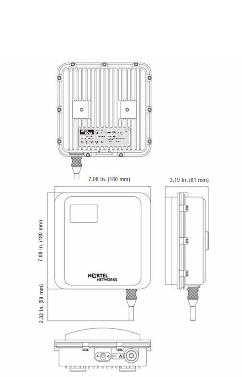
Dimension
180(W) * 180(L) *81(D) [Unit: mm]
180(W) * 239(L) *81(D) with the EMI cap [Unit:inch]
Weight(without antenna): 2.8659 lbs(1.30 Kg) with the mounting bracket kit
Enclosure: Gray UV Stabilized ASA(Cover), Aluminum and HDG Steel(Body)
Power consumption: Max 6W(3.3Vdc/1.5A)
System elements: Access Point, POE PD(Power Device)
Interface Ports: Ethernet Port(CAT5/POE/802.3af)
Pole mountable and Built-in type Antenna
Pole mountable and Built-in type Antenna Wireless LAN
Wireless LAN standard: IEEE 802.11a/b/g
Frequency Band & Channel
2.4~2.4835GHz(ISM), 5.725 ~ 5.825GHz (U-NII Upper band)
802.11a(U-NII)
Frequency Channel
149 5745 MHz
153 5765 MHz
157 5785 MHz
161 5805 MHz
802.11b/g(ISM)
Frequency Channel 6 2437 MHz
1 2412 MHz 7 2442 MHz
2 2417 MHz 8 2447 MHz
3 2422 MHz 9 2452 MHz
4 2427 MHz 10 2457 MHz
5 2432 MHz 11 2462 MHz
Modulation: DSSS(DBPSK,DQPSK,CCK), OFDM(16QAM, QPSK,BPSK)
Data rate: 1Mbps, 2Mbps, 5.5Mbps, 11Mbps, 6Mbps, 9Mbps, 12Mbps,
18Mbps, 24Mbps, 36Mbps, 48Mbps, 54Mbps
Power adjustment (4 steps): 100%(Max), 50%, 25%, 12.5%

204
WLAN Cable Access Point 6220 NTPM99CA 01 Rel 1.0 Issue 3 Dec 2004
Maximum Transmit Power(Radio)
Output power table [dBm] in 802.11a
CH 5745MHz 5765MHz 5785MHz 5805MHz remark
6~24 Mbps 11.6 12.1 11.8 12.0 +/-1.5dB
36 Mbps 11.3 11.6 11.4 11.6 +/-1.5dB
48 Mbps 11.2 11.5 11.2 11.5 +/-1.5dB
54Mbps 10.6 10.8 10.2 10.6 +/-1.5dB
Output power table [dBm] in 802.11g
CH 2412 MHz 2447MHz 2462 MHz remark
6~24 Mbps 3 13.2 2.3 +/-1.5dB
36 Mbps 2.6 12.8 1.8 +/-1.5dB
48 Mbps 2.3 12.6 1.8 +/-1.5dB
54Mbps 2.3 12.6 1.7 +/-1.5dB
Output power table [dBm] in 802.11b
CH 2412 MHz 2447MHz 2462 MHz remark
1 Mbps 8 13 7.7 +/-1.5dB
2 Mbps 8 13 7.7 +/-1.5dB
5.5 Mbps 8 13 7.4 +/-1.5dB
11 Mbps 8 13 7.2 +/-1.5dB
Max EIRP [dBm] for PMP topology
- 802.11a with 22dBi antenna (NTA-5807): 34.1 dBm
- 802.11g/b
Mode NTA-2407 NTA-2412 NTA-2400 EIRP Limit
11g 27.2 22.2 20.2 36 dBm(4W)
11b 27 21 20 36 dBm(4W)
Note: Unlike 802.11b (DSSS), in case of 802.11g (OFDM), it’s been
calibrated to transmit much less output power than 802.11b because the
transmit power at both edge channels is restricted by FCC rules.
Receive sensitivity: Min. -71dBm at 54Mbps / Min -88dBm at 11Mbps
Software
Firmware : APU CSU Secure Data Mode (Base Station)
Wireless Service Protocol : Secure Data Mode
MAC access control – 32 local MAC Address Table (SDM mode)*

205
WLAN Cable Access Point 6220 NTPM99CA 01 Rel 1.0 Issue 3 Dec 2004
Standard RADIUS server support
Wired Equivalent Privacy encryption - 64, 128, AES
Firewall (ICMP/UDP/TCP/IP Protocol Filtering)
Layer 2 Protocol Filtering
BOOTP/DHCP (Server, Relay, Client), Static IP
NAT (Incoming/Outgoing)
Routing Protocol (RIP v2, Static)
Restriction of Broadcast Storm
SNMP v1, Software upgrade via TFTP (only applicable to cable modem)
GUI Program : Windows Based
Throughput Analysis: Ping Fill
Radio Performance Testing Tool: Antenna Alignment
Remote Statistics Monitoring
SNMP Traps
MIB II
(*) There is a limit of 32 if you use MAC address and comment per entry. However
each APU can support 64 CSU's associating with it in SDM mode if you use only
MAC address per entry. If you use a RADIUS server for this setup, there is no
limitation.
Environmental
Operating Temperature: -40°C to +60°C
Storage Temperature: -40°C to +85°C
Humidity: 5% to 100% non-condensing
Weather Rating: IP67 weather tight
Operating Altitude/Solar Load Test: <3,000 meter above see level
Salt/Fog/Rust Resistance: ASTM B 117 (Tested for 30 days)
Shock & Vibration
z Operation
ETS 300 019-2-4 Class 4.1/4.1E: Subclass 4M3 IEC 68-2-64
ETS 300 019-2-3 referencies IEC 68-2-27 Shock tolerance
z Transportation(Non-operating & Shipping)
ETS 300 019-2-4 Class 1.2 (storage)
ETS 300 019-2-4 Class 2.3 (transportation)
Impact: GR-950-CORE section 6.4.7(ASTM D 2444 Tup “B” Nose Detail)
Chemical resistance of nonmetallic components
z CRC226 Water Displacement Lubricant
z WD40 Water Displacement Lubricant
z Cable Filling compound, as used in the field
z Splice encapsulating Compound
z Isopropy Alcohol Grade HPLC
z 3% H2SO4 (sulphuric acid)
z 0.2% NaOH (Sodium Hydroxide)

206
WLAN Cable Access Point 6220 NTPM99CA 01 Rel 1.0 Issue 3 Dec 2004
z Wasp & Hornet Spray
Rain resistance
z ETS 300 019-1-2 Class 2.3(transportation)
z ETS 300 019-1-4 Class 4.1(operating)
Immunity
z Radiated RF/EMV Field (IEC 61000 4-3): 5V/M (5 MHz ~ 1GHz)
z ESD(IEC 61000 4-2) : +/- 15kV (air) and +/- 8kV (contact)
z Surge (IEC 61000 4-5) : 6kV Combination Wave (IEEE C62.41)
Certification
Radio / EMC
z FCC CFR47 Part 15, Class A
Safety
z Plenum rated, UL 50, UL 60950-1
207
WLAN Cable Access Point 6220 NTPM99CA 01 Rel 1.0 Issue 3 Dec 2004
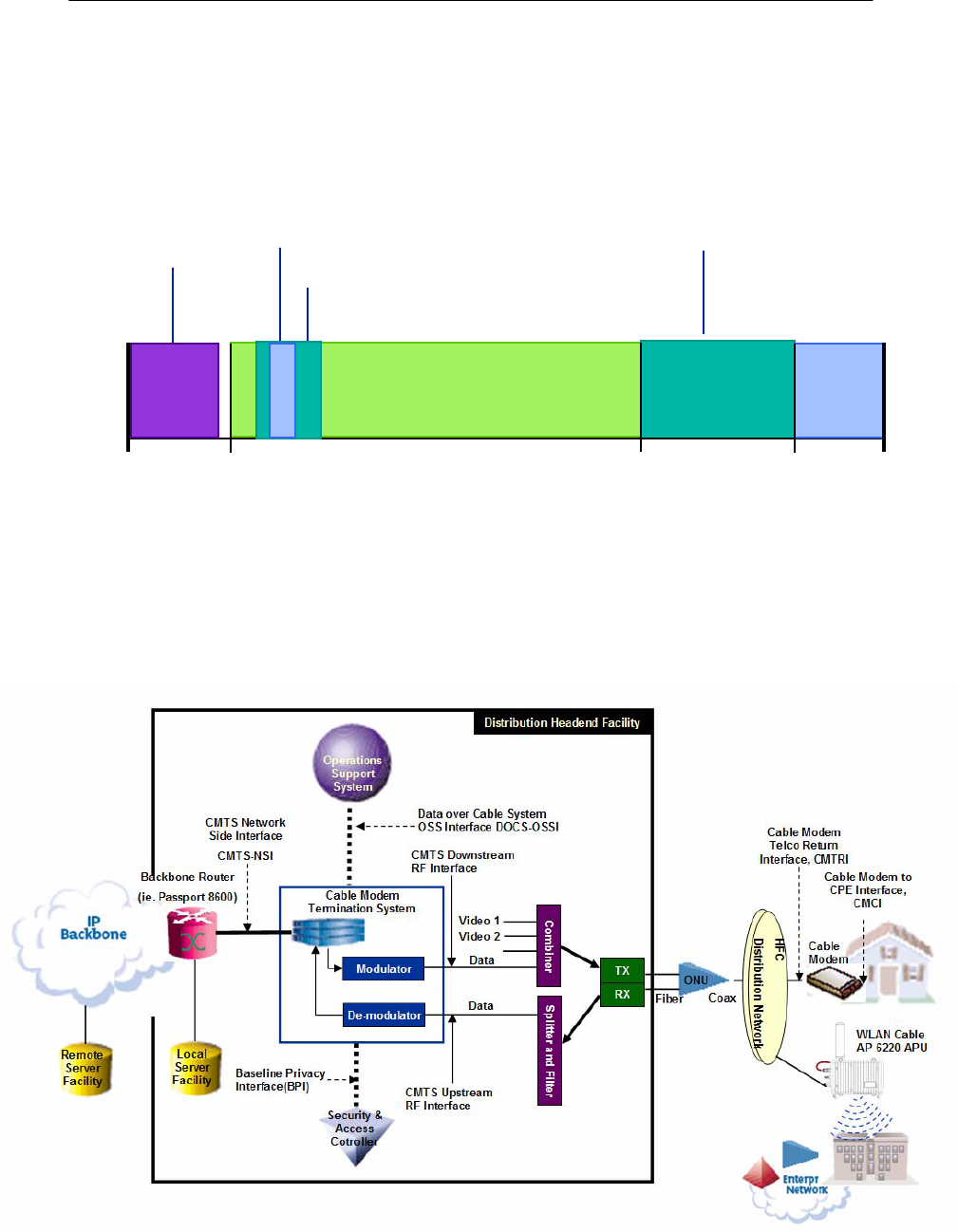
Appendix B. DOCSIS Specification
Figure A.1
CATV Frequency Range
CATV: UPSTREAM 5-42(30) MHz, DOWNSTREAM 50-750 (550) MHz
DATA: UPSTREAM 5-65MHz, DOWNSTREAM 88-750 (550) MHz
Figure A.2
DOCSIS Reference System Diagram
Upstream (DOCSIS)
54 MHz 750 MHz
5.75~41.75 MHz 552 MHz 864 MHz
CATV Channel
Data
Service
Downstream (DOCSIS)
208
WLAN Cable Access Point 6220 NTPM99CA 01 Rel 1.0 Issue 3 Dec 2004
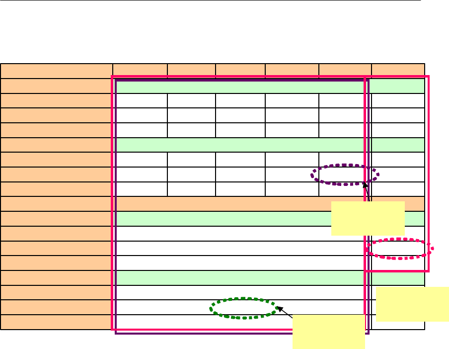
Table A.1
DOCSIS RF Specification Table
27.6Mbps
30.72Mbps
10.24Mbps
18.4Mbps
20.48Mbps
5.12Msps
9.2Mbps
10.24Mbps
5.12Msps
6.4MHz
37Mbps Effective Data Rate
42.9Mbps Total Data Rate
5.360Mbps SYMBOL Rate
256QAM Modulation TYPE
27Mbps Effective Data Rate
30.34Mbps Total Data Rate
5.057Msps SYMBOL Rate
64QAM Modulation TYPE
6MHz RF BW
9.2Mbps 4.5Mbps 2.3Mbps 1.2Mbps 0.6Mbps Effective Data Rate
10.24Mbps 5.12Mbps 2.56Mbps 1.28Mbps 0.64Mbps Total Data Rate
2.56Msps 1.28Msps 0.64Msps 0.32Msps 0.16Msps SYMBOL Rate
16QAM Modulation TYPE
4.6Mbps 2.3Mbps 1.2Mbps 0.6Mbps 0.3Mbps Effective Data Rate
5.12Mbps 2.56Mbps 1.28Mbps 0.64Mbps 0.32Mbps Total Data Rate
2.56Msps 1.28Msps 0.64Msps 0.32Msps 0.16Msps SYMBOL Rate
QPSK Modulation TYPE
3.2MHz 1.6MHz 800 KHz 400 KHz 200 KHz RF BW
DOCSIS 2.0
Upstream
Maximum
DOCSIS 1.1
Upstream
Maximum
DOCSIS
1.1&2.0
Down stream
209
WLAN Cable Access Point 6220 NTPM99CA 01 Rel 1.0 Issue 3 Dec 2004
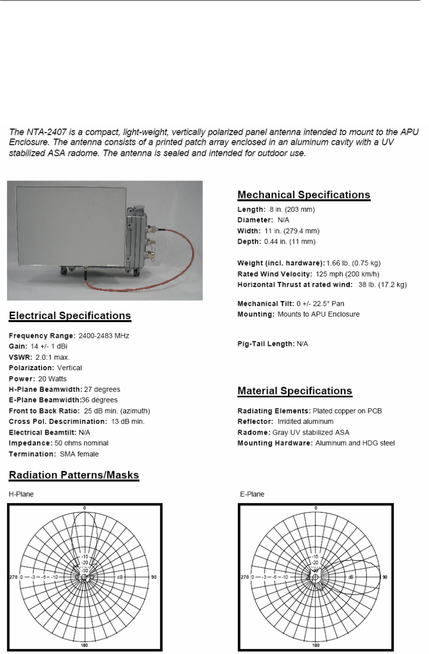
Appendix C. Antenna
NTA.2407 Panel Antenna (For 11b/g Radio Only)
210
WLAN Cable Access Point 6220 NTPM99CA 01 Rel 1.0 Issue 3 Dec 2004
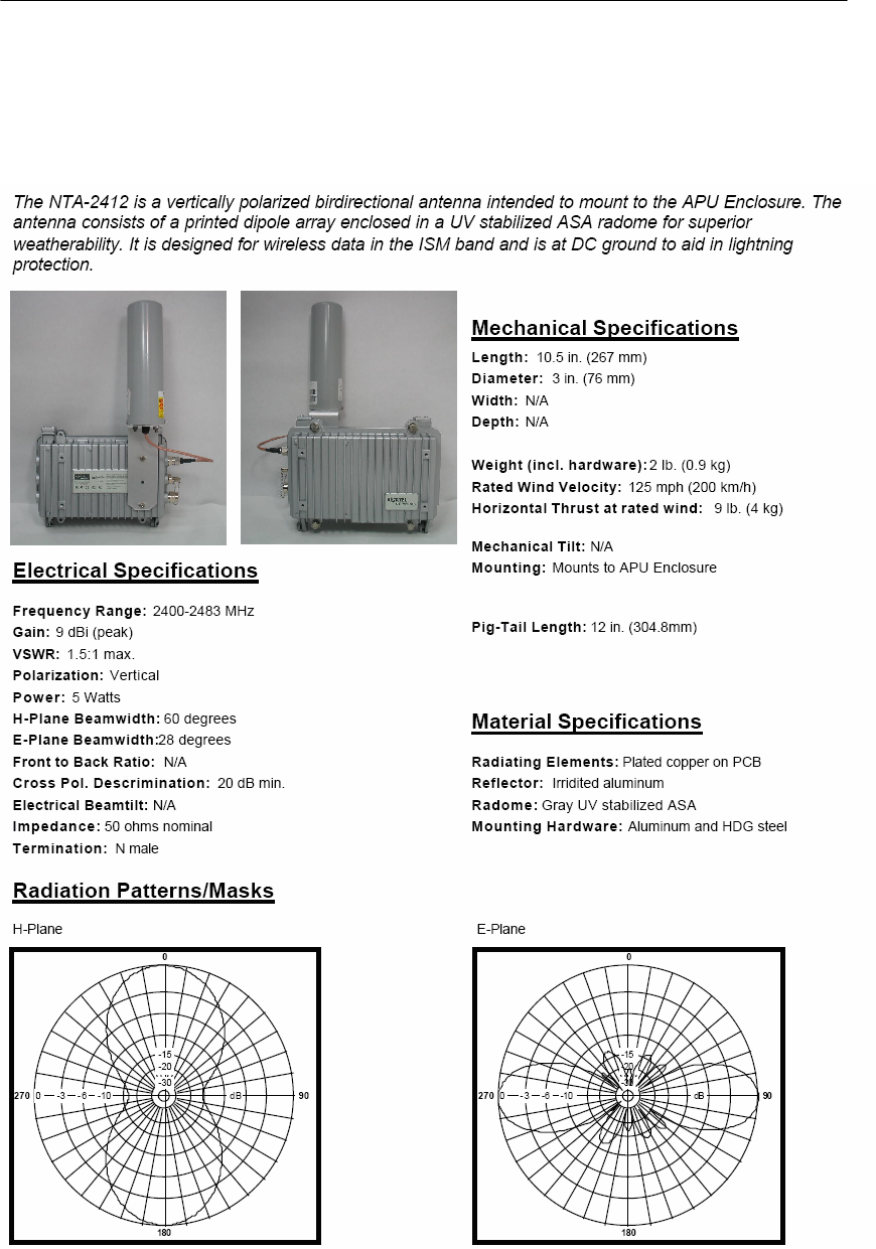
NTA.2412 Bidirectional Antenna (For 11b/g Radio Only)
211
WLAN Cable Access Point 6220 NTPM99CA 01 Rel 1.0 Issue 3 Dec 2004
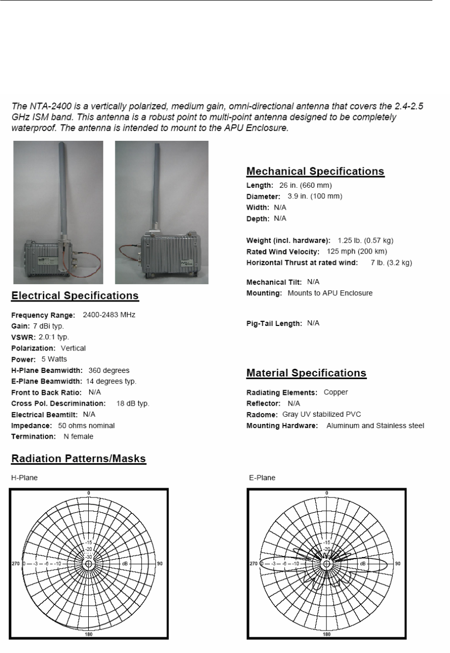
NTA.2400 Omni directional Antenna (For 11b/g Radio Only)

MT-485028/N
Electrical Specifications
Frequency Range : 5150-5875 MHz
Gain : 21.5 dBi @ 5150-5250 MHz
22 dBi @ 5250-5875 MHz
VSWR : 1.9 : 1 @ 5150-5250 MHz
1.7 : 1 @ 5250-5875 MHz
Polarization : Linear (Vertical or Horizontal)
Input Impedance : 50 (ohm)
Input Power : 6W (max)
3dB Beamwidth Azimuth : 9 degrees (typ)
3dB Beamwidth Elevation : 9 degrees (typ)
Front to Back Ratio : -35 dB (max)
Cross Polar Discrimination : -28dB
Connector : N-Type Female
Lightning Protection : DC Ground
Radiation Patterns/Masks
Azimuth Radiation Pattern
Midband Freq. 5470MHz
Mechanical Specifications
Length : 305 mm
Diameter : N/A
Width : 305mm
Depth : 15 mm
Weight : 1.2 ㎏ (max)
Wind Speed Survival : 220 ㎞/h
Wind Speed Operation : 160 ㎞/h
Wind Load (Survival) Front Thrust : 26.8 ㎏
Wind Load (Survival) Side Thrust : 1.3 ㎏
Material Specifications
Base Plate : Aluminum with chemical conversion coating
Radome : Plastic
Mounting Kit : MT-120018
Elevation Radiation Pattern
Midband Freq. 5470MHz
213
WLAN Cable Access Point 6220 NTPM99CA 01 Rel 1.0 Issue 3 Dec 2004
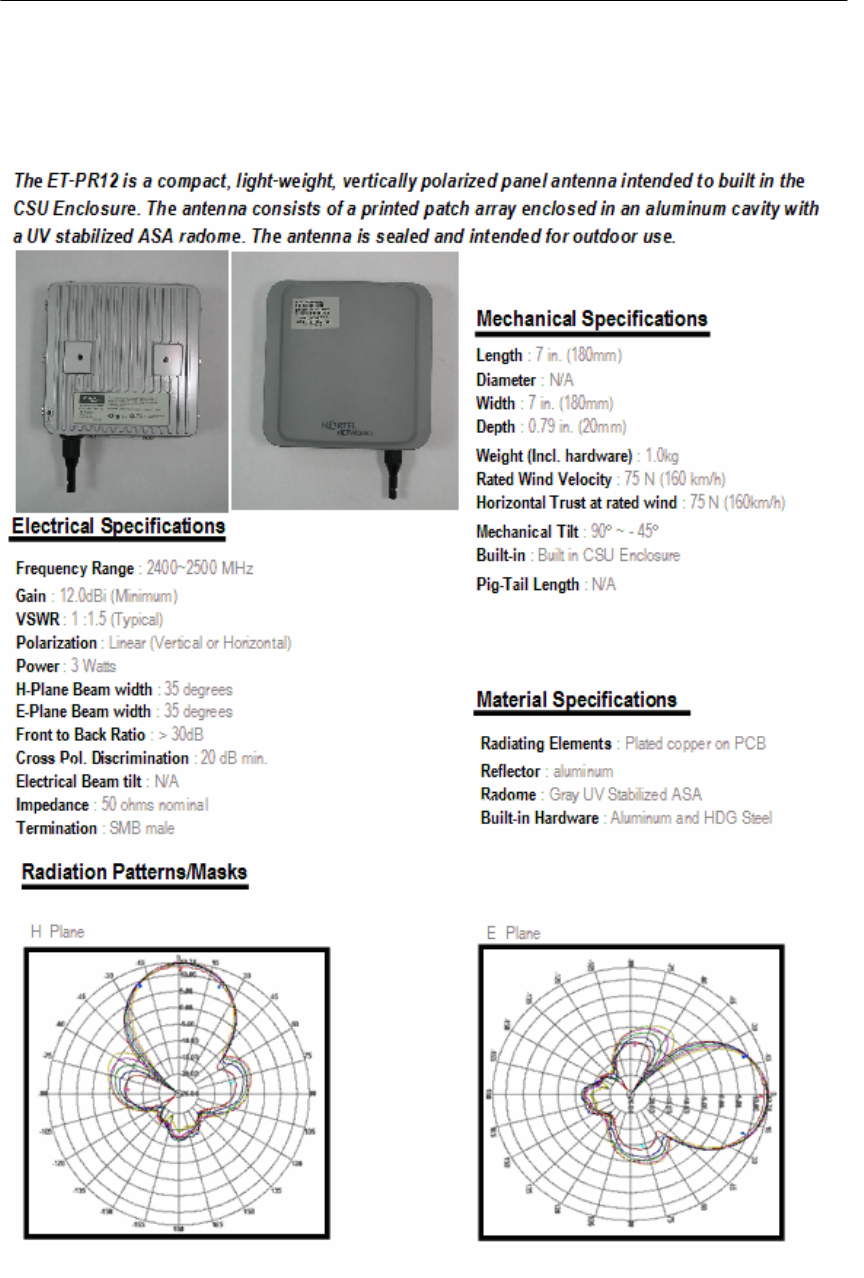
ET-PR12 Built-in Panel Antenna (For CSU 11b/g Radio Only)
214
WLAN Cable Access Point 6220 NTPM99CA 01 Rel 1.0 Issue 3 Dec 2004
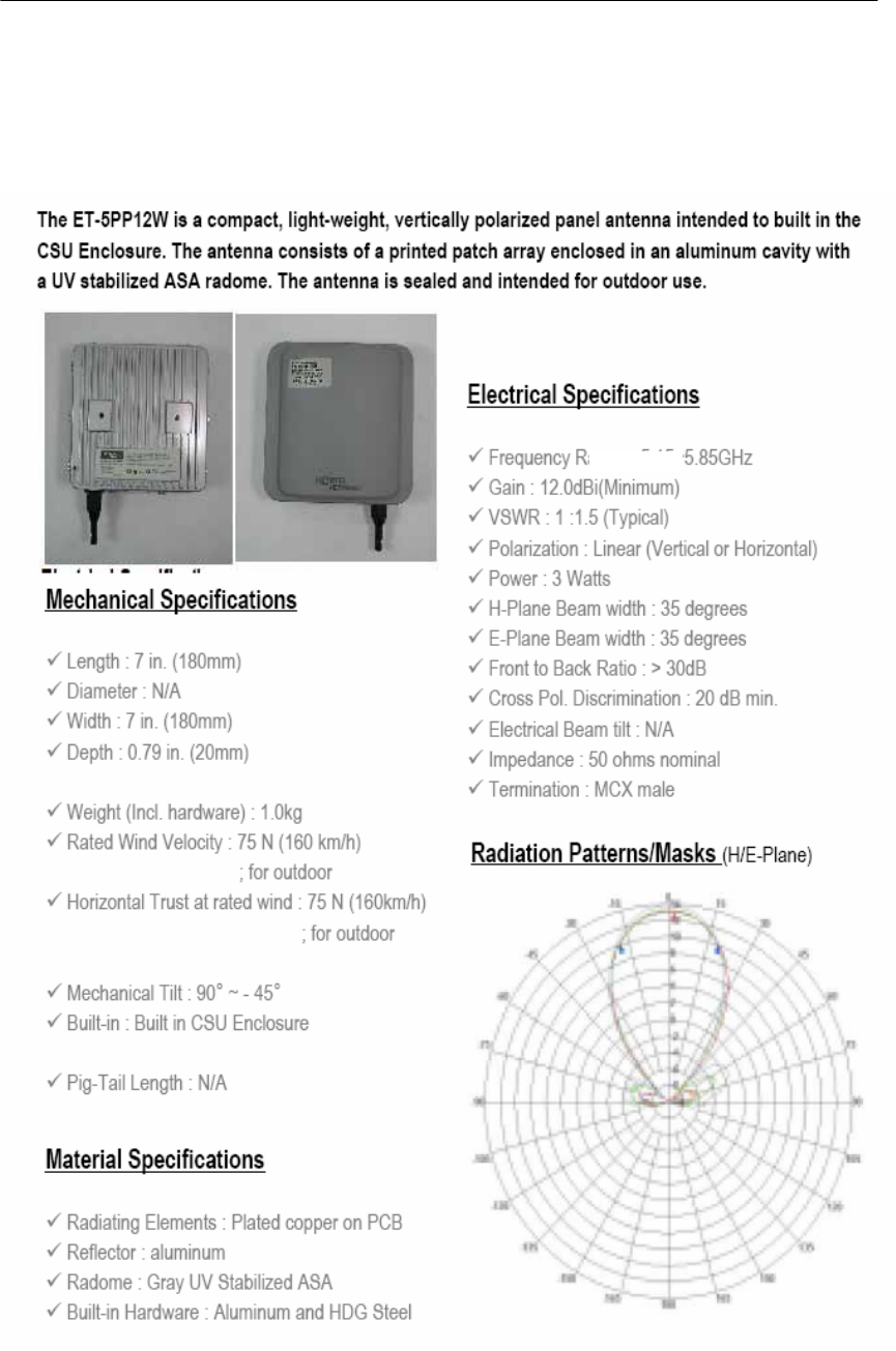
ET-5PR12W Built-in Panel Antenna (For CSU 11a Radio Only)
215
WLAN Cable Access Point 6220 NTPM99CA 01 Rel 1.0 Issue 3 Dec 2004
Appendix D. Enclosure Dimension
Access Point Unit (APU)
Figure A.3
APU Dimension
216
WLAN Cable Access Point 6220 NTPM99CA 01 Rel 1.0 Issue 3 Dec 2004
Corporate Service Unit (CSU)
Figure A.4
CSU Dimension