MTI APU11B01POE Access Point Unit User Manual
MTI Co., Ltd. Access Point Unit
UserManual.wiki
>
MTI
>
APU11B01POE User Manual
Manual
Navigation menu
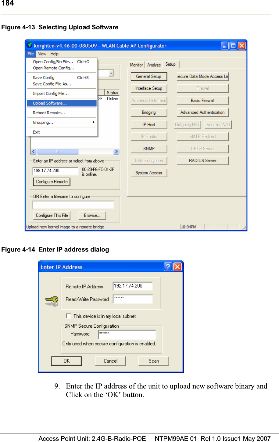
Upload a User Manual
Namespaces
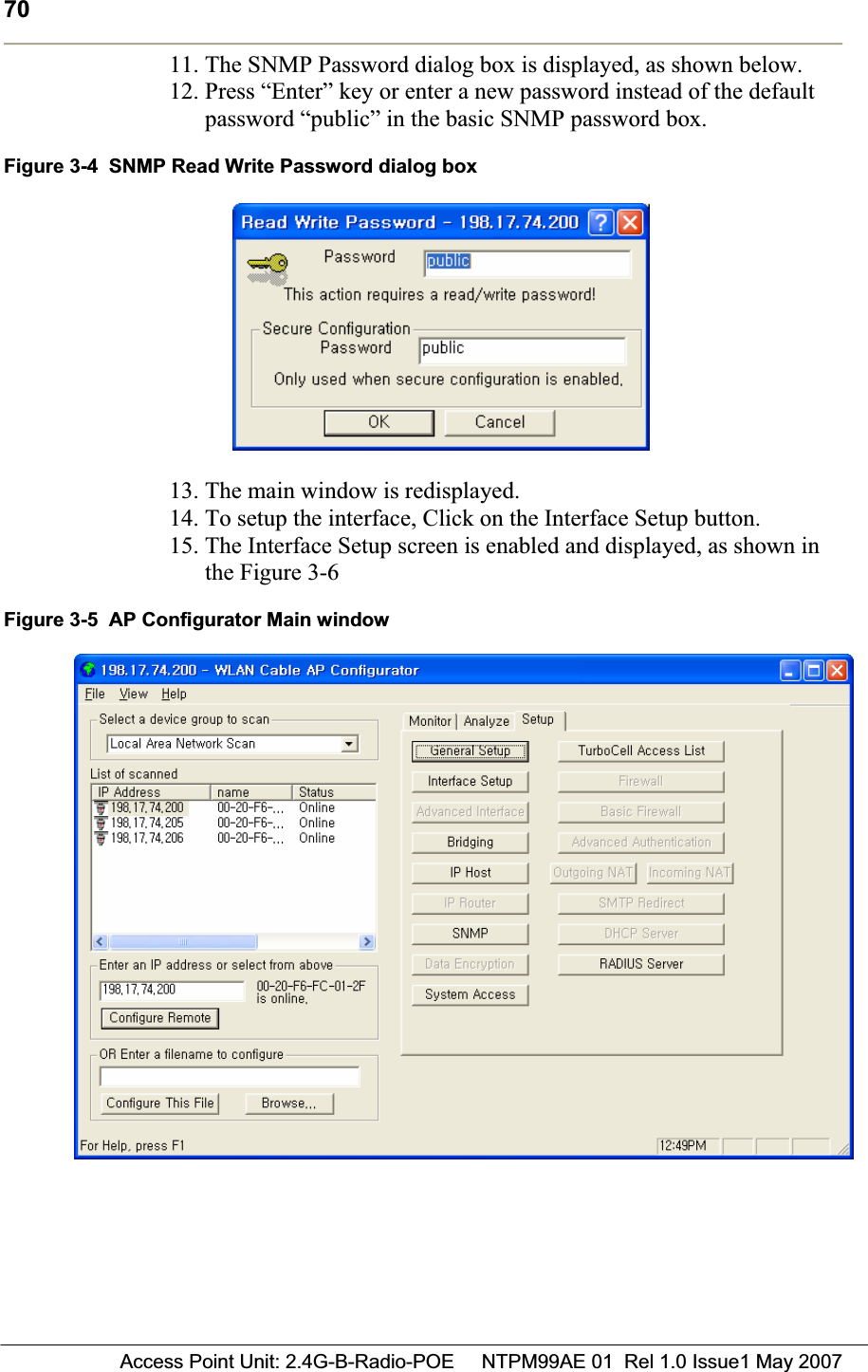
Wiki Guide
HTML
PDF
Info
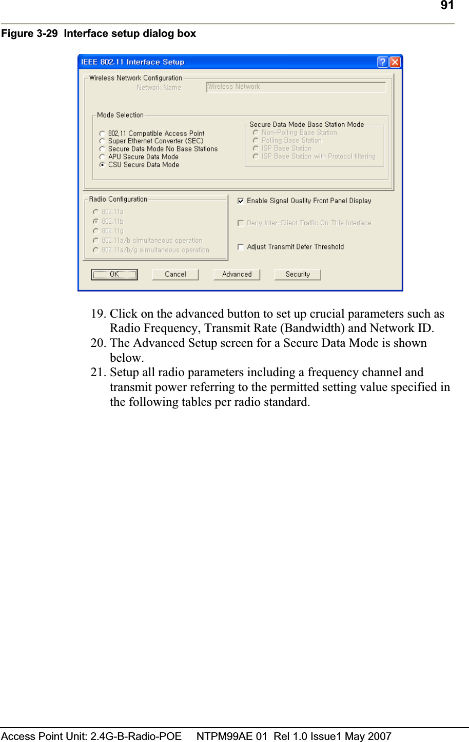
Views
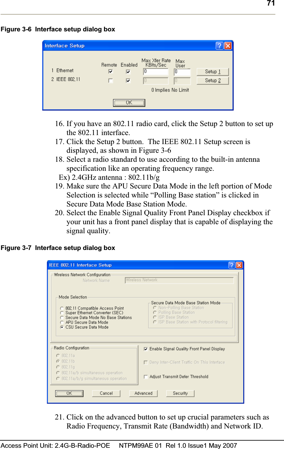
User Manual
Discussion / Help
Navigation
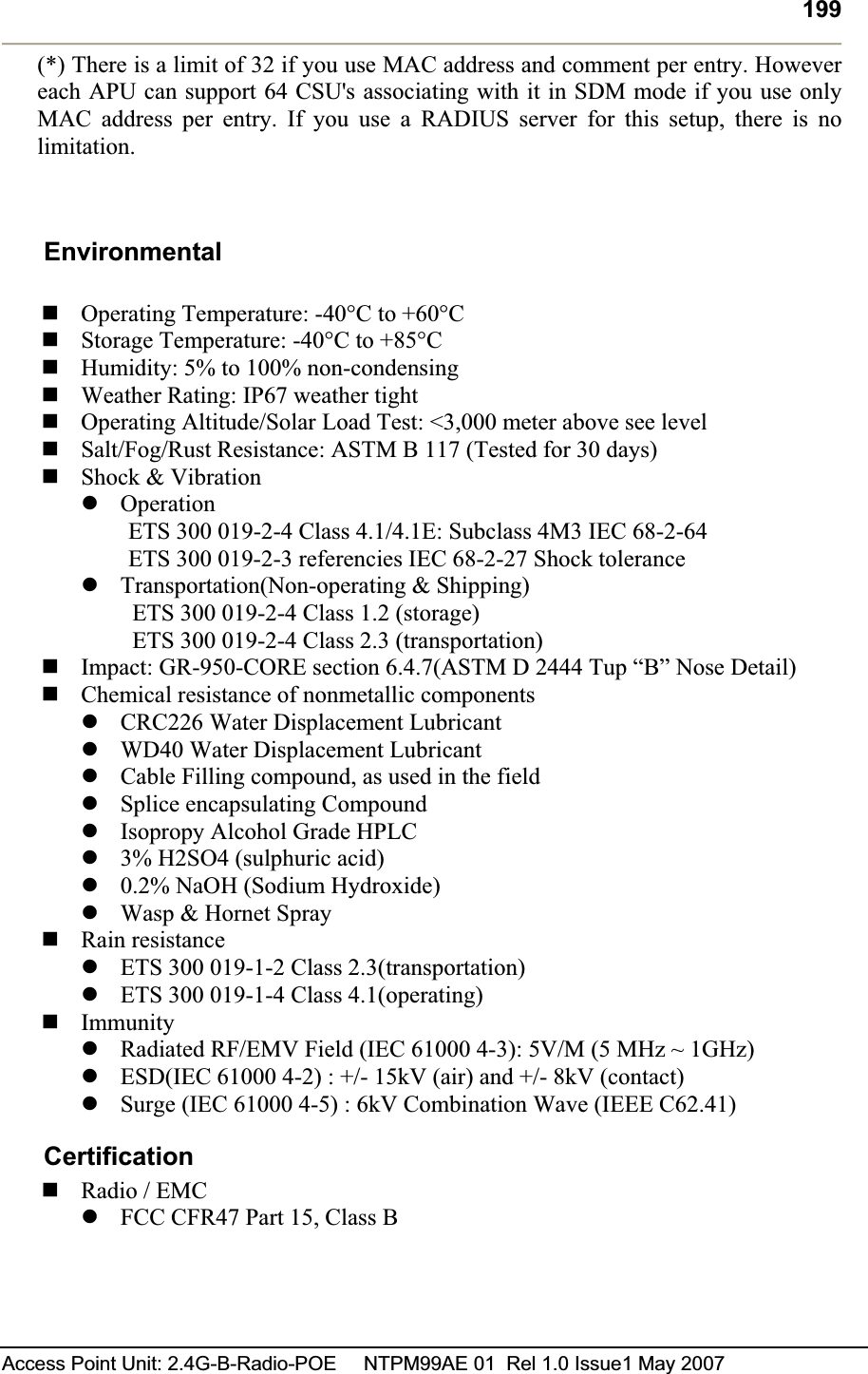
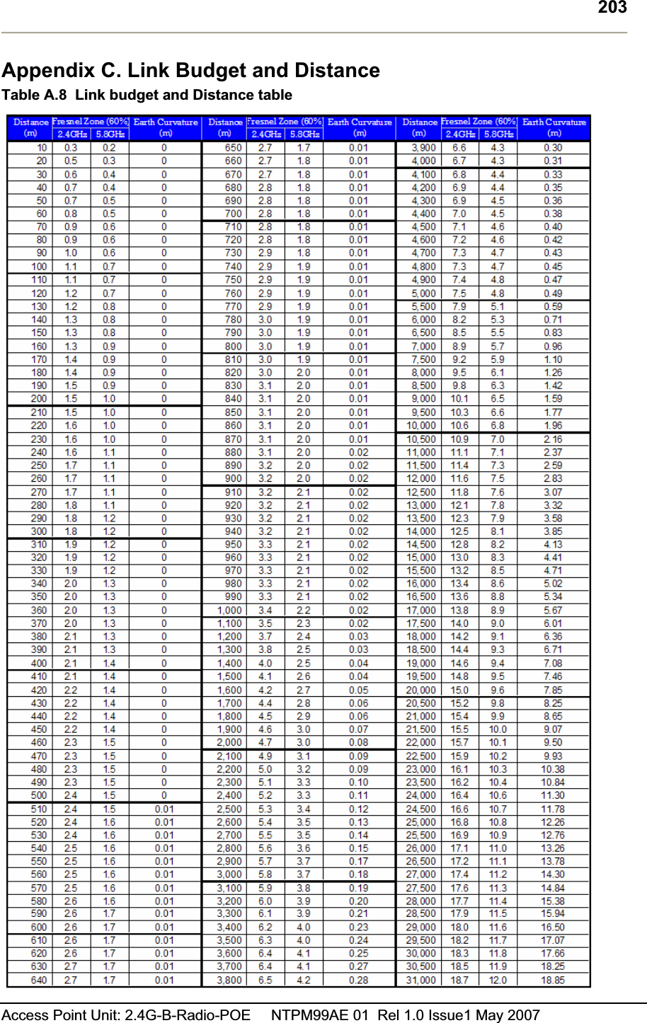
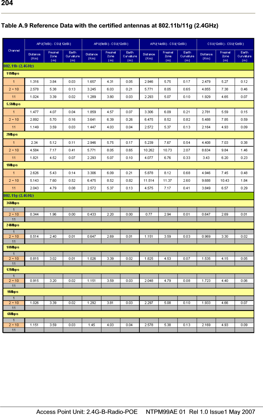
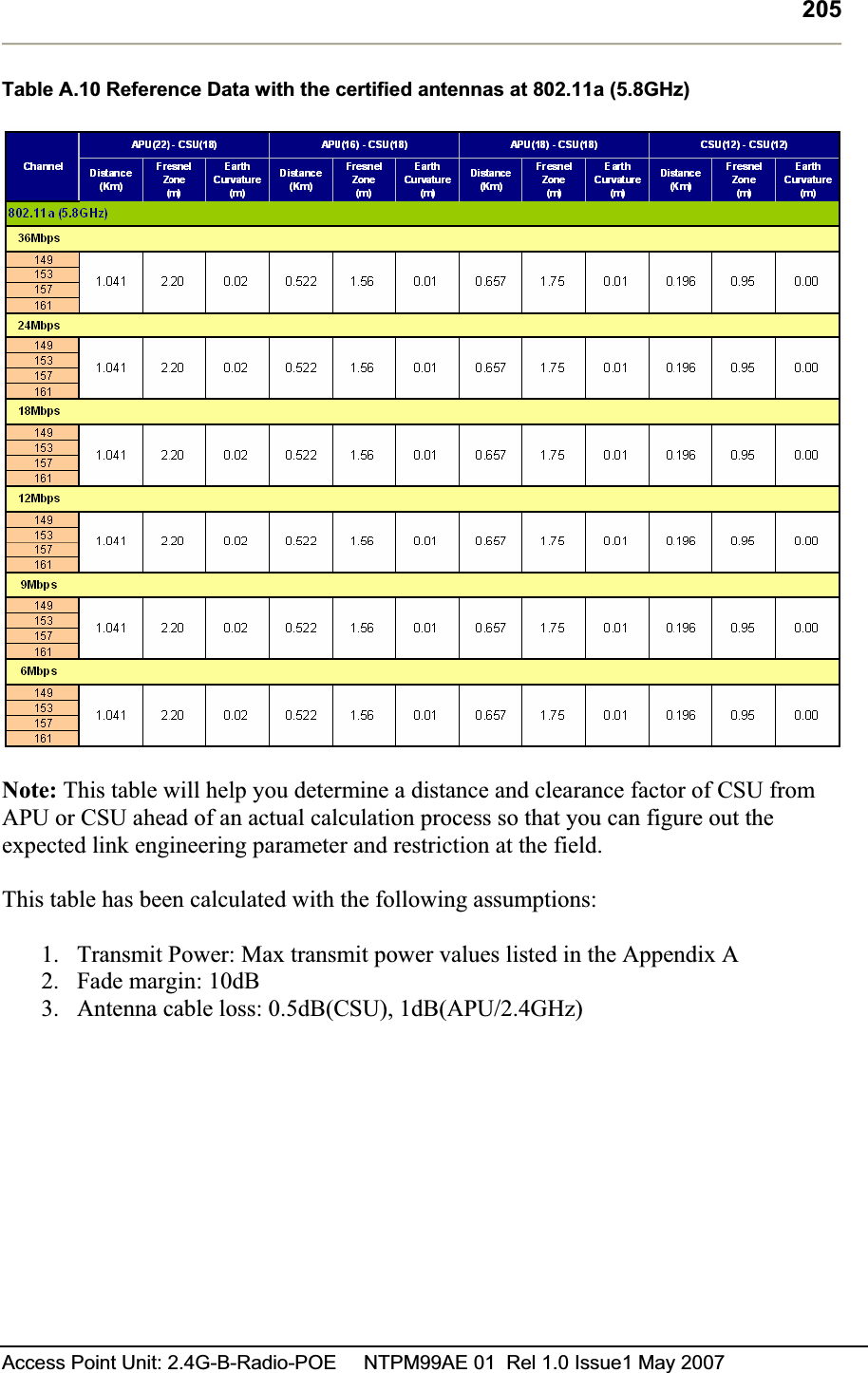
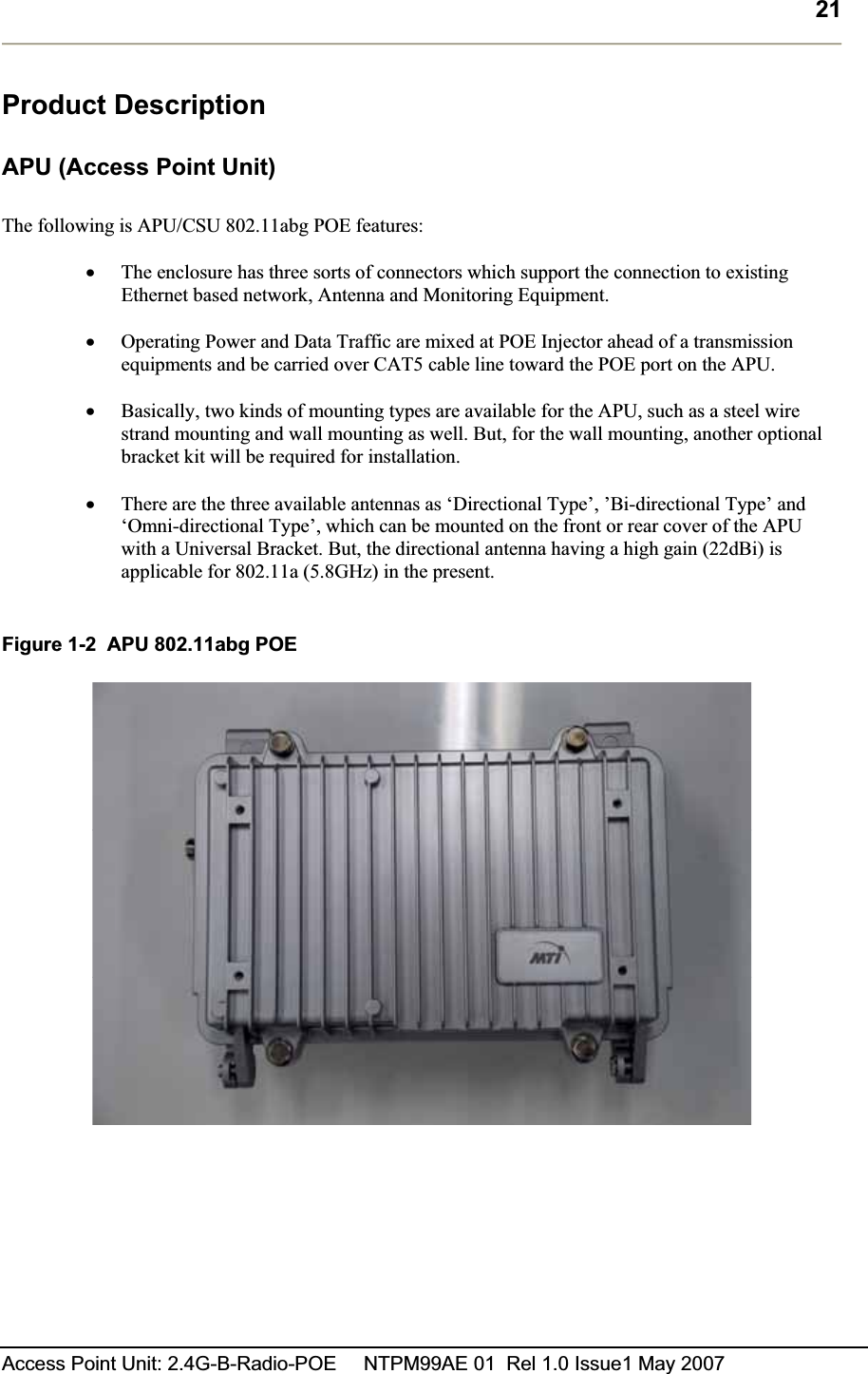
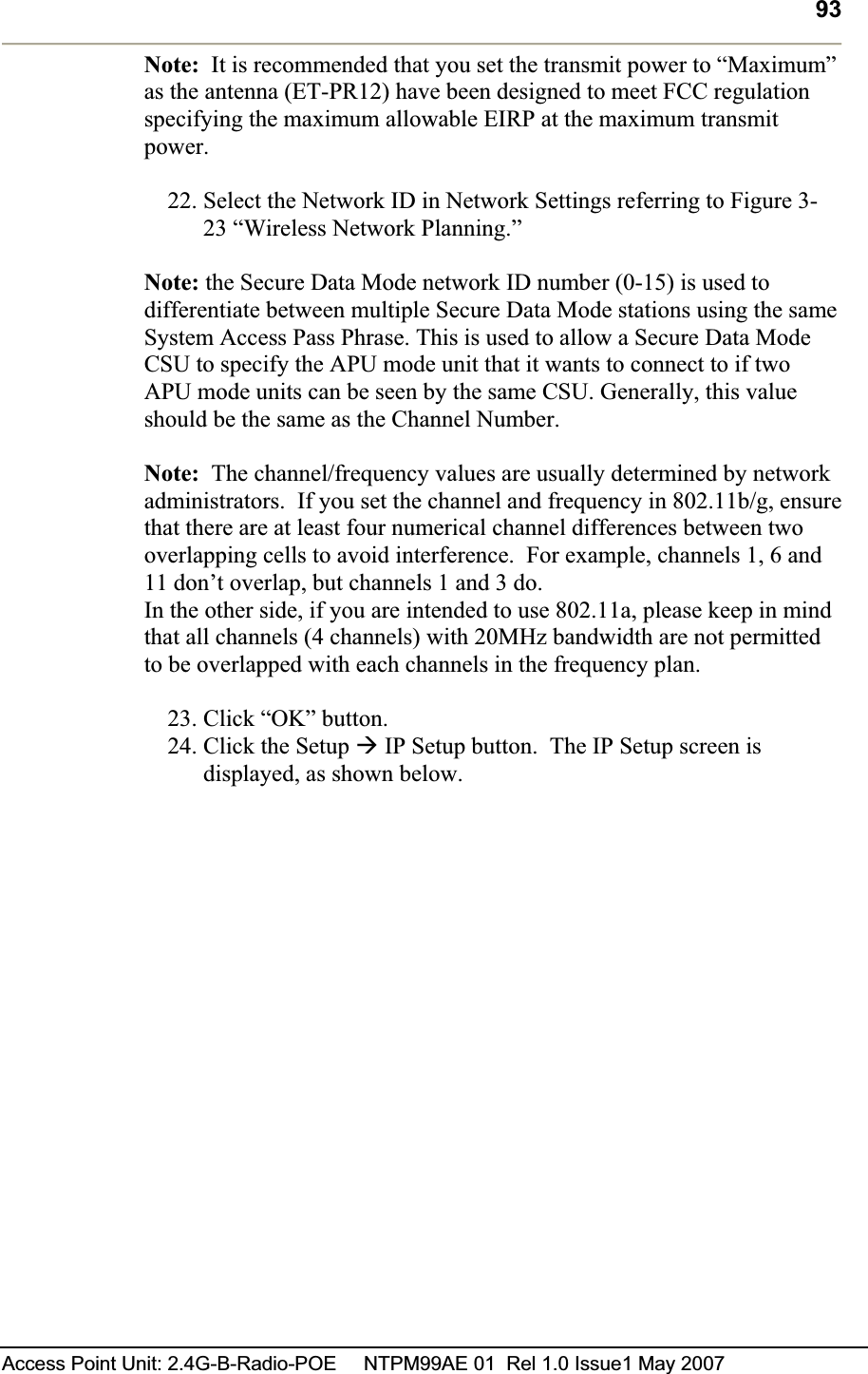
![11Access Point Unit: 2.4G-B-Radio-POE NTPM99AE 01 Rel 1.0 Issue1 May 2007 List of Tables TABLE 1-1 MODULES AND CONNECTORS (APU)........................................................................................23GTABLE 1-2. MODULES AND CONNECTORS (CSU) .......................................................................................27GTABLE 2-1 RADIO CHANNEL USAGE IN DIFFERENT COUNTRIES (802.11B/G)...............................................37GTABLE 2-2 RADIO CHANNEL USAGE IN UNITED STATES AND EU (802.11A)...............................................37GTABLE 2-3 FCC RULES PERTAINING TO WLAN.........................................................................................41GTABLE 3-1 SYSTEM MAIN PARAMETERS ....................................................................................................67GTABLE 3-2 SYSTEM MAIN PARAMETERS ....................................................................................................76GTABLE 3-3 SYSTEM MAIN PARAMETERS ....................................................................................................86GTABLE 3-4 SYSTEM MAIN PARAMETERS ....................................................................................................96GTABLE 3-5 RADIO LINK STATUS...............................................................................................................103GTABLE 3-6 AUTHENTICATION /ACCOUNTING...........................................................................................132GTABLE 3-7 TRAFFIC FILTERING ................................................................................................................138GTABLE 3-8 DEFAULT THRESHOLD VALUES ...............................................................................................142GTABLE 3-9 IP ROUTE LIST ........................................................................................................................152GTABLE 3-10 IP ARP TABLE......................................................................................................................157GTABLE A.1 802.11B(ISM) CHANNEL ASSIGNMENT ...................................................................................194GTABLE A.2 OUTPUT POWER TABLE [DBM] IN 802.11B..............................................................................195GTABLE A.3 OUTPUT POWER TABLE [DBM] IN 802.11B..............................................................................195GTABLE A.4 RECEIVER SENSITIVITY TABLE (802.11B)...............................................................................195GTABLE A.5 802.11B/G(ISM) CHANNEL ASSIGNMENT ...............................................................................197GTABLE A.6 OUTPUT POWER TABLE [DBM] IN 802.11B..............................................................................198GTABLE A.7 RECEIVER SENSITIVITY TABLE (802.11B)...............................................................................198GTABLE A.8 LINK BUDGET AND DISTANCE TABLE .....................................................................................203GTABLE A.9 REFERENCE DATA WITH THE CERTIFIED ANTENNAS AT 802.11B/11G(2.4GHZ)......................204GTABLE A.10 REFERENCE DATA WITH THE CERTIFIED ANTENNAS AT 802.11A(5.8GHZ)...........................205G](https://usermanual.wiki/MTI/APU11B01POE/User-Guide-821323-Page-11.png)
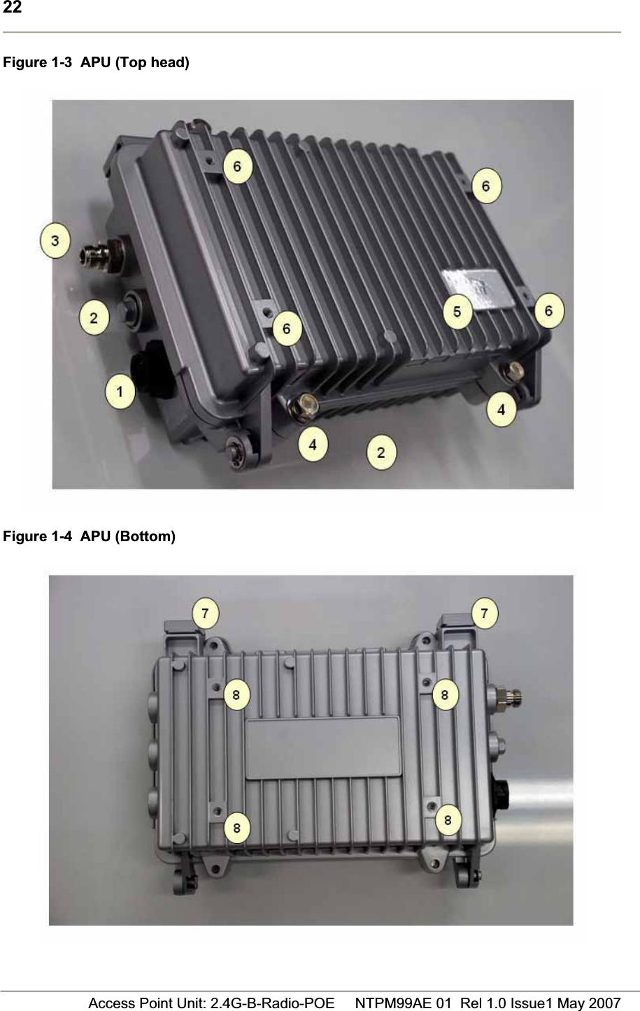
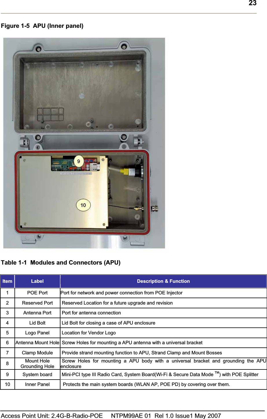
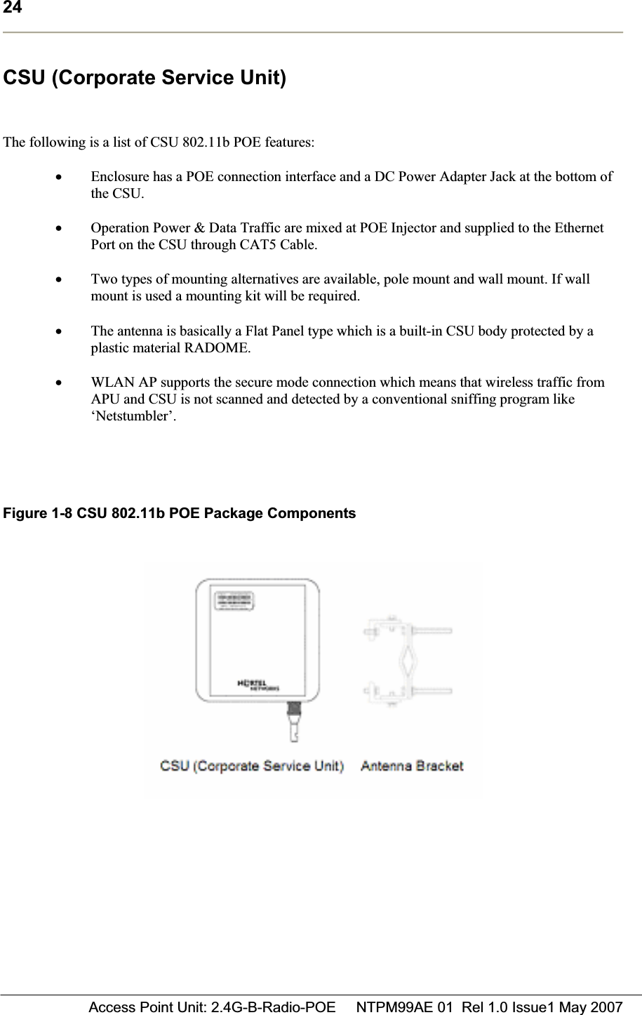
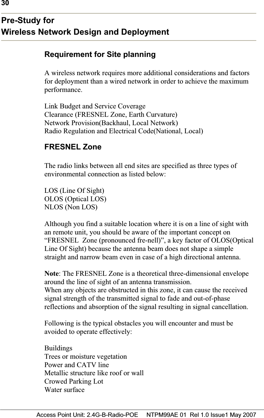
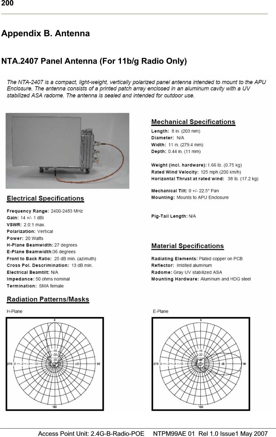
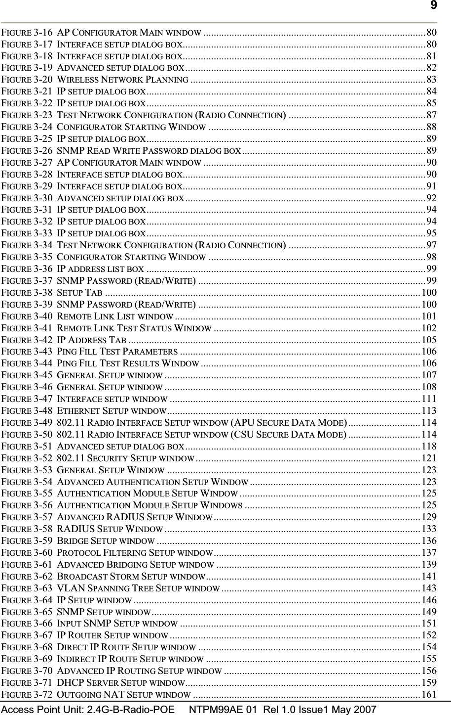
![32 Access Point Unit: 2.4G-B-Radio-POE NTPM99AE 01 Rel 1.0 Issue1 May 2007Figure 2-2 Typical FRESNEL Zone Calculation Example Case I.D: 1 [mile] , where D1=D2=D/2=1/2=0.5 mile F: 2.4 [GHz] R = 72.6 x sqrt (1/ (4x2.4)) [feet] = 23.25 feet (7.07 meter) Re = 73.54 * 0.6 = 13.95 feet (4.242 meter) Case II.D: 1 [mile] , where D1=D/4=0.25 mile, D2=3*D/4=0.75 mile F: 2.4 [GHz] R = 72.6 x sqrt ((0.25*0.75)/ (4x2.4)) [feet] = 20 feet (6 meter) Re = 20 * 0.6 = 12 feet (3.6 meter)](https://usermanual.wiki/MTI/APU11B01POE/User-Guide-821323-Page-32.png)
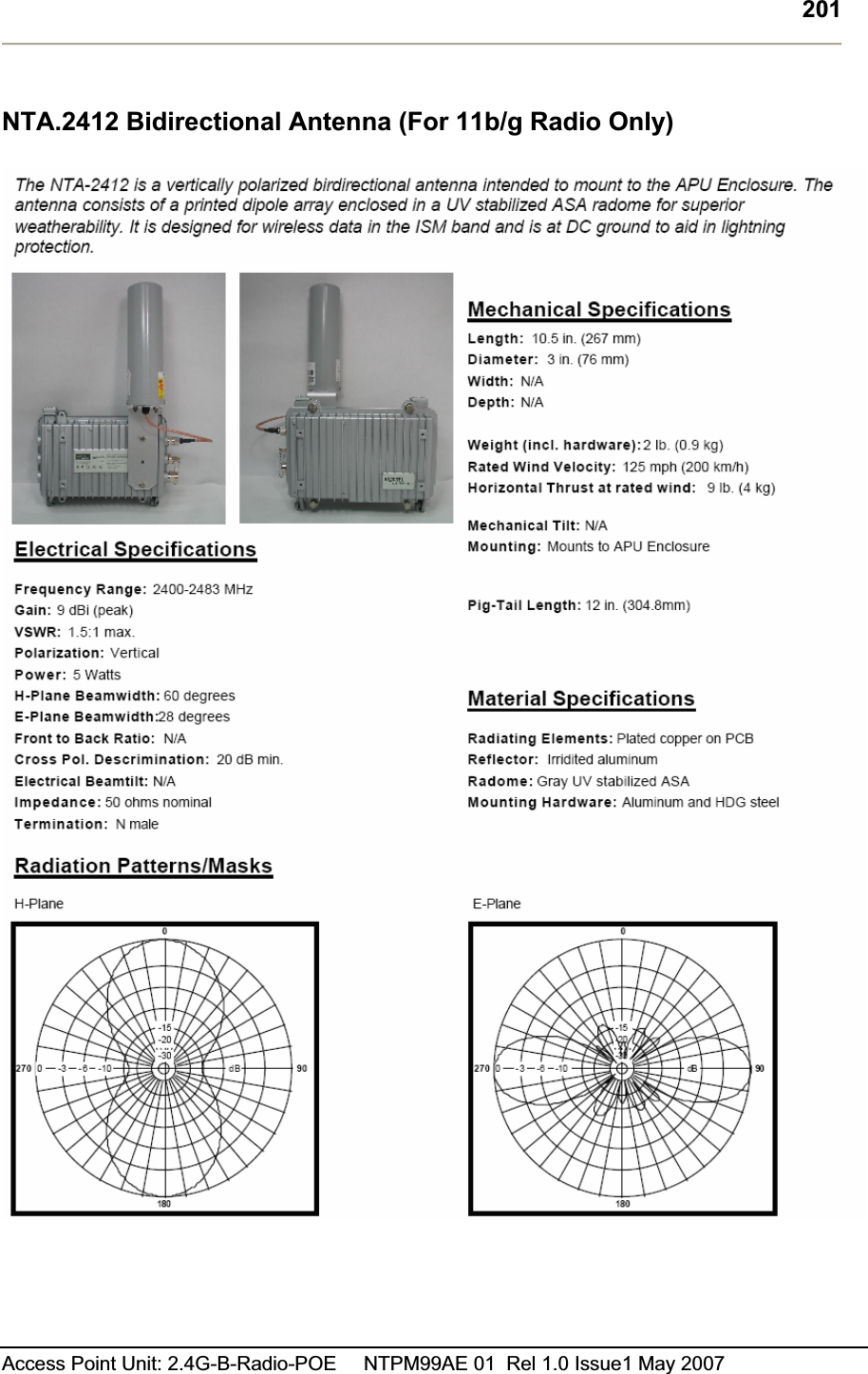
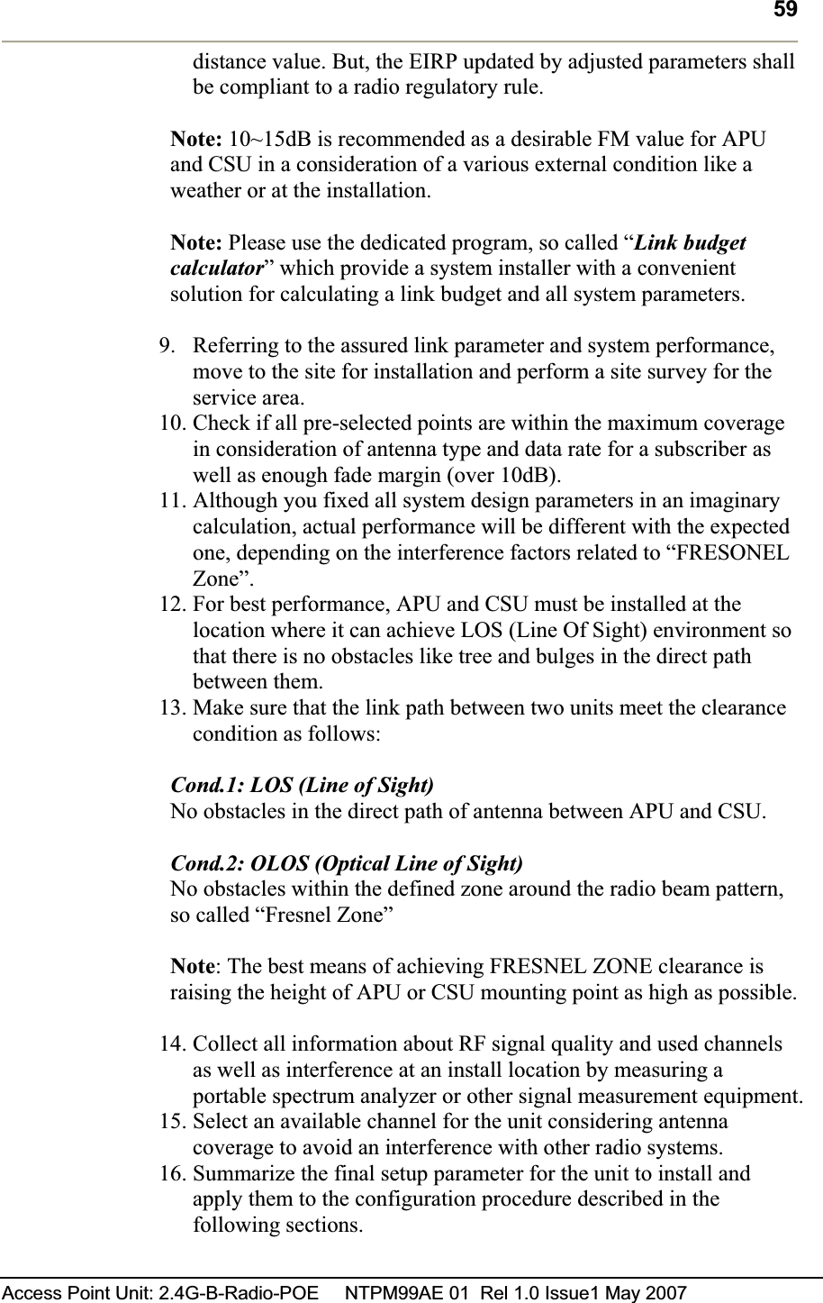
![35Access Point Unit: 2.4G-B-Radio-POE NTPM99AE 01 Rel 1.0 Issue1 May 2007 Link budget and Max Distance Prior to an actual installation, it is prerequisite to predict an arriving signal level at the receiver and determine the fade margin to achieve a system redundancy so that the radio system can be designed for a specific service quality as well as system availability. The system factors affiliated with link budget can be calculated by the formula listed below RSL (Received Signal Level) = Pout + Gtx + Grx – Lct – Lcr - FSL Pout: Transmitter Output Power(Conducted) in dBm Gtx: Transmitter antenna gain in dBi Grx: Receiver antenna gain in dBi Lct: Transmission loss between antenna and Transmitter module in dB Lcr: Transmission loss between antenna and Receiver module in dB FSL: Free space loss attenuation in dB * FSL = 92.4 + 20Log(F) + 20Log(Rkm) [MKS] = 36.56 + 20Log(F) + 20Log(Rmile) [Mile] where, F: Frequency (MHz), R: Range (Km/mile)FM(Fade Margin) = RSL – (Receiver Sensitivity Level) Figure 2-5 Link budget and Fade margin](https://usermanual.wiki/MTI/APU11B01POE/User-Guide-821323-Page-35.png)

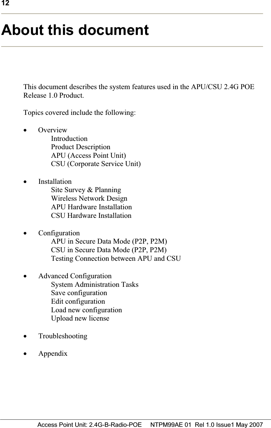
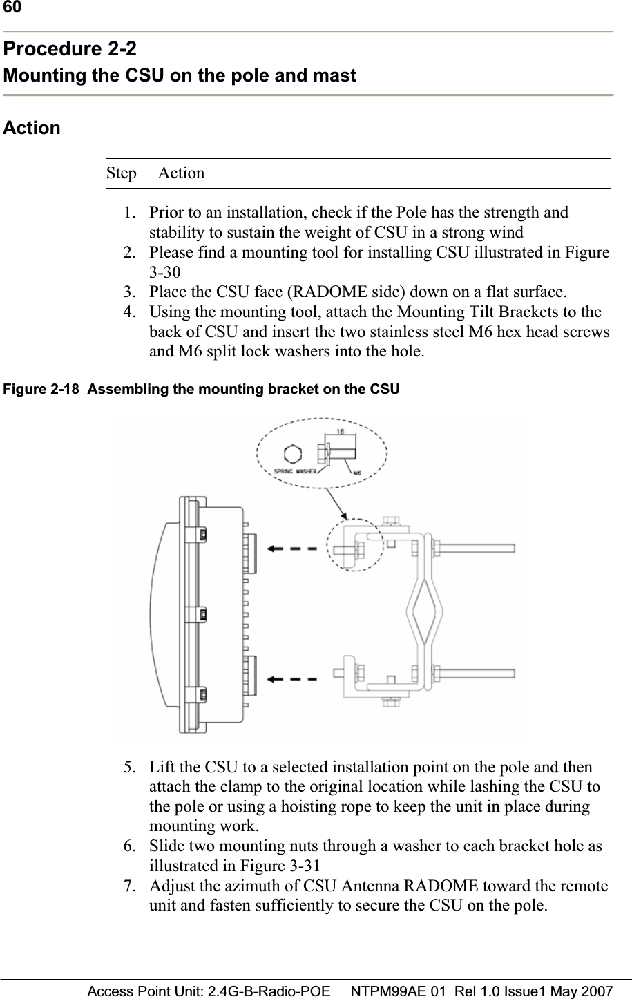
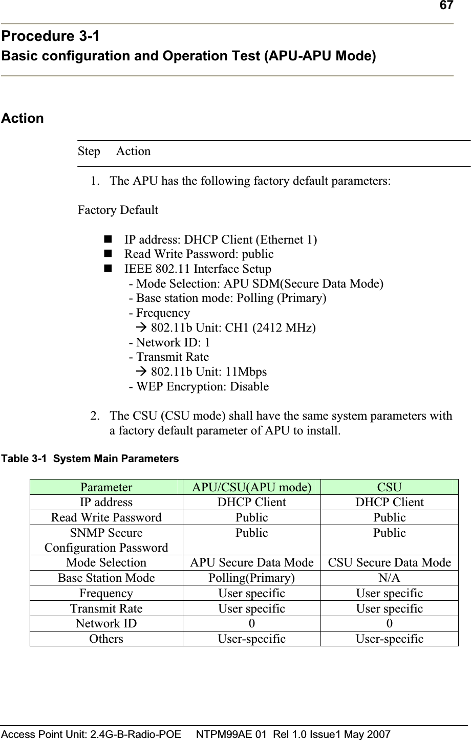
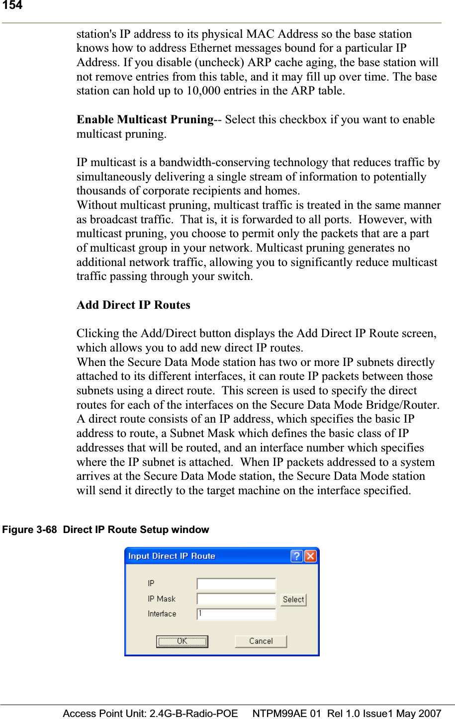
![53Access Point Unit: 2.4G-B-Radio-POE NTPM99AE 01 Rel 1.0 Issue1 May 2007 Procedure 1-4Connecting to the APU ActionStep Action 1. Constructing the CAT5 cable connection with the outdoor type RJ-45 connector packaged in the box following the instruction [Step 1 ~ Step 9] illustrated in Figure 2-40. Note: It is recommended to use a shielded cable like S-FTP(Foiled Twisted Pair) or STP (Shielded Twisted Pair) in which wire pairs are covered with overall shield material to prevent EMI effects to or from the near electronic devices or facilities.Note: The cable from APU to POE Injector and from POE Injector to CPE (PC) should be a straight-through cable.Figure 2-15 Constructing the outdoor POE input jack to APU](https://usermanual.wiki/MTI/APU11B01POE/User-Guide-821323-Page-53.png)
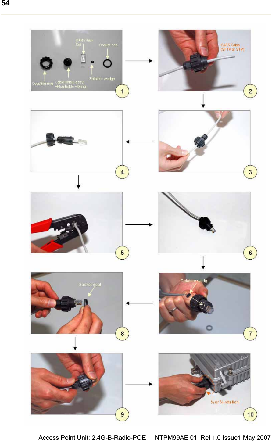
![55Access Point Unit: 2.4G-B-Radio-POE NTPM99AE 01 Rel 1.0 Issue1 May 2007 2. Plug the outdoor RJ-45 Jack to the POE connector on APU enclosure and then secure the coupling ring by rotating it as a clock-wise direction. [Step 10]3. Connect the opposite end of cable to POE Injector prepared4. Cover the connectors with black self amalgamating tape or shrink wrap tubing to ensure a waterproof seal. This is the most useful and meaningful step in the installation. If this procedure is disregarded or done insufficiently, an unexpected system fault could occur in a normal operation and affect on the system performance factor relevant to the long term reliability. WHEN INSTALLING THE UNIT, CHOOSE A LOCATION THAT PROVIDES A MINIMUM SEPARATION OF 20 cm FROM ALL PERSONS DURING NORMAL OPERATION.](https://usermanual.wiki/MTI/APU11B01POE/User-Guide-821323-Page-55.png)
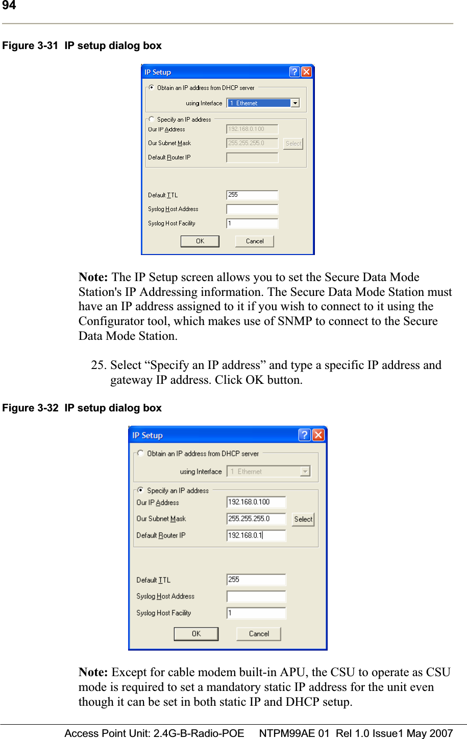
![72 Access Point Unit: 2.4G-B-Radio-POE NTPM99AE 01 Rel 1.0 Issue1 May 200722. The Advanced Setup screen for a Secure Data Mode is shown below.23. Setup all radio parameters including a frequency channel and transmit power referring to the permitted setting value specified in the following tables per radio standard.Figure 3-8 Advanced setup dialog box [802.11b]Frequency Channel 6 2437 MHz1 2412 MHz 7 2442 MHz2 2417 MHz 8 2447 MHz3 2422 MHz 9 2452 MHz4 2427 MHz 10 2457 MHz5 2432 MHz 11 2462 MHzTransmit Rate 11 Mbps 5.5 Mbps 2 Mbps 1 Mbps](https://usermanual.wiki/MTI/APU11B01POE/User-Guide-821323-Page-72.png)
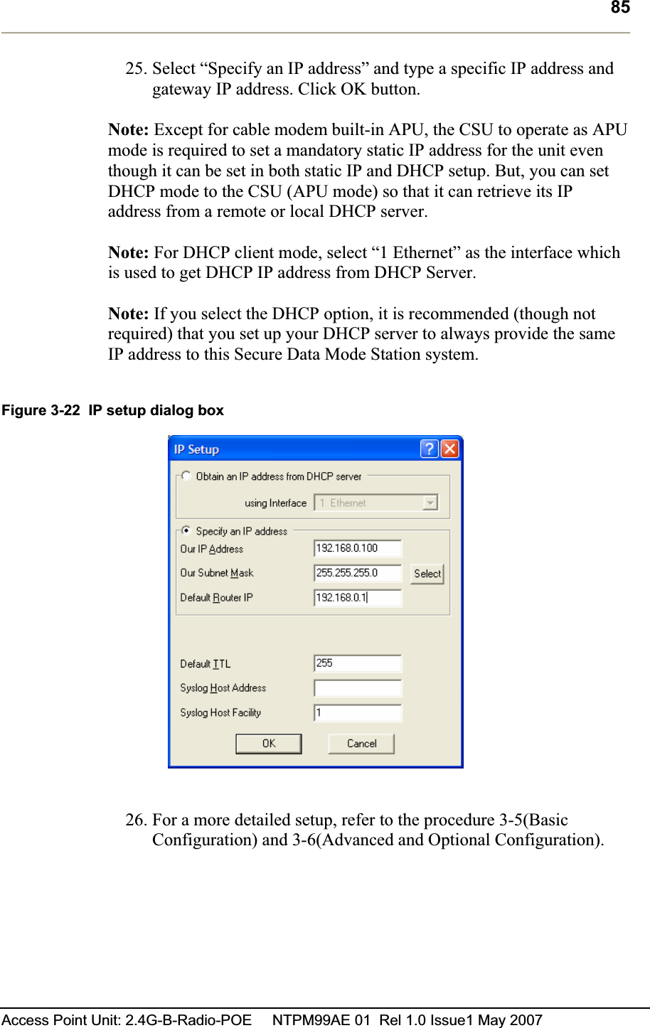
![77Access Point Unit: 2.4G-B-Radio-POE NTPM99AE 01 Rel 1.0 Issue1 May 2007 Figure 3-12 Test Network Configuration (Radio Connection) [Case I] APU to CSU (PTP or PMP) [Case II] CSU to CSU (PTP or PMP)](https://usermanual.wiki/MTI/APU11B01POE/User-Guide-821323-Page-77.png)
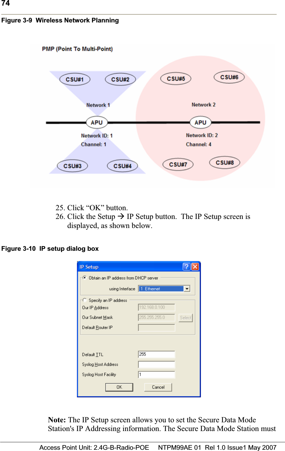
![82 Access Point Unit: 2.4G-B-Radio-POE NTPM99AE 01 Rel 1.0 Issue1 May 2007Figure 3-19 Advanced setup dialog box [802.11b]Frequency Channel 6 2437 MHz1 2412 MHz 7 2442 MHz2 2417 MHz 8 2447 MHz3 2422 MHz 9 2452 MHz4 2427 MHz 10 2457 MHz5 2432 MHz 11 2462 MHzTransmit Rate 11 Mbps 5.5 Mbps 2 Mbps 1 Mbps Transmit Power Antenna Gain Maximum 50%25%12.5%Maximum allowable antennaGain(CSU/11B): 12dBi](https://usermanual.wiki/MTI/APU11B01POE/User-Guide-821323-Page-82.png)
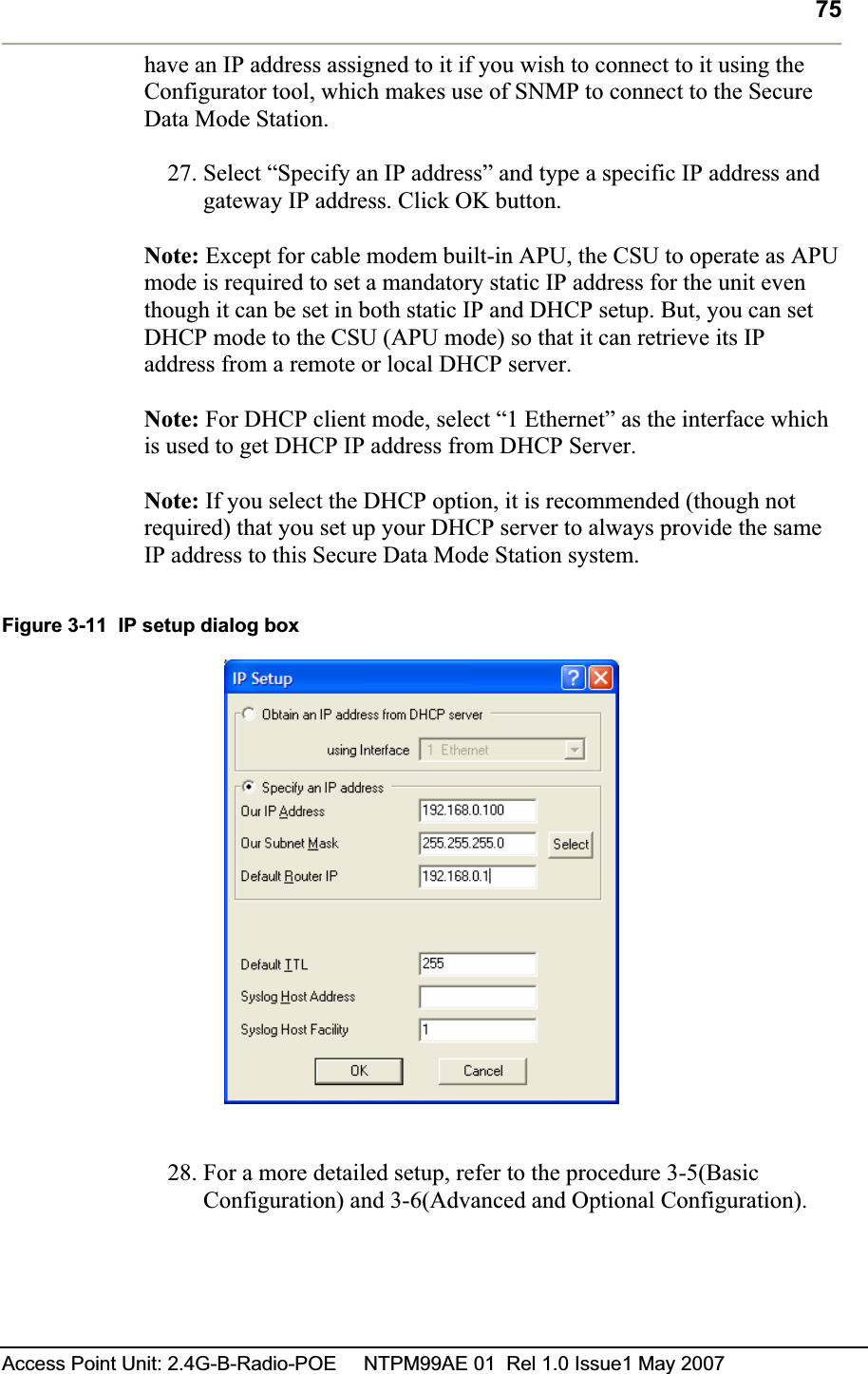
![87Access Point Unit: 2.4G-B-Radio-POE NTPM99AE 01 Rel 1.0 Issue1 May 2007 Figure 3-23 Test Network Configuration (Radio Connection) [Case I] APU to CSU (PTP or PMP) [Case II] CSU to CSU (PTP or PMP)](https://usermanual.wiki/MTI/APU11B01POE/User-Guide-821323-Page-87.png)
![92 Access Point Unit: 2.4G-B-Radio-POE NTPM99AE 01 Rel 1.0 Issue1 May 2007Figure 3-30 Advanced setup dialog box [802.11b]Frequency Channel 6 2437 MHz1 2412 MHz 7 2442 MHz2 2417 MHz 8 2447 MHz3 2422 MHz 9 2452 MHz4 2427 MHz 10 2457 MHz5 2432 MHz 11 2462 MHzTransmit Rate 11 Mbps 5.5 Mbps 2 Mbps 1 Mbps Transmit Power Antenna Gain Maximum 50%25%12.5%Maximum allowable antennaGain(CSU/11B): 12dBi Caution:Do not use any other antennas exceeding the allowed maximum antenna gain value (12dBi) except as the built-in type of antenna (ET-PR12) designated in Appendix B (Antenna) in case you select 802.11b/g mode as operation radio standard.](https://usermanual.wiki/MTI/APU11B01POE/User-Guide-821323-Page-92.png)
![97Access Point Unit: 2.4G-B-Radio-POE NTPM99AE 01 Rel 1.0 Issue1 May 2007 Figure 3-34 Test Network Configuration (Radio Connection) [Case I] APU to CSU (PTP or PMP) [Case II] CSU to CSU (PTP or PMP)](https://usermanual.wiki/MTI/APU11B01POE/User-Guide-821323-Page-97.png)
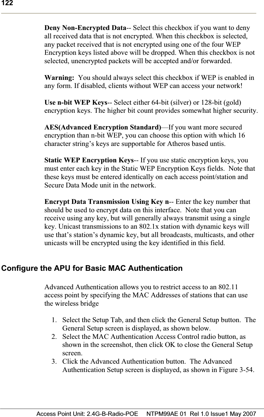
![118 Access Point Unit: 2.4G-B-Radio-POE NTPM99AE 01 Rel 1.0 Issue1 May 2007Enable Signal Quality Front Panel Display-- On units that have a front panel display that is capable of displaying the signal quality, selecting this checkbox will enable the signal quality display. Deny Inter-Client Traffic on this Interface-- Select this checkbox if you wish to prevent wireless stations from sending packets to each other directly. Usually, the AP will repeat station-to-station traffic and will not send it to the bridge and firewall filters. This is because bridging routines historically work between physical interfaces only. An Ethernet packet sent between two Ethernet hosts on the same Ethernet subnet will automatically be seen by the destination host. With wireless, the packet must be repeated by the AP. This turns off the AP’s packet repeating code. Secure Data Mode Advanced Setup Clicking the Advanced Button on the 802.11 Setup screen displays the 802.11 advanced Setup screen, which allows you to configure more options related to the setup of your 802.11 network device. The appearance of the 802.11 Setup screen varies depending on which options are set on the 802.11 Setup screen. The 802.11 Advanced Setup screen for a Secure Data Mode Base Station is shown below. Figure 3-51 Advanced setup dialog box [802.11b]](https://usermanual.wiki/MTI/APU11B01POE/User-Guide-821323-Page-118.png)
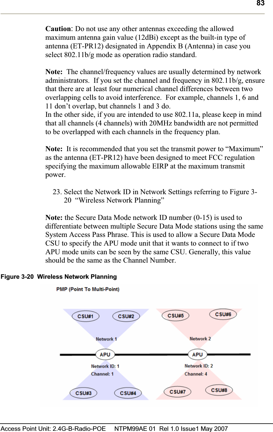
![119Access Point Unit: 2.4G-B-Radio-POE NTPM99AE 01 Rel 1.0 Issue1 May 2007 Network ID-- Enter the Secure Data Mode network ID number (0-15) used to differentiate between multiple Secure Data Mode stations using the same System Access Pass Phrase. This is used to allow a Secure Data Mode satellite to specify the Base Station it wants to connect to if two base stations can be seen by the same satellite. Generally, this value should be the same as the Channel Number. 802.11 Frequency Setup-- Click the Frequency button on the 802.11 Setup screen displays the 802.11 Frequency Setup screens, which allows you to set the Frequency Channel for your 802.11 radio card. The 802.11 Frequency Setup screen is used to change the channel and frequency for one of the remote devices on your network. Note that this screen is only accessible if you have identified remote devices in your network. If all devices are in your local network, then the Frequency Setup screen is unavailable. Channel/Frequency-- Select the channel and frequency for the remote device from the drop-down list. See Frequency Channels for a more detailed explanation of the frequency channels. [802.11b]Frequency Channel 6 2437 MHz 1 2412 MHz 7 2442 MHz 2 2417 MHz 8 2447 MHz 3 2422 MHz 9 2452 MHz 4 2427 MHz 10 2457 MHz 5 2432 MHz 11 2462 MHz Radio Transmit Rate-- Select the radio bit rate used to transmit. Your choices are: [802.11b]Transmit Rate 11 Mbps 5.5 Mbps 2 Mbps 1 Mbps A lower signal will increase the noise. In essence, the poorer the signal-to-noise ratio, the lower this rate should be set. Note: The transmit rate affects only the transmissions made by this station.](https://usermanual.wiki/MTI/APU11B01POE/User-Guide-821323-Page-119.png)
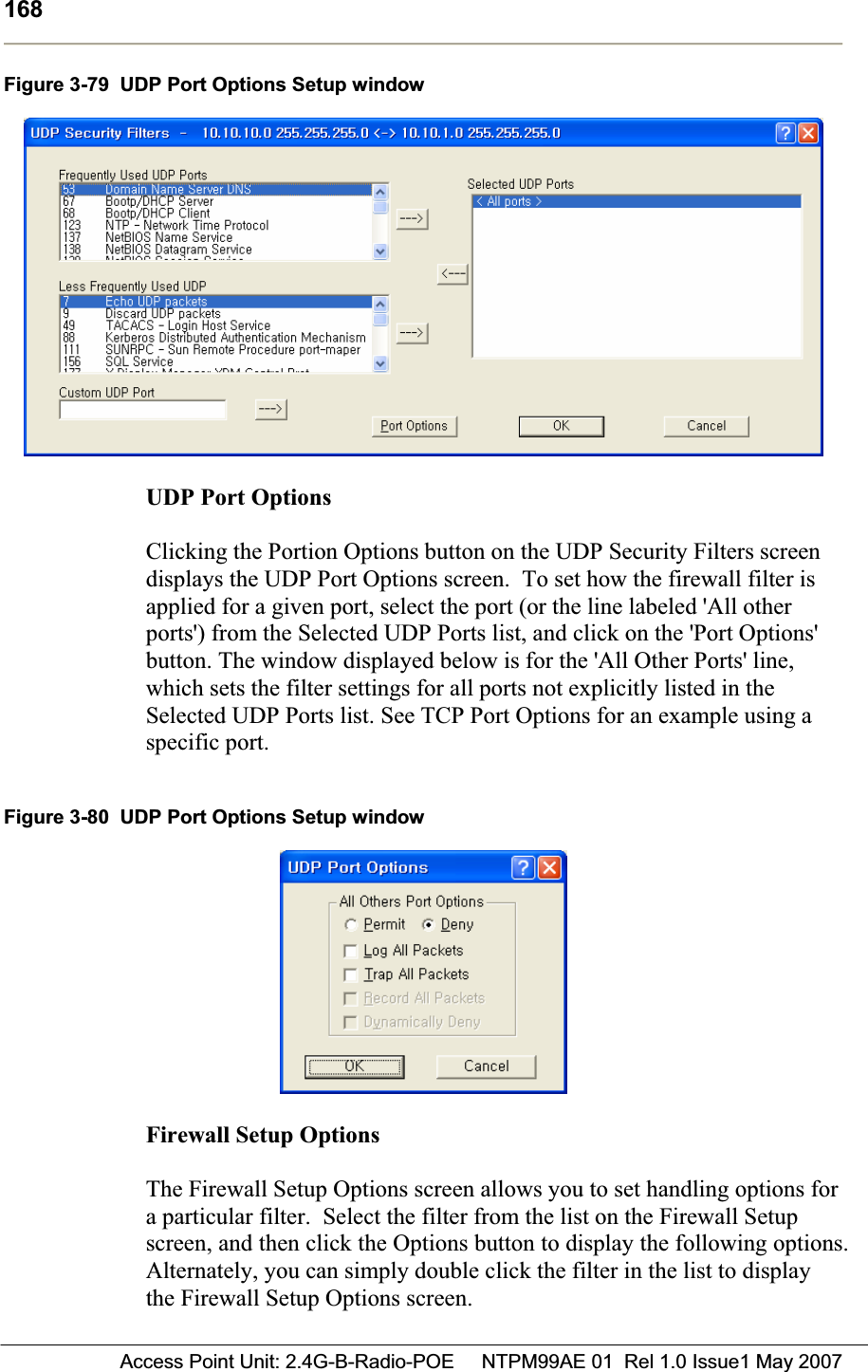
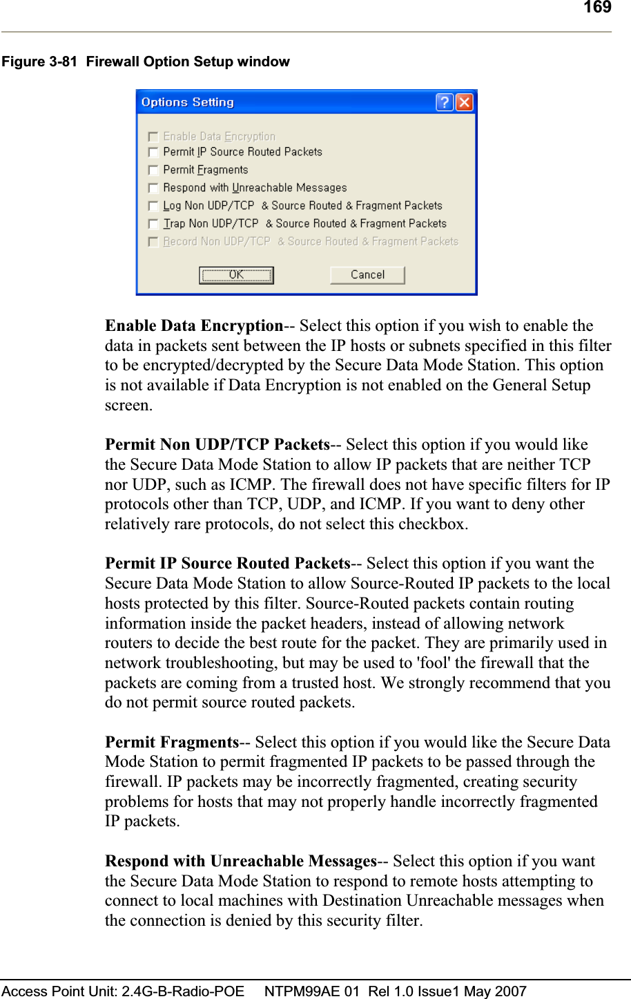
![170 Access Point Unit: 2.4G-B-Radio-POE NTPM99AE 01 Rel 1.0 Issue1 May 2007Log Non UDP/TCP & Source Routed & Fragment Packets-- Select this option if you want to log to the syslog for all packets that are not UDP/TCP, are source-routed, or are fragmented. Trap Non UDP/TCP & Source Routed & Fragment Packets-- Select this option if you want the Secure Data Mode Station to SNMP Trap messages whenever a non-TCP or non-UDP, Source Routed, or Fragmented IP packet is received by the Secure Data Mode Station. SNMP Traps are sent to the SNMP Trap Host specified in SNMP Setup. Record Non UDP/TCP & Source Routed & Fragment Packets--Select this option if you want the Secure Data Mode Station to record all packets that are not UDP/TCP, are source-routed, or are fragmented. IP Protocol FiltersClicking the IP Protocols button displays the IP Protocol Filters screen, which allows you to set the IP protocols to which a given filter will be applied. Select the filter you want to modify on the Firewall Setup screen, and click the IP Protocols button. Less Frequently Used IP Protocols-- This list displays some of the less commonly used protocols that run over IP If you wish to filter one of these protocols, select it and click the [ -> ] button. Then set the action to take using the Protocol Options button. Selected IP Protocols-- Select one of the protocols added to the list and then click the Protocol Options button to set the action for this protocol.Select “All Protocols" or "All Other Protocols" to set a default action when a packet is received from a protocol for which no action has been defined.Figure 3-82 IP Protocol Filter Setup window](https://usermanual.wiki/MTI/APU11B01POE/User-Guide-821323-Page-170.png)
![171Access Point Unit: 2.4G-B-Radio-POE NTPM99AE 01 Rel 1.0 Issue1 May 2007 Custom IP Protocol-- If you wish to explicitly allow or deny access to a given IP protocol not listed in the two panels above, you can add that protocol to the list by simply typing it in the Custom IP Protocol field and clicking on the right arrow button [->] next to the text field. You do not need to add a protocol to the list unless you have specific requirements for that particular protocol. IP Protocol OptionsClicking the Protocol Options button displays the IP Protocol Options screen, which allows you to define an action to take when data using that protocol is sent or received. When you select a protocol to filter, you will need to define an action to take when data using that protocol is sent or received. Initially, you will need to indicate whether you wish to permit or deny that protocol. In addition, you can optionally choose to log, trap, or record all packets, and to dynamically deny all other protocols.Figure 3-83 IP Protocol Option Setup window Permit All Other Protocols Button-- Select this button if you wish to permit all other protocols. Deny All Other Protocols Button-- Select this button if you wish to deny all other protocols. Log All Packets-- Select this checkbox if you wish to log all packets. Trap All Packets-- Select this checkbox if you wish to trap all packets. Record All Packets-- Select this checkbox if you wish to record all packets.Dynamically Deny All Other Protocols-- Select this checkbox if you wish to dynamically deny all other protocols.](https://usermanual.wiki/MTI/APU11B01POE/User-Guide-821323-Page-171.png)
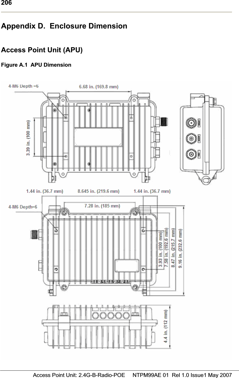
![194 Access Point Unit: 2.4G-B-Radio-POE NTPM99AE 01 Rel 1.0 Issue1 May 2007Appendix A. Specification Access Point Unit (APU) Physical Dimension z300(W) * 232.6(L) * 112(D) [Unit: mm] z11.81 (W) * 9.157 (L) * 4.40 (D) [Unit: inch] Weight(without antenna): 6.661 lbs(<7 lbs), 3.0 Kg Enclosure: Strong Aluminum alloy case –Steel with anodizing coating surface(Waterproof, EMI protection, Vibration Robust) Power consumption: Max 6W(3.3Vdc/1.5A) System elements: Access Point, POE PD(Power Device) Interface Ports: Ethernet Port(CAT5/POE/802.3af) Pole mountable and External Built-in type Antenna Wireless LANWireless LAN standard: IEEE 802.11b Frequency Band & Channel 2.4~2.4835GHz(ISM)Table A.1 802.11b(ISM) channel assignment Frequency Channel 6 2437 MHz 1 2412 MHz 7 2442 MHz 2 2417 MHz 8 2447 MHz 3 2422 MHz 9 2452 MHz 4 2427 MHz 10 2457 MHz 5 2432 MHz 11 2462 MHz Modulation: DSSS(DBPSK,DQPSK,CCK) Data rate: 1Mbps, 2Mbps, 5.5Mbps, 11Mbps Power adjustment (4 steps): 100%(Max), 50%, 25%, 12.5% Maximum Transmit Power(Radio)](https://usermanual.wiki/MTI/APU11B01POE/User-Guide-821323-Page-194.png)
![195Access Point Unit: 2.4G-B-Radio-POE NTPM99AE 01 Rel 1.0 Issue1 May 2007 Table A.2 Output power table [dBm] in 802.11b CH 2412 MHz 2447MHz 2462 MHz Remark1 Mbps 12 12.2 12.3 +/-1.5dB2 Mbps 11.2 11.4 11.5 +/-1.5dB5.5 Mbps 10.2 10.4 10.5 +/-1.5dB11 Mbps 9.7 9.9 10.0 +/-1.5dBMax EIRP [dBm] for PMP topology Table A.3 Output power table [dBm] in 802.11b Mode NTA-2407 NTA-2412 NTA-2400 EIRP Limit 11b 27 22 20 36 dBm(4W) Receiver sensitivity: (Normal Temperature) Table A.4 Receiver Sensitivity table (802.11b) Data Rate Receiver Sensitivity 1 Mbps -83dBm 2 Mbps -86dBm 5.5 Mbps -89dBm 11 Mbps -92dBm SoftwareFirmware : APU Secure Data Mode (Base Station) Wireless Service Protocol : Secure Data Mode, Dynamic Polling MAC access control – 32 local MAC Address Table (SDM mode)* Standard RADIUS server support Wired Equivalent Privacy encryption - 64, 128, AES Firewall (ICMP/UDP/TCP/IP Protocol Filtering) Layer 2 Protocol Filtering BOOTP/DHCP (Server, Relay, Client), Static IP NAT (Incoming/Outgoing) Routing Protocol (RIP v2, Static)Restriction of Broadcast Storm SNMP v1, Software upgrade via TFTP (only applicable to cable modem) GUI Program : Windows Based Throughput Analysis: Ping Fill Radio Performance Testing Tool: Antenna Alignment Remote Statistics Monitoring SNMP Traps MIB II](https://usermanual.wiki/MTI/APU11B01POE/User-Guide-821323-Page-195.png)
![197Access Point Unit: 2.4G-B-Radio-POE NTPM99AE 01 Rel 1.0 Issue1 May 2007 Corporate Service Unit (CSU) Physical Dimension 180(W) * 180(L) *81(D) [Unit: mm] 180(W) * 239(L) *81(D) with the EMI cap [Unit: inch] Weight(without antenna): 2.8659 lbs(1.30 Kg) with the mounting bracket kit Enclosure: Gray UV Stabilized ASA(Cover), Aluminum and HDG Steel(Body) Power consumption: Max 6W(3.3Vdc/1.5A) System elements: Access Point, POE PD(Power Device) Interface Ports: Ethernet Port(CAT5/POE/802.3af) Pole mountable and Built-in type Antenna Wireless LANWireless LAN standard: IEEE 802.11a/b/g Frequency Band & Channel 2.4~2.4835GHz(ISM)Table A.5 802.11b/g(ISM) channel assignment Frequency Channel 6 2437 MHz 1 2412 MHz 7 2442 MHz 2 2417 MHz 8 2447 MHz 3 2422 MHz 9 2452 MHz 4 2427 MHz 10 2457 MHz 5 2432 MHz 11 2462 MHz Modulation: DSSS(DBPSK,DQPSK,CCK), OFDM(16QAM, QPSK,BPSK) Data rate: 1Mbps, 2Mbps, 5.5Mbps, 11Mbps, 6Mbps, 9Mbps, 12Mbps, 18Mbps, 24Mbps, 36Mbps Power adjustment (4 steps): 100%(Max), 50%, 25%, 12.5%](https://usermanual.wiki/MTI/APU11B01POE/User-Guide-821323-Page-197.png)
![198 Access Point Unit: 2.4G-B-Radio-POE NTPM99AE 01 Rel 1.0 Issue1 May 2007Maximum Transmit Power(Radio) Table A.6 Output power table [dBm] in 802.11b CH 2412 MHz 2447MHz 2462 MHz Remark1 Mbps 12 12.2 12.3 +/-1.5dB2 Mbps 11.2 11.4 11.5 +/-1.5dB5.5 Mbps 10.2 10.4 10.5 +/-1.5dB11 Mbps 9.7 9.9 10.0 +/-1.5dBMax EIRP [dBm] for PMP topology - 802.11b with 12dBi antenna (ET-PR12): 25 dBm Receive sensitivity: (Normal Temperature) Table A.7 Receiver Sensitivity table (802.11b) Data Rate Receiver Sensitivity 1 Mbps -93dBm 2 Mbps -92dBm 5.5 Mbps -91dBm 11 Mbps -87dBm SoftwareFirmware : APU / CSU Secure Data Mode (Base Station, Satellite) Wireless Service Protocol : Secure Data Mode MAC access control – 32 local MAC Address Table (SDM mode)* Standard RADIUS server support Wired Equivalent Privacy encryption - 64, 128, AES Firewall (ICMP/UDP/TCP/IP Protocol Filtering) Layer 2 Protocol Filtering BOOTP/DHCP (Server, Relay, Client), Static IP NAT (Incoming/Outgoing) Routing Protocol (RIP v2, Static)Restriction of Broadcast Storm SNMP v1, Software upgrade via TFTP (only applicable to cable modem) GUI Program : Windows Based Throughput Analysis: Ping Fill Radio Performance Testing Tool: Antenna Alignment Remote Statistics Monitoring SNMP Traps MIB II](https://usermanual.wiki/MTI/APU11B01POE/User-Guide-821323-Page-198.png)