Manual

Access Point Unit (APU) 802.11b POE
Corporate Service Unit (CSU) 802.11b POE
User Guide
Standard Release 1.0 Issue 1 May 2007
What’s inside?
About this document
Overview
Installation
Configuration
Administration
Troubleshooting
Appendix
NTPM99AE / NTPM99BC

2

3
Copyright © 2007 MTI co. ltd
All rights reserved. May 2007.
No part of this publication may be reproduced, stored in a retrieval system, or transmitted in any form or
by any means, whether electronic, mechanical, photocopying, recording or otherwise without the prior
writing of the publisher.
MTI and the MTI logo are trademarks of MTI co. ltd.
Multi-Region Product Documentation
This document may describe features that are not available in your region due to local regulations.

4
Access Point Unit: 2.4G-B-Radio-POE NTPM99AE 01 Rel 1.0 Issue1 May 2007
Publication history
May 2007
Issue 1. Issued for APU(Access Point Unit) & CSU(Corporate
Service Unit)

5
Access Point Unit: 2.4G-B-Radio-POE NTPM99AE 01 Rel 1.0 Issue1 May 2007

6
Access Point Unit: 2.4G-B-Radio-POE NTPM99AE 01 Rel 1.0 Issue1 May 2007
Contents
PUBLICATION HISTORY.....................................................................................4G
CONTENTS ..............................................................................................................6G
LIST OF FIGURES.................................................................................................. 8G
LIST OF TABLES..................................................................................................11G
ABOUT THIS DOCUMENT.................................................................................12G
AUDIENCE............................................................................................................13G
LIST OF ABBREVIATIONS .....................................................................................13G
SAFETY AND CONFORMANCE GUIDELINES..............................................16G
SAFETY PRECAUTIONS .........................................................................................17G
RADIO REGULATION CONFORMANCE ..................................................................18G
OVERVIEW ...........................................................................................................19G
INTRODUCTION ....................................................................................................19G
PRODUCT DESCRIPTION .......................................................................................21G
APU (ACCESS POINT UNIT).................................................................................21G
CSU (CORPORATE SERVICE UNIT) ......................................................................24G
INSTALLATION....................................................................................................28G
PRE-STUDY FOR...................................................................................................30G
WIRELESS NETWORK DESIGN AND DEPLOYMENT ...............................................30G
APU INSTALLATION & CONFIGURATION ..................................................42G
PROCEDURE 1-1 ...................................................................................................43G
PROCEDURE 1-2 ...................................................................................................46G
PROCEDURE 1-3 ...................................................................................................51G
PROCEDURE 1-5 ...................................................................................................56G
CSU INSTALLATION & CONFIGURATION...................................................57G
PROCEDURE 2-1 ...................................................................................................58G
PROCEDURE 2-2 ...................................................................................................60G
PROCEDURE 2-3 ...................................................................................................62G
CONFIGURATION ...............................................................................................66G
PROCEDURE 3-1 ...................................................................................................67G
PROCEDURE 3-3 ...................................................................................................86G
PROCEDURE 3-4 ...................................................................................................96G
PROCEDURE 3-5 .................................................................................................105G
PROCEDURE 3-6 .................................................................................................107G
PROCEDURE 3-7 .................................................................................................136G
ADMINISTRATION............................................................................................177G
SAVING CONFIGURATION ...................................................................................178G
LOADING NEW CONFIGURATION.........................................................................179G
UPLOADING SOFTWARE .....................................................................................180G
REBOOT A REMOTE STATION(APU AND CSU) ..................................................187G
TROUBLESHOOTING.......................................................................................188G

7
Access Point Unit: 2.4G-B-Radio-POE NTPM99AE 01 Rel 1.0 Issue1 May 2007
APPENDIX ...........................................................................................................193G
APPENDIX A. SPECIFICATION.............................................................................194G
APPENDIX B. ANTENNA .....................................................................................200G
APPENDIX C. LINK BUDGET AND DISTANCE ......................................................203G
APPENDIX D. ENCLOSURE DIMENSION..............................................................206G

8
Access Point Unit: 2.4G-B-Radio-POE NTPM99AE 01 Rel 1.0 Issue1 May 2007
List of Figures
FIGURE 1-1 APU/CSU 802.11BPOE SERVICE CONCEPT DIAGRAM ..........................................................20G
FIGURE 1-2 APU 802.11ABG POE..............................................................................................................21G
FIGURE 1-3 APU (TOP HEAD).....................................................................................................................22G
FIGURE 1-4 APU (BOTTOM).......................................................................................................................22G
FIGURE 1-5 APU (INNER PANEL)................................................................................................................23G
FIGURE 1-8 CSU 802.11BPOE PACKAGE COMPONENTS ............................................................................24G
FIGURE 1-9 CSU 802.11BPOE(BOTTOM)..................................................................................................25G
FIGURE 1-10 CSU 802.11BPOE (FRONT)...................................................................................................25G
FIGURE 1-11 CSU 802.11BPOE (BACK) ....................................................................................................26G
FIGURE 1-12 CSU 802.11BPOE .................................................................................................................26G
FIGURE 2-1 FRESNEL ZONE .....................................................................................................................31G
FIGURE 2-2 TYPICAL FRESNEL ZONE.......................................................................................................32G
FIGURE 2-3 EARTH BULGE EFFECT (BEFORE RAISING THE ANTENNA) ........................................................33G
FIGURE 2-4 EARTH BULGE EFFECT (AFTER RAISING THE ANTENNA) ..........................................................34G
FIGURE 2-5 LINK BUDGET AND FADE MARGIN............................................................................................35G
FIGURE 2-6 DIRECTIONAL ANTENNA CONCEPT (FLAT PANEL ANTENNA): CASE I (PARALLEL TYPE).......38G
FIGURE 2-7 DIRECTIONAL ANTENNA CONCEPT (FLAT PANEL ANTENNA): CASE II (CROSS TYPE)............39G
FIGURE 2-8 OMNI-DIRECTIONAL ANTENNA CONCEPT.................................................................................40G
FIGURE 2-9 BI-DIRECTIONAL ANTENNA CONCEPT ......................................................................................40G
FIGURE 2-10 APU INSTALLATION CONCEPT ..............................................................................................42G
FIGURE 2-11 NTA-2407 ANTENNA ASSEMBLY..........................................................................................47G
FIGURE 2-12 NTA-2400 ANTENNA ASSEMBLY..........................................................................................48G
FIGURE 2-13 NTA-2412 ANTENNA ASSEMBLY..........................................................................................50G
FIGURE 2-14 ANTENNA MOUNTING WITH A BRACKET ................................................................................51G
FIGURE 2-15 CONSTRUCTING THE OUTDOOR POE INPUT JACK TO APU.....................................................53G
FIGURE 2-16 ASSEMBLING THE GROUNDING BOLT AND WIRE.....................................................................56G
FIGURE 2-17 CSU INSTALLATION CONCEPT ON USER’S FACILITY.............................................................57G
FIGURE 2-18 ASSEMBLING THE MOUNTING BRACKET ON THE CSU............................................................60G
FIGURE 2-19 ASSEMBLING THE MOUNTING BRACKET WITH A INSTALLATION TOOL ...................................61G
FIGURE 2-20 CSU POLE MOUNTING AND ANTENNA TILTING ....................................................................61G
FIGURE 2-21 CONNECTING ETHERNET CABLE TO CSU AND SECURING THE EMI CAP...............................62G
FIGURE 2-22 PROTECTING EMI CAP AND SHIELDED CABLE WITH TAPE OR SHRINK WRAP TUBING ...........63G
FIGURE 2-23 CONNECTING THE GROUND WIRE TO THE GROUND POINT ......................................................63G
FIGURE 2-24 ADJUSTING THE TILT AND HEIGHT .........................................................................................64G
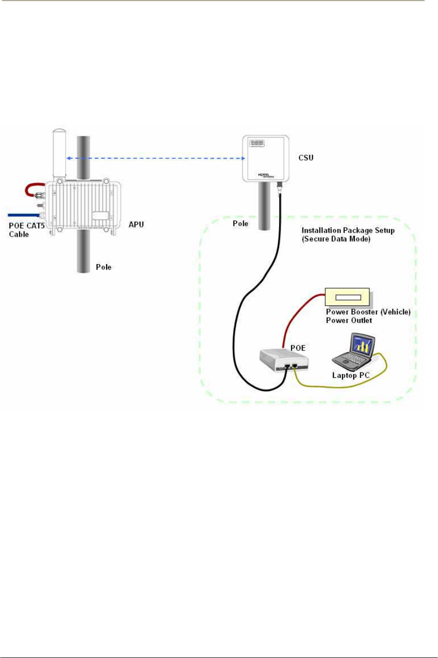
FIGURE 2-25 CONNECTING CSU AND USER PC BY AN ETHERNET CABLE THOUGH POE INJECTOR ...........64G
FIGURE 3-1 TEST NETWORK CONFIGURATION (RADIO CONNECTION) .......................................................68G
FIGURE 3-2 CONFIGURATOR STARTING WINDOW ......................................................................................69G
FIGURE 3-3 IP SETUP DIALOG BOX..............................................................................................................69G
FIGURE 3-4 SNMP READ WRITE PASSWORD DIALOG BOX .........................................................................70G
FIGURE 3-5 AP CONFIGURATOR MAIN WINDOW ........................................................................................70G
FIGURE 3-6 INTERFACE SETUP DIALOG BOX................................................................................................71G
FIGURE 3-7 INTERFACE SETUP DIALOG BOX................................................................................................71G
FIGURE 3-8 ADVANCED SETUP DIALOG BOX ...............................................................................................72G
FIGURE 3-9 WIRELESS NETWORK PLANNING .............................................................................................74G
FIGURE 3-10 IP SETUP DIALOG BOX............................................................................................................74G
FIGURE 3-11 IP SETUP DIALOG BOX............................................................................................................75G
FIGURE 3-12 TEST NETWORK CONFIGURATION (RADIO CONNECTION) .....................................................77G
FIGURE 3-13 CONFIGURATOR STARTING WINDOW ....................................................................................78G
FIGURE 3-14 IP SETUP DIALOG BOX............................................................................................................79G
FIGURE 3-15 SNMP READ WRITE PASSWORD DIALOG BOX .......................................................................79G

9
Access Point Unit: 2.4G-B-Radio-POE NTPM99AE 01 Rel 1.0 Issue1 May 2007
FIGURE 3-16 AP CONFIGURATOR MAIN WINDOW ......................................................................................80G
FIGURE 3-17 INTERFACE SETUP DIALOG BOX..............................................................................................80G
FIGURE 3-18 INTERFACE SETUP DIALOG BOX..............................................................................................81G
FIGURE 3-19 ADVANCED SETUP DIALOG BOX.............................................................................................82G
FIGURE 3-20 WIRELESS NETWORK PLANNING ...........................................................................................83G
FIGURE 3-21 IP SETUP DIALOG BOX............................................................................................................84G
FIGURE 3-22 IP SETUP DIALOG BOX............................................................................................................85G
FIGURE 3-23 TEST NETWORK CONFIGURATION (RADIO CONNECTION) .....................................................87G
FIGURE 3-24 CONFIGURATOR STARTING WINDOW ....................................................................................88G
FIGURE 3-25 IP SETUP DIALOG BOX............................................................................................................89G
FIGURE 3-26 SNMP READ WRITE PASSWORD DIALOG BOX .......................................................................89G
FIGURE 3-27 AP CONFIGURATOR MAIN WINDOW ......................................................................................90G
FIGURE 3-28 INTERFACE SETUP DIALOG BOX..............................................................................................90G
FIGURE 3-29 INTERFACE SETUP DIALOG BOX..............................................................................................91G
FIGURE 3-30 ADVANCED SETUP DIALOG BOX.............................................................................................92G
FIGURE 3-31 IP SETUP DIALOG BOX............................................................................................................94G
FIGURE 3-32 IP SETUP DIALOG BOX............................................................................................................94G
FIGURE 3-33 IP SETUP DIALOG BOX............................................................................................................95G
FIGURE 3-34 TEST NETWORK CONFIGURATION (RADIO CONNECTION) .....................................................97G
FIGURE 3-35 CONFIGURATOR STARTING WINDOW ....................................................................................98G
FIGURE 3-36 IP ADDRESS LIST BOX ............................................................................................................99G
FIGURE 3-37 SNMP PASSWORD (READ/WRITE) ........................................................................................99G
FIGURE 3-38 SETUP TAB ..........................................................................................................................100G
FIGURE 3-39 SNMP PASSWORD (READ/WRITE) ......................................................................................100G
FIGURE 3-40 REMOTE LINK LIST WINDOW ...............................................................................................101G
FIGURE 3-41 REMOTE LINK TEST STATUS WINDOW ................................................................................102G
FIGURE 3-42 IP ADDRESS TAB .................................................................................................................105G
FIGURE 3-43 PING FILL TEST PARAMETERS .............................................................................................106G
FIGURE 3-44 PING FILL TEST RESULTS WINDOW .....................................................................................106G
FIGURE 3-45 GENERAL SETUP WINDOW ...................................................................................................107G
FIGURE 3-46 GENERAL SETUP WINDOW ...................................................................................................108G
FIGURE 3-47 INTERFACE SETUP WINDOW .................................................................................................111G
FIGURE 3-48 ETHERNET SETUP WINDOW..................................................................................................113G
FIGURE 3-49 802.11 RADIO INTERFACE SETUP WINDOW (APU SECURE DATA MODE)............................114G
FIGURE 3-50 802.11 RADIO INTERFACE SETUP WINDOW (CSU SECURE DATA MODE) ............................114G
FIGURE 3-51 ADVANCED SETUP DIALOG BOX...........................................................................................118G
FIGURE 3-52 802.11 SECURITY SETUP WINDOW .......................................................................................121G
FIGURE 3-53 GENERAL SETUP WINDOW ..................................................................................................123G
FIGURE 3-54 ADVANCED AUTHENTICATION SETUP WINDOW ..................................................................123G
FIGURE 3-55 AUTHENTICATION MODULE SETUP WINDOW ......................................................................125G
FIGURE 3-56 AUTHENTICATION MODULE SETUP WINDOWS ....................................................................125G
FIGURE 3-57 ADVANCED RADIUS SETUP WINDOW ................................................................................129G
FIGURE 3-58 RADIUS SETUP WINDOW ...................................................................................................133G
FIGURE 3-59 BRIDGE SETUP WINDOW ......................................................................................................136G
FIGURE 3-60 PROTOCOL FILTERING SETUP WINDOW................................................................................137G
FIGURE 3-61 ADVANCED BRIDGING SETUP WINDOW ...............................................................................139G
FIGURE 3-62 BROADCAST STORM SETUP WINDOW...................................................................................141G
FIGURE 3-63 VLAN SPANNING TREE SETUP WINDOW .............................................................................143G
FIGURE 3-64 IP SETUP WINDOW ...............................................................................................................146G
FIGURE 3-65 SNMP SETUP WINDOW........................................................................................................149G
FIGURE 3-66 INPUT SNMP SETUP WINDOW .............................................................................................151G
FIGURE 3-67 IP ROUTER SETUP WINDOW .................................................................................................152G
FIGURE 3-68 DIRECT IP ROUTE SETUP WINDOW ......................................................................................154G
FIGURE 3-69 INDIRECT IP ROUTE SETUP WINDOW ...................................................................................155G
FIGURE 3-70 ADVANCED IP ROUTING SETUP WINDOW ............................................................................156G
FIGURE 3-71 DHCP SERVER SETUP WINDOW...........................................................................................159G
FIGURE 3-72 OUTGOING NAT SETUP WINDOW ........................................................................................161G

10
Access Point Unit: 2.4G-B-Radio-POE NTPM99AE 01 Rel 1.0 Issue1 May 2007
FIGURE 3-73 INCOMING NAT SETUP WINDOW .........................................................................................163G
FIGURE 3-74 INPUT IP ADDRESS/PORT (NAT) SETUP WINDOW ................................................................164G
FIGURE 3-75 FIREWALL SETUP WINDOW ..................................................................................................166G
FIGURE 3-76 INPUT IP ADDRESS (FIREWALL)SETUP WINDOW .................................................................166G
FIGURE 3-77 TCP SECURITY FILTER SETUP WINDOW...............................................................................167G
FIGURE 3-78 TCP PORT OPTIONS SETUP WINDOW ...................................................................................167G
FIGURE 3-79 UDP PORT OPTIONS SETUP WINDOW ..................................................................................168G
FIGURE 3-80 UDP PORT OPTIONS SETUP WINDOW ..................................................................................168G
FIGURE 3-81 FIREWALL OPTION SETUP WINDOW .....................................................................................169G
FIGURE 3-82 IP PROTOCOL FILTER SETUP WINDOW .................................................................................170G
FIGURE 3-83 IP PROTOCOL OPTION SETUP WINDOW ................................................................................171G
FIGURE 3-84 OUTGOING ICMP FILTER SETUP WINDOW...........................................................................172G
FIGURE 3-85 INCOMING ICMP FILTER SETUP WINDOW............................................................................174G
FIGURE 3-86 SNMP AUTHENTICATION RECORD SETUP WINDOW ............................................................176G
FIGURE 4-1 SAVE CONFIG MENU .............................................................................................................178G
FIGURE 4-2 CONFIRM SAVE CONFIG WINDOW .........................................................................................178G
FIGURE 4-3 REBOOT MESSAGE DIALOG BOX ...........................................................................................179G
FIGURE 4-4 OPEN CONFIG/BIN FILE MENU ..............................................................................................179G
FIGURE 4-5 OPEN CONFIG FILE WINDOW.................................................................................................180G
FIGURE 4-6 CONFIRM OPEN CONFIG FILE DIALOG BOX ...........................................................................180G
FIGURE 4-7 UPLOAD SOFTWARE MENU....................................................................................................181G
FIGURE 4-8 OPEN BINARY WINDOW .........................................................................................................181G
FIGURE 4-9 LICENSE KEY SETUP WINDOW ..............................................................................................182G
FIGURE 4-10 OPEN LICENSE KEY WINDOW..............................................................................................182G
FIGURE 4-11 LICENSE KEY SETUP WINDOW ..............................................................................................183G
FIGURE 4-12 SETUP WINDOW ...................................................................................................................183G
FIGURE 4-13 SELECTING UPLOAD SOFTWARE ..........................................................................................184G
FIGURE 4-14 ENTER IP ADDRESS DIALOG .................................................................................................184G
FIGURE 4-15 UPLOADING CONFIRMATION DIALOG 1 ...............................................................................185G
FIGURE 4-16 UPLOADING CONFIRMATION DIALOG 2 ...............................................................................185G
FIGURE 4-17 UPLOADING BINARY INFORMATION DIALOG BOX...............................................................185G
FIGURE 4-18 SAVING SOFTWARE UPLOADING WINDOW............................................................................186G
FIGURE 4-19 REBOOT MESSAGE DIALOG BOX .........................................................................................186G
FIGURE A.1 APU DIMENSION ..................................................................................................................206G
FIGURE A.2 CSU DIMENSION...................................................................................................................207G

11
Access Point Unit: 2.4G-B-Radio-POE NTPM99AE 01 Rel 1.0 Issue1 May 2007
List of Tables
TABLE 1-1 MODULES AND CONNECTORS (APU)........................................................................................23G
TABLE 1-2. MODULES AND CONNECTORS (CSU) .......................................................................................27G
TABLE 2-1 RADIO CHANNEL USAGE IN DIFFERENT COUNTRIES (802.11B/G)...............................................37G
TABLE 2-2 RADIO CHANNEL USAGE IN UNITED STATES AND EU (802.11A)...............................................37G
TABLE 2-3 FCC RULES PERTAINING TO WLAN.........................................................................................41G
TABLE 3-1 SYSTEM MAIN PARAMETERS ....................................................................................................67G
TABLE 3-2 SYSTEM MAIN PARAMETERS ....................................................................................................76G
TABLE 3-3 SYSTEM MAIN PARAMETERS ....................................................................................................86G
TABLE 3-4 SYSTEM MAIN PARAMETERS ....................................................................................................96G
TABLE 3-5 RADIO LINK STATUS...............................................................................................................103G
TABLE 3-6 AUTHENTICATION /ACCOUNTING...........................................................................................132G
TABLE 3-7 TRAFFIC FILTERING ................................................................................................................138G
TABLE 3-8 DEFAULT THRESHOLD VALUES ...............................................................................................142G
TABLE 3-9 IP ROUTE LIST ........................................................................................................................152G
TABLE 3-10 IP ARP TABLE......................................................................................................................157G
TABLE A.1 802.11B(ISM) CHANNEL ASSIGNMENT ...................................................................................194G
TABLE A.2 OUTPUT POWER TABLE [DBM] IN 802.11B..............................................................................195G
TABLE A.3 OUTPUT POWER TABLE [DBM] IN 802.11B..............................................................................195G
TABLE A.4 RECEIVER SENSITIVITY TABLE (802.11B)...............................................................................195G
TABLE A.5 802.11B/G(ISM) CHANNEL ASSIGNMENT ...............................................................................197G
TABLE A.6 OUTPUT POWER TABLE [DBM] IN 802.11B..............................................................................198G
TABLE A.7 RECEIVER SENSITIVITY TABLE (802.11B)...............................................................................198G
TABLE A.8 LINK BUDGET AND DISTANCE TABLE .....................................................................................203G
TABLE A.9 REFERENCE DATA WITH THE CERTIFIED ANTENNAS AT 802.11B/11G(2.4GHZ)......................204G
TABLE A.10 REFERENCE DATA WITH THE CERTIFIED ANTENNAS AT 802.11A(5.8GHZ)...........................205G

12
Access Point Unit: 2.4G-B-Radio-POE NTPM99AE 01 Rel 1.0 Issue1 May 2007
About this document
This document describes the system features used in the APU/CSU 2.4G POE
Release 1.0 Product.
Topics covered include the following:
x Overview
Introduction
Product Description
APU (Access Point Unit)
CSU (Corporate Service Unit)
xInstallation
Site Survey & Planning
Wireless Network Design
APU Hardware Installation
CSU Hardware Installation
xConfiguration
APU in Secure Data Mode (P2P, P2M)
CSU in Secure Data Mode (P2P, P2M)
Testing Connection between APU and CSU
xAdvanced Configuration
System Administration Tasks
Save configuration
Edit configuration
Load new configuration
Upload new license
xTroubleshooting
xAppendix

13
Access Point Unit: 2.4G-B-Radio-POE NTPM99AE 01 Rel 1.0 Issue1 May 2007
Audience
The intended audience for this document includes:
xInstallers
xTechnicians
xNetwork planners
xNetwork & system engineers
xNetwork administrators
List of Abbreviations
APU Access Point Unit
ARP Address Resolution Protocol
BPDU Bridge Protocol Data Unit
BPSK Binary Phase-Shift Keying
CPE Customer Premises Equipment
CSU Corporate Service Unit
DBPSK Differential Binary Phase-Shift Keying
DHCP Dynamic Host Configuration Protocol
DOCSIS Data Over Cable Service Interface Specifications
DQPSK Differential Quadrature Phase Shift Keying
EAP Extensible Authentication Protocol
EIRP Equivalent Isotropic Radiated Power
EMI Electromagnetic Interference
FCC Federal Communications Commission
FCS Frame Check Sequence
FTP File Transfer Protocol
ICMP Internet Control Message Protocol
IEEE Institute of Electrical and Electronics Engineers
ISM Industrial Scientific and Medical equipment
ISP Internet Service Provider
ITU International Telecommunication Union
LOS Line of Sight
MAC Media Access Control
MIB Management Information Base
NAS Network Access Server
NAT Network Address Translation
NLOS Non Line of Sight
NMS Network Management System
NWID Network ID
OLOS Optical Line of Sight
ONU Optical Network Unit
PCMCIA Personal Computer Memory Card International Association
PI Power Inserter
POE Power over Ethernet

14
Access Point Unit: 2.4G-B-Radio-POE NTPM99AE 01 Rel 1.0 Issue1 May 2007
PSU Power Supply Unit
QAM Quadrature Amplitude Modulation
QPSK Quadrature Phase Shift Keying
RADIUS Remote Authentication Dial-In User Services
RF Radio Frequency
RIP Routing Information Protocol
SDM Secure Data Mode
SEC Super Ethernet Converter
SMTP Simple Mail Transfer Protocol
SNMP Single Network Management Protocol
SNR Signal to Noise Ratio
SSID Service Set Identification
TCP Transmission Control Protocol
TLS Transport Layer Security
TTL Time to Live
UDP User Datagram Protocol
UNII Unlicensed National Information Infrastructure
UPS Uninterruptible Power Supply
VLAN Virtual Local Area Network
VSWR Voltage Standing Wave Ratio
WEP Wired Equivalent Privacy
WLAN Wireless Local Area Network

15
Access Point Unit: 2.4G-B-Radio-POE NTPM99AE 01 Rel 1.0 Issue1 May 2007
16
Access Point Unit: 2.4G-B-Radio-POE NTPM99AE 01 Rel 1.0 Issue1 May 2007
Safety and Conformance guidelines
This chapter contains safety guidelines that you must follow for personal safety
and for the correct handling and operation of equipment.
To prevent personal injury, equipment damage, or service interruption, follow
all precautionary messages found in APU/CSU 802.11b POE documentation and
the safety procedures established by your company.
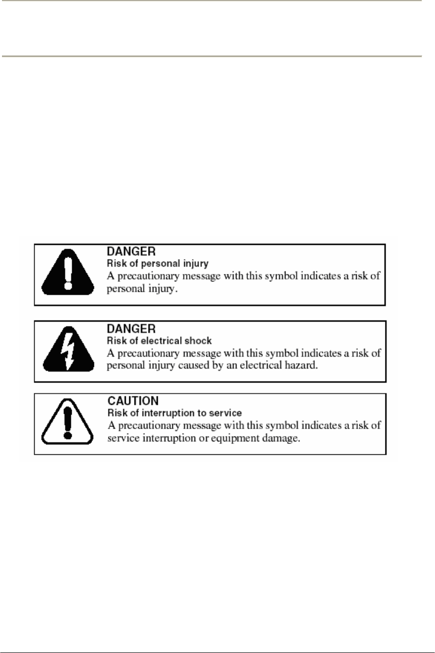
The following precautionary messages appear in APU/CSU 802.11b POE
documentation:
The graphic symbol of an exclamation point within an equilateral triangle warns
the user of the device that it is necessary to refer to the instruction manual and its
warnings for proper operation of the unit.
17
Access Point Unit: 2.4G-B-Radio-POE NTPM99AE 01 Rel 1.0 Issue1 May 2007
Safety Precautions
Refer servicing to a qualified technician who is familiar with NEC
(National Electrical Code) and a related regulation for installation to reduce
the risk of electrical damage when the unit does not appear to operate
normally or exhibits a marked change in performance.
Make sure that the radio unit and antenna should be properly grounded to
protect the equipment and person from ESD and a lighting strike in
accordance with National and Local Electrical Code.
Do not install the equipment and antenna near high voltage power source
and line, keeping them at least 1 m (3ft) away from such a high voltage and
current facility like a power cable.
An appropriate disconnect device shall be provided as part of the
installation in the end system.
It is crucially recommended that a rated surge arrestor is inserted between
antenna connector and antenna cable to prevent the equipment from being
damaged by lightening strike from thunderstorm.
Be sure all exposed connectors are sealed with an appropriate shrinkable
tube and tape for waterproof. Alternatively, you can overlap and seal the
waterproofing material with a silicon and plastic tape to protect it from UV
radiation and other harmful environment.
Warning
MTI co. ltd is not liable for any kinds of damage or violation of law or regulation that
is caused by incautiousness or failing to comply with the guideline and instruction of
this user manual.

18
Access Point Unit: 2.4G-B-Radio-POE NTPM99AE 01 Rel 1.0 Issue1 May 2007
Radio Regulation Conformance
This equipment has been tested and found to comply with the limits for a Class B digital device,
pursuant to Part 15 of the FCC Rules. These limits are designed to provide reasonable protection
against harmful interference in a residential installation. This equipment generates, uses and can
radiate radio frequency energy and, if not installed and used in accordance with instructions,
may cause harmful and, if not installed and used in accordance with instructions, may cause
harmful interference to radio communications. However, there is no guarantee that the
interference will not occur in a particular installation.
FCC RF Radiation Exposure Statement
This device complies with Part 15 of the FCC rules. Operation is subject to the following two
conditions: (1) this device may not cause harmful interference. And (2) this device must accept
any interference received, including interference that may cause understand operation.
The antenna(s) used for this transmitter must be installed to provide a
separation distance of at least 20 cm from all persons and must not be co-
located or operating in conjunction with any other antenna or transmitter.
For point to multi-point application, the transmitted power of the APU and
CSU does not exceed 36 dBm (4W).
The antenna having higher gain than the max antenna per type certified by
FCC is prohibited for use with this system in accordance with FCC rules.
The maximum allowed antenna gain varies according to the antenna types
specified in the Appendix of this manual.
The max gain of antennas allowed at 2.4GHz(ISM) for APU is as below:
14dBi(Directional), 9dBi(Bi-directional), 7dBi(Omni-directional)
The applicable antenna at 5.8GHz (U-NII/Upper) is 22dBi (Directional) for
APU and 12dBi (Directional) for CSU.
Make sure that the installation of antenna and equipment comply with radio
regulation and a instruction described in this user manual(Such as antenna
and cable as well as a surge arrestor)
Warning
MTI co. ltd is not liable for any kinds of damage or violation of law or regulation that is caused by
incautiousness or failing to comply with the guideline and instruction of this user manual

19
Access Point Unit: 2.4G-B-Radio-POE NTPM99AE 01 Rel 1.0 Issue1 May 2007
Overview
Introduction
This document describes the system features used in the APU/CSU 802.11b POE Release
1.0 Product.
The APU/CSU 802.11b POE is an outdoor hardened, strand-mountable access point solution
designed to extend the reach of the cable operators’ hybrid fiber coax network utilizing wireless
technologies from existing rights of ways. This solution from MTI provides corporate network
administrator a fast, low-cost alternative for delivering service to new customers by eliminating
the time, permits, and construction costs associated with extending aerial or buried drops.
The APU/CSU 802.11b POE solution provides:
Flexible service platform
The WLAN Cable Access Point 6220 is a flexible service platform giving cable operators the
ability to offer many different wireless services such as Public Hot Spots and Commercial High
Speed Data services.
Standard Compliance and Interoperability
The APU/CSU 802.11b POE utilizes standard-compliant Ethernet interface, thus ensuring
interoperability with the existing corporate or ISP access network. Wireless access is
accomplished using industry-standard IEEE 802.11 radios approved by government regulatory
agencies for use in “unlicensed” ISM and U-NII band frequencies.
Security
Security is of the highest importance when delivering wireless services. The APU/CSU 802.11b
POE adheres to industry standards for 802.11 devices and augments those standards with
additional security features designed to provide both the cable operator and the end-user
maximum protection.
Performance optimization via multiple antenna options
MTI provides antenna options specifically engineered to enable the APU/CSU 802.11b POE to
achieve peak link performance in Line of Sight (LOS) and Near LOS applications.
Ease of installation
Designed for simple, fast installation by professional technicians, the APU/CSU 802.11b POE is
installed in a simple three-step procedure: lock down strand clamps, connect power via coax
drop, and attach and align antenna for service optimization
20
Access Point Unit: 2.4G-B-Radio-POE NTPM99AE 01 Rel 1.0 Issue1 May 2007
Figure 1-1 APU/CSU 802.11b POE Service Concept Diagram
21
Access Point Unit: 2.4G-B-Radio-POE NTPM99AE 01 Rel 1.0 Issue1 May 2007
Product Description
APU (Access Point Unit)
The following is APU/CSU 802.11abg POE features:
xThe enclosure has three sorts of connectors which support the connection to existing
Ethernet based network, Antenna and Monitoring Equipment.
xOperating Power and Data Traffic are mixed at POE Injector ahead of a transmission
equipments and be carried over CAT5 cable line toward the POE port on the APU.
xBasically, two kinds of mounting types are available for the APU, such as a steel wire
strand mounting and wall mounting as well. But, for the wall mounting, another optional
bracket kit will be required for installation.
xThere are the three available antennas as ‘Directional Type’, ’Bi-directional Type’ and
‘Omni-directional Type’, which can be mounted on the front or rear cover of the APU
with a Universal Bracket. But, the directional antenna having a high gain (22dBi) is
applicable for 802.11a (5.8GHz) in the present.
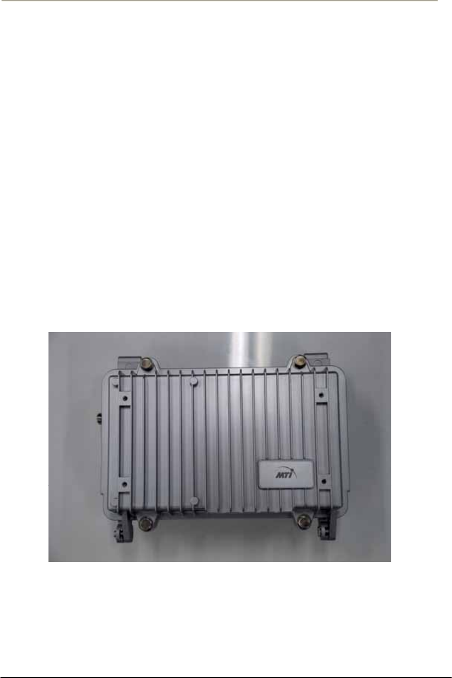
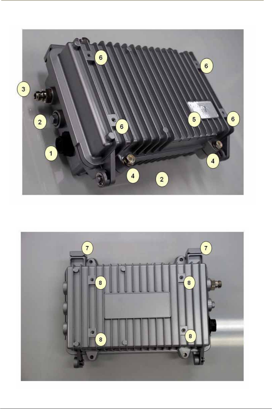
Figure 1-2 APU 802.11abg POE
22
Access Point Unit: 2.4G-B-Radio-POE NTPM99AE 01 Rel 1.0 Issue1 May 2007
Figure 1-3 APU (Top head)
Figure 1-4 APU (Bottom)
23
Access Point Unit: 2.4G-B-Radio-POE NTPM99AE 01 Rel 1.0 Issue1 May 2007
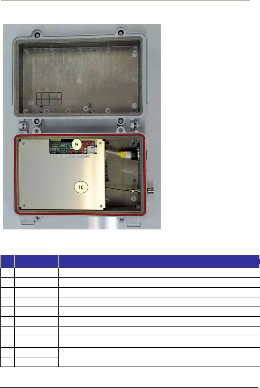
Figure 1-5 APU (Inner panel)
Table 1-1 Modules and Connectors (APU)
Item Label Description & Function
1 POE Port Port for network and power connection from POE Injector
2 Reserved Port Reserved Location for a future upgrade and revision
3 Antenna Port Port for antenna connection
4 Lid Bolt Lid Bolt for closing a case of APU enclosure
5 Logo Panel Location for Vendor Logo
6 Antenna Mount Hole Screw Holes for mounting a APU antenna with a universal bracket
7 Clamp Module Provide strand mounting function to APU, Strand Clamp and Mount Bosses
8Mount Hole
Grounding Hole
Screw Holes for mounting a APU body with a universal bracket and grounding the APU
enclosure
9 System board Mini-PCI type III Radio Card, System Board(Wi-Fi & Secure Data Mode TM) with POE Splitter
10 Inner Panel Protects the main system boards (WLAN AP, POE PD) by covering over them.
24
Access Point Unit: 2.4G-B-Radio-POE NTPM99AE 01 Rel 1.0 Issue1 May 2007
CSU (Corporate Service Unit)
The following is a list of CSU 802.11b POE features:
xEnclosure has a POE connection interface and a DC Power Adapter Jack at the bottom of
the CSU.
xOperation Power & Data Traffic are mixed at POE Injector and supplied to the Ethernet
Port on the CSU through CAT5 Cable.
xTwo types of mounting alternatives are available, pole mount and wall mount. If wall
mount is used a mounting kit will be required.
xThe antenna is basically a Flat Panel type which is a built-in CSU body protected by a
plastic material RADOME.
xWLAN AP supports the secure mode connection which means that wireless traffic from
APU and CSU is not scanned and detected by a conventional sniffing program like
‘Netstumbler’.
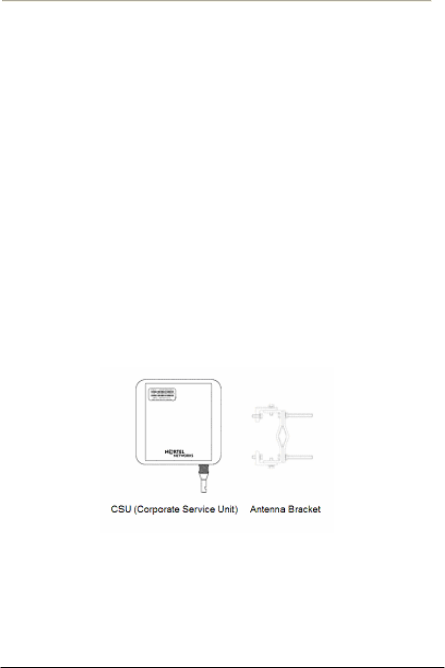
Figure 1-8 CSU 802.11b POE Package Components
25
Access Point Unit: 2.4G-B-Radio-POE NTPM99AE 01 Rel 1.0 Issue1 May 2007
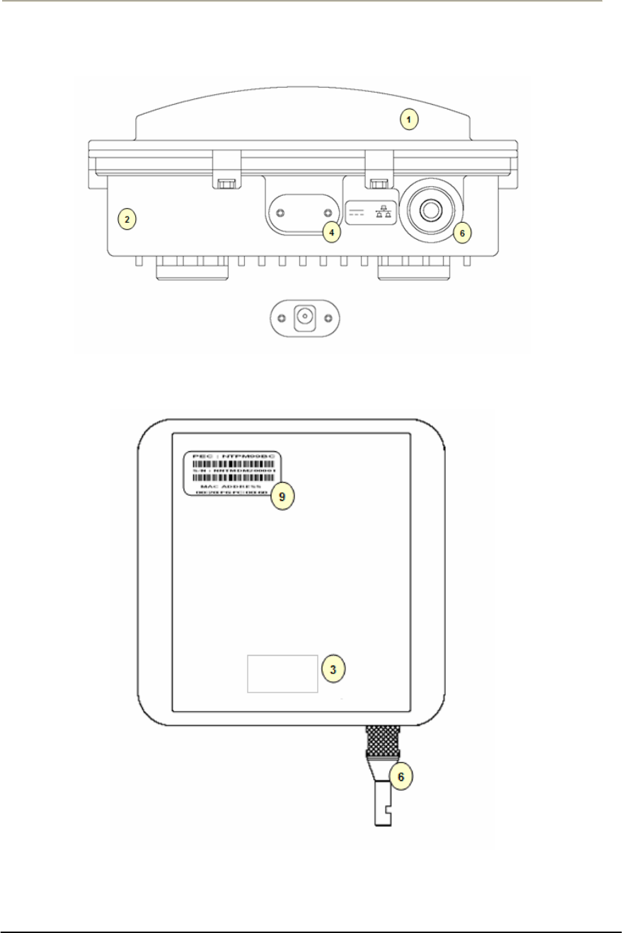
Figure 1-9 CSU 802.11b POE(Bottom)
Figure 1-10 CSU 802.11b POE (Front)
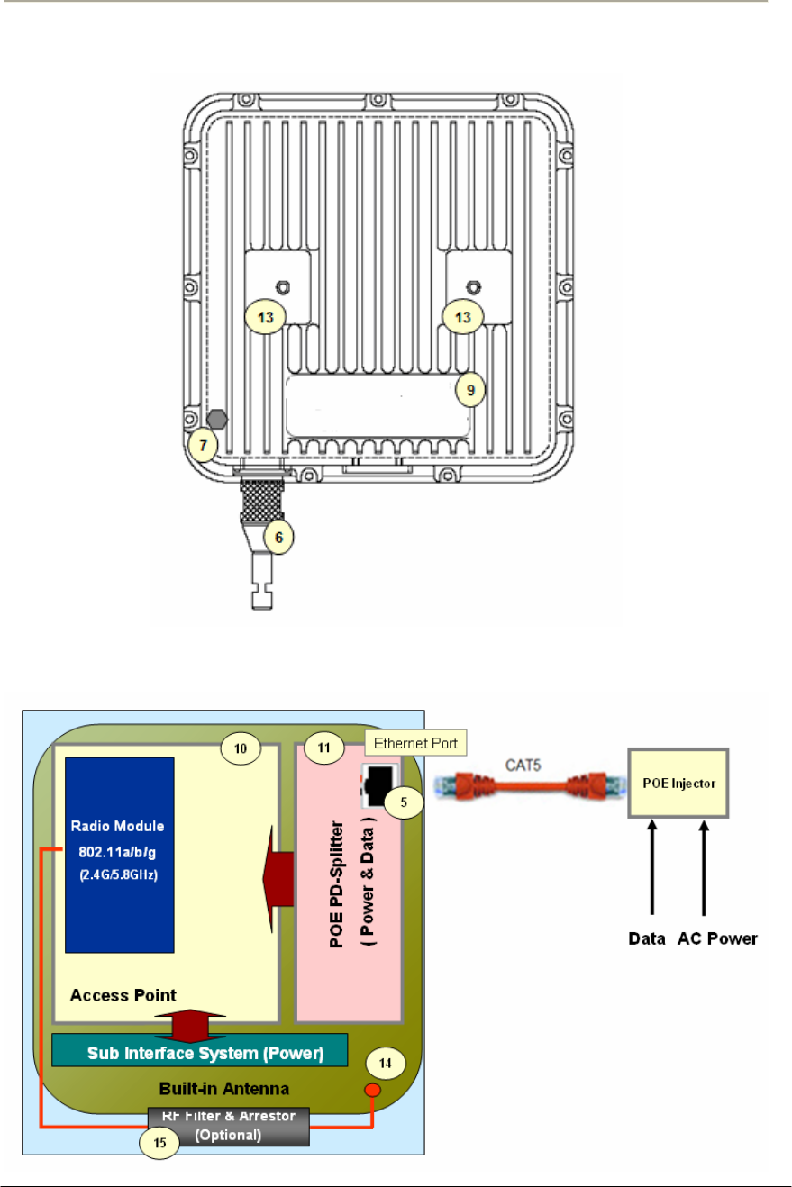
26
Access Point Unit: 2.4G-B-Radio-POE NTPM99AE 01 Rel 1.0 Issue1 May 2007
Figure 1-11 CSU 802.11b POE (Back)
Figure 1-12 CSU 802.11b POE
27
Access Point Unit: 2.4G-B-Radio-POE NTPM99AE 01 Rel 1.0 Issue1 May 2007
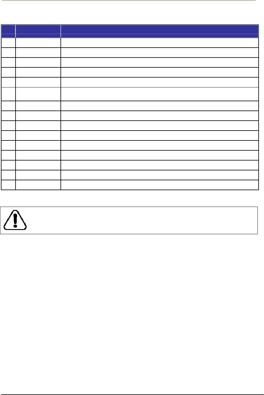
Table 1-2. Modules and Connectors (CSU)
Item Label Description & Function
1 Antenna Cover Protective Cover designed to contain a built-in antenna
2 Enclosure(Body) Housing Integrated with an Antenna Case Assembly
3 Logo Panel Location for Vendor Logo
4 DC Power Socket Provide DC power(12V) from AC-DC Adaptor to CSU
5 Ethernet Port(POE) Provide data connection between CSU and POE Injector or LAN Switch
6 EMI Cap
EMI Cap designed to prevent CSU from interfering to or from other devices
Additionally, provide water proof feature accompanied by sealing tape
7 Ground Point Location for grounding the enclosure to earth for protecting the product from damage
8 Label(Front) Location for attaching a product label which include S/N,PEC,MAC address and so on
9 Label(Back) Location for attaching a product label which include S/N,PEC,MAC address and so on
10 Access Point Mini-PCI type III Radio Card, System Board(Wi-Fi & Secure Mode TM)
11 POE Splitter Power Module to divide Ethernet Signal and DC power combined signal from POE Injector
12 POE Injector Provide 802.3af based signal to CSU through Ethernet Port on CSU
13 Bracket Hole Bolt Hole for assembly of mounting bracket
14 Built-in Antenna 2.4GHz or 5GHz Radio Frequency Antenna (Flat Panel)
15 RF Filter & Arrestor RF module protecting from out-high voltage surge and ESD damage
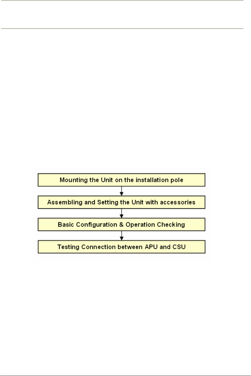
THE 12V POWER CONNECTOR IS NOT INTENDED FOR FIELD USE. THIS
SOCKET IS ONLY APPLICABLE FOR A SPECIAL USE AT FACTORY OR
REPAIR FACILITY.
28
Access Point Unit: 2.4G-B-Radio-POE NTPM99AE 01 Rel 1.0 Issue1 May 2007
Installation
General
This section provides a complete set of procedures for the installation of
APU/CSU 802.11b POE equipment. It includes cable assembling
information as well as required connection information for the WLAN
6220 units, mounting and powering instructions.
It is intended for use by trained installers familiar with Wireless
equipment installations.
For technical assistance, contact your next level of support or MTI
according to the information available in Technical Support and
Information section.
Installation Procedure Summary
Required Tools and Materials
Before you install the APU/CSU 802.11b POE, ensure you have the
following:
APU POE package does not contain an antenna and universal antenna
bracket kit while CSU POE does not require any antenna kit due to built-
in antenna type . For list of antennas and accessories, see the APU/CSU
802.11b POE manual or contact your local MTI representative.

29
Access Point Unit: 2.4G-B-Radio-POE NTPM99AE 01 Rel 1.0 Issue1 May 2007
IEEE 802.3af-2003-compliant Power over Ethernet (POE)
injector
Note: Ensure that the POE Injector is UL/cUL approved,
with LPS (limited power source) output.
Heat gun with propane/ Mapp torch
1 CAT5 Ethernet Extender Coupler
“Document CD” and “Software CD” that contains the APU /
CSU Configurator, online help for the System Configuration, and
various documents.
PC or workstation with a Web browser for configuration

30
Access Point Unit: 2.4G-B-Radio-POE NTPM99AE 01 Rel 1.0 Issue1 May 2007
Pre-Study for
Wireless Network Design and Deployment
Requirement for Site planning
A wireless network requires more additional considerations and factors
for deployment than a wired network in order to achieve the maximum
performance.
Link Budget and Service Coverage
Clearance (FRESNEL Zone, Earth Curvature)
Network Provision(Backhaul, Local Network)
Radio Regulation and Electrical Code(National, Local)
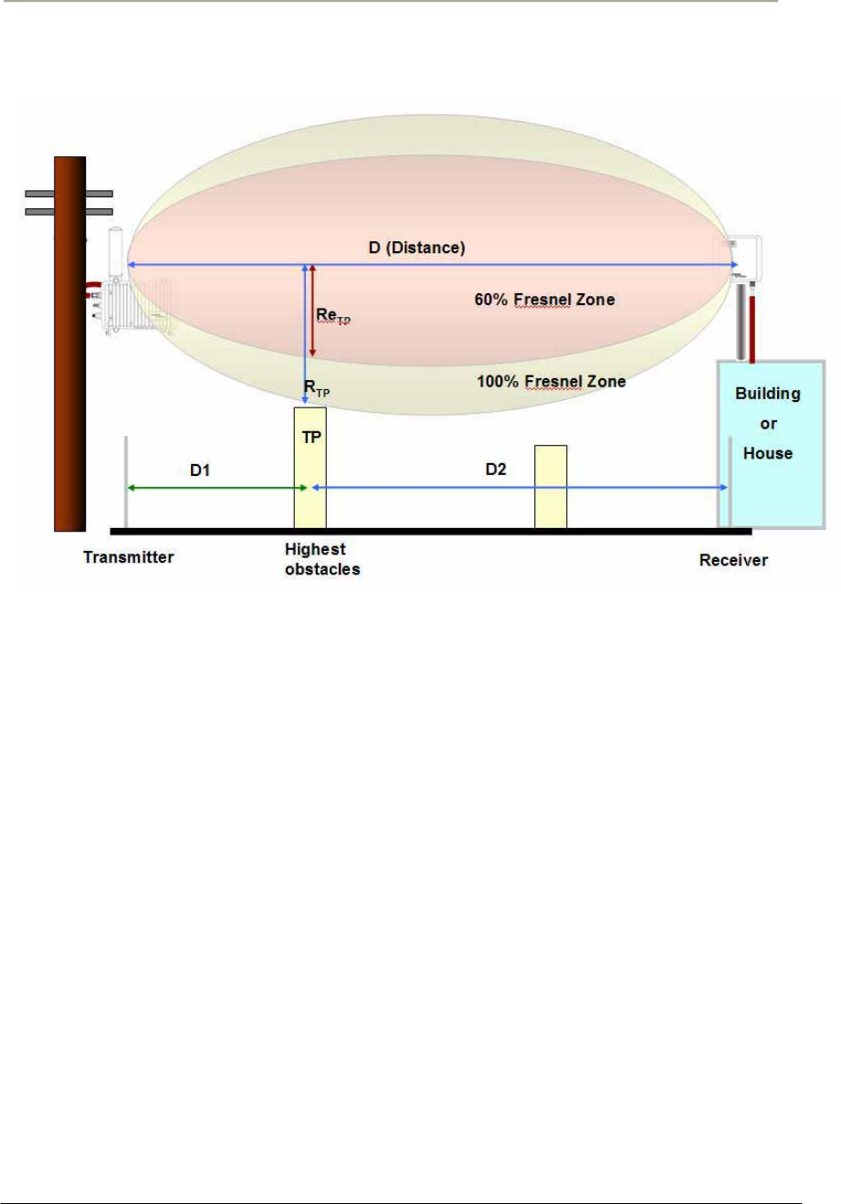
FRESNEL Zone
The radio links between all end sites are specified as three types of
environmental connection as listed below:
LOS (Line Of Sight)
OLOS (Optical LOS)
NLOS (Non LOS)
Although you find a suitable location where it is on a line of sight with
an remote unit, you should be aware of the important concept on
“FRESNEL Zone (pronounced fre-nell)”, a key factor of OLOS(Optical
Line Of Sight) because the antenna beam does not shape a simple
straight and narrow beam even in case of a high directional antenna.
Note: The FRESNEL Zone is a theoretical three-dimensional envelope
around the line of sight of an antenna transmission.
When any objects are obstructed in this zone, it can cause the received
signal strength of the transmitted signal to fade and out-of-phase
reflections and absorption of the signal resulting in signal cancellation.
Following is the typical obstacles you will encounter and must be
avoided to operate effectively:
Buildings
Trees or moisture vegetation
Power and CATV line
Metallic structure like roof or wall
Crowed Parking Lot
Water surface
31
Access Point Unit: 2.4G-B-Radio-POE NTPM99AE 01 Rel 1.0 Issue1 May 2007
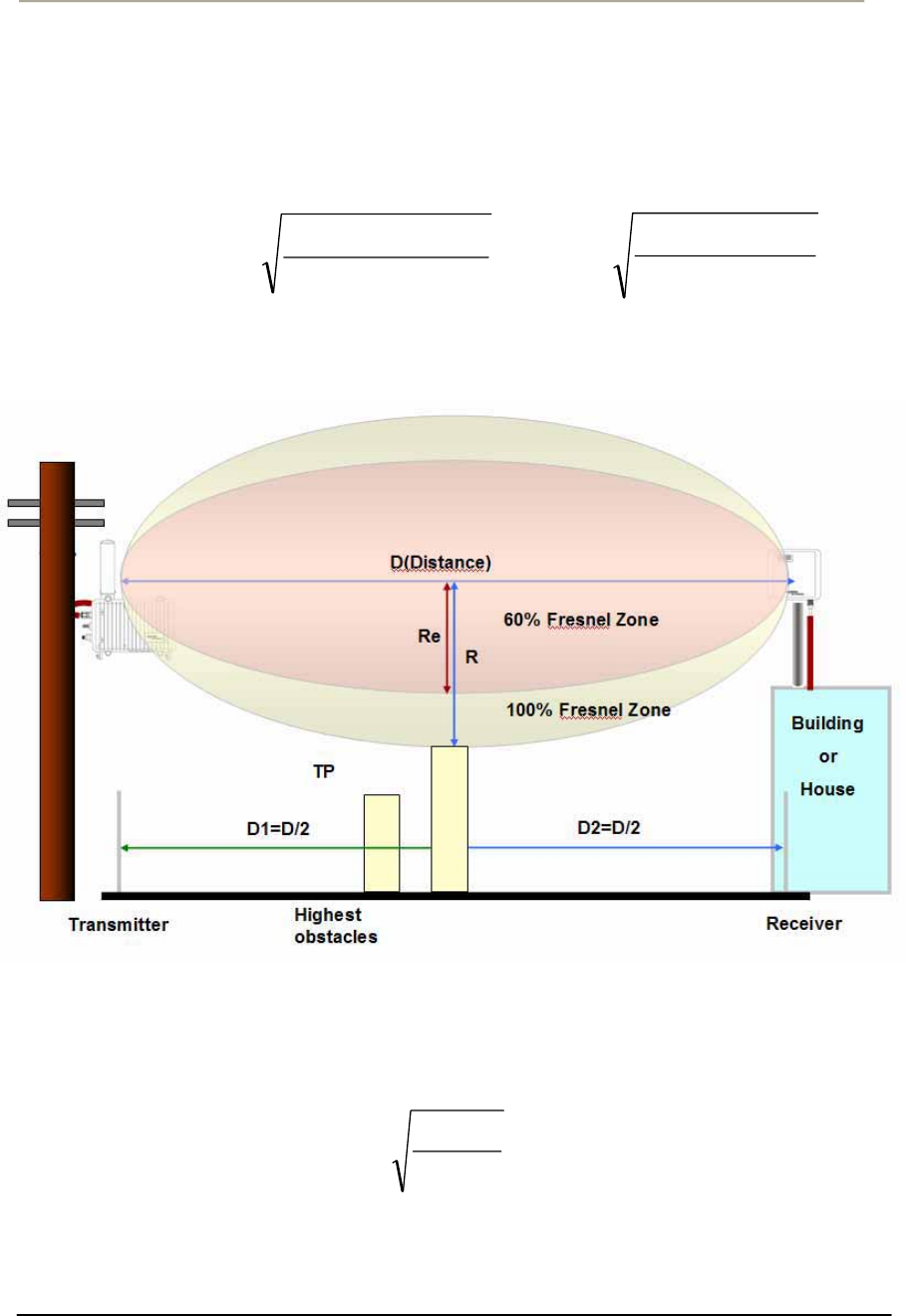
The FRESNEL zone is calculated along the path, usually for the distance
of each of the highest obstacles points, so the FRESNEL zone is plotted
or drawn comparable to the terrain data. The formula of FRESNEL zone
is a function of the wavelength (Ʌ) and the distance along the path from
each endpoint (D1 and D2):
R = 21
21
DD
DDN
uuu
O
=)21(
21
6.72 DDf
DDN
u
uu
u
Figure 2-1 FRESNEL Zone
Typically, the first Fresnel zone (N=1) is used to determine obstruction
loss while the highest obstacles are assumed as located in the center of
wireless path between the endpoints.
R = )4(
6.72 F
D
u
u,where D1=D2=D/2, N=1
D: Distance in miles between antennas
F: Frequency in GHz
32
Access Point Unit: 2.4G-B-Radio-POE NTPM99AE 01 Rel 1.0 Issue1 May 2007
Figure 2-2 Typical FRESNEL Zone
Calculation Example
Case I.
D: 1 [mile] , where D1=D2=D/2=1/2=0.5 mile
F: 2.4 [GHz]
R = 72.6 x sqrt (1/ (4x2.4)) [feet]
= 23.25 feet (7.07 meter)
Re = 73.54 * 0.6 = 13.95 feet (4.242 meter)
Case II.
D: 1 [mile] , where D1=D/4=0.25 mile, D2=3*D/4=0.75 mile
F: 2.4 [GHz]
R = 72.6 x sqrt ((0.25*0.75)/ (4x2.4)) [feet]
= 20 feet (6 meter)
Re = 20 * 0.6 = 12 feet (3.6 meter)
33
Access Point Unit: 2.4G-B-Radio-POE NTPM99AE 01 Rel 1.0 Issue1 May 2007
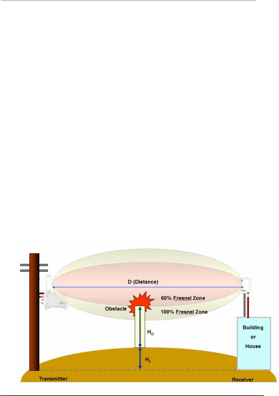
Earth Bulge
For long distance transmission, the curvature of the earth will may block
the line of sight path unless the antennas at both ends of the link are
positioned high enough above the ground.
The formula of earth bulge is simply a function of the distance along the
path from both endpoints as below.
HE = D^2/8
HE = Earth bulge height in feet
D=distance between antennas in miles
This height must be added to that of obstacles so that the earth curvature
effect can be applied to the calculation of the FRESNEL Zone and
determination of antenna height.
On the assumption that the distance between a transmitter and receiver,
you solve this earth bulge effect by raising the mounting height of
antenna so the beam path can be changed and moved to more higher.
In Figure 3-3, you can find that some obstacle resides in 60% FRESNEL
Zone of the beam pattern between both ends, which might be affected by
such an earth bulge effect due to long distance.
Figure 2-3 Earth Bulge effect (Before raising the antenna)
34
Access Point Unit: 2.4G-B-Radio-POE NTPM99AE 01 Rel 1.0 Issue1 May 2007
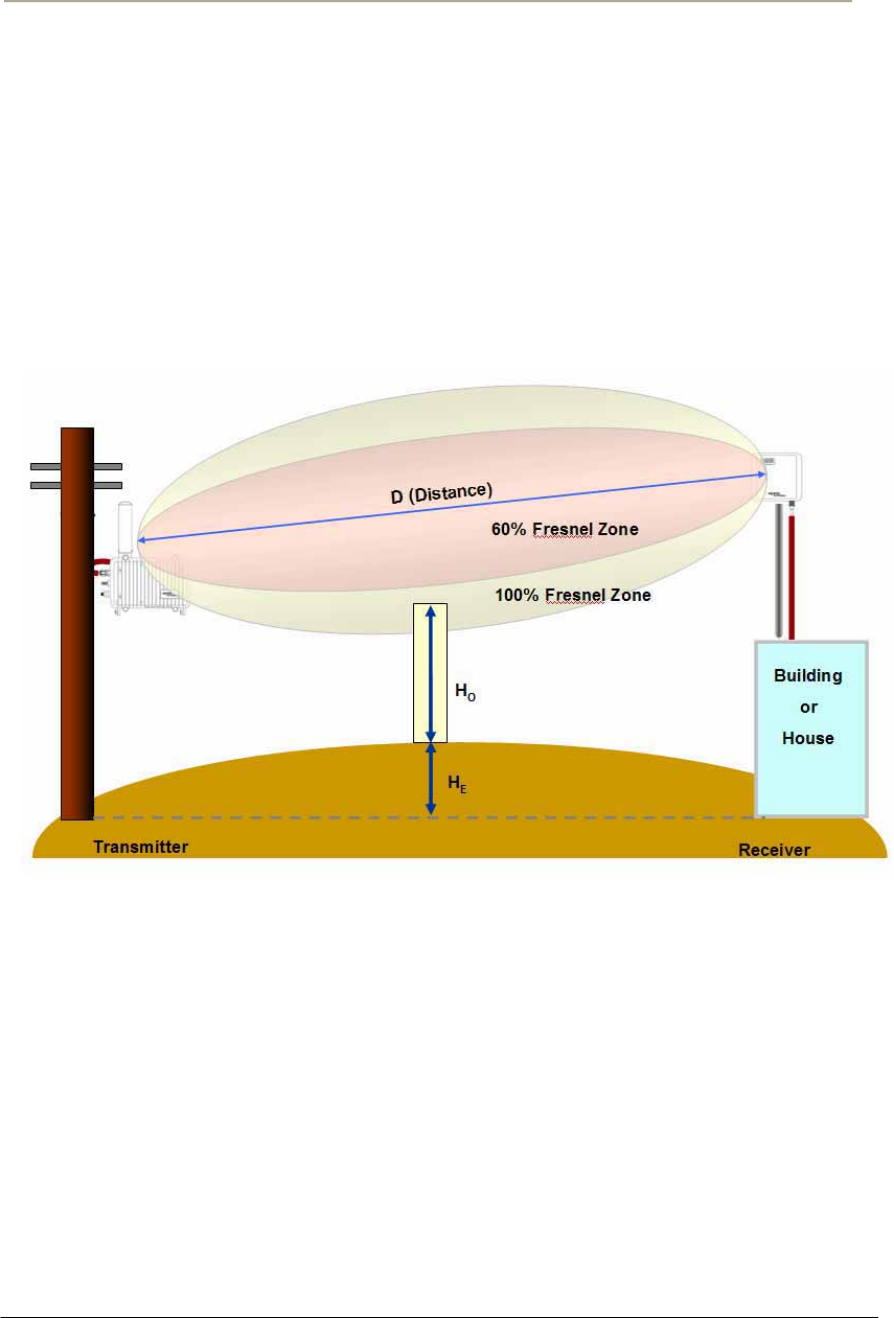
Such a situation can be cleared through the antenna location change,
exactly raise of antenna height, which will be a best solution on the
condition that the installation points are limited due to a field
environment and local regulation.
In Figure 3-4, you can find that the interfering obstacle has been kept
apart from the 60% FRESNEL Zone by raising the antenna height of the
receiver.
Figure 2-4 Earth Bulge effect (After raising the antenna)
Note: Even though the earth bulge effect is one of what you have to
consider at the installation, you may neglect such an effect for a short
path distance for a rural area or residential street area.
For a MSO application with APU and CSU, it is highly effective at
installation to assume that the earth bulge effect can be skipped at the
calculation of clearance.
35
Access Point Unit: 2.4G-B-Radio-POE NTPM99AE 01 Rel 1.0 Issue1 May 2007
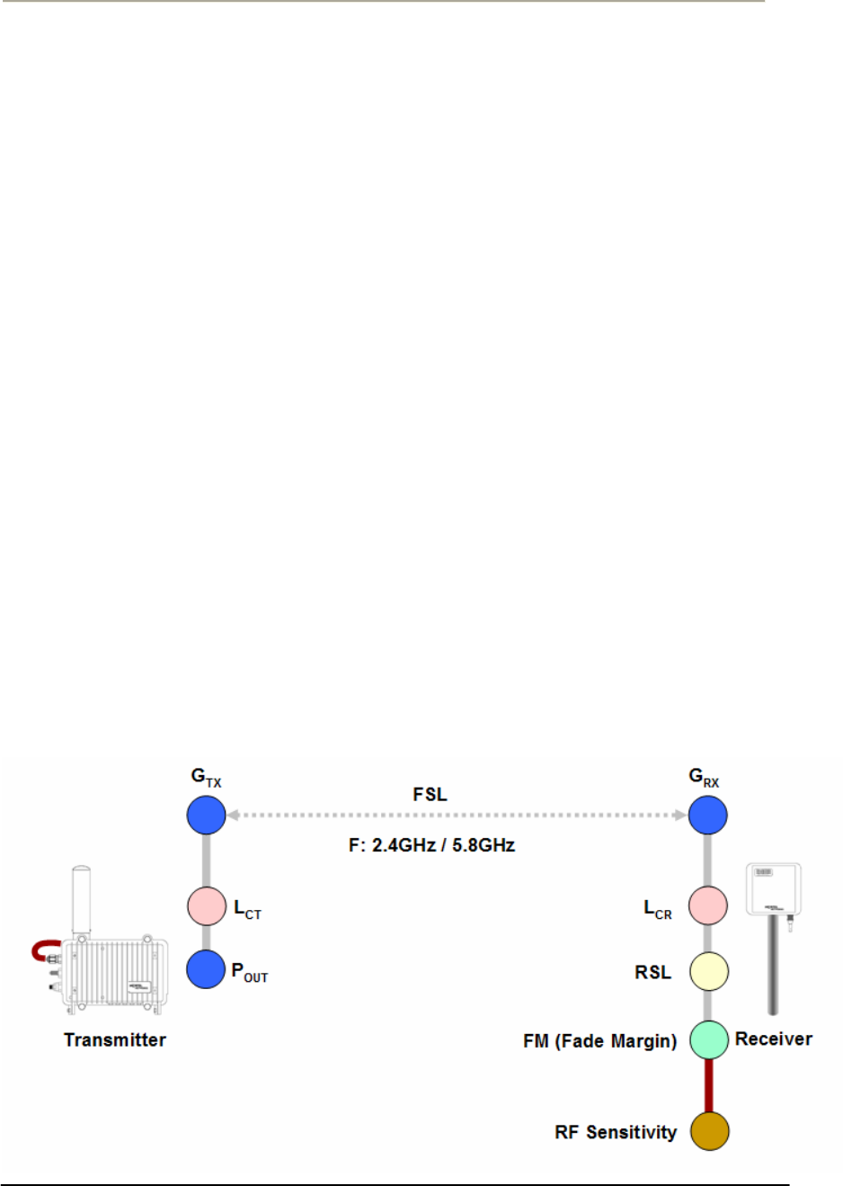
Link budget and Max Distance
Prior to an actual installation, it is prerequisite to predict an arriving
signal level at the receiver and determine the fade margin to achieve a
system redundancy so that the radio system can be designed for a
specific service quality as well as system availability.
The system factors affiliated with link budget can be calculated by the
formula listed below
RSL (Received Signal Level) = Pout + Gtx + Grx – Lct – Lcr - FSL
Pout: Transmitter Output Power(Conducted) in dBm
Gtx: Transmitter antenna gain in dBi
Grx: Receiver antenna gain in dBi
Lct: Transmission loss between antenna and Transmitter module in dB
Lcr: Transmission loss between antenna and Receiver module in dB
FSL: Free space loss attenuation in dB
* FSL = 92.4 + 20Log(F) + 20Log(Rkm) [MKS]
= 36.56 + 20Log(F) + 20Log(Rmile) [Mile]
where, F: Frequency (MHz), R: Range (Km/mile)
FM(Fade Margin) = RSL – (Receiver Sensitivity Level)
Figure 2-5 Link budget and Fade margin

36
Access Point Unit: 2.4G-B-Radio-POE NTPM99AE 01 Rel 1.0 Issue1 May 2007
Frequency Channel Selection
Radio spectrums are consisted of many frequency bands for a particular
application like 802.11 based products and each band contains several
operating channels at which each radio unit communicate with other
units.
Such a spectrum is managed by a number of regulatory organizations.
FCC(Federal Communications Commission) is one of those
organizations who manage a usage of radio spectrum at local and state
area in US and the rules of FCC has been adopted by other countries as
well as North America. EU adopted it’s own regulatory rules and channel
allocation performed by ETSI(European Telecommunication Standards
Institute) and ERO(European Radio-communications Office).
Currently, 802.11b/g is the most popular standard for WLAN system that
in the United States uses one of the occupied channels in ISM
band(Industrial, Scientific and Medical) from 2.400 to 2.483 MHz while
802.11a is a newly emerging standard that use a different band with
802.11b as U-NII band(5.15~5.825GHz) or ISM(5.725~5.850GHz).
The bandwidth of 802.11b channel is 22MHz and the center frequency is
apart from neighbor channels by 5MHz as a summation of total channel
bandwidth is smaller than a allocated band. So, only three channels can
be available in the band without any adjacent channel interference. ie
CH1(2.412GHz), CH6( 2.437GHz), CH11(2.462GHz).
This limitation is caused by the characteristic of 802.11b that permit the
operating channels to be overlapped with each different channel because
the channel bandwidth (22MHz) is larger than the channel step(5MHz).
Whereas, 802.11g uses OFDM (Orthogonal Frequency Division
Multiplexing) at ISM band which is more advantageous and resilient to
multi-path effect and interference.
802.11a uses OFDM modulation method like 802.11g at another
frequency bands named as “U-NII: Unlicensed-National Information
Infrastructure”
,which is consisted of three sub-bands as Low band(5.15~5.25GHz),
Middle band(5.25~5.35GHz), High band(5.725~5.825GHz).
Alike 802.11b/g, 802.11a standard does not allow such an overlapped
channels so that a installer don’t have to consider any overlapping
channels but adjacent channels. This change made the number of
channels for 802.11a to have less channels than 802.11b/g mode.

37
Access Point Unit: 2.4G-B-Radio-POE NTPM99AE 01 Rel 1.0 Issue1 May 2007
Table 2-1 Radio channel usage in different countries (802.11b/g)
CH Center frequency (GHz) US/Canada ETSIbFrance
1 2.412 • •
2 2.417 • •
3 2.422 • •
4 4.427 • •
5 2.432 • •
6 2.437 • •
7 2.442 • •
8 2.447 • •
9 2.452 • •
10 c 2.457 • • •
11 2.462 • • •
12 2.467 • •
13 2.472 • •
Table 2-2 Radio channel usage in United States and EU (802.11a)
CH Center frequency
(GHz) US/Canada ETSIbRemark
36 5.180 • •
40 5.200 • •
44 5.220 • •
U-NII
Lower
Band 48 5.240 • •
Indoor
Use Only
52 5.260 • •
56 5.280 • •
60 5.300 • •
U-NII
Middle
Band 64 5.320 • •
100 5.500 • •
104 5.520 • •
108 5.540 • •
112 5.560 • •
116 5.580 • •
120 5.600 • •
124 5.620 • •
128 5.640 • •
132 5.660 • •
136 5.680 • •
U-NII
Middle
Band
-2nd
140 5.700 • •
149 5.745 •
153 5.765 •
157 5.785 •
U-NII
Upper
Band 161 5.805 •
38
Access Point Unit: 2.4G-B-Radio-POE NTPM99AE 01 Rel 1.0 Issue1 May 2007
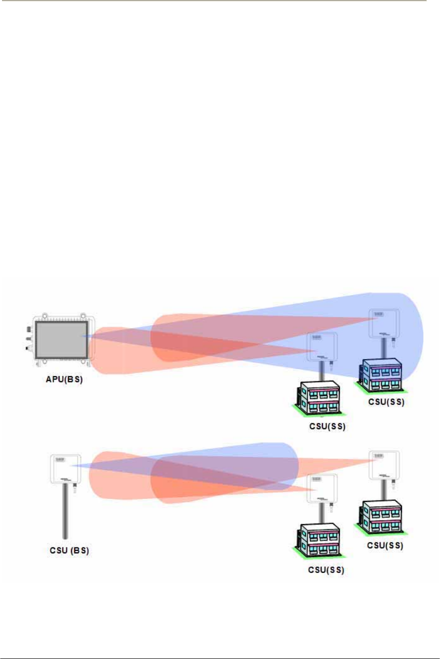
Network Topology and Antenna Selection
This section provides a general concept and designing tips about typical
Point to Multi-Point (PMP) and Point to Point (PTP) network
configuration.
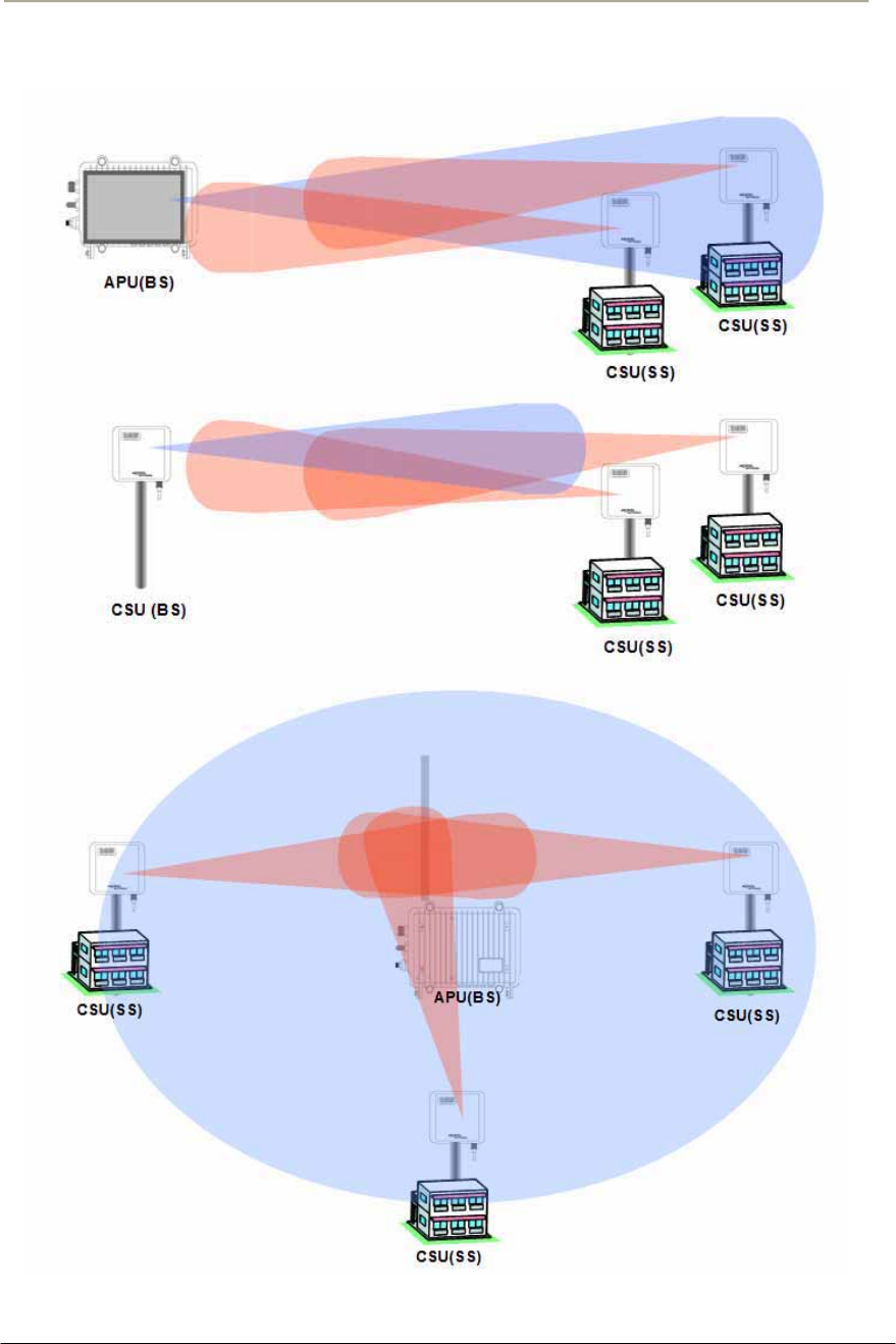
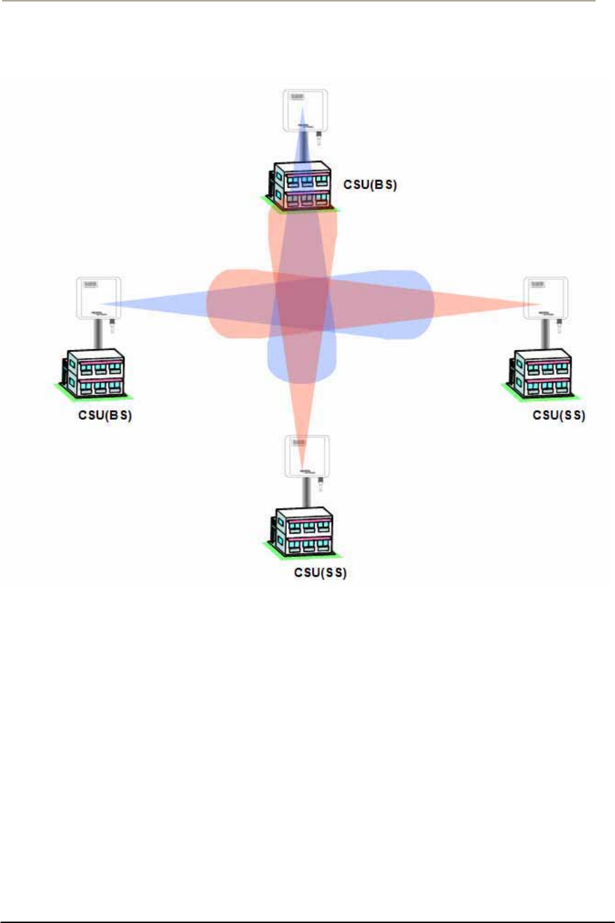
Directional Antenna (Sector)
Flat panel antennas have a directional gain and are ideally suited for
short and medium range bridging. For example, two office buildings that
are across the street from one another and need to share a network
connection would be a good scenario to use flat panel (directional)
antennas.
Figure 2-6 Directional Antenna concept (Flat Panel Antenna): CASE I (Parallel Type)
39
Access Point Unit: 2.4G-B-Radio-POE NTPM99AE 01 Rel 1.0 Issue1 May 2007
Figure 2-7 Directional Antenna concept (Flat Panel Antenna): CASE II (Cross Type)
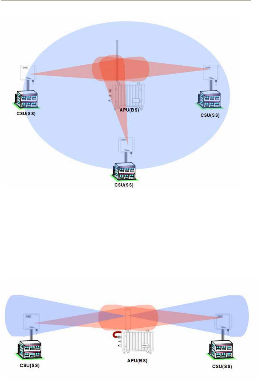
Omni-Directional Antenna
Omni-directional antennas are used when coverage in all directions
around the horizontal axis of the antenna is required. Omni-directional
antennas are most effective where large coverage areas are needed
around a central point, they commonly used for point-to-multipoint
designs with a star topology.
The antenna should be placed on top of a structure (such as a building) in
the middle of the coverage area. For example, in a college campus the
antenna might be placed in the centre of the campus for the greatest
coverage area.
40
Access Point Unit: 2.4G-B-Radio-POE NTPM99AE 01 Rel 1.0 Issue1 May 2007
Figure 2-8 Omni-directional Antenna concept
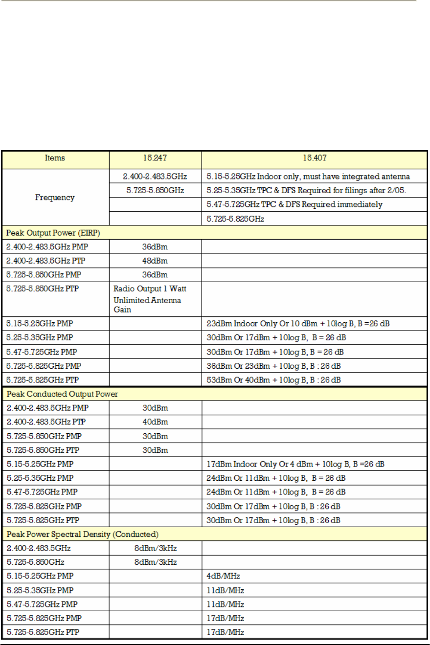
Bi-directional Antenna
Bi-directional antennas are used when coverage is required in a selected
horizontal axis of the antenna is required. Bi-directional antennas are
most effective where a particular coverage area is needed around a
central point. For example, placing a bi-directional antenna along a street
would provide coverage on each side of the street.
Figure 2-9 Bi-directional Antenna concept
41
Access Point Unit: 2.4G-B-Radio-POE NTPM99AE 01 Rel 1.0 Issue1 May 2007
Radio regulation (FCC)
The FCC consists of many rules and regulation to define the spectrum
use and restriction as well as policies.
Basically, 802.11b is subject to FCC rule part 15.247 while 802.11a
should conform to Part 15.407 rule. An Installer should be fully aware of
all FCC rule relevant to 802.11 units referring to the following
summarized table.
Table 2-3 FCC Rules pertaining to WLAN
42
Access Point Unit: 2.4G-B-Radio-POE NTPM99AE 01 Rel 1.0 Issue1 May 2007
APU Installation & Configuration
Mounting and Installation Concept
Figure 2-10 APU Installation Concept
By default, APU is Strand or Pole mountable. Each unit is shipped with a
strand clamp module for default.
The outdoor type Ethernet cable(CAT5/SFTP-STP) is applicable to the
APU for EMI effect to or from other radio equipment.
The APU supports a variety of antenna types: omni-directional, flat panel
and bi-directional. The antenna type should be selected according to the
coverage needed and type of application - please refer to Appendix H for
more detailed information.

43
Access Point Unit: 2.4G-B-Radio-POE NTPM99AE 01 Rel 1.0 Issue1 May 2007
Procedure 1-1
Site survey and Planning
Action
Step Action
1. List up a list of the parameters as below which are required to
calculate a radio link budget and RSL (Received Signal Level) as
well as the receiver sensitivity.
Pout: Transmitter Output Power of Radio card
Gtx: Transmitter antenna gain
Grx: Receiver antenna gain
Lct: Transmission loss between antenna and Transmitter module
Lcr: Transmission loss between antenna and Receiver module
FSL: Free space loss attenuation
2. Find the actual transmitter power associated with data rate and
channel number according to the Output Power tables in the
appendix A.
3. Calculate and determine the proper output power considering the
allowed Max EIRP (Effective Isotropic Radiated Power) in the
appendix A to comply with a regional radio regulatory rule.
Note: APU and CSU are certified as PMP system with the listed
antenna in the Appendix x. Therefore, to avoid any violation of radio
regulation and rules it is recommended to use the certified antennas in
Appendix. B.
4. Find a FSL value from the table according to a distance range(R)
between a transmitter and receiver and center frequency (F).
5. Calculate a RSL (Received Signal Level) with a formula and the
parameters using the formula (1) associated with this.
6. Find the receiver sensitivity for the data rate and transmit mode
from the Receiver Sensitivity in the appendix A.
7. Obtain a Fade margin (FM) by subtracting the receiver sensitivity
from the RSL (Received Signal Level).
Note: The large amount of FM(Fade Margin) indicates the high
reliability of radio system. Therefore, before he moves to the field
site, a system installer should keep in mind that a reliability of a radio
system depends on how much a fade margin is guaranteed.

44
Access Point Unit: 2.4G-B-Radio-POE NTPM99AE 01 Rel 1.0 Issue1 May 2007
8. If the FM result is very small or minus value, you need to enhance
the value by adjusting all parameters of radio unit or reducing the
distance value. But, the EIRP updated by adjusted parameters shall
be compliant to a radio regulatory rule.
Note: 10~15dB is recommended as a desirable FM value for APU
and CSU in a consideration of a various external condition like a
weather or at the installation.
Note: Please use the dedicated program, so called “Link budget
calculator” which provides a system installer with a convenient
solution for calculating a link budget and all system parameters.
9. For quick determination, you can refer to the pre-calculated
parameter table in Appendix C and D.
10. Referring to the assured link parameter and system performance,
move to the site for installation and perform a site survey for the
service area.
11. Check if all pre-selected points are within the maximum coverage
in consideration of antenna type and data rate for a subscriber as
well as enough fade margin (over 10dB).
12. Although you fixed all system design parameters in an imaginary
calculation, actual performance will be different with the expected
one, depending on the interference factors related to “FRESONEL
Zone”.
13. For best performance, APU and CSU must be installed at the
location where it can achieve LOS (Line Of Sight) environment so
that there is no obstacles like tree and bulges in the direct path
between them.
14. Make sure that the link path between two units meet the clearance
condition as follows:
Cond.1: LOS (Line of Sight)
No obstacles in the direct path of antenna between APU and CSU.
Cond.2: OLOS (Optical Line of Sight)
No obstacles within the defined zone around the radio beam pattern,
so called “Fresnel Zone”
Note: The best means of achieving FRESNEL ZONE clearance is
raising the height of APU or CSU mounting point as high as possible.

45
Access Point Unit: 2.4G-B-Radio-POE NTPM99AE 01 Rel 1.0 Issue1 May 2007
15. Collect all information about RF signal quality and used channels
as well as interference at an install location by measuring a
portable spectrum analyzer or other signal measurement equipment.
16. Select an available channel for the unit considering antenna
coverage to avoid an interference with other radio systems.
17. Summarize the final setup parameter for the unit to install and
apply them to the configuration procedure described in the
following sections.

46
Access Point Unit: 2.4G-B-Radio-POE NTPM99AE 01 Rel 1.0 Issue1 May 2007
Procedure 1-2
Assembling the antenna
Common Procedure
1. Unpack the antenna box and check the contents listed in the
manual in the box.
2. Prepare the recommended tools for assembly and installation of
the antenna.
3. Assemble the antenna and bracket kit following the assembly
procedure for the selected antenna type.
4. Perform assembly of antenna and bracket as below.
Action
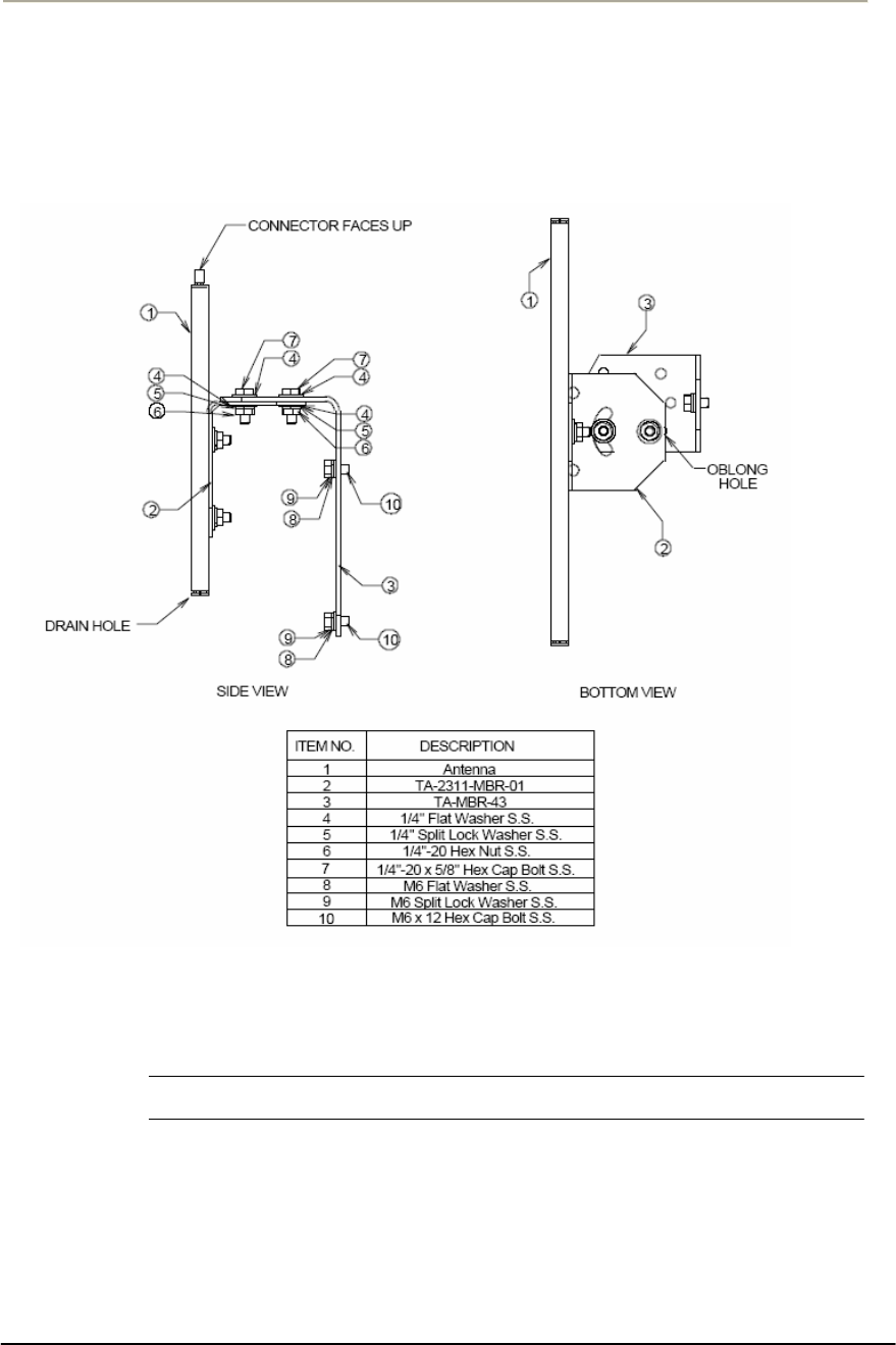
NTA 2407 (Flat Panel Antenna)
Step Action
1. Ensure that each part number is the same as the actual part in the
box and the auxiliary mounting bracket (#2311) is securely
mounted on the antenna body.
2. Attach the universal mounting bracket (#43) to the auxiliary
mounting bracket using the 1/4" flat washers, lock washers, hex
nuts, and hex bolts as shown in the diagram. Ensure that the
brackets are attached through the oblong hole in mounting bracket.
3. With the antenna connector oriented upward, fasten mounting
bracket #43 to the radio using the M6 flat washers, lock washers,
and hex bolts as shown in the mounting diagram.
4. To adjust the pan of the antenna, loosen the 1/4" hex bolts that
attach the auxiliary mounting bracket with universal mounting
bracket, adjust the pan, and re-tighten the bolts.
Lightning Protection
The antenna is at DC ground for lightning protection. If the antenna is
mounted to a non-conductive structure it should in turn be grounded
using practices supplied/approved by the customer.
Weatherproofing
All connections between the antenna connector and the transmission line
must be weatherproofed according to standard industry practices.
Drainage
Since the RADOME is not pressurized, there is a drain hole in the
connector base plate. The antenna must be installed so that the drain hole
remains on the bottom. This drain hole must be kept open so that any
47
Access Point Unit: 2.4G-B-Radio-POE NTPM99AE 01 Rel 1.0 Issue1 May 2007
moisture accumulating inside the RADOME will be able to drain
properly.
Figure 2-11 NTA-2407 Antenna Assembly
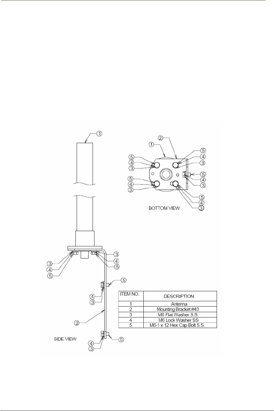
NTA 2400 (Omni directional Antenna)
Step Action
5. Ensure that each part number matches the actual part in the box.
6. Attach the mounting bracket to the antenna using the M6 flat
washers, lock washers and hex cap bolts as shown in the mounting
drawing.
7. With the antenna oriented upward, fasten the mounting bracket to
the radio using the M6 flat washers, lock washers, and hex cap
bolts as shown in the mounting diagram.
48
Access Point Unit: 2.4G-B-Radio-POE NTPM99AE 01 Rel 1.0 Issue1 May 2007
Lightning Protection
The antenna is at DC ground for lightning protection. If the antenna is
mounted to a non-conductive structure (e.g. building wall, wooden pole
etc.) it should in turn be grounded using practices supplied/approved by
the customer.
Weatherproofing
All connections between the antenna connector and the transmission line
must be weatherproofed according to standard industry practices.
Figure 2-12 NTA-2400 Antenna Assembly

49
Access Point Unit: 2.4G-B-Radio-POE NTPM99AE 01 Rel 1.0 Issue1 May 2007
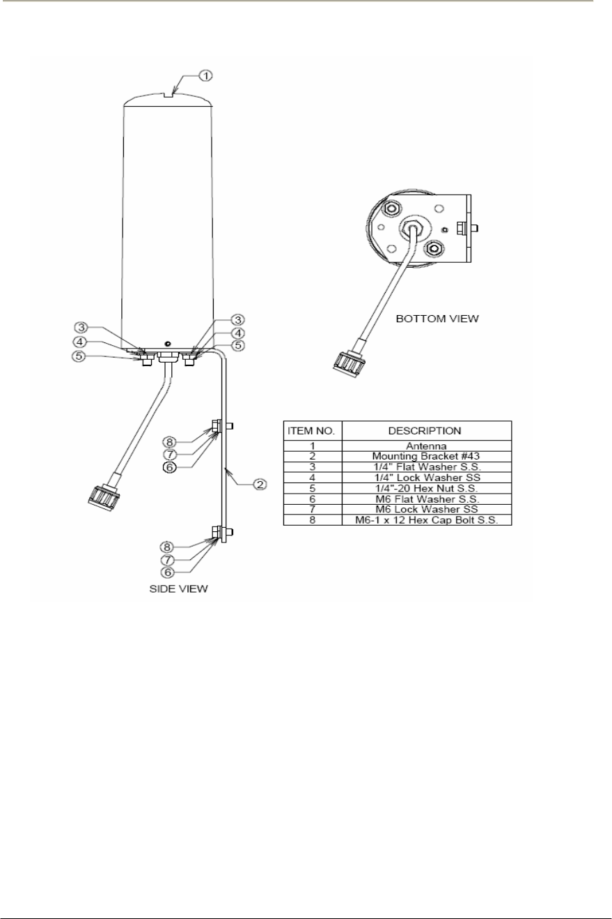
NTA 2412 (Bi-directional Antenna)
Step Action
1. Ensure that each part number matches the actual part in the box.
2. Attach the mounting bracket to the antenna using the 1/4" flat
washers, lock washers and hex nuts as shown in the mounting
drawing.
3. With the antenna oriented upward, fasten the mounting bracket to
the radio using the M6 flat washers, lock washers, and hex bolts as
shown in the mounting diagram.
Lightning Protection
The antenna is at DC ground for lightning protection. If the antenna is
mounted to a non-conductive structure (e.g. building wall, wooden pole
etc.) it should in turn be grounded using practices supplied/approved by
the customer.
Weatherproofing
All connections between the antenna connector and the transmission line
must be weatherproofed according to standard industry practices.
Drainage
Since the RADOME is not pressurized, there is a drain hole in the
connector base plate. The antenna must be installed so that the drain hole
remains on the bottom. This drain hole must be kept open so that any
moisture accumulating inside the RADOME will be able to drain
properly.
50
Access Point Unit: 2.4G-B-Radio-POE NTPM99AE 01 Rel 1.0 Issue1 May 2007
Figure 2-13 NTA-2412 Antenna Assembly
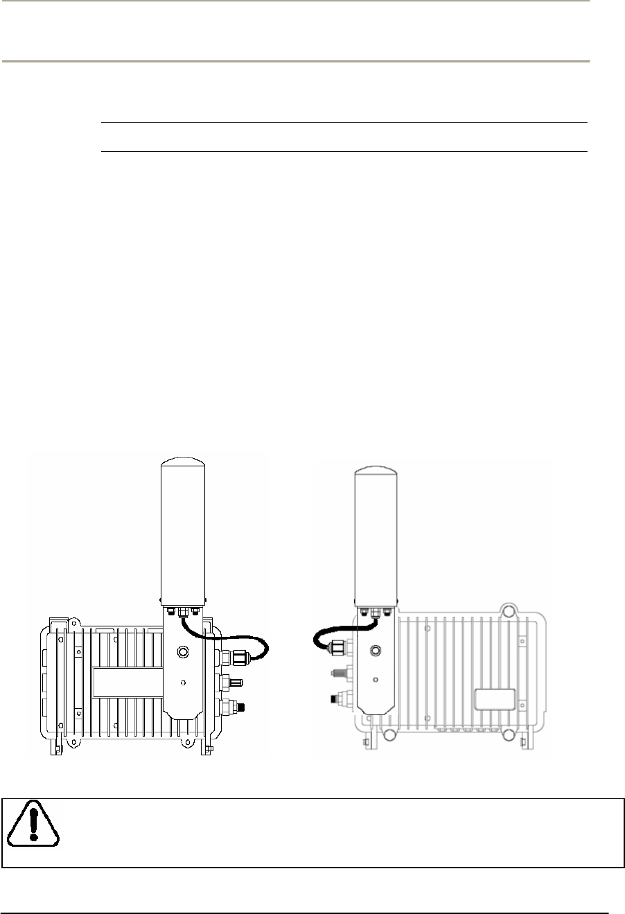
51
Access Point Unit: 2.4G-B-Radio-POE NTPM99AE 01 Rel 1.0 Issue1 May 2007
Procedure 1-3
Antenna Mounting and Cable Connection
Action
Step Action
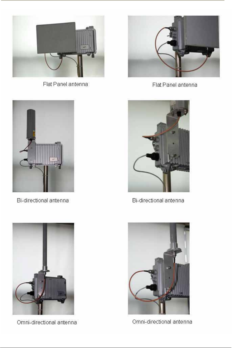
1. Attach the bracket on the back surface of the APU and thread one
flat washer onto each hex bolt. Screw each bolt with the washer
into the two mounting holes.
Note: Even if the APU enclosure has universal mounting holes on the
front and rear cover, we recommend that you do not mount two kinds of
antenna such as omni-directional and bi-directional type on the front
cover. If inevitable, the left side of the front cover is the preferred
location in consideration of antenna cable length.
2. Tighten each bolt until the washer is pressed firmly into the APU
Enclosure.
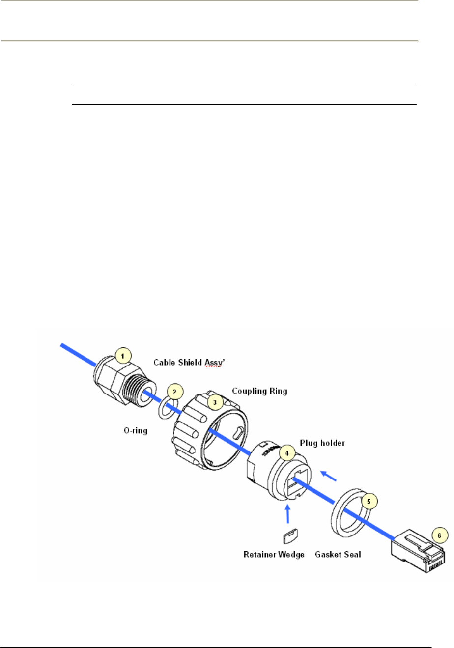
Figure 2-14 Antenna mounting with a bracket
TYPE I TYPE II
Do not install the equipment and antenna near high voltage power source and
line, keeping them at least 1 m (3ft) away from such a high voltage and current
facility like a power cable.
52
Access Point Unit: 2.4G-B-Radio-POE NTPM99AE 01 Rel 1.0 Issue1 May 2007
53
Access Point Unit: 2.4G-B-Radio-POE NTPM99AE 01 Rel 1.0 Issue1 May 2007
Procedure 1-4
Connecting to the APU
Action
Step Action
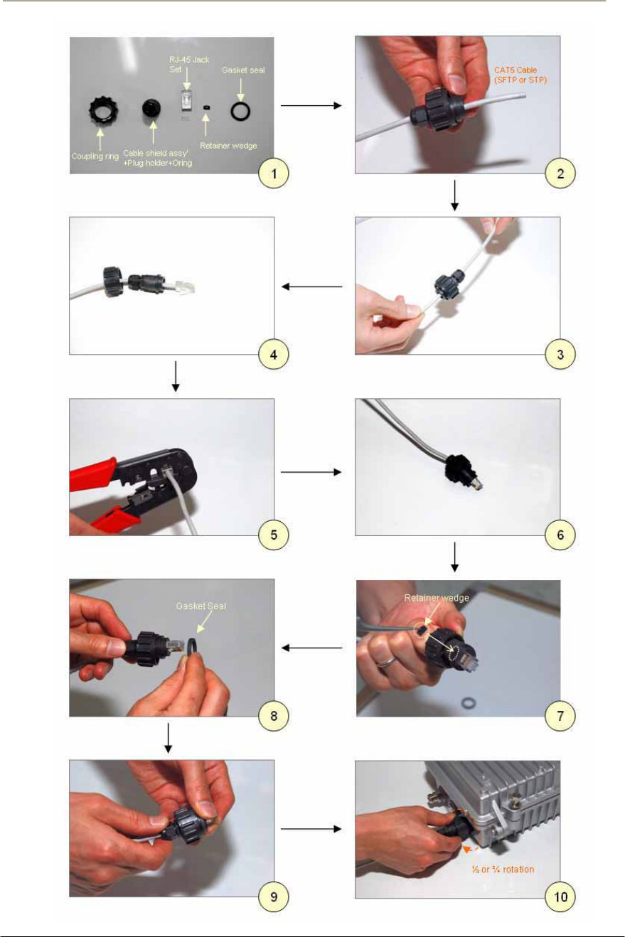
1. Constructing the CAT5 cable connection with the outdoor type RJ-
45 connector packaged in the box following the instruction [Step 1
~ Step 9] illustrated in Figure 2-40.
Note: It is recommended to use a shielded cable like S-FTP(Foiled
Twisted Pair) or STP (Shielded Twisted Pair) in which wire pairs are
covered with overall shield material to prevent EMI effects to or from the
near electronic devices or facilities.
Note: The cable from APU to POE Injector and from POE Injector to
CPE (PC) should be a straight-through cable.
Figure 2-15 Constructing the outdoor POE input jack to APU
54
Access Point Unit: 2.4G-B-Radio-POE NTPM99AE 01 Rel 1.0 Issue1 May 2007

55
Access Point Unit: 2.4G-B-Radio-POE NTPM99AE 01 Rel 1.0 Issue1 May 2007
2. Plug the outdoor RJ-45 Jack to the POE connector on APU
enclosure and then secure the coupling ring by rotating it as a
clock-wise direction. [Step 10]
3. Connect the opposite end of cable to POE Injector prepared
4. Cover the connectors with black self amalgamating tape or shrink
wrap tubing to ensure a waterproof seal. This is the most useful
and meaningful step in the installation. If this procedure is
disregarded or done insufficiently, an unexpected system fault
could occur in a normal operation and affect on the system
performance factor relevant to the long term reliability.
WHEN INSTALLING THE UNIT, CHOOSE A LOCATION THAT PROVIDES A
MINIMUM SEPARATION OF 20 cm FROM ALL PERSONS DURING NORMAL
OPERATION.
56
Access Point Unit: 2.4G-B-Radio-POE NTPM99AE 01 Rel 1.0 Issue1 May 2007
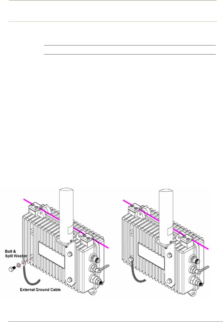
Procedure 1-5
Grounding APU enclosure
Action
Step Action
1. Check if an adequate grounding point is located as close to APU
unit so the effect of grounding can be maximized when any
transient or electrostatic discharge occurs to the unit.
2. Select one of four bolt holes not used at installation for unit
grounding.
3. Loosen the grounding bolt and wind the end of the ground wire
around the bolt.
4. Fasten a ground lug to the grounding point on the rear panel of
APU using a M6 bolt and split lock washer.
5. Strip adequate amount of wire jacket from the ends of the
grounding wire
6. Insert the stripped conductor into the compression area of the
grounding lug and tighten the bolt on the grounding lug.
7. Connect the opposite end of grounding wire to the grounding point
at a transmission facility.
Figure 2-16 Assembling the grounding bolt and wire
57
Access Point Unit: 2.4G-B-Radio-POE NTPM99AE 01 Rel 1.0 Issue1 May 2007
CSU Installation & Configuration
Mounting and Installation Concept
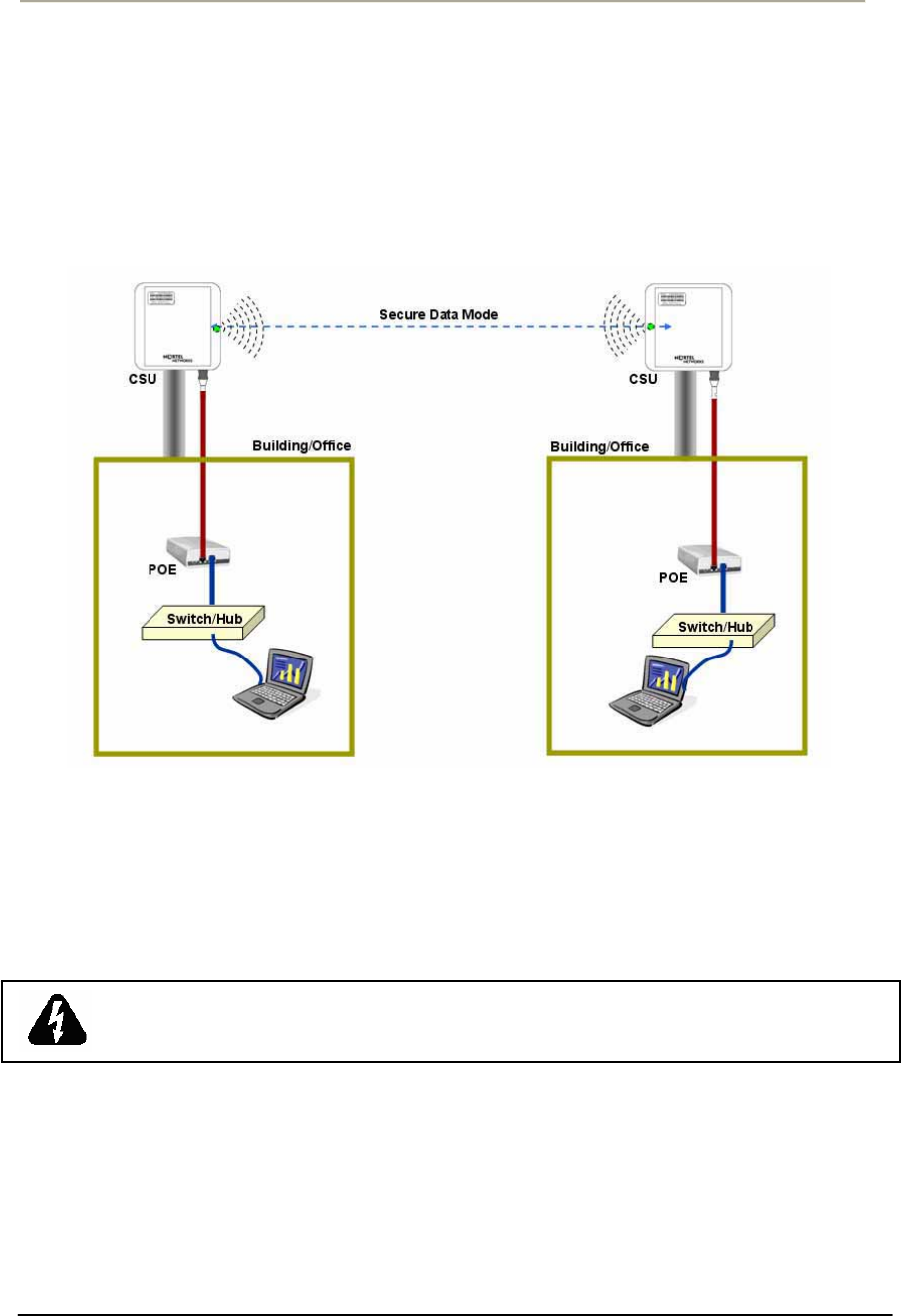
Figure 2-17 CSU Installation Concept on User’s facility
By default, CSU is pole mounted. Each unit is shipped with a pole
mounting module.
ENSURE THE CSU TO INSTALL SHALL BE POSITIONED NO LESS THAN 3
FEET ABOVE THE GROUND, OR FROM A ROUGHLY HORIZONTAL
SURFACE
.

58
Access Point Unit: 2.4G-B-Radio-POE NTPM99AE 01 Rel 1.0 Issue1 May 2007
Procedure 2-1
Site survey and Planning
Action
Step Action
1. List up a list of the parameters as below which are required to
calculate a radio link budget and RSL (Received Signal Level) as
well as a receiver sensitivity.
Pout: Transmitter Output Power of Radio card
Gtx: Transmitter antenna gain
Grx: Receiver antenna gain
Lct: Transmission loss between antenna and Transmitter module
Lcr: Transmission loss between antenna and Receiver module
FSL: Free space loss attenuation
2. Find the actual transmitter power associated with data rate and
channel number according to the Output Power tables in the
appendix A.
3. Calculate and determine the proper output power considering the
allowed Max EIRP (Effective Isotropic Radiated Power) in the
appendix A to comply with a regional radio regulatory rule.
Note: APU and CSU are certified as PMP system with the listed antenna
in the Appendix x. Therefore, to avoid any violation of radio regulation
and rules it is recommend to use the certified antennas in Appendix. x
4. Find a FSL value from the table according to a distance range(R)
between a transmitter and receiver and center frequency (F).
5. Calculate a RSL (Received Signal Level) with a formula and the
parameters using the formula (1) associated with this.
6. Find the receiver sensitivity for the data rate and transmit mode
from the Receiver Sensitivity in the appendix A.
7. Obtain a Fade margin (FM) by subtracting the receiver sensitivity
from the RSL (Received Signal Level).
Note: The large amount of FM(Fade Margin) indicates the high
reliability of radio system. Therefore, before he moves to the field
site, a system installer should keep in mind that a reliability of a radio
system depends on how much a fade margin is guaranteed.
8. If the FM result is very small or minus value, you need to enhance
the value by adjusting all parameters of radio unit or reducing the

59
Access Point Unit: 2.4G-B-Radio-POE NTPM99AE 01 Rel 1.0 Issue1 May 2007
distance value. But, the EIRP updated by adjusted parameters shall
be compliant to a radio regulatory rule.
Note: 10~15dB is recommended as a desirable FM value for APU
and CSU in a consideration of a various external condition like a
weather or at the installation.
Note: Please use the dedicated program, so called “Link budget
calculator” which provide a system installer with a convenient
solution for calculating a link budget and all system parameters.
9. Referring to the assured link parameter and system performance,
move to the site for installation and perform a site survey for the
service area.
10. Check if all pre-selected points are within the maximum coverage
in consideration of antenna type and data rate for a subscriber as
well as enough fade margin (over 10dB).
11. Although you fixed all system design parameters in an imaginary
calculation, actual performance will be different with the expected
one, depending on the interference factors related to “FRESONEL
Zone”.
12. For best performance, APU and CSU must be installed at the
location where it can achieve LOS (Line Of Sight) environment so
that there is no obstacles like tree and bulges in the direct path
between them.
13. Make sure that the link path between two units meet the clearance
condition as follows:
Cond.1: LOS (Line of Sight)
No obstacles in the direct path of antenna between APU and CSU.
Cond.2: OLOS (Optical Line of Sight)
No obstacles within the defined zone around the radio beam pattern,
so called “Fresnel Zone”
Note: The best means of achieving FRESNEL ZONE clearance is
raising the height of APU or CSU mounting point as high as possible.
14. Collect all information about RF signal quality and used channels
as well as interference at an install location by measuring a
portable spectrum analyzer or other signal measurement equipment.
15. Select an available channel for the unit considering antenna
coverage to avoid an interference with other radio systems.
16. Summarize the final setup parameter for the unit to install and
apply them to the configuration procedure described in the
following sections.
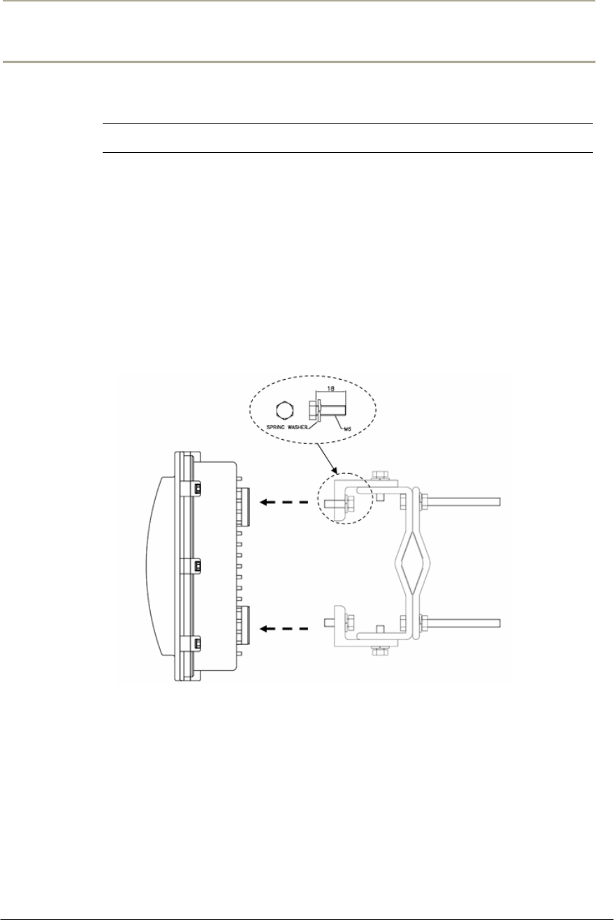
60
Access Point Unit: 2.4G-B-Radio-POE NTPM99AE 01 Rel 1.0 Issue1 May 2007
Procedure 2-2
Mounting the CSU on the pole and mast
Action
Step Action
1. Prior to an installation, check if the Pole has the strength and
stability to sustain the weight of CSU in a strong wind
2. Please find a mounting tool for installing CSU illustrated in Figure
3-30
3. Place the CSU face (RADOME side) down on a flat surface.
4. Using the mounting tool, attach the Mounting Tilt Brackets to the
back of CSU and insert the two stainless steel M6 hex head screws
and M6 split lock washers into the hole.
Figure 2-18 Assembling the mounting bracket on the CSU
5. Lift the CSU to a selected installation point on the pole and then
attach the clamp to the original location while lashing the CSU to
the pole or using a hoisting rope to keep the unit in place during
mounting work.
6. Slide two mounting nuts through a washer to each bracket hole as
illustrated in Figure 3-31
7. Adjust the azimuth of CSU Antenna RADOME toward the remote
unit and fasten sufficiently to secure the CSU on the pole.
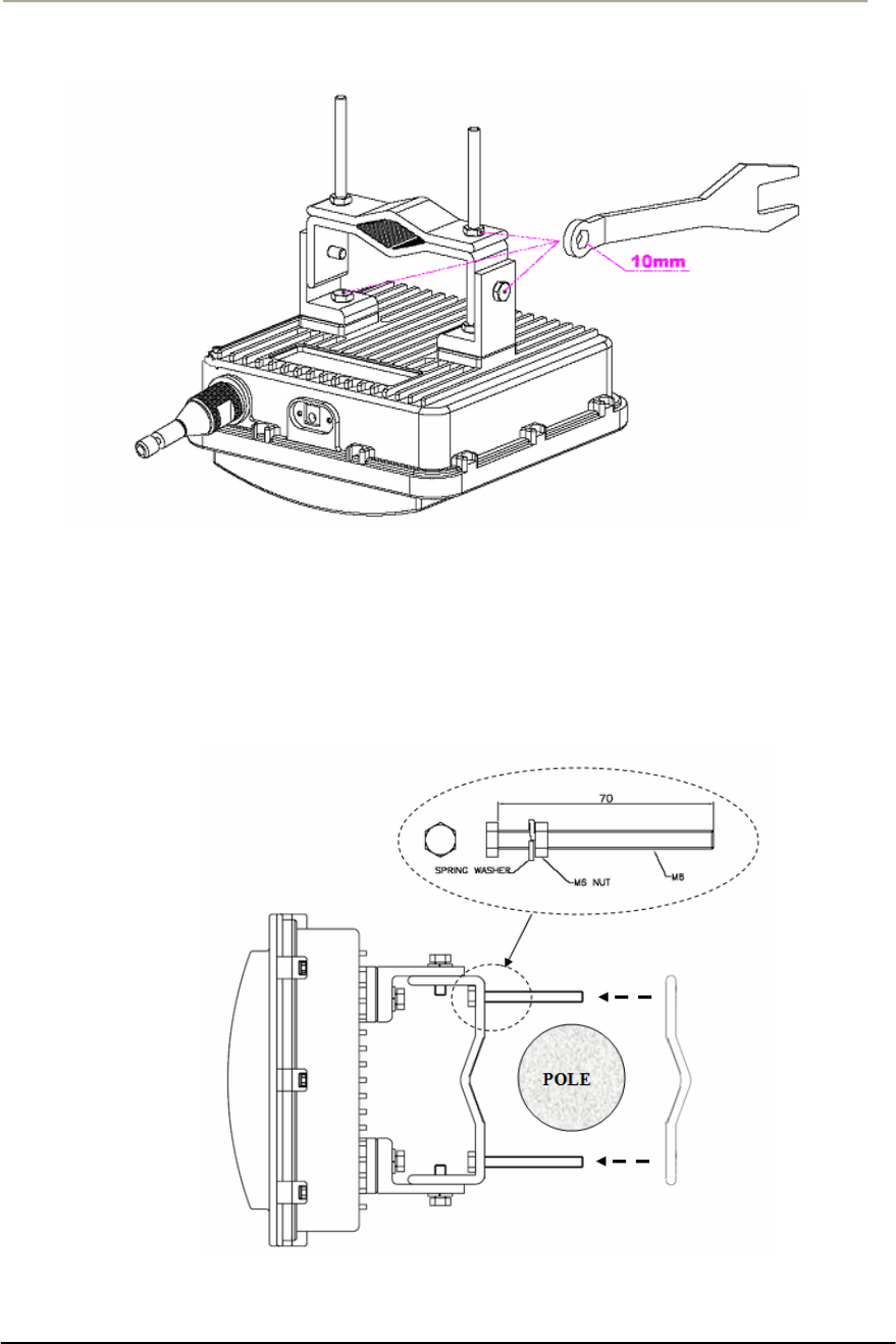
61
Access Point Unit: 2.4G-B-Radio-POE NTPM99AE 01 Rel 1.0 Issue1 May 2007
Figure 2-19 Assembling the mounting bracket with a installation tool
8. Adjust the up/down tilt (- 50 º to 50 º) and move the top or bottom
of the CSU until the unit is roughly positioned at the correct angle
and height.
Figure 2-20 CSU Pole Mounting and Antenna Tilting
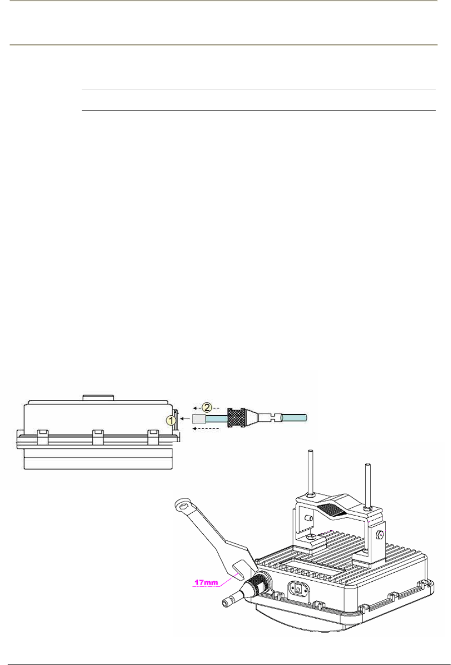
62
Access Point Unit: 2.4G-B-Radio-POE NTPM99AE 01 Rel 1.0 Issue1 May 2007
Procedure 2-3
Connecting to the CSU
Action
Step Action
1. Loosen the EMI cap and slide the CAT5 or 6 cables without the
RJ45 connector into the hole of the EMI hood shaped cap.
2. Follow the conventional procedure of creating a CAT5 or 6
Ethernet cable.
Note: It is recommended to use a shielded cable like S-FTP(Foiled
Twisted Pair) or STP (Shielded Twisted Pair) in which wire pairs are
covered with overall shield material to prevent EMI effects to or from the
near electronic devices or facilities.
Note: The cable from CSU to POE Injector and from POE Injector to
CPE (PC) should be a straight-through cable.
3. Connect a cable to the POE port on the front panel of CSU through
the hole of EMI cap and tighten it firmly.
Figure 2-21 Connecting Ethernet Cable to CSU and Securing the EMI Cap
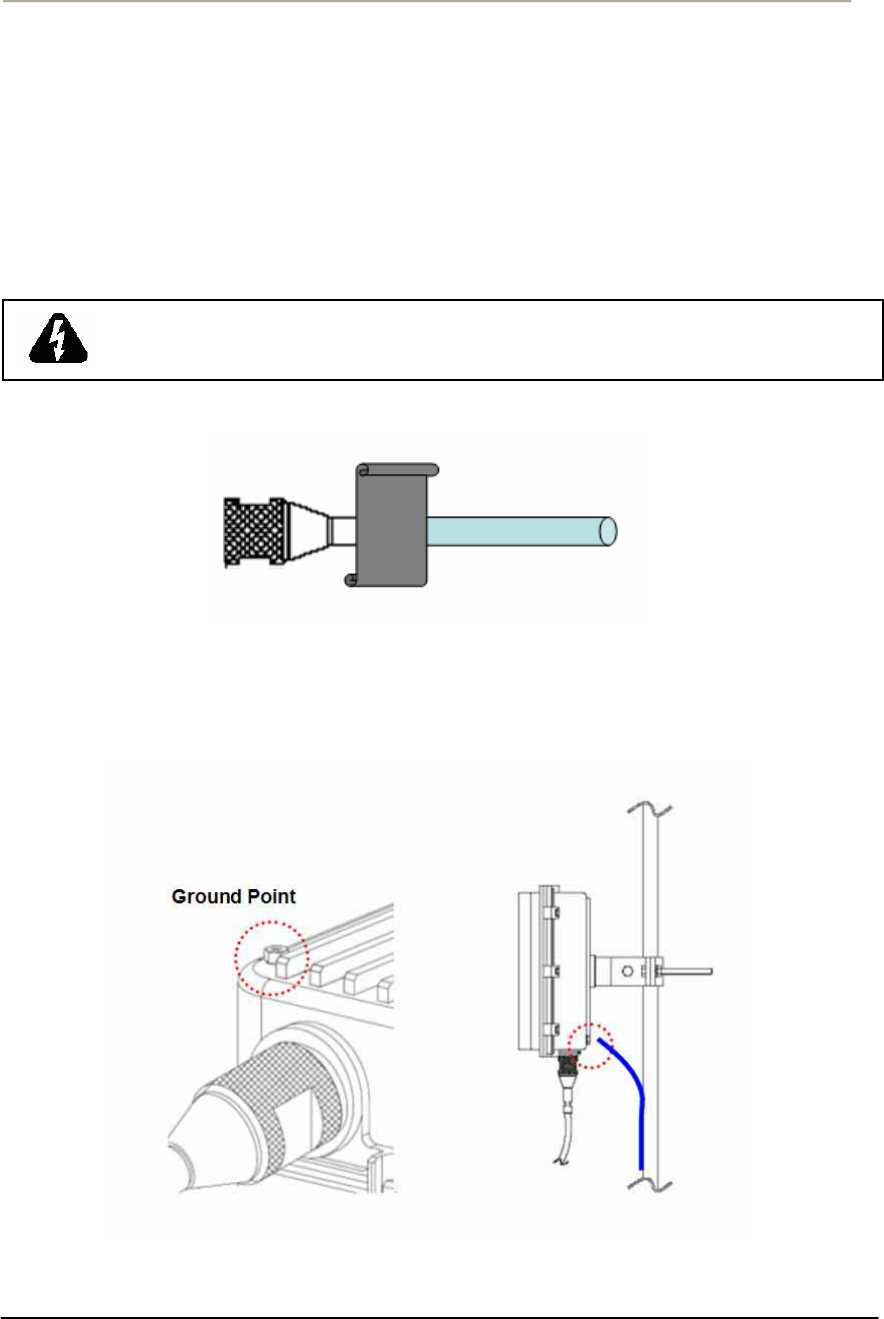
63
Access Point Unit: 2.4G-B-Radio-POE NTPM99AE 01 Rel 1.0 Issue1 May 2007
4. Secure the cable in the EMI cap by tightening it with a cable tie.
Cover the connectors with black self amalgamating tape or shrink
wrap tubing to ensure a waterproof seal. This is the most crucial
step in the installation. If this procedure is disregarded or done
insufficiently an unexpected system fault could occur in a normal
operation and affect on the system performance factor relevant to
the long term reliability.
5. Tighten the EMI cap securely with the special tool packaged in the
product box.
Figure 2-22 Protecting EMI Cap and Shielded Cable with Tape or shrink wrap tubing
6. Connect the ground wire to the ground point at the lower right end
of CSU back panel.
Figure 2-23 Connecting the ground wire to the ground point
WHEN INSTALLING THE UNIT, CHOOSE A LOCATION THAT PROVIDES A
MINIMUM SEPARATION OF 20 cm FROM ALL PERSONS DURING NORMAL
OPERATION.
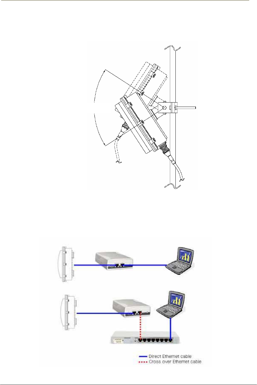
64
Access Point Unit: 2.4G-B-Radio-POE NTPM99AE 01 Rel 1.0 Issue1 May 2007
7. Adjust the tilt and height of antenna so that the beam path can
achieve the maximum clearance condition in consideration of
FRESNEL ZONE and Earth bulge effect.
Figure 2-24 Adjusting the tilt and height
8. Connect the other end of the data cable to the POE Injector indoor.
9. Plug the power cord of the POE Injector into an electrical outlet
Figure 2-25 Connecting CSU and User PC by an Ethernet Cable though POE Injector
100
º

65
Access Point Unit: 2.4G-B-Radio-POE NTPM99AE 01 Rel 1.0 Issue1 May 2007
Mounting Tips
xVerify the Line-of-Sight -- Before installing CSU, make sure a clear line-of-
sight exists. Line of sight (LOS) can be defined as each antenna clearly
seeing the other antenna, and seeing the remote locations when viewing from
the central base location. Be sure to look level with the center of origin of the
transmission (i.e., the middle of the antenna). Repeat this procedure from the
remote location. Any disruption of the signal path due to trees, buildings, or
any other obstructions may cause the link to function incorrectly. If you see
any obstructions between two antennas, move one or both antennas to
another location.
xUse mounting hardware provided to secure the unit to the pole.
xLeave the unit mounting loose enough to allow for movement when
performing the alignment/testing procedure. The unit should be tightened
only after the alignment/testing procedure is completed.
xInstall the unit away from microwave ovens and 2.4 GHz cordless phones.
Microwave ovens and some cordless phones operate on the same frequency
as the unit and can cause signal interference.
xBegin at the lowest point, so the tape overlaps from bottom to top creating a
shingled effect. This creates an effective barrier against water runoff. Apply
this "shingle effect" to each layer of the sealing process. Apply two layers of
electrical tape to the connector, and leave approximately 3 inches of cable
exposed on either side of the connector.

66
Access Point Unit: 2.4G-B-Radio-POE NTPM99AE 01 Rel 1.0 Issue1 May 2007
Configuration
WLAN Cable Access Point 6220 CSU (APU, CSU) has the following
management and operational features listed below:
APU-APU mode Basic Configuration and Operation Test
CSU-APU mode Basic Configuration and Operation Test
CSU-CSU mode Basic Configuration and Operation Test
Testing the connection between APU & CSU (APU mode) and CSU
Testing Wireless Network Performance
Basic Configuration
Advanced and Optional Configuration

67
Access Point Unit: 2.4G-B-Radio-POE NTPM99AE 01 Rel 1.0 Issue1 May 2007
Procedure 3-1
Basic configuration and Operation Test (APU-APU Mode)
Action
Step Action
1. The APU has the following factory default parameters:
Factory Default
IP address: DHCP Client (Ethernet 1)
Read Write Password: public
IEEE 802.11 Interface Setup
- Mode Selection: APU SDM(Secure Data Mode)
- Base station mode: Polling (Primary)
- Frequency
Æ 802.11b Unit: CH1 (2412 MHz)
- Network ID: 1
- Transmit Rate
Æ 802.11b Unit: 11Mbps
- WEP Encryption: Disable
2. The CSU (CSU mode) shall have the same system parameters with
a factory default parameter of APU to install.
Table 3-1 System Main Parameters
Parameter APU/CSU(APU mode) CSU
IP address DHCP Client DHCP Client
Read Write Password Public Public
SNMP Secure
Configuration Password
Public Public
Mode Selection APU Secure Data Mode CSU Secure Data Mode
Base Station Mode Polling(Primary) N/A
Frequency User specific User specific
Transmit Rate User specific User specific
Network ID 0 0
Others User-specific User-specific
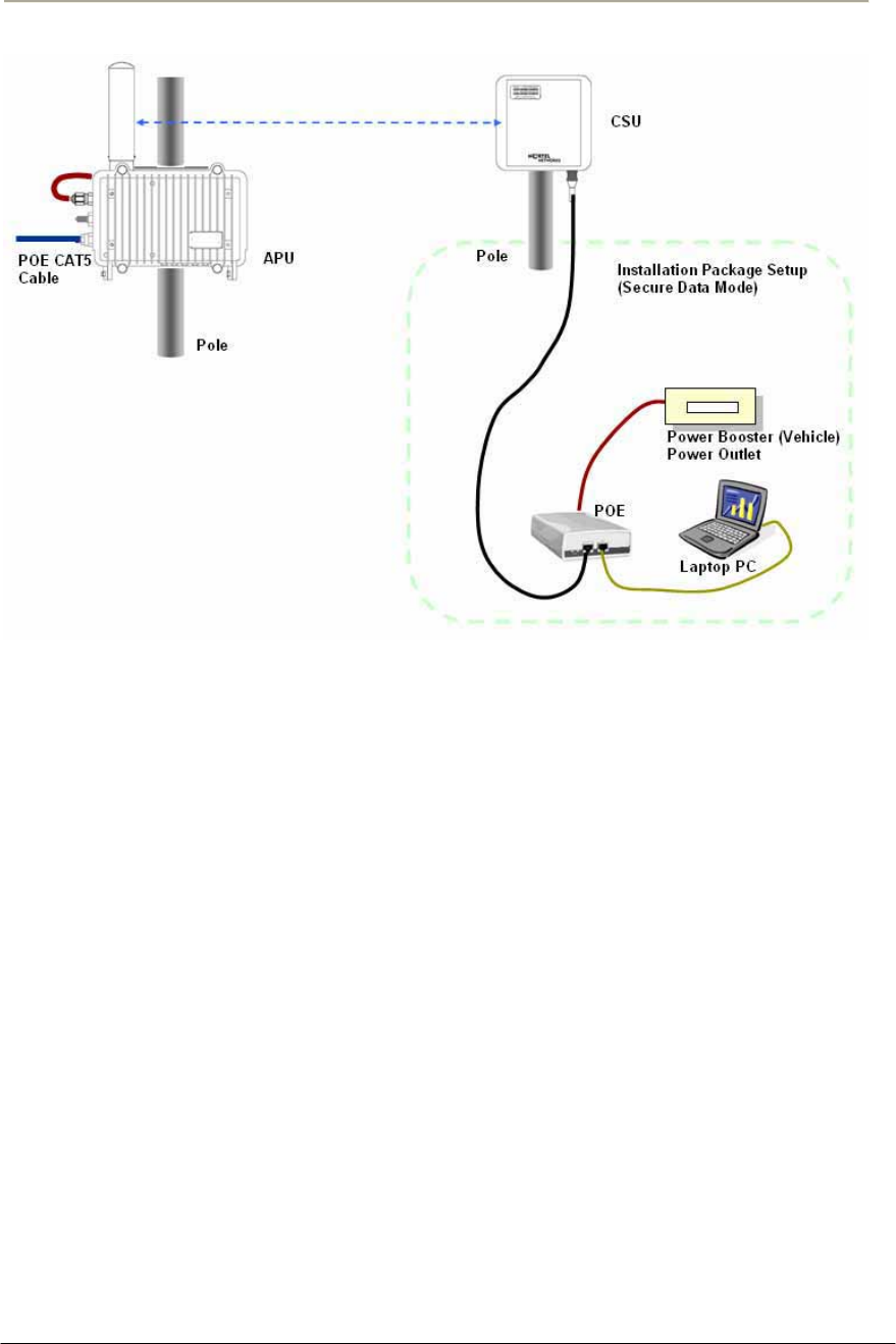
68
Access Point Unit: 2.4G-B-Radio-POE NTPM99AE 01 Rel 1.0 Issue1 May 2007
Figure 3-1 Test Network Configuration (Radio Connection)
3. Prepare a Laptop computer and a client unit to test and configure
the CSU at the installation location.
4. Connect Laptop PC to CSU Ethernet port with a straight-forward
cable to setup.
5. Launch the Configurator by either double clicking the WLAN
Cable AP Configurator icon on your desktop or by opening the file
config.exe from the directory “C:\Program Files\Nortel\WLAN
Cable AP Configurator” where software is installed at.
6. Run the Configurator and the IP Address for your APU (and the IP
addresses for any other devices in your network) as appears in the
Configurator window below.
Note: In factory default, APU and CSU have a default IP address as
“198.17.74.254” regardless of the software modes (APU, CSU mode),
which means that APU and CSU are ready to get it’s IP address from a
remote DHCP Server. Therefore, when you launch AP configurator at
PC with CSU turned on at first, you can find the default IP address of the
CSU showing the green exclamation point “198.17.74.254” in the List of
Scanned Devices window. In case that DHCP service is available in the
network, you can find a new local IP address assigned to the unit from
DHCP server in the list box except the default IP address.
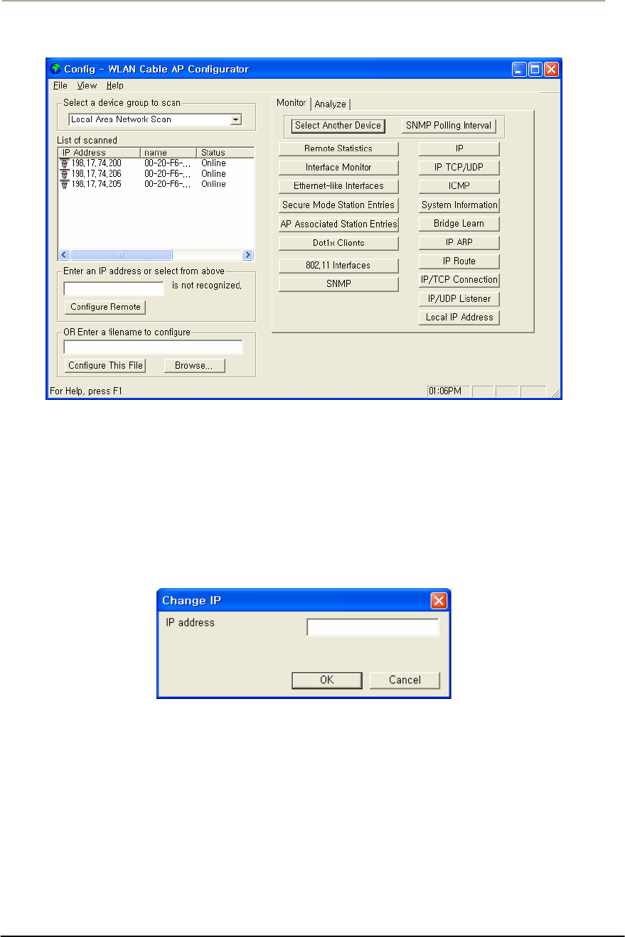
69
Access Point Unit: 2.4G-B-Radio-POE NTPM99AE 01 Rel 1.0 Issue1 May 2007
Figure 3-2 Configurator Starting Window
7. In case you want to forcibly setup IP address, follow this
procedure as below.
8. Right click on the IP address of CSU, and then select ‘Configure
This Device’. or click “Configure Remote” button below the list
box.
9. The Change IP window is displayed, as shown in the following
screenshot.
Figure 3-3 IP setup dialog box
10. Enter an IP address that will be local to the IP of the PC/laptop
running the Configurator, and then click the OK button in Read
Write Password window.
Note: The IP address to enter should be included in the same subnet area
with PC/Laptop computer for access to CSU.
For example, in case the IP address of Laptop computer is
192.168.0.100/24, the CSU will be allowable in 192.168.0.1/24 ~
192.168.0.254/24 as the IP address subnet group.
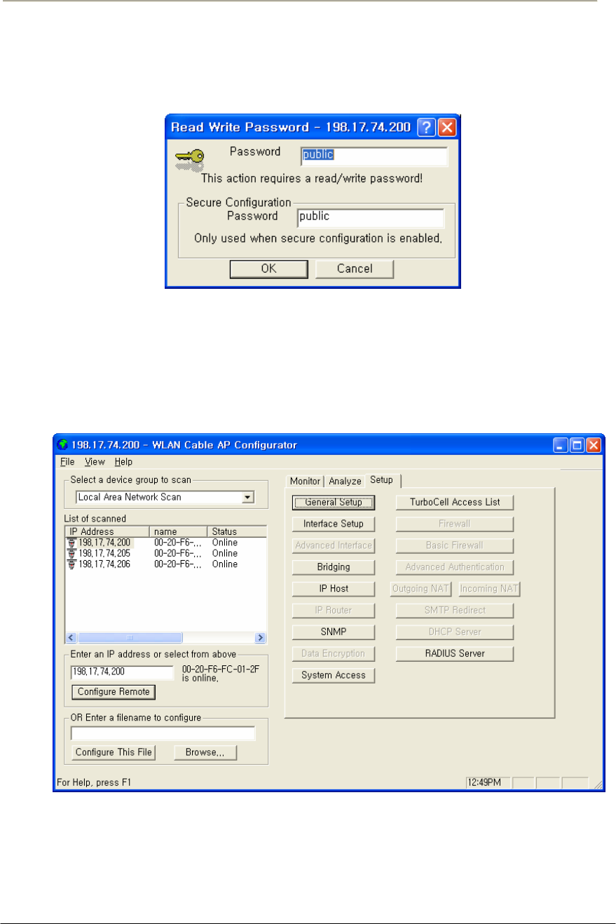
70
Access Point Unit: 2.4G-B-Radio-POE NTPM99AE 01 Rel 1.0 Issue1 May 2007
11. The SNMP Password dialog box is displayed, as shown below.
12. Press “Enter” key or enter a new password instead of the default
password “public” in the basic SNMP password box.
Figure 3-4 SNMP Read Write Password dialog box
13. The main window is redisplayed.
14. To setup the interface, Click on the Interface Setup button.
15. The Interface Setup screen is enabled and displayed, as shown in
the Figure 3-6
Figure 3-5 AP Configurator Main window
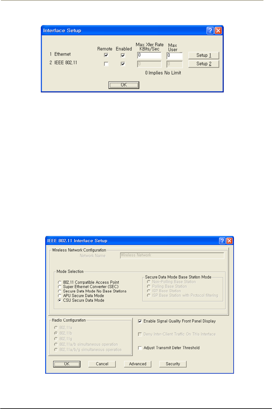
71
Access Point Unit: 2.4G-B-Radio-POE NTPM99AE 01 Rel 1.0 Issue1 May 2007
Figure 3-6 Interface setup dialog box
16. If you have an 802.11 radio card, click the Setup 2 button to set up
the 802.11 interface.
17. Click the Setup 2 button. The IEEE 802.11 Setup screen is
displayed, as shown in Figure 3-6
18. Select a radio standard to use according to the built-in antenna
specification like an operating frequency range.
Ex) 2.4GHz antenna : 802.11b/g
19. Make sure the APU Secure Data Mode in the left portion of Mode
Selection is selected while “Polling Base station” is clicked in
Secure Data Mode Base Station Mode.
20. Select the Enable Signal Quality Front Panel Display checkbox if
your unit has a front panel display that is capable of displaying the
signal quality.
Figure 3-7 Interface setup dialog box
21. Click on the advanced button to set up crucial parameters such as
Radio Frequency, Transmit Rate (Bandwidth) and Network ID.
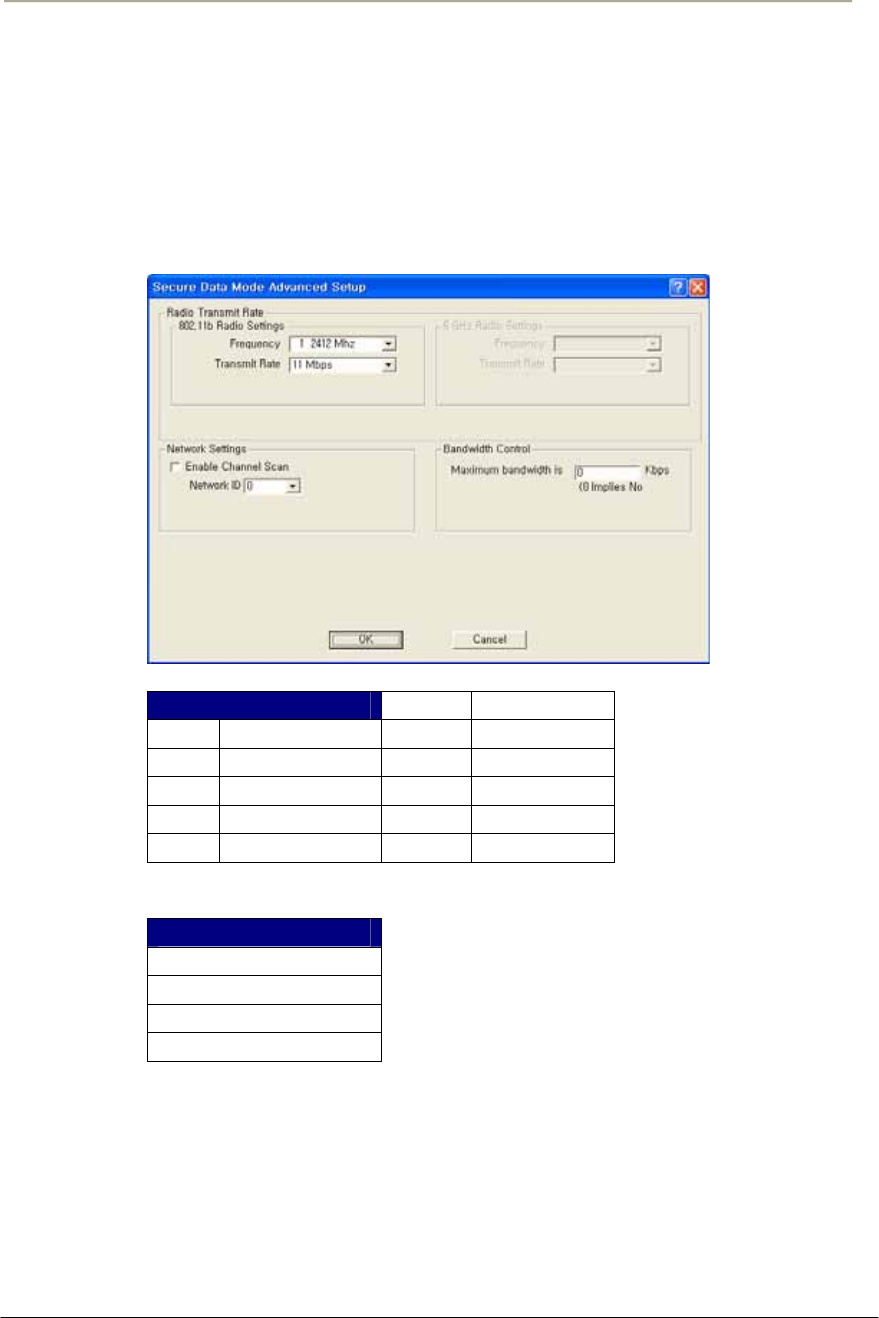
72
Access Point Unit: 2.4G-B-Radio-POE NTPM99AE 01 Rel 1.0 Issue1 May 2007
22. The Advanced Setup screen for a Secure Data Mode is shown
below.
23. Setup all radio parameters including a frequency channel and
transmit power referring to the permitted setting value specified in
the following tables per radio standard.
Figure 3-8 Advanced setup dialog box
[802.11b]
Frequency Channel 6 2437 MHz
1 2412 MHz 7 2442 MHz
2 2417 MHz 8 2447 MHz
3 2422 MHz 9 2452 MHz
4 2427 MHz 10 2457 MHz
5 2432 MHz 11 2462 MHz
Transmit Rate
11 Mbps
5.5 Mbps
2 Mbps
1 Mbps

73
Access Point Unit: 2.4G-B-Radio-POE NTPM99AE 01 Rel 1.0 Issue1 May 2007
Caution:Do not use any other antennas exceeding the allowed
maximum gain per each antenna type in case you select 802.11b/g mode.
For example, if you are intended to use omni-directional antenna for
APU, it is illegal that you use a similar type of antenna with 14dBi even
though the max allowable antenna is up to 14dBi.
Make sure that a gain per antenna type does not exceed the certified
value.
Note: The channel/frequency values are usually determined by network
administrators. If you set the channel and frequency in 802.11b/g, ensure
that there are at least four numerical channel differences between two
overlapping cells to avoid interference. For example, channels 1, 6 and
11 don’t overlap, but channels 1 and 3 do.
In the other side, if you are intended to use 802.11a, please keep in mind
that all channels (4 channels) with 20MHz bandwidth are not permitted
to be overlapped with each channels in the frequency plan.
Note: It is recommended that you set the transmit power to “Maximum”
as the antennas listed in Appendix B(Antenna) have been designed to
meet FCC regulation specifying the maximum allowable EIRP at the
maximum transmit power.
24. Select the Network ID in Network Settings referring to Figure 3-
12 “Wireless Network Planning."
Note: the Secure Data Mode network ID number (0-15) is used to
differentiate between multiple Secure Data Mode stations using the same
System Access Pass Phrase. This is used to allow a Secure Data Mode
CSU to specify the APU mode unit that it wants to connect to if two
APU mode units can be seen by the same CSU. Generally, this value
should be the same as the Channel Number.
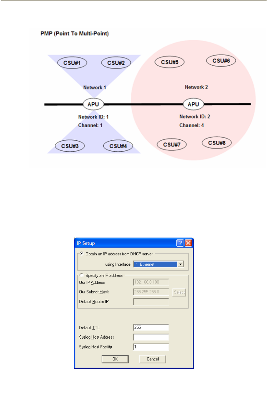
74
Access Point Unit: 2.4G-B-Radio-POE NTPM99AE 01 Rel 1.0 Issue1 May 2007
Figure 3-9 Wireless Network Planning
25. Click “OK” button.
26. Click the Setup Æ IP Setup button. The IP Setup screen is
displayed, as shown below.
Figure 3-10 IP setup dialog box
Note: The IP Setup screen allows you to set the Secure Data Mode
Station's IP Addressing information. The Secure Data Mode Station must
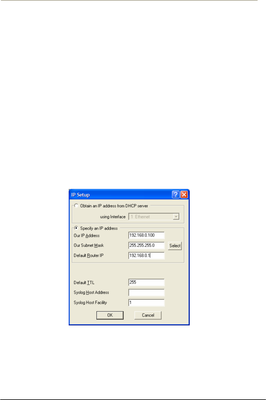
75
Access Point Unit: 2.4G-B-Radio-POE NTPM99AE 01 Rel 1.0 Issue1 May 2007
have an IP address assigned to it if you wish to connect to it using the
Configurator tool, which makes use of SNMP to connect to the Secure
Data Mode Station.
27. Select “Specify an IP address” and type a specific IP address and
gateway IP address. Click OK button.
Note: Except for cable modem built-in APU, the CSU to operate as APU
mode is required to set a mandatory static IP address for the unit even
though it can be set in both static IP and DHCP setup. But, you can set
DHCP mode to the CSU (APU mode) so that it can retrieve its IP
address from a remote or local DHCP server.
Note: For DHCP client mode, select “1 Ethernet” as the interface which
is used to get DHCP IP address from DHCP Server.
Note: If you select the DHCP option, it is recommended (though not
required) that you set up your DHCP server to always provide the same
IP address to this Secure Data Mode Station system.
Figure 3-11 IP setup dialog box
28. For a more detailed setup, refer to the procedure 3-5(Basic
Configuration) and 3-6(Advanced and Optional Configuration).

76
Access Point Unit: 2.4G-B-Radio-POE NTPM99AE 01 Rel 1.0 Issue1 May 2007
Procedure 3-2
Basic configuration and Operation Test (CSU-APU Mode)
Action
Step Action
1. The CSU(APU mode) has the following factory default
parameters:
Factory Default
IP address: DHCP Client (Ethernet 1)
Read Write Password: public
SNMP Secure Configuration Password: public
IEEE 802.11 Interface Setup
- Mode Selection: APU SDM(Secure Data Mode)
- Base station mode: Polling (Primary)
- Frequency
Æ 802.11b Unit: CH1 (2412 MHz)
- Network ID: 1
- Transmit Rate
Æ 802.11b Unit: 11Mbps
- WEP Encryption: Disable
2. The CSU (CSU mode) shall have the same system parameters with
a factory default parameter of APU to install.
Table 3-2 System Main Parameters
Parameter APU/CSU(APU mode) CSU
IP address DHCP Client DHCP Client
Read Write Password Public Public
Mode Selection APU Secure Data Mode CSU Secure Data Mode
Base Station Mode Polling(Primary) N/A
Frequency User specific User specific
Transmit Rate User specific User specific
Network ID 0 0
Others User-specific User-specific
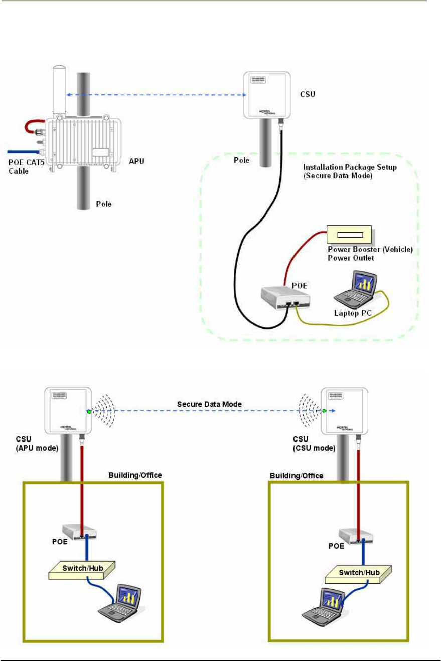
77
Access Point Unit: 2.4G-B-Radio-POE NTPM99AE 01 Rel 1.0 Issue1 May 2007
Figure 3-12 Test Network Configuration (Radio Connection)
[Case I] APU to CSU (PTP or PMP)
[Case II] CSU to CSU (PTP or PMP)
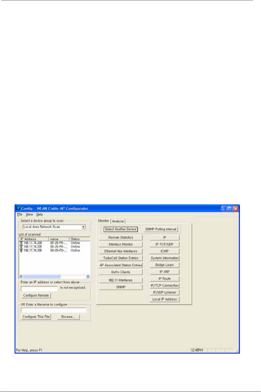
78
Access Point Unit: 2.4G-B-Radio-POE NTPM99AE 01 Rel 1.0 Issue1 May 2007
3. Prepare a Laptop computer and a client unit to test and configure
the CSU at the installation location.
4. Connect Laptop PC to CSU Ethernet port with a straight-forward
cable to setup.
5. Launch the Configurator by either double clicking the WLAN
Cable AP Configurator icon on your desktop or by opening the file
config.exe from the directory “C:\Program Files\Nortel\WLAN
Cable AP Configurator” where software is installed at.
6. Run the Configurator and the IP Address for your APU (and the IP
addresses for any other devices in your network) as appears in the
Configurator window below.
Note: In factory default, APU and CSU have a default IP address as
“198.17.74.254” regardless of the software modes (APU, CSU mode),
which means that APU and CSU are ready to get it’s IP address from a
remote DHCP Server. Therefore, when you launch AP configurator at
PC with CSU turned on at first, you can find the default IP address of the
CSU showing the green exclamation point “198.17.74.254” in the List of
Scanned Devices window. In case that DHCP service is available in the
network, you can find a new local IP address assigned to the unit from
DHCP server in the list box except the default IP address.
Figure 3-13 Configurator Starting Window
7. Right click on the IP address of CSU, and then select ‘Configure
This Device’. or click “Configure Remote” button below the list
box.
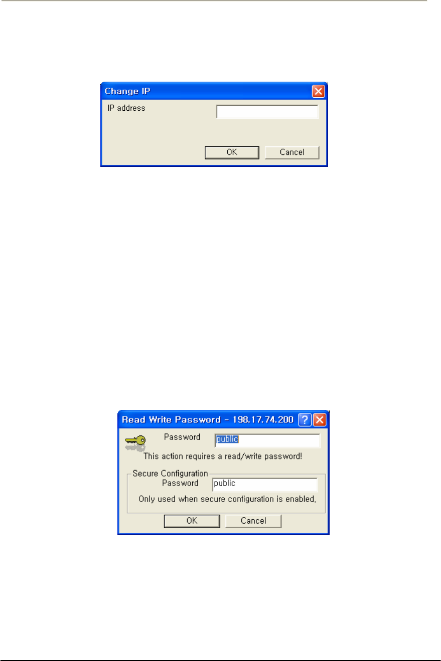
79
Access Point Unit: 2.4G-B-Radio-POE NTPM99AE 01 Rel 1.0 Issue1 May 2007
8. The Change IP window is displayed, as shown in the following
screenshot.
Figure 3-14 IP setup dialog box
9. Enter an IP address that will be local to the IP of the PC/laptop
running the Configurator, and then click the OK button in Read
Write Password window.
Note: The IP address to enter should be included in the same subnet area
with PC/Laptop Computer for access to CSU.
For example, in case the IP address of Laptop computer is
192.168.0.100/24, the CSU will be allowable in 192.168.0.1/24 ~
192.168.0.254/24 as the IP address subnet group.
10. The SNMP Password dialog box is displayed, as shown below.
11. Press “Enter” key or enter a new password instead of the default
password “public” in the basic SNMP password box.
Figure 3-15 SNMP Read Write Password dialog box
12. The main window is redisplayed.
13. To setup the interface, Click on the Interface Setup button.
14. The Interface Setup screen is enabled and displayed, as shown in
the Figure 3-16
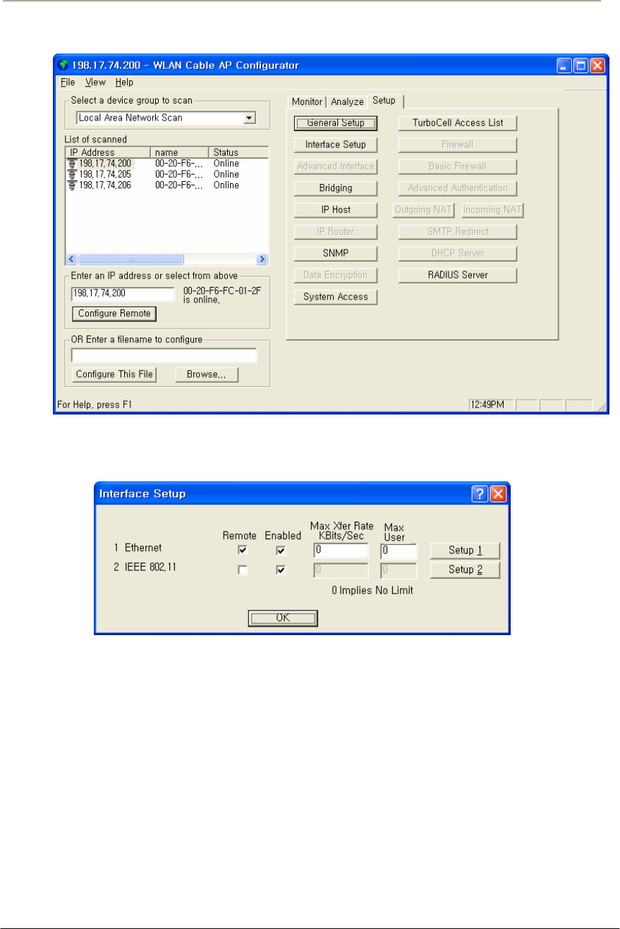
80
Access Point Unit: 2.4G-B-Radio-POE NTPM99AE 01 Rel 1.0 Issue1 May 2007
Figure 3-16 AP Configurator Main window
Figure 3-17 Interface setup dialog box
15. If you have an 802.11 radio card, click the Setup 2 button to set up
the 802.11 interface.
16. Click the Setup 2 button. The IEEE 802.11 Setup screen is
displayed, as shown in Figure 3-17
17. Select a radio standard to use according to the built-in antenna
specification like an operating frequency range.
Ex) 2.4GHz antenna : 802.11b
18. Make sure the APU Secure Data Mode in the left portion of Mode
Selection is selected while “Polling Base station” is clicked in
Secure Data Mode Base Station Mode.
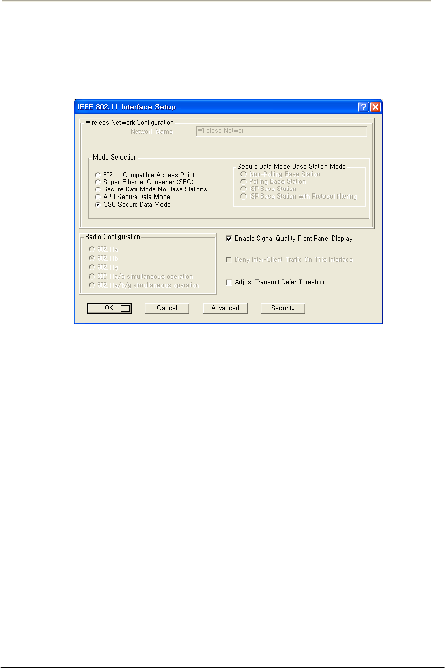
81
Access Point Unit: 2.4G-B-Radio-POE NTPM99AE 01 Rel 1.0 Issue1 May 2007
19. Select the Enable Signal Quality Front Panel Display checkbox if
your unit has a front panel display that is capable of displaying the
signal quality.
Figure 3-18 Interface setup dialog box
20. Click on the advanced button to set up crucial parameters such as
Radio Frequency, Transmit Rate (Bandwidth) and Network ID.
21. The Advanced Setup screen for a Secure Data Mode is shown
below.
22. Setup all radio parameters including a frequency channel and
transmit power referring to the permitted setting value specified in
the following tables per radio standard.
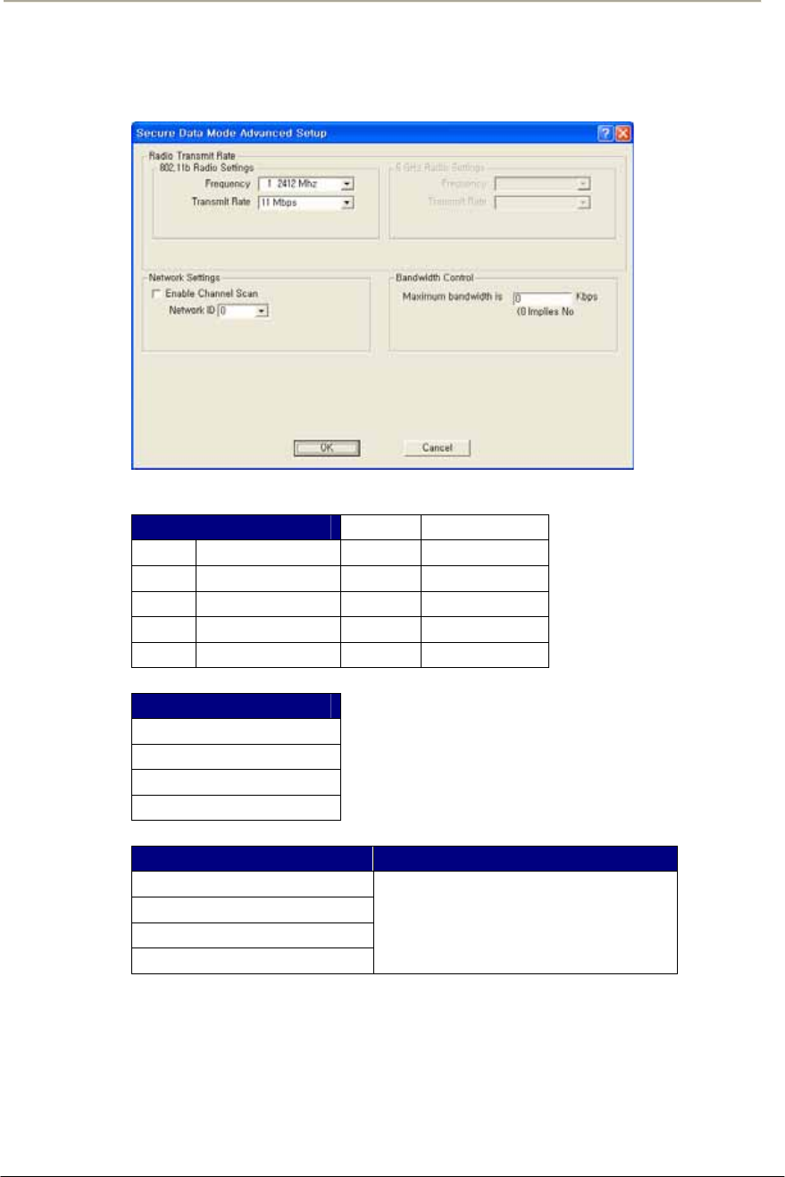
82
Access Point Unit: 2.4G-B-Radio-POE NTPM99AE 01 Rel 1.0 Issue1 May 2007
Figure 3-19 Advanced setup dialog box
[802.11b]
Frequency Channel 6 2437 MHz
1 2412 MHz 7 2442 MHz
2 2417 MHz 8 2447 MHz
3 2422 MHz 9 2452 MHz
4 2427 MHz 10 2457 MHz
5 2432 MHz 11 2462 MHz
Transmit Rate
11 Mbps
5.5 Mbps
2 Mbps
1 Mbps
Transmit Power Antenna Gain
Maximum
50%
25%
12.5%
Maximum allowable antenna
Gain(CSU/11B): 12dBi
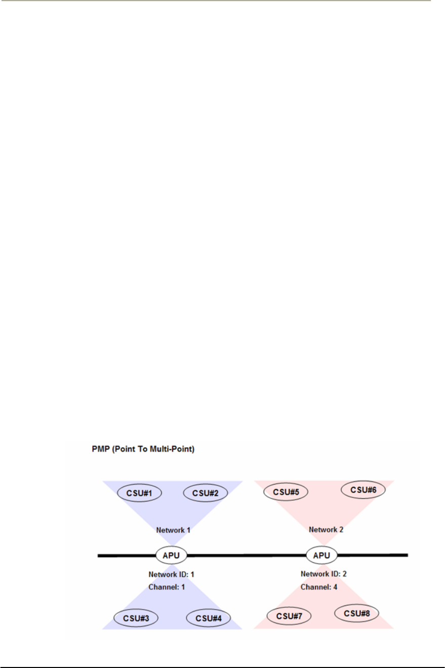
83
Access Point Unit: 2.4G-B-Radio-POE NTPM99AE 01 Rel 1.0 Issue1 May 2007
Caution:Do not use any other antennas exceeding the allowed
maximum antenna gain value (12dBi) except as the built-in type of
antenna (ET-PR12) designated in Appendix B (Antenna) in case you
select 802.11b/g mode as operation radio standard.
Note: The channel/frequency values are usually determined by network
administrators. If you set the channel and frequency in 802.11b/g, ensure
that there are at least four numerical channel differences between two
overlapping cells to avoid interference. For example, channels 1, 6 and
11 don’t overlap, but channels 1 and 3 do.
In the other side, if you are intended to use 802.11a, please keep in mind
that all channels (4 channels) with 20MHz bandwidth are not permitted
to be overlapped with each channels in the frequency plan.
Note: It is recommended that you set the transmit power to “Maximum”
as the antenna (ET-PR12) have been designed to meet FCC regulation
specifying the maximum allowable EIRP at the maximum transmit
power.
23. Select the Network ID in Network Settings referring to Figure 3-
20 “Wireless Network Planning”
Note: the Secure Data Mode network ID number (0-15) is used to
differentiate between multiple Secure Data Mode stations using the same
System Access Pass Phrase. This is used to allow a Secure Data Mode
CSU to specify the APU mode unit that it wants to connect to if two
APU mode units can be seen by the same CSU. Generally, this value
should be the same as the Channel Number.
Figure 3-20 Wireless Network Planning
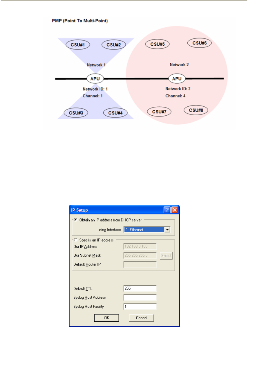
84
Access Point Unit: 2.4G-B-Radio-POE NTPM99AE 01 Rel 1.0 Issue1 May 2007
24. Click “OK” button.
Click the Setup Æ IP Setup button. The IP Setup screen is displayed, as
shown below.
Figure 3-21 IP setup dialog box
Note: The IP Setup screen allows you to set the Secure Data Mode
Station's IP Addressing information. The Secure Data Mode Station must
have an IP address assigned to it if you wish to connect to it using the
Configurator tool, which makes use of SNMP to connect to the Secure
Data Mode Station.
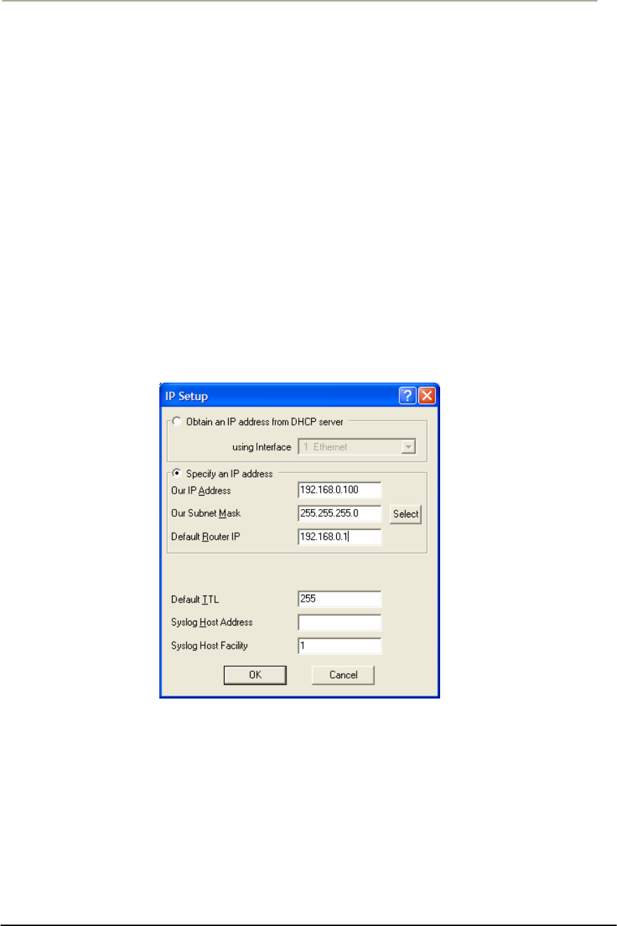
85
Access Point Unit: 2.4G-B-Radio-POE NTPM99AE 01 Rel 1.0 Issue1 May 2007
25. Select “Specify an IP address” and type a specific IP address and
gateway IP address. Click OK button.
Note: Except for cable modem built-in APU, the CSU to operate as APU
mode is required to set a mandatory static IP address for the unit even
though it can be set in both static IP and DHCP setup. But, you can set
DHCP mode to the CSU (APU mode) so that it can retrieve its IP
address from a remote or local DHCP server.
Note: For DHCP client mode, select “1 Ethernet” as the interface which
is used to get DHCP IP address from DHCP Server.
Note: If you select the DHCP option, it is recommended (though not
required) that you set up your DHCP server to always provide the same
IP address to this Secure Data Mode Station system.
Figure 3-22 IP setup dialog box
26. For a more detailed setup, refer to the procedure 3-5(Basic
Configuration) and 3-6(Advanced and Optional Configuration).

86
Access Point Unit: 2.4G-B-Radio-POE NTPM99AE 01 Rel 1.0 Issue1 May 2007
Procedure 3-3
Basic configuration and Operation Test (CSU-CSU Mode)
Action
Step Action
1. The CSU(CSU mode) has the following factory default
parameters:
Factory Default
IP address: DHCP Client (IEEE 802.11 2)
Read Write Password: public
IEEE 802.11 Interface Setup
- Mode Selection: CSU SDM(Secure Data Mode)
- Base station mode: N/A
- Frequency
Æ 802.11b Unit: CH1 (2412 MHz)
- Network ID: 1
- Transmit Rate
Æ 802.11b Unit: 11Mbps
2. The CSU (CSU mode) shall have the common system parameters
with that of a factory default parameter of APU to install.
Table 3-3 System Main Parameters
Parameter CSU(APU mode) CSU(CSU mode)
IP address DHCP Client DHCP Client
Read Write Password Public Public
SNMP Secure
Configuration Password
Public Public
Mode Selection APU Secure Data Mode CSU Secure Data Mode
Base Station Mode Polling(Primary) N/A
Frequency User specific User specific
Transmit Rate User specific User specific
Network ID 0 0
Others User-specific User-specific
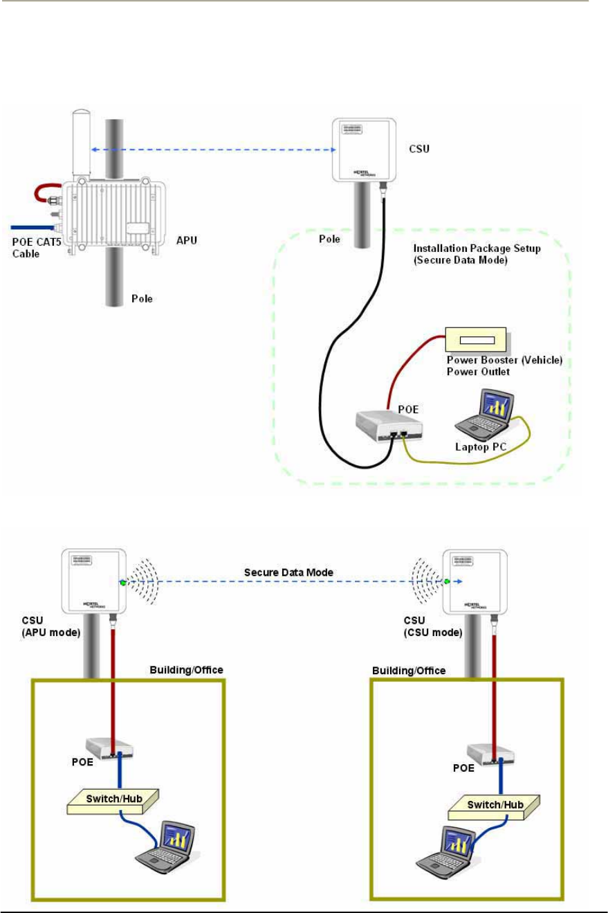
87
Access Point Unit: 2.4G-B-Radio-POE NTPM99AE 01 Rel 1.0 Issue1 May 2007
Figure 3-23 Test Network Configuration (Radio Connection)
[Case I] APU to CSU (PTP or PMP)
[Case II] CSU to CSU (PTP or PMP)
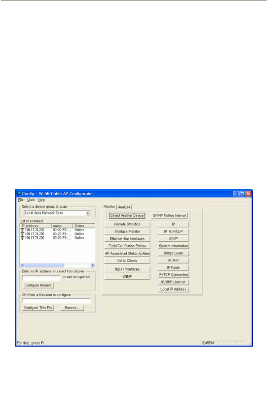
88
Access Point Unit: 2.4G-B-Radio-POE NTPM99AE 01 Rel 1.0 Issue1 May 2007
3. Prepare a Laptop computer and a client unit to test and configure
the CSU at the installation location.
4. Connect Laptop PC to CSU Ethernet port with a straight-forward
cable to setup.
5. Launch the Configurator by either double clicking the WLAN
Cable AP Configurator icon on your desktop or by opening the file
config.exe from the directory “C:\Program Files\Nortel\WLAN
Cable AP Configurator” where software is installed at.
6. Run the Configurator and the IP Address for your APU (and the IP
addresses for any other devices in your network) as appears in the
Configurator window below.
Note: In factory default, the CSU have a default IP address as
“198.17.74.254” regardless of the software modes (APU, CSU mode).
Therefore, when you launch AP configurator at PC with CSU turned on
at first, you can find the default IP address of the CSU showing the green
exclamation point “198.17.74.254” in the List of Scanned Devices
window showing the green exclamation point”198.17.74.254”.
Figure 3-24 Configurator Starting Window
7. Right click on the IP address of CSU, and then select ‘Configure
This Device’. or click “Configure Remote” button below the list
box.
8. The Change IP window is displayed, as shown in the following
screenshot.
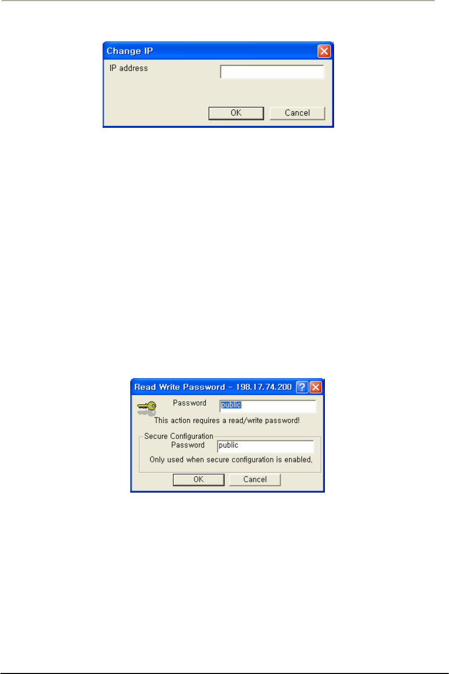
89
Access Point Unit: 2.4G-B-Radio-POE NTPM99AE 01 Rel 1.0 Issue1 May 2007
Figure 3-25 IP setup dialog box
9. Enter an IP address that will be local to the IP of the PC/laptop
running the Configurator, and then click the OK button in Read
Write Password window.
Note: The IP address to enter should be included in the same subnet area
with PC/Laptop Computer for access to CSU.
For example, in case the IP address of Laptop computer is
192.168.0.100/24, the CSU will be allowable in 192.168.0.1/24 ~
192.168.0.254/24 as the IP address subnet group.
10. The SNMP Password dialog box is displayed, as shown below.
11. Press “Enter” key or enter a new password instead of the default
password “public” in the basic SNMP password box.
Figure 3-26 SNMP Read Write Password dialog box
12. The main window is redisplayed.
13. To setup the interface, Click on the Interface Setup button.
14. The Interface Setup screen is enabled and displayed, as shown in
the Figure 3-27
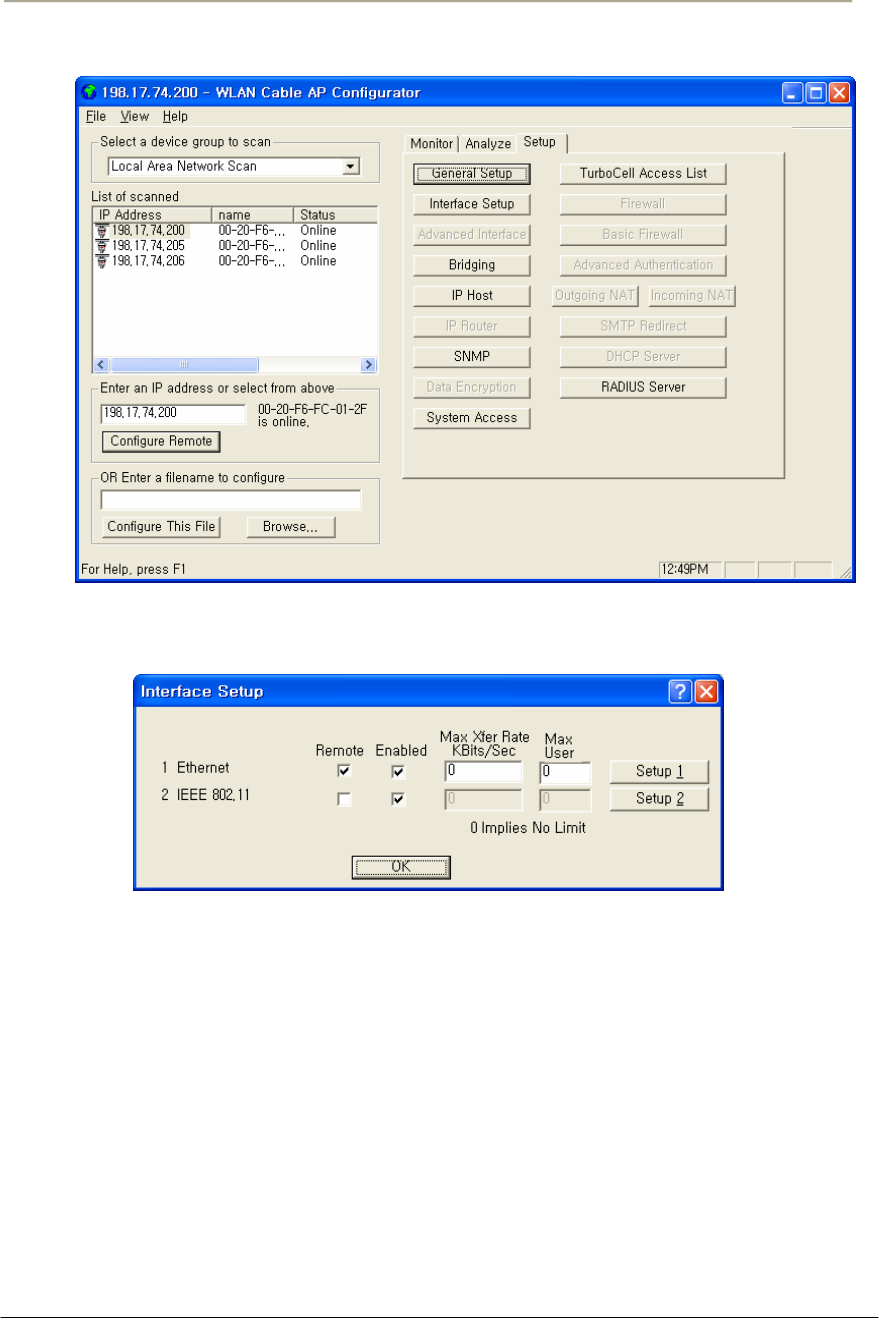
90
Access Point Unit: 2.4G-B-Radio-POE NTPM99AE 01 Rel 1.0 Issue1 May 2007
Figure 3-27 AP Configurator Main window
Figure 3-28 Interface setup dialog box
15. If you have an 802.11 radio card, click the Setup 2 button to set up
the 802.11 interface.
16. Click the Setup 2 button. The IEEE 802.11 Setup screen is
displayed, as shown in Figure 3-28.
17. Select a radio standard to use according to the built-in antenna
specification like an operating frequency range.
Ex) 2.4GHz antenna : 802.11b/g, 5.8GHz antenna: 802.11a
18. Select the Enable Signal Quality Front Panel Display checkbox if
your unit has a front panel display that is capable of displaying the
signal quality.
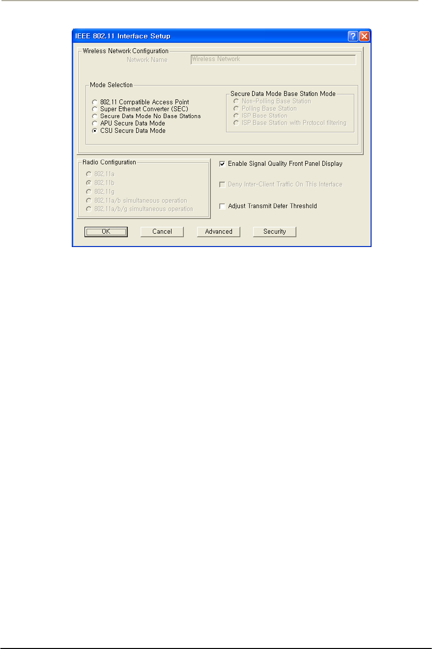
91
Access Point Unit: 2.4G-B-Radio-POE NTPM99AE 01 Rel 1.0 Issue1 May 2007
Figure 3-29 Interface setup dialog box
19. Click on the advanced button to set up crucial parameters such as
Radio Frequency, Transmit Rate (Bandwidth) and Network ID.
20. The Advanced Setup screen for a Secure Data Mode is shown
below.
21. Setup all radio parameters including a frequency channel and
transmit power referring to the permitted setting value specified in
the following tables per radio standard.
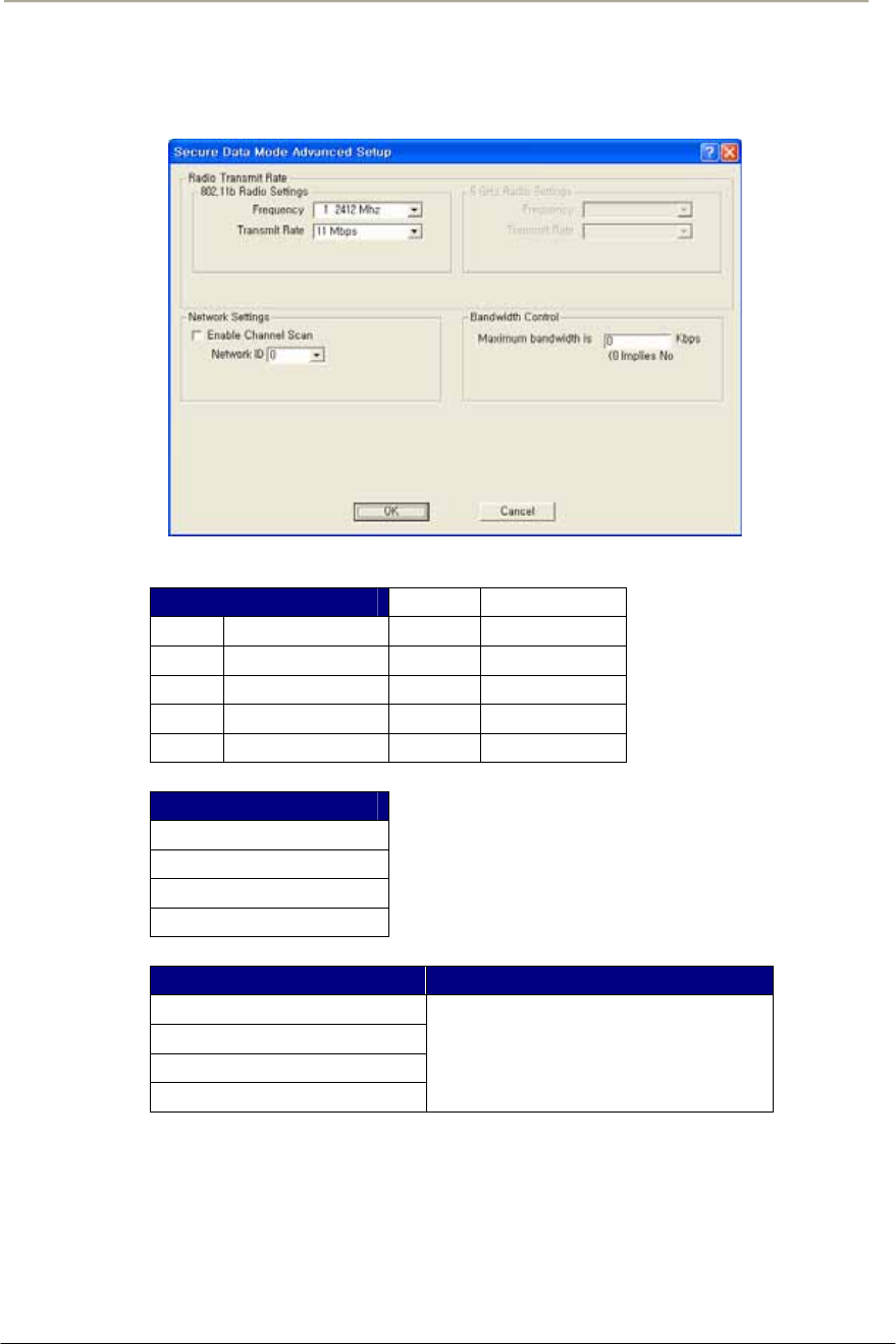
92
Access Point Unit: 2.4G-B-Radio-POE NTPM99AE 01 Rel 1.0 Issue1 May 2007
Figure 3-30 Advanced setup dialog box
[802.11b]
Frequency Channel 6 2437 MHz
1 2412 MHz 7 2442 MHz
2 2417 MHz 8 2447 MHz
3 2422 MHz 9 2452 MHz
4 2427 MHz 10 2457 MHz
5 2432 MHz 11 2462 MHz
Transmit Rate
11 Mbps
5.5 Mbps
2 Mbps
1 Mbps
Transmit Power Antenna Gain
Maximum
50%
25%
12.5%
Maximum allowable antenna
Gain(CSU/11B): 12dBi
Caution:Do not use any other antennas exceeding the allowed
maximum antenna gain value (12dBi) except as the built-in type of
antenna (ET-PR12) designated in Appendix B (Antenna) in case you
select 802.11b/g mode as operation radio standard.

93
Access Point Unit: 2.4G-B-Radio-POE NTPM99AE 01 Rel 1.0 Issue1 May 2007
Note: It is recommended that you set the transmit power to “Maximum”
as the antenna (ET-PR12) have been designed to meet FCC regulation
specifying the maximum allowable EIRP at the maximum transmit
power.
22. Select the Network ID in Network Settings referring to Figure 3-
23 “Wireless Network Planning.”
Note: the Secure Data Mode network ID number (0-15) is used to
differentiate between multiple Secure Data Mode stations using the same
System Access Pass Phrase. This is used to allow a Secure Data Mode
CSU to specify the APU mode unit that it wants to connect to if two
APU mode units can be seen by the same CSU. Generally, this value
should be the same as the Channel Number.
Note: The channel/frequency values are usually determined by network
administrators. If you set the channel and frequency in 802.11b/g, ensure
that there are at least four numerical channel differences between two
overlapping cells to avoid interference. For example, channels 1, 6 and
11 don’t overlap, but channels 1 and 3 do.
In the other side, if you are intended to use 802.11a, please keep in mind
that all channels (4 channels) with 20MHz bandwidth are not permitted
to be overlapped with each channels in the frequency plan.
23. Click “OK” button.
24. Click the Setup Æ IP Setup button. The IP Setup screen is
displayed, as shown below.
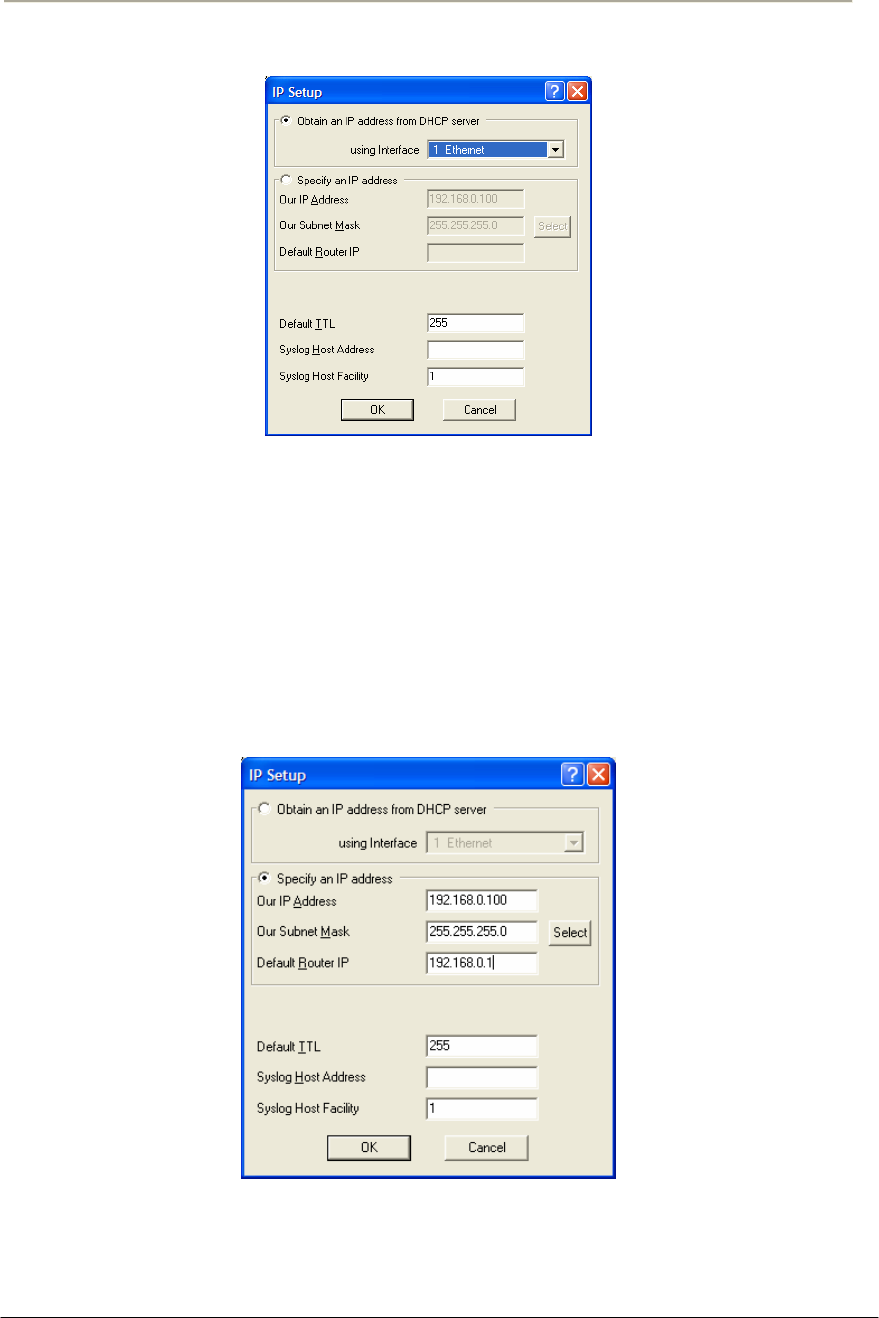
94
Access Point Unit: 2.4G-B-Radio-POE NTPM99AE 01 Rel 1.0 Issue1 May 2007
Figure 3-31 IP setup dialog box
Note: The IP Setup screen allows you to set the Secure Data Mode
Station's IP Addressing information. The Secure Data Mode Station must
have an IP address assigned to it if you wish to connect to it using the
Configurator tool, which makes use of SNMP to connect to the Secure
Data Mode Station.
25. Select “Specify an IP address” and type a specific IP address and
gateway IP address. Click OK button.
Figure 3-32 IP setup dialog box
Note: Except for cable modem built-in APU, the CSU to operate as CSU
mode is required to set a mandatory static IP address for the unit even
though it can be set in both static IP and DHCP setup.
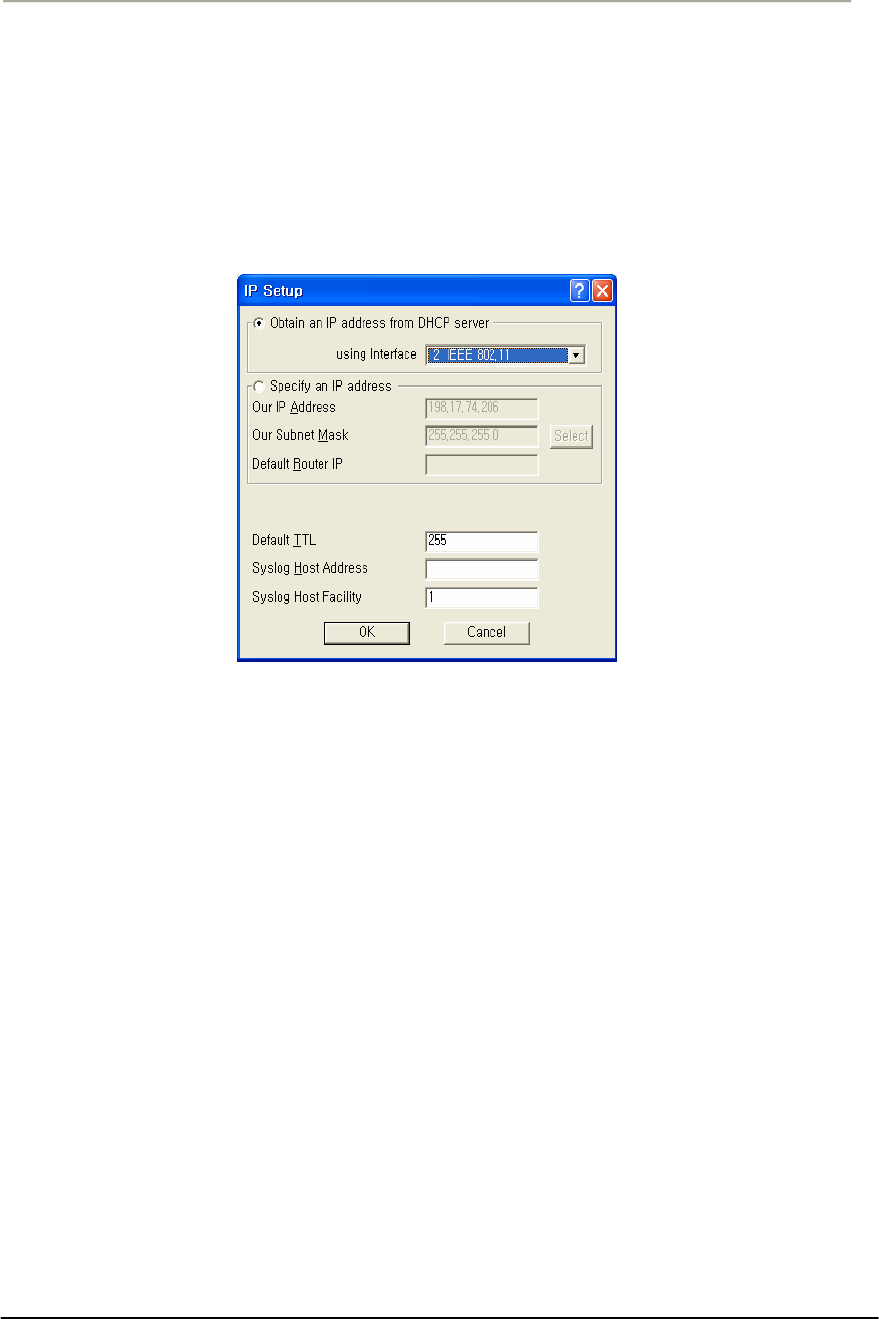
95
Access Point Unit: 2.4G-B-Radio-POE NTPM99AE 01 Rel 1.0 Issue1 May 2007
For your reference, APU and CSU (APU mode) have DHCP Server
feature which can assign an IP address to all networks entities like CSU
and PC in the sub-network.
Note: For DHCP client mode, select “2 IEEE 802.11” as the interface
which is used to get DHCP IP address from DHCP Server.
Figure 3-33 IP setup dialog box
Note: If you select the DHCP option, it is recommended (though not
required) that you set up your DHCP server to always provide the same
IP address to this Secure Data Mode Station system.
26. For a more detailed setup, refer to the procedure 3-5(Basic
Configuration) and 3-6(Advanced and Optional Configuration).

96
Access Point Unit: 2.4G-B-Radio-POE NTPM99AE 01 Rel 1.0 Issue1 May 2007
Procedure 3-4
Testing the connection between APU & CSU (APU mode) and CSU
The Configurators Wireless Link Test screen is used to diagnose the
wireless link quality between your APU and any CSU associated with
the APU.
The Wireless Link Test displays the diagnostic counters that apply to the
radio interface and a single remote station connected to this APU.
To assess the overall wireless performance in the wireless area served by
the APU, you might need to run Remote Link Tests with multiple CSUs
(one by one).
Action
Step Action
1. Prepare a Laptop computer and configure the test network as
shown in Figure 3-37. Prepare a CSU module, POE Injector and
Power supply system like a Power booster in a vehicle or regular
power outlet in the home.
Note: Ensure that the CSU and the Laptop computer are set to DHCP
Client so that they can get the IP address dynamically through the APU
from the Server.
2. The CSU has the same system parameters as the CSU (APU mode).
Set the system parameter as follows to test connection.
Table 3-4 System Main Parameters
Parameter APU CSU
IP address DHCP Client DHCP Client
Read Write Password User-specific User-specific
SNMP Secure
Configuration Password
User-specific User-specific
Mode Selection APU Secure Data Mode CSU Secure Data Mode
Base Station Mode Polling(Primary) N/A
Frequency User-specific User-specific
Transmit Rate User-specific User-specific
Network ID User-specific User-specific
Others User-specific User-specific
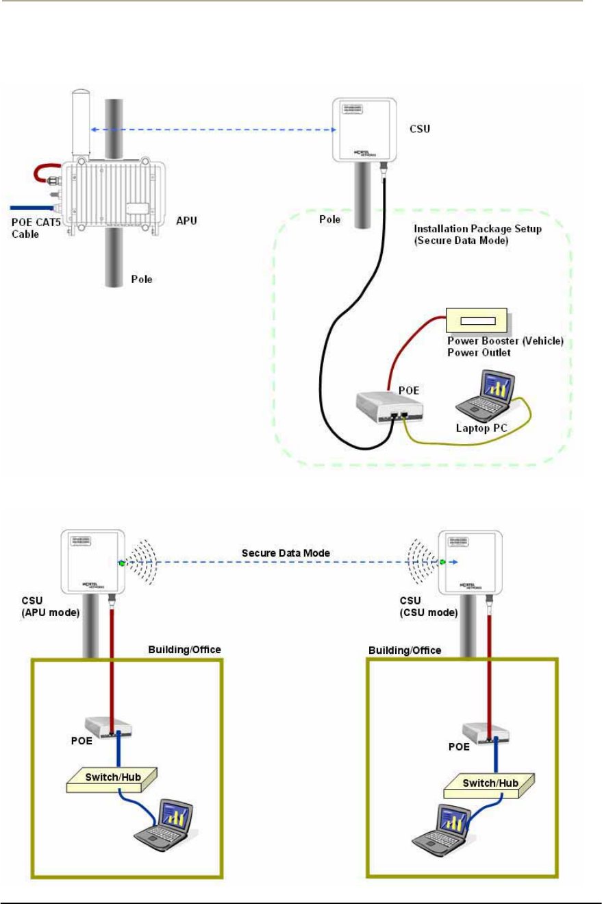
97
Access Point Unit: 2.4G-B-Radio-POE NTPM99AE 01 Rel 1.0 Issue1 May 2007
Figure 3-34 Test Network Configuration (Radio Connection)
[Case I] APU to CSU (PTP or PMP)
[Case II] CSU to CSU (PTP or PMP)
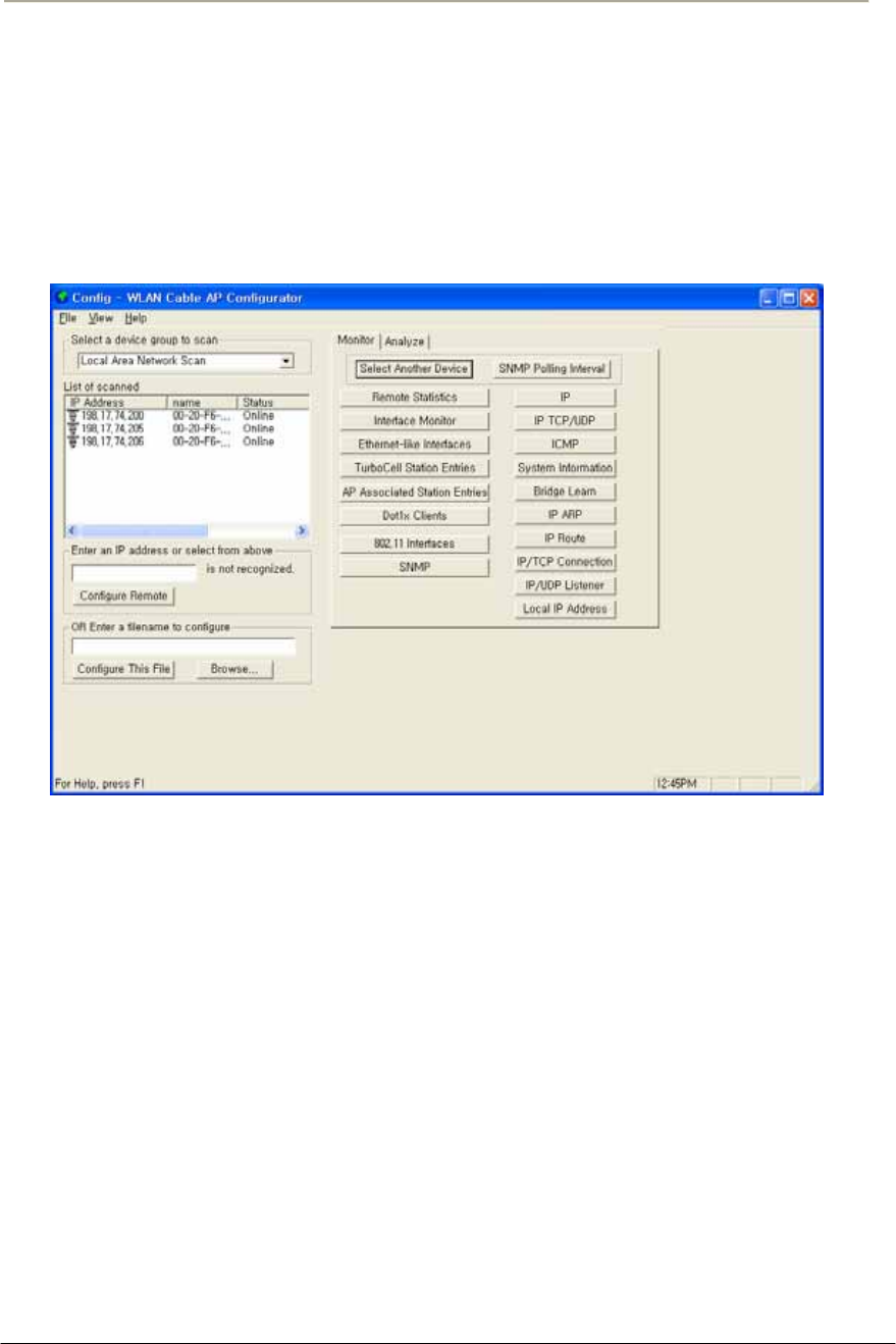
98
Access Point Unit: 2.4G-B-Radio-POE NTPM99AE 01 Rel 1.0 Issue1 May 2007
3. Launch the Configurator by either double clicking the WLAN
Cable AP Configurator icon on your desktop or by opening the file
config.exe from the directory “C:\Program Files\Nortel\WLAN
Cable AP Configurator” where software is installed.
4. The Configurator runs the IP Address for your APU and the Test
CSU (and the IP addresses for any other devices in your network)
appears in the Configurator window, as shown below.
Figure 3-35 Configurator Starting Window
5. Ensure that the laptop computer gets an IP address assigned from
the DHCP server at Network Center or statically defined by
checking an IP address list box at the left side of the configurator
window.
6. Check if all units of APU/CSU (APU mode) and Test CSU have
its own IP addresses.
7. If the APU/CSU (APU mode) you wish to configure is on the
same network subnet as your computer, you can select it from the
list that is automatically displayed in the IP Address window. Press
the <F5> key to refresh the scan list. Alternately, you can also
right click anywhere in the scan window and select Re-scan the
local network.
Note: To differentiate the APU/CSU (APU mode) to be configured, you
should check the AP MAC address of the APU/CSU (APU mode) which
is printed on the label attached to the side of the APU/CSU (APU mode).
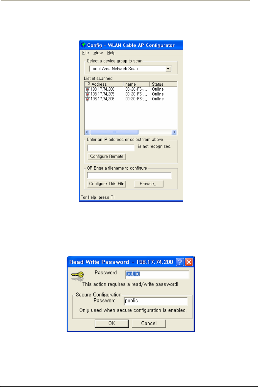
99
Access Point Unit: 2.4G-B-Radio-POE NTPM99AE 01 Rel 1.0 Issue1 May 2007
8. If you can find out the IP address of the APU on the IP address
window, move the cursor to the appropriate IP address.
Figure 3-36 IP address list box
9. Right click on the IP address, and click the Configure button
below the list box on the left side of a configurator window. The
Read/Write Password screen is displayed, as shown below.
Figure 3-37 SNMP Password (Read/Write)
10. Enter the password “public” for the device you have selected at
both text boxes, and then click the OK button.
11. If the Setup tab is displayed in the main window as shown below,
SNMP checking is a success.
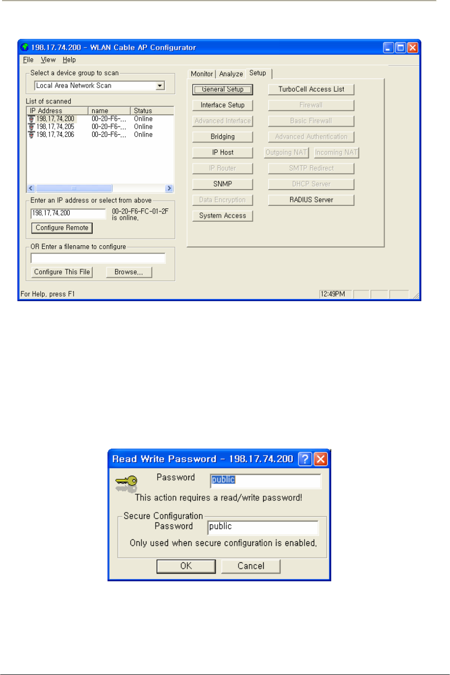
100
Access Point Unit: 2.4G-B-Radio-POE NTPM99AE 01 Rel 1.0 Issue1 May 2007
Figure 3-38 Setup Tab
Note: When you test the APU/CSU (APU mode) with Test CSU, you
don’t have to change the parameters of APU/CSU (APU mode) with AP
configurator. After all the tests are completed, you should configure the
APU/CSU (APU mode) according to your local network design concept.
12. Select Wireless Link Test from the Analyze Tab. The Enter IP
Address screen is displayed, as shown below.
Figure 3-39 SNMP Password (Read/Write)
13. Enter the Remote IP Address and Read/Write password for the
wireless station you wish to test. The Select a Remote Link
Partner screen is displayed, as shown below.
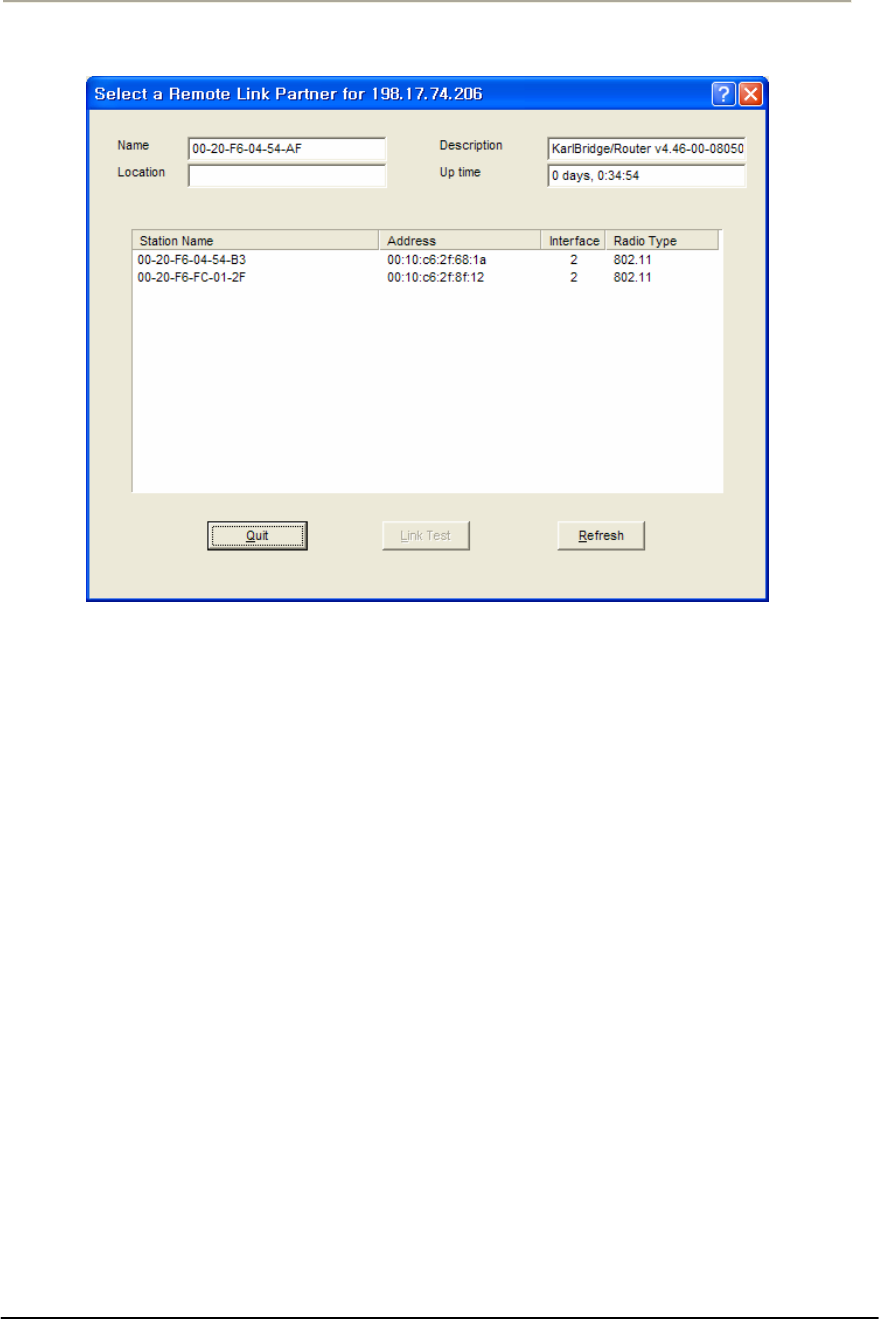
101
Access Point Unit: 2.4G-B-Radio-POE NTPM99AE 01 Rel 1.0 Issue1 May 2007
Figure 3-40 Remote Link List window
14. From the list of station names, select the remote station or client
you wish to test. Select a station from the list, and then click on the
Link Test button to perform a link test.
Note: Clicking the Explore button refreshes the list of stations that
can be selected.
15. Click the Link Test button to start the link test.
Note: When you open this screen, the base station will need
approximately 20 seconds to build the list of stations and forward
this information to your configurator station. Due to the dynamic
characteristics of mobile wireless stations, the base station will
rebuild the list of connected stations each time you select a
different station, or after clicking the Explore button. If this screen
does not display any station, there might be no wireless station up
and running in the vicinity of the selected base station.
16. The Remote Link Test screen displays the results of your wireless
link test, as shown below.
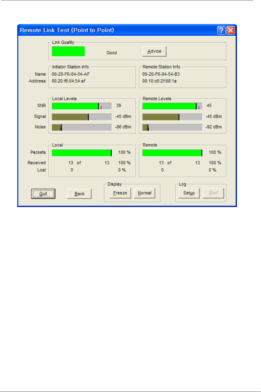
102
Access Point Unit: 2.4G-B-Radio-POE NTPM99AE 01 Rel 1.0 Issue1 May 2007
Figure 3-41 Remote Link Test Status Window
17. The advice button enables you to investigate the outcome of the
Remote Link Test assessment in more detail and provides you with
troubleshooting hints to improve the quality of the link between
the two remote nodes. The following table summarizes the
possible results of clicking the Advice button, and what action is
warranted based on the results:
18. It is necessary that you adjust the vertical tilt and horizontal angle
toward APU at the mounting point of CSU, while monitoring the
RF link quality status window so that the SNR and Link status bar
for the best quality.

103
Access Point Unit: 2.4G-B-Radio-POE NTPM99AE 01 Rel 1.0 Issue1 May 2007
Table 3-5 Radio Link Status
Status Risk Action
Excellent None You do not need to perform further
diagnostics.
Good None You may try to optimize antenna
placement to see whether this will
improve the Link Quality result.
Marginal Communication is still
possible, but this
situation may affect the
unit's performance.
View Link Test Details to verify.
The unit may have to retransmit lost
packets.
Verify the Signal Level indicator. A
low Signal Level indicates the unit
has moved away from the base
station.
View Link Test Details to verify the
Noise Level indicator. A high Noise
Level indicates a source of
interference in the signal path
between the unit and the base
station.
Select another unit to verify if the
base station is functioning properly.
Try to optimize antenna placement
to improve the Signal Level or move
it away from the source of
interference.
“No
Connection”
Communication is no
longer possible. If the
unit was in the process
of transferring files, data
may not have arrived at
the intended destination,
or it may have been
corrupted.
View Link Test Details to verify the
Signal Level indicator. A low Signal
Level indicates the unit has moved
away from the base station.
View Link Test Details to verify the
Noise Level indicator. A high Noise
Level indicates a source of
interference in the signal path
between the unit and the base
station.
Select another unit to verify if the
base station is functioning properly.
Try to optimize antenna placement
to improve the Signal Level or move
it away from the source of
interference.

104
Access Point Unit: 2.4G-B-Radio-POE NTPM99AE 01 Rel 1.0 Issue1 May 2007
Quality
Indicator is
Black
None. The base station
may be busy collecting
diagnostic measurement
results from the unit.
If the indicator remains blank, click
the other button to return to the
Select a Remote Link Partner screen.
Click the Explore button to refresh
the list of Link Test Partners. If the
initial partner no longer appears, it
may have been switched off, or have
been moved outside the range of the
selected Initiator Station.
Select another Link Test Partner to
verify if the base station is
functioning properly.
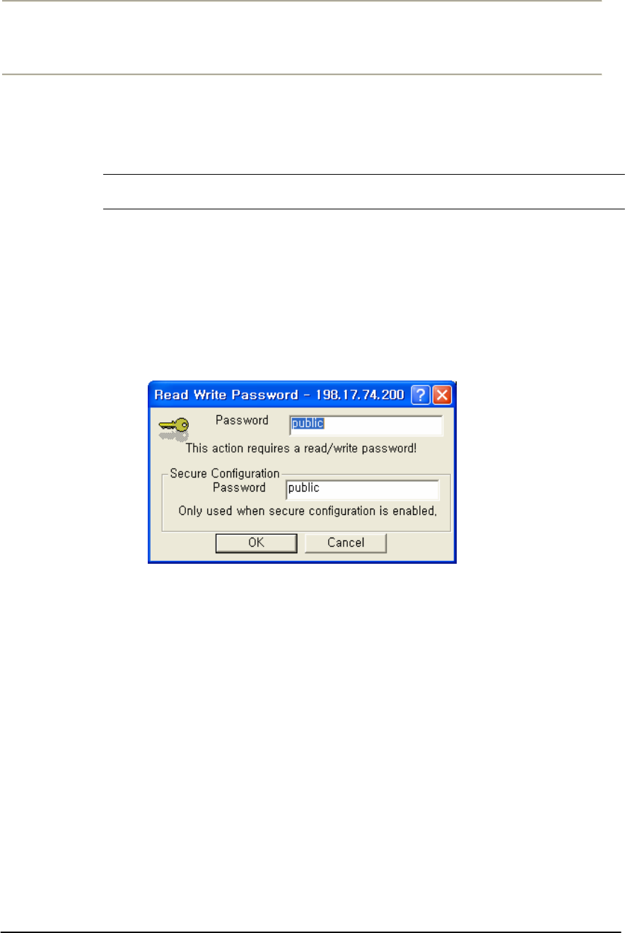
105
Access Point Unit: 2.4G-B-Radio-POE NTPM99AE 01 Rel 1.0 Issue1 May 2007
Procedure 3-5
Testing Wireless Network Performance
Testing Wireless Network Performance (Ping Fill Test)
Action
Step Action
1. On the Analyze tab, click the Ping Fill Test button. The Enter IP
Address screen is displayed.
Note: The above IP address should be that of the CSU (Client of APU)
which can get the IP address list box at the AP configurator.
Figure 3-42 IP Address Tab
2. Enter the IP address and Read/Write Password of the Internet host
with which you would like to test throughput, and click the OK
button. The Ping Fill Test Parameters screen is displayed. .
Note: To test wireless performance, the target system can be one of
the APU Secure Data Mode station's clients. You can also use a
wired host to test wired interface performance.
3. Enter the Test Window Size, Max Packets, and Test Running Time.
Ex) Packet Length: 60, Window size: 80, Maximum Packets: 20,
Number of Seconds: 5
4. Click the OK button. You will see some warning messages, and then
the Ping Fill test will run. The results of the test are then displayed in
the Ping Fill Results screen.
5. Choosing the correct parameters is crucial to obtain the accurate Ping
Fill Test results. To find out more about each of the parameters, click
in the fields shown in the screenshot below.
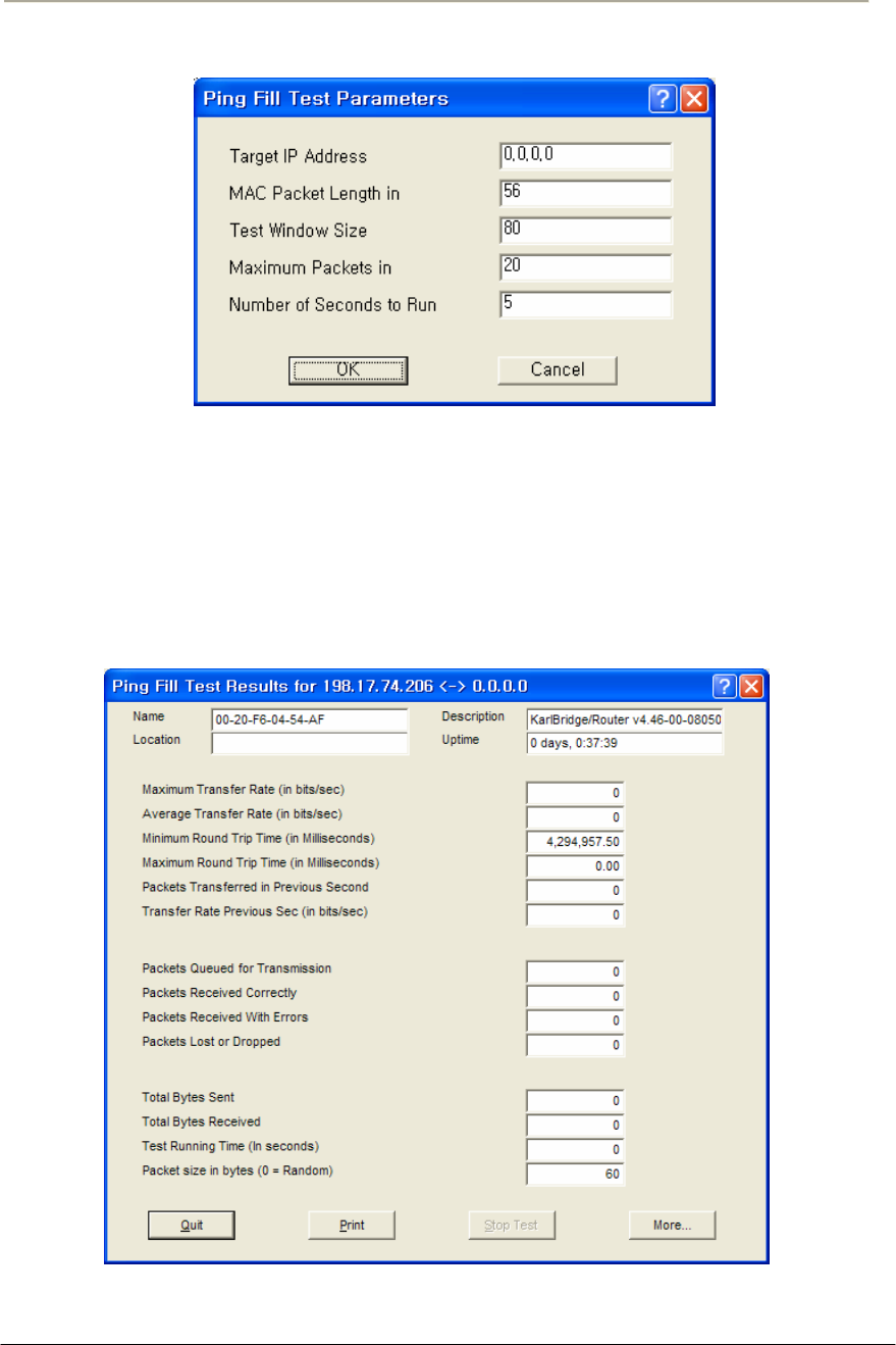
106
Access Point Unit: 2.4G-B-Radio-POE NTPM99AE 01 Rel 1.0 Issue1 May 2007
Figure 3-43 Ping Fill Test Parameters
6. As soon as Ping Fill test is over, you can see the result windows as
below.
7. Record the results of Average Transfer Rate. It is recommended
that the results window be captured as a picture and saved in the
file.
Figure 3-44 Ping Fill Test Results Window
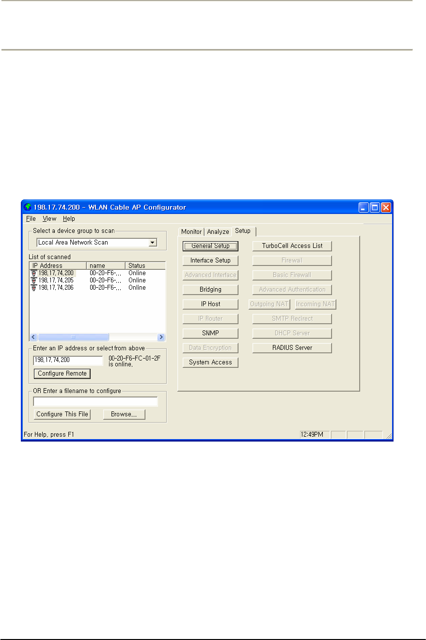
107
Access Point Unit: 2.4G-B-Radio-POE NTPM99AE 01 Rel 1.0 Issue1 May 2007
Procedure 3-6
Basic Configuration
Set Up General Configuration Options
The Setup tab is used to define the configuration options for the device,
and the General Setup screen is used to enable various setup options.
Click on the Setup tab, then click the General Setup button to display the
General Setup screen as shown below:
Figure 3-45 General Setup window
Note: This menu has been modified for use in this manual. This menu
has all the supported features checked (enabled) and is NOT typical of
the menu you will see. Each of the fields on the screen is explained
below.
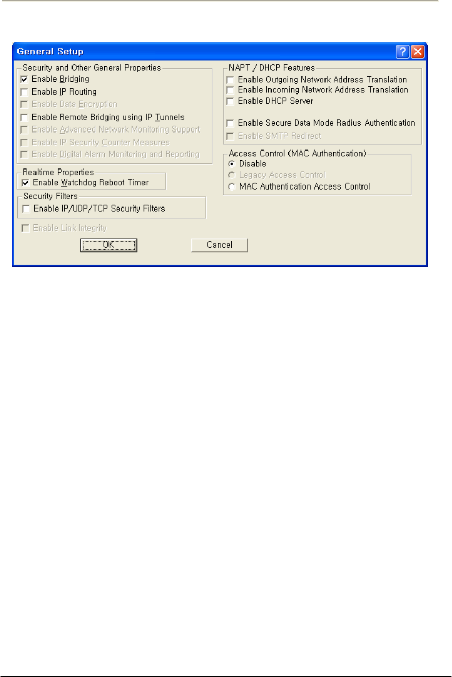
108
Access Point Unit: 2.4G-B-Radio-POE NTPM99AE 01 Rel 1.0 Issue1 May 2007
Figure 3-46 General Setup window
Enable Bridging
Selecting this checkbox in General Setup will allow you to access the
Bridge Setup screen, which you can use to enable your device’s
transparent Ethernet bridging feature. This allows for the transference of
Ethernet packets between physical networks connected directly to the
base station.
If enabled, the base station will transfer Ethernet packets from one
interface to the other (for example, between the wireless and the wired
networks). The default behavior is to bridge all Ethernet protocols. You
can set which Ethernet protocols to bridge or deny, as well as, Ethernet
stations that will be allowed or disallowed to send packets over the
bridge using Bridge Setup from the Setup tab.
If disabled, only the IP packets with correct the IP Routes set up in the IP
Router Setup will be bridged between the base station's various
interfaces; general Ethernet packets will not be transferred across the
base station. This would be useful in a situation where you want to
enable IP traffic, but not general Ethernet traffic between (sub) networks.
Enable IP Routing
Selecting this checkbox in General Setup will enable your hardware
device to route IP packets between its various interfaces.

109
Access Point Unit: 2.4G-B-Radio-POE NTPM99AE 01 Rel 1.0 Issue1 May 2007
If enabled, you will need to set up routes on the IP Routing screen or you
will not be able to access your hardware unit when you exit the
Configurator program.
Enable Remote Bridging Using IP Tunnels
This option allows you to encapsulate Ethernet packets of any protocol in
IP and then send them to another Secure Data Mode Bridge/Router to de-
encapsulation. Select this checkbox to enable this capability.
Some versions of the Secure Data Mode Station support a special feature
which will enable Ethernet packets of any protocol type to be
encapsulated in IP and then sent to other Secure Data Mode Stations for
de-encapsulation. This method can be used to set up "virtual" Ethernet
LANs between several points using the IP network as the transport layer.
This feature can be used to create a Virtual Private Network when used
in conjunction with the Data Encryption option.
Enable Watchdog Reboot Timer
Select this item in General Setup to enable the watchdog timer reboot
feature. If packets are not seen on the network for more than 10 minutes,
(a very rare occurrence) the Secure Data Mode Station will reboot itself.
Once it has rebooted, the 10 minute reboot timer will not activate again
until a packet has been seen on one of the interfaces. This is to ensure
that only one reboot will occur if the entire network is truly shut down.
Enable IP UDP/TCP Security Filters
Select this option in General Setup to enable the base station's Firewall
(IP Security Filter) features. You can set the base station to explicitly or
implicitly allow or deny IP connections to specific UDP or TCP ports,
and/or between specific IP addresses or subnets. For more information,
see Firewall Setup.
Note: This option is only available when the MAC Authentication
Access Control button has been selected on the General Setup screen.
Enable Outgoing Network Address Translation
Select this checkbox if you will be using Outgoing NAT to multiplex
traffic from all the computers on your internet network through the
Secure Data Mode Bridge/Router.
Outgoing Network Address Translation (NAT) allows multiple
computers to share a single IP address to connect to an IP network,
including the Internet. This allows homes, small businesses, and Internet
Service Providers to have Internet service for all of their computers
without having to pay for additional IP addresses. The NAT feature

110
Access Point Unit: 2.4G-B-Radio-POE NTPM99AE 01 Rel 1.0 Issue1 May 2007
serves as a simple firewall for incoming connections, since only traffic
initiated by an interior computer is permitted through the NAT.
Enable Incoming Network Address Translation
Select this checkbox if you will be using Incoming NAT to multiplex
traffic from the network to all the computers on the internal network.
Incoming Network Address Translations (NAT) is used to redirect
requests to servers in the local address space based on the port of the
request. If, for example, the client at local address 10.0.1.2 is serving
web pages, and a request comes to the access point on that port for a web
session, then the request will be forwarded to the web server on 10.0.1.2.
The server will respond with the web page to the address of the original
request.
Note: Incoming NAT only needs to be configured if servers in the local
(private) Address space needs to connect with clients in the global
(public) address space.
Enable DHCP Server
Select this checkbox if you are using the Secure Data Mode Bridge/
Router to provide DHCP information to the computers on your network.
Note: If you do not check this option, you will not be able to access the
DHCP Server screen.
Enable Secure Data Mode Radius Authentication
Select this checkbox if you wish to enable RADIUS authentication for
your Secure Data Mode stations.
Enable Network Address Translation Redirector
Select this checkbox if you wish to enable network address translation
(NAT) redirection, which is used to forward the packets sent to a
particular port number to a specified IP address, regardless of the original
destination IP address.
Access Control Buttons
The access control buttons determine how authentication is controlled.
There are three possible means of authentication control:
Disable - Selecting Disable turns off MAC authentication entirely.
Legacy Access Control - Selecting Legacy Access Control enables
access to the Access Control Setup screen and disables access to the
Advanced Authentication screen
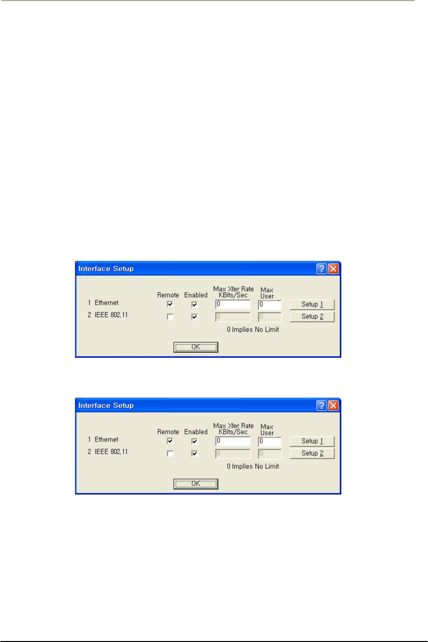
111
Access Point Unit: 2.4G-B-Radio-POE NTPM99AE 01 Rel 1.0 Issue1 May 2007
MAC Authentication Access Control - Selecting MAC
Authentication Access Control enables access to the Advanced
Authentication Setup screen, which provides more detailed MAC
authentication setup options, and disables access to the Access
Control Setup screen.
Set Up Interfaces
Once you have enabled various configuration options, you need to define
the network interfaces for your hardware device. You will typically set
up one or more of the following interfaces:
As the name suggests, the Interface Setup screen is used to set up
network interfaces. From the Setup tab, click the Interface Setup button.
The Interface Setup screen is displayed, as shown below:
Figure 3-47 Interface setup window
Interface (APU)
Interface (CSU)
The following rules apply for setting up network interfaces:
You do not need to set up the Ethernet Interface.
If you have an 802.11 radio card, click the Setup 2 button to set up
the 802.11 interface.
Remote Checkbox -- Select this checkbox if all traffic coming in on this
interface is to be viewed as remote traffic for firewall, bridging, filtering,
and routing purposes. If this checkbox is not selected, then all traffic on

112
Access Point Unit: 2.4G-B-Radio-POE NTPM99AE 01 Rel 1.0 Issue1 May 2007
this interface will be considered local traffic. Note that the “Remote”
designation is significant only for the Security filters, and does not imply
physical location. The security filters will pass (permit) or drop (deny)
packets of particular types from being forwarded between interfaces
designated as “Local” (unchecked) and those designated as “Remote.”
Note: At least one enabled interface must be a remote interface.
Enabled -- Select this checkbox if this interface should be enabled. If
this box is not selected, then the base station will disable the interface
and it will not be used, and the interface itself will be "down" from an
administrative standpoint.
Note: At least one enabled interface must be a remote interface.
Maximum Transfer Rate (Kbits/sec) -- The maximum transfer rate is
the number of bits that can be used for sending and receiving packets. If
you wish to limit the maximum data transfer rate for a particular
interface, enter the maximum number of kilobits per second that can be
transmitted from and to the base station. This helps to reduce the risk of
over-powering remote sites and to limit the bandwidth used by a
particular base station.
Note: The transfer rate represents the total transfer rate for both sending
and receiving packets. For example, if you set the transfer rate to 10,000
Kbits (10 Mbits) per second, then 10 Mbits represents the maximum rate
available for both sending and receiving packets. Therefore, if you use 7
Mbits per second in sending the packets, then only 3 Mbits per second
are available for receiving packets.
Setup 1, 2, 3 -- The Setup 1, 2 buttons are used to define the available
interfaces. In the screenshot shown above, clicking Setup 1 will display
the Ethernet Setup screen, clicking Setup 2 will display the 802.11 Setup
screen. Each of the Interface Setup screens is explained in more detail
below.
Set up Ethernet
Clicking the Setup 1 button on the Interface Setup screen displays the
Ethernet Setup screen.
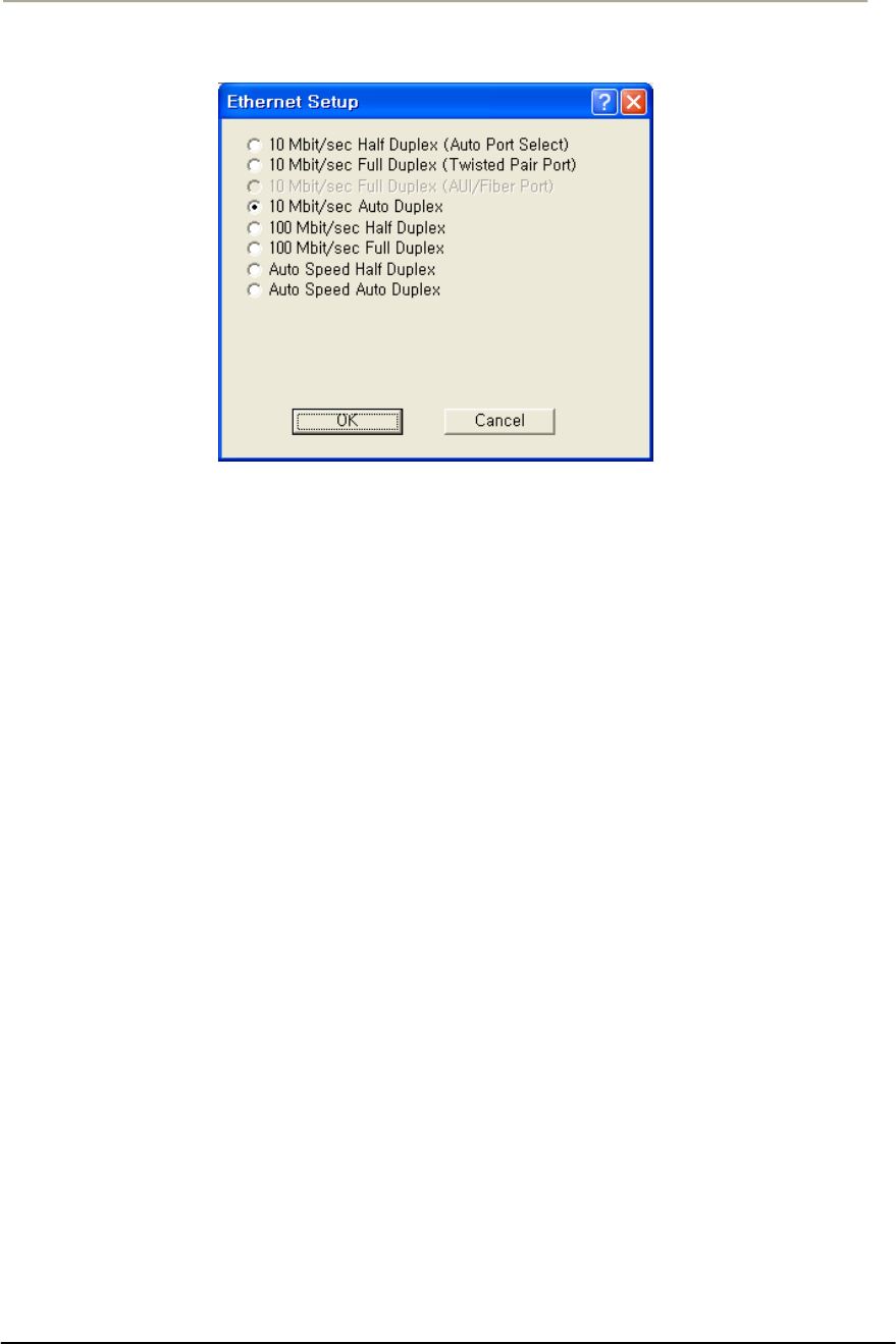
113
Access Point Unit: 2.4G-B-Radio-POE NTPM99AE 01 Rel 1.0 Issue1 May 2007
Figure 3-48 Ethernet Setup window
The Secure Data Mode station will automatically set up the Ethernet
interface to use the type of medium that has been connected to the unit.
By default, the Ethernet connection is set at “Auto speed auto duplex.”
Therefore, you do not need to configure special settings for the Ethernet
hardware interface. If you wish to customize the Ethernet settings, you
can change the settings listed below. However, you do not need to
change any settings for your hardware device to be functional.
The Secure Data Mode Station supports both Ethernet IEEE 802.3
and DIX Ethernet frame types.
Protocols are set in the Interface Setup window of the Setup Tab.
Note: Do not change the default setup “Auto speed Auto Duplex” in this
setup window without consulting the manufacturer.
Ethernet Type -- The Ethernet type options provide a variety of
Ethernet settings. The default value for Ethernet type will vary,
depending on your hardware device. Only the settings that are enabled
on your screen are supported by your particular hardware device. If your
switch or Ethernet card supports different speeds, you may want to
change the speed setting.
Set Up 802.11
Clicking the Setup 2 button on the Interface Setup screen displays the
802.11 Setup screen. The 802.11 Setup screen is used to set up the
interface to your 802.11 network devices.
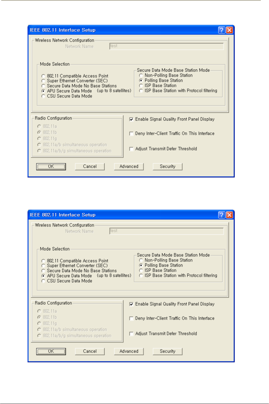
114
Access Point Unit: 2.4G-B-Radio-POE NTPM99AE 01 Rel 1.0 Issue1 May 2007
Figure 3-49 802.11 Radio Interface Setup window (APU Secure Data Mode)
Figure 3-50 802.11 Radio Interface Setup window (CSU Secure Data Mode)
802.11 Network Name-- The 802.11 Network Name is used in standard
IEEE 802.11 networks to distinguish stations in your 802.11 network
from stations that belong to a neighboring 802.11 network.

115
Access Point Unit: 2.4G-B-Radio-POE NTPM99AE 01 Rel 1.0 Issue1 May 2007
The value used for the radio interface on this station should be the same
for all wireless stations in the 802.11 network. Only stations configured
with the proper 802.11 Network Name will be able to connect to the
802.11 station's radio interface.
The Network Name can be any alphanumeric string in the range of "a" to
"z,” "A" to "Z" and "0" to "9,” and can contain from 1 to 32 characters.
If you wish to allow access to the wireless network to be open to all
wireless stations, the Network Name should be set to ANY.
Note: The Network Name is used only when the 802.11 radio interface
(for example, Orinoco) is set to run in IEEE 802.11ccess Point Mode.
Secure Data Mode No Base Stations-- Select this option to set your
802.11 device's radio card on this interface to run as a Secure Data Mode
Network without a Secure Data Mode Base Station (i.e. peer-to-peer).
Use this setting only in the rare instance when all Secure Data Mode
stations are able to "see" each other (i.e., there are no hidden nodes).
When all connected Secure Data Mode Stations are not able to "'see" one
another, this setting should not be used. In that case, you should set one
of your Secure Data Mode Station stations to Secure Data Mode Base
Station, and the others to Remote (Satellite) Secure Data Mode Stations.
APU Secure Data Mode-- Selecting this option sets the Secure Data
Mode Station to run as a Secure Data Mode Base Station over the 802.11
device's radio interface. Every system that needs to connect to the
wireless network must be able to connect to the Secure Data Mode Base
Station.
When you select this Base Station type, you must select one of the
Protocol Filtering Modes. The Protocol Filtering Mode determines how
the base will interact with the satellite (slave) stations. Is it recommended
that you use the Enable Filters between Slaves mode.
The possible base station modes are as follows:
Non-Polling Base Station
The non-polling Secure Data Mode Base Station Mode is provided
mostly for compatibility with older Secure Data Mode Networks, but
may give increased performance over other (polling) Secure Data Mode
Base Station modes in a lightly loaded network, or in a network with
only a few satellites.

116
Access Point Unit: 2.4G-B-Radio-POE NTPM99AE 01 Rel 1.0 Issue1 May 2007
Setting a base station to non-polling mode may increase performance in
the rare case where all satellites can hear one another (i.e. there are no
hidden nodes), or when there is sporadic network use. In an environment
where most network traffic is with one satellite, and other satellites rarely
transmit data, this setting may also increase performance. However, it is
highly recommended that you select one of the polling modes.
Selecting this Secure Data Mode Base Station Mode takes full advantage
of the features of a Secure Data Mode Network.
Polling Base Station
Selecting this Secure Data Mode Base Station Mode sets the Secure Data
Mode Station to run as a Secure Data Mode Base Station which performs
a highly optimized polling of the satellite stations for data. In the Non-
Polling Base Station mode, all wireless stations must be able to 'hear'
each others' traffic, or performance may degrade considerably (the
hidden node problem). In polling mode, the Base Station will poll each
station for data, and also offer the opportunity for 'free-for-all' sending of
data at set intervals.
In conjunction with the standard features of the Secure Data Mode
Network, this Secure Data Mode Base Station Mode offers a significant
performance increase over other wireless protocols when the network is
under a heavy load.
ISP Base Station
Selecting this Secure Mode Base Station sets the Secure Mode Station to
run as a base station for connections to Microsoft Windows PC Clients.
This mode takes full advantage of the features of a Secure Mode
Network and allows Windows clients to connect directly to the base
station, eliminating the need for an Ethernet connection to a second
Secure Mode Station running as a Remote Secure Mode Station.
The following Windows clients are supported:
Windows 95a (with the Winsock 2 update)
Windows 95b
Windows 98
Windows NT 4.0
Windows XP
To filter Ethernet protocols that are transferred between the wireless
stations (for example, to disable the Windows Network Neighborhood),
select ISP Base Station with Protocol Filtering. Filters set in Bridge

117
Access Point Unit: 2.4G-B-Radio-POE NTPM99AE 01 Rel 1.0 Issue1 May 2007
Setup... are not applied to wireless-only traffic in the non-filtering ISP
Secure Data Mode Base Station Mode.
We strongly recommend that you set your Secure Data Mode Base
Station to ISP Base Station with Protocol Filtering mode when
connecting Windows PC Client satellites.
ISP Base Station with Protocol Filtering
Selecting this Secure Data Mode Base Station Mode gives you the same
functionality of the ISP Base Station mode, with an added filtering
function that applies the bridge filters set in Bridge Setup to traffic sent
over the wireless network as well.
With the non-filtering ISP Secure Data Mode Base Station Mode, all
traffic between two wireless stations is permitted. Bridge filters do not
apply to wireless-only traffic in the non-filtering ISP Secure Data Mode
Base Station Mode.
When using the ISP Base Station with the Protocol Filtering setting, you
can set the bridge filters so that each wireless machine (or LAN behind
another connected Secure Data Mode Station) is 'hidden' from all other
machines or LAN's connected to the Secure Data Mode Network.
Properly setting up Protocol Filtering will disable the Windows 'Network
Neighborhood' from seeing other machines connected on the wireless
network. If you do not deny IP and IP-ARP packet types in Protocol
Filtering, wireless machines are still able to connect to each other via IP
packets, including TCP and UDP. Permitting only IP traffic over the
wireless network will allow your wireless clients to interact as if they
were connected to the Internet, but not together on a private network. For
added security, the firewall features of the bridge can be used to deny
certain types of IP packets from flowing between the wireless stations.
We strongly recommend that you select ISP Base Station with Protocol
Filtering when the Secure Data Mode Base Station will service satellites
running the PC Client.
CSU Secure Data Mode-- Selecting this option in IEEE 802.11 sets the
Secure Data Mode Station to Connect to an APU Secure Data Mode
Station over this 802.11 device’s radio interface.
To properly use this setting, you must be sure that the following items
match the APU Secure Data Mode Station Settings:
Network ID(NWID)
System Access Pass phrase
Frequency Channel
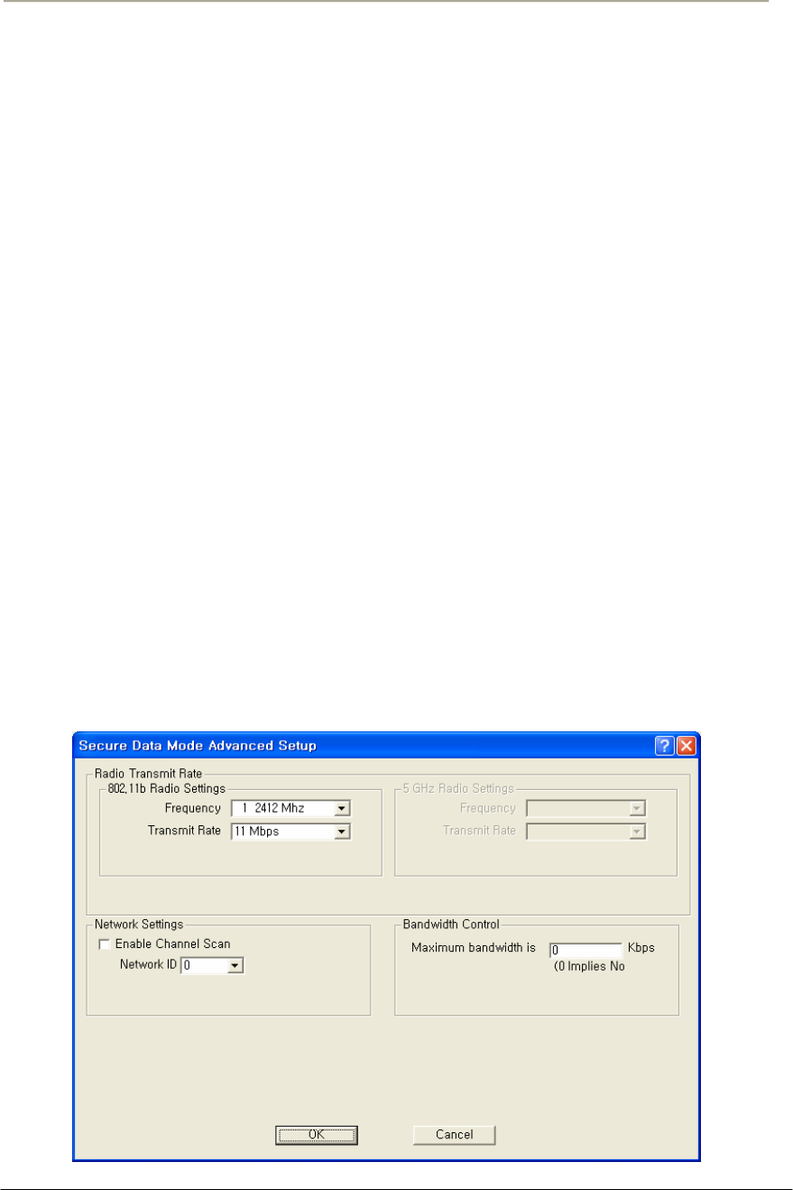
118
Access Point Unit: 2.4G-B-Radio-POE NTPM99AE 01 Rel 1.0 Issue1 May 2007
Enable Signal Quality Front Panel Display-- On units that have a front
panel display that is capable of displaying the signal quality, selecting
this checkbox will enable the signal quality display.
Deny Inter-Client Traffic on this Interface-- Select this checkbox if
you wish to prevent wireless stations from sending packets to each other
directly. Usually, the AP will repeat station-to-station traffic and will not
send it to the bridge and firewall filters. This is because bridging routines
historically work between physical interfaces only.
An Ethernet packet sent between two Ethernet hosts on the same
Ethernet subnet will automatically be seen by the destination host. With
wireless, the packet must be repeated by the AP. This turns off the AP’s
packet repeating code.
Secure Data Mode Advanced Setup
Clicking the Advanced Button on the 802.11 Setup screen displays the
802.11 advanced Setup screen, which allows you to configure more
options related to the setup of your 802.11 network device.
The appearance of the 802.11 Setup screen varies depending on which
options are set on the 802.11 Setup screen. The 802.11 Advanced Setup
screen for a Secure Data Mode Base Station is shown below.
Figure 3-51 Advanced setup dialog box
[802.11b]

119
Access Point Unit: 2.4G-B-Radio-POE NTPM99AE 01 Rel 1.0 Issue1 May 2007
Network ID-- Enter the Secure Data Mode network ID number (0-15)
used to differentiate between multiple Secure Data Mode stations using
the same System Access Pass Phrase. This is used to allow a Secure Data
Mode satellite to specify the Base Station it wants to connect to if two
base stations can be seen by the same satellite. Generally, this value
should be the same as the Channel Number.
802.11 Frequency Setup-- Click the Frequency button on the 802.11
Setup screen displays the 802.11 Frequency Setup screens, which allows
you to set the Frequency Channel for your 802.11 radio card.
The 802.11 Frequency Setup screen is used to change the channel and
frequency for one of the remote devices on your network. Note that this
screen is only accessible if you have identified remote devices in your
network. If all devices are in your local network, then the Frequency
Setup screen is unavailable.
Channel/Frequency-- Select the channel and frequency for the remote
device from the drop-down list. See Frequency Channels for a more
detailed explanation of the frequency channels.
[802.11b]
Frequency Channel 6 2437 MHz
1 2412 MHz 7 2442 MHz
2 2417 MHz 8 2447 MHz
3 2422 MHz 9 2452 MHz
4 2427 MHz 10 2457 MHz
5 2432 MHz 11 2462 MHz
Radio Transmit Rate-- Select the radio bit rate used to transmit.
Your choices are:
[802.11b]
Transmit Rate
11 Mbps
5.5 Mbps
2 Mbps
1 Mbps
A lower signal will increase the noise. In essence, the poorer the signal-
to-noise ratio, the lower this rate should be set.
Note: The transmit rate affects only the transmissions made by this
station.

120
Access Point Unit: 2.4G-B-Radio-POE NTPM99AE 01 Rel 1.0 Issue1 May 2007
Note: In case of 802.11b/g, the channel/frequency values are usually
determined by network administrators. If you set the channel and
frequency ensure that there are at least four numerical channels
difference between two overlapping cells to avoid interference. For
example, channels 1, 6 and 11 don’t overlap, but channels 1 and 3 do.
In the other side, if you are intended to use 802.11a, please keep in mind
that all channels (4 channels) with 20MHz bandwidth are not permitted
to be overlapped with each channels in the frequency plan.
Radio Transmit Power -- Select the Transmit power in the list of five
(4) power levels as below.
Transmit Power Antenna Gain
Maximum
50%
25%
12.5%
The allowed antenna gain per unit
varies with actual transmit power
of APU and CSU.
Note: It is recommended that you set the transmit power to “Maximum”
as the antenna listed in Appendix B (Antenna) has been designed to meet
FCC regulation to restrict the actual transmit power (EIRP) at the
maximum transmit power.
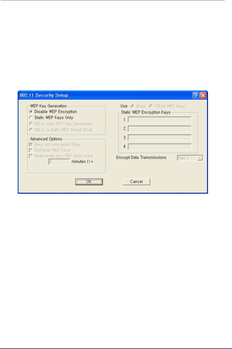
121
Access Point Unit: 2.4G-B-Radio-POE NTPM99AE 01 Rel 1.0 Issue1 May 2007
802.11 Security Setup
Clicking the Security button on the 802.11 Setup screen displays the
802.11 Security Setup screen, which allows you to set up security for
your 802.11 devices. Note that the fields shown in the screenshot below
will vary depending on the version of the Configurator you are using and
the options contained in the .bin file. The screen below shows all
available options.
Figure 3-52 802.11 Security Setup window
Disable WEP Encryption-- Select this button if you wish to disable
Wired Equivalent Privacy (WEP) encryption.
If you are not concerned about security (for example, home users using
this device only to browse the Internet), and if you are not concerned
your AP is used by others, then select this checkbox.
Note: For simple security, you can disable WEP encryption and select
the Closed Wireless System checkbox.
Static WEP Keys Only-- Select this button if you wish to enter Wired
Equivalent Privacy (WEP) keys identically on each access point/station
and Secure Data Mode unit in the network. When you select this button,
the four Static EP Encryption key fields are enabled on the right side of
the screen.

122
Access Point Unit: 2.4G-B-Radio-POE NTPM99AE 01 Rel 1.0 Issue1 May 2007
Deny Non-Encrypted Data-- Select this checkbox if you want to deny
all received data that is not encrypted. When this checkbox is selected,
any packet received that is not encrypted using one of the four WEP
Encryption keys listed above will be dropped. When this checkbox is not
selected, unencrypted packets will be accepted and/or forwarded.
Warning: You should always select this checkbox if WEP is enabled in
any form. If disabled, clients without WEP can access your network!
Use n-bit WEP Keys-- Select either 64-bit (silver) or 128-bit (gold)
encryption keys. The higher bit count provides somewhat higher security.
AES(Advanced Encryption Standard)—If you want more secured
encryption than n-bit WEP, you can choose this option with which 16
character string’s keys are supportable for Atheros based untis.
Static WEP Encryption Keys-- If you use static encryption keys, you
must enter each key in the Static WEP Encryption Keys fields. Note that
these keys must be entered identically on each access point/station and
Secure Data Mode unit in the network.
Encrypt Data Transmission Using Key n-- Enter the key number that
should be used to encrypt data on this interface. Note that you can
receive using any key, but will generally always transmit using a single
key. Unicast transmissions to an 802.1x station with dynamic keys will
use that’s station’s dynamic key, but all broadcasts, multicasts, and other
unicasts will be encrypted using the key identified in this field.
Configure the APU for Basic MAC Authentication
Advanced Authentication allows you to restrict access to an 802.11
access point by specifying the MAC Addresses of stations that can use
the wireless bridge
1. Select the Setup Tab, and then click the General Setup button. The
General Setup screen is displayed, as shown below.
2. Select the MAC Authentication Access Control radio button, as
shown in the screenshot, then click OK to close the General Setup
screen.
3. Click the Advanced Authentication button. The Advanced
Authentication Setup screen is displayed, as shown in Figure 3-54.
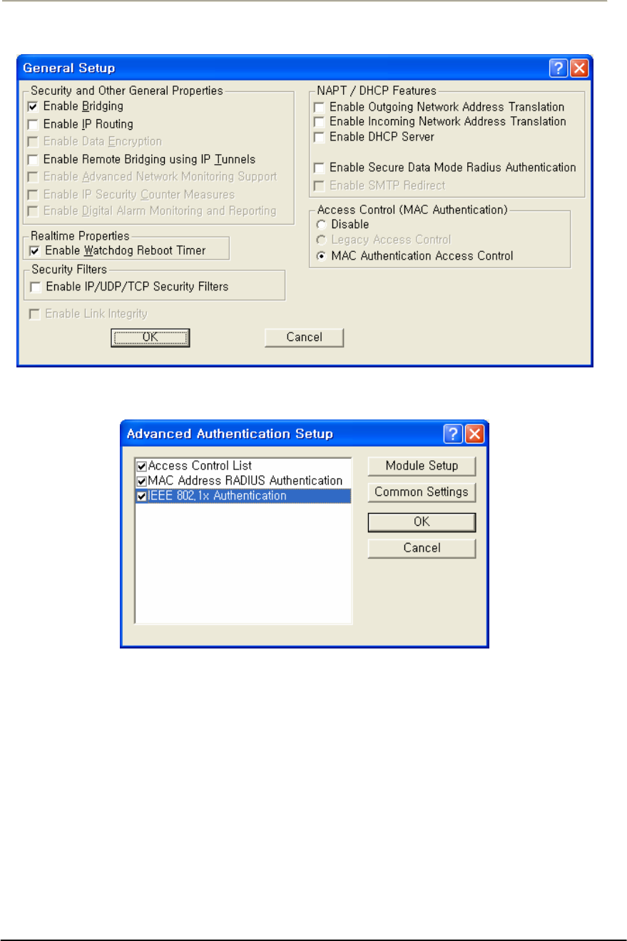
123
Access Point Unit: 2.4G-B-Radio-POE NTPM99AE 01 Rel 1.0 Issue1 May 2007
Figure 3-53 General Setup Window
Figure 3-54 Advanced Authentication Setup Window
When a station tries to connect to the hardware device (via Ethernet,
802.11, etc.), the AP can decide whether or not to forward packets to or
from that station based on authorization criteria. There are three
authentication modules that comprise MAC authentication, but the
network administrator determines which of those three modules are used.
xAccess Control List (ACL)
xMAC RADIUS Authentication (with optional WARP support)
These modules are enabled on a per-interface basis. This provides
greater control for the network administrator. In essence, the
administrator decides whether there will be more or less (or no)
authentication on an interface-by-interface basis.

124
Access Point Unit: 2.4G-B-Radio-POE NTPM99AE 01 Rel 1.0 Issue1 May 2007
For example, an administrator can permit MAC addresses entered as part
of the ACL only on 802.11, but can permit MAC addresses entered
through RADIUS Setup for both the Ethernet and 802.11 interfaces.
The modules are checked in the order in which they appear on the
Advanced Authentication Setup screen, and the options that have been
selected (checked) determine how authentication is carried out.
Assuming that all options are selected, the first method used is the
Access Control List, followed by MAC Address Radius, followed by
802.1x authentication. If no options are selected, then no authentication
takes place. Zero to three of the modules can be enabled, but at least one
module must be enabled for advanced authentication to take place.
The process by which authentication takes place is as follows:
The first module in the list (for example, ACL) checks the source
address of the incoming packet to see if it is permitted to send
packets on the selected interfaces.
The module will designate the address as one of the following:
xPermit -- the MAC address is permitted on this interface, and
packets are forwarded
xDeny - the MAC address is denied on this interface, and the
packets are not sent
xUnknown - the MAC address is not known on this interface, and
is passed to the next authentication module
If the designation is unknown, then it is passed to the next module in
the list (for example, from the ACL to MAC RADIUS
Authentication), and the process starts again.
Ensure that the MAC Address RADIUS Authentication checkbox is
enabled, and then click the Setup button. The Authentication Module
Setup screen is displayed as shown below.
Note: The number of tabs displayed on this screen will vary depending
on which Advanced Authentication options you have selected on the
Advanced Authentication Setup screen. In the screenshot below, all
Advanced Authentication options have been enabled.
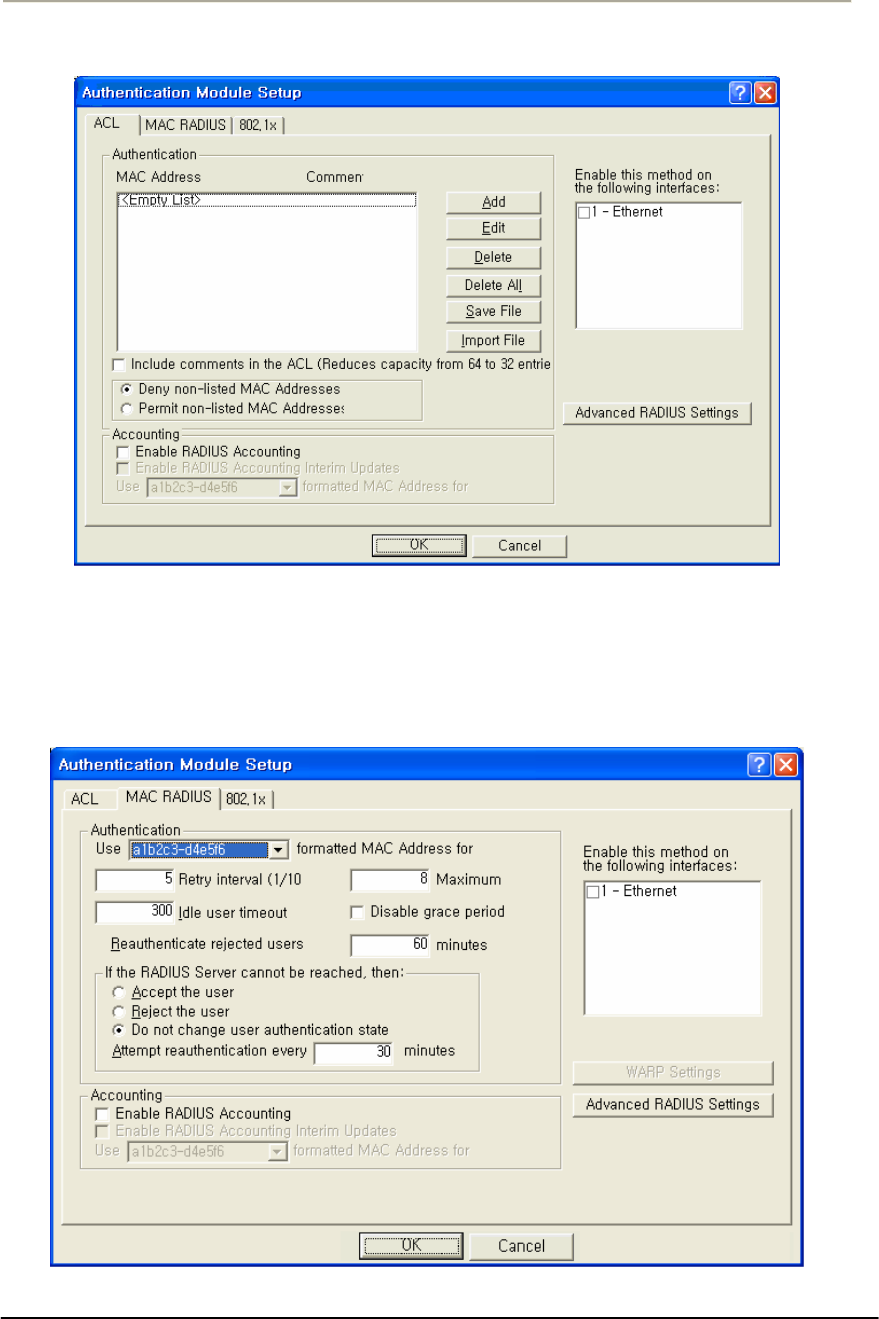
125
Access Point Unit: 2.4G-B-Radio-POE NTPM99AE 01 Rel 1.0 Issue1 May 2007
Figure 3-55 Authentication Module Setup Window
4. Click the MAC RADIUS tab. The MAC RADIUS Setup screen is
displayed, as shown below.
Figure 3-56 Authentication Module Setup Windows

126
Access Point Unit: 2.4G-B-Radio-POE NTPM99AE 01 Rel 1.0 Issue1 May 2007
The MAC RADIUS Setup screen is used to define advanced
authentication and accounting options for clients that are authenticated
via RADIUS using the client's MAC Address as the RADIUS username.
RADIUS authentication and accounting server IP addresses and port
numbers are set up using the MAC RADIUS Setup screen. Note that this
particular MAC RADIUS module applies only to Ethernet and 802.11
access point interfaces.
This screen is used in conjunction with the RADIUS Server Setup screen
to define various authentication options. If you wish to use accounting,
you must first set up accounting parameters on the RADIUS Server
Setup screen.
5. Enter values in the RADIUS Server Setup screen to configure your
RADIUS server. Each field on the screen is explained in more
detail below.
Use formatted MAC Address for username-- Select “A1-2B-3C-45-
CD-EF” if you wish to use all uppercase formatting for MAC address
accounting. This format corresponds to the new RFC RADIUS
standards.
1. Select a1b2c3-d4e5f6 if you wish to use the older formatting of
MAC addresses. Select the EAP packet username if you wish to
use the EAP packet username (802.1x Authentication only).
2. Enable this method on the following interfaces.
3. Select the interfaces used for MAC RADIUS authentication.
Note: You can select either the Ethernet or 802.11 interfaces if you wish
to use WARP.
Retry Interval-- The retry interval for authentication, in tenths of a
second. The default value is 5, or a retry interval of .5 seconds. You can
set the retry interval to any value between 3 (.3 seconds) and 30 (3
seconds).
Maximum Retries-- The number of times the access point will retry to
connect with the server. The default value is 8(eight), and the range for
retries is between 1(one) and 10(ten).
Idle User Timeout (sec)
Enter a value in this field if you wish to disconnect users after a period of
inactivity. The value entered will be the number of seconds that must
pass without activity before users are disconnected.

127
Access Point Unit: 2.4G-B-Radio-POE NTPM99AE 01 Rel 1.0 Issue1 May 2007
The default value is 300 seconds (or five minutes). The range of
accepted values is between 0 and 3825.
Disable Grace Period -- The grace period allows a client to roam
between access points without losing open TCP connections. Select this
checkbox if you wish to disable the grace period. If selected, the user
does not receive a grace period; if unselected, the user receives a grace
period.
Note: The Grace Period must be enabled (unchecked) if you wish to use
WARP.
Re-authenticate Rejected Users Every n Minute -- Select the interval
at which users who have not been authenticated will be allowed to re-
authenticate. The default interval is 60 minutes.
Accept the User-- Select this radio button if you wish to allow network
access to the user if the RADIUS server is down.
Reject the User -- Select this radio button if you wish to deny network
access to the user if the RADIUS server is down.
Do not change user authentication state-- Select this checkbox if you
wish to keep the user authentication state the same as that before the
RADIUS server went down. When this checkbox is selected, if the user
was authenticated before the server went down, then the user will remain
authenticated. If the user was not authenticated before the RADIUS
server went down, then the user will remain unauthenticated.
Note: This field is used in conjunction with the "After n Failed
Authentication Attempts and "Make users wait n seconds" fields.
Attempt Re-authentication Every n Minutes -- If the RADIUS server
cannot be reached, the access point will attempt to authenticate all clients
via the RADIUS server according to the interval specified here. The re-
authentication interval must be specified in increments of 15 minutes.
Valid values are 15, 30, 45, etc.
Enable RADIUS Accounting --Select this button if you wish to enable
RADIUS accounting. Accounting keeps track of the number of bytes
and packets sent by a client. It also keeps track of the amount of time a
client has been authenticated. You will want to select this button if you
wish to monitor the amount of traffic a client passes, or the amount of
time a user is logged on. Typically, you will do this if you wish to bill
the client based on time or traffic.

128
Access Point Unit: 2.4G-B-Radio-POE NTPM99AE 01 Rel 1.0 Issue1 May 2007
Note: Accounting must be used with authentication. You cannot use
accounting without authentication.
Enable RADIUS Accounting Interim Updates -- Select this checkbox
if you wish to allow RADIUS accounting updates. If this feature is
enabled, the number of bytes and packets sent by a client will be updated
according to the update interval defined on the Advanced RADIUS Setup
screen.
WARP Settings Button -- Clicking this button displays the WARP
Settings screen, which allows you to define various IP addresses and
ports that will be used for Wireless Authentication and Registration
Protocol (WARP).
Advanced RADIUS Settings Button -- Clicking this button displays the
Advanced RADIUS Settings screen, which enables you to define more
advanced RADIUS parameters.
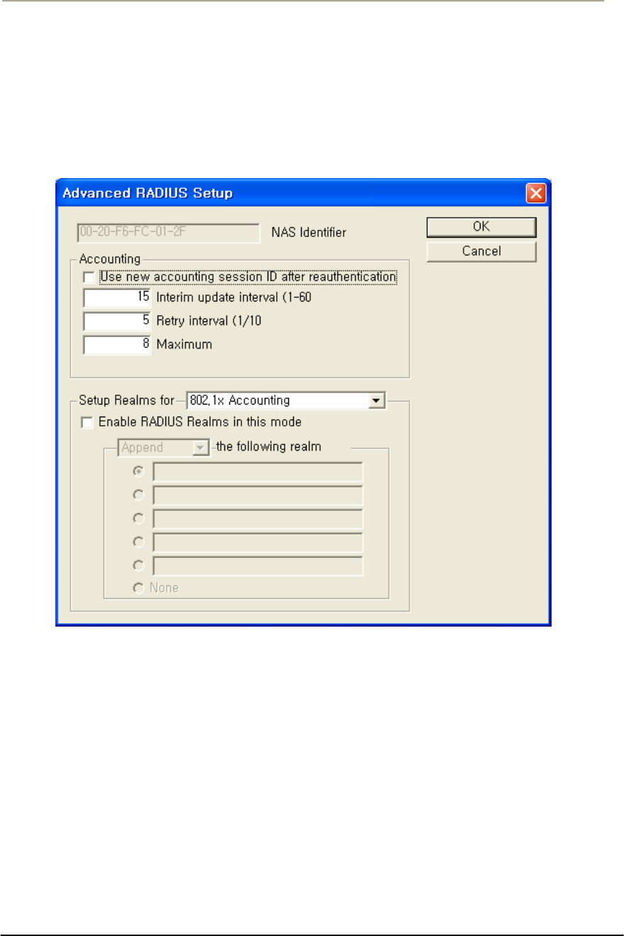
129
Access Point Unit: 2.4G-B-Radio-POE NTPM99AE 01 Rel 1.0 Issue1 May 2007
Configure the APU for Advanced RADIUS MAC Authentication
1. From the MAC RADIUS Setup screen, click the Advanced
RADIUS Settings button. The Advanced RADIUS Setup screen is
displayed, as shown below.
Figure 3-57 Advanced RADIUS Setup Window
The Advanced RADIUS Setup screen is used to configure optional
RADIUS-related parameters.
2. Enter values in the Advanced RADIUS Setup screen, as indicated
by the field descriptions below.
NAS Identifier - This field displays your Network Access Server (NAS)
name. The access point's SNMP System Name is used as the NAS
Identifier, and is shown here for your convenience.
Note: The NAS ID takes the place of the IP address that would normally
be used to identify the AP.

130
Access Point Unit: 2.4G-B-Radio-POE NTPM99AE 01 Rel 1.0 Issue1 May 2007
Use New Accounting Session ID After Authentication -- Select this
checkbox if you wish to use another ID for accounting after
authentication has taken place.
Interim Update Interval -- Set the interval (in minutes) between interim
updates. The interim update is used to send information in between
normal "start/stop" packets. Interim updates are useful because they
provide a log of network traffic at a regular interval.
The default value for the interim update interval is 15 minutes. The
interim update must be between 1 - 60 minutes.
Retry Interval (1/10 sec) -- The retry interval for accounting, in tenths
of a second. The default value is 5 (or a retry interval of .5 seconds).
You can set the retry interval to any value between 3 and 30.
Maximum Retries -- The number of times the access point will retry to
connect with the server. The default value is 8, and the range for retries
is between 1 and 10.
Set Up Realms for -- When an access client sends user credentials, a
user name is often included. Within the user name are two elements:
xIdentification of the user account name
xIdentification of the user account location
For example, for the user name user1@microsoft.com, user1 is the user
account name and microsoft.com is the location of the user account. The
identification of the location of the user account is known as a realm.
With RADIUS, a realm is used to separate one name space from another.
This allows you to create a login such as user@dom1.com and another
login such as user@dom2.com. RADIUS realms also allow Internet
Service Providers (ISPs) to segment customer logins, so authentications
go to the appropriate RADIUS server(s).
A domain is registered with the InterNIC, and used for mapping servers
and services to IP addresses, such as Web, e-mail, etc. Typically, a
RADIUS realm corresponds to a domain name (e.g., microsoft.com;
yahoo.com). However, there is no requirement to do so, and in fact ISPs
often assign realms with no top-level domain (for example, user@dom1 -
- without a .com extension).
From the dropdown list, select the accounting or authorization feature for
which to provide special handling of <RADIUS realms>. Options
currently include:

131
Access Point Unit: 2.4G-B-Radio-POE NTPM99AE 01 Rel 1.0 Issue1 May 2007
xAccess Control List (ACL) RADIUS Accounting
xMAC RADIUS Accounting
xMAC RADIUS Authorization
For each of the above Authentication/Accounting types, special handling
of RADIUS Realms can be enabled or disabled using the "Enabled
RADIUS Realms in this mode" checkbox. Depending on the selected
Authentication/Accounting type, different options are available for how
to handle RADIUS realms.
Following Realm Name -- Select the type of behavior that will be used
for the realm. The behavior determines how the access point handles the
realm. Select one of the following realm types:
Append -- Takes the user supplied user name, and appends the realm
name onto it (for example, if the user name is smith and the realm name
is microsoft.com, then the append action produces
smith@microsoft.com)
Supply -- Supplies the selected realm name if the user does not already
have one selected. If the user provided a realm name, then use the
provided realm name, and do not use the one provided.
xExample #1: User provided smith, Behavior is set to Supply, and
user did not provide a realm name. The supply action produces
jsmith@microsoft.com.
xExample #2: User provided smith, Behavior is set to Supply, and
user provided the realm name yahoo.com. The supply action
produces jsmith@yahoo.com).
Require -- Requires the user to use the selected realm name (or none, if
none is selected). If there is a realm name in the realm name field, the
user must have the realm name indicated by the radio button. If the user
does not, then he or she is not authenticated. If none is selected, then the
user is required not to have a realm name.
xExample #1: User provided smith, Behavior is set to require,
user has the realm name microsoft.com, but yahoo.com is entered
in the realm name field. The user is not authenticated.
xExample #2: User provided smith, Behavior is set to require,
user has the realm name microsoft.com and microsoft.com is
entered in the realm name field. The user is authenticated.)
Force -- Replaces any realm name supplied by the user with the selected
realm name, or strips off the realm name supplied by the user in the case
of none.
xExample: User provided smith, Behavior is set to Force, user
provides the realm name microsoft.com, but yahoo.com is

132
Access Point Unit: 2.4G-B-Radio-POE NTPM99AE 01 Rel 1.0 Issue1 May 2007
entered in the realm name field. The user is authenticated as
jsmith@yahoo.com)
Note: The available behaviors vary depending on the type of accounting
or authorization realm selected. The following table shows the types of
behaviors available for each type of accounting or authorization realm.
Table 3-6 Authentication / Accounting
Type of Accounting/Authorization Realm Behavior(s) Available
ACL Radius Accounting xAppend
MAC RADIUS Accounting xAppend
MAC RADIUS Authentication xAppend
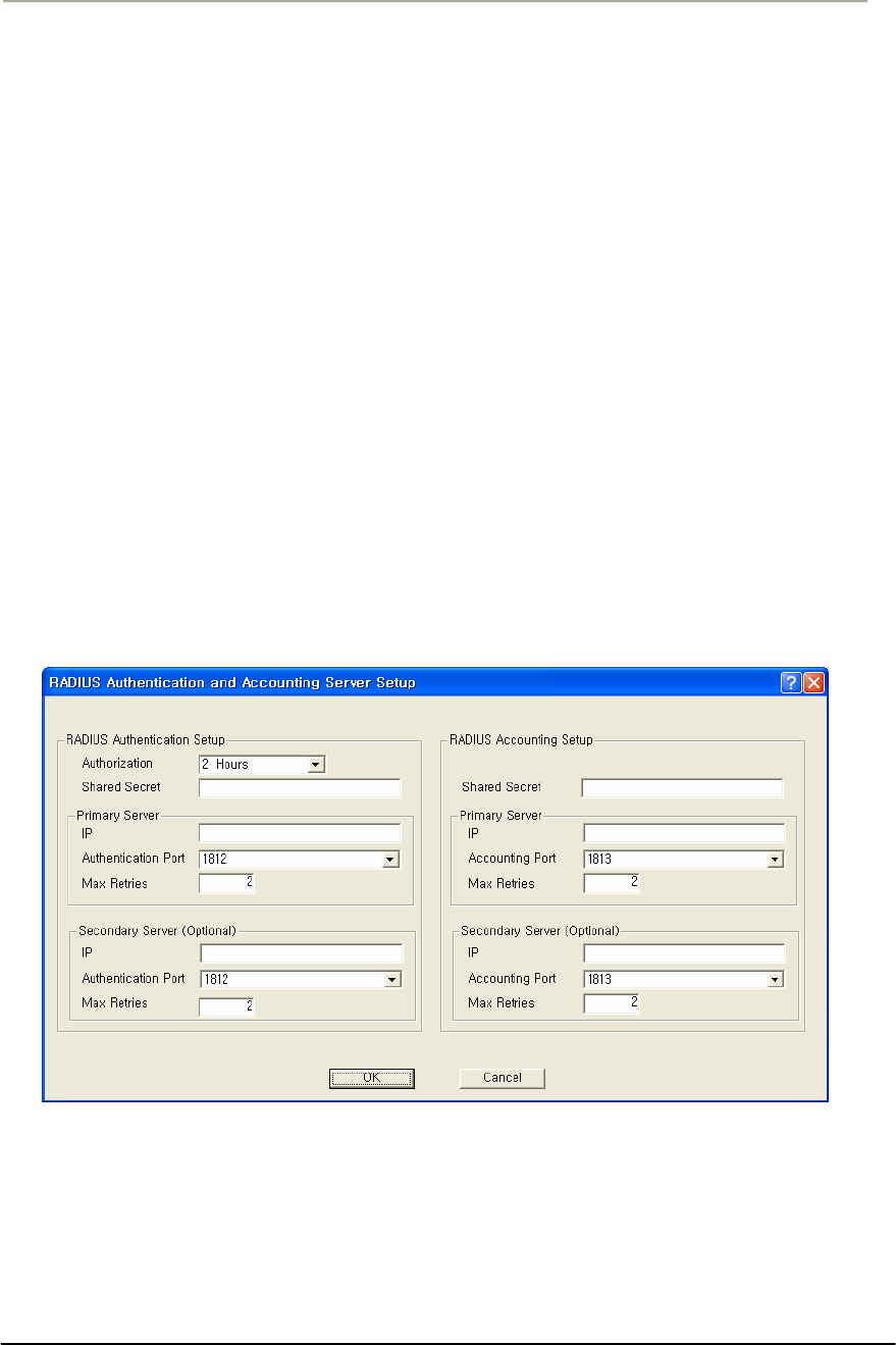
133
Access Point Unit: 2.4G-B-Radio-POE NTPM99AE 01 Rel 1.0 Issue1 May 2007
Configure the RADIUS Server
Once the AP has been configured for basic operation, you are ready to
configure the device for HotSpot Mode and Firewall functionality.
This is a four-step process:
xConfigure the RADIUS Server for Authentication and
Accounting
xConfigure the APU for Basic RADIUS MAC Authentication.
xConfigure the APU for Advanced RADIUS MAC Authentication.
Each step is explained in more detail below. Note that this section
assumes that you have launched the AP Configurator and that you have
completed all steps in Configure the Access Point for Basic Operation
section.
From the Setup tab on the Configurator, click the RADIUS Server button.
The RADIUS Authentication and Accounting Server Setup screen is
displayed, as shown below.
Figure 3-58 RADIUS Setup Window
The RADIUS Server Setup screen is used to configure authentication and
accounting parameters for terminal servers that speak the RADIUS
protocol.
RADIUS is the de-facto standard protocol for authenticating users and
for recording accounting information. Accounting keeps track of the
number of bytes and packets sent by a client. It also keeps track of the

134
Access Point Unit: 2.4G-B-Radio-POE NTPM99AE 01 Rel 1.0 Issue1 May 2007
amount of time a client has been authenticated. It is commonly used by
Terminal Servers or Network Access Servers (NASs) whenever a user
logs on and off a dialup Internet service.
Note: This screen is only available if the MAC Authentication Access
Control button on the General Setup screen has been selected.
There are two main sections in the RADIUS server setup dialog:
RADIUS Authentication Setup and RADIUS Accounting Setup
In most cases you will want to set up both, although you do not have to
set up Accounting. The two are almost identical except for the
Authorization Lifetime, which appears only with Authentication.
To set up RADIUS authentication and accounting:
1. Enter values in the RADIUS Authentication and Accounting Server
Setup screen to configure your RADIUS server. Each field on the
screen is explained in more detail below.
Authorization Lifetime -- Authorization lifetime is the length of time
the authorization is valid. Users will need to be-authenticated/re-
authorized after this time expires. You should set this value to the
maximum time you wish a user to be able to use your service without the
need to be re-authenticated.
Shared Secret -- The client file for your RADIUS server contains the IP
address and password for the base station you are setting up. You must
add the IP address and password (shared secret) from this file in the
RADIUS Server Setup screen.
Note: There are separate shared secrets (passwords) for authentication
setup and accounting setup. The shared secret is an ASCII string that
should be between 2 - 32 characters and should not start with a space.
Primary Server IP Address -- In the RADIUS dialog, enter the IP
address for the RADIUS server (the host).
Primary Server Authentication Port -- In the RADIUS dialog, enter
the authentication port (default = 1812) for the RADIUS server (the host).
Secondary Server IP Address -- If you are using a second RADIUS
server for network robustness, enter the IP address of that RADIUS
server.
Primary Server Accounting Port -- In the RADIUS dialog, enter the
accounting port (default = 1812) for the RADIUS server (the host).

135
Access Point Unit: 2.4G-B-Radio-POE NTPM99AE 01 Rel 1.0 Issue1 May 2007
Secondary Server Authentication Port -- If you are using a second
RADIUS server for network robustness, enter the authentication port
(default = 1812) for that RADIUS server (the host).
Secondary Server Accounting Port -- If you are using a second
RADIUS server for network robustness, enter the accounting port
(default = 1812) for that RADIUS server (the host).
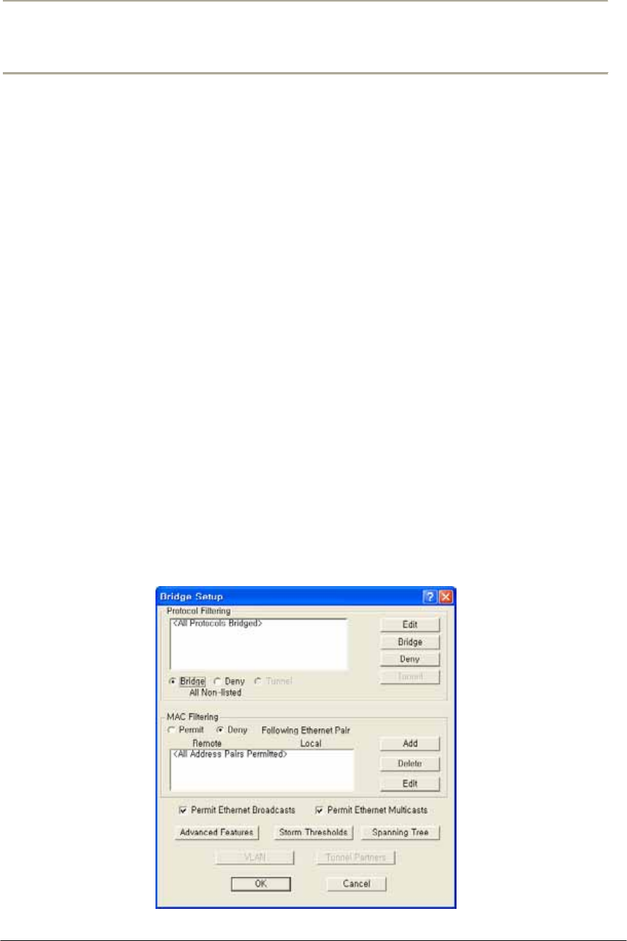
136
Access Point Unit: 2.4G-B-Radio-POE NTPM99AE 01 Rel 1.0 Issue1 May 2007
Procedure 3-7
Advanced and Optional Configuration
Once you have set up the basic network configuration, you may choose
to set up one or more optional or advanced configuration components.
This chapter describes how to configure the following optional and
advanced components:
Set Up the Bridge
The Bridge Setup screen is used to set up the bridge. In addition, you
may use the following screens to set up optional bridge components:
The Bridge Setup screen is used to set up the parameters used for
bridging. In most cases you will not need to modify the factory
configured Bridge Setup. If you are working with an extensive network
environment, however, and if you are an experienced network
administrator, you may want to modify some of the parameters to fit
specific network requirements.
The top half of the screen allows you to define different handling options
based on different protocols. The bottom half of the screen allows you to
define different handling options based on individual MAC addresses.
Note: This screen is only available when the Enable Bridging checkbox
has been selected on the General Setup screen.
Figure 3-59 Bridge Setup window
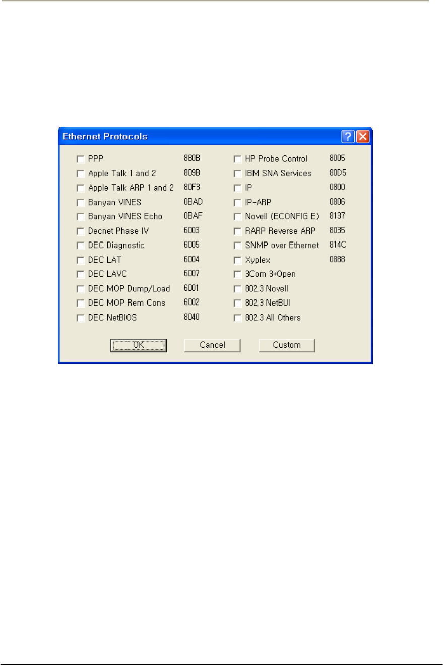
137
Access Point Unit: 2.4G-B-Radio-POE NTPM99AE 01 Rel 1.0 Issue1 May 2007
Protocol Filtering
The Protocol Filtering section of the Bridge Setup screen allows you
to select a handling method (Bridge, Deny, or Tunnel) for the most
common protocols.
Figure 3-60 Protocol Filtering Setup window
1. Select the protocols from the list that you wish to handle separately,
or click the Custom button to add an unlisted protocol. Click the
OK button when finished to re-display the Bridge Setup screen.
Note The protocols you have selected are listed in the Protocol
Filtering window, and that all protocols are denied by default.
2. If you wish to Bridge or Tunnel any of the protocols in the list,
select the protocol, then click either the Bridge or Tunnel buttons
3. At the bottom of the Protocol Filtering list, click the Bridge, Deny,
or Tunnel button to define how all other non-listed protocols
should be handled.
Note: You can add new protocols to the list at any time by clicking the
Edit button and checking additional protocol check boxes.

138
Access Point Unit: 2.4G-B-Radio-POE NTPM99AE 01 Rel 1.0 Issue1 May 2007
Tunnel Button--The Tunnel button is used in conjunction with the
protocols listed in the Protocol Filtering list. Select a protocol from the
list and click the Tunnel button to indicate that the selected protocol
should be tunneled.
Deny Button-- the Deny button is used in conjunction with the protocols
listed in the Protocol Filtering list. Select a protocol from the list and
click the Deny button to indicate that the selected protocol should be
denied.
Bridge Button-- the Bridge button is used in conjunction with the
protocols listed in the Protocol Filtering list. Select a protocol from the
list and click the Bridge button to indicate that the selected protocol
should be bridged.
Bridge MAC Address Filtering Overview
You can specify static MAC Address filters in Bridge Setup to optimize
the performance and increase security on your wireless (and wired)
network. You can permit or deny access to individual stations by
specifying their particular MAC Addresses, or to multiple stations by
using an X as a wildcard character. You can also permit or deny
Ethernet multicast address all traffic that does not match one of the pairs
explicitly listed in the Ethernet pair list will be permitted or denied based
on your selection.
Table 3-7 Traffic Filtering
Selection Traffic Matching Listed Pairs Traffic Not Matching Listed
Pairs
Permit Following Ethernet Pair Permit Deny
Deny Following Ethernet Pair Deny Permit
Stations to be filtered are identified by their MAC Address and whether
they are on a remote or local interface. The Interface parameter indicates
whether the station with the specified MAC Address is located on the
wired or wireless interface of the base station. Use the Add, Delete, and
Edit buttons to modify the entries of the list.
Permit Ethernet Broadcasts-- If you wish to deny broadcast traffic in
your bridged network, deselect this option. Normally, however, you will
select this option to permit Ethernet broadcasts.
Note: This option applies to all Ethernet interfaces, and not simply to
Ethernet traffic.
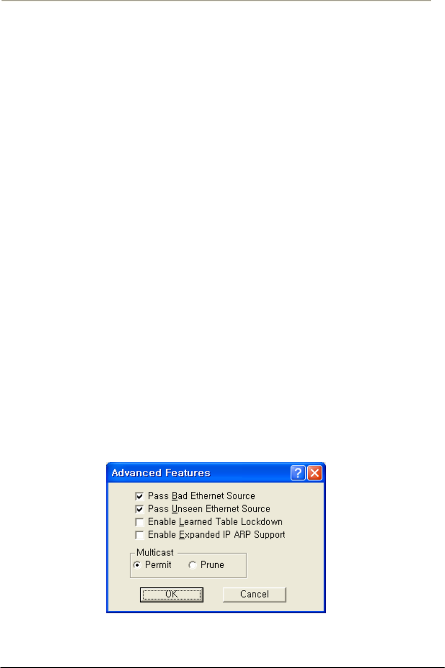
139
Access Point Unit: 2.4G-B-Radio-POE NTPM99AE 01 Rel 1.0 Issue1 May 2007
Permit Ethernet Multicasts-- If you wish to deny multicast traffic in your
bridged network, deselect this option. Normally, however, you will select
this option to permit Ethernet multicasts.
Note: This option applies to all Ethernet interfaces, and not simply to
Ethernet traffic.
Advanced Bridging Features
The Advanced Bridge features can be accessed by clicking the Advanced
Features button on the Bridge Setup screen.
MAC Layer (Ethernet) Filters allow you to filter Ethernet traffic due to
bad or unknown
DHCP Filtering allows you to limit DHCP responses to a particular
DHCP server.
IP/ARP Filtering allows you to prevent unnecessary IP/ARP packets
from being sent over the wireless link.
Incoming Broadcast Filters allow you to prevent broadcast and multicast
packets arriving from the remote interface(s) from being transmitted on
the local interface(s).
Outgoing Broadcast Filters allow you to prevent broadcast and multicast
packets sent from the local interface(s) from being transmitted out the
remote interface(s).
Miscellaneous Statistics Gathering allows you to enable some
miscellaneous advanced bridging features.
Figure 3-61 Advanced Bridging Setup window
Permit Multicast Button-- Select this checkbox if you wish to permit
multicast.

140
Access Point Unit: 2.4G-B-Radio-POE NTPM99AE 01 Rel 1.0 Issue1 May 2007
Prune Multicast Button-- Select this checkbox if you wish to prune
multicast.
Enable Learned Table Lockdown--A standard Bridge/Router watches the
source addresses of each packet it receives on any of its interfaces.
As new addresses are seen, entries are added in the “learned table” that
contain the particular source address and the interface number that
address was received on. If that source address is later seen on a
different interface, the Bridge will immediately change the interface
number in the learned entry table. This condition could happen in a
correctly functioning network if someone moved the computer to a
different part of the network.
This could also happen if someone was trying to capture network packets
by spoofing the Bridge. Enabling learned table lockdown will prevent
the interface number from being changed once the source address has
been seen.
A standard Bridge will also time-out the learned table records every ten
(10) minutes. If learned table lockdown is enabled, these records will not
be timed-out. Once a record is learned, it will not be changed or deleted
until either the Secure Data Mode station reboots or the learned table
becomes completely filled and needs to be reset.
Note: A typical Secure Data Mode learned table can contain over
12,000 records.
Enable Expanded IP/ARP Support
Enabling this feature will cause the Secure Data Mode station to watch
the IP/ARP packets that occur on the network. Normally, no action is
taken in response to an IP/ARP packet that is not destined for a host that
is being Proxy ARPed by the Secure Data Mode station. When this
function is selected, the Secure Data Mode station will add the IP address
to its IP/ARP table when it sees an ARP packet from another source.
This feature is helpful on an ARP network because it will build a
database of MAC layer address to IP address pairs.
Note: The IP/ARP table is never timed out in this mode.
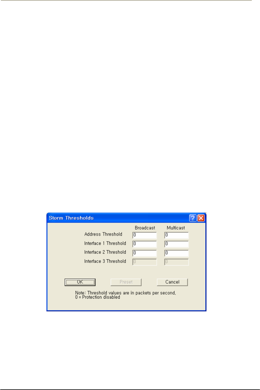
141
Access Point Unit: 2.4G-B-Radio-POE NTPM99AE 01 Rel 1.0 Issue1 May 2007
Storm Threshold Setup
The Storm Thresholds screen is used to set threshold values for broadcast
and multicast messages.
In most situations, you will not need to set the Storm Thresholds.
However, if intensive multicast or broadcast messaging is typical of the
network protocols used in your network environment, you may wish to
control the maximum number of broadcast and multicast messages. If the
maximum value of broadcast or multicasts per second is exceeded, the
Secure Data Mode Station will ignore all subsequent messages issued by
the particular network device, or ignore all messages of that type coming
on that particular interface.
You can use the Storm Threshold screen to:
Specify a maximum value as received from a single network device
(identified by its MAC address).
Specify an absolute maximum of messages per second per Interface.
You can specify a set of thresholds for each Interface of the Secure Data
Mode Station access point, identifying separate values for the number of
Broadcast messages/second and Multicast messages/second.
Figure 3-62 Broadcast Storm Setup window
Broadcast Address Threshold
Enter the maximum number of broadcast messages per second that will
be received from a single network device (identified by its MAC
address).

142
Access Point Unit: 2.4G-B-Radio-POE NTPM99AE 01 Rel 1.0 Issue1 May 2007
Multicast Address Threshold-- Enter the maximum number of
multicast messages per second that will be received from a single
network device (identified by its MAC address).
Broadcast Interface 1 Threshold-- Enter the maximum number of
broadcast messages per second that will be received on Interface 1
(typically Ethernet).
Multicast Interface 1 Threshold-- Enter the maximum number of
multicast messages per second that will be received on Interface 1
(typically Ethernet).
Broadcast Interface 2 Threshold-- Enter the maximum number of
broadcast messages per second that will be received on Interface 2
(typically 802.11).
Multicast Interface 2 Threshold-- Enter the maximum number of
multicast messages per second that will be received on Interface 2
(typically 802.11).
Broadcast Interface 3 Threshold-- Enter the maximum number of
broadcast messages per second that will be received on Interface 3
(typically 802.11a).
Multicast Interface 3 Threshold-- Enter the maximum number of
multicast messages per second that will be received on Interface 3.
Preset Button-- Clicking the Preset button sets all broadcast and
multicast rates to their default values. The default values are as follows:
Table 3-8 Default Threshold values
Item Broadcast Multicast
Address Threshold 30 30
Interface1 Threshold 60 60
Interface2 Threshold 60 60
Interface3 Threshold 60 60
Spanning Tree Setup
The Spanning Tree Setup screen allows you to configure your bridges so
that they will dynamically discover a loop-free subset of the LAN
topology (a tree), that provides the most efficient level of connectivity
between every pair of physically connected Local Area Network
segments. See Spanning Tree for more information about how the
spanning tree algorithm works. The default settings for the Spanning
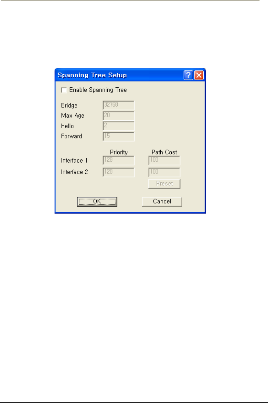
143
Access Point Unit: 2.4G-B-Radio-POE NTPM99AE 01 Rel 1.0 Issue1 May 2007
Tree Algorithm will provide satisfactory performance for most Local
Area Network (LAN) topologies.
Enable Spanning Tree -- Select this checkbox if you wish to enable
Spanning Tree capabilities.
Figure 3-63 VLAN Spanning Tree Setup window
Bridge Priority -- The Bridge Priority parameter allows you to influence
the choice of the Root Bridge and Designated Bridge as calculated by the
Spanning Tree Algorithm.
Valid Values: 0 - 65000
Default: 32768
A low numerical value makes the bridge more likely to become the
designated bridge or root bridge (typically 0).
The recommended value is 32768.
You may assign a duplicate priority value to multiple bridges, provided
that it is a non-zero value. Bridges that have an identical Bridge Priority
level are typically not intended to function as the root bridge.
Max Age -- The Max Age parameter identifies the maximum age of
received Spanning Tree protocol information.
When the bridge receives protocol information that exceeds the Max Age
value, the bridge will discard the information and start the Forward
Delay timer to allow other bridges to forward updated topology

144
Access Point Unit: 2.4G-B-Radio-POE NTPM99AE 01 Rel 1.0 Issue1 May 2007
information (for example, that another bridge has become the Root
Bridge).
Note: Recommended Value (20 seconds)
A low Max Age value occasionally may cause the Spanning Tree to
reconfigure unnecessarily, resulting in temporary loss of connectivity
throughout the network.
A high Max Age value will cause the LAN to take longer than necessary
to rebuild the Spanning Tree whenever a link or bridge unit breaks down
or becomes available again.
Hello Time -- The Spanning Tree Hello Time parameter identifies the
time interval between Configuration PBDU transmitted by a root bridge,
or a bridge that is attempting to become the root bridge.
Note: Recommended Value (2 seconds)
Shortening the Hello Time will make the protocol more robust,
especially when the probability of loss of configuration messages is high.
Lengthening the Hello Time will lower the overhead of the algorithm
since the interval between the transmissions of configuration messages
will be longer.
Forward -- The Forward Delay is a timer that prevents a bridge to
forward data packets when:
xThe bridge receives information that the active Spanning Tree
topology must be updated (for example when a bridge breaks down
or when somebody modified the Bridge Priority or Path Cost value of
a particular bridge).
xThe bridge registers that the protocol information exceeds the
specified Max Age value.
xChanges in the Spanning Tree topology must be communicated to all
bridges in the bridged network. The Forward Delay timer will
compensate for the propagation delays that occur in passing the
protocol information, allowing all bridges to close the old data paths,
before the new data paths are activated.
Note: Recommended Value (15 seconds)
A lower value may result in temporary loops as the Spanning Tree
Algorithm converges.
A higher value may result in longer partitions after the Spanning Tree
reconfigures.

145
Access Point Unit: 2.4G-B-Radio-POE NTPM99AE 01 Rel 1.0 Issue1 May 2007
Port Priority-- Normally the Bridge Port priority in Spanning Tree
topologies is imposed by the Root Bridge and the applicable values of
the Path Cost to the Root Bridge.
When concurrent bridge ports of a single bridge unit are connected in a
loop, this parameter enables you to influence which port should be
included in the Spanning Tree.
Valid Values: 0 - 255
Default: 128
A lower value makes a port more likely to become selected in the
Spanning Tree than the concurrent one that has a higher numerical value.
A higher value makes a port less likely to be selected in the Spanning
Tree than a port with a lower numerical value.
Path Cost-- The Path Cost value is used to determine the preferred data
paths between bridges throughout the network and the root bridge.
The Root Bridge transmits BPDU messages throughout the Local Area
Network. When a bridge unit receives a BPDU message at one of its
ports, it will add the value in the Path Cost field for that port to the value
in the Root Path Cost Field of the BPDU message before forwarding the
message again. This will help the other bridges to determine the Total
Path Cost to the Root Bridge via this port.
Valid Values: 0 - 255
Default: 100
A lower Path Cost value would typically be used for ports to LAN
segments closer to the Root Bridge.
A higher Path Cost value would typically be used for ports to LAN
segments that are the "leafs" of the Spanning Tree.
For example, when using the Secure Data Mode Station as an access
point for wireless stations to the Ethernet, a high Path Cost for the
wireless interface will minimize unnecessary use of the bandwidth for
the wireless medium (recommended value 255).
When using Secure Data Mode Stations in a wireless point-to-point link
to interconnect two LAN segments, a low Path Cost for the wireless
interface will prioritize this link as compared to other physical links, such
as a leased line or low-bandwidth connections.
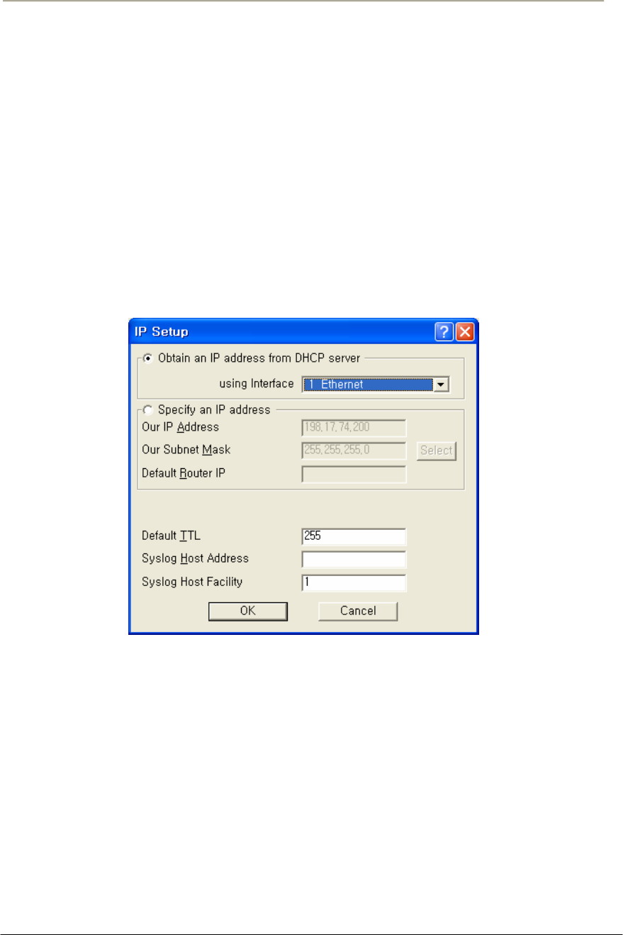
146
Access Point Unit: 2.4G-B-Radio-POE NTPM99AE 01 Rel 1.0 Issue1 May 2007
Set Up IP for APU and CSU
The IP Setup screen allows you to set the Secure Data Mode Station's IP
Addressing information. The Secure Data Mode Station must have an IP
address assigned to it if you wish to connect to it using the Configuration
tool, which makes use of SNMP to connect to the Secure Data Mode
Station.
Note: This screen is only available when the Enable IP Routing, Enable
Outgoing Network Address Translation, and Enable Incoming Network
Address Translation checkboxes been de-selected on the General Setup
screen.
Figure 3-64 IP Setup window
You can choose to set up the base station to obtain an IP address from
DHCP server. If you select this option, you must also choose the
interface on which you would like the base station to send the request.
This option causes your base station to send a broadcast request for its IP
address, subnet mask, and default router over the given interface at base
station startup time. If you select the DHCP option, it is recommended
(though not required) that you set up your DHCP server to always
provide the same IP address to this Secure Data Mode Station system.
You can also manually specify an IP Address to set the IP Address for
the base station yourself:
You can set the life expectancy for packets originating from this Secure
Data Mode Station using the Default TTL (Time to Live) field.

147
Access Point Unit: 2.4G-B-Radio-POE NTPM99AE 01 Rel 1.0 Issue1 May 2007
You can use syslog messages to log information such as logins, service
errors and general configuration information. Since there is no storage
on a base station, a general purpose computer is needed to log these
messages. To set the syslog host that will accept syslog messages, use
the Syslog Host Address and Syslog Host Facility fields.
Obtain an IP Address from DHCP Server-- Select this radio button if
you wish to obtain an IP address from the DHCP Server.
If you select this option, you must also choose the interface on which
you would like the base station to send the request. This option causes
your base station to send a broadcast request
For its IP address, subnet mask, and default router over the given
interface at base station startup time. If you select the DHCP option, it is
recommended (though not required) that you set up your DHCP server to
always provide the same IP address to this Secure Data Mode Station
system.
Using Interfaces-- Select the interface for which you wish to obtain an
IP address. A base station has several network interfaces to which it may
be connected. The network interfaces are numbered (1, 2, 3...), and the
interface numbers may be found by selecting Interface Setup from the
Setup Menu.
Specify an IP Address-- Select this radio button if you wish to enter an
IP address manually.
Our IP Address-- This is the address of the Secure Data Mode
Bridge/Router itself. If you wish to configure or monitor your Secure
Data Mode Bridge/Router, or if your network supports IP and you wish
to enable the Ping support and IP/SNMP support of the Secure Data
Mode Bridge/Router, set this to a valid IP address. After setting this
address to 0.0.0.0, enter the IP address of the base station.
Please note that unless you enable IP Routing on the IP Router Setup
screen, the Bridge/Router is not an IP router. It has only one IP address,
and that address applies to both the remote and local networks (i.e., both
sides of the Bridge). Having two Ethernet interfaces with the same IP
address is different than a standard IP host, but is appropriate for a
Transparent Bridge. The Ethernet address of both interfaces is also the
same.
Note: This field is only enabled when the Specify an IP Address radio
button has been selected.

148
Access Point Unit: 2.4G-B-Radio-POE NTPM99AE 01 Rel 1.0 Issue1 May 2007
Our Subnet Mask-- Enter the subnet mask for the base station.
Note: This field is only enabled when the Specify an IP Address radio
button has been selected.
Default Router IP-- Enter the IP address of the router.
Note: This field is only enabled when the Specify an IP Address radio
button has been selected.
Select Button-- Clicking this button displays the IP Mask List screen,
which allows you to select a particular IP mask.
IP Mask List-- The IP Mask List window displays a list of common IP
subnet masks for a given size IP subnet.
Default TTL-- The Time To Live (TTL) counter avoids endless
forwarding of message frames with incorrect addressing by defining a
maximum number of hops a packet can take. Each time the frame is
forwarded by a router, the TTL counter decreases by one.
When the TTL = 0, the frame is rejected.
Syslog Host Address-- Syslog messages can be used to log information
such as logins, service errors and general configuration information.
Since there is no storage on a base station, a general purpose computer is
needed to log these messages.
The Syslog Host Address is the IP Address of the system which accepts
"syslog" system logging packets from the base station.
Syslog Host Facility
Syslog messages can be used to log information such as logins, service
errors and general configuration information. Since there is no storage
on a base station, a general purpose computer is needed to log these
messages.
The Syslog Host Facility describes the part of the system generating the
syslog message, and in UNIX-based systems usually uses one of the
following keywords: auth, authpriv, cron, daemon, kern, lpr, mail, mark,
news, syslog, user, uucp, and local0 through local7.
The base station is capable of sending messages using the local0-local7
facilities. Enter the correct syslog facility number (0-7) that corresponds
to the local facility type on your syslog host.
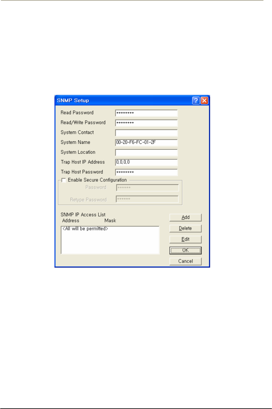
149
Access Point Unit: 2.4G-B-Radio-POE NTPM99AE 01 Rel 1.0 Issue1 May 2007
Set Up SNMP
The SNMP Setup screen allows you to manage a network environment
that includes multiple base stations where you can use the Simple
Network Management Protocol (SNMP).
SNMP setup allows you to create multiple authorization levels for
network management that are password protected.
Figure 3-65 SNMP Setup window
Read Password-- This password enables you to create a network
management level where a local LAN Administrator can view, but not
modify, the SNMP parameters.
Read/Write Password-- This password enables you to create a network
management level where only a Network Supervisor knowing the right
Read/Write password will be able to view or modify the SNMP
parameters.
Contact-- Optionally, enter the name or address of the Network
Administrator.

150
Access Point Unit: 2.4G-B-Radio-POE NTPM99AE 01 Rel 1.0 Issue1 May 2007
System Name-- Optionally, enter the logical location of a base station
(for example, the network segment to which the base station has been
connected).
System Location-- The optional field to identify the physical location of
a base station. For example, the building or room where the base station
is located at
Trap Host IP Address-- The IP Address of the network management
station that collects the SNMP Trap messages.
The Trap Host is the station in an SNMP managed network where SNMP
trap messages are collected. Trap messages are sent to the trap host when
certain events occur, such as rebooting.
Trap Host Password-- The Trap Host is the station in a SNMP managed
network where SNMP trap messages are collected. Trap messages are
sent to the trap host when certain events occur, such as rebooting.
Enter a password that corresponds to the password set at the Trap Host to
filter unsolicited or unauthorized SNMP Trap messages at the Trap Host.
The Trap Host IP Password will be embedded in the SNMP Trap
messages sent by this base station. If the Trap Host receives a message
without or with an unknown password, the Trap message will be ignored.
SNMP IP Access List-- The SNMP IP Access List displays the IP
addresses and subnet masks of those stations that you have designated as
stations that will manage networks using SNMP.
In addition to the Read and Read/Write passwords, you can use the
SNMP Access List to prevent unauthorized users from modifying the
SNMP setup of your base stations.
The SNMP IP Access List enables you to authorize SNMP management
to a restricted group of SNMP Management stations identified by:
The unique IP address of the Management Station(s)
The interfaces via which the base station will be accessed.
Click the Add button to display the Input SNMP Access List to add new
IP addresses to the list.
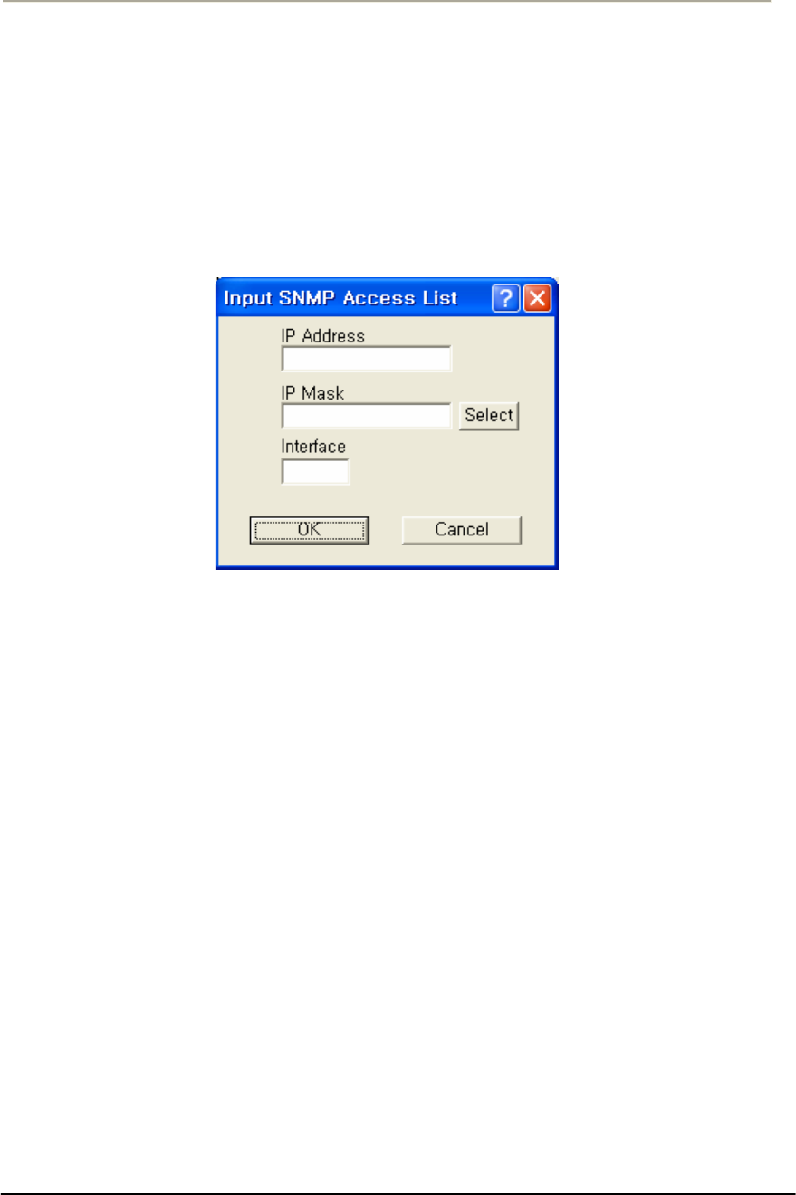
151
Access Point Unit: 2.4G-B-Radio-POE NTPM99AE 01 Rel 1.0 Issue1 May 2007
Input SNMP Access List Dialog - Overview
Clicking the Add button displays the SNMP Access List Dialog, which
allows you to enter the IP addresses and subnet masks of those stations
that you have designated as stations that will manage networks using
SNMP.
Figure 3-66 Input SNMP Setup window
IP Address-- The unique IP address of the SNMP management station
you wish to add or edit.
IP Mask-- Enter the Subnet mask, or clicks the Select button to display
the IP Mask List and select a mask from the list.
Note: A subnet mask value of 255.255.255.255 will authorize only the
station with the address specified in the IP address. A subnet mask value
of 255.255.255.0 will authorize all stations that have an IP address
within the range of that particular subnet (the IP address field will
display the value xxx.xxx.xxx.0).
Warning: The subnet mask value 0.0.0.0 will authorize any station to
view or modify SNMP IP setup of the base station via the interface
identified in the Interface field.
Interface-- The number of the interfaces over which packets on this
route is sent.
Select Button-- Clicking this button displays the IP Mask List screen,
which allows you to select a particular IP mask.
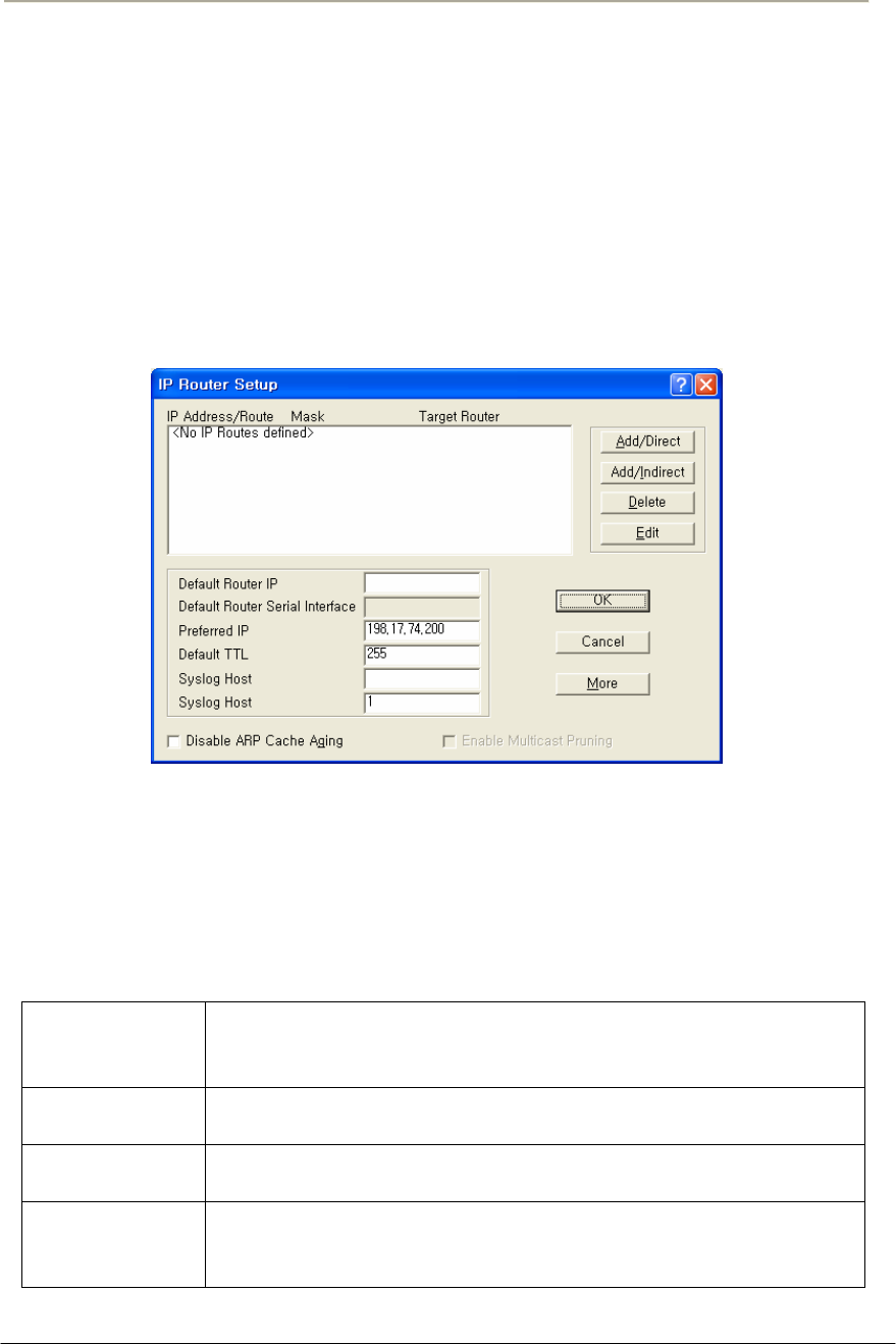
152
Access Point Unit: 2.4G-B-Radio-POE NTPM99AE 01 Rel 1.0 Issue1 May 2007
Set Up IP Routing
The IP Router Setup screen is used to set up IP Routing. This enables the
base station to send IP packets to the appropriate subnet or router. Once
you have set up the basic IP Router configuration, you may also want to
set up the following optional components:
Note: This option is only available if the Enable IP Routing checkbox
on the General Setup screen has been selected.
Figure 3-67 IP Router Setup window
IP Route List
This pane displays the list of IP Routes that this Router has been
configured to use. To add additional direct or indirect routes, click on the
Add/Direct or Add/Indirect buttons.
Table 3-9 IP Route List
IP Route List This pane displays the list of IP Routes that this Router has been
configured to use. To add additional direct or indirect routes,
click on the Add/Direct or Add/Indirect buttons.
Mask The Subnet Mask of the IP Address, which shows which
addresses should be routed using this route.
Target For a Direct Route, the word Direct appears in this field. For an
Indirect Route, this field shows the Default Router.
Interface/Cost For direct routes, the interface to use when sending packets
using this route. For indirect routes, the cost metric of using this
route (used to determine the best route to use for a given packet).

153
Access Point Unit: 2.4G-B-Radio-POE NTPM99AE 01 Rel 1.0 Issue1 May 2007
Default Router IP Address-- Enter the IP Address of the router that the
base station should use to communicate with networked devices outside
its current subnet.
Default Router Serial Interface-- The Secure Data Mode station has
several network interfaces to which it may be connected. An interface
number is required for the Secure Data Mode station to know which
interface to use to send packets addressed to a given destination. This
field displays the serial interface that the router will use by default.
Preferred IP Address-- From time to time, the Secure Data Mode
Bridge/Router will transmit unsolicited IP packets such as SNMP traps,
Syslog, RIP, or IP/ARP packets. Most routers randomly use one of the IP
addresses from one of the router interfaces as the source IP address for
these packets. However, in the Preferred IP Address field, you can
specify the source IP address that you prefer to use for these packets.
Default TTL-- The Time To Live (TTL) counter avoids endless
forwarding of message frames with incorrect addressing by defining a
maximum number of hops a packet can take. Each time the frame is
forwarded by a router, the TTL counter decreases by one. When the TTL
= 0, the frame is rejected.
Syslog Host Address-- Syslog messages can be used to log information
such as logins, service errors and general configuration information.
Since there is no storage on a base station, a general purpose computer is
needed to log these messages.
The Syslog Host Address is the IP Address of the system that accepts
"syslog" system logging packets from the base station.
Syslog Host Facility-- Syslog messages can be used to log information
such as logins, service errors and general configuration information.
Since there is no storage on a base station, a general purpose computer is
needed to log these messages.
The Syslog Host Facility describes the part of the system generating the
syslog message, and in UNIX-based systems usually uses one of the
following keywords: auth, authpriv, cron, daemon, kern, lpr, mail, mark,
news, syslog, user, uucp, and local0 through local7.
The base station is capable of sending messages using the local0-local7
facilities. Enter the correct syslog facility number (0-7) that corresponds
to the local facility type on your syslog host.
Disable ARP Cache Aging-- Select this checkbox to stop the Address
Resolution Protocol (ARP) table from removing entries after a certain
period of time. The IP ARP table relates each (wired or wireless)

154
Access Point Unit: 2.4G-B-Radio-POE NTPM99AE 01 Rel 1.0 Issue1 May 2007
station's IP address to its physical MAC Address so the base station
knows how to address Ethernet messages bound for a particular IP
Address. If you disable (uncheck) ARP cache aging, the base station will
not remove entries from this table, and it may fill up over time. The base
station can hold up to 10,000 entries in the ARP table.
Enable Multicast Pruning-- Select this checkbox if you want to enable
multicast pruning.
IP multicast is a bandwidth-conserving technology that reduces traffic by
simultaneously delivering a single stream of information to potentially
thousands of corporate recipients and homes.
Without multicast pruning, multicast traffic is treated in the same manner
as broadcast traffic. That is, it is forwarded to all ports. However, with
multicast pruning, you choose to permit only the packets that are a part
of multicast group in your network. Multicast pruning generates no
additional network traffic, allowing you to significantly reduce multicast
traffic passing through your switch.
Add Direct IP Routes
Clicking the Add/Direct button displays the Add Direct IP Route screen,
which allows you to add new direct IP routes.
When the Secure Data Mode station has two or more IP subnets directly
attached to its different interfaces, it can route IP packets between those
subnets using a direct route. This screen is used to specify the direct
routes for each of the interfaces on the Secure Data Mode Bridge/Router.
A direct route consists of an IP address, which specifies the basic IP
address to route, a Subnet Mask which defines the basic class of IP
addresses that will be routed, and an interface number which specifies
where the IP subnet is attached. When IP packets addressed to a system
arrives at the Secure Data Mode station, the Secure Data Mode station
will send it directly to the target machine on the interface specified.
Figure 3-68 Direct IP Route Setup window

155
Access Point Unit: 2.4G-B-Radio-POE NTPM99AE 01 Rel 1.0 Issue1 May 2007
IP Address-- The IP address specifies the basic IP address to route.
IP Mask-- The Subnet Mask which defines the basic class of IP
addresses that will be routed. Clicking the Select button displays the IP
Mask List, which the shows the IP Masks that can be used as public or
private IP masks for IP routing. The list consists of all possible subnet
masks, and represents the range of addresses that will be translated.
Interface-- An interface number specifies where the IP subnet is
attached.
Add Indirect IP Routes
The Add Indirect IP Route screen is used to add indirect IP routes.
When the base station needs to send IP packets between IP subnets
which are not directly connected to one of its interfaces (i.e., not on the
same network segment), it must have an indirect route for sending those
packets.
An indirect route consists of:
An IP Address which specifies the basic IP address to route,
A Subnet Mask which defines the class of IP addresses that will be
routed,
A Target Router that will relay the IP packet, and
A Cost value, which specifies the number of "hops" required for the
indirect route.
When an IP packet addressed to a system on the indirectly routed subnet
arrives at the base station, the base station will route it over the interface
specified to the Target Router to be further routed.
Figure 3-69 Indirect IP Route Setup window
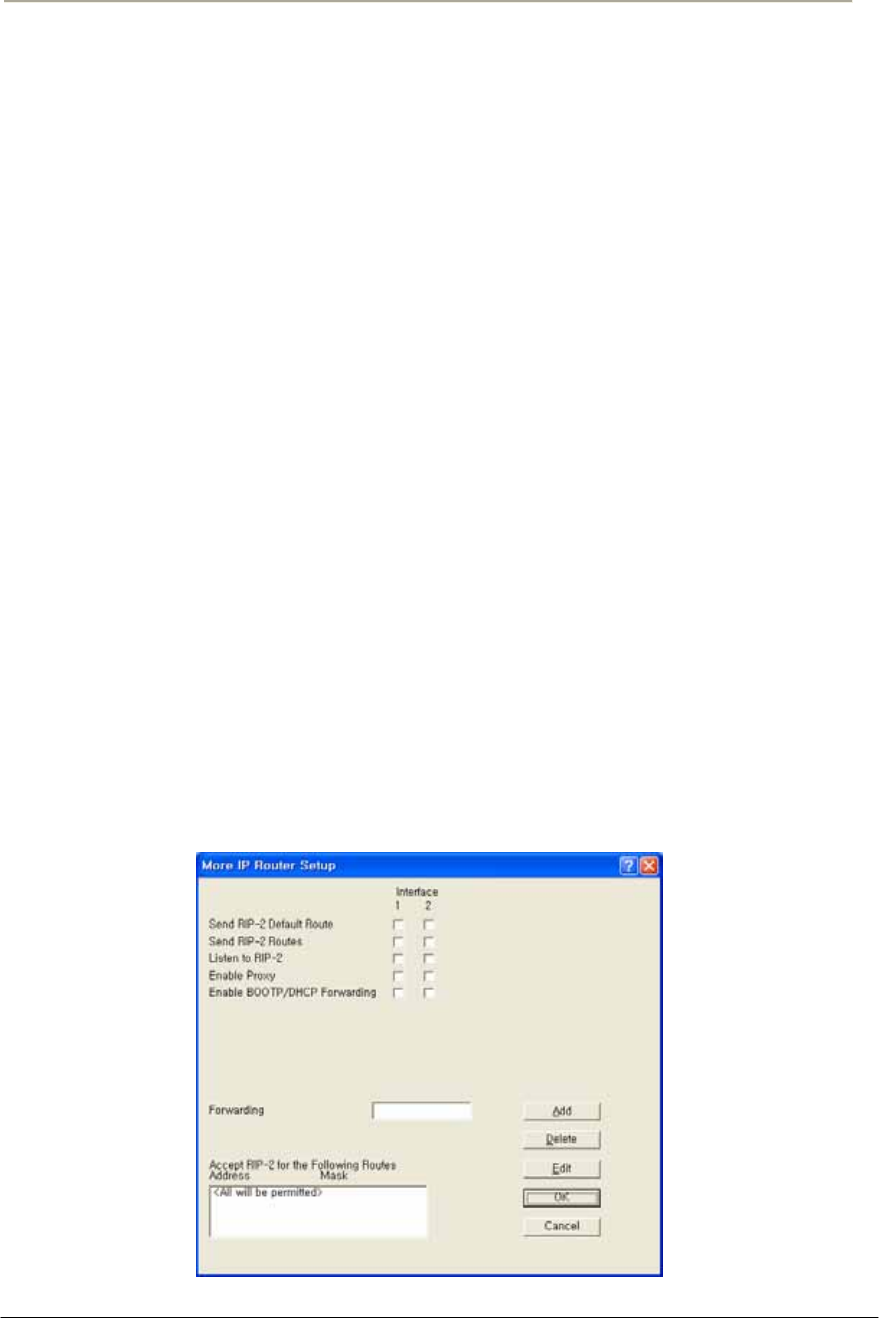
156
Access Point Unit: 2.4G-B-Radio-POE NTPM99AE 01 Rel 1.0 Issue1 May 2007
IP Address-- The IP Address which specifies the basic IP address to
route.
IP Mask-- Enter the IP subnet mask for the IP address to be routed, or
click the Select button and choose a subnet mask from the list. Clicking
the Select button displays the IP Mask List, which the shows the IP
Masks that can be used as public or private IP masks for IP routing. The
list consists of all possible subnet masks, and represents the range of
addresses that will be translated.
Target Router-- Enter the IP address of the router that you wish to use
as the target router.
A target router is the IP address of the router that knows how to handle
the IP packet that is being routed. When used in indirect routes, it could
specify the router that is attached directly to the subnet of the packet's
final destination, or a router that knows where to send it.
Cost-- The cost value reflects the number of "hops" required for the
connection. The default value of 1 indicates that only one "hop" is
required. The lower the cost value, the more likely that route will be
chosen.
Advanced IP Routing Setup
The More IP Router Setup screen is used to set up advanced IP router
interfaces.
Figure 3-70 Advanced IP Routing Setup window

157
Access Point Unit: 2.4G-B-Radio-POE NTPM99AE 01 Rel 1.0 Issue1 May 2007
Send RIP-2 Default Route-- If the base station sends the Routing
Information Protocol (RIP) default route (0.0.0.0) to other routers and
hosts attached to a particular interface, select that interface's checkbox on
the Send RIP Default Route line. By default, the base station will not
send the Default Route on a particular interface unless this box is
checked.
In the example shown in the screenshot, the base station will send RIP
routes only on interfaces 1 and 2.
Send RIP-2 Routes -- If the base station should SEND Routing
Information Protocol (RIP) Routes for routes of which it has knowledge
to other routers on a particular interface, select that interface's checkbox
on the Send RIP Routes line. By default, the base station will not send
RIP Routes on a particular interface unless this box is checked.
For the given example, the base station will send RIP Routes only on
interface 1.
Listen to RIP-2-- If the base station should ACCEPT Routing
Information Protocol (RIP) routes from other routers on a particular
interface, select that interface's checkbox on the Listen to RIP line. By
default, the Secure Data Mode Station will not accept RIP Routes from
other routers, so you must select the interfaces if you wish to listen to
RIP. For the given example, the Secure Data Mode Station will listen to
RIP Routes on Interfaces 1 and 2, but will not accept RIP routes sent to it
on interface 3.
Enable Proxy ARP-- Enabling Proxy ARP for a particular interface tells
the base station that when it receives an ARP request for a particular
client connected by that interface, that the base station itself should
respond to the ARP Request, fulfilling the request with information that
is in its IP ARP Table.
For example, Proxy ARP is enabled on interface 2. The IP ARP Table
contains (among others) the following entry:
Table 3-10 IP ARP Table
Interface Physical Address IP Address Media Type
2 00:60:1d:04:4d:88 10.7.3.5 dynamic
Since Proxy ARP is enabled for interface 2, when the base station
receives a broadcast ARP Request for 10.7.3.5, instead of passing the
ARP on to 10.7.3.5, the base station will answer the request with
information its own IP ARP table, that is: IP Address 10.7.3.5 -> MAC
Address 00:60:1d:04:4d:88.

158
Access Point Unit: 2.4G-B-Radio-POE NTPM99AE 01 Rel 1.0 Issue1 May 2007
Proxy ARP is useful in many situations to reduce unnecessary network
traffic, but is especially useful when you have clients in power-save
mode, to prevent them from being 'woken up' whenever an ARP is done.
Enable BOOTP/DHCP Forwarding -- Select the interfaces for which
you would like the base station to forward BOOTP and DHCP requests
on to the BOOTP/DHCP server, which is specified in 'Forwarding Host’.
Forwarding BOOTP and DHCP requests is necessary when the
BOOTP/DHCP clients are not on the same IP subnet as the
BOOTP/DHCP server.
If you are using BOOTP/DHCP, forwarding should most likely be
DISABLED for the interface through which the BOOTP/DHCP server is
located, and ENABLED for the other interfaces.
In the displayed screen, the BOOTP/DHCP Server is located via
interface 1, so forwarding is enabled for interfaces 2 and 3, since clients
on interfaces 2 and 3 have no other way of accessing the BOOTP/DHCP
server.
Forwarding Host -- If you have enabled BOOTP/DHCP forwarding for
one or more interfaces, enter the IP address of the BOOTP/DHCP server
or relay agent to which you should forward BOOTP/DHCP requests.
In this example, the BOOTP/DHCP Forwarding host is 10.2.3.1.
Accept RIP-2 for the Following Routes-- In addition to the other
Advanced IP Router features which allow you to accept RIP routes from
particular interfaces, you can specify which RIP Routes you would like
to accept. You are also able to specify the interfaces from which you
would like to accept those particular RIP Routes.
The base station will accept RIP only for three particular routes. In the
More IP Router Setup screen, it was specified that the base station should
listen to RIP Routes on interfaces 1 and 2. This section further specifies
that the base station should listen to the following RIP Routes ONLY:
10.17.42.0 (mask 255.255.255.0) only if it comes from interface 1
10.20.24.0 (mask 255.255.248.0) only if it comes from interface 2
10.220.23.0 (mask 255.255.255.0) on any interface
All other RIP routes will be ignored.
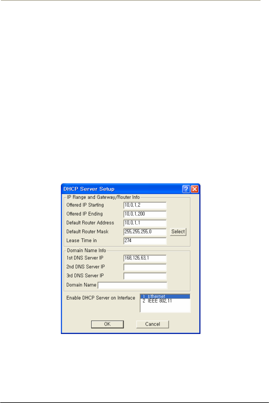
159
Access Point Unit: 2.4G-B-Radio-POE NTPM99AE 01 Rel 1.0 Issue1 May 2007
DHCP Server Setup
The DHCP Server Setup screen is used to set up the base station's
Dynamic Host Configuration Protocol (DHCP) Server feature. The
DHCP Server feature is a basic DHCP Server that can enable any and all
wireless (or other) clients that connect to the base station to obtain their
IP Address information from this Secure Data Mode.
Warning: If you have set up the base station to Obtain IP Address from
DHCP Server on the IP Host Setup screen, do not enter anything in the
Domain Name Info section of this screen. When the base station gets its
own IP Address by DHCP, it will automatically determine the correct
Domain Name information. You should, however, set up the IP Range
and Gateway/Router Info section and select the correct interface.
Note: This screen is only available when the Enable DHCP Server
checkbox has been selected on the General Setup screen.
Figure 3-71 DHCP Server Setup window
Offered IP Address-- Enter the beginning and ending IP addresses for
the IP address range that the Secure Data Mode Station should offer to
DHCP clients. When DHCP requests are received by the Secure Data
Mode Station, it will offer the IP Starting Address to the first client, and
increment the IP address offered to each consequent DHCP client until it
reaches the IP Ending Address. IP Address leases must be renewed by

160
Access Point Unit: 2.4G-B-Radio-POE NTPM99AE 01 Rel 1.0 Issue1 May 2007
the DHCP client within the given Lease Time, or the IP Address will be
made available to another client.
Note: The Secure Data Mode Station does NOT store DHCP address
assignments between restarts. If the Secure Data Mode Station is
rebooted, it will ARP for each address in the provided address range,
recording which client is using which IP address.
Note: Be careful not to include the default router's IP address in the
Offered IP Address range.
Default Router Address-- Enter the default router IP address for the
Secure Data Mode Station's DHCP clients.
Note: The default router IP address must be outside of the range defined
by the Offered IP Starting Address and Offered IP Ending Address.
Default Router Mask-- Enter the subnet mask for the default router, or
click the Select button to display the IP Mask List, and select a subnet
mask from the list.
Lease Time in Minutes-- A DHCP lease is the amount of time that the
DHCP server grants permission to the DHCP client to use a particular IP
address. Enter the lease time (in minutes) for your DHCP server.
DNS Server IP Addresses-- Enter the IP address for the DNS server.
Warning: If you have set up the base station to Obtain IP Address from
DHCP Server on the IP Host Setup screen, do not enter any DNS server
IP addresses or a domain name. When the base station gets its own IP
Address by DHCP, it will automatically determine the correct Domain
Name information. You should, however, set up the IP Range (IP
starting and ending addresses) and Gateway/Router Info section and
select the correct interface.
Domain Name-- Enter the name of the domain.
Warning: If you have set up the base station to obtain IP Address from
DHCP Server on the IP Host Setup screen, do not enter any DNS server
IP addresses or a domain name. When the base station gets its own IP
Address by DHCP, it will automatically determine the correct Domain
Name information. You should, however, set up the IP Range (IP
starting and ending addresses) and Gateway/Router Info section and
select the correct interface.
Enable DHCP Server on Interface-- Select the interface on which you
wish to enable the DHCP server.
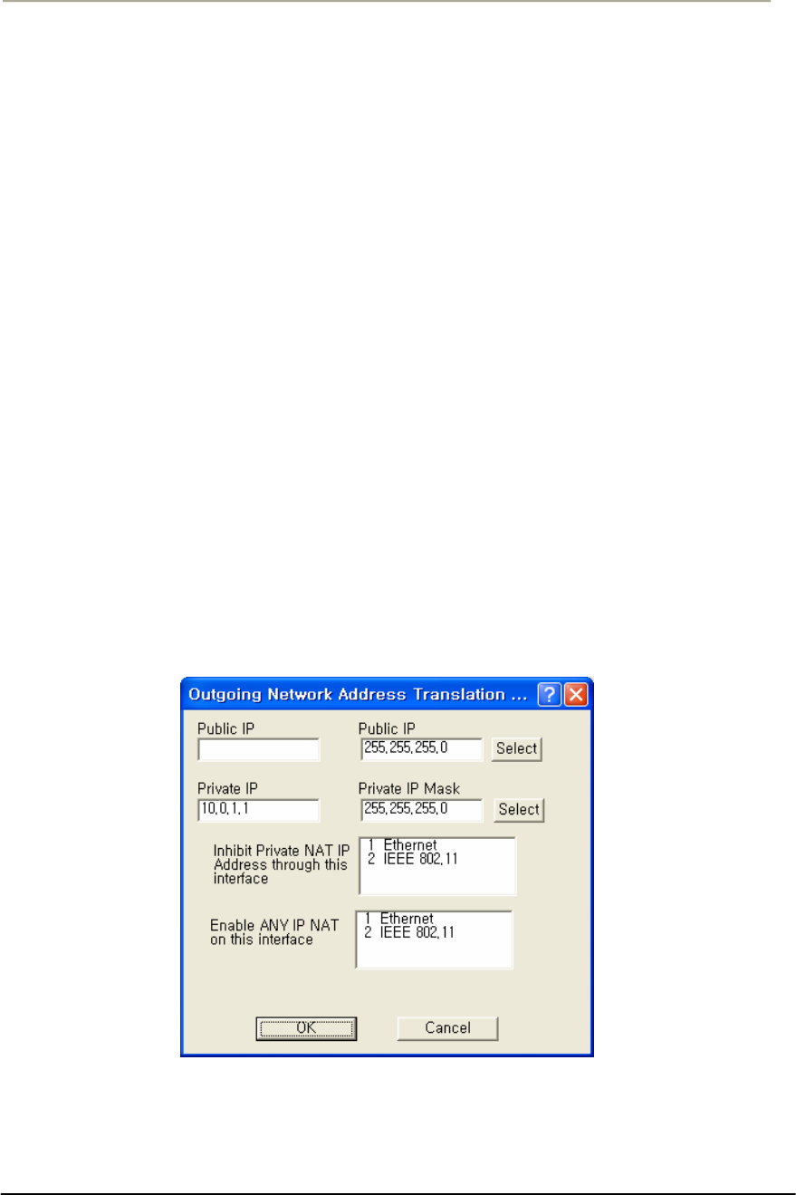
161
Access Point Unit: 2.4G-B-Radio-POE NTPM99AE 01 Rel 1.0 Issue1 May 2007
Set Up Outgoing Network Address Translation (NAT)
Outgoing Network Address Translation (NAT) allows multiple
computers to share a single IP address to connect to an IP network,
including the Internet. This allows homes, small businesses, and Internet
Service Providers to have Internet service for all of their computers
without having to pay for additional IP addresses. The NAT feature
serves as a simple firewall for incoming connections, since only traffic
initiated by an interior computer is permitted through the NAT.
In the screen shown below, when the client 10.0.1.1 wants to send data to
the Internet, the access point will take the packet, replace the return
address of 10.0.1.1 with 140.254.5.147, and then send the packet to the
Internet. When a response comes from the Internet, the access point
sends it to the correct client in the local address space.
Note: This screen is only available when the Enable Outgoing NAT
checkbox has been selected on the General Setup screen.
Note: You do not need to turn on Outgoing NAT if you are using
Incoming NAT, and vice versa. Incoming NAT only needs to be
configured if servers in the local (private) address space need to connect
with clients in the global (public) address space.
Figure 3-72 Outgoing NAT Setup window
Public IP Address-- The IP address/mask seen by the external network.
Note: The IP address and subnet mask must be the same as the one in the
IP Setup dialog under the Setup menu.

162
Access Point Unit: 2.4G-B-Radio-POE NTPM99AE 01 Rel 1.0 Issue1 May 2007
Public IP Mask-- The IP mask seen by the external network.
Note: The IP address and subnet mask must be the same as the one in the
IP Setup dialog under the Setup menu.
Select IP Mask Button-- Clicking this button displays the IP Mask List,
which the shows the IP Masks that can be used as public or private IP
masks for outgoing NAT. The list consists of all possible subnet masks,
and represents the range of addresses that will be translated.
Private IP Address-- The IP address that is seen by the local/internal
network.
Note: The IP will be combined with the subnet mask, and the range of
addresses that results will be translated. This range of IP set must match
the addresses of the clients that connect to the base station.
Private IP Mask-- The IP mask that is seen by the local/internal network.
Note: The IP will be combined with the subnet mask, and the range of
addresses that results will be translated. This range of IP set must match
the addresses of the clients that connect to the base station.
Inhibit Private NAT IP Address through this interface
This option allows you to select one or more interfaces in which NAT
will not be permitted. By default, no interfaces are selected. To select
more than one interface, hold down the <Ctrl> key and click the names
of the interfaces you wish to inhibit. Typically, you will inhibit the
public interfaces because you will generally have users behind the
private side (i.e., the private side is NATed to the public side).
Therefore, you must inhibit the interface used on the public side,
whichever it may be. For example, in the screen shown below, the
Ethernet 10.* network is NATed to the 140.* public wireless network.
Therefore, NAT must be inhibited on the public interface, in this case the
802.11 interface. To do this, you would select 802.11 from the list, and
click the OK button.
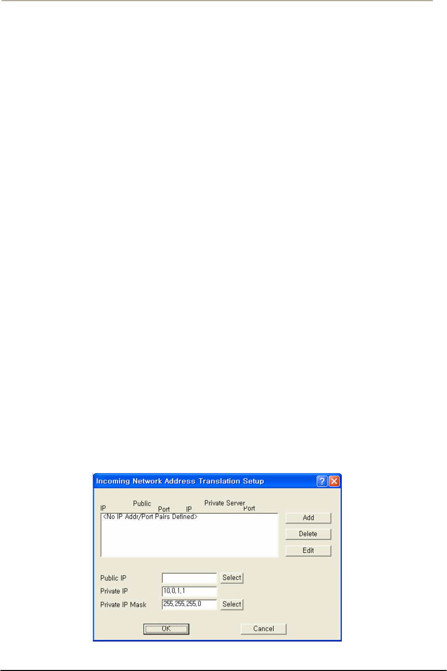
163
Access Point Unit: 2.4G-B-Radio-POE NTPM99AE 01 Rel 1.0 Issue1 May 2007
Set Up Incoming Network Address Translation (NAT)
Incoming Network Address Translations (NAT) is used to redirect
requests to servers in the local address space based on the port of the
request. If, for example, the client at local address 10.0.1.2 is serving
web pages, and a request comes to the access point on that port for a web
session, then the request will be forwarded to the web server on 10.0.1.2.
The server will respond with the web page to the address of the original
request.
Note: This screen is only available when the Enable Incoming NAT
checkbox has been selected on the General Setup screen.
Note: Incoming NAT only needs to be configured if servers in the local
(private) address space need to connect with clients in the global (public)
address space. You do not need to turn on Incoming NAT if you are
using Outgoing NAT, and vice versa.
To set up incoming NAT:
1. From the Setup tab, select General Setup. The General Setup screen
is displayed.
2. Make sure that the Enable IP Routing checkbox is unchecked.
3. Select the Enable Incoming Network Address Translation checkbox,
and then click OK to close the General Setup screen.
4. Click the Incoming NAT button on the Setup tab. The Incoming
Network Address Translation Setup screen is displayed, and any
public and private IP address/port pairs that you have previously
defined are displayed in the window.
Figure 3-73 Incoming NAT Setup window
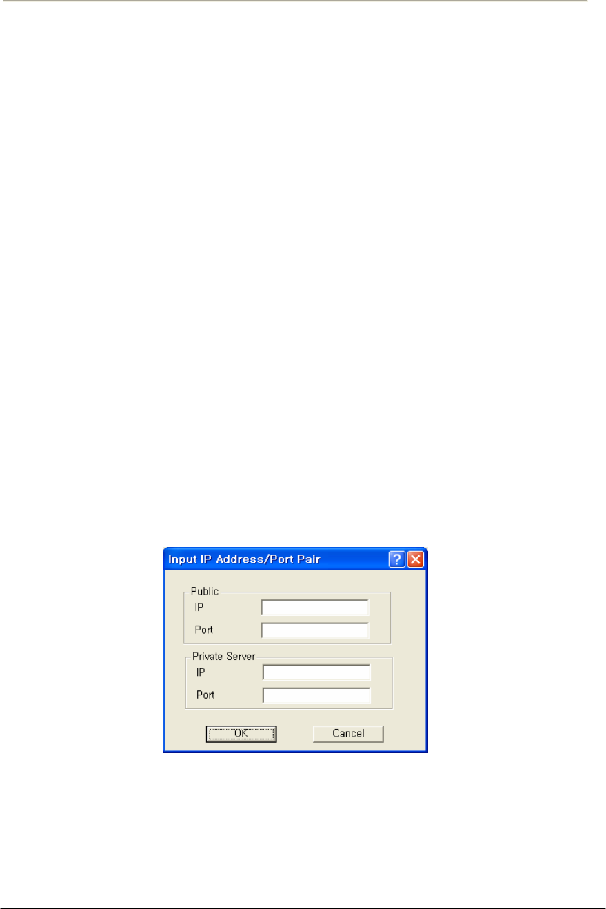
164
Access Point Unit: 2.4G-B-Radio-POE NTPM99AE 01 Rel 1.0 Issue1 May 2007
IP Addresses/Ports-- This window displays the public and private IP
address/port pairs that you have previously defined.
Public IP Mask-- The public subnet mask for your local (internal)
servers in the dialog. The public IP mask is paired with the Public IP
address on the Input IP Address screen, as shown in the screens below.
Note: The public IP Mask must be the same subnet mask that was used
in the setup of the external (or global) address of the base station.
Private IP Address-- The private IP address for your local (internal)
servers in the dialog.
Note: The Private IP Address must be the same as the address and subnet
mask that was selected for your internal network.
Private IP Mask-- The private subnet mask for your local (internal)
servers in the dialog.
Note: The private IP Mask must be the same as the subnet mask that was
selected for your internal network.
Add IP Address/Port Pairs-- Clicking the Add button displays the Add
IP Address/Port Pair screen is used to add new pairs of incoming ports,
and the IP address to which they should be directed.
Figure 3-74 Input IP address/Port (NAT) Setup window
Public IP Address-- The public IP address for the service you wish to
use. On the incoming NAT, there can only be one public address. You
can map ports to specific local servers, but you must use the same public
IP address, as configured on the incoming NAT screen.

165
Access Point Unit: 2.4G-B-Radio-POE NTPM99AE 01 Rel 1.0 Issue1 May 2007
Note: The Public IP address is paired with the Public IP mask on the
Incoming Network Address Setup screen, as shown in the screenshots
below.
Public Port-- The public port for the service you wish to use. For a
discussion of the ports on which well known services run, see
http://www.tatanka.com/doc/technote/tn0081.htm.
Note: The public IP address must be the same for different local servers,
but the port will be different (e.g. different ports for SMTP, FTP, web
servers, etc.).
Private Server IP Address-- The local (private) IP address of the server
to which the request should be forwarded.
Private Server Port-- The local (private) port on the server to which the
request should be forwarded.
Set up IP/UDP/TCP Filters-- Select the Firewall option from the Setup
Tab to set up the IP TCP/UDP firewall (filtering) features.
IP Firewalls are used to restrict access between (sub) networks to certain
IP hosts, types of IP packets, or connections to certain ports. You can set
up the firewall to completely block all external IP traffic, or restrict
access to certain machines, ports, or packet types.
Note: You must select the Enable IP/TCP/UDP Security Filters
checkbox on the General Setup screen in order to access this screen.
Remote IP Address and Mask-- This column of the TCP/UDP Filter
List displays the IP Address and Subnet Mask of the (un-trusted) remote
sub network or machine for which you have chosen to set up this IP
UDP/TCP filter.
Local IP Address and Mask-- This column of the TCP/UDP Filter List
displays the IP Address and Subnet Mask of the local sub network or
machine that is being protected by this particular firewall filter.
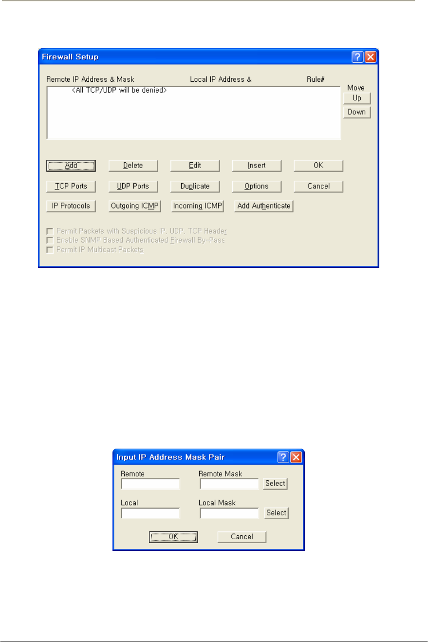
166
Access Point Unit: 2.4G-B-Radio-POE NTPM99AE 01 Rel 1.0 Issue1 May 2007
Figure 3-75 Firewall Setup window
Add/Edit IP Address Mask Pair
The Add/Edit IP Address Mask Pair screen is used to enter both the IP
Address and Subnet Mask of both the local network (or machine) you
would like to protect and the remote network (or host) you would like to
protect it from.
A particular filter is applied only to traffic between the specific local and
remote networks (or hosts) shown in the list. If you wish to filter all
traffic, set the Remote IP Address and Subnet Mask both to '0.0.0.0'.
Figure 3-76 Input IP address (Firewall) Setup window
TCP Security Filters
To set the TCP ports to which a given filter will be applied, select the
filter you want to modify in the TCP/UDP Filter List and click the TCP
Ports button.
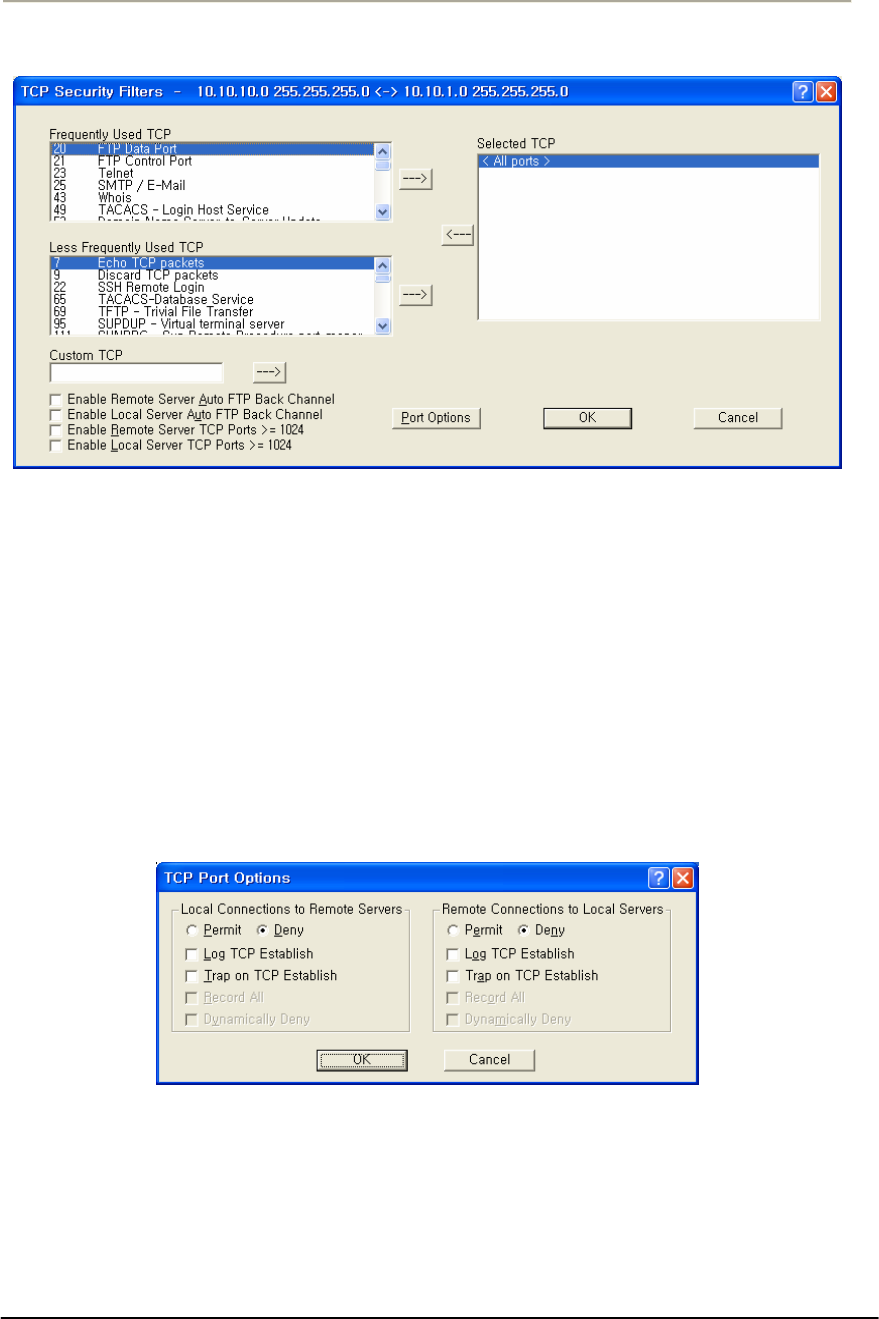
167
Access Point Unit: 2.4G-B-Radio-POE NTPM99AE 01 Rel 1.0 Issue1 May 2007
Figure 3-77 TCP Security Filter Setup window
TCP Port Options
Clicking the Port Options button on the TCP Security Filter screen
displays the TCP Port Options screen. To set how the firewall filter is
applied for a given port, select the port (or the line labeled 'All other
ports') from the Selected TCP Ports list, and click on the 'Port Options'
button. This will display the window below, which you can click on for
more information. If you select the line 'All Other Ports' and then click
the 'Port Options' button, you will see a screen similar to the one
described in the UDP Port Options screen.
Figure 3-78 TCP Port Options Setup window
UDP Port Filters
To set the UDP ports to which a given filter will be applied, select the
filter you want to modify in the TCP/UDP Filter List and click the 'UDP
Ports' button.
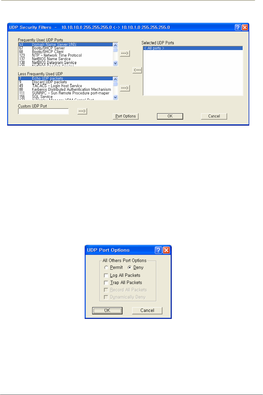
168
Access Point Unit: 2.4G-B-Radio-POE NTPM99AE 01 Rel 1.0 Issue1 May 2007
Figure 3-79 UDP Port Options Setup window
UDP Port Options
Clicking the Portion Options button on the UDP Security Filters screen
displays the UDP Port Options screen. To set how the firewall filter is
applied for a given port, select the port (or the line labeled 'All other
ports') from the Selected UDP Ports list, and click on the 'Port Options'
button. The window displayed below is for the 'All Other Ports' line,
which sets the filter settings for all ports not explicitly listed in the
Selected UDP Ports list. See TCP Port Options for an example using a
specific port.
Figure 3-80 UDP Port Options Setup window
Firewall Setup Options
The Firewall Setup Options screen allows you to set handling options for
a particular filter. Select the filter from the list on the Firewall Setup
screen, and then click the Options button to display the following options.
Alternately, you can simply double click the filter in the list to display
the Firewall Setup Options screen.
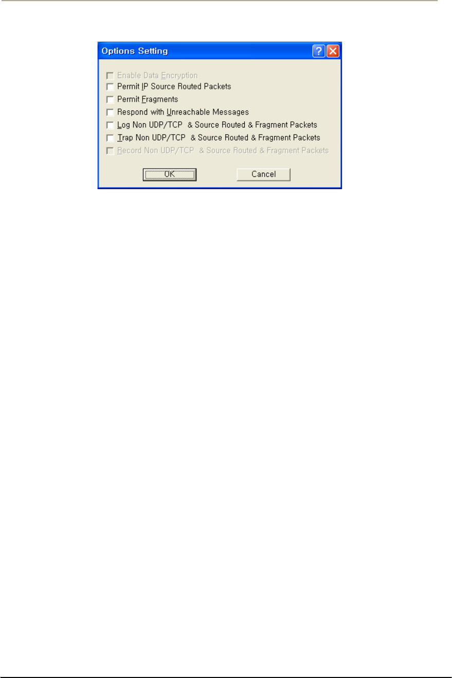
169
Access Point Unit: 2.4G-B-Radio-POE NTPM99AE 01 Rel 1.0 Issue1 May 2007
Figure 3-81 Firewall Option Setup window
Enable Data Encryption-- Select this option if you wish to enable the
data in packets sent between the IP hosts or subnets specified in this filter
to be encrypted/decrypted by the Secure Data Mode Station. This option
is not available if Data Encryption is not enabled on the General Setup
screen.
Permit Non UDP/TCP Packets-- Select this option if you would like
the Secure Data Mode Station to allow IP packets that are neither TCP
nor UDP, such as ICMP. The firewall does not have specific filters for IP
protocols other than TCP, UDP, and ICMP. If you want to deny other
relatively rare protocols, do not select this checkbox.
Permit IP Source Routed Packets-- Select this option if you want the
Secure Data Mode Station to allow Source-Routed IP packets to the local
hosts protected by this filter. Source-Routed packets contain routing
information inside the packet headers, instead of allowing network
routers to decide the best route for the packet. They are primarily used in
network troubleshooting, but may be used to 'fool' the firewall that the
packets are coming from a trusted host. We strongly recommend that you
do not permit source routed packets.
Permit Fragments-- Select this option if you would like the Secure Data
Mode Station to permit fragmented IP packets to be passed through the
firewall. IP packets may be incorrectly fragmented, creating security
problems for hosts that may not properly handle incorrectly fragmented
IP packets.
Respond with Unreachable Messages-- Select this option if you want
the Secure Data Mode Station to respond to remote hosts attempting to
connect to local machines with Destination Unreachable messages when
the connection is denied by this security filter.
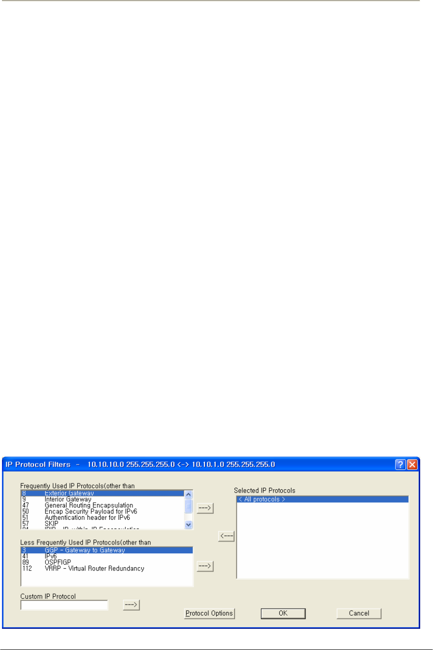
170
Access Point Unit: 2.4G-B-Radio-POE NTPM99AE 01 Rel 1.0 Issue1 May 2007
Log Non UDP/TCP & Source Routed & Fragment Packets-- Select
this option if you want to log to the syslog for all packets that are not
UDP/TCP, are source-routed, or are fragmented.
Trap Non UDP/TCP & Source Routed & Fragment Packets-- Select
this option if you want the Secure Data Mode Station to SNMP Trap
messages whenever a non-TCP or non-UDP, Source Routed, or
Fragmented IP packet is received by the Secure Data Mode Station.
SNMP Traps are sent to the SNMP Trap Host specified in SNMP Setup.
Record Non UDP/TCP & Source Routed & Fragment Packets--
Select this option if you want the Secure Data Mode Station to record all
packets that are not UDP/TCP, are source-routed, or are fragmented.
IP Protocol Filters
Clicking the IP Protocols button displays the IP Protocol Filters screen,
which allows you to set the IP protocols to which a given filter will be
applied. Select the filter you want to modify on the Firewall Setup
screen, and click the IP Protocols button.
Less Frequently Used IP Protocols-- This list displays some of the less
commonly used protocols that run over IP If you wish to filter one of
these protocols, select it and click the [ -> ] button. Then set the action
to take using the Protocol Options button.
Selected IP Protocols-- Select one of the protocols added to the list and
then click the Protocol Options button to set the action for this protocol.
Select “All Protocols" or "All Other Protocols" to set a default action
when a packet is received from a protocol for which no action has been
defined.
Figure 3-82 IP Protocol Filter Setup window
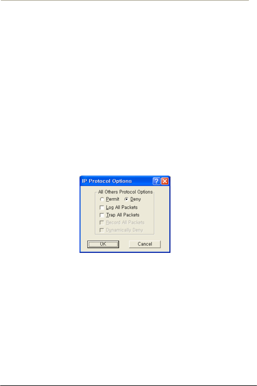
171
Access Point Unit: 2.4G-B-Radio-POE NTPM99AE 01 Rel 1.0 Issue1 May 2007
Custom IP Protocol-- If you wish to explicitly allow or deny access to a
given IP protocol not listed in the two panels above, you can add that
protocol to the list by simply typing it in the Custom IP Protocol field
and clicking on the right arrow button [->] next to the text field. You do
not need to add a protocol to the list unless you have specific
requirements for that particular protocol.
IP Protocol Options
Clicking the Protocol Options button displays the IP Protocol Options
screen, which allows you to define an action to take when data using that
protocol is sent or received. When you select a protocol to filter, you
will need to define an action to take when data using that protocol is sent
or received. Initially, you will need to indicate whether you wish to
permit or deny that protocol. In addition, you can optionally choose to
log, trap, or record all packets, and to dynamically deny all other
protocols.
Figure 3-83 IP Protocol Option Setup window
Permit All Other Protocols Button-- Select this button if you wish to
permit all other protocols.
Deny All Other Protocols Button-- Select this button if you wish to
deny all other protocols.
Log All Packets-- Select this checkbox if you wish to log all packets.
Trap All Packets-- Select this checkbox if you wish to trap all packets.
Record All Packets-- Select this checkbox if you wish to record all
packets.
Dynamically Deny All Other Protocols-- Select this checkbox if you
wish to dynamically deny all other protocols.
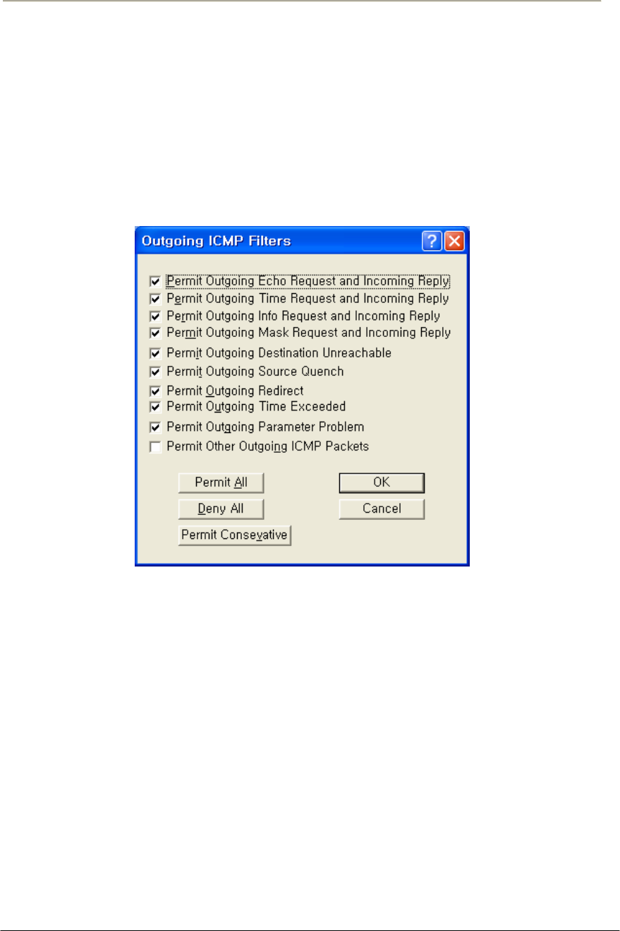
172
Access Point Unit: 2.4G-B-Radio-POE NTPM99AE 01 Rel 1.0 Issue1 May 2007
Outgoing ICMP Filters
Clicking on the Outgoing ICMP button on the Firewall Setup screen
displays the Outgoing ICMP Filters screen, which allows you to permit
or deny ICMP packets from going out from the local to remote interfaces.
This allows you to deny diagnostic messages requested by internal
(private) sources in this filter from being sent to external (un-trusted)
machines.
Figure 3-84 Outgoing ICMP Filter Setup window
Permit Outgoing Echo Request and Incoming Reply-- Permit Echo
(ping) Requests sent from local stations to remote stations, and the
remote stations' replies.
Permit Outgoing Time Request and Incoming Reply-- Permit local
stations' Time Requests sent to remote stations and the replies from
remote machines.
Permit Outgoing Info Request and Incoming Reply-- Permit local
stations' Information Request packets sent to remote stations, and the
remote stations' replies.
Permit Outgoing Mask Request and Incoming Reply-- Permit local
stations' Mask Request packets sent to remote stations, and the remote
stations' replies.

173
Access Point Unit: 2.4G-B-Radio-POE NTPM99AE 01 Rel 1.0 Issue1 May 2007
Permit Outgoing Destination Unreachable-- Permit Destination
Unreachable packets generated on the (private) local network to be sent
to external machines
Permit Outgoing Source Quench-- Permit Source Quench messages
generated by gateways on the local network to be sent to remote
machines sending packets to that gateway.
Permit Outgoing Redirect-- Permit Redirect messages generated by
gateways on the local network to be sent to remote machines sending
packets to that gateway.
Permit Outgoing Time Exceeded-- Permit Time Exceeded messages
generated by gateways on the local network to be sent to remote
machines sending packets to that gateway.
Permit Outgoing Parameter Problem-- Permit the local network to
send Parameter Problem messages to the remote network when there was
a problem with the header parameters of a packet.
Permit Other Outgoing ICMP Packets-- Permit other ICMP packets
not listed above to be sent from the local network to the remote network.
Permit All Button-- Clicking this button selects all checkboxes on the
Outgoing ICMP Filters screen.
Deny All Button-- Clicking this button de-selects (un-checks) all
checkboxes on the Outgoing ICMP Filters screen.
Permit Conservative Button-- Clicking this button automatically
selects all checkboxes on the Outgoing ICMP Filters screen except for
the Permit Other Outgoing ICMP Packets checkbox.
Incoming ICMP Filters
Clicking on the Incoming ICMP button on the Firewall Setup screen
displays the Incoming ICMP Filter screen, which allows you to permit or
deny ICMP packets from coming in from 'remote' to 'local' interfaces.
This allows you to deny diagnostic messages requested from external
(un-trusted) sources in this filter from being sent to your local (private)
machines.
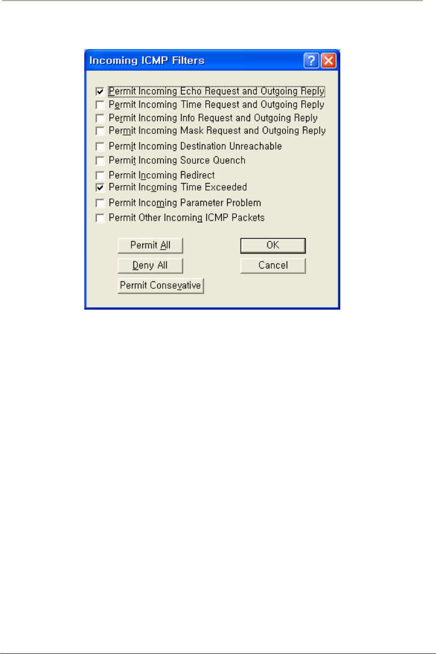
174
Access Point Unit: 2.4G-B-Radio-POE NTPM99AE 01 Rel 1.0 Issue1 May 2007
Figure 3-85 Incoming ICMP Filter Setup window
Permit Incoming Echo Request and Outgoing Reply-- Permit Echo
Requests sent from remote (un-trusted) computers to be sent to machines
on the local (private) network, and allow the local machine to reply to
them.
Permit Incoming Time Request and Outgoing Reply-- Permit
Timestamp Requests sent from remote (un-trusted) computers to be sent
to machines on the local (private) network, and allow the local machine
to reply to them.
Permit Incoming Info Request and Outgoing Reply-- Permit
Information Request packets sent from remote (un-trusted) computers to
be sent to machines on the local (private) network, and allow the local
machine to reply to them.
Permit Incoming Mask Request and Outgoing Reply-- Permit Mask
Request packets sent from remote (un-trusted) computers to be sent to
machines on the local (private) network, and allow the local machine to
reply to them.
Permit Incoming Destination Unreachable-- Permit Destination
Unreachable messages generated by remote computers to be sent to
machines on the local network.

175
Access Point Unit: 2.4G-B-Radio-POE NTPM99AE 01 Rel 1.0 Issue1 May 2007
Permit Incoming Source Quench-- Permit Source Quench packets
generated by gateways on the remote network to be sent to gateways on
the local network.
Permit Incoming Redirect-- Permit ICMP Redirect packets generated
by gateways on the remote network to be sent to machines on the local
network.
Permit Incoming Time Exceeded-- Permit Time Exceeded messages
generated by machines on the remote network to be sent to machines on
the local network.
Permit Incoming Parameter Problem-- Permit Parameter Problem
messages generated by machines on the remote network to be sent to
machines on the local network.
Permit Other Incoming ICMP Packets-- Permit other ICMP packets
not listed above to be sent from the (un-trusted) remote network to the
(private) local network.
Permit All Button-- Clicking this button automatically selects all
checkboxes on the Incoming ICMP Filters screen.
Deny All Button-- Clicking this button automatically de-selects (un-
checks) all checkboxes on the Incoming ICMP Filters screen.
Permit Conservative Button-- Clicking this button automatically
selects the following checkboxes on the Incoming ICMP Filters screen:
Permit Incoming Echo Request and Outgoing Reply
Permit Incoming Destination Unreachable
All other checkboxes are automatically de-selected (unchecked).
Add Authentication Record
The Add Authentication Record screen is used to add an SNMP-based
username/password firewall authentication bypass class. The
Authentication class works much like a UNIX user group does; you can
specify what types of packets a person in this authentication class can
pass through the firewall when logged in with the approved username
and password.
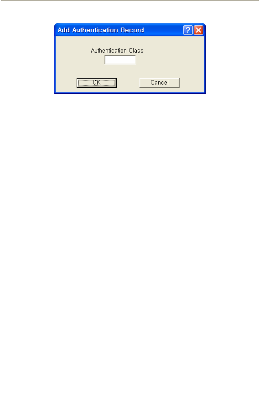
176
Access Point Unit: 2.4G-B-Radio-POE NTPM99AE 01 Rel 1.0 Issue1 May 2007
Figure 3-86 SNMP Authentication Record Setup window
Authentication Class Number-- Enter a number for an SNMP-based
username/password firewall authentication bypass class. The
Authentication class works much like a UNIX user group does; you can
specify what types of packets a person in this authentication class can
pass through the firewall when logged in with the approved username
and password.

177
Access Point Unit: 2.4G-B-Radio-POE NTPM99AE 01 Rel 1.0 Issue1 May 2007
Administration
The WLAN Cable Access Point 6220 CSU has the following
management and operational features listed below:
Saving Configuration
Loading new Configuration
Uploading Software
Rebooting the remote station
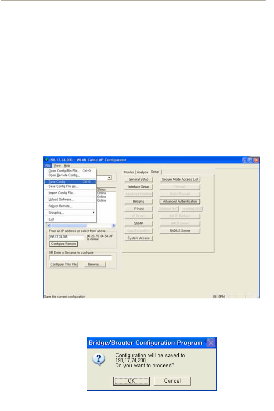
178
Access Point Unit: 2.4G-B-Radio-POE NTPM99AE 01 Rel 1.0 Issue1 May 2007
Saving configuration
Saving the current configuration settings to the hardware device is a one-
step process:
Use this File Menu option to save the base station configuration
parameters to the location from which they were read. If the
configuration was read from a base station, it will be saved to the CSU
from which it was read. If the configuration was read from a file, the
modified configuration will be saved back to that file.
To import a saved configuration to an CSU, first connect to the base
station using Open Remote Config, then use Import Config File.
1. From the File Menu, select Save Config.
Figure 4-1 Save Config Menu
2. Click on the ‘Yes’ button
Figure 4-2 Confirm Save Config Window
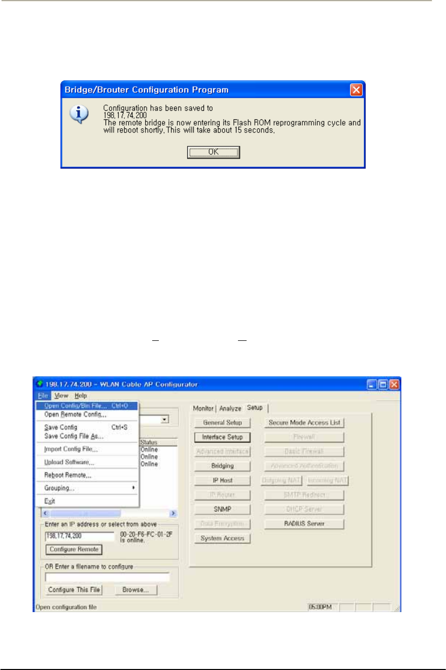
179
Access Point Unit: 2.4G-B-Radio-POE NTPM99AE 01 Rel 1.0 Issue1 May 2007
3. The message box will be displayed, as shown below, and then left
click on the OK button.
Figure 4-3 Reboot Message Dialog Box
4. Just after this saving, APU or CSU will be restarting automatically.
Loading new configuration
The 'import config file' option enables you to 'copy' the parameter values
that you entered to configure the first Secure Data Mode Station to the other
units. The “import config file” option enables you to 'copy' the parameter
values that you entered to configure the first Secure Data Mode Station to
the other units.
1. From the File menu, select Open/Config Bin File.
Figure 4-4 Open Config/Bin File Menu
2. And the browse window will appear.
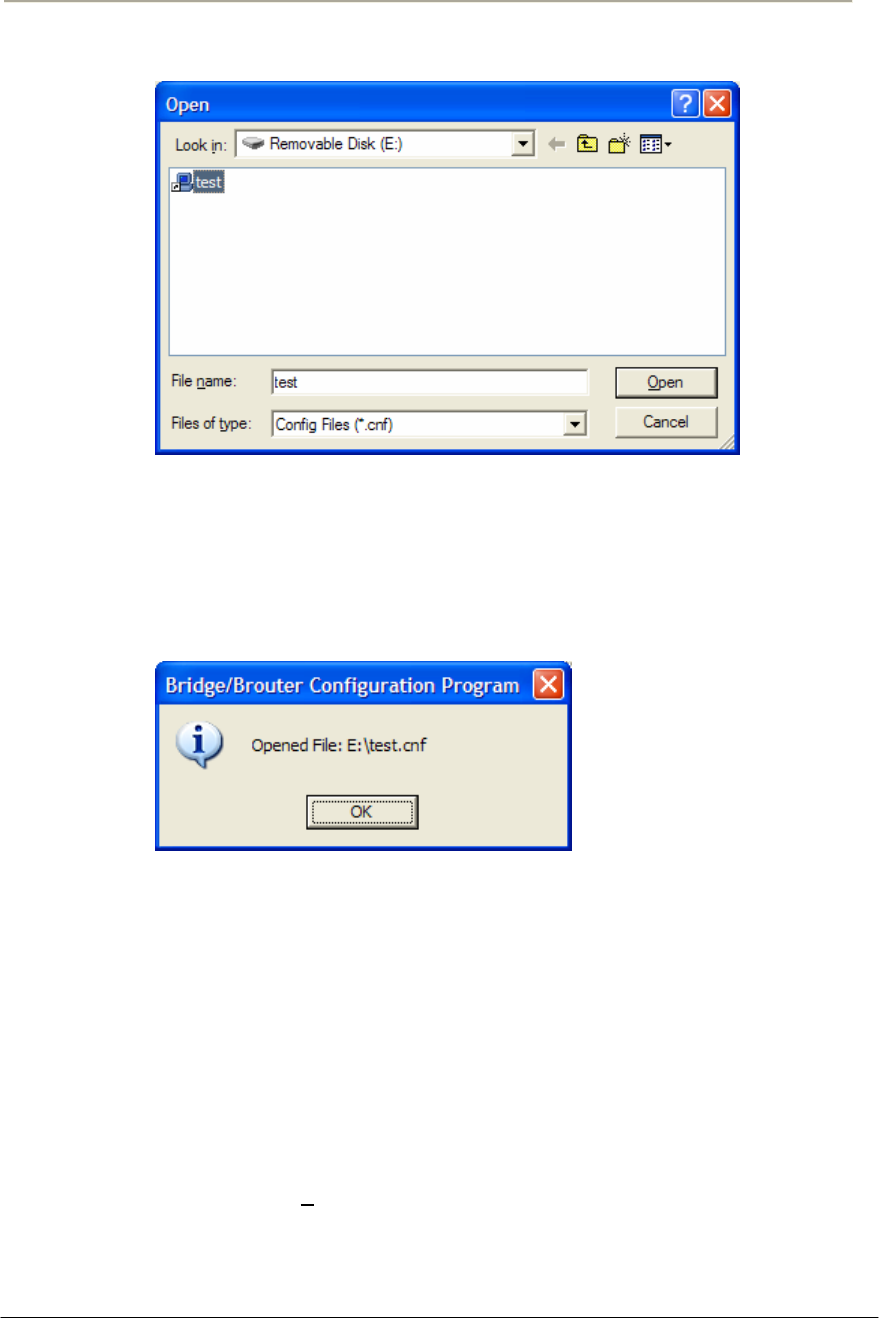
180
Access Point Unit: 2.4G-B-Radio-POE NTPM99AE 01 Rel 1.0 Issue1 May 2007
Figure 4-5 Open Config File Window
3. Select the configuration file in the specific folder, and Click
‘Open’ button,
4. Then, bridge/brouter Configuration Program” screen will appear.
Figure 4-6 Confirm Open Config File Dialog Box
5. Left click on the OK button.
Uploading Software
There are ten steps that must be done to import the .bin file and its
corresponding license file. Be sure you have downloaded and know the
location of your files before you start.
1. From the File menu, select Open Config/Bin File, and the browse
window will appear.
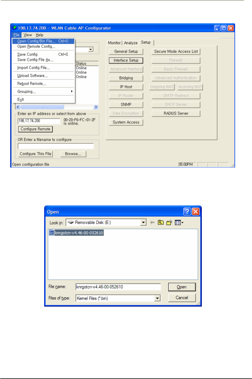
181
Access Point Unit: 2.4G-B-Radio-POE NTPM99AE 01 Rel 1.0 Issue1 May 2007
Figure 4-7 Upload Software Menu
2. Browse to the location of your .bin file, and select it.
Figure 4-8 Open binary Window
3. Click on the ‘Open’ button, and the "License Key Setup" screen
will appear:
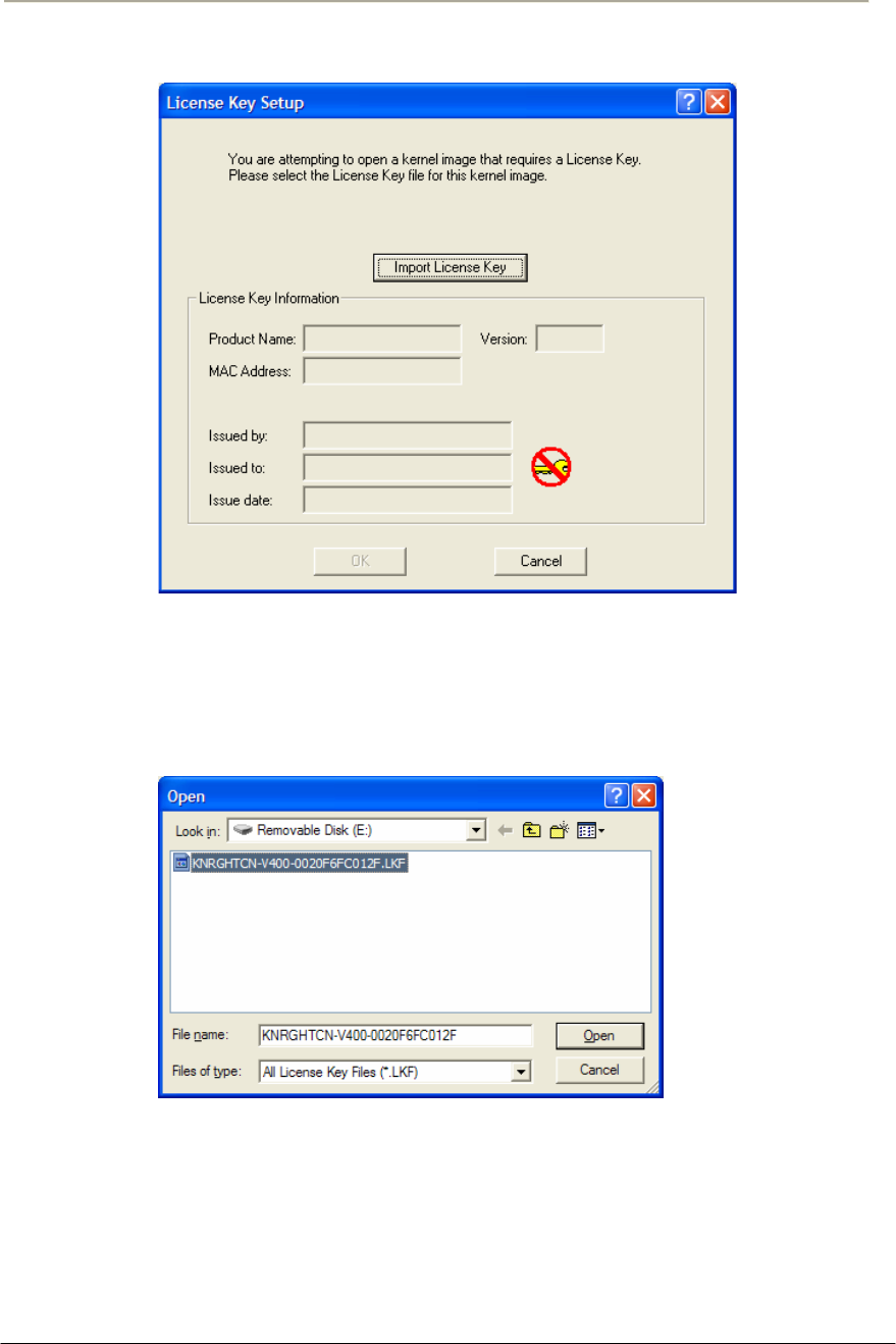
182
Access Point Unit: 2.4G-B-Radio-POE NTPM99AE 01 Rel 1.0 Issue1 May 2007
Figure 4-9 License Key Setup Window
4. Click on the "Import License Key" button, and an "Open" dialog
box will appear:
Figure 4-10 Open License Key Window
5. Select the license file that corresponds to the Ethernet MAC of the
unit you are working with. (If you have "Licenses for this MAC
address" selected in the file type drop box, only the licenses for the
MAC of the current unit will appear.
6. Click on the ‘Open’ button
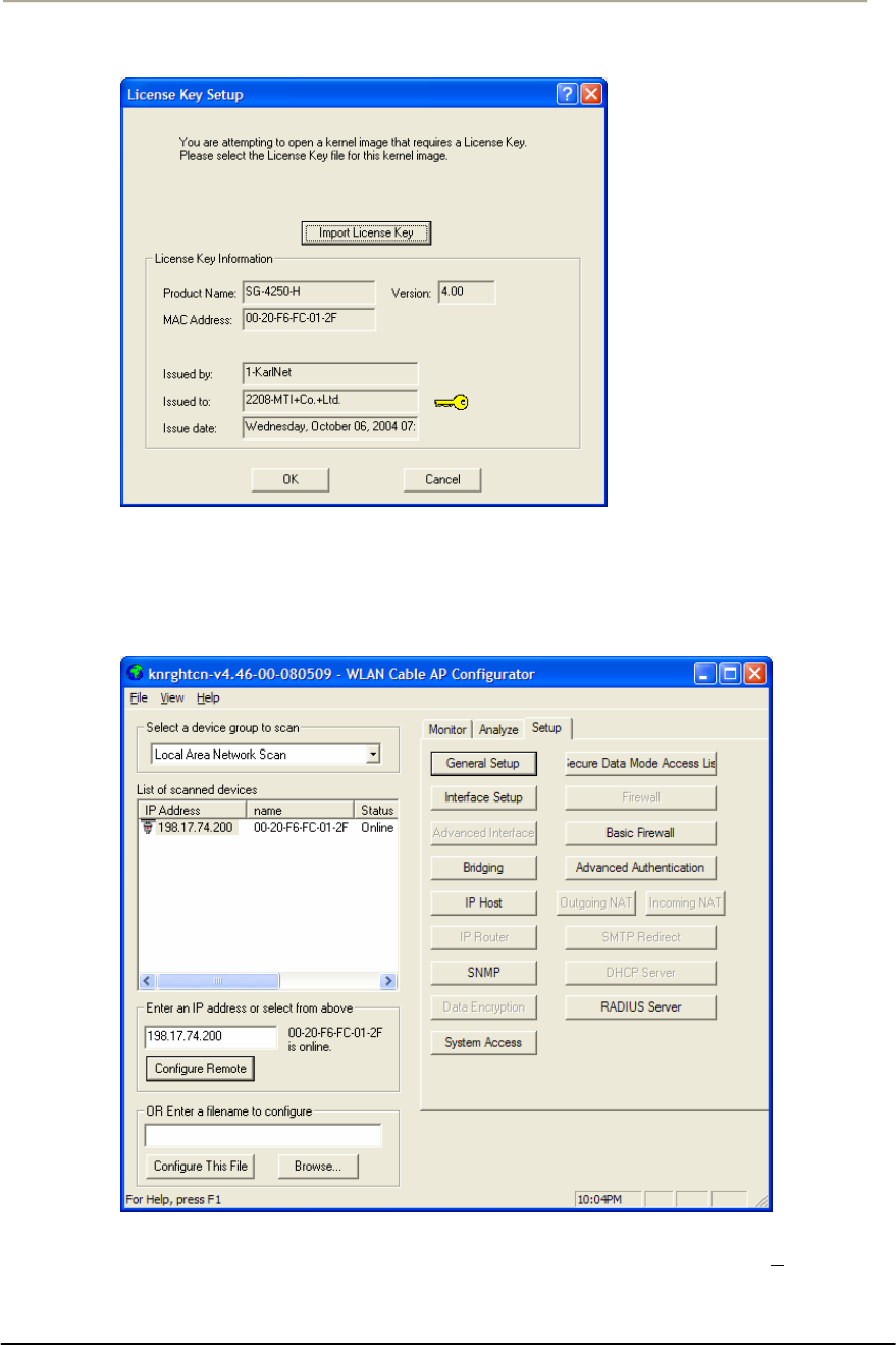
183
Access Point Unit: 2.4G-B-Radio-POE NTPM99AE 01 Rel 1.0 Issue1 May 2007
Figure 4-11 License key setup window
7. Click on the ‘OK’ button
Figure 4-12 Setup window
8. You can see an initial setup windows and then, From the File
menu, select upload software as below.
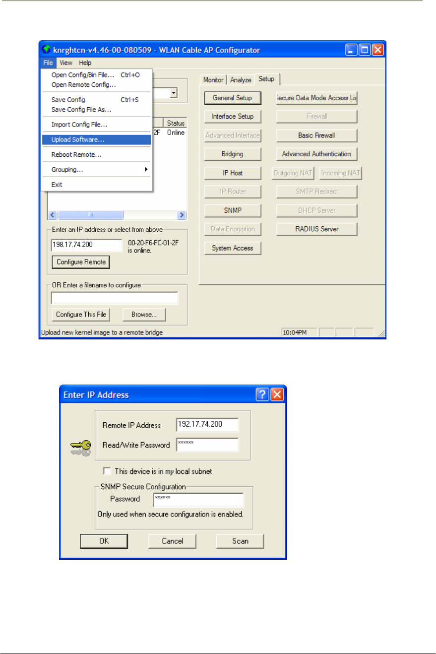
184
Access Point Unit: 2.4G-B-Radio-POE NTPM99AE 01 Rel 1.0 Issue1 May 2007
Figure 4-13 Selecting Upload Software
Figure 4-14 Enter IP address dialog
9. Enter the IP address of the unit to upload new software binary and
Click on the ‘OK’ button.
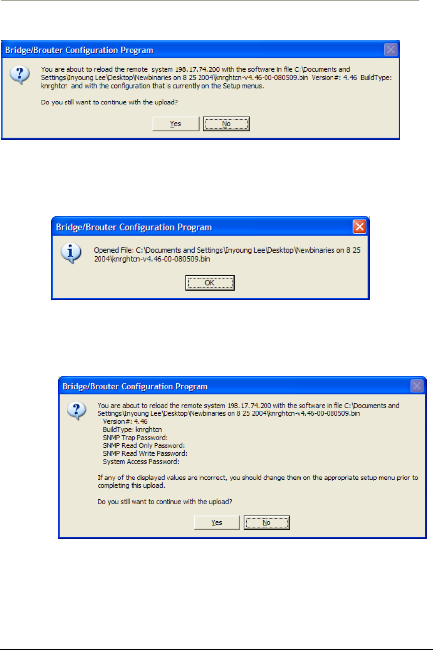
185
Access Point Unit: 2.4G-B-Radio-POE NTPM99AE 01 Rel 1.0 Issue1 May 2007
Figure 4-15 Uploading Confirmation Dialog 1
10. Click on the ‘OK’ button
Figure 4-16 Uploading Confirmation Dialog 2
11. Click on the ‘OK’ button
Figure 4-17 Uploading Binary Information Dialog Box
12. Click on the ‘OK’ button
13. “Saving ….Please be patient” screen will appear as below
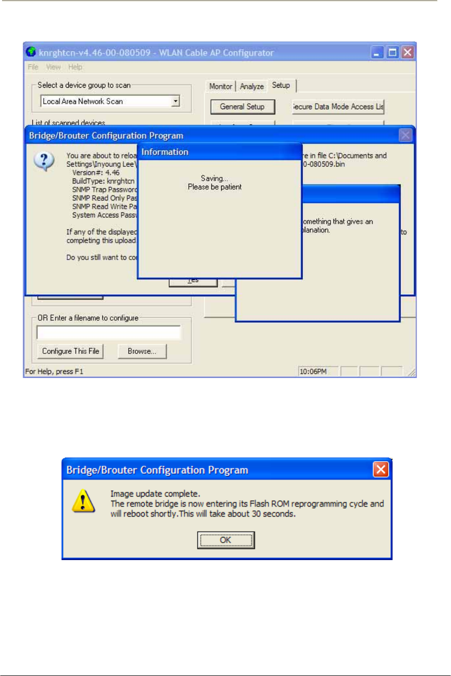
186
Access Point Unit: 2.4G-B-Radio-POE NTPM99AE 01 Rel 1.0 Issue1 May 2007
Figure 4-18 Saving software uploading window
14. Click on the ‘OK’ button
Figure 4-19 Reboot Message Dialog Box
15. Click on the ‘OK’ button
16. Software Uploading complete.

187
Access Point Unit: 2.4G-B-Radio-POE NTPM99AE 01 Rel 1.0 Issue1 May 2007
Reboot a Remote Station(APU and CSU)
The Reboot Remote option of the file menu allows you to reboot remote
devices if stations get dropped from the network.
Please follow the rebooting procedure to reboot a station from a remote
location.
1. Select File/Open Remote Config.
2. Enter the IP address and read/write password for the target base
station.
3. Once the configuration has been read from bridge, select
File/Reboot Remote.
4. The APU or CSU will restart and run startup diagnostics.
Note: After approximately 60 seconds, the unit will start bridging operation
using the configuration parameters as they were stored in the remote station
prior to the Reboot.
Note: If you would like to display the configuration file or monitor the
unit's performance after a Reboot, you may have to wait until the unit
completes the start-up diagnostics. Once the startup diagnostics are
complete, the unit can be accessed again.

188
Access Point Unit: 2.4G-B-Radio-POE NTPM99AE 01 Rel 1.0 Issue1 May 2007
Troubleshooting

189
Access Point Unit: 2.4G-B-Radio-POE NTPM99AE 01 Rel 1.0 Issue1 May 2007
1. How do I see and configure a setup parameter of the CSU without a radio
connection to the APU?
The only devices that will display in the Configurator local scan window are the
units in the same subnet as your management computer. If the device in question
is not displayed in your local scan window, change the IP address (Client PC) to
any one of the subnet IP address groups “198.17.74.XXX” and then, you can
find out the CSU entity with the IP address “198.17.74.254”.
2. Why can CSU setup a radio connection to the APU?
Such situations are caused by various reasons as below:
- Mismatching between the radio setup parameter of APU and that of CSU
+ Radio Configuration (802.11a, 802.11g, 802.11g)
+ Radio Channel
+ Network ID (NWID)
+ WEP Encryption Key
- Radio Link Designing Problem(Link Distance, Antenna Direction and so
on)
3. How many CSU subscribers can connect to a single WLAN Cable Access
Point (APU Secure Data mode)?
In case a set of CSU uses public IP address, the APU associated with them is cap
able of maintaining only 15(fifteen) of link connections because the maximum n
umber of clients which the cable modem can handle is 31(thirty one) in secure d
ata mode.
4. How does the number of CSU affect the wireless throughput between APU
and CSU in Secure Data mode?
As more CSU Secure Data modes are added, the APU Secure Data mode Base
Station mode is still able to effectively manage the throughput of the overall
wireless link. Just as on any shared medium, each station's throughput is
determined by the overall usage of the wireless link. The more stations
transmitting on the link at a time, the lower each individual station's throughput
goes. However, Secure Data mode performs in such a way that up to a point, the
more heavily loaded the network becomes, the higher the overall throughput
becomes.
For example, due to the intricacies of our Adaptive Dynamic Polling algorithms
and Secure Data mode 'fairness' principles, a single-user FTP session does not
use all of the possible wireless bandwidth. But when performing several
different transfers to and from different CSU Secure Data modes, the actual
overall bandwidth of the Secure Data mode network increases. In general, the

190
Access Point Unit: 2.4G-B-Radio-POE NTPM99AE 01 Rel 1.0 Issue1 May 2007
heavier a Secure Data mode network is loaded, the higher the total bandwidth
used becomes.
5. How do I check throughput?
Network throughput can be tested and analyzed using the Ping Fill test. This test
dynamically fills the network connection with ICMP Echo (ping) packets and
waits for the responses from the target station. Since each packet sent is echoed
back to the sender, this tests the overall wireless throughput in both directions.
Choosing the correct parameters is crucial to obtaining accurate Ping Fill test
results. The speed at which the target station responds to the ICMP Echo packets
is crucial to correctly assess the speed of the wireless link.
The IP stacks in some PC operating systems, such as Microsoft Windows, often
do not respond quickly enough to the ICMP Echo packets to obtain an accurate
assessment of your network throughput. When running the Ping Fill test to a
Microsoft Windows system, your results may be slightly lower than normal
throughput.
6. How do I read the configuration from a device if I cannot see the unit in the
local scan window?
The only devices that will display in the Configurator local scan window are the
units in the same subnet as your management computer. For example your PC
has an IP address 64.22.33.13 with a subnet mask of 255.255.255.0 and your
device has an IP address of 65.23.11.2 with a subnet mask of 255.255.0.0. The
device in question would not display in your local scan window.
Even though you may be able to ping the unit it may not be visible in the local
scan window. In the Configurator, select the file menu, and then open remote
configuration and then type in the IP and the password. It may be necessary to
select the "this device is in my local subnet" check box to actually read the
configuration from the unit. Attempt to read the configuration with it un-checked
first. If the configuration cannot be read try with this box checked.
7. It seems to have lost or forgotten the read/write password to manage my
product.
How can I get back in to manage the unit?
If the read/write password has been lost or forgotten, there is only one thing that
can be done about this in order to be able to manage the unit again. The unit
must be put into force reload mode and the firmware must be reloaded. All
configuration settings will be lost. Physical access to the unit is required in order
to accomplish this procedure.
8. I am performing a wireless link test from a CSU Secure Data mode and one
of my CSU Secure Data modes on the other side of my base station is
showing up, is this a problem?

191
Access Point Unit: 2.4G-B-Radio-POE NTPM99AE 01 Rel 1.0 Issue1 May 2007
It is a normal function to be able to see the other units in the wireless link test
this way. This shows you which devices reside in the subnet range or a group of
users so that you can get a table of all secure mode units. To hide each CSU
subscribers, you have to access to APU and enable the check box of “Deny
inter-client traffic on this interface” in the wireless interface setup dialog of AP
configurator. Please see “Setup 802.11” of the related section “Configuration”.
9. Please provide the list of parameters for the different levels of signal
strengths i.e. No Connection, Poor, Acceptable, Good, and Excellent. How
do I determine what is good and bad?
What these values will mean, is somewhat specific to the environment being
worked under. For example, a Signal to Noise Ratio of 15 may be fine for one
area and 15 may not work very well in a high noise area. So here are some
general guidelines. Keep in mind all the information below is related to Secure
Data mode, for 802.11b mode replaces retransmit with dropped packets:
There are some further items to note:
Link planning should be done in your general geographic area and your links
should be set up with an extra margin that your company determines.
Links are best performed when possible with high gain antennas as opposed to
low gain amplified antennas
Noise is typically introduced by failing amplifiers and problems with connectors
and defective radios. Signal typically drops with bad cabling, connectors or
antenna misalignment, radio power issues Network ID and Channel values being
the same, may help stability in marginal links.
Marginal (sporadic links) typically occur in SNR ranges from 5-9, 10-15 usually
will keep association with retransmits or some packet loss. SNR from 16 and up
usually are acceptable for every day operation.
If SNR is over 25 and throughput is poor, overdriving or multi-path may be the
cause of the problems.
Secure Data Mode Station Entries - Provides information on octal packet,
retransmitted packets and failed packets. A value other than 0 under failed
packets typically points to a link issue. Keep in mind TC retransmits a packet 9
times, (with the initial packet 10 total).
This has occurred and the packet has been dropped when a failure occurs.
Retransmits should be 15% or less of total transmits, this may indicate signal,
noise or antenna alignment issues.
Remote Statistics - Check each Ethernet Interface, any errors or collisions may
be signs of link speed or greater network related issues.

192
Access Point Unit: 2.4G-B-Radio-POE NTPM99AE 01 Rel 1.0 Issue1 May 2007
Check each wireless interface. Specifically, compare the Frame Check Sequence
errors to the bytes in values. Typically FCS occurs on any wireless connection.
This should only be a concern if the value exceeds approximately 10% of the
bytes in value. This may be an indicator of signal/multi-path issues.
10. Can I block unwanted MAC addresses from the Ethernet interface?
It is possible to set an Access Control List to set all of your allowable MAC's on
the Ethernet (everything else on the Ethernet will be denied) by reading the
configuration from the unit with the WLAN Cable AP Configurator. Go to the
Setup tab -- General Setup -- Select the Mac Authentication Access control radio
button and click OK. Then select the Setup tab -- Advanced Authentication --
check the Access Control List and then click the Setup button. Add all your
allowable MAC's and select the Ethernet interface to apply the ACL.

193
Access Point Unit: 2.4G-B-Radio-POE NTPM99AE 01 Rel 1.0 Issue1 May 2007
Appendix
A. Specification
B. Antenna
C. Link Engineering
D. Enclosure Dimension

194
Access Point Unit: 2.4G-B-Radio-POE NTPM99AE 01 Rel 1.0 Issue1 May 2007
Appendix A. Specification
Access Point Unit (APU)
Physical
Dimension
z300(W) * 232.6(L) * 112(D) [Unit: mm]
z11.81 (W) * 9.157 (L) * 4.40 (D) [Unit: inch]
Weight(without antenna): 6.661 lbs(<7 lbs), 3.0 Kg
Enclosure: Strong Aluminum alloy case –Steel with anodizing coating
surface(Waterproof, EMI protection, Vibration Robust)
Power consumption: Max 6W(3.3Vdc/1.5A)
System elements: Access Point, POE PD(Power Device)
Interface Ports: Ethernet Port(CAT5/POE/802.3af)
Pole mountable and External Built-in type Antenna
Wireless LAN
Wireless LAN standard: IEEE 802.11b
Frequency Band & Channel
2.4~2.4835GHz(ISM)
Table A.1 802.11b(ISM) channel assignment
Frequency Channel 6 2437 MHz
1 2412 MHz 7 2442 MHz
2 2417 MHz 8 2447 MHz
3 2422 MHz 9 2452 MHz
4 2427 MHz 10 2457 MHz
5 2432 MHz 11 2462 MHz
Modulation: DSSS(DBPSK,DQPSK,CCK)
Data rate: 1Mbps, 2Mbps, 5.5Mbps, 11Mbps
Power adjustment (4 steps): 100%(Max), 50%, 25%, 12.5%
Maximum Transmit Power(Radio)
195
Access Point Unit: 2.4G-B-Radio-POE NTPM99AE 01 Rel 1.0 Issue1 May 2007
Table A.2 Output power table [dBm] in 802.11b
CH 2412 MHz 2447MHz 2462 MHz Remark
1 Mbps 12 12.2 12.3 +/-1.5dB
2 Mbps 11.2 11.4 11.5 +/-1.5dB
5.5 Mbps 10.2 10.4 10.5 +/-1.5dB
11 Mbps 9.7 9.9 10.0 +/-1.5dB
Max EIRP [dBm] for PMP topology
Table A.3 Output power table [dBm] in 802.11b
Mode NTA-2407 NTA-2412 NTA-2400 EIRP Limit
11b 27 22 20 36 dBm(4W)
Receiver sensitivity: (Normal Temperature)
Table A.4 Receiver Sensitivity table (802.11b)
Data Rate Receiver Sensitivity
1 Mbps -83dBm
2 Mbps -86dBm
5.5 Mbps -89dBm
11 Mbps -92dBm
Software
Firmware : APU Secure Data Mode (Base Station)
Wireless Service Protocol : Secure Data Mode, Dynamic Polling
MAC access control – 32 local MAC Address Table (SDM mode)*
Standard RADIUS server support
Wired Equivalent Privacy encryption - 64, 128, AES
Firewall (ICMP/UDP/TCP/IP Protocol Filtering)
Layer 2 Protocol Filtering
BOOTP/DHCP (Server, Relay, Client), Static IP
NAT (Incoming/Outgoing)
Routing Protocol (RIP v2, Static)
Restriction of Broadcast Storm
SNMP v1, Software upgrade via TFTP (only applicable to cable modem)
GUI Program : Windows Based
Throughput Analysis: Ping Fill
Radio Performance Testing Tool: Antenna Alignment
Remote Statistics Monitoring
SNMP Traps
MIB II

196
Access Point Unit: 2.4G-B-Radio-POE NTPM99AE 01 Rel 1.0 Issue1 May 2007
(*) There is a limit of 32 if you use MAC address and comment per entry. However
each APU can support 64 CSU's associating with it in SDM mode if you use only
MAC address per entry. If you use a RADIUS server for this setup, there is no
limitation.
Environmental
Operating Temperature: -40°C to +60°C
Storage Temperature: -40°C to +85°C
Humidity: 5% to 100% non-condensing
Weather Rating: IP67 weather tight
Operating Altitude/Solar Load Test: <3,000 meter above see level
Salt/Fog/Rust Resistance: ASTM B 117 (Tested for 30 days)
Shock & Vibration
zOperation
ETS 300 019-2-4 Class 4.1/4.1E: Subclass 4M3 IEC 68-2-64
ETS 300 019-2-3 reference IEC 68-2-27 Shock tolerance
zTransportation(Non-operating & Shipping)
ETS 300 019-2-4 Class 1.2 (storage)
ETS 300 019-2-4 Class 2.3 (transportation)
Impact: GR-950-CORE section 6.4.7(ASTM D 2444 Tup “B” Nose Detail)
Chemical resistance of nonmetallic components
zCRC226 Water Displacement Lubricant
zWD40 Water Displacement Lubricant
zCable Filling compound, as used in the field
zSplice encapsulating Compound
zIsopropy Alcohol Grade HPLC
z3% H2SO4 (sulphuric acid)
z0.2% NaOH (Sodium Hydroxide)
zWasp & Hornet Spray
Rain resistance
zETS 300 019-1-2 Class 2.3(transportation)
zETS 300 019-1-4 Class 4.1(operating)
Immunity
zRadiated RF/EMV Field (IEC 61000 4-3): 5V/M (5 MHz ~ 1GHz)
zESD(IEC 61000 4-2) : +/- 15kV (air) and +/- 8kV (contact)
zSurge (IEC 61000 4-5) : 6kV Combination Wave (IEEE C62.41)
Certification
Radio / EMC
zFCC CFR47 Part 15, Class B
Safety
zPlenum rated, UL 50, UL 60950-1

197
Access Point Unit: 2.4G-B-Radio-POE NTPM99AE 01 Rel 1.0 Issue1 May 2007
Corporate Service Unit (CSU)
Physical
Dimension
180(W) * 180(L) *81(D) [Unit: mm]
180(W) * 239(L) *81(D) with the EMI cap [Unit: inch]
Weight(without antenna): 2.8659 lbs(1.30 Kg) with the mounting bracket kit
Enclosure: Gray UV Stabilized ASA(Cover), Aluminum and HDG Steel(Body)
Power consumption: Max 6W(3.3Vdc/1.5A)
System elements: Access Point, POE PD(Power Device)
Interface Ports: Ethernet Port(CAT5/POE/802.3af)
Pole mountable and Built-in type Antenna
Wireless LAN
Wireless LAN standard: IEEE 802.11a/b/g
Frequency Band & Channel
2.4~2.4835GHz(ISM)
Table A.5 802.11b/g(ISM) channel assignment
Frequency Channel 6 2437 MHz
1 2412 MHz 7 2442 MHz
2 2417 MHz 8 2447 MHz
3 2422 MHz 9 2452 MHz
4 2427 MHz 10 2457 MHz
5 2432 MHz 11 2462 MHz
Modulation: DSSS(DBPSK,DQPSK,CCK), OFDM(16QAM, QPSK,BPSK)
Data rate: 1Mbps, 2Mbps, 5.5Mbps, 11Mbps, 6Mbps, 9Mbps, 12Mbps,
18Mbps, 24Mbps, 36Mbps
Power adjustment (4 steps): 100%(Max), 50%, 25%, 12.5%

198
Access Point Unit: 2.4G-B-Radio-POE NTPM99AE 01 Rel 1.0 Issue1 May 2007
Maximum Transmit Power(Radio)
Table A.6 Output power table [dBm] in 802.11b
CH 2412 MHz 2447MHz 2462 MHz Remark
1 Mbps 12 12.2 12.3 +/-1.5dB
2 Mbps 11.2 11.4 11.5 +/-1.5dB
5.5 Mbps 10.2 10.4 10.5 +/-1.5dB
11 Mbps 9.7 9.9 10.0 +/-1.5dB
Max EIRP [dBm] for PMP topology
- 802.11b with 12dBi antenna (ET-PR12): 25 dBm
Receive sensitivity: (Normal Temperature)
Table A.7 Receiver Sensitivity table (802.11b)
Data Rate Receiver Sensitivity
1 Mbps -93dBm
2 Mbps -92dBm
5.5 Mbps -91dBm
11 Mbps -87dBm
Software
Firmware : APU / CSU Secure Data Mode (Base Station, Satellite)
Wireless Service Protocol : Secure Data Mode
MAC access control – 32 local MAC Address Table (SDM mode)*
Standard RADIUS server support
Wired Equivalent Privacy encryption - 64, 128, AES
Firewall (ICMP/UDP/TCP/IP Protocol Filtering)
Layer 2 Protocol Filtering
BOOTP/DHCP (Server, Relay, Client), Static IP
NAT (Incoming/Outgoing)
Routing Protocol (RIP v2, Static)
Restriction of Broadcast Storm
SNMP v1, Software upgrade via TFTP (only applicable to cable modem)
GUI Program : Windows Based
Throughput Analysis: Ping Fill
Radio Performance Testing Tool: Antenna Alignment
Remote Statistics Monitoring
SNMP Traps
MIB II

199
Access Point Unit: 2.4G-B-Radio-POE NTPM99AE 01 Rel 1.0 Issue1 May 2007
(*) There is a limit of 32 if you use MAC address and comment per entry. However
each APU can support 64 CSU's associating with it in SDM mode if you use only
MAC address per entry. If you use a RADIUS server for this setup, there is no
limitation.
Environmental
Operating Temperature: -40°C to +60°C
Storage Temperature: -40°C to +85°C
Humidity: 5% to 100% non-condensing
Weather Rating: IP67 weather tight
Operating Altitude/Solar Load Test: <3,000 meter above see level
Salt/Fog/Rust Resistance: ASTM B 117 (Tested for 30 days)
Shock & Vibration
zOperation
ETS 300 019-2-4 Class 4.1/4.1E: Subclass 4M3 IEC 68-2-64
ETS 300 019-2-3 referencies IEC 68-2-27 Shock tolerance
zTransportation(Non-operating & Shipping)
ETS 300 019-2-4 Class 1.2 (storage)
ETS 300 019-2-4 Class 2.3 (transportation)
Impact: GR-950-CORE section 6.4.7(ASTM D 2444 Tup “B” Nose Detail)
Chemical resistance of nonmetallic components
zCRC226 Water Displacement Lubricant
zWD40 Water Displacement Lubricant
zCable Filling compound, as used in the field
zSplice encapsulating Compound
zIsopropy Alcohol Grade HPLC
z3% H2SO4 (sulphuric acid)
z0.2% NaOH (Sodium Hydroxide)
zWasp & Hornet Spray
Rain resistance
zETS 300 019-1-2 Class 2.3(transportation)
zETS 300 019-1-4 Class 4.1(operating)
Immunity
zRadiated RF/EMV Field (IEC 61000 4-3): 5V/M (5 MHz ~ 1GHz)
zESD(IEC 61000 4-2) : +/- 15kV (air) and +/- 8kV (contact)
zSurge (IEC 61000 4-5) : 6kV Combination Wave (IEEE C62.41)
Certification
Radio / EMC
zFCC CFR47 Part 15, Class B
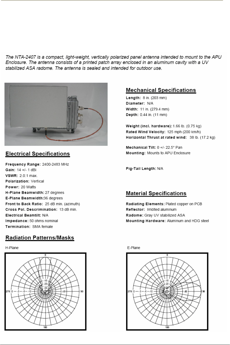
200
Access Point Unit: 2.4G-B-Radio-POE NTPM99AE 01 Rel 1.0 Issue1 May 2007
Appendix B. Antenna
NTA.2407 Panel Antenna (For 11b/g Radio Only)
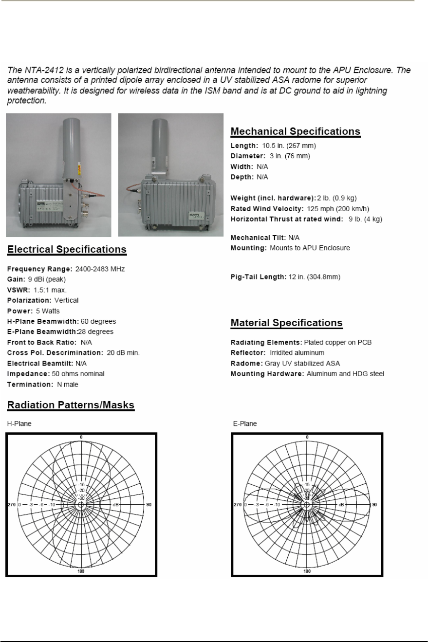
201
Access Point Unit: 2.4G-B-Radio-POE NTPM99AE 01 Rel 1.0 Issue1 May 2007
NTA.2412 Bidirectional Antenna (For 11b/g Radio Only)
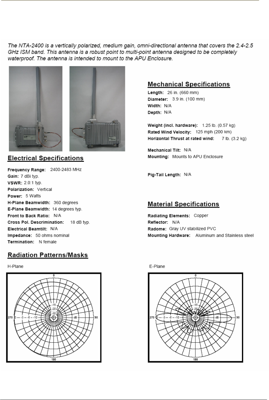
202
Access Point Unit: 2.4G-B-Radio-POE NTPM99AE 01 Rel 1.0 Issue1 May 2007
NTA.2400 Omni directional Antenna (For 11b/g Radio Only)
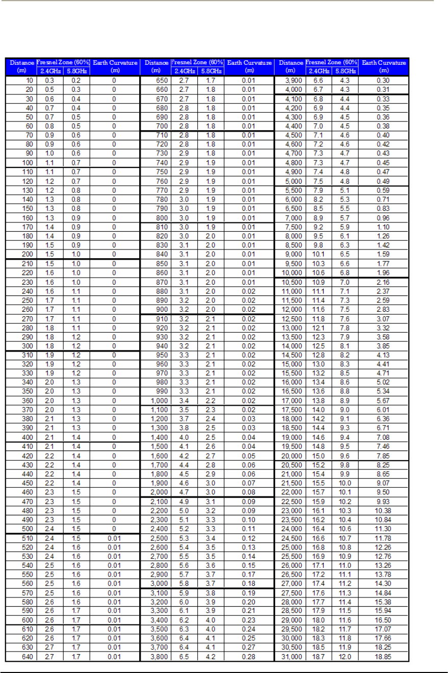
203
Access Point Unit: 2.4G-B-Radio-POE NTPM99AE 01 Rel 1.0 Issue1 May 2007
Appendix C. Link Budget and Distance
Table A.8 Link budget and Distance table
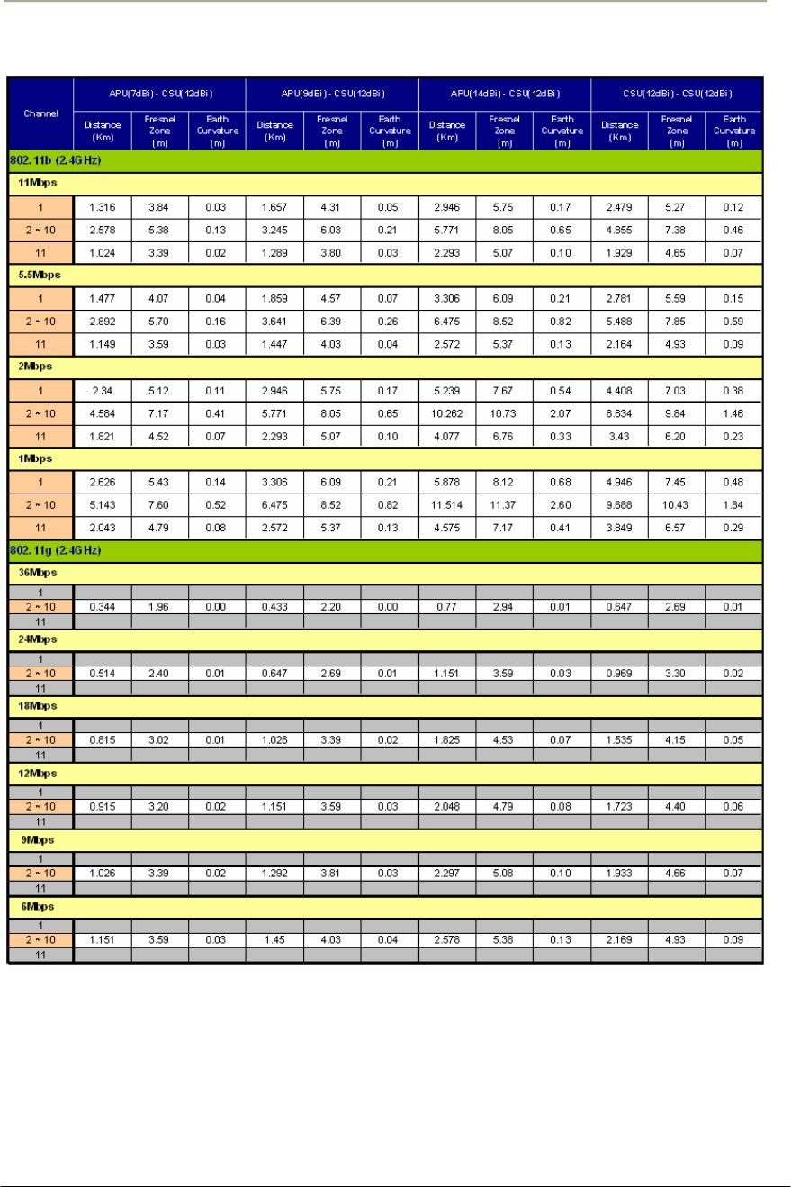
204
Access Point Unit: 2.4G-B-Radio-POE NTPM99AE 01 Rel 1.0 Issue1 May 2007
Table A.9 Reference Data with the certified antennas at 802.11b/11g (2.4GHz)
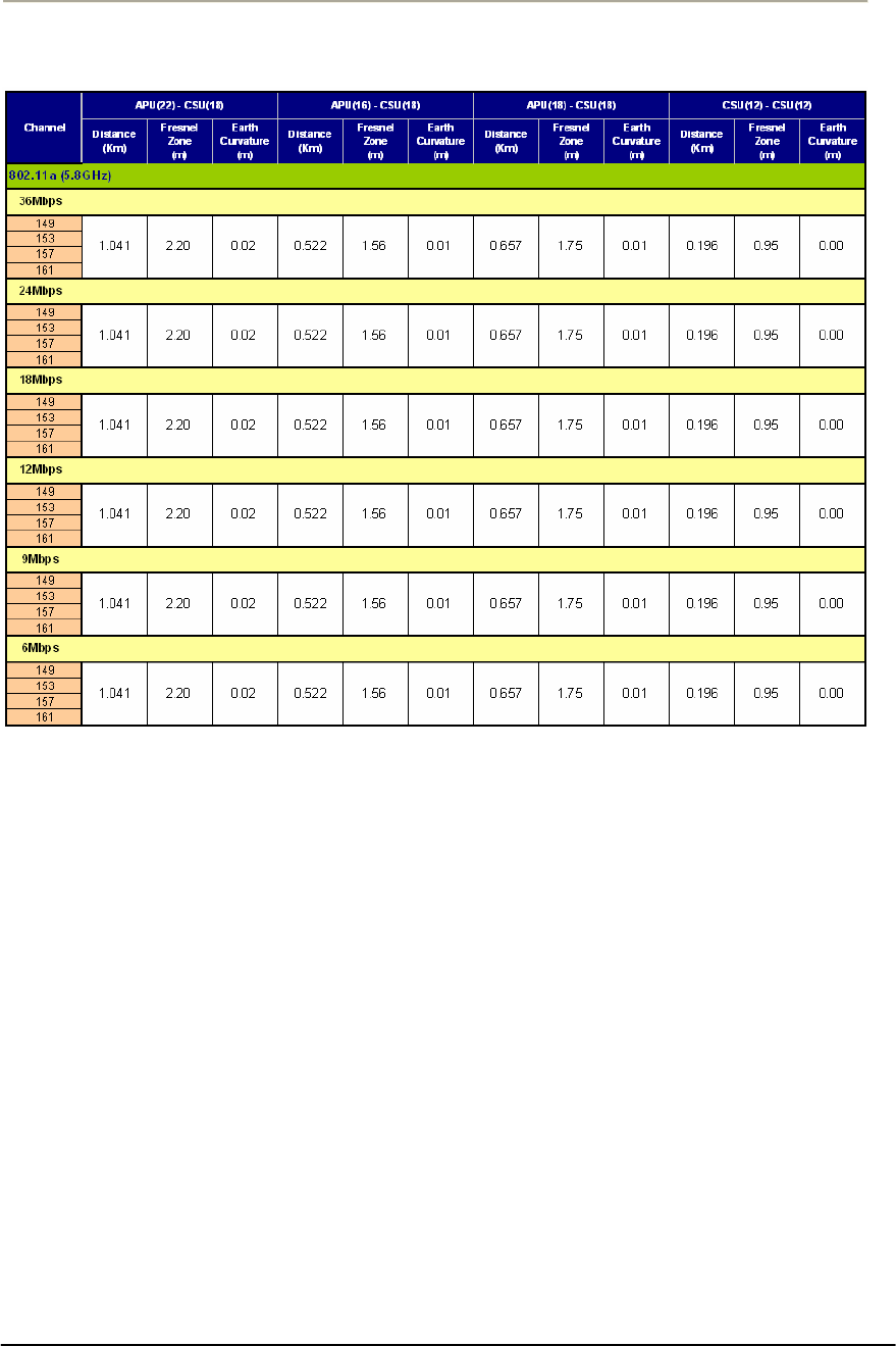
205
Access Point Unit: 2.4G-B-Radio-POE NTPM99AE 01 Rel 1.0 Issue1 May 2007
Table A.10 Reference Data with the certified antennas at 802.11a (5.8GHz)
Note: This table will help you determine a distance and clearance factor of CSU from
APU or CSU ahead of an actual calculation process so that you can figure out the
expected link engineering parameter and restriction at the field.
This table has been calculated with the following assumptions:
1. Transmit Power: Max transmit power values listed in the Appendix A
2. Fade margin: 10dB
3. Antenna cable loss: 0.5dB(CSU), 1dB(APU/2.4GHz)
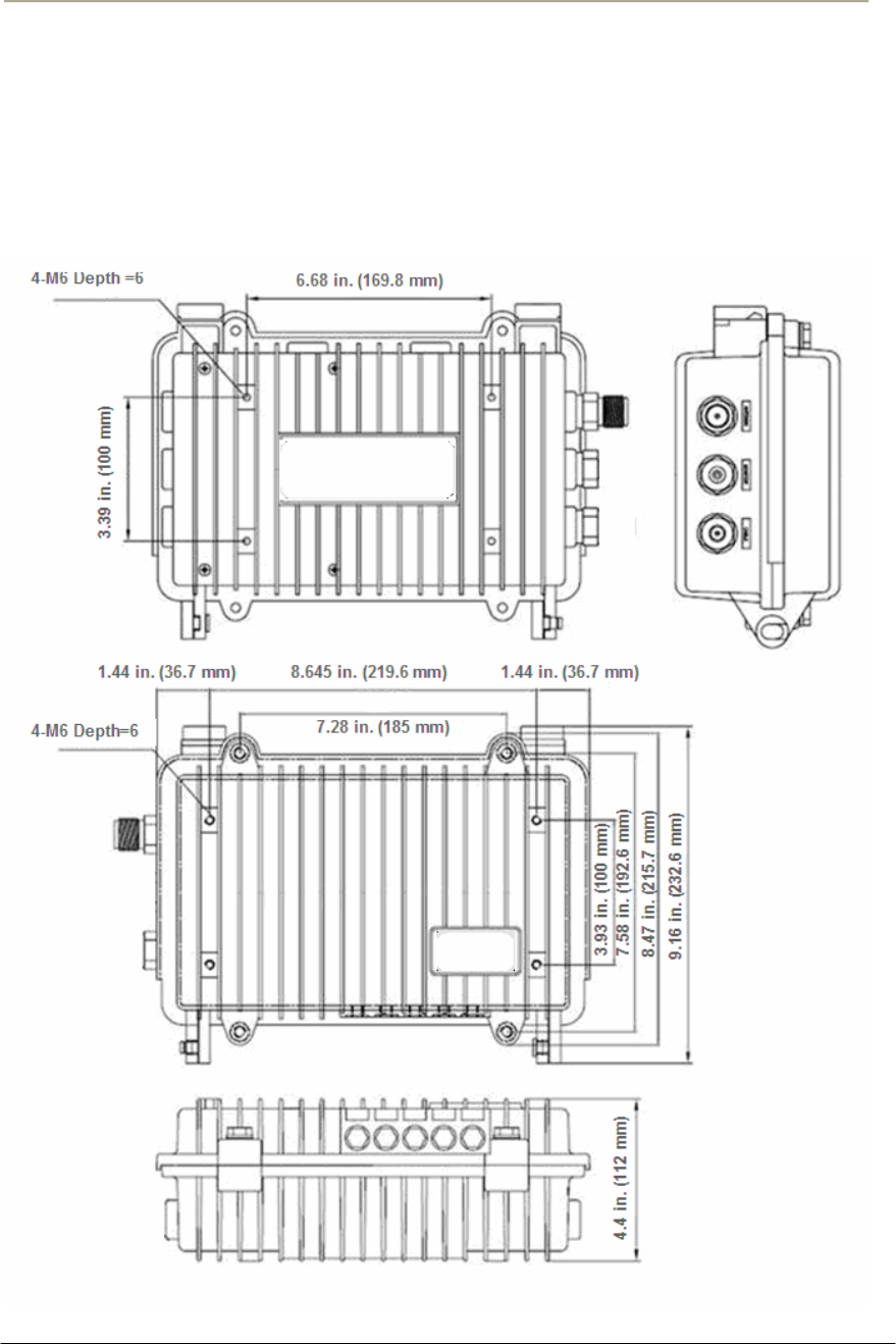
206
Access Point Unit: 2.4G-B-Radio-POE NTPM99AE 01 Rel 1.0 Issue1 May 2007
Appendix D. Enclosure Dimension
Access Point Unit (APU)
Figure A.1 APU Dimension
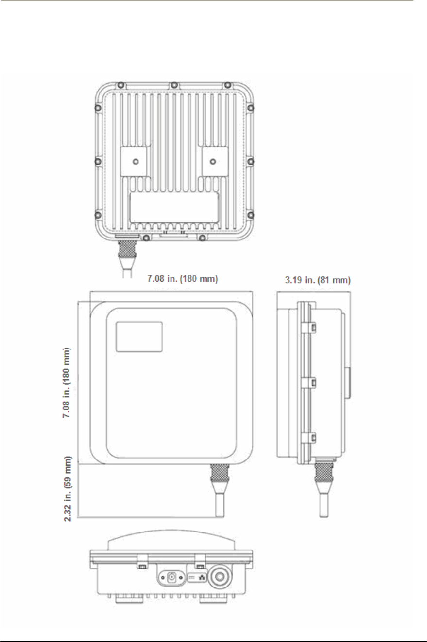
207
Access Point Unit: 2.4G-B-Radio-POE NTPM99AE 01 Rel 1.0 Issue1 May 2007
Corporate Service Unit (CSU)
Figure A.2 CSU Dimension