MUL T LOCK TECHNOLOGIES 81132 ENTR Dongle User Manual
MUL-T-LOCK TECHNOLOGIES LTD ENTR Dongle Users Manual
Users Manual
ENTR Project
Jan, 01, 2017
An ASSA ABLOY Group Brand
Page 1
ENTR Dongle Communication protocol
document
Revision: 6.1
Date 11-01-17
Proprietary Notice
The information contained in this document is proprietary to Mul-T-Lock.
Use or transfer of this document or the information contained herein
without the express written consent of Mul-T-Lock is prohibited.
ENTR Project
Jan, 01, 2017
An ASSA ABLOY Group Brand
Page 2
Rev
Description
Name
Date
Signature
1.0
Initial release
David Termin
06-04-15
2.0
Parag. 3.2- More detailed added.
David Termin
15-04-15
Parag. 4- Unified tables
Add Parag.2.3
Add Parag. 6-Key generation procedure
3.0
Add 'get status' command
07-05-15
4.0
Rearrange step by step procedure on parag. 3
03-06-15
5.0
Delete ,correct status register mapping
David Termin
05-08-15
6.0
Change parag. 4.2 and 3.3.8
18-01-16
6.1
Add FW update capability on parag. 3.3.1
David Termin
11-01-17
Product:
Integration Bridge
Customer:
Mul-T-Lock
APPROVALS:
Title
Name
Date
Signature
Checked By
R&D Manager
Approved By
R&D Manager
Quality Mgmt
Configuration Manager

ENTR Project
Jan, 01, 2017
An ASSA ABLOY Group Brand
Page 3
Contents
1 1. Introduction ....................................................................................................................................................... 4
1.1 Scope ............................................................................................................................................................ 4
1.2 Purpose ........................................................................................................................................................ 4
1.3 Block Diagram ............................................................................................................................................ 4
Figure 1-Block Diagram .......................................................................................................................................... 4
2 USB Dongle ICD ................................................................................................................................................... 5
2.1 Real Estate .................................................................................................................................................. 5
Figure 2- Real Estate, dimensions: (L)57.15 x (W)19.05mm inc. Plastic Cover ................................................. 5
2.1 Temperature ............................................................................................................................................... 6
2.2 Voltage ........................................................................................................................................................ 6
2.3 Current Consumption ................................................................................................................................ 6
3 USB (UART COM port) Overall Description ....................................................................................................... 6
3.1 Open a virtual command window ............................................................................................................. 6
3.2 UART Command format ........................................................................................................................... 6
3.3 Examples of step by step command structure ......................................................................................... 7
3.3.1 First time USB insertion .......................................................................................................................... 7
3.3.2 Search Keys 0x71(see table on paragraph 4.2) ........................................................................................ 7
Figure 6-Search Keys Transaction Message structure ......................................................................................... 7
3.3.3 In response you receive a 0x72 Keysfound status (see paragraph 4.2) .................................................... 7
3.3.4 Getkey 0x74(see table on paragraph 4.2)................................................................................................. 7
Figure 3-Getkey Transaction Message structure .................................................................................................. 8
3.3.5 Unlock 0x7B(see table on paragraph 6) ................................................................................................... 8
Figure 4-Unlock Transaction Message structure .................................................................................................. 8
3.3.6 In response you receive a 0x70 Status (see paragraph 4.2) ...................................................................... 8
3.3.7 Lock 0x7A(see table on paragraph 4.2) ................................................................................................... 8
Figure 5-Lock Transaction Message structure ..................................................................................................... 9
3.3.8 In response you receive a 0x70 Status (see paragraph 4.2) ...................................................................... 9
3.3.9 Get Status 0x7C(see table on paragraph 4.2) ........................................................................................... 9
Figure 5-Lock Transaction Message structure ..................................................................................................... 9
3.3.10 ShowKeysLock 0x73(see table on paragraph 4.2) ............................................................................ 10
Figure 7-ShowsKeysLock Transaction Message structure ................................................................................ 10
4 Remote Unit Commands...................................................................................................................................... 10
4.1 Error codes ............................................................................................................................................... 10
4.2 External control through BLE master commands(Com port) ............................................................. 10
5 BLE Module Flow ENTR .............................................................................................................................. 11
6 Pending key generation process through the smartphone App ............................................................................ 13
7 For radio enclosure .............................................................................................................................................. 17
7.1 Radio Frequency Interference (RFI) (FCC 15.105) .............................................................................. 17
7.2 Labeling Requirements (FCC 15.19) ...................................................................................................... 17
7.3 Modifications (FCC 15.21) ...................................................................................................................... 18
7.4 RF Exposure info ( FCC 2.1093)-for module radio ............................................................................... 18
1
ENTR Project
Jan, 01, 2017
An ASSA ABLOY Group Brand
Page 4
1. Introduction
1.1 Scope
This document describes the spec for the BLE USB dongle communication protocols. The
module will serve the SW engineers and integrators.
An integrator is a person that owns the knowhow of the home automation API protocol and
commands and how to integrate it to our BLE API.
Along with that it will attach the SPI master and UART/USB source codes.
1.2 Purpose
The protocol addresses the following needs: Request of a general system status. Notify the BLE
when individual statuses are changed. Allow the BLE to change system settings and etc.
The BLE USB dongle in intend to integrate to a server that supports USB interface.
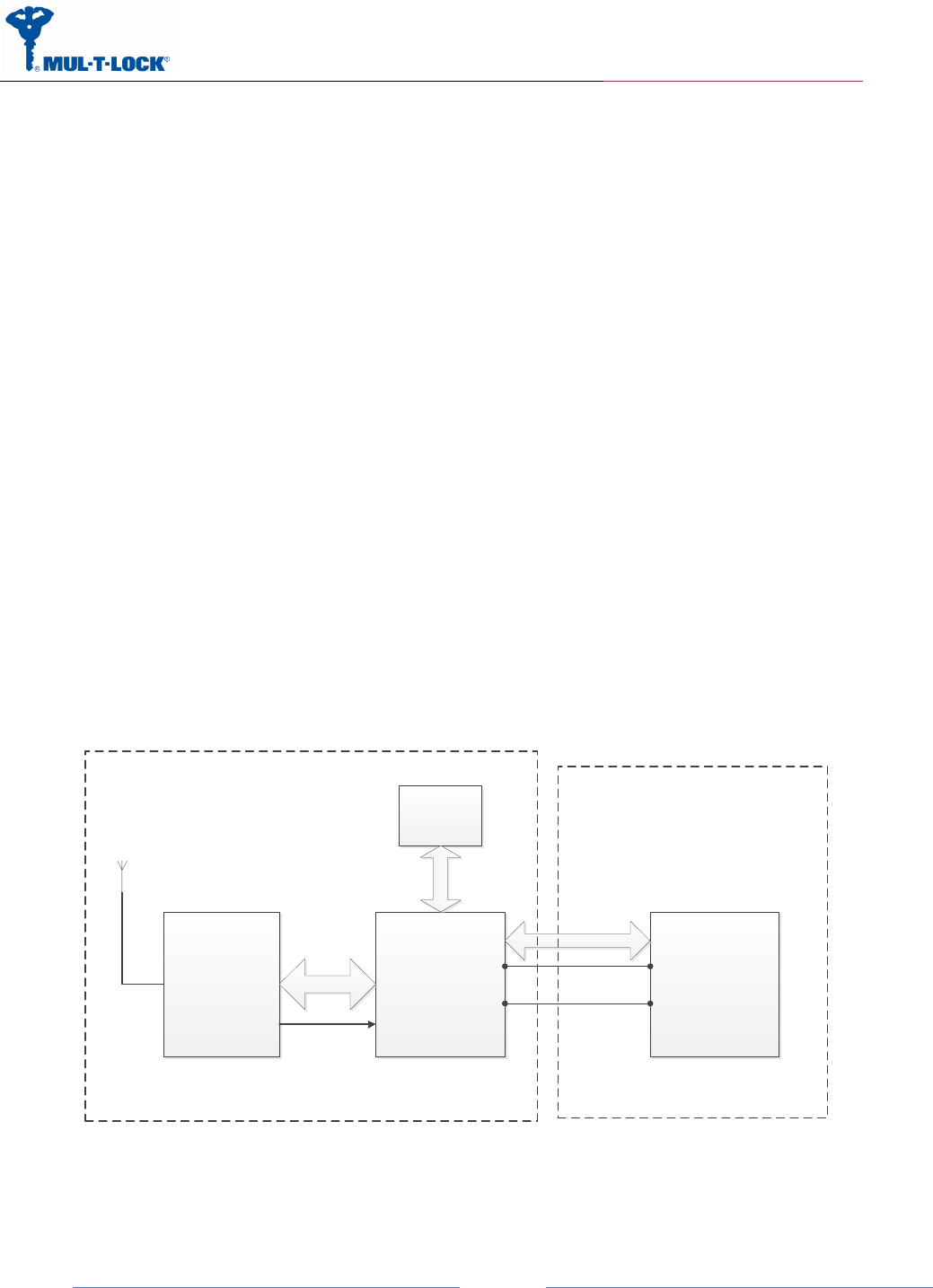
1.3 Block Diagram
ST BlueNRG Freescale MCU
MK21DN512VMC5
SPI
SPI
Master
SPI Slave
Interrupt
HW
Encryption
NXP7001
I2C
Integrator Server/
PC
USB
USB Slave USB Host
BLE Module
5V
GND
Integrator
Server/PC
Figure 1-Block Diagram
ENTR Project
Jan, 01, 2017
An ASSA ABLOY Group Brand
Page 5
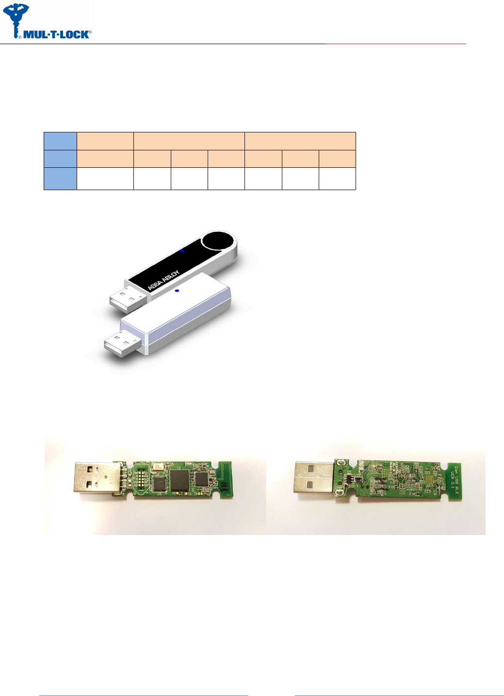
2 USB Dongle ICD
No ICD needed, insert to any standard USB host port.
2.1 Real Estate
external [mm]
PCB [mm]
enclosure
Length
Width
Height
Length
Width
Height
1
P-220705
57.15
19.05
12.7
52.08
14.74
1.57
Figure 2- Real Estate, dimensions: (L)57.15 x (W)19.05mm inc. Plastic Cover

ENTR Project
Jan, 01, 2017
An ASSA ABLOY Group Brand
Page 6
2.1 Temperature
-10~+60C.
2.2 Voltage
+5V+5%, Low power (<100ma) USB 2.0 standard
2.3 Current Consumption
Max. 30ma@5V.
3 USB (UART COM port) Overall Description
3.1 Open a virtual command window
Install the windows driver (32/64 bit) into the PC.
Insert the BLE dongle into the Server/PC USB host port.
Check that the driver recognized the dongle.
Open a terminal (etc. putty/TeraTerm) and select the appropriate virtual COM port.
Enable echo on.
Set the speed to 115200bps and 8, N, 1,
Now you can write the command as it appears in paragraph 3.3.
3.2 UART Command format
Virtual COM protocol generically implements the same protocol as in SPI between Integrator -
MCU and BLE-module MCU.
The same conceptual communication is done as in SPI, starting from the command, and
excluding the header.
Each command is finished with line-end, instead of transmitting the length in the header.

ENTR Project
Jan, 01, 2017
An ASSA ABLOY Group Brand
Page 7
All data is sent as hex data printed as two 0-F textual digits. Strings can for example be
converted using https://www.branah.com/ascii-converter, by putting the textual string in the
ASCII field, selecting “Remove 0x” checkbox, and copying the values in “Hex” window.
No delimiters between values.
For example: Send a byte of 0xAB 0xF0, need to send the string "ABF0".
3.3 Examples of step by step command structure
3.3.1 First time USB insertion
When inserting the dongle in the USB port you have to wait at list 6 seconds before sending
first command (See BLE USB-Dongle Bootloader user guide for FW update feature).
3.3.2 Search Keys 0x71(see table on paragraph 4.2)
Figure 6-Search Keys Transaction Message structure
Search Keys
71
3.3.3 In response you receive a 0x72 Keysfound status (see paragraph 4.2)
3.3.4 Getkey 0x74(see table on paragraph 4.2)
On the Getkey command you have to insert the ID that you received on message 72 and
afterwards the key hex value that have been generate for you in your smartphone.
Dongle/UART
71
ENTR Project
Jan, 01, 2017
An ASSA ABLOY Group Brand
Page 8
Figure 3-Getkey Transaction Message structure
Getkey 1 123456
7401313233343536(ASCII)
After sending the GetKey command you will receive an FE(acknowledge) or FF(Non
acknowledge) response.
3.3.5 Unlock 0x7B(see table on paragraph 6)
Figure 4-Unlock Transaction Message structure
Unlock
7B506176656c6f636b00(ASCII)
The 506176656c6f636b00 is the lock name that you receive from the 0x72 message.
After sending the Unlock command you will receive an FE(acknowledge) or FF(Non
acknowledge) response.
The search Keys(0x71) and getKey(0x74) commands are only used for receiving a pending key
for the dongle , afterwards you can use the lock/unlock/status commands only.
3.3.6 In response you receive a 0x70 Status (see paragraph 4.2)
The status register contain the door status: Door is closed, Lock is locked, Muted,
Automatic locking, Charging and battery condition.
3.3.7 Lock 0x7A(see table on paragraph 4.2)
Dongle/UART
7401313233343536
Dongle/UART
7B506176656c6f636b00
ENTR Project
Jan, 01, 2017
An ASSA ABLOY Group Brand
Page 9
Figure 5-Lock Transaction Message structure
Lock
7A506176656c6f636b00(ASCII)
The 506176656c6f636b00 is the lock name that you receive from the 0x72 message.
After sending the lock command you will receive an FE(acknowledge) or FF(Non acknowledge)
response.
3.3.8 In response you receive a 0x70 Status (see paragraph 4.2)
The status register contain the door status: Door is closed, Lock is locked, Muted,
Automatic locking, Charging and battery condition.
3.3.9 Get Status 0x7C(see table on paragraph 4.2)
Figure 5-Lock Transaction Message structure
Lock
7C506176656c6f636b00(ASCII)
The status register(0x70) contain the door status: Door is closed, Lock is locked, Muted,
Automatic locking, Charging and battery condition.
After sending the status command you will receive an FE(acknowledge) or FF(Non
acknowledge after timeout) response.
Dongle/UART
7A506176656c6f636b00
Dongle/UART
7C506176656c6f636b00
ENTR Project
Jan, 01, 2017
An ASSA ABLOY Group Brand
Page
10
3.3.10 ShowKeysLock 0x73(see table on paragraph 4.2)
Figure 7-ShowsKeysLock Transaction Message structure
ShowKeyLock 0
7300(ASCII)
4 Remote Unit Commands
The tables below are Commands, statuses and errors and are defines as the message part.
4.1 Error codes
Code
Meaning
0x01
CRC Error
0x02
Unknown command
0x03
Address error
0x04
Command failed
0x05
Data error
0x10
No stored eKey for this lock
0x11
Error communicating with lock
0x12
Permission denied
0x13
Wrong PIN
0x14
Locked out due to many wrong PINs attempts
0x7F
Unspecified error
4.2 External control through BLE master commands(Com port)
Name
Code
Data
Meaning
Remote Unlock
0x7B
LockName+’\0’
Actual sent length can be variable, with length in
the header. Max allowed total length with trailing
0 is 30 bytes.
ACK will be sent in reply when successfully
managed sending a unlock command (eKey
Dongle/UART
7300

ENTR Project
Jan, 01, 2017
An ASSA ABLOY Group Brand
Page
11
compared).
NACK will be sent on errors with following error
codes 0x10-0x12.
Remote Lock
0x7A
LockName+’\0’
Usage identical to remote unlock command
Status
0x70
StatusBitmap+
BatteryPercent
The status bits are: {X, Y, Charging ,Door is open,
Lock is unlocked, Muted, Manual locking, 1}
X,Y
00(>20%) -- High state of charge.
01(<10%) -- Low state of charge.
10(<20%) -- Medium state of charge.
Get Status
0x7C
LockName+’\0’
Usage identical to remote Lock/unlock command
Search Keys
0x71
None
Command to start scanning for locks with pending
keys
ACK reply when request received and search
started
KeysFound
0x72
Count/ID(1 byte) +
LockName+’\0’
As a first message, Count/ID will act as Count and
say how much Locks is found with pending keys.
On all messages, Count/ID acts as ID and will
show identification number of the current lock
with pending keys. Its values are in range 1 to
Count.
If Count/ID is 0, then LockName will not exist.
Max lock name is 8 character, If the lock name is
less than 8 character the FW will add 20(space) to
complete to 8 characters and 00 for end of string.
If lock name is exactly 8 characters the FW will
add 00 only for end of string.
ShowKeyLock
0x73
ID (1 byte)
Request to get KeysFound for specific given ID.
GetKey
0x74
ID (1 byte)+
PIN (6 bytes)
ID of the lock from which to request the pending
key
PIN is alphanumeric code to get this key
ACK is replied when key is received
NACK can be sent with codes 0x11 and 0x13
ACK
0xFE
None
NACK
0xFF
Error code
Factory reset
0x06
0x80
Resets all persistent memory and erases all stored
keys
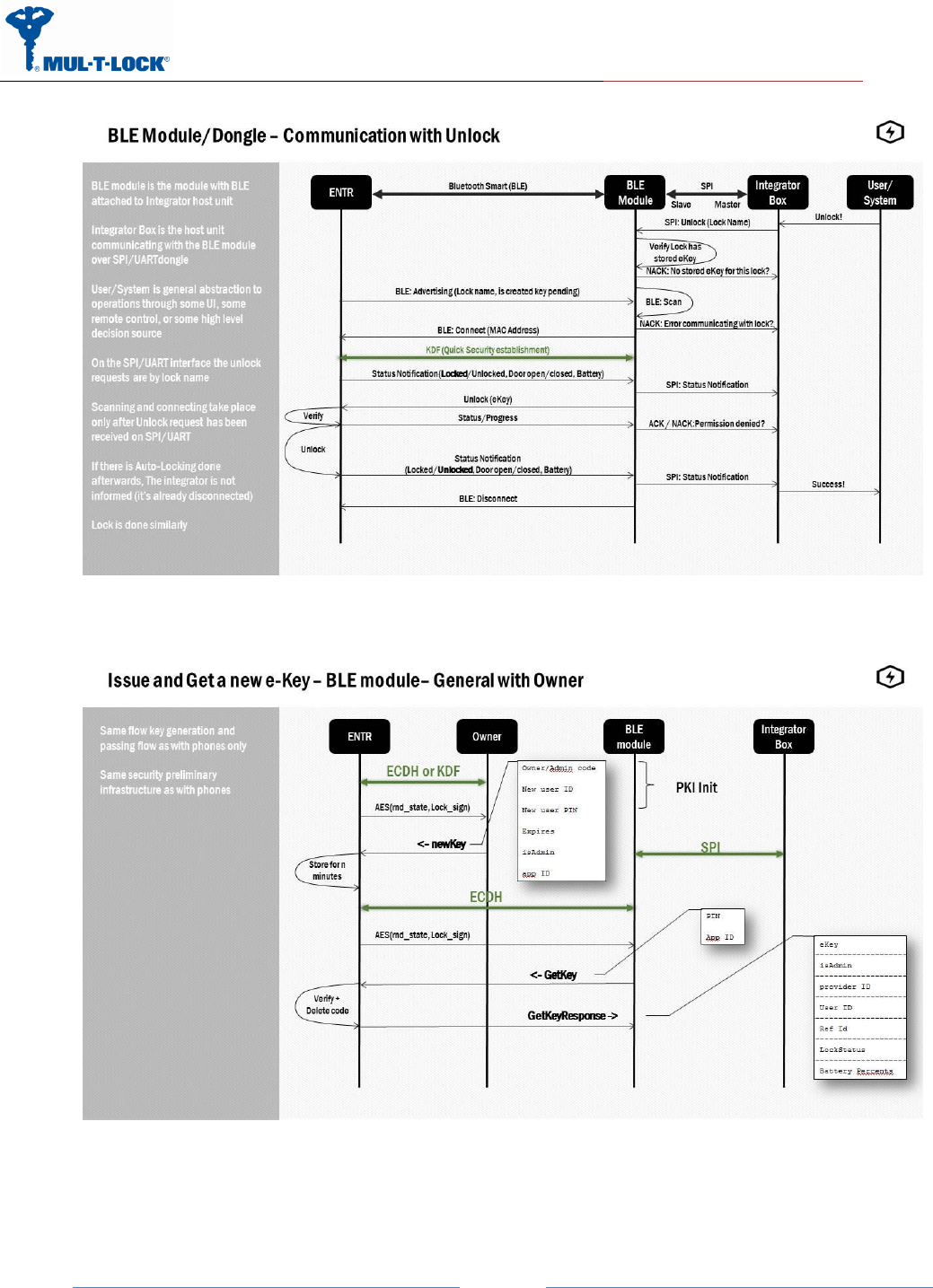
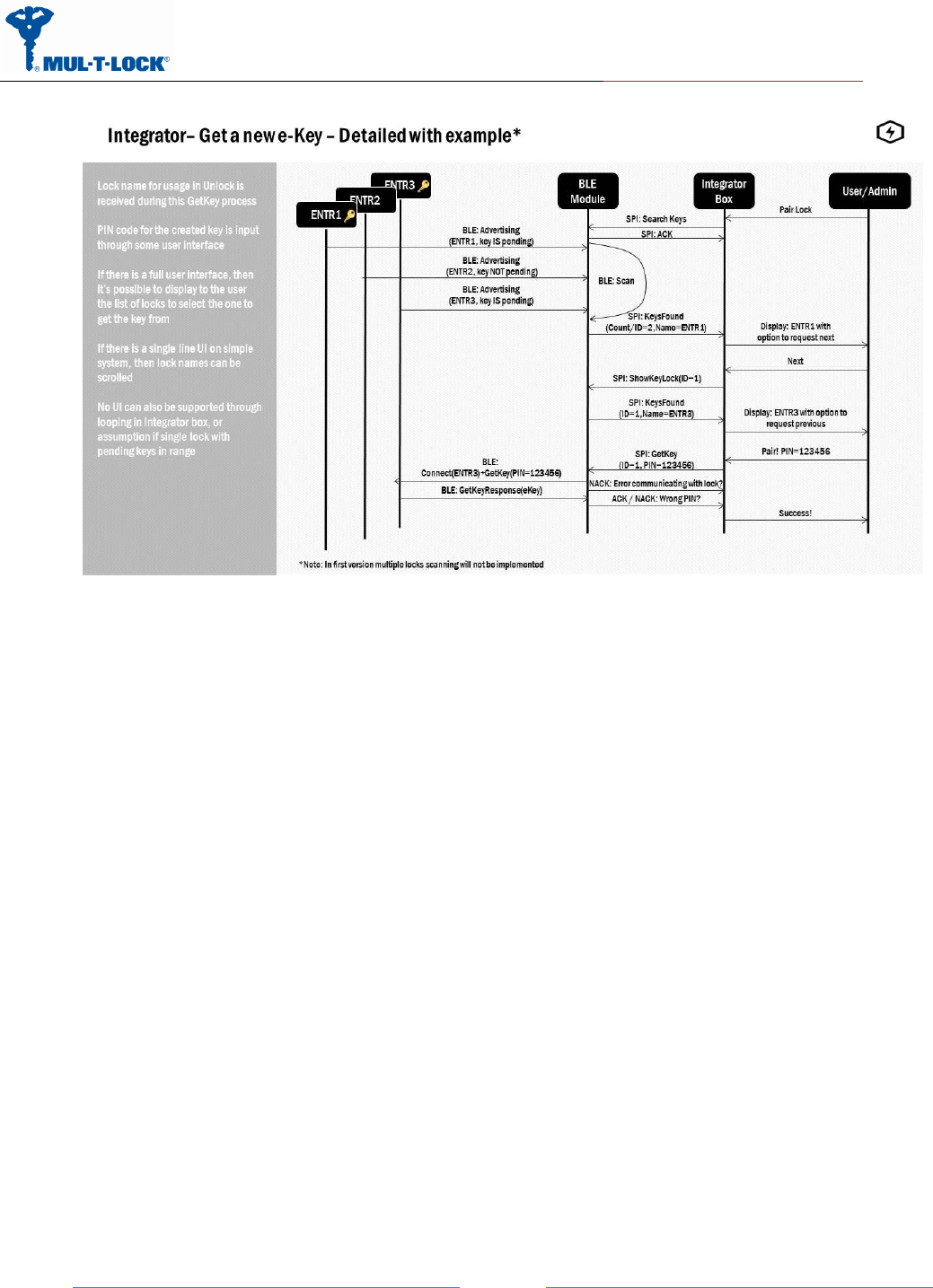
5 BLE Module Flow ENTR
This flow describes all flow between the system parts, this document cover the communication
between the integrator box and the BLE module/dongle.
ENTR Project
Jan, 01, 2017
An ASSA ABLOY Group Brand
Page
12
ENTR Project
Jan, 01, 2017
An ASSA ABLOY Group Brand
Page
13
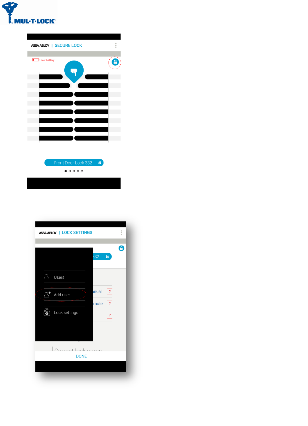
6 Pending key generation process through the
smartphone App
Assuming the ENTR DU is already paired to the smartphone.
Get into “Lock Settings” by tapping the lock icon:
ENTR Project
Jan, 01, 2017
An ASSA ABLOY Group Brand
Page
14
Tap on “Add User”
ENTR Project
Jan, 01, 2017
An ASSA ABLOY Group Brand
Page
15
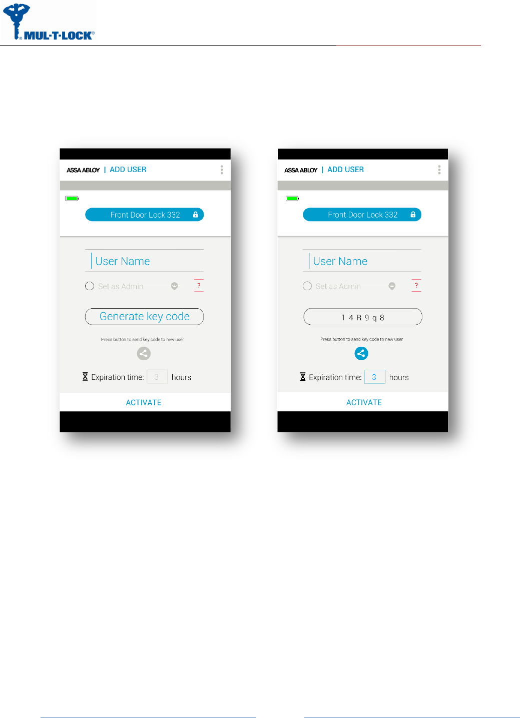
Enter the user name, generate the key code, and share or remember the code for the process
of getting the key through the integration unit. Press “ACTIVATE”:
ENTR Project
Jan, 01, 2017
An ASSA ABLOY Group Brand
Page
16
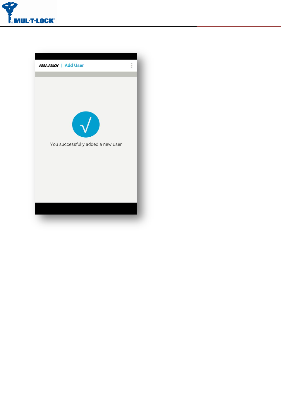
On Success you will see the following screen:
From this moment, for the predefined expiration time, the key will be waiting in the lock until it
will be pulled from the lock using the code. The key pulling can be done by the integration unit
or any other phone user possessing the code.

ENTR Project
Jan, 01, 2017
An ASSA ABLOY Group Brand
Page
17
(FCC) Statement Labelling
7 For radio enclosure Federal
Communications Commission requirement for
small device statement (FCC15.19(3))
This device complies with part 15 of the FCC Rules. Operation is subject to the following
two conditions: (1) This device may not cause harmful interference, and (2) this device must
accept any interference received, including interference that may cause undesired operation.
7.1 Radio Frequency Interference (RFI) (FCC 15.105)
This equipment has been tested and found to comply with the limits for Class B digital devices
pursuant to Part 15 of the FCC Rules. These limits are designed to provide reasonable
protection against harmful interference in a residential environment. This equipment
generates, uses, and can radiate radio frequency energy, and if not installed and used in
accordance with the instruction manual, may cause harmful interference to radio
communications. However, there is no guarantee that interference will not occur in a particular
installation. If this equipment does cause harmful interference to radio or television reception,
which can be determined by turning the equipment off and on, the user is encouraged to try
and correct the interference by one or more of the following measures:
•
Reorient or relocate the receiving antenna.
•
Increase the separation between the equipment and the receiver.
•
Connect the equipment into an outlet on a circuit different from that to which the
receiver is connected.
•
Consult the dealer or an experienced radio/TV technician for help.

ENTR Project
Jan, 01, 2017
An ASSA ABLOY Group Brand
Page
18
Product FCC ID: 2AHH881132
7.3 Modifications (FCC 15.21)
Changes or modifications to this equipment not expressly approved by Mul-T-Lock®
may void the user’s authority to operate this equipment.
7.4 RF warning for Portable device
The device has been evaluated to meet general RF exposure requirement. The device can be
used in portable exposure condition without restriction.