MUL T LOCK TECHNOLOGIES 81134 ENTR Bridge User Manual
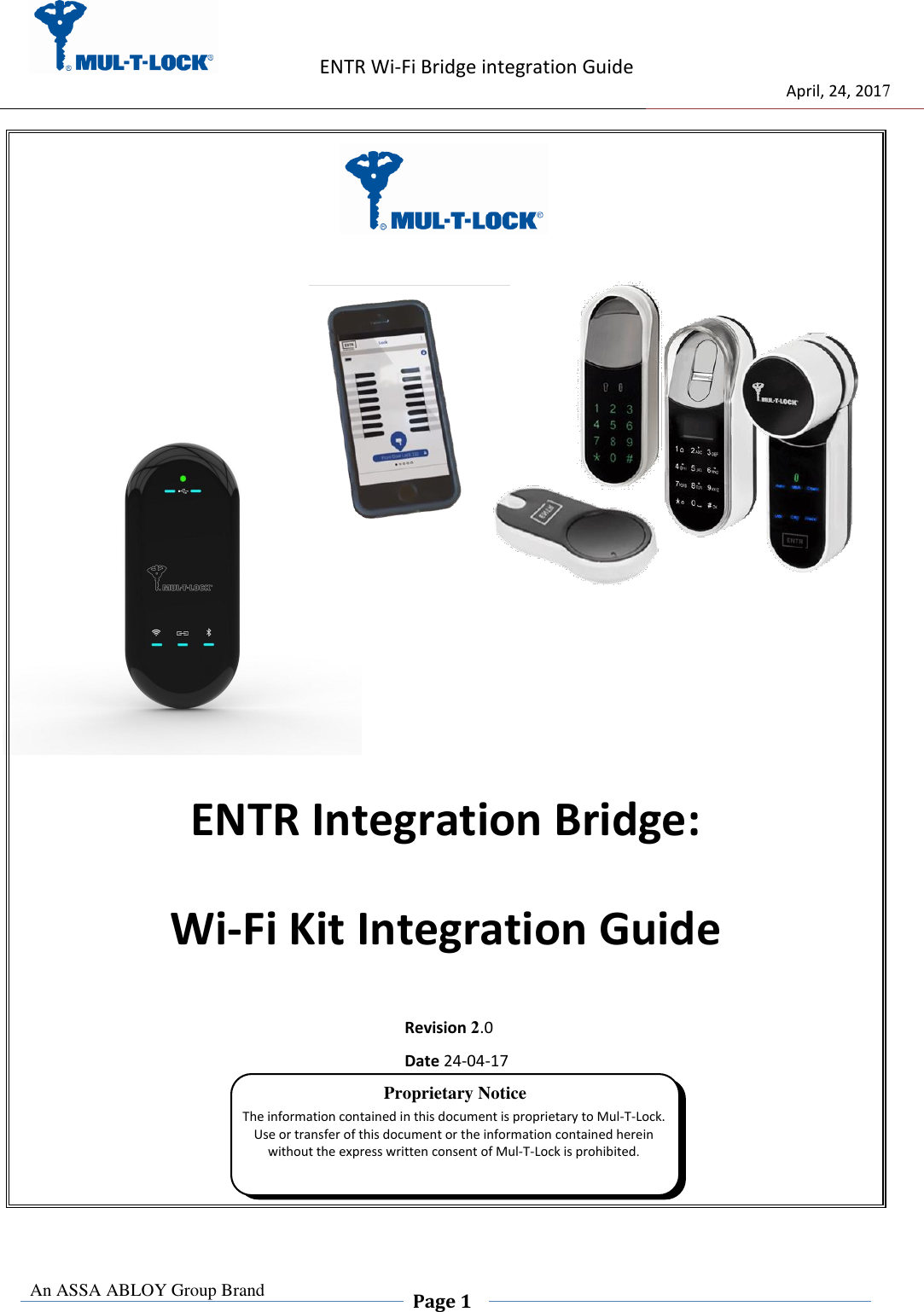
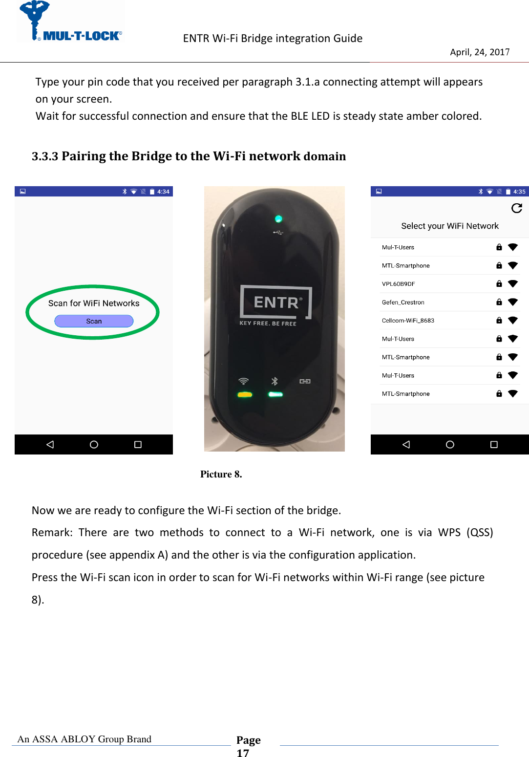
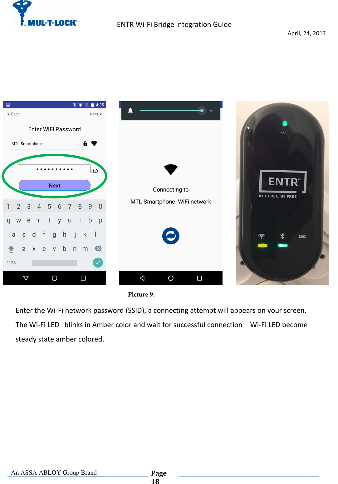
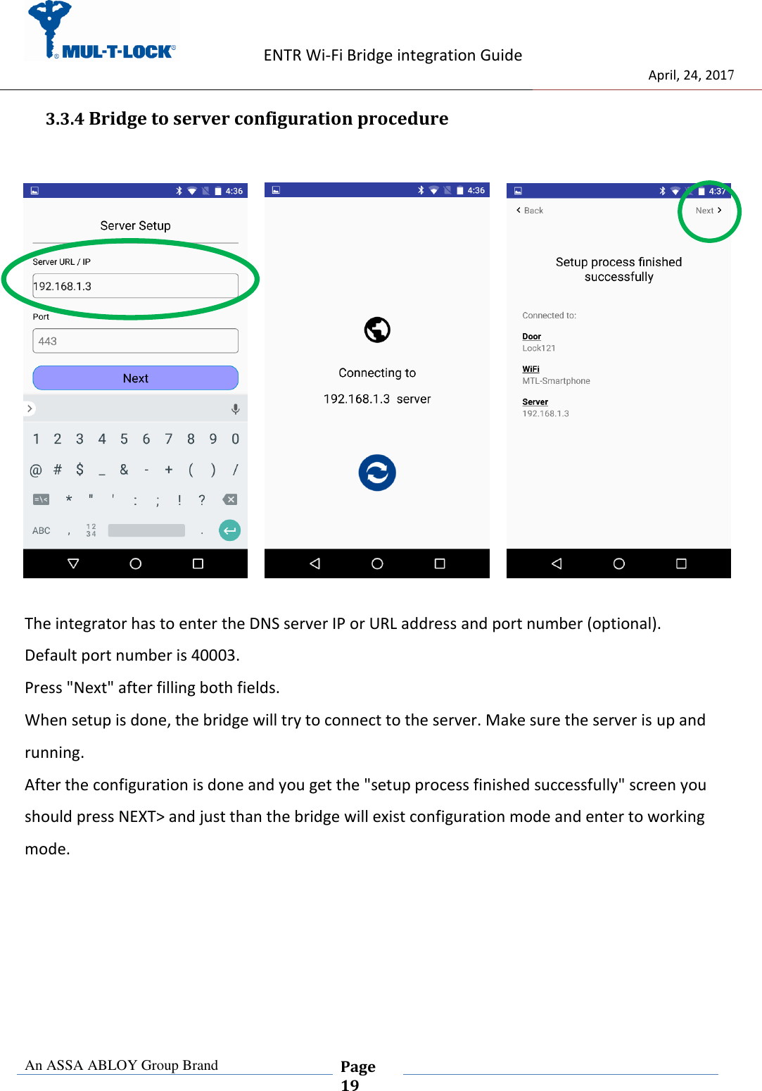
MUL-T-LOCK TECHNOLOGIES LTD ENTR Bridge Users Manual
UserManual.wiki
>
MUL T LOCK TECHNOLOGIES
>
81134 User Manual
Users Manual
Navigation menu
Upload a User Manual
Namespaces
Wiki Guide
HTML
PDF
Info
Views
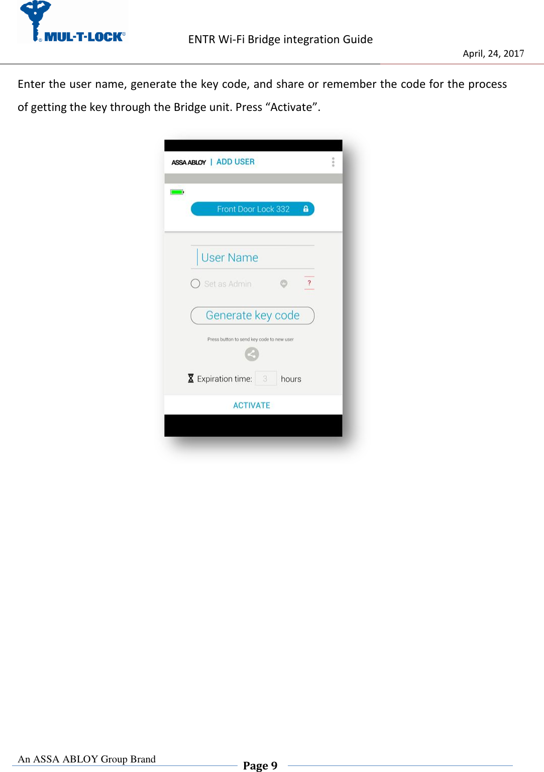
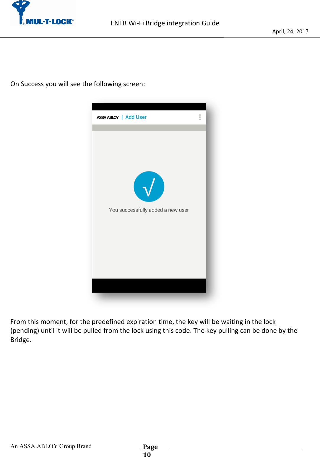
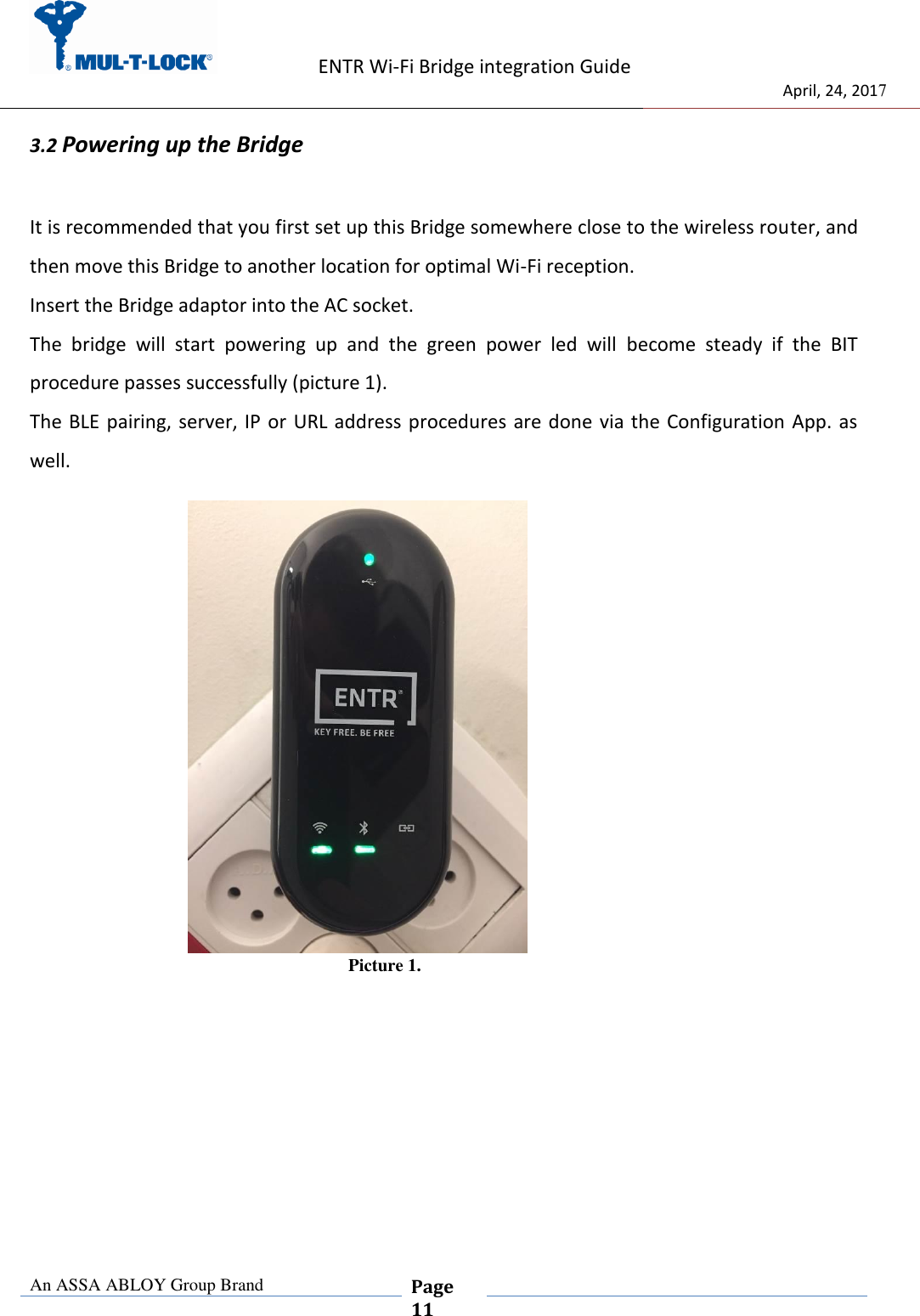
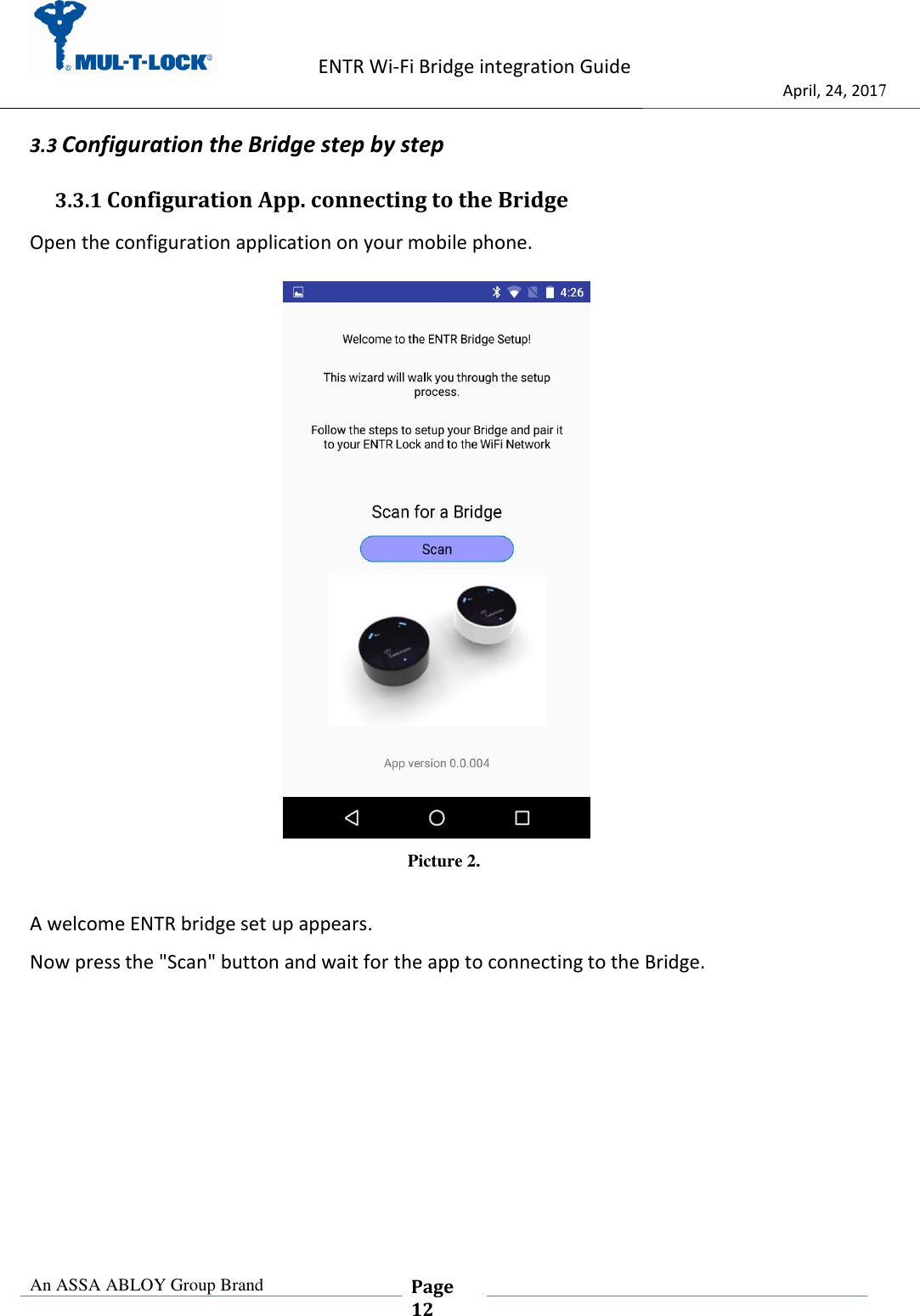
User Manual
Discussion / Help
Navigation