MUL T LOCK TECHNOLOGIES 81134 ENTR Bridge User Manual
MUL-T-LOCK TECHNOLOGIES LTD ENTR Bridge Users Manual
Users Manual
ENTR Wi-Fi Bridge integration Guide
April, 24, 2017
An ASSA ABLOY Group Brand
Page 1
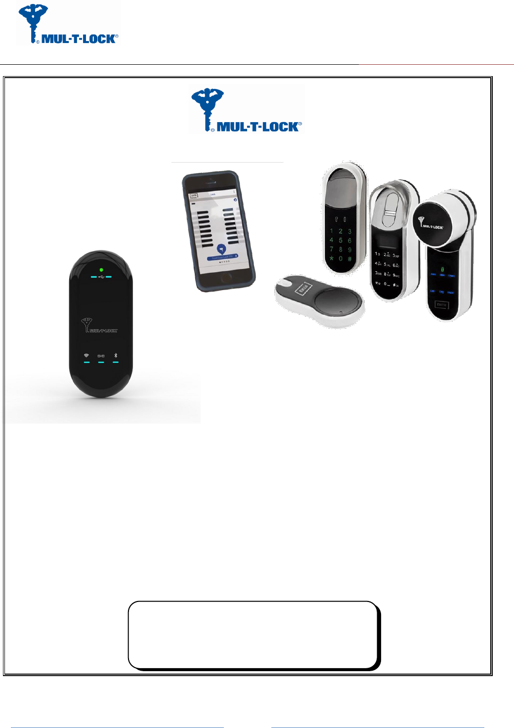
ENTR Integration Bridge:
Wi-Fi Kit Integration Guide
Wi-
Wi-Fi kit
Revision 2.0
Date 24-04-17
Proprietary Notice
The information contained in this document is proprietary to Mul-T-Lock.
Use or transfer of this document or the information contained herein
without the express written consent of Mul-T-Lock is prohibited.
1

ENTR Wi-Fi Bridge integration Guide
April, 24, 2017
An ASSA ABLOY Group Brand
Page 2
Rev
Description
Name
Date
Signature
0.0
Initial
David Termin
14-04-16
1.0
First release
David Termin
26-04-16
2.0
Change web configuration method to Mobile
App. configuration and procedure reordering
David Termin
26-04-17
Product:
Integration Bridge
Customer:
ASSA ABLOY
APPROVALS:
Title
Name
Date
Signature
Checked By
R&D Manager
Ehud Dinerman
Approved By
R&D Manager
Ehud Dinerman
Quality Mgmt
Configuration Manager

ENTR Wi-Fi Bridge integration Guide
April, 24, 2017
An ASSA ABLOY Group Brand
Page 3
Table of Contents
1. Package contents........................................................................................................................................................ 4
2. HMI and Led Indicators............................................................................................................................................. 4
3. Getting Started ........................................................................................................................................................... 7
3.1 Generating BLE key with the owner Smartphone .............................................................................................. 8
3.2 Powering up the Bridge .................................................................................................................................... 11
3.3 Configuration the Bridge step by step .............................................................................................................. 12
3.3.1 Configuration App. connecting to the Bridge ............................................................................................. 12
3.3.2 Pairing the Bridge to the ENTR BLE domain ............................................................................................ 13
3.3.3 Pairing the Bridge to the Wi-Fi network domain ........................................................................................ 17
3.3.4 Bridge to server configuration procedure ................................................................................................... 19
4. For radio enclosure .................................................................................................................................................. 20
4.1 Radio Frequency Interference (RFI) (FCC 15.105) ...................................................................................... 20
4.2 Labeling Requirements (FCC 15.19) .............................................................................................................. 20
4.3 Modifications (FCC 15.21) .............................................................................................................................. 21
4.4 RF Exposure info (FCC 2.1093)-for module radio ....................................................................................... 21
Appendix A ............................................................................................................................................................. 22
ENTR Wi-Fi Bridge integration Guide
April, 24, 2017
An ASSA ABLOY Group Brand
Page 4
1. Package contents
1 x Bridge unit.
1 x Wi Fi kit integration guide.
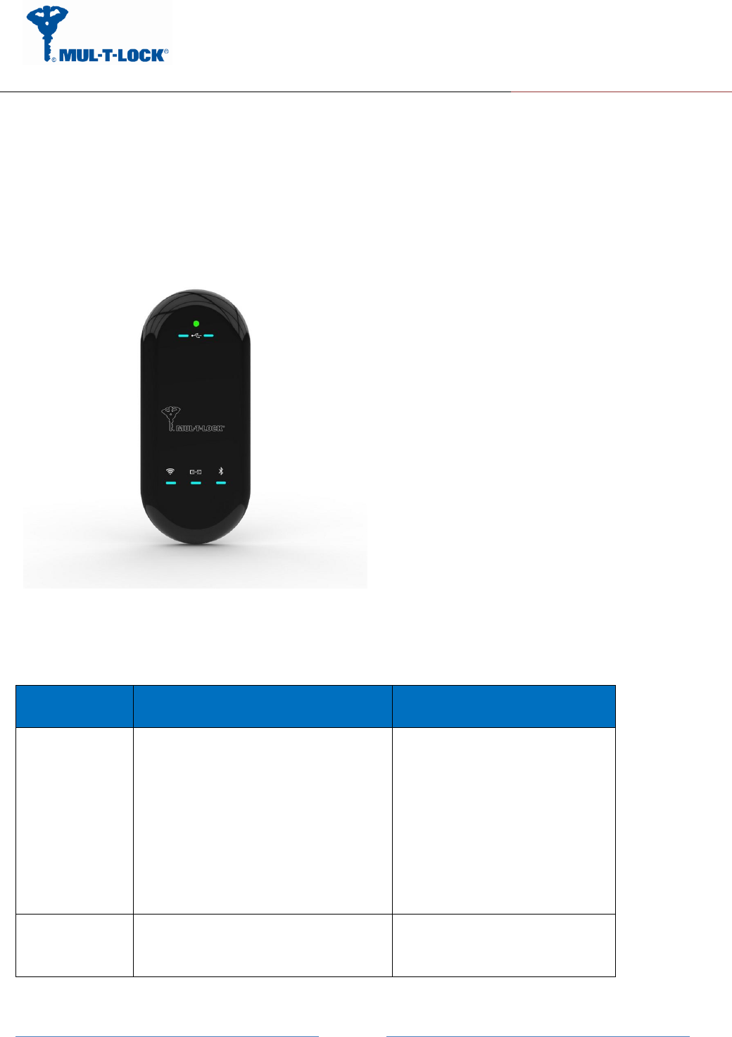
2. HMI and Led Indicators
LED/Push
Button
Description
Remarks
Power
Off-Power is not supplied to the
Bridge
Solid Green-The Bridge is on and
BIT was successful.
Solid Red-BIT failed.
Blinking Green-Bridge is in power
up mode.
Blinking Red-Firmware upgrading
is in progress.
BLE
Off-The BLE radio is off.
Solid Green- The BLE radio is
operating.
Amber Color = Red + Green

ENTR Wi-Fi Bridge integration Guide
April, 24, 2017
An ASSA ABLOY Group Brand
Page 5
Blinking Green- Data is send or
receives.
Solid Amber: Joined a piconet
network successfully.
Blinking Amber: Scan activity
Solid Red: Failed to pair.
Wi-Fi
Off-The 2.4GHz radio is off.
Solid Green- The 2.4GHz radio is
operating.
Blinking Green- Data is send or
receives.
Solid Amber: Joined Wi-Fi network
successfully.
Blinking Amber: Wi-Fi Tx/Rx
activity.
Solid Red: Failed to join
Wi-Fi network.
Blinking White: WPS in process.
Solid White: WPS end process.
White Color = Red + Green +
Blue
USB (ZigBee
example)
ZigBee
Bridge:
Solid Green: Joined ZigBee PAN
successfully
Blinking Green: ZigBee TX/Rx
activity.
Solid Red: Failed to join
End Device:
Solid Green: Joined ZigBee PAN
successfully
Blinking Green: ZigBee TX/Rx
activity.
Solid Red: Failed to join ZigBee
PAN/Parent node removed
AA ZigBee
(example)
Module
ZigBee
Bridge:
Solid Green: Joined ZigBee PAN
successfully
Blinking Green: ZigBee TX/Rx
activity.
Solid Red: Failed to join
End Device:
Solid Green: Joined ZigBee PAN

ENTR Wi-Fi Bridge integration Guide
April, 24, 2017
An ASSA ABLOY Group Brand
Page 6
successfully
Blinking Green: ZigBee TX/Rx
activity.
Solid Red: Failed to join ZigBee
PAN/Parent node removed
Ethernet (RJ45
connector)
Solid Green- Link is up, no Activity.
Blinking Green- Link activity on the
port.
Off- Link is down.
Solid Yellow- 100Mbps speed.
Off- 10Mbps speed.
WPS push
Button
This button lets you use WPS to
join the Wi-Fi network without
typing the Wi-Fi password.
The Wi-Fi LED blinks white during
this process and then lights solid
white.
Factory Reset
push Button
Press the reset button for 3
seconds in order to return to
default settings.

ENTR Wi-Fi Bridge integration Guide
April, 24, 2017
An ASSA ABLOY Group Brand
Page 7
3. Getting Started
The Bridge is connecting to various ecosystem domains, the first one is BLE connectivity to the
ENTR lock, the second is to the Wi-Fi home network and the last one is to the server (integrator
cloud).
In order to configure/pair all three of the above we are using dedicated configuration
application.
Assuming the ENTR DU is already paired to the smartphone the bridge is considered as an ENTR
user and for that the ENTR App. owner has to add this user to the ENTR system in the following
procedure:
After configuring the ENTR per "ENTR user manual" and use the "ENTR™ lock App User Manual"
go through the "set owner" and "find lock”, now you can add a new user (Bridge) per paragraph
3.1.
ENTR Wi-Fi Bridge integration Guide
April, 24, 2017
An ASSA ABLOY Group Brand
Page 8
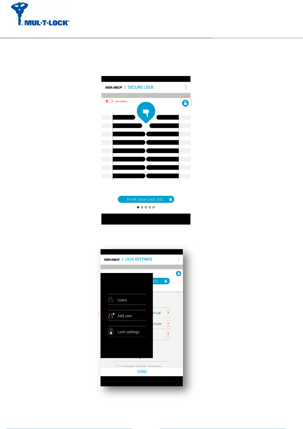
3.1 Generating BLE key with the owner Smartphone
Get into “Lock Settings” by tapping the lock icon:
Tap on “Add User”
ENTR Wi-Fi Bridge integration Guide
April, 24, 2017
An ASSA ABLOY Group Brand
Page 9
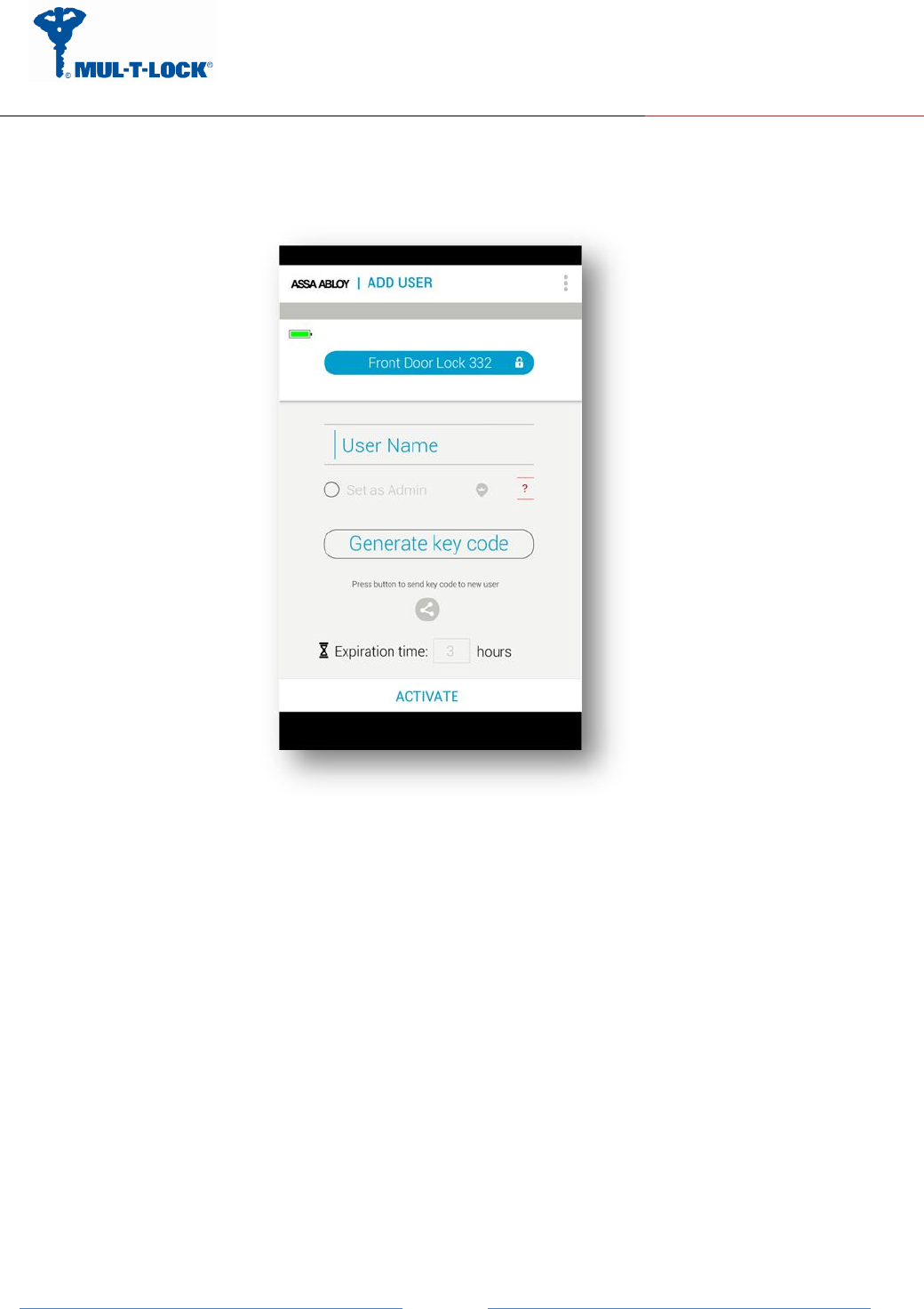
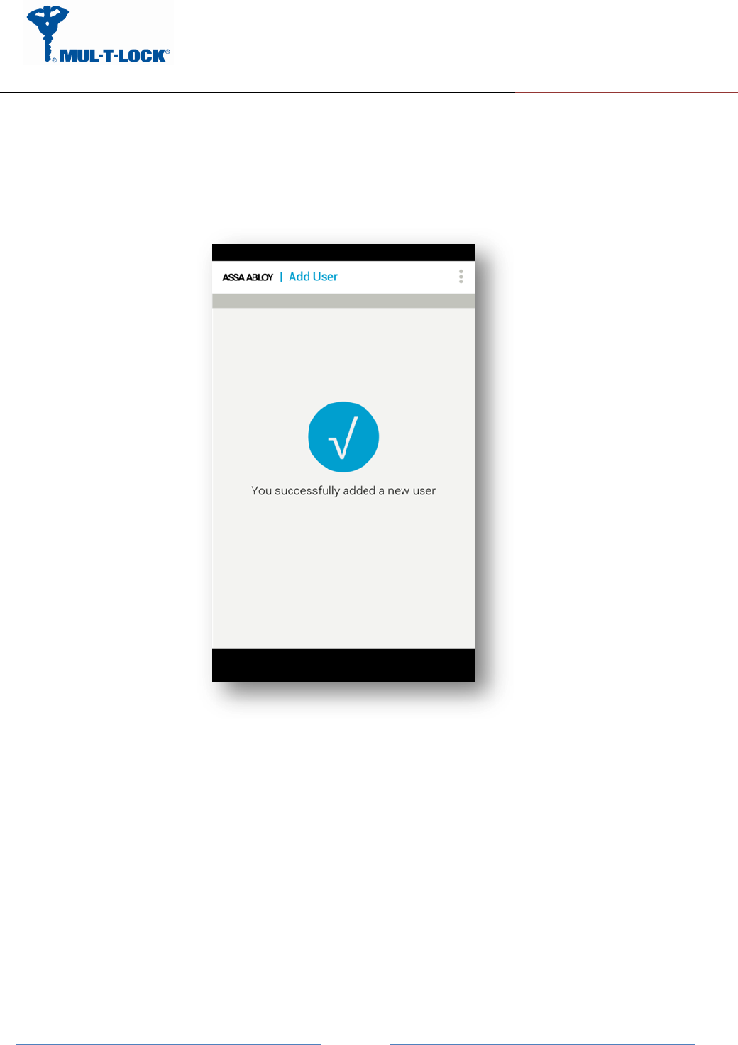
Enter the user name, generate the key code, and share or remember the code for the process
of getting the key through the Bridge unit. Press “Activate”.
ENTR Wi-Fi Bridge integration Guide
April, 24, 2017
An ASSA ABLOY Group Brand
Page
10
On Success you will see the following screen:
From this moment, for the predefined expiration time, the key will be waiting in the lock
(pending) until it will be pulled from the lock using this code. The key pulling can be done by the
Bridge.
ENTR Wi-Fi Bridge integration Guide
April, 24, 2017
An ASSA ABLOY Group Brand
Page
11
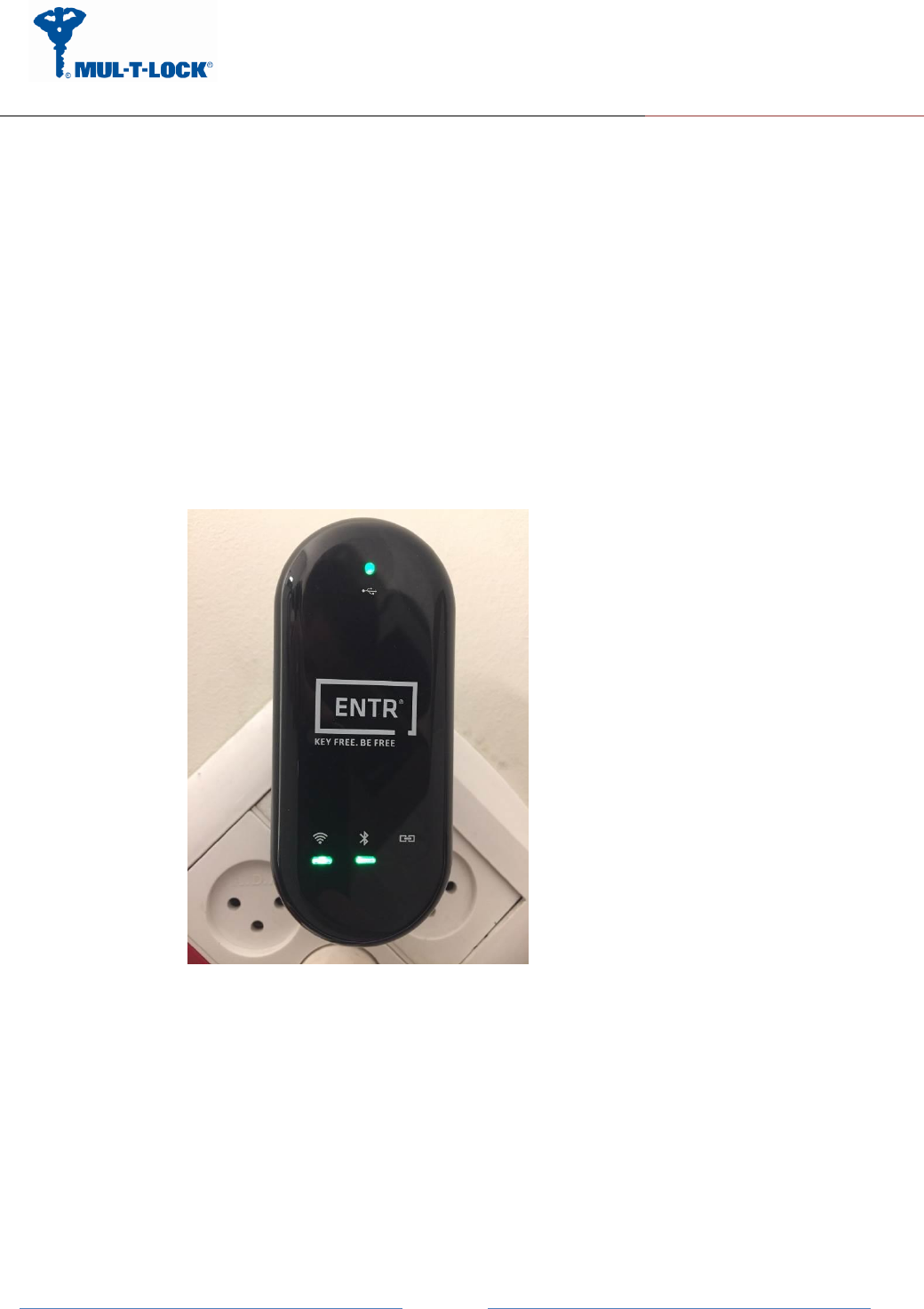
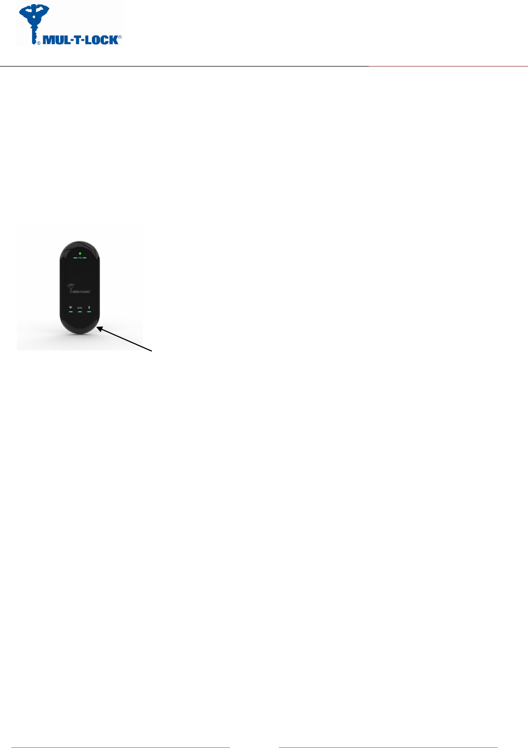
3.2 Powering up the Bridge
It is recommended that you first set up this Bridge somewhere close to the wireless router, and
then move this Bridge to another location for optimal Wi-Fi reception.
Insert the Bridge adaptor into the AC socket.
The bridge will start powering up and the green power led will become steady if the BIT
procedure passes successfully (picture 1).
The BLE pairing, server, IP or URL address procedures are done via the Configuration App. as
well.
Picture 1.
ENTR Wi-Fi Bridge integration Guide
April, 24, 2017
An ASSA ABLOY Group Brand
Page
12
3.3 Configuration the Bridge step by step
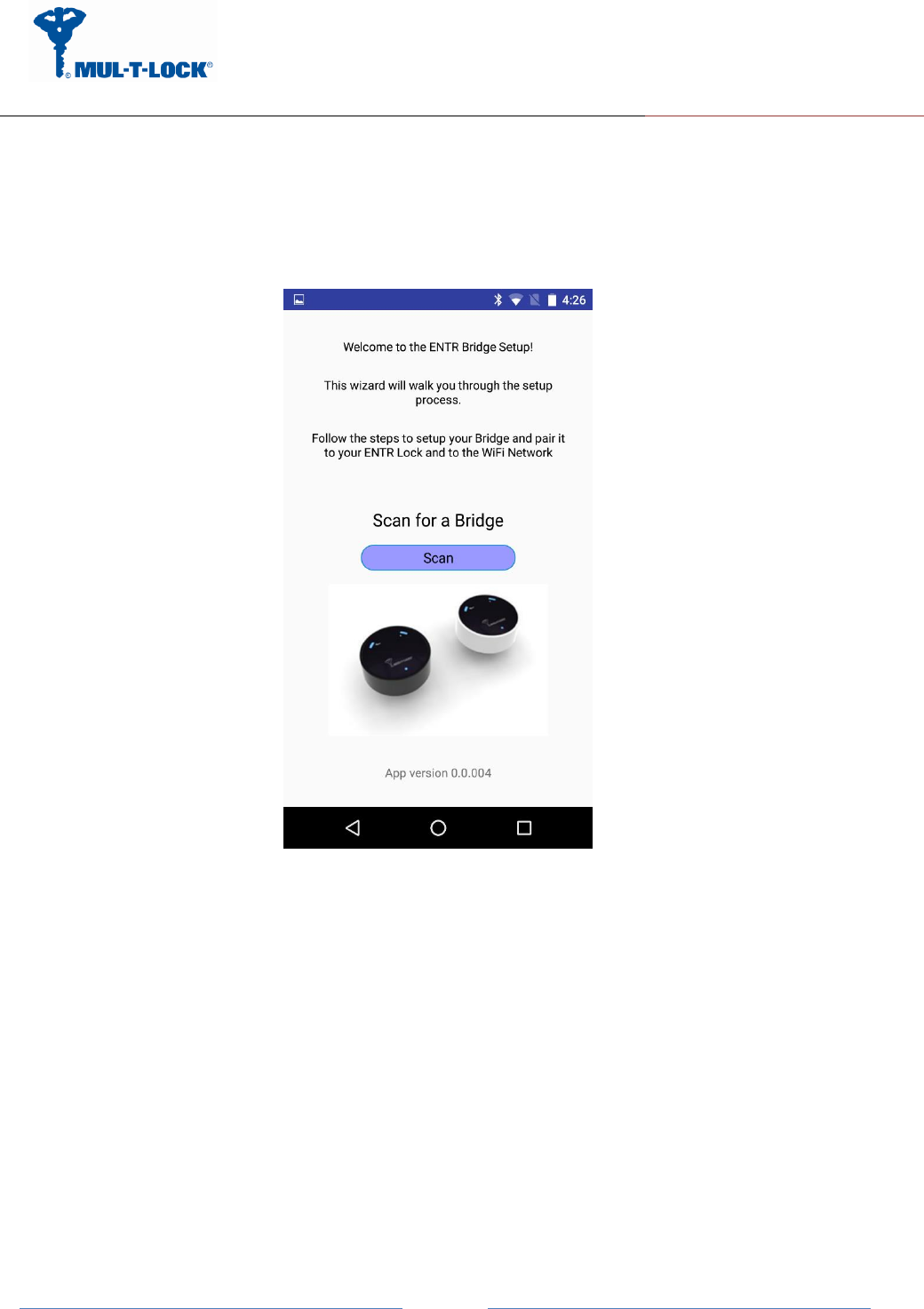
3.3.1 Configuration App. connecting to the Bridge
Open the configuration application on your mobile phone.
Picture 2.
A welcome ENTR bridge set up appears.
Now press the "Scan" button and wait for the app to connecting to the Bridge.
ENTR Wi-Fi Bridge integration Guide
April, 24, 2017
An ASSA ABLOY Group Brand
Page
13
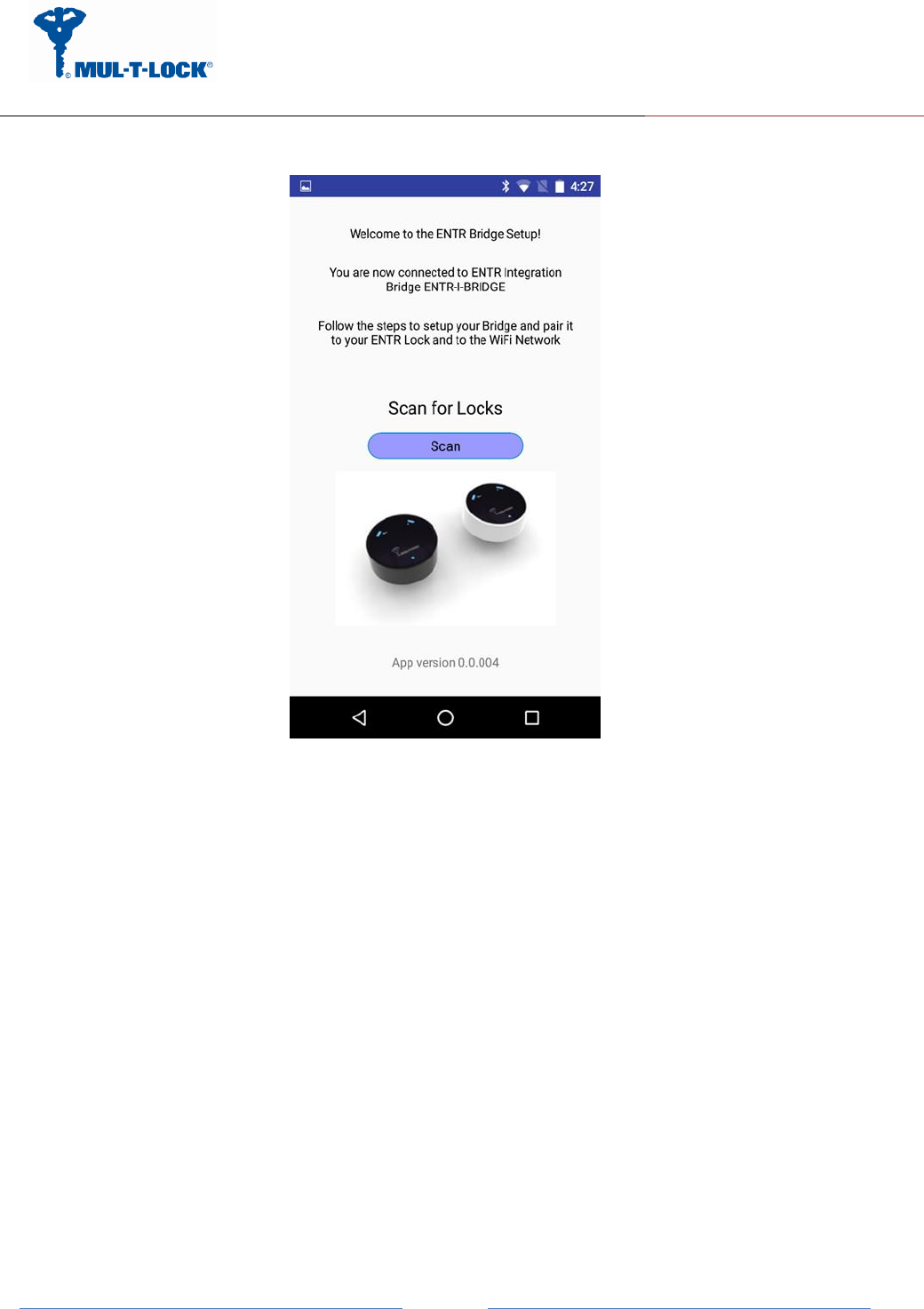
Picture 3.
After the App. is connecting to the Bridge successfully the App. updates its status to "You are
now connected to ENTR Integration Bridge ENTR-I-BRIDGE".
Remark: The same configuration application supports both integration and Tiny bridges.
3.3.2 Pairing the Bridge to the ENTR BLE domain
After adding the bridge and generating a key per paragraph 3.1 we can start paring the bridge
to the ENTR BLE domain.
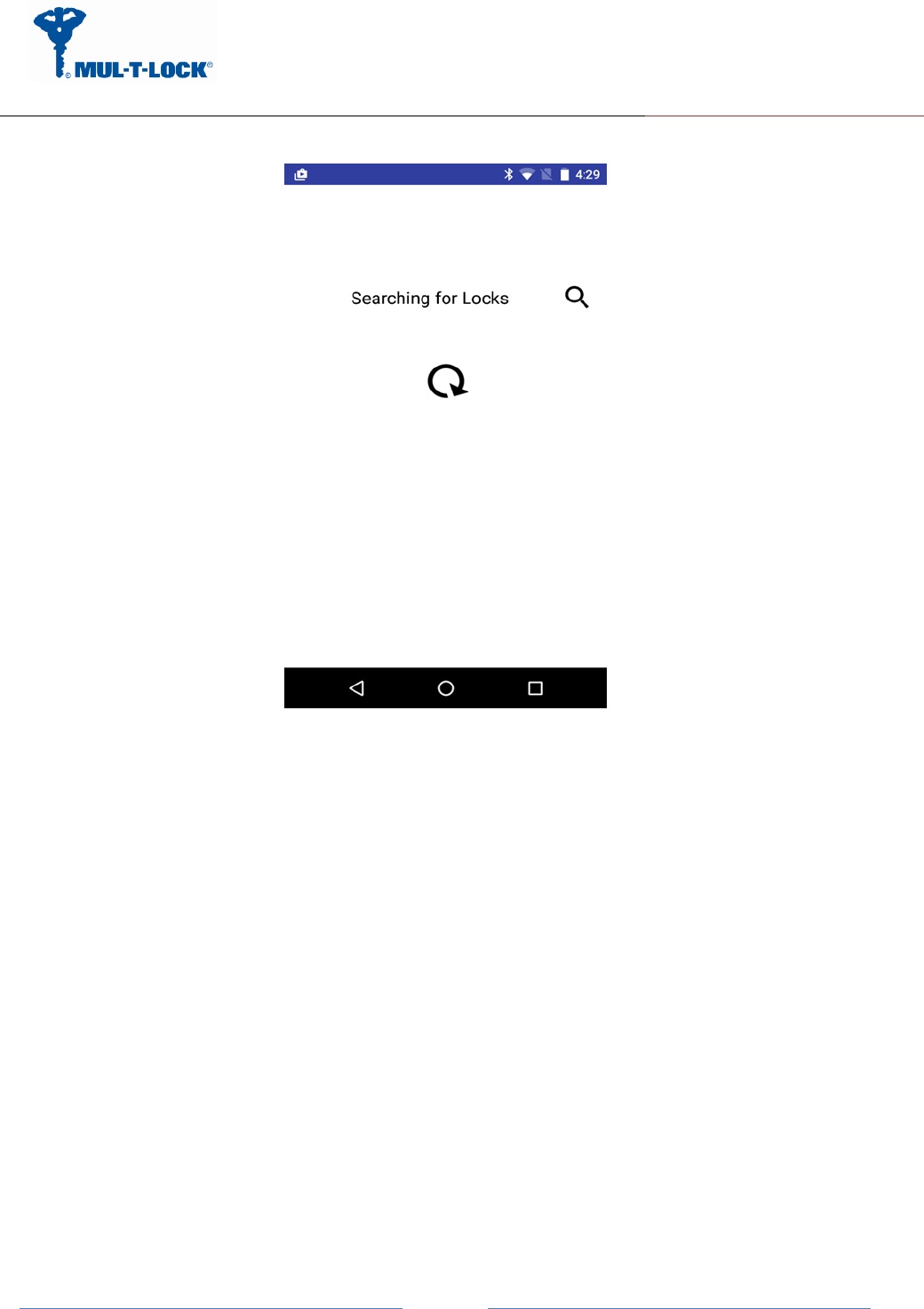
Press the scan icon (picture 3) for ENTR door locks that pending a key.
ENTR Wi-Fi Bridge integration Guide
April, 24, 2017
An ASSA ABLOY Group Brand
Page
14
Picture 4.
The App. is searching for locks that are in BLE range and have a pending key.
ENTR Wi-Fi Bridge integration Guide
April, 24, 2017
An ASSA ABLOY Group Brand
Page
15
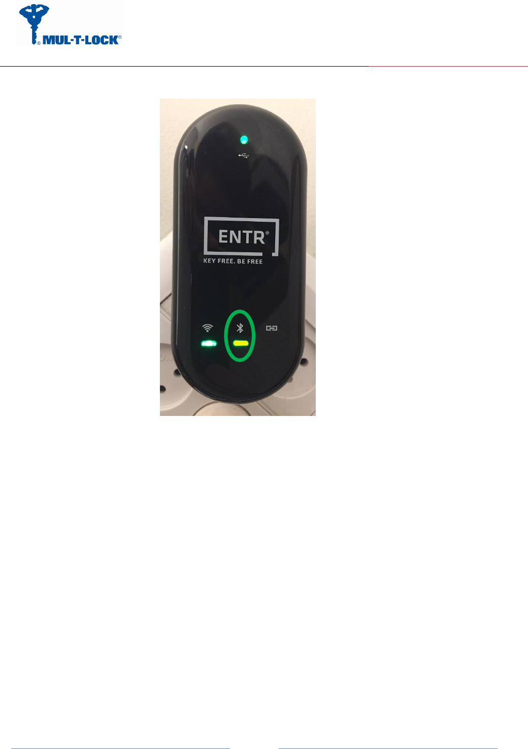
Picture 5.
The BLE LED blinks in Amber color that indicates that the bridge is searching for locks that
are within BLE range and have a pending key.
ENTR Wi-Fi Bridge integration Guide
April, 24, 2017
An ASSA ABLOY Group Brand
Page
16
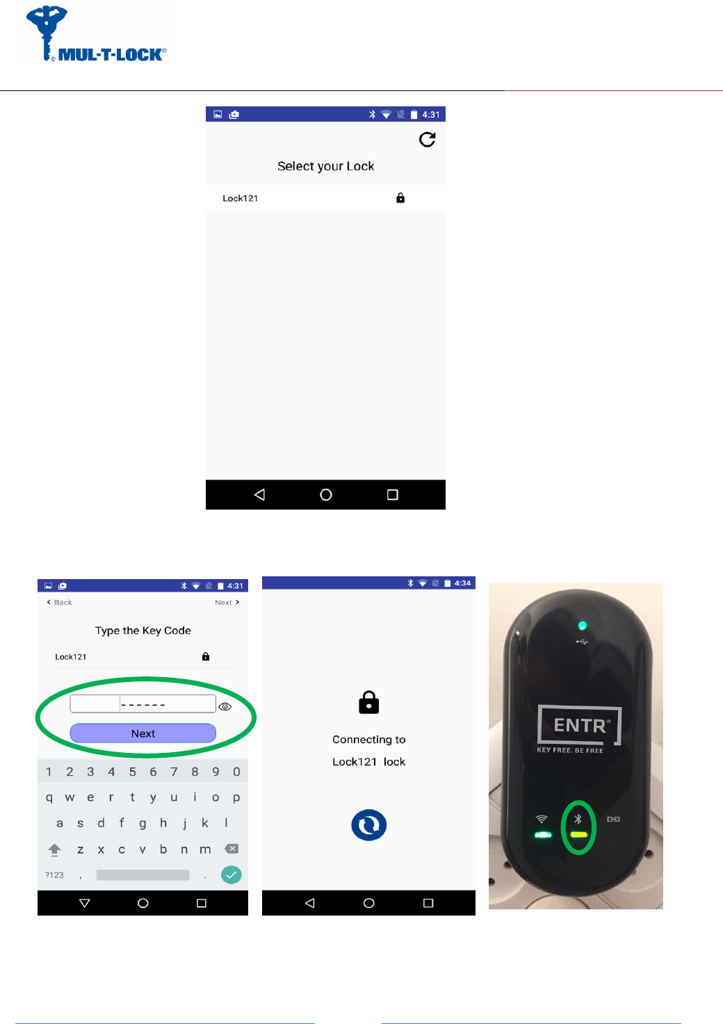
Picture 6.
Select "Lock 121" from the list appears on the screen on picture 6.
Picture 7.
ENTR Wi-Fi Bridge integration Guide
April, 24, 2017
An ASSA ABLOY Group Brand
Page
17
Type your pin code that you received per paragraph 3.1.a connecting attempt will appears
on your screen.
Wait for successful connection and ensure that the BLE LED is steady state amber colored.
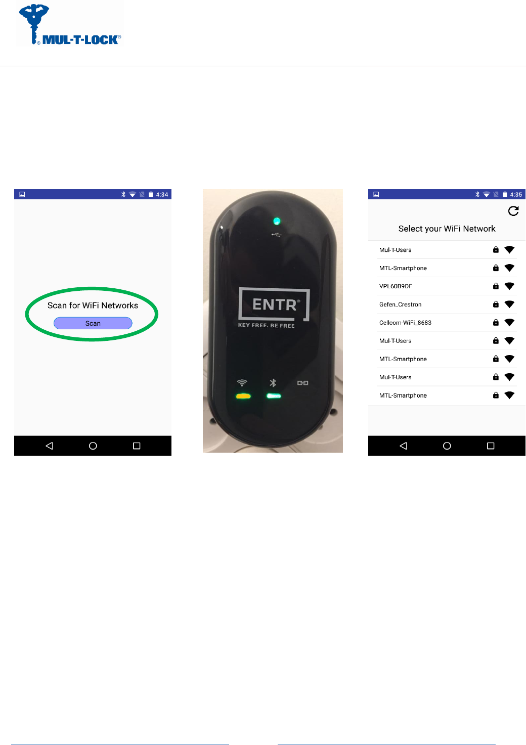
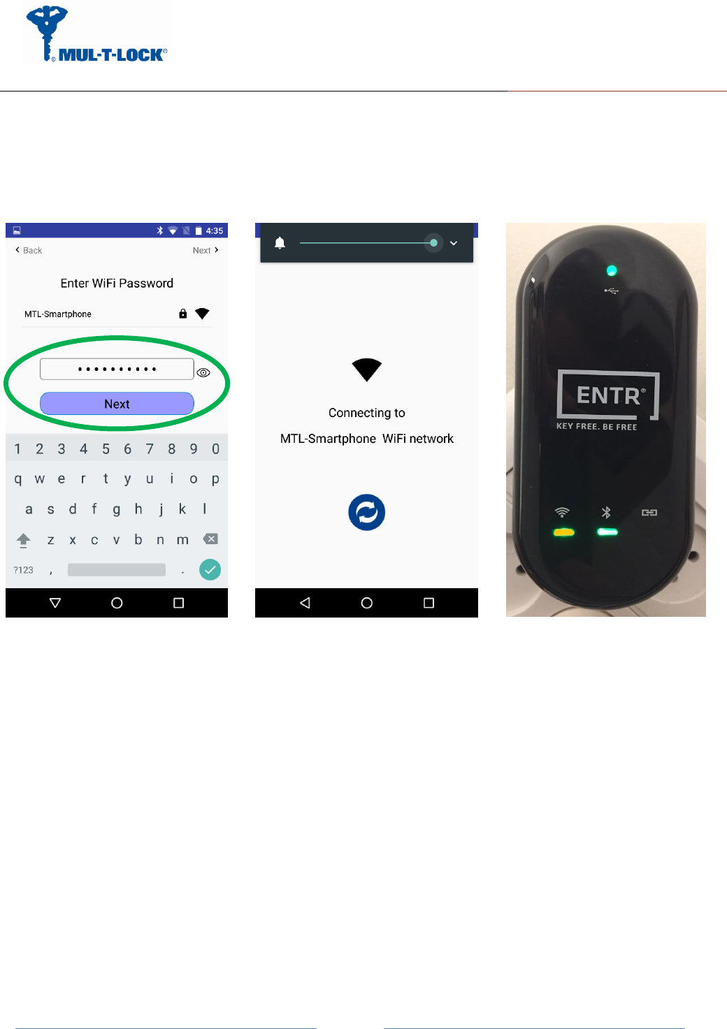
3.3.3 Pairing the Bridge to the Wi-Fi network domain
Picture 8.
Now we are ready to configure the Wi-Fi section of the bridge.
Remark: There are two methods to connect to a Wi-Fi network, one is via WPS (QSS)
procedure (see appendix A) and the other is via the configuration application.
Press the Wi-Fi scan icon in order to scan for Wi-Fi networks within Wi-Fi range (see picture
8).
ENTR Wi-Fi Bridge integration Guide
April, 24, 2017
An ASSA ABLOY Group Brand
Page
18
Picture 9.
Enter the Wi-Fi network password (SSID), a connecting attempt will appears on your screen.
The Wi-Fi LED blinks in Amber color and wait for successful connection – Wi-Fi LED become
steady state amber colored.
ENTR Wi-Fi Bridge integration Guide
April, 24, 2017
An ASSA ABLOY Group Brand
Page
19
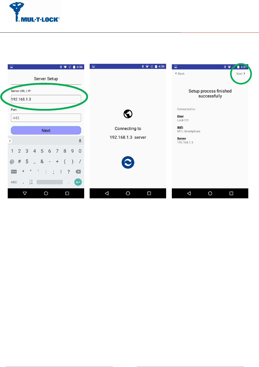
3.3.4 Bridge to server configuration procedure
The integrator has to enter the DNS server IP or URL address and port number (optional).
Default port number is 40003.
Press "Next" after filling both fields.
When setup is done, the bridge will try to connect to the server. Make sure the server is up and
running.
After the configuration is done and you get the "setup process finished successfully" screen you
should press NEXT> and just than the bridge will exist configuration mode and enter to working
mode.

ENTR Wi-Fi Bridge integration Guide
April, 24, 2017
An ASSA ABLOY Group Brand
Page
20
4. For radio enclosure
Federal Communications Commission (FCC) Statement labelling
requirement for small device statement (FCC15.19 (3))
This device complies with part 15 of the FCC Rules. Operation is subject to the following
two conditions: (1) This device may not cause harmful interference, and (2) this device must
accept any interference received, including interference that may cause undesired operation.
4.1 Radio Frequency Interference (RFI) (FCC 15.105)
This equipment has been tested and found to comply with the limits for Class B digital devices
pursuant to Part 15 of the FCC Rules. These limits are designed to provide reasonable
protection against harmful interference in a residential environment. This equipment
generates, uses, and can radiate radio frequency energy, and if not installed and used in
accordance with the instruction manual, may cause harmful interference to radio
communications. However, there is no guarantee that interference will not occur in a particular
installation. If this equipment does cause harmful interference to radio or television reception,
which can be determined by turning the equipment off and on, the user is encouraged to try
and correct the interference by one or more of the following measures:
•
Reorient or relocate the receiving antenna.
•
Increase the separation between the equipment and the receiver.
•
Connect the equipment into an outlet on a circuit different from that to which the receiver is
connected.
•
Consult the dealer or an experienced radio/TV technician for help.
4.2 Labeling Requirements (FCC 15.19)
This device complies with Part 15 of FCC rules. Operation is subject to the following two
conditions: (1) this device may not cause harmful interference, and (2) this device must accept
any interference received, including interference that may cause undesired operation.

ENTR Wi-Fi Bridge integration Guide
April, 24, 2017
An ASSA ABLOY Group Brand
Page
21
Product FCC ID: 2AHH881134
4.3 Modifications (FCC 15.21)
Changes or modifications to this equipment not expressly approved by Mul-T-Lock® may void
the user’s authority to operate this equipment.
4.4 RF Exposure info (FCC 2.1093)-for module radio
This equipment has been approved for mobile applications where the equipment should be
used at distances greater than 20cm from the human body (with the exception of hands, wrists,
feet and ankles). Operation at distances less than 20cm is strictly prohibited.
FOR MOBILE DEVICE USAGE (>20cm/low power) Radiation
Exposure Statement:
This equipment complies with ISED radiation exposure limits set forth for an uncontrolled
environment. This equipment should be installed and operated with minimum distance 20cm
between the radiator & your body.
ENTR Wi-Fi Bridge integration Guide
April, 24, 2017
An ASSA ABLOY Group Brand
Page
22
Appendix A
WPS Configuration
You can connect to the Bridge’s Wi-Fi network with Wi-Fi Protected Setup (WPS), to use WPS
procedure do the following:
Make sure that the Bridge has power (its green Power LED is lit steady).
Press the WPS button on the Bridge for 3 seconds (WPS button is located on the bottom
right of the Bridge) until the Wi-Fi white color led start blinking.
Within two minutes, on your router, press its WPS button or follow its instructions for WPS
connections, now wait for the WPS setup to end till the Wi-Fi white color led will lit steady.
Now wait that the Wi-Fi amber led will lit steady (white color led will turn off) to indicate the
bridge join the network successfully ,If the WPS configuration fails the white led will turn off
and a solid red led will lit to indicate that the Bridge fails to join the network.
If the WPS procedure fails or the wireless router does not support WPS procedure go to
paragraph 3.3.3.