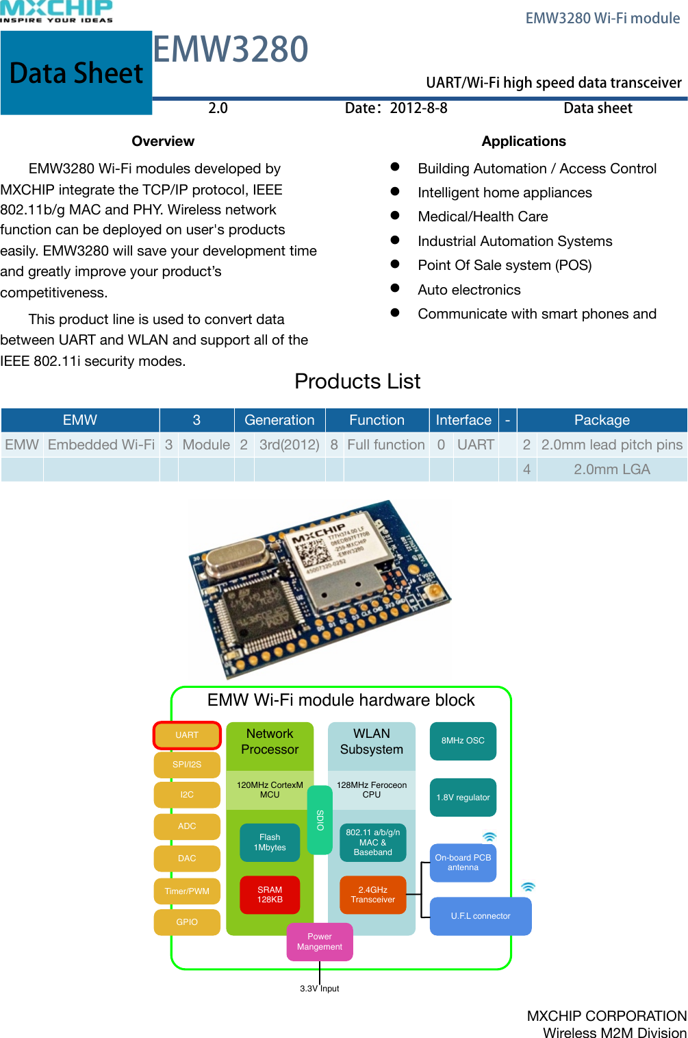
MXCHIP Information Technology EMW3280 Wi-Fi Module User Manual DS0001E EMW3280 V2

Shanghai MXCHIP Information Technology Co.,Ltd. Wi-Fi Module DS0001E EMW3280 V2

P53-EMW3280_User Manual

Data SheetEMW3280EMW3280Data SheetUART/Wi-Fi high speed data transceiverUART/Wi-Fi high speed data transceiverData Sheet2.0Date:2012-8-8Data sheetOverviewEMW3280 Wi-Fi modules developed by MXCHIP integrate the TCP/IP protocol, IEEE 802.11b/g MAC and PHY. Wireless network function can be deployed on user's products easily. EMW3280 will save your development time and greatly improve your product’s competitiveness.This product line is used to convert data between UART and WLAN and support all of the IEEE 802.11i security modes.ApplicationsBuilding Automation / Access Control Intelligent home appliancesMedical/Health Care Industrial Automation SystemsPoint Of Sale system (POS) Auto electronicsCommunicate with smart phones andProducts ListEMW EMW 33GenerationGenerationFunctionFunctionInterfaceInterface-PackagePackageEMWEmbedded Wi-Fi3Module23rd(2012)8Full function0UART22.0mm lead pitch pins42.0mm LGA! EMW Wi-Fi module hardware blockNetworkProcessor120MHz CortexM MCUFlash1MbytesSRAM128KBWLANSubsystem128MHz Feroceon CPU802.11 a/b/g/n MAC & Baseband2.4GHz TransceiverOn-board PCB antennaU.F.L connector8MHz OSC1.8V regulator     PRODUCT BRIEF  GS1011 Ultra Low-Power Wireless Single Chip PRODUCT OVERVIEW GS1011  device  is  a  highly  integrated  ultra  low  power  wireless  single  chip  whichcontains an 802.11 radio, media access controller (MAC) and baseband processor,on-chip  flash  memory  and  SRAM,  and  an  applications  processor  all  on  a  singlepackage.  The  GS1011  supports  the  full  802.11b  (11Mbps)  data  rates  providing scalability on data  throughput for  higher  bandwidth  application  while  still  providingthe  ultra  low  power consumption  for  years  of  battery  life.  The  GS1011  is  pin  and package  compatible  with  the  GS1010  enabling  seamless  hardware  upgrade  forcurrent designs. Along with its embedded software stack it offers a highly scalable,reliable,  manageable  and  secure  wireless  link  to  meet  the  growing  demand  of wireless  sensor  networks  utilizing  the  broadly  accepted  IEEE  802.11  standardsinfrastructure.  This  solution  is  ideal  for  use  in  smart  energy,  building  automation,industrial and commercial  automation  and  cold  storage  monitoring  applications.  In addition, the  solution  provides  capabilities such as  location  awareness  which alsomake  it  well  suited  for  logistics  and  supply  chain  applications  for  tracking  assetlocation and status. FEATURES & BENEFITS  Highly Integrated wireless SOC with 802.11 radio, MAC and Baseband, Integrated PA, Application CPU, RTC, SRAM and FLASH   Reduces system cost of implementing separate devices and lowers design complexity   Ultra small form-factor reduces board space  Supports IEEE 802.11   Lowers customer’s total cost of ownership (TCO) in network implementation and  management    Seamlessly integrates with existing 802.11b/g infrastructure and utilizes the 802.11 security, manageability, easeof-use, and quality of service   Supports full 802.11b data rates (up to 11 Mbps) for higher bandwidth applications       802.11i/WPA2 Authentication, AES Hardware encryption   Enterprise level security &reliability for sensor networks  Power Management   Optimized for battery powered application  with very low power consumption for multiple years of battery life  Location Awareness   Enables users to trace and monitor assets   Multiple I/O: SPI, UART, PWM, I2C, ADC, GPIO   Provides flexibility in system design for  easier integration  Firmware, Device drivers, Reference Application SW, APIs, and SDK   Reduces customer development time for  application software enabling faster time to market  Seamless HW upgrade to current designs   Pin and package compatible with GS1010,  makes it drop in replacement onto current GS1010 designs    GS1011 BLOCK DIAGRAM Standby Power DomainNetworkProcessorWLANSubsystemUARTAntennaExternal Power Amp Control (Optional) RF Switch44MHz XTALDC-DC Control2x External Wake Up32kHz XTAL2x SPI2x UART2x ADCI2C3x PWM32x GPIO ARM7 CPUBattery (3.6V – 1.2V)SPIADCI2CPWMGPIOARM7 CPU2.4 GHzTransceiver802.11MAC &BasebandFlash256KBSRAM128KBRTC2x AlarmXTLOSC1.8 V RegulatorNVRAM512 Bytes     PRODUCT BRIEF  GS1011 Ultra Low-Power Wireless Single Chip PRODUCT OVERVIEW GS1011  device  is  a  highly  integrated  ultra  low  power  wireless  single  chip  whichcontains an 802.11 radio, media access controller (MAC) and baseband processor,on-chip  flash  memory  and  SRAM,  and  an  applications  processor  all  on  a  singlepackage.  The  GS1011  supports  the  full  802.11b  (11Mbps)  data  rates  providing scalability on data  throughput for  higher  bandwidth  application  while  still  providingthe  ultra  low  power consumption  for  years  of  battery  life.  The  GS1011  is  pin  and package  compatible  with  the  GS1010  enabling  seamless  hardware  upgrade  forcurrent designs. Along with its embedded software stack it offers a highly scalable,reliable,  manageable  and  secure  wireless  link  to  meet  the  growing  demand  of wireless  sensor  networks  utilizing  the  broadly  accepted  IEEE  802.11  standardsinfrastructure.  This  solution  is  ideal  for  use  in  smart  energy,  building  automation,industrial and commercial  automation  and  cold  storage  monitoring  applications.  In addition, the  solution  provides  capabilities such as  location  awareness  which alsomake  it  well  suited  for  logistics  and  supply  chain  applications  for  tracking  assetlocation and status. FEATURES & BENEFITS  Highly Integrated wireless SOC with 802.11 radio, MAC and Baseband, Integrated PA, Application CPU, RTC, SRAM and FLASH   Reduces system cost of implementing separate devices and lowers design complexity   Ultra small form-factor reduces board space  Supports IEEE 802.11   Lowers customer’s total cost of ownership (TCO) in network implementation and  management    Seamlessly integrates with existing 802.11b/g infrastructure and utilizes the 802.11 security, manageability, easeof-use, and quality of service   Supports full 802.11b data rates (up to 11 Mbps) for higher bandwidth applications       802.11i/WPA2 Authentication, AES Hardware encryption   Enterprise level security &reliability for sensor networks  Power Management   Optimized for battery powered application  with very low power consumption for multiple years of battery life  Location Awareness   Enables users to trace and monitor assets   Multiple I/O: SPI, UART, PWM, I2C, ADC, GPIO   Provides flexibility in system design for  easier integration  Firmware, Device drivers, Reference Application SW, APIs, and SDK   Reduces customer development time for  application software enabling faster time to market  Seamless HW upgrade to current designs   Pin and package compatible with GS1010,  makes it drop in replacement onto current GS1010 designs    GS1011 BLOCK DIAGRAM Standby Power DomainNetworkProcessorWLANSubsystemUARTAntennaExternal Power Amp Control (Optional) RF Switch44MHz XTALDC-DC Control2x External Wake Up32kHz XTAL2x SPI2x UART2x ADCI2C3x PWM32x GPIO ARM7 CPUBattery (3.6V – 1.2V)SPIADCI2CPWMGPIOARM7 CPU2.4 GHzTransceiver802.11MAC &BasebandFlash256KBSRAM128KBRTC2x AlarmXTLOSC1.8 V RegulatorNVRAM512 Bytes3.3V InputUARTSPI/I2SADCDACTimer/PWMI2CGPIOSDIO Power MangementMXCHIP CORPORATIONWireless M2M Division    EMW3280 Wi-Fi module
FeaturesFast, ease of use embedded system interfaceUART baudrate is up to 921600Max. data transmission speed: 90kbytes/s (UART)Support UART hardware flow control which ensure reliable data transmission in high speed modeSimplified hardware connectionsSecure, stable Wi-Fi linkSupport AP chient mode, soft AP mode and Ad-hoc modeSecure, stable Wi-Fi linkAuto recover from Wi-Fi’s disconnectionSupport WPA/WPA2 PSK, WEP encryptionIPEX antenna connector, on board PCB antennaCE,FCC passedEmbedded TCP/IP stackSupport UDP protocol, broadcast and unicastSupport TCP protocol, act as TCP server or clientAllow 3 connections from TCP client under TCP server modeAuto reconnect after TCP link is lostTransfer data to internet through a gatewaySupport DNS serviceFlexible configuration and managementUse EMSP commands to control and config module through UARTSend EMSP commands from Wi-Fi networkConfiguration on build-in html pagesConfiguration software is provided on multiple platformsDesigned for embedded systemsLess than 220mA in running modeLess than 1mA in standby modeLess than 30mA in low power mode, network connection is maintainedTime interval from reset to Wi-Fi connection is less than 2 seconds  Reliable quality, comprehensive technical servicesIndustrial temperature range: -40󺔯80℃Module test appliance is providedROSH certification passedEvaluation boards, API library and test source codes are provided    EMW3280 Wi-Fi module
󲥣录1. Function Description!11.1.Features!1RF features!1UART features !1TCP/IP features !11.2.Electrical Parameters!21.2.1.Absolute maximum ratings: Voltage & Current!21.2.2.Operating conditions: Voltage & Current!21.2.3.Digital I/O port characteristics!3Output voltage levels!3Output voltage levels!3NRST pin characteristics !31.2.4.Absolute maximum ratings: Temperature!31.2.5.Absolute maximum ratings: The Electromagnetic Environment Electrostatic discharge (ESD)!31.2.6.Static latch-up!41.2.7.RF characteristics !51.3.Mechanical Dimensions!91.3.1.Mechanical Dimensions Of EMW3280 (Metric units)!92. Module interface!102.1.Leds!102.2.Pinouts!102.3.Pin Arrangement!112.4.Typical Hardware Connection And Pin Description!113. Antenna!143.1.Minimizing radio interference!143.2.On-board Antenna Specification!143.3.U.F.L RF Connector!154. Lable!165. Recommended Reflow Profile!176. MSL/Storage Condition!177. Sales Information!18    EMW3280 Wi-Fi module
8. Technical Support!18    EMW3280 Wi-Fi module
1. Function DescriptionEMW3280 Wi-Fi modules developed by MXCHIP integrate the TCP/IP protocol, IEEE 802.11b/g MAC and PHY. Wireless network function can be deployed on user's products easily. EMW3280 will save your development time and greatly improve your product’s competitiveness.EMW3280 modules can run in the industrial temperature rang: -40℃ to 85℃. The highest baudrate of UART interface is 921600. It has two transfer modes: TCP, UDP, and support EMSP commands to configure its parameters.1.1. Features★Single operation voltage: 3.3V. ★Power consumption: <220mA under run mode, current <1mA under standby mode.★CPU frequency: 120MHz,flash size: 1M bytes,RAM size128k bytes.★Two working modes: command mode and data transmission mode.★Complete Wi-Fi wireless communications solutions, to reduce the resource requirements of the application processor;★Multipul configuration methods: build-in web pages,EMW tool box(PC software) and EMSP commands;RF features★WLAN standard: IEEE 802.11b/g/n, Wi-Fi compatible.★RF frequency: 2.4G ISM. ★Support AP chient mode, soft AP mode and Ad-hoc mode.★WEP40 and WEP104 encryption (64/128bit), support open system or shared key.★WPA/WPA2 PSK encryption, use AES or TKIP encryption algorithm.★Auto recover from Wi-Fi disconnection.★Time interval from reset to Wi-Fi connection is less than 2 seconds.UART features★UART Baudrate:1200-921600;★Highest transmission speed: 90kbytes/s(send or receive), 60kbytes/s(send & receive both). ★upport UART hardware flow control that provide the reliable data transmission TCP/IP features★Support DNS service.★Support DHCP client and DHCP server.★Support network data transmission protocol: TCP, UDP;★TCP server or client.★Reliable TCP link management: Automatic reconnect when the connection was lost.★As a TCP server, allow 3 TCP connection from the clients.★UDP broadcast or unicast.! ! EMW3280 Wi-Fi module1
1.2. Electrical Parameters1.2.1. Absolute maximum ratings: Voltage & CurrentStresses above the absolute maximum ratings may cause permanent damage to the device. These are stress ratings only and functional operation of the device at these conditions is not implied. Exposure to maximum rating conditions for extended periods may affect device reliability. SymbolRatingsMinMaxUnitVDD–VSSVoltage–0.34.0VVINInput voltage on five volt tolerant pinVSS −0.35.5VVINInput voltage on any other pinVSS −0.3VDD+0.3VSymbolRatingsMaxUnitIVDDTotal current into VDD power lines (source)320mA IVSSTotal current out of VSS ground lines (sink)320mA IIOOutput current sunk by any I/O and control pin25mA IIOOutput current source by any I/Os and control pin-25mA 1.2.2. Operating conditions: Voltage & CurrentSymbolNoteConditionsSpecificationSpecificationSpecificationSpecificationSymbolNoteConditionsMin.TypicalMax.UnitDDIVDDCurrentVDD=3.3V, normal2437 MHz,18 dBm,11 Mbps CCKTX Speed:80kbytes/s219224230mAIVDDCurrentVDD=3.3V, normal2437 MHz,18 dBm,11 Mbps CCKTX Speed:10kbytes/s199202204mAIVDDCurrentVDD=3.3V, normal2437 MHz,15 dBm,54 Mbps OFDMTX Speed:80kbytes/s203204205mAIVDDCurrentVDD=3.3V, normal2437 MHz,15 dBm,54 Mbps OFDMTX Speed:10kbytes/s199200202mAIVDDCurrentVDD=3.3V,Receive mode182185188mAIVDDCurrentVDD=3.3V,Sleep mode5060uA! ! EMW3280 Wi-Fi module2VVoltage 3.0 3.3 3.5 V
1.2.3. Digital I/O port characteristicsOutput voltage levelsSymbolNoteParameterConditionsMin.Max.UnitVOLUART & IO output voltageOutput low level voltageIIO = +8 mA2.7 V < VDD < 3.6 V0.4VVOHUART & IO output voltageOutput high level voltageIIO = +8 mA2.7 V < VDD < 3.6 VVDD-0.4VVOLUART & IO output voltageOutput low level voltageIIO = +20 mA2.7 V < VDD < 3.6 V1.3VVOHUART & IO output voltageOutput high level voltageIIO = +20 mA2.7 V < VDD < 3.6 VVDD-1.3VOutput voltage levelsSymbolNoteParameterConditionsMin.Max.UnitVILUART & IO input voltageInput low level voltageTTL level-0.50.8VVIHUART & IO input voltageInput high level voltageTTL level2VDD+0.5VVIHUART & IO input voltageInput high level voltage(5V input tolerant)TTL level25.5VVILUART & IO input voltageInput low level voltageCMOS level-0.50.35VDDVVIHUART & IO input voltageInput high level voltageCMOS level0.65VDDVDD+0.5VNRST pin characteristicsThe NRST pin input driver uses CMOS technology. EMW3280 contains RC(resistance-capacitance) reset circuit which ensures the module reset accurately when it powers up. If you need to reset manually, just connect the external control signals to the reset pins directly. Additional, you can also control the reset by means of the EMSP command.SymbolItemConditionsMin.TypicalMax.UnitVIL(NRST)/RESET input low level–0.50.8VVIH(NRST)/RESET input high level2VDD+0.5VRPUResistor for Pulling up VIN = VSS7.588.3kΩCPDCapacitor for charging and Resetting  1001000pF1.2.4. Absolute maximum ratings: TemperatureSymbolRatingsMaxUnitTSTGStorage temperature–55 to +125℃TAWorking temperature-40 to +85℃1.2.5. Absolute maximum ratings: The Electromagnetic Environment Electrostatic discharge (ESD)SymbolRatingsConditionsClassMaxUnitVESD(HBM)Electrostatic discharge voltage (human body model)TA = +25 °C conforming to JESD22-A11422000V! ! EMW3280 Wi-Fi module3
SymbolRatingsConditionsClassMaxUnitVESD(CDM)Electrostatic discharge voltage (charge device model)TA = +25 °C conforming to JESD22-C101II500V1.2.6. Static latch-upThese tests are compliant with EIA/JESD 78A IC latch-up standard.SymbolParameterClassClassLUStatic latch-up class TA = +105 °C conforming to JESD78A II level A ! ! EMW3280 Wi-Fi module4
1.2.7. RF characteristicsBasic characteristicsItem SpecificationOperating Frequency 2.412~2.472GHzWiFi Standard 802.11b/g/n(1x1)*Modulation Type11b: DBPSK, DQPSK,CCK for DSSS11g: BPSK, QPSK, 16QAM, 64QAM for OFDM11n: MCS0~7,OFDM*Data Rates11b:1, 2, 5.5 and 11Mbps11g:6, 9, 12, 18, 24, 36, 48 and 54 Mbps11n: MCS0~7, up to 150MbpsAntenna type One U.F.L connector for external antennaPCB printed ANT (Reserve)IEEE802.11b modeItem SpecificationModulation Type DSSS / CCKFrequency range 2400MHz~2483.5MHzChannel CH1 to CH13Data rate 1, 2, 5.5, 11MbpsTX Characteristics Min. Typical Max. UnitTransmitter Output PowerTransmitter Output PowerTransmitter Output PowerTransmitter Output PowerTransmitter Output Power11b Target Power 16 18 dBmSpectrum Mask @ target powerSpectrum Mask @ target powerSpectrum Mask @ target powerSpectrum Mask @ target powerSpectrum Mask @ target powerfc +/-11MHz to +/-22MHz -30 dBrfc > +/-22MHz -50 dBrFrequency Error -25 -1 +25 ppmConstellation Error( peak EVM)@ target powerConstellation Error( peak EVM)@ target powerConstellation Error( peak EVM)@ target powerConstellation Error( peak EVM)@ target powerConstellation Error( peak EVM)@ target power1~11Mbps 35%RX Characteristics Min. Typical Max. UnitMinimum Input Level SensitivityMinimum Input Level SensitivityMinimum Input Level SensitivityMinimum Input Level SensitivityMinimum Input Level Sensitivity1Mbps (FER≦8%) -97 -83 dBm2Mbps (FER≦8%) -93 -80 dBm5.5Mbps (FER≦8%) -91 -79 dBm11Mbps (FER≦8%) -89 -76 dBmMaximum Input Level (FER≦8%) -10 dBm! ! EMW3280 Wi-Fi module525<
IEEE802.11g modeItem SpecificationModulation Type OFDMFrequency range 2400MHz~2483.5MHzChannel CH1 to CH13Data rate 6, 9, 12, 18, 24, 36, 48, 54MbpsTX Characteristics Min. Typical Max. UnitTransmitter Output PowerTransmitter Output PowerTransmitter Output PowerTransmitter Output PowerTransmitter Output Power11g Target Power 13 15 dBmSpectrum Mask @ target powerSpectrum Mask @ target powerSpectrum Mask @ target powerSpectrum Mask @ target powerSpectrum Mask @ target powerfc +/-11MHz -20 dBrfc +/-20MHz -28 dBrfc > +/-30MHz -40 dBrFrequency Error -25 -1.1 +25 ppmConstellation Error( peak EVM)@ target powerConstellation Error( peak EVM)@ target powerConstellation Error( peak EVM)@ target powerConstellation Error( peak EVM)@ target powerConstellation Error( peak EVM)@ target power6Mbps -5 dBm9Mbps -8 dBm12Mbps -10 dBm18Mbps -13 dBm24Mbps -16 dBm36Mbps -19 dBm48Mbps -22 dBm54Mbps -30 -25 dBmRX Characteristics Min. Typical Max. UnitMinimum Input Level SensitivityMinimum Input Level SensitivityMinimum Input Level SensitivityMinimum Input Level SensitivityMinimum Input Level Sensitivity6Mbps (FER≦10%) -90 -82 dBm9Mbps (FER≦10%) -88 -87 dBm12Mbps (FER≦10%) -86 -79 dBm18Mbps (FER≦10%) -85 -77 dBm24Mbps (FER≦10%) -82 -74 dBm36Mbps (FER≦10%) -79 -70 dBm48Mbps (FER≦10%) -75 -66 dBm54Mbps (FER≦10%) -72 -65 dBmMaximum Input Level (FER≦10%) -20 dBm! ! EMW3280 Wi-Fi module625<
IEEE802.11n 20MHz bandwidth modeItem SpecificationModulation Type MIMO-OFDMChannel CH1 to CH13Data rate MCS0/1/2/3/4/5/6/7TX Characteristics Min. Typical Max. UnitTransmitter Output PowerTransmitter Output PowerTransmitter Output PowerTransmitter Output PowerTransmitter Output Power11n HT20 Target Power 13 15 dBmSpectrum Mask @ target powerSpectrum Mask @ target powerSpectrum Mask @ target powerSpectrum Mask @ target powerSpectrum Mask @ target powerfc +/-11MHz -20 dBrfc +/-20MHz -28 dBrfc > +/-30MHz -45 dBrFrequency Error -25 -1.2 +25 ppmConstellation Error( peak EVM)@ target powerConstellation Error( peak EVM)@ target powerConstellation Error( peak EVM)@ target powerConstellation Error( peak EVM)@ target powerConstellation Error( peak EVM)@ target powerMCS0 -5 dBmMCS1 -10 dBmMCS2 -13 dBmMCS3 -16 dBmMCS4 -19 dBmMCS5 -22 dBmMCS6 -25 dBmMCS7 -32 -28 dBmRX Characteristics Min. Typical Max. UnitMinimum Input Level SensitivityMinimum Input Level SensitivityMinimum Input Level SensitivityMinimum Input Level SensitivityMinimum Input Level SensitivityMCS0 (FER≦10%) -89 -82 dBmMCS1 (FER≦10%) -86 -79 dBmMCS2 (FER≦10%) -84 -77 dBmMCS3 (FER≦10%) -82 -74 dBmMCS4 (FER≦10%) -78 -70 dBmMCS5 (FER≦10%) -74 -66 dBmMCS6 (FER≦10%) -72 -65 dBmMCS7 (FER≦10%) -69 -64 dBmMaximum Input Level (FER≦10%) -20 dBm! ! EMW3280 Wi-Fi module7<25
IEEE802.11n 40MHz bandwidth modeItem SpecificationModulation Type MIMO-OFDMChannel CH3 to CH11Data rate MCS0/1/2/3/4/5/6/7TX Characteristics Min. Typical Max. UnitTransmitter Output PowerTransmitter Output PowerTransmitter Output PowerTransmitter Output PowerTransmitter Output Power11n HT20 Target Power 12 14 dBmSpectrum Mask @ target powerSpectrum Mask @ target powerSpectrum Mask @ target powerSpectrum Mask @ target powerSpectrum Mask @ target powerfc +/-22MHz -20 dBrfc +/-40MHz -28 dBrfc > +/-60MHz -45 dBrFrequency Error -25 -1.3 +25 ppmConstellation Error( peak EVM)@ target powerConstellation Error( peak EVM)@ target powerConstellation Error( peak EVM)@ target powerConstellation Error( peak EVM)@ target powerConstellation Error( peak EVM)@ target powerMCS0 -5 dBmMCS1 -10 dBmMCS2 -13 dBmMCS3 -16 dBmMCS4 -19 dBmMCS5 -22 dBmMCS6 -25 dBmMCS7 -31 -28 dBmRX Characteristics Min. Typical Max. UnitMinimum Input Level SensitivityMinimum Input Level SensitivityMinimum Input Level SensitivityMinimum Input Level SensitivityMinimum Input Level SensitivityMCS0 (FER≦10%) -87 -79 dBmMCS1 (FER≦10%) -84 -76 dBmMCS2 (FER≦10%) -81 -74 dBmMCS3 (FER≦10%) -79 -71 dBmMCS4 (FER≦10%) -75 -67 dBmMCS5 (FER≦10%) -71 -63 dBmMCS6 (FER≦10%) -69 -62 dBmMCS7 (FER≦10%) -66 -61 dBmMaximum Input Level (FER≦10%) -20 dBm! ! EMW3280 Wi-Fi module825<
1.3. Mechanical Dimensions1.3.1. Mechanical Dimensions Of EMW3280 (Metric units) !! Figure 1.1 EMW3280 top view Figure 1.2 EMW3280 side viewFigure 1.3 EMW3280 bottom view! ! EMW3280 Wi-Fi module9
2. Module interface2.1. Leds D1D2Table 2.1 LED functionsNameColorDescriptionD1GreenOn: Initialize successful, working in normalOff:Initialize failed, or standby modeFlashing (Short/short/short): Firmware update modeFlashing (Short/long/short): Illegal firmware versionD2RedFlashing: Data transmission (test failed in MFG mode)On:Wi-Fi is connectedOff:Wi-Fi disconnected2.2. Pinouts EMW3280has two groups of pins (1X15 +1X15). The lead pitch is 2mm.EMW3280’s pinout is shown in the Figure 2.1. Table 2.2 lists the pin functions.Figure2.1 EMW3280: appearance and pinout! ! EMW3280 Wi-Fi module10
2.3. Pin Arrangement Figure 2.2 EMW3280 pin arrangementPinsPin NameFTPinsPin NameFT1-14NC22UART_TXD(OUT)15GND23UART_RXD(IN)√16nWI-FI LED(OUT)BOOT(IN)24VDD17nRESET(IN)25GND18IO126-28NC19NC29nWAKE_UP(IN)20nUART_RTS(OUT)30STATUS(IN)√21nUART_CTS(IN)√2.4. Typical Hardware Connection And Pin Description EMW3280 consume more power in data transmission. It is recommended that the VDD power supply is connected in parallel with a 330uF/5V solid capacitor, or a high-frequency electrolytic capacitor (low ESR), this can reduce the requirements of DC power supply, A 300mA LDO can be used (500mA LDO is recommended).Host DeviceUART TXUART RXIO circultWI-Fi ModuleUART TXIO circultUART RXTXnCTSUART_RXDnUART_RTSRXnRTSUART_TXDnUART_CTSIO2IO1IO3STATUSnRESETWAKEUPOptionalOptionalOptionalOptionalOptional3.3VOptionalnWIFI LED/BOOT3.3V VDDGND1KIO4 FC(IO1)Optional Figure 2.3 Typical hardware connection: TTL/CMOS UART Interface ! ! EMW3280 Wi-Fi module11
Host DeviceRS232 TXRS232 RXIO circultWI-Fi ModuleTX circultIO circultRX circultTXnCTSUART_RXDnUART_RTSRXnRTSUART_TXDnUART_CTSIO2IO1IO3STATUSnRESETWAKEUPOptionalOptionalOptionalOptionalOptional3.3VOptionalnWIFI LED/BOOTGND1KMAX3232C1+C1-C2+C2-VccV+V-13453.3V162614 T1OUT T1IN 11R1IN R1OUT13 12T2OUT T2INR2IN R2OUT71089IO3 FC(IO1)Optional3.3V VDDFigure 2.4 Typical hardware connection: RS232 UART InterfaceMAX34853.3VVCCDIROABDEREHost DeviceRS485IO circultWI-Fi ModuleRX circultIO circultTX circultIO2IO1IO3STATUSnRESETWAKEUPOptionalOptionalOptional3.3VOptionalnWIFI LED/BOOTGND1KHDC(IO1)3.3V VDDFigure 2.5 Typical hardware connection: RS485 UART Interface! ! EMW3280 Wi-Fi module12
Table 2.3 Pin functionsPinTypeFunctionVDDPower input.GNDGrounding.UART_RXDI, FTUART Data input.UART_TXDOUART Data output.nUART_CTSI, FTUART allow to send, active low.nUART_RTSOUART is ready to receive, active low.STATUS(IN)I, FT, PUSet the operation mode, cooperation with BOOT pin: WAKE_UP(IN)I, PU•Pull down: Enter standby mode•Pull up: Wake up from standby modenRESET(IN)I, PUPull down this pin for 1μs to reboot.nWI-FI LED(OUT)BOOT(IN)O/I, PUThis pin has two functions: nWIFI_LED:Output led D1 status, Low: D1 = on, High: D1 = off.BOOT:Enter different operation modes when powered on or reset. IO1NCIO1 can be configured by softwareIO1ISet to Frame Control mode (FC), used in DTU mode:Input low, EMW3280 store the received UART data in RAM.Input high, EMW3280 send the buffed UART data over Wi-Fi network.Refer document: RM0001_EMW3280 for detailsIO1OSet to Half-duplex Control mode (HDC), used in DTU mode:Output low, while receiving UART dataOutput high, while sending UART dataNCUndefined IOs. Leave them floating or grounding.1. FT: = 5V input tolerant.2. PU: The pin is at high level if no external signal is asserted.3. PD: The pin is at low level if no external signal is asserted.4. UART signals include: UART_TXD,UART_RXD,nUART_RTS和nUART_CTS.5. Only VDD, GND UART_TXD and UART_RXD are needed in a simple connection.6. We strong recommend that using STATUS signal to switch EMW3X80’s operation mode.7. nRESET should not be forced pulled up by external circuit, otherwise standby mode and internal watchdog would be unable to work properly. If an external signal is connected to nRESET, this signal must be Open Drain Mode (OD).8. Use BOOT pin and STATUS pin to define different working mode. BOOTSTATUSEMW3280 operation mode00MFG mode01 (Default)FW UPDATE mode1 (Default)0Command mode (working mode)1 (Default)1 (Default)DTU mode (working mode)! ! EMW3280 Wi-Fi module13
3. Antenna There is co-layout design (C35&C32) for antenna connection. Normally, load the capacitor c35(10pF/0201) , it means can use U.F.L RF connector for external antenna. If want to use on-board PCB printed antenna, just need load the capacitor from C35 to C32.In order to get the maximum performance, strongly suggest customer use external antenna connected with U.F.L RF connector.3.1. Minimizing radio interferenceWhen integrating the WiFi module with on board PCB printed antenna, make surethe area around the antenna end the module protrudes at least 15mm from the mother board PCB and any metal enclosure. If this is not possible use the on board U.FL connector to route to an external antenna.The area (6.5mmx17.3mm) under the antenna end of the module should be keep clear of metallic components, connectors, vias, traces and other materials that can interfere with the radio signal. 3.2. On-board Antenna SpecificationOperating Frequency2.412~2.472GHzVSWR (max)<=2.5:1Peak Gain~2.1dBiAntenna TypePCB printed PiFA antenna! ! EMW3280 Wi-Fi module14
3.3. U.F.L RF ConnectorThis module use U.F.L type RF connector for external antenna connection.! ! EMW3280 Wi-Fi module15
4. LableLabel’s position is as follow:FCC ID:XXXXXXXXXXXXXXXXXXXXXXXXXXXXX-EMW3280-XXXMO-VVSSFCC ID:XXXXXXXXXXXXXXXXXXXXXXXXXXXXX-EMW3280-XXXMO-VVSSABCDEFA:CE logoB:FCC IDC:Two-dimensional code,XXXXXXXXXXXX-EMW3280-XXX,same mean as part ED:Internal production markE:XXXXXXXXXXXX 12 digitals, EMW3280 MAC address%EMW3280: Model%XXX : Production dateF:MXCHIP logo! ! EMW3280 Wi-Fi module16
5. Recommended Reflow ProfileReflow times<= 2times (Max.)6. MSL/Storage Condition! ! EMW3280 Wi-Fi module17
7. Sales InformationTo buy this product, please call MXCHIP \during the working hours. (Monday~Friday A.M. 9:00~12:00; P.M. 1:00~6:00) Telephone: +86-21-52655026 / 52655025Address: Floor 2, Building No.9, Lane 271, Qianyang Street, Putuo District, ShanghaiPost Code: 200333Email: sales@mxchip.com 8. Technical SupportTo get technical support or other information, please visit http://www.mxchip.comTo get telephone technical support, please call us during the working hours:MCUs+86 (021)52655026-822 Email:support@mxchip.comEmbedded wireless devices+86 (021)58655026-812 Email:support@mxchip.comDevelopment tools+86 (021) 52655026-822 Emali:support@mxchip.com! ! EMW3280 Wi-Fi module18This device complies with Part 15 of the FCC Rules. Operation is subject to the following two conditions: (1) this device may not cause harmful interference, and (2) this device must accept any interference received, including interference that may cause undesired operation.Changes or modifications not expressly approved by the party responsible for compliance could void the user's authority to operate the equipment.This equipment has been tested and found to comply with the limits for a Class B digital device, pursuant to part 15 of the FCC Rules. These limits are designed to provide reasonable protection against harmful interference in a residential installation. This equipment generates uses and can radiate radio frequency energy and, if not installed and used in accordance with the instructions, may cause harmful interference to radio communications. However, there is no guarantee that interference will not occur in a particular installation. If this equipment does cause harmful interference to radio or television reception, which can be determined by turning the equipment off and on, the user is encouraged to try to correct the interference by one or more of the following measures:-Reorient or relocate the receiving antenna.-Increase the separation between the equipment and receiver.-Connect the equipment into an outlet on a circuit different from that to which the receiver is connected.-Consult the dealer or an experienced radio/TV technician for help.To satisfy FCC RF exposure requirements, a separation distance of 20 cm or moreshould be maintained between the antenna of this device and persons during device operation.To ensure compliance, operations at closer than this distance is not recommended. Limited by local law regulations, version for North America does not have region selection option.Information for the OEM IntegratorsThis device is intended for OEM integrators only. Please see the full grant of equipment document for restrictions.Label Information to the End User by the OEM or IntegratorsIf the FCC ID of this module is not visible when it is installed inside another device, then the outside of the device into which the module is installed must be label with "Contains FCC ID: P53-EMW3280".

Navigation menu