MXCHIP Information Technology EMW3280 Wi-Fi Module User Manual DS0001E EMW3280 V2
Shanghai MXCHIP Information Technology Co.,Ltd. Wi-Fi Module DS0001E EMW3280 V2
P53-EMW3280_User Manual
Data Sheet
EMW3280
EMW3280
Data Sheet
UART/Wi-Fi high speed data transceiver
UART/Wi-Fi high speed data transceiver
Data Sheet
2.0
Date:2012-8-8
Data sheet
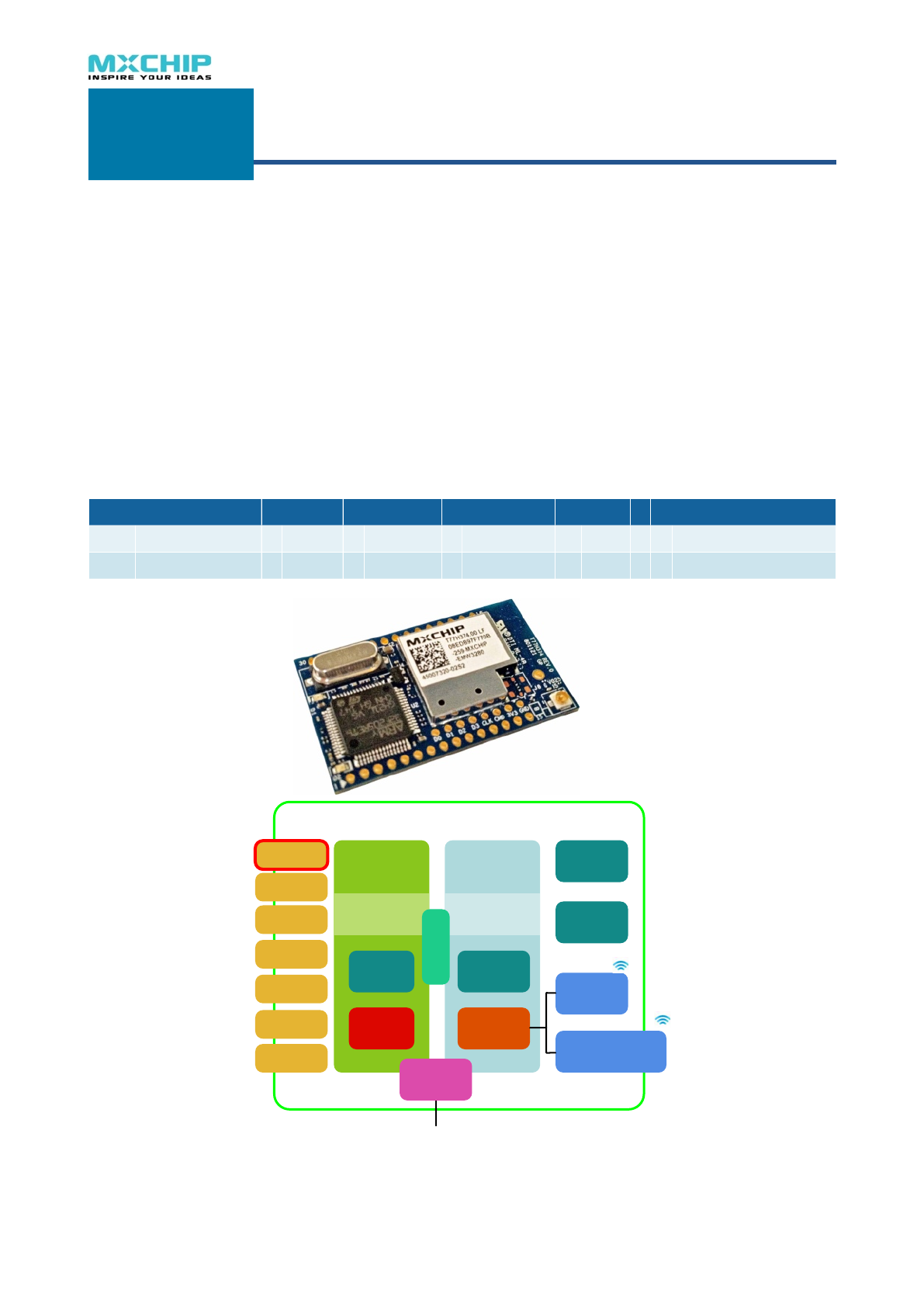
Overview
EMW3280 Wi-Fi modules developed by
MXCHIP integrate the TCP/IP protocol, IEEE
802.11b/g MAC and PHY. Wireless network
function can be deployed on user's products
easily. EMW3280 will save your development time
and greatly improve your product’s
competitiveness.
This product line is used to convert data
between UART and WLAN and support all of the
IEEE 802.11i security modes.
Applications
Building Automation / Access Control
Intelligent home appliances
Medical/Health Care
Industrial Automation Systems
Point Of Sale system (POS)
Auto electronics
Communicate with smart phones and
Products List
EMW
EMW
3
3
Generation
Generation
Function
Function
Interface
Interface
-
Package
Package
EMW
Embedded Wi-Fi
3
Module
2
3rd(2012)
8
Full function
0
UART
2
2.0mm lead pitch pins
4
2.0mm LGA
!
EMW Wi-Fi module hardware block
Network
Processor
120MHz CortexM
MCU
Flash
1Mbytes
SRAM
128KB
WLAN
Subsystem
128MHz Feroceon
CPU
802.11 a/b/g/n
MAC &
Baseband
2.4GHz
Transceiver
On-board PCB
antenna
U.F.L connector
8MHz OSC
1.8V regulator
PRODUCT BRIEF
GS1011
Ultra Low-Power Wireless Single Chip
PRODUCT OVERVIEW
GS1011 device is a highly integrated ultra low power wireless single chip which
contains an 802.11 radio, media access controller (MAC) and baseband processor,
on-chip flash memory and SRAM, and an applications processor all on a single
package. The GS1011 supports the full 802.11b (11Mbps) data rates providing
scalability on data throughput for higher bandwidth application while still providing
the ultra low power consumption for years of battery life. The GS1011 is pin and
package compatible with the GS1010 enabling seamless hardware upgrade fo
r
current designs. Along with its embedded software stack it offers a highly scalable,
reliable, manageable and secure wireless link to meet the growing demand o
f
wireless sensor networks utilizing the broadly accepted IEEE 802.11 standards
infrastructure. This solution is ideal for use in smart energy, building automation,
industrial and commercial automation and cold storage monitoring applications. In
addition, the solution provides capabilities such as location awareness which also
make it well suited for logistics and supply chain applications for tracking asset
location and status.
FEATURES & BENEFITS
Highly Integrated wireless SOC with 802.11 radio, MAC and Baseband,
Integrated PA, Application CPU, RTC, SRAM and FLASH
Reduces system cost of implementing separate devices and lowers design complexity
Ultra small form-factor reduces board space
Supports IEEE 802.11
Lowers customer’s total cost of ownership (TCO) in network implementation and
management
Seamlessly integrates with existing 802.11b/g infrastructure and utilizes the 802.11
security, manageability, easeof-use, and quality of service
Supports full 802.11b data rates (up to 11 Mbps) for higher bandwidth applications
802.11i/WPA2 Authentication, AES
Hardware encryption
Enterprise level security &reliability for
sensor networks
Power Management
Optimized for battery powered application
with very low power consumption for
multiple years of battery life
Location Awareness
Enables users to trace and monitor assets
Multiple I/O: SPI, UART, PWM, I2C,
ADC, GPIO
Provides flexibility in system design for
easier integration
Firmware, Device drivers, Reference
Application SW, APIs, and SDK
Reduces customer development time for
application software enabling faster time to
market
Seamless HW upgrade to current
designs
Pin and package compatible with GS1010,
makes it drop in replacement onto current
GS1010 designs
GS1011 BLOCK DIAGRAM
Standby Power Domain
Network
Processor
WLAN
Subsystem
UART
Antenna
External Power Amp Control
(Optional)
RF Switch
44MHz XTAL
DC-DC Control
2x External Wake Up
32kHz XTAL
2x SPI
2x UART
2x ADC
I
2
C
3x PWM
32x GPIO ARM7 CPU
Battery (3.6V – 1.2V)
SPI
ADC
I
2
C
PWM
GPIO
ARM7 CPU
2.4 GHz
Transceiver
802.11
MAC &
Baseband
Flash
256KB
SRAM
128KB
RTC
2x Alarm
XTL
OSC
1.8 V Regulator
NVRAM
512 Bytes
3.3V Input
UART
SPI/I2S
ADC
DAC
Timer/PWM
I2C
GPIO
SDIO
Power
Mangement
MXCHIP CORPORATION
Wireless M2M Division
EMW3280 Wi-Fi module

Features
Fast, ease of use embedded system interface
UART baudrate is up to 921600
Max. data transmission speed: 90kbytes/s (UART)
Support UART hardware flow control which ensure reliable data transmission
in high speed mode
Simplified hardware connections
Secure, stable Wi-Fi link
Support AP chient mode, soft AP mode and Ad-hoc mode
Secure, stable Wi-Fi link
Auto recover from Wi-Fi’s disconnection
Support WPA/WPA2 PSK, WEP encryption
IPEX antenna connector, on board PCB antenna
CE,FCC passed
Embedded TCP/IP stack
Support UDP protocol, broadcast and unicast
Support TCP protocol, act as TCP server or client
Allow 3 connections from TCP client under TCP server mode
Auto reconnect after TCP link is lost
Transfer data to internet through a gateway
Support DNS service
Flexible configuration and management
Use EMSP commands to control and config module through UART
Send EMSP commands from Wi-Fi network
Configuration on build-in html pages
Configuration software is provided on multiple platforms
Designed for embedded systems
Less than 220mA in running mode
Less than 1mA in standby mode
Less than 30mA in low power mode, network connection is maintained
Time interval from reset to Wi-Fi connection is less than 2 seconds
Reliable quality, comprehensive technical services
Industrial temperature range: -4080℃
Module test appliance is provided
ROSH certification passed
Evaluation boards, API library and test source codes are provided
EMW3280 Wi-Fi module

录
1. Function Description!1
1.1.Features!1
RF features!1
UART features !1
TCP/IP features !1
1.2.Electrical Parameters!2
1.2.1.Absolute maximum ratings: Voltage & Current!2
1.2.2.Operating conditions: Voltage & Current!2
1.2.3.Digital I/O port characteristics!3
Output voltage levels!3
Output voltage levels!3
NRST pin characteristics !3
1.2.4.Absolute maximum ratings: Temperature!3
1.2.5.Absolute maximum ratings: The Electromagnetic Environment Electrostatic discharge (ESD)!3
1.2.6.Static latch-up!4
1.2.7.RF characteristics !5
1.3.Mechanical Dimensions!9
1.3.1.Mechanical Dimensions Of EMW3280 (Metric units)!9
2. Module interface!10
2.1.Leds!10
2.2.Pinouts!10
2.3.Pin Arrangement!11
2.4.Typical Hardware Connection And Pin Description!11
3. Antenna!14
3.1.Minimizing radio interference!14
3.2.On-board Antenna Specification!14
3.3.U.F.L RF Connector!15
4. Lable!16
5. Recommended Reflow Profile!17
6. MSL/Storage Condition!17
7. Sales Information!18
EMW3280 Wi-Fi module


1. Function Description
EMW3280 Wi-Fi modules developed by MXCHIP integrate the TCP/IP protocol, IEEE
802.11b/g MAC and PHY. Wireless network function can be deployed on user's products easily.
EMW3280 will save your development time and greatly improve your product’s competitiveness.
EMW3280 modules can run in the industrial temperature rang: -40℃ to 85℃. The highest
baudrate of UART interface is 921600. It has two transfer modes: TCP, UDP, and support EMSP
commands to configure its parameters.
1.1. Features
★Single operation voltage: 3.3V.
★Power consumption: <220mA under run mode, current <1mA under standby mode.
★CPU frequency: 120MHz,flash size: 1M bytes,RAM size128k bytes.
★Two working modes: command mode and data transmission mode.
★Complete Wi-Fi wireless communications solutions, to reduce the resource requirements of
the application processor;
★Multipul configuration methods: build-in web pages,EMW tool box(PC software) and
EMSP commands;
RF features
★WLAN standard: IEEE 802.11b/g/n, Wi-Fi compatible.
★RF frequency: 2.4G ISM.
★Support AP chient mode, soft AP mode and Ad-hoc mode.
★WEP40 and WEP104 encryption (64/128bit), support open system or shared key.
★WPA/WPA2 PSK encryption, use AES or TKIP encryption algorithm.
★Auto recover from Wi-Fi disconnection.
★Time interval from reset to Wi-Fi connection is less than 2 seconds.
UART features
★UART Baudrate:1200-921600;
★Highest transmission speed: 90kbytes/s(send or receive), 60kbytes/s(send & receive both).
★upport UART hardware flow control that provide the reliable data transmission
TCP/IP features
★Support DNS service.
★Support DHCP client and DHCP server.
★Support network data transmission protocol: TCP, UDP;
★TCP server or client.
★Reliable TCP link management: Automatic reconnect when the connection was lost.
★As a TCP server, allow 3 TCP connection from the clients.
★UDP broadcast or unicast.
! ! EMW3280 Wi-Fi module
1
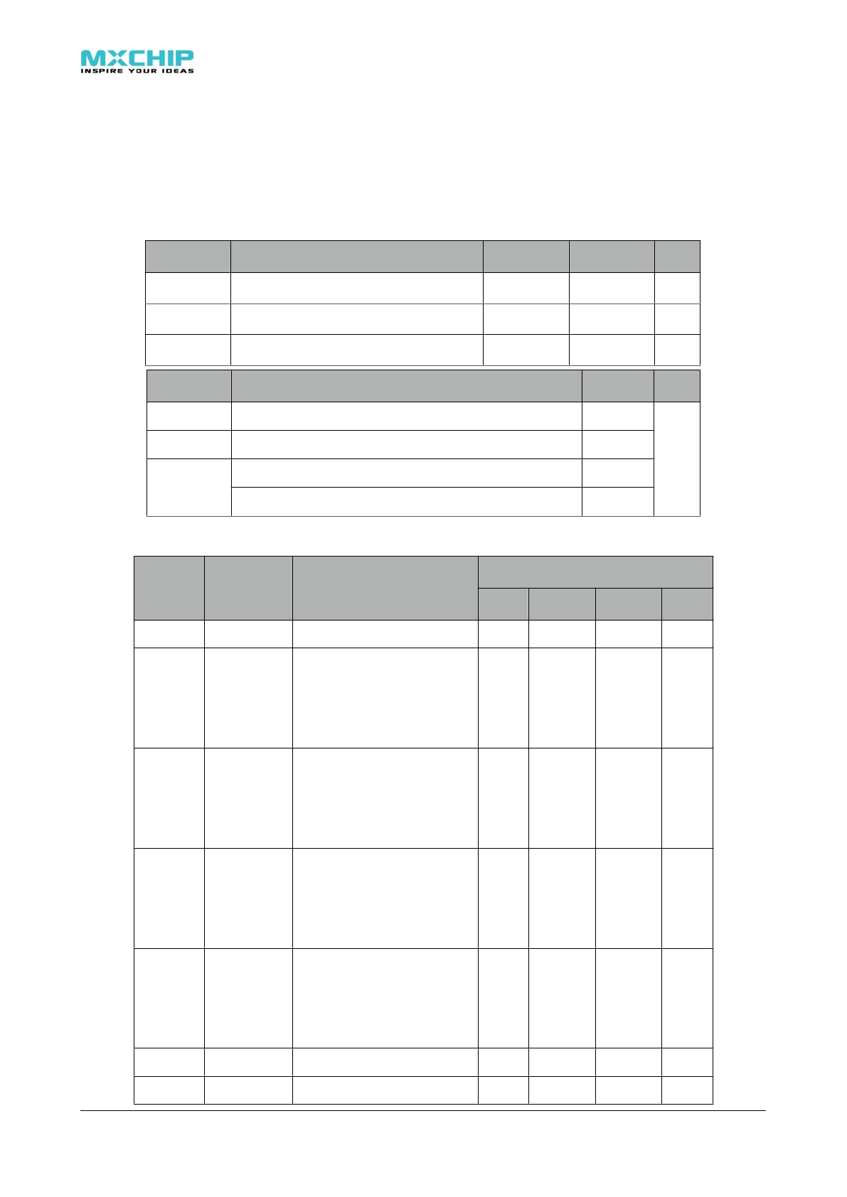
1.2. Electrical Parameters
1.2.1. Absolute maximum ratings: Voltage & Current
Stresses above the absolute maximum ratings may cause permanent damage to the device.
These are stress ratings only and functional operation of the device at these conditions is not
implied. Exposure to maximum rating conditions for extended periods may affect device
reliability.
Symbol
Ratings
Min
Max
Unit
VDD–VSS
Voltage
–0.3
4.0
V
VIN
Input voltage on five volt tolerant pin
VSS −0.3
5.5
V
VIN
Input voltage on any other pin
VSS −0.3
VDD+0.3
V
Symbol
Ratings
Max
Unit
IVDD
Total current into VDD power lines (source)
320
mA
IVSS
Total current out of VSS ground lines (sink)
320
mA
IIO
Output current sunk by any I/O and control pin
25
mA
IIO
Output current source by any I/Os and control pin
-25
mA
1.2.2. Operating conditions: Voltage & Current
Symbol
Note
Conditions
Specification
Specification
Specification
Specification
Symbol
Note
Conditions
Min.
Typical
Max.
Unit
DD
IVDD
Current
VDD=3.3V, normal
2437 MHz,18 dBm,
11 Mbps CCK
TX Speed:80kbytes/s
219
224
230
mA
IVDD
Current
VDD=3.3V, normal
2437 MHz,18 dBm,
11 Mbps CCK
TX Speed:10kbytes/s
199
202
204
mA
IVDD
Current
VDD=3.3V, normal
2437 MHz,15 dBm,
54 Mbps OFDM
TX Speed:80kbytes/s
203
204
205
mA
IVDD
Current
VDD=3.3V, normal
2437 MHz,15 dBm,
54 Mbps OFDM
TX Speed:10kbytes/s
199
200
202
mA
IVDD
Current
VDD=3.3V,Receive mode
182
185
188
mA
IVDD
Current
VDD=3.3V,Sleep mode
50
60
uA
! ! EMW3280 Wi-Fi module
2
VVoltage 3.0 3.3 3.5 V
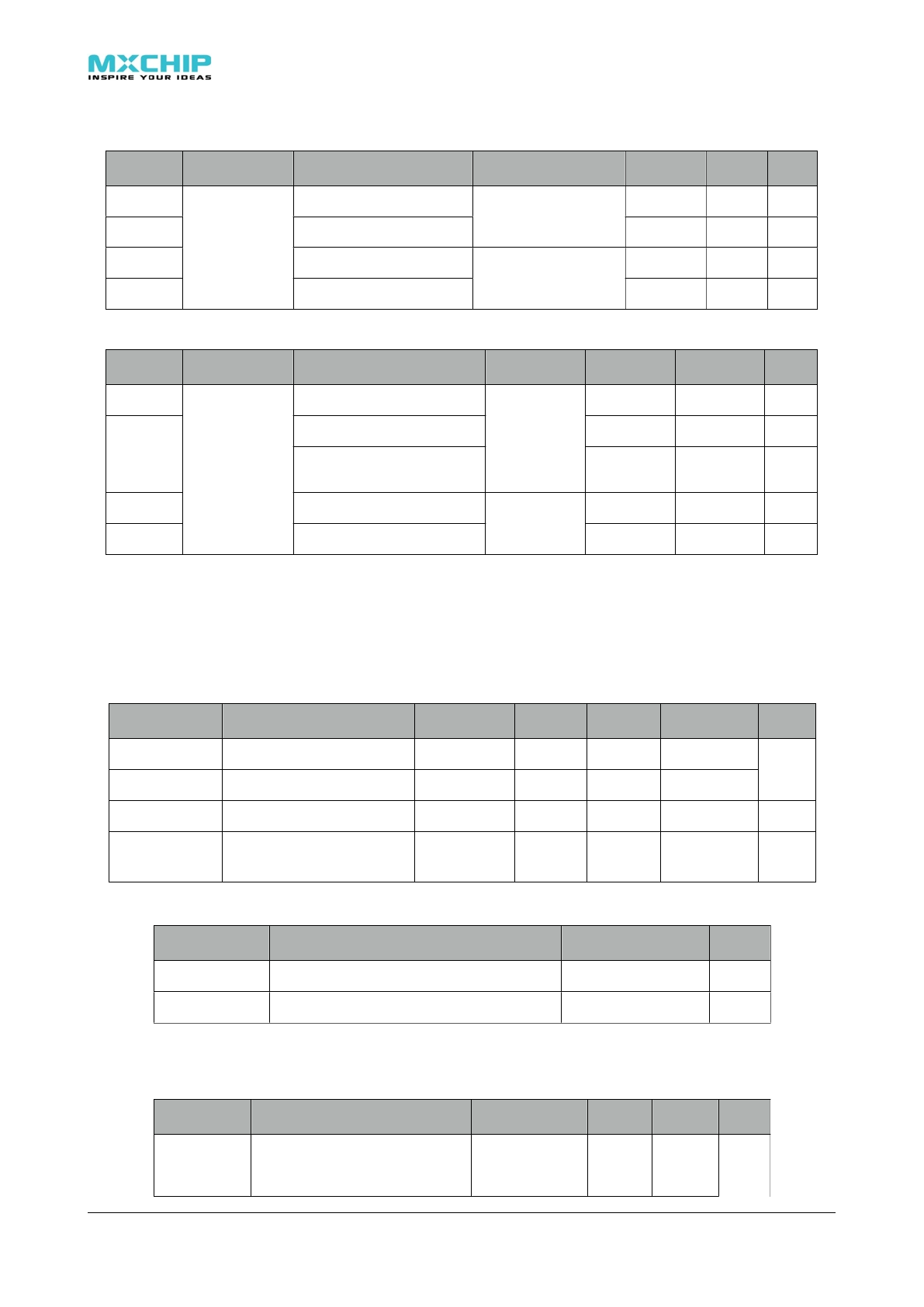
1.2.3. Digital I/O port characteristics
Output voltage levels
Symbol
Note
Parameter
Conditions
Min.
Max.
Unit
VOL
UART & IO
output voltage
Output low level voltage
IIO = +8 mA
2.7 V < VDD < 3.6 V
0.4
V
VOH
UART & IO
output voltage
Output high level voltage
IIO = +8 mA
2.7 V < VDD < 3.6 V
VDD-0.4
V
VOL
UART & IO
output voltage
Output low level voltage
IIO = +20 mA
2.7 V < VDD < 3.6 V
1.3
V
VOH
UART & IO
output voltage
Output high level voltage
IIO = +20 mA
2.7 V < VDD < 3.6 V
VDD-1.3
V
Output voltage levels
Symbol
Note
Parameter
Conditions
Min.
Max.
Unit
VIL
UART & IO
input voltage
Input low level voltage
TTL level
-0.5
0.8
V
VIH
UART & IO
input voltage
Input high level voltage
TTL level
2
VDD+0.5
V
VIH
UART & IO
input voltage
Input high level voltage
(5V input tolerant)
TTL level
2
5.5
V
VIL
UART & IO
input voltage
Input low level voltage
CMOS level
-0.5
0.35VDD
V
VIH
UART & IO
input voltage
Input high level voltage
CMOS level
0.65VDD
VDD+0.5
V
NRST pin characteristics
The NRST pin input driver uses CMOS technology. EMW3280 contains RC(resistance-
capacitance) reset circuit which ensures the module reset accurately when it powers up. If you
need to reset manually, just connect the external control signals to the reset pins directly.
Additional, you can also control the reset by means of the EMSP command.
Symbol
Item
Conditions
Min.
Typical
Max.
Unit
VIL(NRST)
/RESET input low level
–0.5
0.8
V
VIH(NRST)
/RESET input high level
2
VDD+0.5
V
RPU
Resistor for Pulling up
VIN = VSS
7.5
8
8.3
kΩ
CPD
Capacitor for charging and
Resetting
100
1000
pF
1.2.4. Absolute maximum ratings: Temperature
Symbol
Ratings
Max
Unit
TSTG
Storage temperature
–55 to +125
℃
TA
Working temperature
-40 to +85
℃
1.2.5. Absolute maximum ratings: The Electromagnetic Environment
Electrostatic discharge (ESD)
Symbol
Ratings
Conditions
Class
Max
Unit
VESD(HBM)
Electrostatic discharge voltage
(human body model)
TA = +25 °C
conforming to
JESD22-A114
2
2000
V
! ! EMW3280 Wi-Fi module
3

Symbol
Ratings
Conditions
Class
Max
Unit
VESD(CDM)
Electrostatic discharge voltage
(charge device model)
TA = +25 °C
conforming to
JESD22-C101
II
500
V
1.2.6. Static latch-up
These tests are compliant with EIA/JESD 78A IC latch-up standard.
Symbol
Parameter
Class
Class
LU
Static latch-up class
TA = +105 °C conforming to JESD78A
II level A
! ! EMW3280 Wi-Fi module
4
1.2.7. RF characteristics
Basic characteristics
Item Specification
Operating Frequency 2.412~2.472GHz
WiFi Standard 802.11b/g/n(1x1)*
Modulation Type
11b: DBPSK, DQPSK,CCK for DSSS
11g: BPSK, QPSK, 16QAM, 64QAM for OFDM
11n: MCS0~7,OFDM*
Data Rates
11b:1, 2, 5.5 and 11Mbps
11g:6, 9, 12, 18, 24, 36, 48 and 54 Mbps
11n: MCS0~7, up to 150Mbps
Antenna type One U.F.L connector for external antenna
PCB printed ANT (Reserve)
IEEE802.11b mode
Item Specification
Modulation Type DSSS / CCK
Frequency range 2400MHz~2483.5MHz
Channel CH1 to CH13
Data rate 1, 2, 5.5, 11Mbps
TX Characteristics Min. Typical Max. Unit
Transmitter Output Power
Transmitter Output Power
Transmitter Output Power
Transmitter Output Power
Transmitter Output Power
11b Target Power 16 18 dBm
Spectrum Mask @ target power
Spectrum Mask @ target power
Spectrum Mask @ target power
Spectrum Mask @ target power
Spectrum Mask @ target power
fc +/-11MHz to +/-22MHz -30 dBr
fc > +/-22MHz -50 dBr
Frequency Error -25 -1 +25 ppm
Constellation Error( peak EVM)@ target power
Constellation Error( peak EVM)@ target power
Constellation Error( peak EVM)@ target power
Constellation Error( peak EVM)@ target power
Constellation Error( peak EVM)@ target power
1~11Mbps 35%
RX Characteristics Min. Typical Max. Unit
Minimum Input Level Sensitivity
Minimum Input Level Sensitivity
Minimum Input Level Sensitivity
Minimum Input Level Sensitivity
Minimum Input Level Sensitivity
1Mbps (FER≦8%) -97 -83 dBm
2Mbps (FER≦8%) -93 -80 dBm
5.5Mbps (FER≦8%) -91 -79 dBm
11Mbps (FER≦8%) -89 -76 dBm
Maximum Input Level (FER≦8%) -10 dBm
! ! EMW3280 Wi-Fi module
5
25
<
IEEE802.11g mode
Item Specification
Modulation Type OFDM
Frequency range 2400MHz~2483.5MHz
Channel CH1 to CH13
Data rate 6, 9, 12, 18, 24, 36, 48, 54Mbps
TX Characteristics Min. Typical Max. Unit
Transmitter Output Power
Transmitter Output Power
Transmitter Output Power
Transmitter Output Power
Transmitter Output Power
11g Target Power 13 15 dBm
Spectrum Mask @ target power
Spectrum Mask @ target power
Spectrum Mask @ target power
Spectrum Mask @ target power
Spectrum Mask @ target power
fc +/-11MHz -20 dBr
fc +/-20MHz -28 dBr
fc > +/-30MHz -40 dBr
Frequency Error -25 -1.1 +25 ppm
Constellation Error( peak EVM)@ target power
Constellation Error( peak EVM)@ target power
Constellation Error( peak EVM)@ target power
Constellation Error( peak EVM)@ target power
Constellation Error( peak EVM)@ target power
6Mbps -5 dBm
9Mbps -8 dBm
12Mbps -10 dBm
18Mbps -13 dBm
24Mbps -16 dBm
36Mbps -19 dBm
48Mbps -22 dBm
54Mbps -30 -25 dBm
RX Characteristics Min. Typical Max. Unit
Minimum Input Level Sensitivity
Minimum Input Level Sensitivity
Minimum Input Level Sensitivity
Minimum Input Level Sensitivity
Minimum Input Level Sensitivity
6Mbps (FER≦10%) -90 -82 dBm
9Mbps (FER≦10%) -88 -87 dBm
12Mbps (FER≦10%) -86 -79 dBm
18Mbps (FER≦10%) -85 -77 dBm
24Mbps (FER≦10%) -82 -74 dBm
36Mbps (FER≦10%) -79 -70 dBm
48Mbps (FER≦10%) -75 -66 dBm
54Mbps (FER≦10%) -72 -65 dBm
Maximum Input Level (FER≦10%) -20 dBm
! ! EMW3280 Wi-Fi module
6
25
<
IEEE802.11n 20MHz bandwidth mode
Item Specification
Modulation Type MIMO-OFDM
Channel CH1 to CH13
Data rate MCS0/1/2/3/4/5/6/7
TX Characteristics Min. Typical Max. Unit
Transmitter Output Power
Transmitter Output Power
Transmitter Output Power
Transmitter Output Power
Transmitter Output Power
11n HT20 Target Power 13 15 dBm
Spectrum Mask @ target power
Spectrum Mask @ target power
Spectrum Mask @ target power
Spectrum Mask @ target power
Spectrum Mask @ target power
fc +/-11MHz -20 dBr
fc +/-20MHz -28 dBr
fc > +/-30MHz -45 dBr
Frequency Error -25 -1.2 +25 ppm
Constellation Error( peak EVM)@ target power
Constellation Error( peak EVM)@ target power
Constellation Error( peak EVM)@ target power
Constellation Error( peak EVM)@ target power
Constellation Error( peak EVM)@ target power
MCS0 -5 dBm
MCS1 -10 dBm
MCS2 -13 dBm
MCS3 -16 dBm
MCS4 -19 dBm
MCS5 -22 dBm
MCS6 -25 dBm
MCS7 -32 -28 dBm
RX Characteristics Min. Typical Max. Unit
Minimum Input Level Sensitivity
Minimum Input Level Sensitivity
Minimum Input Level Sensitivity
Minimum Input Level Sensitivity
Minimum Input Level Sensitivity
MCS0 (FER≦10%) -89 -82 dBm
MCS1 (FER≦10%) -86 -79 dBm
MCS2 (FER≦10%) -84 -77 dBm
MCS3 (FER≦10%) -82 -74 dBm
MCS4 (FER≦10%) -78 -70 dBm
MCS5 (FER≦10%) -74 -66 dBm
MCS6 (FER≦10%) -72 -65 dBm
MCS7 (FER≦10%) -69 -64 dBm
Maximum Input Level (FER≦10%) -20 dBm
! ! EMW3280 Wi-Fi module
7
<25
IEEE802.11n 40MHz bandwidth mode
Item Specification
Modulation Type MIMO-OFDM
Channel CH3 to CH11
Data rate MCS0/1/2/3/4/5/6/7
TX Characteristics Min. Typical Max. Unit
Transmitter Output Power
Transmitter Output Power
Transmitter Output Power
Transmitter Output Power
Transmitter Output Power
11n HT20 Target Power 12 14 dBm
Spectrum Mask @ target power
Spectrum Mask @ target power
Spectrum Mask @ target power
Spectrum Mask @ target power
Spectrum Mask @ target power
fc +/-22MHz -20 dBr
fc +/-40MHz -28 dBr
fc > +/-60MHz -45 dBr
Frequency Error -25 -1.3 +25 ppm
Constellation Error( peak EVM)@ target power
Constellation Error( peak EVM)@ target power
Constellation Error( peak EVM)@ target power
Constellation Error( peak EVM)@ target power
Constellation Error( peak EVM)@ target power
MCS0 -5 dBm
MCS1 -10 dBm
MCS2 -13 dBm
MCS3 -16 dBm
MCS4 -19 dBm
MCS5 -22 dBm
MCS6 -25 dBm
MCS7 -31 -28 dBm
RX Characteristics Min. Typical Max. Unit
Minimum Input Level Sensitivity
Minimum Input Level Sensitivity
Minimum Input Level Sensitivity
Minimum Input Level Sensitivity
Minimum Input Level Sensitivity
MCS0 (FER≦10%) -87 -79 dBm
MCS1 (FER≦10%) -84 -76 dBm
MCS2 (FER≦10%) -81 -74 dBm
MCS3 (FER≦10%) -79 -71 dBm
MCS4 (FER≦10%) -75 -67 dBm
MCS5 (FER≦10%) -71 -63 dBm
MCS6 (FER≦10%) -69 -62 dBm
MCS7 (FER≦10%) -66 -61 dBm
Maximum Input Level (FER≦10%) -20 dBm
! ! EMW3280 Wi-Fi module
8
25
<
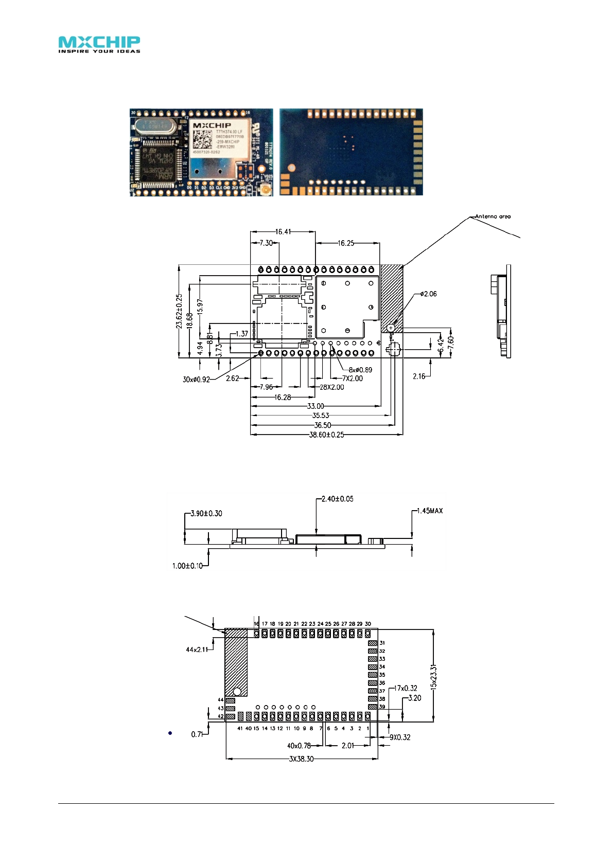
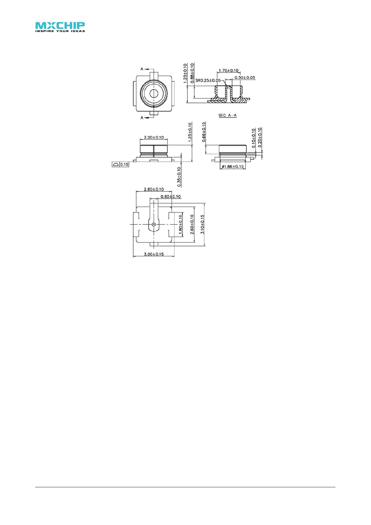
1.3. Mechanical Dimensions
1.3.1. Mechanical Dimensions Of EMW3280 (Metric units)
!
!
Figure 1.1 EMW3280 top view
Figure 1.2 EMW3280 side view
Figure 1.3 EMW3280 bottom view
! ! EMW3280 Wi-Fi module
9
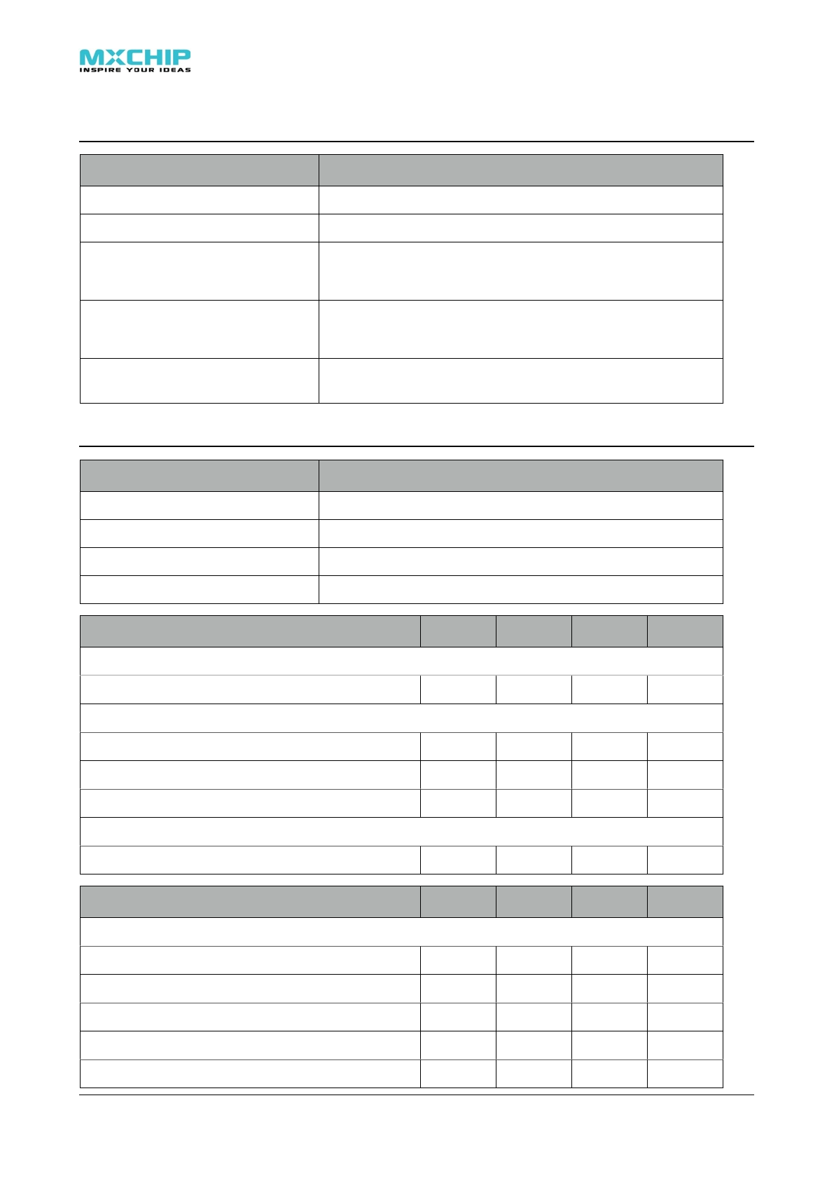
2. Module interface
2.1. Leds
D1
D2
Table 2.1 LED functions
Name
Color
Description
D1
Green
On: Initialize successful, working in normal
Off:Initialize failed, or standby mode
Flashing (Short/short/short): Firmware update mode
Flashing (Short/long/short): Illegal firmware version
D2
Red
Flashing: Data transmission (test failed in MFG mode)
On:Wi-Fi is connected
Off:Wi-Fi disconnected
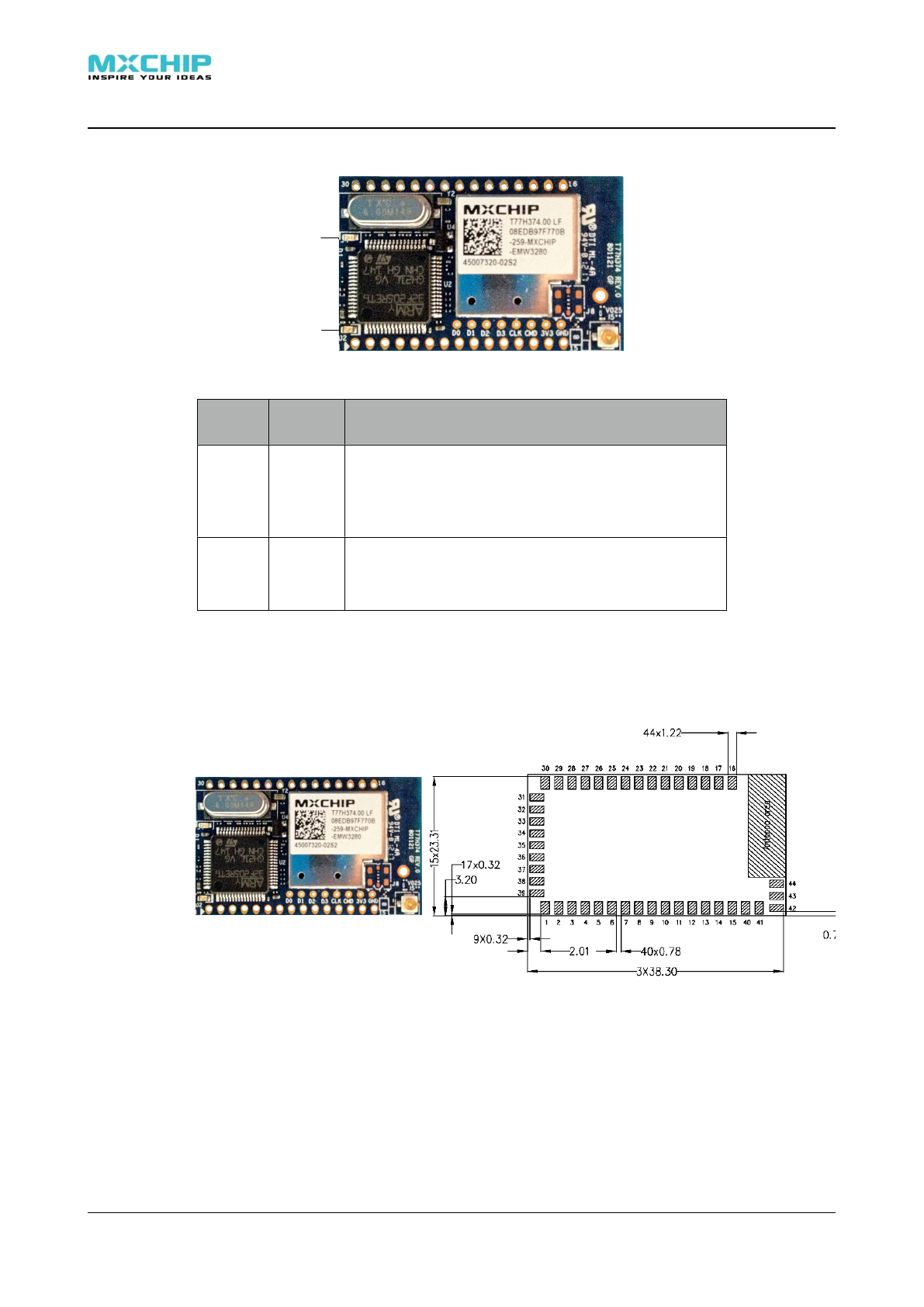
2.2. Pinouts
EMW3280has two groups of pins (1X15 +1X15). The lead pitch is 2mm.
EMW3280’s pinout is shown in the Figure 2.1. Table 2.2 lists the pin functions.
Figure2.1 EMW3280: appearance and pinout
! ! EMW3280 Wi-Fi module
10
2.3. Pin Arrangement
Figure 2.2 EMW3280 pin arrangement
Pins
Pin Name
FT
Pins
Pin Name
FT
1-14
NC
22
UART_TXD(OUT)
15
GND
23
UART_RXD(IN)
√
16
nWI-FI LED(OUT)
BOOT(IN)
24
VDD
17
nRESET(IN)
25
GND
18
IO1
26-28
NC
19
NC
29
nWAKE_UP(IN)
20
nUART_RTS(OUT)
30
STATUS(IN)
√
21
nUART_CTS(IN)
√
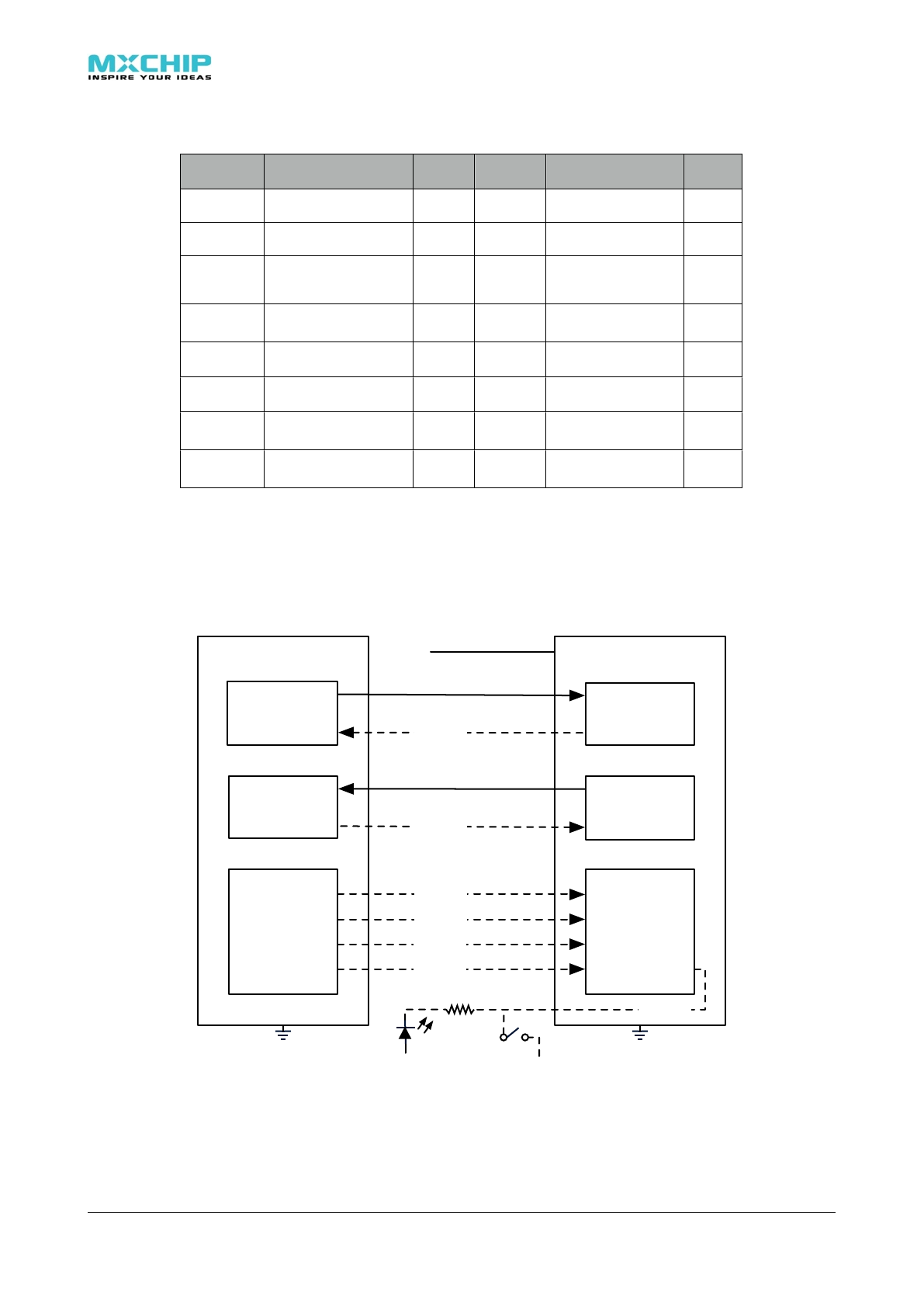
2.4. Typical Hardware Connection And Pin Description
EMW3280 consume more power in data transmission. It is recommended that the VDD
power supply is connected in parallel with a 330uF/5V solid capacitor, or a high-frequency
electrolytic capacitor (low ESR), this can reduce the requirements of DC power supply, A 300mA
LDO can be used (500mA LDO is recommended).
Host Device
UART TX
UART RX
IO circult
WI-Fi Module
UART TX
IO circult
UART RX
TX
nCTS
UART_RXD
nUART_RTS
RX
nRTS
UART_TXD
nUART_CTS
IO2
IO1
IO3
STATUS
nRESET
WAKEUP
Optional
Optional
Optional
Optional
Optional
3.3V
Optional
nWIFI LED/BOOT
3.3V VDD
GND
1K
IO4 FC(IO1)
Optional
Figure 2.3 Typical hardware connection: TTL/CMOS UART Interface
! ! EMW3280 Wi-Fi module
11
Host Device
RS232 TX
RS232 RX
IO circult
WI-Fi Module
TX circult
IO circult
RX circult
TX
nCTS
UART_RXD
nUART_RTS
RX
nRTS
UART_TXD
nUART_CTS
IO2
IO1
IO3
STATUS
nRESET
WAKEUP
Optional
Optional
Optional
Optional
Optional
3.3V
Optional
nWIFI LED/BOOT
GND
1K
MAX3232
C1+
C1-
C2+
C2-
Vcc
V+
V-
1
3
4
5
3.3V
16
2
6
14 T1OUT T1IN 11
R1IN R1OUT
13 12
T2OUT T2IN
R2IN R2OUT
710
89
IO3 FC(IO1)
Optional
3.3V VDD
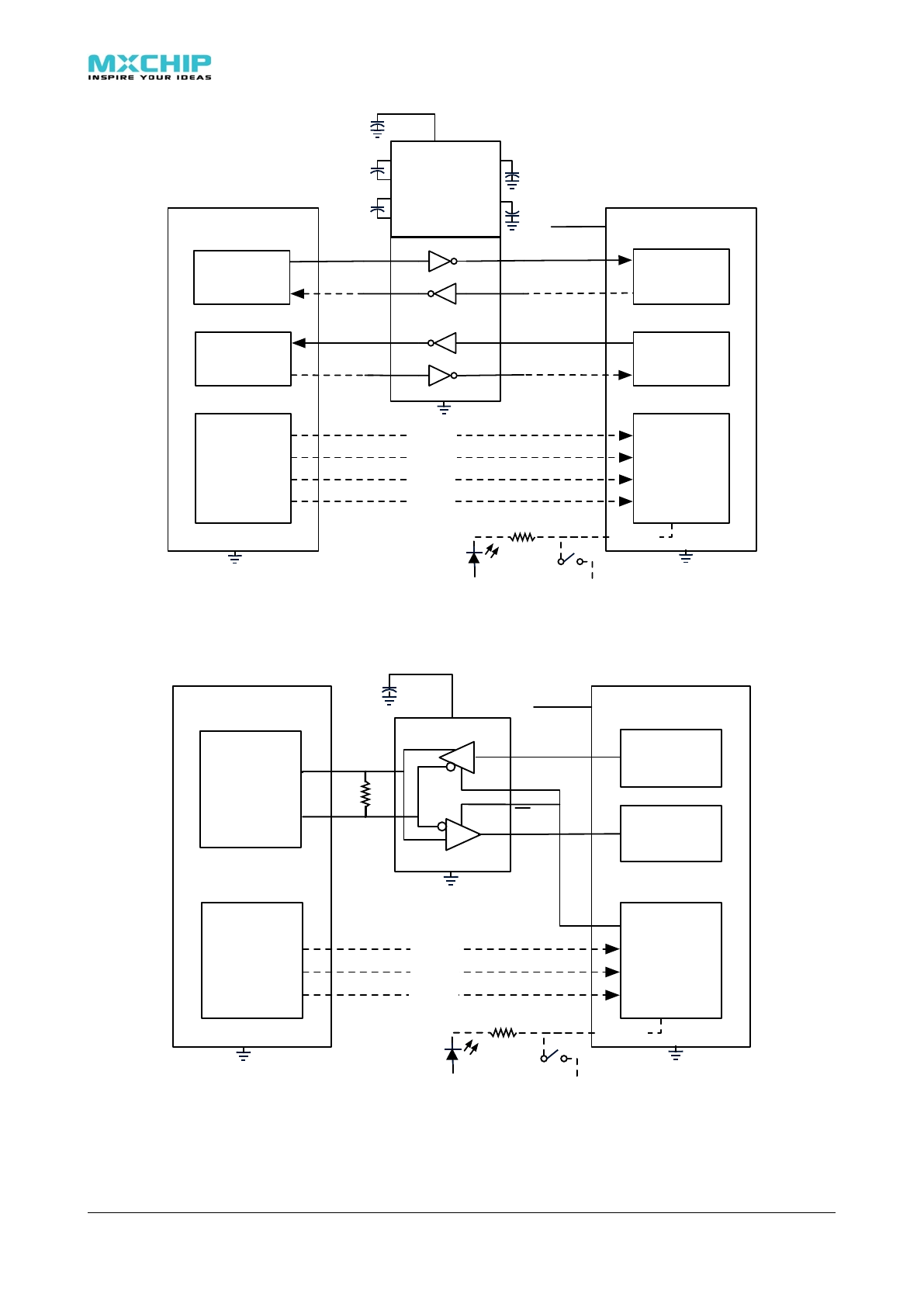
Figure 2.4 Typical hardware connection: RS232 UART Interface
MAX3485
3.3V
VCC
DI
RO
A
B
DE
RE
Host Device
RS485
IO circult
WI-Fi Module
RX circult
IO circult
TX circult
IO2
IO1
IO3
STATUS
nRESET
WAKEUP
Optional
Optional
Optional
3.3V
Optional
nWIFI LED/BOOT
GND
1K
HDC(IO1)
3.3V VDD
Figure 2.5 Typical hardware connection: RS485 UART Interface
! ! EMW3280 Wi-Fi module
12

Table 2.3 Pin functions
Pin
Type
Function
VDD
Power input.
GND
Grounding.
UART_RXD
I, FT
UART Data input.
UART_TXD
O
UART Data output.
nUART_CTS
I, FT
UART allow to send, active low.
nUART_RTS
O
UART is ready to receive, active low.
STATUS(IN)
I, FT,
PU
Set the operation mode, cooperation with BOOT pin:
WAKE_UP(IN)
I, PU
•Pull down: Enter standby mode
•Pull up: Wake up from standby mode
nRESET(IN)
I, PU
Pull down this pin for 1μs to reboot.
nWI-FI LED(OUT)
BOOT(IN)
O/I, PU
This pin has two functions:
nWIFI_LED:Output led D1 status, Low: D1 = on, High: D1 = off.
BOOT:Enter different operation modes when powered on or reset.
IO1
NC
IO1 can be configured by software
IO1
I
Set to Frame Control mode (FC), used in DTU mode:
Input low, EMW3280 store the received UART data in RAM.
Input high, EMW3280 send the buffed UART data over Wi-Fi network.
Refer document: RM0001_EMW3280 for details
IO1
O
Set to Half-duplex Control mode (HDC), used in DTU mode:
Output low, while receiving UART data
Output high, while sending UART data
NC
Undefined IOs. Leave them floating or grounding.
1. FT: = 5V input tolerant.
2. PU: The pin is at high level if no external signal is asserted.
3. PD: The pin is at low level if no external signal is asserted.
4. UART signals include: UART_TXD,UART_RXD,nUART_RTS和nUART_CTS.
5. Only VDD, GND UART_TXD and UART_RXD are needed in a simple connection.
6. We strong recommend that using STATUS signal to switch EMW3X80’s operation mode.
7. nRESET should not be forced pulled up by external circuit, otherwise standby mode and
internal watchdog would be unable to work properly. If an external signal is connected to
nRESET, this signal must be Open Drain Mode (OD).
8. Use BOOT pin and STATUS pin to define different working mode.
BOOT
STATUS
EMW3280 operation mode
0
0
MFG mode
0
1 (Default)
FW UPDATE mode
1 (Default)
0
Command mode (working mode)
1 (Default)
1 (Default)
DTU mode (working mode)
! ! EMW3280 Wi-Fi module
13
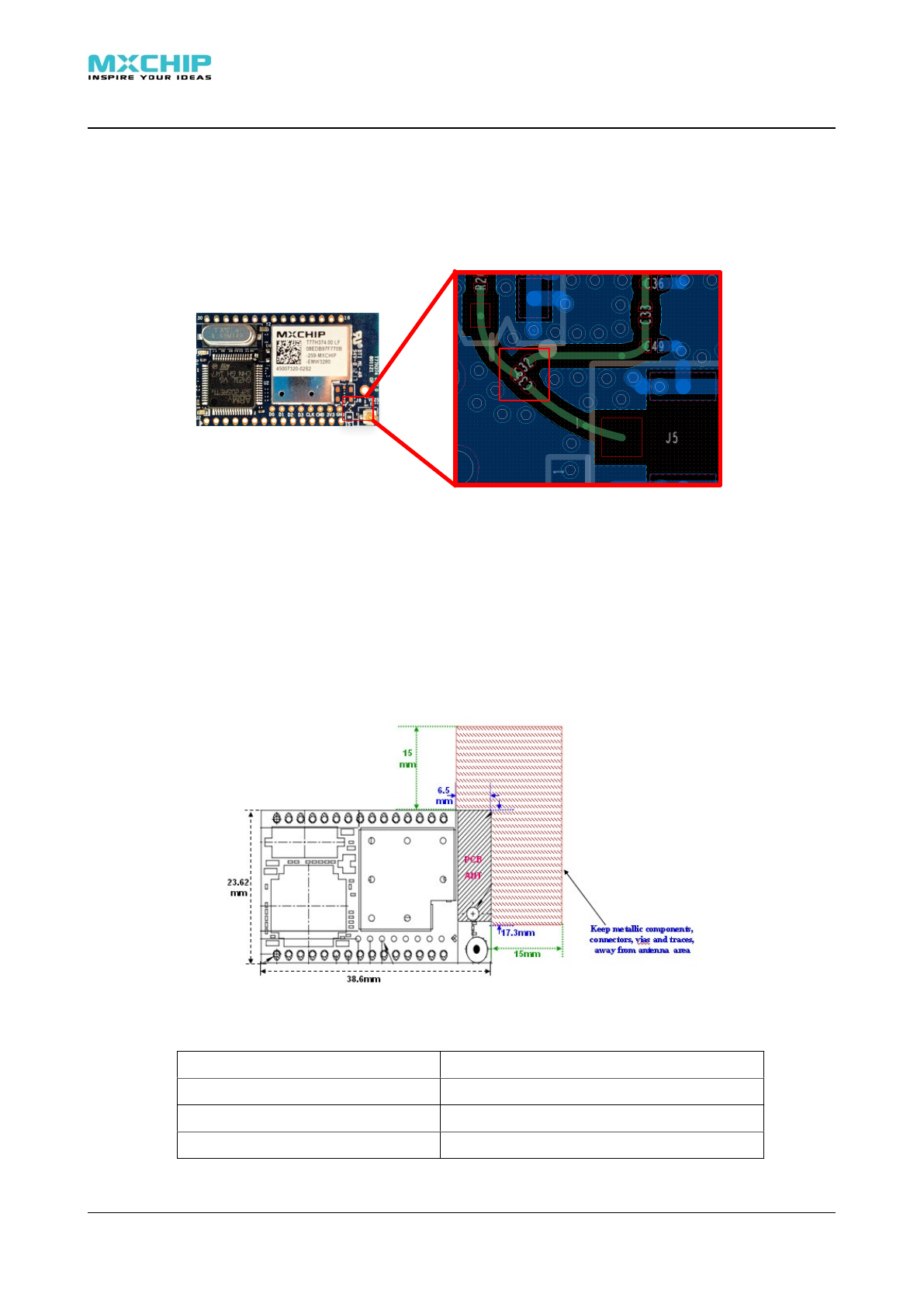
3. Antenna
There is co-layout design (C35&C32) for antenna connection. Normally, load the capacitor
c35(10pF/0201) , it means can use U.F.L RF connector for external antenna. If want to use on-
board PCB printed antenna, just need load the capacitor from C35 to C32.
In order to get the maximum performance, strongly suggest customer use external antenna
connected with U.F.L RF connector.
3.1. Minimizing radio interference
When integrating the WiFi module with on board PCB printed antenna, make sure
the area around the antenna end the module protrudes at least 15mm from the mother
board PCB and any metal enclosure. If this is not possible use the on board U.FL connector to
route to an external antenna.
The area (6.5mmx17.3mm) under the antenna end of the module should be keep clear of
metallic components, connectors, vias, traces and other materials that can interfere with the
radio signal.
3.2. On-board Antenna Specification
Operating Frequency
2.412~2.472GHz
VSWR (max)
<=2.5:1
Peak Gain
~2.1dBi
Antenna Type
PCB printed PiFA antenna
! ! EMW3280 Wi-Fi module
14
3.3. U.F.L RF Connector
This module use U.F.L type RF connector for external antenna connection.
! ! EMW3280 Wi-Fi module
15
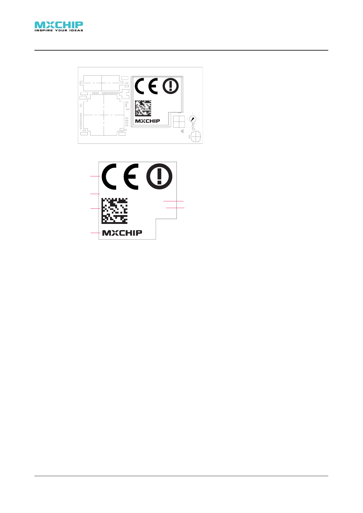
4. Lable
Label’s position is as follow:
FCC ID:XXXXXXXXXXXXXXXXX
XXXXXXXXXXXX
-EMW3280
-XXX
MO-VVSS
FCC ID:XXXXXXXXXXXXXXXXX
XXXXXXXXXXXX
-EMW3280
-XXX
MO-VVSS
A
B
C
D
E
F
A:CE logo
B:FCC ID
C:Two-dimensional code,XXXXXXXXXXXX-EMW3280-XXX,same mean as part E
D:Internal production mark
E:XXXXXXXXXXXX 12 digitals, EMW3280 MAC address
%EMW3280: Model
%XXX : Production date
F:MXCHIP logo
! ! EMW3280 Wi-Fi module
16

5. Recommended Reflow Profile
Reflow times<= 2times (Max.)
6. MSL/Storage Condition
! ! EMW3280 Wi-Fi module
17

7. Sales Information
To buy this product, please call MXCHIP \during the working hours. (Monday~Friday A.M.
9:00~12:00; P.M. 1:00~6:00)
Telephone: +86-21-52655026 / 52655025
Address: Floor 2, Building No.9, Lane 271, Qianyang Street, Putuo District, Shanghai
Post Code: 200333
Email:
sales@mxchip.com
8. Technical Support
To get technical support or other information, please visit
http://www.mxchip.com
To get telephone technical support, please call us during the working hours:
MCUs
+86 (021)52655026-822 Email:support@mxchip.com
Embedded wireless devices
+86 (021)58655026-812 Email:support@mxchip.com
Development tools
+86 (021) 52655026-822 Emali:support@mxchip.com
! ! EMW3280 Wi-Fi module
18
This device complies with Part 15 of the FCC Rules. Operation is subject
to the following two conditions: (1) this device may not cause harmful
interference, and (2) this device must accept any interference received,
including interference that may cause undesired operation.
Changes or modifications not expressly approved by the party
responsible for compliance could void the user's authority to operate the
equipment.
This equipment has been tested and found to comply with the limits for
a Class B digital device, pursuant to part 15 of the FCC Rules. These
limits are designed to provide reasonable protection against harmful
interference in a residential installation. This equipment generates
uses and can radiate radio frequency energy and, if not installed and
used in accordance with the instructions, may cause harmful interference
to radio communications. However, there is no guarantee that interference
will not occur in a particular installation. If this equipment does cause
harmful interference to radio or television reception, which can be
determined by turning the equipment off and on, the user is encouraged
to try to correct the interference by one or more of the following
measures:
-Reorient or relocate the receiving antenna.
-Increase the separation between the equipment and receiver.
-Connect the equipment into an outlet on a circuit different from that
to which the receiver is connected.
-Consult the dealer or an experienced radio/TV technician for help.
To satisfy FCC RF exposure requirements, a separation distance of 20 cm or more
should be maintained between the antenna of this device and persons during device
operation.
To ensure compliance, operations at closer than this distance is not recommended.
Limited by local law regulations, version for North America does not have region selection option.
Information for the OEM Integrators
This device is intended for OEM integrators only. Please see the full grant of
equipment document for restrictions.
Label Information to the End User by the OEM or Integrators
If the FCC ID of this module is not visible when it is installed inside another device,
then the outside of the device into which the module is installed must be label with
"Contains FCC ID: P53-EMW3280".