MYLAPS ACTIVE Beacon for laptiming User Manual part 2
MYLAPS BV Beacon for laptiming part 2
UserManual.wiki
>
MYLAPS
>
ACTIVE User Manual
>
User manual part 2
Contents
1.
User manual part 1
2.
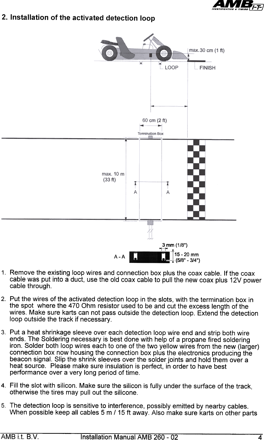
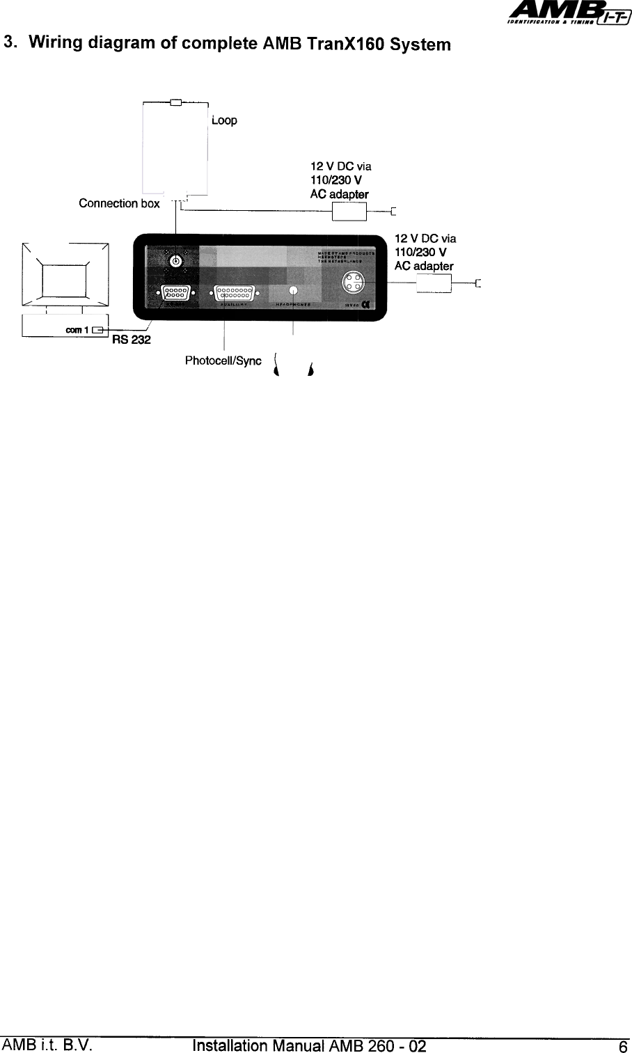
User manual part 2
User manual part 2
Navigation menu
Upload a User Manual
Namespaces
Wiki Guide
HTML
PDF
Info
Views
User Manual
Discussion / Help
Navigation