MYLAPS ACTIVE Beacon for laptiming User Manual part 2
MYLAPS BV Beacon for laptiming part 2
MYLAPS >
Contents
- 1. User manual part 1
- 2. User manual part 2
User manual part 2
6. EC and FCC regulations
Most electronic equipment produces some undesired interference at a close distance. To make sure the increasing
numbers of electronic equipment will not cause harmful interference, the CE (Europe) and FCC (US) regulations state
very low levels of interference that should not be exceeded. The AMB equipment does not exceed these levels.
The CE regulations also state the levels of interference generated by other sources which the equipment must be able to
tolerate without malfunctioning. These levels are considerably higher than the interference levels produced by the
electronic equipment itself. Cellular telephones however may generate interference levels which may cause other
electronic equipment to malfunction. AMB made sure its equipment is insensitive to the interference generated by cellular
telephones or other modern fonms of personal radio communications.
The FCC regulations for Infonmation Technology equipment which must be printed in the manuals state that you must
tolerate interference produced by others and you must switch-off when interference produced by your equipment is
experienced by others. The level of interference is strongly reduced when you increase the distance between two pieces
of electronic equipment. For example: your portable radio will most probably experience interference when placed on top
of your monitor, but will work very well a few feet away. Since the AMB transponders operate on magnetic induction they
have no antenna, but a built-in coil instead. The transponders do not produce an electromagnetic (radio) wave but only a
magnetic wave. The difference between an electromagnetic (radio) wave and a magnetic wave is that the
electromagnetic wave travels by itself over great distances and the magnetic wave does not. As the distance increases
the strength of the magnetic wave is greatly reduced. This is why AMB transponders are no transmitters.
This equipment complies with part 15 of the FCC rules. Operation is subject to the following two conditions: (1) This
equipment may not cause harmful interference, and (2) this equipment must accept any interference received, including
interference that may cause undesired operation.
Note: This equipment has been tested and found to comply with the limits for a Class B digital device, pursuant to part 15
of the FCC rules. These limits are designed to provide reasonable protection against harmful interference in a residential
installation. This equipment generates, uses and can radiate radio frequency energy and, if not installed and used in
accordance with the instructions, may cause harmful interference to radio communications. However, there is no
guarantee that interference will not occur in a particular installation. If this equipment does cause hanmful interference to
radio or television reception, which can be determined by turning the equipment off and on, the user is encouraged to try
to correct the interference by one or more of the following measures:
.Reorient or relocate the receiving antenna.
.Increase the separation between the equipment and receiver-
.Connect the equipment into an outlet on a circuit different from that to which the receiver is connected
EC Declaration of Conformity
The EC Declaration of Conformity is the method by which AMB i.t. declares that the AMB TranX260 system complies
with the EMC directive (89/336/EEC) and low voltage directive (73/23/EEC).
The AMB active loop consists of:
.AMB TranX active loop
Mains adapter 230 V AC/12 V DC
Applicable harmonised EMC standards
EN 55022
EN 50082-1
Class B, Information Technology Equipment
IEC 801-2 Electrostatic Discharge
IEC 801-3 Immunity to Radiated Electromagnetic Fields
IEC 801-4 Electrical Fast Transient, Burst
Low voltage directive
EN 60335
Authorised signature
Manufacturer
AMB i.t. B.V.
Herenweg 29A
2105 MB Heemstede
The Netherlands
Tel: ++31 235291893
Fax: ++31 235290156
Homepage : www.amb.nl
E-mail : support@amb.nl
H.Q. van Dooren
General Manager
AMB i.t. B.V. Installation Manual AMB 260- 02 9

,~§E!!:7
The AMB TranX 160 activated loop upgrade is specially designed to let an
existing AMB TranX 120/160 detection loop function normally, but function as
well as a beacon for the AMB DisplaylT.
The AMB DisplaylT, which is usually fitted to the steering wheel of a kart, detects
the signal produced by the activated detection loop while passing the loop and
indicates the actual lap time on its display.
Contents
1. COMPONENTS OF THE SYSTEM ..3
2. INSTALLATION OF THE ACTIVATED DETECTION LOOP 4
3. WIRING DIAGRAM OF COMPLETE AMB TRANX160 SYSTEM 6
4. OPERATING THE SYSTEM / TROUBLE SHOOTING 7
5. TECHNICAL SPECIFICATIONS 8
6. EC AND FCC REGULATIONS "..",,9
CE
AMB i.t. B.V. Manual number: AMB xxx/xx
All rights reserved .
This publication is to be used for the standard model of the product of the type given on the cover page.
Therefore the manufacturer cannot be held responsible for any damage resulting from the application of this
publication to the version actually delivered to you.
This publication has been written with great care. However, the manufacturer cannot be held responsible,
either for any errors occurring in this publication or for their consequences.
AMB i.t. B.V. Installation Manual AMB 260- 02 2
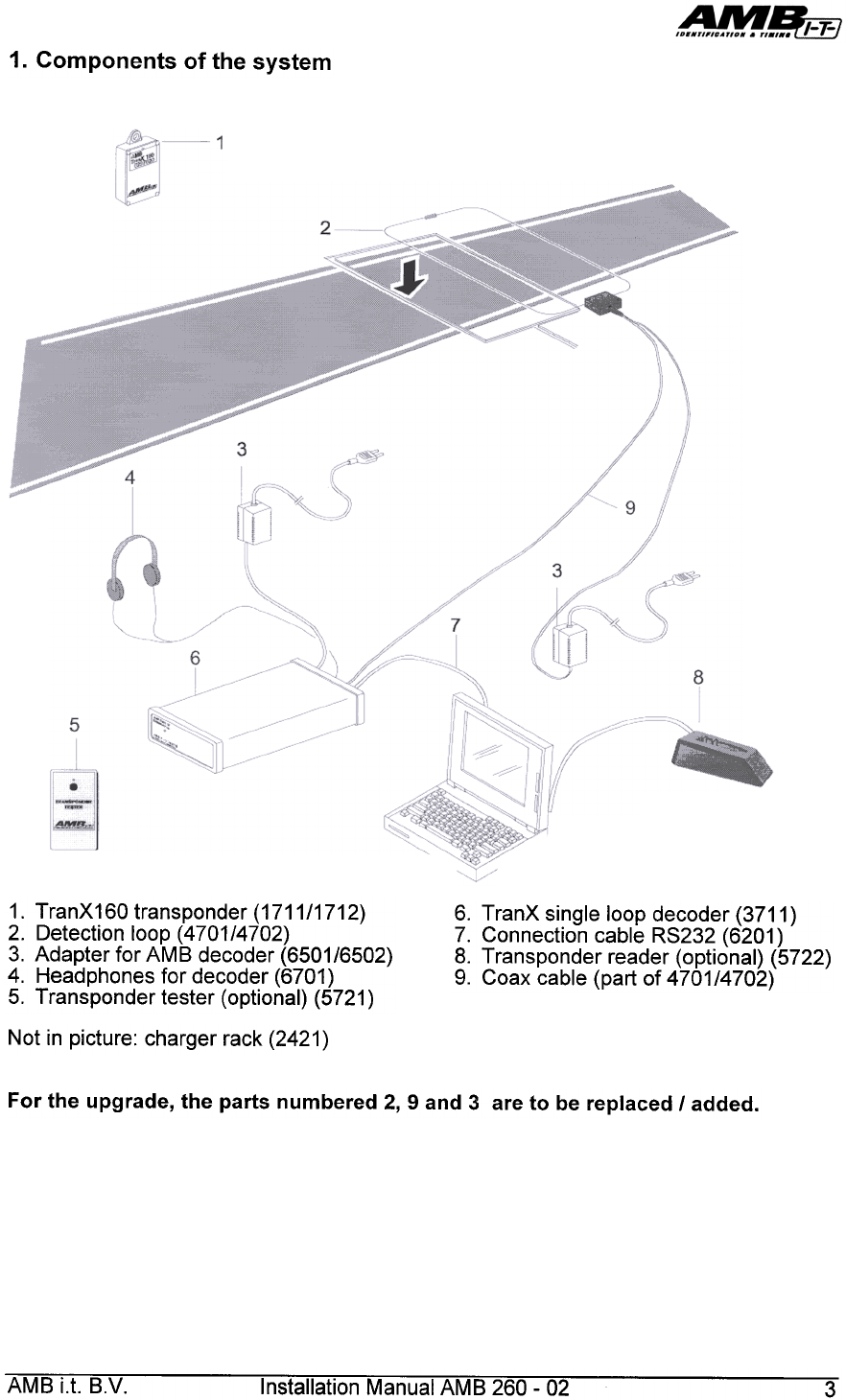
1. Components of the system
1. TranX160 transponder (1711/1712)
2. Detection loop (4701/4702)
3. Adapter for AMB decoder (6501/6502)
4. Headphones for decoder (6701)
5. Transponder tester (optional) (5721 )
6. TranX single loop decoder (3711 )
7. Connection cable RS232 (6201 )
8. Transponder reader (optional) (5722)
9. Coax cable (part of 4701/4702)
Not in picture: charger rack (2421 )
For the upgrade, the parts numbered 2, 9 and 3 are to be replaced I added.
AMB i.t. B.V. Installation Manual AMB 260- 02 3
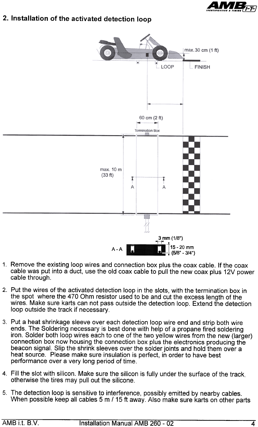
2. Installation of the activated detection loop
3 mm (1/8")
'"H'"
-20 mm
-3/4")
A-A
1. Remove the existing loop wires and connection box plus the coax cable. If the coax
cable was put into a duct, use the old coax cable to pull the new coax plus 12V power
cable through.
2. Put the wires of the activated detection loop in the slots, with the termination box in
the spot where the 470 Ohm resistor used to be and cut the excess length of the
wires. Make sure karts can not pass outside the detection loop. Extend the detection
loop outside the track if necessary.
3. Put a heat shrinkage sleeve over each detection loop wire end and strip both wire
ends. The Soldering necessary is best done with help of a propane fired soldering
iron. Solder both loop wires each to one of the two yellow wires from the new (larger)
connection box now housing the connection box plus the electronics producing the
beacon signal. Slip the shrink sleeves over the solder joints and hold them over a
heat source. Please make sure insulation is perfect, in order to have best
performance over a very long period of time.
4. Fill the slot with silicon. Make sure the silicon is fully under the surface of the track,
otherwise the tires may pullout the silicone.
5. The detection loop is sensitive to interference, possibly emitted by nearby cables.
When possible keep all cables 5 m 115 ft away. Also make sure karts on other parts
AMB i.t. B.V. Installation Manual AMB 260- 02 4
6. The 12V power cable may be installed alongside the coax cable leading to the AMB
TranX160 decoder. The 12V adapter powering the TranX activated detection loop
may be installed permanently, but must be well protected from water and humidity.
7. The activated detection loop may be powered permanently, even when the AMB
TranX decoder etc. are not installed or present. In this way producing the beacon
signal continuously for any DisplaylT that may be present on the track. Power
consumption is around 10 watts in total, depending on loop size.
8. All wiring of the loop must be installed according to the drawing in order to avoid a
serious degradation in performance. When joints in the loop are not soldered, the
beacon signal may, over time, when the joints become oxidised, interfere strongly
with the signals coming from passing transponders.
AMB i.t. B.V. Installation Manual AMB 260- 02 5
of the track will not get closer than 5 m /15 ft to the detection loop, to avoid false
inputs.
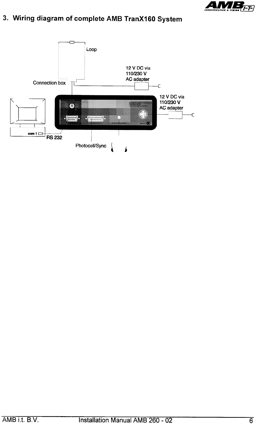
3. Wiring diagram of complete AMB TranX160 System
~
I LOOp
Connection box
I 12 V DC via
I 110/230 V
I
r---' AC adapter
" [::J-;:
d
12VDCvia
110/230 V
AC adapter
0-.:
~~
Photocell/Sync ~ j
AMB i.t. B.V. Installation Manual AMB 260- 02 6
4. Operating the system I Trouble shooting
Install the existing AMB TranX 160 system as usual and according to the instructions in
the manual. When the (new) coax cable is connected to the decoder, the TranX 160
system should operate as before.
Now plug in the 12V adapter powering the activated detection loop. The background
noise level may rise about 10 points, due to the (very low) noise level of the beacon now
operating.
When a connected sensor of an AMB DisplaylT is passed over the loop (not higher than
30 cm 11 foot) the DisplaylT should indicate.
The AMB TranX 160 system and the Activated loop (beacon) work fully independent of
each other and do not interact.
Beacon signal not present
Check if the AMB mains adapter powering the activated loop is connected to the mains
and that mains voltage is present. Make sure the 12V wiring to the activated loop is not
broken or short circuited. A properly operating activator consumes between 0.3 and 0.6
Amps depending of loop size.
When a loop wire is broken, the AMB TranX 160 system usually still operates, although
with reduced received signal strength and hits, but the activating signal (beacon) is no
longer present.
High background noise level
If, after installation of the activated loop, the background noise level has increased
strongly, disconnect the 12V adapter from the mains, in order to see if noise enters the
detection loop from the mains. Please make also sure the 12V cable leading to the
activated loop does not run alongside power and/or data cables, which may also be a
source of interference.
Other uses of the activated loop
The beacon signal generated for the AMB DisplaylT is identical to the signal to activate
the AM B 130 transponder which is used for rental karts. The signal produced by the
AMB 130 transponder, when passing the activated loop can also be decoded by the
AMB 160 decoder, so a mixed use of (personal) AMB 160 transponders and AMB 130
transponders is possible.
The AM B 130 transponders have the advantage that they consume only power from
their built-in permanent battery , when passing the activated loop, and will continue to do
so for severa1100.000 passings. Accuracy, max. height and max. speed is less than for
the AMB 160 transponders
AMB i.t. B.V. Installation Manual AMB 260- 02 7
5. Technical Specifications
150 x 75 x 62 mm ( 6"x3"x2.5")
Dimensions (without cables)
max 14 kg (30 Ib) dependent of length of connected
cables
Weight
max. 1om (33')
Max. track width
: 60cm (2')
Loop width
: max. 100m (330') double shielded 75 ohm
Coax to decoder
Power supply
Power cable
: 10- 15VDG / 1A via 115 or 230 VAG table top adapter
: max. 1oom (330') twin wire 2x 0.75mm2 ( 18AWG )
: d=3mm (1/8"), tinned copper, 0.75mm2 ( 18AWG )
Loop wire
Specifications are subject to change without notice
AMB i.t. B.V. Installation Manual AMB 260- 02 8