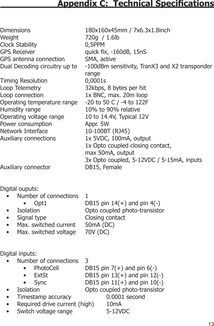
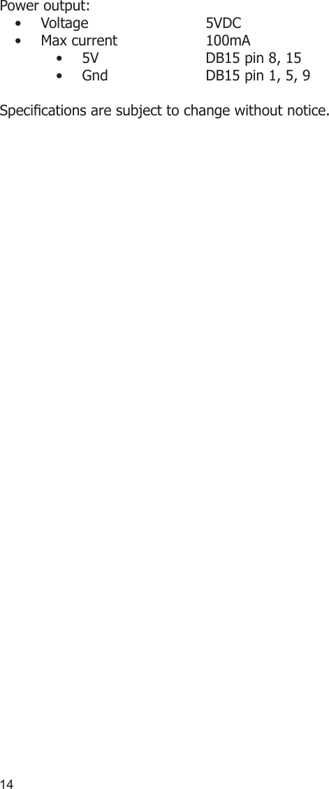
MYLAPS X2DECODER X2 Decoder User Manual Manual
MYLAPS BV X2 Decoder Manual
UserManual.wiki
>
MYLAPS
>
X2DECODER User Manual
Manual
Navigation menu
Upload a User Manual
Namespaces
Wiki Guide
HTML
PDF
Info
Views
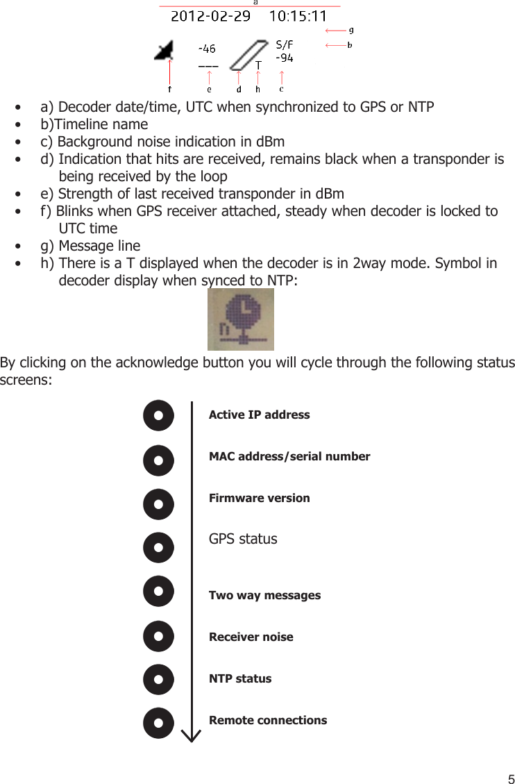
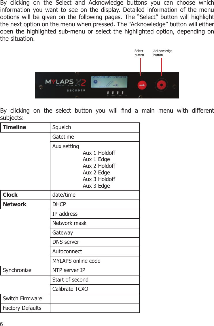
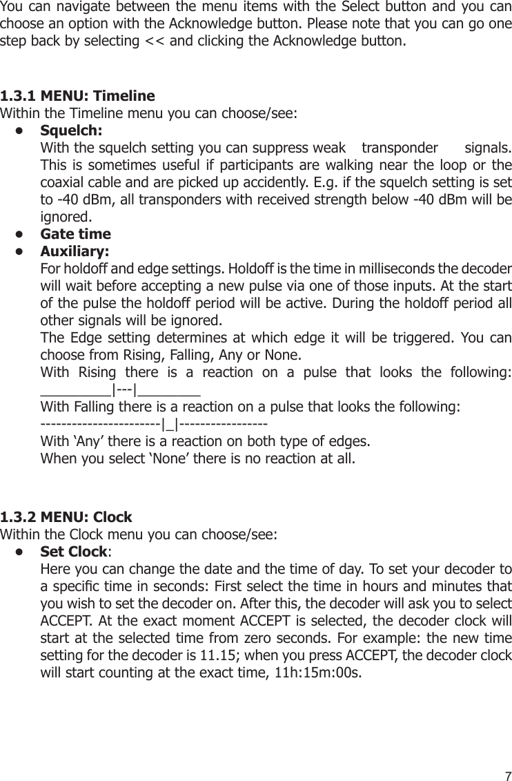
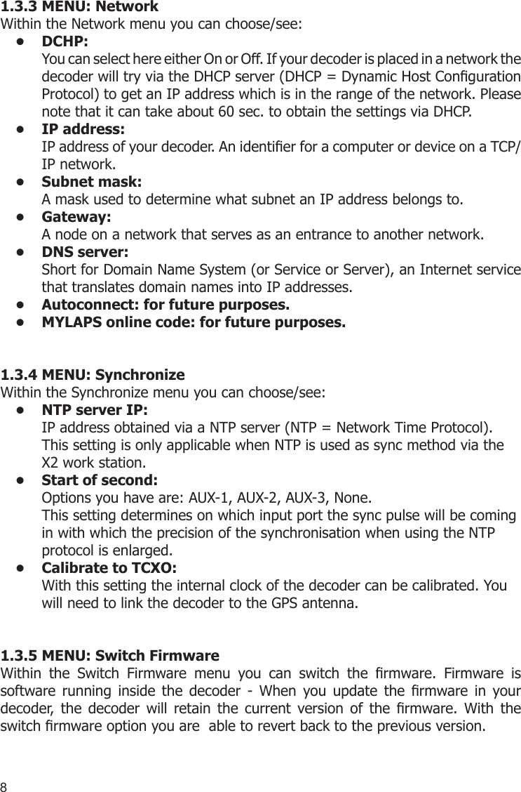
User Manual
Discussion / Help
Navigation