Manual

1
Contents
CONTACT INFORMATION..........................................
1. DECODER INSTALLATION/OPERATION................
1.1 Installation of the decoder.................................
1.2 Operating the MYLAPS X2 decoder......................
1.2.1 Noise level...............................................
1.2.2 Signal Strength........................................
1.3 Menu options explained.....................................
1.3.1 MENU: Timeline.......................................
1.3.2 MENU: Clock............................................
1.3.3 MENU: Network.......................................
1.3.4 MENU: Synchronize..................................
1.3.5 MENU: Switch Firmware...........................
1.3.6 MENU: Factory defaults.............................
APPENDIX A - FAQs........................................................
APPENDIX B - CE AND FCC REGULATIONS.......................
APPENDIX C - TECHNICAL SPECIFICATIONS....................
GUARANTEES & WARRANTIES.........................................
2
3
3
4
4
4
4
7
7
8
8
8
9
10
12
13
15

2
Contact Information
MYLAPS EMEA Ofce MYLAPS Americas Ofce
Haarlem Atlanta
The Netherlands USA
Tel: +31 23 7600 100 Tel: +1 678 816 4000
E-mail: info@mylaps.com E-mail: info.americas@mylaps.com
MYLAPS Japan Ofce MYLAPS Asia Pacic Ofce
Tokyo Sydney
Japan Australia
Tel: +81 3 5275 4600 Tel: +61 2 9546 2606
Email: info.japan@mylaps.com Email: info.asia.pacic@mylaps.com
MYLAPS Asia Ofce
Kuala Lumpur
Malaysia
Tel: +60 356131235
Email: info.asia@mylaps.com
www.mylaps.com
All rights reserved
Copyright © 2011-2013 MYLAPS
This publication has been written with great care. However, the manufacturer
cannot be held responsible, either for any errors occurring in this publication or
for their consequences.
The sale of products, services of goods governed under this publication are covered
by MYLAPS’s standard Terms and Conditions of Sales and this product manual is
provided solely for informational purposes. This publication is to be used for the
standard model of the product of the type given on the cover page.
MYLAPS Manual: MYLAPS X2 Decoder/2013-11
3
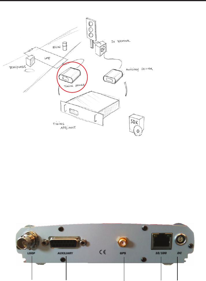
1: Decoder Installation/Operation
Figure 1.1 System overview
1.1 Installation of the decoder
The MYLAPS X2 decoder is a precision instrument. Therefore please handle it
with care and keep the MYLAPS X2 decoder out of direct sunlight and avoid high
humidity. Take special precautions in case of thunderstorms by disconnecting all
cables (coax, Ethernet and mains) from the MYLAPS X2 decoder. Nearby lightning
strikes can damage the decoder when these cables are connected.
Setting up and operating the MYLAPS X2 decoder may only be done by certied
professionals.
a) b) d) e)
c)
Figure 1.2 Connections of the decoder
4
How to connect
a) The detection loop: Connect the supplied 75 Ohmdouble-shielded coax •
cable to the MYLAPS X2 decoder.
b)The auxiliary port: This port can be used to connect a photocell, external •
start pulse or a sync pulse. For more information on how to connect these
devices, see appendix D.
c) The GPS antenna: Connect the GPS antenna cable and place the antenna •
where it has a clear view of the sky overhead to be able to make
connections to satellites
d) The network: This port can be used to connect the network cable •
between the decoder and the network connection port of the computer.
e) Power: Connect the supplied VDC adapter to the decoder and mains. •
It is recommended to connect the VDC adapter to mains through an
Uninterruptable Power Supply (UPS) to avoid any interruption of power
supply to the decoder.
1.2 Operating the MYLAPS X2 decoder
The decoder is not equipped with an on/off switch, therefore connecting the
decoder to the mains will switch it on. This will enable timing of transponder
passings after approximately 15 seconds. With each detection of a transponder
the received transponder information is shown on the decoder display.
1.2.1 Noise level
The decoder determines the average background noise. Noise level should not
exceed -85 dBm. If the noise level is higher, the received transponder signal
strength should be at least 20 dBm above noise level to ensure proper functioning
of the system. So if the transponder received signal strength is -55 dBm, the
noise should not exceed -75 dBm.
1.2.2 Signal strength
Transponder signal strength should preferably be above -65 dBm and should at
least be 20 dBm higher than the indicated background noise. The closer the
transponder is to the track, the higher the received signal strength will be. A
higher transponder signal strength should allow for greater immunity against
outside interference.
1.3 Menu options explained
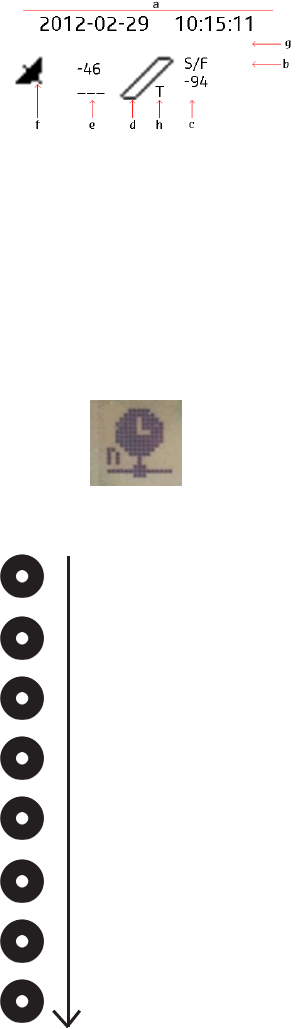
On the front of the decoder, you will nd an information display designed to
view and change the decoder settings. The status screen will show the following
information:
5
a) Decoder date/time, UTC when synchronized to GPS or NTP•
b)Timeline name•
c) Background noise indication in dBm•
d) Indication that hits are received, remains black when a transponder is •
being received by the loop
e) Strength of last received transponder in dBm•
f) Blinks when GPS receiver attached, steady when decoder is locked to •
UTC time
g) Message line•
h) There is a T displayed when the decoder is in 2way mode. Symbol in •
decoder display when synced to NTP:
By clicking on the acknowledge button you will cycle through the following status
screens:
Active IP address
MAC address/serial number
Firmware version
GPS status
Two way messages
Receiver noise
NTP status
Remote connections
6
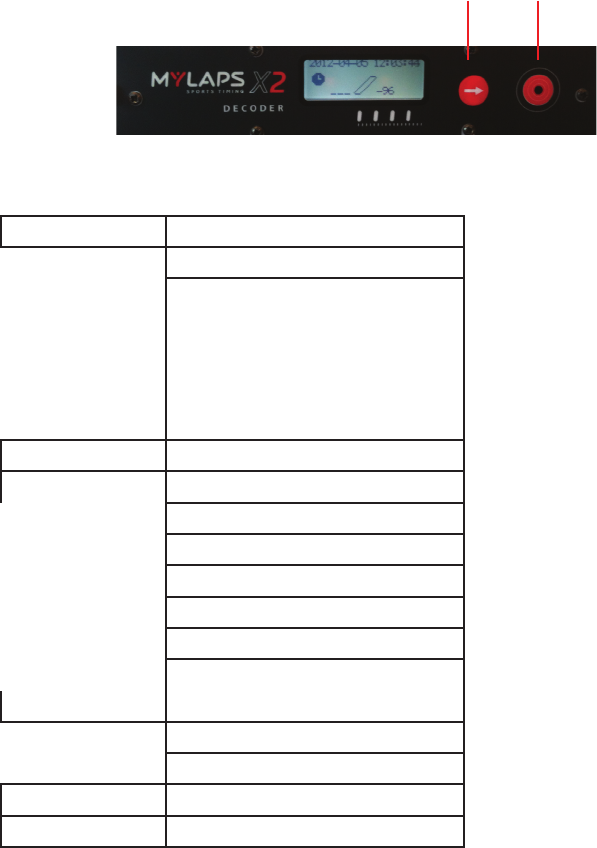
By clicking on the Select and Acknowledge buttons you can choose which
information you want to see on the display. Detailed information of the menu
options will be given on the following pages. The “Select” button will highlight
the next option on the menu when pressed. The “Acknowledge” button will either
open the highlighted sub-menu or select the highlighted option, depending on
the situation.
Select
button
Acknowledge
button
By clicking on the select button you will nd a main menu with different
subjects:
Timeline Squelch
Gatetime
Aux setting
Aux 1 Holdoff
Aux 1 Edge
Aux 2 Holdoff
Aux 2 Edge
Aux 3 Holdoff
Aux 3 Edge
Clock date/time
Network DHCP
IP address
Network mask
Gateway
DNS server
Autoconnect
MYLAPS online code
Synchronize NTP server IP
Start of second
Calibrate TCXO
Switch Firmware
Factory Defaults
7
You can navigate between the menu items with the Select button and you can
choose an option with the Acknowledge button. Please note that you can go one
step back by selecting << and clicking the Acknowledge button.
1.3.1 MENU: Timeline
Within the Timeline menu you can choose/see:
Squelch: •
With the squelch setting you can suppress weak transponder signals.
This is sometimes useful if participants are walking near the loop or the
coaxial cable and are picked up accidently. E.g. if the squelch setting is set
to -40 dBm, all transponders with received strength below -40 dBm will be
ignored.
Gate time•
Auxiliary:•
For holdoff and edge settings. Holdoff is the time in milliseconds the decoder
will wait before accepting a new pulse via one of those inputs. At the start
of the pulse the holdoff period will be active. During the holdoff period all
other signals will be ignored.
The Edge setting determines at which edge it will be triggered. You can
choose from Rising, Falling, Any or None.
With Rising there is a reaction on a pulse that looks the following:
_________|---|________
With Falling there is a reaction on a pulse that looks the following:
-----------------------|_|-----------------
With ‘Any’ there is a reaction on both type of edges.
When you select ‘None’ there is no reaction at all.
1.3.2 MENU: Clock
Within the Clock menu you can choose/see:
Set Clock• :
Here you can change the date and the time of day. To set your decoder to
a specic time in seconds: First select the time in hours and minutes that
you wish to set the decoder on. After this, the decoder will ask you to select
ACCEPT. At the exact moment ACCEPT is selected, the decoder clock will
start at the selected time from zero seconds. For example: the new time
setting for the decoder is 11.15; when you press ACCEPT, the decoder clock
will start counting at the exact time, 11h:15m:00s.
8
1.3.3 MENU: Network
Within the Network menu you can choose/see:
DCHP:•
You can select here either On or Off. If your decoder is placed in a network the
decoder will try via the DHCP server (DHCP = Dynamic Host Conguration
Protocol) to get an IP address which is in the range of the network. Please
note that it can take about 60 sec. to obtain the settings via DHCP.
IP address: •
IP address of your decoder. An identier for a computer or device on a TCP/
IP network.
Subnet mask: •
A mask used to determine what subnet an IP address belongs to.
Gateway: •
A node on a network that serves as an entrance to another network.
DNS server:•
Short for Domain Name System (or Service or Server), an Internet service
that translates domain names into IP addresses.
Autoconnect: for future purposes.•
MYLAPS online code: for future purposes.•
1.3.4 MENU: Synchronize
Within the Synchronize menu you can choose/see:
NTP server IP:•
IP address obtained via a NTP server (NTP = Network Time Protocol).
This setting is only applicable when NTP is used as sync method via the
X2 work station.
Start of second:•
Options you have are: AUX-1, AUX-2, AUX-3, None.
This setting determines on which input port the sync pulse will be coming
in with which the precision of the synchronisation when using the NTP
protocol is enlarged.
Calibrate to TCXO:•
With this setting the internal clock of the decoder can be calibrated. You
will need to link the decoder to the GPS antenna.
1.3.5 MENU: Switch Firmware
Within the Switch Firmware menu you can switch the rmware. Firmware is
software running inside the decoder - When you update the rmware in your
decoder, the decoder will retain the current version of the rmware. With the
switch rmware option you are able to revert back to the previous version.
9
1.3.6 MENU: Factory defaults
Within the Factory defaults menu you can reset to the factory defaults. This means
that you can reset the settings of the decoder to the initial settings.

10
Appendix A : FAQs
A1: Transponder is not being detected
A few transponders are not being detected.
If this is the case, the problem is most likely related to the individual transponder
or the positioning of the transponder.
- Check the mounting position of the transponder, for more information
check your transponder manual.
None of the transponders are being detected.
If this is the case, the problem is most likely related to the detection loop,
decoder, timing computer or cabling. Please take the following steps:
- Check if the loop in the display changes to black during a transponder
passing. If this is working, but nothing appears on the computer screen,
check the cabling between the decoder and the computer.
- Check the coaxial cable by measuring the resistance (with multimeter)
between the center pin and the outside of the BNC connector. The reading
should be approximately 100 kOhm after 30 seconds. If not, the coaxial
must be replaced.
- Check the loop wire by cutting the loop wires from the connection box
and measuring the resistance between the loop wires in the track. The
reading should be approximately 470 Ohm. If this is not the case, the loop
must be replaced. When (re)connecting the loopwires to the connection
box please solder with proper connections (for more information please
check your system installation manual).
Error messages
- Activator overload: This means that the overcurrent protection of the
activation circuit is working. A possible cause is a short circuit in the
coaxial cable, or the use of an incorrect loop or connection box.
- Activator hot: This means that the temperature of the activator circuit
is too high. The decoder must be used at ambient temperatures below
50C/122F, otherwise problems with the loop may occur.
11
A2: Noise level
What if my background noise is higher than -50 dBm?
An increased background noise is an indication of a higher interference level
picked up by the system. The noise level should be as low as possible, but as
long as the received signal from the transponders is at least 20 dBm higher then
the noise level detection will be reliable. If the noise level is higher than -70 dBm,
there is most likely something wrong with the installation.
Possible causes of high background noise levels:
When the detection loop is damaged, a uctuation in noise level will be •
noticeable, especially in wet conditions. If this is the case, please check
the loop wire and coaxial for cuts or breakage.
Electrical equipment too close (<3 m) to the loop or coaxial cable.•
Using a generator with a poor ground connection•
Use of DC/AC converter for AC power.•
Poor connections between the detection loop and the coaxial cable.•
BNC connector incorrectly tted to the coaxial cable•
Poor ground connection of the AC power. •
A3: Signal strength
What if the received signal strength is below -65 dBm?
If the signal strength is lower than -65 dBm, please check the position of •
the transponder.
If the signal strength is uctuating heavily in combination with high noise •
levels, check the qualityof the loop installation and coaxial cables.

12
Appendix B: CE and FCC Regulations
CE information:
This device complies with the EMC directive 89/336/EEC. A copy of the declaration
oconformity can be obtained at:
MYLAPS Sports Timing
Zuiderhoutlaan 4
2012 PJ Haarlem
The Netherlands
FCC-ID: NXYX2DECODER
Compliance statement (part 15.19)
This device complies with part 15 of the FCC Rules. Operation is subject to the following
two conditions:
this device may not cause harmful interference, and1.
this device must accept any interference received, including interference that may 2.
cause undesired operation.
Warning (part 15.21)
Changes or modications not expressly approved by the party responsible for compliance
could void the user’s authority to operate the equipment.
Information to the User (Part 15.105 (b))
Note: This equipment has been tested and found to comply with the limits for a Class
B digital device, pursuant to part 15 of the FCC Rules. These limits are designed to
provide reasonable protection against harmful interference in a residential installation.
This equipment generates, uses and can radiate radio frequency energy and, if not
installed and used in accordance with the instructions, may cause harmful interference
to radio communications. However, there is no guarantee that interference will not occur
in a particular installation. If this equipment does cause harmful interference to radio
or television reception, which can be determined by turning the equipment off and on,
the user is encouraged to try to correct the interference by one or more of the following
measures:
Reorient or relocate the receiving antenna.•
Increase the separation between the equipment and receiver.•
Connect the equipment into an outlet on a circuit different from that to which the •
receiver is connected.
Consult the dealer or an experienced radio/TV technician for help.•

13
Appendix C: Technical Specications
Dimensions 180x160x45mm / 7x6.3x1.8inch
Weight 720g / 1.6lb
Clock Stability 0,5PPM
GPS Receiver quick x, -160dB, 15nS
GPS antenna connection SMA, active
Dual Decoding circuitry up to -100dBm sensitivity, TranX3 and X2 transponder
range
Timing Resolution 0,0001s
Loop Telemetry 32kbps, 8 bytes per hit
Loop connection 1x BNC, max. 20m loop
Operating temperature range -20 to 50 C / -4 to 122F
Humidity range 10% to 90% relative
Operating voltage range 10 to 14.4V, Typical 12V
Power consumption Appr. 5W
Network Interface 10-100BT (RJ45)
Auxiliary connections 1x 5VDC, 100mA, output
1x Opto coupled closing contact,
max 50mA, output
3x Opto coupled, 5-12VDC / 5-15mA, inputs
Auxiliary connector DB15, Female
Digital ouputs:
Number of connections 1•
Opt1 DB15 pin 14(+) and pin 4(-)•
Isolation Opto coupled photo-transistor•
Signal type Closing contact•
Max. switched current 50mA (DC)•
Max. switched voltage 70V (DC)•
Digital inputs:
Number of connections 3•
PhotoCell DB15 pin 7(+) and pin 6(-)•
ExtSt DB15 pin 13(+) and pin 12(-)•
Sync DB15 pin 11(+) and pin 10(-)•
Isolation Opto coupled photo-transistor•
Timestamp accuracy 0.0001 second•
Required drive current (high) 10mA•
Switch voltage range 5-12VDC•
14
Power output:
Voltage 5VDC•
Max current 100mA•
5V DB15 pin 8, 15•
Gnd DB15 pin 1, 5, 9•
Specications are subject to change without notice.

15
Guarantees & Warranties
MYLAPS warrants that, for a period of three (3) years from the date of shipping the decoders and the
MYLAPS MX Rechargeable Power, MYLAPS RC DP, MYLAPS KART DP, MYLAPS Kart Rechargeable Power,
MYLAPS Car/Bike DP, MYLAPS Car/Bike Rechargeable Power, MYLAPS Car/Bike Pro transponders,
MYLAPS X2 transponder covered by this warranty with defects, as determined solely by MYLAPS,
caused by faulty materials, workmanship or design will be repaired or replaced, unless such defects
were the result of any of the following: shipping; improper installation, maintenance or use; abnormal
conditions of operation; attempted modication or repair by the customer or any third party; use of
the goods in combination with other items; or an act of God. If repair or replacement of the goods is
not possible or economical for MYLAPS, MYLAPS may, at its option, refund the purchase price of the
goods or deliver replacement goods at its sole discretion. MYLAPS’s liability shall be strictly limited to
replacing, repairing or issuing credits at its option.
MYLAPS warrants that, for a period of two (2) years from the date of shipping the ProChip, MYLAPS
Kart Fixed Power and the MYLAPS RC Rechargeable Power transponders covered by this warranty with
defects, as determined solely by MYLAPS, caused by faulty materials, workmanship or design will be
repaired or replaced, unless such defects were the result of any of the following: shipping; improper
installation, maintenance or use; abnormal conditions of operation; attempted modication or repair
by the customer or any third party; use of the goods in combination with other items; or an act of
God. If repair or replacement of the goods is not possible or economical for MYLAPS, MYLAPS may, at
its option, refund the purchase price of the goods or deliver replacement goods at its sole discretion.
MYLAPS’s liability shall be strictly limited to replacing, repairing or issuing credits at its option.
MYLAPS warrants that, for a period of one (1) year from the date of shipping the MYLAPS Onboard
Display kit covered by this warranty with defects, as determined solely by MYLAPS, caused by faulty
materials, workmanship or design will be repaired or replaced, unless such defects were the result
of any of the following: shipping; improper installation, maintenance or use; abnormal conditions of
operation; attempted modication or repair by the customer or any third party; use of the goods in
combination with other items; or an act of God. If repair or replacement of the goods is not possible
or economical for MYLAPS, MYLAPS may, at its option, refund the purchase price of the goods or
deliver replacement goods at its sole discretion. MYLAPS’s liability shall be strictly limited to replacing,
repairing or issuing credits at its option.
MYLAPS warrants that, for a period of one (1) year from the date of shipping, all other goods
covered by this warranty with defects, as determined solely by MYLAPS, caused by faulty materials,
workmanship or design will be repaired or replaced, unless such defects were the result of any of
the following: shipping; improper installation, maintenance or use; abnormal conditions of operation;
attempted modication or repair by the customer or any third party; use of the goods in combination
with other items; or an act of God. If repair or replacement of the goods is not possible or economical
for MYLAPS, MYLAPS may, at its option, refund the purchase price of the goods or deliver replacement
goods at its sole discretion. MYLAPS’s liability shall be strictly limited to replacing, repairing or issuing
credits at its option.
If the requirements set forth above and described under Remedies and Damages are not complied
with, our warranty/guarantee shall not apply and we shall be discharged from all liability arising from
the supply of defective goods.
EXCEPT AS EXPRESSLY PROVIDED IN THIS SECTION, MYLAPS MAKES NO REPRESENTATIONS
OR WARRANTIES OF ANY KIND, NATURE OR DESCRIPTION, EXPRESS OR IMPLIED, INCLUDING
WITHOUT LIMITATION, ANY WARRANTY OR MERCHANTABILITY, FITNESS OF THE GOODS FOR ANY
PARTICULAR PURPOSE, OR NONINFRINGEMENT, AND MYLAPS HEREBY DISCLAIMS THE SAME.
16
Remedies and Damages
1. MYLAPS shall not incur any liability under the above warranty unless:
i) MYLAPS is promptly notied in writing upon discovery by the customer that such goods do not
conform to the warranty, and the appropriate invoice number and date of purchase information is
supplied;
ii) The alleged defective goods are returned to MYLAPS carriage pre-paid;
iii) Examination by MYLAPS of goods shall conrm that the alleged defect exists and has not been
caused by unauthorized use (including, without limitation, the use of an AMB decoder with non-
MYLAPS hardware) misuse, neglect, method of storage, faulty installation, handling, or by alteration
or accident; and
iv) With respect to MYLAPS decoders, customer has upgraded the rmware in its decoder within one
month after MYLAPS has offered to provide customer with such upgraded rmware.
2. The customer acknowledges that the goods may include certain rmware imbedded therein. MYLAPS
hereby grants a license to customer to use the imbedded rmware in an MYLAPS decoder, but only to
the extent the decoder is used in connection with MYLAPS hardware. MYLAPS shall have the right to
terminate the license immediately upon written notice to customer in case MYLAPS has a reasonable
belief that customer at any time has used the MYLAPS decoder in connection with non-AMB hardware.
Further, customer may not copy, compile, reverse compile, disassemble, translate, analyze, reverse
engineer or attempt to reverse engineer the rmware, except as permitted by applicable law.
3. In addition, customer grants MYLAPS the option to repurchase any MYLAPS decoder if MYLAPS
has a reasonable belief that customer has used the MYLAPS decoder in connection with non-MYLAPS
hardware. The repurchase price shall be the fair market value on the date MYLAPS provides notice to
customer that it intends to repurchase the decoder.
The above mentioned warranty/guarantee is irrespective of any rights granted to the buyer of MYLAPS
equipment manufactured or sold by MYLAPS based on the laws of the Netherlands. Any correspondence
regarding the above mentioned guarantee must be addressed to MYLAPS:
MYLAPS EMEA OFFICE HAARLEM
Zuiderhoutlaan 4
2012 PJ HAARLEM
THE NETHERLANDS
E-mail: info@mylaps.com
Fax: +31 23 529 0156