Machine Technology RAPNASMF Network audio system (built-in amplifier) User Manual RAPNAS MF 1
Machine Technology (SZ) Co., Ltd. Network audio system (built-in amplifier) RAPNAS MF 1
UserManual.wiki
>
Machine Technology
>
RAPNASMF User Manual
User manual
Navigation menu
Upload a User Manual
Namespaces
Wiki Guide
HTML
PDF
Info
Views
User Manual
Discussion / Help
Navigation

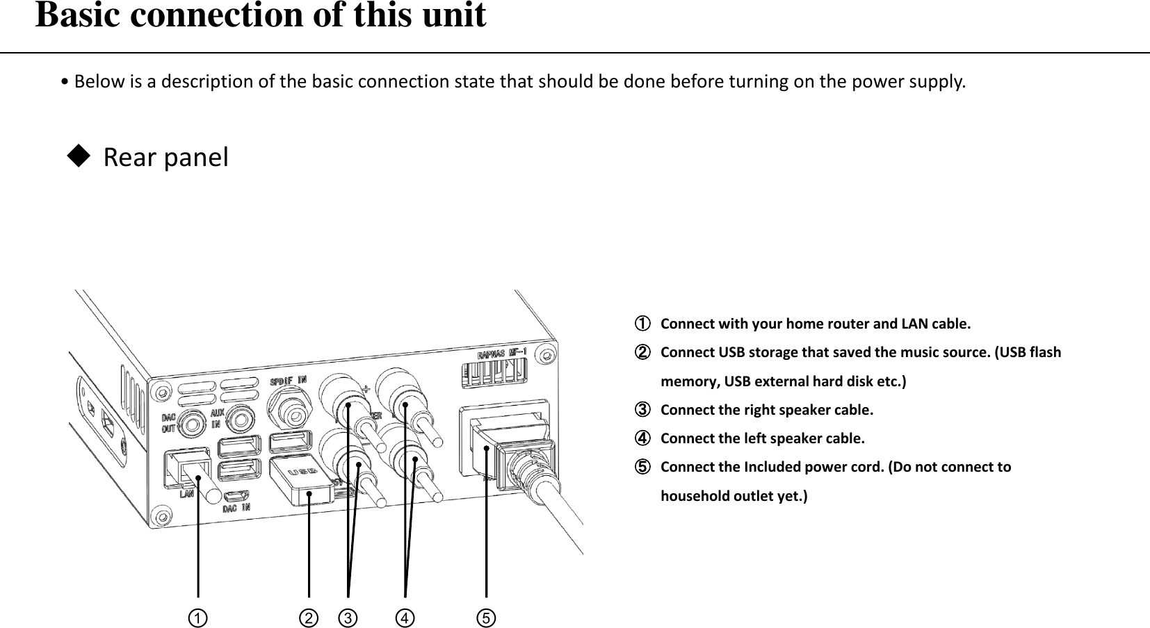
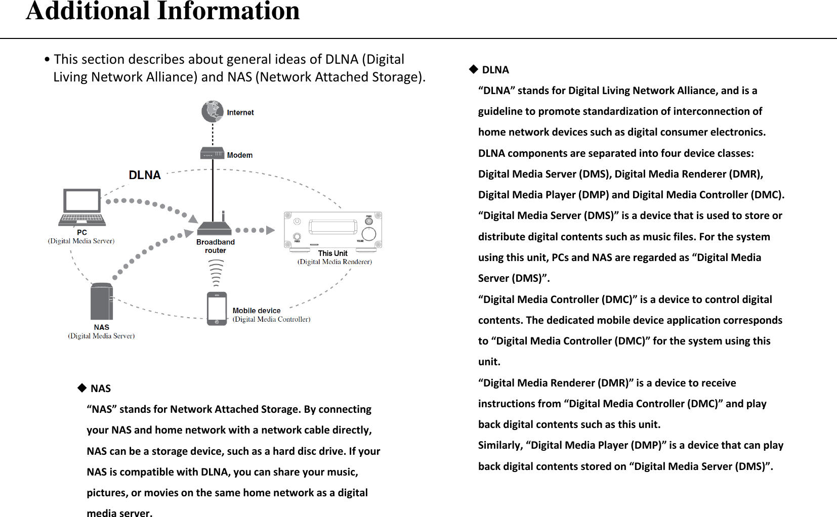
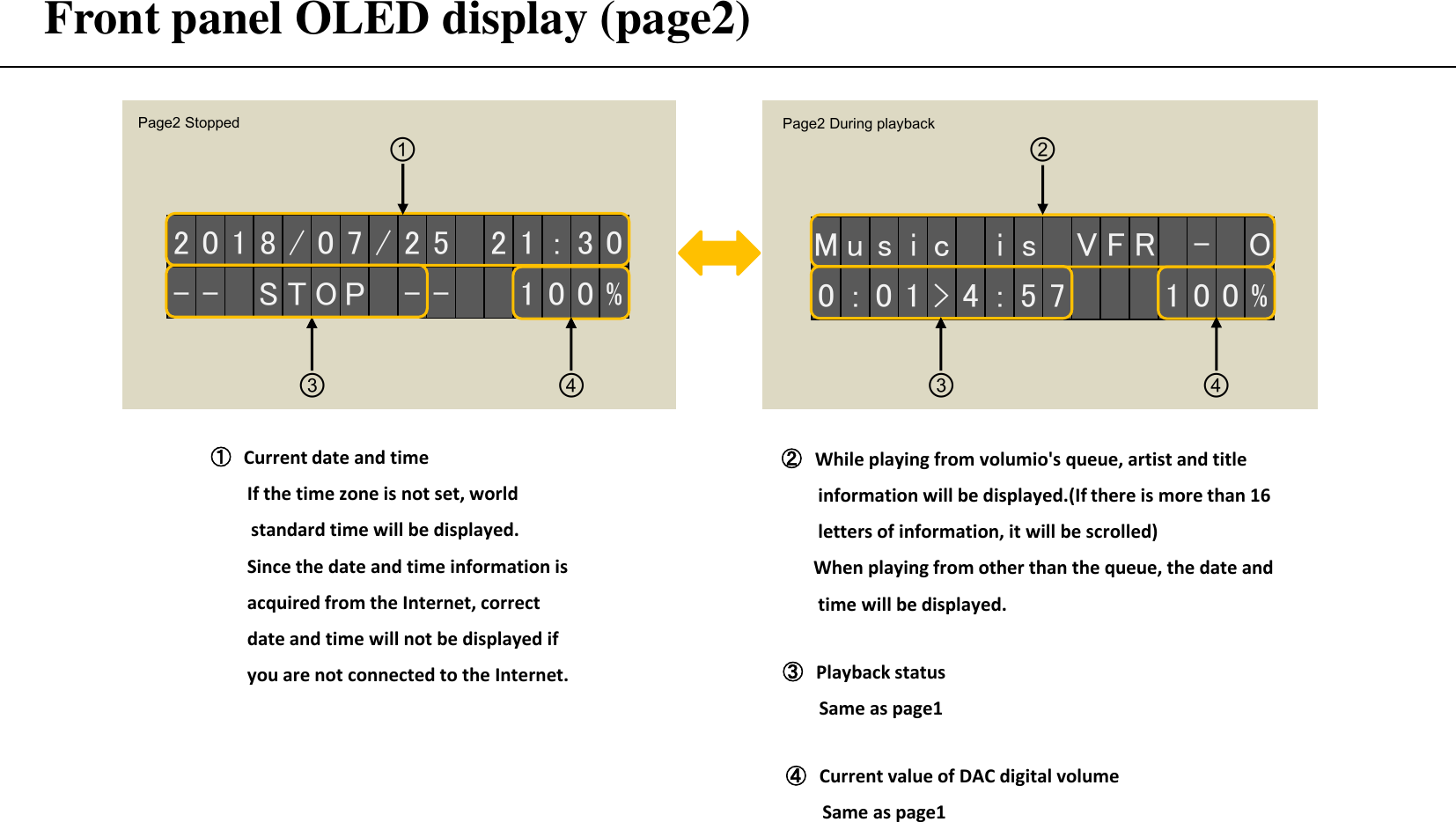
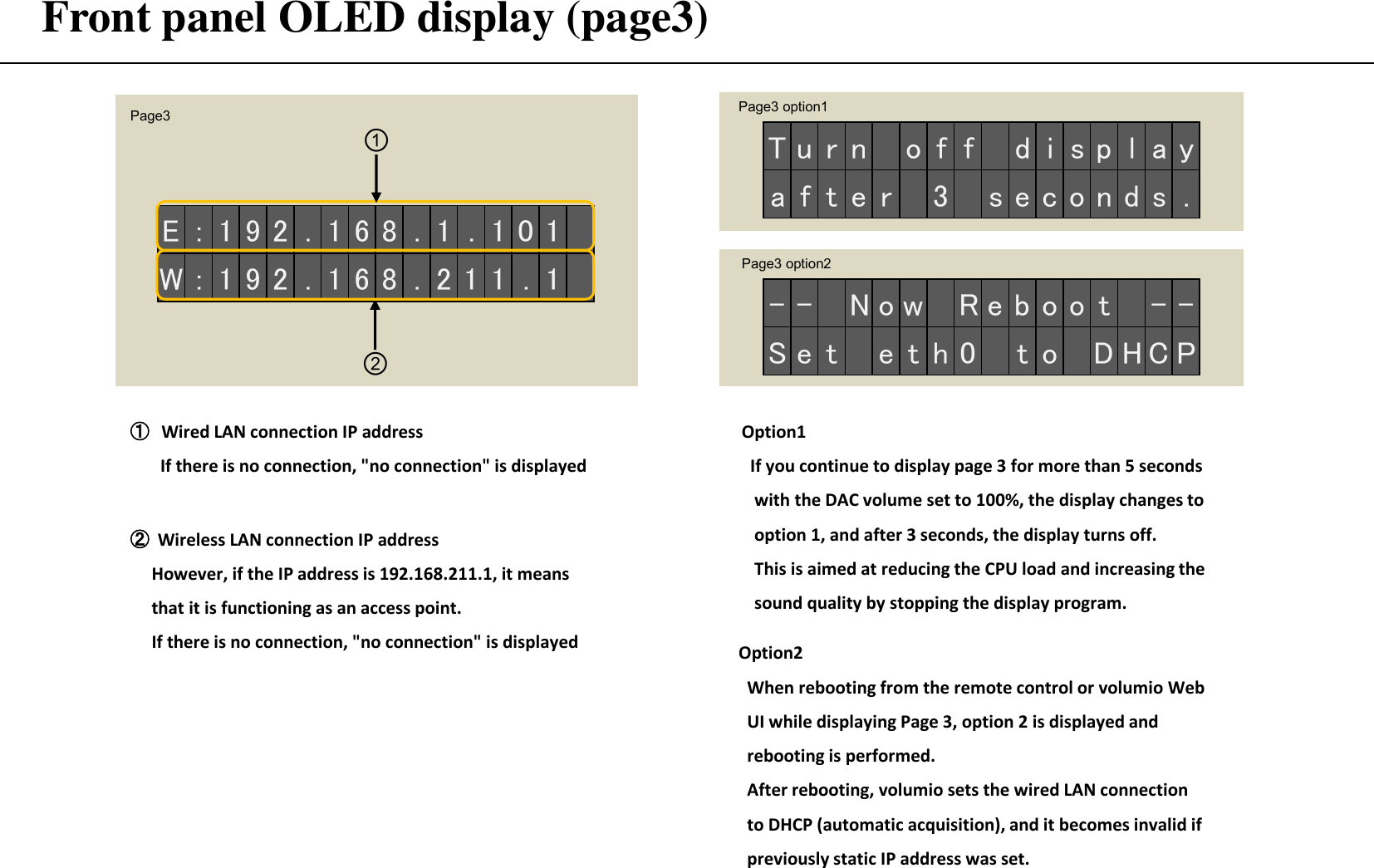
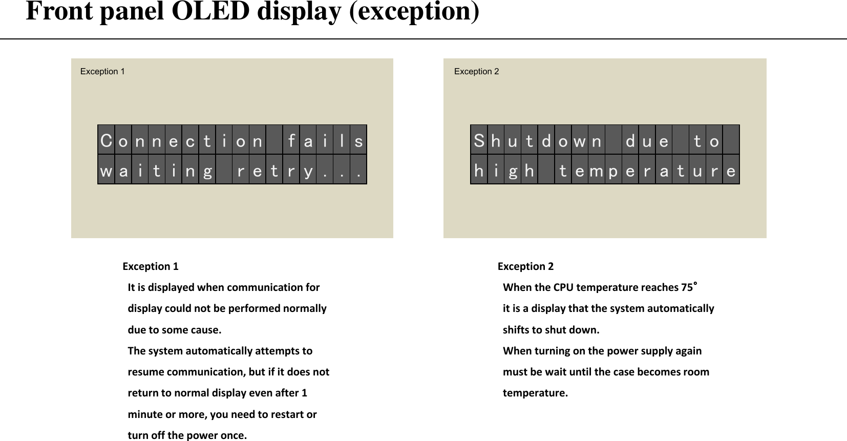
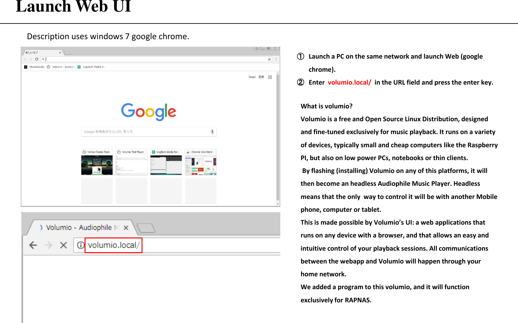
![Front panel OLED display (page1) • The display content of the front panel is the structure of 3 pages, the first page is displayed at the beginning. The page switches from 1 → 2 → 3 → 1 each time "Change display button" on the attached remote control is pressed. Page1 Stopped ④ [ P CM- 1 ] 4 4 . 1 K H z0 : 1 2 > 4 : 0 8 1 0 0 %② ③ ⑤ ①DAC mode (Release Mode): When USB-DAC is released (USB-DAC Mode): Set RAPNAS USB-DAC in volumio (I2S-DAC Mode): Set RAPNAS I2S-DAC in volumio ③ Sampling rate PCM-1: Support 44.1KHz-384KHz PCM-2: Support 44.1KHz-768KHz PCM-3: Support 44.1KHz-768KHz DSD-2: Support DSD64-DSD512 DoP-2: Support DSD64-DSD256 DSD-3: Support DSD64-DSD256 SPDIF: Support 44.1KHz-192KHz X:XX>X:XX or X:XX!X:XX : When volumio playing music from the queue, that time is displayed. ・When the middle mark is > : During playback ・When the middle mark is ! : Paused ・Left term is playing time, right term is ending time -- LINK --: When playing from other than the queue, will be displayed. ⑤ Current value of DAC digital volume 0 to 100% (-127 to 0dB) ( R e l e a s e Mo d e )- - S T O P - - 1 0 0 %① ④ ⑤ ④ Playback status -- STOP --: Stopped Page1 During playback ② Format and DAC input stream PCM-1: I2S direct input of PCM PCM-2: Input via USB-DAC of PCM PCM-3: External PCM input to USB-DAC DSD-2: Input via USB-DAC of DSD DoP-2: Input via USB-DAC of DoP DSD-3: External DSD input to USB-DAC SPDIF: Direct input of SPDIF](https://usermanual.wiki/Machine-Technology/RAPNASMF/User-Guide-4110067-Page-22.png)
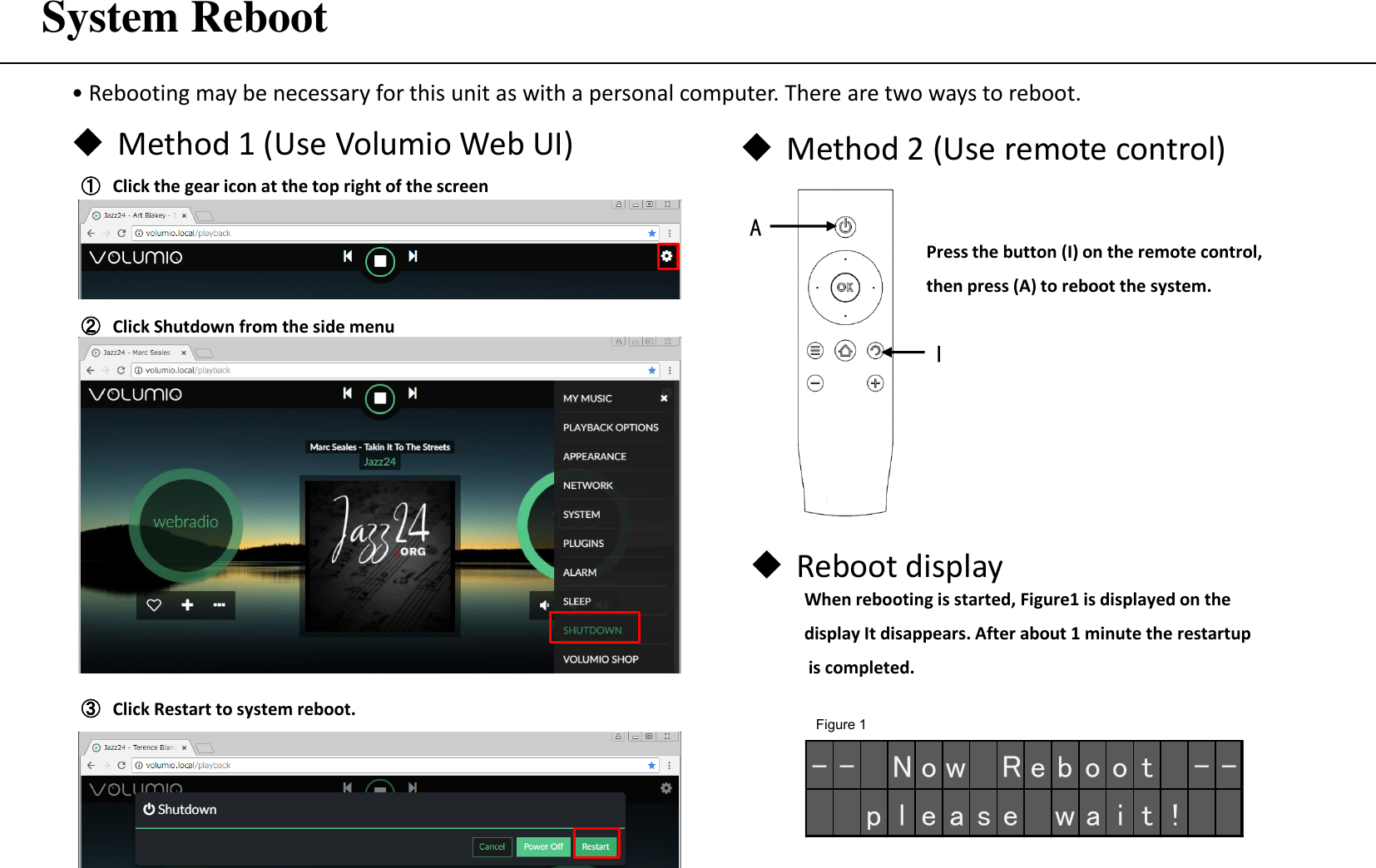
![Playback LR Stereo Test Item Function [Play]: When clicked, the title is added to the queue and playback starts.(You can do the same thing by directly clicking the title name) [Add to queue]: Add title to queue. [Clear and play]: The queue is first emptied, the title is added to the queue, and playback is started. [Add to Playlist]: Save the title to an arbitrary Playlist name. *1 [Add to Favorite]: Save the title to an favorites. *1 *1: The saved title can be selected from the Browse screen on the previous page. ① When you click the at the right end of the title "LR Channel And Phase" , the menu is displayed. Here we select ”Add to queue” ② When you return to the queue screen, a title has been added. ③ Click the title on the queue screen or move to the playback screen and click the to start playback. ...](https://usermanual.wiki/Machine-Technology/RAPNASMF/User-Guide-4110067-Page-30.png)
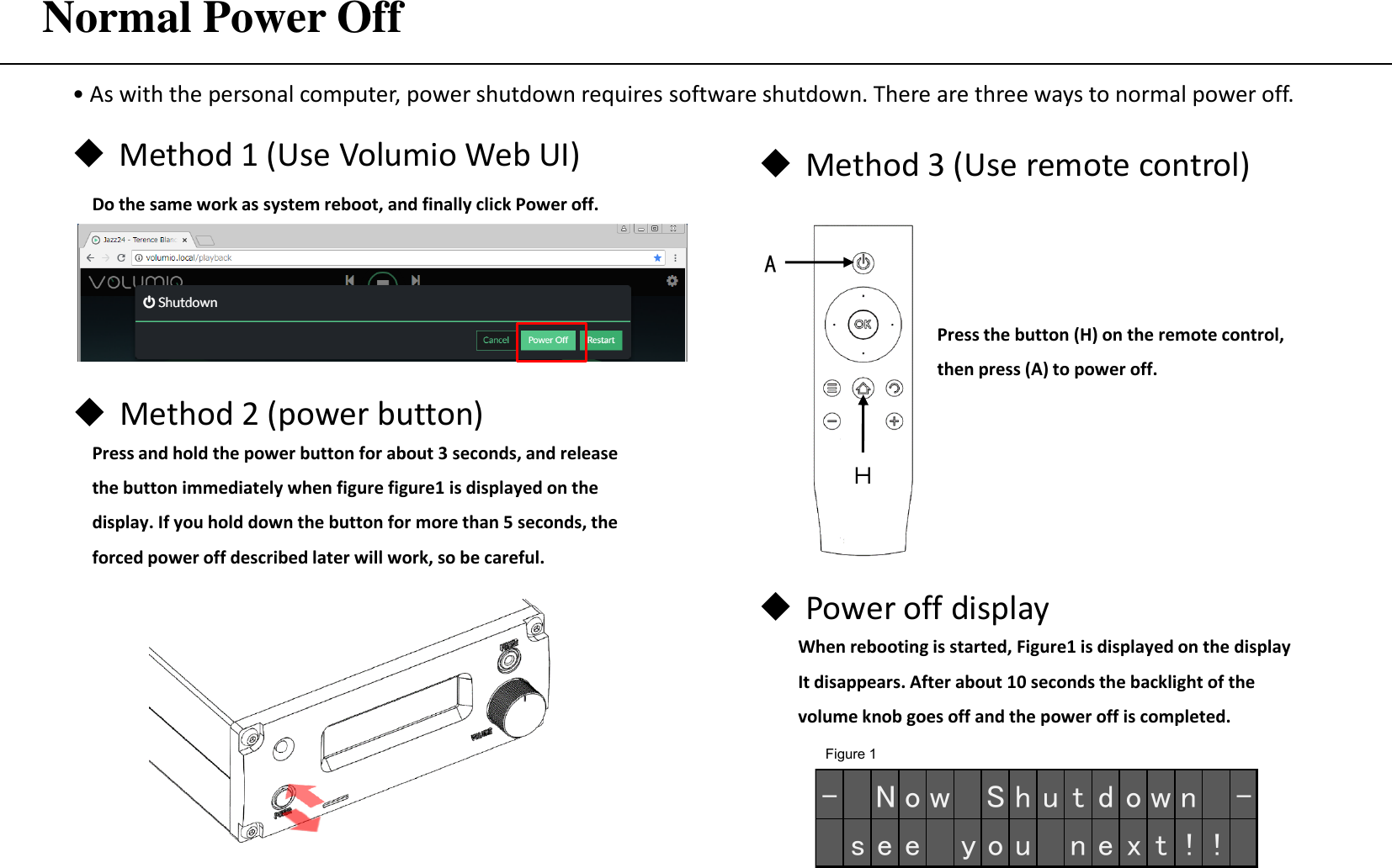
![DSD Native Playback ② Follow "Change DAC mode" on page 23 to switch the output device for the volumio playback option to RAPNAS USB-DAC. Preparation is completed when the following figure is displayed in the OLED. • In the case of performing native playback of DSD in Volumio, two preparations are required beforehand. Work should be done with playback stopped. USB conversion cable B ①Connect the rear panel DAC - IN and USB expansion port with the included USB conversion cable B. ( U S B - D A C Mo d e )- - S T O P - - 1 0 0 %Afterwards, it is only selecting and playing the sound source of DSD format with volumio. During DSD playback, the OLDE will display as shown below. [ D S D - 2 ] 1 1 . 2 8MH z0 : 3 2 > 5 : 0 8 1 0 0 %](https://usermanual.wiki/Machine-Technology/RAPNASMF/User-Guide-4110067-Page-32.png)
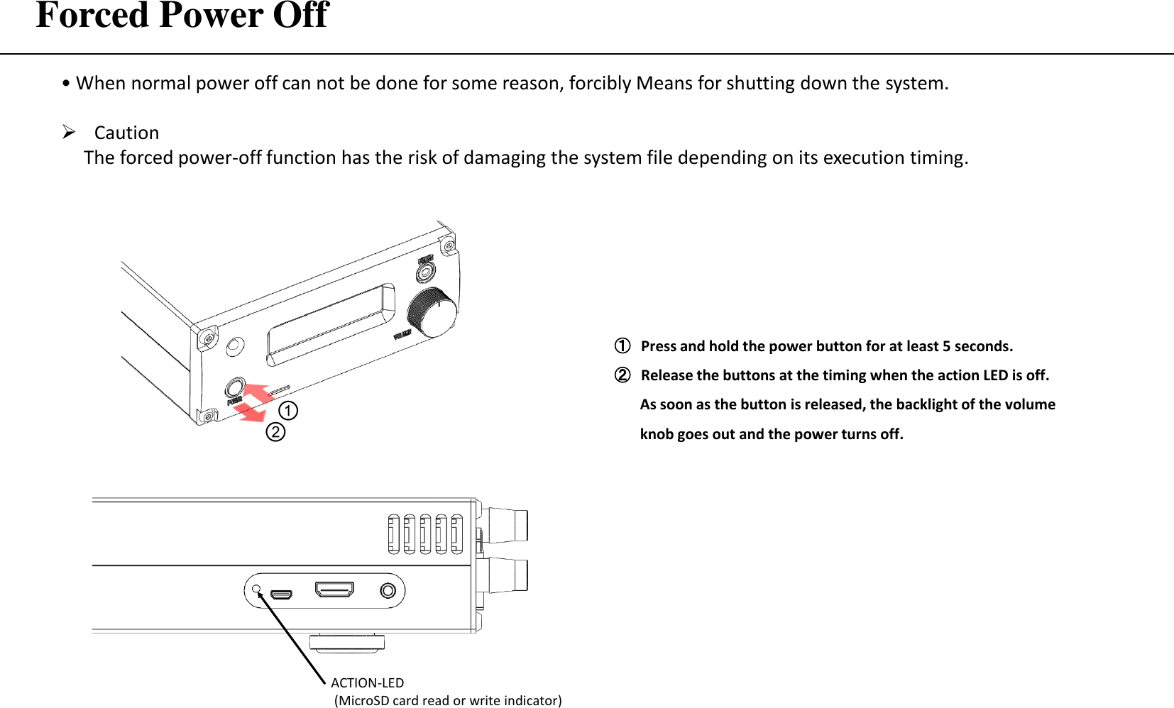
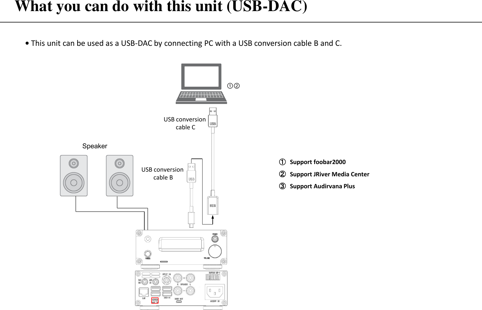
![Used as external player's USB-DAC • This unit can be used as a USB-DAC by connecting PC with a USB conversion cable B and C. About the USB driver You can use foobar2000 etc as playback software on the PC side, USB audio 2.0 driver is not installed on Windows 10 version 1703 or earlier OS. You will need to install the driver yourself as needed. For Mac OS, the driver is installed by default. ・As shown in the figure on the left, when connected to a personal computer and this unit is used as an external USB-DAC, the OLED being played back will be displayed as shown below. [ D S D - 3 ] 5 . 6 4MH z- - L I N K - - 1 0 0 %[ P CM- 3 ] 9 6 . 0 K H z- - L I N K - - 1 0 0 %During PCM playback During DSD playback ・In reproduction of the DSD of this connection, the output from the personal computer is the DoP format due to the nature of the driver, but the OLED display becomes DSD instead of DoP. The DSD rate that can be supported as DoP input in this unit is maximum, and it is up to DSD 256.](https://usermanual.wiki/Machine-Technology/RAPNASMF/User-Guide-4110067-Page-38.png)