Macro Image Technology MDP-100 HDTV Receiving PC Card User Manual MDP100 manual

Macro Image Technology, Inc HDTV Receiving PC Card MDP100 manual
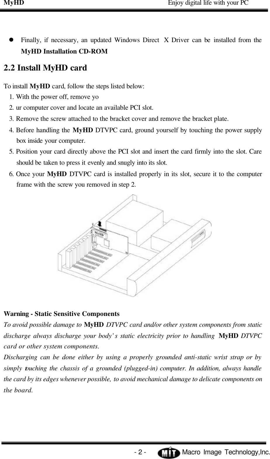
users manual

i  MyHD MDP-100 User’s Guide   version 0.9 May, 2001   HDTV PC Card  Enjoy digital life with your PC
ii FCC INFORMATION TO THE USER This equipment has been tested and found to comply with the limits for a Class B digital device, pursuant to part 15 of the FCC Rules. These limits are designed to provide reasonable protection against harmful interference in a residential installation. This equipment generates, uses and can radiate radio frequency energy and, if not installed and used in accordance with the instructions, may cause harmful interference to radio communications. However, there is no guarantee that interference will not occur in a particular installation. If this equipment does cause harmful interference to radio or television reception, which can be determined by turning the equipment off and on, the user is encouraged to try to correct the interference by one more of the following measures: -. Reorient or relocate the receiving antenna. -. Increase the separation between the equipment and receiver. -. Connect the equipment into an outlet on a circuit different from that to which the receiver is connected. -. Consult the dealer or an experienced radio/TV technician for help.  WARNING   Changes or modifications not expressly approved by the manufacturer could void the user’s authority to operate the equipment.
iii  Contents 1.System Requirements  -------------------------------------------------------   1 1.1 PC Platform Requirements  ------------------------------------------------   1 2. Hardware Installation ---------------------------------------------------------   1 2.1  Installation overview  ---------------------------------------------------------   1 2.2  Install  MyHD card  -------------------------------------------------------------   2 2.3  Connect  the Cables  ----------------------------------------------------------   3 2.4 Connecting the  MyHD board to a Sound Card  ----------------------   4 2.5 Install the MyHD driver for Windows  -------------------------------------   5 3. Quick Troubleshooting Guide ---------------------------------------------   7 4.  MyHD Application  ----------------------------------------------------------------   8 4.1  Application Installation  -----------------------------------------------------   8 4.2 Check lists before  running the  MyHD  ---------------------------------   8 4.3 User Interface Description  -------------------------------------------------   9 4.4 Remote Controller  ------------------------------------------------------   11 4.5 Channel Property Set  ------------------------------------------------  12 4.5.1  Auto Channel Scan    -----------------------------------------------------  12 4.5.2  Change Channel Configure    -----------------------------------------  12
iv 4.5.3  Add/Remove Favorite Channel    -------------------------------------  13 4.5  MyHD Envrionment Configuration  --------------------------------------  14 4.5.1  AV Setup Tab  -------------------------------------------------------  14 4.5.2  VGA Setup Options   ----------------------------------------------------  16 4.7  Pop-up Controls  ------------------------------------------------------------  17 4.8 Keyboard Shortcuts  ----------------------------------------------------------  17
v [blank]
MyHD                                             Enjoy digital life with your PC   - 1 -            Macro Image Technology,Inc. 1. SYSTEM REQUIREMENTS To achieve optimum performance of the  MyHD Board, your PC requires a minimum configuration. This chapter provides the system requirements. This chapter contains the following sections: 1.1 PC Platform Requirements The minimum requirements for you PC platform are listed below: CPU : Pentium-II 333MHz or faster DRAM : 64 Megabytes or Higher System Bus : PCI Operating System : Windows 98 Second Edition. , ME Other Software : DirectX Media 6.0 Runtime VGA : DirectX compatibility VGA card (8 MB memory or higher recommended) 2. HARDWARE INSTALLATION The MyHD boards are Plug-and-Play devices designed for Window 98SE and ME. Plug-and-Play simplifies the installation and hardware setup of  MyHD by having hardware settings assigned by Windows, instead of needing to set jumpers. This chapter describes how to install these boards and how the automated Plug-and-Play installation procedure works .  2.1 Installation overview To install MyHD under Windows 98SE or ME, you will follow these steps: l Install the MyHD board in your PC l After booting Windows, you will install  MyHD’s  Windows device driver from the MyHD Installation CD-ROM l After the Windows driver is installed, you will then install the MyHD application software from the MyHD Installation CD-ROM
MyHD                                             Enjoy digital life with your PC   - 2 -            Macro Image Technology,Inc. l Finally, if necessary, an updated Windows Direct  X Driver can be installed from the MyHD Installation CD-ROM 2.2 Install MyHD card To install MyHD card, follow the steps listed below: 1. With the power off, remove yo 2. ur computer cover and locate an available PCI slot. 3. Remove the screw attached to the bracket cover and remove the bracket plate. 4. Before handling the MyHD DTVPC card, ground yourself by touching the power supply box inside your computer. 5. Position your card directly above the PCI slot and insert the card firmly into the slot. Care should be taken to press it evenly and snugly into its slot. 6. Once your MyHD DTVPC card is installed properly in its slot, secure it to the computer frame with the screw you removed in step 2.  Warning - Static Sensitive Components To avoid possible damage to MyHD DTVPC card and/or other system components from static discharge always discharge your body’s static electricity prior to handling  MyHD DTVPC card or other system components. Discharging can be done either by using a properly grounded anti-static wrist strap or by simply touching the chassis of a grounded (plugged-in) computer. In addition, always handle the card by its edges whenever possible, to avoid mechanical damage to delicate components on the board.
MyHD                                             Enjoy digital life with your PC   - 3 -            Macro Image Technology,Inc. The following diagram shows the main functions and connectors of the MyHD board. Since there are several different models with different features and functions, your board may not have all of the components installed. <Figure 2.1> 2.3 Connect the Cables There are three basic cable configurations for MyHD  :  Dual Monitor, Single Monitor. The following subsections describe each operating configuration and their cabling connections. Please refer to A if you have two monitors, otherwise refer to B.    A. Dual Monitor Configuration <Figure 2.2>
MyHD                                             Enjoy digital life with your PC   - 4 -            Macro Image Technology,Inc. Figure2.2 shows the dual-monitor configuration. Video output from the MyHD board is displayed on a separate HDTV or VGA monitor, without being mixed with VGA graphics. The HDTV display monitor used should be capable of receiving RGB(HV separate sync) type or YPbPr(sync on Y) type with support of following horizontal frequency: 33.7kHz(1920x1080 interlaced), 44.9kHz(1280x720 progressive), 31.5kHz(720x480 progressive), 48.3kHz(1024x768 progressive), 15.75kHz(720x480 interlaced).  B. Single Monitor Configuration  <Figure 2.3> This configuration allows you to share a single monitor to display either VGA graphics or RGB video output by means of an analog switch. Figure 2.3 illustrates the cable connections used in this configuration. The VGA card display output is looped back into MyHD Board via its VGA loop-back input. An analog switch on the MyHD Board switches between the VGA loop-back input (default) and the MyHD HD video output.  2.4 Connecting the MyHD board to a Sound Card The MyHD board's audio output should be connected to a sound card using the supplied Audio Cable, refer to the figure 2.2 or 2.3 l Plug the other end of the Audio Cable into the LineIn port of your sound card.
MyHD                                             Enjoy digital life with your PC   - 5 -            Macro Image Technology,Inc. 2.5 Install the MyHD driver for Windows   . 1. When re-starting Windows for the first time after the MyHD board has been installed, the Add New Hardware Wizard will appear. Click NEXT..         2. Select  Search for the best driver for your device (Recommended). Click NEXT.         3. When you see this dialog box, insert the MyHD Windows Installation CD-ROM  into your CD-ROM drive.  Select  “Specify a location” and type “D:\Driver” or Browse the Driver irectory in your CD-ROM (Where “D” is the etter of your CD-ROM driver.) click NEXT.
MyHD                                             Enjoy digital life with your PC   - 6 -            Macro Image Technology,Inc. 4. Once the MyHD video driver has been detected. click NEXT  Note: If a message stating “Windows was unable to locate a driver for this device”, you did not wait long enough for the MyHD Installation CD-ROM to be read. Click  Back  and then click Next again for the CD to be recognized.   5. You will see a number of files being copied to your hard disk drive. If you receive an error message saying a file  can not be found, browse to the Driver directory on the MyHD Windows Installation CD-ROM  or Windows CD-ROM for these files.     6. Click Finish and Restart your computer.
MyHD                                             Enjoy digital life with your PC   - 7 -            Macro Image Technology,Inc. 3. QUICK TROUBLESHOOTING GUIDE l Incompatible motherboards We recommend the use of a motherboard with an Intel chipset because some other motherboards do not fully support the MyHD. l System lockups or error messages when running MyHD Some PCI cards may have interrupt conflicts with MyHD. To solve the problem, try with another PCI slot. l Poor TV reception   Poor TV reception is generally the result of a weak TV signal. When using a roof-top antenna, an aerial booster may be required.
MyHD                                             Enjoy digital life with your PC   - 8 -            Macro Image Technology,Inc. 4. MYHD APPLICATION 4.1 Application Installation To install the MyHD application software on your system, run the “setup.exe” program in the App subdirectory of your MyHD install CD. If you have copied the contents of this directory to hard disk, then install from there. During the software installation, you will be asked several questions. Answer “Yes” to all of these.   4.2 Check lists before running the MyHD Please check the following steps for running the application of the MyHD 1. select “Control Panel”   select “Display” then select “Screen Saver” click “None”  select “settings” under “Energy saving features of monitor”   select “Always on(default)” in “Power Schemes” select  “Settings for Always On power scheme” and click “Never’ for all of three categories  2. select “Control Panel” select “Display/Settings” click “Advanced” then If you use loopback Cable, choose “Monitor” and confirm you do not check “Automatically detect Plug & Play monitor”  3. Please do not change “Colors” and  “Screen area” in the “Display/Settings” menu while you are running the MyHD. It effects the application may not work properly.
MyHD                                             Enjoy digital life with your PC   - 9 -            Macro Image Technology,Inc. 4.3 User Interface Description
MyHD                                             Enjoy digital life with your PC   - 10 -            Macro Image Technology,Inc. Freeze/Play : Toggles between Freeze and Play mode Window Size Fit to Resolution : Sets window size to overlay resolution Current Channel: Shows current channel information Signal Strength : Shows current Antenna Signal Strength Terrestrial/Cable : Shows current Broad Casting is terrestrial or Cable. Audio Info : Shows current audio information Input Select : Select source to Antenna1, Antenna2, External A/V In or File play. HD Mode : Toggles between Video Overlay and HD modes (requires a VGA loopback connector). Pressing any key or mouse button while in HD mode reverse to VGA Overlay mode; Channel Up : Each click jumps to the next higher channel in the active channel list Channel Down : Each click jumps to the next lower channel in the active channel list Vlolume Control : Control volume level Volume Mute : Toggles between volume mute and volume enable Channel Key Pad : Selects the Channel number. Press the enter key to activate the Selected Channel.    Expand Control Panel : Expand Control Panel. Aspect Ratio : Change Aspect Ratio 16:9 or 4:3 Audio : Change Analog Audio between Stereo and Mono when Stereo audio is in, or Language A and Language B when Bilingual audio is in. Closed Caption : Shows/Hides Closed Caption. This function will be served the next version. Channel List : Setting Channel Configuration. Config Panel : Set MyHD Configuration.
MyHD                                             Enjoy digital life with your PC   - 11 -            Macro Image Technology,Inc. 4.4 Remote Controller 1.POWER Execute and Exit MyHD Program. 2.INPUT Change The input antenna 1, antenna 2, file play and external a/v input. 3. Numeric key (0 ~ 9) Change the channel 4. AUDIO Change audio mode STEREO, Mono, Language A, Language B . This function will be served next version. 5. SUB-CH If Digital TV Channel has sub-channel. Select that channel. 6. GUIDE In Digital TV, Information such as program guide is displayed. This function will be served next version. 5. MUTE Mute Audio Volume . 6. CH^ , CHv Change the scaned channel. if favorite channel mode is set., next favorite channel is selected. 7. OK Display current status. 8. CAPTION Display closed caption. This function will be served next version. 9. FAV Set or release favorite channel mode. 10. ASPECT Change aspect ratio 16:9 or 4:3. 11. HD Toggles between Video Overlay and HD modes (requires a VGA loopback connector).
MyHD                                             Enjoy digital life with your PC   - 12 -            Macro Image Technology,Inc. 4.5 Channel Property Set When press Channel List in pop-up menu, or in expansion control panel, this window will be showed. We can set channel configuration in this window.  4.5.1 AUTO CHANNEL SCAN Check Ant1 or Ant2 in Input area, and click option button. And select Terrestrial or cable you want. If you don’t know the input is whether terrestrial or not, choose auto. If set auto, It will detect the input port automatically. And, click button auto scan. It will detect analog broadcasting and digital broadcasting channel, and will add active channel. After the auto scan is complete, you will have a list of TV channels which are active in your area.  4.5.2 CHANGE CHANNEL CONFIG If you want add channel, choose the channel number in the box beside auto scan button. And click add button below active channel window. It will detect that channel is now broadcasting and add active channel window. If you want remove channel, select that channel in active channel window you want. And click delete button.
MyHD                                             Enjoy digital life with your PC   - 13 -            Macro Image Technology,Inc. 4.5.3 ADD/REMOVE FAVORITE CHANNEL You want set favorite channel in scanned channel, select scanned channel in Active channel window, and click button >>. At same matter, you can delete favorite channel  after selecting favorite channel in favorite channel window and click <<. It will be removed.
MyHD                                             Enjoy digital life with your PC   - 14 -            Macro Image Technology,Inc. 4.6 MyHD Environment Configuration You can configure MyHD by selecting Config in expansion menu or pop-up menu. This window has two tabs, AV Setup and VGA Setup.    4.6.1 AV SETUP TABS Setting MyHD’s Audio and Video environment. A. Resolution Selects the output display resolution of the MyHD board’s primary video output port: either 1920x1080 interlaced, 1280x720 progressive, 720x480 progressive, 720x480 interlaced, 1440x1080 interlaced or 1024x768 progressive. Set Video format in HD mode. If you using DTV ready High Definition monitor or PC monitor, I recommand 1080i mode. Almost Digital TV using 1080i as High Definition. You have NTSC TV, Use 480i format.
MyHD                                             Enjoy digital life with your PC   - 15 -            Macro Image Technology,Inc. B. Set Display If you have monitor with aspect ratio 4:3 – 480i, 480p, 1440i or 1024p -, and now broadcasting video format is aspect ratio 16:9, you can choose two methods, full screen or letter box screen. Full Screen displays all video in full screen. And, Letter box screen is displays video with black bar in top and bottom screen to maintain aspect ratio. You can choose either of it. C. Set Display type MyHD has two  video output format, RGB and YpbPr. Normally, most PC monitor use RGB and HDTV component input is YpbPr. Select suitable format you want. D. Set External Analoy A/V in Determine the external video input is S-Video or Composite video. E. Set Decode audio Set to decoding digital audio or not. F. Set Audio mode In Analog Broadcasting, set the audio output is whether stereo audio or mono audio. G. Set Bilingual In Analog Broadcasting, and when Bilingual is on what language is to be output.
MyHD                                             Enjoy digital life with your PC   - 16 -            Macro Image Technology,Inc.  4.5.2 VGA SETUP TABS   A. Set Fixed Aspect Ratio If you set Fixed Aspect Ratio, the windows overlay window maintains aspect ratio. B. Show VGA Window Determine whether windows overlay window is on or not. C. Using Video Cable You can use single monitor mode or dual monitor mode. If this item is set, it means you use single monitor mode. If does not, you can use dual monitor mode. D. Keep Video On top If set, windows overlay window is always on top.
MyHD                                             Enjoy digital life with your PC   - 17 -            Macro Image Technology,Inc. 4.7 Pop-up Controls An alternate “pop-up” control interface is available when playing video in a VGA window. The pop-up controls are accessed by a right-click of the mouse when pointing inside the video overlay window. The pop-up menu is illustrated in Figure below.  Refer to section 4.3 User Interface Description. 4.8 Keyboard Shortcuts Right Arrow : Volume Up Left Arrow : Volume Down   Up Arrow : Channel Up   Down Arrow : Channel Down  numeric keys : Selects the Channel number and then press the enter key to activate the Selected Channel.   HD Mode : Double Click Left mouse button on overlay window. Overlay Mode : Any key or Left mouse button while in HD mode.

Navigation menu