Magtek orporated 30056216 Handheld Secure Pin Entry Device used to read financial data and other applicable secure information. User Manual Installation and Operation Manual
Magtek Incorporated Handheld Secure Pin Entry Device used to read financial data and other applicable secure information. Installation and Operation Manual
Users Manual

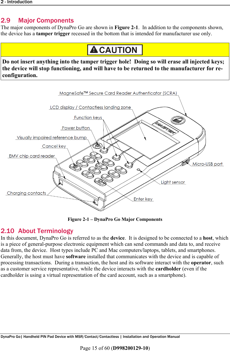
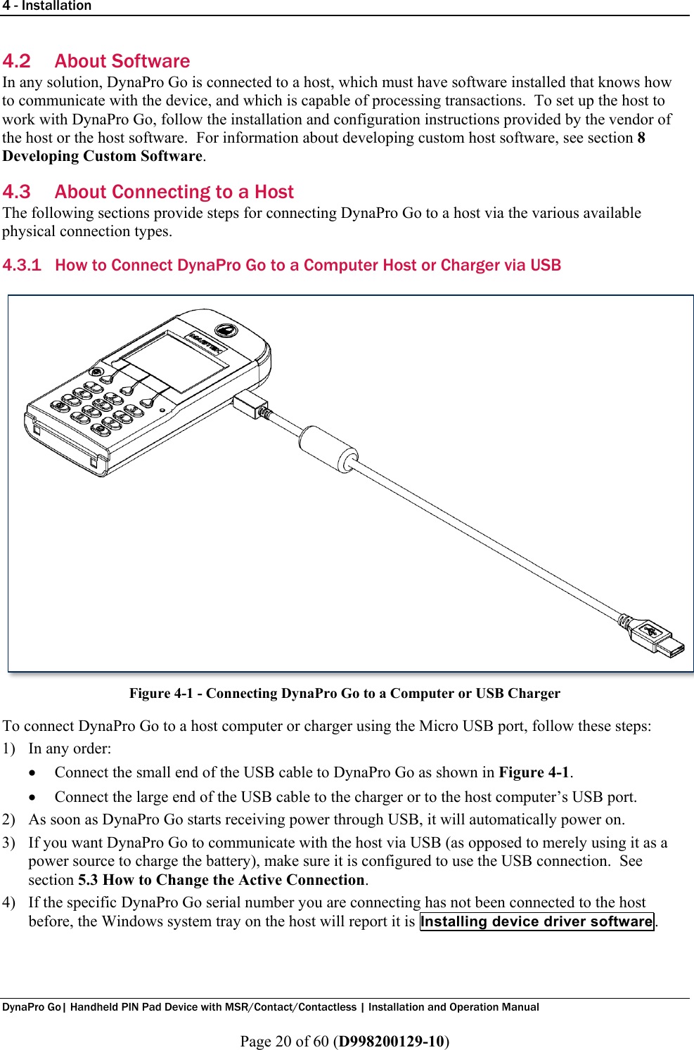
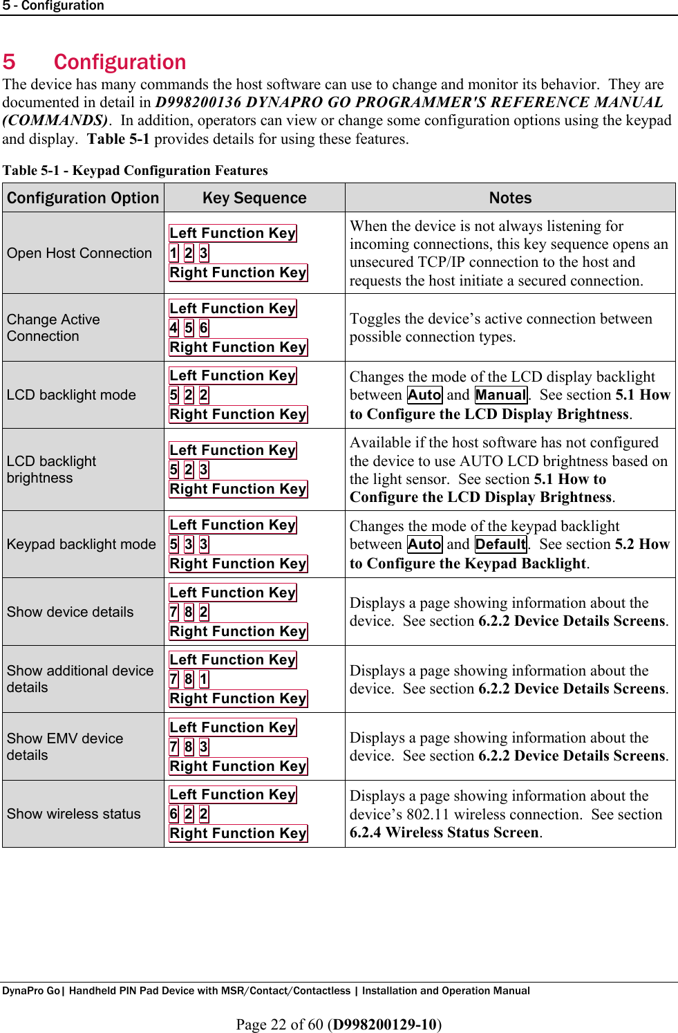
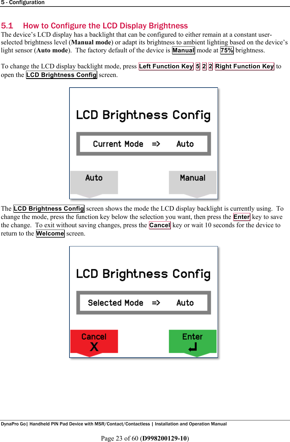
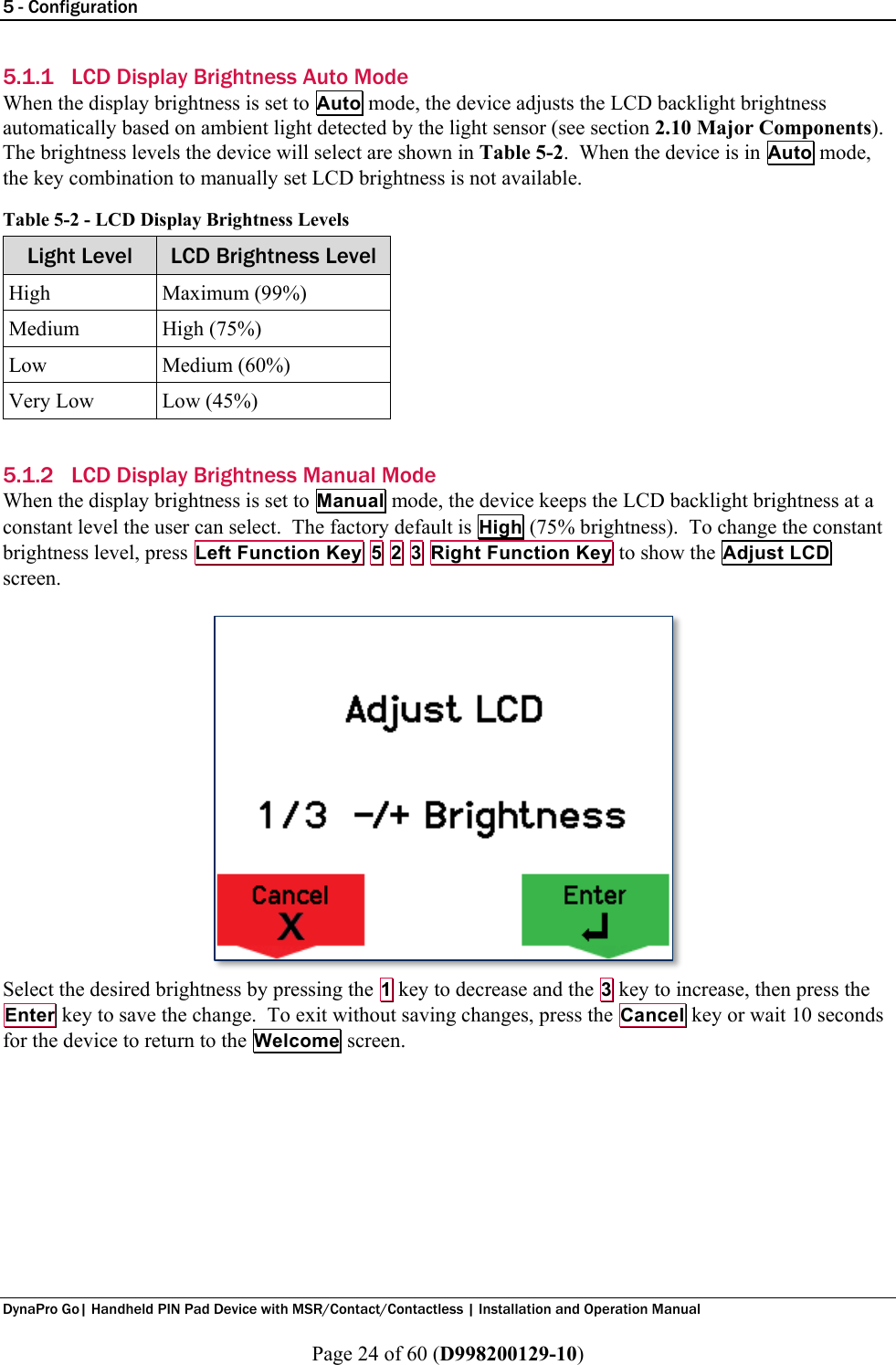
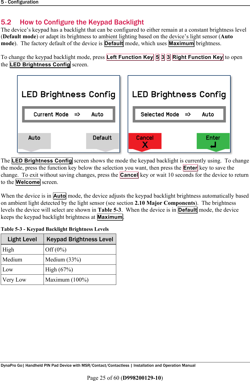
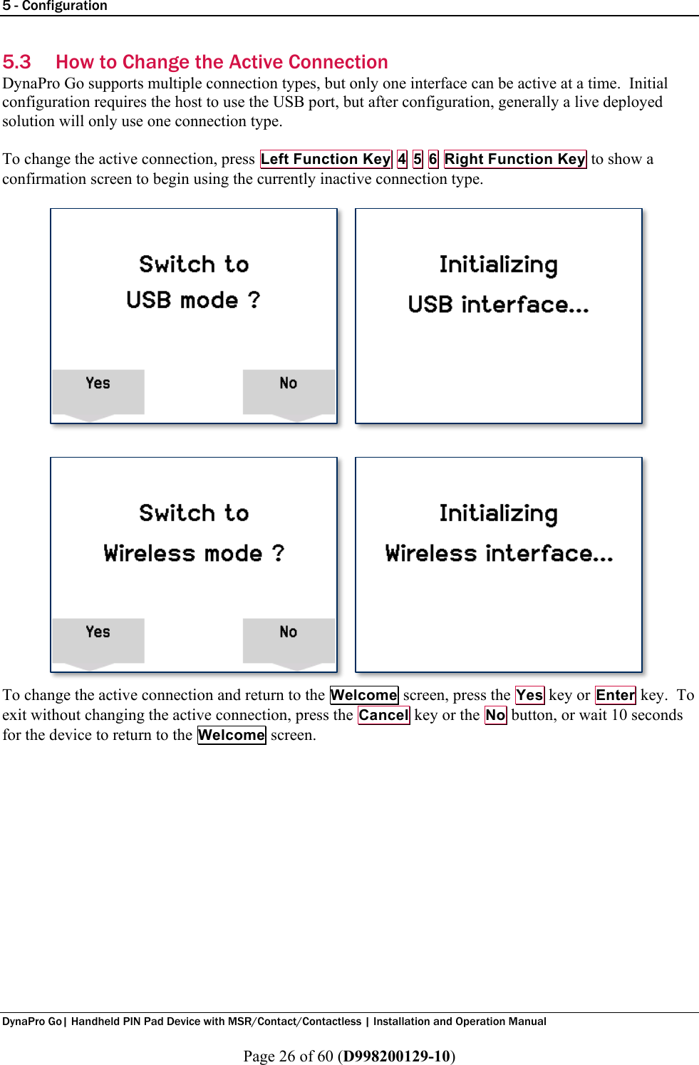
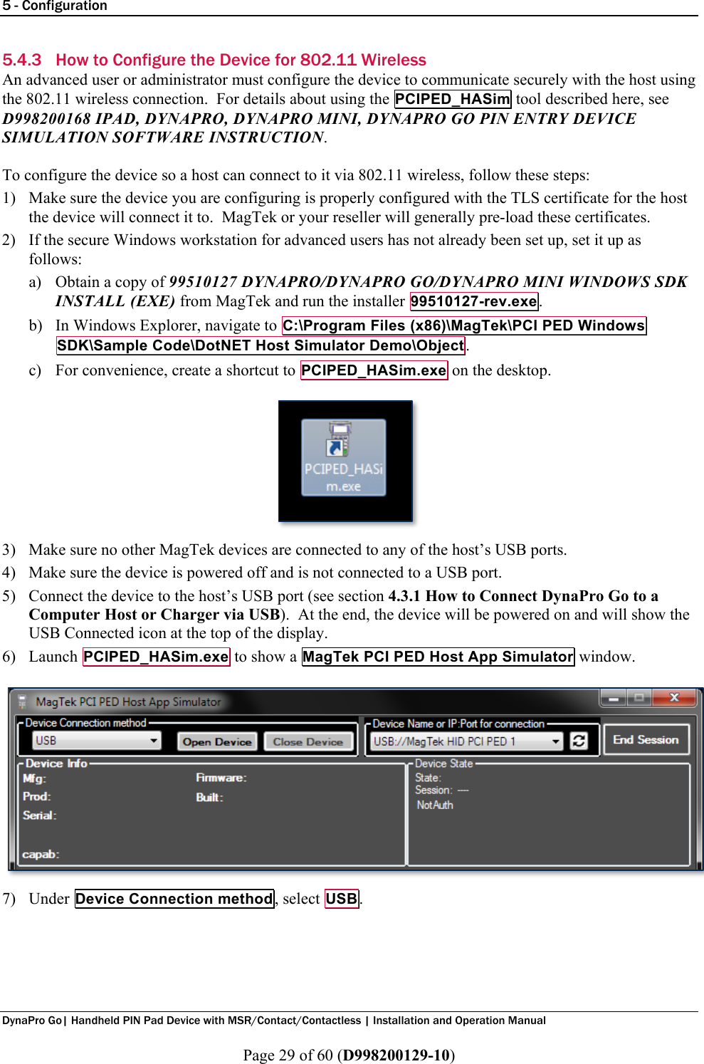
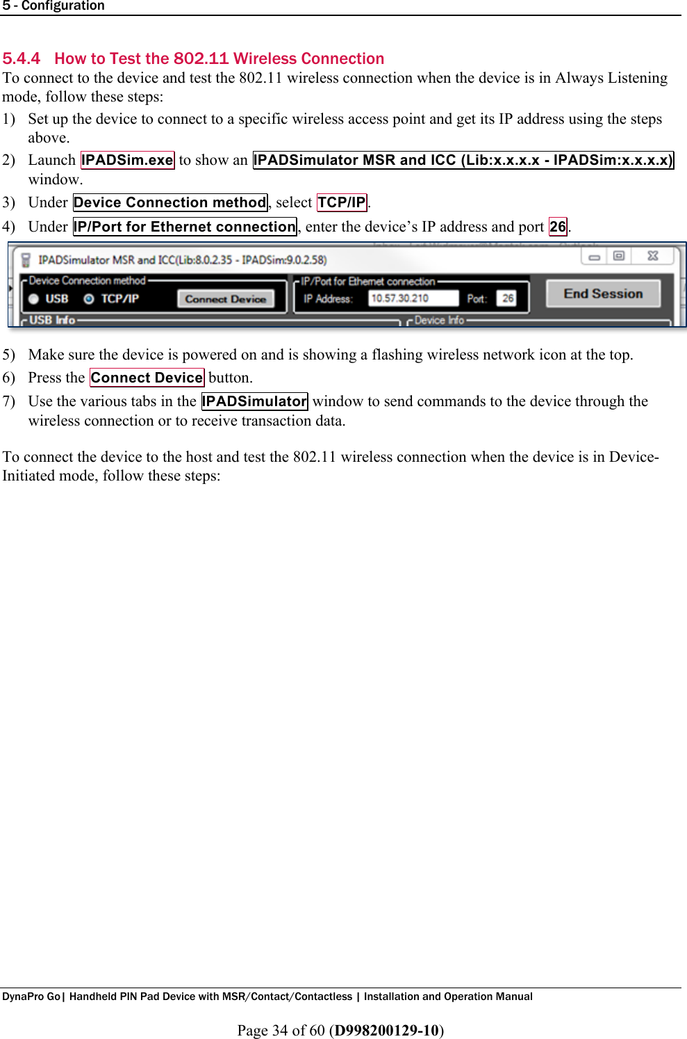
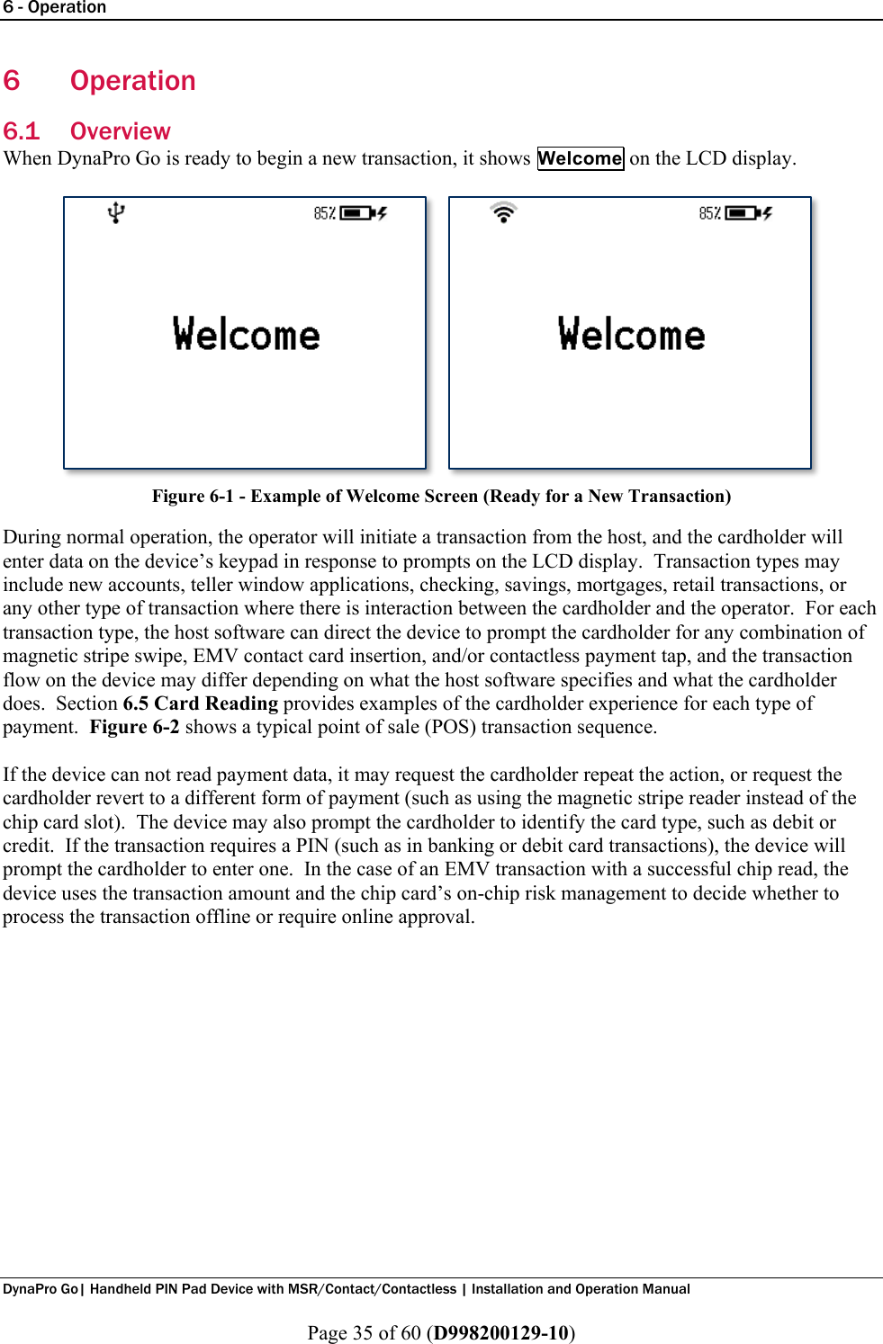
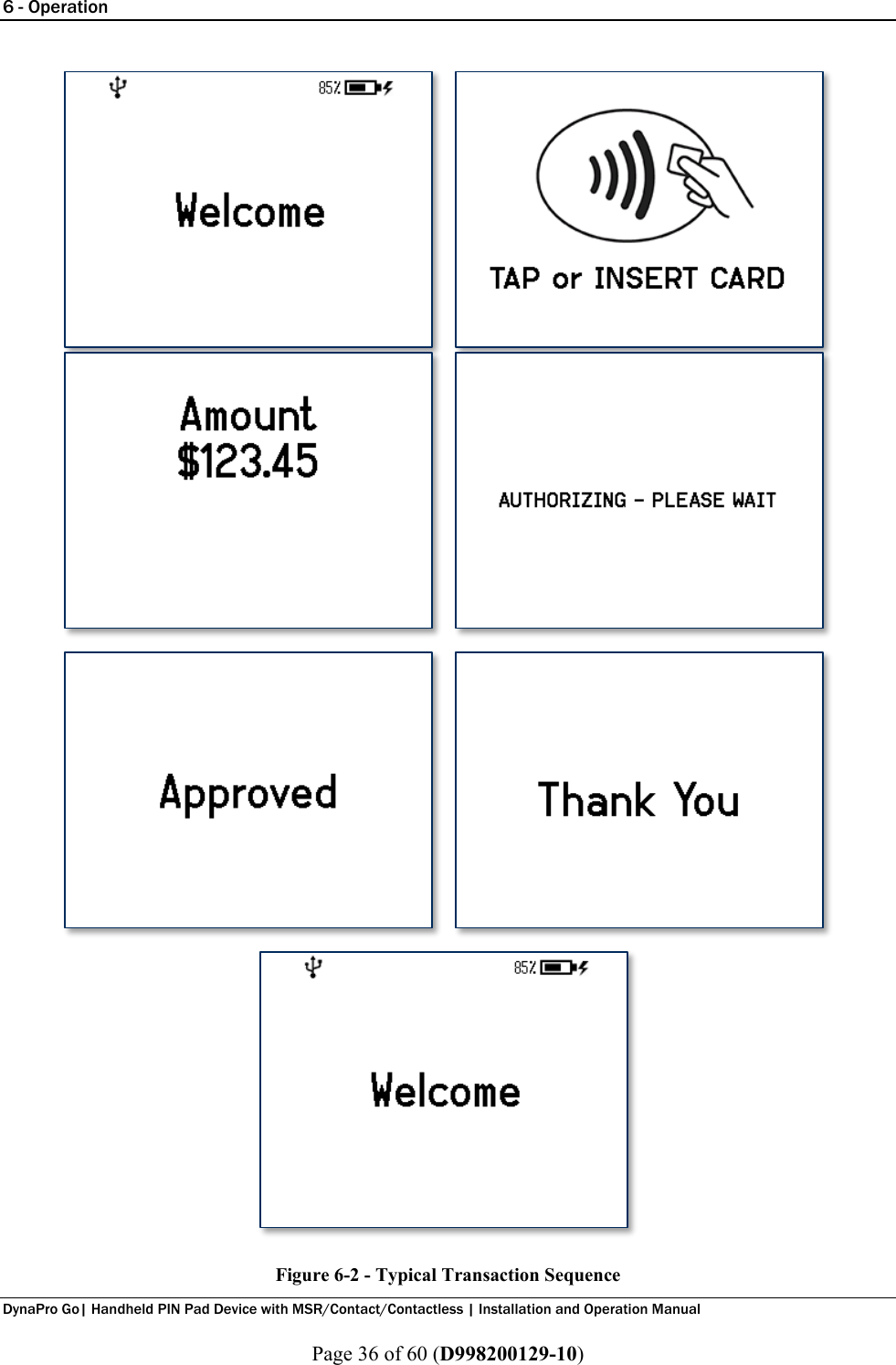
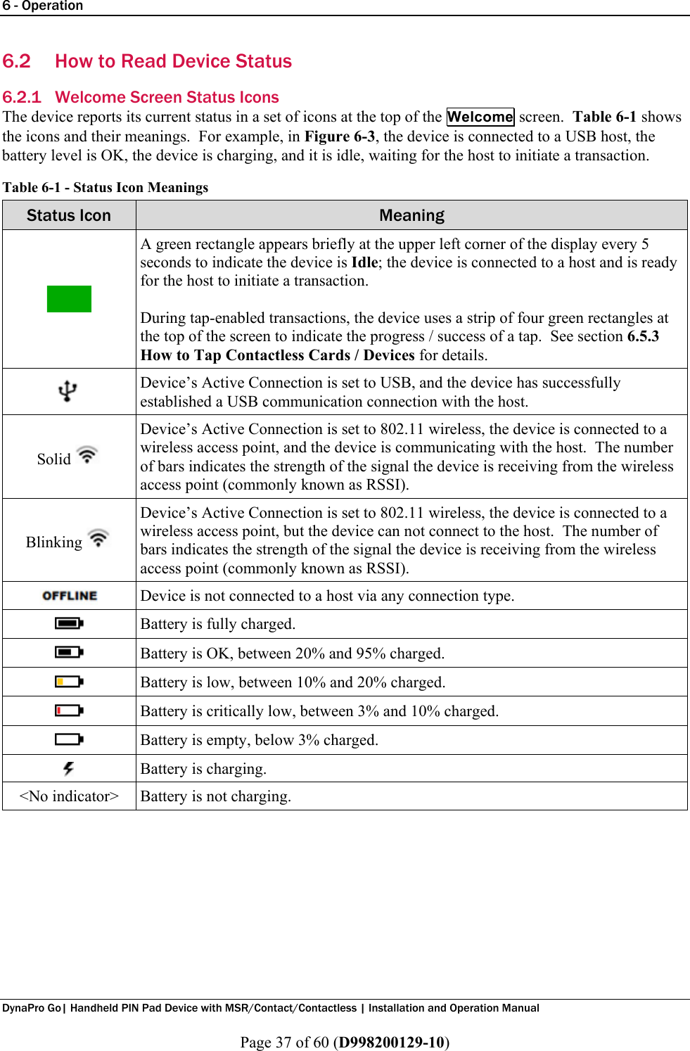
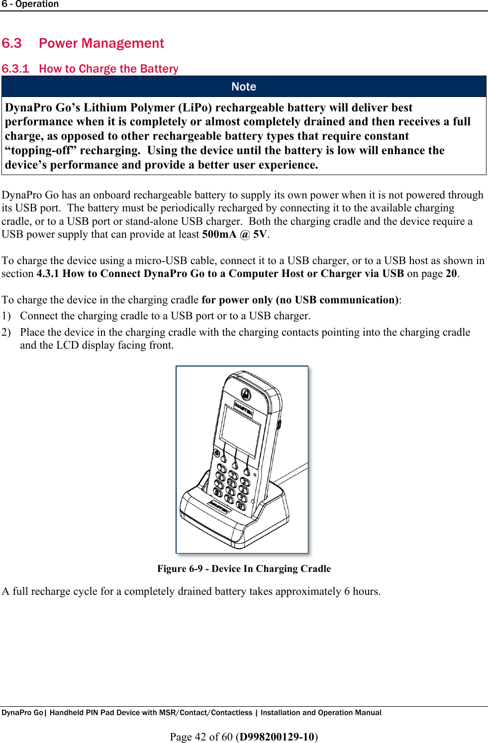
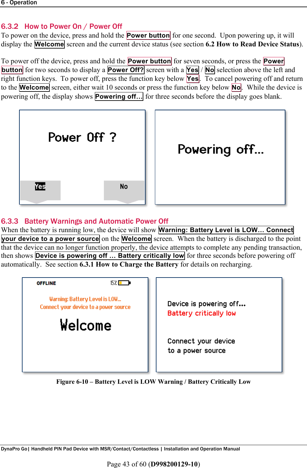
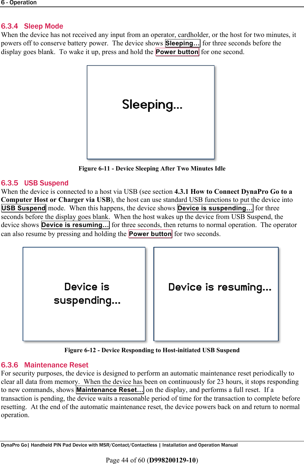
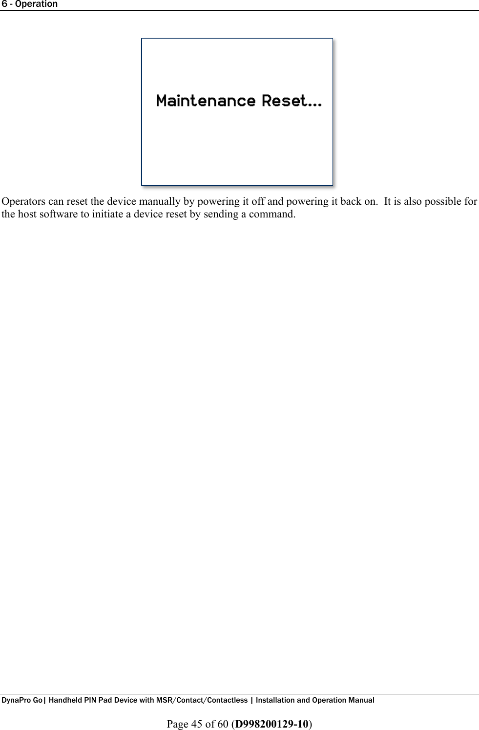
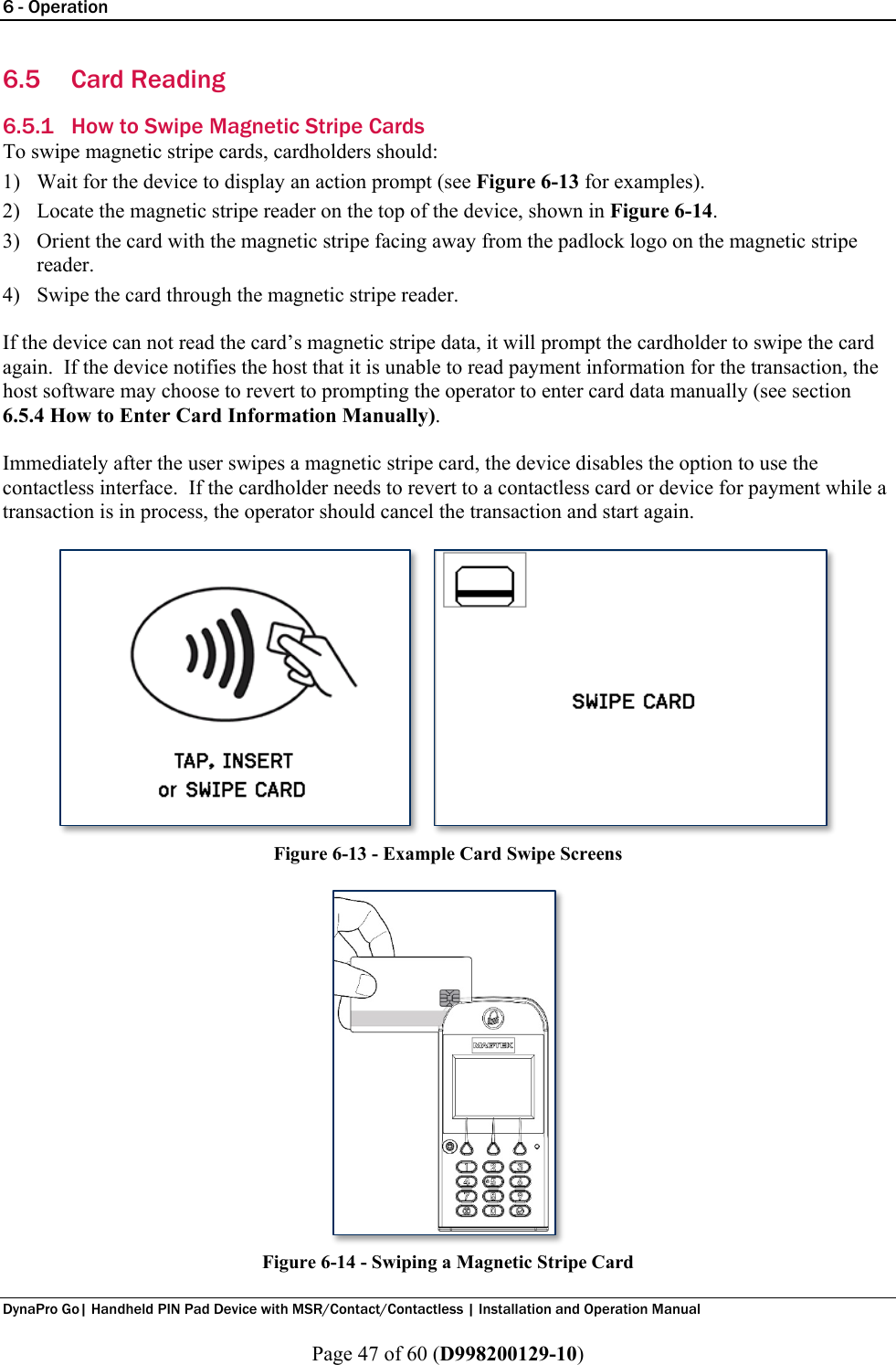
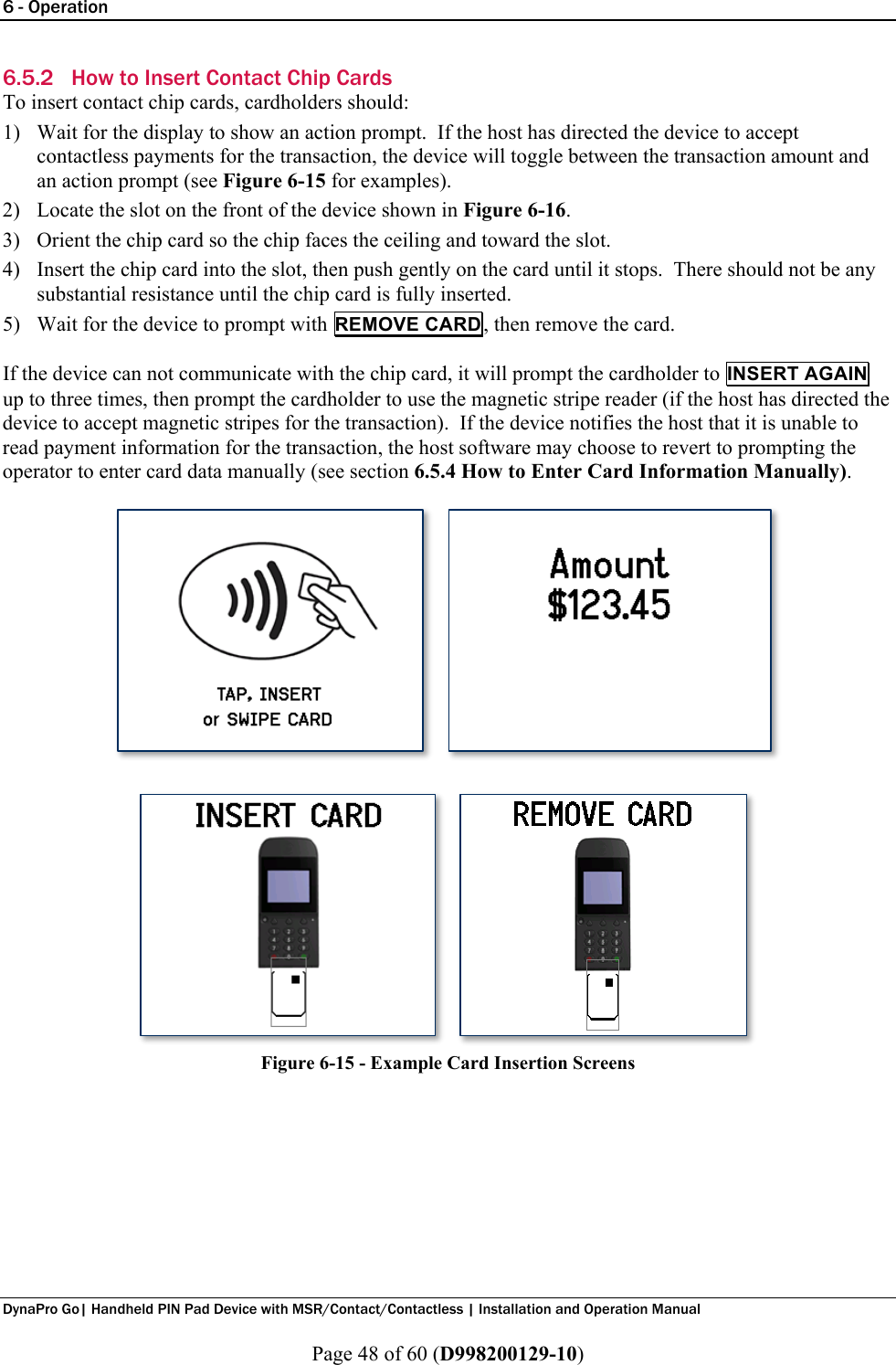
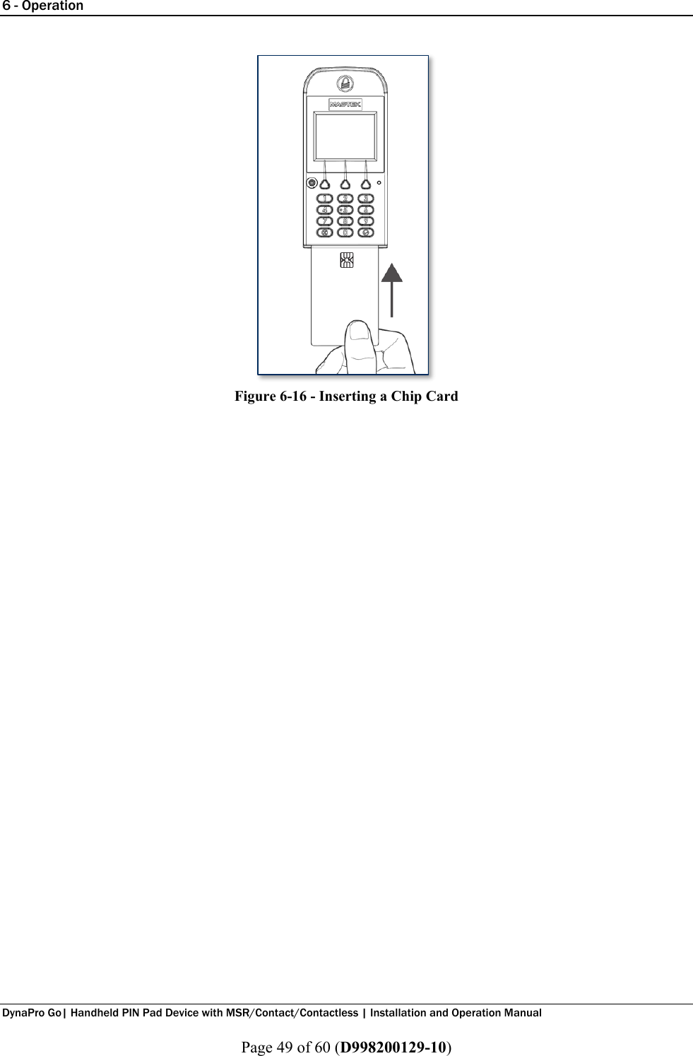
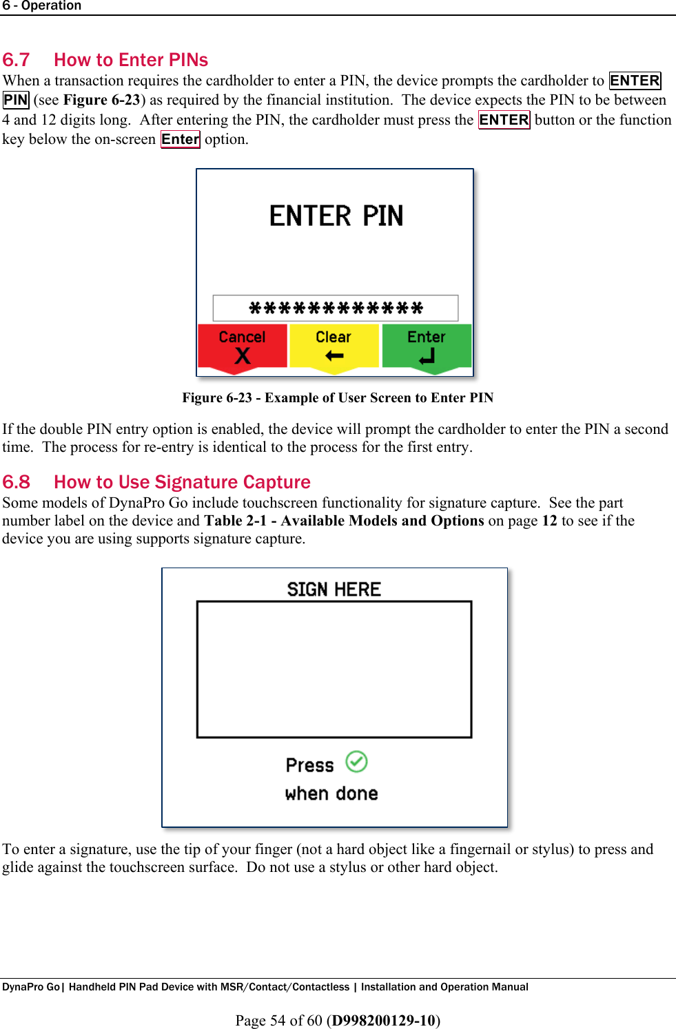
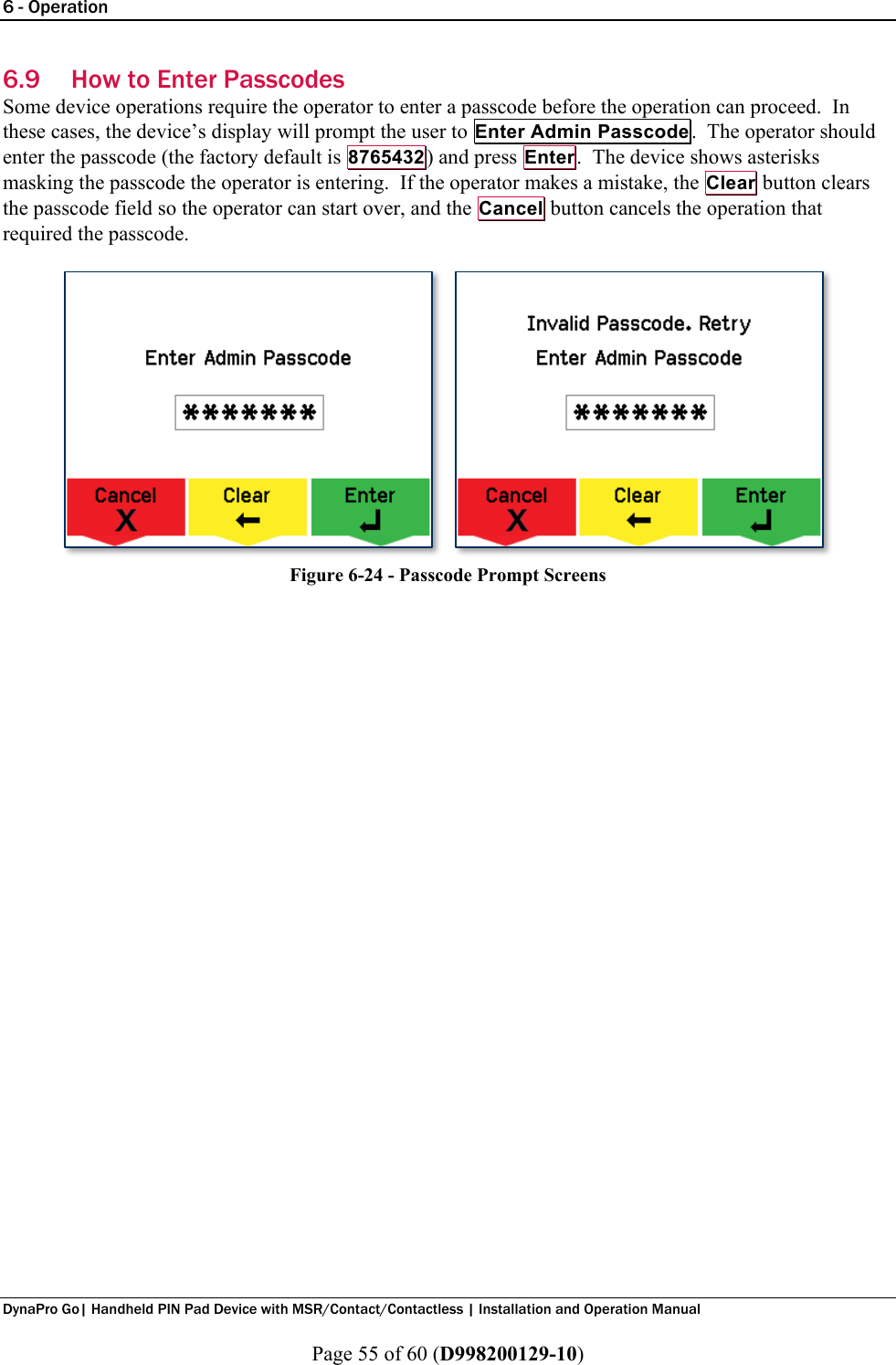
![4 - Installation DynaPro Go| Handheld PIN Pad Device with MSR/Contact/Contactless | Installation and Operation Manual Page 21 of 60 (D998200129-10) 5) When connecting to some hosts, Windows may show an error message reporting Device driver [software] was not successfully installed or Device unplugged. The error is harmless and the device may work immediately; if not, disconnect the device from the USB port, then re-connect it. 6) The device will show the USB Connected symbol at the top of the display (see section 6.2 How to Read Device Status). 4.3.2 How to Connect DynaPro Go to a Host via 802.11 Wireless To connect DynaPro Go to a host computer or charger using the 802.11 wireless connection, follow these steps: 1) Make sure the wireless access point, network, device, and host are set up properly and tested according to the steps in section 5.4 How to Configure Network Settings (ADVANCED). 2) Power on the device and make sure the device is configured to use the 802.11 wireless connection according to the steps in section 5.3 How to Change the Active Connection. 3) Make sure the device is connected to the wireless network by checking the status icons. For details, see section 6.2 How to Read Device Status.](https://usermanual.wiki/Magtek-orporated/30056216/User-Guide-3798294-Page-21.png)