Makita BUB360 BUB182 SC01 User Manual To The 89c73489 1265 4396 B31e 89a020621fec
User Manual: Makita BUB360 to the manual
Open the PDF directly: View PDF ![]() .
.
Page Count: 5
Models No.
Description
PRODUCT
CONCEPT AND MAIN APPLICATIONS
Specification
P 1/ 5
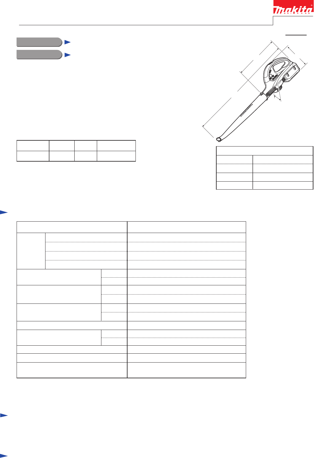
BUB360
Cordless Blower 36V
Model BUB360 is a cordless blower powered by 36V/ 2.6Ah
Li-ion battery BL3626. This model will be one of the best choice
for use especially in public spaces or among residential areas
instead of gas-powered blowers.
Features High/ Low push button for two different air volume settings.
This product is available with the following model number
and specifications.
Model No.
W
L1
H
BUB360
36
0.073 (4.4) [160]
0.043 (2.6) [92]
2.6
93
Li-ion
Voltage: V
Capacity: Ah
Cell
Battery
Max air volume*1:
m3/sec (m3/min.) [ft3/min.]
Max air velocity*2: m/sec
No
No
Vacuum function
Variable speed control by trigger
17,000
10,000
High
Low
High
Low
High
Low
No load speed: min-1 = rpm
Yes (2 settings: High/ Low)Air volume setting function
Continuous run time (approx.)
on a single full battery*1: min.
3.1 (6.8)
Weight according to
EPTA-Procedure 01/2003*4: kg (lbs)
Standard equipment
Optional accessories
Battery BL3626, Charger DC36RA, Battery adapter BAN36N
Note: The standard equipment for the tool shown above may differ by country.
Long nozzle .................. 1
22 with DC36RA
Charging time (approx.): min.
The model also includes the accessory listed below
in "Standard equipment".
BUB360Z No No
Model No. Charger
No
Battery coverBattery
*1 without Long nozzle
*2 with Long nozzle
*3 with Battery BL3626
*4 with Battery BL3626 and Long nozzle
L2
14
30
High
Low
57
Shoulder strap ............. 1
TECHNICAL INFORMATION
Dimensions: mm (")
Width (W)
Height (H)
Length (L1)
Length (L2)
142 (5-5/8)
921 (36-1/4)
436 (17-1/8)
204 (8)
*L1: Length with Long nozzle
*L2: Length with without Long nozzle
P 2/ 5
Repair
[1] NECESSARY REPAIRING TOOLS
[2] DISASSEMBLY/ASSEMBLY
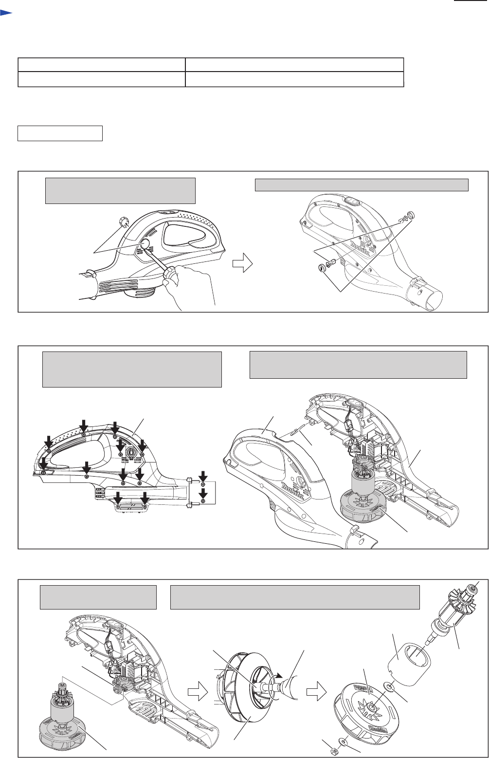
[2]-1. Fan, Armature
Description Use for
Remove two Holder cap covers by
levering up with Slotted screwdriver.
Remove 13pcs. of 4x18 Tapping screws.
And separate Housing set (R) from Housing
set (L).
Separate Motor section (Endbell complete, Armature,
Yoke unit, Fan 95) from Housing set (L).
Note: Do not lose Hanger
Remove two Brush holder caps and Carbon brushes.
Socket bit 8-55 (width across flats: 8mm) Disassembling/ Assembling M5-8 Hex nut for Fan 95
DISASSEMBLING
Holder cap cover
(2pcs.)
Carbon brush
(1) Remove Carbon Brush as illustrated in Fig. 1.
(2) Separate Housing set (R) and take out Motor section as illustrated in Fig. 2.
Brush holder cap (2pcs.)
Housing set (R)
Housing set (L)
Housing set (R)
Motor section
Fig. 1
Fig. 2
Hanger
CAUTION: Repair the machine in accordance with “Instruction manual” or “Safety instructions”.
1. Separate Motor section
from Endbell complete.
Fig. 3
(3) Fan 95 and Armature can be replaced as illustrated in Fig. 3.
2. Hold Fan 95 by hand and turn M5-8 Hex nut for Fan 95
clockwise using cordless impactdriver with Socket bit 8-55.
Note: M5-8 Hex nut has a left handed thread.
Fan 95
Fan 95
Socket bit 8-55 Cordless impactdriver
M5-8 Hex nut
Flat washer 5
Flat washer 8
Fan 95
Yoke unit
Armature
Endbell
complete
P 3/ 5
Repair
[2] DISASSEMBLY/ASSEMBLY
[2]-1. Fan, Armature (cont.)
Take the disassembling step in reverse.
Note: 1) Do not forget to set Flat washer 5 and Flat washer 8 in place. (Fig. 3)
2) Fit two notches of Yoke unit to two protrusions on Housing set (L). (Fig. 4)
3) Before assembling Housing set (R), mount Hanger on Housing set (L) and (R). (Fig. 2)
Fig. 4
ASSEMBLING
two notches
of Yoke unit
two protrusions of Housing set (L)
Fan 95
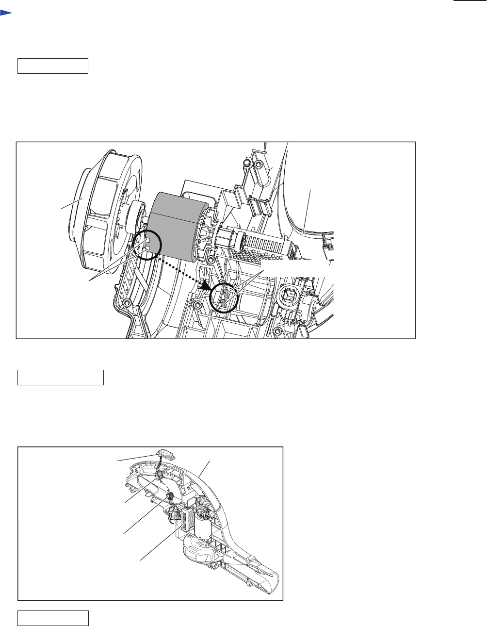
[2]-2. Switch unit
DISASSEMBLING
ASSEMBLING
Fig. 5
(1) Remove Housing set (R) from Housing set (L). (Figs. 1 and 2)
It is not necessary to remove Motor section.
(2) Remove Switch unit by disconnect Connectores as illustrated in Fig. 5.
Take the disassembling step in reverse.
Housing set (L)
Connector of Switch unit
Connector of Controller
Controller
Switch unit
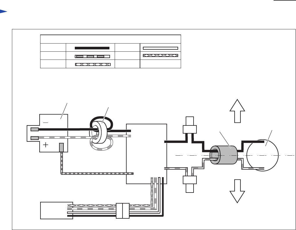
Circuit diagram
P 4/ 5
White
Blue
Yellow
Color index of lead wires' sheath
Black
Red
Line filter
Fig. D-1
Housing set (R) side
Housing set (L) side
Line filter
Connect Line filters as illustrated below if they are used.
Line filter
Switch
unit
Controller
Terminal
Endbell
complete
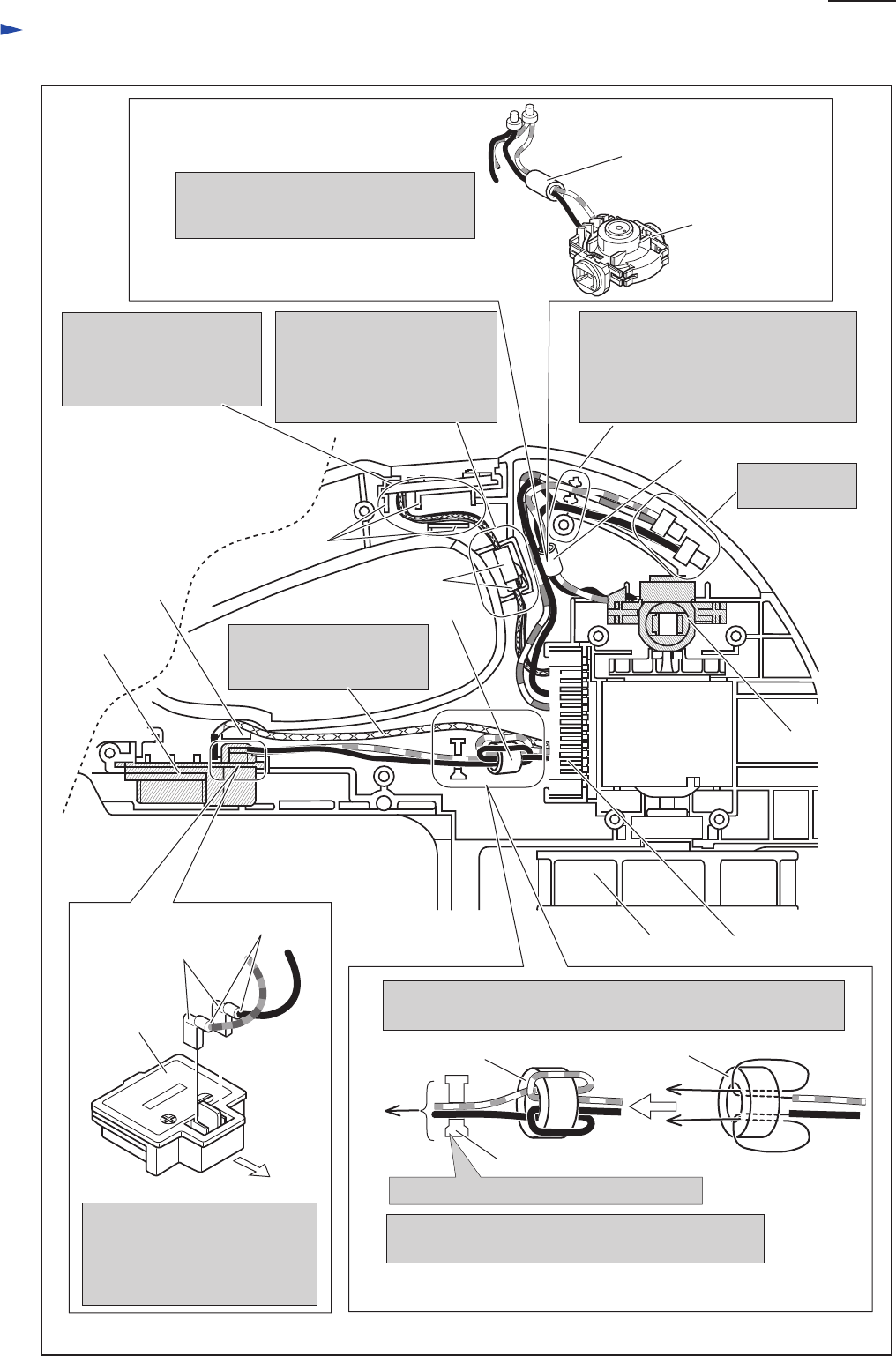
Wiring diagram in Housing set (L)
P 5/ 5
Guide Switch units’s Lead
wires between Ribs
carefully not to put them
on the Ribs.
Put Insulated
connectors here.
Fix the following Lead wires with
these Lead wire holders.
* Endbell’s Lead wires (black, red)
* Controller’s Lad wires (black, red)
Endbell
complete
Line filter
Line filter
Line Filter
Pass Line filter’s Lead wires (black, red)
through Line filter, and then put the Line
filter as illustrated below.
Connector
Put Connectors to the position
illustrated below, and fix
the Lead wires of Switch unit
and Controller with Lead wire
holders.
Do not pass Controller’s
lead wire (yellow) between
Rib and Terminal.
Line filter
Line filter
Passing Controller’s Lead wires (black, red) through Line filter,
coil them one time to Line filter as illustrated below.
Terminal
Rib
Rib
Fix the Lead wires with Lead wire holder.
to
Terminal
Fan 95 Controller
Yoke unit
Lead Wire Holder
In case of the specifications without Line filter,
no need to fix the lead wires with Lead wire holder.
The Flag connector has to be
connected so that its wire
connecting portion faces
Motor section side (front side).
Flag connector
Wire connecting portion
Terminal
Motor section side
Endbell Complete
Fig. D-2
