Mantis 7222E User Manual TILLER/CULTIVATOR Manuals And Guides L0705071
MANTIS Cultivator Manual L0705071 MANTIS Cultivator Owner's Manual, MANTIS Cultivator installation guides
User Manual: Mantis 7222E 7222E MANTIS TILLER/CULTIVATOR - Manuals and Guides View the owners manual for your MANTIS TILLER/CULTIVATOR #7222E. Home:Farm Equipment Parts:Mantis Parts:Mantis TILLER/CULTIVATOR Manual
Open the PDF directly: View PDF ![]() .
.
Page Count: 32

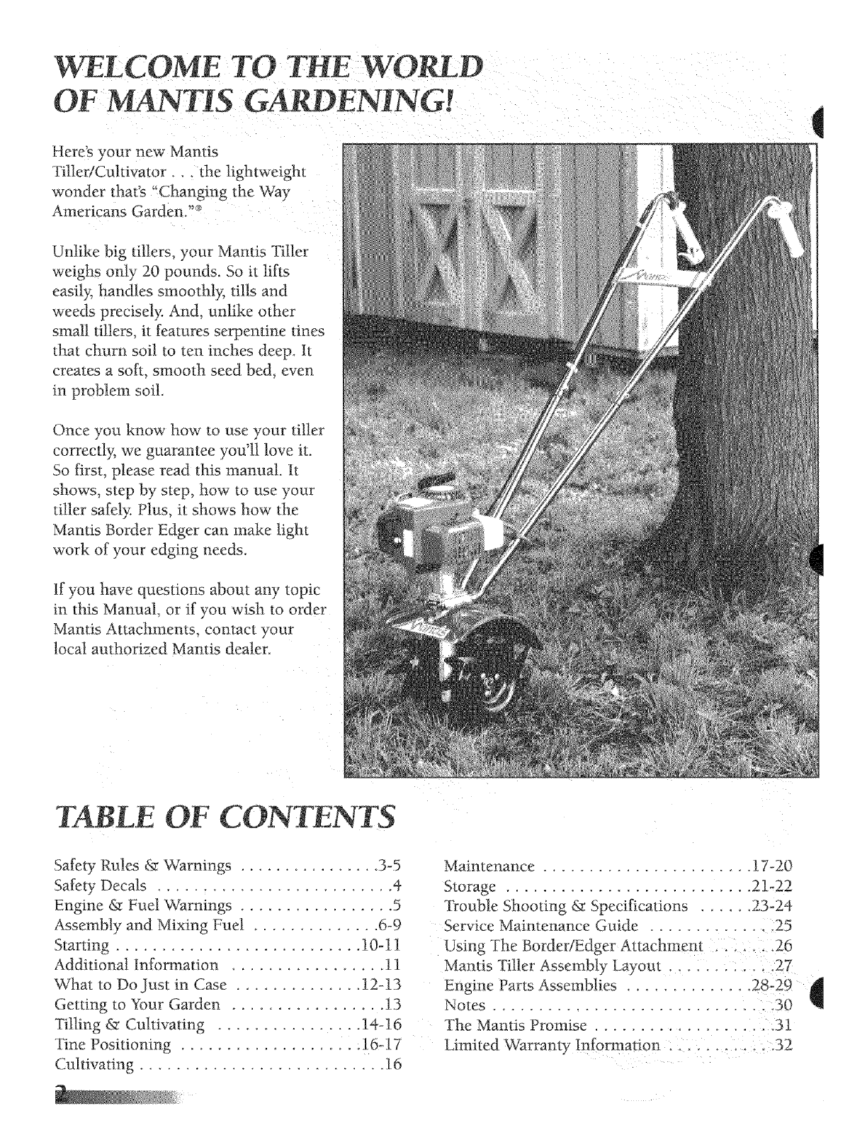
WELCOME TO THE WORLD
OF L4NTIS GARDENTNGr.
Here's your new Mantis
Titler/Cuhivator . the lightweight
wonder that's "Changing the Way
Americans Garden."_
Unlike big tillers, your Mantis Tiller
weighs only 20 pounds. So it lifts
easily, handles smoothly, fills and
weeds precisely. And, unlike other
small tillers, it features serpentine tines
that chum soil to ten inches deep. It
creates a soft, smooth seed bed, even
in problem soil.
Once you know how to use your tiller
correctl}; we guarantee you'll love it.
So first, please read this manual. It
shows, step by step, how to use your
tiller safely: Plus, it shows how the
ManOs Border Edger can make light
work of your edging needs.
if you have questions about any topic
in this Manual, or if you wish to order
Mantis Attachments, contact your
local authorized Mantis dealer.
q
TABLE OF CONTENTS
Safety Rules & Warnings ................ 3-5
Safety Decals .......................... 4
Engine & Fuel Warnings ................. 5
Assembly and Mixing Fuel .............. 6-9
Starting ........................... 10-11
Additional InformaOon ................. 11
What to Do Just in Case .............. 12-13
Getting to Your Garden ................. 1.3
Tilling & Cultivating ................ 14-16
Tine Positioning .................. :16-17
CulOvating ........................... 16
Maintenance ....................... 17-20
Storage ........................... 21-22
Trouble Shooting & Specifications ...... 23_24
Service Maintenance Guide ............ 2 ;25
Using The Border/Edger Attachment . . 26
Mantis Tiller Assembly Layout ...... : , ;_27
Engine Parts Assemblies .............. 28_29 4
Notes ............................ .30
The Mantis Promise ................... 31
Limited _Varranty Information . .......... 32
SAFE_ RULES & WARNINGS
ou will notice throughout this Owners Manual Safety Rules and Important Notes, Make sure you
derstand and obey these warnings for your own protection.
I. Special Safety Information
II. Safety & Warnings
&WARNING: TheEogineExhaust from this product contains chemicals known
to the State of California to cause cancer, birth defects or other reproductive harm,
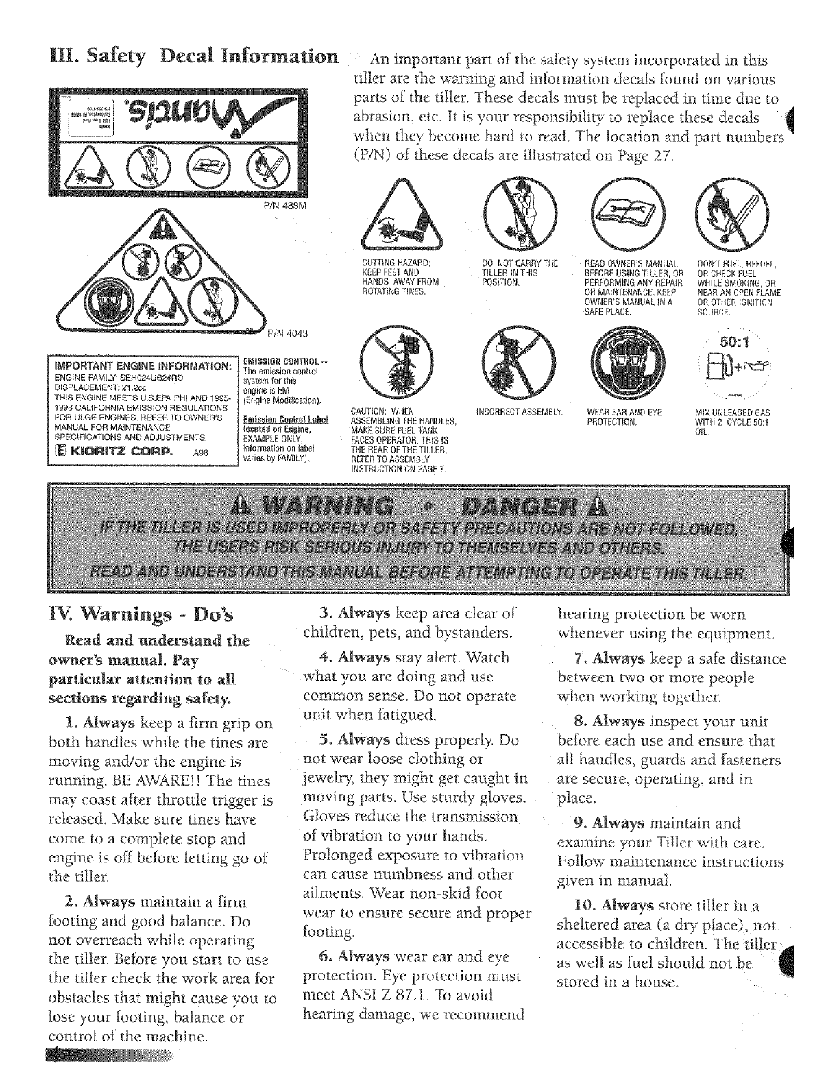
Decal Information An important part of _:hesafety system incorporated in this
tiller are the warning and information decals found on various
parr of the tiller. These decals must be replaced in time due to
abrasion, etc. It is your responsibility to replace these decals d
when they become hard to read. The location and part numbers v!
(P/N) of these decals are illustrated on Page 27.
P/N 488M
IMPORTANT ENGINE INFORMATION:
ENGINE FAMILY: SEHO24UB24RD
DISPLACEMENT: 21,2cc
THIS ENGINE MEETS U,S,EPA PHi AND 1995-
1998 CALIFORNIA EMISSION REGULATIONS
FOR ULGE ENGINE& REFER TO OWNER'S
MANUAL FOR MAINTENANOE
SPECIFICATIONS AND ADJUSTMENTS,
KJORllTZ CORP. A98
ENIgGIONCONTROL-_
Theemission control
sys_emfor this
engine is EM
(Engine Modification).
CUTJtNGHAZARD; DO NOTCARRYTHE READOWNER'SMANUAl. DON'TFUEL REFUEL,
KEEPFEETAND TILLERINTHiS BEFOREUSINGTILLER, OR OR CHECKFNEt
HANDS AWAYFROM POSITION PERFORMINGANYREPAIR WNILESMOKING,OR
ROTATINGTINES. DR MAINTENANCEKEEP NEARANOPENFLAME
OWNER'SMANUAL tN A OR OTHERiGNiTiON
SAFEPLACE. SOURCE.
CAUTION: WHEN
ASSEMBLINGTHEHANDLES,
Io_ateg on E_gine, MAKESUREFUELL_,NK
EXAMPLEONLY, FACESOPERATOR.[HIS iS
information on label THE REAROFTHETILLER,
varies by FAMILY) REFERTOASSEMBLY
INSTRUCTIONON PAGE7.
INCORRECTASSEMBLY• WEAR EARAND EYE
PROTECTION,
50:t
MIX UNLEADEDGAS
WITH 2 CYCLE50:1
OIL,
IV. Warnings - Do's
Read and understand the
owner's manual. Pay
particular attention to all
sections regarding safety.
1. Always keep a firm grip on
both handles while the tines are
moving ancgior the engine is
running. BE AWARE!! The tines
may coast after throttle trigger is
released. Make sure tines have
come to a complete stop and
engine is off before letting go of
the tiller.
2_ Always maintain a firm
footing and good balance. Do
not overreach while operating
the tiller. Before you start to use
the tiller check the work area _Br
obstacles that might cause you to
lose your footing, balance or
control of the machine.
3. Always keep area clear of
children, pets, and bystanders
4. Always stay alert. Watch
what you are doing and use
common sense. Do not operate
unit when fatigued.
5o Always dress properly. Do
not wear loose clothing or
jewelry, they roight get caught in
moving parts. Use sturdy gloves.
Gloves reduce the transmission
of vibration to your hands.
Prolonged exposure to vibration
can cause numbness and other
ailments. Wear non-skid foot
wear to ensure secure and proper
footing.
6. Always wear ear and eye
protection. Eye protection must
meet ANSI Z 87A. To avoid
hearing damage, we recommend
hearing protection be worn
whenever using the equipment.
7. Always keep a safe distance
between two or more people
when working together.
8_ Always inspect your unit
before each use and ensure that
all handles, guards and fasteners
are secure, operating, and in
place.
9° Always maintain and
examine your Tiller with care.
Follow maintenance instructions
given in manual.
10. Always store titler in a
sheltered area (a dry place), not
accessible tofhildren. The tilter d
as well as Nel should not he
stored in a house.
_,_ W_rnings ° Don*ts
Don't use tiller with one hand
eep both hands on handles with
_'ingers and tlmmbs encircling
the handles, while tines are
moving, and engine is running.
Don't overreach. Keep a good
Don't attempt to clear tines
while they are moving Never try
to remove jammed :material
before switching the engine off
and making sure the Ones have
stopped completely.
Don't allow children or
incapable people to operate this
tiller.
Don't operate while under
the influence of alcohol or drugs.
Don't attempt to repair this
tiller, Have repairs made by a
qualified dealer or repairman.
See that only original Mantis
parts are used.
Engine/Fuel Warnings
Always use flesh gasoline in
the fuel mixture. Stale gasoline
Dan Cause damage.
Always pull starter cord
slowly until resistance is felt.
Then pull cord rapidly to avoid
kickback and prevent arm or
-Do's
Always operate engine with
spark arrestor installed and
operating properl> The use of
spark arrestor muftters is
required by law in the state of
California (Section 4442 of the
California Public Resources
Code), as wei1 as in other states
or municipalities. Federal taws
apply on federal lands.
_Io Engine/Fuel Warnings - Don'ts
Don't flue!, retiael or check fuel
while smoking, or near an open
flame or other ignition source.
Stop engine and be sure it is cool
Don't leave the engine running
while the tiller is unattende& Stop
engine before putting the tiller
down or while transporting f?om
one place to another.
_Don't refuel, start or run this
ller indoors or in an improperly
ventilated area
Don't run engine when
electrical system causes spark
outside tbe @inder. During
periodical checks of the spark
plug, keep plug a sate distance
from cylinder to avoid burning of
evaporated fuel from cylinder.
Don't check for spark with
spark ping or plug wire removed,
Use an approved tester.
Don't crank engine with spark
plug removed unless spark plug
wire is disconnected. Sparks can
ignite fumes.
Don't run engine when the
odor of gasoline is present or
other explosive conditions exisL
Don't operate the uni_ if
gasoline is spilled. Clean up spill
completely before starting engine.
Don't _pera_e your tiller if
there is an accumulation of debris
around the muffler_ and cooling
flus.
Don't touch hot mufflers.
cylinders or cooling [_ns as
comact may cause sermns burns.
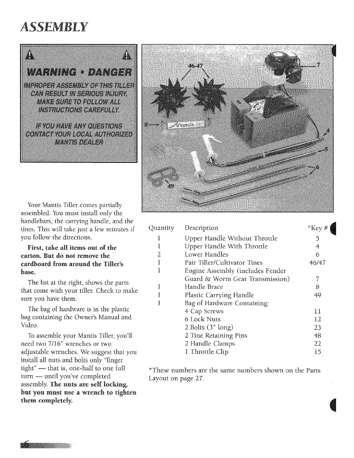
ASSEMBLY
Your Mantis Tiller comes partially
assembled. You must install only the
handlebars, the carrying handle, and the
tines. This will take just a few minutes if
you tbltow the directions.
First, take all items out of the
carton. But do not remove the
cardboard from around the Tiller's
base.
The list at the right, shows the parts
that come with your tiller. Check to make
sure you have them.
The bag of hardware is in the plastic
bag containing the Owner's Manual and
Video.
To assemble your Mantis "Filler, you'll
need two 7116" wrenches or two
adjustable wrenches. We suggest that you
install all nuts and bolts only "finger
fight" -- that is, one-half to one full
turn- until you've completed
assembly. The nuts are self locking,
but yon must use a wrench to tighten
them completely.
Quantity
1
1
2
1
1
1
1
1
Description *Key #
Upper Handle Without Throttle 5
Upper Handle With Throttle 4
Lower HanOes 6
Pair Tiller!Cuhivator Tines 46/47
Engine Assembly (includes Fender
Guard & Vv_rm Gear Transmission) 7
Handle Brace 8
Plastic Carrying Handle 49
Bag of Hardware Containing:
4 Cap Screws t 1
6 Lock Nuts 12
2 Bolts (3" tong) 23
2 Tine Retaining Pins 48
2 Handle Clamps 22
1 Throttle Clip i5
*These numbers are the same numbers shown on the Parts
Layout on page 27.
q
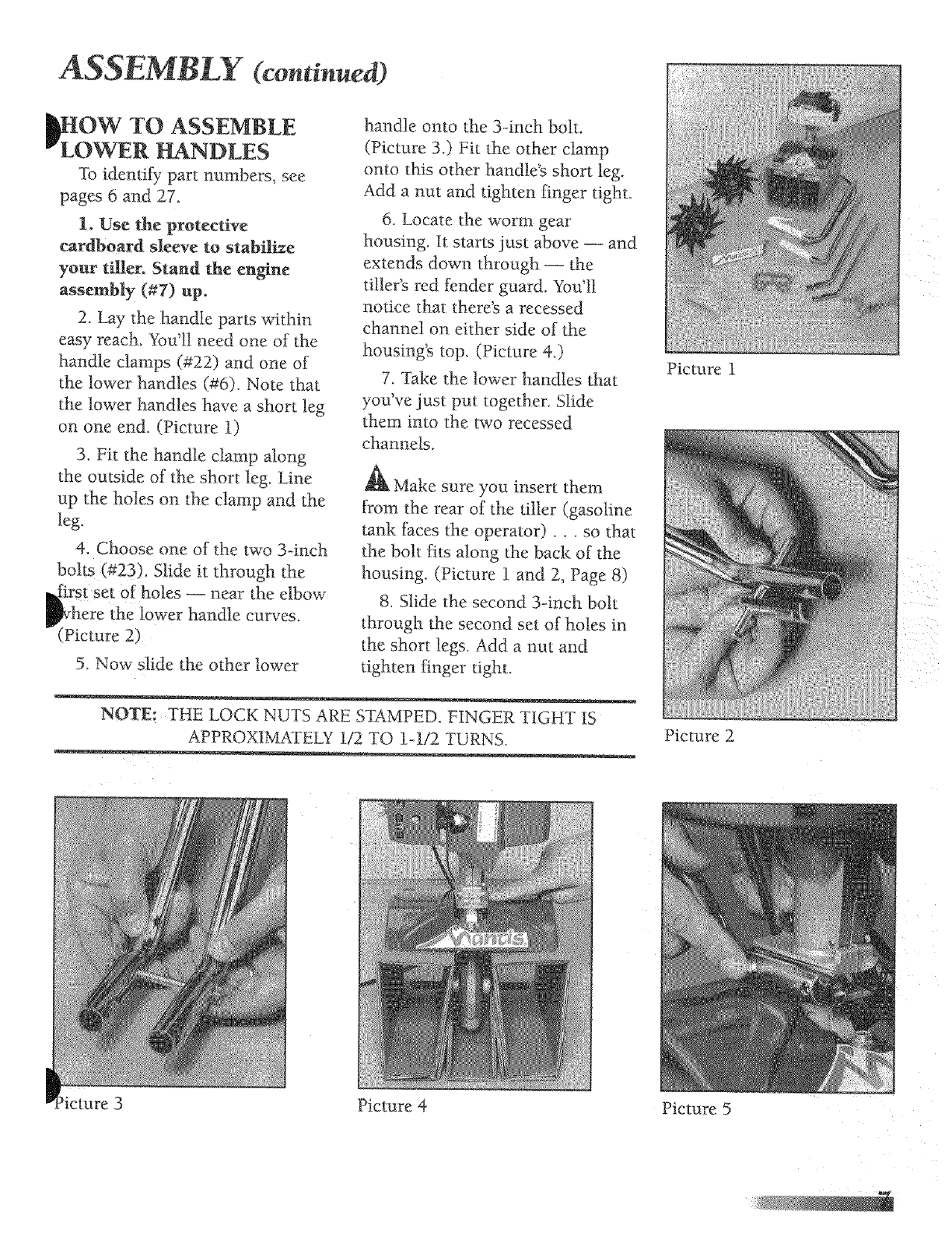
ASSEMBLY (continued)
_OW TO ASSEMBLE
LOWER HANDLES
I_9 idemify part numbers, see.
pages 6and 27.
1. Use the protective
cardboard sleeve to stabilize
your tiller. Stand the engine
assembly (#7) up,
2. Lay the handle parts within
easy reach. You'll need one of the
hanNe clamps (#22) and one of
the lower handles (#6). Note that
the lower handles have a short leg
on one end. (Picture 1)
3. Fit the handle ctamp along
the outside of the short leg. Line
up the holes on the clamp and the
leg.
4. Choose one of the two 3-inch
bolts (#23), Slide it through the
rstl se t of holes -- near the elbow
here the lower handle curves.
(Picture 2)
5. Now Slide the other lower
handle onto the 3-inch bolt.
(Picture 3.) Fit the other clamp
onto this other handteg short leg.
Add a nut and tighten finger tight.
6. Locate the worm gear
housing. It starts just above -- and
extends down through- the
tiller's red fender guard. You'll
notice that there's a recessed
channel on either side of the
housing's top. (Picture 4.)
7. Take the lower handles that
you've just put together. Slide
them into the two recessed
channels.
Make sure you insert them
from the rear of the tiller (gasoline
tank faces the operator).., so that
the bolt fits along the back of the
housing (Picture 1 and 2, Page 8)
8. Slide the second 3-inch bolt
through the second set of holes in
the short legs. Add a nut and
_ighten finger tight.
NOTE: THE LOCK NUTS ARE STAMPED. FINGER TIGHT IS
APPROXIMKFELY 112 TO 1-t/2 TURNS.
Picture 1
Picture 2
Picture 4 Picture 5
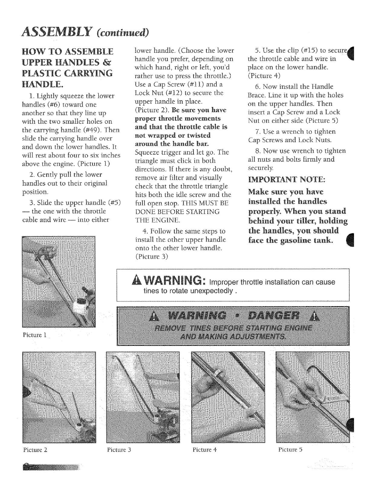
ASSEMBLY ¢continue )
HOW TO ASSEMBLE
UPPER HANDLES &
P_STIC CARR_IN G
HANDLE.
1. Lightly squeeze the lower
handles (#6) toward one
another so that they line up
with the two smaller holes on
the carrying handle (#49) Then
slide the carrying handle over
and down the lower handles. It
will rest about _mr to six inches
above the engine. (Picture 1)
2. Gently pull the lower
handles out to their original
position.
3. Slide the upper handle (#5)
the one with tile throtde
cable and wire _ into either
Picture 1
lower handle. (Choose the lower
handle you prefer, depending on
which hand, right or left, you'd
rather use to press the throttle.)
Use a Cap Screw (#11) and a
Lock Nut (#12) to secure the
upper handle in place.
(Picture 2). Be sure you have
proper throttle movements
and _hat, the throtde cable is
not wrapped or twisted
around the handle bar.
Squeeze trigger and let go. The
triangle must click in both
directions. If there is aW doubt,
remove air filter and visually
check that the throttle triangle
hits both the idle screw and the
gull open stop. THIS MUST BE
DONE BEFORE STAR-HNG
THE ENGtNE.
4. Follow the same steps to
install the other upper handle
onto the other lower handle.
(Picture 3)
5. Use the clip (#15) to secure_
the throttle cable and wire in I
place on the lower handle.
(Picture 4)
6. Now install the Handle
Brace. Line it up with the holes
on the upper handles. Then
insert a Cap Screw and a Lock
Nut on either side (Picture 5)
7. Use a wrench to 0ghten
Cap Screws and Lock Nuts.
8. Now use wrench to tighten
all nuts and bolts firmly and
securely.
IMPORTANT NOTE:
Make sure you have
installed the handles
properly. When you stand
behind your tiller, hMding
the handles, you should
face the gasoline tank.
WANNING: Improper throttle irlstaHation carl cause
tines to rotate unexpectedly °
Picture 2 Picture 3 Picture 4 Picture 5
ASSEMBLY €continued)
_ssembling the Tines
for Tilling
1. Remove the _:ardboard
trom around your Tiller_ base.
2. Slide the tines omo the
axle shafts. The "D" hole goes
on the outside.
3. Make sure you've installed
the tines properly [br tilling.
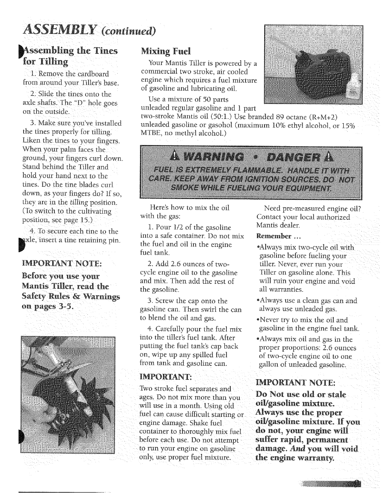
Mixing Fuel
Your Mantis Tiller is powered by a
commercial two stroke, air cooled
engine which requires a [:uel mixture
of gasoline and lubricating oil.
Use a mixm_v of 50 parts
unleaded regular gasoline and 1 part
two-stroke Mantis oil (50:1.) Use branded 89 octane (R+M+2)
unleaded gasoline or gasohol (maximum 10% ethyl alcohol, or 15%
MTBE no methyl alcohol.)
When your palm laces the
ground, your fingers curt down.
Stand behind the Tiller and
hold your hand next to the
tines_ Do the fine blades cuff
down. as your fingers do? If so,
they are in ihe ti_ling position.
(To switch to the cultivating
poNtion, see page 15. )
4. "Ib secure each tine to the
xle, insert atine retaining pin.
iMPORTANT NOTE:
Mantis Tiller, read the
on pages 3-5.
Here's how to mix the oil
with the gas:
l. Pour 1/2 of the gasoline
into a safe container_ Do not mix
the fuel and oil in the engine
[uel tank.
2. Add 2.6 ounces of two-
cycle engine oil to the gasoline
and mix Then add the rest of
the gasoline_
3 Screw the cap onto the
gasoline can. Then swirl the can
to blend the oil and gas.
4. Carefully pour the [iael mix
into the _iller's tuel tank After
putting the fuel tank's cap back
on. wipe up any spilled fuel
from tank and gasoline can.
Need pre-measured engine oil?
Contact your local authorized
Mantis dealer.
Remember ,.,
*Always mix lwo-cycle oil with
gasoline before fueling your
tiller. Never. ever run your
Tiller ot] gasoline alone. This
will rum your engine and void
all warranties.
*Always use a clean gas can and
always use unleaded gas.
*Never try 1o mix the oil and
gasoline m the engine fuel tank.
,Always mix oil and gas in the
proper proportions: 2.6 ounces
of two-cycle engine oil to one
gallon of _.mleaded gasoline.
iMPORTANT:
Two stroke fuel separates and
ages. Do not mix more than you
wilt use in a month. Using old
fuel can cause difficult starting or
IMPORTANT NOTE:
Do Not use old or stale
oi]igasnline mixture°
Always use the proper
engine damage. Shake fuel oil/gasoline mixture. I[ yon
container to thoroughly mix fuel do not, your engine will
before each use. Do not attempl snffer rapid, permanent
to run your engine on gasoline damage. And you wilt vni d
only, use proper fuel nnxtnie. [he engine warranty.
STARTING
To Start Tiller for
the First Time:
.1. Fill the fuel tank with the
proper oiUgasoline mixture.
(See preVious section.)
2. Hand tighten the gasoline
cap just until it's snug.
3. Place the start/stop switch
into the "start" position.
(Picture 1)
During cold starting, you may
need to pull at least three or
four times before the engine
fires.
NOTE: When the choke is
closed, never pull the cord more
than tbur or five dines.
Overpulling :may cause flooding.
Also, bear in mind that, when
the engine fires, it only coughs
or sputters, and wi!l not run
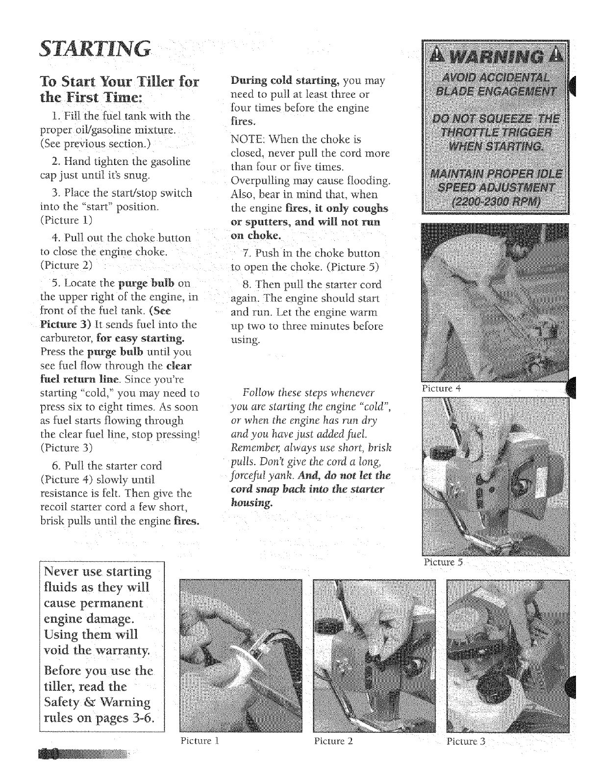
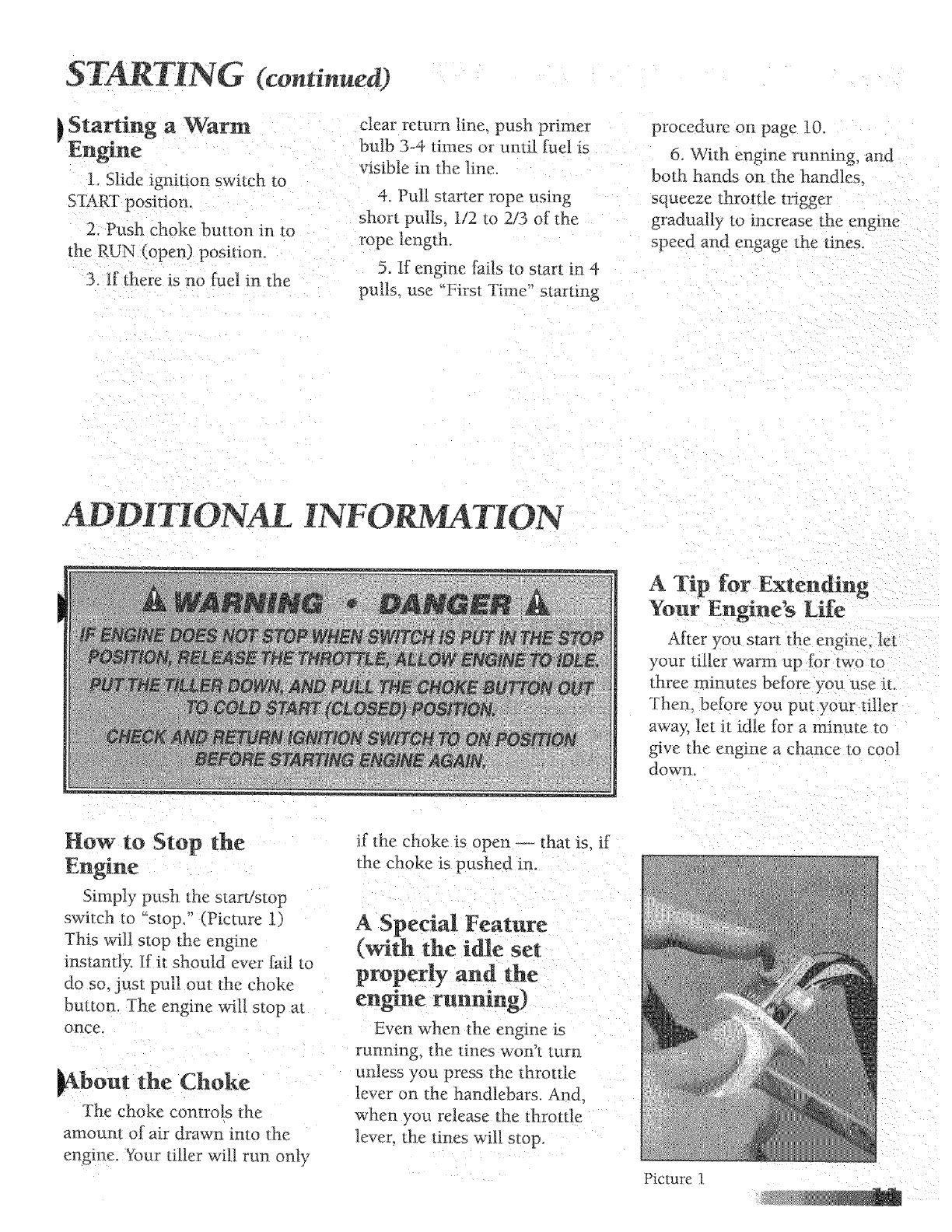
4. Pull out the choke button on choke.
to close the engine Choke. 7. Push in the Choke button
(Picture 2) to open the Choke (Picture 5)
5. Locate the purge bulb on 8. Then pu!! the starter cord
the upper right of the engine, in again. The engine should start
front of (he fuel tank. (See .....
Picture 3) It sends fnel into the
carburetor, for easy starting.
Press the purge bulb until you
see fuel flow through the Ctear
fuel return line. Since you're
starting "cold," you may need to
press six to eight times. As soon
as fuel starts flowing through
the clear _hel line, stop pressing!
(Picture 3)
6. Pull the starter cord
(Picture 4) slowly until
resistance is felt. Then give the
recoil starter cord a tew short,
brisk pulls until the engine fires.
and run. Let the engine warm
up two to three minutes betore
using.
Follow these steps whenever
you are starting the engine "cold",
or when the engine has run dry
and you have just added Jh&
Remember; alwqs use short, brisk
pulls. Don't give the cord a tong,
jbrceJh! yank. And, & not _et the
cord snap bach inw the starter
housing.
Picture 4
Never use starting
fluids as they will
cause permanent
engine damage°
Using them will
void the warranty.
Before you use the
tiller, read the
Safety & Warning
rules on pages 3-6.
Picture 5
Picture 1 Picture 2 Picture 3
STARTING (continued)
}Starting a Warm clear return line. push primer
Engine bulb 3-4 rimes or untiJ fuel is
visible in the line.
I. Slide ignition switch to
START position. 4. Pul] starter rope using
2. Push choke bn_ton in to
the RUN (open) p_.osition.
3 If there is no fuel in the
short pulls. 1/2 m 2/3 of the
rope length.
5. If engl ne fails to start in 4
pulls, use "First Time" starting
procedure on page 10.
6. With engine running, a_cl
both hands on the handles
squeeze tbrottJe trigger
gradually m increase the engine
speed and engage the tines.
ADDI ONAL INFORMATION
ATip for E×tending
Your Engine's Life
After you start, the engine, let
your filler warm up for two ro
three minmes beiore _ ou use it.
Then. before you put your tiller
away, let it idle }.br a minute to
give *he engi ne a chance to cool
do_@,l-i
How to Stop the
Engine
Simply push the start/stop
switch m "stop." (Picture 1)
This will stop the engi ne
instantly If it should ever fail to
do so_ .lust pull out the choke
button. The engine will stop at
once.
_bout the Choke
The choke controls the
arnoum of air drawn in1 o the
engine. Your tilter will run only
if the choke is open --- that is. if
the choke is pushed in.
A Special Feature
(with the idle set
properly and the
engine running)
Even when the engine is
running, the tines won't turn
unless you press the _hrottle
lever on the handlebars. An&
when you release the throttle
lever the tines will stop.
Picture t
TO DO JUST XN
Picture i
Picture2
Picture 3
If you follow the normal
starting procedure, you should
have no problem starting your
tiller. But, just in case you do
have problems, here_ what m do.
Make stay the start/stop
switch is on "start." You'd be
surprised how' many people
forget to push the switch into the
"start" position.
If the switch was on "stop"
when you pulled the cord, you
may have flooded t!le engine.
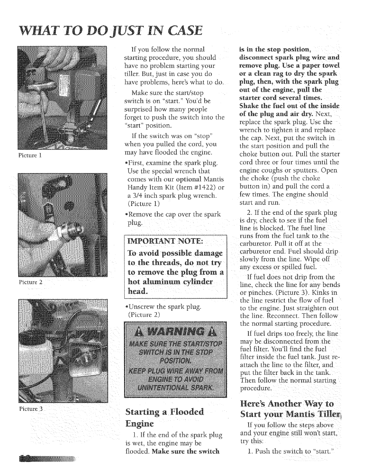
*First, examine the spark plug.
Use the special wrench that
comes with our optional Mantis
Handy Item Kit (Item #1422) or
a 3/4 inch spark plug wrench
(Picture 1)
*Remove the cap over the spark
plug,
IMPORTANT NOTE:
To avoid possible damage
to the threads, do not try
to remove the plug from a
hot aluminum cylinder
head.
*Unscrew the spark ping.
(Picture 2)
is in the stop position,
disconnect spark plug wire and
remove plug. Use a paper towel
or a clean rag to dry the spark
plug, then, with the spark plug
out of the engine, pull the
starter cord several times.
Shake the J[uel out of the k_aside
of the plug and air dry. Next,
replace the spark plug. Use the
wrench to tighten it and replace
the cap. Next, put the switch in
the start position and pull the
choke button ouL Pul! dxe starter
cord three or four times until the
engine coughs or sputters. Open
the choke (push the choke
button in) and pull the cord a
few times. The engine should
start and run.
2. If the end of the spark ptug
is dry, check to see if the fuel
line is blocked. The fuel line
runs from the furl tank to the
carburetor. Pull it off at the
carburetor end. Fuel should drip
slowly from the Jine. Wipe ofl_
any excess or spilled furl.
If fuel does no_ drip tram the
line, check the line for any be nds
or pinches. (Picture 3). Kinks in
the line restrict the flow of _:uel
to the engtae. Just straighten out
the line. Reconnect. Then follow
!_henormal starm tg procedure.
if fuel drips too fred> the line
may be disconnected from the
!:uel Nter. You'll find the t;ael
['iher reside the filel tank. Just re-
attach the line to the [ihec and
put the filter back in the tank.
Then follow the normal start mg
procedure.
Starting a Flooded
Engine
I. H the end of the spark plug
is we__ the engine may be
flooded. Make sure the switch
Here's Another Way to
Start your Mantis
If you t0llow the steps above
and your engine still won't start.
try this:
1. Push the switch to '_starL
WHAT TO DO JUST IN CASE ¢continuea)
2. Push in the choke
but Lon to open the choke,
3, Press the plastic bubble a
few times,
4. Give the starter cord a t_w
short, quick pulls. The m_gine
should start and run.
5. If the engine does not start.
then pull out the choke button
to close the choke. Pull the
starter cord four to I:ive times,
The eng{ne should sputter or
cough.
6. After the engine sputters.
push the choke button in. Then
pull the starter cord. The engine
shou]d start and run,
7. If the engine still does not
start, repeat steps 2 through 6.
8, If the engine still doe_
not start, call 1-800-366-6268
and ask for Customer Service
or the name of your local
Mantis dealer,
IMPORTANT NOTE:
Never use starting _uidso
Starting iluids will cause
permanent engine
damage. Using them will
void the warranty.
IMPORTANT NOTE:
Before you use your
Mantis Ti|ler, read the
Safety Rules & Warnings
on pages 3-5.
GETTING YOUR TILLER TO YOUR GARDEN
Walk it.
Once your tiller is running,
you car_ '_walk" it to your
}garden, Just press the throtde
Icy er gently and let the viler
_'lip-toe" across your yard on its
tines. It won't hurt your lawn or
driveway, (Picture t)
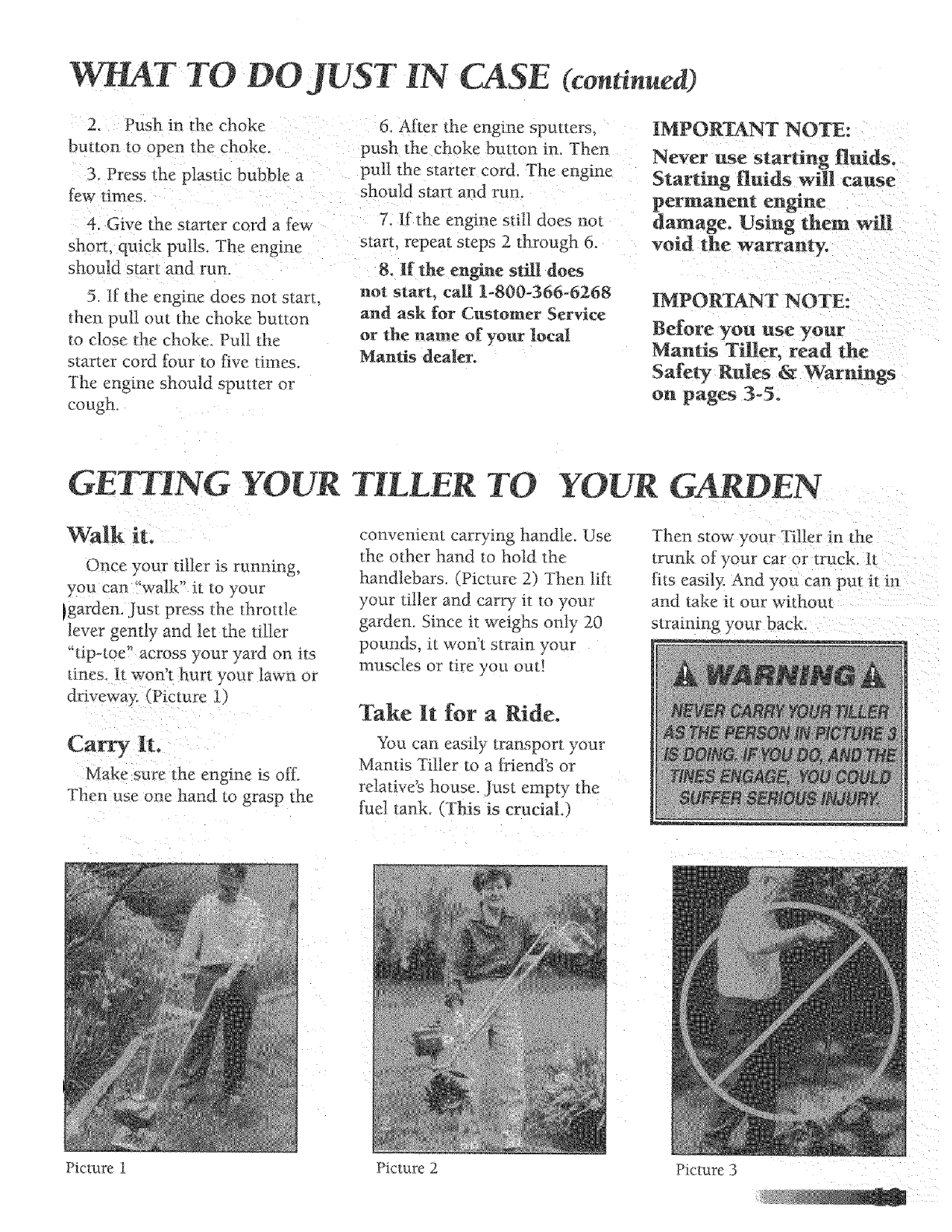
Make sure the engine _s oK
Ther_ use on e hand Wgrasp the
convenient carrying handle. Use
the other hand to hold the
handlebars. /Picture 2) Then lift
your tiller and carry it _o your
garden. Since it weighs only 20
pounds, it w_ n't strain your
muscles o_ tire you out!
Take It for a Ride.
You can easily transport your
Mantis Tiller to a friend's or
relative's house. Just empty the
[ue] lank. (This is crucial.)
Then s_ow your Tiller in the
trunk of your car or truck. It
fits easily. And you can put it in
and take it our withou_
straining your back
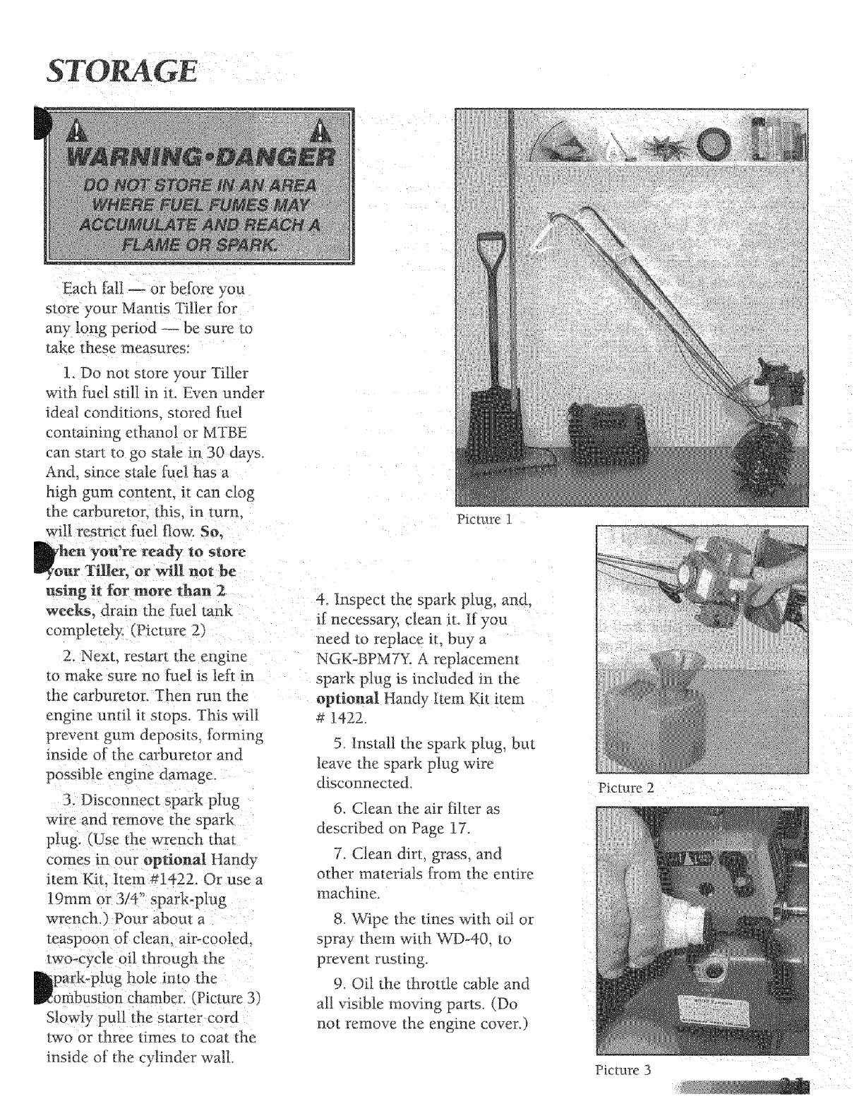
Picture i Picture 2 Picture 3

TILLING
Picture 1
Picture 2
Picture 3
Now You're Ready to
Use *four Mantis Tiller.
If you've seen other tillers,
your Mantis Tiller may surprise
you. It tills best when you pull it
backward! You see, when you
pulI your Mantis Tiller backward,
you give extra resistance to the
tines, so they dig deeper.
(Picture 1)
What's more when you go
backward, you erase your
footprints. So your soil stays light
and fluffy. With other tillers, by
contrast, you walk right over the
soil you've just tilled, packing it
down, so it's less plamable.
Run Your Mantis Tiller
like a Vacm_lm Cleaner.
Place your Tiller at the head of
the row or area you want to till
Start it up. Then use an eas?
rocking motion. First. pull your
Tiller backward. Then use an
easy rocking motion. Again, pull
your Tiller backward. Then. let il
move torward just a little bit.
Then pull it backward again.
This will h@ you till deeper.
Keep repeating these steps
until you've Oiled an enure row:
Start again on the next row. It's
much like running a vacumn
cleaner[ (Picture 2)
You Can Even Control
Depth.
For Deeper Tilling:
Move your "Filler slowly back
and forth, as you would a
vacuum cleaner, Work the same
area over and over until you've
dug to your desired depth.
For Shallow Tilling!
Switch the tines tO the
cultivating position. (Seepage
15 to learn how.)Then move
your Tiller quick!y over your
soil surface ...............
For Big Weeds or Tough Roots:
Let your Tiller rock back and
_orth over the tough spot, until
the tines slice through the weed
or root.
Your Mantis TNer Handles
Want to turn part of } our lawn
into a color[;al flower border?
Your Mantis "filler makes _t easy!
Just run your Tiller back and
[)rth until the sod begins to
break up. Then continue tilling_
Your 7[ilter will chop the clumps
of sod until they're line, Then. :it
-will work them into the soil
Pretty soon, ym£1t have a soft.
fresh planting bed.

TILLING/CULTIVATING
How about a family-sLze
vegetable garden?
Nowadays many gardeners
prefer small gardens
especially in _he suburbs, vd rare
space is at a premmm But. if
you're fortunate enough to own
a large lot, you can create a
bJgger garden a half acr_ or
more. Here's how:
1. First hire someone with a
tractor ar big tiller to break
is a on e-
[y i_westme'nt _hat_ welt
worth the small cos_.
2. Then. use your 1Tiller to
break up any remaining clumps
of soil or sod. Unlike a tractor
or big tiller, your Mantis Tiller
ts a prectsion tno!. _r will
pulverize your soil into a
smo_th seed bed.
Picture ] Picmre 2
Your Mantis Tiller Makes How to Switch From
Weeding a Pleasure! Tilling to CuRivating
As a tiller, your Mamis Filler
works the soil down to 10"
(25.4 cm) deep. But, as a
cultivator, it gently cultivates
the surface, only 2" to 3" (5.09
cm to 7.62 cm) deep.
First. }ou must switch _he
_nes to the ,weeding position.
this takes less than a mi_me.
Then your Mantis Tiller's
sharp "'line teeth" will slice up
those pesky weeds, burying
them as you go along, And.
since the tines in this position
won't dig too deep, they won'_
hurt your plants' precmus rool
svsterrls_
The resuh? Your Tiller witl
cm your weeding time in half.
and turn a tiresome chore into a
pleasure.
Position
1. Make sure your "Filler of
oK
2. Remove the retaining pins
from the tines.
3. Rein ove the trees J:rom the
axle.
4. Place the right-side tine
ohm the left-side axle. Place the
left side tree onto t he right-side
axle. The _'D" hole simuld be to
the outside.
5. Here is how to make sure
you've installed the ti rtes
properly. Stand behind Lhe Tiller
and hold your hand, palm up,
next to the _ines. Do the tint
points cuff u p, as your fi ngers
do? If so. they are in d_e correct
cultivating position.
O Reinserl the pins.
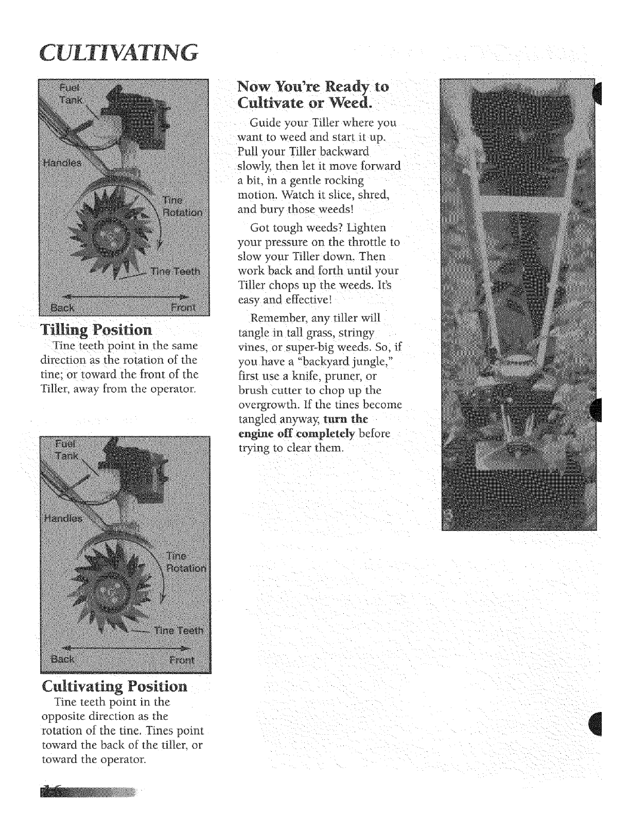
CULTI¥ TING
Tilling Position
Tine teeth point in the same
direction as the rotation of the
tine: or toward the from of the
TilleL away from the operator.
Now You're Ready to
Cuhivate or Weed.
Guide your Tiller where you
want to weed and start :it up.
Pull your Tiller backward
slowtF_ then let it move forward
a bit. in a gentle rocking
motion. Watch it slice, shred,
and bury those weeds!
Got tough weeds? Lighten
your pressure on the throttle to
slow your Tiller down. Then
work back and forth until your
Tiller chops up the weeds. It's
easy and effective!
Remember. any tiller will
tangle An tall grass, stringy
vines or super-big weeds, So. if
you ;have a "backyaTd jung]e,
first use a knife_ pruner, or
brush cutter to chop up the
overgrowth. If the tines become
tangled awwa_: turn the
engine off completely before
trying to clear them.
Cultivating Position
Tine teeth point in the
opposite direction as the
rotation of the tine. Tines point
toward the back of the tiller, or
toward the operator.
MAINTENANCE
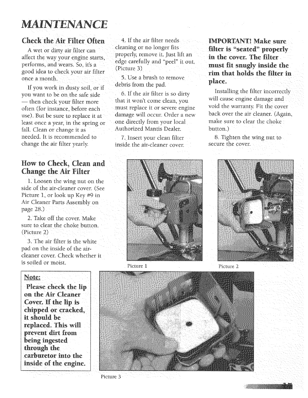
Check the Air Filter Often
A wet or dirty air filter can
affect the way your engine starts.
performs, and wears. So it's a
good idea to check your air filter
once a ntonth_
If yon work in dust?- soil. or if
you want m be on the safe side
then check your filter more
often {for instance, betbre each
use). But be sure to replace it at
least once a year. in the spring or
fall. Clean or change it as
needed, it is recommend{_d to
change the air filter yearly.
4. If the air filter needs
cleaning or no longer fits
properly, remove it. lust litt an
edge carefully and "-peel" it out.
(Picture 3)
5_ Use a brush to remove
debris from the pad.
6. If the air filter is so dirty
thin it won't come clean, you
must replace it or severe engine
damage :,*Alloccur. Order a new
one directly from your local
Authorized Mantis Dealer.
7. Insert your clean filter
inside the ai>cleaner cover.
IMPORTANT[ Make sure
filter is "seated" properly
in the cover. The [Rter
mus_ fit snugly inside the
rim that holds the filter in
place.
Insta!ling the filter incorrectly
will cause engine damage and
void the warranty: Fit the cover
back over the air cleaner, (Again.
make sure _o clear the choke
button,)
8. Tighten the wing nut to
secure the cover.
How to Check, Clean and
Change the Air Filter
!, Loosen the wing "nut on the
side of the air-cleaner cover. (See
Picture 1. or look up Key #9 in
Air Cleaner Parts Assembly on
page 28.)
2. Take off the cover. Make
sure to clear the choke button,
vPicture 21
3. The air filter is the white
pad on the inside of the air-
cleaner cover. Check whether it
is soiled or moist.
Please check the lip
on the Air Cleaner
Picture 1
replaced. This will
through the
carburetor into the
Picture 3
Picture 2
MAINTENANCE (continued)
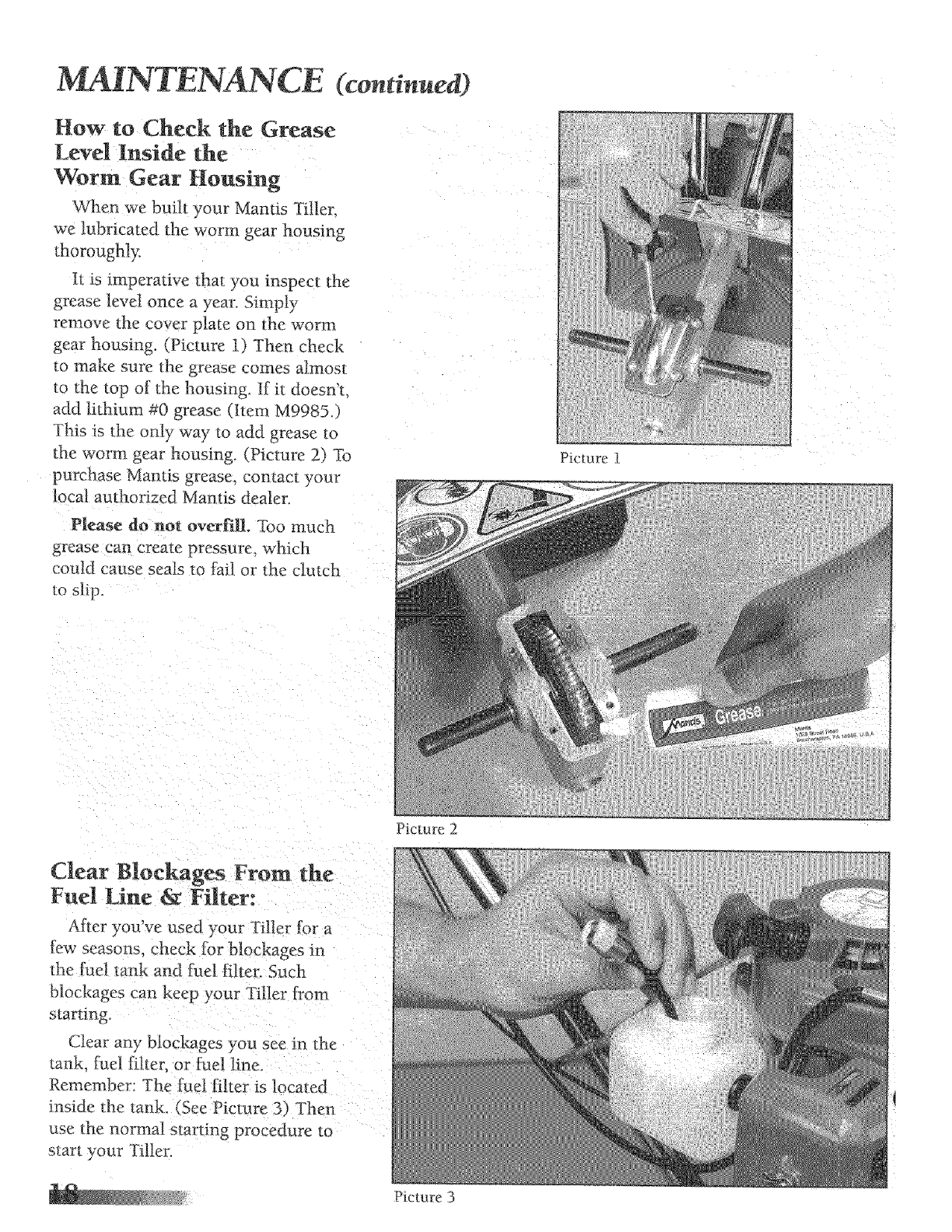
How to Check the Grease
Level inside the
Worm Gear Housing
When we built your Mantis Tiller.
we lubricated the worm gear housing
thoroughly.
it is imperative that you inspect the
grease level once a year. Simply
remove the cover plate on the worm
gear housing. (Picture i) Then check
_:omake sure the grease comes almost
to the top of the housing. [f i_ doesn't.
add lithium #0 grease (Item M9985.1
This is the only way to add grease to
the worm gear housing. (Picture 2) To
purchase Mantis grease, contact your
local authorized Mantis dealer.
Please do not overfill Too much
grease can create pressure, which
could cause seats to fail or the clutch
to slip_
Picture 2
Picture 3
Picture 1
Fuel Line & Filter:
After you've used your Tiller for a
few seasons, check for blockages in
the fuel tank and fuel Nten Such
blockages can keep your Tiller [:rom
starting.
Clear any blockages you see m the
tank. fuel fihec or Fdel line.
Remember: rhe fuei filter is located
inside the tank_ (See Picture 3} Then
use the normal starting procedure to
start your Tiller.
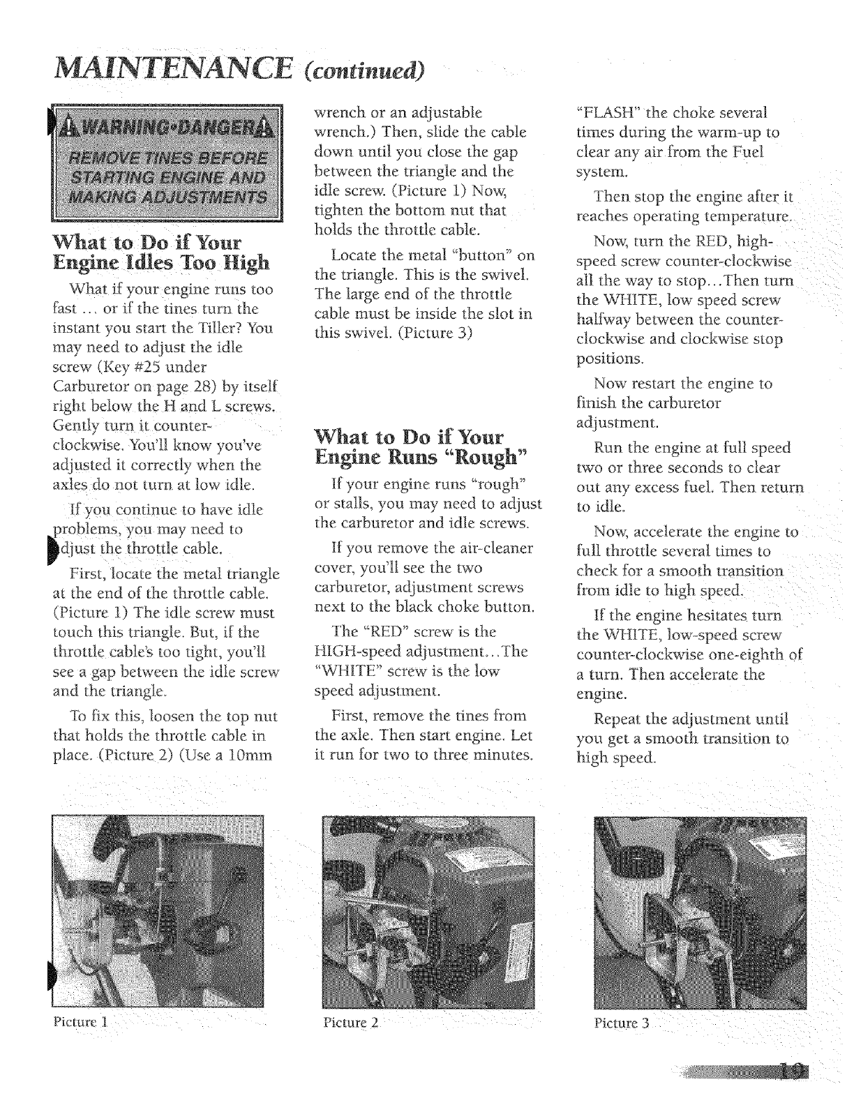
What if your engine runs too
fast ... or if the tines turn the
instant you start the Tiller? You
may need to adjust the idle
screw (Key #25 under
Carburetor on page 28) by itself
rigbt below the H and L screws.
Gently turn it counter-
clockwise. You'll know you've
adjusted i_ correctly when Lhe
axles do no_ turn at k)w idle.
tf you con_itme to have idle
.problems, you may need ro
ldjust the throule cable.
Filst. locate the metal Lriangle
at the end of the throtde cable.
(Picture 1) The -idle screw mus_
touch this triangle. But, i[ _he
throttle cabie_ too light, you'll[
see a gap between the idle screw'
and the triangle
to fix this. loosen *he top nttt
that holds _he throvle cable in
place. (Picture 2) (Use a 10ram
(cominued)
wrench or an a_ustable
wrench.) Then, slide the cable
down until you close the gap
between the triangle and the
idle screw. (Picture 1) Now,
tighten the bottom nut that
holds the throttle cable.
Locate *:hemetal "button" on
the triangle. This is the swivel.
The large end of the throttle
cable must be inside the slot in
this swivel. (Picture 3)
What to Do if Your
Engine Runs "Rough"
tf your engine runs "'rough"
or slalls you may need Loadius_
the carburetor and idle screw's.
tf you remove the ai>c]eaner
cove_, you'll see the two
carburetor, adjustment screws
nex_ to the black choke button.
The "RED" scre_ is the
HIGH-speed adiustment...The
"WII[TE" screw is the low
speed adjusm_em.
First_ remove (he rmes [rom
the axle. Then start engine. Let
it run [:or two to _hree rmnutes.
"FLASH" the choke several
times during the warm°up to
clear any air [rom the Fuel
system.
Therl stop the engine after it
reaches operating temperature.
Now; turn the RED, high-
speed screw counter-clockwise
all the way to stop...Then turn
the WHITE> low speed screw
halfway between the counter-
clockwise and clockwise stop
positions.
Now restart the engine to
finish the carburetor
adjustment.
Run the engine at lull speed
two or three seconds to clear
out any excess [uel. Then return
to idle.
Now. accelerate the engine _n
lul!l 1hrott/e several times _o
check _br a smooth tra nsition
[?om idle to high speed.
[[ the engine hesitates turn
the WHIT[_ low-speed screw
counter-clockwise one-eighth o[
a turn. The:n accelerate the
engine.
Repeat the adjustment umi!
you get a smooth trans:mon to
high speed.
Piclure 1 Picture 2Picture 3
MAINTENANCE
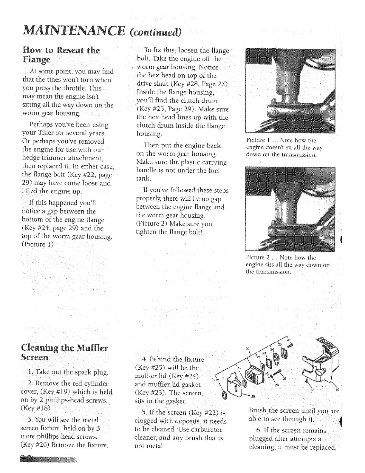
How to Reseat the
Flange
At some point, you may {:ind
that the tines won't turn when
you press the throttle. This
may mean the engine isn't
sitting all the way down on the
worm gear housing.
:Perhaps you've been using
your Tilter for several years.
Or perhaps you've removed
tile engine ibr use with our
hedge trimmer attachment,
then replaced it. In either case,
the flange bolt (Key #22, page
29) may have come loose and
notice a gap bet_zeen the
bottom of the engine flange
(Key #24, page 29) and the
top of the worm gear housing.
(Picture 1)
(continued)
To fix this, loosen the flange
bolt. 'lake the engine off the
worm gear housing. Notice
the hex head on top of the
drive shaft (Key #28, Page 27),
Inside the flange housing,
you'I1 find the clutch drum
(Key #25, Page 29). Make sure
the hex head lines up with the
clutch drum reside the flange
housing.
Then put the engine back
on the worm gear housing.
Make sure the plastic carrying
handle is not under the fuel
tank.
If you've followed these steps
properly, there will be no gap
between the engine flange and
the worm gear housing.
(Picture 2) Make sure you
tighten the flange bolt!
Picture 1 _. Note how _he
engine doesn't sit all the way
down on the transmission.
Picture 2 .._ Note how the
engine sits all the way down on
the transmission.
Cleaning the Muffler
Screen
]. Take out the spark plug.
2. Remove the red @inder
cover, (Key #19) which is held
on by 2 phillips-head screws,
(Key #18
3. You will see _he metal
screen fixture held on b) 3
more phillips-head screws.
(Key #26) Remove the fixture
4. Behi nd the fixture
(Key #25) will be the
muffler hd (Key #24)
and muffler lid gasket
s_ts in the gasket.
5. If the screen (Key _22 }is
clogged with deposits, it nee&
to be cleaned. Use carburetor
cleaner, and any brush that is;
noc metal.
_8 {9
Brush t ae screen until you are
able to see through it.
6. If the screen remams
plugged after attempts al
cleaning, it must be replaced
STORAGE
Each fall -- _r before you
store your Mantis Tiller for
any long period be sure to
take these measures:
1. Do not store your Tiller
with [k_el stil! in _t. Even under
ideal conditions_ stored fuel
containing ethanol or MTBE
can star{ to go stale in 30 days.
An& since stale fuel has a
high gum content, it can clog
the carburetor, this, in {urn,
will restrict fuel i]ow. So,
en you're ready to store
_r Tiller. or will not be
u._ing it for more than 2
weeks, drain d_e fuel tank
completel}¢ (Picture 2)
2_ N ext. restart the engine
to make sure rm fuel is left in
the carburetor. _ hen run the
engine until it stops. This -,viii
prevent gum deposits, forming
inside o[ the carburetor and
3. Disconnect spark plug
wire and remove the spark
plug. (Use the wrench thin
coJ ties in our optional Handy
item Kit_ Item #142X Or use a
19ram or 3/4" spark-ping
teaspoon of clean, ai>cooled
p,vo_c,¢cle oil through the
park-plug hole into the
ombus_ion chamber. (Picture 3)
Slowly pull the starter cord
two or three times to coat the
inside of the cylinder wall
Picture I
4. Inspect the spark plug, and,
if necessary, clean it. If you
need to replace it. buy a
NGK-BPM7Y. A replacemem
spark plug is included in the
optiouM Handy item Kit item
1422.
5. install the spark plug, but
leave the spark plug wire
disconnected.
6. Clean *.he air filter as
described on Page 17
7. Clean dirt grass, and
other materials from the em_re
machine.
8. Wipe the tines with oil or
spray them with WD-40. m
prevent rusting.
9. Oil the throttle cable and
all visible moving parts. (Do
no_ remove the engine cover.)
Picture 2
Picture 3
STORAGE (continued)
10. Check the grease level in
the worm gear housing, as
described on page 18.
II. Order new parts to
replace any that are badly
worn or broken. Just contact
your local authorized Mantis
dealer. But do it early, so you'll
have the parts well before the
he× t gardening season starts.
12. Store you Tiller -- in an
upright position it, a clean.
dry place (Picture t. preceding
page)
13. Do you have fuel left over
[rom last season? Dispose of it
properly. Buy fresh oil and
gasoline next season.
Haw to Prepare Your
Mantis Tiller ['or
Restarting
In the Spring, when yon take
yo ar 2511er om of storage,
remove the spark plug. Pull the
starter cord three or four times
to clean oil from the combustion
chamber. (Picture 1) Wipe oil
from the spark plug. Place the
spark plug back into *he
cylinder. Re-connect the spark
plug wire back on the spark
plug, Then fbllow *he sleps on
pages 9 & 10 to retuet and
restart your Tiller.
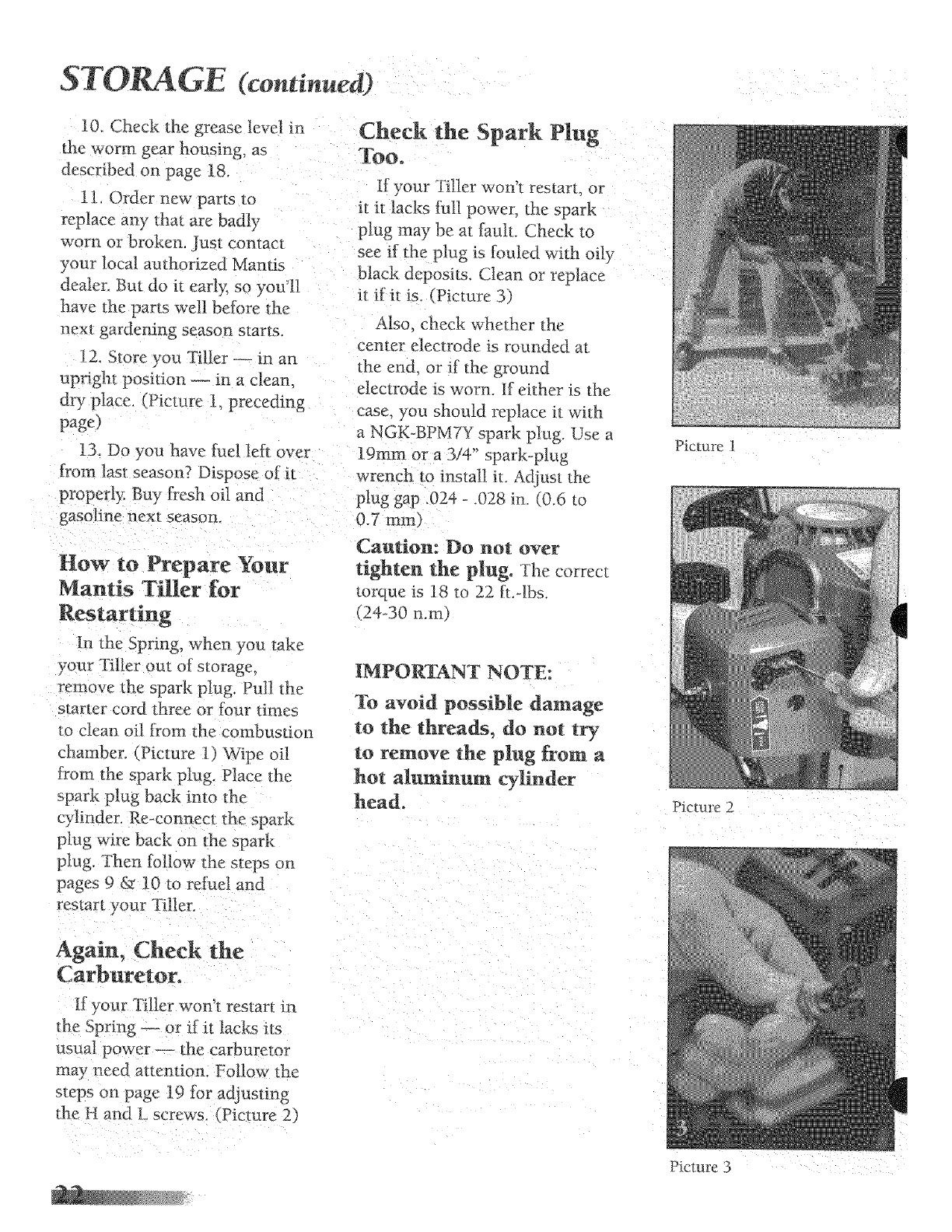
Check the Spark Plug
Too.
I[ your Till er won'L restart_ or
it it lacks ful] power, the spark
plug may be at fauh Check to
see if the plug is tbuled with oil)-
black deposits. Clean or re place
it if it is. (Picture 3 )
Also check whether the
center electrode is rounded at
the end. or if the ground
electrode is worn. If ei*her is the
case. you should replace it with
a NGK-BPM7Y spark plug. Use a
19mm or a 3/4" spark-plug
wrench m inslall it Adiust the
pluggap 024 .028 in (0.6 to
0.7 ram)
Caution: Do not over
tighten the plug. The correct
torque is 18 to 22 |L-lbs.
(24-30 n.ma
IMPORTANT NOTE:
£o avoid possible damage
to the threads, do not try
to remove the plug from a
hot aluminum cylinder
head.
Again, Check the
Carburetor.
K your Tiller won'_ restart in
the Spring _ or if it lacks its
usual power _ _he carburetor
may need attention. Follow Lhe
s_eps on page I9 for adjusting
the H and Lscrews. (Picture 2)
Picture 1
Picture 2
Picture 3

TROUBLE SHOOTING
Problem
P
Cause
Tines don't turn when throttle
is depressed
2. Engine fails to start
Engine hard to star_.
4. Engine misses,
Engine is not seated properly on
the gear housing.
Start/Stop switch is in Stop
position.
No fuel in tank.
Fuel s_rainer clogged.
Fuel line clogged.
Re-install engine tbllowing the
instructions on page 20 (How to
re-seat the flange).
Move switch to start
Fill Tank.
Replace Strainer.
Clean [uel line.
Spark plug shorted or fouled. Install new spark plug.
Spark plug is broken (cracked
porcelain or electrodes broken)
Ignition lead wire shorted.
broken or disconnected from
spark plug.
lgnition inoperative
V_Zaterin gasoline or stale fuel
mixture.
Too much oil in [uel mixture.
Engine under or over choked
Carburetor out of adjustment
Gasket leaks (carburetor or
cylinder base gasket).
Weak spark at spark plug.
Dirl in fuel line or carburetor.
Carburetor improperly adjusted.
Spark. plug fouled, broken or
incorrect gap setting.
Weak or intermittent spark at
spark plug.
Replace spark plug.
Replace lead wire or attach to
spark plug.
Contacl your local authorized
dealer.
Drain entire system and re[ill
with fresh fuel.
Drain and refill with correct
mixture.
If flooded by over choking,
proceed according to
instructions in operation
section. _f under choked_ move
choke lever to closed position
and crank two or three times_
See "Carburetor Adjustmem
Replace gaskets.
Contact your local authorized
dealer.
Remove and clean.
See "Carburetor Adjustment_
Clean or replace spark plug - se_
gap to .024-.028 in. _0_6-0.7 mm 1
Contact yore" local authorized
dealer.
TROUBLE SHOOTING
Problem
5. Engine lacks power.
6. Engine overheats.
7 Engine nmsy or knocking.
8 Engl ne stalls under load.
Air tilter clogged
Carburetor out of adjustment.
Mu[tler clogged.
Clogged exhaust ports.
Spark Arrestor Clogged
Poor compression.
Insufficient oil in fuel mixture
Air flow obstructed
Spark plug in incorrect heat range.
Bearings, piston ring or cylinder
walls are worn.
Carbure _or adjustmem too "lean".
Engine overheat s.
Re]rlTtedy -4
Clean or replace air filmr.
See "Carburetor Ad}nstmenU.
Clean carbon [rom nmNer.
Remove muffler, rotate engine
until the piston is as hop of
cylinder. With a wooden
scraper or blunt tool. remove
aH carbon from exhaust ports.
Be careful not to scratch or
damage piston or c}'li ader
walls. Blow _)ut all loose carbon
with compressed air. Install
muffler and gasket.
Ctean Spark Arrestor
Contact your local authorized
dealer.
Mix thel as described in starting
instructions.
Clean flywheel cylinder fins and
screen. -!
Replace with plugs specified for
engine.
Contact your local authorized
dealer.
See 'Carburetor Adiusm_em"
Remove dust ane dirt [rmn
between fins.
ENGINE SPECIFICATIONS
Dry Weight
Type of Engine
Rotation
Bore
Stroke
Spark Plug
Fuel
Fuel Oil Ratio
Gasoline
Exhaust System
Carburetor
Ignition System
Starter
Oil
Fuel "lank Capacity
Starter System Clutch
2.5kg 5 lbs., 10 ounces
Air Cooled, Two stroke, Single-Cylinder. Gasoline 7Engine
Clockwise. viewed t:rom TOP
32.2 mm (1.268 in.)
20.0 mm I 1.04 in,)
NGK BPM7Y
Premixed two stroke t:uel
50:1 ratio with Mantis oil
Unleaded {see page 9)
21 2 cc (t.294 cu. in.)
Spark arrestor muffler
ZAMA diaphragm model C1U type
Flywheel magneto, capacitor discharge ignition type
Automatic rewind type
Designated. two-stroke, air-cooled engine oil
0.4 tit. (13.57 oz.)
An1 ornat_c rewind starl er Cen trifngal type

GUXDE
Maintenance Frequency
Air Filter Daily or every 4 hrs. use
Every 3 mths, or 100 hrs, use
Spark Plug Every 3 mths. or 100 hrs, use
6 months or 300 hrs, use
Carburetor 6 months or 300 hrs. use
Yearly or 600 hrs, use*
Cooling System Bei0re Use
Muffler (Spark Arrestor) Monthly
Gear Housing Yearly
Blades After Use
Fuel Leaks Bet_re Use
Fasteners Before Use
Labels Before Use
Handles Before Use
Guards /Safety Devices Before Use
Fuel Line Monthly
Monthly
Every 3 mths, or 100 hrs, use
IFuel Strainer
Choke
Clean
Replace
Clean
Replace
Check /Rebuild
Replace
Inspect /Clean
Inspect /Clean
Check Grease
Inspect /Clean /Lubricate
Inspect /Repair
inspect /Tighten /Replace
Inspect /Replace
Inspect /Replace
Inspect /Replace
Inspect /Replace
Inspect /Replace
Replace
Check
Clean
Replace
l
With each re-flaeling
No maintenance
For coil and flywheel
* Replacemem will be reqt_ired 5_r commercial use after 600 hours For Cormmner use, cleamng every 6 mo_ths is required. Cleaning inch_dcs Rehttild K_s,
IMPORTANT: Time Intervals shown are maximum. Actual use and your experience will determine the
frequency of required maintenance,
No_es:

USING THE BORd ER EDGER ATTACHMENT
Your Mantis "_Fillerhas been
designed and built to accept a
wide range of Mantis Tiller
Attachments to increase its
usefulness in your lawn and
garden. And, all Mantis Tiller
Attachments have been
designed for quick and easy
attachment to the Tiller or
Engine,
The Border Edger
(Item #3222)
The most popular
attachment, the Border Edger
can be used to cut clean, neat
edges along walkways, or
around trees, shrubs, and
garden beds.
The Border Edger has two
parts: a wheel and a hardened
steel blade, with pointed tines.
How to Install the
Border Edger
The following instructions
rd?r to "right" and "left" axles.
Assume that you're standing
behind your Tiller, as you
would fbr tilling and
cultivating.
Some areas of your yard may
harbor roots and other
underground obstructions. In
places like this you'll want to
edge your borders shallowly (1"
to 2" deep). Here's how to
install the Border Edger for
shallow edging:
1. First remove your
tilling/cultivating tines.
2. Then slide the edger's
wheel onto the right axle.
3. Now slide the Edger blade
onto the left axle. The blade's
angled tace should hit the
ground when you spin the blade
forward.
4, Insert retaining pins on
both left and right axles.
Around walkways and garden
beds, you'll want to edge more
deeply (3" to 4" deep). Here's
how"to install the Border Edger
fbr that purpose:
1. Remove the
tilling/cultivating tines.
2. Slide the Edger's blade onto
the right axle. The blade's
pointed face should hit the
ground when you spin the blade
forward.
3. Slide the wheel onto the
left axle.
4. Insert retaining pins on
both sides.
q
How to Use the
Border Edger
1. Position your Mantis Tiller
so that the Edger blade is right
along the garden edge and the
Wheel is outside (on the lawn,
on the sidewalk, wherever).
(Picture 1)
2. Start your Tiller and pull
your Mantis backward along the
garden edge. (Picture 2)
The Border Edger Can
Handle Special
Projects!
1. Install the Edger tbr deep
edging, as directed above. The n"
use it to cut sod strips.
2. Edge and ,weed at the same
time[ Just attach the Edger
blade on one axle and a Tiller
tine on the other axle, "Mix and
match" blades; don't be aDaid to
experiment.
IMPORTANT NOTE:
If you do a lot of edging,
you'll appreciate the
Mantis Wheel[ Set
(Item#9222.) It gives you
added stability, for even
easier banning.
To order the wheel Set, or
any MantAs Attachment, ........
contact your local aumodzed 4
Mantis dealer.
Picture 1 Picture 2

NTIS TILLER ASSEMBLY
23
3435 54 38 42 42 32
55
...... 47
17
16
18
P/N 438LA
DIRECTION
Raise_t Hub
Teeth
a Clockwise
Direction
When yet1 look at a Tirm witlt the rab,ed hub facing yo_
and the teeth are pmming in a CL_NWISE _'o_ation,
you have _:_LEV_ !tAND TINE_
P/N 438RA
DIRECTION
Ra}sed Hub
_ointi_
aCount_
ClockwiSe
Direcliot_
When you look at 'l'J_ac with the raised hub tacing you
and the Iectb are poit_ting i_n a COUNTER CLOCKWISE
'¢ _ation, veu a_ad a NtrG}TF HAND 7[INE,
g_v P_!_ Qrf, DESCRtFrION
NO.No.
1 382 1 Throttle Lever
2 383 1 Gfip-Thru
3 619 1 Grip
4 4062 1 Upper Handle -w!o Throttle
5 4061 1 Upper Handle _with Throttle
6 4063 2 Lower Handle
7 48gM I Label
8 148 1 Handle Brace
9 464 1 Switch Bracket
KE:_'PAtti Qr**DEsc_VrlON
No, No.
21 467-2 1 Throttle Cable Ass,/.
22 377 2 Handle Clamp
23 470 2 Long Bolt 1/4-20 x 3" Lg.
25 465 1 Fender Guard
26 140 2 Bold 1/4-20 x 3/8" Lg.
27 380E_4B1E 1 (Qt>) Engine
28 468 1 Drive Shaft
29 466 1 Worm Gear Housing
31 436 1 Gasket
KF_PAR-r@o DEscmmoN
No. No.
341431 1 Tine Shaft
42 430 2 Worm GearThrust Washer
43 432 2 Worm Gear Bearing
44 434 2 Bearing Seat
45 435 2 Bearing Seal Retainer
46 438RA 1 Tine Assembly (RM)
47 438LA 1Tb_eAssembly (LM,)
48 4184 2 1-ineRetaining !tair Pin
49 402 1 Carryirtg HanOe
!0 479 1 Switch
II 410 4 CapScrewl/4-20xI'Lg.
12 972 6 LockNut 1/4-20
5 478 2 ThrottleClip
6 477 1 Connector Female
17 476 1 Connector Male
18 4075 1 GrotmdWire
19 379 2 Cable Retainer
20 413 t Retair_ingRing
32 437A i Housing Cover
33 651. 1 Rd. Hd. Sdf Tapping Screw
34 423 1 Roller gearing
35 425 1 Worm Bearing Race
36 424 ! Worm Thrust Bearing
37 422 1 WormSMfl
38 426 1 Worm Disk
39 428 1 Retaining Ring
40 429 1 Worm Gear
50 487MA 1 Engiue Label
51 4043 1 TineLabet
53* AA7222 Trans -Transmission Assembly
54 458 ! Roller Bearing
55 4058 IMantisLabd
56 1612-70A l SwitchCover
*Doesnot includeKeyor #48 wkransmission
'P/N468IsincludedmAA72224rans.
S%4B1E ENGINT PARTS ASSEMBLIES
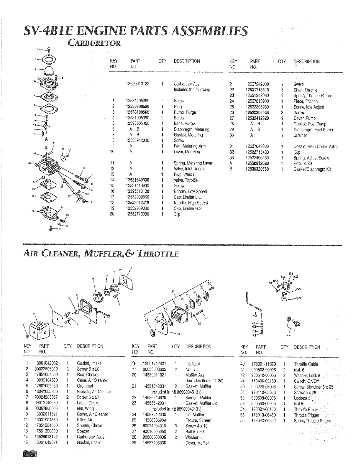
CA_U_TOR
KEY PART QTY DESCRIPTION KEY
NO, NO, NO.
PART QTY DESCRIPTION
NO.
A
12520013122 1 CarburetorAsy 21
Includesthe following: 22
29
t 12534405360 2 Screw 24
2 1253&108560 1 Ring 25
3 12538108660 1 Pump,Purge 26
4 12531005360 2 Screw 27
5 12538305360 1 Base, Purge 28
g A B ! Diaphragm,Metering 29
7 A B 1 Gasket,Metering 30
8 t2533942030 ! Screw
9 A 1 Pen,MeteringArm 31
10 A 1 Lever,Metering 32
33
11 A 1 Spring,MeteringLever A
12 A 1 VaNe,InletNeedle B
13 A 1 Plug,Welch
14 12581649030 1 Valve,Throttle
15 12531413930 I Screw
16 12531813120 1 Needle,Low Speed
17 12532909860 1 Cap,LimflerL.L
18 12532013310 1 Needle,HighSpeed
19 12532939030 1 Cap,LimiterH,S,
20 12532713930 I Clip
12837242030 1 Swivei
12531713810 1 Shaft,Thtott!e
12531342030 1 Spring,Thre_leReturn
12537813930 1 Piece,Friction
12533306960 1 Screw,IdleAdiust
12533306960 2 Screw
12582412820 1 Cover,Pump
A B 1 Gasket,Fuei Pump
A B 1 Diaphragm,FuelPump
A I Strainer
12537649030 1 No_te, MainCheckVaNe
12532715130 1 Clip
12533406560 1 Spdng_Adjust Screw
12530012820 1 RebuildKit
12530320560 1 GaskeL/DiaphragmKit
AIR CL NER I J[UFFLER,& T RO TLE
L
KEY PART QTY DESCRIPTION KEY PART QTY DESCRIPTION KEY PART QTY DESCRIPTION
NO. NO NO NO. NO NO.
1 18001042082 1 Gasket,intake
2 90023805020 2 Screw5 x 20
3 17851004560 1 Rod,Choke
4 13030104560 1 Case,Air Cleaner
5 17881005280 1 Grommet
6 13041005360 1 Bracket,Air Cleaner
7 90024205057 2 Screw5 x 57
8 89012140630 1 Label,Choke
9 90052800005 1 Nut, Wing
10 13032611521 1 Cover,Air Cleaner
11 13031004560 1 Filter,Air
12 17851504560 ! Shutter,Choke
13 17851600830 ! Spacer
14 12620018122 1 CarburetorAssy
t5 13001642031 1 Gasket,Intake
16 13001742031 1 Insulator
17 90050000005 2 Nut 5
20 14580011821 1 MuffterAsy
{includesitems21-26)
21 14551042031 2 Gasket,Muffler
(tociudedin Kit88900045131)
22 14586240630 1 Screen,Muffler
23 14586642031 1 Gasket,MufflerLid
(Includedin Kit88900045131)
24 14587642030 1 Lid,Muffler
25 t4586306960 ! Fixture,Screen
26 90024204010 3 Screw4 x 10
27 90010505050 2 Bolt 5 x 50
28 90060000005 2 Washer5
29 14587105360 I Cover,Muffler
40 178001q 1820 1 ThrotileCabte
41 900502_00006 2 Nut,6
42 900610_00006 2 Washer,Lock6
44 163400_02160 1 Switch,On/Off
50 900220-05028 1
51 178110_05330 t Screw5 x 28
52 900500*00005 1 Locknut5
53 900560_00005 1 Nut 5
54 178024-06130 1
55 178010_06460 1 ThrottleTrigger
56 178043-05230 1 SpringThrottle Return
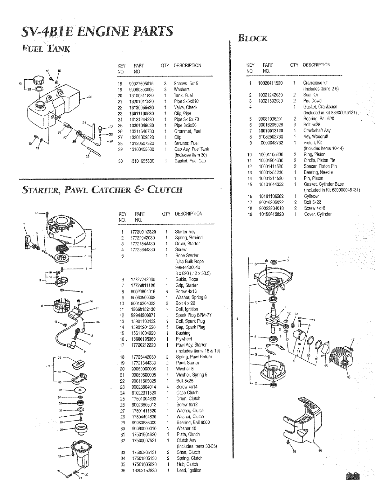
S%4B I E ENGINE,PARTS
FUEL TANK
18 19
KEY PART QTY DESCRIPTION
NO. NO.
18 90027505015 3 Screws 5x15
19 90060300005 3 Washers
20 13100511820 1 Tank,Fuel
21 13201011520 1 Pipe3×5×210
22 13130056430 1 Valve,Check
23 13011106530 1 Clip, Pipe
24 13131244330 1 Pipe3×5× 70
_8 _ 28 13211546730 1 Grommet,Fuel
27 13201309820 1 Clip
_7 24 28 13120507320 i Strainer,Fuel
29 13100453530 1 Cap Asy,FuelTank
(IncludesItem30)
30 13101655830 1 Gasket,Fael Cap
ST4RTER, PAWL CATCHER &CL_)TCH
6 5
t
17 4
_e
KEY PART QTY DESCRIPTION
NO. NO.
1 17720012820 1 Starter Asy
2 17722042030 1 Spring,Rewind
8 17721644430 1 Drum,Starter
4 17723644330 1 Screw
5 1 RopeSiarter
(Use SulkRope
99944400040
3 x 890 (J2 x 33,5)
6 17727742030 1 Guide,Rope
7 17728811120 1 Grip,Starter
8 90023804016 4 Screw4x16
9 90060500008 1 Washer,Spring8
10 90016204022 2 Bolt4 x 22
I1 15660152130 1 Coil,ignition
12 99944506071 1 SparkPlug BPM-7Y
13 15901103432 t Coil,SparkPlug
14 15901201620 1 Cap,SparkPlug
15 15611004920 1 Bushing
16 15660105360 1 Flywheel
17 1772021222# 1 PawlAsy, Starter
(IncludesItems18 & 19)
18 17723442030 2 Spring,PawlReturn
19 17721844330 2 Pawi,Starter
20 90060000005 1 Washer5
21 90060500605 1 Washer;Spring5
22 90011505025 1 Bolt5x25
23 90023804014 4 Screw4x14
24 61022311520 1 CaseClutch
25 17501004633 1 Drum,Clutch
26 90623806012 t Screw6x12
27 17501411520 1 Washer,Clutch
28 17504404630 1 Washer,Clutch
29 90080836000 1 Searing,Ball 6000
30 90060000010 1 Washer10
31 17501904630 1 Plate_C_L_tch
32 1750000753I 1 ClutchAsy
(includesItems33*35)
83 17500905131 2 Shoe,Clutch
34 17501805130 2 Spring,Clutch
35 17501605020 1 Hub,Clutch
36 16202152830 1 Lead,ignition
KEY PART QTY DESCRIPTION
NO. NO.
! 10620411520 1 Crankcasekit
(includesItems2-6)
2 10021242030 2 Seal,Oil
3 10021503930 2 Pin,Dowel
4 ! Gasket,Crankcase
(includedin Kit88900045131)
5 90081036201 2 Bearing,Ba1620
6 90018205028 3 Bolt5>:29
7 10616013120 1 CrankshaftAsy
8 61032502730 I Key,Woodruff
9 10000048732 1 Piston,Kit
(IncludesItems10°14)
10 10001105838 2 Ring,Piston
11 10001504630 2 Circtip_PistonPin
12 10001411520 2 Spacer,PistonPin
13 10001251230 1 Bearing,Needle
!4 10001311520 i Pin, Piston
t5 10101044332 1 Gasket,CylinderBase
(includedin Kit889000045131)
t6 10101106562 1 Cylinder
17 90016205022 2 Bolt5x22
18 90023804018 2 Screw4x18
19 10150612820 1 Cover,Cyflnder
1--
13
U---44
ie
18 19

D EG-KONFORMITATS-ERKLUARUNG
FDECLARATION DE CONFORMITE CE
GB EC DECLARATION OF CONFORM_ITY
NL EG CONFORMITEITSVERKLARJNG
N EU OVERENSSTEMMELSESERK_R_NG
MANTIS
E
I
$
DK
SF
DELARACtON DE CONFORMiIDAD DEE
DJCHIARAZ_ONE DI CONFORMITA" DEE
EG KONFOR_._JTETSF_RKLARING
EU OVERENSSTEMMELSESERKLaER_NG
EU=YHDENMUKAISUUSVAKUUTUS
0Wit
F Noue,
GB We,
NL Wij,
E Nosotros,
Noi,
SVi,
DK Vi,
NVi,
SF Me,
Mantis
1028 Street Road
Southampton,
PA, 18966
USA
erki&ren in o_leiniger Verantwortung, dose die Maschine:
dSclarons sous notre seule responsobifit_ qu le machine:
declare on our sole responaiblity that the machine:
verklaren ale enig veratwoordeikue, dat de machine:
declaramos per responsabilidad exclusive que la m_quina:
dichiariamo aotto la nostra unica responsebilit&
f6rk_ara p& eget ansvar art nedenst_,ende redskin:
erkalerer under aneansvoh at maskinen:
erklaerer p& eget ansvor, at maskinen:
vakuutomme t&ten, ett& kone:
DModell: 7222ME, (E) Seriennummer(n): slehe euf dem Ger_t Konstruktionsjahr: slehe auf dam Gar,_t
F Mod_le: 7222ME, (E) Numera(s) de seire: voir suri'appareil Annee de construction: voir auWapparoat
GB Model: 7222ME, (E) Serial number(s): see tool Year of manufacture: sea toot
NL model: 7222ME, (E) seriennummer(s): zie op her apporoot constructiejaar: zie op her eppereat
E Modelo: 7222ME, (E) N0mero(s) de seire: v_ase on le m_quina ARe de construccion: v_ase en la m_qulna
ModelIo: 7222ME, (E) Numero(i) di serie: vedi la targhotta sull'appareccMo Anne di construzione: verdiIo targhet!_asull'apparecchlo
Smodeth 7222ME, (E) seriennummer: ee apparel konstruktionsjahr: se epperot
DK model: 7222ME, {E) seriennummer(re): se apparatet konstruktionsar: oe epporotet
N model: 7222ME, (E) seriennummer: se apparatet konstruktionsar: se apparetet
SF Matii: 7222ME, (E) Sarjanumero/mumerot: ks. ty_kalua Valmistusvuosi: ks. tySkalua
0 ,..be,_chrieben in del be_e/egter_ Dok_men_etk_n mit dot EG-M_schinenri_ltIl£ie 89/3021EEC, ge&ndei't dutch 9113681EEC, 93/44/EE0, und 93168{EEC sowie tier EG-Meschtlten[iehttir_ie out
elektmmagnet_schen Kompatibillt_ 89/336/sEe, go.deS dutch die Riehflinien gl/263/EEC, 92/31/EEC, und 93168/EEC entsprieht
F ...d_cdte dana lee documents ci-jo_nts est conforme _ la directive surtes machines, relative aux exiger_ces ee_entie]ies de san_ _ de aeeuri_ 89/392/EE0, modifi0e pat los di[eatives
91Y368/E.ECr gS/44/EEC et 93/68/EEC, et & le directive de comp_tibilit_ eiectromagnetique modif6 par les directives 91/263/SEC, 92/31/EEC et 93/68/EEC,
GB .._deecfibed _nthe accompanying documentation conforms to the Essential Health and Safe.E/Requirelllents of tile Machinery Directive 89!392rEdo as amended by 91/368ECC_
93/44/EEC and 93/68/EEC end the Eiectromagnetie Compatibility Directive 89/336/EEC as amended by 91/263/EE0 end 93/68/EEC.
NL.,.beschreve_ in de bilgevoegde documentat_e voldoet aan de Essentl_ie gezondhetde- en veiligheidsve_ieten van de EG-mechieeriehtlijn, 89/392/EEC ge_'i_zigd door gl/368/EEC,
93/44/EEC en 93/68/EE0, en de EG,eledtrom_gnetische eompatibiliteitscrichttijn 89/336/EEC, gewijzigd door 91/263/EEC, 92/31/EEC en 93/68/EEC.
E.,.deserita en al documeetaciien adjenta, se conforma a 10s requistos esenciales de salud y eeguridad de le Direotive de Maquinariae 89/392/EEC_ enmendeda per medic de la
9t/368rEEC, 93/44/EEC y 93/68/EEC y i_ Dire_ve de Compatibilidad Electromageelica 89/368/EEC, enmendada por med_o de 91/263/EEC, 92/31/EEC y gS/681EEC.
I.,_descrifte nolle documentaziene di accompagnamento, seddisfa quante prescritto in materie di Sicurezza e Salute di base della directtive s_lle macchine 89/392/EEC, moditicata daJ_a
diret_ive 91/308/EEC, 93/44/EEC e 93/68/EEC e datta di_ct_iva suite compatibitit& elettromanetica 89/336/EEC, modificala daile d_rettive 91/263/EEC, 92/31/_EC e 93/68/EEC.
S..._om beskrivs i bifogade dokumentatien _vere_sst_mmer reed vf_septiga h_lso÷ och s&ke_hetskrav i_G-riktlin_erna fSr maskiner 89P392/EEC, som ._ndra_ dehorn EG-riktiihjerne
91/3684EEC, 93144_EEC ech £3_68_EEC s_mt Ee_fiktl_njema f_ elekt_omagnetisk hempa_ibilitel 8913_/EEC, sore _c_re_e genera EG_rikt_iejerna 91P63/ECO, 92/311eEC och SS]68/EEC.
DK ..,beschreven in de bijgeveegde documentade voldoet aan de Assenti_ie gezondheid_ en veiIighe_dsvere[s_en van de _G-machinerirchtlijn, 89/392/EEC gew_jz_gd doer 9!/368/EEC,
93/44/EEC en 93/68_EC_ en de EG-eietremagnetische compatibiliteltsriehtlijn 89/336rEED, gewijzigd door 91/263/EEC, 92/31/EEC en 93/68/EEC,
N._ beskrives i vedlagte dokumenterieg sore er i _amsver reed Nodveedig Helso - og Sikkerhetskrav i EU-maskindirektiv 89/392f_EC, og rewdert rned EU-di_l_ttvene 91/368/EEC, 93/44/EEC
og 93/68/EE0 eg Elektromagnetisk kempatibiiitetskirecktlv 89/33/EE0, revidert med EU-direekiivene 91/263/E_C, 92J31!EEC og 93/68/[=EC,
SF ...ioka onn kuvattu oheisissa asiakirjoissa t&ytt_ kone_a koskeven dkektiivie 89/392/EEC oleelliset terveys- je turveilisuusvaatimuu_kset, direktivie_ 91/368/_EC, 93/44/EEC ja S3/68/EEC
m_toet_n mt_isest_, sok_ s_hk6m_Sneettist_ yhteen_Nuut_ koekev_ d_e_iivin 891336fEEC v_tireukset, d_rektiN_ee 91t26S/EEC, 92/31/E£C i_ 9_%SfEEC mu_tosten muk_ses_
DName, Vomame:
FNom, Pr_nom:
GB Surname, First Name:
NL Naam, Voornaam:
E Apellido, Nombre:
I Cognome, Nome:
SNamn, Fomomn:
DK Navn, Fornavn:
N Navrh Fomavn:
SF Sukunimi, etunumi:
SOUTHAMPTON, PA
Oft, Datum, Uhtetschdft
F Lieu, Date, Sig_etore
N Sted, og, Uddersknff
Pfefffer Mark
Pfeiffer Mark
Pfetffer Mark
Pfeiffer Mark
Pfe_ffer Mark
Pfeiffer Mark
Pfe_ffer Mark
Pfe_ffer Mark
Pteiffer, Mark
DSte!lung:
F Position:
GB Position:
NL Positie:
EPosici6n:
Posizione:
SPosition:
DK Stilling:
N Stilling:
Pfeiffer_ Mark _/
USA JANUARY 9, 1997
GB Place, Date, Signature _ Luger y feaha, Firma
NL Plaate, Daiem, Handtekening _ Luego edate, Firma
S_ Paikk& P&iv&m_tAr_, Allekirjoitus
Executive V,R of Mantis
E_ecutive V,P. of Mantis
Executive V.P. of Mantis
Executive V,Poof Mont_s
Vice Presidente Ejecutlvo de Mantis
Executive V.Poof Mantis
Executive V.P. of Mantis
Adm. direktor for Mantis
Adm, d_r. for Mantis
Mantis, Voratoimituejohtaja
S Oft. dale Underekrift
_K Sled, date, unuers_df!
!/9/97 722MED

MANTIS ®
MODEL 7222E, (ME)
O GER_,USCHEMISSION
F EMISSION DU BRUIT
GB NOtSE EMISSION
NL GELUIDSAFGIFTE
N LYDEM|SJON
E EMISION DE RUIDO
I EM|SSmONE DI RUMORE
SBULLERNWA
DK STOJEMISS|ON
SF MELUEMISSIO
D
F
GB
NL
N
E
I
DK
SF
Schalldruck am Ohr des Bedieners bei Ladebetrieb: 93dB(A)L_
Schalleistung 106Lw,
Pression acoustique au niveau de l'oreille de I'operateur & une charge de fonctionnement de 93dB(A)L_
Puissance acounstique de 106Lw,_
Sound Pressure at operator's ear, at load operation: 93dB(A)L_4
Sound Power 106LwA
Geluidscruk bij her oor van de gebruiker, bij belast gebruik: 93dB(A)L_
Geluidsvermogen 106LwA
Lydtrukk ved operatorens ere, i lepet av lasteoperasjonen 93dB(A)L_
Bakke-kraft 106LwA
Pressione acustica all'orecchio dell'operatore, al momento de!l'operazione di carieo 93dB(A)L_q
Potenza acustica i 06Lw_
Pressione acustica atl'orecchio dell'operatore, al momento detl'operazione di carieo 93dB(A)L_
Potenza aeustica 106LwA
Ljudtrycket vid anvAndarens 6ra, i full drift: 93dB(A)_
Liudeffekt 106Lw_
Stajtryk ved operatorens are ved belastningsdrift: 93dB(A)L_q
Lydstryke 106L_
•_&nenpaine koneekAytt_jAn korvassaduormitukse!la 93dB(A)Lo_
,_&niteho 106L,,vA
DSCHW_NGUNGSMESSUNG: ........
F MESURE DE VUBRATJON:
GB WBRATION MEASUREMENTS:
NL TRILLINGMET_G:
N VIBERASJONSMALINGER
E MEDICI(SN DE VIBRACIONES:
|MISURA DELLA ViBRAZIONI:
SMATLING AV SVANGNmNGEN:
DK V|BRATIONSALING
SF T_,RIN_,N MITTAUKSET
RH*
x 4.9
y2,48
z 3,17
"RH &LH =
GB ACCELERATION RIGHT HAND AND LEFT HAND
DBESCHLEUNIG RECHTE HAND UND LtNKE HAND
_AVIRKNING AF HOJRE H_ND OG VENSTRE HAND
SACCELERATION HOGER HAND OCH VANSTER HAND
N AKSELERASJON HOYRE HAND OG ViNSTRE H]kND
LH*
x5,15
y 3.53
z 6,19
I
F
E
NL
SF
t 12796722mes&v
ACCELERAZIONE MANO DESTRA E SINISTRA
ACCELE_RATION MAIN DROiT E!- MAIN GAUCHE
ACELERACION MANO DERECHA A MANO IZQUIERDA
VERSNILLING RECHTER HAND EN LINKER HAND
OIKEAN JA VASEMMANPUOLEINEN KIIHDYTYS

LIMITED INFORL L TION
FOR MANTIS TILLER
Mantis extends oMy to the original
consumer purchaser a limited warranty
against defects in material and
workmanship for a period of two years
from date of purchase. This warran V
covers all portions of the MANTIS Tiller.
MANTIS ,#il! repair or, at its option,
replace any defective part or parts of the
product tree of charge. In the event of a
defect or malfunction, the purchaser must
remm the product on an authorized Mantis
dealer.
MANTIS assumes no responsibility in the
event that the product was assembled or
used in contravention of any assembl>
care, safety, or operating instructions
contained in the Owner's Manual; was not
used wi(h reasonable care; or was used for
other than normal and intended purposes,
MANTIS MAKES NO EXPRESS
WARRANTIES OR REPRESENTATION
EXCEPT THOSE CONTAINED HEREIN. THE
DURATION OF ANY IMPLIED "WARRANTY,
INCLUDING MERCHANTABILITY AND
FITNESS FOR A PAt{rICU_ AR PURPOSE, IS
LIMITED TO THE DURATION OF THE
EXPRESS WARP, ANTY. MANTIS DISCLAIMS
ALL LIABILITY FOR INDIRECT AND/OR
CONSEQUENTIAL DAMAGES. SOME
STATES DO NOT ALLOW LIMITATIONS ON
HOW LONG AN IMPLIED WARRANTY
LASTS AND/OR DO NOT ALLOW THE
EXCLUSION OR LIM[TATION OF
INCIDENTAL OR CONSEQUENTIAL
DAMAGES, SO THAT ABOVE LIMITATIONS
AND EXCLUSIONS MAY NOT APPLY TO
YOU. THIS WARP_\NTY GIVES YOU
SPECIFIC LEGAL RIGHTS, AND YOU MAY
ALSO HAVE OTHER RIGHTS WHICH VARY
FROM STATE TO STATE.
Mantis
1028 Street Road
Southampton, PA 18966
(215) 355-9700
Specifications descriptions and illustrative material in this literature are as accurate as known atthe time of puNieation, but are subjeot to change without notice,
PIN 4094
© Mantis 8/99
Printed in USA
