2014 Wildcat Trail Service
User Manual: Manual
Open the PDF directly: View PDF ![]() .
.
Page Count: 168 [warning: Documents this large are best viewed by clicking the View PDF Link!]
- FRONT COVER
- FOREWORD
- TABLE OF CONTENTS
- General Information
- Periodic Maintenance/ Tune-Up
- Steering/Frame/Controls
- Engine
- SPECIAL TOOLS
- Troubleshooting
- Removing Engine
- Top-Side Components
- Removing Top-Side Components
- Servicing Top-Side Components
- MEASURING VALVE/TAPPET CLEARENCE
- Cleaning/Inspecting Valve Cover
- VALVE ASSEMBLY
- Removing Valves
- Measuring Valve Guide (Bore)
- Installing Valves
- PISTON ASSEMBLY
- Removing Piston Rings
- Inspecting Piston
- Measuring Piston-Ring End Gap (Installed)
- Measuring Piston Pin (Outside Diameter) and Piston Pin Bore
- Measuring Connecting Rod (Small End Bore)
- Measuring Piston/Cylinder Clearance
- Installing Piston Rings
- CYLINDER/CYLINDER HEAD ASSEMBLY
- Cleaning/Inspecting Cylinder Head
- Measuring Cylinder Head Distortion
- Cleaning/Inspecting Cylinder
- Inspecting Cam Chain Guide
- Measuring Camshaft Runout
- Measuring Camshaft Lobe Height
- Inspecting Camshaft Bearing Journal
- Installing Top-Side Components
- Bottom-Side Components
- Removing Bottom-Side Components
- Servicing Bottom-Side Components
- Installing Bottom-Side Components
- Servicing Left-Side Components
- Installing Engine
- Fuel/Lubrication/Cooling
- Electrical System
- SPECIAL TOOLS
- TESTING ELECTRICAL COMPONENTS
- Battery
- Accessory Receptacle/ Connector
- Brakelight Switch
- Engine Coolant Temperature (ECT) Sensor
- Fan Motor
- Power Distribution Module (PDM)
- Ignition Coils
- EFI Sensors/Components
- Speed Sensor
- Ignition Switch
- Headlight Switch
- Drive Select Switch
- Reverse Override Switch
- Front Drive Actuator
- Stator Coil
- Starter Motor
- Starter Relay
- Engine Control Module (ECM)
- Regulator/Rectifier
- Headlights
- Taillight-Brakelight
- Tilt Sensor
- Throttle Position Sensor (TPS)
- EFI Diagnostic System
- RPM Limiter
- Drive and Brake Systems
- C. Carrier bearing smooth rotation and bearing support tight.
- GENERAL INFORMATION
- SPECIAL TOOLS
- Front Drive Actuator
- Front Differential
- Drive Axles
- Transaxle
- REPLACING SEALS
- Output (Axle) Seals
- Input (Driven Clutch) Seal
- Front Output Seal
- Pinion Plug
- REMOVING
- SEPARATING HALVES
- DISASSEMBLING HALVES
- SERVICING COMPONENTS
- A. Output Gear
- B. Intermediate Shaft
- C. Shift Shaft Rail
- D. Shift Shaft
- E. Idler Shaft
- F. Shift Drum
- G. Reverse Shaft
- H. Input Shaft
- K. Pinion Assembly
- BACKLASH
- ASSEMBLING HALVES
- INSTALLING
- Driveshaft/Carrier Bearing
- Hub
- Hydraulic Brake Caliper
- Master Cylinder Assembly
- Troubleshooting
- Suspension
- BACK COVER

[ROV]
SERVICE MANUAL
2014
WILDCAT TRAIL

FOREWORD
This Arctic Cat Service Manual contains service, maintenance, and troubleshooting information for the 2014 Arctic
Cat Wildcat Trail. The complete manual is designed to aid service personnel in service-oriented applications.
This manual is divided into sections. Each section covers a specific vehicle component or system and, in addition to the
standard service procedures, includes disassembling, inspecting, and assembling instructions. When using this manual
as a guide, the technician should use discretion as to how much disassembly is needed to correct any given condition.
The service technician should become familiar with the operation and construction of each component or system by
carefully studying this manual. This manual will assist the service technician in becoming more aware of and efficient
with servicing procedures. Such efficiency not only helps build consumer confidence but also saves time and labor.
All Arctic Cat publications and decals display the words Warning, Caution, Note, and At This Point to emphasize
important information. The symbol ! WARNING identifies personal safety-related information. Be sure to fol-
low the directive because it deals with the possibility of serious personal injury or even death. A CAUTION identi-
fies unsafe practices which may result in vehicle-related damage. Follow the directive because it deals with the
possibility of damaging part or parts of the vehicle. The symbol NOTE: identifies supplementary information wor-
thy of particular attention. The symbol AT THIS POINT directs the technician to certain and specific proce-
dures to promote efficiency and to improve clarity.
At the time of publication, all information, photographs, and illustrations were technically correct. Some photographs
used in this manual are used for clarity purposes only and are not designed to depict actual conditions. Because Arctic
Cat Inc. constantly refines and improves its products, no retroactive obligation is incurred.
All materials and specifications are subject to change without notice.
Keep this manual accessible in the shop area for reference.
Product Service and
Warranty Department
Arctic Cat Inc.
© 2014 Arctic Cat Inc. May 2014
®™ Trademarks of Arctic Cat Inc., Thief River Falls, MN 56701
1
TABLE OF CONTENTS
General Information ..............................................................2
General Specifications............................................................... 2
Torque Specifications................................................................. 3
Torque Conversions (ft-lb/N-m).................................................. 4
Drive Belt Break-In Procedure ................................................... 4
Gasoline - Oil - Lubricant ........................................................... 4
Genuine Parts............................................................................ 5
Preparation For Storage ............................................................ 5
Preparation After Storage .......................................................... 5
Periodic Maintenance/Tune-Up ............................................6
Periodic Maintenance Chart ...................................................... 6
Lubrication Points ...................................................................... 7
Air Filter ..................................................................................... 7
Testing Engine Compression ..................................................... 7
Spark Plugs ............................................................................... 8
Muffler/Spark Arrester................................................................ 8
Engine Oil - Filter ....................................................................... 9
Front Differential - Transaxle Lubricant ...................................... 9
Nuts/Bolts/Cap Screws ............................................................ 10
Headlight/Taillight-Brakelight.................................................... 10
Hydraulic Brake System........................................................... 13
Burnishing Brake Pads ............................................................ 14
Replacing V-Belt ...................................................................... 14
Steering/Frame/Controls ....................................................16
Front Bumper ........................................................................... 16
Hood and Grille........................................................................ 17
Body Panels............................................................................. 17
Center Console........................................................................ 22
Rack and Pinion Assembly ...................................................... 23
Steering Wheel ........................................................................ 25
Steering Shaft .......................................................................... 26
Steering Knuckles.................................................................... 27
Checking/Adjusting Front Wheel Alignment............................. 29
Accelerator Pedal..................................................................... 29
Shift Lever................................................................................ 30
Shift Cable ............................................................................... 31
LCD Gauge.............................................................................. 32
Exhaust System....................................................................... 33
Cargo Box................................................................................ 33
Seats........................................................................................ 34
Doors ....................................................................................... 34
Floor......................................................................................... 35
Troubleshooting ....................................................................... 36
Engine ..................................................................................37
Troubleshooting ....................................................................... 38
Removing Engine .................................................................... 40
Top-Side Components ............................................................. 45
Removing Top-Side Components ............................................ 45
Servicing Top-Side Components ............................................. 48
Bottom-Side Components........................................................ 59
Removing Bottom-Side Components ...................................... 59
Servicing Bottom-Side Components........................................ 63
Installing Bottom-Side Components ........................................ 65
Servicing Left-Side Components ............................................. 68
Installing Engine ...................................................................... 72
Fuel/Lubrication/Cooling.............................................................77
Throttle Body ........................................................................... 77
Gas Tank.................................................................................. 79
Gas/Vent Hoses....................................................................... 80
Oil Filter/Oil Pump.................................................................... 80
Oil Cooler................................................................................. 80
Oil Flow Chart.......................................................................... 81
Liquid Cooling System ............................................................. 82
Radiator ................................................................................... 82
Thermostat .............................................................................. 84
Fan........................................................................................... 85
Water Pump ............................................................................. 85
Fuel Pump/Fuel Level Sensor.................................................. 87
Troubleshooting ....................................................................... 88
Electrical System................................................................ 89
Battery ..................................................................................... 89
Accessory Receptacle/Connector ........................................... 90
Brakelight Switch ..................................................................... 90
Engine Coolant Temperature (ECT) Sensor ............................ 91
Fan Motor................................................................................. 91
Power Distribution Module (PDM)............................................ 91
Ignition Coils ............................................................................ 92
EFI Sensors/Components........................................................ 92
Speed Sensor .......................................................................... 94
Ignition Switch.......................................................................... 94
Headlight Switch ...................................................................... 94
Drive Select Switch.................................................................. 94
Reverse Override Switch ......................................................... 95
Front Drive Actuator................................................................. 95
Stator Coil ................................................................................ 95
Starter Motor............................................................................ 96
Starter Relay............................................................................ 96
Engine Control Module (ECM)................................................. 97
Regulator/Rectifier ................................................................... 97
Headlights................................................................................ 97
Taillight-Brakelight.................................................................... 97
Tilt Sensor................................................................................ 98
Throttle Position Sensor (TPS) ................................................ 98
EFI Diagnostic System ............................................................ 99
RPM Limiter ........................................................................... 103
Troubleshooting ..................................................................... 104
Drive and Brake Systems................................................. 105
Front Drive Actuator............................................................... 105
Front Differential .................................................................... 106
Drive Axles............................................................................. 119
Transaxle ............................................................................... 121
Driveshaft/Carrier Bearing ..................................................... 136
Hub ........................................................................................ 139
Hydraulic Brake Caliper ......................................................... 141
Master Cylinder Assembly ..................................................... 144
Troubleshooting ..................................................................... 146
Suspension ....................................................................... 147
Shock Absorbers ................................................................... 147
Front A-Arms ......................................................................... 157
Rear A Arms .......................................................................... 161
Front Sway Bar ...................................................................... 164
Rear Sway Bar....................................................................... 164
Wheels and Tires................................................................... 165
Troubleshooting ..................................................................... 165

2
General Information
NOTE: Some photographs and illustrations used in
this manual are used for clarity purposes only and are
not designed to depict actual conditions.
NOTE: Whenever a part is worn excessively, cracked,
or damaged in any way, replacement is necessary.
NOTE: Never reuse a lock nut. Once a lock nut has
been removed, it must be replaced with a new lock nut.
General Specifications
* Visible at plug threads.
Specifications subject to change without notice.
CHASSIS
Dry Weight (approx) 449 kg (990 lb)
ROPS Tested Curb Weight 817 kg (1802 lb)
Length (overall) 280.6 cm (110.5 in.)
Height (overall) 163.3 cm (64.3 in.)
Width (overall) 127 cm (50 in.)
Tire Size 25 x 8-12R (Front)
25 x 10-12R (Rear)
Tire Inflation Pressure 0.98 kg/cm² (14 psi)
MISCELLANY
Spark Plug Type NGK CR8EB
Spark Plug Gap 0.6-0.8 mm (0.023-0.031 in.)
Gas Tank Capacity 28 L (7.4 U.S. gal.)
Coolant Capacity 3.1 L (3.2 U.S. qt)
Front Differential Capacity 200 ml (6.8 fl oz)*
Transaxle Capacity 1.2 L (1.2 U.S. qt)*
Engine Oil Capacity 2.8 L (3.0 U.S. qt) - Overhaul
3.34 L (3.4 U.S. qt) - Change
Gasoline (recommended) 87 Octane Regular Unleaded
Engine Oil (recommended) Arctic Cat ACX All Weather
Synthetic
Front Differential Lubricant SAE Approved 80W-90 Hyp-
oid
Transaxle Lubricant Arctic Cat Synthetic Transaxle
Fluid
Belt Width 31.3 mm (1.23”)
Brake Fluid DOT 4
Taillight/Brakelight High Intensity LED
Headlight Halogen
COOLING SYSTEM
Cooling Fan On 203° F (95° C)
Cooling Fan Off 194° F (90° C)
ELECTRICAL SYSTEM
Spark Plug Cap 5000 ohms
Ignition Coil Resistance(primary) Less than 1 ohm
Ignition Coil Primary Voltage Battery Voltage
Stator Coil (crankshaft position sensor)
Resistance(AC generator)
100-150 ohms
Less than 1 ohm
Crankshaft Position Sensor 1.5 AC Volts or more
AC Generator Output (no load) 65 AC volts @ 4000 RPM
Ignition Timing 10° BTDC @ 1500 RPM
VALVES AND GUIDES
Valve Face Diameter (intake)
(exhaust)
31.6 mm
27.9 mm
Valve/Tappet Clearance (intake)
(cold engine) (max) (exhaust)
0.16 mm
0.22 mm
Valve Guide/Stem (intake)
Clearance (max) (exhaust)
0.08 mm
0.10 mm
Valve Guide Inside Diameter (max) 4.532 mm
Valve Head Thickness (min) 2.3 mm
Valve Seat Angle 45° +15’/+30’
Valve Spring Free Length (min) 38.7 mm
Valve Spring Tension @ 31.5 mm 19.0 kg (42 lb)
CAMSHAFT AND CYLINDER HEAD
Cam Lobe Height (min) 36.5 mm
Camshaft Journal Oil Clearance (max) 0.07 mm
Camshaft Journal Holder(right & center)
Inside Diameter (left)
21.94-22.04 mm
17.44-17.48 mm
Camshaft Journal Outside(right & center)
Diameter (left)
21.96-21.98 mm
17.48-17.53 mm
Camshaft Runout (max) 0.05 mm
Cylinder Head/Cover Distortion (max) 0.05 mm
CYLINDER, PISTON, AND RINGS
Piston/Cylinder Clearance 0.14mm
Cylinder Bore (max) 76.965 mm
Piston Diameter 10 mm from Skirt End 76.825 mm
Piston Ring Free End Gap (min) (1st/2nd) 12.5 mm
Bore x Stroke 76.9 x 75.3 mm
Cylinder Trueness (max) 0.05 mm
Piston Ring End Gap (1st/2nd)
- Installed (max) (oil)
0.65 mm
0.85 mm
Piston Ring to Groove Clearance (max) 0.1 mm
Piston Ring Groove Width (1st/2nd)
(oil)
1.202-1.204 mm
2.501-2.503 mm
Piston Ring Thickness (1st/2nd) 1.170-1.195 mm
Piston Pin Bore (max) 18.018 mm
Piston Pin Outside Diameter (min) 17.984 mm
CRANKSHAFT
Connecting Rod (small end bore) (max) 18.044 mm
Crankshaft Runout (max) 0.03 mm

3
Torque Specifications
*w/Oil **w/Red Loctite #271 ***w/Green Loctite #270
****w/“Patch-Lock” *****w/Anti-Seize
Torque (ft-lb) Tolerance
0-15 ±20%
16-39 ±15%
40+ ±10%
EXHAUST COMPONENTS
Part Part Bolted To Torque
ft-lb N-m
Exhaust Pipe Flange Engine 810
Spark Arrester Muffler 68
Heat Shield Frame 48 in.-lb 6
Heat Shield Manifold 10 14
O2 Sensor Manifold 20 27
BRAKE COMPONENTS
Brake Disc Hub 15 20
Brake Hose Caliper 20 27
Brake Hose Master Cylinder 20 27
Brake Hose Frame 811
Master Cylinder Frame 25 34
Caliper Knuckle 20 27
SUSPENSION COMPONENTS (Front)
A-Arm (Upper) Frame 35 48
A-Arm (Lower) Frame 40 54
Knuckle Ball Joint 35 48
Knuckle Tie Rod End 30 40
Shock Absorber Frame 35 48
Shock Absorber A-Arm 25 34
Sway Bar Mount Frame 35 48
Sway Bar Sway Bar Link 20 27
Sway Bar Link A-Arm 20 27
SUSPENSION COMPONENTS (Rear)
Sway Bar Mount Frame 35 48
Sway Bar Sway Bar Link 20 27
A-Arm Frame 35 48
Shock Absorber (Lower) A-Arm 35 48
Shock Absorber (Upper) Frame 35 48
Knuckle A-Arm 35 48
Sway Bar Link A-Arm 20 27
STEERING COMPONENTS
Steering Wheel Steering Shaft 25 34
Rack and Pinion Assembly Frame 25 34
Rack and Pinion Bracket Frame 25 34
Tie Rod* Rack and Pinion Assembly 37 50
Jam Nut Tie Rod 25 34
Tilt Steering Link Frame 10 14
Tilt Steering Frame 20 27
Intermediate Shaft Rack and Pinion 25 34
Intermediate Shaft Shaft Adjuster 25 34
CHASSIS/ROPS ASSEMBLY
Door Latch Bracket Frame 811
Door Hinge Frame 20 27
Shift Lever Shift Mount Bracket 20 27
Shift Cable Shift Axle Arm 811
Front ROPS Tube Frame 40 54
Front ROPS Tube Rear ROPS Tube 40 54
Rear ROPS Tube Frame 40 54
Cargo Box Frame 57
Seat Belt Retractor Frame 60 81
Seat Belt Shoulder ROPS Hoop 35 48
Seat Belt Buckle Frame 60 81
Seat Belt Anchor Frame 60 81
Accelerator Pedal Bracket Splash Panel 10 14
Accelerator Pedal Accelerator Pedal Bracket 20 27
Throttle Cable Throttle Body 811
Brake Pedal Frame 20 27
Front Bumper Frame 20 27
DRIVE TRAIN COMPONENTS
Part Part Bolted To Torque
ft-lb N-m
Engine/Transaxle Mounting
Bracket*****
Transaxle 75 102
Front Differential Differential Bracket 38 52
Carrier Bearing Bearing Bracket 35 48
Carrier Bearing Bracket Frame 20 27
Carrier Bearing Set Screw** Front Shaft 68
Pinion Housing Differential Housing 23 31
Differential Housing Cover*** Differential Housing 23 31
Hub Axle/Knuckle 200 270
Detent Plug Transaxle 20 27
Speed Sensor Rear Transaxle 10 14
Oil Drain Plug Front Differential 45 in.-lb 5
Oil Fill Plug Front Differential 16 22
Drain Plug Transaxle 18 24
Fill Plug Transaxle 18 24
Wheel (steel) Hub (20 ft-lb increments) 40 54
Wheel (aluminum) Hub (20 ft-lb increments) 80 108
ENGINE
Front Rubber Mount Engine Mounting Bracket 20 27
Front Rubber Mount Frame 25 34
Transaxle Rubber Mount Frame 20 27
Front Engine Mount Engine 35 48
Rear Engine Mount Frame 40 54
Adjuster Nut Engine/Transaxle Mounting Bracket 15 20
Transaxle Mounting Bracket Transaxle 37 50
Transaxle Mounting Bracket Rubber Mount 25 34
Crankcase Half (6 mm) Crankcase Half 79.5
Crankcase Half (8 mm) Crankcase Half 21 28
Cylinder Head (Cap Screw)* Crankcase(step 1)
(step 2)
(final)
22
29
36
29
39
49
Cylinder Head Cover Cylinder Head 79.5
Driven Clutch Input Shaft 35 48
Drive Clutch Crankshaft 60 81
Magneto Cover Crankcase 79.5
Tappet Cover Valve Cover 79.5
Oil Pump Crankcase 810
Rotor/Flywheel Crankshaft 60 81
Cam Sprocket** Camshaft 79.5
Inner Clutch Cover Engine 811
Camshaft Holder* Cylinder Head 79.5
Shifter Housing Crankcase 811
Starter Motor Crankcase 811
Outer Clutch Cover Inner Cover 55.5
Intake Boot Clamp Intake Boot 30 in.-lb 3.4
Starter One-Way Clutch** Rotor/Flywheel 20 27
Fuel Rail Engine 68
Air Filter Housing Frame 57
Ground Wire Engine 79.5
Stator Coil Magneto Cover 11 15
Oil Drain Plug Engine 20 27
Drain Plug Clutch Cover 50 in.-lb 5.5
Cam Chain Tensioner Cylinder Head 15 20
Connecting Rod Connecting Rod(step 1)
(step 2)
(final)
22
36
45
29
49
60
Oil Crossover Tube Crankcase 13.5 18
Cylinder Head (Side) Crankcase 79.5
Oil Filter Union Crankcase 20 27
Phase Plate Sprocket 79.5
Timing Inspection Plug Magneto Cover 10 17
Magneto Plug Magneto Cover 811
Oil Hose Fitting Crankcase 25 34
PTO-Side Cover Crankcase 79.5
Tensioner Cap Tensioner 15 20
Upper Chain Guide Cylinder Head 79.5
Oil Cooler Hose Oil Cooler/Engine 35 in.-lb 4
Coolant Hose Coolant Pipe 40 in.-lb 4.5
Coolant Hose Water Pump/Cylinder 35 in.-lb 4
Bypass Hose Thermostat Coolant Pipe 15 in.-lb 1.7
4
Torque Conversions
(ft-lb/N-m)
Drive Belt Break-In
Procedure
New drive belts require a break-in period of approximately
25 miles. During this period, drive the vehicle for 25 miles
at 3/4 throttle or less while varying throttle position (but
not exceeding 40 mph). By varying throttle position, the
exposed cord on the side of a new belt will be conditioned
allowing the drive belt to gain its optimum flexibility and
will extend drive belt life.
Gasoline - Oil - Lubricant
RECOMMENDED GASOLINE
The recommended gasoline to use is 87 minimum octane
regular unleaded. In many areas, oxygenates are added to
the gasoline. Oxygenated gasolines containing up to 10%
ethanol or 5% methane are acceptable gasolines.
When using ethanol blended gasoline, it is not necessary to
add a gasoline antifreeze since ethanol will prevent the
accumulation of moisture in the fuel system.
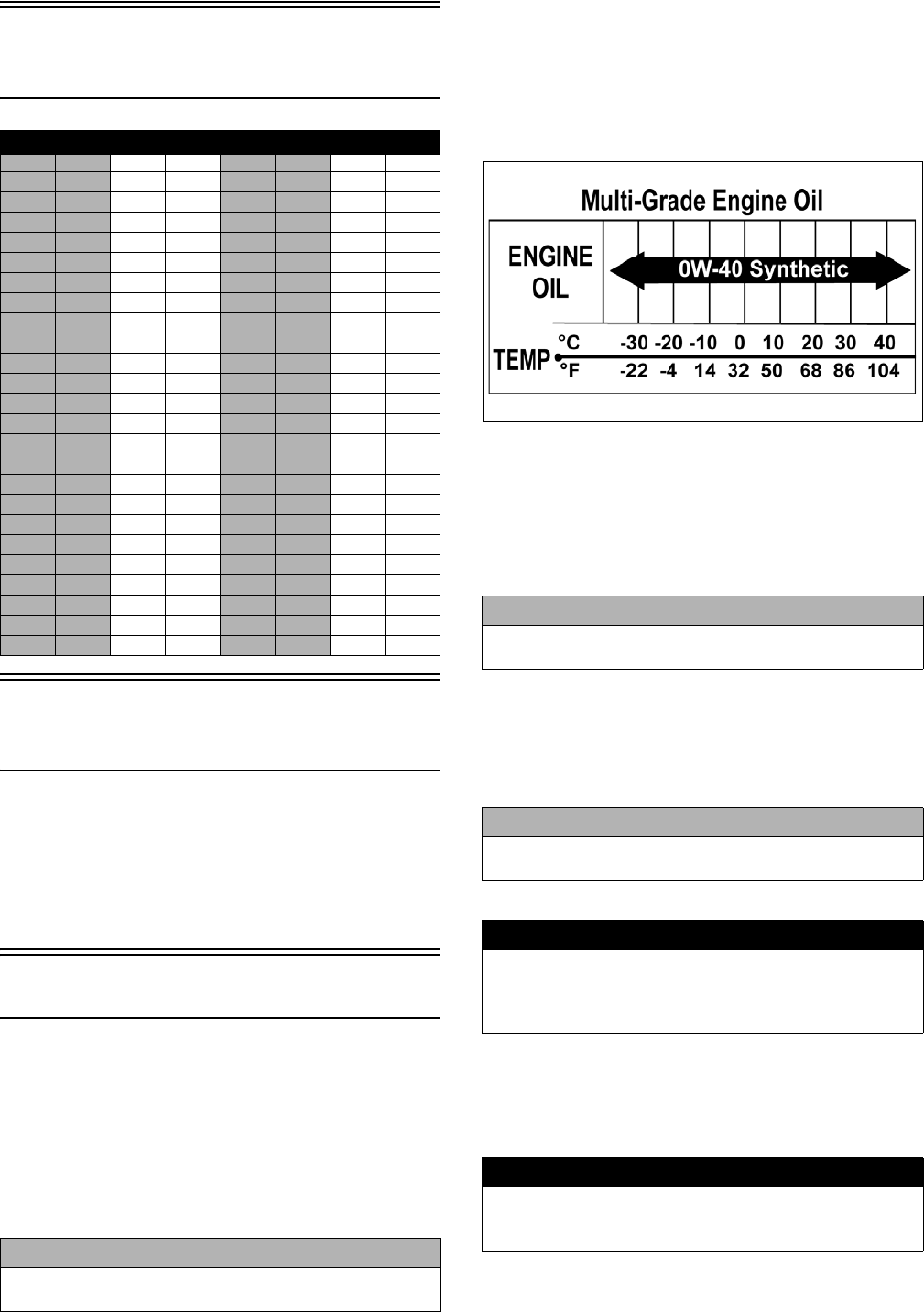
RECOMMENDED ENGINE OIL
The recommended oil to use is Arctic Cat ACX All
Weather synthetic engine oil, which has been specifically
formulated for use in this Arctic Cat engine. Although
Arctic Cat ACX All Weather synthetic engine oil is the
only oil recommended for use in this engine, use of any
API certified SM 0W-40 oil is acceptable.
OILCHARTJ
RECOMMENDED FRONT
DIFFERENTIAL LUBRICANT
The recommended lubricant is Arctic Cat Gear Lube or an
equivalent gear lube which is SAE approved 80W-90 hypoid.
This lubricant meets all of the lubrication requirements of the
Arctic Cat vehicle front differential and rear drive.
RECOMMENDED TRANSAXLE
LUBRICANT
The recommended transaxle lubricant is Arctic Cat Syn-
thetic Transaxle Fluid. This lubricant meets all of the lubri-
cation requirements of this vehicle.
FILLING GAS TANK
Since gasoline expands as its temperature rises, the gas
tank must be filled to its specified capacity only. Expan-
sion room must be maintained in the tank particularly if
the tank is filled with cold gasoline and then moved to a
warm area.
ft-lb N-m ft-lb N-m ft-lb N-m ft-lb N-m
11.4 26 35.4 51 69.4 76 103.4
22.7 27 36.7 52 70.7 77 104.7
34.1 28 38.1 53 72.1 78 106.1
45.4 29 39.4 54 73.4 79 107.4
56.8 30 40.8 55 74.8 80 108.8
68.2 31 42.2 56 76.2 81 110.2
79.5 32 43.5 57 77.5 82 111.5
810.9 33 44.9 58 78.9 83 112.9
912.2 34 46.2 59 80.2 84 114.2
10 13.6 35 47.6 60 81.6 85 115.6
11 15 36 49 61 83 86 117
12 16.3 37 50.3 62 84.3 87 118.3
13 17.7 38 51.7 63 85.7 88 119.7
14 19 39 53 64 87 89 121
15 20.4 40 54.4 65 88.4 90 122.4
16 21.8 41 55.8 66 89.8 91 123.8
17 23.1 42 57.1 67 91.1 92 125.1
18 24.5 43 58.5 68 92.5 93 126.5
19 25.8 44 59.8 69 93.8 94 127.8
20 27.2 45 61.2 70 95.2 95 129.2
21 28.6 46 62.6 71 96.6 96 130.6
22 29.9 47 63.9 72 97.9 97 131.9
23 31.3 48 65.3 73 99.3 98 133.3
24 32.6 49 66.6 74 100.6 99 134.6
25 34 50 68 75 102 100 136
CAUTION
Do not use white gas. Only Arctic Cat approved gaso-
line additives should be used.
CAUTION
Any lubricant used in place of the recommended lubri-
cant could cause serious front differential damage.
CAUTION
Any lubricant used in place of the recommended lubri-
cant could cause serious transaxle damage.
! WARNING
Always fill the gas tank in a well-ventilated area. Never
add fuel to the gas tank near any open flames or with
the engine running. DO NOT SMOKE while filling the
gas tank.
! WARNING
Do not overflow gasoline when filling the gas tank. A
fire hazard could materialize. Always allow the engine to
cool before filling the gas tank.

5
Tighten the gas tank cap securely after filling the tank.
Genuine Parts
When replacement of parts is necessary, use only genuine Arc-
tic Cat parts. They are precision-made to ensure high quality
and correct fit. Refer to the appropriate Illustrated Parts Man-
ual for the correct part number, quantity, and description.
Preparation For Storage
1. Clean the seat cushion (cover and base) with a damp
cloth and allow it to dry.
2. Clean the vehicle thoroughly by washing dirt, oil,
grass, and other foreign matter from the entire vehicle.
Allow it to dry thoroughly. DO NOT get water into
any part of the engine or air intake.
3. Either drain the gas tank or add Fuel Stabilizer to the
gas in the gas tank. Remove the air filter housing
cover and air filter. Start the engine and allow it to
idle. Using Arctic Cat Engine Storage Preserver, rap-
idly inject the preserver into the air filter opening for a
period of 10 to 20 seconds; then stop the engine.
Install the air filter and housing cover.
4. Plug the exhaust hole in the exhaust system with a
clean cloth.
5. Apply light oil to the plungers of the shock absorbers.
6. Tighten all nuts, bolts, cap screws, and screws. Make
sure rivets holding components together are tight.
Replace all loose rivets. Care must be taken that all
calibrated nuts, cap screws, and bolts are tightened to
specifications.
7. Fill the cooling system to the bottom of the stand pipe
in the radiator neck with properly mixed coolant.
8. Disconnect the battery cables; then remove the bat-
tery, clean the battery posts and cables, and store in a
clean, dry area.
9. Store the vehicle indoors in a level position.
Preparation After
Storage
Taking the vehicle out of storage and correctly preparing it
will assure many miles and hours of trouble-free riding.
1. Clean the vehicle thoroughly.
2. Clean the engine. Remove the cloth from the exhaust
system.
3. Check all control wires and cables for signs of wear or
fraying. Replace if necessary.
4. Change the engine oil and filter.
5. Check the coolant level and add properly mixed cool-
ant as necessary.
6. Charge the battery; then install. Connect the battery
cables.
7. Check the entire brake systems (fluid level, pads,
etc.), all controls, headlights, taillight, brakelight, and
headlight aim; adjust or replace as necessary.
8. Tighten all nuts, bolts, cap screws, and screws making
sure all calibrated nuts, cap screws, and bolts are tight-
ened to specifications.
9. Check tire pressure. Inflate to recommended pressure
as necessary.
10. Make sure the steering moves freely and does not
bind.
11. Check the spark plugs. Clean or replace as necessary.
! WARNING
Do not over-fill the gas tank.
CAUTION
Prior to storing the vehicle, it must be properly serviced
to prevent rusting and component deterioration.
CAUTION
If the interior of the air filter housing is dirty, clean the
area before starting the engine.
CAUTION
Avoid storing outside in direct sunlight and avoid using
a plastic cover as moisture will collect on the vehicle
causing rusting.
CAUTION
The ignition switch must be in the OFF position prior to
installing the battery or damage may occur to the igni-
tion system.
CAUTION
Connect the positive battery cable first; then the nega-
tive.

6
Periodic Maintenance/
Tune-Up
This section has been organized into sub-sections showing
common maintenance procedures.
SPECIAL TOOLS
A number of special tools must be available to the techni-
cian when performing service procedures in this section.
Refer to the current Special Tools Catalog for the appropri-
ate tool description.
NOTE: Special tools are available from the Arctic
Cat Service Department.
Periodic Maintenance
Chart
A = Adjust I = Inspect C = Clean L = Lubricate R = Replace T = Tighten
* Service/Inspect more frequently when operating in adverse conditions.
** When using an API certified SM 0W-40 oil.
*** When using Arctic Cat ACX All Weather synthetic oil, oil change and strainer inspection interval can be increased to every
1,000 miles or every year.
Description p/n
Compression Tester Kit 0444-213
Oil Filter Wrench 0644-389
Timing Light 0644-296
Item Initial Service After
Break-In (First
Month or 100 Miles) Daily Monthly
(100 Miles)
Every 3
Months (300
Miles)
Every 6
Months (500
Miles)
Annually
(1500 Miles) As
Needed
Battery II C
Fuses IR
Air Filter II* R
Valve/Tappet Clearance IIA
Engine Compression I
Spark Plugs I I I R (4000 Mi
or 18 Mo)
Muffler/Spark Arrester CR
Gas Hoses II R (2 Yrs)
Throttle Cable Ends/Accelerator Pedal Pivot II C-L A-R
Engine Oil/Filter R R*/R**/R*** A/R
Front Differential Lubricant RI R
Transaxle Lubricant RI R
(2000Mi)
Tires/Air Pressure II R
Steering Components II I R
V-Belt IlR
Suspension (Ball joint boots, drive axle boots
front and rear, tie rods, differential and rear
drive bellows)
II R
Nuts/Bolts/Cap Screws TT A
Ignition Timing I
Headlight/Taillight-Brakelight II R
Switches II R
Shift Lever IA-L
Gauge/Indicators II R
Frame/Welds II l
Electrical Connections lC
Complete Brake System II
Brake Pads II* R
Brake Fluid II R (2 Yrs)
Brake Hoses II R (4 Yrs)
Coolant/Cooling System II R (2 Yrs)
Wheel Lug Nuts TT
7
Lubrication Points
It is advisable to lubricate certain components periodically
to ensure free movement. Apply light oil to the compo-
nents using the following list as reference.
A. Accelerator Pedal Pivot/Cable Ends
B. Brake Pedal Pivot
C. Shift Cable
Air Filter
CLEANING AND INSPECTING FILTER
1. Unsnap the five fasteners securing the air filter hous-
ing cover and remove the cover.
WT006A
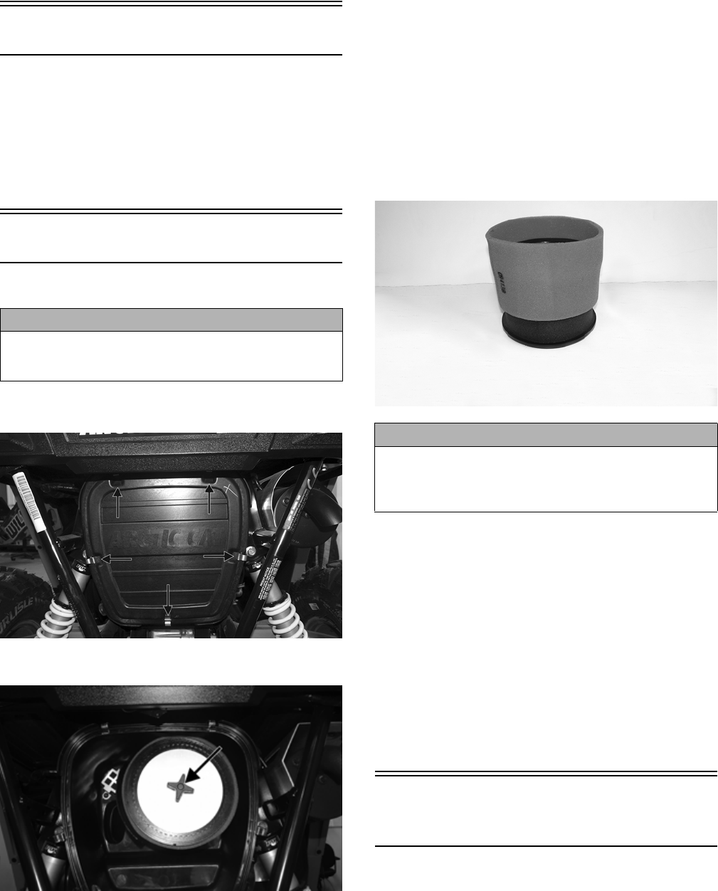
2. Remove the air filter knob; then remove the air filter.
WT176A
NOTE: Do not attempt to remove the inner foam
from the wire mesh. It is part of the filter frame.
3. Fill a wash pan larger than the filter with a non-flam-
mable cleaning solvent; then dip the inner filter and
outer foam medium in the solvent and wash them.
NOTE: Foam Filter Cleaner and Foam Filter Oil are
available from Arctic Cat.
4. Dry both filter components.
5. Put the foam filter in a plastic bag; then pour in air fil-
ter oil and work the filter.
NOTE: Apply oil to the inner filter; then carefully
squeeze excessive oil from the filter element. Do not
twist foam to remove oil.
6. Attach the foam filter to the inner filter screen.
WT179
7. Clean any dirt or debris from inside the air cleaner. Be
sure no dirt enters the throttle body.
8. Place the foam filter onto the filter frame; then install
the air filter on the filter rod and install the filter knob.
Tighten securely.
9. Install the air filter housing cover and secure with the
retaining clips.
CHECKING AND CLEANING DRAINS
1. Inspect the drain beneath the main housing for debris
or liquid. Remove and clean the drain bulb if contami-
nated.
2. Wipe any accumulation of oil or gas from the filter
housing and drain.
Testing Engine
Compression
NOTE: The engine should be warm (operating tem-
perature) and the battery fully charged for an accurate
compression test.
NOTE: The access panel must be removed for this
procedure.
CAUTION
Failure to inspect the air filter frequently if the vehicle is
used in dusty, wet, or muddy conditions can damage
the engine.
CAUTION
A torn air filter can cause damage to the vehicle engine. Dirt
and dust may get inside the engine if the element is torn.
Carefully examine the element for tears before and after
cleaning it. Replace the element with a new one if it is torn.
8
WT021
1. Remove the spark plug wires from the spark plugs.
2. Using compressed air, blow any debris from around
the spark plugs.
3. Remove the spark plugs; then attach the spark plug wires
to the plugs and ground the plugs on the cylinder heads
well away from the spark plug holes.
4. Attach the Compression Tester Kit.
5. While holding the throttle in the full-open position, crank
the engine over with the electric starter until the gauge
stops climbing (five to 10 compression strokes). Compres-
sion should be as shown in the chart.
6. If compression is abnormally low, verify the following:
A. Starter cranks engine over (normal speed).
B. Gauge is functioning properly.
C. Throttle in the full-open position.
D. Valve/tappet clearance correct.
E. Engine warmed up.
7. If compression is still low, check for blown cylinder head
gasket, valve leakage, or worn piston rings or cylinder
(see Engine – Servicing Top-Side Components).
Spark Plugs
A light brown insulator indicates the plug is correct. A white or
dark insulator indicates that the engine may need to be ser-
viced. To maintain a hot, strong spark, keep the plug free of
carbon. Adjust the gap to 0.6-0.8 mm (0.023-0.031 in.).
ATV-0051
ATV-0052
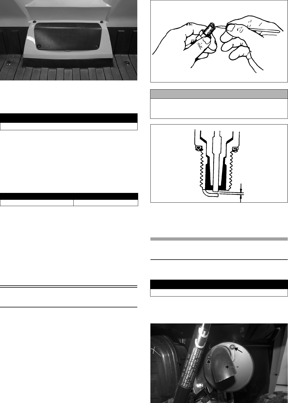
When installing a spark plug, be sure to tighten it securely. A
new spark plug should be tightened 1/2 turn once the washer
contacts the cylinder head. A used spark plug should be tight-
ened 1/8-1/4 turn once the washer contacts the cylinder head.
Muffler/Spark Arrester
Clean the spark arrester using the following procedure.
1. Remove the spark arrester screen; then using a suit-
able brush, clean the carbon deposits from the screen
taking care not to damage the screen.
WT005A
! WARNING
Always wear safety glasses when using compressed air.
PSI (WOT)
Cylinder #1/Cylinder #2 185
CAUTION
Before removing a spark plug, be sure to clean the area
around the spark plug. Dirt could enter engine when
removing or installing the spark plug.
! WARNING
Wait until the muffler cools to avoid burns.
9
NOTE: If the screen or gasket is damaged in any
way, it must be replaced.
2. Install the spark arrester assembly and gasket and
secure with the cap screws. Tighten the cap screws to
72 in.-lb.
Engine Oil - Filter
OIL - FILTER
Change the engine oil and oil filter at the scheduled inter-
vals. The engine should always be warm when the oil is
changed so the oil will drain easily and completely.
1. Park the vehicle on level ground; then remove the
access panel.
WT037A
2. Remove the oil level stick/filler plug.
WT035A
3. Remove the drain plug from the bottom of the engine
and drain the oil into a drain pan.
WT294A
4. Using the Oil Filter Wrench and a ratchet handle (or a
socket or box-end wrench), remove the old oil filter.
NOTE: Clean up any excess oil after removing the filter.
5. Apply oil to a new filter O-ring and check to make
sure it is positioned correctly; then install the new oil
filter. Tighten securely.
6. Install the engine drain plug and tighten to 16 ft-lb.
Pour the specified amount of the recommended oil in
the filler hole. Install the oil level stick/filler plug.
7. Start the engine (while the vehicle is outside on level
ground) and allow it to idle for a few minutes.
8. Turn the engine off and wait approximately one minute.
9. Unscrew the oil level stick and wipe it with a clean
cloth.
10. Install the oil level stick and thread into the engine
case.
NOTE: The oil level stick should be threaded into
the case for checking the oil level.
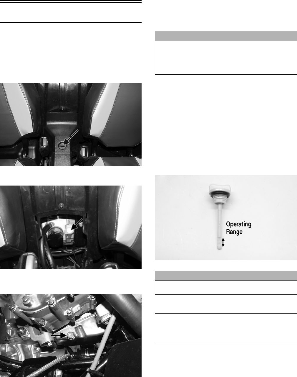
11. Remove the oil level stick; the oil level must be within
the operating range but not exceeding the upper mark.
WT066A
12. Inspect the area around the drain plug and oil filter for
leaks.
Front Differential -
Transaxle Lubricant
To check front differential lubricant, use the following pro-
cedure.
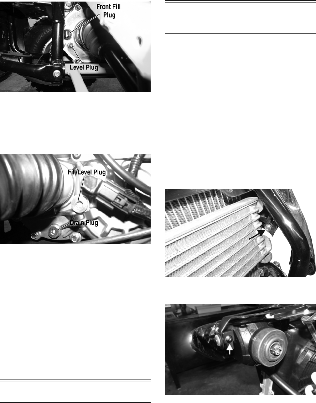
1. Remove the level plug; lubricant should be level with
the bottom threads.
CAUTION
Any oil used in place of the recommended oil could cause
serious engine damage. Do not use oils which contain
graphite or molybdenum additives. These oils can
adversely affect clutch operation. Also, not recommended
are racing, vegetable, non-detergent, and castor-based oils.
CAUTION
Do not over-fill the engine with oil. Always make sure
that the oil level is not above the upper mark.
10
WT041A
2. If low, remove the fill plug and add lubricant until it
appears at the level plug threads. Tighten the fill plug
to 16 ft-lb and the level plug to 45 in.-lb.
To check transaxle lubricant, use the following procedure.
1. Remove the fill/level plug; the lubricant level should
be level with the bottom of the plug threads.
WT025A
2. If low, add Arctic Cat Transaxle Fluid as necessary.
Tighten the fill/level plug to 16 ft-lb.
To change the lubricant, use the following procedure.
1. Place the vehicle on level ground.
2. Remove each drain and fill plug.
3. Drain the lubricant into a drain pan.
4. After all the lubricant has been drained, install the
drain plug and tighten to 16 ft-lb.
5. Pour the appropriate amount of recommended lubri-
cant into the fill hole.
6. Install the fill plug and tighten to 16 ft-lb.
NOTE: If the lubricant is contaminated with water,
inspect the drain plug, fill plug, and/or bladder.
Nuts/Bolts/Cap Screws
Tighten all nuts, bolts, and cap screws. Make sure rivets
holding components together are tight. Replace all loose
rivets. Care must be taken that all calibrated nuts, bolts,
and cap screws are tightened to specifications.
Headlight/Taillight-
Brakelight
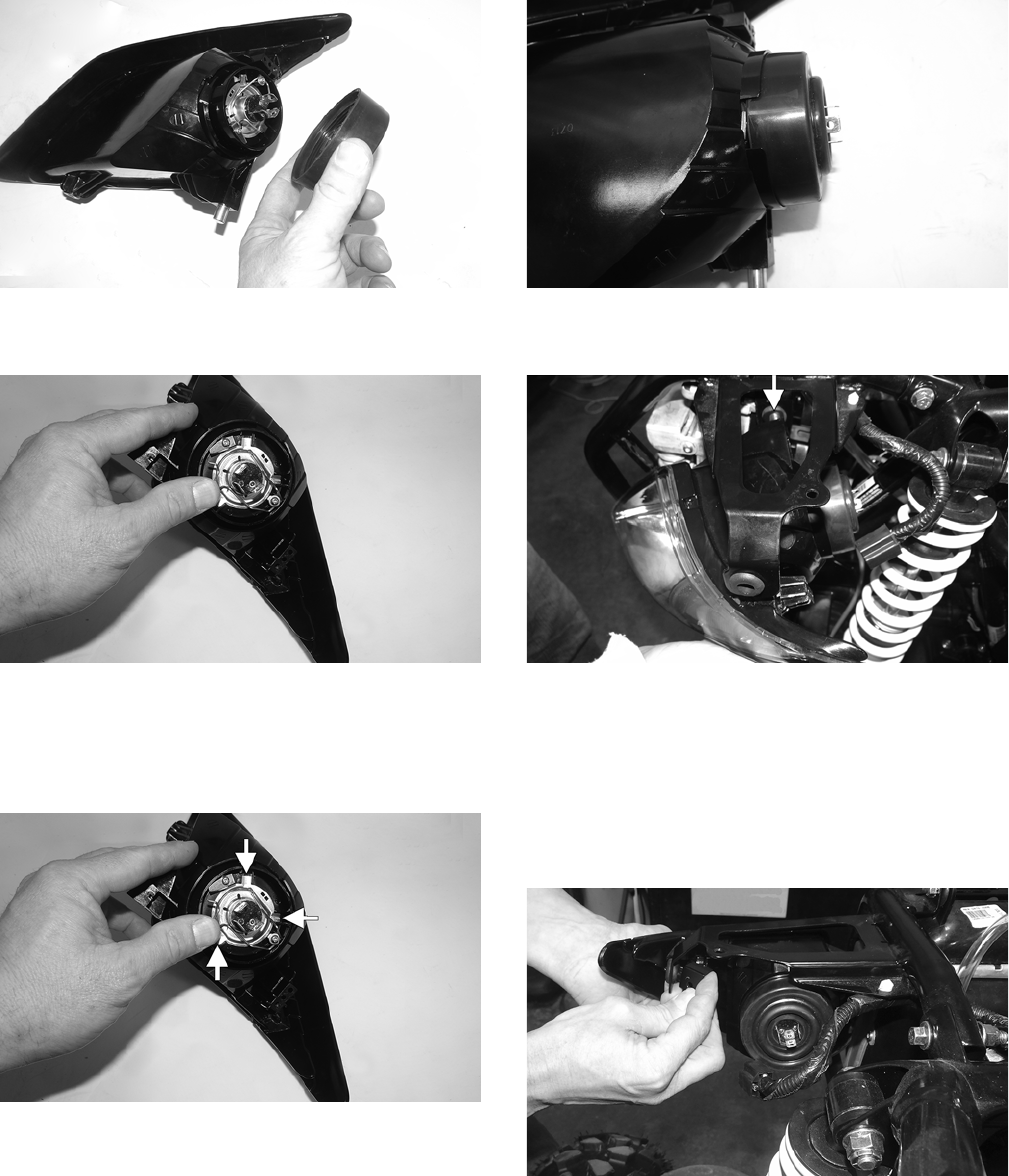
HEADLIGHT BULB REPLACEMENT
1. Remove the wiring harness connector from the back
of the headlight.
2. Remove the rubber seal; then release the retaining
clip. Remove the bulb.
3. Install the new bulb; then attach the retaining clip and
press on the rubber boot.
4. Connect the wiring harness.
5. Adjust the headlight using the Checking/Adjusting
Headlight Aim instructions in this sub-section.
REMOVING HEADLIGHT ASSEMBLY
1. Remove the grille.
NOTE: Removing the front fender will aid in replac-
ing the headlight assembly.
2. Remove the headlight adjustment cap screw.
WT065A
3. Remove the inner cap screw securing the rear of the
headlight assembly.
WT272
4. Push the headlight assembly inward towards the radia-
tor and lift slightly on the exterior bracket until the
mounting stud is free; then remove the headlight
assembly.
5. Remove the rubber seal at the rear of the headlight
assembly.
11
WT263
6. Release the spring clip securing the headlight bulb;
then remove the bulb.
WT264
INSTALLING HEADLIGHT ASSEMBLY
1. Install the headlight bulb making sure each tab is posi-
tioned correctly and that it cannot rotate clockwise.
Secure the bulb with the spring.
WT264A
2. Install the rubber seal so that it is fully seated.
WT262
3. Starting with the interior mounting stud, install the
headlight assembly into position.
WT269A
NOTE: Applying lubricant to the studs will aid in
assembly.
4. With the interior stud in place in the grommet, work
the exterior stud into position.
NOTE: It may be necessary to lightly pull on the
exterior bracket to insert the exterior mounting stud.
WT270
5. Secure the headlight with the existing screws.
6. Connect the wiring harness and install the front
fender; then install the grille.
7. Check and adjust headlight aim (see Periodic Mainte-
nance section).
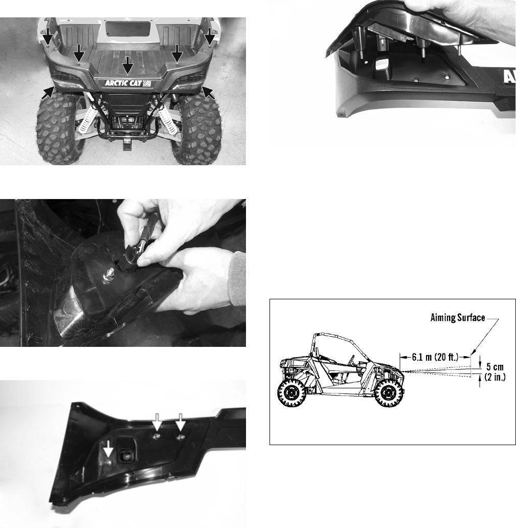
REMOVING TAILLIGHT/BRAKELIGHT
NOTE: The LED taillights are not replaceable. The
entire assembly must be replaced as a component.
12
1. Remove the fasteners securing the facia to the storage box.
WT101A
2. Disconnect the wiring harness.
WT222
3. Remove the lock nuts securing the taillight to the facia.
WT259A
INSTALLING TAILLIGHT/
BRAKELIGHT
1. Install the new taillight into the facia using new lock
nuts. Tighten to 36 in.-lb.
WT260
2. Connect the wiring harness and secure the facia using
the existing fasteners. Tighten securely.
CHECKING/ADJUSTING HEADLIGHT
AIM
The headlights can be adjusted vertically. The geometric
center of the HIGH beam light zone is to be used for verti-
cal aiming.
1. Position the vehicle on a level floor so the headlights
are approximately 6.1 m (20 ft) from an aiming sur-
face (wall or similar aiming surface).
0748-285
NOTE: There should be an average operating load
on the vehicle when adjusting the headlight aim.
2. Measure the distance from the floor to the mid-point
of each headlight.
3. Using the measurements obtained in step 2, make hor-
izontal marks on the aiming surface.
4. Switch on the lights. Make sure the HIGH beam is on.
DO NOT USE LOW BEAM.
5. Observe each headlight beam aim. Proper aim is when
the most intense beam is 5 cm (2 in.) below the hori-
zontal mark on the aiming surface.
6. Remove the front grille; then loosen the cap screw and
move the headlight assembly up or down as required.
Tighten to 60 in.-lb.
13
WT065A
Hydraulic Brake System
CHECKING/BLEEDING
The hydraulic brake system has been filled and bled at the
factory. To check and/or bleed a hydraulic brake system,
use the following procedure.
1. With the vehicle in a level position and the tires prop-
erly inflated, check the fluid level in the reservoir. If
the level in the reservoir is not above the MIN, add
DOT 4 brake fluid.
WT012A
2. Depress the brake pedal several times to check for a firm
brake. If the brake is not firm, the system must be bled.
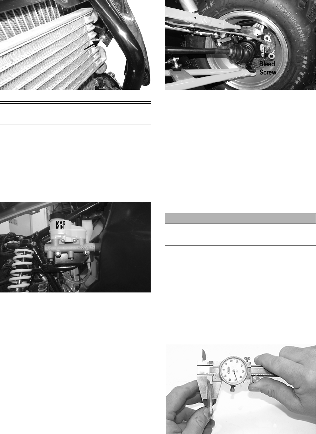
3. To bleed the brake system, use the following procedure:
A. Remove the cover and fill the reservoir with DOT
4 brake fluid.
B. Install and secure the cover; then slowly press the
brake pedal several times.
C. Install one end of a clear hose onto the bleed screw
farthest from the cylinder (right rear) and direct the
other end into a container; then while holding
slight pressure on the brake pedal, open the bleed
screw and watch for air bubbles. Close the bleed
screw before releasing the brake pedal. Repeat this
procedure until no air bubbles are present.
WT045A
NOTE: During the bleeding procedure, watch the
reservoir very closely to make sure there is always a
sufficient amount of brake fluid. If the fluid level gets
low in the reservoir, refill the reservoir before the
bleeding procedure is continued.
D. Repeat step C until the brake pedal is firm.
E. At this point, perform step B, C, and D on the left
rear bleed screw; then move to the right front bleed
screw and follow the same procedure. Finish with
the left front bleed screw.
4. Carefully check the entire hydraulic brake system
that all hose connections are tight, the bleed screws
are tight, the protective caps are installed, and no
leakage is present.
INSPECTING HOSES
Carefully inspect the hydraulic brake hoses for cracks or
other damage. If found, the brake hoses must be replaced.
CHECKING/REPLACING PADS
The clearance between the brake pads and brake discs is
adjusted automatically as the brake pads wear. The only
maintenance that is required is replacement of the brake
pads when they show excessive wear. Check the thickness
of each of the brake pads as follows.
1. Remove a front wheel.
2. Measure the thickness of each brake pad.
WT220
CAUTION
This hydraulic brake system is designed to use DOT 4
brake fluid only. If brake fluid must be added, care must be
taken as brake fluid is very corrosive to painted surfaces.
14
3. If thickness of either brake pad is less than 1.0 mm
(0.039 in.), the brake pads must be replaced.
NOTE: The brake pads should be replaced as a set.
4. To replace the brake pads, use the following procedure.
A. Remove the cap screws securing the caliper holder to
the knuckle; then remove the pads from the caliper.
WT221
B. Install the new brake pads.
C. Secure the caliper holder to the knuckle with new
“patch-lock” cap screws. Tighten to 20 ft-lb.
WT287A
5. Install the wheel; then using a crisscross pattern, tighten
the wheel nuts in 20 ft-lb increments to a final torque of 40
ft-lb (steel wheel) or 80 ft-lb (aluminium wheel).
6. Burnish the brake pads (see Burnishing Brake Pads in this
section).
BRAKE DISC
Using a micrometer, measure the thickness of the brake disc in
the contact surface. If thickness is 0.125-in. or less, the disc must
be replaced. To replace the brake disc, see Drive System – Hub.
Burnishing Brake Pads
Brake pads must be burnished to achieve full braking effective-
ness. Braking distance will be extended until brake pads are
properly burnished. To properly burnish the brake pads, use the
following procedure.
1. Choose an area large enough to safely accelerate the vehi-
cle to 30 mph and to brake to a stop.
2. Accelerate to 30 mph; then depress the brake pedal to
decelerate to 0-5 mph.
3. Repeat procedure 20 times until brake pads are burnished.
Replacing V-Belt
NOTE: If a clutch or any clutch component has been
replaced or the technician is unsure of shim quantity/
placement, clutch offset must be verified (see Engine
- Servicing Left-Side Components).
NOTE: Drive belts require a break-in period (see Break-in
Procedure - Drive Belt in the General Information Section).
REMOVING
1. Raise the rear of the vehicle just enough to unload the rear
suspension (weight off the shock absorbers).
2. Remove the left rear tire.
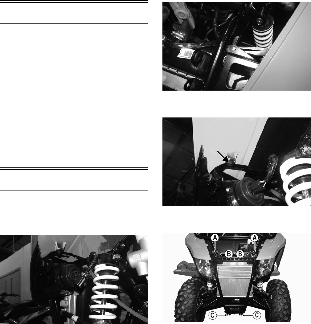
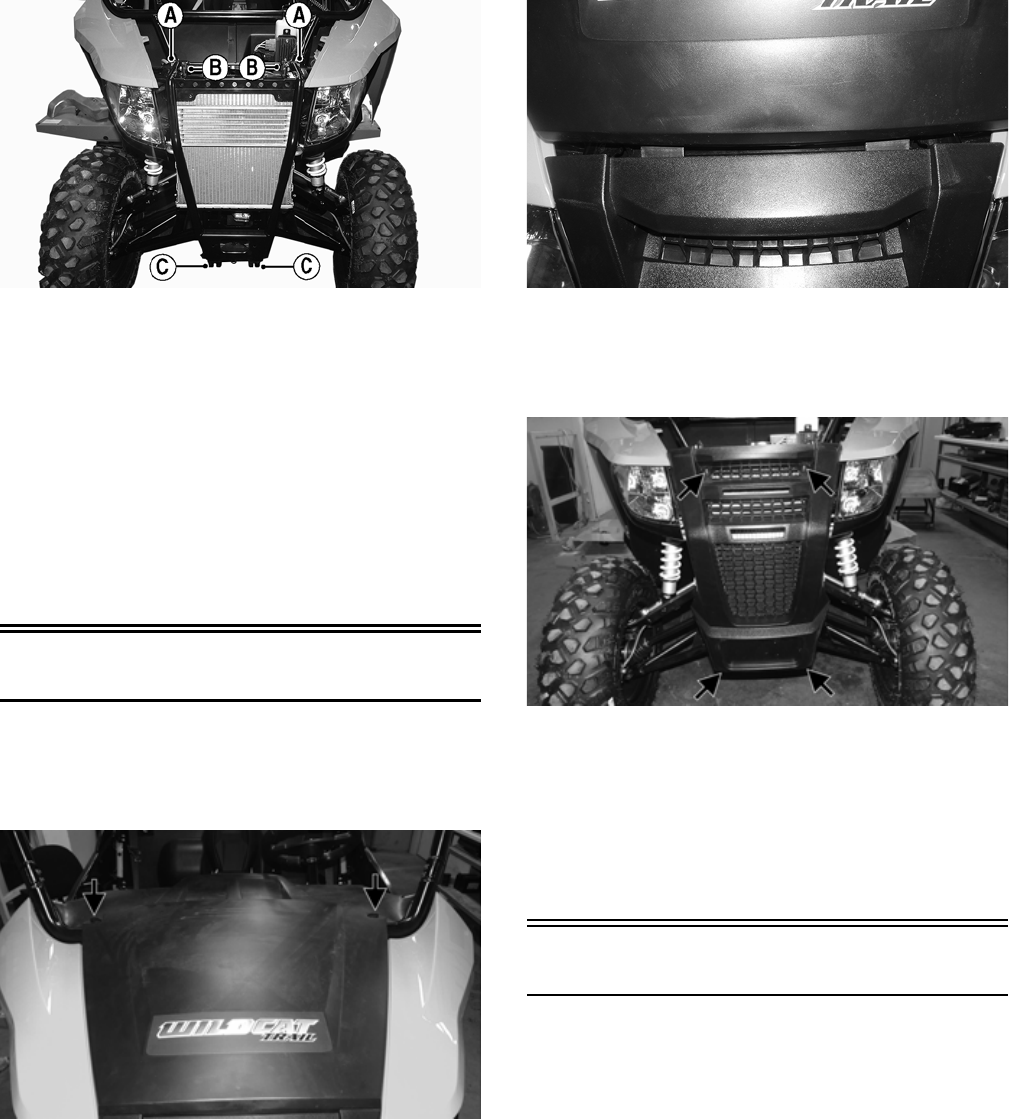
3. Remove the cap screws securing the outer clutch cover;
then remove the outer clutch cover.
WT182A
4. Remove the cap screw securing the driven clutch to
the output shaft. Account for the washer.
! WARNING
Failure to properly burnish the brake pads could lead to
premature brake pad wear or brake loss. Brake loss can
result in severe injury.
CAUTION
Failure to properly break-in a new drive belt will result in
premature belt failure.
15
WT183A
5. Remove the stationary sheave and V-belt and any belt
threads or debris in the clutch housing or sheaves.
NOTE: If removing the stationary sheave, account
for the alignment shims in the moveable sheave (see
Servicing Left-Side Components in the Engine sec-
tion for proper shimming).
WT186A
INSTALLING
1. Making sure the directional arrows on the belt are aligned
with engine rotation, place the drive belt on the drive
clutch; then making sure the “X” marks are aligned, install
the alignment shims (if applicable) and stationary sheave
on the driven clutch.
WT517A
WT200A
2. Using an appropriate strap or oil filter wrench (3 5/8”)
to hold the driven clutch and ensuring the splines of the
sheave and input shaft are engaged, secure the clutch
with the cap screw and washer. Tighten to 35 ft-lb.
WT202
3. Install the clutch cover and secure with the cap screws.
Tighten to 50 in.-lb.
WT182A
4. Install the left rear tire. Tighten in a crisscross pattern
in 20 ft-lb increments to 40 ft-lb (steel wheel) or 80 ft-
lb (aluminum wheel).
16
Steering/Frame/Controls
The following steering components should be inspected
periodically to ensure safe and proper operation.
A. Steering wheel secure.
B. Steering has equal and complete full-left and full-
right capability.
C. Steering sector mounting bolts tight.
D. Ball joints not worn, cracked, or damaged.
E. Tie rods not bent or cracked.
F. Knuckles not worn, cracked, or damaged.
G. Cotter pins not damaged or missing.
H. Steering wheel tilt locks securely.
The frame and welds should be checked periodically for
damage, bends, cracks, deterioration, broken components,
and missing components.
Front Bumper
REMOVING
1. Remove the hood and grille (see Hood and Grille). \
2. Disconnect the headlights.
WT463
3. Using a suitable prying tool, pry the clips out from
between the wiring harness and the frame. Press the
clips downward to remove from frame.
WT454
4. Remove the cap screws from both sides securing the
front fenders to the frame.
WT453A
5. Remove the cap screws (A, B, and C) and discard the
lock nuts from (A). Remove the bumper.
WT548A
INSTALLING
1. Place the bumper frame into position place and with
the existing cap screws and new lock nuts (A), finger-
tighten at this point.
17
WT548A
2. Install the lower bumper cap screws (C); then tighten
the upper and lower bumper cap screws to 20 ft-lb.
3. Install the cap screws and nuts securing the radiator to
the frame (B). Tighten to 8 ft-lb.
4. Install the cap screws securing the front fenders to the
frame; then tighten securely.
5. Connect the headlights.
6. Using the existing cap screws, secure the grille and
tighten securely.
7. Install the hood and secure with the quarter-turn fas-
teners
Hood and Grille
REMOVING/INSTALLING HOOD
1. Turn the two quarter-turn fasteners counterclockwise
and remove hood.
WT226A
2. Insert the hood tabs into the grille and lay the hood
down flat. Turn both of the fasteners clockwise secur-
ing the hood.
WT251
REMOVING GRILLE
Remove the fasteners securing the grille; then remove the
grille.
WT256A
CLEANING AND INSPECTION GRILLE
Clean any dirt or debris from the grille webbing. This
helps air flow to the radiator and oil cooler.
INSTALLING GRILLE
Place the grille into position and secure it using the exist-
ing cap screws. Tighten all hardware to 60 in.-lb.
Body Panels
REMOVING REAR BODY PANELS
1. Remove the seats.
2. Remove the push pins and cap screws securing the
rear fenders.
18
WT209A
3. Remove the cap screws securing the taillight/brake-
light assembly to the frame and disconnect the har-
ness.
WT101A
WT222
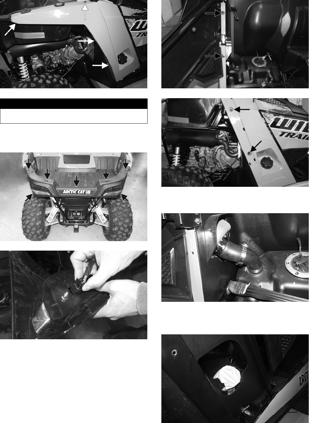
4. Remove the fasteners securing the right rear body
panel.
WT241A
WT227A
5. Loosen the gas tank filler hose clamp and slide it
down towards the tank.
WT244
6. Remove the panel from the frame while also pulling
on the filler hose. Seal off the hose to prevent objects
from entering the hose.
WT246
7. Remove the air pre-filter cover.
! WARNING
The heat deflector under the right-rear fender has sharp
edges and can cause serious injury if care is not taken.
19
WT028A
8. Loosen the clamp securing the clutch air intake tube to
engine; then pry the tube off of engine. Account for
the clamp.
WT487A
9. Remove the fasteners securing the left rear body panel.
WT250A
10. Remove the panel with the air/clutch intake tubes.
WT486
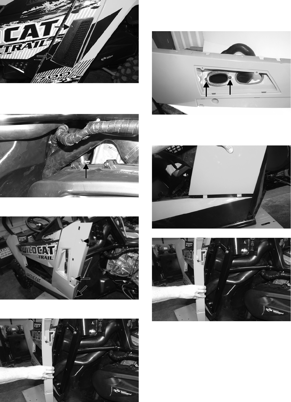
INSTALLING REAR BODY PANELS
1. If removed, install the clutch air intake tube through
the left rear body opening and secure it with the plate
and existing cap screws. Tighten securely.
WT484A
2. Install the tabs of the body panel into the slots in the
side panel; then route the air intake clutch tube to the
engine.
WT490
WT486
3. With the panel tabs in place, press the panel towards
the frame and maneuver the air intake tube inside the
boot.
20
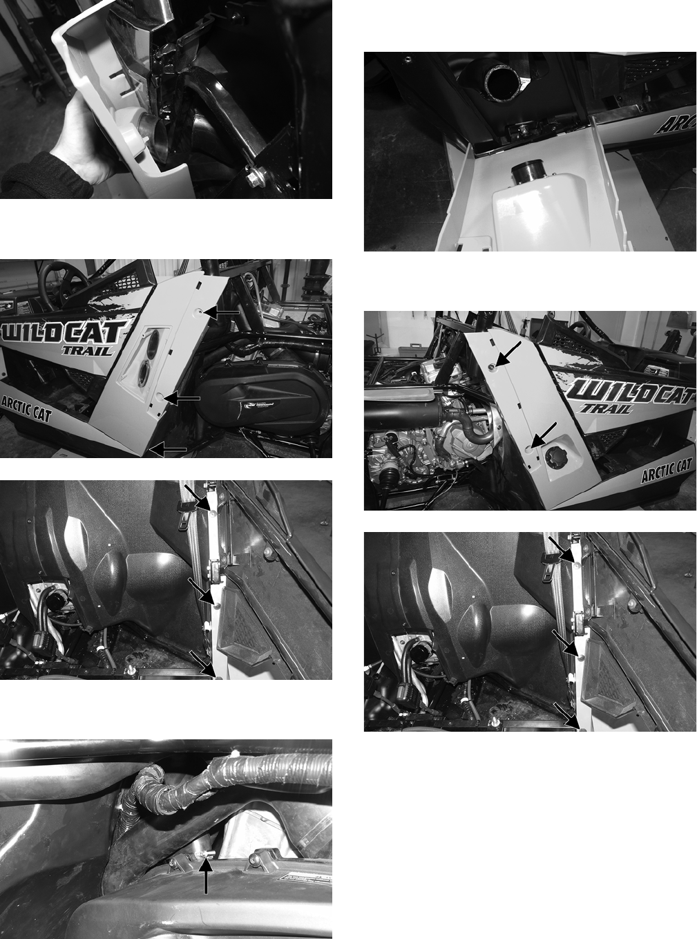
WT485
4. Secure the panel to the frame and pre-filter cover with
the existing cap screws and push pins.
WT488A
WT489A
5. Install the clutch intake tube onto the engine and
secure it with the clamp. Tighten securely.
WT487A
6. Install the left rear fender and secure it with the exist-
ing hardware.
7. Install the tabs of the body panel into the slots in side
panel; then insert the plastic insert into the gas tank
filler hose. Tighten the clamp and install the gas cap.
WT245
8. Secure the panel to the frame with the existing cap
screws and push pins.
WT491A
WT489A
9. Install the right rear fender and secure with the exist-
ing hardware; then install the seats.
21
WT209A
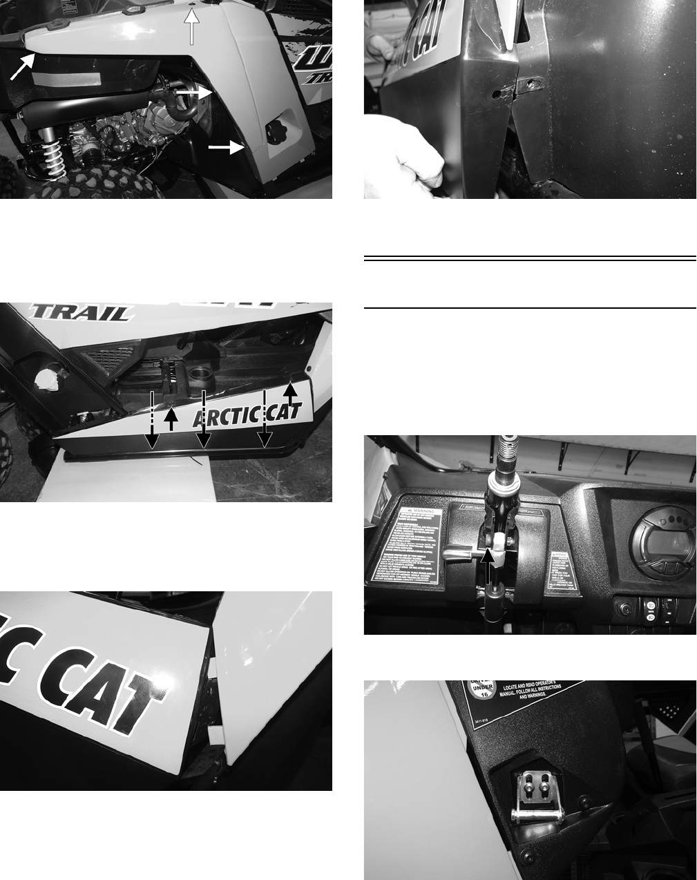
REMOVING SIDE PANELS
To remove a side panel, remove the cap screws and push
pins securing the side panel to the frame; then remove the
panel.
WT257A
INSTALLING SIDE PANELS
1. To install a side panel, install the side panel tabs into
the front upper side panel slots.
WT211
NOTE: Make sure the bottom of the side panel is on
the outside of the inner splash panel.
WT212
2. Secure the side panel using the existing cap screws
and push pins. Tighten all hardware to 60 in.-lb.
Dash/Switches
REMOVING
1. Remove the steering wheel (see Steering Wheel in this
section).
2. Remove the top steering tilt assembly cap screw and
discard the nut.
WT338A
3. Remove the door latches and discard the cap screws.
WT010
4. Remove the fasteners and push pins securing the dash
to the frame.
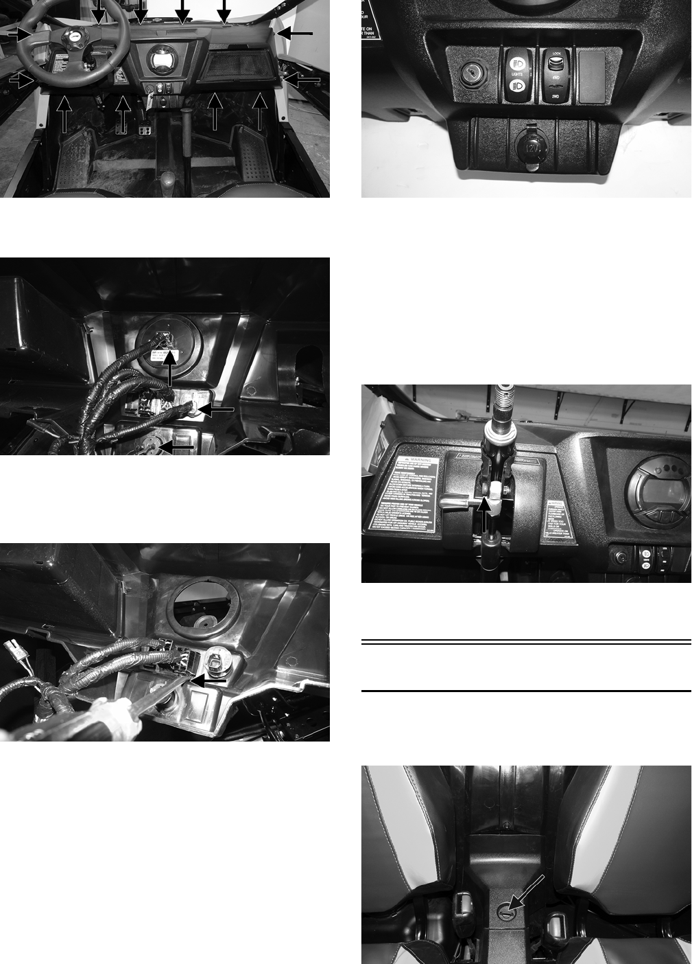
22
WT014A
5. Disconnect the LCD gauge, ignition switch, and 12-
volt accessory plug.
WT336A
6. Using an appropriate tool, push the bottom dash tabs
in; then push the top tabs in and press the rocker
switches through the dash. Disconnect the rocker
switches and remove the dash.
WT337A
INSTALLING
1. Install the switches into the appropriate locations.
Push the switches into the dash until they snap into
place.
WT341
2. Connect the 12-volt accessory plug, ignition switch,
and LCD gauge.
3. With the steering shaft slid through the dash, install
the dash and secure it with the existing fasteners.
4. Using new “patch-lock” cap screws, install the door
latches. Adjust the doors (see Doors in this section);
then tighten to 8 ft-lb.
5. Using a new lock nut, install the tilt assembly and
tighten to 10 ft-lb.
WT338A
6. Install the steering wheel (see Steering Wheel in this
section).
Center Console
REMOVING
1. Remove the seats and engine access panel.
WT037A
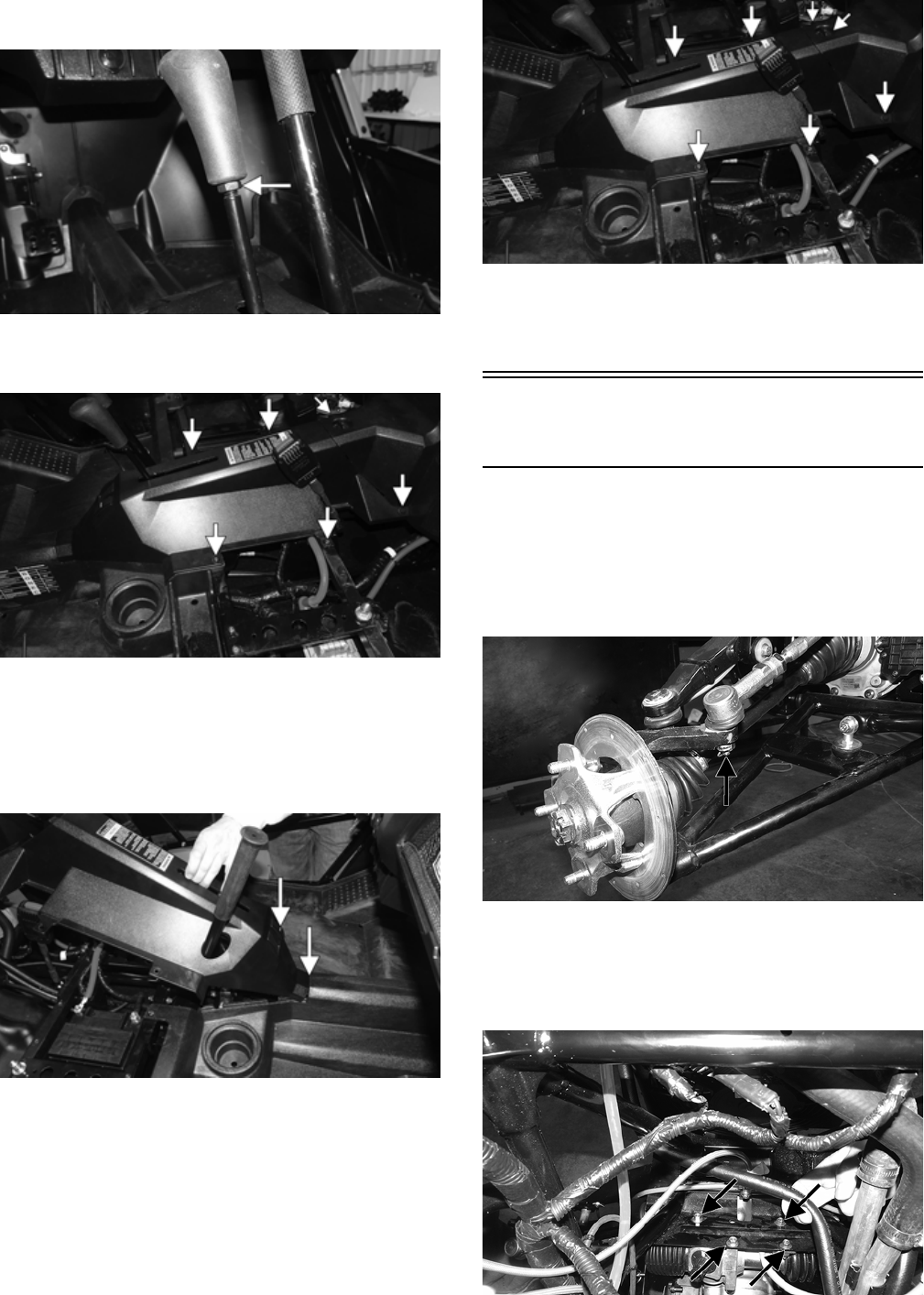
23
2. Loosen the jam nut below the shifter knob; then
unscrew the shifter knob.
WT274A
3. Remove the fasteners securing the center console;
then remove the console.
WT281A
INSTALLING
1. Install the center console over the passenger hand-
hold making sure the reverse override switch is con-
nected and the front tab is properly inserted under the
floor plastic.
WT286A
2. Secure the console with the existing cap screws and
push pins. Install the engine access panel and secure
with the quarter-turn screw.
WT281B
3. Install the shifter knob so the “P” is facing forward;
then tighten the jam nut to 12 ft-lb.
4. Install the seats.
Rack and Pinion
Assembly
REMOVING
1. Secure the vehicle on a support stand to elevate the
front of the vehicle; then remove the front wheels.
2. Remove and discard the cotter pin from the tie rod end
and remove the tie rod from the knuckle.
WT330A
3. Remove the steering wheel, dash, and steering shaft.
4. Remove the cap screws securing the rack and pinion
to the frame and remove from either side. Discard the
lock nuts.
WT369A
24
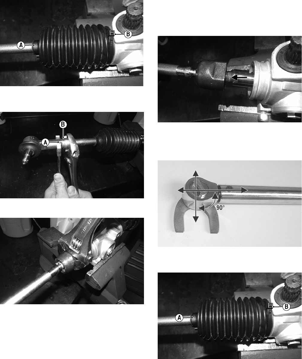
5. Support the steering rack assembly in a suitable bench
vise; then remove the clamp (A) and cut the cable tie
(B). Slide the boot to the center of the tie rod.
WT373A
6. While holding tie rod end (A), loosen jam nut (B) and
remove the tie rod end (A).
WT366A
7. Remove the inner tie rod from rack.
WT367
INSPECTING
1. Inspect the input shaft splines for excessive wear or signs
of misalignment.
2. Inspect the slide mechanism for pitting, excessive wear, or
worn bushings.
3. Rotate the input shaft from center to full left and right
checking for any binding or catching.
4. Check for loose cap screws on rack and pinion housing.
5. Check for seal damage or lubricant leaks.
NOTE: The steering assembly (rack and pinion) is
not repairable and must be replaced as an assembly;
however, the tie rods and boots are replaceable.
INSTALLING
1. With the threads coated with red Loctite #271, install
the tie rod into the rack and tighten with a crow-foot to
37 ft-lb.
WT370A
NOTE: Always attach the crow-foot to the torque
wrench with the open end 90° to the torque wrench
handle to ensure accurate torque application.
PR528A
2. Install the boot onto the rack and secure with the
clamp and nylon ties.
WT373A
3. With the jam nuts on the inner tie rod, install the tie
rod ends on to the inner tie rods. Do not tighten at this
point.
25
WT569
4. Center the tie rods in the steering rack assembly and
align the white paint line on the pinion with the white
paint line on the rack housing.
5. Install the rack and pinion assembly into the vehicle;
then using new lock nuts, secure to the frame and
tighten to 25 ft-lb.
WT369A
6. Install the steering shaft, dash, and steering wheel.
7. Tighten the tie rod jam nut to 25 ft-lb.
8. Install the tie rod ends into the hubs; then with the
threads coated in red Loctite #271, tighten the castle
nuts to 55 ft-lb and secure with a new cotter pin.
9. Install the wheels and adjust front wheel alignment
(see Checking/Adjusting Front Wheel Alignment).
10. Remove the vehicle from the support stand.
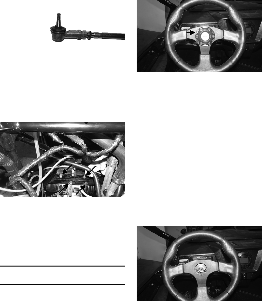
Steering Wheel
REMOVING
1. Remove the steering wheel cover; then mark the steer-
ing shaft and steering wheel for installing purposes.
WT298A
NOTE: Any time steering components are disas-
sembled, all connecting components should be
marked for proper alignment during assembling.
2. Remove the hairpin clip from the steering shaft; then
remove the nut securing the steering wheel and
remove the steering wheel.
INSPECTING
1. Inspect the steering wheel for cracks, missing pad-
ding, or broken spokes.
2. Inspect the splines for wear.
3. Check that the steering wheel is not bent.
INSTALLING
1. Install the steering wheel aligning the two match marks;
then secure the steering wheel. Tighten to 25 ft-lb.
NOTE: If a new steering wheel is being installed,
mark the wheel as close as possible to the old wheel
mark; then check for proper positioning with the front
wheels straight forward.
2. Install the hairpin clip on the steering shaft.
WT297
NOTE: If the hole in the steering shaft does not
align with the slots in the nut, tighten the nut slightly
until the next slot aligns with the hole.
26
Steering Shaft
REMOVING
1. Remove the steering wheel and hood; then remove the
dash.
2. Remove and discard the cap screws and lock nuts
securing the steering tilt assembly to the frame.
WT346
3. Remove the push pins securing the rubber boot to the
splash panel.
WT343A
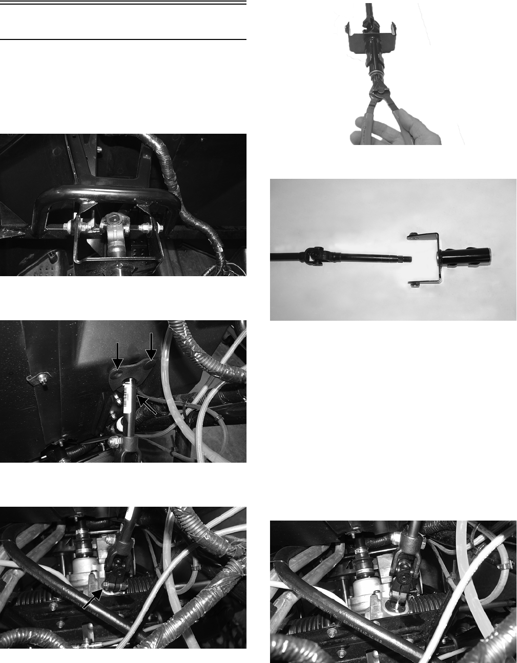
4. Remove the lower cap screw and discard the lock nut
securing the steering shaft to the rack and pinion.
WT345A
5. Remove the steering shaft through the splash panel.
6. Remove the snap ring. Account for the two washers.
WT594
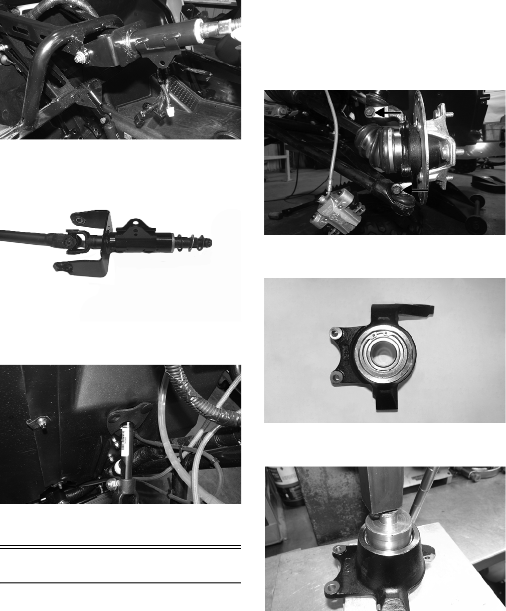
7. Slide the tilt assembly out of the steering shaft.
WT349
NOTE: Only the tilt assembly is a serviceable item.
If the shaft is damaged, it must be replaced.
INSPECTING
1. Check the splines for wear or signs of twisting.
2. Check the U-joints for any clicking or binding. If pres-
ent, the shaft must be replaced.
3. Check the tilt assembly for cracks or broken welds.
INSTALLING
1. Slide the steering shaft through the splash panel. With
both white lines on the rack and pinion aligned with
the gap in the lower knuckle on the steering shaft,
slide the steering shaft onto the splines.
WT348
2. Using the existing cap screw and new lock nut, secure
the steering shaft to the rack and pinion assembly.
Tighten to 25 ft-lb.
27
3. Install the tilt assembly onto the steering shaft and
secure it with new cap screws and lock nuts. Tighten
to 20 ft-lb.
WT351
4. Install the wave washer and washer; then install the
snap ring securing the shaft in place.
WT593
5. Install the rubber boot in place around the steering
shaft and secure with the existing push pins.
WT343
6. Install the dash; then install the steering wheel and
hood.
Steering Knuckles
REMOVING AND DISASSEMBLING
1. Secure the vehicle on a support stand to elevate the
wheel; then remove the wheel.
2. Remove the nut securing the hub.
3. Remove the brake caliper.
4. Remove the hub assembly.
5. Remove the cotter pin from the tie rod end and
remove the tie rod end from the knuckle.
6. Remove the upper cap screw securing the ball joint in
the knuckle.
7. Tap the ball joint end out of the knuckle; then slide the
axle out of the knuckle.
8. Remove the cap screw securing the lower ball joint to
the knuckle and remove the knuckle.
WT329A
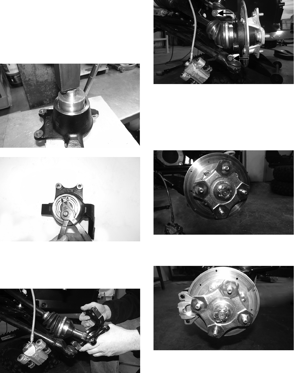
9. Remove the snap ring securing the bearing in the
knuckle; then press the bearing out of the knuckle.
WT326
10. Using a suitable press, remove the bearing from the
knuckle.
WT327
CLEANING AND INSPECTING
1. Clean all knuckle components.
28
2. Inspect the bearing for pits, scoring, rusting, or premature
wear.
3. Inspect the knuckle for cracks, breaks, or galling of
the bearing surface.
ASSEMBLING AND INSTALLING
1. Using a suitable press and driver, press the bearing
into the knuckle until firmly seated; then install the
snap ring.
WT327
WT331
2. Install the knuckle to the lower ball joint and secure with a
new “patch-lock” cap screw. Tighten to 35 ft-lb.
3. Slide the axle into the knuckle; then install the upper
ball joint and secure with a new “patch-lock” cap
screw. Tighten to 35 ft-lb.
WT332
WT329A
4. Install the tie rod end and secure with the nut (coated
with red Loctite #263). Tighten to 30 ft-lb; then install
a new cotter pin and spread the pin.
NOTE: During assembling, new cotter pins should
be installed.
5. Install the hub assembly onto the axle; then secure the
hub using the hub nut.
WT451
6. Tighten the hub nut to 200 ft-lb; then install a new cot-
ter pin and spread the pin making sure the side of the
pin is flush to the hub nut.
WT275
NOTE: During assembly, new cotter pins should
always be used.
NOTE: If the cotter pin cannot be inserted due to
misalignment of the hole and the slots in the nut,
always tighten the nut until it is properly aligned.
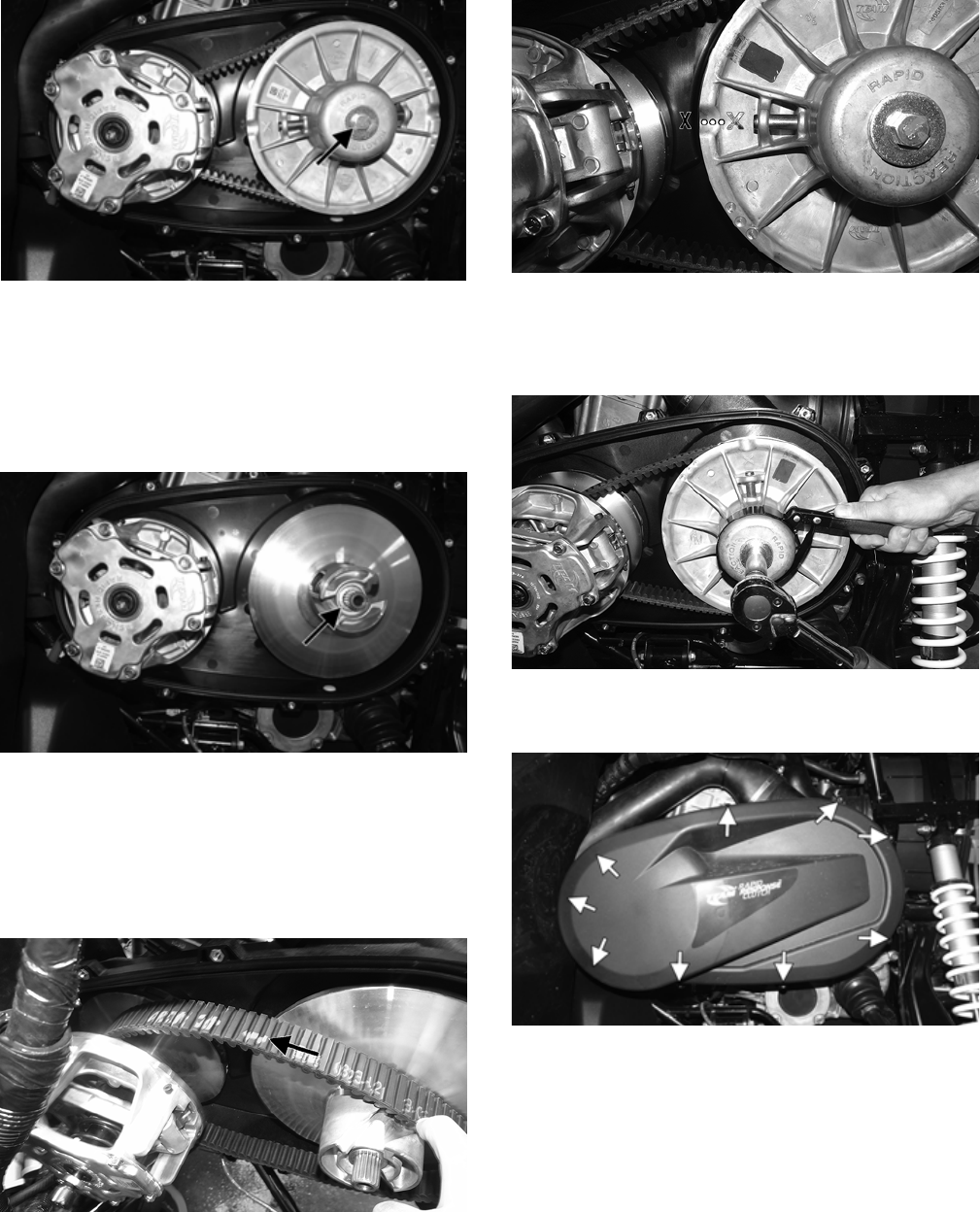
7. Secure the brake caliper to the knuckle with the two
new “patch-lock” cap screws. Tighten to 20 ft-lb.
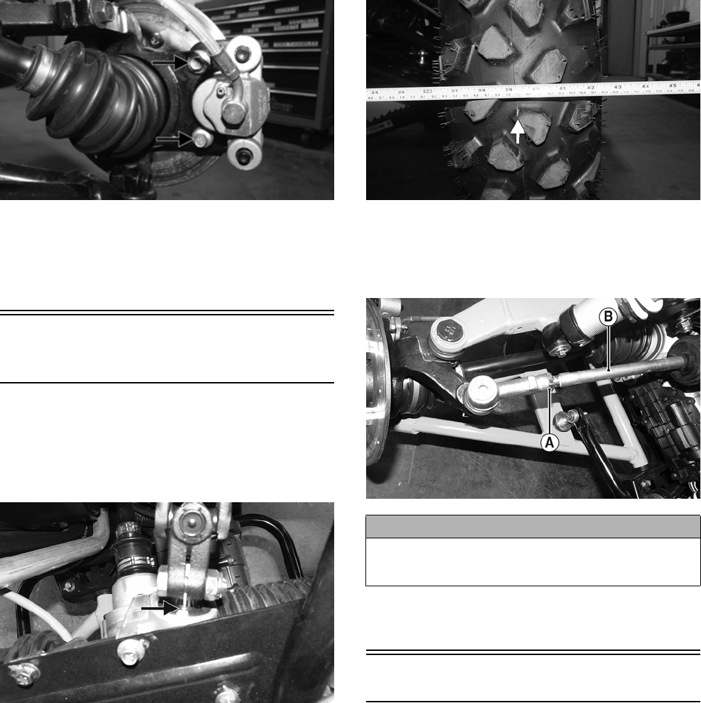
29
WT287A
9. Install the wheel; then using a crisscross pattern,
tighten the wheel nuts in 20 ft-lb increments to a final
torque factor of 40 ft-lb (steel wheel) or 80 ft-lb (alu-
minium wheel).
10. Remove the vehicle from the support stand.
Checking/Adjusting Front
Wheel Alignment
NOTE: All measurements and adjustments must be
made with the vehicle unloaded.
NOTE: Make sure the white alignment marks of the
steering rack are aligned.
WT080A
Mark the center-line of the front tires at the front and rear
of the tire; then using a tape measure, measure and record
the distance between the marks at the front and rear. The
front measurement should be 3-6 mm (1/8-1/4 in.) greater
than the rear measurement (toe-out).
WT292A
To adjust the wheel alignment, use the following procedure:
1. Center the steering rack; then using an open-end
wrench to hold the tie rod (B), loosen the right-side
and left-side jam nuts (A).
WT039A
2. Turn the left-side and right-side tie rods (B) in equal
increments to achieve the proper toe-out; then tighten
to 25 ft-lb.
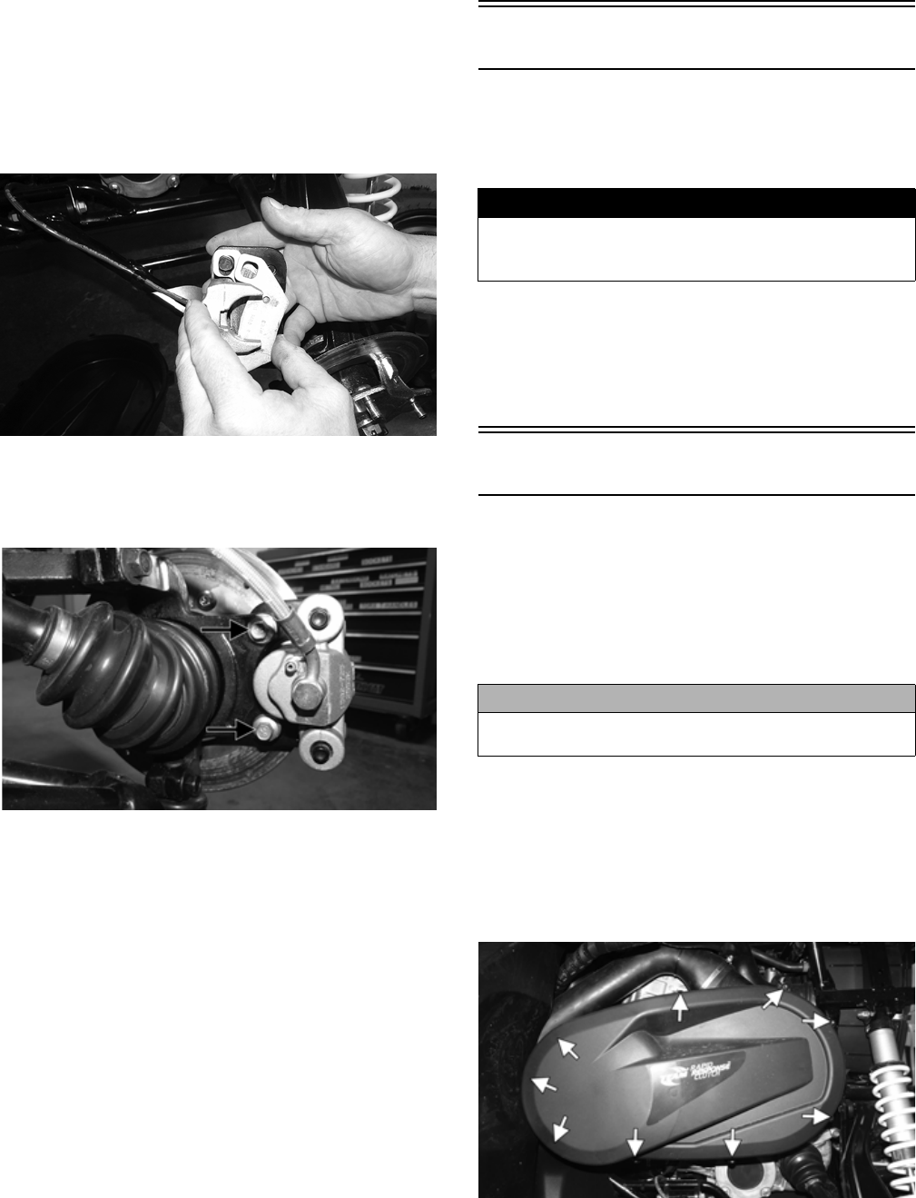
Accelerator Pedal
REMOVING
Dislodge the yellow nylon bushing of the throttle cable
from the actuator arm; then remove two torx-head screws
and nuts securing the accelerator pedal assembly to the
splash panel and remove the accelerator pedal.
CAUTION
Always use a wrench to hold the tie rod ends when loos-
ening or tightening the jam nuts or damage to the boots
could occur.
30
WT099C
WT288A
INSTALLING
Align the mounting holes with the holes in the splash panel
and secure with the two torx-head screws and new lock nuts;
then tighten to 10 ft-lb. Snap the throttle cable bushing into
the actuator arm.
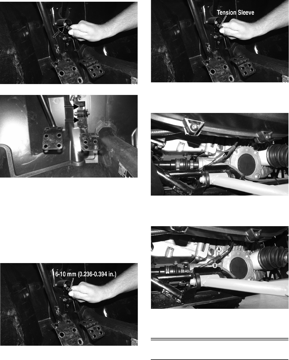
CHECKING CABLE FREE-PLAY
1. Check cable free-play by grasping the cable at the top
of the accelerator pedal and lightly pulling rearward to
remove slack. Free-play should be 1-2 mm (0.040-
0.080 in.).
WT099A
2. Depress the accelerator pedal completely and pull
rearward on the cable end. There should not be any
free-play and the tension sleeve should not be com-
pressed.
WT099B
3. To adjust the throttle cable, locate the in-line cable
adjuster beneath the clutch cover; then slide the pro-
tective sleeve upward from the adjuster.
WT081A
4. Loosen the jam nut (A) and turn the adjuster (B)
clockwise to increase free-play or counterclockwise to
decrease.
WT082A
5. Tighten the jam nut securely and slide the protective
sleeve over the adjuster making sure the sleeves over-
lap over the seal.
Shift Lever
REMOVING
1. Remove the seats, shifter knob, and center console.
31
WT281B
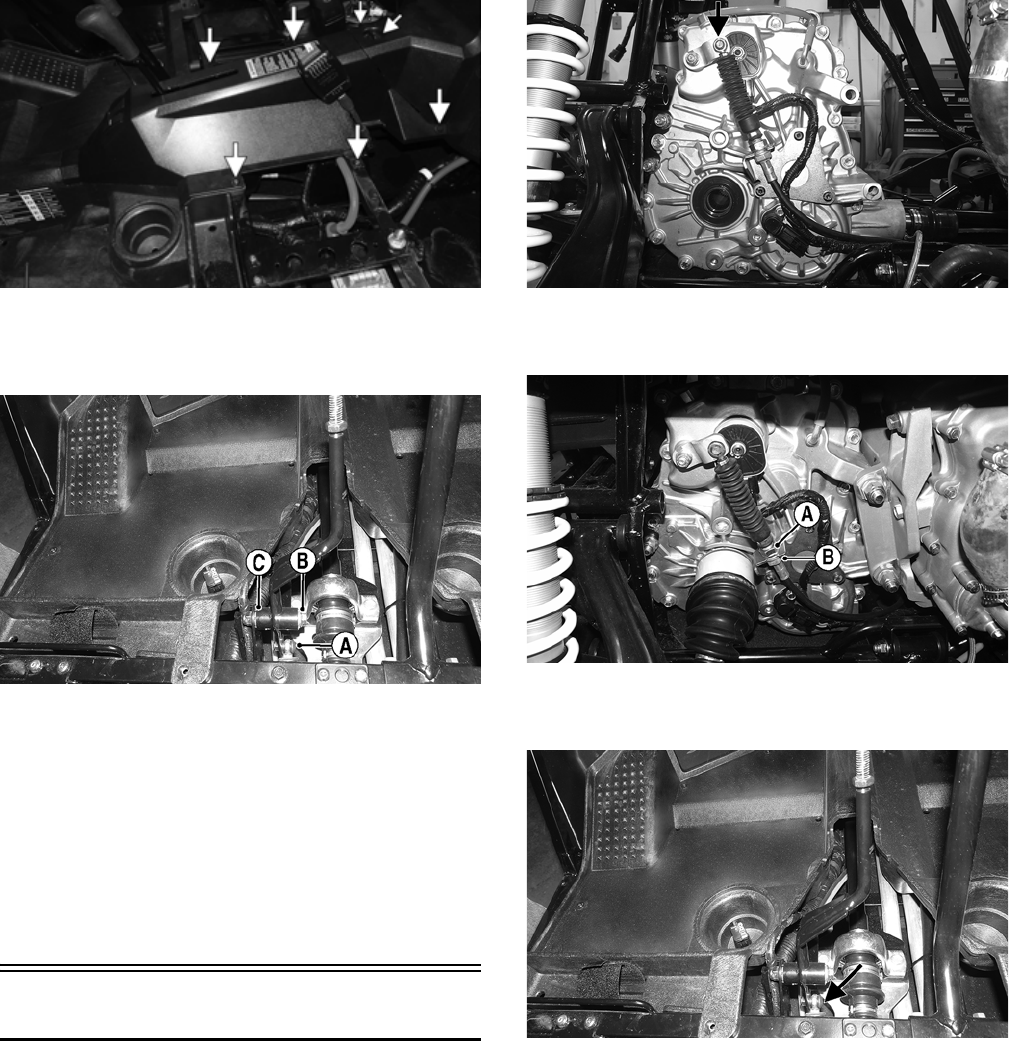
2. Remove the cap screw from the shift cable pivot bolt
(A), remove the axle bolt (B), and account for plastic
inserts (C).
WT296A
3. Remove the shift lever.
INSTALLING
1. Connect the shift cable to the shift arm with the pivot
bolt and new lock nut. Tighten to 8 ft-lb.
2. Place the shift lever into position and secure with the
axle bolt, plastic inserts, and new lock nut. Tighten to
20 ft-lb.
3. Install the center console, shifter knob, and seats.
Make sure the seats lock securely in place.
Shift Cable
REMOVING
1. Remove the seats and center console.
2. Remove the E-clip securing the shift cable to the
transaxle.
WT439B
3. While holding the nut (B), loosen the jam nut (A) and
remove the shift cable from the transaxle.
WT225B
4. Remove the cap screw and lock nut securing the shift
cable to the shift arm. Discard the nut.
WT296B
5. Cut the plastic wire ties securing the cable to frame
noting their locations for installing.
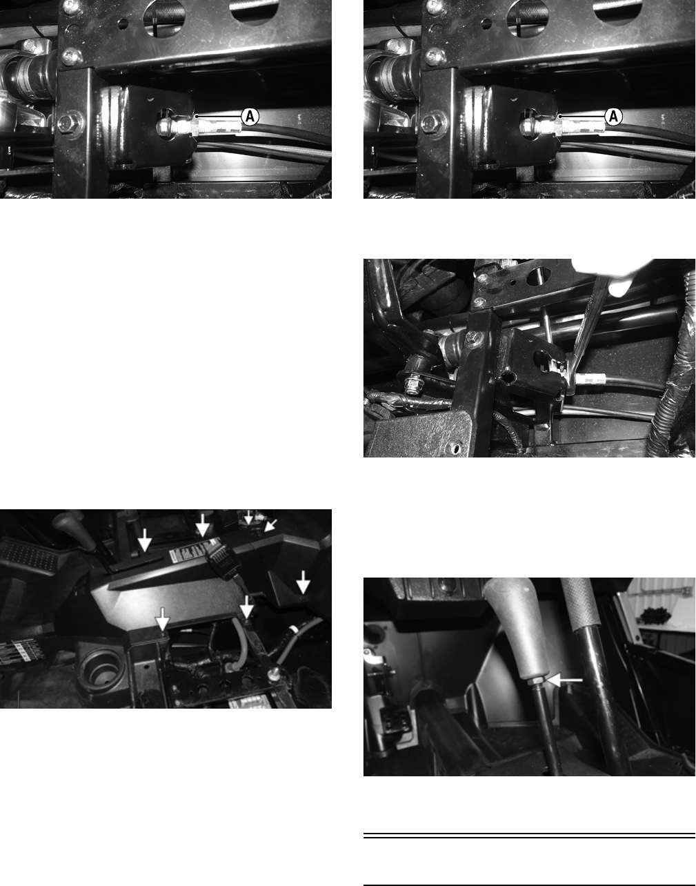
6. Loosen the jam nut (A) securing the shift cable on the
shifter bracket and remove the shift cable noting the
cable location for installing.
32
WT276A
INSTALLING
1. Install the new shift cable in place noting the routing from
removing. Secure to the transaxle with the E-clip and jam
nut. Finger-tighten the jam nut at this point.
2. Install the shift cable end to the shifter bracket and secure
with the cap screw, new lock nut, and jam nuts.
3. Install any necessary cable ties as marked during remov-
ing; then adjust the shift cable (see ADJUSTING in this
sub-section). After cable is properly adjusted, tighten the
jam nuts to 20 ft-lb.
4. Install the center console and seats. Make sure the
seats lock securely in place.
ADJUSTING
1. Remove the seats, shifter knob, engine access panel,
and center console.
WT281B
2. With the transmission in neutral, loosen the jam nut
(A) and adjust the cable until there is a small amount
of free-play in the shift lever moving forward and
backward while still in neutral.
WT276A
3. Once the proper adjustment is achieved, tighten the
jam nut to 20 ft-lb.
WT342
NOTE: After the jam nuts are secure, check the shift
cable again for proper adjustment.
4. Install the center console and engine access panel.
5. Install the shifter knob and tighten the jam nut to 12 ft-lb.
WT274A
6. Install the seats. Make sure the seats lock securely in
place
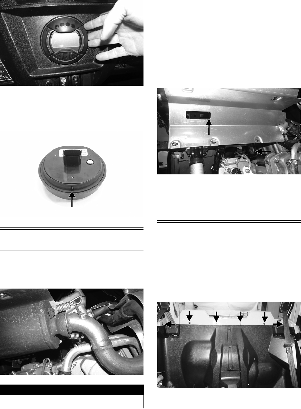
LCD Gauge
REMOVING/INSTALLING
To remove the gauge, pull out on one side of it; then dis-
connect the multi-pin connector and remove the gauge.
33
WT339
To install the gauge, connect the multi-pin connector and
press the gauge into the dash.
NOTE: Ensure the rubber mounting ring is oriented
correctly on the tab and seats fully through the dash.
WT601A
Exhaust System
REMOVING MUFFLER
1. Remove the two exhaust springs at the muffler/
exhaust pipe juncture.
WT295
2. Slide the muffler assembly clear of the holder pins.
Account for the exhaust gasket.
INSPECTING MUFFLER
1. Inspect muffler externally for cracks, holes, and dents.
2. Inspect the muffler internally by shaking the muffler
back and forth and listening for rattles or loose debris
inside the muffler.
NOTE: For additional details on cleaning the muffler/
spark arrester, see Periodic Maintenance/Tune-Up.
INSTALLING MUFFLER
1. With the gasket in place, place the muffler onto the
holder pins and slide into position.
WT293A
NOTE: Starting with the upper rear pin will aid in
installing.
2. Secure the muffler to the exhaust pipe with the two
exhaust springs.
Cargo Box
REMOVING
1. Remove the seats and rear fenders.
2. Remove the LED taillight assembly.
3. Remove the fasteners securing the upper rear body
panel to the splash guard.
WT229A
4. Remove the fasteners securing the cargo box.
! WARNING
The heat deflector under the right-rear fender has sharp
edges and can cause serious injury if care is not taken.
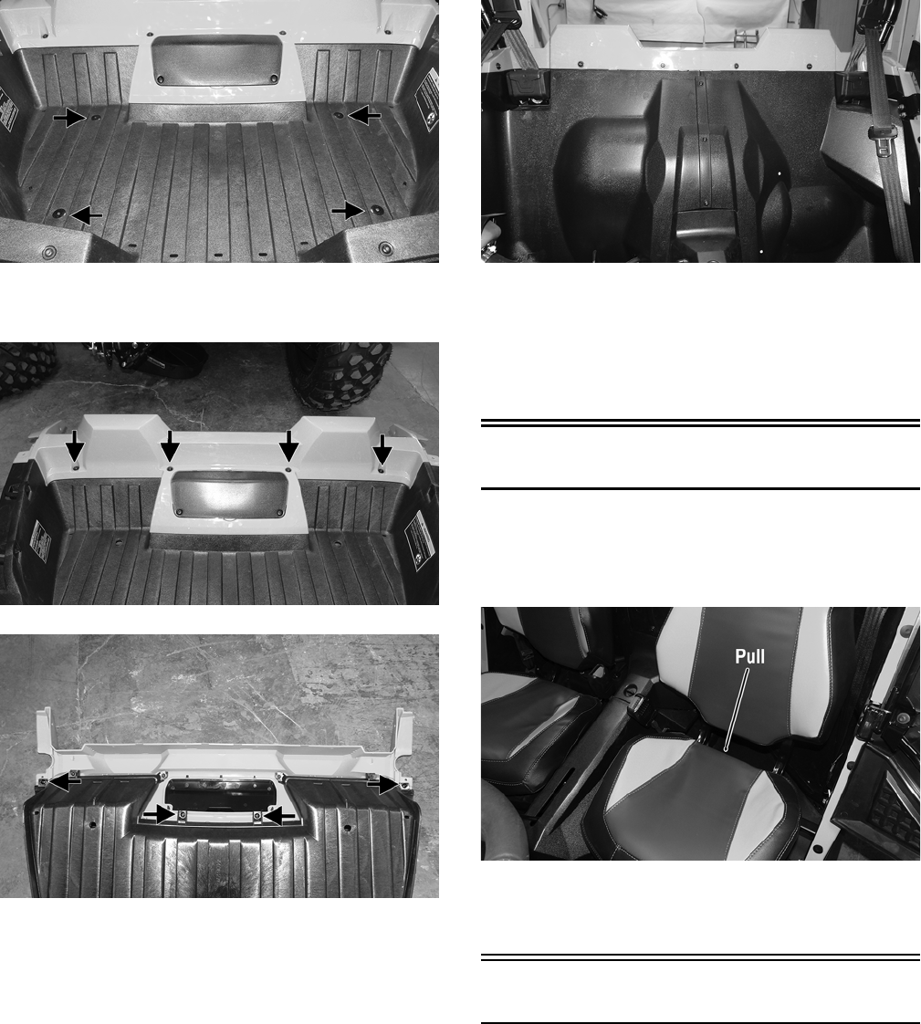
34
WT234A
5. Remove the fasteners securing the upper rear body
panel to the cargo box.
WT230A
WT231A
INSTALLING
1. Secure the upper rear body panel to the cargo box and
tighten the cap screws to 15 in.-lb.
2. Install the cargo box into position so the upper body
panel is over the top of splash guard; then tighten the
cap screws to 5 ft-lb.
WT229
3. Secure the cargo box with self tapping screws and
tighten to 5 ft-lb.
4. Install the LED taillight assembly.
5. Install the rear fenders; then install the seats making
sure they lock securely in place.
Seats
REMOVING/INSTALLING
1. To remove a seat, pull the seat lock lever up. Raise the
rear of the seat and tilt it forward.
WT003A
2. To install a seat, slide the front of the seat into the seat
retainers and push down firmly on the rear of seat. The
seat should automatically lock into position.
Doors
CHECKING/ADJUSTING
NOTE: The ROPS must be fully installed whenever
adjusting the doors in any way.
Inspect the doors for broken or bent tubes, hinges, or
latches. Make sure the latches engage and lock securely; if
not, us the following instructions.
1. Open the door to ensure it swings freely. If not, loosen
the two top fasteners and adjust door as necessary
until it swings freely. Tighten the fasteners securely.
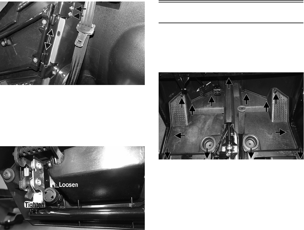
35
WT110A
2. Close the door to ensure it latches securely. If not,
loosen the fasteners and adjust the latch up or down
until the door latches securely. Tighten the fasteners
securely.
3. With the door closed, ensure the rubber bumper con-
tacts the latch. To adjust, turn the bumper in (loosen)
or out (tighten).
WT108A
Floor
REMOVING
1. Remove the seats, engine access panel, and center
console.
2. Remove the fasteners securing the floor to the frame.
WT344A
CLEANING AND INSPECTING
1. Clean any debris from underneath the floor.
2. Inspect the floor for any cracks or holes.
INSTALLING
1. Install the floor into position and secure it with the
existing cap screws. Tighten securely.
2. Install the center console, engine access panel, and
seats. Make sure the seats lock securely in place.

36
Troubleshooting
Problem: Handling too heavy or stiff
Condition Remedy
1. Front wheel alignment incorrect
2. Lubrication inadequate
3. Tire inflation pressure incorrect
4. Tie rod ends seizing
5. Linkage connections seizing
1. Adjust alignment
2. Lubricate appropriate components
3. Adjust pressure
4. Replace tie rod ends
5. Repair - replace connections
Problem: Steering oscillation
Condition Remedy
1. Tires inflated unequally
2. Wheel(s) wobbly
3. Wheel hub cap screw(s) loose - missing
4. Wheel hub bearing worn - damaged
5. Tie rod ends worn - loose
6. Tires defective - incorrect
7. A-arm bushings damaged
8. Bolts - nuts (frame) loose
1. Adjust pressure
2. Replace wheel(s)
3. Tighten - replace cap screws
4. Replace bearing
5. Replace - tighten tie rod ends
6. Replace tires
7. Replace bushings
8. Tighten bolts - nuts
Problem: Steering pulling to one side
Condition Remedy
1. Tires inflated unequally
2. Front wheel alignment incorrect
3. Wheel hub bearings worn - broken
4. Frame distorted
5. Shock absorber defective
1. Adjust pressure
2. Adjust alignment
3. Replace bearings
4. Repair - replace frame
5. Replace shock absorber
Problem: Steering impaired
Condition Remedy
1. Tire pressure too high
2. Steering linkage connections worn
3. Cap screws (suspension system) loose
1. Adjust pressure
2. Replace connections
3. Tighten cap screws
Problem: Tire wear rapid or uneven
Condition Remedy
1. Wheel hub bearings worn - loose
2. Front wheel alignment incorrect
1. Replace bearings
2. Adjust alignment
Problem: Steering noise
Condition Remedy
1. Caps screws - nuts loose
2. Wheel hub bearings broken - damaged
3. Lubrication inadequate
1. Tighten cap screws - nuts
2. Replace bearings
3. Lubricate appropriate components
Problem: Rear wheel oscillation
Condition Remedy
1. Rear wheel hub bearings worn - loose
2. Tires defective - incorrect
3. Wheel rim distorted
4. Wheel hub cap screws loose
5. Rear suspension lateral link bushing worn
6. Trailing arm bushings worn
7. Rear suspension lateral link loose
1. Replace bearings
2. Replace tires
3. Replace wheel
4. Tighten cap screws
5. Replace bushing
6. Replace bushings or link
7. Tighten nut or replace

37
Engine
This section has been organized into sub-sections which
show a progression for the complete servicing of the Arc-
tic Cat Wildcat Trail engine.
To service bottom-side components, the engine must be
removed from the frame. To service top-side or left-side
components, the engine does not have to be removed from
the frame.
NOTE: Arctic Cat recommends the use of new gas-
kets, lock nuts, and seals and lubricating all internal
components when servicing the engine.
NOTE: A new ROV and an overhauled ROV engine
require a “break-in” period. The first 10 hours (or 200
miles) are most critical to the life of this ROV. Proper
operation during this break-in period will help assure
maximum life and performance from the ROV. Instruct
the customer to follow the proper break-in procedure
as described in the Operators Manual.
SPECIAL TOOLS
A number of special tools must be available to the techni-
cian when performing service procedures in this section.
Refer to the current Special Tools Catalog for the appropri-
ate tool description.
NOTE: Special tools are available from the Arctic
Cat Service Department.
Description p/n
Magneto Rotor Remover Set 0444-254
Piston Pin Puller 0644-328
Spanner Wrench 0444-240
Surface Plate 0644-016
V Blocks 0644-535
Clutch Alignment Bar 0544-027
Clutch Puller 0744-080

38
Troubleshooting
Problem: Engine will not start or is hard to start (Compression too low)
Condition Remedy
1. Gasoline bad - contaminated
2. Valve clearance out of adjustment
3. Valve guides worn
4. Valves mistimed
5. Piston rings worn - broken
6. Cylinder bore worn
7. Starter motor cranks too slowly - does not turn
1. Drain gas - replace with clean gas
2. Adjust clearance
3. Replace cylinder head
4. Retime engine
5. Replace rings
6. Replace cylinder
7. See Electrical System
Problem: Engine will not start or is hard to start (No spark)
Condition Remedy
1. Spark plug(s) fouled
2. Spark plug(s) wet
3. Magneto defective
4. ECM defective
5. Ignition coil defective
6. High-tension lead open - shorted
1. Clean - replace plug(s)
2. Clean - dry plug(s)
3. Replace stator coil
4. Replace ECM
5. Replace ignition coil
6. Replace high tension lead
Problem: Engine will not start or is hard to start (No fuel reaching the fuel injector)
Condition Remedy
1. Gas tank vent hose obstructed
2. Fuel hose obstructed
3. Fuel screens obstructed
4. Fuel pump defective
1. Clean vent hose
2. Clean - replace hose
3. Clean - replace inlet screen
4. Replace fuel pump
Problem: Engine stalls easily
Condition Remedy
1. Gasoline bad - contaminated
2. Spark plug(s) fouled
3. Magneto defective
4. ECM defective
5. Fuel injector obstructed
6. Valve clearance out of adjustment
1. Drain gas - replace with clean gas
2. Clean - replace plug(s)
3. Replace stator coil
4. Replace ECM
5. Replace fuel injector
6. Adjust clearance
Problem: Engine noisy (Excessive valve chatter)
Condition Remedy
1. Valve clearance excessive
2. Valve spring(s) weak - broken
3. Camshaft worn
1. Adjust clearance
2. Replace spring(s)
3. Replace camshaft
Problem: Engine noisy (Noise seems to come from piston)
Condition Remedy
1. Piston - cylinder worn
2. Combustion chamber carbon buildup
3. Piston pin - piston pin bore worn
4. Piston rings - ring groove(s) worn
1. Replace - service piston - cylinder
2. Clean cylinder head and piston
3. Replace - service pin - replace connecting rod
4. Replace rings - piston
Problem: Engine noisy (Noise seems to come from timing chain)
Condition Remedy
1. Chain stretched
2. Sprockets worn
3. Tension adjuster malfunctioning
1. Replace chain
2. Replace sprockets
3. Repair - replace adjuster
Problem: Engine noisy (Noise seems to come from crankshaft)
Condition Remedy
1. Main bearing worn - burned
2. Lower rod-end bearing worn - burned
3. Rotor/flywheel loose
1. Replace bearing
2. Replace bearing
3. Tighten - replace flywheel - crankshaft
Problem: Engine noisy (Noise seems to come from crankcase)
Condition Remedy
1. Gears worn - chipped
2. Splines worn
3. Bearings worn
4. Bushing worn
1. Replace gears
2. Replace shaft(s)
3. Replace bearings
4. Replace bushing

39
Problem: Engine idles poorly
Condition Remedy
1. Gasoline bad - contaminated
2. Valve clearance incorrect
3. Valve seating poor
4. Valve guides defective
5. Magneto defective
6. ECM defective
7. Spark plug(s) fouled - gap too wide
8. Ignition coil defective
9. Fuel injector obstructed
10. Throttle body dirty
1. Drain gas - replace with clean gas
2. Adjust clearance
3. Replace valves/cylinder head
4. Replace cylinder head
5. Replace stator coil
6. Replace ECM
7. Adjust gap - replace plug(s)
8. Replace ignition coil
9. Replace fuel injector
10. Clean bore and ISA passages
Problem: Engine runs poorly at high speed
Condition Remedy
1. Gasoline bad - contaminated
2. High RPM “cut out” against RPM limiter
3. Valve springs weak
4. Valve timing incorrect
5. Cams worn
6. Spark plug gap too narrow
7. Ignition coil defective
8. Air cleaner element obstructed
9. Fuel hose obstructed
1. Drain gas - replace with clean gas
2. Shift into higher gear - decrease speed
3. Replace springs
4. Retime engine
5. Replace cams
6. Adjust gap
7. Replace ignition oil
8. Clean element
9. Clean - prime hose
Problem: Exhaust smoke dirty or heavy
Condition Remedy
1. Gasoline bad - contaminated
2. Engine oil overfilled - contaminated
3. Piston rings - cylinder worn
4. Valve guides worn
5. Cylinder wall scored
6. Valve stems worn
7. Stem seals defective
1. Drain gas - replace with clean gas
2. Drain excess oil - change oil
3. Replace - service rings - cylinder
4. Replace cylinder head
5. Replace cylinder
6. Replace valves
7. Replace seals
Problem: Engine lacks power
Condition Remedy
1. Gasoline bad - contaminated
2. Valve clearance incorrect
3. Valve springs weak
4. Valve timing incorrect
5. Piston ring(s) - cylinder worn
6. Valve seating poor
7. Spark plug fouled
8. Spark plug gap incorrect
9. Fuel injector obstructed
10. Air cleaner element obstructed
11. Engine oil overfilled - contaminated
12. Intake manifold leaking air
13. Cam chain worn
1. Drain gas - replace with clean gas
2. Adjust clearance
3. Replace springs
4. Time camshaft
5. Replace - service rings - cylinder
6. Repair seats
7. Clean - replace plug
8. Adjust gap - replace plug
9. Replace fuel injector
10. Clean element
11. Drain excess oil - change oil
12. Tighten - replace manifold
13. Replace cam chain - sprockets
Problem: Engine overheats
Condition Remedy
1. Carbon deposit (piston crown) excessive
2. Oil low
3. Octane low - gasoline poor
4. Oil pump defective
5. Oil filter obstructed
6. Intake manifold leaking air
7. Coolant level low
8. Fan malfunctioning
9. Fan relay malfunctioning
10. Thermostat stuck - closed
11. Radiator hoses - cap damaged - obstructed
12. Fan fuse(s) blown
1. Clean piston
2. Add oil
3. Drain - replace gasoline
4. Replace pump
5. Replace filter
6. Tighten - replace manifold
7. Fill - examine system for leaks
8. Check fan fuse - replace fan
9. Replace fan relay
10. Replace thermostat
11. Clear obstruction - replace hoses - cap
12. Replace fuse(s)
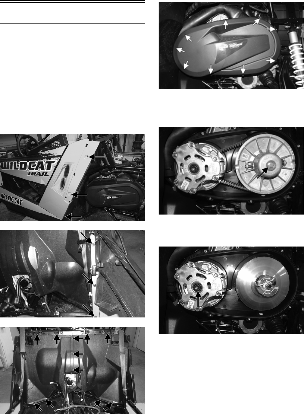
40
Removing Engine
Many service procedures can be performed without
removing the engine from the frame. Closely observe the
note introducing each sub-section for this important infor-
mation.
NOTE: To remove the engine, the taillight assembly,
left side panel, and left rear body panel must be
removed (see Steering/Frame/Controls).
NOTE: The vehicle must be supported on an appro-
priate stand for this procedure.
1. Remove the rear cargo box and rear fenders; then
remove the cap screws securing the rear splash panels
to the frame.
WT488A
WT489A
WT362A
2. Remove the left-rear wheel; then remove the outer
clutch cover. Retain the cap screws.
WT182A
3. Remove the cap screw securing the driven clutch to
the output shaft; then remove the stationary sheave of
the driven clutch along with the belt. Account for a
flat washer.
WT183A
4. Remove the cap screw securing the drive clutch.
Using an appropriate clutch puller, remove the drive
clutch. Remove the driven pulley moveable sheave.
WT186B
NOTE: When removing the stationary sheave,
account for the alignment shims (see Installing Left-
Side Components in the Engine section for proper
shimming).
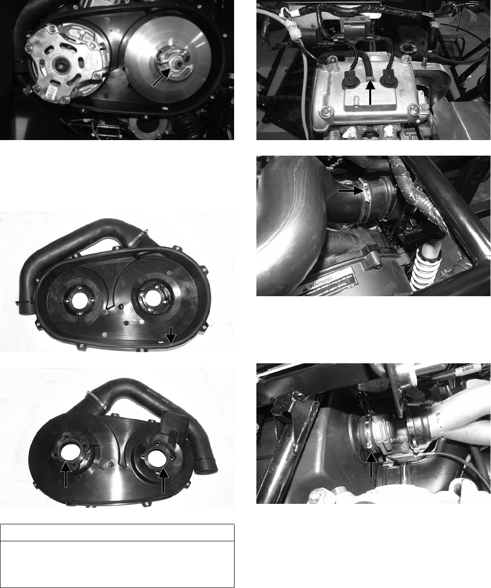
41
WT186A
5. Remove and retain the cap screws securing the inner
clutch cover; then with the air outlet duct connected to
the inner clutch cover, remove the cover as an assem-
bly. Account for the rubber O-rings on both sides of
the cover.
WT443A
WT442A
6. Remove the clamp on the breather tube and loosen the
air intake clamp.
WT405A
WT311A
NOTE: Removing the intake boot with air box will
aid in installation.
7. Loosen the throttle body clamp.
WT316A
8. Remove and discard the top “patch-lock” fasteners
securing the air box; then remove and retain the lower
air box cap screws and grommets.
AT THIS POINT
If the technician's objective is to service the left-side
components, no further disassembling is necessary.
Proceed to Servicing Left-Side Components in this
section.
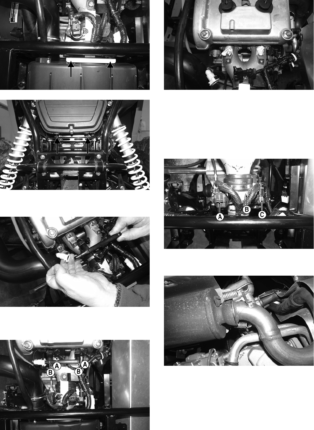
42
WT313A
WT315A
9. Remove the air filter housing; then remove the gaso-
line hose from the fuel rail.
WT402
10. Disconnect the injectors (A). Remove and retain the
cap screws (B) securing the fuel rail to the intake man-
ifold.
WT404A
WT400
NOTE: Plug the holes with paper towels to keep
contaminates from falling inside.
11. Remove the ISC connector (A), MAP/IAT connector
(B), and the TPS connector (C); then loosen the clamp
securing the throttle body to the intake manifold.
Leave it connected to the throttle cable and set the
throttle body off to the side.
WT397A
12. Remove the springs securing the exhaust pipe to the
muffler; then remove muffler.
WT295
13. Remove the cap screws securing the heat shield to the
exhaust pipe; then carefully remove the heat shield
leaving the oxygen (O2) sensor in the exhaust pipe.
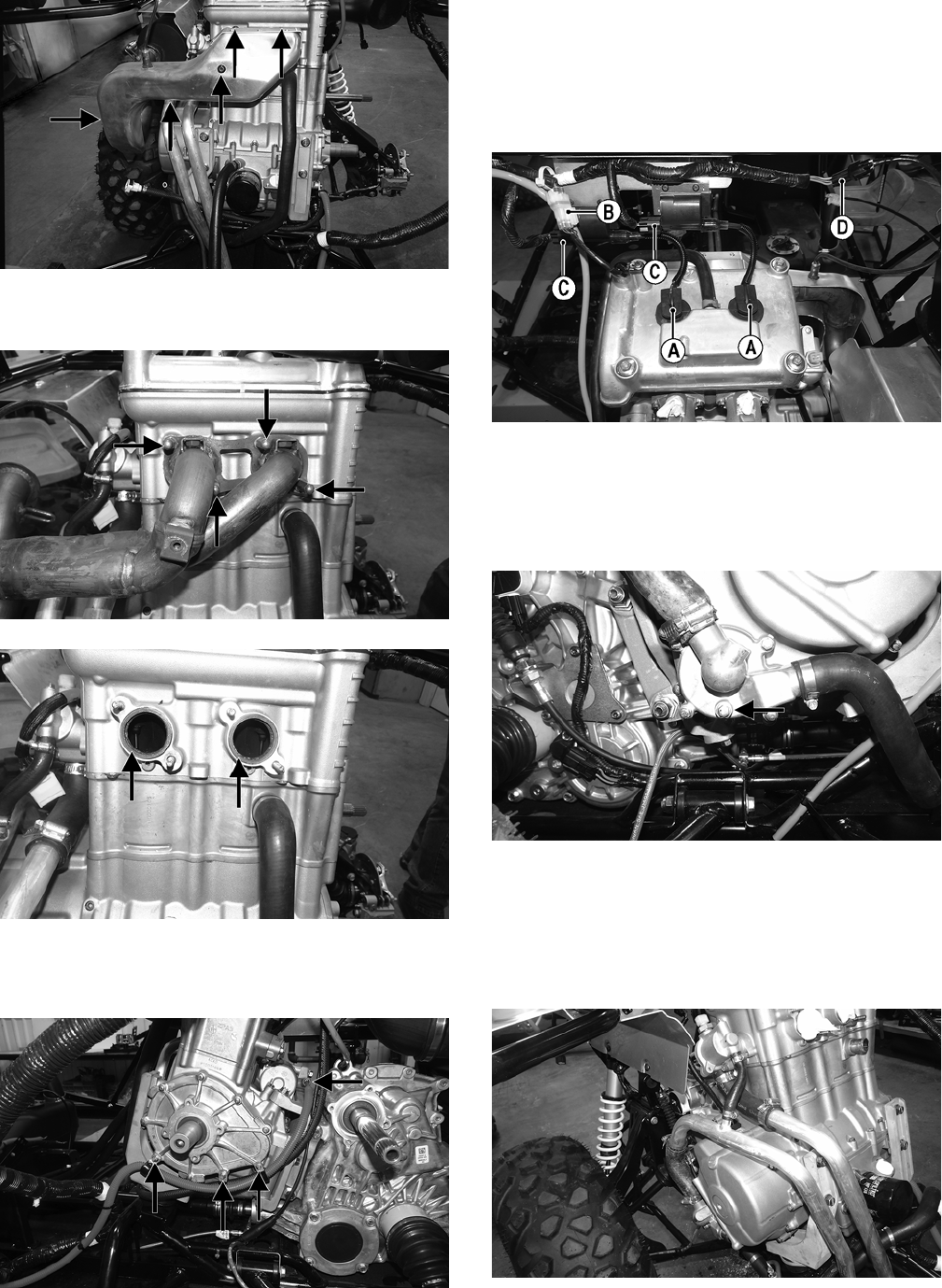
43
WT403A
14. Remove the exhaust pipe. Account for two exhaust
gaskets.
WT398A
WT406A
15. Remove the positive cable from the starter; then
remove the three cap screws securing the positive
cable to the PTO cover leaving the clips on the cable.
WT414A
NOTE: After removing the cap screws, install them
in their original position in the engine. Tighten
securely.
16. Remove the spark plug caps (A). Disconnect the cam
position sensor (B), coil connectors (C), and oxygen
(O2) sensor (D).
WT405B
NOTE: Leave the oxygen (O2) sensor in the exhaust
pipe.
17. Remove the water pump drain plug and drain the cool-
ant into a suitable pan.
WT399A
NOTE: Opening the radiator cap will aid in draining
the coolant.
18. Remove the coolant hoses from the water pump and
thermostat housing. Disconnect the ECT connector
and tie the coolant pipe out of the way.
WT411
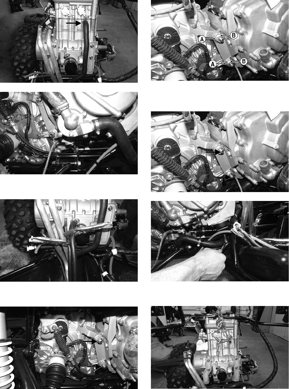
44
19. Remove the coolant hose connecting the water pump
to the cylinder.
WT410A
WT399
20. Using appropriate clamps, clamp off oil lines and
remove them from the oil fittings.
WT394
21. Remove and discard the lock nuts on the transaxle
mounting plate.
WT225A
22. Loosen the jam nut (A); then loosen the adjuster nut
(B) but do not remove it from plate.
WT412A
23. Remove the cap screws securing the transaxle to the
engine plate; then remove the cap screws securing the
front of the engine to the frame.
WT 412B
WT407
24. Using a proper lifting device, remove the engine from
the vehicle.
WT413
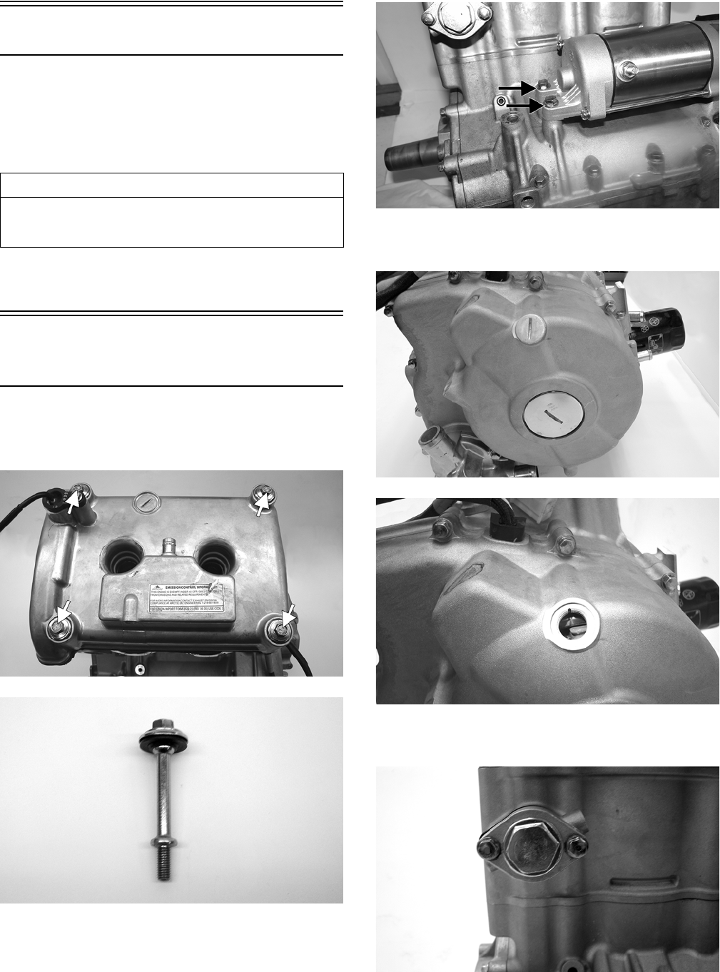
45
Top-Side Components
NOTE: For efficiency, it is preferable to remove and
disassemble only those components which need to
be addressed and to service only those components.
The technician should use discretion and sound
judgment.
NOTE: The engine does not need to be removed for
this procedure.
Removing Top-Side
Components
1. Remove the four cap screws securing the cylinder
head cover. Account for rubber washers and silicone-
held gaskets.
ROV1-005A
ROV1-001A
2. Remove the two fasteners securing the starter motor.
ROV1-116A
3. Remove the magneto and timing inspection plug;
then turn the crankshaft to the TDC position.
ROV1-012
ROV1-013
4. Remove the cam chain tensioner. Account for a gas-
ket and the fasteners.
ROV1-002
5. Remove the chain guide.
AT THIS POINT
To service any one specific component, only limited dis-
assembly of components may be necessary. Note the
AT THIS POINT information in each sub-section.
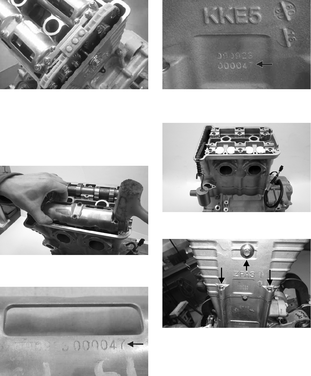
46
KC520
NOTE: Take care not to drop the fasteners down into
engine.
6. Remove the cap screws securing the intake and exhaust
camshaft retainers.
NOTE: Tapping on the end of the camshaft holder with
a rubber mallet opposite the sprocket will aid in remov-
ing the camshaft holder.
ROV1-010
NOTE: The camshaft holder and cylinder head have
matching code numbers and must remain a set.
KC548A
KC549A
7. Lift on the chain and remove both camshafts and
sprockets; then using a suitable holder, hook the
chain and let it hang over the side of the head.
ROV1-019
8. On the right side of the head, remove the three cap
screws.
ROV1-021A
9. Loosen the six head bolts securing the cylinder head
to the cylinder.
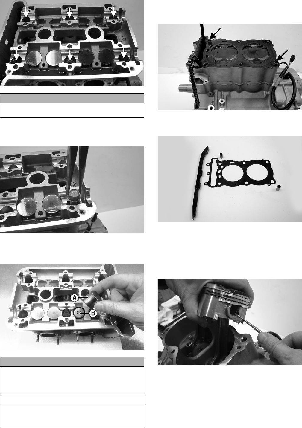
47
ROV1-015A
10. Using a needle nose pliers or magnet, remove the
head bolts. Note the location of the two longer bolts
for installing purposes. Account for the washers.
ROV1-020
11. Using a magnet or needle-nose pliers, carefully
remove the tappets (A) from the cylinder head and
account for the shims (B).
WT471A
12. Remove the cylinder head making sure not to let the
chain fall down into engine. Account for two dowel
pins.
ROV1-040A
13. Remove the head gasket, chain guide, and two dowel
pins. Discard the head gasket.
ROV1-038
14. Taking care not to let the pistons fall against the cyl-
inder, remove the cylinder and account for two
dowel pins. Remove and discard the base gasket.
15. Using a suitable pick, remove the circlip from the
piston; then push the piston pin out from the other
side.
ROV1-043
NOTE: Only one piston circlip needs to be removed.
CAUTION
Do not use an impact tool to remove the head bolts or
damage to the cam shaft journals could occur.
CAUTION
When removing the tappets, note the location of the tap-
pet, the valve from which the tappet was removed, and
the shim number of the tappet or severe engine damage
may occur.
AT THIS POINT
If the technician’s objective is to measure valve/tap-
pet clearance, proceed to Servicing Top-Side Com-
ponents
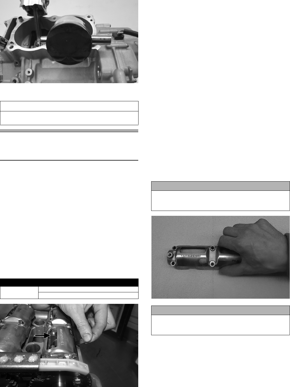
48
ROV1-044
16. Repeat step 15 for the other piston.
Servicing Top-Side
Components
MEASURING VALVE/TAPPET
CLEARENCE
1. Rotate the engine two full revolutions.
NOTE: Rotating the engine two full revolutions will
ensure that any oil trapped in the tappet/shim is
purged to maintain an accurate clearance reading.
2. Rotate the engine until the camshaft lobe of the valve
being measured is directly away from the tappet.
3. Using an appropriate thickness gauge, measure and
record the intake and exhaust valve clearance of the
cylinder that is on the compression stroke; then rotate
the engine 360° and measure and record the valve
clearance of the other cylinder. Valve clearance must
be within specifications.
KC534A
4. To select the correct replacement shim for an out-of-
specification clearance, note the three-digit number on
the surface of the existing shim; then refer to the
appropriate Tappet Shim Selection Table (Exhaust or
Intake) on the following pages and use this procedure:
A. Find the Measured Tappet Clearance (from step 3)
in the left-side vertical column of the table.
B. Find the Present Shim Size (three-digit-number) at
the top-side horizontal column of the table.
C. Match the clearance in the vertical column with the
present shim size to obtain the recommended
replacement shim.
Cleaning/Inspecting Valve Cover
NOTE: If the valve cover cannot be trued, the cylin-
der head assembly must be replaced.
1. Wash the camshaft holder in parts-cleaning solvent.
2. Place the camshaft holder on the Surface Plate cov-
ered with #400 grit wet-or-dry sandpaper. Using light
pressure, move the camshaft holder in a figure eight
motion. Inspect the sealing surface for any indication
of high spots. A high spot can be noted by a bright
metallic finish. Correct any high spots before assem-
bly by continuing to move the camshaft holder in a
figure eight motion until a uniform bright metallic fin-
ish is attained.
WT581
VALVE ASSEMBLY
When servicing valve assembly, inspect valve seats, valve
stems, valve faces, and valve stem ends for pits, burn
marks, or other signs of abnormal wear.
NOTE: Whenever a valve is out of tolerance, it must
be replaced.
AT THIS POINT
To service center crankcase components only, proceed
to Removing Left-Side Components.
Valve Clearance (Cold)
15°-25° C
(59°-77° F)
Intake: 0.16 mm (0.006 in.)
Exhaust: 0.22 mm (0.009 in.)
CAUTION
Do not remove an excessive amount of the sealing sur-
face or damage to the camshaft will result. Always check
camshaft clearance when resurfacing the valve cover.
CAUTION
Water or parts-cleaning solvent must be used in con-
junction with the wet-or-dry sandpaper or damage to
the sealing surface may result.
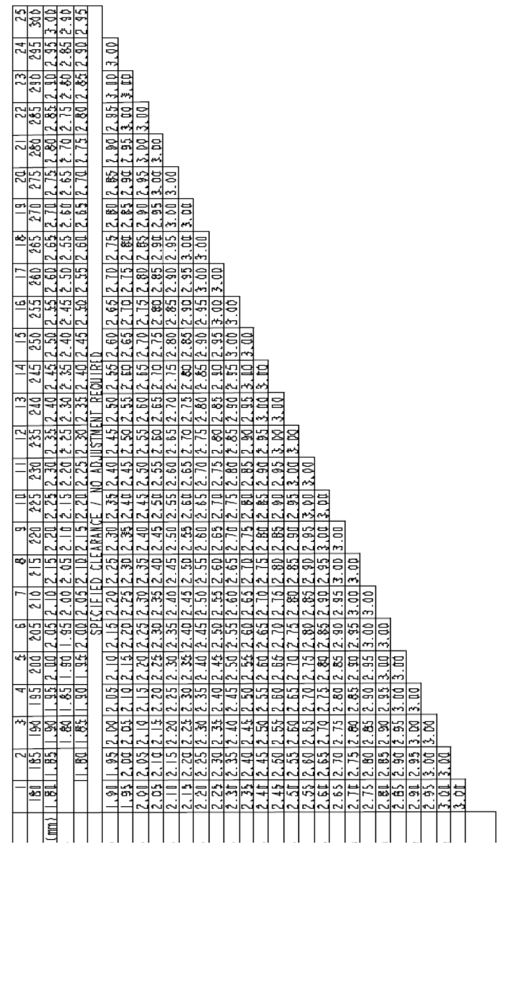
49
KCINTAKE
TAPPET CLEARANCE TABLE -
INTAKE
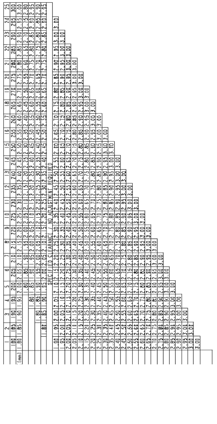
50
KCEXHAUST
TAPPET CLEARANCE TABLE -
EXHAUST
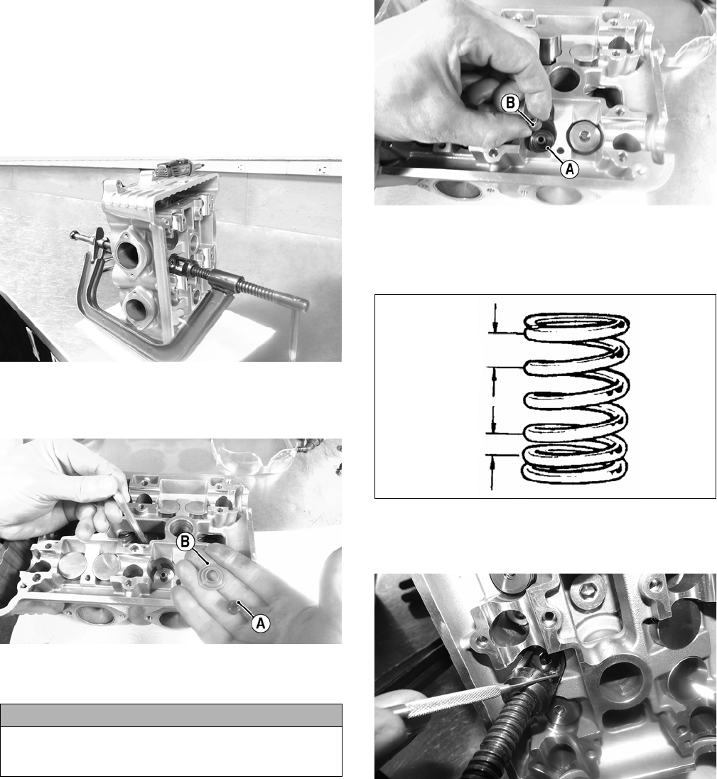
51
Removing Valves
NOTE: Index all valves, springs, and cotters to their
original position when removing. When installing, all
valve components should be installed in their origi-
nal position.
1. Using a valve spring compressor, compress the valve
springs and remove the valve cotters. Account for an
upper spring retainer.
WT585
2. Using an appropriate tool, remove the valve seal (A)
and the lower remaining spring seat (B). Discard the
valve seal.
WT583A
3. Remove the valve springs; then invert the cylinder
head and remove the valves.
Measuring Valve Guide (Bore)
1. Insert a suitable bore gauge 1/2 way into each valve
guide bore and record the measurement.
2. Acceptable inside diameter range must be within
specifications.
3. If a valve guide is out of tolerance, the cylinder head must
be replaced.
Installing Valves
1. Apply grease to the inside surface of new valve
seals; then place a lower spring seat (A) and valve
guide seal (B) over each valve guide.
WT582A
2. Insert each valve into its original location.
3. Install each valve spring (two per valve) with the closest
wound coils towards the cylinder head (down).
KC522
4. Place a spring retainer over the valve springs; then
using the valve spring compressor, compress the valve
springs and install the valve cotters (two per valve).
WT587
NOTE: Apply a small amount of grease to the end of
the tool to hold the cotter.
PISTON ASSEMBLY
NOTE: Whenever a piston or pin is out of tolerance,
it must be replaced.
Removing Piston Rings
1. Starting with the top ring, slide one end of the ring out
of the ring-groove.
2. Remove each ring by working it toward the dome of
the piston while rotating it out of the groove.
CAUTION
If valves are discolored or pitted or if the seating sur-
face is worn, the valve must be replaced. Do not attempt
to grind the valves or severe engine damage may occur.
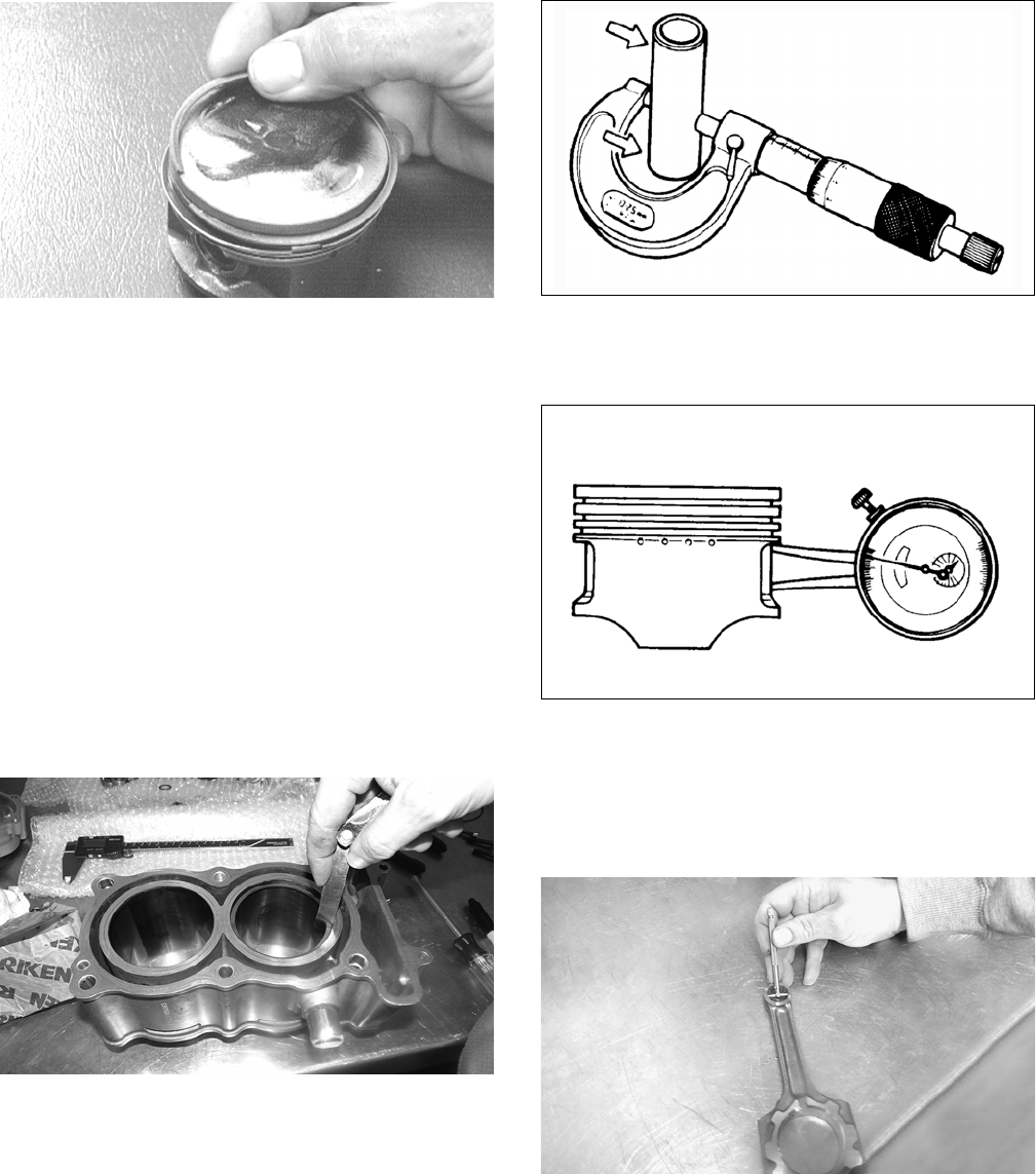
52
CC400D
Inspecting Piston
1. Inspect the piston for cracks in the piston pin, dome,
and skirt areas.
2. Inspect the piston for seizure marks or scuffing. If
observed, replace the piston.
3. Inspect the perimeter of each piston for signs of exces-
sive “blowby.” Excessive “blowby” indicates worn
piston rings or an out-of-round cylinder.
Measuring Piston-Ring End Gap
(Installed)
1. Place each compression ring in the wear portion of the
cylinder. Use the piston to position each ring squarely in
the cylinder.
2. Using a feeler gauge, measure each piston-ring end gap.
Ring end gap must not exceed 0.65 mm (1st/2nd) or 0.85
mm (oil).
WT586
Measuring Piston Pin (Outside
Diameter) and Piston Pin Bore
1. Measure the piston pin outside diameter at each end
and in the center. If measurement is less than 17.894
mm, the piston pin must be replaced.
ATV-1070
2. Insert an inside dial indicator into the piston pin bore.
The diameter must not exceed 18.018 mm. Take two
measurements to ensure accuracy.
ATV-1069
Measuring Connecting Rod
(Small End Bore)
1. Insert a snap gauge into the upper connecting rod
small end bore; then remove the gauge and measure it
with micrometer.
KC544
2. Maximum diameter must not exceed 18.044 mm. If
the diameter exceeds specification, the connecting rod
must be replaced (see Bottom Side Components in
this section).
Measuring Piston/Cylinder
Clearance
1. Measure the cylinder front to back in six places.
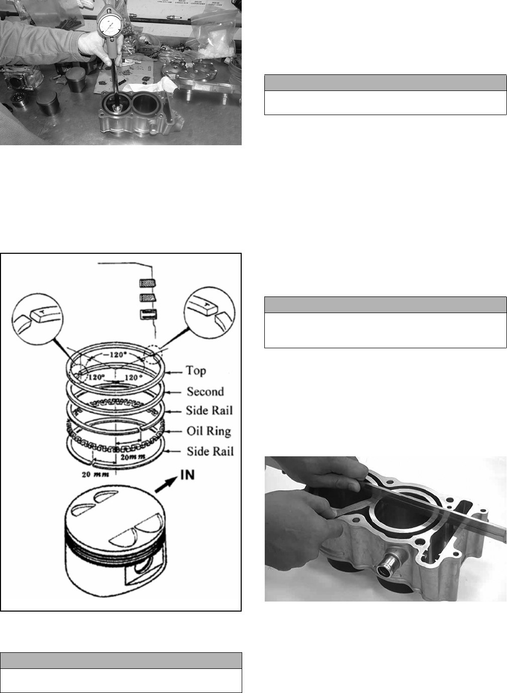
53
WT589
2. Measure the corresponding piston diameter at a point
10 mm above the piston skirt at a right angle to the
piston-pin bore. Subtract this measurement from the
measurement in step 1. The difference (clearance)
must not exceed 0.14 mm.
Installing Piston Rings
1. Install the rings (as shown).
KC700RINGS
2. Rotate the rings so the ring gaps are orientated as
shown and oriented to the piston pin.
CYLINDER/CYLINDER HEAD
ASSEMBLY
NOTE: If the cylinder/cylinder head cannot be trued,
they must be replaced as an assembly.
Cleaning/Inspecting Cylinder Head
1. Using a non-metallic carbon removal tool, remove any
carbon buildup from the combustion chamber being
careful not to nick, scrape, or damage the combustion
chamber or the sealing surface.
2. Inspect the spark plug hole for any damaged threads.
Repair damaged threads using a “heli-coil” insert.
3. Place the cylinder head on the surface plate covered
with #400 grit wet-or-dry sandpaper. Using light pres-
sure, move the cylinder head in a figure eight motion.
Inspect the sealing surface for any indication of high
spots. A high spot can be noted by a bright metallic
finish. Correct any high spots before assembly by con-
tinuing to move the cylinder head in a figure eight
motion until a uniform bright metallic finish is
attained.
Measuring Cylinder Head Distortion
1. Remove any carbon buildup in the combustion cham-
ber.
2. Lay a straightedge across the cylinder head; then
using a feeler gauge, check the distortion between the
head and the straightedge.
3. Maximum distortion must not exceed 0.05 mm.
KC523
Cleaning/Inspecting Cylinder
1. Wash the cylinder in parts-cleaning solvent.
2. Inspect the cylinder for pitting, scoring, scuffing,
warpage, and corrosion. If marks are found, repair the
surface using a cylinder hone (see Inspecting Cylinder
in this sub-section).
CAUTION
Incorrect installation of the piston rings will result in
engine damage.
CAUTION
The cylinder head studs must be removed for this pro-
cedure.
CAUTION
Water or parts-cleaning solvent must be used in con-
junction with the wet-or-dry sandpaper or damage to
the sealing surface may result.
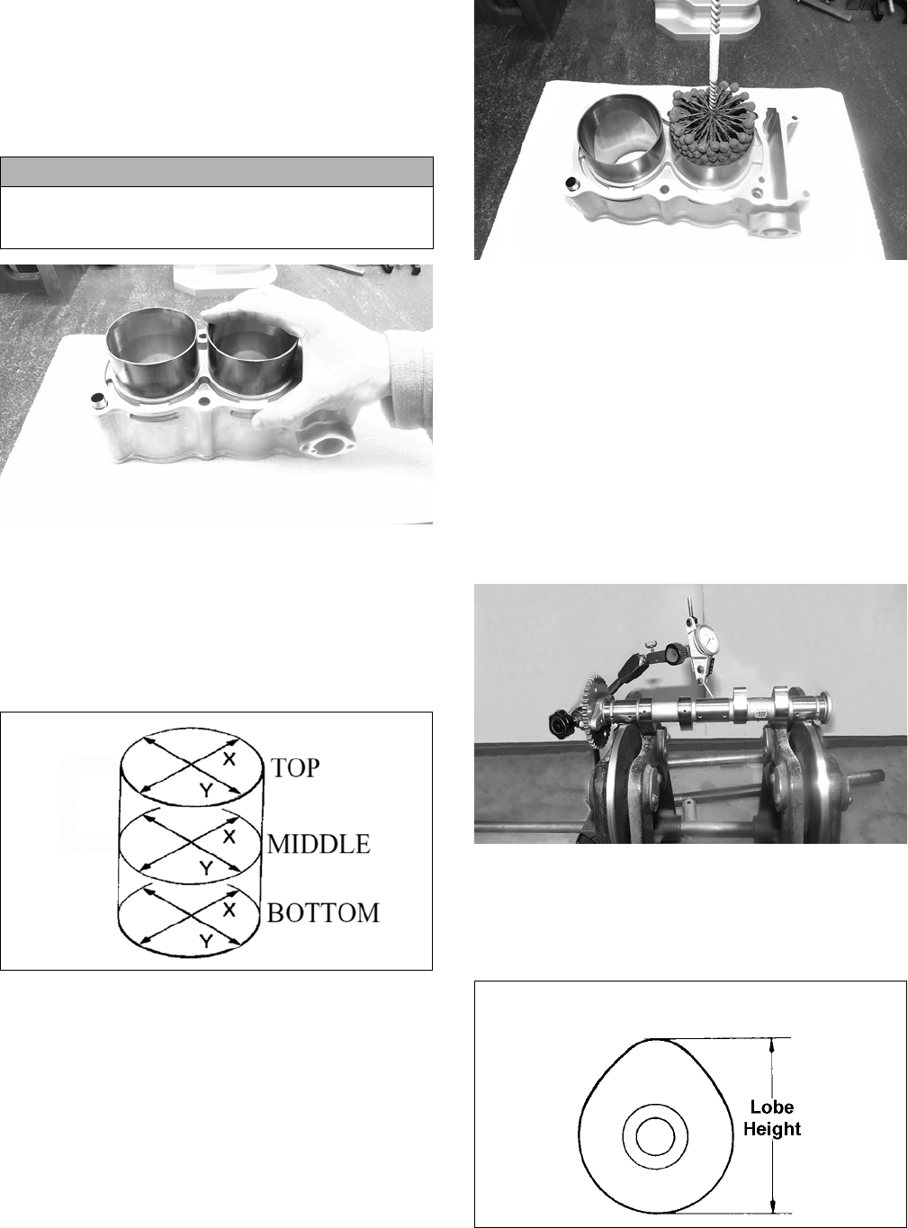
54
3. Place the cylinder on the surface plate covered with
#400 grit wet-or-dry sandpaper. Using light pressure,
move the cylinder in a figure eight motion. Inspect the
sealing surface for any indication of high spots. A
high spot can be noted by a bright metallic finish. Cor-
rect any high spots before assembly by continuing to
move the cylinder in a figure eight motion until a uni-
form bright metallic finish is attained.
WT580
4. Using a slide gauge and a dial indicator or a snap gauge,
measure the cylinder bore diameter in three locations
from top to bottom and again from top to bottom at 90°
from the first measurements for a total of six measure-
ments. The trueness (out-of-roundness) is the difference
between the highest and lowest reading. Maximum true-
ness (out-of-roundness) must not exceed 0.1 mm. Cylin-
der bore must not exceed 76.965 mm.
KC524
5. Wash the cylinder in parts-cleaning solvent.
6. Inspect the cylinder for pitting, scoring, scuffing, and
corrosion. If marks are found, repair the surface using
a #320 grit ball hone.
NOTE: To produce the proper 60° cross-hatch pat-
tern, use a low RPM drill (600 RPM) at the rate of 30
strokes per minute. If honing oil is not available, use
a lightweight petroleum-based oil. Thoroughly clean
cylinder after honing using soap and hot water. Dry
with compressed air; then immediately apply oil to
the cylinder bore. If the bore is severely damaged or
gouged, replace the cylinder.
WT579
7. If any measurement exceeds the limit, replace the cyl-
inder and piston.
Inspecting Cam Chain Guide
1. Inspect cam chain guide for cuts, tears, breaks, or chips.
2. If the chain guide is damaged, it must be replaced.
Measuring Camshaft Runout
NOTE: If the camshaft is out of tolerance, it must be
replaced.
1. Place the camshaft on a set of V blocks; then position
the dial indicator contact point against the shaft and
zero the indicator.
KC526
2. Rotate the camshaft and note runout; maximum run-
out must not exceed 0.05 mm.
Measuring Camshaft Lobe Height
1. Using a calipers, measure each cam lobe height.
ATV1013A
2. The lobe heights must be greater than 36.6 mm.
CAUTION
Water or parts-cleaning solvent must be used in con-
junction with the wet-or-dry sandpaper or damage to
the sealing surface may result.
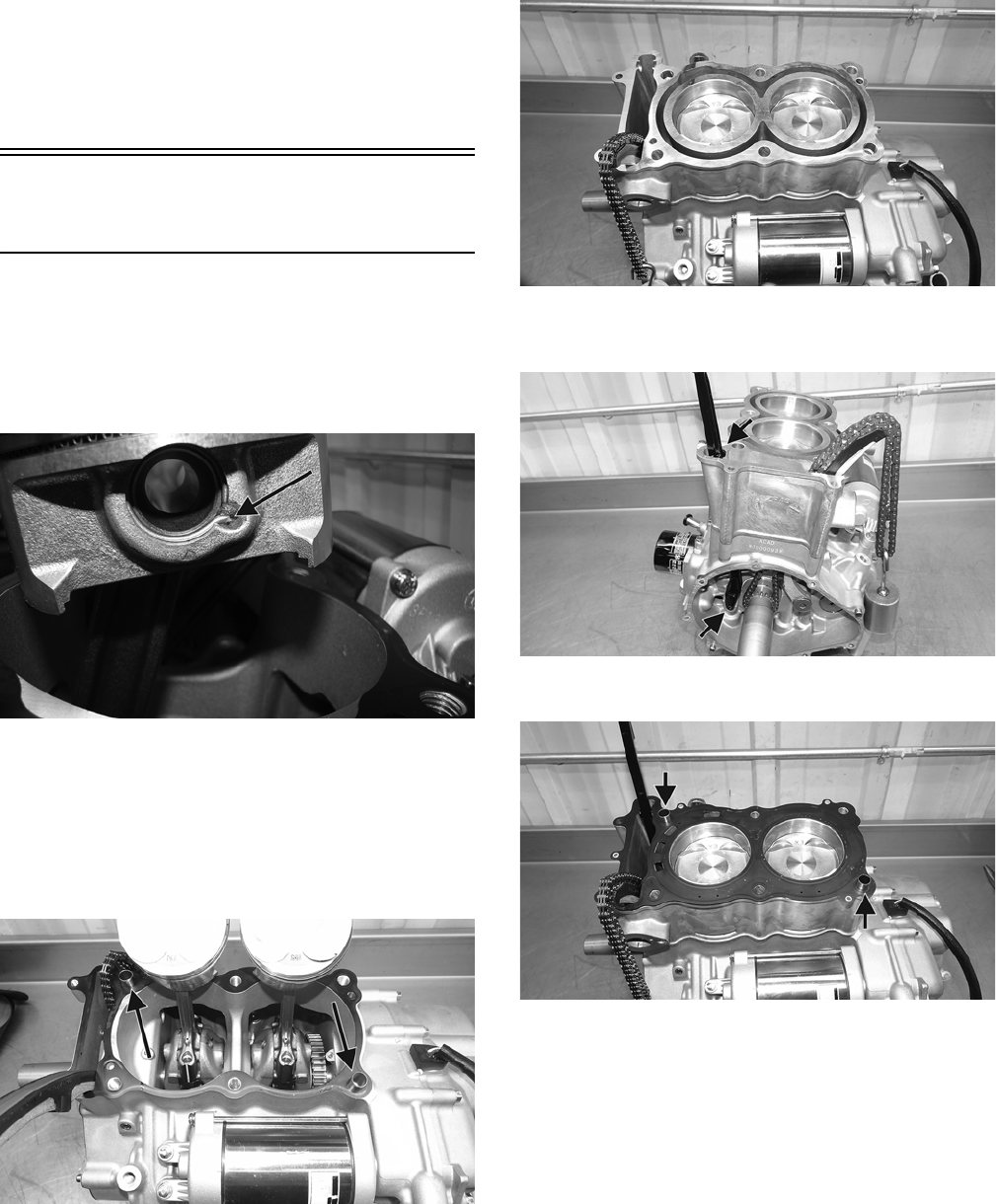
55
Inspecting Camshaft Bearing
Journal
1. Inspect the bearing journal for scoring, seizure marks,
or pitting.
2. If excessive scoring, seizure marks, or pitting is found,
the cylinder head assembly must be replaced.
NOTE: If the journals are worn, replace the camshaft.
Installing Top-Side
Components
NOTE: Arctic Cat recommends new gaskets be
used when assembling the engine.
1. Before installing on the connecting rod, install the
inside piston circlip into the piston making sure the
open end curve is in the piston opening.
WT129A
2. Install the piston on the connecting rod making sure
the “IN” is facing the intake side of the engine and
slide the piston pin through the piston; then install
the other piston circlip.
3. Repeat steps 1 and 2 for the other piston.
4. Install a new base gasket and the two dowel pins.
WT130A
5. Apply a generous amount of lubricant to both of the pis-
tons and the inside of the cylinders.
6. Using an appropriate ring compressor, compress the
rings and slide the cylinder over the pistons.
7. Pull the chain up through the cylinder and slide the cylin-
der down onto the dowel pins.
WT131
8. Install the chain guide so it is seated at the top and
bottom.
WT132A
9. Install the two dowel pins and a new head gasket.
WT133A
10. While pulling the chain up through the head, install the
head onto the cylinder accounting for the chain guide,
chain tensioner guide, and two dowel pins.
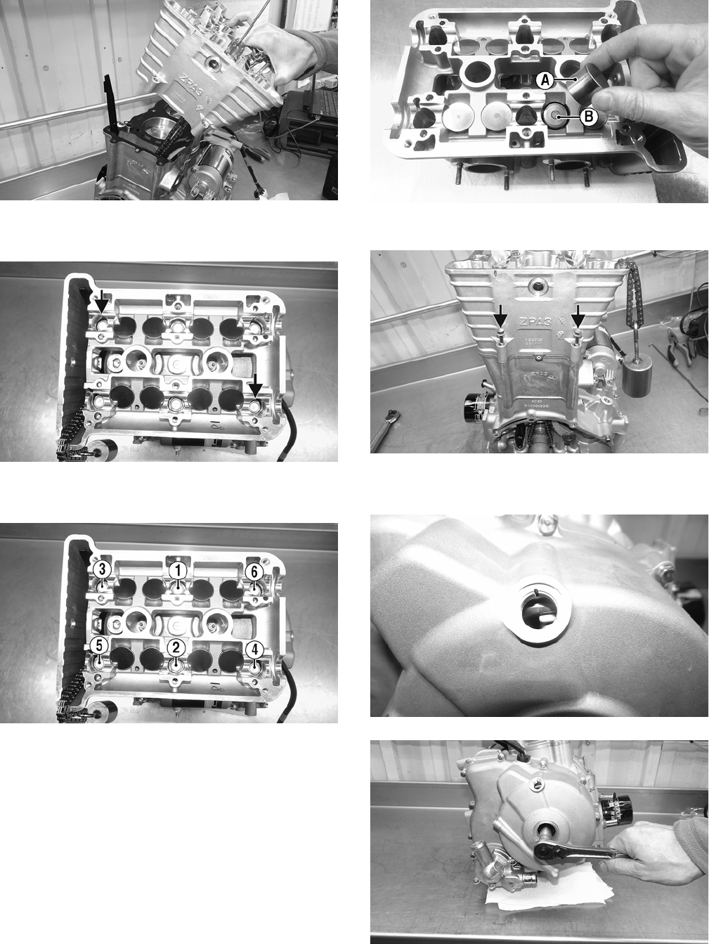
56
WT134
11. Install the cap screws (threads coated with oil) with the
two longer bolts going in the dowel pin locations.
WT142A
12. In the order shown, tighten the head bolts to 22 ft-lb,
then to 29 ft-lb, and finally to 36 ft-lb.
WT142B
NOTE: Care must be taken not to damage the cam
shaft journals while tightening the head bolts.
13. With a light film of engine-assembly grease applied
to the tappets, install the correct shim (B) and tappet
(A) to each valve of the cylinder head as noted dur-
ing disassembling.
WT471A
14. Install the two outside fasteners and tighten to 7 ft-lb.
WT143A
15. Making sure the chain stays on the crankshaft
sprocket, rotate the engine to TDC.
WT145
WT144
16. Install the exhaust cam shaft; then install the chain
around the sprocket so the exhaust timing mark is
parallel with the head surface.
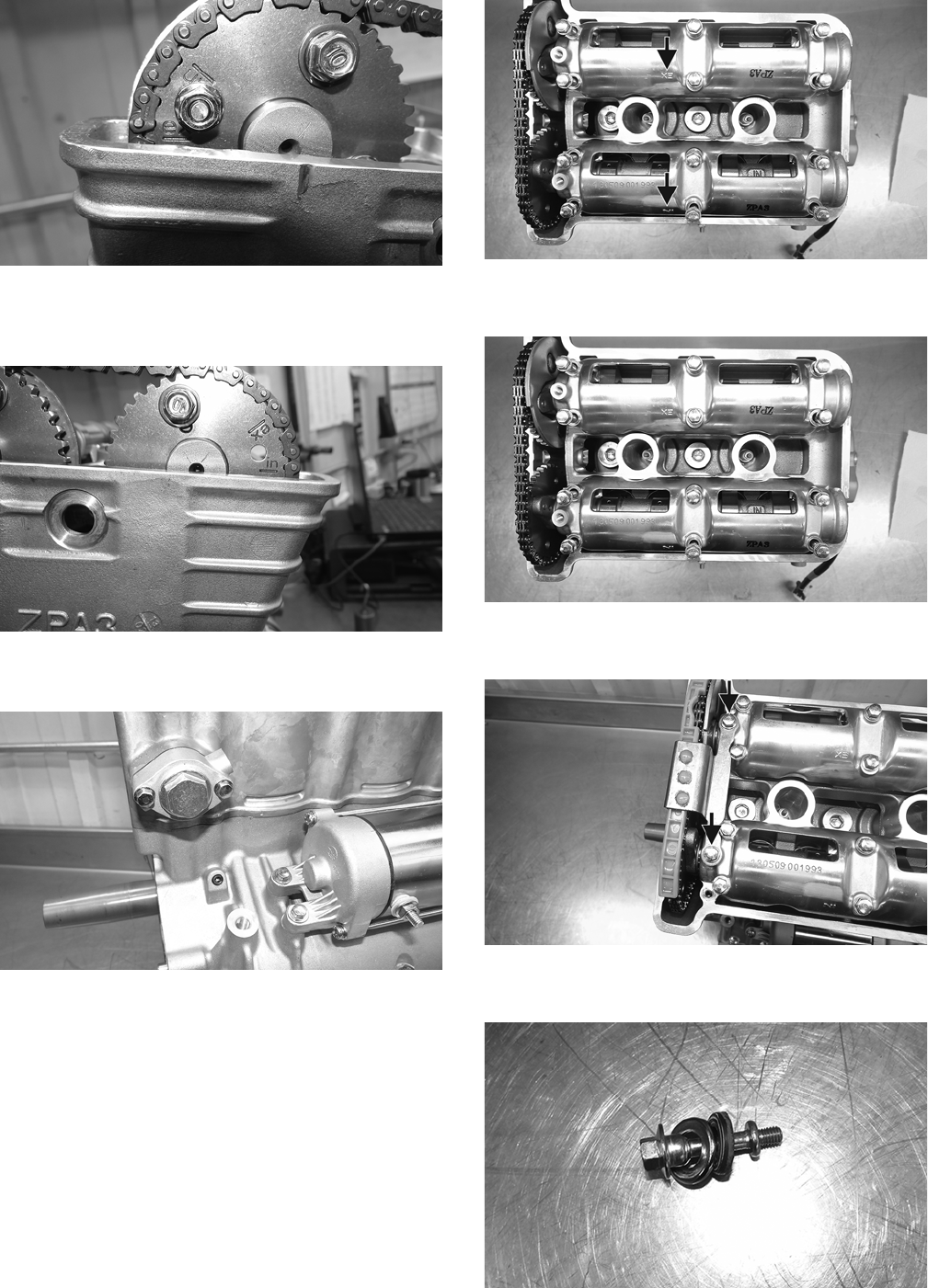
57
WT147
17. Install the intake cam shaft; then install the chain
around the sprocket so the intake timing mark is par-
allel with the head surface.
WT151
18. Install the cam chain tensioner and tighten the cap
screws to 15 ft-lb.
WT153
19. With the engine at TDC and each cam timing mark
properly aligned, place each camshaft holder on the
proper camshaft.
NOTE: Each holder has an “In” and “Ex”.
WT156A
20. Install the fasteners and in the order shown, tighten to
7 ft-lb.
WT156
21. Install the upper chain guide and tighten the fasteners
to 7 ft-lb.
WT159
22. Install the head wall fastener with the rubber washer
and steel cup.
WT160
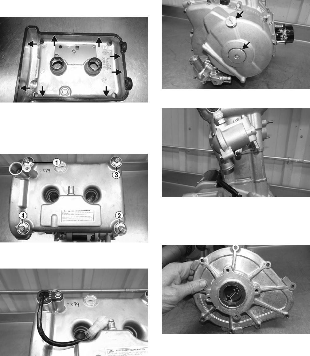
58
23. Install the rubber gasket onto the head cover and
install onto the head.
WT162A
NOTE: Applying a small bead of silicone between the
head cover and rubber gasket will aid in assembling.
24. Tighten the head cover fasteners in the order shown to
7 ft-lb with the rubber washers and steel cups.
WT163A
25. Install the cam timing sensor with O-ring (lightly
coated with grease).
WT165
26. Install the timing inspection and magneto plugs.
Tighten the timing inspection plug to 10 ft-lb and the
magneto plug to 11 ft-lb.
WT166A
27. Install the thermostat housing.
WT168
NOTE: Apply a small amount of grease to the O-ring
before installing.
28. With the seal coated in grease, slide the PTO-side
cover over the crankshaft (with the two dowel pins).
WT169A
29. Install the fasteners and tighten to 7 ft-lb.
NOTE: The two longer fasteners go in the dowel pin
locations.
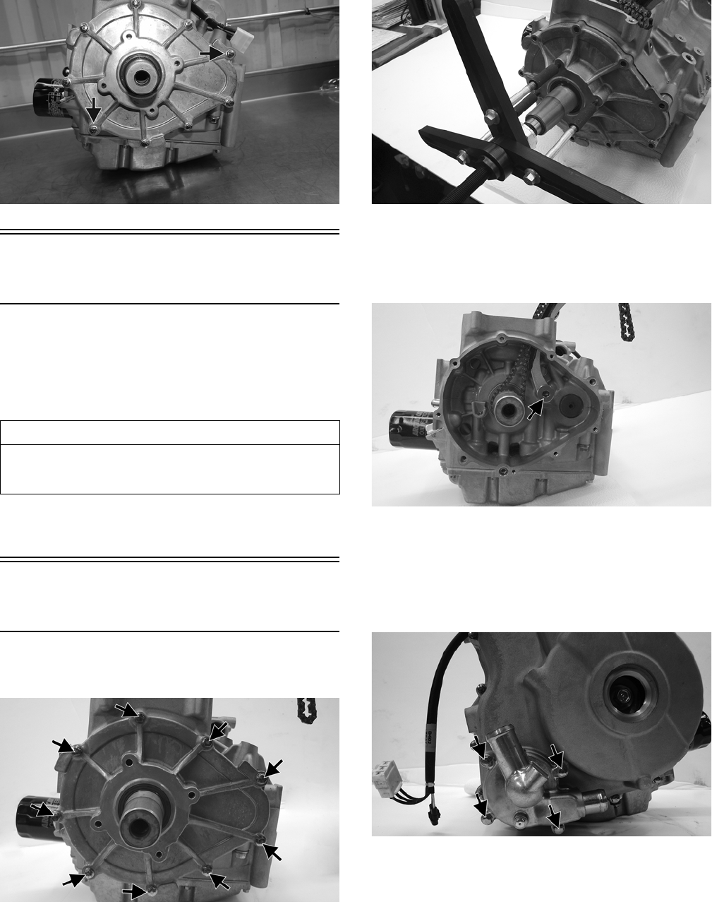
59
WT170A
Bottom-Side
Components
NOTE: For efficiency, it is preferable to remove and
disassemble only those components which need to
be addressed and to service only those components.
The technician should use discretion and sound
judgment.
NOTE: The engine must be removed from the frame
for this procedure.
Removing Bottom-Side
Components
1. Remove the cap screws securing the PTO-side cover
to crankcase.
ROV1-045A
2. Using an appropriate puller if needed, remove the
PTO-side cover. Account for a gasket, two dowel pins,
and two longer fasteners for assembly purposes.
ROV1-048
3. Remove the chain by pulling it down through the
crankcase and out the PTO side.
4. Remove the fastener securing the chain guide to the
crankcase.
ROV1-056A
NOTE: If the water pump does not require servicing,
it does not have to be removed.
5. Remove the cap screws securing the water pump
cover to the crankcase. Account for two dowel pins
and an O-ring.
ROV1-054A
6. Remove the cap screws securing the MAG-side cover
to the crankcase. Account for two dowel pins and dis-
card the gasket.
AT THIS POINT
To service any one specific component, only limited dis-
assembly of components may be necessary. Note the
AT THIS POINT information in each sub-section.
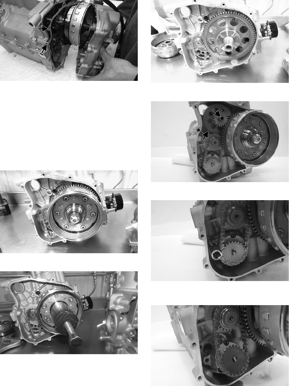
60
ROV1-108A
NOTE: Account for the different-lengthed fasteners
for assembling purposes.
NOTE: If the technician’s objective is to service or
replace the flywheel or starter gear, proceed to the
step 7; if not, continue to disassemble the bottom
side components without removing the flywheel or
starter gear.
7. Remove the cap screw securing the rotor/flywheel to
the crankshaft. Account for a washer and install the
crankshaft protector.
KC545
8. Using the flywheel puller, remove the flywheel.
KC546
9. Remove the starter gear leaving the flywheel key in
position.
KC543
10. Remove the starter idler gear and shaft.
ROV1-065A
11. Remove the two cap screws securing oil pump.
ROV1-063
12. Remove the oil pump leaving the chain on the top
sprocket. Account for two dowel pins and two O-rings.
ROV1-066
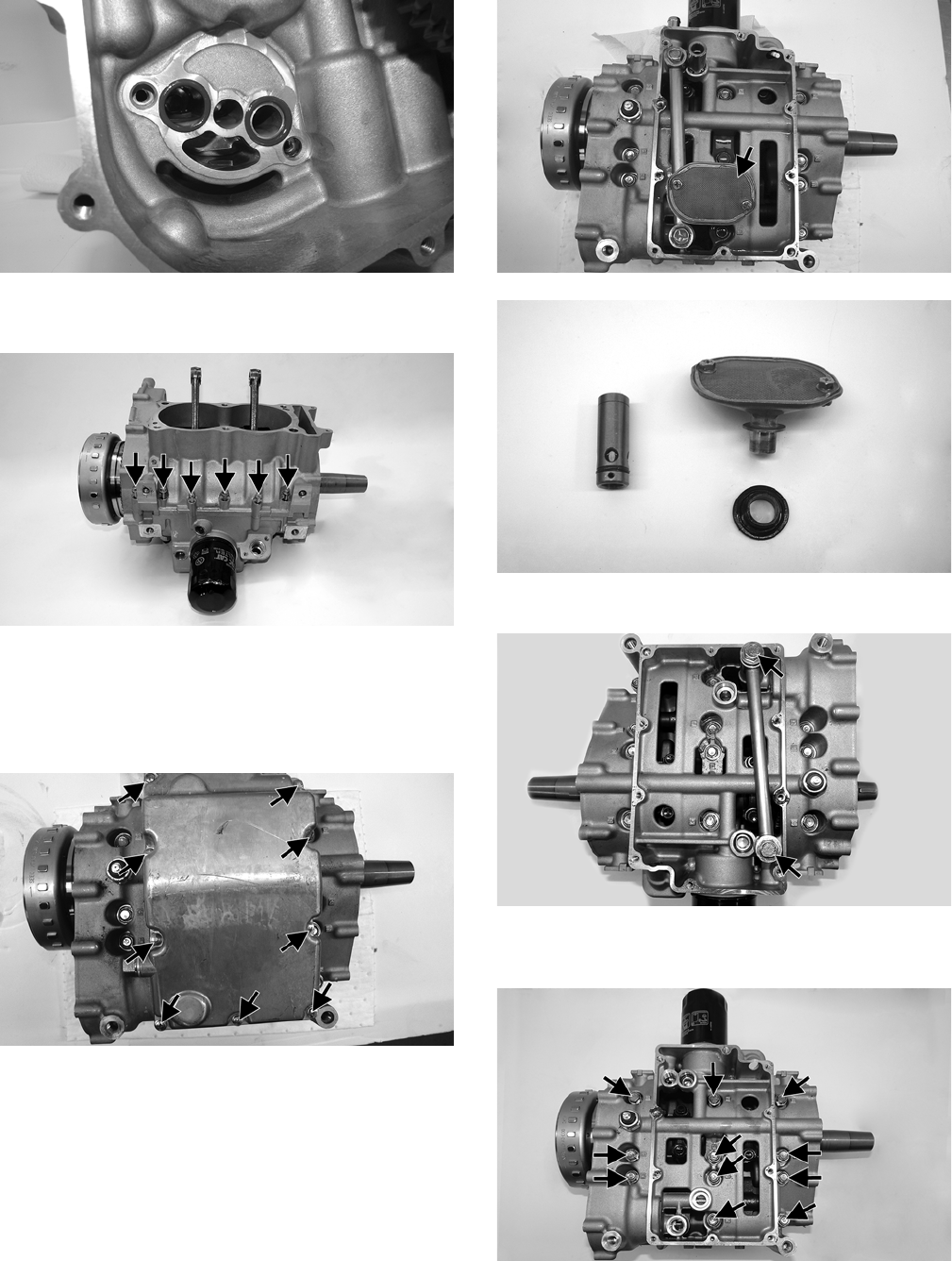
61
ROV1-064
13. Remove the fasteners connecting the top case half to
the bottom case half.
ROV1-077A
NOTE; The fastener just above the oil filter is longer
than the others.
14. Rotate the engine and remove the cap screws securing
the oil pan to the crankcase.
ROV1-069A
15. Remove the oil pan and account for two dowel pins
and a gasket.
NOTE: Using a rubber mallet will aid in the removal
of the oil pan.
16. Remove the oil pressure relief and oil screen. Account
for a rubber seal under the oil pressure relief valve.
ROV1-070A
ROV1-068
17. Remove the oil passage tube and oil level stick.
ROV1-092A
18. Remove the fasteners and washers securing the bot-
tom case half to the top case half.
ROV1-078A
NOTE: Bolts 1-6 are longer than the other fasteners.
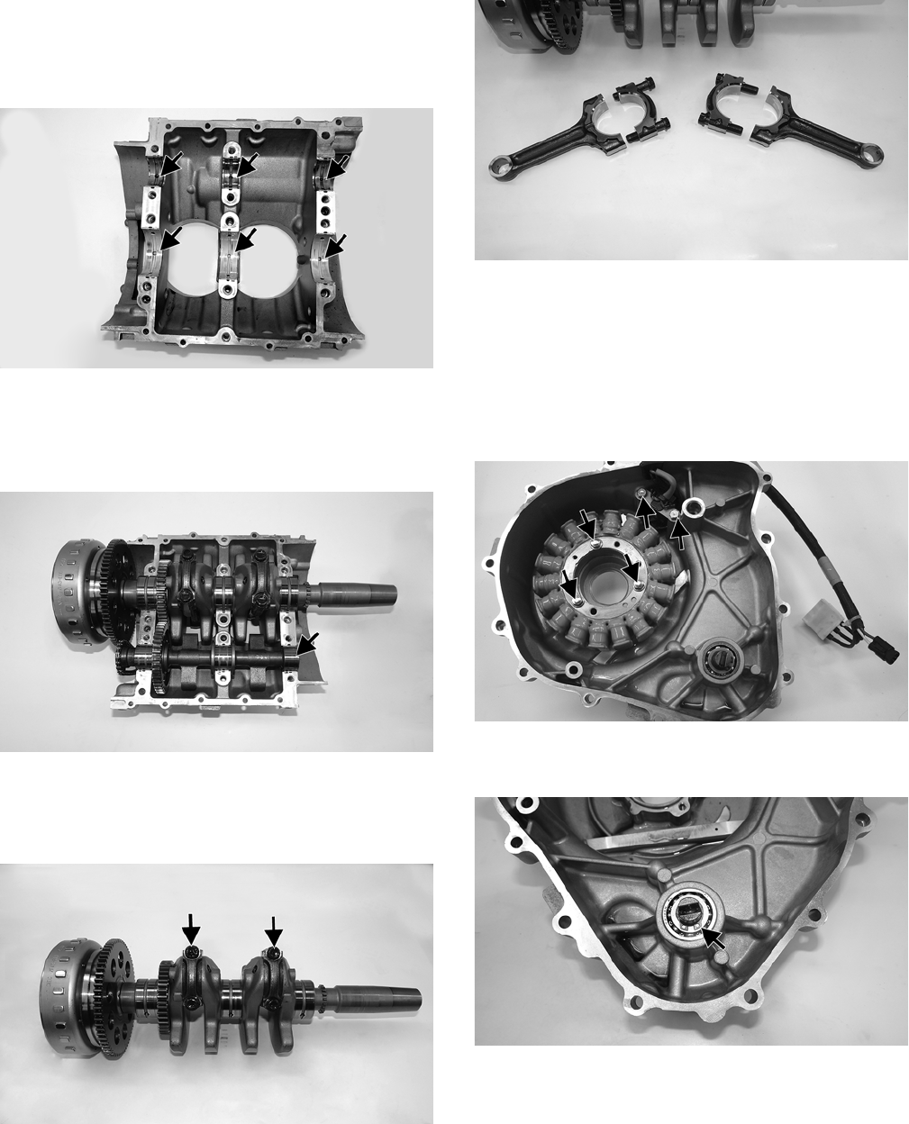
62
19. Pull the case halves apart and note the six plain bear-
ings in each case half.
NOTE: Using a rubber mallet will aid in separating
the case halves.
ROV1-088A
NOTE: Note the color coding on the bearings for
assembling purposes.
20. Remove the counterbalance shaft from the case.
ROV1-080A
21. Remove the crankshaft from the case.
22. Remove the cap screws securing the connecting rods
together.
ROV1-083A
ROV1-084
NOTE: Note the color coding on the bearings for
assembling purposes.
NOTE: Keep both the top and bottom of the con-
necting rod together as they are a matching set.
23. Remove the fasteners securing the stator and the crank-
shaft position sensor in place; then remove the stator.
ROV1-059A
24. Remove the retaining ring and washer securing the
water pump to the case.
ROV1-115A
25. Remove the impeller.
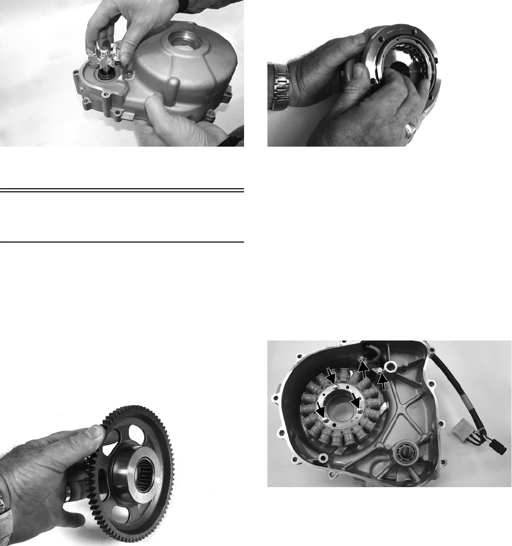
63
ROV1-111
26. Remove the mechanical seal from the cover and the
ceramic mating seal from the impeller.
Servicing Bottom-Side
Components
INSPECTING STARTER CLUTCH/
GEAR
1. Place the starter clutch gear onto the rotor/flywheel and
attempt to rotate the starter clutch gear clockwise. It
should lock up to the rotor/flywheel. Rotate the gear coun-
terclockwise and it should turn freely. If it moves or locks
up both ways, the starter clutch must be replaced.
2. Inspect the starter clutch gear for chipped or missing
teeth or discoloration/scoring of the clutch surface.
Inspect the bearing for loose, worn, or discolored roll-
ers. If bearing is damaged, the gear must be replaced.
FI569
3. Inspect the one-way bearing for chipped surfaces,
missing rollers, or discoloration. If any of the above
conditions exist, replace the starter clutch assembly.
FI572
INSPECTING STATOR COIL/
MAGNETO COVER ASSEMBLY
1. Inspect the stator coil for burned or discolored wiring,
broken or missing hold-down clips, or loose cap
screws.
2. Inspect the bearings in the magneto housing for dis-
coloration, roughness when rotated, and secure fit in
bearing bores.
REPLACING STATOR COIL/
CRANKSHAFT POSITION SENSOR
1. Remove the three cap screws securing the stator coil
and the two cap screws securing the crankshaft posi-
tion sensor.
ROV1-059A
2. Lift the rubber grommet out of the housing; then
remove the stator coil/crankshaft position sensor.
Account for and note the position of the harness hold-
down under the crankshaft position sensor.
3. Install the new stator coil assembly and secure with
three cap screws. Tighten the cap screws to 15 ft-lb.
4. Place the stator wire harness hold-down into position;
then install the crankshaft position sensor and secure
with two cap screws. Tighten securely.
CRANKSHAFT ASSEMBLY
Runout
1. Support the crankshaft using a set of V Blocks; use a
dial indicator to read crankshaft runout.
NOTE: The contact point of the dial indicator should
be on either side of the oil port hole of the center
crankshaft journal and to the outside of the oil port
hole on the MAG and PTO end of the crankshaft.
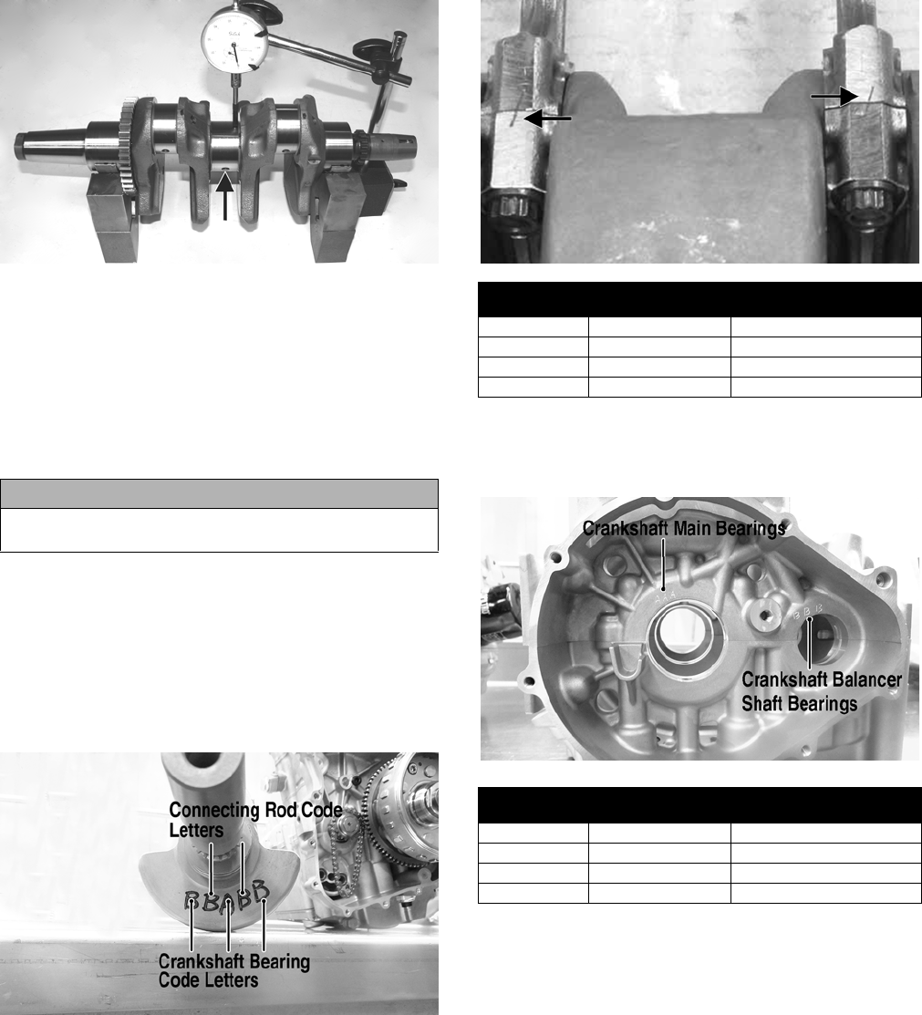
64
ZJ058A
2. Rotate the crankshaft slowly.
3. The reading must be 0.002 in. or crankshaft repair-
ing/replacing will be necessary.
Main Bearings
Check the main bearings for signs of pitting, scratches,
wear, or damage. If any of these conditions are found, the
bearings must be replaced.
Bearing Selection
NOTE: This information is needed only if the crank-
shaft or the engine cases have been replaced or if the
connecting rod and main bearings are out of specifi-
cations.
Select the proper bearing inserts for the replacement in
accordance with the crankshaft mark.
KC539A
The connecting rods go with a grade number mark. The
mark will be a number “1” or “2” located on the side sur-
face of rod as shown. Determine the replacement bearing
color by following the table.
KC527A
The crank cases go with a grade mark. The mark will be
“A” or “B” located on the side surface of the case as
shown. Determine the replacement bearing color by fol-
lowing the table.
KC538A
The crank balancer goes with a grade mark. The mark will
be “A” or “B” located on the balancer shaft as shown.
Determine the replacement bearing color by following the
table.
CAUTION
Always replace the bearings as a set; never replace one
side only or severe engine damage will occur
Crankshaft
Mark Connecting Rod
Mark Bearing Inserts Color
Choice
A1 Black
A2 Green
B1 Green
B2 Red
Crankshaft
Mark Crankcase Mark Bearing Inserts Color
Choice
AA Black
AB Green
BA Green
BB Red
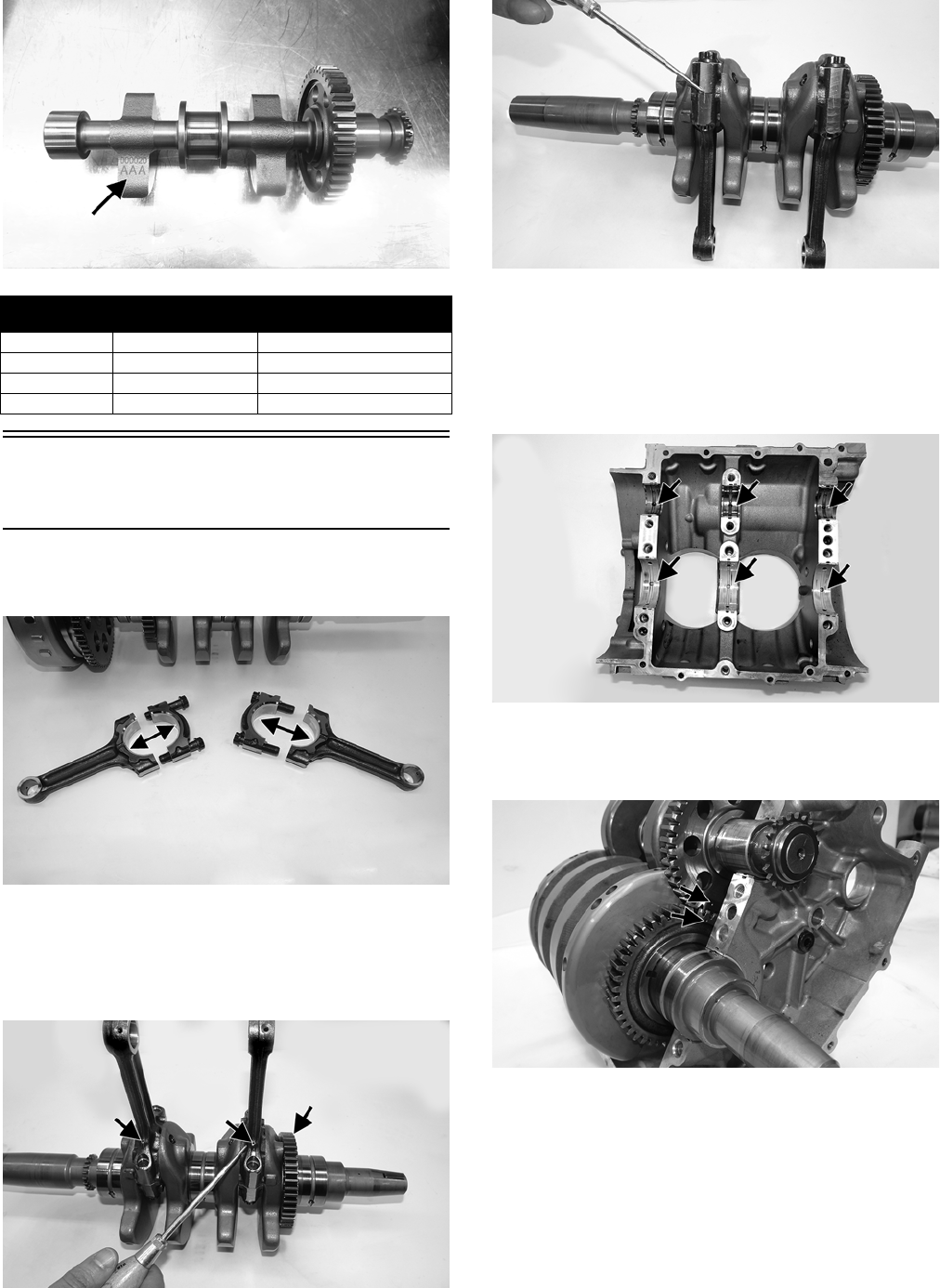
65
KC531A
Installing Bottom-Side
Components
1. Using a suitable assembly lubricant, lubricate all bear-
ing surfaces of the connecting rods.
ROV1-084A
2. Connect the mating halves of the connecting rod on
the crankshaft making sure the gear is on the right
hand side and the oil holes are facing the intake side.
Install the bolts (threads coated with oil); finger-
tighten only at this point.
ROV1-087A
ROV1-085
NOTE: It is critical to ensure the lines between the
two connecting rod halves match in a straight line.
3. In the top crankcase, apply a suitable assembly lubri-
cant to the six plain bearing tops and bottoms; then
carefully place the crankshaft into the crank case.
ROV1-088A
4. Place the counterbalance shaft into the case making
sure the alignment marks on the counterbalance gear
and crankshaft are aligned.
ROV1-089A
5. Wipe off the sides of the case half; then apply a bead
of high-temp silicone to the sides of the case half.
Balancer Shaft
Mark Crankcase Mark Bearing Inserts Color
Choice
AA Yellow
A B Green
B A Green
BB Brown
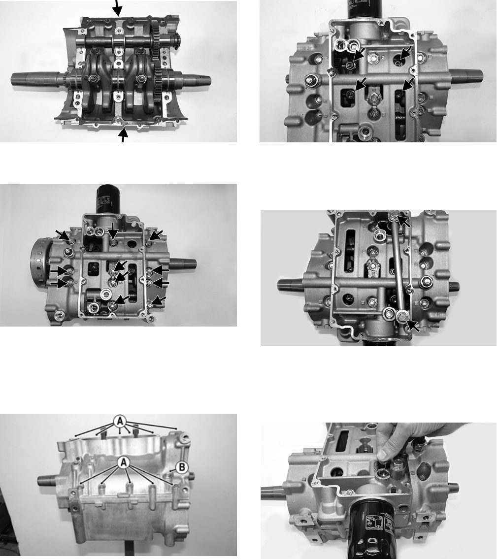
66
ROV1-090A
6. Install the bottom end of the crankcase and install the exist-
ing eleven cap screws and washers. Tighten to 21 ft-lb.
ROV1-078A
NOTE: The longer fasteners go in the holes num-
bered one through six.
7. Rotate the engine to right-side up and install the remaining
crankcase cap screws and washers. Tighten the cap screws
(A) to 8 ft-lb and the cap screw (B) to 21 ft-lb.
KC550A
NOTE: The longer bolt is installed just to the right of
the oil filter.
8. Rotate the engine again and using a twelve-point
socket, tighten the connecting rods to 22 ft-lb, then to
36 ft-lb, and finally to 45 ft-lb.
ROV1-091A
NOTE: Rotating the crankshaft will aid in lining up
the fasteners.
9. Install the oil crossover tube. Tighten to 13.5 ft-lb.
ROV1-092A
NOTE: Verify the correct positioning of the washers.
10. Place the rubber O-ring into the oil pressure relief valve
bore; then push the oil pressure relief valve until the O-
ring on the valve is past the chamfer.
ROV1-095
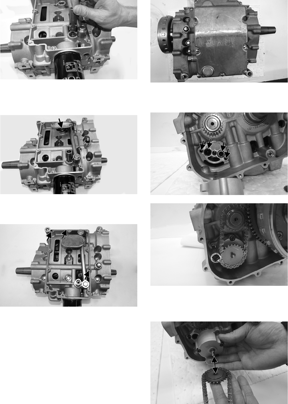
67
ROV1-096
11. Install the oil screen pickup grommet with the flat side of
the rubber facing up; then install the oil screen so the high
side faces the oil filter to make it level with the oil pan
when installed.
ROV1-099A
12. Using a gasket scraper, clean off the old gasket from
the oil pan and case. Install a new gasket and two
dowel pins.
ROV1-100A
NOTE: The two longer fasteners go in the dowel pin
locations.
13. Install the oil pan. Tighten the cap screws to 8 ft-lb.
ROV1-069
14. With t
he O-rings and dowel pins in the proper loca-
tions, install and secure
the oil pump with the appropri-
ate fasteners. Tighten to 8 ft-lb.
ROV1-101A
ROV1-063
NOTE: When installing the pump, the chain and
sprocket must be on the oil pump and counterbalance
shaft with the sprocket shoulder facing the oil pump.
ROV1-103A
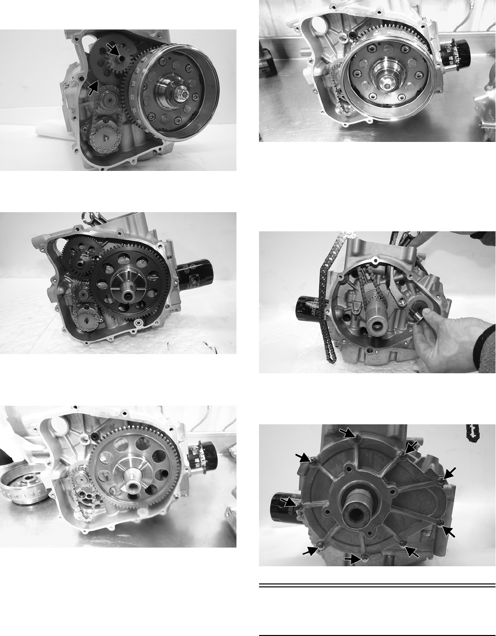
68
15. Install the starter idler gear and pin with the smaller
gear facing outward.
ROV1-065A
16. Install the starter gear on the crankshaft with the
shoulder facing outwards.
ROV1-105
17. If the flywheel and starter gear were removed, install
the starter gear onto the crankshaft; then install the
flywheel key.
KC543
NOTE: Be sure to wipe any grease or oil from the
end of the crankshaft.
18. Install the flywheel onto the crankshaft and secure
with the cap screw. Tighten to 60 ft-lb.
KC545
19. Using a gasket scraper, clean off the existing gasket
and case from the MAG cover. Using a new gasket
and dowel pins, install the cover making sure the cool-
ant pump shaft is aligned with the oil pump shaft.
Tighten to 7 ft-lb.
20. Install the chain guide and secure with the fastener.
ROV1-107
21. With two dowel pins and the gasket in place, install
the PTO-side cover onto the crankcase and tighten to 7
ft-lb.
ROV1-045A
Servicing Left-Side
Components
NOTE: The engine does not have to be removed
from the frame for this procedure.
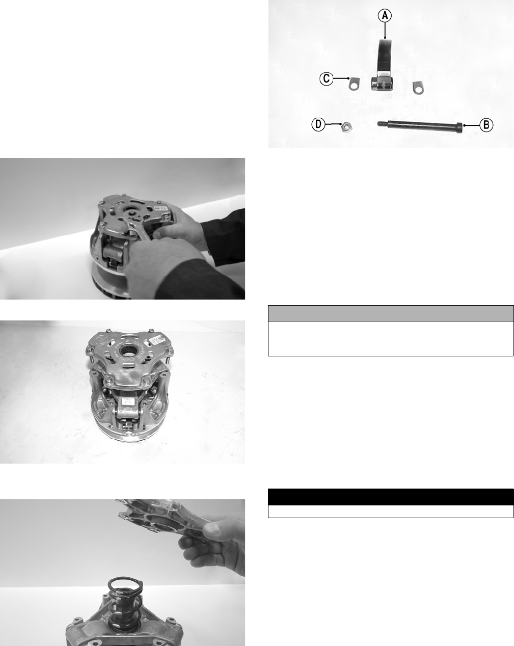
69
NOTE: To remove left-side components, see Engine
- Removing Engine.
DRIVE CLUTCH
Disassembling
NOTE: Note the timing marks (X) on the cover, spider,
and movable sheave. These must be aligned when
assembling the drive clutch for balance purposes.
1. Loosen the machine screws securing the cover.
Remove every other cap screw from the cover; then
while firmly holding the cover, remove the three
remaining screws equally.
WC659
WT519
2. Remove the cover and spring.
WC657
3. Remove the lock nuts (D) from the cam arm pivot pins
(B); then remove the pins and account for six thrust
washers (C) and three cam arms (A).
WT518A
Cleaning and Inspecting
NOTE: If any components other than flyweights, pins,
spring, thrust washers, or cover are damaged or worn,
clutch replacement is necessary.
1. Using parts-cleaning solvent, wash grease, dirt, and
foreign matter off all components; dry with com-
pressed air.
2. Remove any drive belt dust accumulation from the
stationary sheave, movable sheave, and bushings
using parts-cleaning solvent only.
3. Inspect the cover for cracks or imperfections in the
casting.
4. Inspect the cam arm pins for wear or bends.
5. Inspect the bushing in the cover for wear, damage, or
cracks.
6. Inspect the spring for cracking or twisting.
7. Inspect the cam arms for grooves.
Assembling
1. Place the cam arms, thrust washers, and cam arm
pivot pins (pivot pin heads with the direction of rota-
tion) into the moveable drive sheave and secure with
new lock nuts. Tighten to 48 in.-lb.
NOTE: The drive clutch rotates counterclockwise.
CAUTION
Do not use steel wool or a wire brush to clean compo-
nents having a bushing; damage to the bushing will
result.
! WARNING
Never reuse the lock nuts on the cam arm pins.
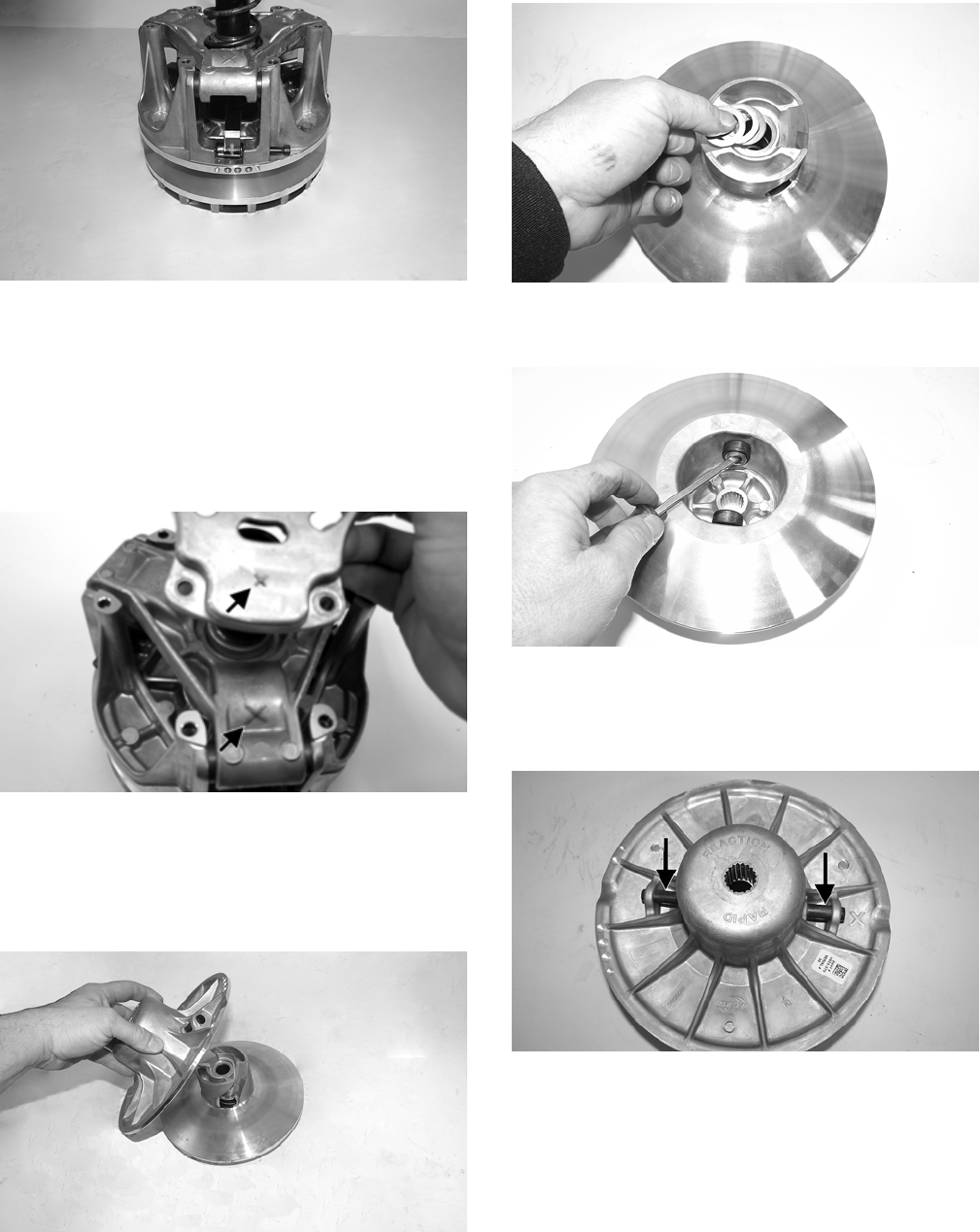
70
WT521
NOTE: Grasp the moveable sheave and lift it
upward; then release it. It must move freely and not
bind at any point.
2. Install the spring.
3. Align the match marks (X) and install the clutch cover
and secure with six cap screws. Tighten using a criss-
cross pattern to 120 in.-lb.
WC653A
DRIVEN CLUTCH
Disassembling
1. Remove the stationary sheave from the movable
sheave. Account for the shims.
WT526
WT191
2. In the stationary sheave using a suitable tool, remove
the E-clips securing the rollers.
WT197
NOTE: The roller pins are not a serviceable item. If
they are damaged in any way, the stationary sheave
must be replaced.
WT193A
3. Place the moveable sheave in an appropriate driven
clutch compression tool. Finger-tighten the wing nut
and remove the spring retaining plate.
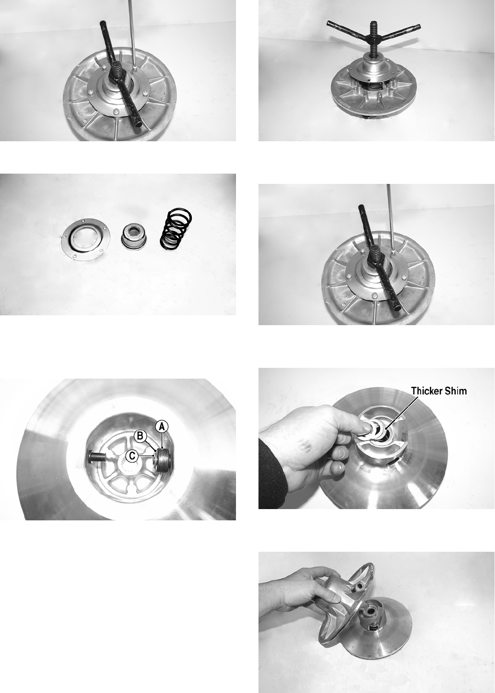
71
WT189
4. Remove the spring retaining plate cup and spring.
WT523
Assembling
1. Install the roller (A) and flat washer (B); then secure
with the E-clip (C) on the roller pin.
WT198A
2. Install the spring (A), the cup (B), and the spring
retaining plate (C) in the moveable sheave; then place
in a suitable driven clutch compression tool and fin-
ger-tighten the wing nut.
WT527
3. Secure the spring retaining plate with the existing cap
screws and tighten it to 11 ft-lb.
WT189
4. Put shims in the movable sheave with the thicker shim
towards the movable sheave.
WT191A
5. Place the stationary sheave in the movable sheave
making sure the “X” timing marks are aligned.
WT526
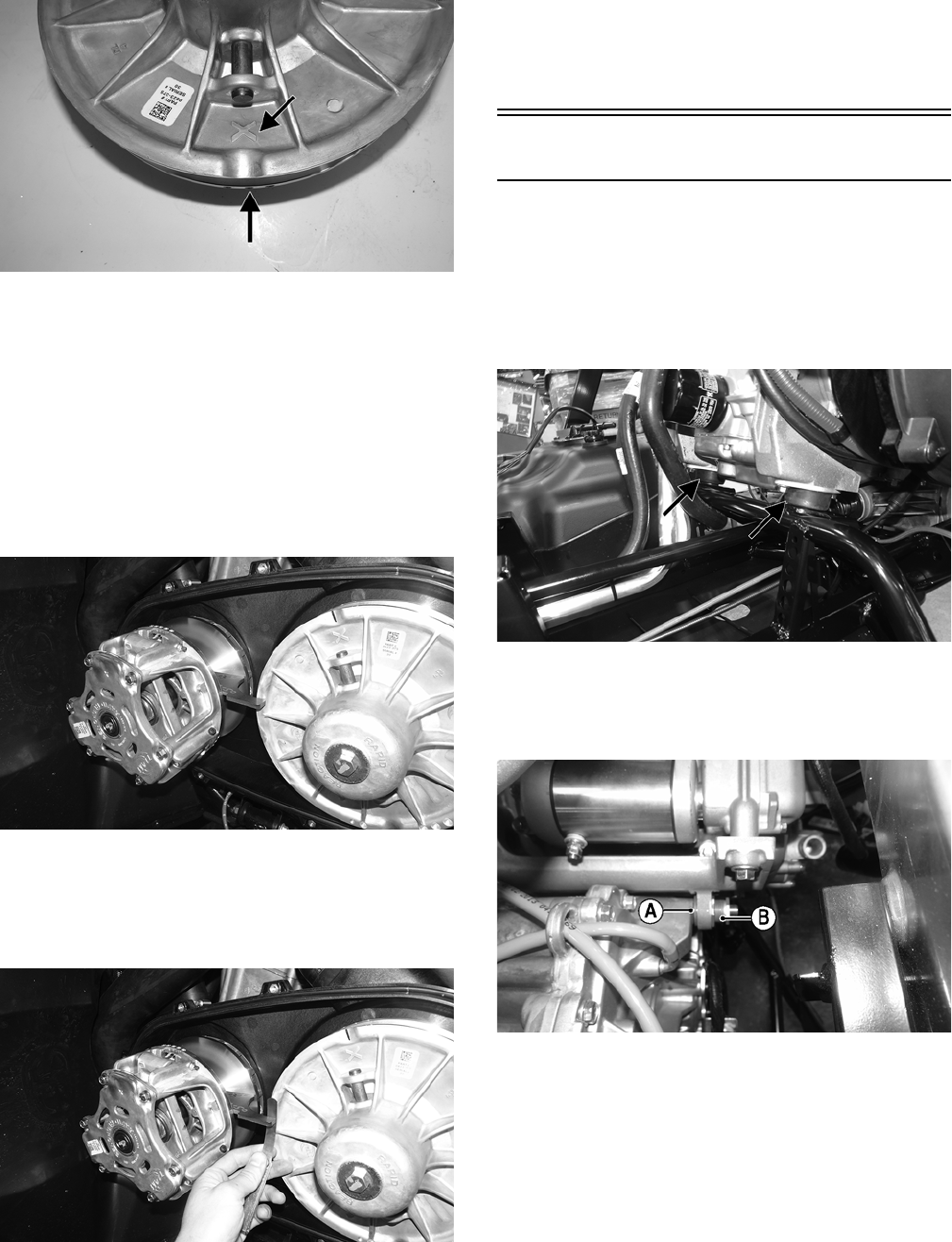
72
WT194A
CLUTCH ALIGNMENT
NOTE: If a clutch or any clutch component has been
replaced or if the technician is unsure of shim quan-
tity/placement, use the following procedure to check
and adjust clutch alignment.
1. With the drive clutch and driven clutch installed, posi-
tion the Clutch Alignment Bar inside the sheaves of
the drive clutch and on the outside of the driven
clutch. Make sure not to damage or scratch the
sheaves.
ROV374
2. The bar should just clear the outside edge of the sta-
tionary sheave of the driven clutch with a maximum
of 0.76 mm (0.030 in.) clearance. If the bar will not
clear the outside edge or clearance is more than the
specified amount, the alignment must be corrected.
ROV375
NOTE: If alignment must be corrected, add or
remove the appropriate alignment shim (p/n 1423-189
– 1.02 mm) or (p/n 1423-219 – 0.51 mm).
3. Repeat steps 1 and 2 as required until correct align-
ment is achieved.
NOTE: To install left-side components, see Engine –
Installing Engine.
Installing Engine
NOTE: The driveshaft must be secured to the trans-
axle before the engine is installed.
1. Using a proper lifting device, install the front engine
mount studs into the engine mounting brackets. In the
chassis, install the new lock nuts but do not tighten at
this time.
WT515A
2. Align and install the cap screws securing the engine to
the transaxle. Account for a spacing washer (A).
Apply anti-seize compound to the threads of the
adjuster nut (B) but do not tighten at this time.
WT474A
3. Using the appropriate center distance tool, install the
tool over the output shaft of the transaxle and using
the cap screw provided and secure it to the crankshaft.
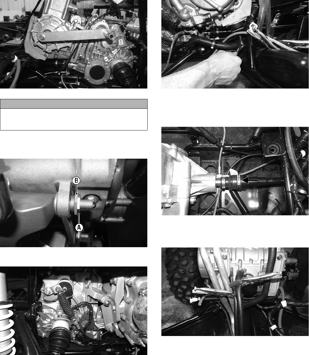
73
WT475
4. With the jam nut loosened towards the shoulder of the
adjuster nut, tighten the adjuster nut (A) to 10 ft-lb and
then the jam nut (B) to 15 ft-lb.
WT477A
5. Install the new lock nuts and tighten them to 75 ft-lb.
WT225A
6. Tighten the front engine mounting lock nuts to 25 ft-lb.
WT407
7. Align the rear driveshaft with the output shaft of the trans-
axle so they are joined together. Push the front axles rear-
ward until the front differential mounting holes are
properly aligned. Tighten the clamp securely.
WT424A
8. Remove the clamps from the oil hoses and install
them onto the engine oil fittings. Secure with the
worm clamps.
WT394
9. Install the coolant hose (as noted when removing)
connecting the cylinder and the water pump.
CAUTION
Care should be taken to install the tool over the output
shaft and slide the tool evenly towards the crankshaft to
avoid damaging the shaft.
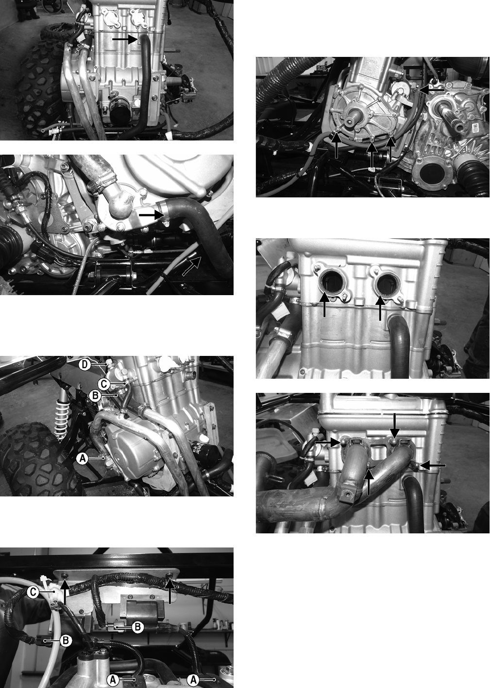
74
WT410A
WT399B
10. Connect the coolant return hose (A), the coolant out-
put hose (B), and the thermostat bypass hose (C).
Secure them with the hose clamps and connect the
ECT sensor (D).
WT411A
11. Install the coil bracket to the frame and tighten securely.
Install the spark plug caps (A); then connect the coil
connectors (B) and the cam position sensor (C).
WT396A
12. Remove the three cap screws from the PTO side of the
engine and install the clips securing the starter cable
and the gasline hose. Tighten the cap screws to 9 ft-lb.
Install the starter cable on the starter and tighten
securely.
WT414A
13. With the two gaskets in place, install the exhaust pipe.
Tighten to 8 ft-lb.
WT406A
WT398A
14. Carefully thread the oxygen (O2) sensor plug in
through the heat shield. Install the heat shield onto the
exhaust pipe and tighten to 10 ft-lb. Connect the oxy-
gen (O2) sensor.
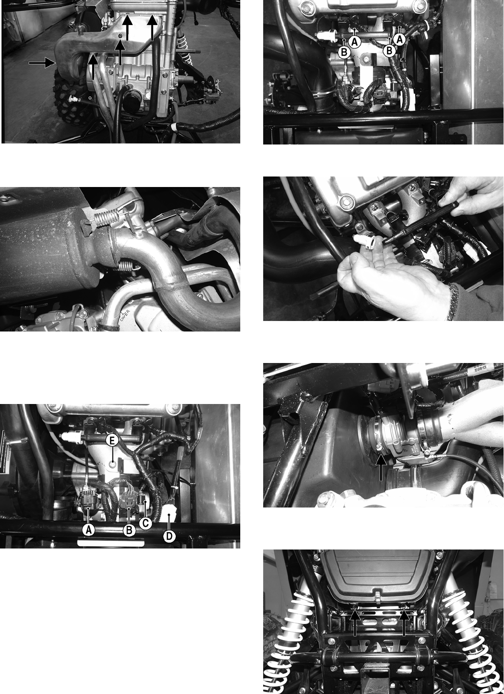
75
WT403A
15. Install the muffler and account for the gasket. Secure
using the two exhaust springs.
WT295
16. Install the throttle body into the intake manifold and
tighten the clamp securely. Connect the ISC connector
(A), MAP/IAT connector (B), TPS connector (C), and
stator wires (D). Secure the air box bracket (E) with
the cap screw and tighten to 5 ft-lb.
WT478A
17. Remove the towels from the intake manifold and
install the fuel rail. Account for two O-rings. Tighten
the existing cap screws (B) to 8 ft-lb and plug in the
injectors (A).
WT404A
18. Secure the gasline hose to the fuel rail.
WT402
19. Connect the air filter housing to the throttle body and
secure it with the worm clamp.
WT316A
20. Secure the bottom of the air filter housing with the
existing cap screws and tighten to 5 ft-lb.
WT315A
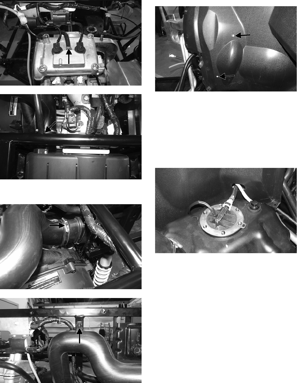
76
21. Install the engine breather tube and secure it with the
clamp.
WT405A
WT313B
22. Install the air intake tube and secure it to the frame
and air filter housing with the worm clamp.
WT311A
WT408A
23. Install the rear splash panels and secure them with the
cap screws. Install the push pins securing the wiring
harness to the left-side splash panel.
WT364A
24. Install the rear body panels and the side panels (see
Steering/Frame/Controls).
25. Install the seat belt assembly to the frame and tighten
to 60 ft-lb.
26. Install the vent hose, gasline hose, and fuel pump con-
nector.
NOTE: Be sure to route the gasline hose and vent
hose through the hole on the right side splash panel.
WT480
27. Install the cargo box and taillight assembly.
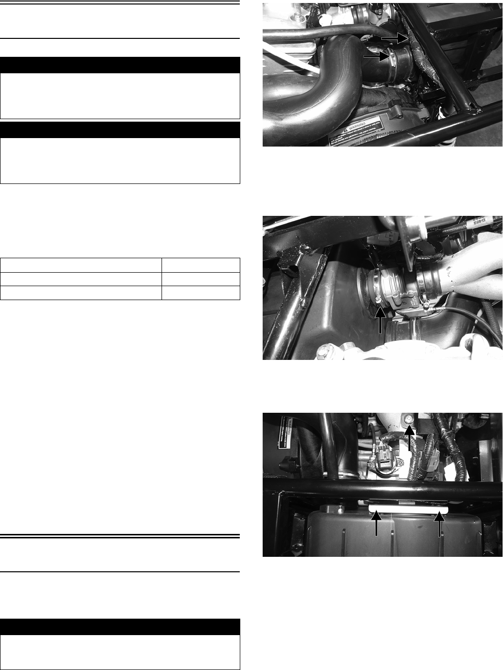
77
Fuel/Lubrication/Cooling
SPECIAL TOOLS
A number of special tools must be available to the techni-
cian when performing service procedures in this section.
Refer to the current Special Tools Catalog for the appropri-
ate tool description.
NOTE: Special tools are available from the Arctic
Cat Service Department.
TROUBLESHOOTING
1. Verify that the electric fuel pump is operating by lis-
tening for a “whirring” sound for approximately three
seconds after the ignition switch is turned to the ON
position. If no sound can be heard, see Fuel Pump/
Fuel Level Sensor in this section.
2. Check for a diagnostic trouble code (DTC) on the
LCD. If the light is flashing, see EFI Diagnostic Sys-
tem in Electrical System.
3. Make sure there is sufficient, clean gas in the gas tank.
4. Verify that the battery is sufficiently charged to crank
the engine over at normal speed.
5. Check the air filter housing and air filter for contami-
nation. Clean or replace as necessary (see Periodic
Maintenance/Tune-Up).
Throttle Body
1. Turn the ignition switch to the OFF position; then
remove the ignition key.
2. Remove the rear body panels and the cargo box.
3. Remove the clamp on the engine intake tube and
loosen the air intake clamp.
WT314A
NOTE: Removing the intake boot with the air filter
housing will aid in installation.
4. Loosen the throttle body clamp.
WT316A
5. Remove and discard the “patch lock” cap screws
securing the air intake housing bracket to the intake
manifold.
WT313C
6. Remove and retain the lower cap screws and grom-
mets.
! WARNING
Whenever the gasline hoses are removed (other than for
pressure testing), the battery must be disconnected to
prevent inadvertent activation of the electronic fuel
pump.
! WARNING
Whenever any maintenance or inspection is performed
on the fuel system during which there may be fuel leak-
age, there should be no welding, smoking, open flames,
etc., in the area.
Description p/n
Oil Pressure Test Kit 0644-495
Tachometer 0644-275
! WARNING
Do not turn the ignition switch to the ON position with
the hoses removed. Gasoline will be pumped by the
electric fuel pump causing a safety hazard.
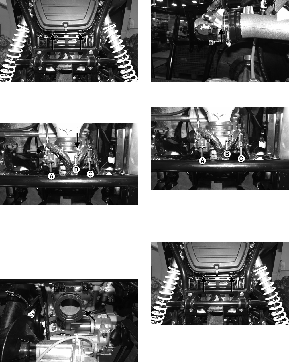
78
WT315A
7. Remove the air filter housing.
8. Remove the ISC connector (A), MAP/IAT connector
(B), and TPS connector (C); then disconnect the throt-
tle cable (D).
WT397B
9. Loosen the clamp securing the throttle body to the
intake manifold; then remove the throttle body.
10. Connect the throttle cable to the throttle arm; then
install the throttle cable housing cover to the throttle
body. Secure with the screw.
11. Make sure the alignment tab on the throttle body
aligns with the slot in the intake boot and install the
throttle body fully into the boot. Secure with worm
clams and tighten securely.
WT567A
WT566A
12. Connect the ISC connector (A), MAP/IAT connector
(B), and the TPS connector (C).
WT397A
13. Install the air filter housing in place and install the
outlet boot of the housing over the throttle body.
Secure with the clamp.
14. With the existing cap screws, grommets, and spacers,
secure the lower portion of air filter housing to the
frame. Tighten to 5 ft-lb.
WT315A
15. Using new “patch lock” cap screws, secure the air fil-
ter housing mount to the intake manifold (A). Tighten
to 5 ft-lb; then secure the mount to the air filter hous-
ing (B). Tighten to 36 in.lb.
16. Install the engine intake tube and air intake to the air
filter housing and secure with the clamps.
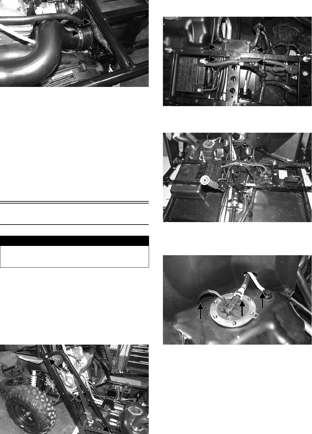
79
WT314A
17. Install the cargo box and rear body panels.
NOTE: If the throttle body, ECM, TPS, or ISC are
replaced, the EFI system must be synchronized. Use
the following procedure.
1. With the key off, depress accelerator pedal to Wide
Open Throttle (WOT).
2. Place the ignition key in the ON position and wait for
10 seconds.
3. Release the accelerator pedal, and wait an additional
10 seconds.
4. Turn the key to the OFF position and allow the gauge
to shut off.
Gas Tank
REMOVING
1. Remove the seats, engine access panel, and center console.
2. Remove the floor and side panels.
3. Remove the battery access panel and battery.
4. Remove the right rear side panel and right rear fender.
5. Remove the cap screws and discard the lock nuts
securing the right side frame tube.
WT365A
6. Remove the four cap screws securing the seat base to
the frame.
WT359A
7. Remove the remaining cap screws securing the frame
tubes to the frame. Remove both frame tubes.
WT360
8. Slide the gas tank slightly forward and disconnect the
gasline hose, vent hose, and fuel pump; then remove
the gas tank.
WT480A
INSTALLING
1. Place the gas tank into position; then connect the gasline
hose, vent hose, and fuel pump.
2. Place the two frame tubes into position and secure (but do
not tighten) with new “patch-lock” cap screws.
3. Install the remaining fasteners; then tighten all fasteners
securely.
4. Using new lock nuts, install the right side frame tube and
tighten securely.
! WARNING
Whenever any maintenance or inspection is made on the fuel
system during which there may be fuel leakage, there should
be no welding, smoking, open flames, etc., in the area.
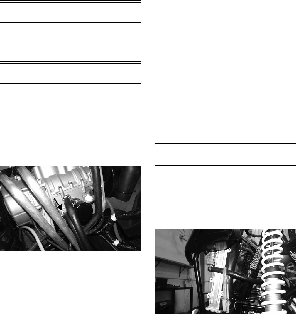
80
5. Place the battery into position and connect the battery
cables (negative cable first). Tighten the cables securely.
6. Install the floor and battery access panel.
7. Install the right rear side panel and the right rear fender.
8. Install the center console, engine access panel, and seats.
Gas/Vent Hoses
Replace the gas hose every two years. Damage from aging
may not always be visible. Do not bend or obstruct the
routing of the vent hoses. Make certain the vent hoses are
securely connected and the opposite ends are always open.
Oil Filter/Oil Pump
NOTE: Whenever internal engine components wear
excessively or break and whenever oil is contami-
nated, the oil pump should be replaced.
TESTING OIL PUMP PRESSURE
NOTE: The engine must be warmed up to operating
temperature (cooling fan cycling) for this test.
1. Remove the oil hose from the fitting nearest the oil filter
base.
WT568A
2. Using a suitable “T” fitting, connect Oil Pressure Test Kit
to the lower oil fitting and hose. Tighten all clamps
securely.
NOTE: Some oil seepage may occur when installing the
oil pressure gauge. Wipe up oil residue with a cloth.
3. Place the transmission in neutral and start the engine.
Set the speedometer/tachometer to RPM.
4. With the engine running at 3000 RPM and the coolant
at room temperature (approximately 70° F), the pres-
sure gauge must show 6.68-8.44 kg/cm2 (95-120 psi).
5. With the engine running at 3000 RPM and the coolant at
approximately 195° F (cooling fan cycling), the pressure
gauge must show 5.27-6.68 kg/cm2 (75-95 psi).
6. Remove the test kit from the vehicle and install the oil
hose. Tighten the clamps securely.
NOTE: If oil pressure is lower than specified, check
for an oil leak, clogged oil filter, or defective oil pump.
NOTE: If oil pressure is higher than specified, check
for too heavy engine oil weight (see General Informa-
tion), clogged oil passage, or improper installation or
type of the oil filter.
REMOVING/DISASSEMBLING
1. Remove the oil pump from the engine (see Center
Crankcase Components in Engine).
2. Remove oil pump components from crankcase.
CLEANING AND INSPECTING
1. Clean all oil-pump components.
2. Inspect the rotors for scoring and gouges.
3. Inspect the driveshaft and driven sprocket for damage.
4. Inspect the crankcase for scoring, cracks, or damage.
ASSEMBLING/INSTALLING
1. Place the rotors into the crankcase making sure the
dowel pin is in the groove of the rotor.
2. Place the cover onto the crankcase.
3. Secure the pump with the two cap screws coated with
blue Loctite #243. Tighten to 8 ft-lb.
Oil Cooler
REMOVING
1. Remove the hood and front bumper.
2. Using appropriate clamps, close-off both oil hoses.
3. Loosen the clamps securing the oil hoses to the oil
cooler; then place an absorbent towel under the con-
nection and remove the hoses.
WT455
4. Remove the cap screws securing the oil cooler to the
radiator and remove the oil cooler.
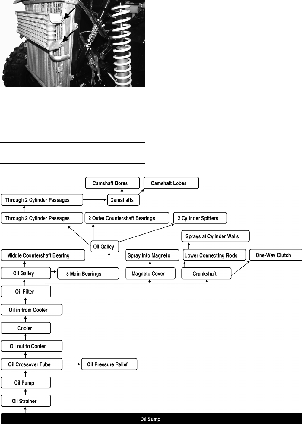
81
WT549A
CLEANING AND INSPECTING
1. Prior to washing, inspect the oil cooler for signs of
leaks, oily dirt build-up, or plugged cooling fins.
2. Wash the cooling fins using a garden hose and hot,
soapy water and a soft brush.
3. Inspect all mounting brackets and the oil inlet and out-
let for cracks or bends.
INSTALLING
1. Place the oil cooler into position and secure with the
existing hardware. Tighten securely.
2. Connect the oil hoses and secure with the hose
clamps. Tighten securely.
3. Remove the oil hose close-off clamps.
4. Start the engine and allow it to run for approximately
two minutes. Verify engine oil level and add oil as
required.
5. Install the hood and front bumper.
Oil Flow Chart
oil_flow_wt
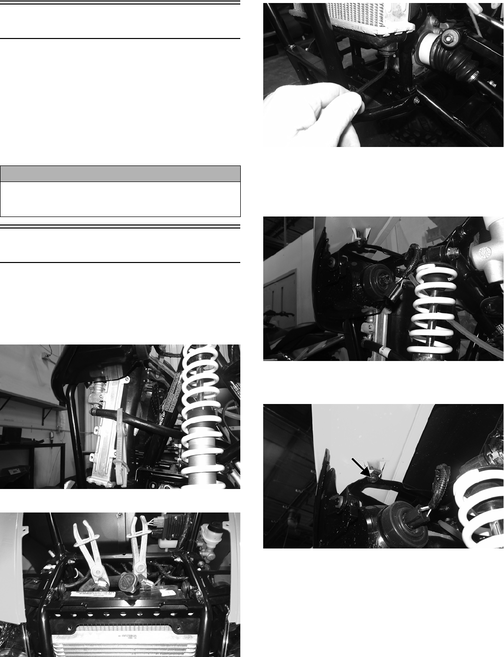
82
Liquid Cooling System
When filling the cooling system, use premixed Arctic Cat
Antifreeze. While the cooling system is being filled, air
pockets may develop; therefore, open the bleed screw on the
thermostat housing to allow air to bleed from the cooling
system. When clear coolant (no bubbles) is present, tighten
the bleed screw securely; then fill the cooling system to the
bottom of the stand pipe in the radiator neck. Run the engine
for five minutes after the initial fill, shut the engine off, and
then “top-off” the cooling system to the bottom of the stand
pipe in the radiator neck.
Radiator
REMOVING
1. Remove the hood and grille.
2. Using appropriate clamps, close-off the coolant hoses
to the radiator and the oil hoses to the oil cooler.
WT455
WT459
3. Using an appropriate Allen wrench, remove the drain
plug from the bottom of the radiator and drain the
coolant into a suitable pan. Account for an O-ring on
the drain plug.
WT452
NOTE: Opening the radiator cap will aid in draining
the radiator.
4. Disconnect the headlights.
WT463
5. Remove the cap screws securing each front fender to
the frame.
WT453A
6. Remove the cap screws securing the radiator to the
frame and disconnect the overflow bottle hose from
the top of the radiator.
CAUTION
After operating the vehicle for the initial 5-10 minutes,
stop the engine, allow the engine to cool down, and
check the coolant level. Add coolant as necessary.
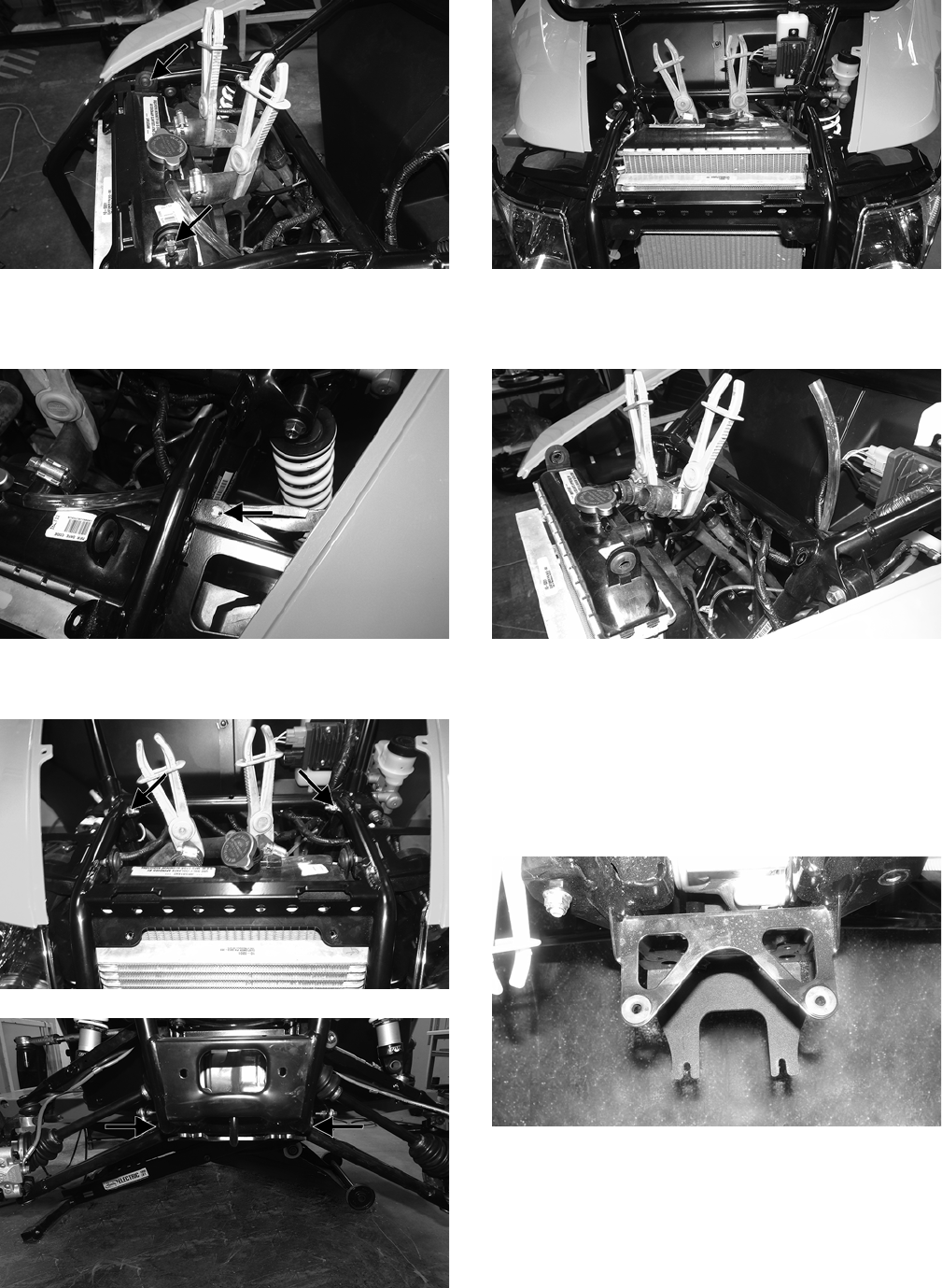
83
WT456A
7. Using a suitable prying tool, pry the clips out from
between the wiring harness and the frame; then push
the clips downward to remove them from the frame.
WT454A
8. Remove the cap screws securing the front bumper to
the frame. Discard the lock nuts.
WT459A
WT460A
9. Pull the bumper away from the vehicle.
WT461
10. Disconnect the radiator fan and remove the radiator/
oil cooler from the vehicle. Drain the remaining cool-
ant into a suitable container.
WT458
NOTE: If the radiator will be replaced, transfer the
cooling fan and oil cooler to the new radiator.
INSTALLING
1. Place the assembled radiator studs into the mounting
holes on the radiator bracket. Connect the coolant
hoses and oil hoses; then secure them with the worm
hose clamps. Remove the close-off clamps.
WT464
2. Connect the fan motor connector and connect the
overflow bottle hose to the radiator. Install the drain
plug with O-ring and tighten securely.
3. Install the bumper frame in place and using the exist-
ing cap screws and new lock nuts, finger-tighten only
at this time.
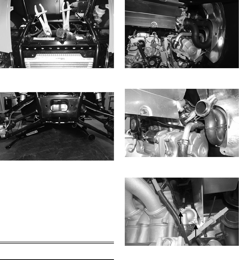
84
WT459A
4. Install the lower bumper cap screws and tighten the
upper and lower bumper cap screws to 20 ft-lb.
WT460A
5. Install the cap screws and nuts securing the radiator to
the frame. Tighten to 8 ft-lb.
6. Install the cap screws securing the front fenders to the
frame. Tighten securely and plug in the headlights.
7. Using the existing cap screws, secure the grille and
tighten securely.
8. Fill the radiator with the proper mixture of coolant
until there are no more air bubbles present and the
coolant level is above the cooling fins inside the radia-
tor. Tighten the radiator cap.
9. Install the hood and tighten the two quarter-turn fas-
teners.
Thermostat
REMOVING
NOTE: The thermostat is located on the right side in
a housing in-line with the coolant hose behind the
muffler.
NOTE: Removing the muffler will aid in removing.
1. Drain a couple of cups of coolant from the water
pump
2. Clamp off the coolant hoses and place an absorbent
towel under the thermostat.
WT535
3. Remove the hose from the bottom of the thermostat
housing and push out of the way.
WT547
4. Remove the two cap screws securing the thermostat
housing together. Remove the thermostat.
WT534A
INSPECTING
1. Inspect the thermostat for corrosion or spring damage.
2. Using the following procedure, inspect the thermostat
for proper operation.
A. Suspend the thermostat in a container filled with
water.
B. Heat the water and monitor the temperature with a
thermometer.
C. The thermostat should start to open at 80.0-84.0° C
(176-183° F).
D. If the thermostat does not open, it must be
replaced.
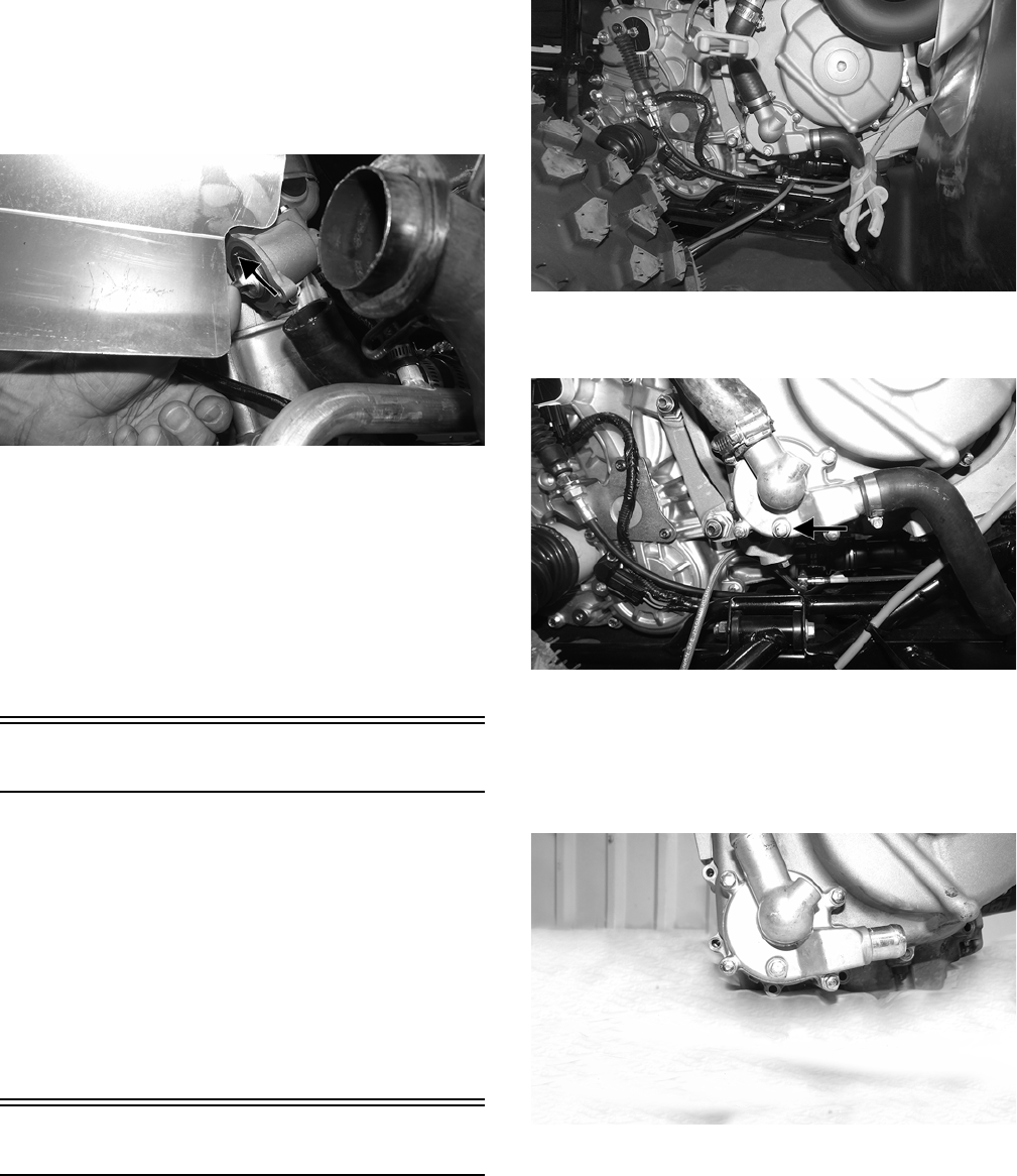
85
3. Inspect all coolant hoses, connections, and clamps for
deterioration, cracks, and wear.
NOTE: All coolant hoses and clamps should be
replaced every four years or 4000 miles.
INSTALLING
1. Install the thermostat into the thermostat housing so
the bleeder valve is facing up.
WT546A
2. Install the thermostat cover; then making sure the
thermostat is properly seated, tighten the cap screws to
5 ft-lb.
3. Install the hose on the bottom of thermostat housing
and secure with the hose clamp.
4. Remove the close-off clamps; then install the muffler
and secure with the springs.
5. Add the recommended anti-freeze as required; then
bleed the cooling system and check for leaks.
Fan
REMOVING
1. Remove the radiator.
2. Remove the fan assembly from the radiator.
INSTALLING
1. Position the fan assembly on the radiator; then secure
with existing hardware.
NOTE: The fan wiring must be directed downward.
2. Install the radiator.
Water Pump
NOTE: The water pump is a non-serviceable compo-
nent. It must be replaced as an assembly.
REMOVING
NOTE: If the engine is still in vehicle, drain the oil
and remover the muffler, exhaust pipe, and right-side
inner splash panel.
1. Using appropriate clamps, close-off the coolant hose
before and after the water pump.
WT533
2. Drain the coolant from the pump and remove the
hoses from the water pump.
WT399A
3. Remove the cap screws securing the magneto cover to
the engine.
4. Remove the cap screws securing the impeller cover to
the magneto cover. Account for an O-ring and two
dowel pins.
WT578
5. Remove the E-clip and washer from the impeller shaft
and remove impeller from case half.
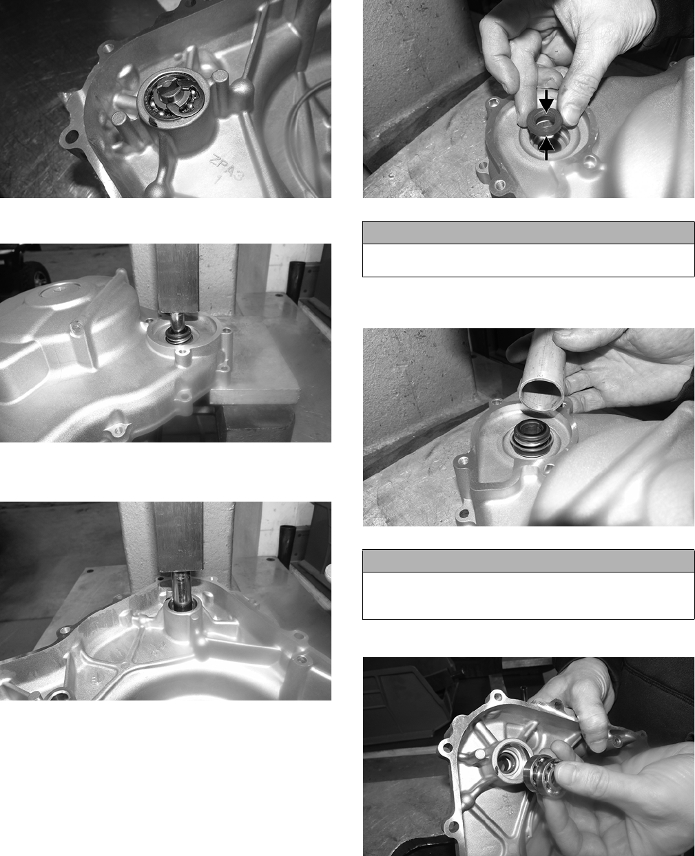
86
WT571
6. Using an appropriate press, remove the two bearings.
WT572
7. Using an appropriate press, remove the rubber seal
and mechanical seal as an assembly.
WT570
INSTALLING
1. Apply grease to the inside and outside of the seal; then
press in the rubber seal.
WT576A
2. Using a section of 1” pipe, press in the mechanical
seal.
WT575
3. Individually press in the bearings.
WT573
4. Install the impeller in place and secure with a washer
and E-clip.
5. Install the magneto cover and secure with the cap
screws. Tighten the screws to 11 ft-lb.
6. Install the impeller cover and secure with the cap
screws. Tighten the screws to 11 ft-lb.
CAUTION
Only apply pressure to the center race of the seal while
installing to avoid damaging the seal.
CAUTION
It is critical while pressing the seal into position to
press on the outer diameter of the seal to avoid damag-
ing the mechanical seal.
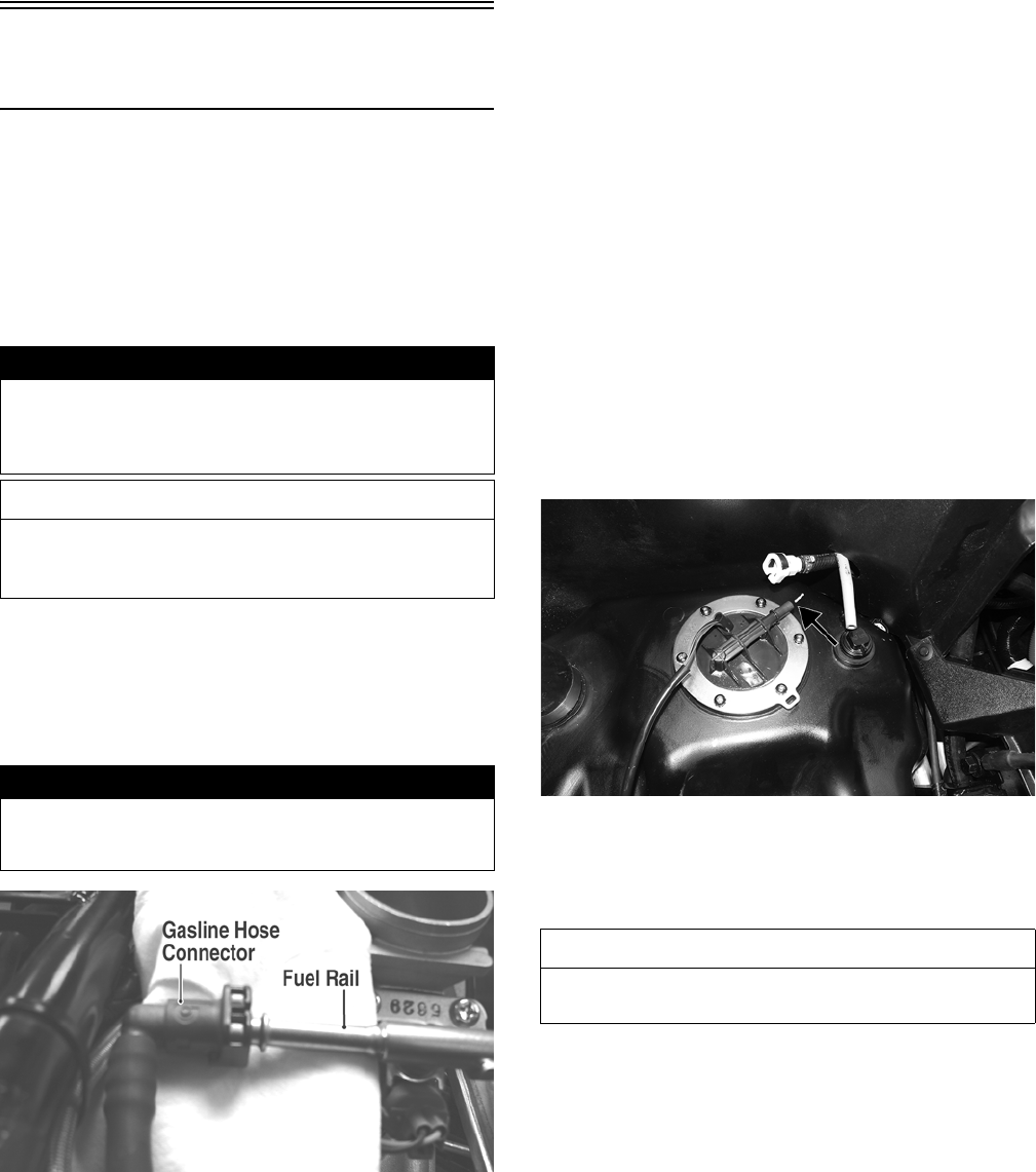
87
NOTE: The two longer cap screws go in the dowel
pin locations.
7. Install the coolant hoses; then add the appropriate
mixture of coolant until the appropriate level is
reached (see Fuel/Cooling/Lubricant).
8. If removed, install the muffler, exhaust pipe, and
right-side inner splash panel.
9. If drained, add the appropriate engine oil until the cor-
rect level has been reached.
Fuel Pump/Fuel Level
Sensor
NOTE: Preliminary checks may be performed on
this component using the diagnostic mode on the
LCD gauge (see EFI Diagnostic System in the Electri-
cal System section).
The fuel pump and fuel level sensor are not serviceable
components. If either component fails, it must be replaced.
TESTING
1. Turn the ignition switch ON and listen for a momen-
tary “whirring” sound of the pump building pressure.
If the sound is heard (10 seconds), no electrical checks
are necessary. Turn the ignition switch OFF.
2. Disconnect the gasline hose from the fuel rail; then
install a suitable pressure gauge.
FI092A
3. Turn the ignition switch to the ON position. The fuel
pressure should build until the pump shuts off. Pres-
sure should read 3.0 kg-cm2 (43 psi).
4. Check for any flashing DTC (Diagnostic Trouble
Code) on the digital gauge. A disconnected or faulty
tilt sensor will cause the fuel pump not to run and a
code to flash.
5. If the pump is not running, check the 10 amp FUEL
fuse in the PDM under the passenger seat. Replace as
necessary and check for fuel pump operation.
6. If fuse is OK, check the FUEL relay by swapping with
another relay. If the pump runs, replace the FUEL
relay.
7. If the pump still is inoperative, proceed to REMOV-
ING.
REMOVING
1. Remove the passenger seat.
NOTE: The power supply/wiring to the fuel pump
could be checked by using a multimeter set to DC
volts; then check for battery voltage by turning the
ignition to ON and checking between the black and
red wires.
2. Disconnect the fuel pump/fuel level sender connector;
then wrap a shop towel around the gasline connector
and disconnect the gasline from the fuel pump.
3. Mark the components for assembling purposes and
remove the screws securing the fuel pump to the gas
tank.
WT552A
4. Carefully remove the fuel pump/fuel level sender
assembly from the gas tank; then tape over the open-
ing.
INSPECTING
1. Move the float lever and check for free movement.
The float assembly should return to the lower position
without force. If not, replace the fuel level sensor
assembly.
2. Test the fuel level sensor by connecting a multimeter
to the fuel level sensor leads (A); then select OHMS.
The multimeter should show 0-5 ohms at full fuel
position and 95-105 ohms at empty.
! WARNING
Whenever any maintenance or inspection is made on
the fuel system during which there may be fuel leakage,
there should be no welding, smoking, open flames, etc.,
in the area.
AT THIS POINT
Prior to removing the fuel pump, the following test
should be performed to determine that removal is
necessary.
! WARNING
Gasoline may be under pressure. Place an absorbent
towel under the connector to absorb any gasoline spray
when disconnecting.
AT THIS POINT
If the pump has failed earlier test and must be
replaced, proceed to INSTALLING.
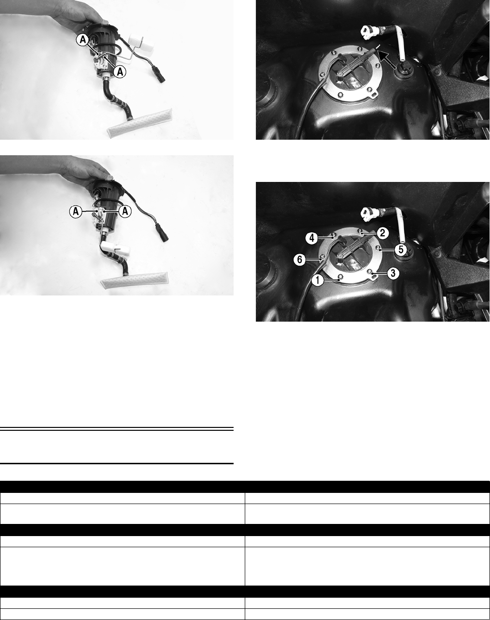
88
WT550B
WT551B
NOTE: If readings are erratic, clean the resistor
wiper and resistor with clean alcohol and retest. If
still not correct, replace the fuel level sensor.
INSTALLING
1. Carefully place the fuel pump assembly into the gas
tank referencing orientation marks made during
removal.
WT552A
2. Secure the pump assembly with the mounting screws
and tighten securely in a crisscross pattern.
WT552B
3. Connect the electrical connector and the gasline hose
connector to the fuel pump.
4. Install the passenger seat.
Troubleshooting
FULL
EMPTY
Problem: Starting impaired
Condition Remedy
1. Gas contaminated
2. Throttle cable too tight
1. Drain gas tank and fill with clean gas
2. Adjust throttle cable and synchronize EFI system (see Section 5)
Problem: Idling or low speed impaired
Condition Remedy
1. TPS out of adjustment
2. Throttle cable too tight
3. Throttle body dirty
1. Adjust TPS (out of warranty) or replace the throttle body
(under warranty)
2. Adjust throttle cable and synchronize EFI system (see Section 5)
3. Clean throttle body
Problem: Medium or high speed impaired
Condition Remedy
1. High RPM “cut out” against RPM limiter 1. Decrease RPM speed
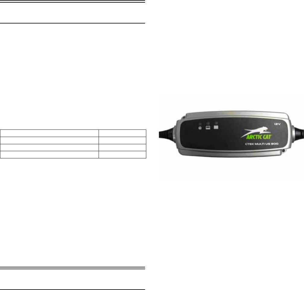
89
Electrical System
NOTE: Certain components and sensors can be
checked by using the EFI diagnostic system and digi-
tal gauge (see EFI Diagnostic System in this section
for more information).
The electrical connections should be checked periodically for
proper function. In case of an electrical failure, check fuses,
connections (for tightness, corrosion, damage), and/or bulbs.
SPECIAL TOOLS
A number of special tools must be available to the techni-
cian when performing service procedures in this section.
Refer to the current Special Tools Catalog for the appropri-
ate tool description.
NOTE: Special tools are available from the Arctic
Cat Service Department.
TESTING ELECTRICAL
COMPONENTS
All of the electrical tests should be made using the Fluke
Model 77 Multimeter. If any other type of meter is used,
readings may vary due to internal circuitry. When trouble-
shooting a specific component, always verify first the
fuse(s) are good, the LED(s) are good, the connections are
clean and tight, the battery is fully charged, and all appro-
priate switches are activated.
NOTE: For absolute accuracy, all tests should be
made at room temperature of 68° F.
Battery
NOTE: Preliminary checks may be performed on this
component using the diagnostic mode on the LCD
gauge (see EFI Diagnostic System in this section)
The battery is located under the passenger seat.
NOTE: To access the battery box, the battery cover
must be removed.
After being in service, batteries require regular cleaning
and recharging in order to deliver peak performance and
maximum service life. The following procedures are rec-
ommended for cleaning and maintaining sealed batteries.
Always read and follow instructions provided with battery
chargers and battery products.
NOTE: Refer to all warnings and cautions provided
with the battery or battery maintainer/charger.
Loss of battery charge may be caused by ambient temper-
ature, ignition OFF current draw, corroded terminals, self
discharge, frequent start/stops, and short engine run
times. Frequent winch usage, snowplowing, extended
low RPM operation, short trips, and high amperage
accessory usage are also reasons for battery discharge.
Maintenance Charging
NOTE: Arctic Cat recommends the use of the CTEK
Multi US 800 or the CTEK Multi US 3300 for battery
maintenance charging. Maintenance charging is
required on all batteries not used for more than two
weeks or as required by battery drain.
800E
1. When charging a battery in the vehicle, be sure the
ignition switch is in the OFF position.
2. Clean the battery terminals with a solution of baking
soda and water.
NOTE: The sealing strip should NOT be removed
and NO fluid should be added.
3. Be sure the charger and battery are in a well-venti-
lated area. Be sure the charger is unplugged from the
110-volt electrical outlet.
4. Connect the red terminal lead from the charger to the
positive terminal of the battery; then connect the
black terminal lead of the charger to the negative ter-
minal of the battery.
NOTE: Optional battery charging adapters are avail-
able from your authorized Arctic Cat dealer to connect
directly to your vehicle from the recommended char-
gers to simplify the maintenance charging process.
Check with your authorized Arctic Cat dealer for proper
installation of these charging adapter connectors.
5. Plug the battery charger into a 110-volt electrical
outlet.
6. If using the CTEK Multi US 800, there are no further
buttons to push. If using the CTEK Multi US 3300,
press the Mode button (A) at the left of the charger
until the Maintenance Charge Icon (B) at the bottom
illuminates. The Normal Charge Indicator (C) should
illuminate on the upper portion of the battery charger.
Description p/n
Fluke Model 77 Multimeter 0644-559
Timing Light 0644-296
MaxiClips 0744-041
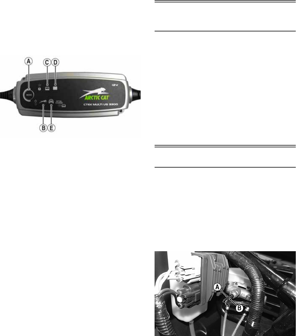
90
NOTE: The maintainer/charger will charge the bat-
tery to 95% capacity at which time the Maintenance
Charge Indicator (D) will illuminate and the main-
tainer/charger will change to pulse/float mainte-
nance. If the battery falls below 12.9 DC volts, the
charger will automatically start again at the first step
of the charge sequence.
3300A
NOTE: Not using a battery charger with the proper
float maintenance will damage the battery if con-
nected over extended periods.
Charging
NOTE: Arctic Cat recommends the use of the CTEK
Multi US 800 or the CTEK Multi US 3300 for battery
maintenance charging.
1. Be sure the battery and terminals have been cleaned
with a baking soda and water solution.
NOTE: The sealing strip should NOT be removed
and NO fluid should be added.
2. Be sure the charger and battery are in a well-venti-
lated area. Be sure the charger is unplugged from the
110-volt electrical outlet.
3. Connect the red terminal lead from the charger to the
positive terminal of the battery; then connect the
black terminal lead of the charger to the negative ter-
minal of the battery.
4. Plug the charger into a 110-volt electrical outlet.
5. By pushing the Mode button (A) on the left side of
the charger, select the Normal Charge Icon (E). The
Normal Charge Indicator (C) should illuminate on
the upper left portion of the charger.
6. The battery will charge to 95% of its capacity at
which time the Maintenance Charge Indicator (D)
will illuminate.
NOTE: For optimal charge and performance, leave
the charger connected to the battery for a minimum 1
hour after the Maintenance Charge Indicator (D) illu-
minates. If the battery becomes hot to the touch, stop
charging. Resume after it has cooled.
7. Once the battery has reached full charge, unplug the
charger from the 110-volt electrical outlet.
Accessory Receptacle/
Connector
NOTE: This test procedure is for either the recepta-
cles or the connectors.
VOLTAGE
1. Turn the ignition switch to the ON position; then set
the meter selector to the DC Voltage position.
2. Connect the red tester lead to the positive connector;
then connect the black tester lead to the negative con-
nector.
3. The meter must show battery voltage.
NOTE: If the meter shows no battery voltage, trou-
bleshoot the fuse, receptacle, connector, or the main
wiring harness.
Brakelight Switch
The switch connectors are spade-type connectors on the
side of the master cylinder.
NOTE: The ignition switch must be in the ON position.
VOLTAGE (Wiring Harness
Connector)
1. Set the meter selector to the DC Voltage position.
2. Connect the red tester lead to the orange wire (B); then
connect the black tester lead to the red/blue wire (A).
WT556A
3. The meter must show battery voltage.
NOTE: If the meter shows no battery voltage, trou-
bleshoot the fuse, switch, or the main wiring harness.
NOTE: If the meter shows battery voltage, the main
wiring harness is good; proceed to test the switch/
component and the connector.
RESISTANCE (Switch Connector)
NOTE: The brake pedal must be depressed for this
test.
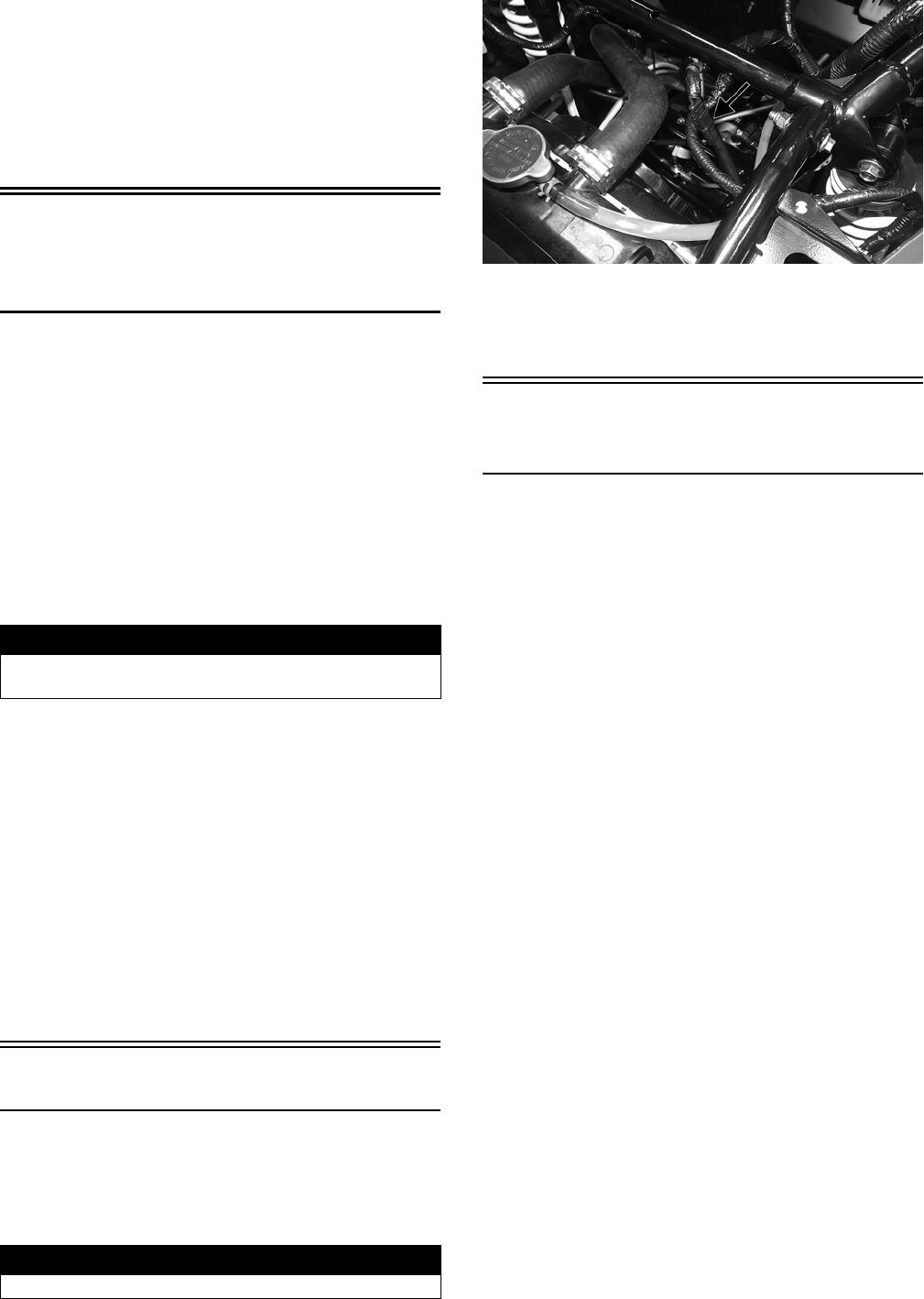
91
1. Set the meter selector to the OHMS position.
2. Connect the red tester lead to one terminal; then con-
nect the black tester lead to the other terminal.
3. When the pedal is depressed, the meter must show less
than 1 ohm.
NOTE: If the meter shows more than 1 ohm of resis-
tance, replace the switch.
Engine Coolant
Temperature (ECT)
Sensor
NOTE: Preliminary checks may be performed on this
component using the diagnostic mode on the LCD
gauge (see EFI Diagnostic System in this section).
1. Connect the meter leads (selector in OHMS position)
to the sensor terminals.
2. Suspend the sensor and a thermometer in a container
of cooking oil; then heat the oil.
NOTE: Neither the sensor nor the thermometer
should be allowed to touch the bottom of the con-
tainer or inaccurate readings will occur. Use wire
holders to suspend the sensor and thermometer.
3. On the ECT sensor when the temperature reaches 60°
C (140° F), the meter should read approximately 703
ohms ± 5%.
4. On the ECT sensor when the temperature reaches 90°
C (194° F), the meter should read approximately 260
ohms ± 5%.
5. On the ECT sensor when temperature reaches 120° C
(248° F), the meter should read approximately 111
ohms ± 5%.
6. If the readings are not as indicated, the sensor must be
replaced.
7. Install the sensor and tighten securely.
8. Connect the leads.
Fan Motor
NOTE: To determine if the fan motor is good, con-
nect the red wire from the fan connector to a 12 volt
battery; then connect the black wire from the fan con-
nector to ground. The fan should operate.
WT558A
NOTE: Fan motor resistance checks are not recom-
mended. Resistance values change with the motor
commutator position.
Power Distribution
Module (PDM)
FUSES/RELAYS
NOTE: To access fuses and relays, compress the
locking tabs on either side of the PDM cover and lift off.
The fuses are located in a power distribution module under
the driver’s seat. If there is any type of electrical system
failure, always check the fuses first.
The 4-pin relays are identical plug-in type located on the power
distribution module. Relay function can be checked by switch-
ing relay positions. The 4-pin relays are interchangeable.
NOTE: The PDM base and wiring harness are not a ser-
viceable component and must be replaced as an assem-
bly.
1. Remove a fuse from the power distribution module.
2. Set the meter selector to the DC Voltage position.
3. Connect the black tester lead to ground.
4. Using the red tester lead, contact each end of the fuse
holder connector terminals individually.
5. The meter must show battery voltage on one fuse ter-
minal but not the other.
NOTE: Battery voltage will be indicated from only
one side of the fuse holder connector terminal; the
other side will show no voltage.
NOTE: When testing the HI-BEAM fuse holder, the
headlight switch must be in the HI position; when
testing the LO-BEAM fuse holder, the headlight dim-
mer switch must be in the LO position.
NOTE: If the meter shows no battery voltage, trou-
bleshoot the battery, switches, power distribution
module, or the main wiring harness.
! WARNING
Wear insulated gloves and safety glasses. Heated oil
can cause severe burns.
! WARNING
Care should be taken to keep clear of the fan blades.
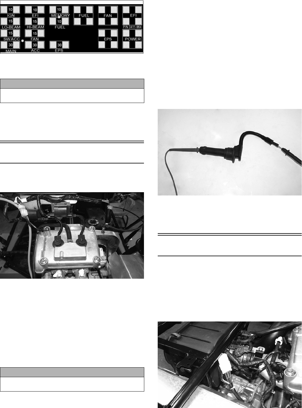
92
3411-964
This vehicle uses automotive-style (see-through) fuses. The
fuses can be visually inspected; replace fuse if link is open.
NOTE: Make sure the fuses are returned to their
proper position according to amperage. Refer to the
amperage listed under each fuse on the power distri-
bution module.
Ignition Coils
The ignition coils are mounted to the upper frame above
the engine.
WT405
VOLTAGE (Primary Coil)
1. Set the meter selector to the DC Voltage position; then
disconnect the connector from the coil to be tested.
2. Using MaxiClips, connect the red tester lead to the
orange wire and the black tester lead to ground.
3. Turn the ignition switch to the ON position. The meter
must show battery voltage.
4. Repeat for the other coil.
RESISTANCE (Primary Winding)
NOTE: For this test, the meter selector should be
set to the OHMS position.
1. Disconnect the coil connector. Connect the red tester
lead to one coil terminal; then connect the black tester
lead to the other coil terminal.
2. Resistance must be less than 1 ohm.
NOTE: If the meter does not show as specified,
replace ignition coil.
NOTE: Secondary coil resistance checks are not
recommended. An internal diode in the coil prevents
accurate secondary resistance measurements.
Spark Plug Cap
1. Connect the red tester lead to one end of the cap; then
connect the black tester lead to the other end of the
cap.
WT553
2. The meter must show 5000 ohms.
NOTE: If the meter does not show as specified,
replace the spark plug cap.
EFI Sensors/Components
CRANKSHAFT POSITION (CKP)
SENSOR
NOTE: The cargo box must be removed for this pro-
cedure.
The three-pin CKP connector is located in front of the air
filter.
WT562
1. Set the meter selector to the OHMS position.
CAUTION
Always replace a blown fuse with a fuse of the same
type and rating.
CAUTION
Always disconnect the battery when performing resis-
tance tests to avoid damaging the multimeter.
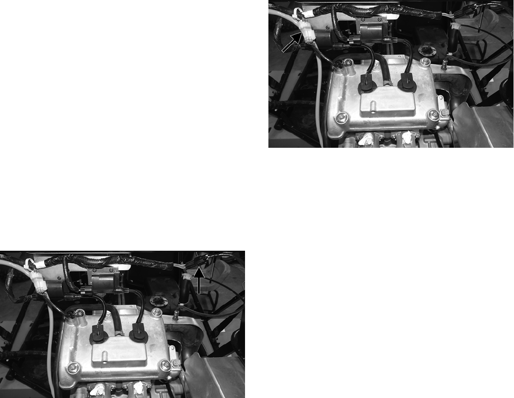
93
2. Connect the red tester lead to the brown wire; then
connect the black tester lead to the white wire. The
meter reading must be 100-150 ohms.
3. Set the meter selector to the AC Voltage position.
NOTE: The battery must be at full charge for these
tests.
4. Using MaxiClips, connect the red tester lead to the
brown/green wire; then connect the black tester lead
to the green/white wire.
5. Crank the engine over using the electric starter.
6. The meter should read approximately 1.0 volt.
OXYGEN (O2) SENSOR
The oxygen (O2) sensor is located in the exhaust pipe.
NOTE: When testing the resistance of the sensor’s
heater, the engine/exhaust pipe must be at room tem-
perature (65-75° F) or inaccurate readings will occur.
1. Remove the cargo box.
2. Disconnect the sensor.
WT405C
NOTE: For this test, the meter must be in OHMS
position.
3. On the sensor side of connector, connect the black (nega-
tive) test lead to one white wire pin; then connect the red
(positive) test lead to the other white wire pin. The read-
ing should be between 6.7 and 10.1 ohms.
NOTE: If the meter does not read as specified,
replace the sensor.
4. Select DC Voltage on the tester and turn the ignition
switch to the ON position.
5. Connect the black tester lead to the black/green wire
and the red tester lead to the orange wire. The meter
should read battery voltage. If the meter does not read
as specified, check the wiring.
NOTE: When testing the resistance of the sensor’s
heater, the engine/exhaust pipe must be at room tem-
perature (65-75° F) or inaccurate readings will occur.
CAM POSITION SENSOR
The cam position sensor is located on the cylinder head.
1. Remove the cargo box.
2. Disconnect the sensor.
WT405D
NOTE: For this test, the meter must be in OHMS
position.
3. On the sensor side of connector, connect the black (nega-
tive) test lead to one black wire pin; then connect the red
(positive) test lead to the other black wire pin. The read-
ing should be between 6.7k and 10.1k ohms.
NOTE: If the meter does not read as specified,
replace the sensor.
4. Select DC Voltage on the tester and turn the ignition
switch to the ON position.
5. Connect the black tester lead to the pink/black wire
and the red tester lead to the orange wire. The meter
should read battery voltage. If the meter does not read
as specified, check the wiring.
MANIFOLD ABSOLUTE PRESSURE/
INLET AIR TEMPERATURE (MAP/IAT)
SENSOR
NOTE: Preliminary checks may be performed on this
component using the diagnostic mode on the LCD
gauge (see EFI Diagnostic System in this section).
1. Disconnect the MAP/IAT connector from the sensor
located on top of the throttle body.
2. Select DC Voltage on the tester and turn the ignition
switch to the ON position.
3. Connect the black tester lead to the pink/black wire and
the red tester lead to the green/black wire. The meter
should read 4.5-5.5 DC volts. If the meter does not read
as specified, check the ECM connector or wiring.
4. Connect the MAP/IAT to the harness; then using Maxi-
Clips, connect the red tester lead to the brown/white
wire and the black tester lead to the pink/black wire.
With the engine running at idle speed, the meter should
read approximately 2.5 DC volts (MAP sensor signal).
5. Connect the red tester lead to the green/red wire. With
the engine at idle and at room temperature (approxi-
mately 68° F), the meter should read approximately
2.9 DC volts (IAT sensor signal).
NOTE: If the meter does not read as specified,
replace the sensor.
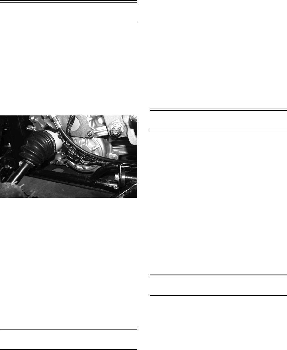
94
Speed Sensor
NOTE: Preliminary checks may be performed on this
component using the diagnostic mode on the LCD
gauge (see EFI Diagnostic System in this section).
NOTE: Prior to testing the speed sensor, inspect the
three-wire connector on the speed sensor for con-
tamination, broken pins, and/or corrosion.
1. Set the meter selector to the DC Voltage position.
2. Using MaxiClips, connect the red tester lead to the
orange wire; then connect the black tester lead to the
black wire.
WT554
3. Turn the ignition switch to the ON position.
4. The meter must show approximately 6 DC volts.
5. Leave the black tester lead connected; then connect
the red tester lead to the pink/white wire.
6. Slowly move the vehicle forward or backward; the meter
must show 0 and approximately 6 DC volts alternately.
NOTE: If the sensor tests are not within specifica-
tions, the sensor must be replaced.
To replace a speed sensor, use the following procedure.
1. Disconnect the three-wire connector from the speed sensor;
then remove the cap screw securing the sensor to the trans-
axle.
2. Install the new speed sensor into the transaxle with new
O-ring lightly coated with multi-purpose grease; then
secure the sensor with the cap screw. Tighten to 10 ft-lb.
Ignition Switch
To access the ignition switch, the dash must be loosened
and slid to the rear.
VOLTAGE
1. Set the meter selector to the DC Voltage position.
2. Connect the red meter lead to the red wire; then con-
nect the black meter lead to ground.
3. Meter must show battery voltage.
NOTE: If the meter shows no battery voltage, trou-
bleshoot the main 30 amp fuse, the battery, or the
main wiring harness.
4. Connect the red meter lead to the brown/black wire;
then with the black lead grounded, turn the ignition
switch to the ON position. The meter must show bat-
tery voltage.
5. Connect the red meter lead to the yellow/green wire;
then with the black lead grounded, turn the ignition
switch to the START position. The starter should
engage and the meter must show battery voltage.
NOTE: When the starter is engaged, battery voltage
will drop to approximately 10.5 DC volts.
Headlight Switch
VOLTAGE
1. Connect the red meter lead to the red/black wire; then con-
nect the black meter lead to the black wire.
2. Turn the ignition switch to the ON position. The meter
must show battery voltage.
NOTE: If the meter does not show battery voltage,
troubleshoot the LIGHTS fuse on the power distribu-
tion module, the ignition switch, or the main harness.
3. Using MaxiClips, connect the red meter lead to either of
the two yellow wires; then select the high beam position
on the headlight switch. The meter must show battery
voltage.
4. Using MaxiClips, connect the red meter lead to either of
the two gray wires; then select the low beam position on
the headlight switch. The meter must show battery voltage.
NOTE: The battery voltage will show lower in steps
3 and 4 due to electrical loading of the headlights.
Drive Select Switch
RESISTANCE
1. Remove the switch assembly from the dash; then discon-
nect the harness from the switch.
NOTE: The switch can be removed from the dash
using a thin, flat pry bar or suitable putty knife. It is not
necessary to remove the dash to remove the switch.
2. Using an ohmmeter, the following readings must be
observed.
NOTE: Switch terminals A and D are connected with
a small metallic jumper.
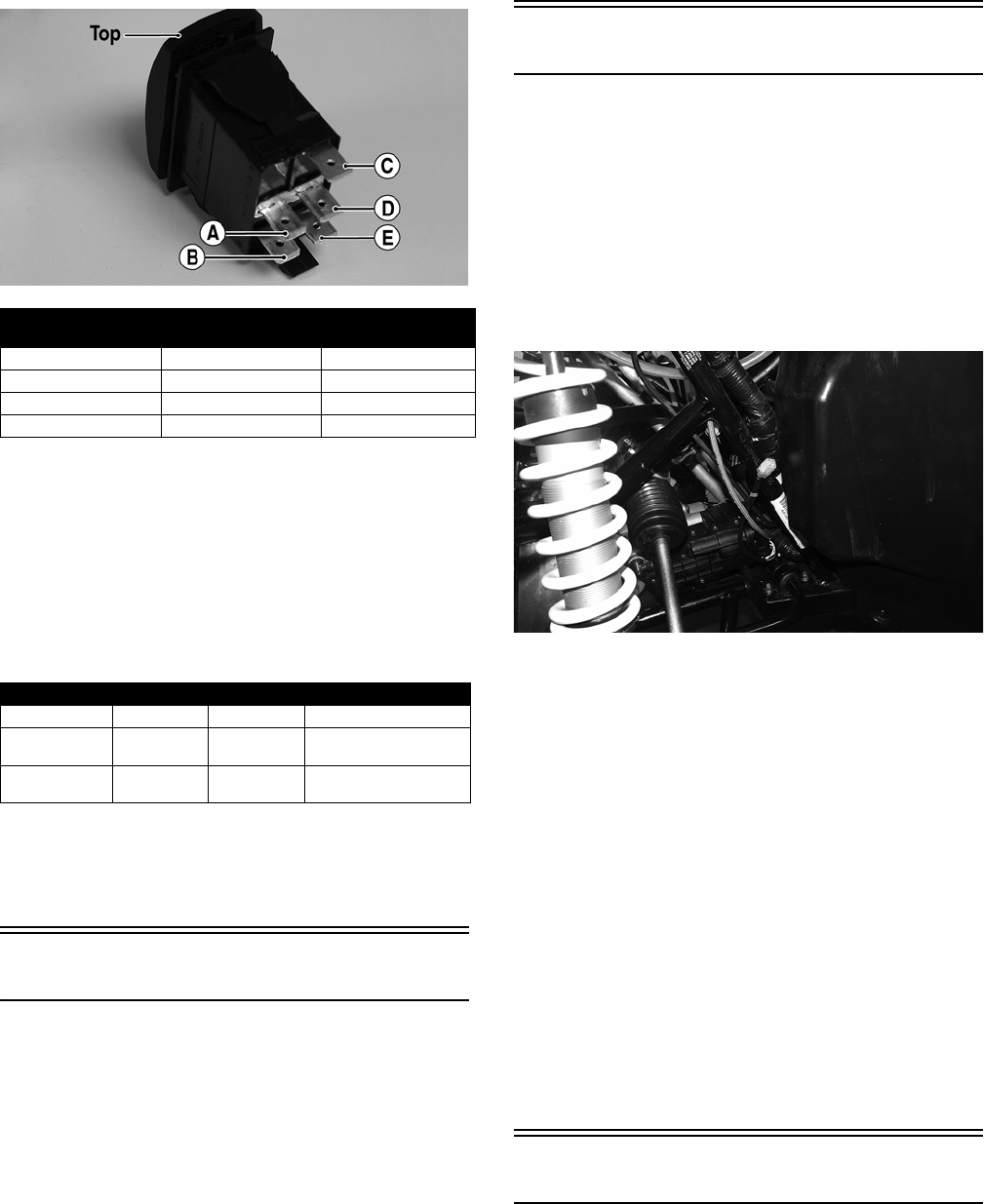
95
PR566A
VOLTAGE
NOTE: Voltage tests must be made with the switch
and the actuator connected. The meter can be con-
nected at the actuator connector using a break-out
harness or MaxiClips.
1. Turn the ignition switch to the ON position.
2. Select the DC Volts position on the tester and observe
the meter readings for each of the three switch positions.
NOTE: If the meter does not show voltages accord-
ing to the chart, make sure the front drive actuator is
plugged in; then troubleshoot the switch, ignition
fuses, battery connections, or wiring harness.
Reverse Override Switch
VOLTAGE
NOTE: To perform the following tests, the ignition
switch must be in the ON position and the transmis-
sion shifted into reverse gear.
1. Connect the red meter lead to the red/green wire and
the black meter lead to a suitable ground; then select
2WD on the drive select switch. The meter must show
approximately 1.5 DC volts.
2. Depress the reverse override switch. The meter show-
ing should not change from step 1.
3. Select 4WD on the drive select switch. The meter
must show approximately 5 DC volts.
4. Depress the reverse override switch. The meter must
show approximately 1.5 DC volts.
Front Drive Actuator
NOTE: With the engine stopped and the ignition switch
in the ON position, a momentary “whirring” sound must
be noticeable each time the drive select switch is moved
to 2WD and 4WD. Test the switch, 30 amp fuse, and wir-
ing connections prior to testing the actuator.
VOLTAGE
1. Locate the 4-wire connector for the front drive actua-
tor above the differential; then connect the red meter
lead to the orange wire using a MaxiClip.
WT561
2.
Connect the black lead to the black wire using a MaxiClip;
then select 2WD on the drive select switch.
NOTE: The black tester lead can remain connected
to the black wire for the remaining tests.
3. Turn the ignition switch to the ON position. The meter
must show battery voltage.
NOTE: If battery voltage is not shown, troubleshoot the
10 amp ignition (IGN) fuse on the power distribution
module, the ignition switch, or the main wiring harness.
4. Connect the red meter lead to the white/green wire.
The meter must show battery voltage.
5. Select 4WD on the drive select switch. The meter
must show 0 DC volts.
6. Connect the red meter lead to the white/orange wire.
The meter must show battery voltage.
7. Select LOCK on the drive select switch. The meter
must show 0 DC volts.
Stator Coil
NOTE: The cargo box must be removed for this pro-
cedure.
VOLTAGE (AC Generator - Regulated
Output)
NOTE: The battery must be at full charge for these
tests.
2WD 4WD DIFFERENTIAL
LOCK
C to E 50 ohms ± 10% C to E 50 ohms ± 10% C to E 50 ohms ± 10%
A to B Open A to B <1 ohm A to B <1 ohm
A to C Open A to C Open A to C <1 ohm
A to E Open A to B <1 ohm A to C <1 ohm
WIRE COLOR 2WD 4WD DIFFERENTIAL LOCK
Black to Orange 12.0 DC Volts 12.0 DC Volts 12.0 DC Volts
Black to White/
Green
11.5 DC Volts 0 DC Volts 0 DC Volts
Black to White/
Orange
11.5 DC Volts 11.5 DC Volts 0 DC Volts
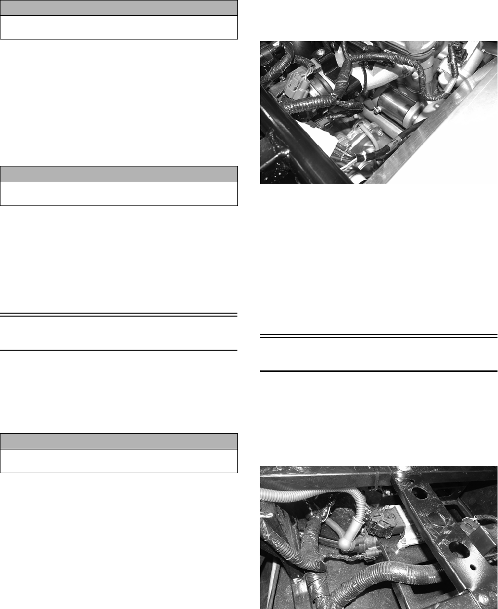
96
1. Set the meter selector to the DC Voltage position.
2. Connect the red tester lead to the positive battery post;
then connect the black tester lead to the negative bat-
tery post.
3. With the engine running at a constant 4000 RPM (with the
headlights on), the meter must show 14-15.5 DC volts.
NOTE: If voltage is lower than specified, test AC
Generator - No Load.
VOLTAGE (AC Generator - No Load)
1. Set the meter selector to the AC Voltage position.
2. Test between the three black wires for a total of three
tests.
3. With the engine running at a constant 4000 RPM, all
wire tests must be approximately 65 volts.
NOTE: If any stator coil test failed, replace the sta-
tor assembly.
RESISTANCE (AC Generator)
1. Set the meter selector to OHMS position.
2. Test between the three black wires for a total of three tests.
3. The meter reading must be less than 1 ohm.
Starter Motor
NOTE: The starter motor is not a serviceable com-
ponent. If the motor is defective, it must be replaced.
REMOVING
1. Disconnect the battery.
2. Remove the nut securing the positive cable to the
starter motor; then remove the cable from the starter.
3. Remove the two cap screws securing the starter motor
with ground wires to the crankcase; then remove the
starter motor. Account for the wiring forms and an O-ring.
INSTALLING
1. Apply a small amount of grease to the O-ring seal on the
starter motor; then install the starter into the crankcase.
Secure with two machine screws and wiring forms.
2. Secure the positive cable to the starter motor with the nut.
3. Connect the battery.
VOLTAGE
Perform this test on the starter motor positive terminal. To
access the terminal, slide the boot away.
NOTE: The ignition switch must be in the ON posi-
tion, and the shift lever in the NEUTRAL position.
1. Set the meter selector to the DC Voltage position.
2. Connect the red tester lead to the starter terminal; then
connect the black tester lead to ground.
WT555
3. With the ignition switch rotated, the meter must show
battery voltage and the starter motor should operate.
NOTE: If the meter showed battery voltage but the
starter motor did not operate or operated slowly,
inspect battery voltage (at the battery), starter motor
condition, and/or ground connections.
NOTE: If the meter showed no battery voltage,
inspect the main fuse, ground connections, starter
motor lead, battery voltage (at the battery), starter
relay, or the neutral start relay.
Starter Relay
1. Remove the driver’s seat; then using the multimeter set to
the DC Voltage position, check the relay as follows.
2. Connect the red tester lead to the positive battery
cable; then connect the black tester lead to the starter
cable connection on the starter relay. The meter must
show battery voltage.
WT560
CAUTION
Do not run the engine at high RPM for more than 10 sec-
onds.
CAUTION
Do not run the engine at high RPM for more than 10 sec-
onds.
CAUTION
Always disconnect the negative battery cable from the
battery first; then disconnect the positive cable.

97
NOTE: Make sure the ignition switch is in the ON posi-
tion and the transmission is in park.
NOTE: Verify there are no loose or corroded connec-
tions on the battery and/or starter relay.
3. Rotate the ignition switch while observing the multi-
meter. The multimeter should drop to 0 volts and the
starter should engage.
NOTE: If the starter engages but more than one volt
is indicated by the multimeter, replace the starter
relay. If no “click” is heard and the multimeter contin-
ues to indicate battery voltage, proceed to step 4.
4. Disconnect the two-wire plug from the starter relay;
then connect the red tester lead to the green wire and
the black tester lead to the yellow/green wire.
5. Depress the starter button and observe the multimeter.
NOTE: If battery voltage is indicated, replace the
starter relay. If no voltage is indicated, proceed to
Power Distribution Module (PDM) check.
Engine Control Module
(ECM)
The ECM is located beneath the driver’s seat.
NOTE: The ECM is not a serviceable component. If
the unit is defective, it must be replaced.
The ECM is rarely the cause of electrical problems; how-
ever, if the ECM is suspected, substitute another model-
compatible ECM to verify the suspected one is defective.
This EFI system has a built-in feature that will only allow
an ECM of the same part number to be used in these mod-
els. Do not attempt to substitute an ECM from a different
model as the system will not allow it to start.
Error codes can be cleared by following the procedures
located in the EFI Diagnostic System sub-section in this
section.
NOTE: If the throttle body, ECM, TPS, or ISC are
replaced, the EFI system must be synchronized. Use
the following procedure.
1. With the key off, depress accelerator pedal to Wide
Open Throttle (WOT).
2. Place the ignition key in the ON position and wait for
10 seconds.
3. Release the accelerator pedal, and wait an additional
10 seconds.
4. Turn the key to the OFF position and allow the gauge
to shut off.
Regulator/Rectifier
The regulator/rectifier is secured to the coolant overflow
tank under the hood. Verify all other charging system com-
ponents before the regulator/rectifier is replaced.
TESTING
1. Start engine and warm up to normal operating temper-
ature; then connect a multimeter (set at the DC Volt-
age position) to the battery as follows.
2. Connect the red tester lead to the positive battery post
and the black tester lead to the negative battery post.
3. Slowly increase RPM. The voltage should increase
with the engine RPM to a maximum of 15.5 DC volts.
NOTE: If voltage rises above 15.5 DC volts, the reg-
ulator is faulty or a battery connection is loose or
corroded. Clean and tighten battery connections or
replace the regulator/rectifier. If voltage does not rise,
see Stator Coil/Crankshaft Position (CKP) Sensor -
Voltage in this section. If charging coil voltage is nor-
mal, replace the regulator/rectifier.
Headlights
VOLTAGE
1. Set the meter selector to the DC Voltage position.
2. Set the light switch to the desired position; then con-
nect the black tester lead to the black wire terminal.
3. Connect the red tester lead to the yellow/black wire
terminal (high beam) or white wire terminal (low
beam). The meter must show battery voltage.
NOTE: If battery voltage is not shown in any test,
inspect the fuses on the power distribution module,
headlight switch, ignition switch, or wiring harness.
Taillight-Brakelight
VOLTAGE (Taillight)
NOTE: The ignition switch must be in the ON posi-
tion and either high beam or low beam selected on
the light switch.
1. Set the meter selector to the DC Voltage position.
2. Connect the black tester lead to the black wire; then
connect the red tester lead to the white/red wire. The
meter must show battery voltage.
VOLTAGE (Brakelight)
NOTE: The ignition switch must be in the ON posi-
tion.
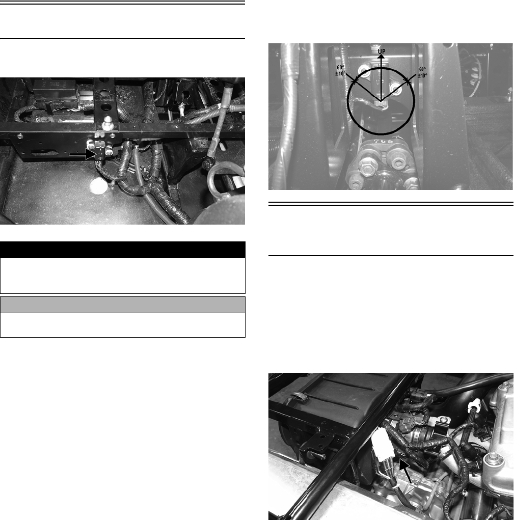
98
1. Set the meter selector to the DC Voltage position.
2. Connect the red tester lead to the red/blue wire; then
connect the black tester lead to the black wire.
3. With the brake applied, the meter must show battery
voltage.
NOTE: If the meter shows no voltage, inspect the 10
amp ignition (IGN) fuse, brakelight switch, wiring har-
ness, or connectors.
Tilt Sensor
The tilt sensor is located beneath the driver’s seat.
WT565A
SUPPLY VOLTAGE
1. Disconnect the three-wire connector from the sensor;
then select DC Voltage on the multimeter and connect
the red tester lead to the orange wire and the black tes-
ter lead to the pink/black wire.
2. Turn the ignition switch to the ON position. The mul-
timeter should read battery voltage. If battery voltage
is not indicated, check the 30-amp fuse, wiring har-
ness, or the ignition switch.
3. Remove the red tester lead and connect to the blue/
brown wire. The multimeter should read approxi-
mately 0.2 DC volts. If the specified voltage is not
indicated, check wire connections at the ECM or sub-
stitute another ECM to verify the test.
OUTPUT VOLTAGE
NOTE: MaxiClips will be required on the multimeter
leads as the following tests are made with the sensor
connected.
1. Connect the three-wire plug to the sensor; then
remove the right-side mounting screw securing the
sensor to the frame.
2. Select DC Voltage on the multimeter.
3. Connect the red tester lead to the blue/brown wire and
the black tester lead to the pink/black wire; then turn
the ignition switch ON and observe the meter. The
meter should read 0.3-1.5 DC volts.
4. Tilt the sensor 60° or more to the left and right observ-
ing the meter. The meter should read 3.0-7.0 DC volts
after approximately one second in the tilted position.
If the meter readings are not as specified, the tilt sen-
sor is defective.
NOTE: When replacing the sensor after testing
make sure the arrow is directed up.
WC159A
Throttle Position Sensor
(TPS)
NOTE: Preliminary checks may be performed on this
component using the diagnostic mode on the LCD
gauge (see EFI Diagnostic System in this section).
TESTING
1. Remove the rear fenders and cargo box. Remove
the TPS connector plug from the TPS.
WT562A
NOTE: Prior to testing the TPS, inspect the three-
wire plug connector on the main harness and the
three-pin plug on the TPS for contamination, broken
pins, and/or corrosion.
! WARNING
Incorrect installation of the tilt sensor could cause sud-
den loss of engine power which could result in loss of
vehicle control resulting in injury or death.
CAUTION
Do not drop the tilt sensor as shock can damage the
internal mechanism.
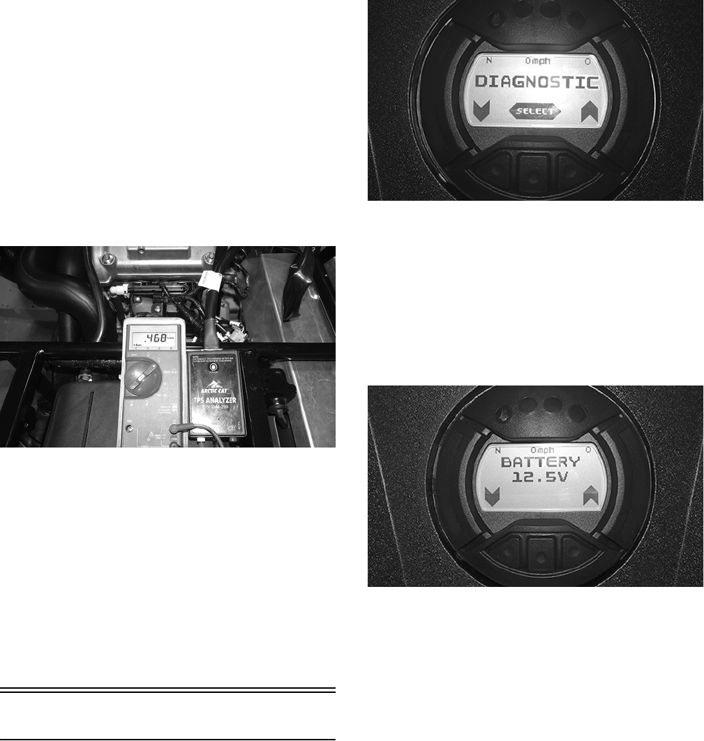
99
NOTE: If the vehicle is in warranty, removing or
adjusting the TPS will void warranty. If the TPS is
tested out of specification, the throttle body must be
replaced. If the vehicle is out of warranty, the TPS can
be adjusted.
2. Connect the TPS Multi-Analyzer Harness connec-
tor #8 to the TPS; then connect the harness to the
TPS Analyzer Tool.
3. Using a multimeter, connect the black tester lead to
the center socket (GND) on the analyzer and the red
tester lead to the white socket (VAR); then select the
DC Voltage position. The gauge should read 0.45-0.55
and at Wide-Open Throttle it should read up to
approximately 3.6.
WT563
NOTE: If the throttle body, ECM, TPS, or ISC are
replaced, the EFI system must be synchronized. Use
the following procedure.
1. With the key off, depress accelerator pedal to Wide
Open Throttle (WOT).
2. Place the ignition key in the ON position and wait for
10 seconds.
3. Release the accelerator pedal, and wait an additional
10 seconds.
4. Turn the key to the OFF position and allow the gauge
to shut off.
EFI Diagnostic System
DIGITAL GAUGE
The digital gauge can be used as a diagnostic tool for many
of the DTC’s displayed. To place the gauge into the diag-
nostic mode, use the following procedure.
1. Turn the ignition switch ON.
2. Depress and hold both left and right buttons together
for approximately three seconds until “DIAGNOS-
TIC” appears on the LCD.
WT541
3. Press the center button (SELECT) to enter diagnostic
mode; cycle the display by pressing either the left or
right button to step to the desired function.
NOTE: The gauge can be utilized dynamically
(engine running/vehicle moving) or statically (engine/
vehicle stopped).
DIAGNOSTIC MODES
Battery (BATTERY)
WT540
Display: System DC voltage.
DTC: P0562, P0563, P2531, P2532
Usage: Verify system voltage under following conditions.
1. Battery voltage with engine and accessories off (>12.2
VDC for fully charged).
2. Battery voltage with engine idling (charging = 13.8
VDC or greater).
3. Battery voltage with electrical accessories operating,
engine idling (13.5 VDC or greater).
4. Battery voltage starter cranking (10.5-11.5 VDC).
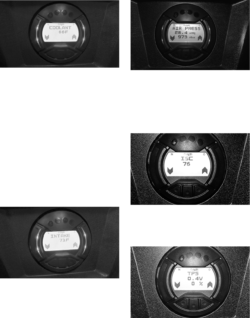
100
Coolant (COOLANT)
WT591
Display: Engine coolant temperature as measured by the
ECT sensor.
DTC: P0116, P0117, P0118, P0119
Usage: Monitor coolant temperature to verify the follow-
ing.
1. ECT sensor signal.
2. High Temperature indicator (on @ 230° F.)
3. Thermostat opening @ approximately 180° F, indi-
cated by a momentary drop or pause in the rising tem-
perature reading.
4. Fan ON @ 203° F, OFF @ 194° F:
A. fan motor
B. fan relay
C. fan fuse
D. wiring connections
5. High Temperature Rev Limiter 5000 RPM @ 230° F.
Inlet Air Temperature (INTAKE)
WT592
Display: Inlet air temperature in Fahrenheit or Celsius.
DTC: P0112, P0113, P0114
Usage: Verify correct output of IAT sensor.
NOTE: After engine has been running, IAT readings
will be higher than outside air temperature due to
engine and engine compartment heat as well as
intake manifold heating.
MAP (AIR PRESS)
WT602
Display: MAP in millibars and in./Hg.
DTC: P0107, P0108
Usage: Verify barometric pressure signal correct.
NOTE: Local barometric pressure is given in in./Hg
(inches of mercury) and millibars. The gauge should dis-
play approximately 965 millibars at 970 ft. above sea level.
Idle Step Control (ISC)
WT542
Display: ISC position
DTC: P0508, P0509
Usage: Verify correct ISC position.
TPS (TPS)
WT539
Display: TPS position (0% closed, 95-100% WOT).
DTC: P0121, P0122, P0123
Usage: Verify TPS signal and adjust throttle cable.
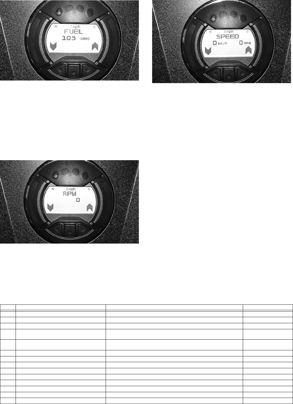
101
Fuel Sensor (FUEL)
WT545
Display: Fuel level signal from the fuel level sensor.
DTC: C1400, C1401, C1402
Usage: Check output of the fuel level sensor.*
1. Full fuel is indicated by a reading of 0-5 ohms.
2. Empty is indicated by a reading of 95-105 ohms.
* 110-500 ohms, suspect the fuel level sensor or wiring. 0-100 ohms but
no gauge indication, suspect the gauge.
Tachometer (RPM)
WT544
Display: Engine RPM
DTC: P0336, P0337, P0339
Usage: Verify engine speed signal from the following.
1. CKP (crankshaft position) sensor to ECM
2. ECM (CAN) signal to gauge (tachometer)
Speedometer (SPEED)
WT543
Display: Vehicle speed signal.
DTC: P0500
Usage: Verify speedometer sensor signal from the fol-
lowing.
1. Speed sensor to ECM.
2. ECM (CAN) signal to gauge (speedometer/odometer).
DIAGNOSTIC TROUBLE CODES
(DTC)
If an EFI or related chassis component fails or an out-of-
tolerance signal is detected by the ECM, a diagnostic trou-
ble code (DTC) will be generated in the ECM and dis-
played on the LCD. The DTC will be displayed alternately
with a wrench icon or malfunction indicator light (MIL).
The DTC will continue to flash until the malfunction is
corrected and the code cleared.
Code List
NOTE: Each of the following numerical codes will
have a one-letter prefix of C, P, or U. A “C” prefix
denotes a chassis malfunction, a “P” prefix denotes a
power train malfunction, and a “U” prefix denotes a
loss of communication with the gauge.
NOTE: Normal malfunction codes are cleared from
the LCD when the component is replaced or the mal-
function is corrected; however, intermittent codes
must be cleared as noted in the code chart.
Code Fault Description Possible Cause Fault Recovery
C0063 Tilt Sensor Circuit High Sensor or interconnect harness shorted to battery power Correct condition*
C0064 Tilt Sensor Circuit Low/SG/Open Sensor or interconnect harness open or shorted to chassis ground Correct condition*
C1263 Backup/Reverse-Light Circuit Open Bulb has failed or is disconnected or interconnect harness is open Correct condition*
C1264 Backup/Reverse-Light Circuit High Bulb has failed or is disconnected or interconnect harness shorted to
battery power
Correct condition*
C1265 Backup/Reverse-Light Circuit Low/SG Bulb has failed or is disconnected or interconnect harness shorted to
chassis ground
Correct condition*
P0030 O2 Heater Intermittent/Open Heater or interconnect harness is intermittent or open Correct condition*
P0031 O2 Heater Low/SG Heater or interconnect harness shorted to chassis ground Correct condition*
P0032 O2 Heater High/SP Heater or interconnect harness shorted to battery power Correct condition*
P0107 MAP Sensor Circuit Low/SG/Open Sensor or interconnect harness shorted to chassis ground Correct condition*
P0108 MAP Sensor Circuit High/SP Sensor or interconnect harness shorted to battery power Correct condition*
P0112 Intake Air Temp Sensor Circuit Low/SG Sensor or interconnect harness shorted to chassis ground Correct condition*
P0113 Intake Air Temp Sensor Circuit High/Open Sensor or interconnect harness open or shorted to battery power Correct condition*
P0114 Intake Air Temp Sensor Circuit Intermittent Sensor or interconnect harness intermittent Correct condition*
P0116 ECT Sensor Circuit Range/Performance Sensor producing an out-of-range voltage Correct condition*

102
High: A high voltage condition has been detected
Low: A low voltage condition has been detected
Intermittent: An intermittent circuit condition has been
detected
Open: An open circuit condition has been detected
* After correcting the condition, cycle the key switch On-Off-On
**After correcting the condition, cycle the key switch On-Off-
On, start the engine, then cycle the key switch Off-On.
P0117 ECT Sensor Circuit Low/SG Sensor or interconnect harness shorted to chassis ground Correct condition*
P0118 ECT Sensor Circuit High/Open/SP Sensor or interconnect harness open or shorted to battery power Correct condition*
P0119 ECT Sensor Circuit Intermittent Sensor or interconnect harness intermittent Correct condition*
P0121 TPS Range/Performance Sensor producing an out-of-range voltage Correct condition*
P0122 TPS Circuit Low/SG Sensor or interconnect harness shorted to chassis ground Correct condition*
P0123 TPS Circuit High Sensor or interconnect harness open or shorted to battery power Correct condition*
P0130 O2 Sensor Intermittent/Open Sensor or interconnect harness intermittent or open Correct condition*
P0131 O2 Sensor Low/SG or Air-Leak Sensor or interconnect harness shorted to chassis ground or an air-
leak exists
Correct condition*
P0132 O2 Sensor High/SP Sensor or interconnect harness shorted to battery power Correct condition*
P0171 O2 Feedback Below Minimum Correction Low fuel rail pressure, dirty fuel filter, or dirty injectors Correct condition*
P0172 O2 Feedback Exceeds Maximum Correction Excessive fuel rail pressure, MAP or temp sensors out-of-spec Correct condition*
P0219 Engine Over-Speed Condition Engine speed (RPM) has exceeded the ECM over-speed setpoint/limit Reduce engine speed
P0231 Fuel Pump Relay Circuit Low/SG/Open Relay removed or interconnect harness shorted to chassis ground Correct condition*
P0232 Fuel Pump Relay Circuit High Relay or interconnect harness shorted to battery power Correct condition*
P0233 Fuel Pump Relay Circuit Relay circuit erratic or intermittent Correct condition*
P0261 Cylinder #1 Fuel injector Circuit Low/SG Injector #1 or interconnect harness shorted to chassis ground Correct condition**
P0262 Cylinder #1 Fuel injector Circuit High Injector #1 or interconnect harness shorted to battery power Correct condition**
P0263 Cylinder #1 Fuel injector Balance/Open Injector #1 disconnected or interconnect harness is open Correct condition**
P0264 Cylinder #2 Fuel injector Circuit Low/SG Injector #2 or interconnect harness shorted to chassis ground Correct condition**
P0265 Cylinder #2 Fuel injector Circuit High Injector #2 or interconnect harness shorted to battery power Correct condition**
P0266 Cylinder #2 Fuel injector Balance/Open Injector #2 disconnected or interconnect harness is open Correct condition**
P0336 Crankshaft Angle Sensor Synchronization Sensor or interconnect harness intermittent Correct condition**
P0337 Crankshaft Angle Sensor Circuit/SG Sensor or interconnect harness shorted to chassis ground Correct condition**
P0339 Crankshaft Angle Sensor Intermittent/Erratic Sensor or interconnect harness intermittent Correct condition**
P0340 Camshaft Angle Sensor Synchronization Sensor or interconnect harness intermittent Correct condition**
P0341 Camshaft Angle Sensor Circuit/SG Sensor or interconnect harness shorted to chassis ground Correct condition**
P0342 Camshaft Angle Sensor Intermittent/Erratic Sensor or interconnect harness intermittent Correct condition**
P0480 Fan Relay Control Circuit Relay erratic or intermittent Correct condition*
P0484 Fan Relay Control Circuit High Relay or interconnect harness shorted to battery power Correct condition*
P0485 Fan Relay Control Circuit Low/SG/Open Fan fuse has blown, fan relay removed, or interconnect harness
shorted to chassis ground
Correct condition*
P0500 Vehicle Speed-Sensor Sensor circuit signal intermittent or missing Correct condition*, start
and drive the vehicle*
P0508 Idle Air Control System Circuit Low/SG IAC interconnect harness shorted to chassis ground Correct condition*
P0509 Idle Air Control System Circuit High/Open IAC disconnected or the interconnect harness shorted to battery power Correct condition*
P0520 Engine Oil Sensor/Switch Sensor or interconnect harness erratic or intermittent Correct condition*
P0562 System Voltage Low Battery charge condition low or the regulator/rectifier output low Correct condition*
P0563 System Voltage High Battery cable connections are loose or regulator/rectifier output high Correct condition*
P0601 ECM CAN Communication Shutdown Intermittent CAN connections or unstable CAN conditions have
caused the ECM to temporarily shutdown CAN communication
Correct CAN communi-
cation issue*
P0615 Starter Relay Circuit Start switch/button, starter relay, gearswitch or interconnect harness
erratic or intermittent
Correct condition*
P0616 Starter Relay Circuit Low Start switch/button, starter relay or interconnect harness intermittent or
shorted to chassis ground
Correct condition*
P0617 Starter Relay Circuit High Start switch/button, starter relay or interconnect harness intermittent or
shorted to battery power
Correct condition*
P0630 VIN Not Programmed or Incompatible Verify the LCD gauge and ECM part numbers are correct for the vehi-
cle model number and VIN
Correct gauge and ECM
VIN compatibility issue*
P0642 Sensor Power Circuit Low One or more of the sensors defective or shorted to chassis ground Correct condition*
P0643 Sensor Power Circuit High One or more of the sensors defective or shorted to battery power Correct condition*
P2300 Ignition Coil #1 Primary Circuit Low/SG/Open Ignition coil #1 or interconnect harness open or shorted to chassis
ground
Correct condition**
P2301 Ignition Coil #1 Primary Circuit High Ignition coil #1 or interconnect harness shorted to battery power Correct condition**
P2303 Ignition Coil #2 Primary Circuit Low/Open Ignition coil #2 or interconnect harness open or shorted to chassis
ground
Correct condition**
P2304 Ignition Coil #2 Primary Circuit High Ignition coil #2 or interconnect harness shorted to battery power Correct condition**
P2531 Ignition Switch Circuit Low Battery charge condition low or the regulator/rectifier output low Correct condition*
P2532 Ignition Switch Circuit High Battery cable connections are loose or regulator/rectifier output high Correct condition*
U0155 LCD Gauge to EFI ECM CAN Communication
Lost
Gauge CAN circuit or interconnect harness intermittent or has failed Correct condition*
U1000 Vehicle Not Registered or Invalid PIN Entered An invalid registration PIN has been entered Enter the correct regis-
tration PIN*
U1001 Vehicle Not Registered and Vehicle Limits
Enabled
An invalid registration PIN has been entered Enter the correct regis-
tration PIN*
FUEL
OFF
Tilt Sensor Activation Code Sensor activated Restore the vehicle chas-
sis to an upright position*
Code Fault Description Possible Cause Fault Recovery
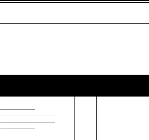
103
RPM Limiter
NOTE: This vehicle is equipped with an ECM that
interrupts the ignition when maximum RPM is
approached (see table). When the RPM limiter is acti-
vated, it could be misinterpreted as a high-speed mis-
fire.
Gear Reverse
Park/
High/
Neutral/
Low
Fail-Safe
Mode
Incorrect
ECU/
Gauge
(P0630)
Warranty
Registration
2WD
5000
7750 5000 6750 4500
4WD
4WD Lock
2WD Override 6000
4WD Override
7750
Differential-Lock
Override

104
Troubleshooting
Problem: Spark absent or weak
Condition Remedy
1. Ignition coil defective
2. Spark plug(s) defective
3. CKP sensor defective
4. ECM defective
1. Replace ignition coil
2. Replace plug(s)
3. Replace CKP sensor
4. Replace ECM
Problem: Spark plug fouled with carbon
Condition Remedy
1. Gasoline incorrect
2. Air cleaner element dirty
3. Spark plug(s) incorrect (too cold)
4. Valve seals cracked - missing
5. Oil rings worn - broken
1. Change to correct gasoline
2. Clean element
3. Replace plug(s)
4. Replace seals
5. Replace rings
Problem: Spark plug electrodes overheat or burn
Condition Remedy
1. Spark plug(s) incorrect (too hot)
2. Engine overheats
3. Spark plug(s) loose
1. Replace plug(s)
2. Service cooling system
3. Tighten plug(s)
Problem: Battery does not charge
Condition Remedy
1. Lead wires/connections shorted - loose - open
2. Stator coils shorted - grounded - open
3. Regulator/rectifier shorted
1. Repair - replace - tighten lead wires
2. Replace stator coils
3. Replace regulator/rectifier
Problem: Battery charges, but charging rate is below the specification
Condition Remedy
1. Lead wires shorted - open - loose (at terminals)
2. Stator coils grounded - open
3. Regulator/rectifier defective
4. Cell plates (battery) defective
1. Repair - tighten lead wires
2. Replace stator coils
3. Replace regulator/rectifier
4. Replace battery
Problem: Magneto overcharges
Condition Remedy
1. Battery short circuited
2. Regulator/rectifier defective
3. Regulator/rectifier poorly grounded
1. Replace battery
2. Replace regulator/rectifier
3. Clean - tighten ground connection
Problem: Charging unstable
Condition Remedy
1. Lead wire intermittently shorting
2. Magneto internally shorted
3. Regulator/rectifier defective
1. Replace lead wire
2. Replace stator coil
3. Replace regulator/rectifier
Problem: Starter does not engage
Condition Remedy
1. Battery charge low
2. Switch contacts defective
3. Starter motor brushes not seating
4. Starter relay defective
5. Wiring connections loose - disconnected
6. Start-in-gear/neutral relay defective
1. Recharge - replace battery
2. Replace switch
3. Replace starter
4. Replace relay
5. Connect - tighten - repair connections
6. Replace relay
Problem: Battery “sulfation” (Acidic white powdery substance or spots on surfaces of cell plates)
Condition Remedy
1. Charging rate too low - too high
2. Battery discharged
1. Replace battery
2. Charge battery
Problem: Battery discharges too rapidly
Condition Remedy
1. Charging system (charging operation) not set properly
2. Cell plates overcharged - damaged
3. Battery short-circuited
4. Electrical load too high
1. Check AC generator - regulator/rectifier - circuit connections
2. Replace battery - correct charging system
3. Replace battery
4. Reduce load
Problem: Battery polarity reversed
Condition Remedy
1. Battery incorrectly connected 1. Reverse connections - replace battery
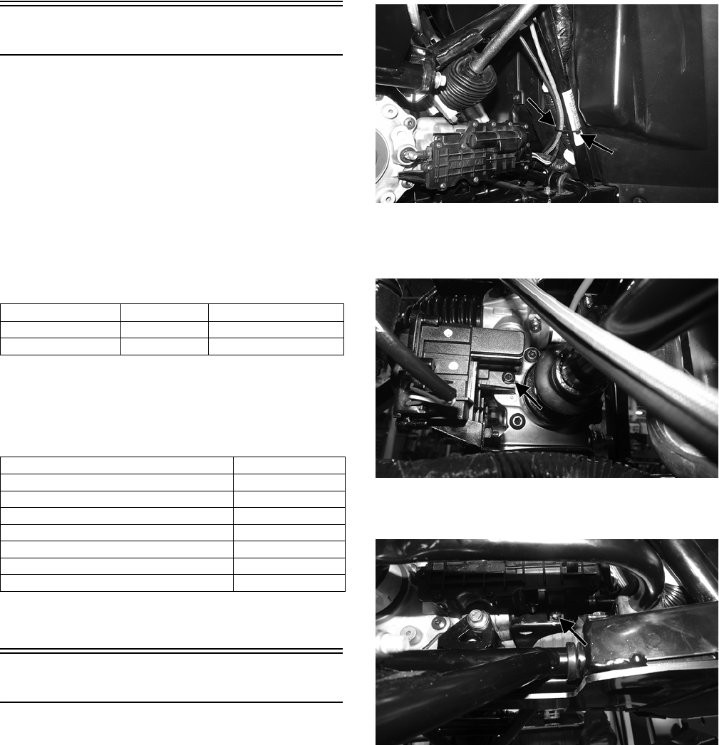
105
Drive and Brake Systems
The following drive system components should be
inspected periodically to ensure proper operation.
A. Spline lateral movement (slop).
B. Coupling cracked, damaged, or worn.
C.Carrier bearing smooth rotation and bearing support
tight.
GENERAL INFORMATION
The die-cast aluminum housings have been assembled
with thread-rolling screws (trilobular). When assembling
with these screws, start the screws carefully into the hous-
ing; then use the following torque values.
SPECIAL TOOLS
A number of special tools must be available to the techni-
cian when performing service procedures in this section.
Refer to the current Special Tools Catalog for the appropri-
ate tool description.
NOTE: Special tools are available from the Arctic
Cat Service Department.
Front Drive Actuator
NOTE: The actuator is not a serviceable compo-
nent. If it is defective, it must be replaced.
NOTE: The actuator will operate only when the igni-
tion switch is in the ON position.
The front drive actuator is located on the left side of the
front differential input housing. With the engine stopped
and the ignition switch in the ON position, a momentary
“whirring” sound can be heard each time the drive select
switch is shifted. If no sound is heard, see Electrical Sys-
tem. If the actuator runs constantly or makes squealing or
grinding sounds, the actuator must be replaced.
REMOVING
1. Select LOCK on the drive select switch; then discon-
nect the connector on the actuator harness.
WT504A
2. Remove the floor; then using a T-30 torx wrench,
remove the mounting cap screw from the driveshaft
side of the actuator.
WT529A
3. Remove the mounting cap screw from above the actu-
ator on the suspension side.
WT530A
4. Loosen but do not remove the mounting cap screw at
the front of the actuator; then slide the actuator to the
rear enough to clear the slotted mounting tab and the
selector shaft. Remove from the left side.
Size New Housing Reassembled Housing
M6 (Torx T-30 Recess) 9 ft-lb 8 ft-lb
M8 (Torx T-40 Recess) 28 ft-lb 23 ft-lb
Description p/n
Backlash Measuring Tool 0544-010
CV Boot Clamp Tool 0444-120
Hose Clamp Pliers 0644-545
Internal Hex Socket 0444-104
Pinion Gear/Shaft Removal Tool 0444-127
Gear Case Seal Installer Tool 0444-224
Transaxle Tool Kit 0544-030
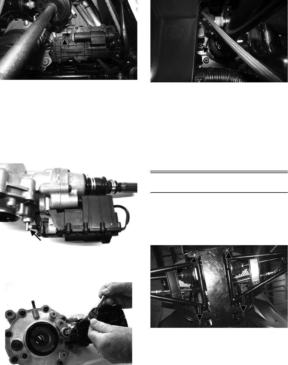
106
WT531A
INSTALLING
1. Lubricate the O-rings on the actuator; then ensure all
mounting surfaces are clean and free of debris.
2. Align the actuator with the selector shaft and slide it
forward onto the shaft taking care to engage the cap
screw in the slot of the front mounting tab.
NOTE: Make sure to properly align the differential
lock actuator lever with the hole in the differential
lock plunger.
GC002A
3. While holding the actuator firmly forward, tighten the
front cap screw to hold the actuator in place; then
install but do not tighten the two remaining cap
screws.
GC001
4. Loosen the front cap screw; then tighten the cap screw
on the driveshaft side to 36 in.-lb.
WT532A
NOTE: It is important to tighten this cap screw while
the others are loose to ensure proper seating of the
actuator.
5. Tighten the remaining cap screws to 36 in.-lb; then
connect the electrical plug to the main harness.
6. Turn the ignition switch to the ON position and check
the operation by shifting the drive select switch sev-
eral times.
7. Secure the wiring harness to the frame with a nylon
cable tie; then install the floor.
Front Differential
REMOVING
1. Lift and support the vehicle with a stand that allows
access to the front suspension with the vehicle off the
floor.
2. Remove the front skid plate.
WT499A
3. Remove the front differential drain plug and drain the
gear case lubricant into a suitable pan. Account for a
rubber O-ring.
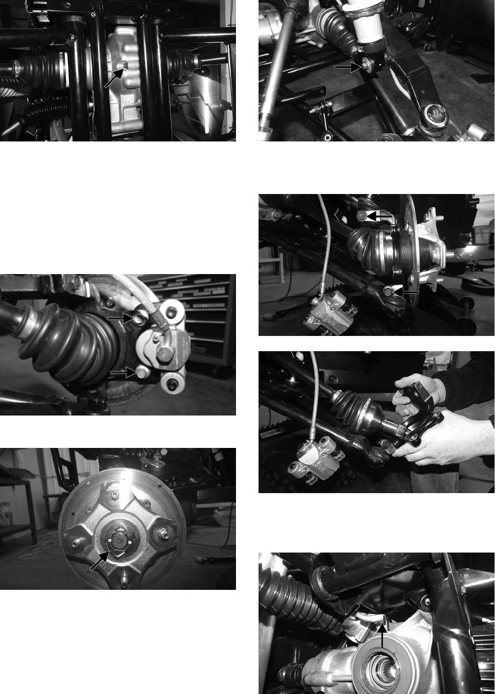
107
WT500A
NOTE: After all lubricant is drained, install the drain
plug and tighten to 45 in.-lb.
4. Remove the steering wheel and dash; then remove the
steering post (see Steering/Frame/Controls).
5. Remove the rack and pinion assembly; then remove
the front wheels.
6. Remove and discard the “patch-lock” cap screws
securing the brake calipers.
WT287A
7. Remove the hub nut and discard the cotter key.
WT328A
8. Remove and discard the “patch-lock” cap screw
securing the shock absorber to the upper A-arm and
retain the washer. Remove the shock absorber from
the upper A-arm.
WT498A
9. Remove and discard the upper ball joint cap screw and
rotate the knuckle downward and away from the drive
axle.
WT329A
WT332
10. Using a suitable strap, swing the upper A-arm and
shock absorber upward; then secure them to the frame.
11. Remove the axles and front differential vent hose.
WT503A
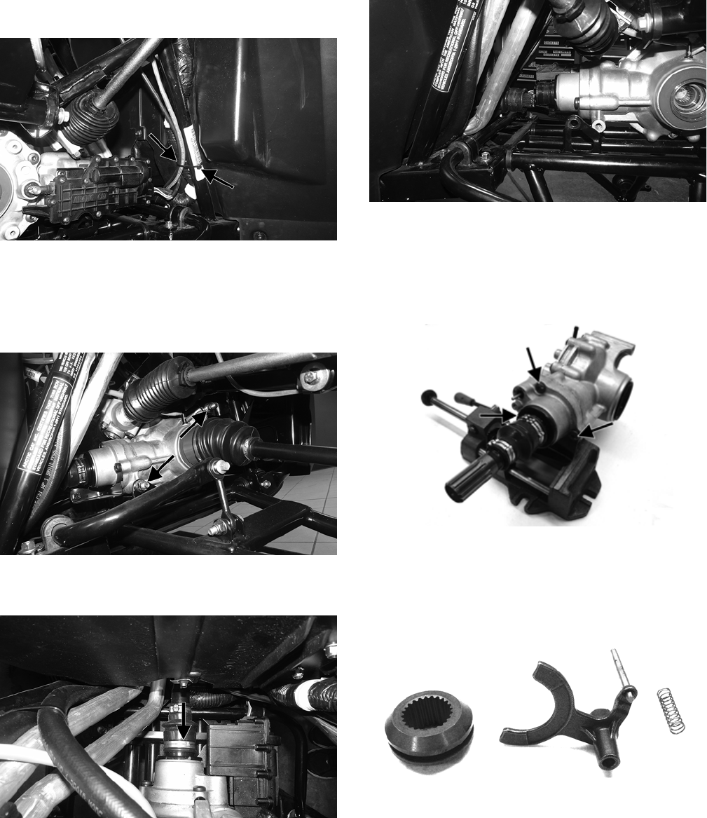
108
12. Cut the cable tie securing the actuator plug to the
frame; then disconnect the actuator.
WT504A
NOTE: Note the position of the cable ties for assem-
bly purposes.
13. Remove the cap screws and spacers securing the front
differential to the frame. Discard the nuts.
WT423A
14. Remove the clamp securing the boot on the output
shaft of the front differential.
WT422A
15. Pull the front differential forward until the driveshaft
splines are free from the differential.
WT502
16. Remove the differential from the vehicle from the left
side.
Disassembling Input Shaft
1. Using a T-40 torx wrench, remove the cap screws
securing the pinion housing.
GC004A
2. Using a rubber mallet, remove the housing. Account
for a gasket. Remove the fork, collar, and spring. Note
the location of all the components for assembling pur-
poses.
GC015
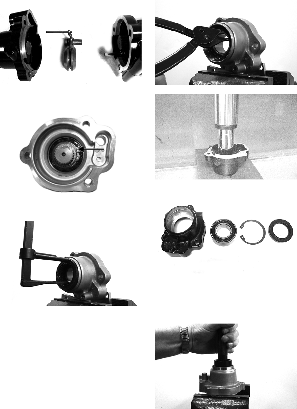
109
CD106
3. Remove the snap rings from the input shaft; then
remove the input shaft from the pinion housing.
GC009A
4. Using a seal removal tool, remove the input shaft seal.
Account for a spacer.
GC010
5. Remove the snap ring securing the input shaft bearing;
then place the pinion housing in a press and remove
the bearing.
GC011
AF984
KX219
Assembling Input Shaft
1. Place the pinion housing in a press and install the
input shaft bearing. Secure the bearing with the exist-
ing snap ring making sure the sharp edge of the snap
ring faces to the outside.
GC012
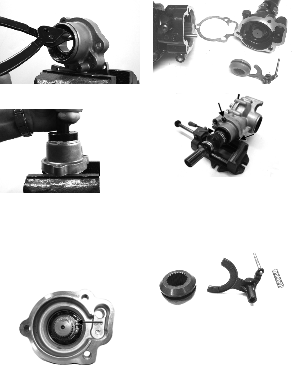
110
GC011
2. Install the input shaft seal making sure it is fully
seated in the edge of the housing.
GC014
3. Lubricate the input shaft with High-Performance #2
Molybdenum Disulphide Grease packing the boot ribs
and splines; then assemble allowing excess grease to
freely escape. Slight pressure on the boot will be pres-
ent during assembly. Secure with new clamps.
NOTE: Any time drive splines are separated, clean
all splines with parts-cleaning solvent and dry with
compressed air; then lubricate with recommended
grease.
4. Install the input shaft into the pinion housing; then
secure in the bearing with a circlip.
GC009A
5. Place the pinion housing with new gasket onto the dif-
ferential housing; then secure with existing cap
screws. Tighten to 23 ft-lb.
NOTE: If a new differential housing is being
installed, tighten the cap screws to 28 ft-lb.
KX209
GC004A
Disassembling Differential Assembly
NOTE: This procedure can be performed on a rear
gear case.
1. Using a T-40 torx wrench, remove the cap screws
securing the pinion housing. Account for the coupler,
fork, and spring (differential only).
GC015
2. Using a T-40 torx wrench, remove the cap screws
securing the differential cover.
3. Using a plastic mallet, tap lightly to remove the differ-
ential cover. Account for an O-ring.
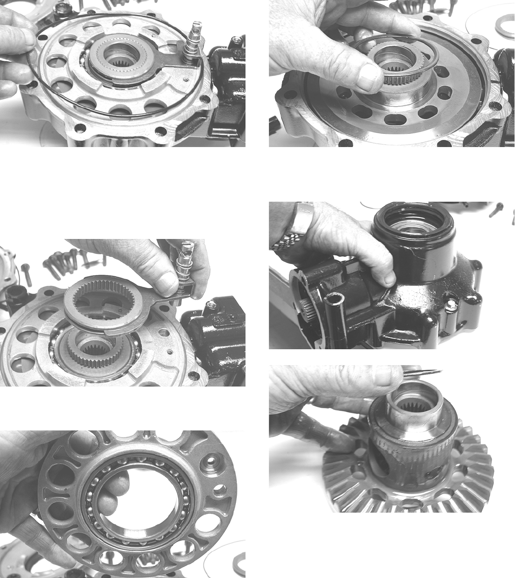
111
KX174
NOTE: If the cover is difficult to remove, pry on the
cover in more than one recessed location.
4. Remove the splined coupler, shifter fork, pin, and
spring of the differential lock assembly and set aside.
Note position of parts for assembling purposes.
KX175
5. Remove the left differential bearing flange assembly
and account for a shim. Mark the shim as left-side.
KX177
KX178
6. Place the differential with the open side down; then
lift the housing off the spider assembly. Account for
shim(s) and mark as right-side.
KX179
KX181
Disassembling Pinion Gear
1. Remove the internal snap ring securing the pinion
bearing in the housing.
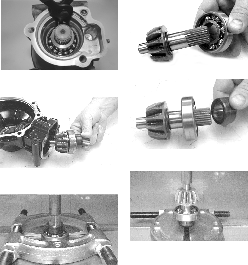
112
WC430
2. Using the Pinion Gear/Shaft Removal Tool and a ham-
mer, remove the pinion gear from the gear case hous-
ing.
CC878
3. Secure the pinion gear in a bearing puller; then
remove the pinion bearing using a press. Account for a
collar and a bearing.
CC879
4. Remove any reusable parts from the gear case hous-
ing; then discard the housing and lock collar.
Assembling Pinion Gear
1. Install the bearing onto the pinion shaft. Install the
pinion shaft collar.
CC882
CC883
2. Place the pinion assembly in a bearing puller; then
install the bearing using a press.
CC884
3. Using a propane torch, heat the gear case housing to
approximately 200° F; then install the pinion assem-
bly.
4. Install the internal snap ring with the sharp side
directed away from the bearing.
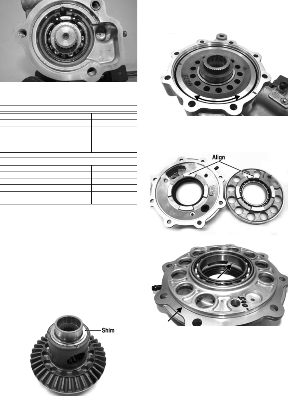
113
WC429
Shimming Procedure/Shim Selection
It is very important to adjust bevel gears for the proper
running tolerances. Gear life and gear noise are greatly
affected by these tolerances; therefore, it is very important
to properly adjust any gear set prior to final assembly.
The following procedure can be used on both front differ-
ential or rear drive gear case.
NOTE: All bearings must be installed in the gear case
and the pinion properly installed before proceeding.
Backlash
NOTE: Always set backlash prior to any other shim-
ming.
1. Install the existing shim or a 0.051-0.055-in. shim on
the gear case side of the ring gear assembly.
GC031A
2. Install the ring gear with shim in the gear case; then
while holding the pinion stationary, rock the ring gear
forward and back to determine if any backlash exists.
If no backlash exists, install a thicker shim and
recheck.
GC036A
3. Install the bearing flange onto the gear case cover
making sure the alignment/locating pin engages the
locating hole in the cover; then make sure the bearing
flange is completely seated in the cover.
GC032A
GC033A
4. Install the existing shim or a 0.063 in. shim on the cover
side of the ring gear; then place the assembled gear case
cover onto the gear case and secure with three cap
screws. Tighten evenly using a crisscross pattern.
Case-Side Shims (Backlash)
p/n mm in.
0402-405 1.3 0.051
0402-406 1.4 0.055
0402-407 1.5 0.059
0402-408 1.6 0.063
0402-409 1.7 0.067
Cover-Side Shims (Ring Gear End-Play)
p/n mm in.
1402-074 1.3 0.051
1402-075 1.4 0.055
1402-076 1.5 0.059
1402-077 1.6 0.063
1402-078 1.7 0.067
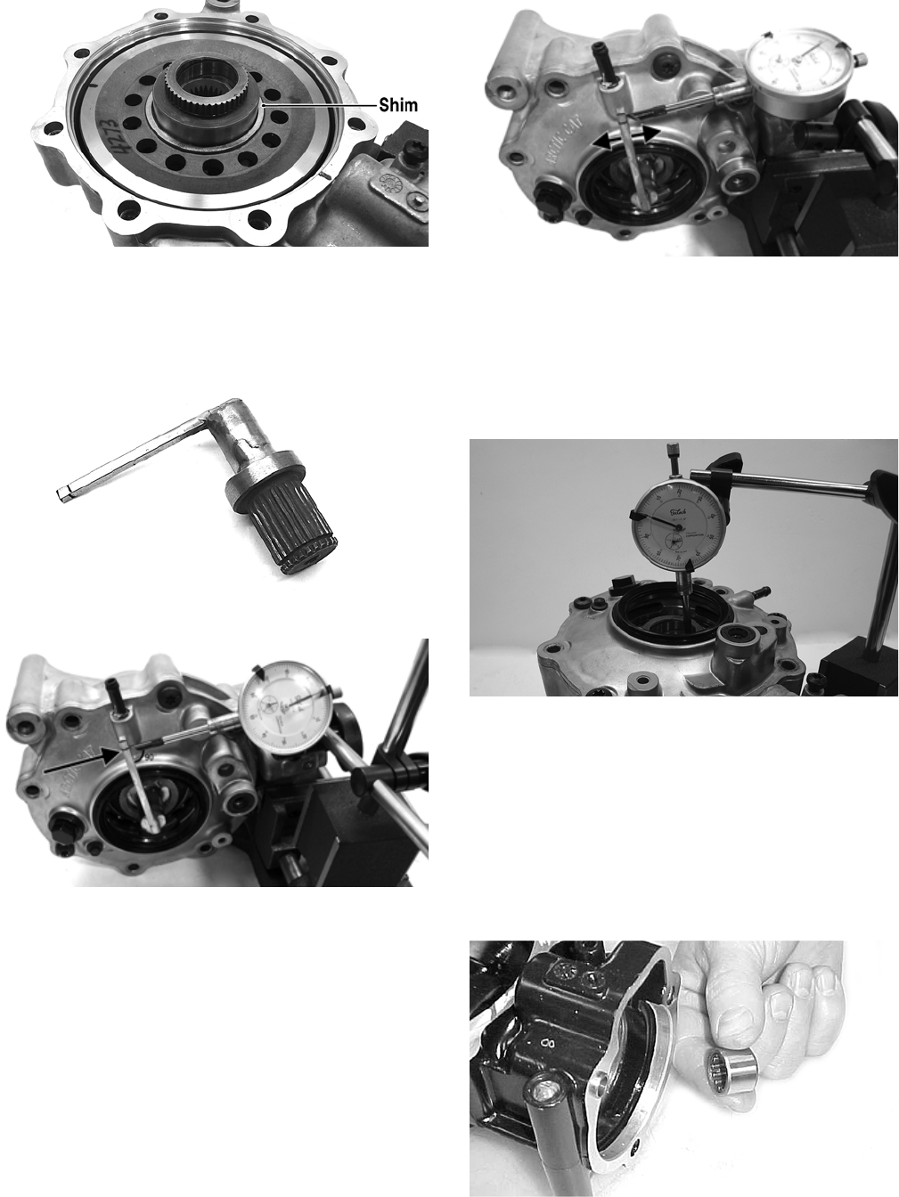
114
GC036B
5. Place the Backlash Measuring Tool into the splines of
the ring gear and install a dial indicator making sure it
contacts the gauge at a 90° angle and on the index
mark.
GC040
GC039A
6. Zero the dial indicator; then while holding the pinion
stationary, rock the ring gear assembly forward and
back and record the backlash. Backlash must be
0.011-0.015 in. If backlash is within specifications,
proceed to Ring Gear End-Play. If backlash is not
within specifications, increase shim thickness to
increase backlash or decrease shim thickness to
decrease backlash.
NOTE: Higher backlash settings usually result in
quieter gear operation.
GC037A
Ring Gear End-Play
After correcting backlash, ring gear end-play can be
adjusted. To adjust end-play, use the following procedure.
1. Secure the gear case in a holding fixture with the
cover side up; then install a dial indicator contacting
the ring gear axle flange.
GC035
2. Zero the dial indicator; then push the ring gear toward
the dial indicator and release. End-play should be
0.004-0.008 in.
3. To increase end-play, decrease the shim thickness. To
decrease end-play, increase the shim thickness.
NOTE: Once proper backlash and end play are
established, the gear case can be assembled (see
Assembling Differential Assembly in this sub-sec-
tion).
CC888
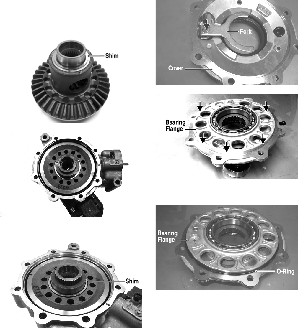
115
Assembling Differential Assembly
1. With the pinion gear and new bearings installed, place
the selected (backlash) shim on the gear case side of
the ring gear with the chamfered side toward the ring
gear; then install into gear case/differential housing.
GC031A
GC020
2. Place the selected (end-play) shim, chamfered side
toward the gear, onto the cover side of the ring gear.
GC036B
NOTE: The spider and ring gear assembly must be
replaced as a complete unit.
3. Assemble the fork and sliding collar into the cover
assembly; then install the left bearing flange/bearing
assembly and seat firmly into the cover.
CF266A
CF267A
4. Apply a light coat of Gear Case Sealant to the cover
face and O-ring.
CF275A
5. Install the cover with existing cap screws (coated with
green Loctite #270). Tighten the cap screws evenly to
23 ft-lb.
NOTE: Grease can be applied to the O-ring for ease
of assembling.
NOTE: If a new housing is being installed, tighten
the cap screws to 28 ft-lb.
6. Install the shift fork shaft w/spring into the housing
making sure the shaft O-ring is positioned to the
inside.
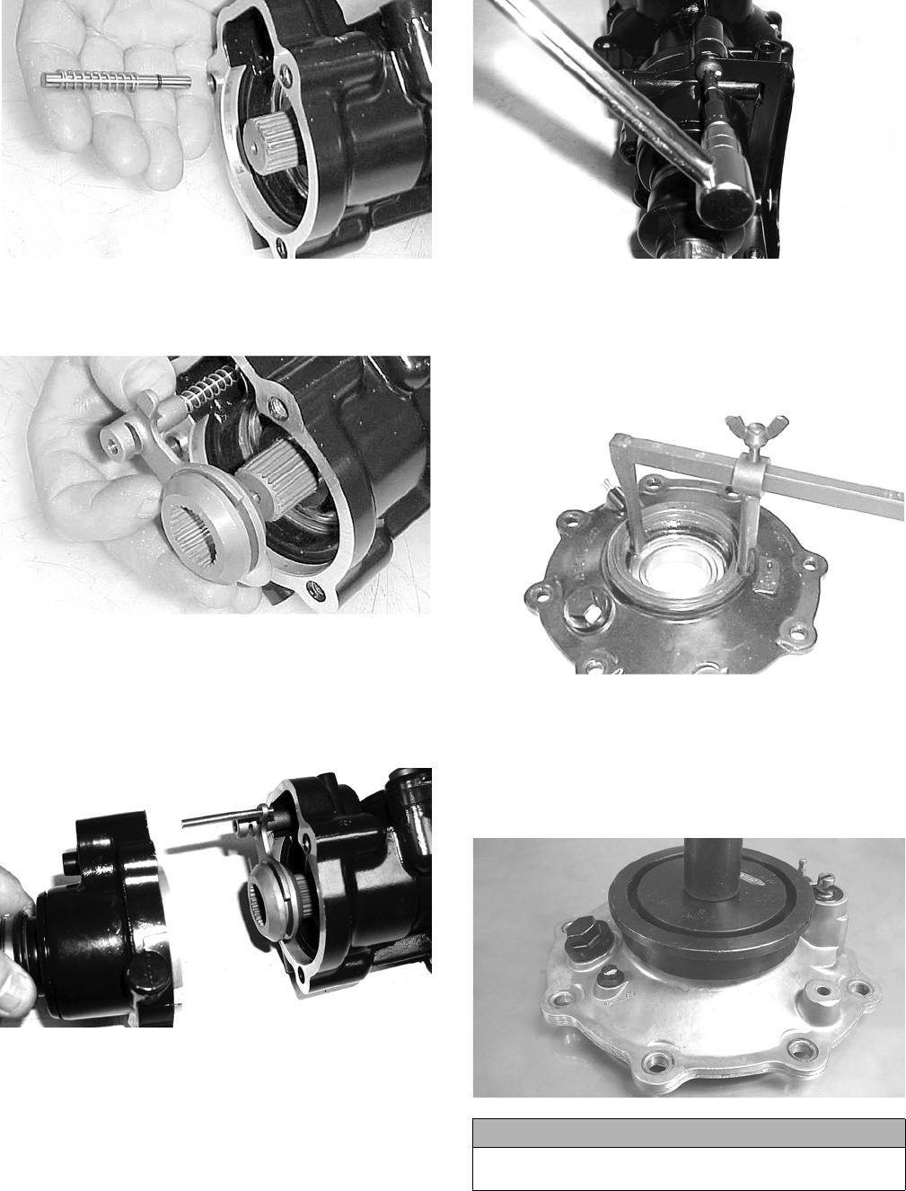
116
CC892
7. Install the shift fork assembly making sure the fork leg
is facing upward. Apply a small amount of oil to the
gasket; then install the gasket.
CC893
8. Place the input shaft assembly onto the gear case
housing; then secure with the existing cap screws.
Tighten to 23 ft-lb.
NOTE: If a new housing is being installed, tighten
the cap screws to 28 ft-lb.
CD103
CD110
Removing/Installing Axle Seal
NOTE: This procedure can be performed on a rear
gear case.
1. Remove the seal using a seal removal tool.
CC899
NOTE: Prior to installing the seal, apply High-Per-
formance #2 Molybdenum Disulphide grease to the
seal outside diameter.
2. Using Gear Case Seal Installer Tool, evenly press the
seal into the cover bore until properly seated.
CF278
3. Repeat steps 1-2 for the opposite side.
CAUTION
Make sure the tool is free of nicks or sharp edges or
damage to the seal may occur.
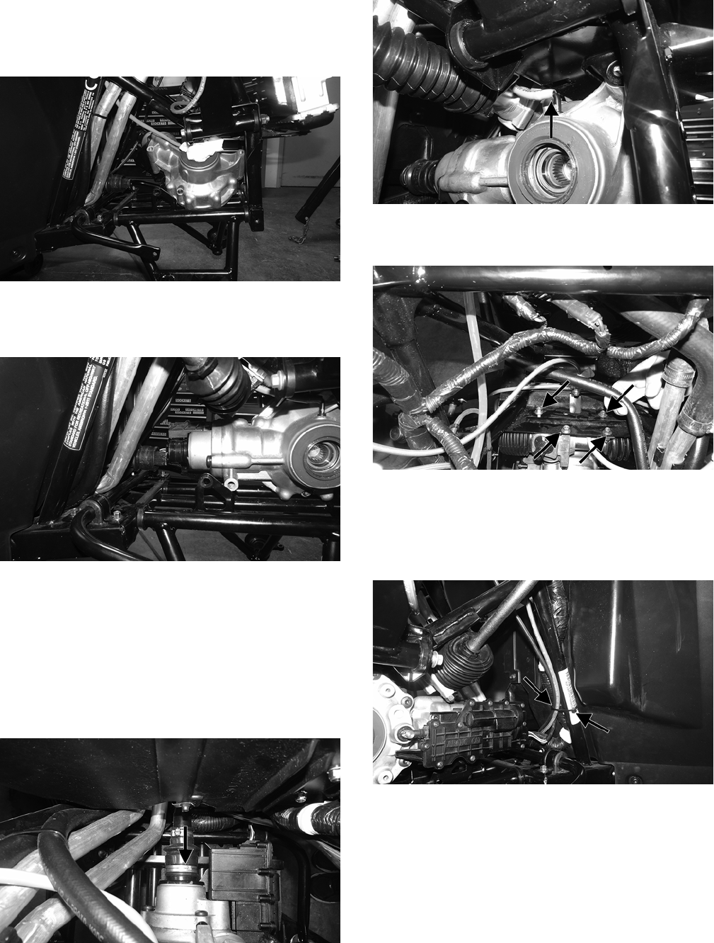
117
INSTALLING
1. From the right side of vehicle, place the differential
into the vehicle (actuator side down); then maneuver it
into the mounting brackets.
WT501
2. Slide the differential towards the front of the vehicle
to align the driveshaft; then apply molybdenum grease
and slide the differential rearward onto the driveshaft.
WT502
3. Install the existing cap screws and spacers securing
the front differential to the frame. Using new cap lock
nuts, tighten to 38 ft-lb.
NOTE: The spacers go between the mounting
brackets and the front differential on the left side of
the differential.
4. Install the boot clamp securing the boot to the output
shaft of the front differential.
WT422A
5. Install the differential vent hose.
WT503A
6. Install the rack and pinion assembly. Using new lock
nuts, secure it to the frame and tighten to 25 ft-lb.
WT369A
7. Install the steering shaft, dash, and steering wheel.
8. Install the drive axles.
9. Connect the actuator harness and secure it with cable
ties.
WT504A
10. Install the axle into the knuckles; then swing the
knuckles upward and engage the ball joint of the
upper A-arm into the knuckle. Using a new “patch-
lock” cap screw, tighten to 35 ft-lb.
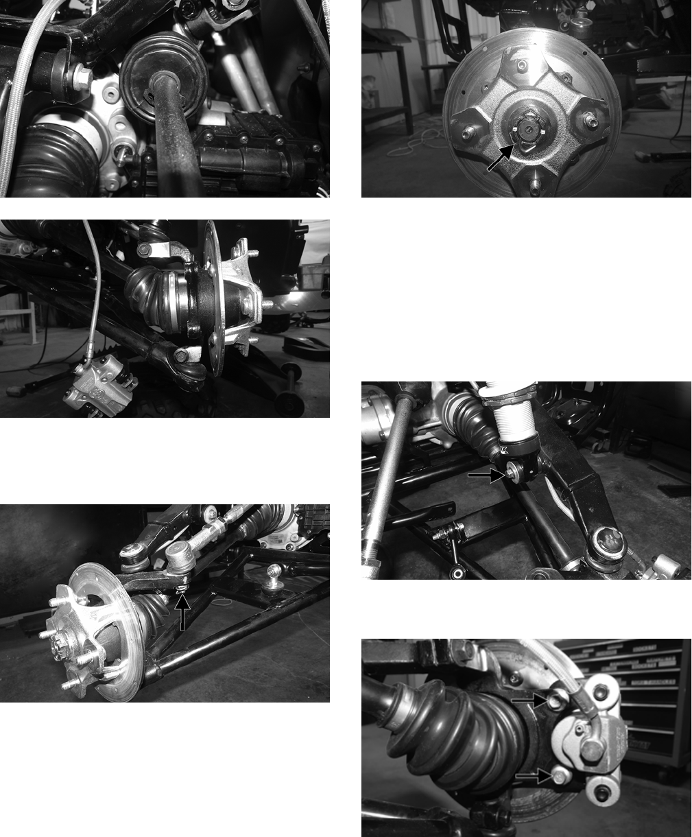
118
WT333
WT329
11. Install the tie rod end and secure it with the castle nut
(coated with red Loctite #271). Tighten to 55 ft-lb;
then install a new cotter pin and spread the pin to
secure the nut.
WT330A
12. Install the hub assembly and secure with the hub nut.
Tighten to 200 ft-lb. Install a new cotter pin and
spread the pin to secure the nut.
WT328A
NOTE: During assembly, new cotter pins should
always be used.
NOTE: If the cotter pin cannot be inserted due to
misalignment of the hole and the slots in the nut,
always tighten the nut until it is properly aligned.
13. Using a new “patch-lock” cap screw and the existing
washer, secure the shock absorber to the upper A-arm
and tighten to 25 ft-lb.
WT498A
14. Using new “patch-lock” cap screws, secure the brake
caliper to the brake disc. Tighten to 20 ft-lb.
WT287A
15. Add SAE approved 80W-90 hypoid differential lubri-
cant until it is visible at the level plug.
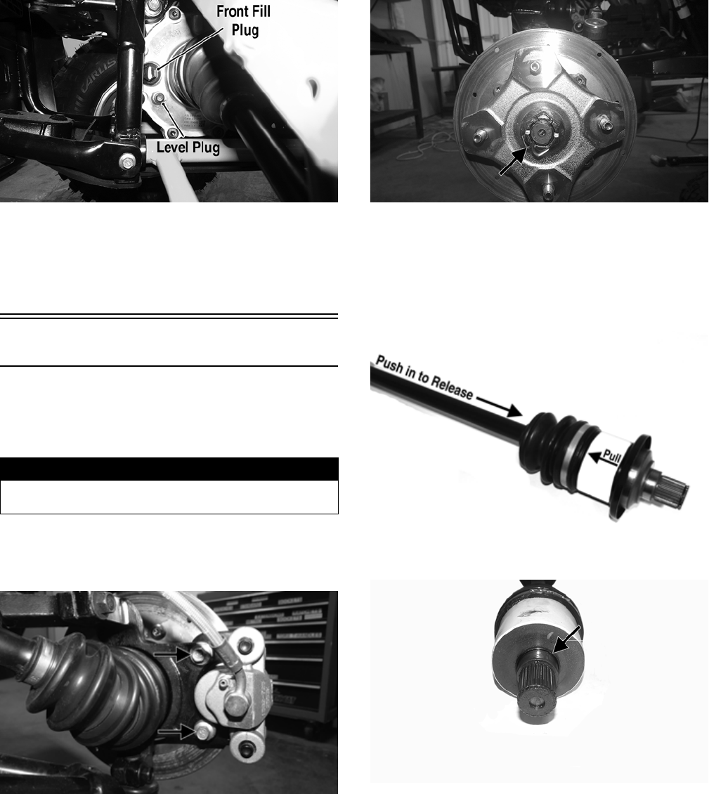
119
WT041A
16. Install the plugs (with O-rings); then tighten the fill
plug to 16 ft-lb and the level plug to 45 in.-lb.
17. Install the front skid plate; then install the wheels and
tighten to 40 ft-lb (steel wheel) or 80 ft-lb (aluminum
wheel).
Drive Axles
REMOVING REAR DRIVE AXLE
1. Secure the vehicle on a support stand to elevate the
wheels.
2. With the vehicle in park, remove the wheels.
3. Remove and discard the “patch lock” cap screws
securing the brake calipers.
WT287A
4. Remove hub nut and discard the cotter key.
WT328A
5. Remove and discard the upper ball joint cap screw and
rotate the knuckle downward away from the drive
axle.
6. Place a drain pan under the vehicle to contain any oil
leakage; then pushing the axle shaft in, pull the axle
assembly from the transaxle.
PR729C
7. Account for the rubber O-ring.
WT509A
REMOVING FRONT DRIVE AXLE
NOTE: For removing a front drive axle, see Front
Differential in this section.
CLEANING AND INSPECTING
AXLES
NOTE: Always clean and inspect the drive axle com-
ponents to determine if any service or replacement is
necessary.
! WARNING
Make sure the vehicle is solidly supported on the sup-
port stand to avoid injury.
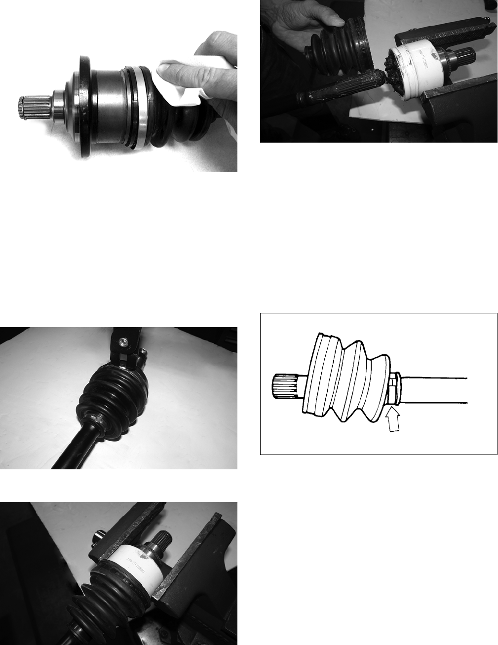
120
1. Using a clean towel, wipe away any oil or grease
from the axle components.
CD019
2. Inspect boots for any tears, cracks, or deterioration.
NOTE: If a boot is damaged in any way, it must be
replaced with a boot kit.
DISASSEMBLING AXLES
NOTE: Only the boots are serviceable on the axles;
if any other component is worn or damaged, the axle
must be replaced.
1. Using CV Boot Clamp Tool, remove and retain both
clamps for assembly purposes.
CF337
2. Place the end of the CV joint into a vise.
CF335
3. To disengage the axle from the CV joint, sharply pull
back on the axle; then slide the boot off of the axle.
CF334
NOTE: Steps 1-3 can be used to replace the out-
board boot.
ASSEMBLING AXLES
1. Install the inner boot with the small clamp making
sure the ends of the clamp are positioned correctly.
NOTE: The boot is positioned correctly when the
small end of the boot seats down into the recessed
groove.
2. Using the boot clamp tool, secure the small clamp of
the inner boot.
ATV-1048
3. Apply 80 grams (2/3 of contents) of grease from the
pack into the bearing housing.
NOTE: Steps 1-3 can be used to replace the out-
board boot.
NOTE: In the outboard boot, use the final 40 grams
(1/3 of contents) of grease from the pack in the bear-
ing housing.
INSTALLING REAR DRIVE AXLE
1. Push the axle shaft into the CV coupler to release the
lock ring while pulling back on the CV coupler and
slide drive axle into place in the transaxle.
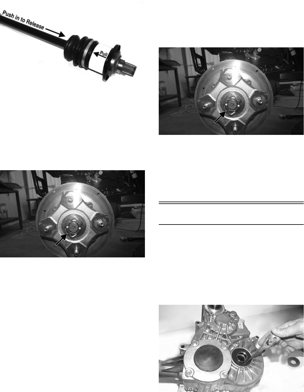
121
PR729C
NOTE: To ensure proper axle seating, give the axle
a light pull; the axle should remain “clipped” in place.
2. Install the axle into the knuckle; then swing the
knuckle upward and engage the ball joint of the upper
A-arm into the knuckle; using a new “patch lock” cap
screw secure and tighten to 35 ft-lb.
3. Install the hub assembly and secure with the hub nut.
Tighten the nut to 200 ft-lb and install a new cotter
pin. Spread the pin to secure the nut.
WT328A
4. Using new “patch lock” cap screws, secure the brake
caliper to the brake disc. Tighten to 20 ft-lb.
5. Install the wheels and tighten in 20 ft-lb increments to
40 ft-lb (steel wheel) or 80 ft-lb (aluminum wheel).
6. Remove the vehicle from the stand.
INSTALLING FRONT DRIVE AXLE
1. Push the axle shaft into the CV coupler to release the
lock ring; then position the drive axle in the gear case
and steering knuckle; then insert the ball joints into
the steering knuckles. Secure with cap screws tight-
ened to 35 ft-lb.
2. Secure the lower shock eyelet to the upper A-arm
with a new “patch-lock” cap screw and existing
washer. Tighten to 35 ft-lb.
3. Slide the hub w/brake disc into position in the steer-
ing knuckle followed by an axle nut. Finger-tighten
at this time.
4. Install the brake caliper on the steering knuckle using
new “patch-lock” cap screws. Tighten to 20 ft-lb.
5. Set the parking brake; then turn the ignition switch to
the ON position, select LOCK on the drive select
switch. Turn the ignition switch to the OFF position.
6. Tighten the axle nut (from step 3) to 200 ft-lb; then
install and spread a new cotter pin making sure each
side of the pin is flush to the hub nut.
WT328A
7. Install the wheel and tighten in a crisscross pattern in
20 ft-lb increments to 80 ft-lb (aluminum wheel) or
to 40 ft-lb (steel wheel).
8. Remove the vehicle from the support stand.
9. Check the front differential lubricant level and add
lubricant as necessary (see Periodic Maintenance/
Tune-Up).
Transaxle
REPLACING SEALS
Output (Axle) Seals
NOTE: The transaxle does not need to be removed
for this procedure.
1. Support the vehicle on an appropriate stand; then
remove a rear wheel and axle.
2. Using an awl and a mallet, pry the seal from the case
taking care not to damage the seal bore.
TA118
3. Wipe any oil or dirt from the seal area of the transaxle.
4. Using an appropriate seal installer and protector,
install a new seal so it seats fully past the chamfer of
the case (approximately 1.5-2.0 mm deep).
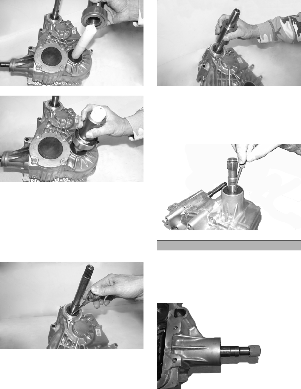
122
TA113
TA115
Input (Driven Clutch) Seal
NOTE: The transaxle does not need to be removed
for this procedure.
1. Support the vehicle on an appropriate stand; then
remove the left rear wheel, the outer clutch cover, the
clutches, and the inner clutch cover.
2. Using an awl and a mallet, pry the seal from the case
taking care not to damage the seal bore.
TA109
3. Wipe any oil or dirt from the seal area of the transaxle.
4. Using an appropriate seal installer and protector,
install a new seal so it seats flush with the case (0.5
mm deep).
TA110
Front Output Seal
NOTE: The transaxle must be removed for this pro-
cedure.
1. Using an awl and a mallet, pry the seal from the case
taking care not to damage the seal bore.
TA117
2. Wipe any oil or dirt from the seal area of the transaxle.
3. Tape the splined portion of the pinion shaft to protect
the seal; then using an appropriate seal installer, install
the front output seal (approximately 0.5-1.0 mm
deep).
TA129
CAUTION
Do not drive the awl too far or bearing damage will occur.
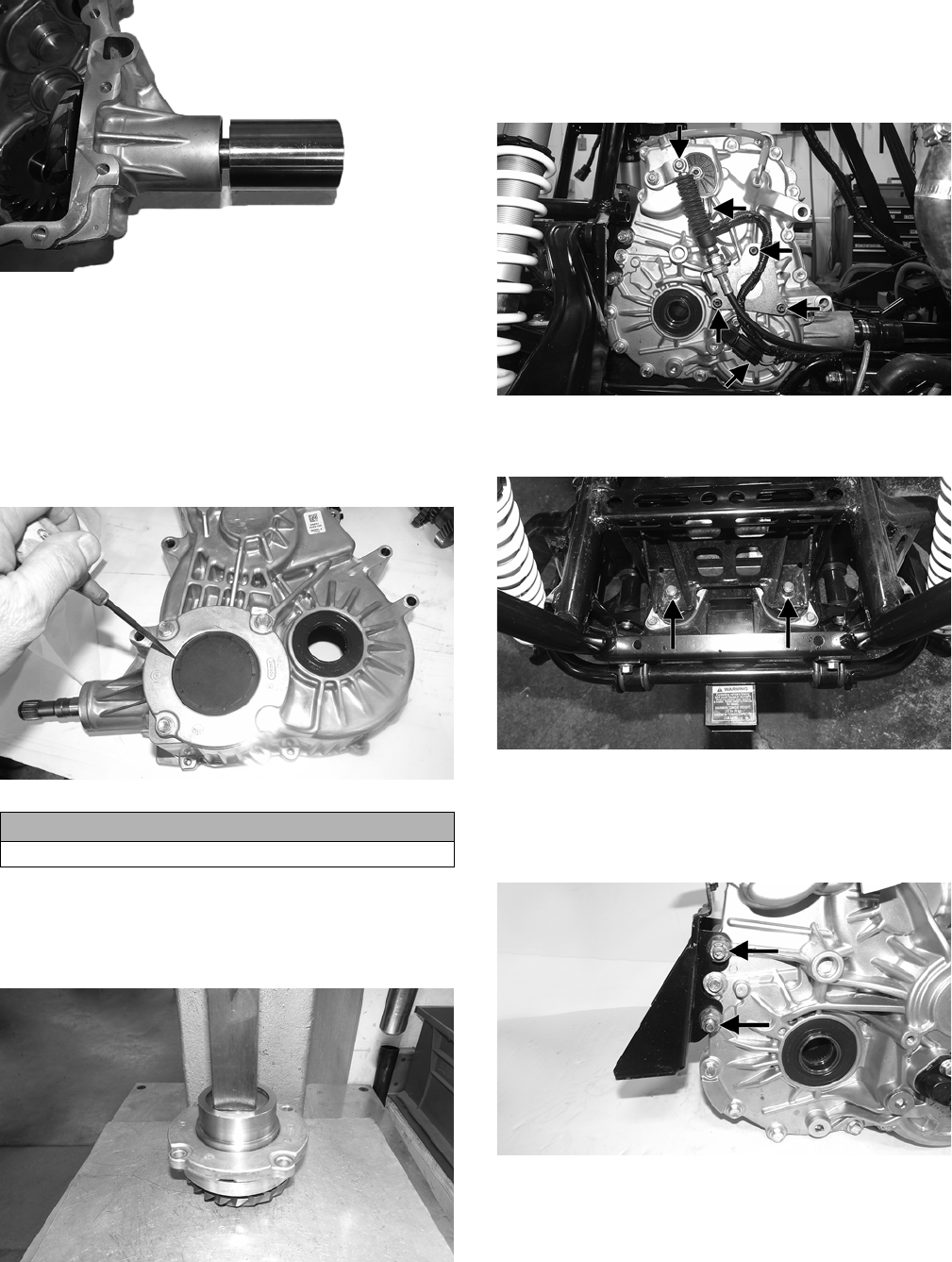
123
TA130
Pinion Plug
NOTE: The transaxle does not need to be removed
for this procedure.
1. Support the vehicle on an appropriate stand; then
remove the right rear wheel and axle.
2. Using an awl and a mallet, pry the pinion plug from
the case taking care not to damage the seal bore.
TA084
3. Wipe any oil or dirt from the plug area of the transaxle.
4. Using an appropriate tool, lightly tap the plug so it
seats fully past the chamfer of the case (approximately
1.0-1.5 mm deep).
TA132
REMOVING
1. Place the vehicle securely on a support stand.
2. Remove the hood, wheels, seats, center console, floor,
and driveshaft.
3. Remove the E-clip connecting the shift cable to the
transaxle. Remove the shift cable bracket; then dis-
connect the speed sensor and the gear position switch.
WT439A
4. Remove and discard the two lock nuts securing the
transaxle to the frame.
WT440A
5. Lift the transaxle off the mounting studs and remove
out the left side of the vehicle.
6. Remove the bracket securing the transaxle to the rear
mounts. Discard the lock nuts.
WT435A
SEPARATING HALVES
1. With the transaxle on a bench, drain the fluid into a
suitable pan.
CAUTION
Do not drive the awl too far or bearing damage will occur.
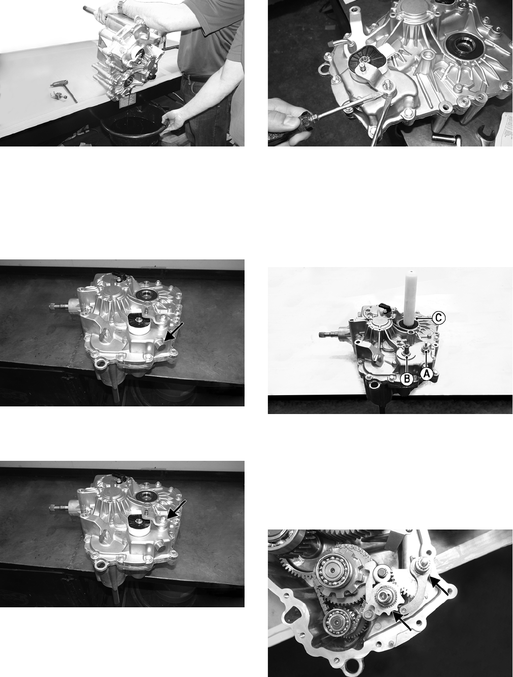
124
TA004
NOTE: Tip the transaxle towards the drain to get
any remaining fluid.
NOTE: Install the drain plug and tighten to 18 ft-lb.
2. Lay the transaxle flat on the bench; then remove the
19 mm detent (gold plug) near the gear position
switch. Account for the spring and O-ring.
TA012A
3. Remove and discard the lock nut securing the bell
crank; then using two screwdrivers, pry the bell crank
off the shift shaft.
TA012B
TA027
4. Remove the clip securing the gear position switch.
Gently pry the switch off the shift rail and account for
the wave washer.
5. Remove the screws securing the case halves together.
6. While prying the two halves apart with an assistant,
use a rubber mallet to gently tap the shift shaft (A),
shift drum (B), and output shaft (C) into the lower
half.
TA131A
NOTE: Use a suitable bearing seal protection tool
and when driving the bearing and gears into the
lower half of the transaxle.
7. Clean any silicone residue from the case halves.
DISASSEMBLING HALVES
1. Remove the shift shaft assembly and the detent.
TA006A
2. Remove the park pawl with dowel pin and account for
the spring.
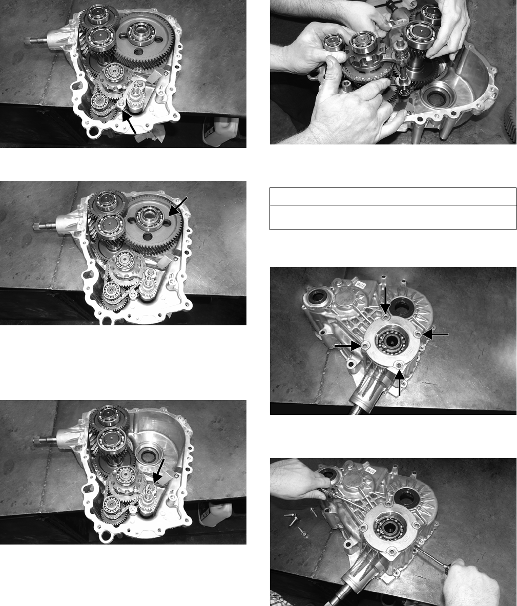
125
TA028A
3. Remove the output gear assembly with bearings.
TA026
4. Lift on the shift rail assembly to disengage the rail assem-
bly from the case and rotate the rail away from the shift
drum; then remove the shift drum assembly.
NOTE: Spread the shift forks while removing.
TA022A
5. Using an assistant, lift and remove all remaining shafts
simultaneously.
TA059
6. Place the transaxle upright on the bench and dump any
remaining fluid into the pan.
7. With the transaxle flat on the bench, remove the four
screws securing the pinion gear assembly.
TA025A
8. Pry the pinion gear assembly to remove it from the
case. Account for the shim.
TA029
9. If the pinion shaft or bearing are being removed, use
an awl and mallet to pry the front output seal off the
case.
AT THIS POINT
If the pinion shaft and gear are not being serviced or
replaced, no further disassembling is required.
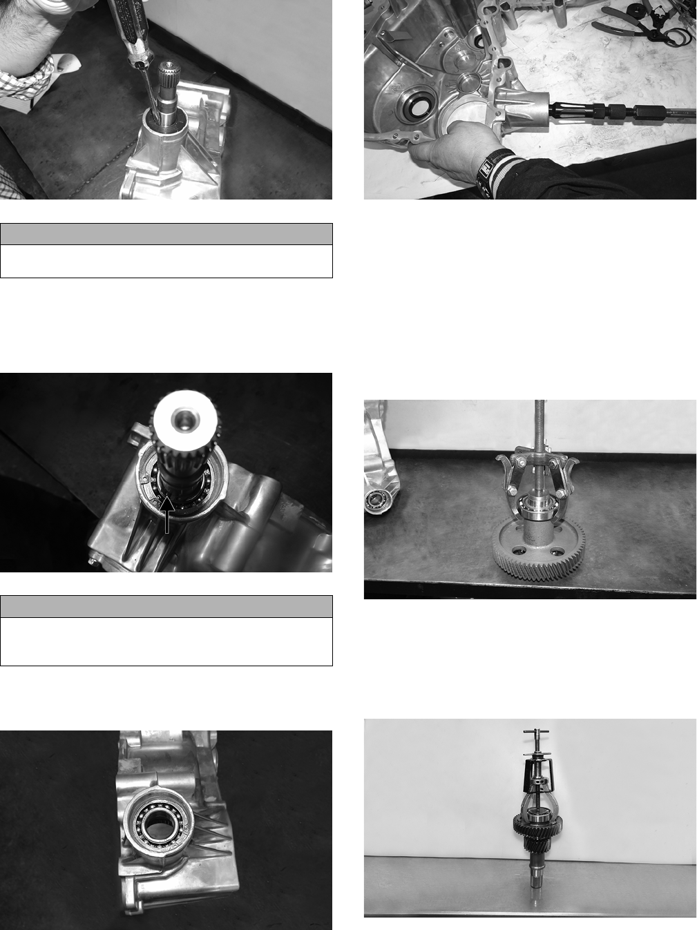
126
TA009
NOTE: The pinion seal must be replaced if removed.
10. Remove the inner snap ring on the front output shaft;
then using a mallet, tap the front output shaft down
into the case half. Account for the shim.
TA073A
11. Remove the outer snap ring and shim securing the ball
bearing; then using an appropriate tool, remove the
bearing.
TA013
TA127
SERVICING COMPONENTS
NOTE: If any bearing is removed, install a new bear-
ing using a suitable press.
NOTE: Keep all components in order for assembling
purposes.
A. Output Gear
1. Inspect the bearings for free and smooth turning. If
either bearing does not turn freely, it must be replaced.
TA016
2. Inspect the gear teeth for nicks, cracks, chips, or signs
of wear. If any are present, the gear must be replaced.
B. Intermediate Shaft
1. Inspect the bearing for free and smooth turning. If the
bearing does not turn freely, it must be replaced.
TA035
2. Inspect the gear teeth for nicks, cracks, chips, or signs
of wear. If any are present, the gear must be replaced.
CAUTION
There is a ball bearing below the pinion seal. Use cau-
tion not to damage the bearing while removing the seal.
CAUTION
When tapping the output shaft, make sure not to drop
the shaft when it releases from the bearing to avoid gear
damage.
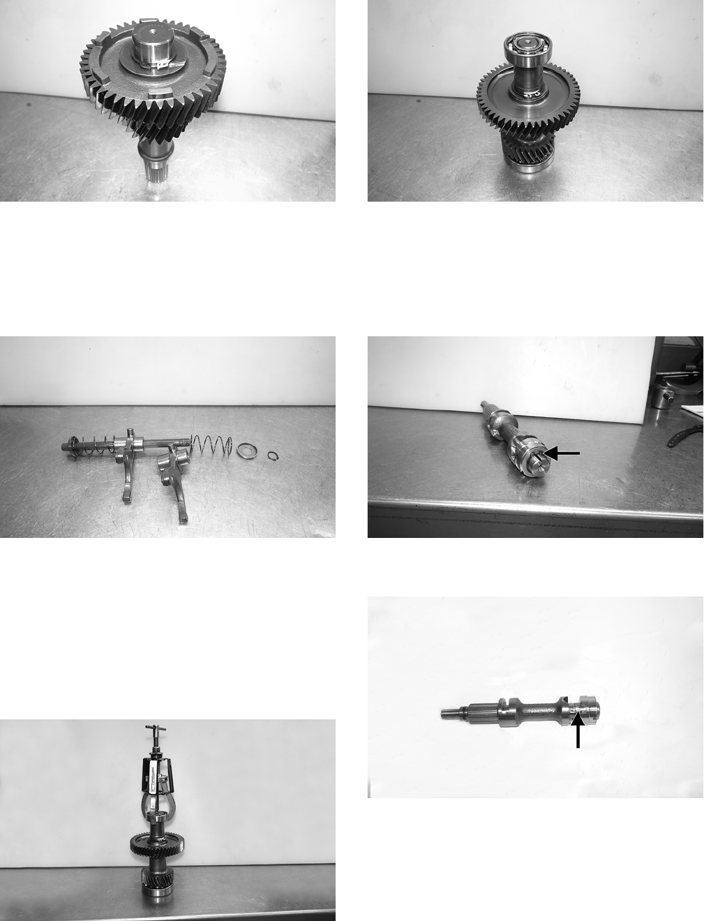
127
TA036
3. Inspect the shaft gear teeth for nicks, cracks, chips, or
signs of wear. If any are present, the shaft must be
replaced.
C. Shift Shaft Rail
1. Inspect the shift forks for nicks, cracks, chips, or signs
of wear. If any are present, the forks must be replaced.
TA041
2. Inspect the rail for nicks, cracks, chips, or signs of
wear. If any are present, the rail must be replaced.
D. Shift Shaft
Inspect the gear for nicks, cracks, chips, or signs of wear.
If any are present, the gear must be replaced.
E. Idler Shaft
1. Inspect the bearings for free and smooth turning. If
either bearing does not turn freely, it must be replaced.
TA033
2. Inspect the gear teeth for nicks, cracks, chips, or signs
of wear. If any are present, the gear must be replaced.
TA034
3. Inspect the shaft gear teeth for nicks, cracks, chips, or
signs of wear. If any are present, the shaft must be
replaced.
F. Shift Drum
1. Remove the snap ring and washer; then pull the cam
off the shift drum.
TA038A
2. Inspect the cam groove for signs of wear. If present,
replace the cam.
TA133A
3. Check the shaft splines for nicks, cracks, chips, or
signs of wear. If any are present, the shift drum must
be replaced.
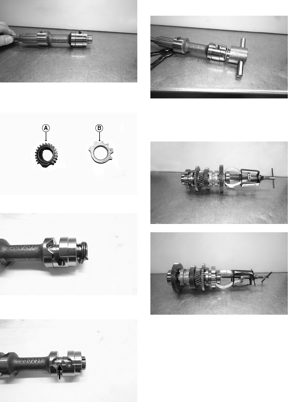
128
TA039
4. Check the detent star (A) and shift drum gear (B) for
nicks, cracks, chips, or signs of wear. If any are pres-
ent, the detent star must be replaced.
TA057A
5. Install the spring into the shift drum.
TA121
6. Rotate the cam clockwise so the tab of the spring installs into
the shift drum groove. Install the washer to retain the spring.
TA122A
7. While holding pressure on the washer, rotate the cam
counterclockwise to lock the cam onto the shift drum.
TA040
8. Install the snap ring.
G. Reverse Shaft
1. Inspect the bearings for free and smooth turning. If
either bearing does not turn freely, it must be replaced.
TA048
TA055
2. Inspect the gear teeth for nicks, cracks, chips, or signs
of wear. If any are present, the gear must be replaced.
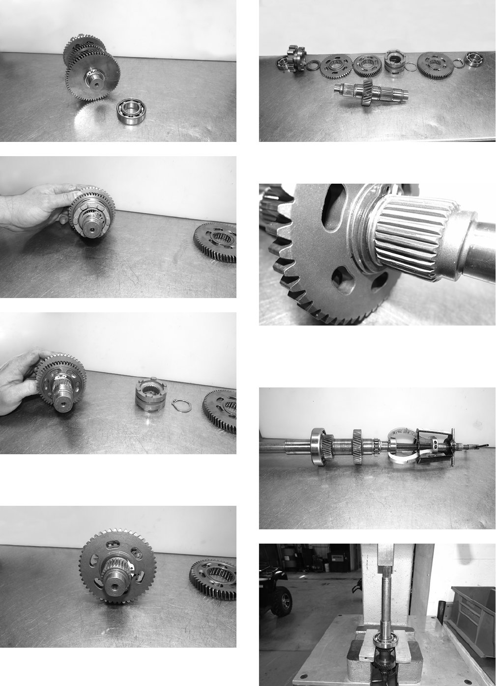
129
TA049
TA050
TA051
3. Inspect the shaft gear teeth for nicks, cracks, chips, or
signs of wear. If any are present, the shaft must be
replaced.
TA052
TA053
4. Inspect the dogs for nicks, cracks, chips, or signs of
wear. If any are present, the dog must be replaced.
TA054
H. Input Shaft
1. Inspect the bearings for free and smooth turning. If
either bearing does not turn freely, it must be replaced.
TA042
TA044
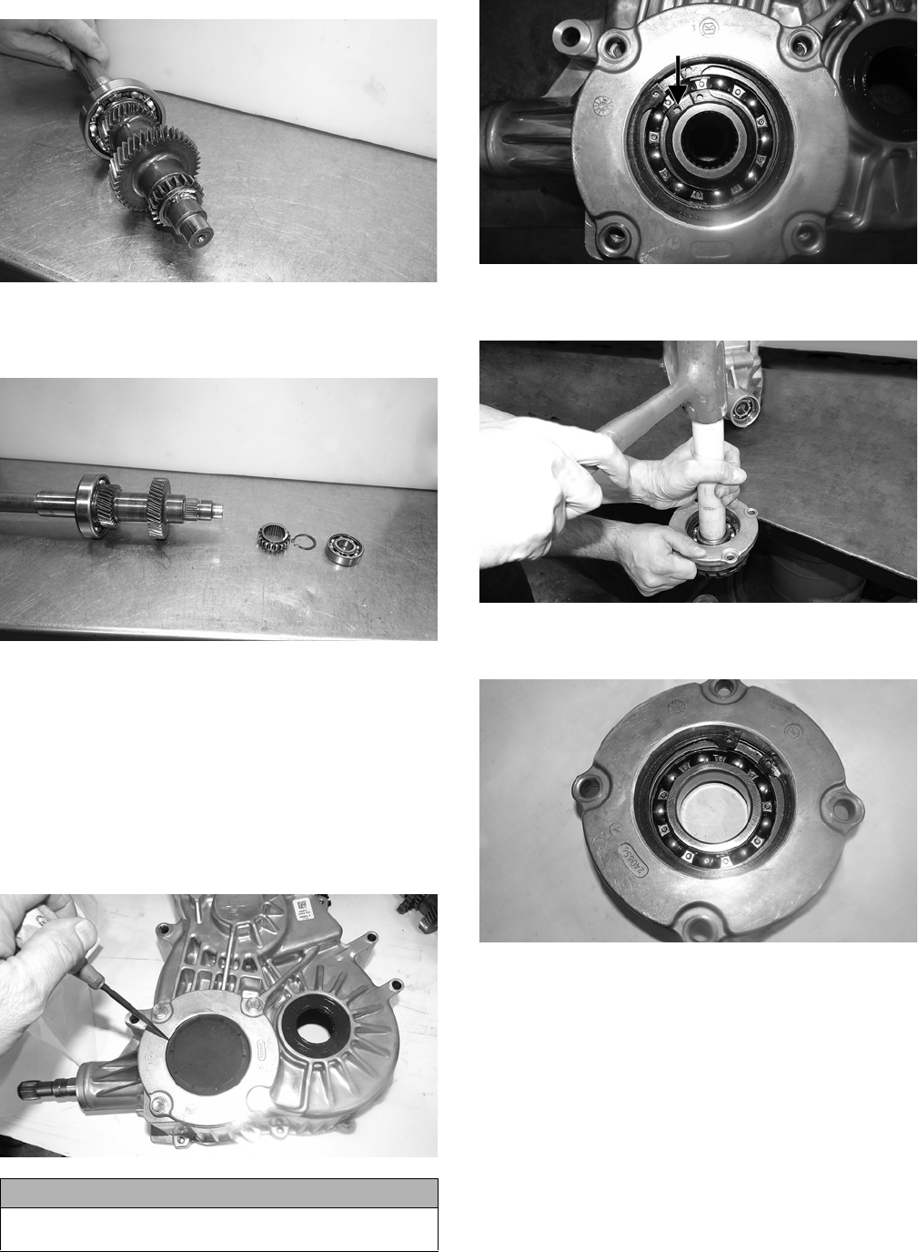
130
2. Inspect the sprocket teeth for nicks, cracks, chips, or
signs of wear. If any are present, the sprocket must be
replaced.
TA043
3. Inspect the shaft gear teeth for nicks, cracks, chips, or
signs of wear. If any are present, the shaft must be
replaced.
TA045
K. Pinion Assembly
Inspect the teeth of the pinion gear and front output shaft.
If any chipping, nicks, wear, or damage are observed, the
pinion assembly must be replaced.
Turn the pinion gear by hand. If any sticking or binding is
observed, the bearing must be replaced. Use the following
procedure:
1. Using an awl, pry the plug from the case. Discard the
plug.
TA084
2. Remove the small inner snap ring and account for the
shim.
TA082A
3. With the aid of an assistant and using an appropriate
driver, remove the gear.
TA031
4. Remove the large outer snap ring and account for the
shim.
TA086
5. Using an appropriate bearing driver, press the bearing
from the housing.
CAUTION
Do not drive the awl too far or bearing damage will
occur.
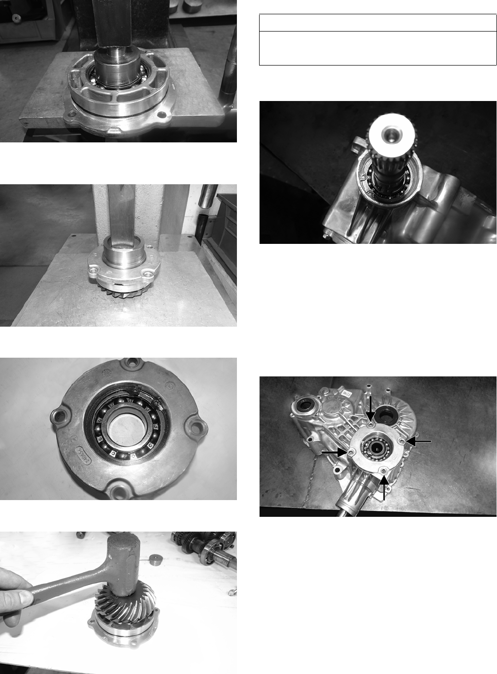
131
TA081
6. Using an appropriate bearing installer, install a new
bearing into the housing.
TA132
7. Install the large outer snap ring with the shim.
TA086
8. Install the gear into the housing.
TA077
9. Install the small inner snap ring with shim.
BACKLASH
1. Install the pinion shaft into the case. With the appro-
priate shim in place, secure with the snap ring.
TA073
NOTE: To determine the appropriate shim, start with
the thickest shim and install the snap ring. If the snap
ring will not fit in the groove, remove the shim and
install the next size smaller shim. Continue until the
snap ring can be installed.
2. With the appropriate shim in place and the O-ring
coated with molybdenum grease, install the pinion
gear assembly into the case half and secure with the
four screws. Tighten to 20 ft-lb.
TA025A
NOTE: To determine the appropriate shim, proceed to
step 3.
3. Using an appropriate tool, lock the pinion gear in place.
AT THIS POINT
If the pinion shaft or gear were replaced or serviced,
backlash must be checked. If not, proceed to ASSEM-
BLING HALVES.
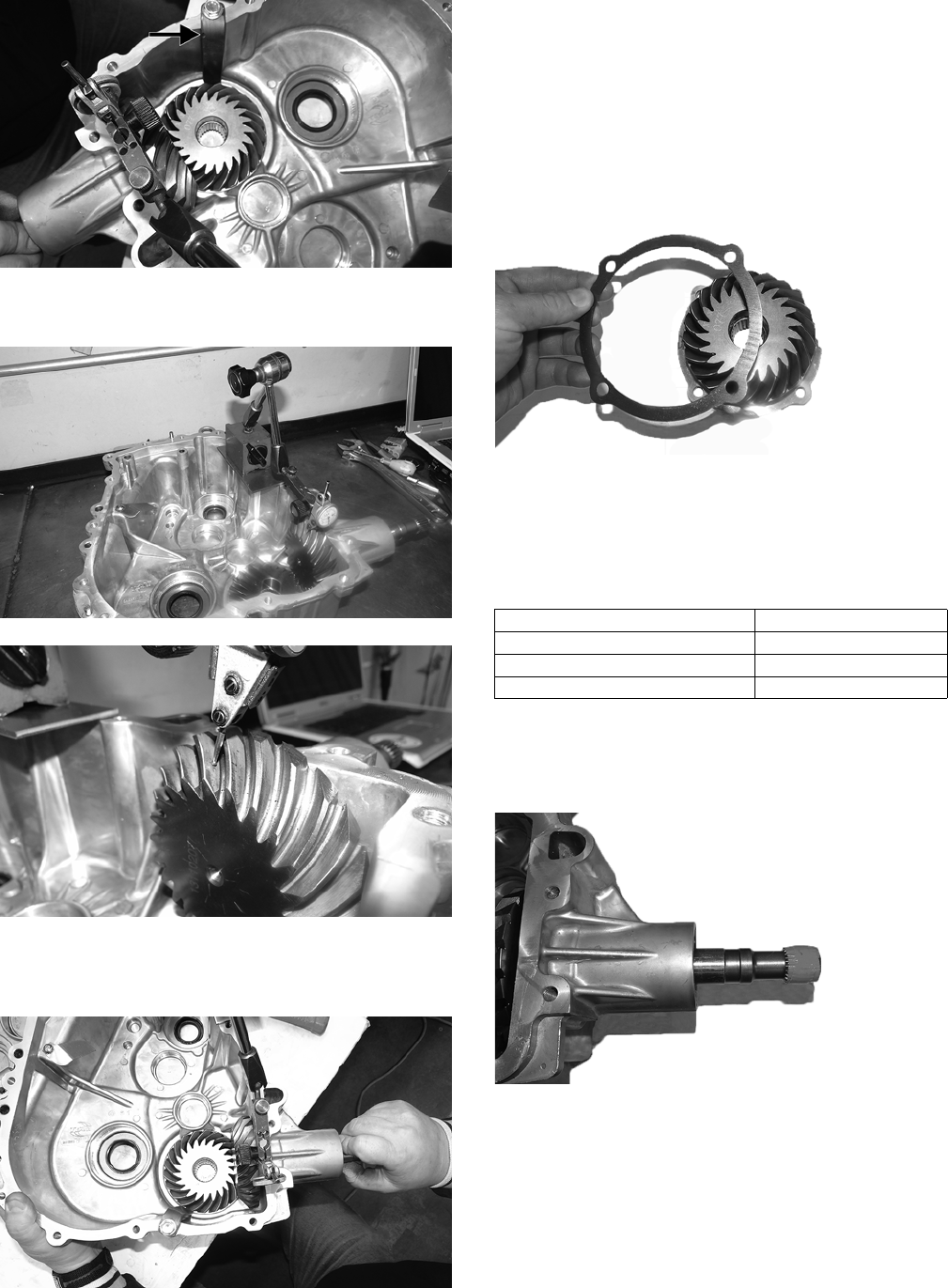
132
TA124A
4. Mount a dial indicator so the tip is contacting a tooth
on the pinion shaft.
TA096
TA095
5. While pushing in on the front output shaft, and while
rocking the shaft back and forth and note the maxi-
mum backlash reading on the gauge.
TA125
6. Acceptable backlash range is 0.076-0.241 mm (0.003-
0.0095 in.).
NOTE: If backlash measurement is within the
acceptable range, no correction is necessary.
7. If backlash measurement is less than specified,
remove the existing shim and install a new thicker
shim (from shim kit).
TA102
8. If backlash measurement is more than specified,
remove the existing shim and install a thinner shim.
NOTE: Continue to remove, measure, and install
until backlash measurement is within tolerance. Note
the following chart.
9. Tape the splined portion of the pinion shaft to protect
the seal; then using an appropriate seal installer, install
the front output seal so it seats fully past the chamfer
of the case.
TA129
Backlash Measurement Shim Correction
Under 0.076 mm (0.003 in.) Increase Shim Thickness
At 0.076-0.241 mm (0.003-0.0095 in.) No Correction Required
Over 0.241 mm (0.0095 in.) Decrease Shim Thickness
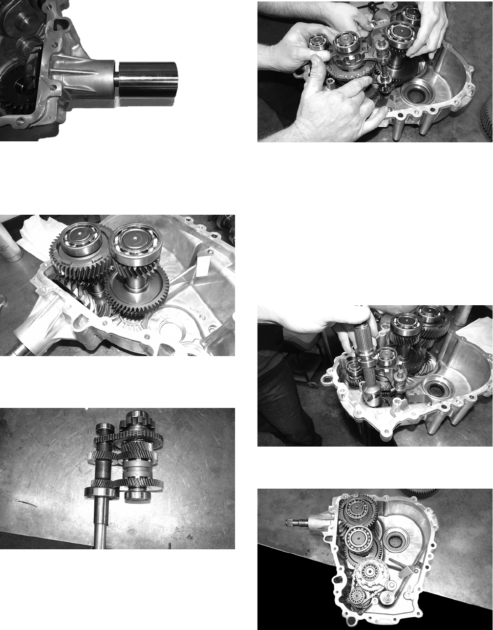
133
TA130
ASSEMBLING HALVES
1. Install the intermediate shaft and idler shaft into the
case only partially. Do not seat the shafts completely
into the case at this time.
TA056
2. With the aid of an assistant and with the gear forks in
position, install the input shaft and reverse shaft with
chain as an assembly.
TA058
TA059
NOTE: Make sure the shift fork pins face the installer.
NOTE: Engage all four shafts before seating them
simultaneously into the case.
NOTE: Ensure the chain stays engaged in the
sprocket teeth.
NOTE: The shift shaft rail should remain un-seated at
this point.
3. Install the shift drum into the case; then engage the
fork tabs into the grooves in the shift drum.
TA062
4. Pinch the forks together and slide the rail into position
in the case.
TA063
5. Install the output gear. Use slight force to seat it and
ensure the gear teeth engage with the intermediate
shaft.
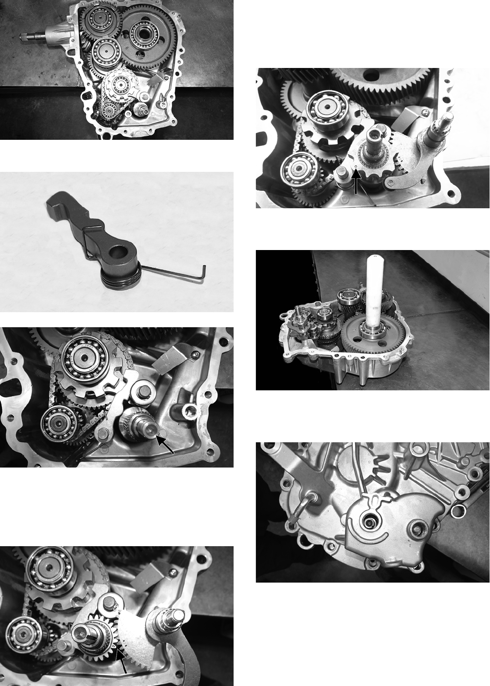
134
TA064
6. Install the park pawl with dowel and spring.
TA074
TA065A
7. Install the shift drum gear onto the shift drum aligning
the appropriate splines of the drum with the gear.
8. Install the shift shaft gear onto the shift shaft with the
timing marks facing up; then install into the case with
the gear aligning with the shift drum gear.
TA066A
NOTE: Rotate the shift drum and the shift shaft to
ensure the timing marks are correctly aligned.
9. Install the star detent over the shift drum aligning the
appropriate splines of the detent with the shaft splines
and the dot facing up.
TA134A
10. Install an appropriate bearing seal protector tool onto
the bearing of the output shaft.
TA067
11. Apply a coat of Loctite #5699 to the case; then ensur-
ing the shift shaft (O-ring lightly coated with grease)
and shift rail are correctly seated, install the cover.
TA068
NOTE: It will be necessary to tap the cover onto the
case using a rubber mallet. Ensure the alignment
pins are properly oriented.
12. Secure the cover with the cap screws and tighten to 20
ft-lb.
13. Install the detent (gold plug) with spring and O-ring.
Tighten to 20 ft-lb.
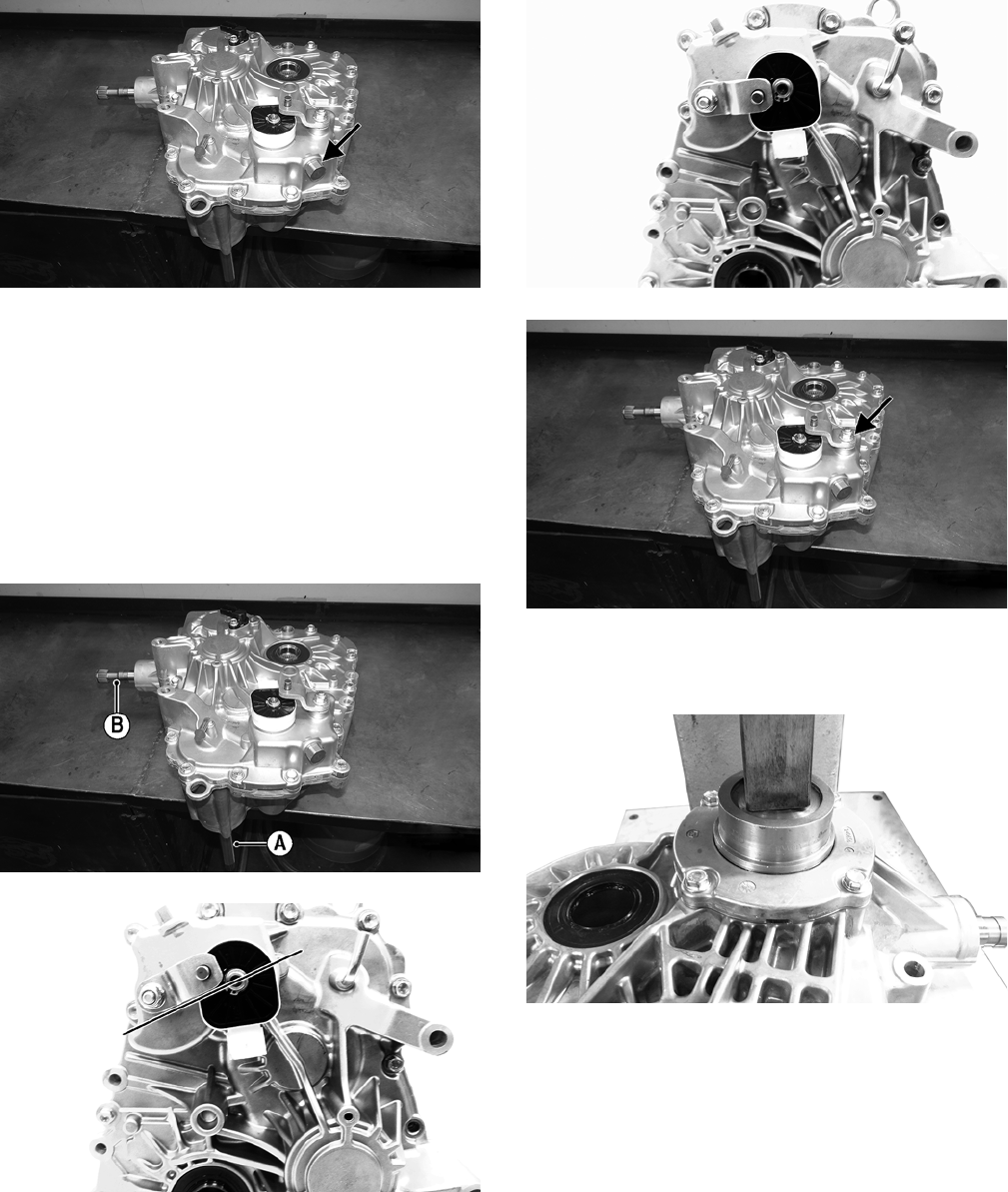
135
TA012A
14. Install the gear position switch. Secure with the wave
washer and snap ring.
15. Install the bell crank being sure to correctly align the
splines of the bell crank and shift shaft and secure
with a new lock nut. Tighten to 15 ft-lb.
NOTE: Ensure the transaxle is in neutral by turning
the input shaft (A). It should turn freely and the front
output shaft (B) should not turn. If the front output
shaft turns with the input shaft, turn the bell crank to
the correct position.
TA012C
TA138A
TA137A
TA012B
16. Using an appropriate seal installer, gently install a new
plug over the pinion gear assembly so it fully seats
past the chamfer (approximately 1.0-1.5 mm deep).
TA135A
17. Add the appropriate amount of Arctic Cat Synthetic
Transaxle Fluid to the transaxle; then install the fill
plug and tighten to 18 ft-lb.
INSTALLING
1. Using new lock nuts, secure the bracket to the rear of
the transaxle. Tighten to 38 ft-lb.
2. Place the transaxle into position on the rear mounting
studs and secure using new lock nuts. Tighten to 25 ft-lb.
CORRECT
INCORRECT
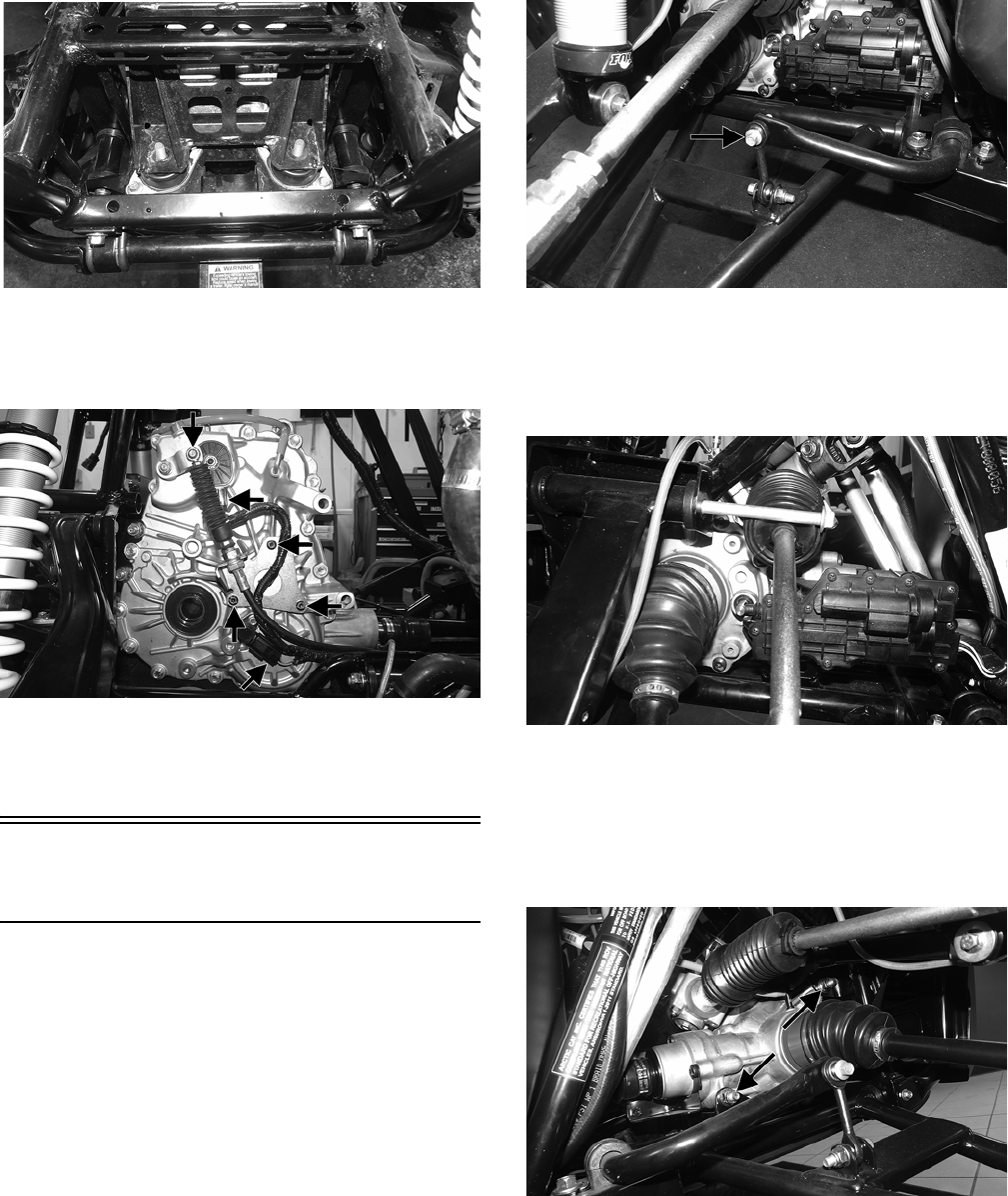
136
WT430
3. Install the shift cable bracket and tighten to 7 ft-lb.
4. Connect the shift cable to the transaxle and secure with the
E-clip. Connect the speed sensor and gear position switch.
WT439A
5. Install the hood, wheels, seats, center console, floor,
and driveshaft.
6. Remove from the vehicle from the support stand.
Driveshaft/Carrier
Bearing
REMOVING
1. Remove the hood, seats, center console, floor, and engine.
2. Secure the vehicle on a support stand to elevate the
wheels; then remove the front wheels.
3. Remove the lower cap screw on the front left shock
and slide the shock off of the upper A-arm. Discard
the cap screw but retain the washer.
WT323A
4. Rotate the steering rack all the way to the right; then
remove the upper cap screw securing the upper A-arm
to the frame and remove it from the mounting brack-
ets. Account for the washer and bushing. Discard the
lock nut.
WT334
NOTE: Removing the inner upper A-arm from the
frame will aid in removing the upper front differential
cap screw.
5. Remove the cap screws securing the front differential to
the frame. Account for washers and discard the lock nuts.
WT423A
6. Remove the cap screws and lock nuts securing the carrier
bearing housing to the frame. Discard the lock nuts.
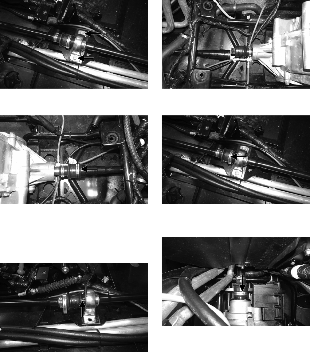
137
WT421A
7. Remove the front boot clamp securing the driveshaft
to the transaxle.
WT424A
NOTE: Having the transmission in neutral will aid in
rotating the driveshaft for ease of removing the clamps.
NOTE: Using a suitable tool to break the seal of the
boot from the driveshaft will aid in removing the
driveshaft.
WT437A
8. From the front of the vehicle, hold both of the axles
and pull forward until the front differential is against
the frame. Slide the driveshaft off of the transaxle.
WT426
9. Remove the clamp behind the carrier bearing and slide the
rear driveshaft rearward. Remove the rear driveshaft.
WT421B
10. Remove the front boot clamp securing the front differ-
ential to the driveshaft. Slide the front driveshaft rear-
ward and remove it from the vehicle.
WT422A
NOTE: At this point, no further disassembling is
required to replace the driveshaft. If the technician’s
objective is to replace the carrier bearing, proceed to
step 11.
NOTE: The carrier bearing is a non serviceable
item. It must be replaced as an assembly.
11. Loosen the set screws on the bearing but do not
remove them.
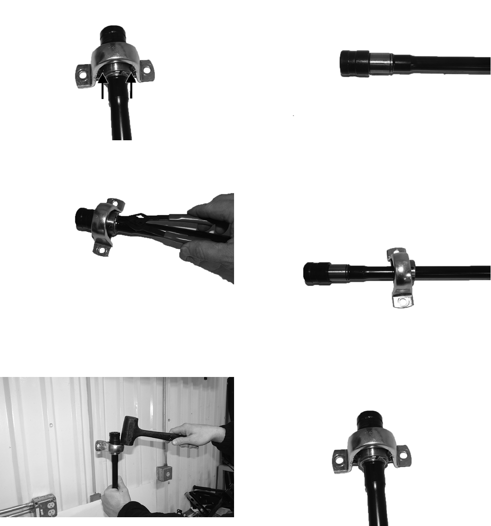
138
WT431A
12. Remove the snap ring.
WT434
13. Slide the carrier bearing assembly off of the shaft.
NOTE: It may be necessary to lightly tap the carrier
bearing with a mallet to aid in removing it.
WT436
INSTALLING
NOTE: If the carrier bearing was not removed, pro-
ceed to step 5.
NOTE: The carrier bearing is intended to be a “slip
fit” assembly. It is very important that the surface is
free of nicks and rust. It may be necessary to lightly
scrub unpainted surfaces with emery cloth to ensure
a smooth surface.
WT438
1. Slide the carrier bearing onto the shaft with the set
screws facing down towards the longer end of the
driveshaft making sure it is past the snap ring groove.
Do not tighten the set screws at this time.
WT432
2. Slide the snap ring over the shaft and snap them into
position.
WT431
3. Remove each set screw and place one drop of red Loc-
tite #271 on each; then tighten to 75 in.-lb.
4. With the front differential slid forward against the
frame, apply a small amount of molybdenum grease to
the splines and install the front driveshaft into the
front differential. Tighten the clamp securely.
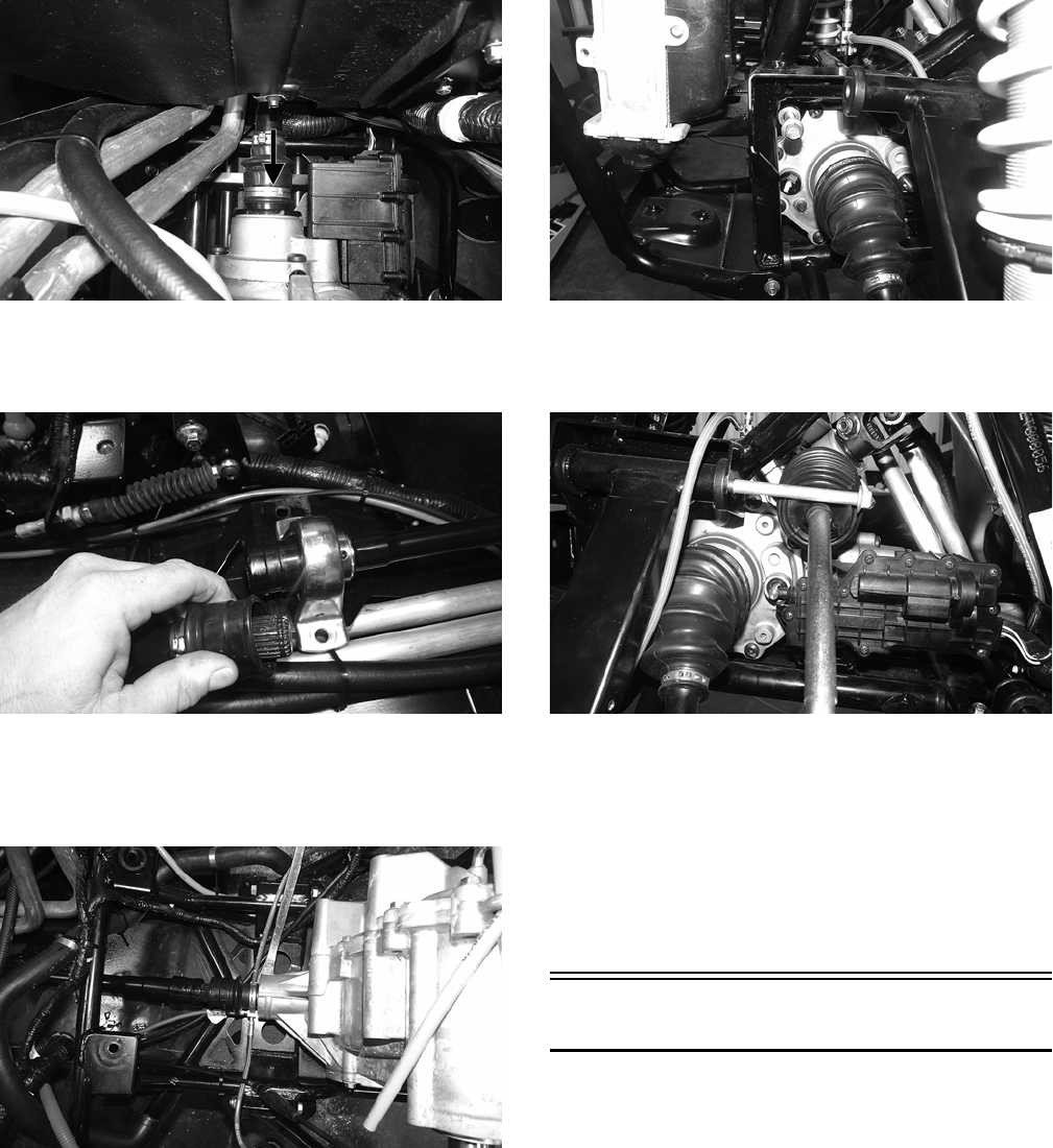
139
WT422A
5. Apply molybdenum grease to the splines on both ends of
the rear driveshaft and insert the rear driveshaft into the
mating end of front driveshaft. Tighten the clamp securely.
WT427
6. Mate the rear driveshaft with the output shaft of the trans-
axle so they are meshed together by pushing on the front
axles rearward until the front differential mounting holes
are aligned. Tighten the clamp securely.
WT429
7. Using new lock nuts, secure the carrier bearing hous-
ing to the frame. Tighten to 35 ft-lb.
8. Install the front differential cap screws, washers, and
new lock nuts. Tighten to 38 ft-lb.
WT425
9. With the steering rack turned all the way to the right,
install the front left upper A-arm cap screw, washer,
and new lock nut. Tighten to 35 ft-lb.
WT334
10. Install the front left shock onto the upper A-arm. With
the existing washer and new patch lock cap screw,
tighten to 25 ft-lb.
11. Install the front wheels. Tighten in 20 ft-lb increments
to 40 ft-lb (steel wheel) or 80 ft-lb (aluminum wheel).
12. Install the hood, seats, center console, floor, and
engine.
13. Remove the vehicle from the stand.
Hub
REMOVING
1. Secure the vehicle on a support stand to elevate the
wheel; then remove the wheel.
2. Remove the hub nut securing the hub and discard the
cotter pin.
3. Remove the brake caliper.
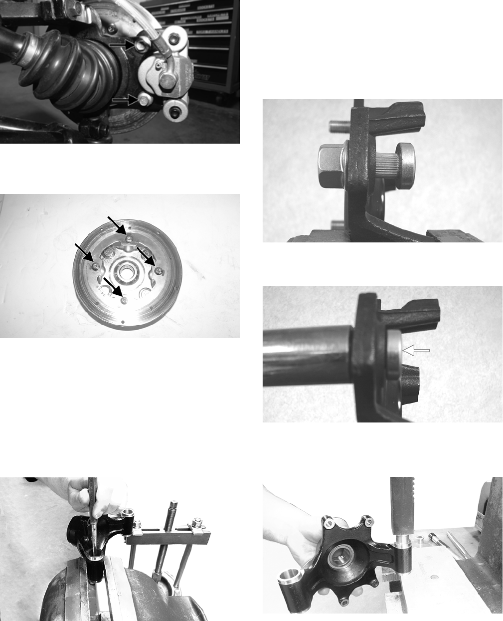
140
WT287A
4. Remove the hub assembly.
5. Remove the four cap screws securing the brake disc.
WT325A
NOTE: It may be necessary to heat the cap screws
to loosen the Loctite.
6. Remove the seals and sleeve and inspect for cracks,
nicks, or tears.
NOTE: Only remove the bushings if they must be
serviced.
7. Place the hub in a bench vise and using an appropriate
tool, drive out and discard the bushings.
WT597
CLEANING AND INSPECTING
1. Clean all hub components.
2. Inspect all threads for stripping or damage.
3. Inspect the brake disc (if applicable) for cracks or warping.
4. Inspect the hub for pits, cracks, loose studs, or spline wear.
REPLACING WHEEL STUDS
1. Secure the hub in a suitable holding fixture and
remove the brake disc (if applicable).
2. Drive the damaged stud out of the hub; then place the
new stud into the hub and thread on an appropriate
flange nut.
PR250
3. Using a socket and ratchet handle, tighten the nut until
the stud is fully drawn into the hub.
PR252A
INSTALLING
1. Using a suitable press, press in the new bushing.
WT598
2. Place the hub in a bench vise and using a 16 mm
reamer, ream out the bushings.
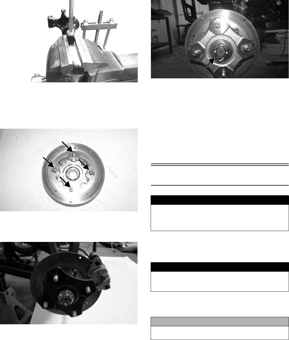
141
WT595
3. Insert the sleeve into the hub and apply molybdenum
grease to the inside of the seals. Install the seals on the
hub.
4. Secure the brake disc to the hub with four new “patch
lock” cap screws. Tighten to 15 ft-lb.
WT325A
5. Install the hub assembly onto the axle. Install the
brake caliper and secure with new “patch-lock” cap
screws. Tighten to 20 ft-lb.
WC281
6. Install the hub nut and tighten to 200 ft-lb. Install a
new cotter pin and spread the pin to secure.
WT328A
NOTE: During assembly, new cotter pins should
always be used.
NOTE: If the cotter pin cannot be inserted due to
misalignment of the hole and the slots in the nut,
always tighten the nut until it is properly aligned.
7. Install the wheel and using a crisscross pattern, tighten the
wheel nuts in 20 ft-lb increments to a final torque factor of
40 ft-lb (aluminum wheel) or 80 ft-lb (steel wheel).
8. Remove the vehicle from the support stand.
Hydraulic Brake Caliper
REMOVING/DISASSEMBLING
1. Secure the vehicle on a support stand to elevate the
wheel; then remove the wheel.
2. Drain the brake fluid from the caliper, hose, and mas-
ter cylinder through the bleed screw by pumping the
brake pedal.
NOTE: Whenever brake components are removed,
disassembled, or repaired where brake fluid is
exposed to air, drain all fluid and replace with new
DOT 4 brake fluid from an unopened container. Brake
fluid readily absorbs moisture from the air signifi-
cantly lowering the boiling point. This increases the
chance of vapor lock reducing braking power and
increasing stopping distance.
! WARNING
Arctic Cat recommends only authorized Arctic Cat Wild-
cat dealers perform hydraulic brake service. Failure to
properly repair brake systems can result in loss of con-
trol causing severe injury or death.
! WARNING
Never let brake fluid contact the eyes. Damage to the eyes
will occur. Always wear appropriate protective safety gog-
gles and latex gloves when handling brake fluid.
CAUTION
Brake fluid is highly corrosive. Do not spill brake fluid on
any surface of the vehicle and do not reuse brake fluid.
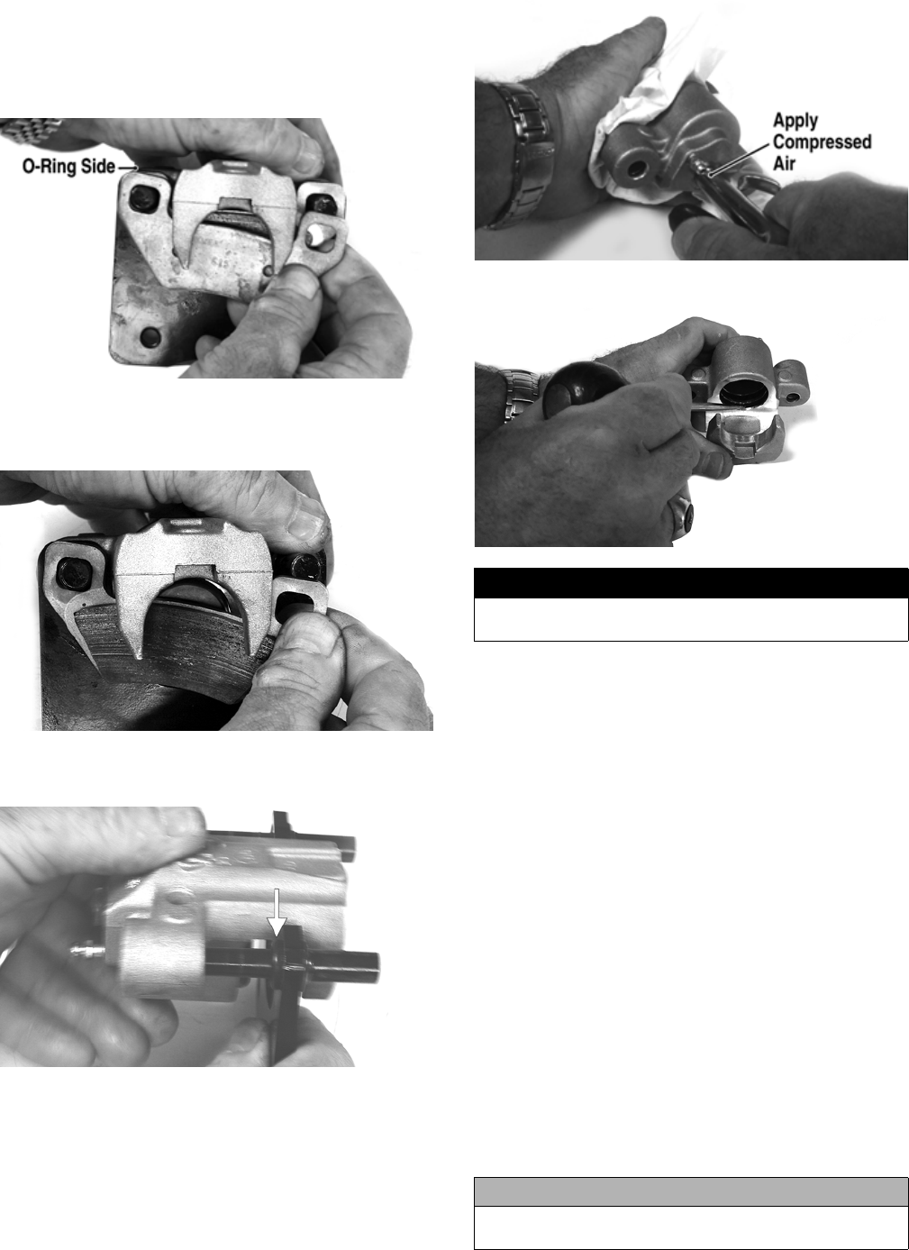
142
3. Remove the brake hose from the caliper and close the
bleed screw; then remove the caliper.
4. Compress the caliper holder against the caliper (oppo-
site the O-ring side) and remove the outer brake pad;
then remove the inner brake pad.
PR237A
NOTE: If brake pads are to be returned to service,
do not allow brake fluid to contaminate them.
PR238
5. Remove the caliper holder from the caliper and dis-
card the O-ring.
PR239B
NOTE: The O-ring is used for shipping purposes
and provides no function in operation.
6. Cover the piston end of the housing with a shop towel;
then keeping fingers clear of piston travel, apply com-
pressed air to the fluid port to blow the piston free of
the housing. Account for two seal rings in the housing.
PR713A
PR715
7. Using an appropriate seal removal tool, carefully
remove the seals from the brake caliper housing; then
remove four O-rings from the brake caliper housing
noting the location of the different sized O-rings. Dis-
card all seals, O-rings, and crush washers.
CLEANING AND INSPECTING
1. Clean all caliper components (except the brake pads)
with DOT 4 brake fluid. Do not wipe dry.
2. Inspect the brake pads for damage and excessive wear.
NOTE: For measuring brake pads, see Periodic
Maintenance/Tune-Up.
3. Inspect the brake caliper housings for scoring in the
piston bores, chipped seal ring grooves, or signs of
corrosion or discoloration.
4. Inspect the piston surface for scoring, discoloration, or
evidence of binding or galling.
5. Inspect the caliper holder for wear or bending.
ASSEMBLING/INSTALLING
1. Install new seals into the brake caliper housing and
apply a liberal amount of DOT 4 brake fluid to the
cylinder bore of the housing, seals, and brake piston.
! WARNING
Make sure to hold the towel firmly in place or the piston
could be ejected from the housing causing injury.
CAUTION
Make sure the seals are properly in place and did not
twist or roll during installation.
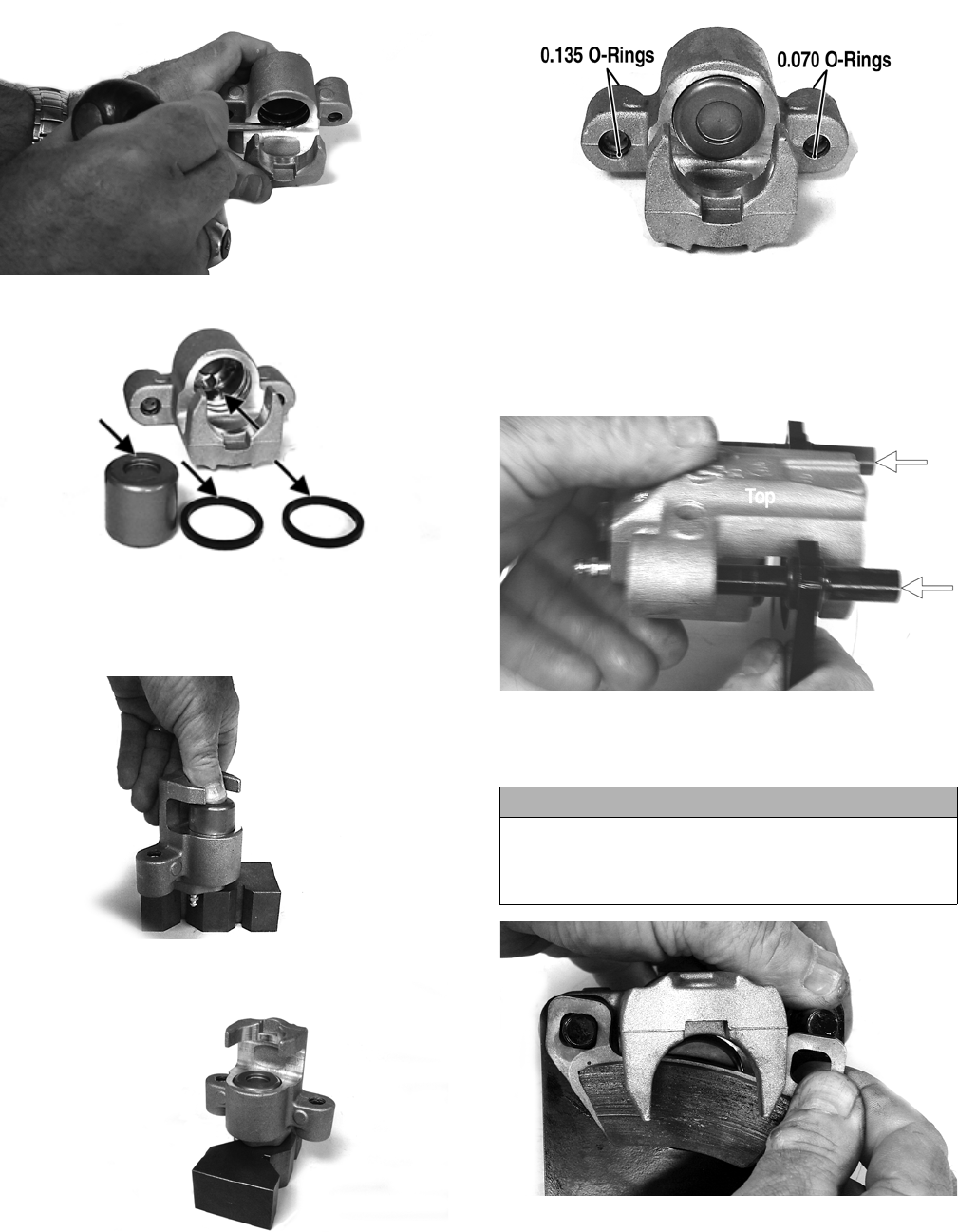
143
PR715
PR717A
2. Press the piston into the caliper housing using hand
pressure only. Completely seat the piston; then wipe
off any excessive brake fluid.
PR711A
PR712
3. Apply high-temperature silicone grease (supplied with
the O-ring kit) to the inside of the caliper holder bores
and O-rings; then install the four O-rings into the caliper.
PR719C
4. Install the caliper onto the caliper holder making sure
the caliper and holder are correctly oriented.
NOTE: It is very important to apply silicone grease
to the O-rings and caliper bores prior to assembly.
PR239C
5. Making sure brake fluid does not contact the brake pads,
compress the caliper holder toward the caliper and
install the inner brake pad; then install the outer pad.
PR238
CAUTION
If brake pads become contaminated with brake fluid, they
must be thoroughly cleaned with brake cleaning solvent
or replaced with new pads. Failure to do so will result in
reduced braking and premature brake pad failure.
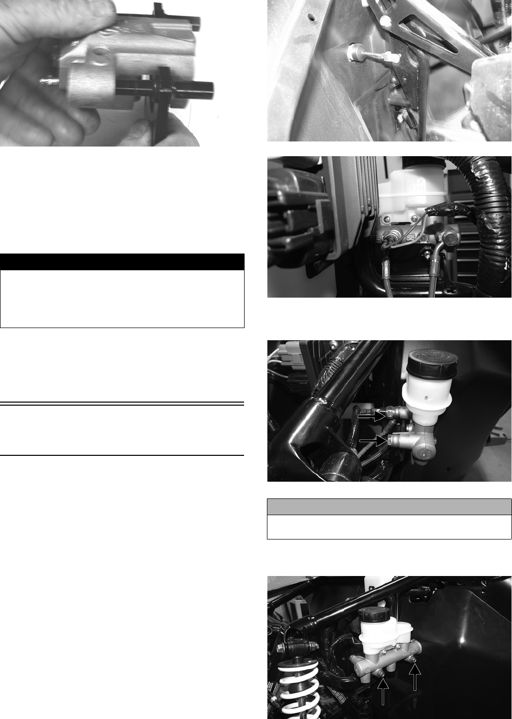
144
PR239
6. Place the brake caliper assembly into position and
secure with new “patch-lock” cap screws. Tighten the
caliper to 20 ft-lb.
7. Place a new crush washer on each side of the brake hose
fitting and install it on the caliper. Tighten to 20 ft-lb.
8. Fill the reservoir; then bleed the brake system (see
Periodic Maintenance/Tune-Up).
9. Install the wheel; then using a crisscross pattern,
tighten the wheel nuts in 20 ft-lb increments to a final
torque factor of 80 ft-lb.
10. Remove the vehicle from the support stand and verify
brake operation.
Master Cylinder
Assembly
NOTE: The master cylinder is a non-serviceable
component; it must be replaced as an assembly.
REMOVING
1. Slide a piece of flexible tubing over the front left
brake caliper bleeder valve and direct the other end
into a container. Remove the master cylinder cover;
then open the bleeder valve. Allow the brake fluid to
drain until the reservoir is empty.
2. Remove the cotter pin and pivot pin from the yoke; then
disconnect the two spade connectors from the switch.
WT514A
WT512
3. Remove the two banjo bolts securing the banjo fittings
to the master cylinder. Discard the four crush washers.
WT511A
4. Remove the two cap screws securing the master cylin-
der to the frame.
WT513A
! WARNING
Never use brake fluid from an open container or reuse
brake fluid. Moisture-contaminated brake fluid could cause
vapor build-up (expansion) during hard braking resulting in
greatly increased stopping distance or loss of control lead-
ing to injury or death.
CAUTION
Brake fluid is highly corrosive. Do not spill brake fluid
on any surface of the vehicle.
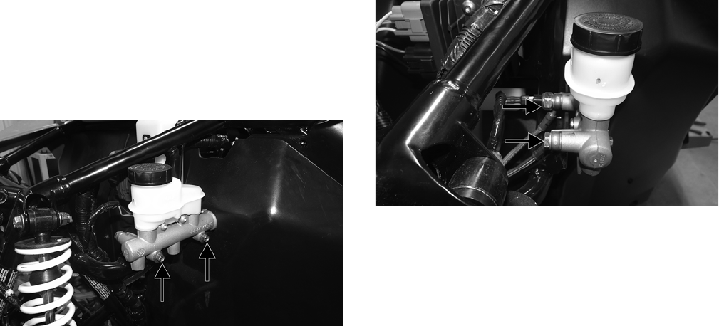
145
INSPECTING
1. Inspect the master cylinder push rod and clevis for
wear, bending, or elongation of clevis holes.
2. Inspect the push rod boot for tears or deterioration.
3. Inspect the reservoir for cracks and leakage.
4. Inspect the brake hose for cracks and deterioration and
the condition of the banjo-fittings.
INSTALLING
1. Place the master cylinder into position and secure with
cap screws. Tighten to 25 ft-lb.
WT513A
2. Install the pivot pin and secure with a new cotter pin;
then connect the switch.
3. Using four new crush washers installed on both sides
of the banjo fitting, secure the banjo bolts into the
master cylinder. Tighten to 20 ft-lb.
WT511A
4. Fill the master cylinder and bleed the brake system (see
Hydraulic Brake system in Periodic Maintenance/Tune-Up).

146
Troubleshooting
Problem: Power not transmitted from engine to wheels
Condition Remedy
1. Rear axle shaft serration worn - broken 1. Replace shaft
Problem: Power not transmitted from engine to either front wheel
Condition Remedy
1. Gear teeth broken
2. Front differential gears/pinions broken - damaged
3. Front drive actuator not operating
1. Replace gear(s)
2. Replace gears - pinions
3. Replace fuse - drive select switch - front drive actuator
Problem: Engine noisy (Noise seems to come from secondary bevel gear and final driven shaft)
Condition Remedy
1. Backlash excessive
2. Tooth contact improper
3. Bearing damaged
4. Gears worn - chipped
5. Splines worn
1. Adjust backlash
2. Adjust contact
3. Replace bearing
4. Replace gears
5. Replace shaft(s)
Problem: Braking poor
Condition Remedy
1. Pad worn
2. Brake fluid leaking
3. Master cylinder/brake cylinder seal worn
1. Replace pads
2. Repair leak(s)
3. Replace seal(s)
Problem: Brake pedal travel excessive
Condition Remedy
1. Brake fluid low
2. Piston seal - cup worn
1. Add fluid to proper level
2. Replace seal - cup
Problem: Brake fluid leaking
Condition Remedy
1. Fittings loose
2. Hose cracked
3. Piston seal worn
1. Tighten fittings
2. Replace hose
3. Replace seal
Problem: Brake pedal spongy
Condition Remedy
1. Air trapped in hydraulic system
2. Brake fluid low
1. Bleed hydraulic system
2. Add brake fluid and bleed hydraulic brake system
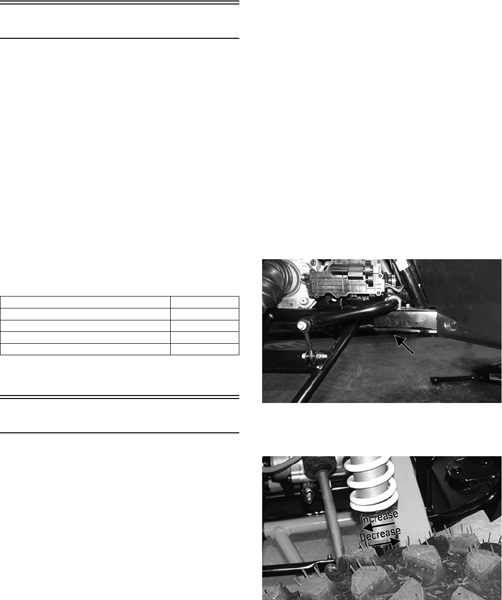
147
Suspension
The following suspension system components should be
inspected periodically to ensure proper operation.
A. Shock absorber rods bent, pitted, or damaged.
B. Reservoirs damp or leaking.
C. Shock absorber body damaged, punctured, or leaking.
D. Shock absorber eyelets broken, bent, or cracked.
E. Shock absorber eyelet bushings worn, deteriorated,
cracked, or missing.
F. Shock absorber spring broken or sagging.
G. Sway bar mountings tight and bushings secure.
H. Proper pre-load and damping for conditions.
SPECIAL TOOLS
A number of special tools must be available to the techni-
cian when performing service procedures in this section.
Refer to the current Special Tools Catalog for the appropri-
ate tool description.
NOTE: Special tools are available from the Arctic
Cat Service Department.
Shock Absorbers
REMOVING
1. Secure the vehicle on a support stand to elevate the
wheels and to release load on the suspension.
2. Remove the two cap screws and nuts securing each
front shock absorber to the frame and lower A-arm.
Account for bushings and sleeves from each.
3. Remove the two cap screws and nuts securing each
rear shock absorber to the frame and lower trailing
arm. Account for bushings and sleeves from each.
CLEANING AND INSPECTING
1. Completely remove pre-load by turning the adjusters
to the end of the threads and removing the retainer;
then remove the spring.
2. Clean all shock absorber components in parts-clean-
ing solvent.
3. Inspect each shock rod for nicks, pits, rust, bends, and
oily residue.
4. Inspect all springs, spring retainers, shock rods,
sleeves, bushings, shock bodies, and eyelets for
cracks, leaks, and bends.
INSTALLING
1. Place the shock absorber spring over the shock
absorber, compress the spring, and install the retainer.
2. Place bushings and sleeves (where appropriate) into
shock eyelet; then install shocks with two cap screws
and nuts.
3. Tighten the front shock absorber cap screws to 40 ft-lb
(head side). Tighten the upper rear shock absorber cap
screws to 40 ft-lb and the lower rear shock absorber
cap screws to 35 ft-lb.
4. Remove the vehicle from the support stand.
CHECKING/ADJUSTING RIDE
HEIGHT
NOTE: Ensure the vehicle is on level ground, the
tires are properly inflated to 14 psi, and there is an
average operating load in the vehicle.
1. Measure from the ground to the bottom of the skid
plate along the front sway bar. Measurement should be
10.5 inches.
WT492A
2. If measurement is not as specified, use an appropriate
spanner wrench to adjust the left and right spring as
required.
WT077B
3. Measure from the ground to the bottom of the skid
plate along the receiver hitch. Measurement should be
10 inches.
Description p/n
Shaft Bullet Tool 0644-404
Inflation Needle 0744-020
Piston Location (IFP) Tool 0644-575
Gas Shock Rod/Body Clamping Tool 0644-425
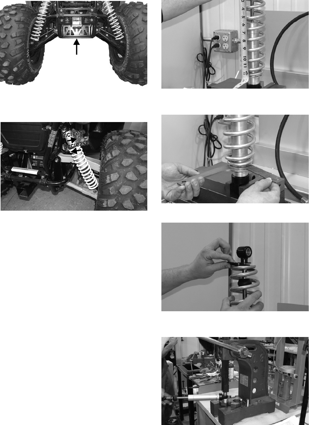
148
WT590A
4. If measurement is not as specified, use an appropriate
spanner wrench to adjust the left and right spring as
required.
WT078B
REBUILDING
Inspection
Inspect all components for any signs of wear or damage
and replace parts as necessary.
Preliminary Set-Up
1. Clean and dry the shock before beginning disassem-
bly.
2. Stroke the shock to assess its condition and function.
Compress and rebound adjustment positions should be
noted.
NOTE: This is done by turning the adjustment
knobs clockwise while counting the number of clicks
until the adjustment knob is fully closed or bottomed.
There are six clicks per full 360° revolution of the
adjustment knob. After noting positions, open all
adjustment knobs by turning them counter-clockwise
fully open.
NOTE: Throughout all procedures as a general rule,
replace all volatile parts (seals, O-rings, bearings,
etc.).
DISASSEMBLING
NOTE: Measure spring preload before removing the
spring.
FX068
1. Loosen the spring preload adjuster rings with spanner
wrenches.
FX067
2. Remove the spring retainer and spring.
FX066
3. Press the rubber-bonded bushing out from the body
end cap and eyelet bushings.
FX065
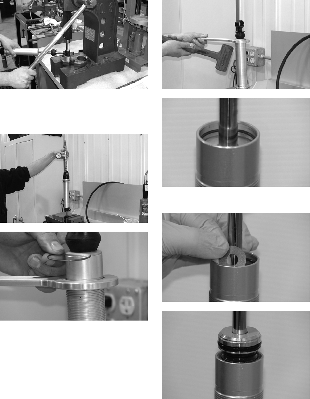
149
FX064
4. Secure the shock eyelet in the vise and insert the nitro-
gen needle. Fully depress the needle to release nitro-
gen pressure from the shock. After installing the
appropriate body cap removal tool, insert the retaining
wire into the groove between the cap and body.
FX063
FX062
5. Tap upward on body cap removal tool to release cap;
then depress the bearing assembly to full expose
retaining wire.
FX061
FX060
6. Using a valve shim, remove the retaining wire and
pull the shaft assembly out of the body.
FX059
FX058
7. Dispose of used oil in an environmentally-acceptable
manner; then use a body clamp block to secure the
body in the vise.
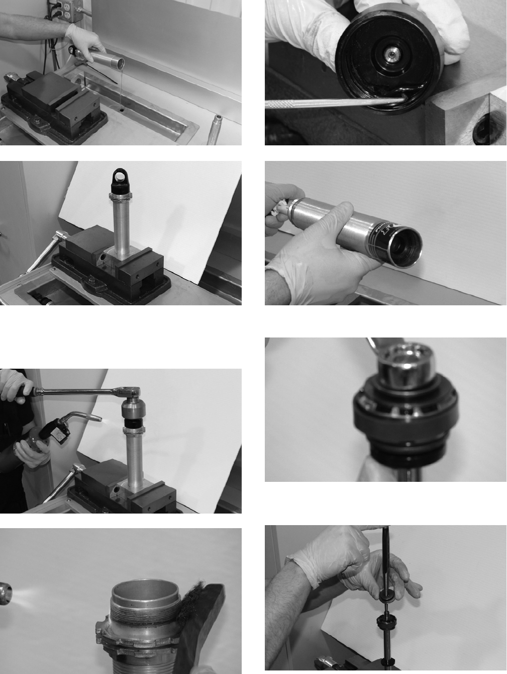
150
FX057
FX056
8. Apply sufficient heat to the body cap to break down
the thread lock bond between the body cap and body.
Remove any thread lock residue from the body and
body cap using a wire brush and small pick.
FX055
FX054
9. Remove the O-ring from the body cap; then push the
IFP out of body.
FX053
FX052
10. Remove the lock nut.
FX049
11. Remove the rebound valve stack and cable tie the
valves together.
FX048
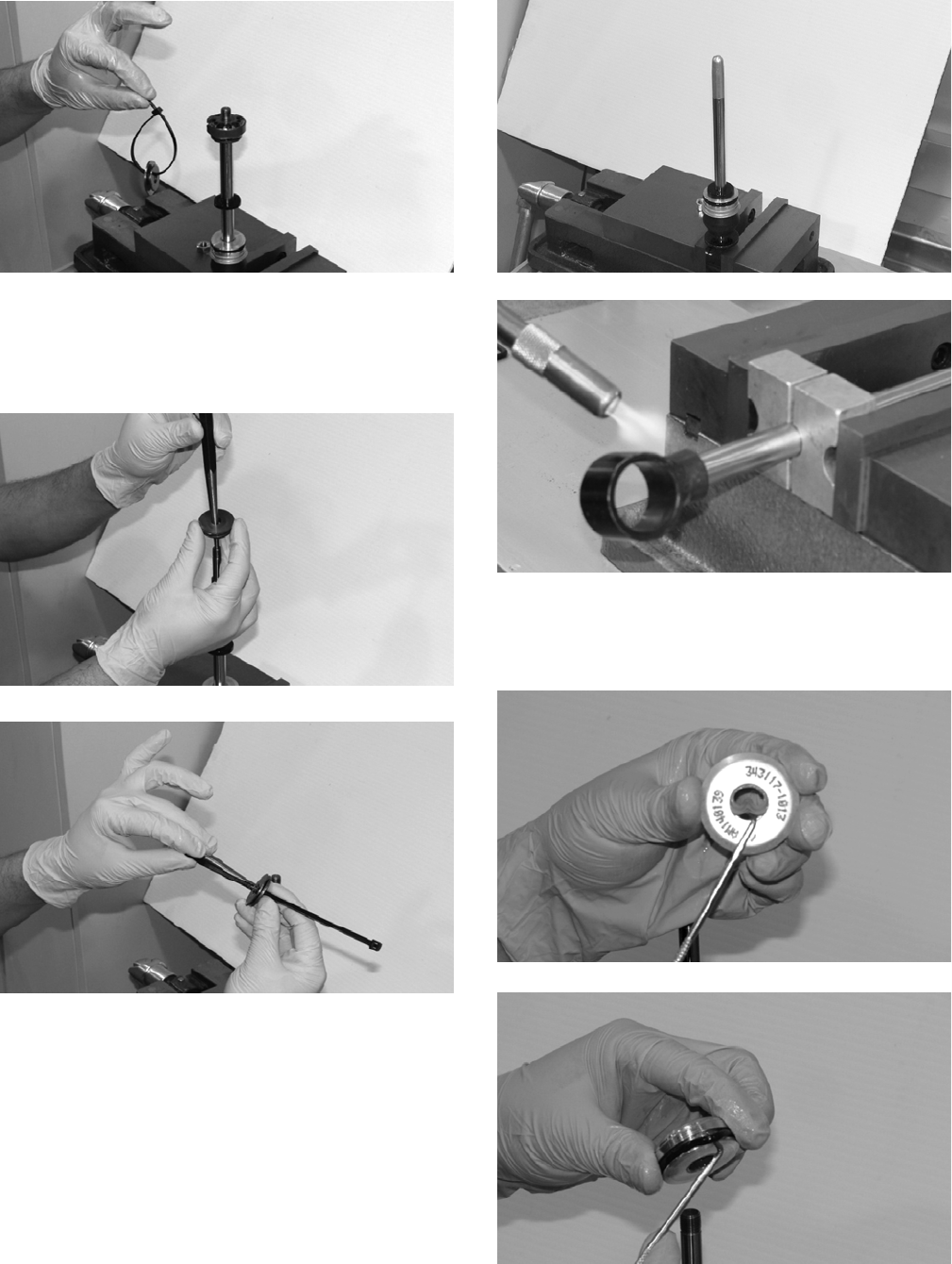
151
FX047
12. Remove the piston assembly; then remove the com-
pression valve stack and cable tie it together.
13. Remove the rubber washer, bearing assembly, bearing
cap, bumper, and washer.
FX044
FX043
14. Use Gas Shock Rod/Body Clamping Tool to secure
the shaft; then apply sufficient heat to the eyelet to
break the thread lock bond between the shaft and eye-
let.
FX042
FX041
15. Using a small pick, remove all seals and O-rings from
the bearing cap and bearing assembly. If a bearing is
required in the bearing assembly, replace the bearing
assembly.
FX040
FX039
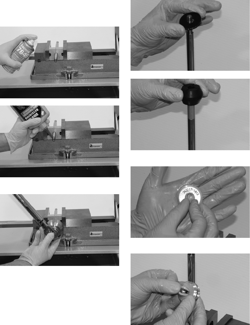
152
ASSEMBLING
1. Apply Loctite Primer #7649 to the shaft. Allow proper
curing time before applying green Loctite #638 to the
shaft.
FX038
FX037
2. Tighten to 50 ft-lb.
FX036
3. Assemble the shaft with eyelet washer and bumper.
NOTE: Always lubricate seals and O-rings with a
thin layer of molybdenum grease before installing.
FX035
FX034
4. Replace the wiper seal in the bearing cap.
FX033
5. Replace the U-cup seal and O-ring.
FX032
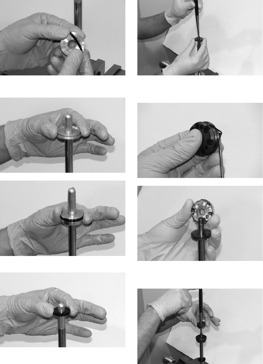
153
FX031
6. Using Shaft Bullet Tool, install the bearing cap assem-
bly and bearing assembly.
FX030
FX029
7. Install the bumper and compression valve stack.
FX028
FX027
8. Replace the O-ring and bearing on the piston. Install
the piston making sure the compression side of piston
is next to the compression shims.
FX026
FX025
9. Install the rebound valve stack; then replace the valve
stack. Replace the lock nut and tighten to 18 ft-lb. Set
aside for later assembly.
FX024

154
FX023
10. Replace the O-ring on the IFP. Apply a thin layer of
molybdenum grease to the body before installing the
IFP into the body with the IFP relief contour facing
towards the top of the body.
FX022
FX021
11. Apply Loctite Primer #7649 to the body and set the
IFP depth.
FX1020
FX019
NOTE: When setting IFP depth, note the shock
absorber IFP shuttles 0.480” during installation.
A. The designed depth of the IFP must be decreased
by 0.480” on the this shock absorber when the IFP
depth is determined from the top of the body.
B. Example: 8.164”-0.480” = 7.684” installed IFP
depth.
NOTE: Handle the body carefully once the IFP is
set.
12. Replace the O-ring in the body cap. If the shock has
been rebuilt several times, the body cap assembly may
need to be replaced.
FX018
13. Apply green Loctite #638 two threads wide for 360°
two threads up from the start of threads. Ensure the
Loctite does not make contact with the O-ring. Secure
the body in Gas Shock Rod/Body Clamping Tool and
tighten the body cap to 75 ft-lb.
FX017
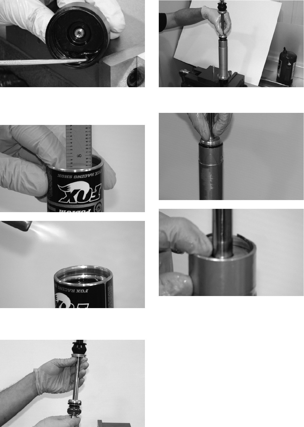
155
FX018
14. Verify the IFP depth is correct. Fill the body with
specified oil 3/8” from top of body. Pass a propane
torch quickly over the body to eliminate any air bub-
bles in oil.
FX015
FX014
15. Slide the bearing assembly to the bottom of shaft
before inserting. Insert the shaft assembly into the oil
slowly allowing air bubbles to escape.
FX013
FX012
16. Push the bearing assembly just past the retainer
groove in the body; then install the wire retainer.
FX011
FX010
17. Once the wire retainer is fully installed, slowly push
the shaft assembly down. DO NOT pull the shaft out.
Clean any excess oil off the body.
NOTE: If the shaft rebounds upward, it has hit the
IFP meaning the IFP will need to be reset.
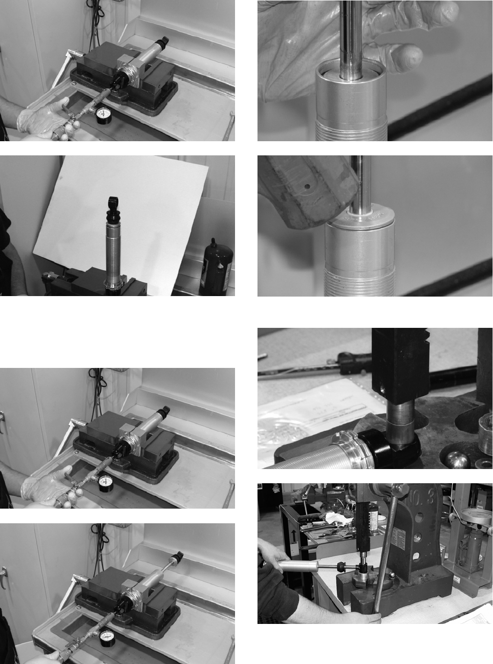
156
FX007
FX008
18. Secure the body with body clamps and ensure the
shaft has room to fully extend when charged. Charge
with nitrogen using Inflation Needle to the specified
pressure for about 10 seconds; the shaft should fully
extend.
FX007
FX006
19. Inspect both ends of shocks for leaks. Use rubber mal-
let to secure bearing cap assembly.
FX005
FX004
20. Install the body cap and eyelet bushings.
FX003
FX002
21. Clean the assembly and install the spring to the
desired preload setting.
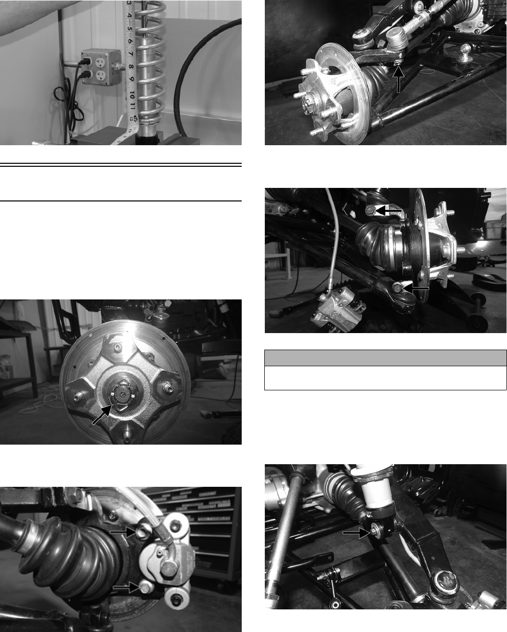
157
FX001
Front A-Arms
REMOVING UPPER
1. Lift and support the vehicle with a support stand to
allow access to the front suspension.
2. Remove the front wheels.
3. Remove the cotter pin and hub nut securing the hub.
WT328A
4. Remove and discard the “patch-lock” cap screws
securing the brake caliper to the hub.
WT287A
5. Remove the cotter pin and nut securing the tie rod end
to the knuckle; then remove the tie rod end from the
knuckle.
WT330A
6. Remove and discard the cap screws securing the ball
joints to the knuckle.
WT329A
7. Tap the ball joints out of the knuckle; then remove the
knuckle.
8. Remove and discard the cap screw securing the lower
shock eyelet to the upper A-arm. Remove the shock
from the A-arm.
WT498A
9. Remove the brakeline hose routing clip from the
upper A-arm; then remove the cap screw securing the
A-arm to the frame. Remove the A-arm.
NOTE: Having the steering rack turned completely
to the left and the clamp orientated as shown will aid
in removing the cap screw.
CAUTION
Support the knuckle when removing the cap screws or
damage to the threads will occur.
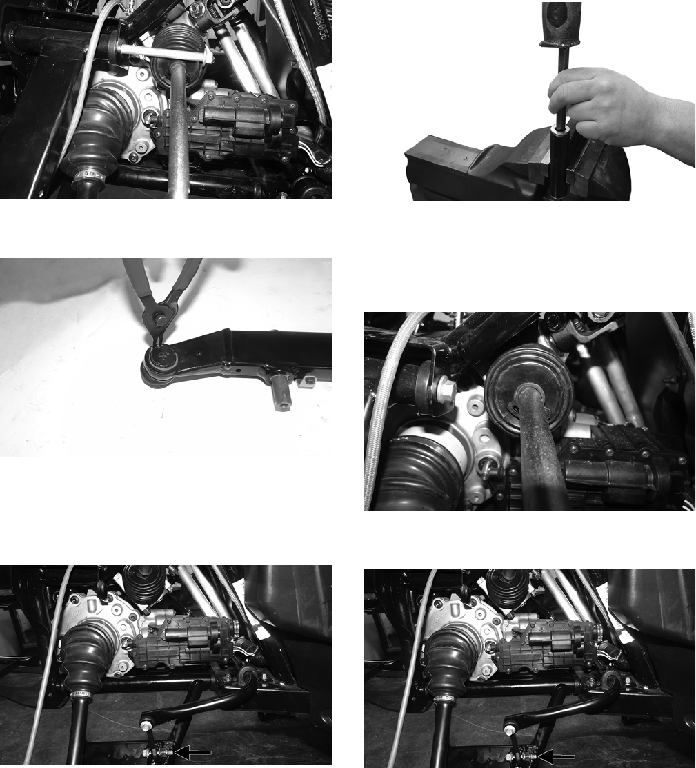
158
WT334
10. Remove the snap ring securing the ball joint in the A-
arm. Remove ball joint.
WT496
NOTE: Only remove the ball joint if replacement is
necessary.
11. Remove and discard the cap screw and lock nut secur-
ing the sway bar link to the lower A-arm.
WT494A
12. Remove the seals and sleeve and inspect for cracks,
nicks, or tears.
NOTE: Only remove the bushings if they must be
serviced.
13. Place the A-arm in a bench vise and using an appro-
priate tool, drive out and discard the bushings.
WT600
REMOVING LOWER
NOTE: Having the steering rack turned completely
to the left and the clamp orientated as shown will aid
in removing the cap screw.
WT333
1. Remove and discard the cap screw and lock nut secur-
ing the sway bar link to the lower A-arm.
WT494A
2. Remove the front bumper.
NOTE: The front bumper will need to be removed to
remove lower A-arm cap screw from frame.
3. Remove the cap screw and discard the lock nut secur-
ing the lower A-arm to the frame. Remove the A-arm.
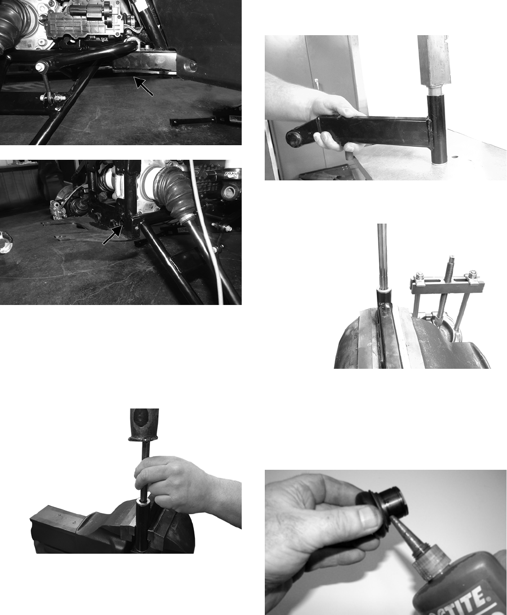
159
WT492A
WT493A
4. Remove the seals and sleeve and inspect for cracks,
nicks, or tears.
NOTE: Only remove the bushings if they must be
serviced.
5. Place the A-arm in a bench vise and using an appro-
priate tool, drive out and discard the bushings.
WT600
CLEANING AND INSPECTING
1. Clean all of the A-arm components in a parts-cleaning
solvent.
2. Clean the ball joint opening of all residual Loctite,
grease, oil, or dirt.
3. Inspect the A-arms for bends, cracks, and worn bush-
ings.
4. Inspect the ball joint mounting holes for cracks or
damage.
5. Inspect the frame mounts for signs of damage, wear,
or weldment damage.
INSTALLING
1. Using a suitable press, press in the new bushing.
WT599
2. Place the A-arm in a bench vise and using a 16 mm
reamer, ream out the bushings.
WT596
3. Insert the sleeve into the A-arm and apply molybde-
num grease to the inside of the seals. Install the seals
on the A-arm.
4. Apply Loctite Primer “T” to the A-arm socket; then
apply Green Loctite #609 to the entire outside diame-
ter of the ball joint. Install the ball joint into the A-arm
and secure it with the snap ring.
WC237
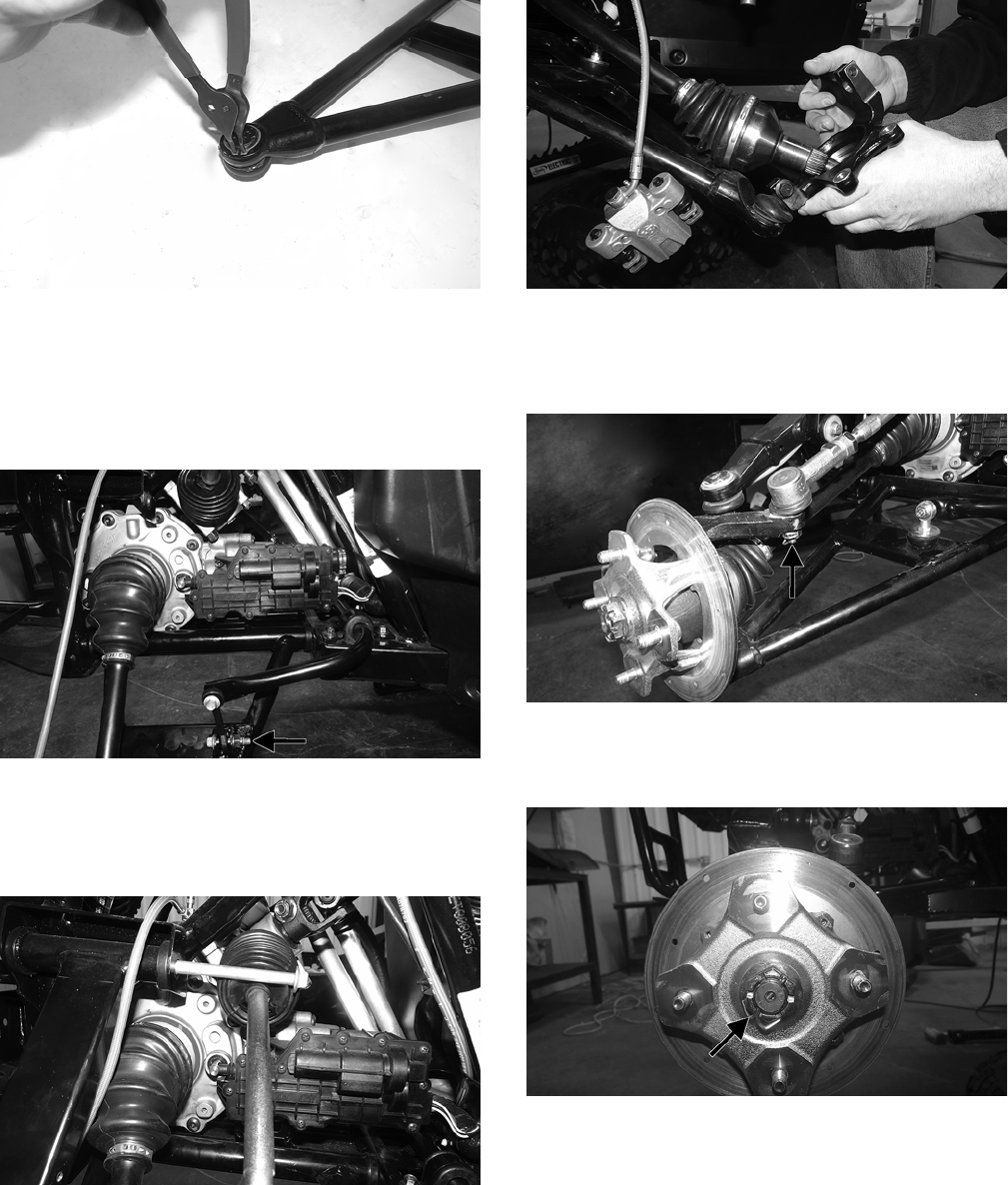
160
WT497
5. Install the lower A-arm into the frame mounts and
secure it with the cap screw and new lock nut. Finger-
tighten only at this time.
6. With a new “patch-lock” cap screw and new lock nut,
secure the sway bar link to the lower A-arm. Tighten
to 20 ft-lb.
WT494A
7. Tighten the lower A-arm cap screw to 40 ft-lb.
8. Install the upper A-arm to the frame with the cap
screw and new lock nut. Finger-tighten only at this
point.
WT334
9. Route the brakeline hose underneath the upper A-arm
and secure it with the clip. Tighten to 30 in.-lb.
10. Install the knuckle on the lower ball joint using a new
“patch-lock” cap screw. Finger-tighten only at this
time. With the axle going through the center of the
knuckle, rotate it upward and secure the upper A-arm
to the knuckle using a new “patch-lock” cap screw.
Tighten the cap screws to 35 ft-lb.
WT332
11. Install the tie rod end and secure it with the castle nut
(coated with red Loctite #271). Tighten to 55 ft-lb;
then install a new cotter pin and spread the pin to
secure the nut.
WT330A
12. Install the hub assembly and secure it with the hub
nut. Tighten to 200 ft-lb and install the new cotter pin.
Spread the pin to secure the nut.
WT328A
NOTE: During assembly, new cotter pins should
always be used.
NOTE: If the cotter pin cannot be inserted due to
misalignment of the hole and the slots in the nut,
always tighten the nut until it is properly aligned.
13. Using a new “patch-lock” cap screw and existing
washer, secure the shock to the upper A-arm. Tighten
to 25 ft-lb.
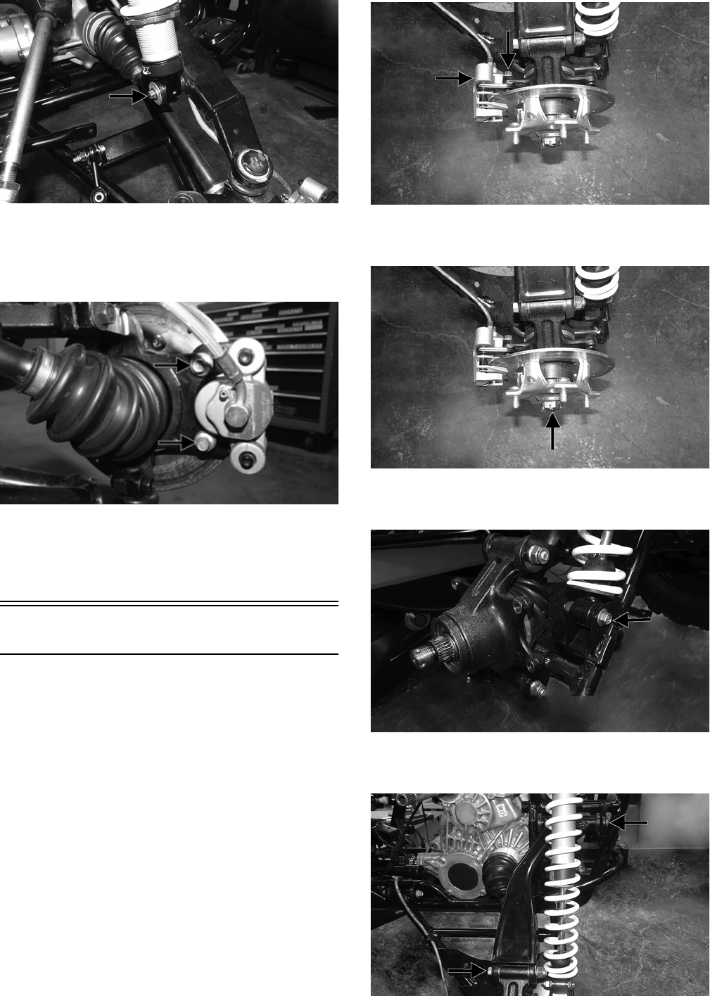
161
WT498A
14. Tighten the cap screw securing the upper A-arm to the
frame to 35 ft-lb.
15. Using new “patch-lock” cap screws, secure the brake
caliper to the brake disc. Tighten to 20 ft-lb.
WT287A
16. Install the wheels and tighten to 40 ft-lb (steel wheel)
or 80 ft-lb (aluminum wheel).
17. Install the front bumper; then remove the vehicle from
the support stand.
Rear A Arms
REMOVING
1. Lift and support the vehicle on a support stand that
allows access to the rear suspension with the rear tires
off of the floor. Remove the wheels.
NOTE: The upper A-arm can be removed without
removing the hub or the knuckle. If it is the techni-
cian’s objective to only remove the upper A-arm, pro-
ceed to step 5.
2. Remove and discard the “patch-lock” cap screws
securing the brake caliper to the hub.
WT418A
3. Remove and discard the cotter pin from the hub nut;
then remove nut and hub.
WT418B
4. Remove the lower shock cap screw and discard the
nut.
WT417A
5. Remove the cap screws securing the upper A-arm to
the frame and knuckle. Discard the nuts.
WT447A
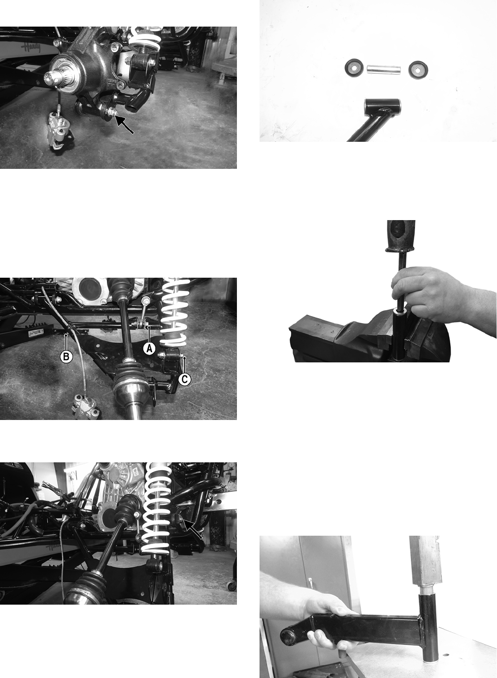
162
6. Remove the cap screw securing the lower A-arm to
the hub. Discard the nut.
W446A
NOTE: The drive axle does not have to be removed
for this procedure.
7. Remove and discard the cap screw and lock nut secur-
ing the sway bar link to the lower A-arm (A). Remove
the cap screw and clip securing the brake line to the
lower A-arm (B); then remove the cap screw and nut
securing the shock to the lower A-arm (C).
WT448A
8. Remove the cap screws and nuts securing the lower
A-arm to the frame. Discard the nuts.
WT445A
9. Remove the seals and sleeve.
WT444
NOTE: Only remove the bushings if they must be
serviced.
10. Place the A-arm in a bench vise and using an appro-
priate tool, drive out and discard the bushings.
WT600
CLEANING AND INSPECTING
1. Clean all A-arm components in parts-cleaning solvent.
2. Inspect the A-arm for bends, cracks, and worn bush-
ings.
3. Inspect the frame mounts for signs of damage, wear,
or weldment damage.
INSTALLING
NOTE: If only the upper A-arm was removed, skip to
step 6.
1. Using a suitable press, press in the new bushing.
WT599
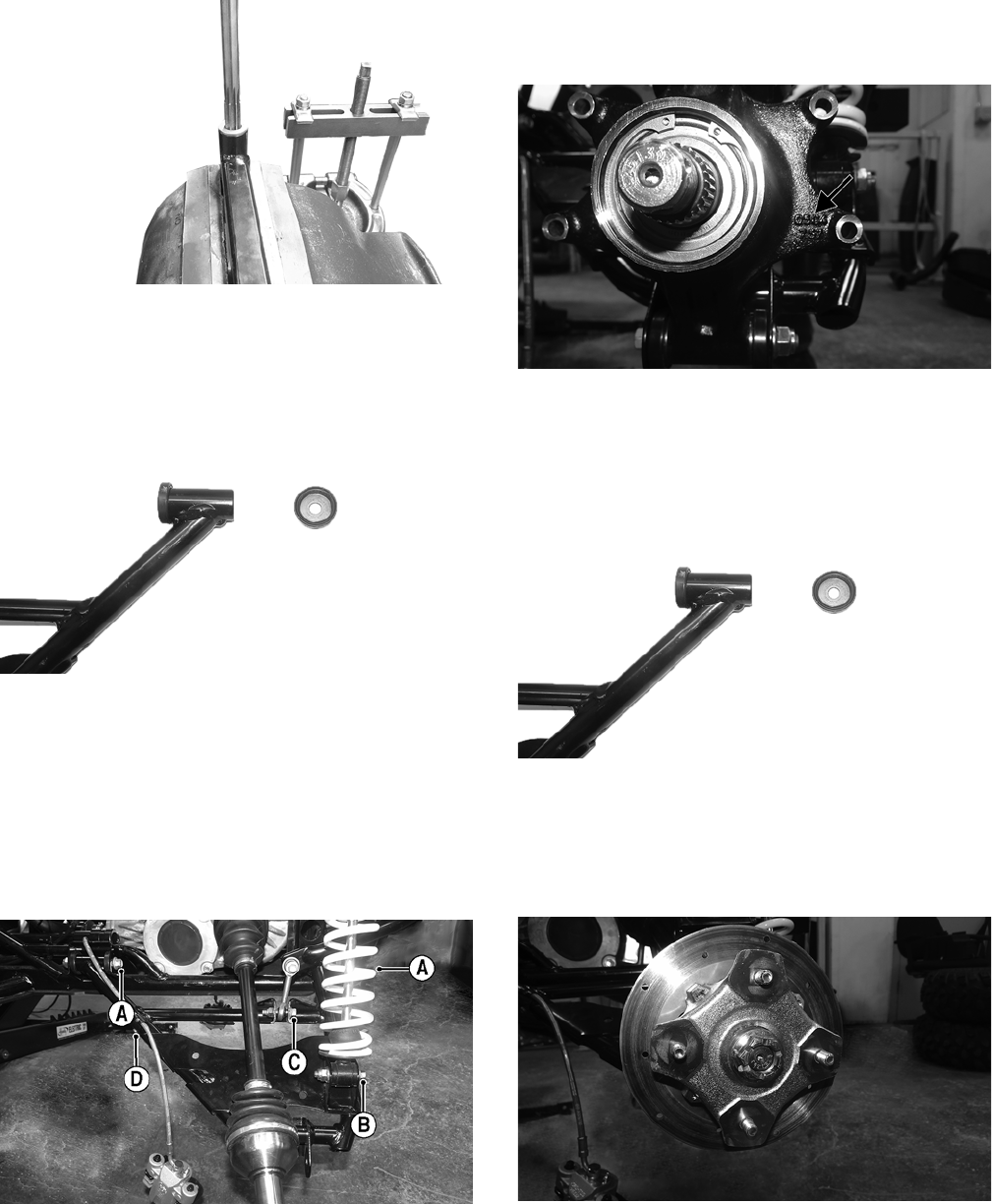
163
2. Place the A-arm in a bench vise and using a 16 mm
reamer, ream out the bushings.
WT596
3. Insert the sleeve into the A-arm; then apply grease to
the seal and insert it into the end of the A-arm along
with the end caps.
WT449
4. Install the lower A-arm into the frame mount and
secure with cap screws and new lock nuts (A). Only
finger tighten at this point. Install the shock into the
lower A-arm and secure it with the cap screw and new
lock nut (B). Only finger tighten at this point. Install
the sway bar link into the lower A-arm and secure it
with the new “patch-lock” cap screw and lock nut (C).
Only finger tighten at this point. Install the cap screw
and clip securing the brake line to the lower A-arm
(D).
WT448B
5. Tighten cap screw (A) to 35 ft-lb, cap screw (B) to 35
ft-lb, cap screw (C) to 20 ft-lb, and cap screw (D) to
20 in.-lb.
6. Using the existing cap screws and new lock nuts,
secure the knuckle to the upper and lower A-arms.
Tighten to 35 ft-lb.
NOTE: It is important that the hub is installed in a
manner that allows you to read the text.
WT450A
7. If the upper A-arm was removed, insert the sleeve into
the end of the upper A-arm. Apply grease to the seals
and install into the A-arm.
WT449
8. Install the upper A-arm into the frame. Mount and secure
the hub with the cap screws and new locking nuts.
9. Install the hub assembly and using an appropriate
spanner wrench, secure the hub to the axle with the
castle nut. Tighten to 200 ft-lb.
WT451
10. Install a new cotter pin and spread the pin to secure
the nut.
NOTE: If the pin does not line up with the castle nut,
always tighten the nut to the next opening and install
the pin.
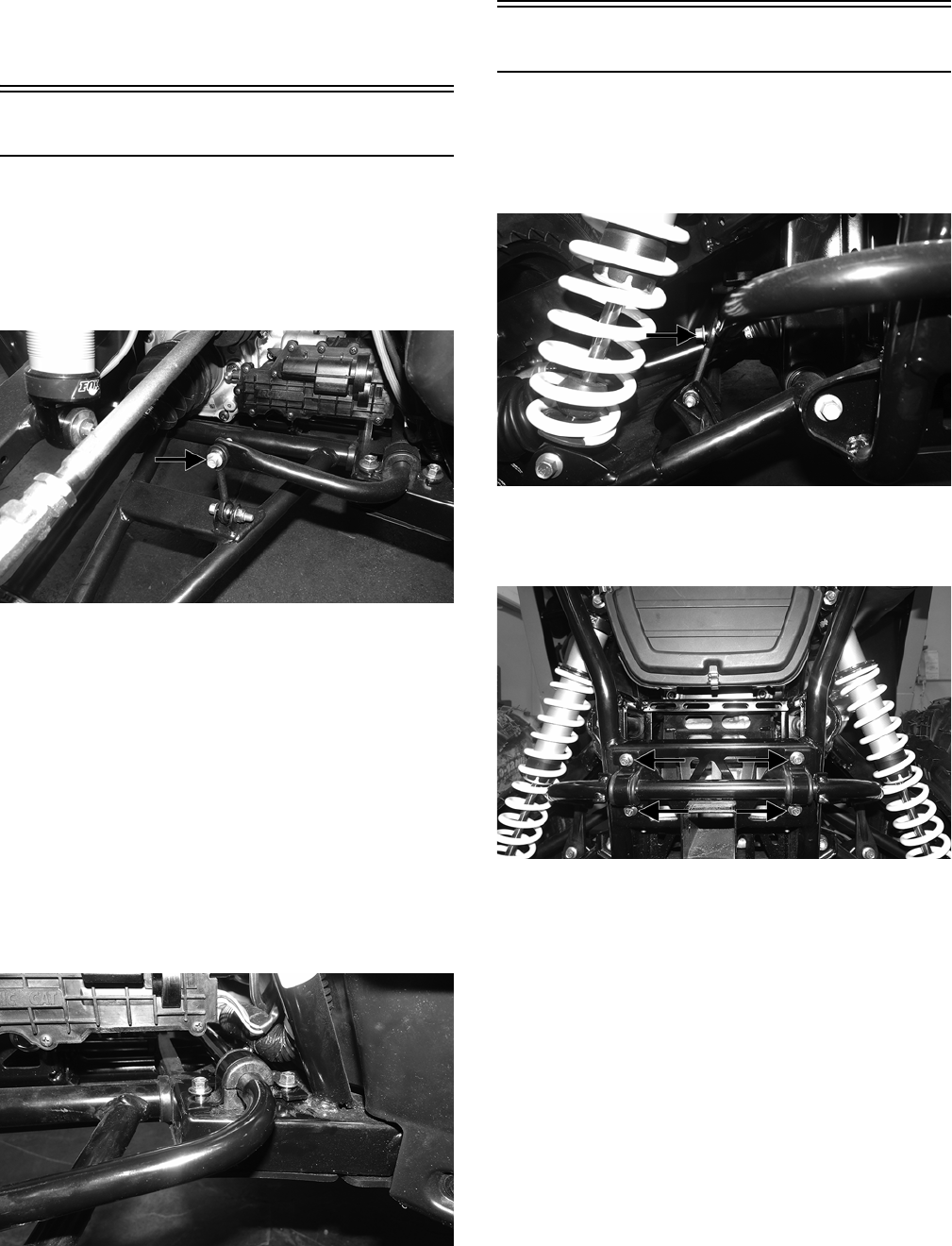
164
11. Using new “patch-lock” cap screws, install the brake
caliper and tighten to 20 ft-lb.
12. Install the wheel and tighten the lug nuts to 40 ft-lb
(steel wheels) or 80 ft-lb (aluminum wheels).
13. Remove the vehicle from the stand.
Front Sway Bar
REMOVING
1. Remove the front wheels (see Wheels and Tires in this
section).
2. Remove and discard the cap screws and lock nuts
securing the sway bar to the A-arm links.
WT323A
3. Remove the sway bar bushing retainers and bushings
and slide the sway bar out of the vehicle.
INSPECTING
1. Inspect the sway bar for any signs of twisting or
cracking.
2. Inspect the bushing retainers and bushings for any
signs of wear or damage.
INSTALLING
1. Using new “patch-lock” cap screws and new lock
nuts, install the sway bar into position and secure it to
the lower A-arm links.
2. Install the bushing retainers and bushings. Finger-
tighten the cap screws only at this point.
WT324
2. Tighten the A-arm links to 20 ft-lb; then tighten the
sway bar link to 35 ft-lb.
Rear Sway Bar
REMOVING
1. Remove and discard the cap screws and lock nuts
securing the sway bar link to the lower A-arms on
both sides.
WT320A
2. Remove the cap screws securing the sway bar to the
frame and remove the sway bar. Account for the bush-
ing retainers and bushings.
WT315B
INSPECTING
1. Inspect the sway bar for any signs of twisting or
cracking.
2. Inspect the bushing retainers and bushings for any
signs of wear or damage.
INSTALLING
1. Using new “patch-lock” cap screws and new lock
nuts, secure the sway bar to the lower A-arm link. Fin-
ger-tighten only at this point.
2. Install the bushings and bushing retainers. Finger-
tighten only at this point.
3. Tighten the lower A-arm links to 20 ft-lb; then tighten
the sway bar link to 35 ft-lb.

165
Wheels and Tires
TIRE SIZE
The Wildcat Trail is equipped with low-pressure tubeless
tires of the size and type listed in General Information. Do
not under any circumstances substitute tires of a different
type or size.
TIRE INFLATION PRESSURE
Front and rear tire inflation pressure should be as specified in
the General Information section.
REMOVING
1. Secure the vehicle on a support stand to elevate the
wheels.
2. Remove the nuts securing the wheels; then remove the
wheels.
CLEANING AND INSPECTING
1. Clean the wheels and hubs with parts-cleaning solvent.
2. Clean the tires with soap and water.
3. Inspect each wheel for cracks, dents, or bends.
4. Inspect each tire for cuts, wear, missing lugs, and leaks.
INSTALLING
Install the wheel; then using a crisscross pattern, tighten the
wheel nuts in 20 ft-lb increments to 40 ft-lb (steel wheel) 80 ft-
lb (aluminum wheel).
CHECKING/INFLATING
1. Using an air pressure gauge, measure the air pressure in
each tire. Adjust the air pressure as necessary to meet the
recommended inflation pressure.
2. Inspect the tires for damage, wear, or punctures.
NOTE: If repair is needed, follow the instructions found
on the tire repair kit or replace the tire.
Troubleshooting
! WARNING
Use only Arctic Cat approved tires when replacing tires.
Failure to do so could result in unstable vehicle operation.
! WARNING
Always use the size and type of tires specified. Always
maintain proper tire inflation pressure.
CAUTION
Do not mix tire tread patterns. Use the same pattern type
on front and rear. Failure to heed warning could cause
poor handling qualities of the vehicle and could cause
excessive drive train damage not covered by warranty.
! WARNING
Do not operate the vehicle if tire damage exists.
Problem: Suspension too soft
Condition Remedy
1. Spring preload incorrect
2. Spring(s) weak
3. Shock absorber damaged
1. Adjust preload
2. Replace spring(s)
3. Replace shock absorber
Problem: Suspension too stiff
Condition Remedy
1. Spring preload incorrect
2. A-arm-related bushings worn
1. Adjust preload
2. Replace bushing
Problem: Suspension noisy
Condition Remedy
1. Cap screws (suspension system) loose
2. A-arm-related bushings worn
1. Tighten cap screws
2. Replace bushings
Problem: Vehicle pulling or steering erratic
Condition Remedy
1. Vehicle steering is erratic on dry, level surface
2. Vehicle pulls left or right on dry, level surface
1. Check front wheel alignment and adjust if necessary (see
Steering/Frame/Controls)
2. Check air pressure in tires and adjust to specifications

Printed in U.S.A. Trademarks of Arctic Cat Inc., Thief River Falls, MN 56701 p/n 2260-145
