BAS 342G PS INSTRUCTIONS
2016-10-15
: Manual Bas-342G Ps Instructions BAS-342G PS_INSTRUCTIONS BROTHER
Open the PDF directly: View PDF ![]() .
.
Page Count: 86
- COVER
- SAFETY INSTRUCTIONS
- CONTENTS
- 1. NAMES OF MAJOR PARTS
- 2. SPECIFICATIONS
- 3. TABLE PROCESSING DIAGRAM
- 4. INSTALLATION
- 4-1. Removing the machine head fixing bolts [1]
- 4-2. Installing the control box [2]
- 4-3. Installing the oil pan and support lever base
- 4-4. Installing the machine head
- 4-5. Tilting back and returning the machine head
- 4-6. Installing the gas spring
- 4-7. Installing the operation panel [3]
- 4-8. Installing the solenoid valve assembly
- 4-9. Connecting the air tubes [4]
- 4-10. Installing the air hose [5]
- 4-11. Adjusting the air pressure [6]
- 4-12. Adjusting the speed controller [7]
- 4-13. Connecting the cords [8]
- 4-14. Connecting the ground wire [9]
- 4-15. Securing the cords and air tubes [10]
- 4-16. Installing the eye guard [11]
- 4-17. Installing the cotton stand [12]
- 4-18. Lubrication [13]
- 4-19. Connecting the power cord [14]
- 4-20. Checking the safety switch [15]
- 5. PREPARATION BEFORE SEWING
- 6. USING THE OPERATION PANEL (BASIC OPERATIONS)
- 7. USING THE OPERATION PANEL (ADVANCED OPERATIONS)
- 7-1. List of advanced functions
- 7-2. Setting memory switches
- 7-3. List of memory switch settings
- 7-4. Using the lower thread counter
- 7-5. Using the production counter
- 7-6. Setting the split number
- 7-7. Using user programs
- 7-8. Using cycle programs
- 7-9. Direct selection (combination table)
- 7-10. X and Y parallel movement of sewing pattern
- 7-11. Clearing memory data (reinitialization)
- 8. USING CF CARDS
- 9. SEWING
- 10. CLEANING
- 11. STANDARD ADJUSTMENTS
- 11-1. Adjusting the thread take-up spring
- 11-2. Adjusting arm thread guide R
- 11-3. Adjusting the needle bar height
- 11-4. Adjusting the needle bar lift amount
- 11-5. Adjusting the driver needle guard
- 11-6. Adjusting the needle clearance
- 11-7. Adjusting the inner rotary hook and hook stopper overlap
- 11-8. Adjusting the rotary hook lubrication amount
- 11-9. Adjusting the position of the movable knife
- 11-10. Replacing the movable and fixed knives
- 11-11. Adjusting the thread wiper
- 11-12. Presser foot installation position
- 11-13. Changing the intermittent stroke
- 11-14. Adjusting the work clamp lift amount
- 11-15. Adjusting the air pressure
- 12. TABLE OF ERROR CODES
- 13. TROUBLESHOOTING
- 14. 7-SEGMENT DISPLAY
- END COVER
BAS-342G PS
Please read this manual before using the machine.
Please keep this manual within easy reach for quick reference.
DIRECT DRIVE
PROGRAMMABLE ELECTRONIC PATTERN SEWER
<PERFECT STITCH>
INSTRUCTION MANUAL
BAS-342G PS
Thank you very much for buying a BROTHER sewing machine. Before using your new machine,
please read the safety instructions below and the explanations given in the instruction manual.
With industrial sewing machines, it is normal to carry out work while positioned directly in front of
moving parts such as the needle and thread take-up lever, and consequently there is always a
danger of injury that can be caused by these parts. Follow the instructions from training personnel
and instructors regarding safe and correct operation before operating the machine so that you will
know how to use it correctly.
BAS-342G PS i
SAFETY INSTRUCTIONS
[1] Safety indications and their meanings
This instruction manual and the indications and symbols that are used on the machine itself are provided in order to ensure
safe operation of this machine and to prevent accidents and injury to yourself or other people.
The meanings of these indications and symbols are given below.
Indications
DANGER The instructions which follow this term indicate situations where failure to follow the
instructions will result in death or serious injury.
CAUTION The instructions which follow this term indicate situations where failure to follow the
instructions may result in minor or moderate injury.
IMPORTANT The instructions which follow this term indicate situations where failure to follow the
instructions may result in physical damage to equipment and surroundings or result in
problems with equipment operation.
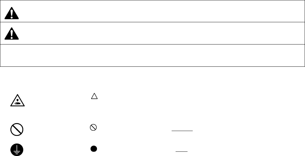
Symbols
・・・・・・ This symbol ( ) indicates something that you should be careful of. The picture inside the triangle
indicates the nature of the caution that must be taken.
(For example, the symbol at left means “beware of injury”.)
・・・・・・ This symbol ( ) indicates something that you must not do.
・・・・・・ This symbol ( ) indicates something that you must do. The picture inside the circle indicates the
nature of the thing that must be done.
(For example, the symbol at left means “you must make the ground connection”.)
BAS-342G PS
ii
[2] Notes on safety
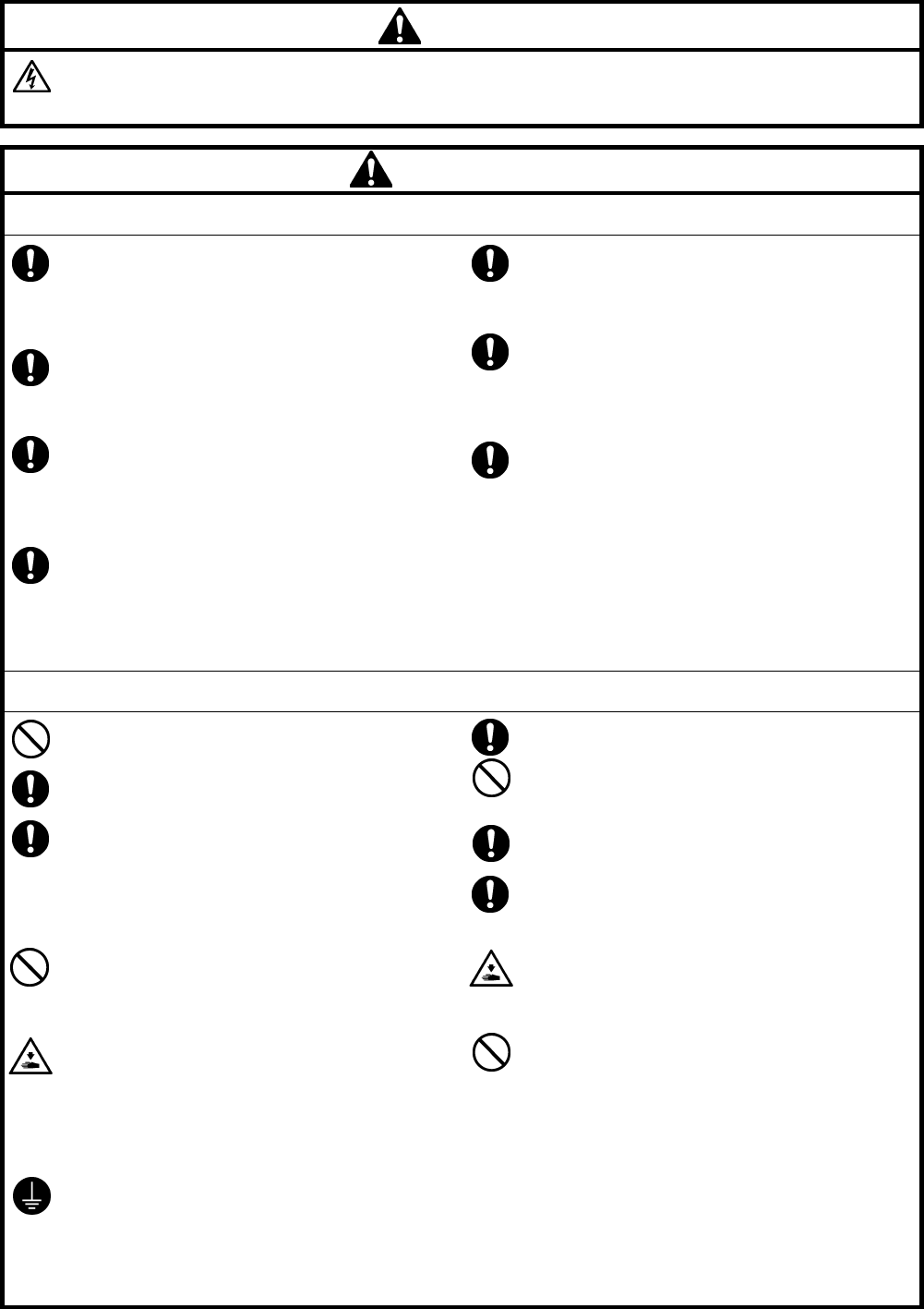
DANGER
Wait at least 5 minutes after turning off the power switch and disconnecting the power cord from the wall outlet
before opening the cover of the control box. Touching areas where high voltages are present can result in severe
injury.
CAUTION
Environmental requirements
Use the sewing machine in an area which is free from
sources of strong electrical noise such as electrical
line noise or static electric noise.
Sources of strong electrical noise may cause
problems with correct operation.
Any fluctuations in the power supply voltage should
be within ±10% of the rated voltage for the machine.
Voltage fluctuations which are greater than this may
cause problems with correct operation.
The power supply capacity should be greater than the
requirements for the sewing machine's power
consumption.
Insufficient power supply capacity may cause
problems with correct operation.
The pneumatic delivery capability should be greater
than the requirements for the sewing machine's total
air consumption.
Insufficient pneumatic delivery capability may cause
problems with correct operation.
The ambient temperature should be within the range
of 5°C to 35°C during use.
Temperatures which are lower or higher than this
may cause problems with correct operation.
The relative humidity should be within the range of
45% to 85% during use, and no dew formation should
occur in any devices.
Excessively dry or humid environments and dew
formation may cause problems with correct operation.
In the event of an electrical storm, turn off the power
and disconnect the power cord from the wall outlet.
Lightning may cause problems with correct operation.
Installation
Machine installation should only be carried out by a
qualified technician.
Contact your Brother dealer or a qualified electrician
for any electrical work that may need to be done.
The sewing machine weighs approximately 160 kg.
Use equipment such as a crane or hoist when
installing the machine head and adjusting the height
of the table.
If you try to lift the machine head yourself, it may
cause injuries such as back injury.
Do not connect the power cord until installation is
complete. If the foot switch is depressed by mistake,
the sewing machine might start operating and injury
could result.
Hold the machine head with both hands when tilting it
back or returning it to its original position.
In addition, do not subject the machine head to extra
force while it is tilted back. If this is not observed, the
machine head may become unbalanced and fall
down, and serious injury or damage to the sewing
machine may result.
Be sure to connect the ground. If the ground
connection is not secure, you run a high risk of
receiving a serious electric shock, and problems with
correct operation may also occur.
All cords should be secured at least 25 mm away
from any moving parts. Furthermore, do not
excessively bend the cords or secure them too firmly
with staples, otherwise there is the danger that fire or
electric shocks could occur.
Install the safety covers to the machine head and
motor.
If using a work table which has casters, the casters
should be secured in such a way so that they cannot
move.
Use a table with a height of 84 cm or less. If the table
is too high, the machine head may become
unbalanced and fall down, and serious injury or
damage to the sewing machine may result.
Be sure to wear protective goggles and gloves when
handling the lubricating oil and grease, so that they
do not get into your eyes or onto your skin. If the oil
and grease get into your eyes or onto your skin,
inflammation can result.
Furthermore, do not drink or eat the lubricating oil or
grease. They may cause diarrhea or vomiting.
Keep the oil out of the reach of children.
BAS-342G PS iii
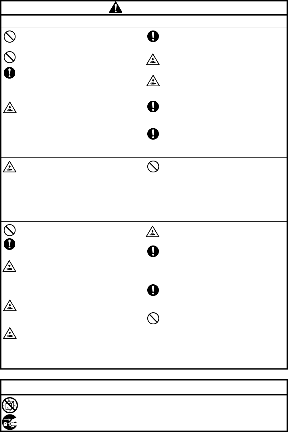
CAUTION
Sewing
This sewing machine should only be used by
operators who have received the necessary training
in safe use beforehand.
The sewing machine should not be used for any
applications other than sewing.
Be sure to wear protective goggles when using the
machine.
If goggles are not worn, there is the danger that if a
needle breaks, parts of the broken needle may enter
your eyes and injury may result.
Turn off the power switch at the following times. If the
foot switch is depressed by mistake, the sewing
machine might start operating and injury could result.
• When threading the needle
• When replacing the bobbin and needle
• When not using the machine and when leaving the
machine unattended
If using a work table which has casters, the casters
should be secured in such a way so that they cannot
move.
Attach all safety devices before using the sewing
machine. If the machine is used without these
devices attached, injury may result.
Do not touch any of the moving parts or press any
objects against the machine while sewing, as this
may result in personal injury or damage to the
machine.
If an error occurs in machine operation, or if abnormal
noises or smells are noticed, immediately turn off the
power switch. Then contact your nearest Brother
dealer or a qualified technician.
If the machine develops a problem, contact your
nearest Brother dealer or a qualified technician.
Cleaning
Turn off the power switch before carrying out
cleaning. If the foot switch is depressed by mistake,
the sewing machine might start operating and injury
could result.
Be sure to wear protective goggles and gloves when
handling the lubricating oil and grease, so that they
do not get into your eyes or onto your skin. If the oil
and grease get into your eyes or onto your skin,
inflammation can result.
Furthermore, do not drink or eat the lubricating oil or
grease. They may cause diarrhea or vomiting.
Keep the oil out of the reach of children.
Maintenance and inspection
Maintenance and inspection of the sewing machine
should only be carried out by a qualified technician.
Ask your Brother dealer or a qualified electrician to
carry out any maintenance and inspection of the
electrical system.
Turn off the power switch and disconnect the power
cord before carrying out the following operations. If
the foot switch is depressed by mistake, the sewing
machine might start operating and injury could result.
• Inspection, adjustment and maintenance
• Replacing consumable parts such as the rotary hook
Disconnect the air hoses from the air supply and wait
for the needle on the pressure gauge to drop to “0”
before carrying out inspection, adjustment and repair
of any parts which use the pneumatic equipment.
Hold the machine head with both hands when tilting it
back or returning it to its original position.
In addition, do not subject the machine head to extra
force while it is tilted back. If this is not observed, the
machine head may become unbalanced and fall
down, and serious injury or damage to the sewing
machine may result.
If the power switch and air need to be left on when
carrying out some adjustment, be extremely careful to
observe all safety precautions.
When replacing parts and installing optional
accessories, be sure to use only genuine Brother
parts.
Brother will not be held responsible for any accidents
or problems resulting from the use of non-genuine
parts.
If any safety devices have been removed, be
absolutely sure to re-install them to their original
positions and check that they operate correctly before
using the machine.
To prevent accidents and problems, do not modify
the machine yourself.
Brother will not be held responsible for any accidents
or problems resulting from modifications made to the
machine.
IMPORTANT
Do not allow any liquids to get onto this sewing machine, otherwise smoke or fire may occur.
If any liquid gets inside the sewing machine (machine head or control box), immediately turn off the power and
disconnect the power plug from the electrical outlet, and then contact the place of purchase or a qualified technician.
BAS-342G PS
iv
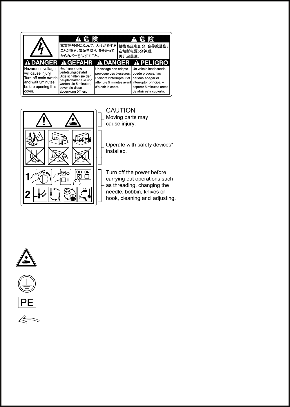
[3] Warning labels
The following warning labels appear on the sewing machine.
Please follow the instructions on the labels at all times when using the machine. If the labels have been removed or are
difficult to read, please contact your nearest Brother dealer.
1
2
3
4
5
Be careful to avoid getting hands caught in sliding parts.
Be sure to connect the ground. If the ground connection is not secure, you run a high risk of receiving
a serious electric shock, and problems with correct operation may also occur.
Direction of operation
*Safety devices
Devices such as eye guard, finger guard, thread take-up cover, motor cover, X motor cover,
tension release solenoid cover, inside cover, outside cover, middle cover, fixed cover and rear cover
BAS-342G PS v
2740B
Thread take-up cover
Finger guard
Inside cover R
Outside cover
Fixed cover
Eye guard
Middle cover
Rear cove
r
Rear cover
Tension release solenoid cover
Motor cover
Rear cove
r
Inside cover L
Outside cover
Fixed cover
Middle cove
r
X motor cover
BAS-342G PS
CONTENTS
1. NAMES OF MAJOR PARTS ................ 1
2. SPECIFICATIONS ................................ 2
3. TABLE PROCESSING DIAGRAM ....... 3
4. INSTALLATION.................................... 4
4-1. Removing the machine head fixing bolts [1]..... 4
4-2. Installing the control box [2].............................. 5
4-3. Installing the oil pan and support lever base.... 6
4-4. Installing the machine head.............................. 6
4-5. Tilting back and returning the machine head ... 7
4-6. Installing the gas spring.................................... 8
4-7. Installing the operation panel [3]....................... 9
4-8. Installing the solenoid valve assembly ............. 10
4-9. Connecting the air tubes [4].............................. 10
4-10. Installing the air hose [5]................................. 10
4-11. Adjusting the air pressure [6].......................... 11
4-12. Adjusting the speed controller [7] ................... 11
4-13. Connecting the cords [8]................................. 12
4-14. Connecting the ground wire [9] ...................... 14
4-15. Securing the cords and air tubes [10]............. 15
4-16. Installing the eye guard [11] ........................... 16
4-17. Installing the cotton stand [12]........................ 16
4-18. Lubrication [13] ............................................... 17
4-19. Connecting the power cord [14] ..................... 18
4-20. Checking the safety switch [15] ...................... 18
5. PREPARATION BEFORE SEWING.....19
5-1. Installing the needle.......................................... 19
5-2. Operating the 2-pedal foot switch..................... 19
5-3. Threading the upper thread .............................. 20
5-4. Winding the lower thread.................................. 22
5-5. Installing the bobbin case................................. 23
5-6. Thread tension.................................................. 24
5-6-1. Lower thread tension.............................. 24
5-6-2. Upper thread tension.............................. 24
5-7. Home position detection ................................... 25
5-8. Setting 2-step operation for the work clamp..... 26
6. USING THE OPERATION PANEL
(BASIC OPERATIONS) .......................27
6-1. Name and function of each operation
panel item..........................................................27
6-2. Loading sewing data .........................................29
6-3. Setting the program number .............................29
6-4. Setting the X-scale and Y-scale........................30
6-5. Setting the sewing speed..................................30
6-6. Checking the sewing pattern.............................31
6-7. Setting the height of the intermittent presser foot...32
7. USING THE OPERATION PANEL
(ADVANCED OPERATIONS) ..............33
7-1. List of advanced functions ................................33
7-2. Setting memory switches ..................................34
7-3. List of memory switch settings ..........................35
7-4. Using the lower thread counter .........................36
7-5. Using the production counter ............................37
7-6. Setting the split number ....................................38
7-7. Using user programs.........................................39
7-8. Using cycle programs .......................................42
7-9. Direct selection (combination table)..................44
7-10. X and Y parallel movement of sewing pattern ...45
7-11. Clearing memory data (reinitialization) ...........46
8. USING CF CARDS ...............................47
8-1. Notes on handling CF cards (sold separately) ...47
8-2. Structure of a CF card folder.............................47
8-3. Data read/write mode........................................48
8-3-1. Reading all sewing data from the
CF card at once ......................................49
8-3-2. Writing all sewing data to the CF card
at once ....................................................50
BAS-342G PS
9. SEWING................................................51
9-1. Sewing .............................................................. 51
9-2. Using the STOP switch..................................... 52
9-3. Using the thread wiper switch........................... 52
10. CLEANING .........................................53
10-1. Cleaning the rotary hook ................................ 53
10-2. Draining the oil................................................ 53
10-3. Checking the regulator ................................... 53
10-4. Cleaning the control box air inlet ports ........... 54
10-5. Cleaning the eye guard .................................. 54
10-6. Checking the needle....................................... 54
10-7. Lubrication ...................................................... 54
11. STANDARD ADJUSTMENTS ............55
11-1. Adjusting the thread take-up spring................ 55
11-2. Adjusting arm thread guide R......................... 56
11-3. Adjusting the needle bar height...................... 56
11-4. Adjusting the needle bar lift amount ............... 57
11-5. Adjusting the driver needle guard................... 57
11-6. Adjusting the needle clearance ...................... 58
11-7. Adjusting the inner rotary hook and
hook stopper overlap ...................................... 58
11-8. Adjusting the rotary hook lubrication amount... 58
11-9. Adjusting the position of the movable knife .... 59
11-10. Replacing the movable and fixed knives ...... 62
11-10-1. Installing the feed plate .................. 63
11-11. Adjusting the thread wiper............................ 63
11-12. Presser foot installation position................... 64
11-13. Changing the intermittent stroke .................. 64
11-14. Adjusting the work clamp lift amount............ 66
11-15. Adjusting the air pressure............................. 66
12. TABLE OF ERROR CODES...............67
13. TROUBLESHOOTING........................71
14. 7-SEGMENT DISPLAY.......................75
1. NAMES OF MAJOR PARTS
BAS-342G PS
1
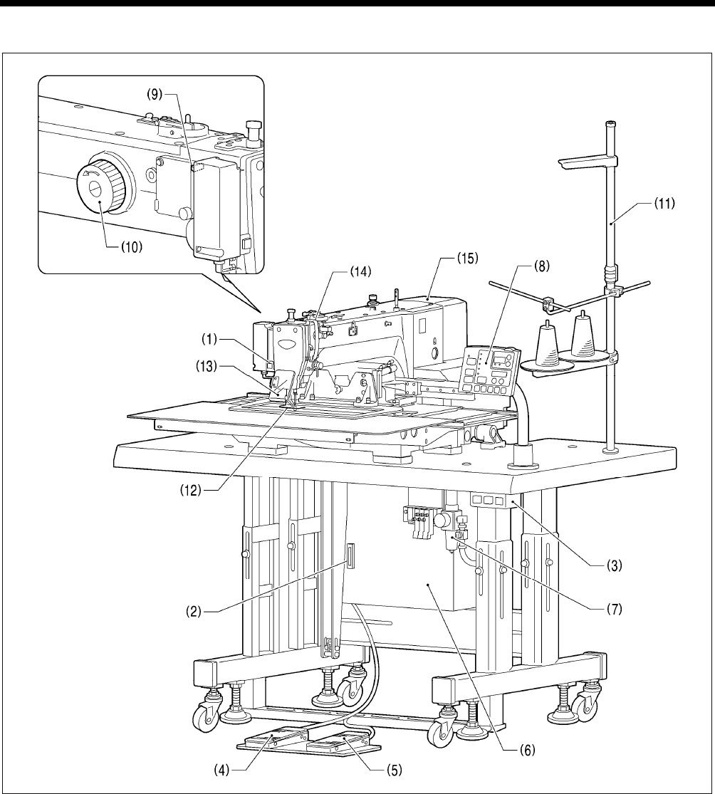
1. NAMES OF MAJOR PARTS
(1) STOP switch Safety devices:
(2) CF slot (12) Finger guard
(3) Power switch (13) Eye guard
(4) Work clamp switch (14) Thread take-up cover
(5) Start switch (15) Motor cover
(6) Control box
(7) Solenoid valve
(8) Operation panel
(9) Thread wiper switch
(10) Pulley
(11) Cotton stand
CFTM is a trademark of SanDisk Corporation.
2741B

2. SPECIFICATIONS
BAS-342G PS 2
2. SPECIFICATIONS
Sewing machine Lock stitch, pattern tacking sewing machine
Stitch formation Single needle lock stitch
Max. sewing speed 2,700 sti/min
Sewing area (X x Y) Max. 300 x 200 mm
Feed mechanism Intermittent feed, pulse motor drive
Stitch length 0.05 − 12.7 mm
No. of stitches 500,000-stitch internal memory (*1)
Maximum no. of stitches 20,000 stitches (per program)
No. of sewing data items
that can be stored Internal memory: 512 (*1), CF card: 900
Work clamp lift method Pneumatic method
Work clamp height Max. 30 mm
2-step work clamp Integrated-type work clamp
Intermittent presser foot lift
amount 19.5 mm
Intermittent stroke 2 − 4.5 mm, 4.5 − 10 mm or 0 (Default setting 3 mm)
Rotary hook Double-capacity rotary hook
Wiper device Standard equipment
Thread trimmer Standard equipment
Data storage method Internal memory (Flash memory), CF card (32 MB − 2 GB)
3.5 floppy disk 2HD/1.44MB, 2DD (*2)
User programs 50
Cycle programs 9
Motor 550 W AC servo motor
Weights Machine head approx. 160 kg, operation panel approx. 0.6 kg
Control box 14.2 − 16.2 kg (Differs depending on destination)
Power supply Single-phase 220 V, Three-phase 220 V/380 V/400 V 500 VA
Air pressure 0.5 MPa 1.8 l/min.
(*1) The number of data items and stitches that can be stored will vary depending on the number of stitches in each
program.
(*2) Supply of parts relating to 3.5-inch floppy disks has already been discontinued. (However the mechanism will still
function.)
3. TABLE PROCESSING DIAGRAM
3 BAS-342G PS
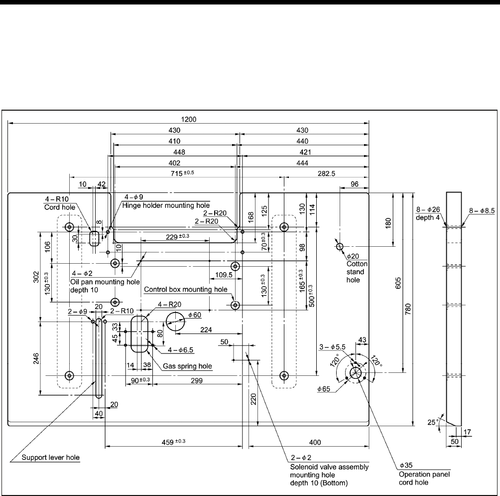
3. TABLE PROCESSING DIAGRAM
• The thickness of the table should be at least 50 mm, and it should be strong enough to bear the weight and vibration of the
sewing machine.
• If using casters, use ones which can bear the total weight of sewing machine and table.
• Check that the control box is at least 10 mm away from the leg. If the control box and the leg are too close together, it may result
in incorrect sewing machine operation.
4053
M
4. INSTALLATION
4
BAS-342G PS
4. INSTALLATION
CAUTION
Machine installation should only be carried out by a
qualified technician.
Contact your Brother dealer or a qualified electrician for
any electrical work that may need to be done.
The sewing machine head weighs approximately 160
kg.
Use equipment such as a crane or hoist when installing
the machine head and adjusting the height of the table.
If you try to lift the machine head yourself, it may cause
injuries such as back injury.
Do not connect the power cord until installation is
complete.
If the foot switch is depressed by mistake, the sewing
machine might start operating and injury could result.
If using a work table which has casters, the casters
should be secured in such a way so that they cannot
move.
Use a table with a height of 84 cm or less. If the table is
too high, the machine head may become unbalanced
and fall down, and serious injury or damage to the
sewing machine may result.
Hold the machine head with both hands when tilting it
back or returning it to its original position.
In addition, do not subject the machine head to extra
force while it is tilted back. If this is not observed, the
machine head may become unbalanced and fall down,
and serious injury or damage to the sewing machine
may result.
All cords should be secured at least 25 mm away from
any moving parts. Furthermore, do not excessively bend
the cords or secure them too firmly staples, otherwise
there is the danger that fire or electric shocks could
occur.
Be sure to connect the ground. If the ground connection
is not secure, you run a high risk of receiving a serious
electric shock, and problems with correct operation may
also occur.
Install the safety covers to the machine head and motor.
When placing the sewing machine on the table
Carry out the procedure starting from "4-2. Installing the control box" on the next page.
If the sewing machine was already installed to the table when it was delivered
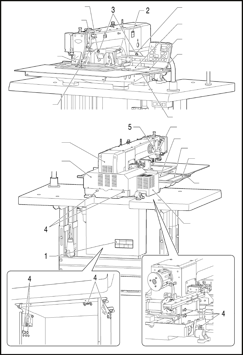
Carry out the procedures indicated by [1] to [15] in the titles in the order of the numbers.
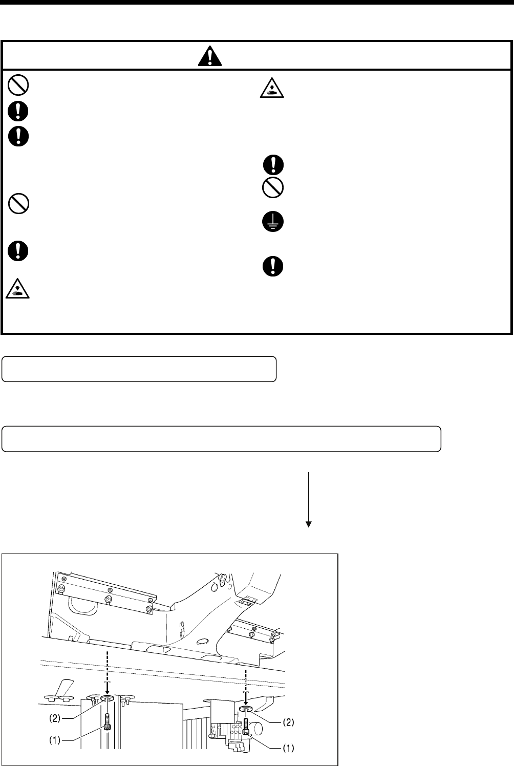
4-1. Removing the machine head fixing bolts [1]
If the sewing machine was already
installed to the table when it was
delivered, remove the two machine head
fixing bolts (1) and the two plain washers
(2).
2742B
4. INSTALLATION
5 BAS-342G PS
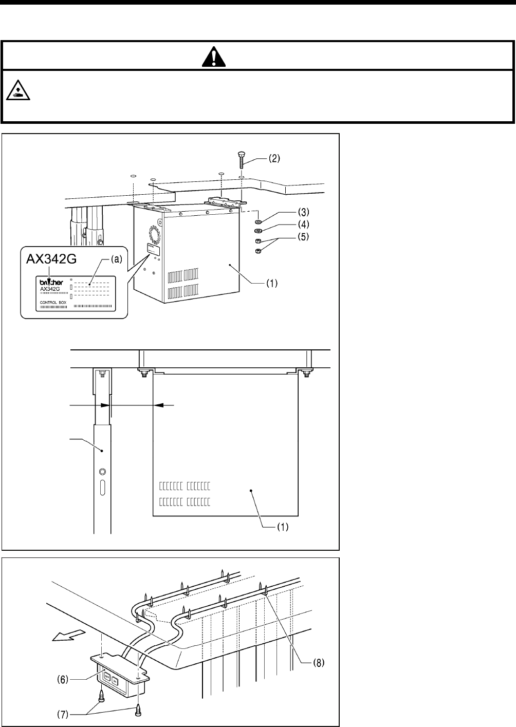
4-2. Installing the control box [2]
CAUTION
The control box is heavy, so installation should be carried out by two or more people.
In addition, take steps to make sure that the control box does not fall down.
If this is not done, injury to feet or damage to the control box may result.
Before installing the control box (1), check
that the model plate (a) on the control box
(1) is “AX342G” to indicate that it is an
RX-control box for BAS-342G sewing
machines.
* If the sewing machine is installed to the
table, tilt back the machine head.
(Refer to "4-5. Tilting back and returning
the machine head".)
(1) Control box
(2) Bolts [4 pcs.]
(3) Plain washers [4 pcs.]
(4) Spring washers [4 pcs.]
(5) Nuts [8 pcs.]
NOTE:
Check that the control box (1) is at
least 10 mm away from the leg. If the
control box (1) and the leg are too
close together, it may result in
incorrect sewing machine operation.
(6) Power switch
(7) Wood screws [2 pcs.]
(8) Staples [7 pcs.]
NOTE:
Take care when tapping in the staples
(8) to make sure that they do not
pierce the power cord.
3962M
3961
M
10mm or more
Leg
Operator
3963M
4. INSTALLATION
6
BAS-342G PS
4-3. Installing the oil pan and support lever base
(1) Oil pan
(2) Wood screws [4 pcs.]
(3) Oiler
(4) Support lever base
(5) Plain washers [2 pcs.]
(6) Spring washers [2 pcs.]
(7) Bolts [2 pcs.]
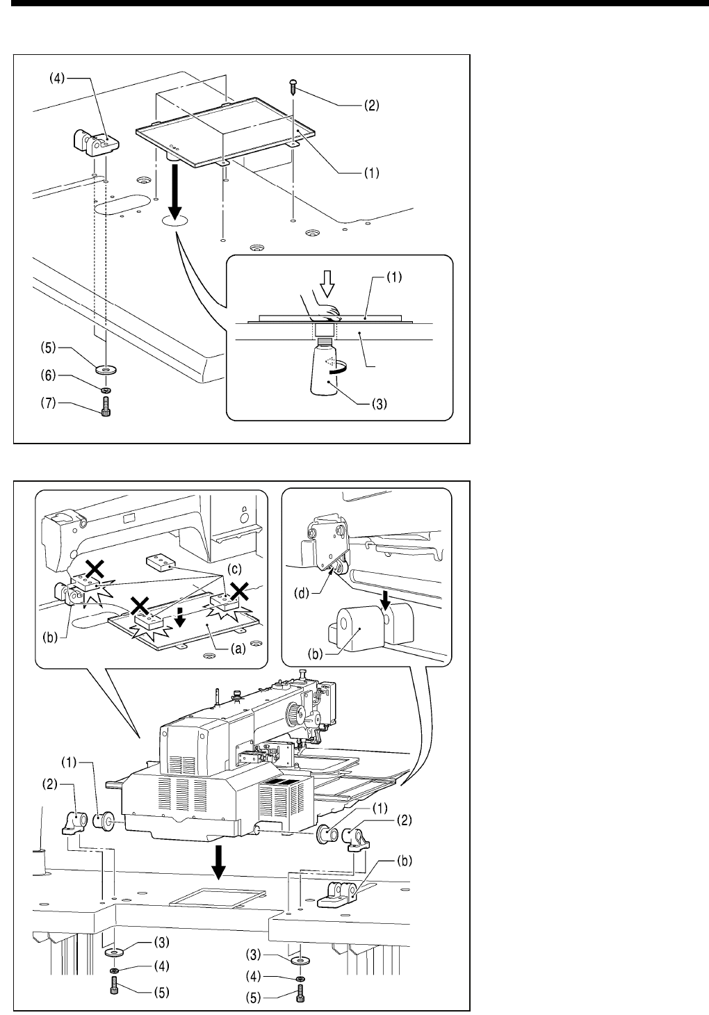
4-4. Installing the machine head
1. Place the machine head onto the
table.
NOTE:
• Use a crane or hoist to install the
sewing machine.
• Be careful of the following when
lowering the machine head onto the
table.
! Do not let any cords get clamped
between the machine head and
the table.
! Do not place the machine head
cushion (c) on top of the oil pan
(a) or the support lever base (b).
! Do not let the side (d) of the
safety switch lever touch the
support lever base (b).
(1) Rubber bushes (2 pcs.)
(2) Hinge holders (2 pcs.)
(3) Plain washers [4 pcs.]
(4) Spring washers [4 pcs.]
(5) Bolts [4 pcs.]
(Continued on next page)
2743
B
3964M
Table
4. INSTALLATION
7 BAS-342G PS
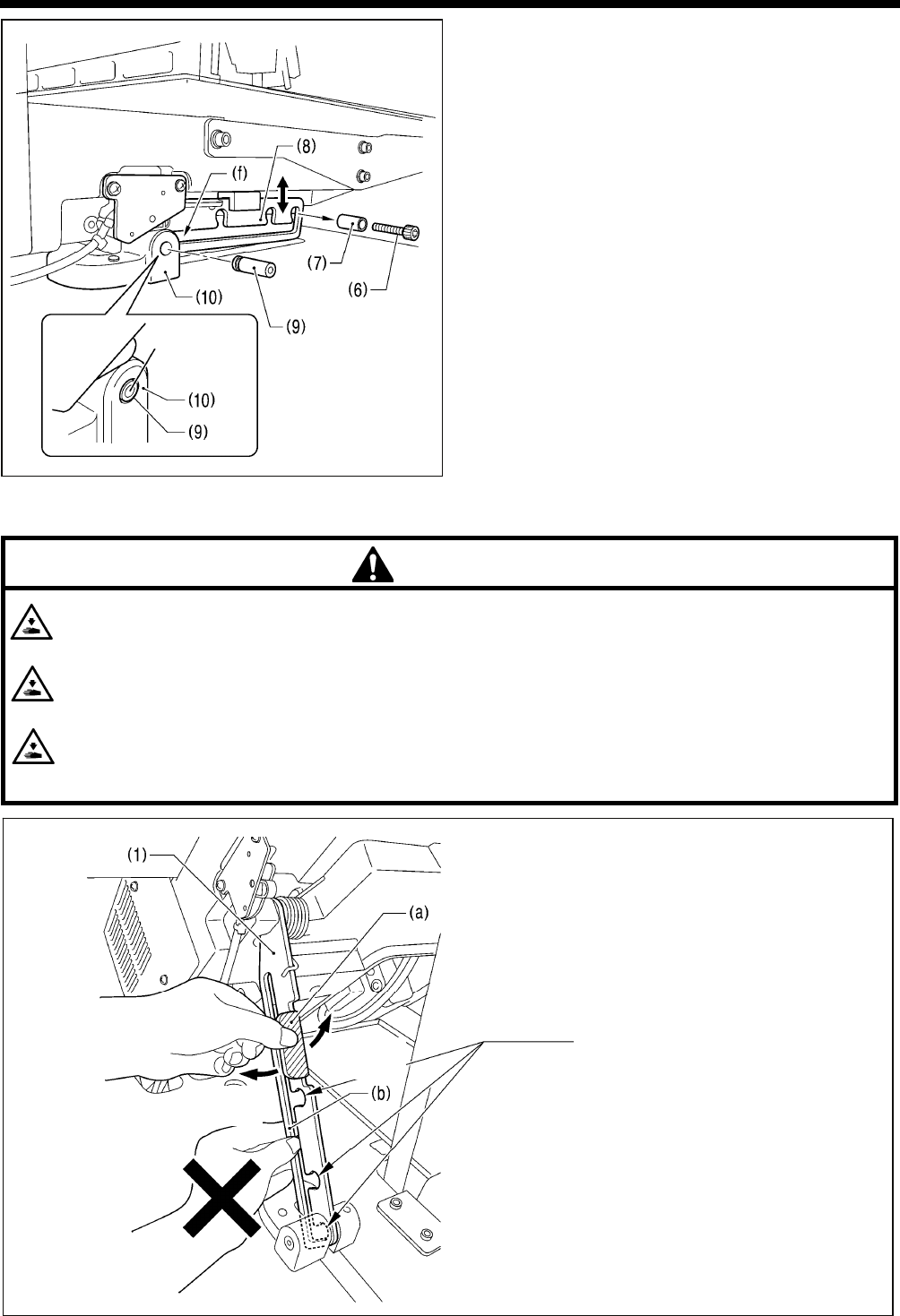
2. After placing the machine head onto the table, remove the
bolt (6) and the spacer (7).
* The bolt (6) and the spacer (7) are necessary for
securing the support lever (8) when the machine head is
removed from the table, so keep them in a safe place.
3. Pass the support lever shaft (9) through the hole in the
support lever base (10) and through the groove (f) in the
support lever (8), and push it in until it is flush with the
surface of the support lever base (10).
* If it is difficult to pass the support lever shaft (9) through
the groove (f) in the support lever (8), move the end of
the support lever (8) up and down while passing the
support lever shaft (9) through.
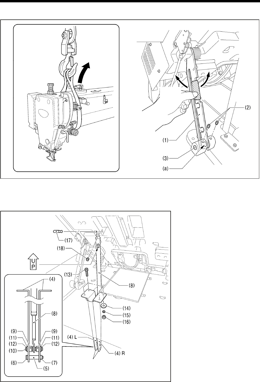
4-5. Tilting back and returning the machine head
CAUTION
Hold the machine head with both hands when tilting it back or returning it to its original position.
In addition, do not subject the machine head to extra force while it is tilted back. If this is not observed, the machine head
may become unbalanced and fall down, and serious injury or damage to the sewing machine may result.
Always be sure to engage the stopper of the support lever (1) when tilting back the machine head.
If the stopper is not engaged, the machine head may return to its original position and your hands may get caught and
injury may result.
When disengaging the stopper, hold it by the knob (a).
If you hold at the place indicated by (b), your hand will get caught between the support lever (1) and the table when the
machine head is returned to its original position and injury will result.
The machine head can be tilted
back and returned to one of three
heights.
3966
M
Flush
3967M
Disengaging
the stopper
Engaging
the stopper
4. INSTALLATION
8
BAS-342G PS
4-6. Installing the gas spring
1. Tilt back the machine head, and then secure the support lever (1) at stopper position (a).
(Refer to "4-5. Tilting back and returning the machine head".)
NOTE: Use equipment such as a crane or hoist to tilt back the machine head.
2. Tighten the two set screws (2) to secure the support lever shaft (3).
3. Install the gas spring (8).
(4) Gas spring holders [L and R]
(5) Spacer
(6) Bolt
(7) Nut
(8) Gas spring
(9) Shaft collars [2 pcs.]
(10) Gas spring shaft D
(11) Plain washers [2 pcs.]
(12) Retaining rings E [2 pcs.]
(13) Bolts [4 pcs.]
(14) Plain washers [4 pcs.]
(15) Spring washers [4 pcs.]
(16) Nuts [4 pcs.]
(17) Gas spring shaft U
(18) Set screw
* After installing the gas spring (8), gently
return the machine head to its original
position.
(Refer to "4-5. Tilting back and
returning the machine head".)
2744B
Disengaging
the stopper
Engaging
the stopper
Crane or hoist
2915B
Note that the L and R
shapes are different.
Be sure to install so that
the side with “UP” on it is
facing upward.
4. INSTALLATION
9 BAS-342G PS
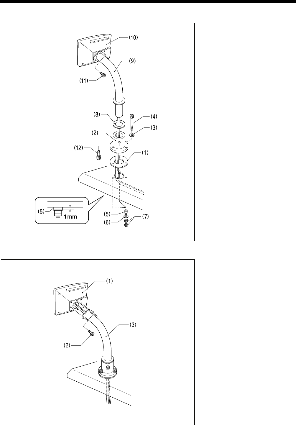
4-7. Installing the operation panel [3]
(1) Cushion A
(2) Operation panel base
(3) Plain washers (medium) [3 pcs.]
(4) Bolts [3 pcs.]
(5) Cushions B [3 pcs.]
(6) Plain washers (large) [3 pcs.]
(7) Nuts [6 pcs.]
* Tighten until the thickness of
cushion B (5) is about 1 mm.
(8) Rubber seat
(9) Operation panel stand
(10) Operation panel
* Pass the cords of the operation
panel (10) through the operation
panel stand (9) and under the
table.
(11) Bolts [3 pcs.]
(12) Bolt
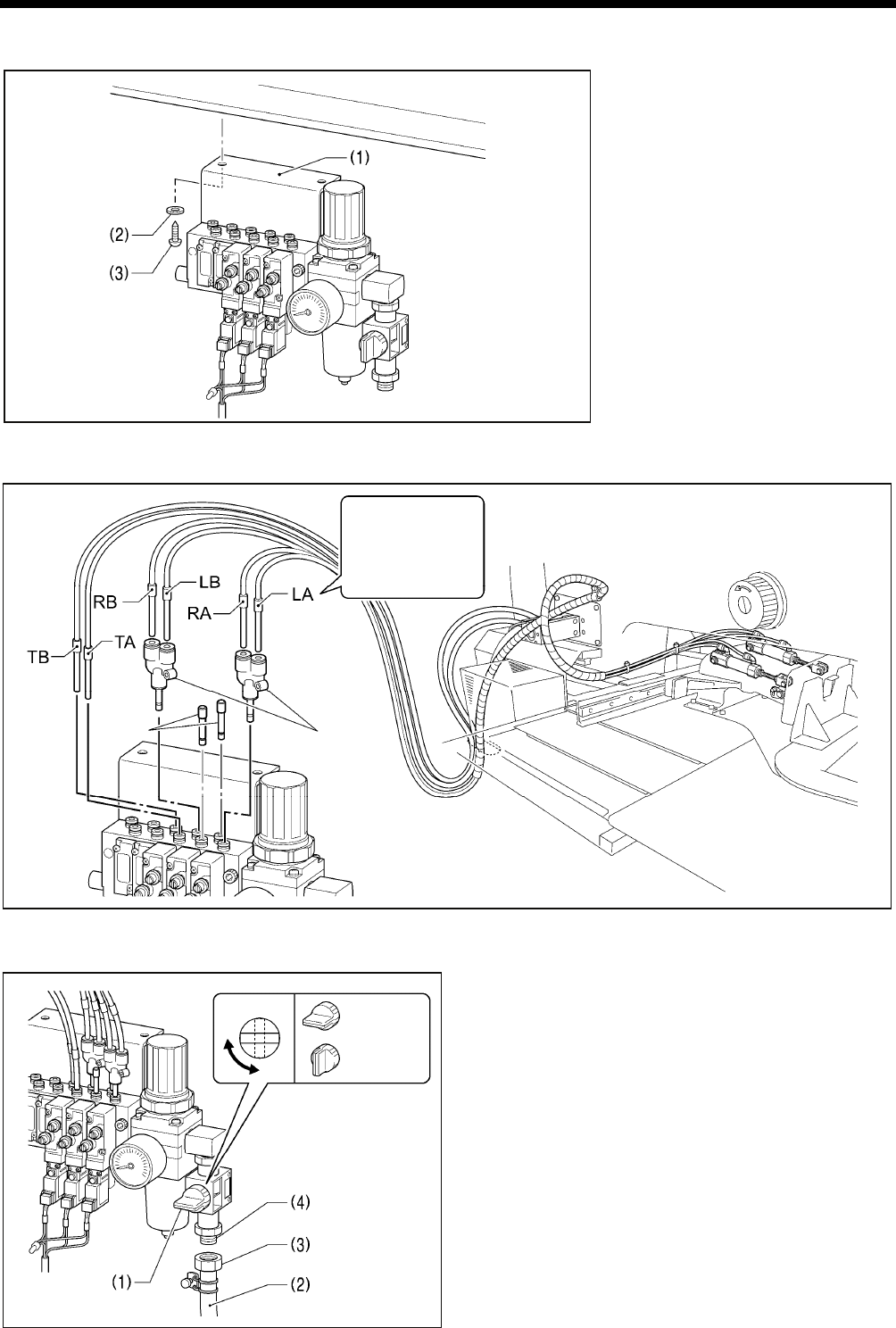
< If the sewing machine was already installed to the table when it was delivered >
(1) Operation panel
(2) Bolts [3 pcs.]
* Pass the cords of the operation
panel (1) through the operation
panel stand (3) and under the
table.
3970
M
3971M
4. INSTALLATION
10
BAS-342G PS
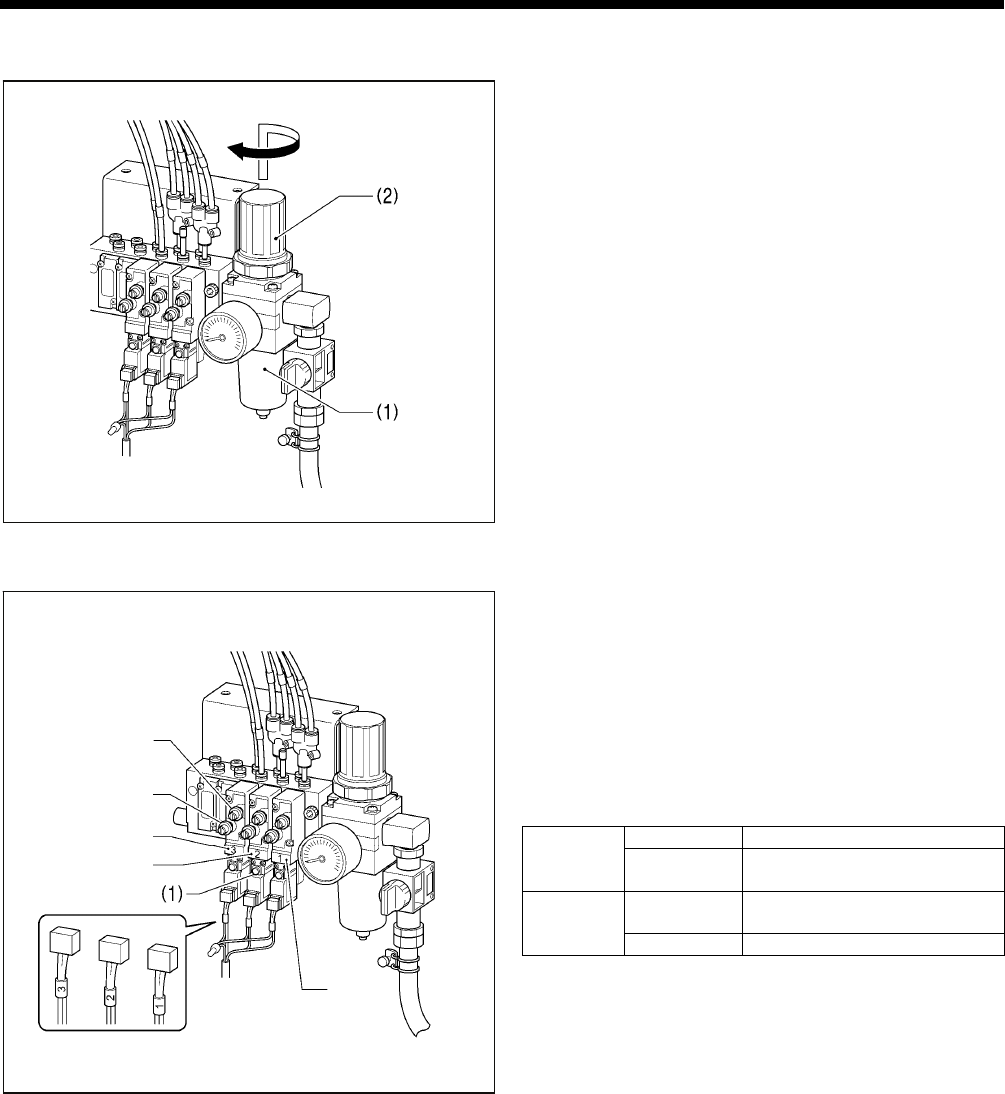
4-8. Installing the solenoid valve assembly
Install underneath the work table. (Refer
to "3. Table processing diagram" for the
installation positions.)
(1) Solenoid valve assembly
(2) Washers [2 pcs.]
(3) Wood screws [2 pcs.]
NOTE:
Make sure that the solenoid valve
assembly does not touch the control
box or the leg of the table.
4-9. Connecting the air tubes [4]
4-10. Installing the air hose [5]
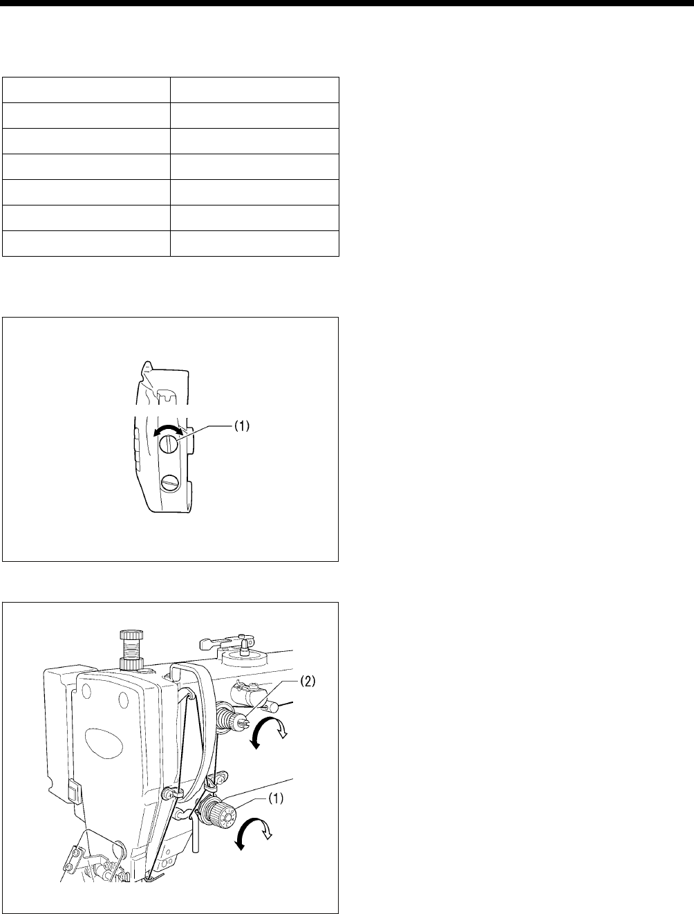
1. Close the cock (1).
2. Turn the nut (3) at the end of the air hose (2) and connect it
to the valve (4).
3. Open the cock at the compressor.
* Check that no air is leaking from the connection of the
valve (4) and air hose (2).
4. Open the cock (1).
(The meter pointer will turn clockwise.)
NOTE:
Turn the cock (1) gently to open it.
5. Adjust the air pressure. (Refer to the next page.)
2745B
2746B
Branch unions Y
Plugs 4
Connect as shown in
the illustration while
checking the marks.
2747
B
Open
Close
4. INSTALLATION
11 BAS-342G PS
4-11. Adjusting the air pressure [6]
Lift up the handle (2) of the regulator (1) and then turn it to
adjust the air pressure to 0.5 MPa.
After adjustment is complete, push the handle (2) downward to
lock it.
4-12. Adjusting the speed controller [7]
< Adjusting the lifting and lowering speeds for the work
clamp >
You can adjust the lifting and lowering speeds for the work
clamp using the knobs on valves 1 and 2.
• When the upper knob is tightened, the lifting speed becomes
slower. When it is loosened, the lifting speed becomes faster.
• When the lower knob is tightened, the lowering speed
becomes slower. When it is loosened, the lowering speed
becomes faster.
Reference adjustments
Upper knob Fully tighten
Valve 1 Lower knob Fully tighten and then loosen by
8 turns
Upper knob Fully tighten and then loosen by
5 turns
Valve 2
Lower knob Fully tighten
You can operate the work clamp when the power is turned off
by pressing the manual buttons (1).
< Adjusting the speed of the thread trimming air cylinder >
Valve 3 is used for adjusting the speed of the thread trimming
air cylinder. To use, fully tighten both the upper and lower knobs,
and then loosen them both by 6 turns.
* If the knobs are not at the tightening settings mentioned
above, upper thread trimming may not work correctly.
2749
B
Valve 2
Upper knob
Lower knob
Valve 1
Valve 3
2748
B
4. INSTALLATION
12
BAS-342G PS
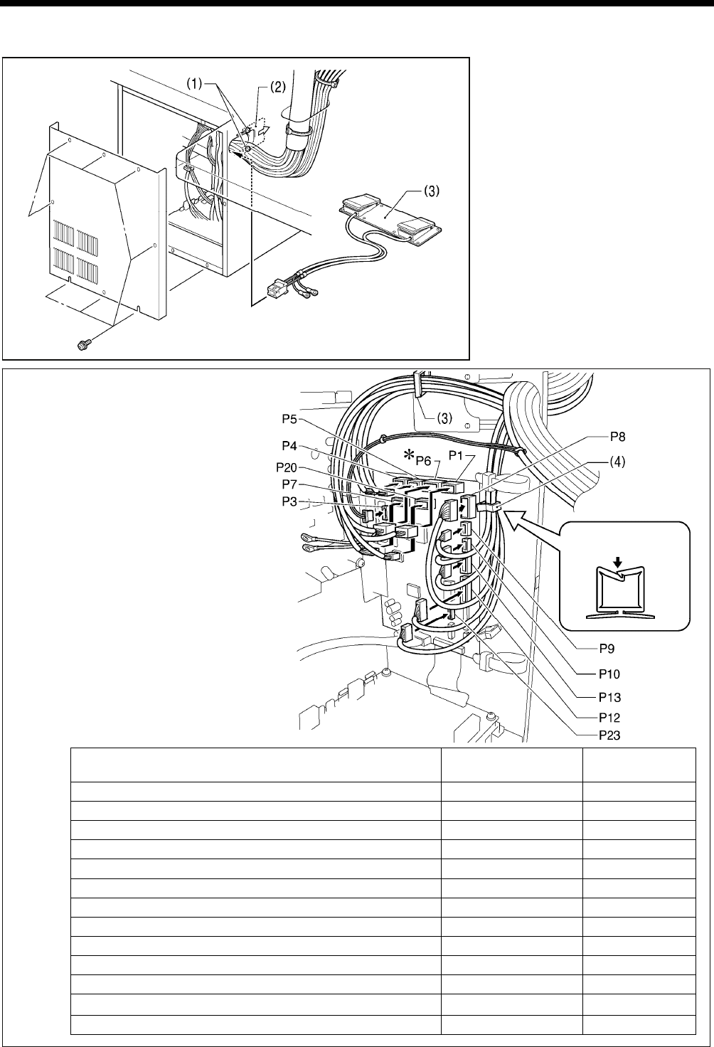
4-13. Connecting the cords [8]
1. Remove the cover of the control box.
2. Loosen the two screws (1), and then
open the cord presser plate (2) in the
direction of the arrow.
3. Pass the bundle of cords from the
machine head through the hole in the
table, and then pass it through the
hole in the control box together with
the following cords.
• Tow-pedal foot switch (3)
• Operation panel (Do not pass the
ground wires through the hole.)
• Solenoid valve assembly
4. Securely connect the connectors as
indicated in the table below.
<Main P.C. board>
NOTE:
• Check that the connector is facing the
correct way, and then insert it firmly
until it locks into place.
• Secure the cables with cable ties and
cord clamps, while being careful not to
pull on the connector.
* Be sure to make the ground connection.
(Refer to "4-14. Connecting the ground
wire".)
Connector Connection location on
main P.C. board Cord clamp
X pulse motor encoder 5-pin white P20 (X-ENC) (3)
Y pulse motor encoder 5-pin blue P4 (Y-ENC) (3)
Intermittent presser foot pulse motor encoder 5-pin black P5 (P-ENC) (3)
Foot switch 10-pin P6 (FOOT) (3)
Operation panel 8-pin P1 (PANEL) (3)
Safety switch 3-pin P9 (HEAD-SW) (4)
Home position sensor assembly 12-pin P8 (SENSOR1) (4)
STOP switch 6-pin P13 (HEAD) (4)
Valve harness 12-pin P12 (AIR1) (4)
Programmer relay harness 8-pin P7 (PRG) (3)
Fan 6-pin P10 (SENSOR2) (4)
Solenoid selection harness 4-pin P3 (CUTTER) -
Thread trimming cylinder sensor harness 16-pin P23 (EX-IN1) (4)
(Continued on next page)
Lock the cord
clamp securely.
3977
M
2916B
4. INSTALLATION
13 BAS-342G PS
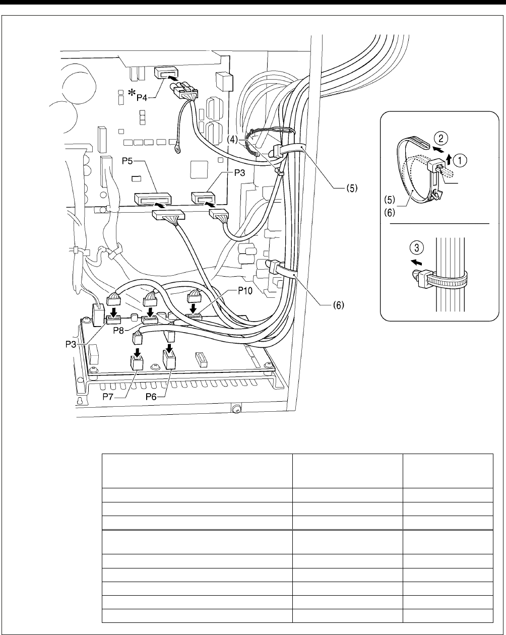
<Power supply motor P.C. board>
<PMD P.C. board>
Connector
Connection location on
power supply motor P.C.
board
Cord clamp/cable tie
Machine head memory 7-pin P3 (HEAD-M) (4)
Upper shaft motor 3-pin P4 (UVW) (5)
Synchronizer 14-pin P5 (SYNC) (5), (6)
Connector Connection location on
PMD P.C. board Cable tie
Work clamp pulse motor 4-pin black P3 (PPM) (5), (6)
Thread trimmer solenoid 6-pin P6 (SOL1) (5), (6)
Tension release solenoid 4-pin P7 (SOL2) (5), (6)
Y pulse motor 4-pin blue P8 (YPM) (5), (6)
X pulse motor 4-pin white P10 (XPM) (5), (6)
<Removing>
Press
the tab.
<Securing>
2568B
NOTE:
Route the X, Y and work clamp pulse moto
r
harnesses so that they do not touch the
PMD P.C.
* Be sure to make the ground connection.
(Refer to "4-14. Connecting the ground
wire".)
4. INSTALLATION
14
BAS-342G PS
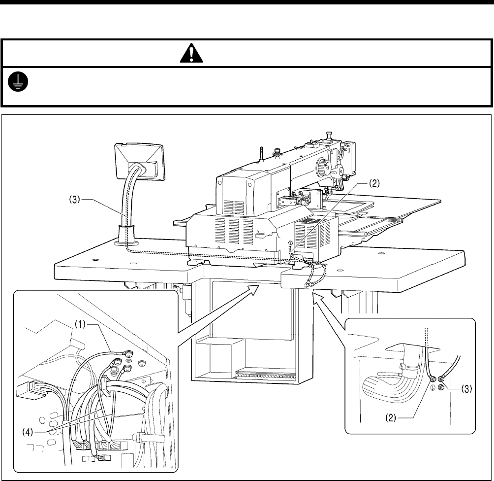
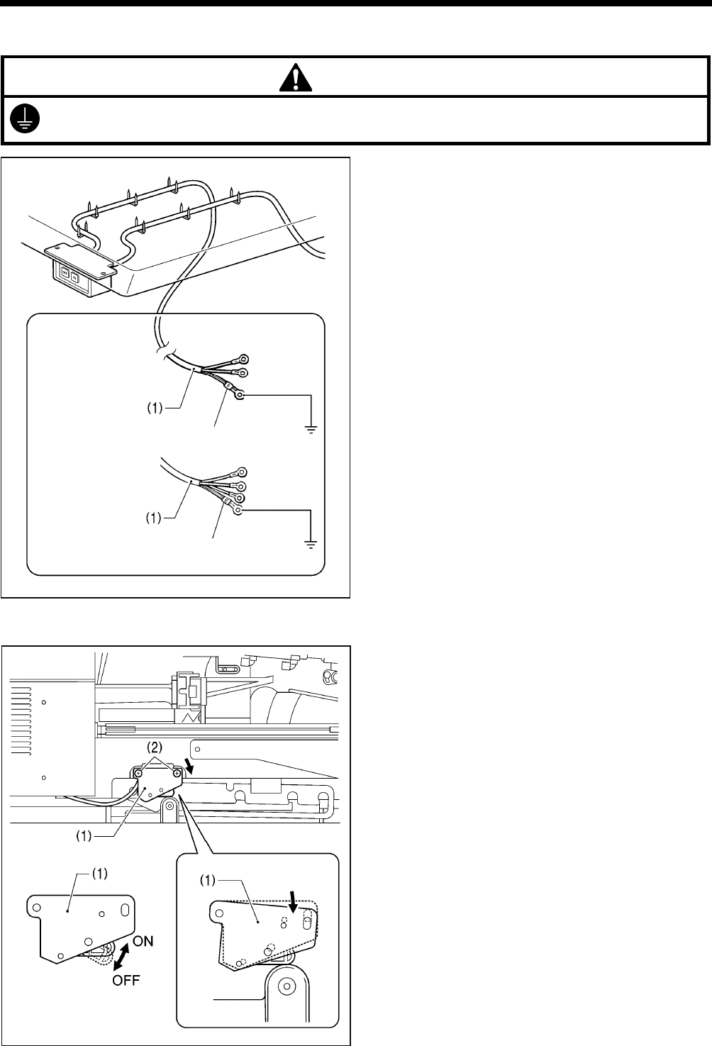
4-14. Connecting the ground wire [9]
CAUTION
Be sure to connect the ground. If the ground connection is not secure, you run a high risk of receiving a serious electric
shock, and problems with correct operation may also occur.
(1) Ground wire from upper shaft motor harness
(2) Ground wire from the machine head
(3) Ground wire from operation panel
(4) Ground wires from two-pedal foot switch harnesses (2 wires)
NOTE: Make sure that the ground connections are secure in order to ensure safety.
2750
B
4. INSTALLATION
15 BAS-342G PS
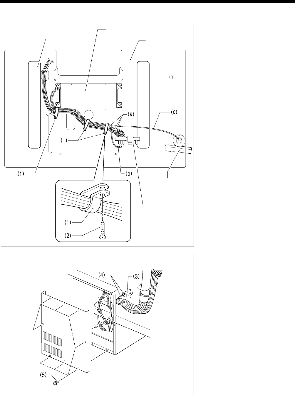
4-15. Securing the cords and air tubes [10]
Secure the three air tubes (a), the
solenoid valve assembly cord (b) and the
operation panel cord (c) together
underneath the table with the three cord
holders (1).
(1) Cord holders [3 pcs.]
(2) Wood screws [3 pcs.]
<Checking the cords>
1. Gently tilt back the machine head.
(Refer to "4-5. Tilting back and
returning the machine head".)
2. Check that none of the cords are
being pulled.
3. Return the machine head to its
original position.
4. Close the cord presser plate (3) in the
direction of the arrow, and secure it by
tightening the two screws (4).
NOTE:
Close the cord presser plate (3)
securely so that no foreign objects,
insects or small animals can get
inside the control box.
5. Secure the cover of the control box by
tightening the eight screws (5).
Check that the cords are not clamped
by the cover at this time.
3982M
<Seen from underneath table> Control box
Table
2751B
Operation panel
Solenoid valve
assembly
Leg
4. INSTALLATION
16
BAS-342G PS
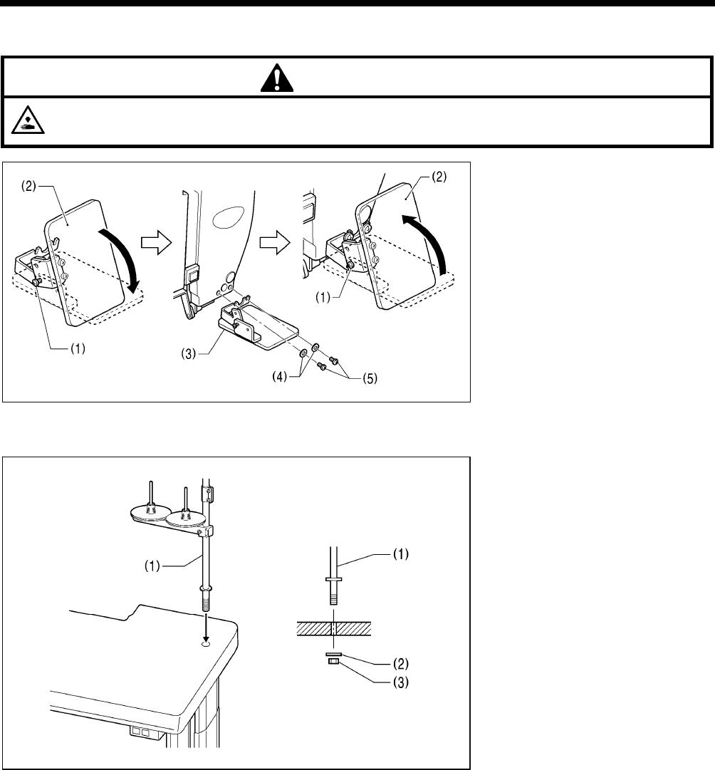
4-16. Installing the eye guard [11]
CAUTION
Attach all safety devices before using the sewing machine.
If the machine is used without these devices attached, injury may result.
(1) Screw (loosen)
(2) Eye guard (tilt forward)
(3) Eye guard assembly
(4) Plain washers [2 pcs.]
(5) Screws [2 pcs.]
After installing the eye guard assembly
(3), return the eye guard (2) to its original
angle, and then tighten the screw (1) to
secure it in place.
4-17. Installing the cotton stand [12]
(1) Cotton stand
NOTE:
Fit the washer (2), and then securely
tighten the nut (3) so that the cotton
stand does not move.
3983
M
2367B
4. INSTALLATION
17 BAS-342G PS
4-18. Lubrication [13]
CAUTION
Do not connect the power cord until lubrication is complete.
If the foot switch is depressed by mistake, the sewing machine might start operating and injury could result.
Be sure to wear protective goggles and gloves when handling the lubricating oil and grease, so that they do not get into
your eyes or onto your skin. If the oil and grease get into your eyes or onto your skin, inflammation can result.
Furthermore, do not drink or eat the lubricating oil or grease. They may cause diarrhea or vomiting.
Keep the oil out of the reach of children.
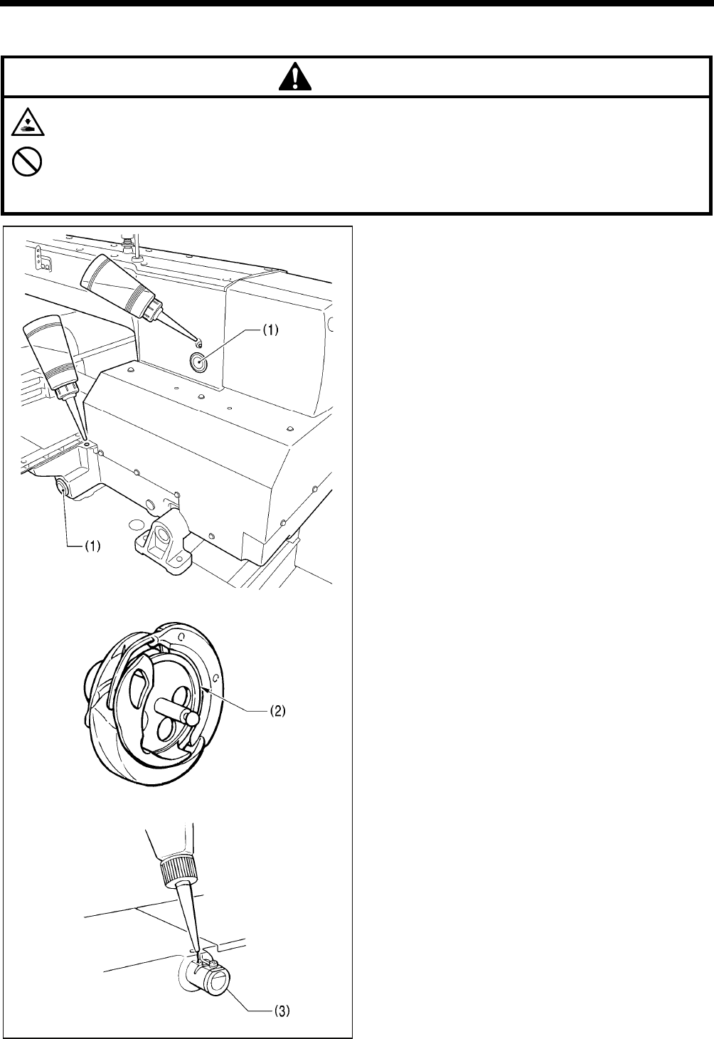
• The sewing machine should always be lubricated and the oil
supply replenished before it is used for the first time, and
also after long periods of non-use.
• Use only the lubricating oil <JX Nippon Oil & Energy
Corporation Sewing Lube 10N; VG10> specified by Brother.
* If this type of lubricating oil is difficult to obtain, the recommended
oil to use is <Exxon Mobil Essotex SM10; VG10>.
1. Fill the arm oil tank and the bed oil tank with oil.
NOTE:
Be sure to add more oil when the oil level drops down
to about one-third full in the oil gauge window (1). If the
oil drops below the one-third full level in the oil gauge
window (1), there is the danger that the sewing
machine may seize during operation.
2. Remove the bobbin case and add 2-3 drops of oil to the
rotary hook race (2).
3. If using the needle cooler (3), fill it with silicon oil (100
mm2/s).
(Refer to "5-3. Threading the upper thread" for details on
using the needle cooler (3).)
2752B
2753B
3986M
4. INSTALLATION
18
BAS-342G PS
4-19. Connecting the power cord [14]
CAUTION
Be sure to connect the ground. If the ground connection is not secure, you run a high risk of receiving a serious electric
shock, and problems with correct operation may also occur.
1. Attach an appropriate plug to the power cord (1). (The
green and yellow wire is the ground wire.)
2. Insert the plug into a properly-grounded AC power supply.
* The inside of the control box uses single-phase power.
NOTE:
• If the ground connection is not secure, electric shocks,
operating errors or damage to electronic components
such as P.C. boards may occur.
• Do not use an extension cord. If this is not observed, it
may cause problems with correct operation.
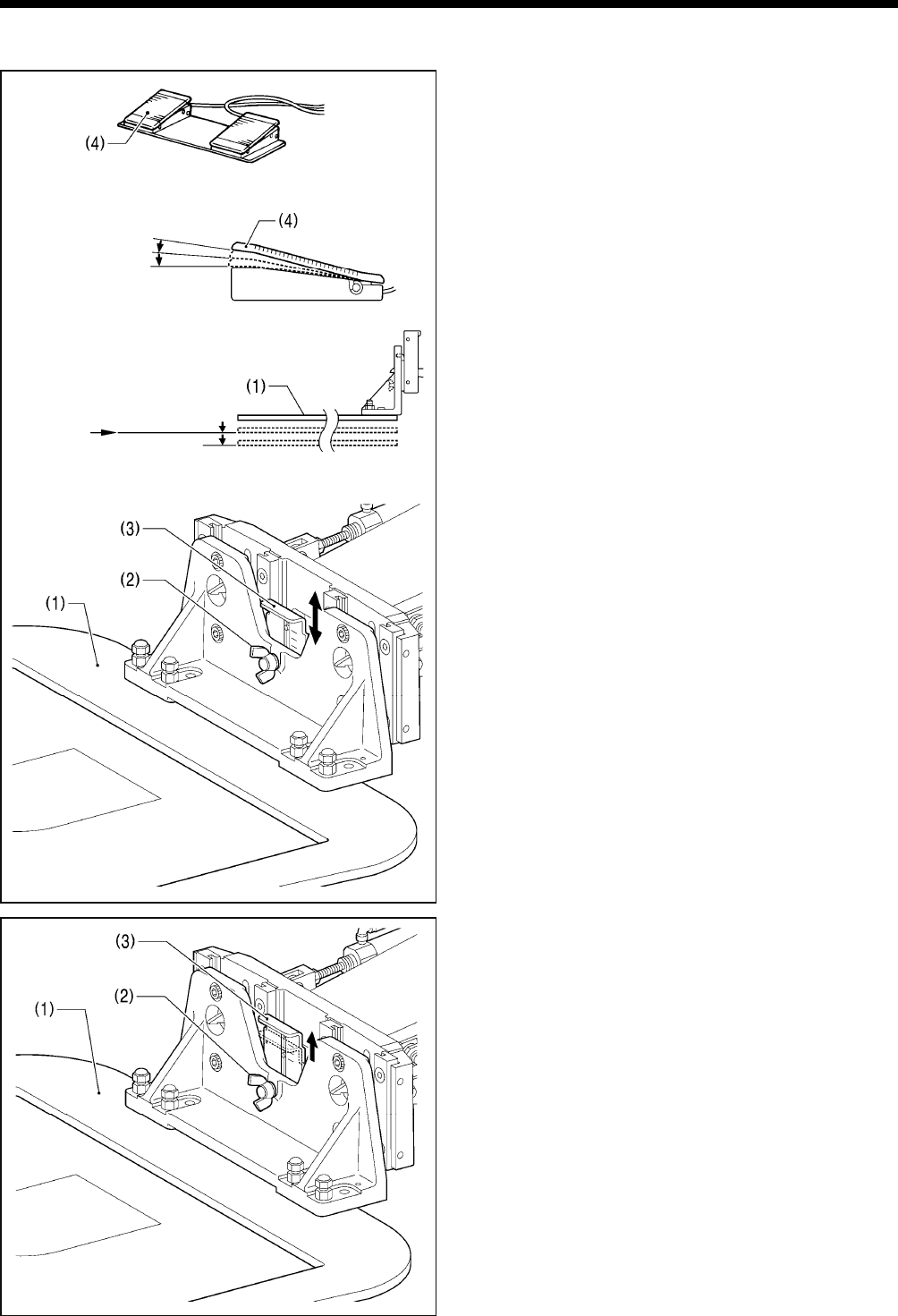
4-20. Checking the safety switch [15]
1. If the machine head is tilted back, gently return it to its
original position. (Refer to "4-5. Tilting back and returning
the machine head".)
2. Turn on the power switch.
3. Check that no error numbers are displayed on the operation
panel.
<If error [E050], [E051] or [E055] is displayed >
If the safety switch (1) is not turned on, error [E050], [E051] or
[E055] will occur.
Check the installation position of the safety switch (1).
1. Turn off the power switch.
2. Loosen the two screws (2).
3. Push down the right side of the safety switch (1) so that the
safety switch (1) turns on, and then tighten the two screws
(2).
4. Turn on the power and check that no error numbers are
displayed.
<Single-phase
specifications>
3988M
Green and yellow wire
(ground wire)
<Three-phase
specifications>
Green and yellow wire
(ground wire)
3989M
5. PREPARATION BEFORE SEWING
19 BAS-342G PS
5. PREPARATION BEFORE SEWING
5-1. Installing the needle
CAUTION
Turn off the power switch before installing the needle.
If the foot switch is depressed by mistake, the sewing machine might start operating and injury could result.
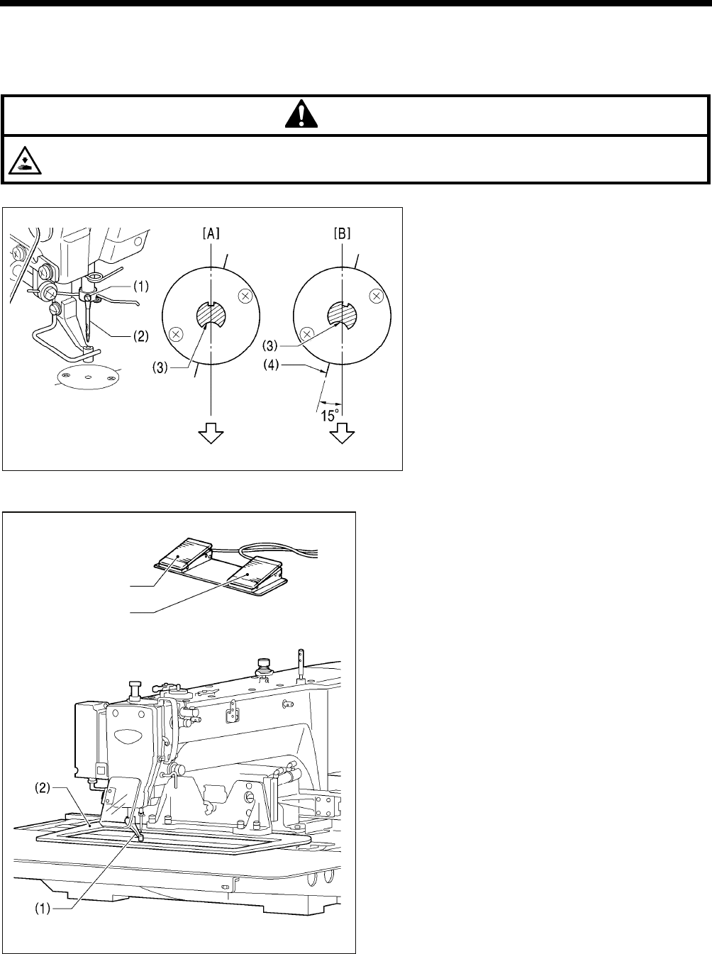
1. Loosen the set screw (1).
2. Insert the needle (2) as far as it will go with the
hollow (3) facing to the front, and then securely
tighten the set screw (1). [Figure A]
<If hitch stitches appear in one direction during
square sewing>
1. Loosen the set screw (1).
2. Insert the needle (2) as far as it will go so with
the hollow (3) facing to the front and so that it’s
angle matches the angle of reference line (4),
and then securely tighten the set screw (1).
[Figure B]
* If the installation angle of the needle has been
changed, be sure to readjust the needle
clearance. (Refer to “11-6. Adjusting the needle
clearance”.)
5-2. Operating the 2-pedal foot switch
When the work clamp switch (left side) is depressed, the
intermittent presser foot (1) and the work clamp (2) are
lowered, and when the start switch (right side) is then
depressed, the sewing machine starts operating.
* The work clamp (2) lowering method can be changed
using memory switch No. 002. (Refer to "7-3. List of
memory switch settings.")
Work clamp switch
Start switch
3991M
2755B
2754B Front Front
5. PREPARATION BEFORE SEWING
20
BAS-342G PS
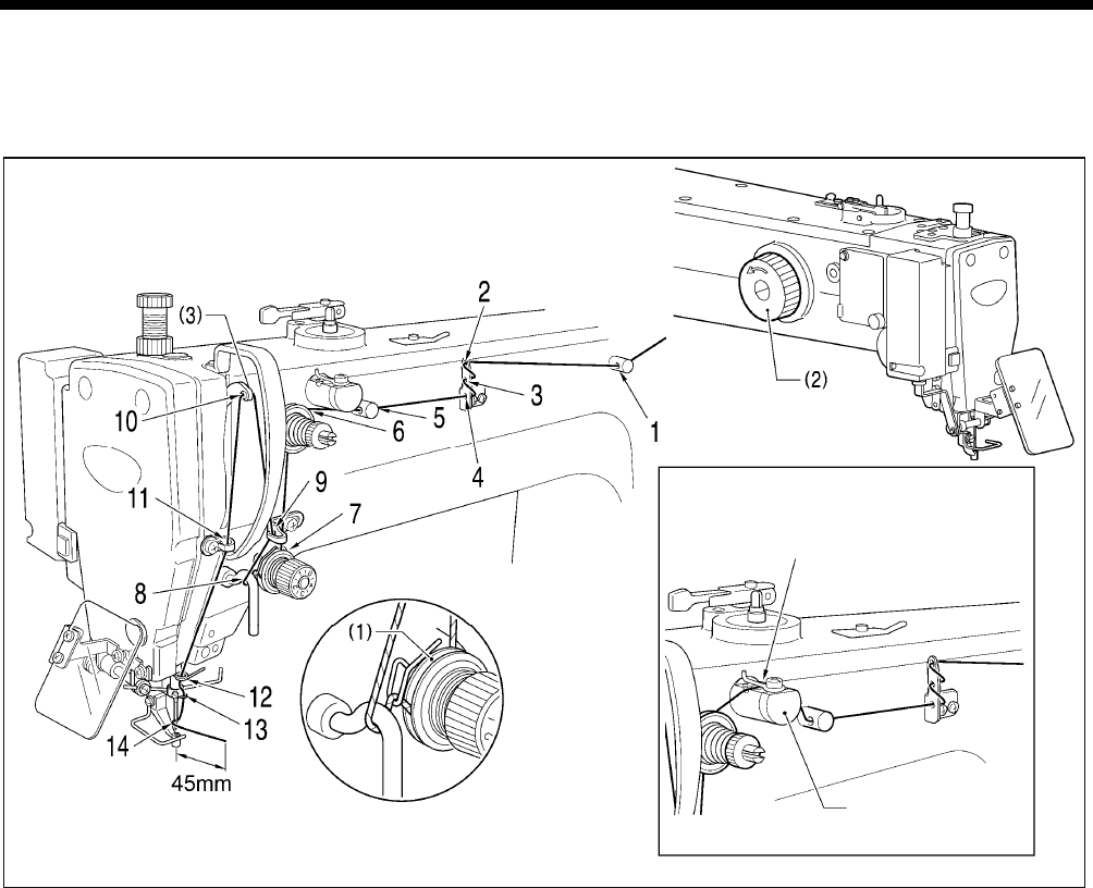
5-3. Threading the upper thread
Thread the upper thread correctly as shown in the illustration below.
* When using threading mode for threading, the tension discs (1) will open so that the thread can be threaded more easily.
(Refer to following page.)
• Turn the machine pulley (2) and raise the thread take-up (3) to its highest position before threading the upper thread.
(This will make threading easier and it will prevent the thread from coming out at the sewing start.)
• When threading the thread through the needle, allow a distance of approximately 45 mm between the needle hole and the
end of the thread.
If the trailing length of the thread is too long, it may cause the thread to become tangled.
[If using cotton thread or spun thread]
2756B
2572B
2757B
[If using synthetic thread]
Thread the upper thread
Needle cooler
5. PREPARATION BEFORE SEWING
21 BAS-342G PS
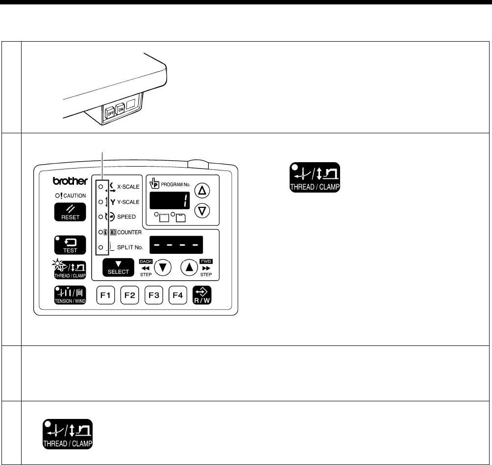
<Threading mode>
Threading mode is safe because the sewing machine will not start even when the foot switch is depressed.
1
Turn on the power switch.
2
THREAD/CLAMP indicator illuminates
MENU indicator switches off
Press the THREAD/CLAMP key.
• The work clamp and the intermittent presser foot will be
lowered.
• The tension discs will open.
3 Threading the thread.
• When 5 minutes have passed, the buzzer will sound and the tension discs will close.
* When memory switch No. 564 is set to "2", the buzzer will sound after one minute has elapsed, and the tension
discs will close.
4 Ending threading mode
THREAD/CLAMP indicator switches off
Press the THREAD/CLAMP key.
• The work clamp and the intermittent presser foot will
return to the position they were at before threading mode
began.
All indicators switch off
4427Q
4421Q
5. PREPARATION BEFORE SEWING
22
BAS-342G PS
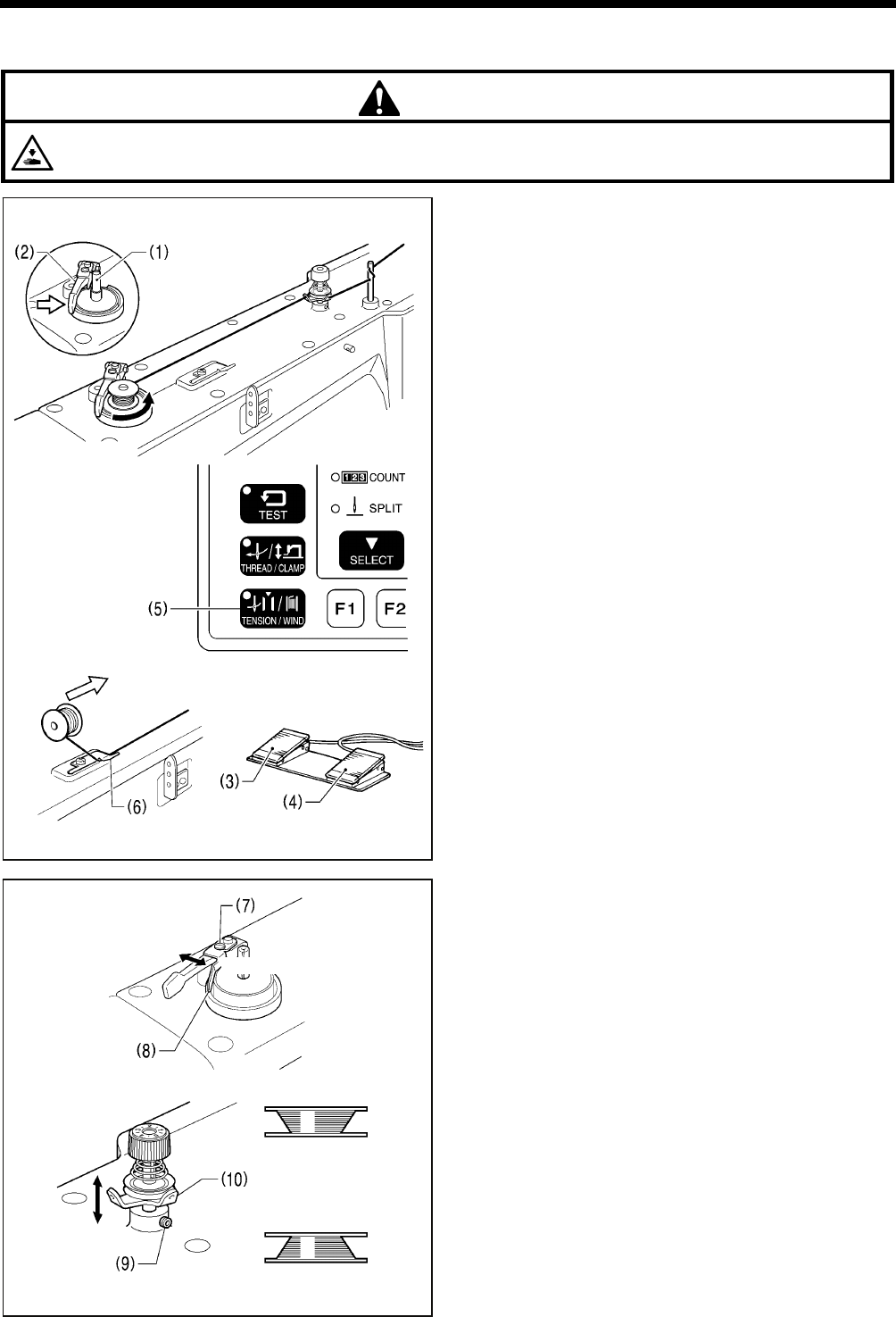
5-4. Winding the lower thread
CAUTION
Do not touch any of the moving parts or press any objects against the machine while winding the lower thread.
Injury or damage to the sewing machine may result.
1. Place the bobbin onto the bobbin winder shaft (1).
2. Thread the thread as shown in the illustration, wind the
thread around the bobbin several times, and then press
the bobbin presser arm (2).
3. Turn on the power switch.
4. Depress the work clamp switch (3) to lower the work
clamp, and then depress the start switch (4). (Home
position detection will be carried out.)
5. Check that the needle is not touching the work clamp.
6. Depress the work clamp switch (3) to lower the work
clamp.
7. While pressing the TENSION/WIND key (5), depress the
start switch (4).
8. Release the TENSION/WIND key (5) after the machine
starts operating, and keep depressing the start switch (4)
until the lower thread stops being wound onto the bobbin.
(If you release the start switch (4) while this operation is
in progress, hold down the TENSION/WIND key (5) and
then depress the start switch (4) to restart winding of the
thread.)
9. Once winding of the set amount of lower thread (80 - 90%
of the bobbin capacity) is completed, the bobbin presser
arm (2) will return automatically.
10. Remove the bobbin, hook the thread onto the knife (6),
and then pull the bobbin in the direction of the arrow to
cut the thread.
Adjusting the bobbin winding amount
Loosen the screw (7) and move the bobbin presser (8) to
adjust.
If the thread winds onto the bobbin unevenly
Loosen the set screw (9) and move the bobbin winder
tension assembly (10) up and down to adjust.
* For case A, move the bobbin winder tension assembly
(10) down, and for case B, move it upward.
2758B
More thread
Less thread
For case B
For case A
3997M
3999M
2759B
2760B
2775B
5. PREPARATION BEFORE SEWING
23 BAS-342G PS
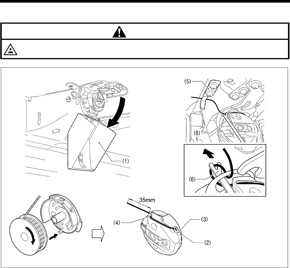
5-5. Installing the bobbin case
CAUTION
Turn off the power switch before installing the bobbin case.
If the foot switch is depressed by mistake, the sewing machine might start operating and injury could result.
1. Pull the hook cover (1) downward to open it.
2. While holding the bobbin so that the thread winds to the right, insert the bobbin into the bobbin case.
3. Pass the thread through the thread slot (2), pass it underneath the spring (3), and then pass it through the thread guide (4),
leaving a trailing-out length of about 35 mm.
4. Hold the latch on the bobbin case and insert the bobbin case into the rotary hook.
5. Clamp the lower thread in the thread hold spring (5).
6. Use the threading bar (6) to pass the thread through the window of the inner rotary hook. (The thread will be released from
the thread hold spring (5).)
2761B
1873B 1874B
1897B
5. PREPARATION BEFORE SEWING
24
BAS-342G PS
5-6. Thread tension
[Thread tension reference]
Upper thread #20 or similar
Lower thread #20 or similar
Upper thread tension (N) 1.0 − 1.6
Lower thread tension (N) 0.4 − 0.6
Pre-tension (N) 0.3 − 0.6
Needle DP x 17 #19
Normal sewing speed 2,000 sti/min
5-6-1. Lower thread tension
Adjust the lower thread tension by turning the adjusting
screw (1).
5-6-2. Upper thread tension
1. Turn the tension nut (1) (main tension) to adjust the
tension as appropriate for the material being sewn.
2. Use the tension nut (2) (sub tension) to adjust the upper
thread trailing length to about 45 mm.
2573B
Weaker
Stronger
Weaker
Stronger
Weake
r
1875B
Stronger
5. PREPARATION BEFORE SEWING
25 BAS-342G PS
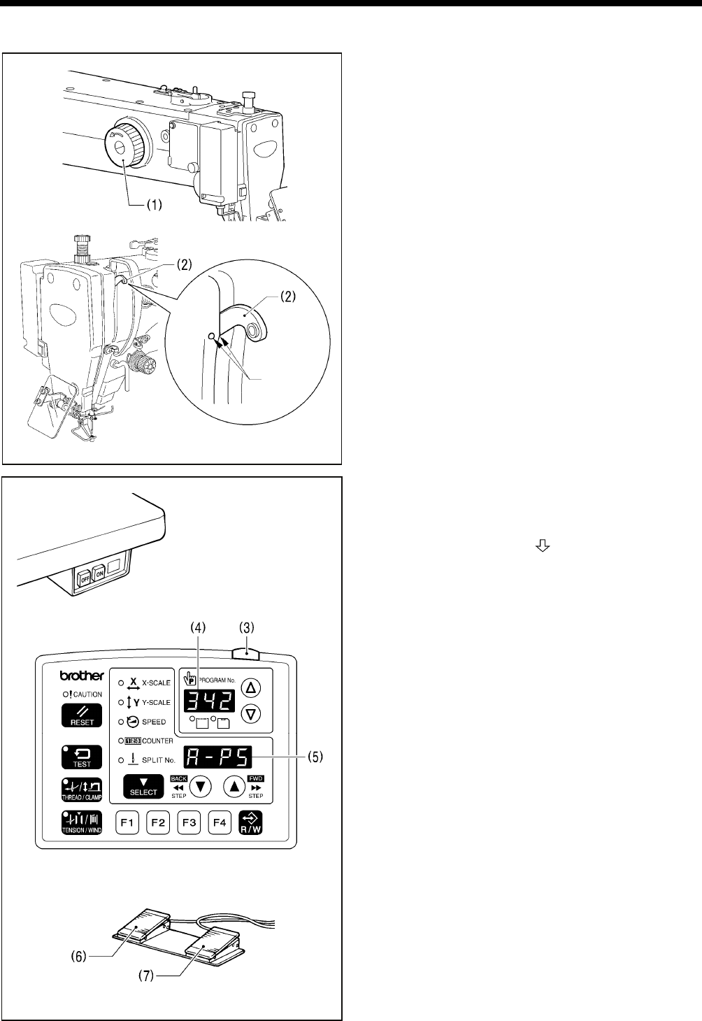
5-7. Home position detection
Before starting home position detection, check that the
needle bar is at the needle up stop position.
Turn the pulley (1) until the ridge at the bottom of the thread
take-up (2) is aligned with the { mark on the arm.
1. Turn on the power switch.
The POWER indicator (3) will illuminate, and the model
name [342] will appear in the PROGRAM No. display (4)
and [A-PS] will appear in the menu display (5).
After this, the program number will flash in the
PROGRAM No. display (4).
2. Depress the work clamp switch (6) to lower the work
clamp, and then depress the start switch (7). (After home
position detection is carried out, the work clamp will move
to the sewing start position and then it will rise.)
* For programs with a large number of stitches, the
buzzer will sound after the home position is detected,
and then the work clamp will move to the sewing start
position.
NOTE:
If error "E110" is displayed when the start switch (7) is
depressed, turn the pulley (1) in the direction of
operation to clear the error display.
4421Q
2574B
2918B
Aligned
4008M
4007M
2762B
5. PREPARATION BEFORE SEWING
26
BAS-342G PS
5-8. Setting 2-step operation for the work clamp
When these settings are made, the work clamp (1) can be
lowered in two steps.
1. Set memory switch No. 002 to "1".
(Refer to "7-2. Setting memory switches".)
2. With the work clamp (1) raised, loosen the wing screw
(2).
3. Move the work clamp stopper (3) up or down to determine
the intermediate position, and then tighten the wing screw
(2) to secure the work clamp stopper (3) in place.
4. Depress the work clamp switch (4) to the 1st step and
check the intermediate position for the work clamp.
5. Depress the work clamp switch (4) to the 2nd step to fully
lower the work clamp.
* 2-step work clamp operation is enabled when memory
switch No. 002 is set to "1".
* Do not set memory switch No. 002 to "2".
<To return the work clamp to one-step operation>
1. Set memory switch No. 002 to "0".
(Refer to "7-2. Setting memory switches".)
2. With the work clamp (1) raised, loosen the wing screw (2).
3. Move the work clamp stopper (3) to its highest position,
and then tighten the wing screw (2) to secure the work
clamp stopper (3) in place.
1st step
2nd step
1st step
2nd step
Intermediate
position
4009M
4010M
4011M
6. USING THE OPERATION PANEL (BASIC OPERATIONS)
27 BAS-342G PS
6. USING THE OPERATION PANEL
(BASIC OPERATIONS)
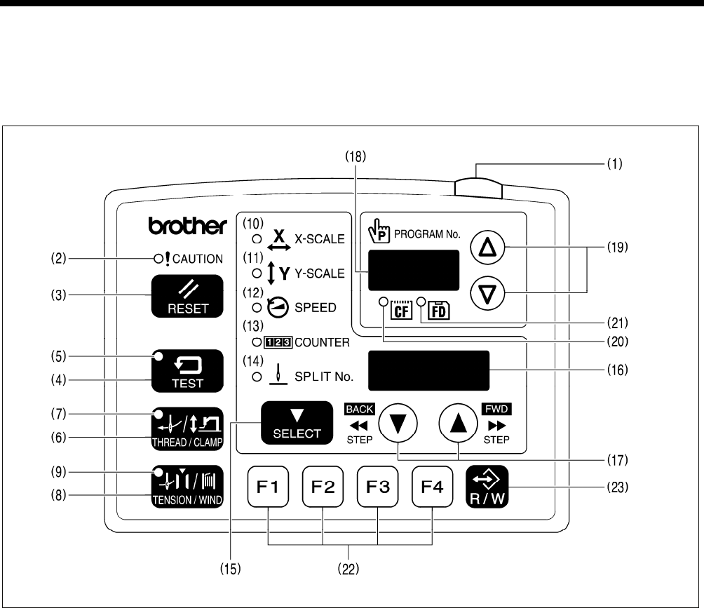
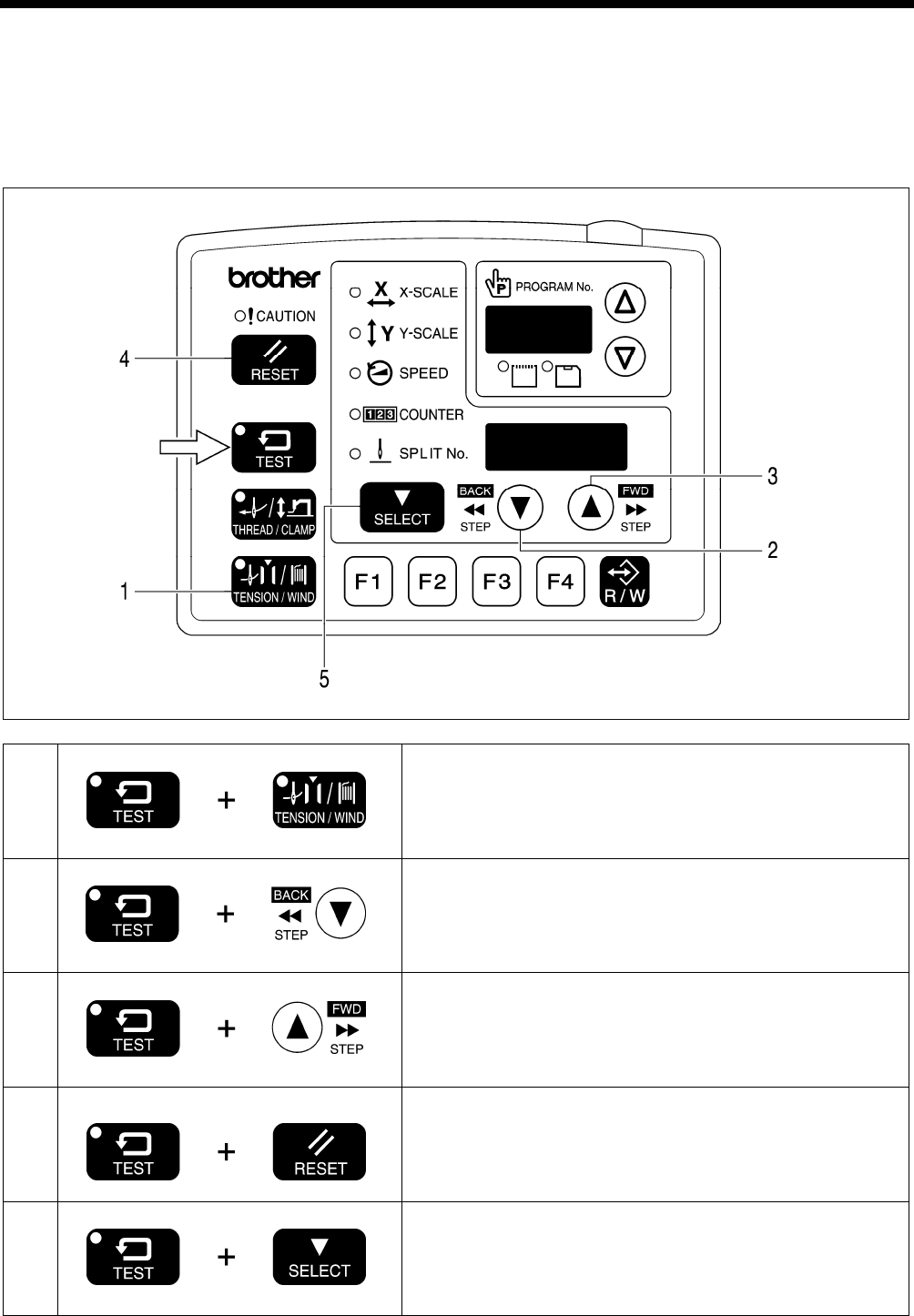
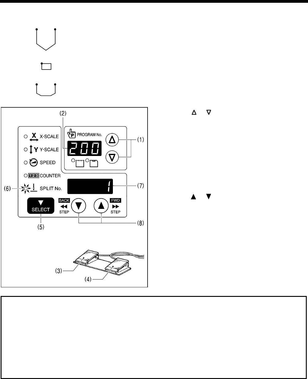
6-1. Name and function of each operation panel item
(1) Power indicator
Illuminates when the power is turned on.
(2) CAUTION indicator
Illuminates when an error occurs.
(3) RESET key
Used to reset errors.
(4) TEST key
Used to start test mode.
(5) TEST indicator
Illuminates when the TEST key (4) has been pressed.
(6) THREAD/CLAMP key
Used to start threading mode or work clamp height setting mode.
(7) THREAD/CLAMP indicator
Illuminates when the THREAD/CLAMP key (6) has been pressed.
(8) TENSION/WIND key
Used to wind the lower thread.
(9) TENSION/WIND indicator
Used when the digital tension set (option) is installed.
4435Q

6. USING THE OPERATION PANEL (BASIC OPERATIONS)
BAS-342G PS 28
(10) X-SCALE indicator
Illuminates when the SELECT key (15) is pressed to shown the X-scale setting.
(11) Y-SCALE indicator
Illuminates when the SELECT key (15) is pressed to shown the Y-scale setting.
(12) SPEED indicator
Illuminates when the SELECT key (15) is pressed to shown the sewing speed setting.
(13) COUNTER indicator
Illuminates when the SELECT key (15) is pressed to shown the lower thread or production counter setting.
(14) SPLIT No. indicator
Illuminates when the SELECT key (15) is pressed to show the split setting when split data (for specifying a pause while
the program is running) exists.
(15) SELECT key
Used to select a menu (X-scale, Y-scale, sewing speed and counter).
(16) Menu display
Displays information such as menu setting values, memory switch settings and error codes.
(17) Setting keys
Used to change the value which is displayed in the menu display (16).
In addition, it is used to move the needle position forward and back when sewing has been paused.
(18) PROGRAM No. display
Displays information such as program numbers.
(19) Setting keys
Used to change the value which is displayed in the PROGRAM No. display (18).
(20) CF media indicator
Illuminates when a CF card (external media) is inserted while the power is turned on.
(21) FD media indicator
Illuminates when the FDD set (option) is connected.
(22) Function keys [F1, F2, F3, F4]
Used to select user programs and to set and select cycle programs.
(23) R/W key
Used to read data from and write data to external media.
CFTM is a trademark of SanDisk Corporation.
6. USING THE OPERATION PANEL (BASIC OPERATIONS)
29 BAS-342G PS
6-2. Loading sewing data
Refer to "8-1. Notes on handling CF cards (sold separately)" for details on using CF cards.
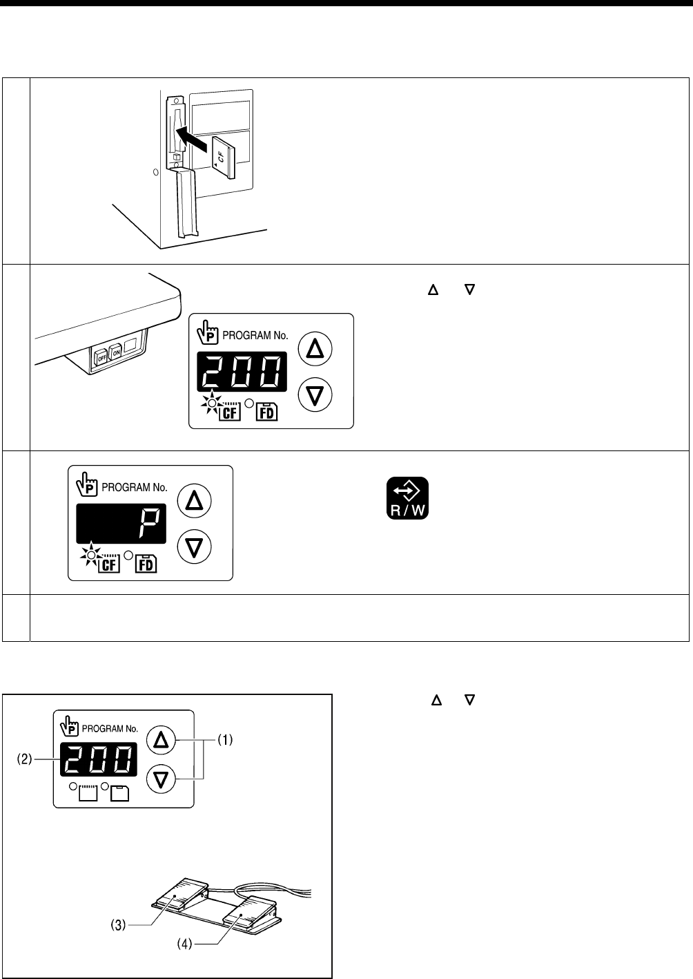
1
With the power turned off, insert the CF card into the CF
slot.
NOTE:
• Make sure the CF card is facing the correct way
when inserting it.
• Always be sure to keep the cover closed except
when inserting and removing the CF card. If this is
not done, dust may get inside and cause problems
with operation.
2
CF media indicator illuminates
Turn on the power switch.
Press the or key to select the program number
(100 − 999).
* The "---" display is used to check the feed home
position.
3
Loading
Press the R/W key.
• The buzzer will sound and the selected sewing data
will be loaded from the CF card and copied into the
sewing machine's internal memory.
4 Loading complete
The PROGRAM No. display will change from " P" to the selected program number.
Turn off the power switch, remove the CF card, and then close the cover of the CF slot.
6-3. Setting the program number
1. Press the or key (1) to select the program number
that is loaded into the internal memory.
• The program number will flash in the PROGRAM No.
display (2).
• "---" will appear at the time of shipment from the
factory. (For checking feed home position)
2. Depress the work clamp switch (3) to lower the work
clamp, and then depress the start switch (4).
• The work clamp will move to the sewing start position,
and then the program number will be applied.
• The program number will stop flashing and illuminate
steadily.
NOTE:
After completing the setting, be sure to refer to "6-6.
Checking the sewing pattern" to check that the needle
drop position is correct.
4457Q
4421Q
4453Q
4498Q
4012M
6. USING THE OPERATION PANEL (BASIC OPERATIONS)
BAS-342G PS 30
6-4. Setting the X-scale and Y-scale
The scales are set to 100 (%) at the time of shipment from
the factory.
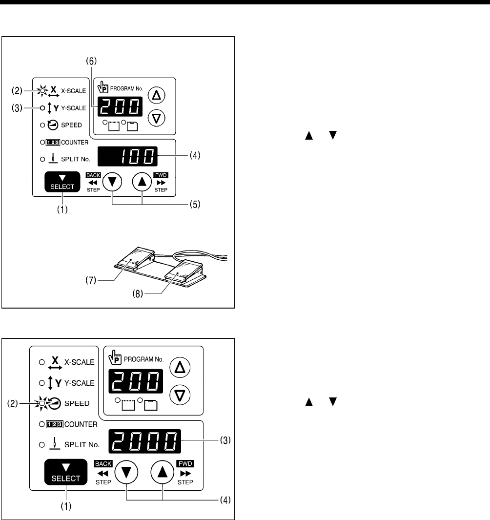
1. Press the SELECT key (1) so that the X-SCALE
indicator (2) (for X-scale setting) or the Y-SCALE
indicator (3) (for Y-scale setting) is illuminated.
• The setting value (%) will appear in the menu display
(4).
* When memory switch no. 402 is set to "ON", the
settings will be displayed in units of mm.
2. Press the or key (5) to set the scale (0 − 400).
• The program number will flash in the PROGRAM No.
display (6).
3. Depress the work clamp switch (7) to lower the work
clamp, and then depress the start switch (8).
• The work clamp will move to the sewing start position,
and then the scales will be applied.
• The program number will stop flashing and illuminate
steadily.
NOTE:
After completing the setting, be sure to refer to "6-6.
Checking the sewing pattern" to check that the needle
drop position is correct.
6-5. Setting the sewing speed
The sewing speed is set to 2000 (sti/min) at the time of
shipment from the factory.
1. Press the SELECT key (1) until the SPEED indicator (2)
illuminates.
• The setting value (sti/min) will appear in the menu
display (3).
2. Press the or key (4) to set the sewing speed.
(Sewing speed setting: 400 − 2700)
4956Q
4013M
6. USING THE OPERATION PANEL (BASIC OPERATIONS)
31 BAS-342G PS
6-6. Checking the sewing pattern
Use test feed mode to check the needle movement with only the work clamp operating.
Check that the needle hole in the needle plate does not come out from the frame of the work clamp.
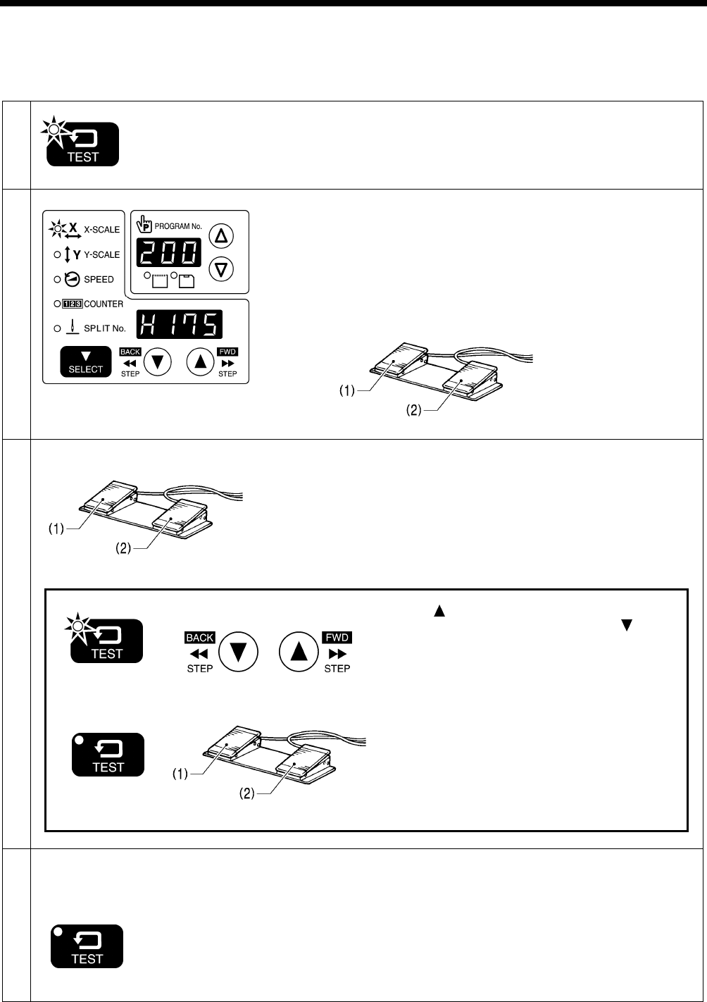
1
TEST indicator illuminates
Press the TEST key.
2
COUNTER indicator illuminates
Select the program number to be checked, and then set the X-scale and
the Y-scale.
• The program number will flash.
Depress the work clamp switch (1) to lower the work clamp, and then
depress the start switch (2).
• The work clamp will move to the sewing start position, and then the
program number will stop flashing and illuminate steadily.
• The number of stitches will appear in the menu display.
Starting continuous test feed mode
Depress the work clamp switch (1) to lower the work clamp, and then
depress and release the start switch (2).
• The work clamp will start moving continuously one stitch at a time.
[Fast-forward test mode]
If the work clamp switch (1) is depressed while the work clamp is moving,
the feeding speed can be increased while the work clamp switch (1) is
depressed.
TEST indicator illuminates
When the key is pressed, the work clamp will move
forward by one stitch, and when the key is
pressed, the work clamp will move backward by one
stitch. (It will move quicker if you keep the key pressed
down.)
TEST indicator switches off
If you would like sewing to start while test feeding is in
progress, press the TEST key to switch off the TEST
indicator.
When the start switch (2) is depressed, sewing will
start.
3
4 If test feeding continues until the
final stitch, the work clamp will move
to the sewing start position and then
stop.
TEST indicator switches off
Press the TEST key.
4957Q 4014M
4014M
4014M
4443Q
6. USING THE OPERATION PANEL (BASIC OPERATIONS)
BAS-342G PS 32
6-7. Setting the height of the intermittent presser foot
You can use the operation panel to change the setting value for the intermittent presser foot height.
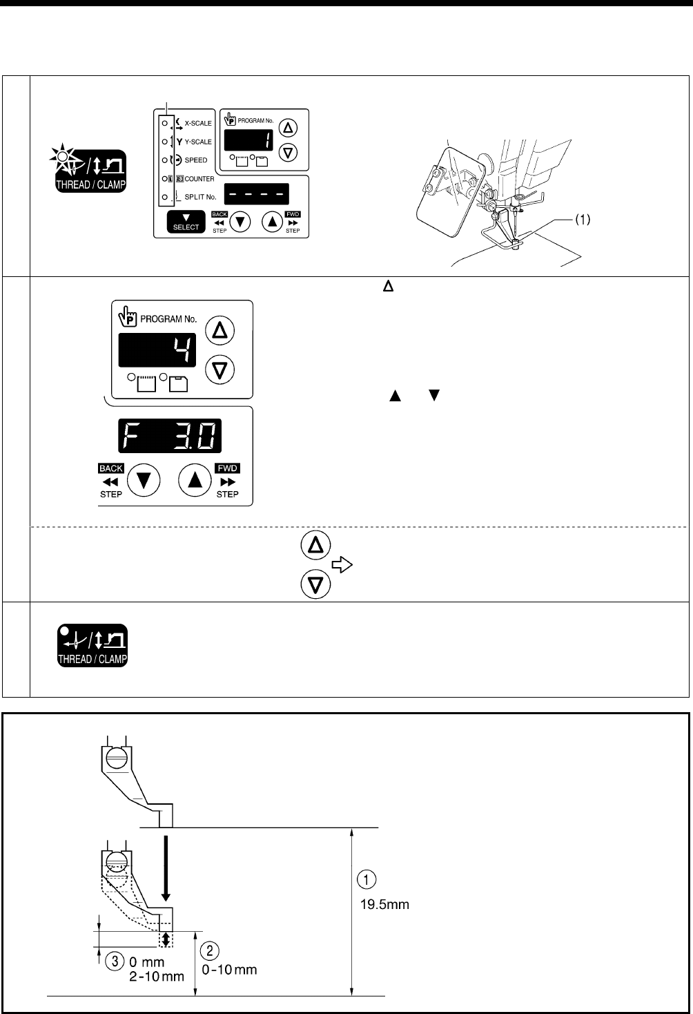
1
THREAD/CLAMP indicator illuminates
MENU indicator switches off
Press the THREAD/CLAMP key.
The sewing machine will switch to threading mode.
• " 1" will appear in the PROGRAM No. display and the
intermittent presser foot (1) will drop.
2
Press the key.
The sewing machine will switch to intermittent presser foot height
setting mode.
• " 4" will appear in the PROGRAM No. display and the
intermittent presser foot (1) will rise to the setting value that
appears in the menu display.
(Intermittent presser foot height setting: 0.0 − 10.0)
Press the or key to set the intermittent presser foot
height.
• The intermittent presser foot (1) will be raised or lowered to the
height of the new value that has been set.
NOTE:
After making the setting, be sure to turn the pulley once by
hand and check that the intermittent presser foot (1) does not
touch the needle bar.
<Changing modes>
" 1" Threading mode
↑ ↓
" 4" Intermittent presser foot height setting mode
3 Ending setting mode
THREAD/CLAMP indicator switches off
Press the THREAD/CLAMP key.
• The setting values will be memorized.
• The intermittent presser foot (1) will return to the status that it
was at before the sewing machine was switched to setting
mode.
Intermittent presser foot operation
1 Intermittent presser foot lift amount
2 Intermittent presser foot height
The settings can be made by the above
operations.
However, if the intermittent presser foot
height is set to a smaller setting than the
intermittent presser foot stroke, the
intermittent presser foot will not drop in
order to prevent it from coming into contact
with the needle plate. (Refer to page 64.)
3 Intermittent stroke
Refer to "11-13. Changing the intermittent
stroke" when making the adjustment.
All indicators switch off
5225Q
During standby
When lowered
While sewing
4445Q 2158B
4016M
2763B
7. USING THE OPERATION PANEL (ADVANCED OPERATIONS)
33 BAS-342G PS
7. USING THE OPERATION PANEL
(ADVANCED OPERATIONS)
7-1. List of advanced functions
While holding down the TEST key, press the corresponding combination key.
1
Memory switch setting mode
Refer to "7-2. Setting memory switches".
2
Lower thread counter setting mode
Refer to "7-4. Using the lower thread counter".
3
Production counter setting mode
Refer to "7-5. Using the production counter".
4 When SPEED indicator is illuminated
Production counter temporary display function
Refer to "7-5. Using the production counter".
5
User program setting mode
Refer to "7-7. Using user programs".
4488Q
4489Q
4493Q
4490Q
4492Q
4491Q
7. USING THE OPERATION PANEL (ADVANCED OPERATIONS)
BAS-342G PS 34
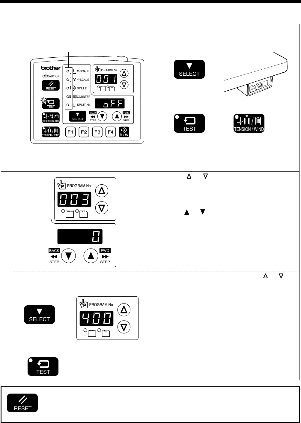
7-2. Setting memory switches
1
Menu indicator switches off
TEST indicator illuminates
While pressing the SELECT key, turn on the power
switch.
* Keep pressing the SELECT key until the model name
is displayed and the buzzer beeps once.
or
With the power turned on, press the TEST key and the
TENSION/WIND key simultaneously.
• The memory switch number will appear in the
PROGRAM No. display, and its setting value will
appear in the menu display.
2
Press the or key to select the memory switch
number.
(Refer to "7-3. List of memory switch settings" on the next
page.)
Press the or key to change the setting.
If you would like to display only the numbers of
memory switches that have been changed from
default settings
While pressing the SELECT key, press the or key.
• The numbers of memory switches that have been
changed from default settings will appear in order.
• If no memory switches have been changed from their
default settings, the display will not change and the
buzzer will beep twice.
3 Ending setting mode
TEST indicator switches off
Press the TEST key.
• The changes will be memorized and the sewing
machine will switch to home position detection standby.
• If you would like to return the setting for a single memory switch to the default setting, press the
RESET key while the number for that memory switch is displayed.
• To return the settings for all memory switches to the default settings, keep pressing the RESET key
for two or more seconds until the buzzer makes a long beep.
4421Q
4449Q
4961Q
4452Q
All indicators switch off

7. USING THE OPERATION PANEL (ADVANCED OPERATIONS)
35 BAS-342G PS
7-3. List of memory switch settings
No. Setting
range Setting items Initial value
Work clamp lift timing after sewing is completed
OFF Lifts at the final stitch position.
001
ON Lifts after moving to the sewing start position.
ON
Integrated-type work clamp drop operation
0 Work clamp dropping in one step
1 Work clamp dropping in two steps (*1)
002
2 Do not use this setting.
0
Sewing start speed
OFF
The sewing speed for the first 1 − 5 stitches is set by memory switch numbers 151
− 155.
(Refer to the service manual for details of memory switch Nos. 151 − 155.)
100
ON 1st stitch at 400 sti/min, 2nd stitch at 400 sti/min, 3rd stitch at 600 sti/min, 4th
stitch at 900 sti/min, 5th stitch at 2,000 sti/min
OFF
Single-stitch test feed
OFF Test feed starts when the start switch is depressed, and it continues automatically
until the final stitch.
200
ON
Test feeding
• Is carried out one stitch at a time each time the work clamp switch is depressed
• Is carried out continuously while the start switch is depressed
• Is carried out one stitch at a time when the pulley is turned by hand
OFF
Production counter display
OFF Lower thread counter display
300
ON Production counter display
OFF
User programs
OFF Disabled
400
ON User program mode is enabled.
OFF
Cycle programs
OFF Disabled
401
ON When sewing user programs, the set programs are sewn in numeric order.
OFF
Maximum reduction ratio (mm display) (*2)
OFF Displayed as %.
402
ON Displayed as mm.
OFF
Split mode selection
0 Continuous split (split menu is disabled before split detection)
1 Continuous split (split menu is always enabled)
403
2 Independent split
0
Thread trimming air cylinder operation timing
900 0 − 200 The larger the value, the more delayed the timing. 0
(*1) The position of the work clamp stopper must be set. (Refer to "5-8. Setting 2-step operation for the work clamp".)
(*2) The mm display may differ slightly from the actual sewing size.
7. USING THE OPERATION PANEL (ADVANCED OPERATIONS)
BAS-342G PS 36
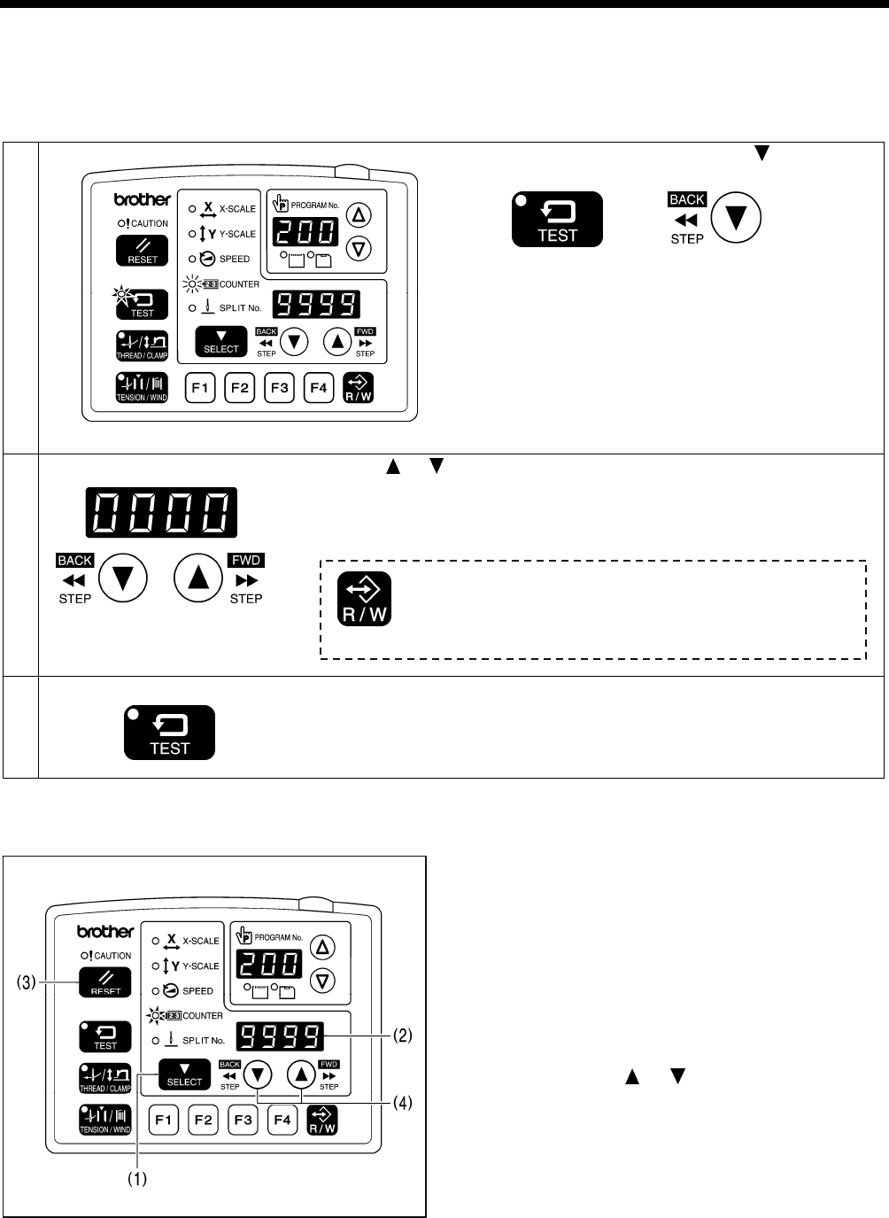
7-4. Using the lower thread counter
If you use the lower thread counter to set the number of articles which can be sewn with the amount of lower thread
available, you can stop the lower thread running out in the middle of sewing a pattern.
<Setting defaults>
1
TEST indicator illuminates, COUNTER indicator flashes
While pressing the TEST key, press the key.
• The initial value which was set previously will appear in
the menu display.
2 Press the or key to set the initial value.
• The initial value can be set from 1 ("0001") to 9999 ("9999").
• If the initial value is set to "0000", the lower thread counter will not operate.
• If you press the RESET key during setting mode, the value will become
"0000".
3 Ending setting mode
TEST indicator switches off
Press the TEST key.
• The initial value will be memorized.
<Lower thread counter operation>
If you press the SELECT key (1) to select the counter display menu when memory switch no. 300 is set to "OFF", the
COUNTER indicator will illuminate and the lower thread counter will appear in the menu display (2).
1. Each time the sewing of a single article is completed,
the value shown in the menu display (2) is reduced by 1.
2. When the lower thread counter reaches "0000", the
buzzer will sound continuously. The sewing machine will
not operate during this time, even if the foot switch is
depressed.
3. When you press the RESET key (3), the buzzer will stop,
the initial value will appear in the menu display (2) and
sewing will be possible.
• If no initial value has been set, the display will be
"0000".
* You can press the or key (4) to set the lower
thread counter to a desired value. However, this value
will not be stored as the initial value.
* If a lower thread counter value is set, the lower thread
counter will operate even if the lower thread counter is
not being displayed.
4455Q
4962Q
4456Q
4963Q
If you press the R/W key during setting mode, the initial value for
the program number being displayed will be stored, and you can
set the lower thread counter separately for each item of sewing
data.
7. USING THE OPERATION PANEL (ADVANCED OPERATIONS)
37 BAS-342G PS
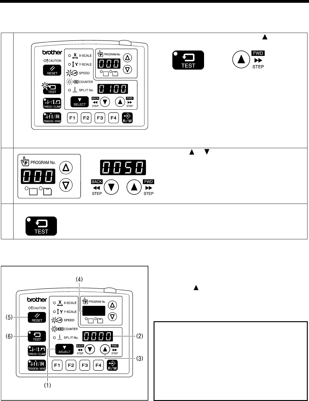
7-5. Using the production counter
<Setting the counter value>
1
TEST indicator and SPEED indicator illuminate
COUNTER indicator flashes
While pressing the TEST key, press the key.
• The counter value that was previously set will appear
as a 7-digit number in the PROGRAM No. display and
the menu display.
2
Press the or key to set the counter value.
• The counter value can be set to between "000" "0000"
and "999" "9999".
• If you press the RESET key during setting mode, the
value will become "000" "0000".
3 Ending setting mode
TEST indicator switches off
Press the TEST key.
• The counter value will be memorized.
<Production counter operation>
If you press the SELECT key (1) to select the counter display menu when memory switch no. 300 is set to "ON", the SPEED
and COUNTER indicators will illuminate and the production counter will appear in the menu display (2).
1. Each time the sewing of a single article is completed,
the value shown in the menu display (2) is increased by
1.
2. While the key (3) is being pressed, the first three
digits will appear in the PROGRAM No. display (4) so
that the total number of digits displayed will be seven.
3. If you press the RESET key (5) for 2 seconds or more,
the counter value will be reset to [0000].
Temporary display function
You can display the production counter temporarily while
the lower thread counter is being displayed.
When the SPEED indicator is illuminated, hold down the
TEST key (6) and then press the RESET key (5) to display
the production counter in the menu display (2).
Press the TEST key (6) or the SELECT key (1) to switch the
menu back to the normal menu display.
* You can start sewing while the temporary display still
appears.
4465Q4464Q
4466Q
4468Q
7. USING THE OPERATION PANEL (ADVANCED OPERATIONS)
BAS-342G PS 38
7-6. Setting the split number
If split data (data that causes sewing to pause) exists within a single program,
the numbers that are used to specify the patterns that are separated by split
data are called split numbers.
Pattern 1: Split No. 1
Pattern 2: Split No. 2
Pattern 3: Split No. 3
1. Press the or key (1) to select a program number
for a program that contains split data.
• The program number will flash in the PROGRAM No.
display (2).
2. Depress the work clamp switch (3) to lower the work
clamp, and then depress the start switch (4).
• The work clamp will move to the sewing start position,
and then the program number will be applied.
• The program number will stop flashing and illuminate
steadily.
3. Press the SELECT key (5) so that the SPLIT No.
indicator (6) illuminates.
• The split number will appear in the menu display (7).
4. Press the or key (8) to set the split number.
The setting for memory switch No. 403 lets you select the split mode.
[Continuous split]
Memory switch No. 403 = 0 (Split mode is enabled after split data is detected)
Memory switch No. 403 = 1 (Split mode is always enabled)
• Sewing is carried out each time in the order of steps 1 → 2 → 3 → 1 (for example, if there are two sections of split
data).
[Independent split]
Memory switch No. 403 = 2
• The pattern for the displayed split number is sewn independently.
4964Q
Pattern 1
Pattern 2
Pattern 3
4017M
7. USING THE OPERATION PANEL (ADVANCED OPERATIONS)
39 BAS-342G PS
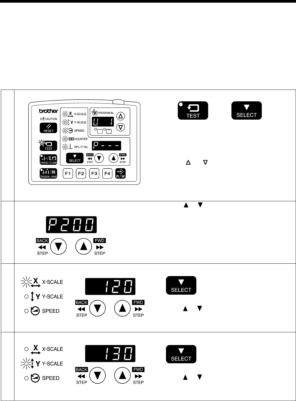
7-7. Using user programs
Up to 50 different combinations of settings including program no., X-scale, Y-scale, sewing speed and intermittent presser
foot height can be memorized as user programs (U1 to U50).
If you are sewing certain patterns over and over again, it is useful to record the settings for these patterns into a user
program.
User programs are enabled when memory switch no. 400 is set to "ON".
<Recording user programs>
1 Select a user program number.
TEST indicator illuminates, MENU indicator flashes
While pressing the TEST key, press the SELECT key.
• Switch to user program recording mode. Check that
the menu indicators are flashing.
• The user program number will appear in the
PROGRAM No. display, and " P- - - " will appear in the
menu display.
Press the or key to select the user program
number.
2 First, set the program number.
Press the or key to set the user program number
to be recorded.
NOTE:
Select a program number that is recorded in the
internal memory. You cannot specify program
numbers on removable media.
3 Next, set the X-scale.
X-SCALE indicator flashes
Press the SELECT key.
Press the or key to set the X-scale to be recorded.
4 Next, set the Y-scale.
Y-SCALE indicator flashes
Press the SELECT key.
Press the or key to set the Y-scale to be recorded.
4469Q
4966Q
4470Q
4472Q
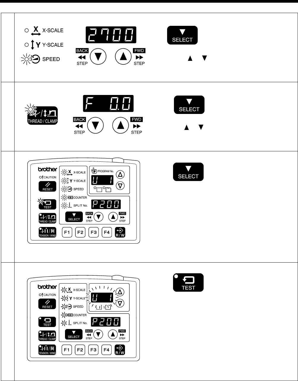
7. USING THE OPERATION PANEL (ADVANCED OPERATIONS)
BAS-342G PS 40
5 Next, set the sewing speed.
SPEED indicator flashes
Press the SELECT key.
Press the or key to set the sewing speed to be
recorded.
6 Next, set the intermittent presser foot height.
THREAD/CLAMP indicator flashes
Press the SELECT key.
Press the or key to set the intermittent presser foot
height to be recorded.
7
TEST indicator illuminates, MENU indicator flashes
Press the SELECT key.
• If setting further user programs, select the user
program number and then repeat steps 2 to 7.
8
End user program recording mode.
TEST indicator switches off, MENU indicator illuminates
Press the TEST key.
This completes the recording of a user program.
• The user program number will flash in the PROGRAM
No. display.
(Continued on next page)
4474Q
4970Q
4971Q
4969Q
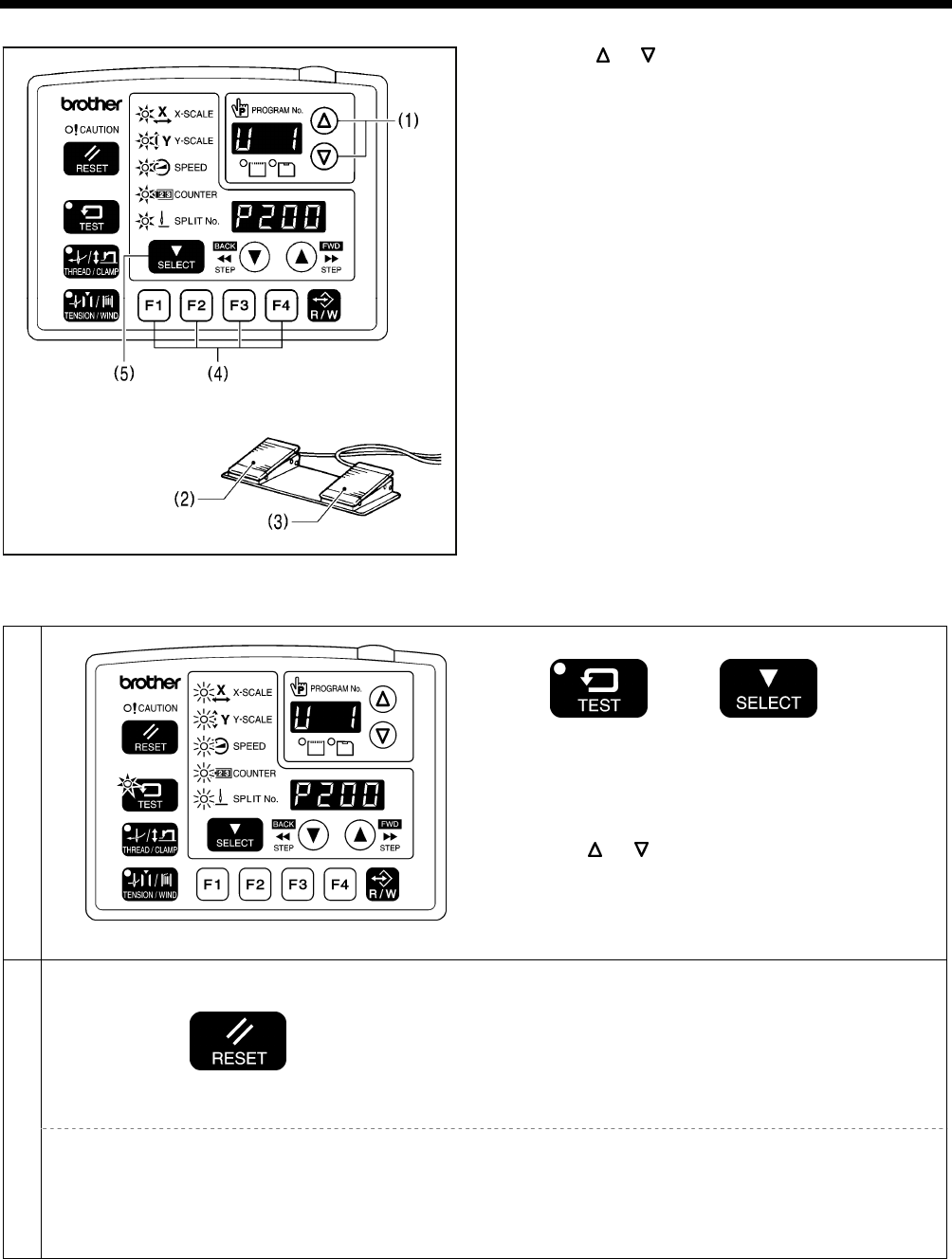
7. USING THE OPERATION PANEL (ADVANCED OPERATIONS)
41 BAS-342G PS
<Setting method>
1. Press the or key (1) to select the user program
number that you would like to use.
• If the user program number is flashing, depress the
work clamp switch (2) to lower the work clamp, and
then depress the start switch (3). (The work clamp
will move to the sewing start position.)
• User programs U1 to U10 can be selected directly
using function keys F1 to F4 (4). (Refer to "7-9. Direct
selection".)
2. Check that the needle drop position is correct, and then
start sewing. (Refer to "6-6. Checking the sewing
pattern".)
• If you press the SELECT key (5), you can check the
settings for the displayed user program (such as X-scale,
Y-scale and sewing speed).
<Clearing method>
1
TEST indicator illuminates, MENU indicator flashes
While pressing the TEST key, press the SELECT key
• Switch to user program recording mode. Check that
the menu indicators are flashing.
• The user program number will appear in the
PROGRAM No. display, and the program number will
appear in the menu display.
Press the or key (1) to select the user program
number that you would like to clear.
2
Press the RESET key.
• The buzzer will sound and the user program with the
number selected will be cleared.
NOTE:
If a cleared user program has been stored as part of
a cycle program, the step that involves that user
program will become blank. The cycle program itself
will not be cleared.
Clearing all user programs
Press and hold the RESET key for 2 seconds or more.
• The buzzer will sound and all user programs will be
cleared.
NOTE:
If any cycle programs have been memorized, all of
the memorized cycle programs will also be cleared.
4970Q
4018M
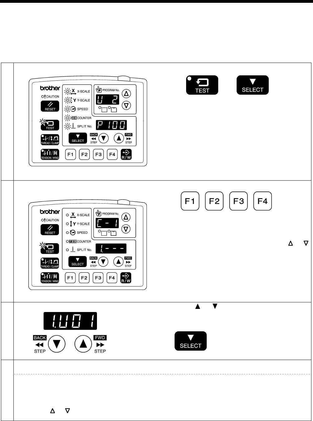
7. USING THE OPERATION PANEL (ADVANCED OPERATIONS)
BAS-342G PS 42
7-8. Using cycle programs
Sewing patterns that have been recorded in user programs can be recorded in up to nine cycle programs (C-1 to C-9).
One cycle program can contain up to a maximum of fifteen steps.
When sewing the sewing patterns in numerical order, it can be useful to record them in a cycle program beforehand.
Cycle programs are enabled when memory switch nos. 400 and 401 are set to "ON".
<Recording method>
1 Switch to user program recording mode.
TEST indicator illuminates, MENU indicator flashes
While pressing the TEST key, press the SELECT key.
• Check that the menu indicators are flashing.
• The user program number will appear in the
PROGRAM No. display, and the program number will
appear in the menu display.
Record the sewing pattern that you would like to use in a
cycle program into a user program.
2 Switch to cycle program recording mode, and select
the cycle program number.
MENU indicator switches off
Press a function key from F1 to F4.
• The cycle program number (C-1 to C-4) will appear in
the PROGRAM No. display, and "1.---" will appear in
the menu display.
Press the function key (F1 to F4) or press the or
key to select the cycle program number.
3 Set step 1.
Press the or key to select the user program
number that you would like to record.
Press the SELECT key.
4 Set the rest of the steps in the same way from step 2 onward.
From step 9 onward, "A.---", "b.---", "c.---", "d.---", "E.---" and "F.---" will be displayed.
If you would like to return to a previous step during the setting procedure
<For cycle programs C-1 to C-4>
1. Press the respective function key from F1 to F4 to return to the display for step 1.
2. Press the SELECT key until the desired step is reached.
<For cycle programs C-5 to C-9>
1. Press the or key to switch the cycle program number.
2. Select the desired cycle program number again, and then press the SELECT key until the desired step is reached.
4973Q
4428Q
4444Q
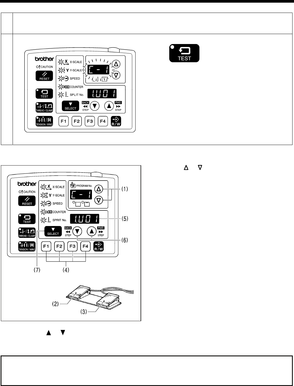
7. USING THE OPERATION PANEL (ADVANCED OPERATIONS)
43 BAS-342G PS
5 To record another cycle program, repeat steps 2 to 4.
6 End cycle program recording mode.
TEST indicator switches off, MENU indicator illuminates
Press the TEST key.
This completes the recording of cycle programs.
• The cycle program number will flash in the PROGRAM
No. display.
<Setting method>
1. Press the or key (1) to select the cycle program
number that you would like to use.
• If the cycle program number is flashing, depress the
work clamp switch (2) to lower the work clamp, and
then depress the start switch (3). (The work clamp
will move to the sewing start position.)
• The cycle program number can be selected directly
by pressing function keys F1 to F4 (4). (Refer to "7-9.
Direct selection".)
2. Check that the needle drop position is correct, and then
start sewing. (Refer to "6-6. Checking the sewing
pattern".)
3. The recorded user program will be sewn step by step,
and when the final step is complete, the menu display
(5) will return to showing step 1.
• If you press the or key (6), you can return to the previous step or skip to the next step respectively.
• If you press the SELECT key (7), you can check the details (such as X-scale, Y-scale and sewing speed) of the user
program for the displayed step. The setting cannot be changed at this time.
NOTE:
If cycle program sewing mode is active (when memory switch no. 401 is "ON") but no cycle programs have been
recorded, the user programs will be sewn in numeric order.
“C-0” will appear in the PROGRAM No. display at this time.
4439Q
4019M
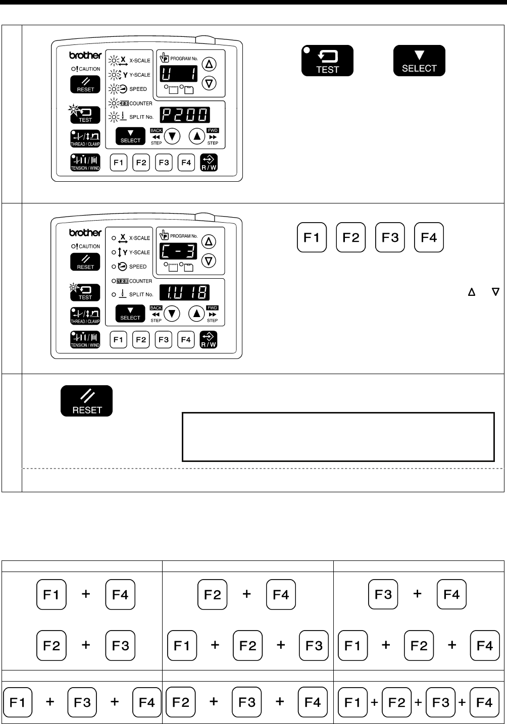
7. USING THE OPERATION PANEL (ADVANCED OPERATIONS)
BAS-342G PS 44
<Clearing method>
1
TEST indicator illuminates, MENU indicator flashes
While pressing the TEST key, press the SELECT key.
• Switch to user program recording mode. Check that
the menu indicators are flashing.
2
MENU indicator switches off
Press a function key from F1 to F4.
• Switch to cycle program recording mode.
Press the function key (F1 to F4) or press the or
key to select the cycle program number to clear.
3
Press the RESET key.
• The buzzer will sound and the cycle program with the number selected will
be cleared.
NOTE: If you clear all user programs after any cycle programs have been recorded, all recorded cycle programs will
also be cleared.
7-9. Direct selection (combination table)
You can use the function keys to directly select user program numbers and cycle program numbers.
U1 to U4 and C-1 to C-4 can be selected using function keys F1 to F4.
U5 to U10 and C-5 to C-9 can be selected by simultaneously pressing combinations of function keys F1 to F4 (addition).
U5/C-5 U6/C-6 U7/C-7
Or
Or
Or
U8/C-8 U9/C-9 U10
4970Q
4450Q
Clearing all cycle programs
Press and hold the RESET key for 2 seconds or more.
• The buzzer will sound and the all cycle programs will be cleared.
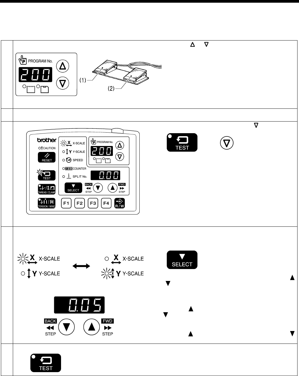
7. USING THE OPERATION PANEL (ADVANCED OPERATIONS)
45 BAS-342G PS
7-10. X and Y parallel movement of sewing pattern
You can move the feed mechanism to the desired position to move an already-programmed sewing pattern in a parallel
direction up, down or to the left or right.
1
1. Press the or key to select the program number.
2. Depress the work clamp switch (1) to lower the work
clamp, and then depress the start switch (2).
• The work clamp will move to the sewing start
position.
2 Depress the work clamp switch (1) to lower the work clamp.
3
TEST indicator illuminates, X-SCALE indicator flashes
While pressing the TEST key, press the key.
• The parallel movement amount will appear in the menu
display in units of mm.
4
X-scale Y-scale
parallel movement mode parallel movement mode
Press the SELECT key to switch between the X-SCALE
indicator and Y-SCALE indicator flashing. Select either
direction.
The work clamp will move by 0.05 mm each time the
or key is pressed. (When the distance reaches 10
mm, the amount of movement will change to 0.1 mm.)
• When using X-scale parallel movement mode, the
needle moves the corresponding distance to the right
when the key is pressed, and to the left when the
key is pressed.
• When using Y-scale parallel movement mode, the
needle moves the corresponding distance backward
when the key is pressed, and forward when the
key is pressed.
5 End parallel movement mode
TEST indicator switches off
Press the TEST key.
NOTE:
• The feed mechanism will not move to a position that would move the sewing pattern outside the sewing area.
• If you change the program number, X-scale or Y-scale settings, the amount of movement recorded will be reset.
• In addition, the amount of movement will be reset if the power switch is turned off and then back on again. However,
memory switch No. 465 is set to "ON", the amount of movement will be recorded and will not be reset. (Refer to the
service manual for details on memory switch No. 465.)
4974Q 4014M
4975Q 4559Q
4561Q
4560Q
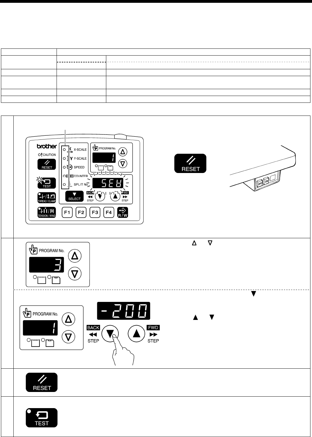
7. USING THE OPERATION PANEL (ADVANCED OPERATIONS)
BAS-342G PS 46
7-11. Clearing memory data (reinitialization)
If the sewing machine stops operating normally, the cause may be that an incorrect memory setting may have been made by
means of the memory switch, for instance. In such cases, normal operation may be restored if the memory data is
reinitialized.
Parameter No. Setting items
[ SEW] Clearing all sewing programs
1 [−***] Clearing individual sewing programs
2 [ MEM] Reinitializing memory switches
3 [ ALL]
Clearing or reinitializing all memory data (sewing programs, memory switches,
user programs, cycle programs and expansion option output data)
4 [ USE] Clearing user programs and cycle programs
5 [ EoP] Clearing expansion option output data
* Refer to the instruction manual for the programmer for details of expansion option output.
1
TEST indicator illuminates, MENU indicator switches off
While holding down the RESET key, turn on the power
switch.
* Keep pressing the RESET key until the model name is
displayed and the buzzer beeps once.
• The parameter number will appear in the PROGRAM
No. display, and the setting details for that parameter
will appear in the menu display.
2
Press the or key to select the parameter number
that you would like to reinitialize.
Selecting individual sewing programs
For parameter No. 1, press the key to change the
display from " SEW" to "−***".(*** is the sewing program
number.)
Press the or key to select the sewing program
number that you would like to clear.
3
Press and hold the RESET key for 2 seconds or more.
• A long beep will sound and the data for the selected item will be reinitialized.
• The setting details for only the initialized item will change from flashing to
steadily illuminated.
4 End data initialization mode
TEST indicator switches off
Press the TEST key.
All indicators switch off
4562Q 4421Q
4557Q
4563Q

8. USING CF CARDS
47 BAS-342G PS
8. USING CF CARDS
8-1. Notes on handling CF cards (sold separately)
• Use a CF card with a memory capacity of 32, 64, 128, 256, 512 MB, 1GB or 2GB.
(CF cards with a capacity of more than 2GB are not supported.)
• Do not disassemble or modify the CF card.
• Do not bend, drop or scratch CF cards or place heavy objects on top of them.
• Avoid contact with liquids such as water, oil, solvents or drinks.
• Use and store CF cards in locations that are free from strong static electricity and electrical interference.
• Do not use or store CF cards in places where they may be subject to vibrations or shocks, direct sunlight, high
temperature or humidity or strong magnetic fields from equipment such as speakers, or places which are dusty from thread
scraps, etc.
• Do not subject CF cards to shocks or impacts or remove them from the sewing machine while data is being loaded or
written.
• The data on the CF cards may become lost or corrupted due to some malfunction or accident. It is recommended that you
make a backup of important data.
• CF cards should only be removed after the power for the sewing machine has been turned off.
• CF cards are already formatted when they are purchased, and so you should not reformat them.
• The recommended CF cards are commercially-available ones from SanDisk or HAGIWARA SYS-COM. CF cards from
other manufacturers can be used, but different formatting methods may mean that loading from or writing to such cards
may not be possible.
For more information, refer to the documentation provided with the CF card.
* This product is compatible with CF cards that have been formatted using the FAT16 method. Cards that have been
formatted using the FAT32 method cannot be used.
* CFTM is a trademark of SanDisk Corporation.
* Company names and product names appearing in this manual are trademarks or registered trademarks of the
respective owners. However, no TM or other similar symbols appear in the main text of this manual.
8-2. Structure of a CF card folder
\BROTHER\ISM\ISMSYS\ISM05MN.MOT : Control program
\BROTHER\ISM\ISMDB00\ISMMSW.SEW : Memory switch data
*1 \ISMUPG.SEW : User program data
\ISMS0100.SEW : Sewing data P No. = 100
\ISMS0101.SEW : Sewing data P No. = 101
\ISMS0102.SEW : Sewing data P No. = 102
*1 The underlined portion of the name of the \BROTHER\ISM\SMDB00 folder for sewing data can be changed by
changing the setting for memory switch No. 752 in order to change the folder name. Change the folder name if you
would like to store sewing data for different sewing machines on a single CF card. (Refer to the service manual for
details on memory switch No. 752.)
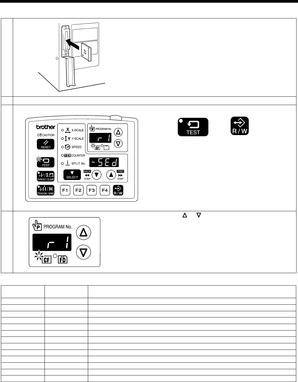
8. USING CF CARDS
48
BAS-342G PS
8-3. Data read/write mode
1
With the power turned off, insert the CF card into the CF
slot.
NOTE:
• Make sure the CF card is facing the correct way.
• Always be sure to keep the cover closed except
when inserting and removing the CF card. If this is
not done, dust may get inside and cause problems
with operation.
• If no valid data can be found, the CF media indicator
will not illuminate.
2 Turn on the power switch.
3 Switch to data read/write mode.
TEST indicator and CF media indicator illuminate
While pressing the TEST key, press the R/W key.
• The mode number will appear in the PROGRAM No.
display, and the setting details for that mode will
appear in the menu display.
• The initial mode is sewing data reading mode. (Refer
to the read/write mode list)
4
Press the or key to select the mode.
[Read/write mode list]
PROGRAM No.
display Menu display Setting items
r 1 [-SEd] Sewing data is read from the CF card. (*1)
w 2 [SEd-] Sewing data is written to the CF card.
r 3 [-MEM] Memory switch settings are read from the CF card.
w 4 [MEM-] Memory switch settings are written to the CF card.
r 5 [-UPG] User programs are read from the CF card.
w 6 [UPG-] User programs are written to the CF card.
r 7 [-SyS] Control programs are read from the CF card and used to update the firmware version.
w 8 [LoG-] Error log data is written to the CF card.
r 9 [-Fdd] Sewing data is read from the floppy disk. (*2) (*3)
w 10 [Fdd-] Sewing data is written to the floppy disk. (*2)
r 11 [-EoP] Expansion option output (*4) data is read from the CF card.
w 12 [EoP-] Expansion option output data is written to the CF card.
r 13 [oPFd] Expansion option output data is read from the floppy disk. (*2)
*1 The sewing data that can be used with this sewing machine is data that has been created for the BAS-300G series.
*2 Only valid when using an optional floppy disk drive.
*3 Sewing data for the BAS-300 series, BAS-300A series and BAS-300E/F series can be read.
*4 Refer to the instruction manual for the programmer for details of expansion option output.
4453Q
4574Q
4575Q
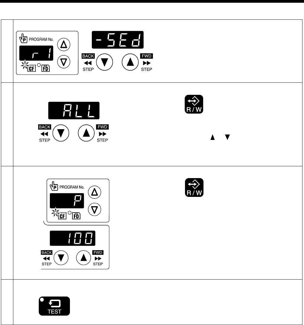
8. USING CF CARDS
49 BAS-342G PS
8-3-1. Reading all sewing data from the CF card at once
1
Select the [r 1] data read/write mode.
2
Press the R/W key.
• [-SEd] will change to [ ALL].
* If you press the or key to select the program
numbers that you would like to read and then continue
to carry out the following procedure, you can read the
selected sewing data in separate lots.
3
Loading
Press the R/W key.
• The buzzer will sound and all sewing data will be
loaded from the CF card and copied into the sewing
machine's internal memory.
• The program numbers that have been read will appear
in the menu display.
* If there is a large volume of data in the CF card, it will
take some time for all of it to be read. To halt the
reading of data, press the STOP switch. If you then
press the RESET key, the display will change back to
[ ALL].
4 End data read/write mode
TEST indicator switches off
Press the TEST key.
Turn off the power switch, remove the CF card, and then
close the cover of the CF slot.
4976Q
4576Q
4577Q
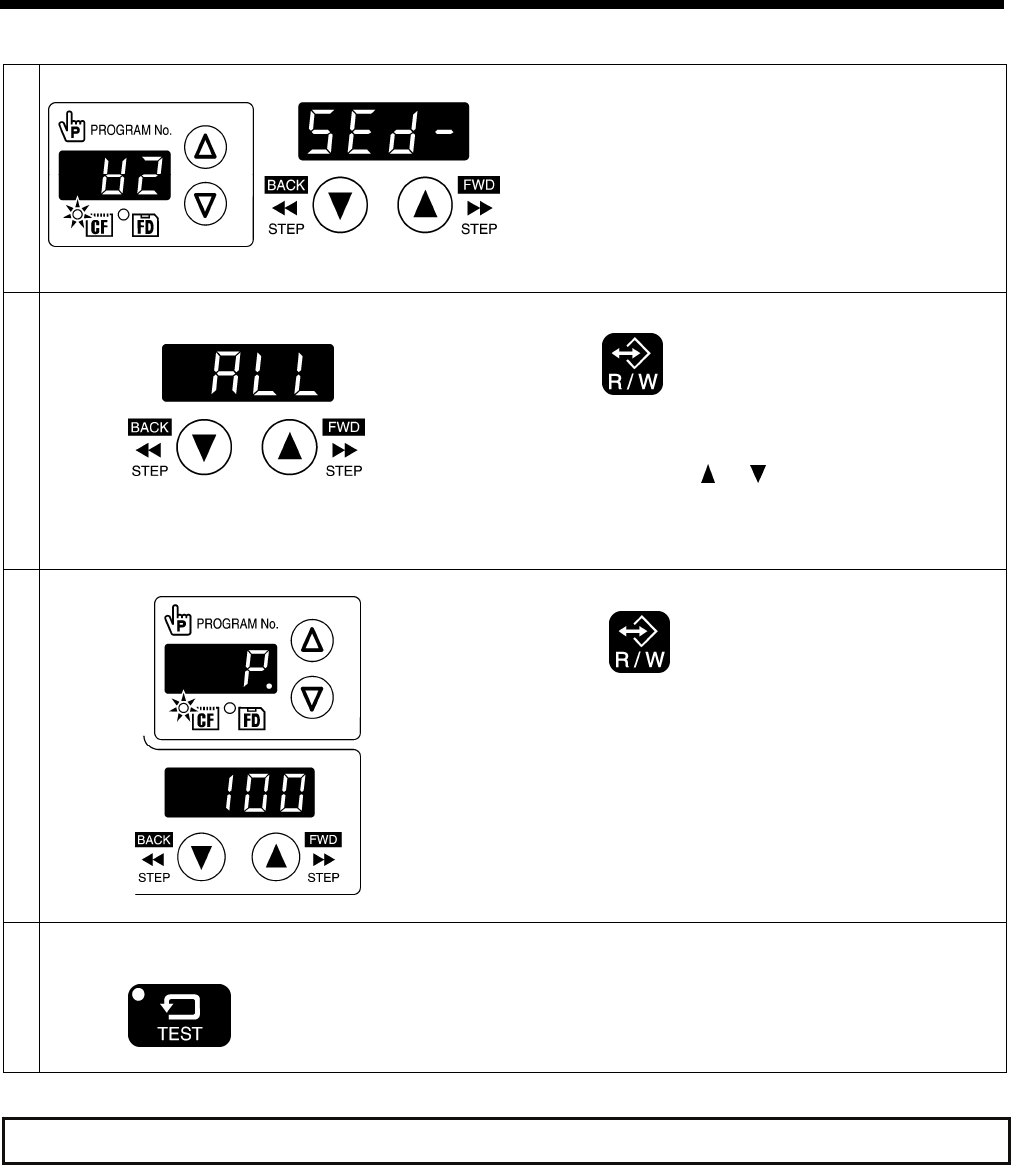
8. USING CF CARDS
50
BAS-342G PS
8-3-2. Writing all sewing data to the CF card at once
1
Select the [w 2] data read/write mode.
2
Press the R/W key.
• [SEd-] will change to [ ALL].
* If you press the or key to select the program
numbers that you would like to write and then continue
to carry out the following procedure, you can write the
selected sewing data in separate lots.
3
Writing
Press the R/W key.
• The buzzer will sound and the all sewing data will be
copied from the internal memory onto the CF card.
• The program numbers that have been written will
appear in the menu display.
* If there is a large volume of data in the internal
memory, it will take some time for all of it to be written.
To halt the writing of data, press the STOP switch. If
you then press the RESET key, the display will change
back to [ ALL].
4 End data read/write mode
TEST indicator switches off
Press the TEST key.
Turn off the power switch, remove the CF card, and then
close the cover of the CF slot.
4578Q
4577Q
Refer to the service manual for details on other read/write modes.
4977Q
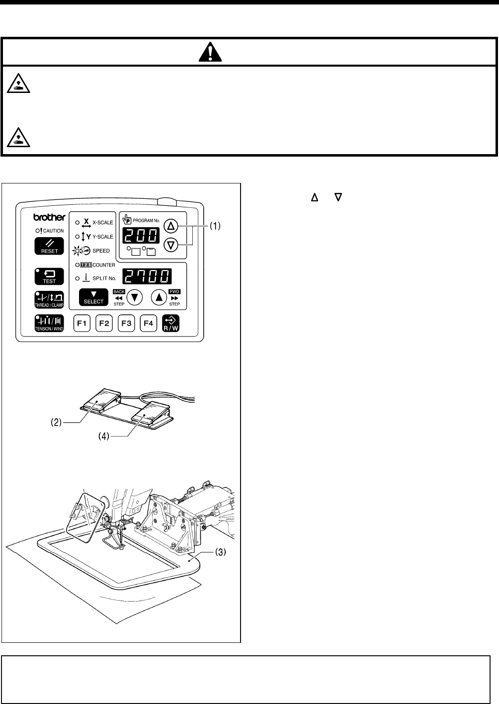
9. SEWING
BAS-342G PS
51
9. SEWING
CAUTION
Turn off the power switch at the following times.
If the foot switch is depressed by mistake, the sewing machine might start operating and injury could result.
• When threading the needle
• When replacing the bobbin and needle
• When not using the machine and when leaving the machine unattended
Do not touch any of the moving parts or press any objects against the machine while sewing, as this may result in
personal injury or damage to the machine.
9-1. Sewing
1. Turn on the power switch.
2. Press the or key (1) to select the sewing program
number that you would like to use.
* Refer to "6-2. Loading sewing data" for details on
reading sewing data from a CF card.
3. Depress the work clamp switch (2) to lower the work
clamp (3), and then depress the start switch (4).
• The work clamp will move to the sewing start
position.
• Home position detection will be carried out
immediately after the power switch is turned on.
4. Place the article to be sewn underneath the work clamp
(3).
5. Depress the work clamp switch (2).
• The work clamp (3) will drop.
6. Depress the start switch (4).
• The sewing machine will start sewing.
7. When sewing is complete, the thread will be trimmed
and the work clamp (3) will rise.
Use a work clamp and a feed plate which will hold the article securely so that it does not slip.
If using the standard work clamp and feed plate and the article being sewn is slipping, take measures to stop the work
clamp and feed plate from being slippery.
4978Q
4020M
2764B
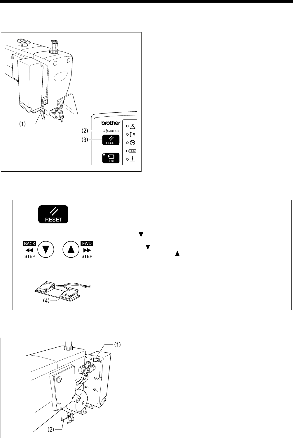
9. SEWING
BAS-342G PS 52
9-2. Using the STOP switch
If you press the STOP switch (1) while sewing or test feeding is in progress, the CAUTION indicator (2) will illuminate and
the sewing machine will stop immediately.
<Clearing>
1. Press the RESET key (3).
• The thread will be trimmed, and then the CAUTION
indicator (2) will switch off and the buzzer will stop
sounding.
2. If you do not wish to continue sewing, press the RESET
key (3) once more.
• The program number will flash. Carry out preparation
for the next sewing.
<Continuing sewing from a stopping point>
If you have pressed the STOP switch (1) at times such as if the thread breaks while sewing or the lower thread runs out, you
can resume sewing from the point where the thread ran out.
1 Press the RESET key.
• The thread will be trimmed, and then the CAUTION indicator will switch
off and the buzzer will stop sounding.
2 Press the key to return the work clamp to the position where sewing is
to be continued.
• When the key is pressed, the work clamp will move backward by one
stitch, and when the key is pressed, the work clamp will move
forward by one stitch. (It will move quicker if you keep the key pressed
down.)
3 Depress the start switch (4).
• The sewing machine will start operating and sewing will start.
9-3. Using the thread wiper switch
The thread wiper switch (1) can be used to turn the thread
wiper (2) on and off.
4982Q
4443Q
4022M
4023M
2264B
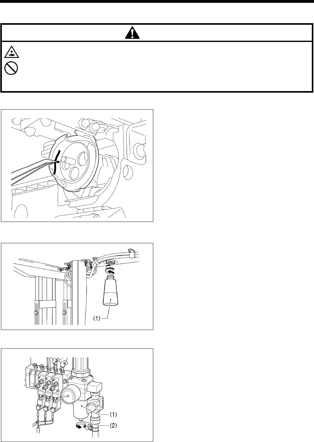
10. CLEANING
BAS-342G PS
53
1877B
10. CLEANING
CAUTION
Turn off the power switch before carrying out cleaning.
If the foot switch is depressed by mistake, the sewing machine might start operating and injury could result.
Be sure to wear protective goggles and gloves when handling the lubricating oil and grease, so that they do not get
into your eyes or onto your skin. If the oil and grease get into your eyes or onto your skin, inflammation can result.
Furthermore, do not drink or eat the lubricating oil or grease. They may cause diarrhea or vomiting.
Keep the oil out of the reach of children.
10-1. Cleaning the rotary hook
Remove the bobbin case, and then remove the thread
scraps and lint from around the shuttle.
Also wipe the bobbin to remove oil.
10-2. Draining the oil
1. Remove and empty the oiler (1) whenever it is full.
2. After emptying oiler (1), screw it back into its original
position.
10-3. Checking the regulator
1. If water collects in the bottle of the regulator (1), turn the
drain cock (2) in the direction of the arrow to drain the
water.
2. After draining the water, tighten the drain cock (2).
2765B
4025M
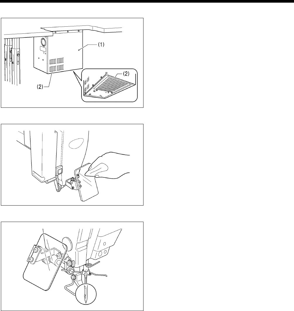
10. CLEANING
BAS-342G PS 54
10-4. Cleaning the control box air inlet ports
Use a vacuum cleaner to clean the filter in the air inlet ports
(2) of the control box (1) at least once a month.
10-5. Cleaning the eye guard
Wipe the eye guard clean with a soft cloth.
NOTE:
Do not use solvents such as kerosene or thinner to clean
the eye guard.
10-6. Checking the needle
Always check that the tip of the needle is not broken and
also that the needle is not bent before starting sewing.
10-7. Lubrication
Lubricate the sewing machine while referring to "4-18. Lubrication".
2766B
4027M
2208B
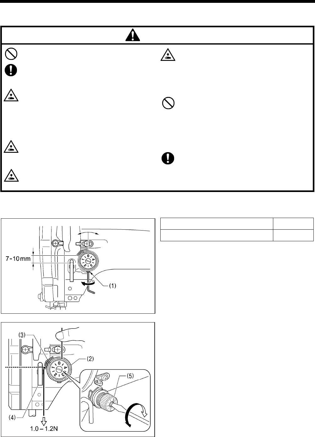
11. STANDARD ADJUSTMENTS
BAS-342G PS
55
11. STANDARD ADJUSTMENTS
CAUTION
Maintenance and inspection of the sewing machine
should only be carried out by a qualified technician.
Ask your Brother dealer or a qualified electrician to
carry out any maintenance and inspection of the
electrical system.
Turn off the power switch and disconnect the power
cord before carrying out the following operations.
If the foot switch is depressed by mistake, the sewing
machine might start operating and injury could result.
• Inspection, adjustment and maintenance
• Replacing consumable parts such as the rotary
hook
Disconnect the air hoses from the air supply and wait
for the needle on the pressure gauge to drop to “0”
before carrying out inspection, adjustment and repair
of any parts which use the pneumatic equipment.
If the power switch and air need to be left on when
carrying out some adjustment, be extremely careful
to observe all safety precautions.
Hold the machine head with both hands when tilting it
back or returning it to its original position.
In addition, do not subject the machine head to extra
force while it is tilted back. If this is not observed, the
machine head may become unbalanced and fall
down, and serious injury or damage to the sewing
machine may result.
Be sure to wear protective goggles and gloves when
handling the lubricating oil and grease, so that they
do not get into your eyes or onto your skin. If the oil
and grease get into your eyes or onto your skin,
inflammation can result.
Furthermore, do not drink or eat the lubricating oil or
grease. They may cause diarrhea or vomiting.
Keep the oil out of the reach of children.
If any safety devices have been removed, be
absolutely sure to re-install them to their original
positions and check that they operate correctly
before using the machine.
11-1. Adjusting the thread take-up spring
Thread take-up spring height (mm) 7 − 10
Thread take-up spring tension (N) 1.0 − 1.2
<Thread take-up spring height>
Loosen the set screw (1) and turn the adjuster to adjust.
<Thread take-up spring tension>
1. Press the upper thread slightly above the tension
bracket (2) with a finger to stop the thread spooling out.
2. Pull the upper thread downward so that the thread
take-up spring (3) is extended to the same height as the
base of the thread guide arm (4), and then measure the
tension of the thread take-up spring (3).
3. Use a screwdriver to turn the tension stud (5) in order to
adjust the tension of the thread take-up spring (3).
NOTE:
If the thread tension spring (3) is not adjusted correctly, the upper thread trailing length will be uneven after thread
trimming.
Lower Higher
4029M
Weaker
Stronger
2767B
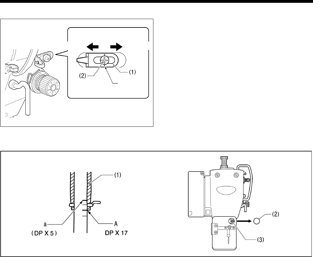
11. STANDARD ADJUSTMENTS
BAS-342G PS 56
11-2. Adjusting arm thread guide R
The standard position of arm thread guide R (1) is when the
screw (2) is aligned with the index mark.
Loosen the screw (2) and move arm thread guide R (1) to
adjust.
* When sewing heavy material, move arm thread guide R
(1) to the left. (The thread take-up amount will become
greater.)
* When sewing light material, move arm thread guide R
(1) to the right. (The thread take-up amount will become
less.)
11-3. Adjusting the needle bar height
Turn the machine pulley to move the needle bar to the lowest position. Then remove the rubber plug (2), loosen the screw
(3) and then move the needle bar up or down to adjust so that the second reference line from the bottom of the needle bar
(reference line A) is aligned with the lower edge of the needle bar bush (1).
* If using a DP X 5 needle, use the highest reference line (reference line a).
2552Q 2582B
More thread Less thread
Index mark
2588B
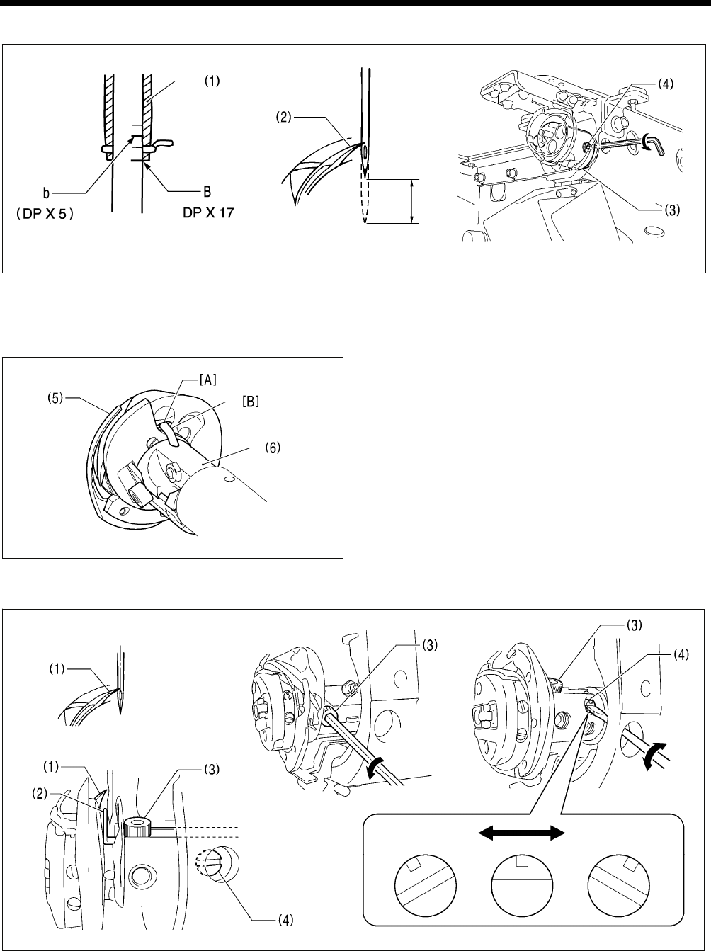
11. STANDARD ADJUSTMENTS
BAS-342G PS
57
11-4. Adjusting the needle bar lift amount
Turn the machine pulley to raise the needle bar from the lowest position until the lowest reference line on the needle bar
(reference line B) is aligned with the lower edge of the needle bar bush (1), and then adjust the two set screws (4) of the
rotary hook joint (3) so that the rotary hook tip (2) is aligned with the center of the needle.
* If using a DP X 5 needle, use the second reference line from the top of the needle bar (reference line b).
NOTE:
When installing the rotary hook joint, install using the set
screws so that the oil inlet [A] in the rotary hook (5) is
aligned with the oil inlet [B] in the rotary hook joint
assembly (6).
11-5. Adjusting the driver needle guard
Turn the machine pulley to align the tip of the rotary hook (1) with the center of the needle, and then loosen the bolt (3) and
turn the needle guard adjusting shaft (4) to adjust so that the driver needle guard (2) is touching the needle.
NOTE:
If it crosses the needle more than necessary, it will place a load on the needle, or it may cause poor thread tension.
Furthermore, if it does not cross the needle at all, the tip of the rotary hook (1) will interfere with the needle and skipped
stitches may occur.
2554Q 1880B 2768B
2211B
1913B
Center of needle
Becomes further
away from needle
Becomes closer
to needle
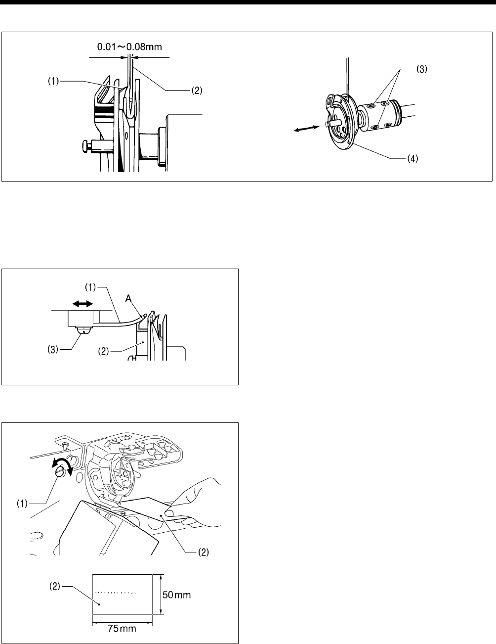
11. STANDARD ADJUSTMENTS
BAS-342G PS 58
11-6. Adjusting the needle clearance
Turn the machine pulley to align the rotary hook tip (1) with the center of the needle (2), and then loosen the two set screws
(3) and move the rotary hook (4) forward or back to adjust so that the clearance between the needle (2) and the rotary hook
tip (1) is 0.01 − 0.08 mm.
11-7. Adjusting the inner rotary hook and hook stopper overlap
Loosen the two screws (3) to adjust so that the tip of the
hook stopper (1) does not protrude past edge A of the inner
rotary hook (2).
11-8. Adjusting the rotary hook lubrication amount
Turn the adjusting screw (1) to adjust the lubrication
amount.
* Adjust so that approximately 10 drops of oil are released
when the sewing machine is run at a speed of 2,700
sti/min for three cycles to sew about 150 stitches. Use
Kraft paper (2) or similar to catch the oil drops. As a
guide, the optimum position can be obtained if the
adjusting screw (1) is tightened as much as possible and
then loosened about one turn.
• If the adjusting screw (1) is turned clockwise, the
lubrication amount becomes smaller.
• If the adjusting screw (1) is turned counterclockwise,
the lubrication amount becomes greater.
1883B
Q
1884B
1908B
More oil
Less oil
2769B
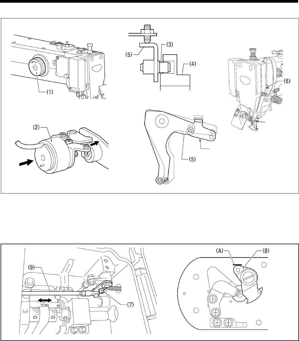
11. STANDARD ADJUSTMENTS
BAS-342G PS
59
11-9. Adjusting the position of the movable knife
1. Open the top cover and tilt back the machine head.
2. Turn the pulley (1) by hand to lower the needle bar to its lowest position, and push the thread trimmer solenoid (2) as far
as it will go.
3. With the collar (3) inserted into the groove of the thread trimmer cam (4), turn the pulley (1) by hand to set the driving lever
(5) to the reverse position (when the thread take-up (6) is close to its lowest position).
4. Loosen the bolt (7).
5. Move the thread trimming rod H (9) forward or back to adjust so that the ridge line on the movable knife (8) and reference
line (A) on the needle plate are aligned.
6. After tightening the bolt (7), check the above position once more.
<View from side of thread trimmer cam>
Reverse position
5255Q 2908B
5232Q 2921B
2574B
2909B 2210B
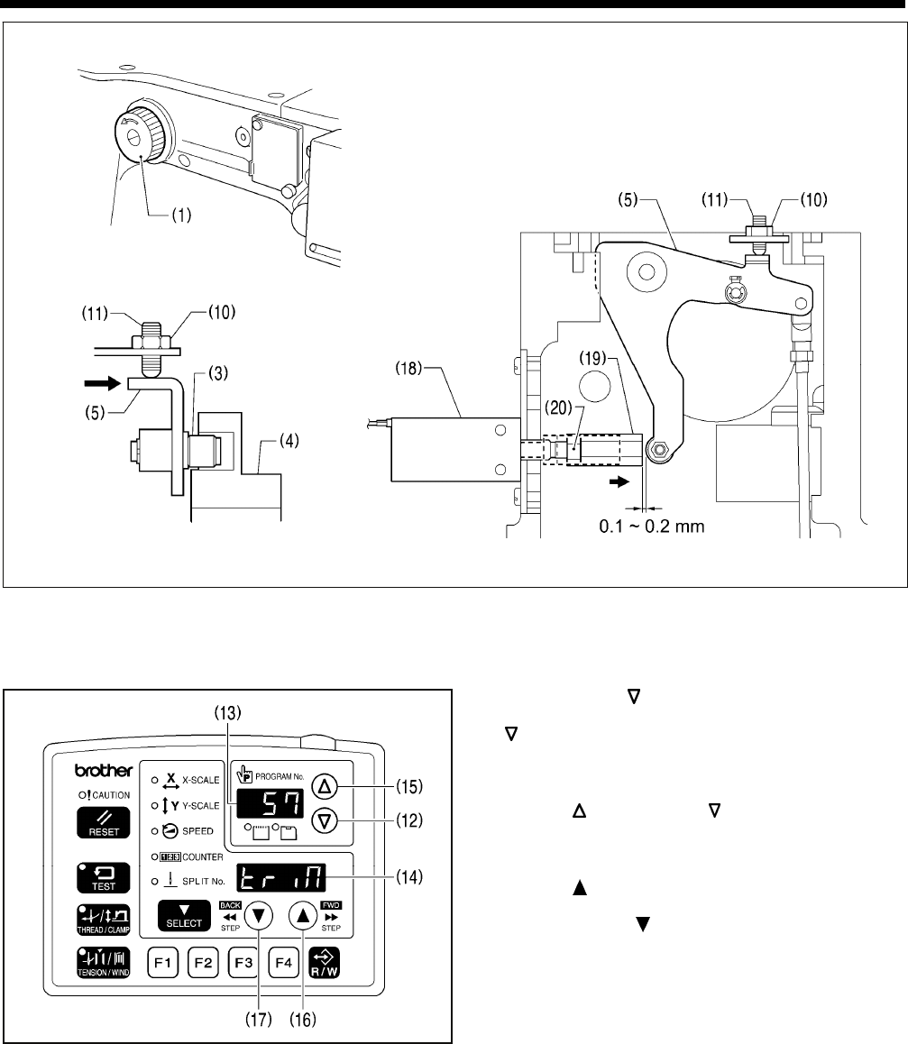
11. STANDARD ADJUSTMENTS
BAS-342G PS 60
7. Turn the pulley (1) by hand to move the needle bar to its lowest position.
8. Loosen the nut (10) until the thread trimmer roller (3) is within the groove in the thread trimmer cam (4). After this, tighten
the set screw (11) until the thread trimmer roller (3) is touching the inside of the groove in the thread trimmer cam (4) and
then turn it back in the counterclockwise direction by approximately 1/4 of a turn. Then tighten the nut (10).
9. While pressing the key (12), turn on the power switch.
* After the model name is displayed, keep pressing the
key (12) until the buzzer sounds.
The check code will appear in the PROGRAM No.
display (13), and the abbreviation for the output name
will appear in the menu display (14).
10. Press the key (15) or the key (12) to select check
code 57.
* Refer to the Service Manual for details on other
check codes.
11. Press the key (16) to turn on the thread trimming air
cylinder (18).
* If you press the key (17), the thread trimming air
cylinder (18) will turn off.
12. While the thread trimming air cylinder (18) is turned on,
loosen the nut (20) and adjust the position of the thread
trimming bar (19) so that the clearance between the
thread trimming bar (19) and the driving lever (5) is 0.1
to 0.2 mm.
13. Loosen the nut (10) once more, and then turn the set screw (11) a further 1/4 of a turn in the counterclockwise direction.
14. Tighten the nut (10), and then check that the collar (3) is not touching the inside of the groove in the thread trimmer cam
(4). In addition, push the driving lever (5) by hand toward the thread trimmer cam (4) until the collar (3) touches the
groove of the thread trimmer cam (4), and then check that the driving lever (5) returns smoothly to its original position
when it is released.
15. Turn off the power switch.
(Continued on next page)
2911B 2913B
2910B
2912B
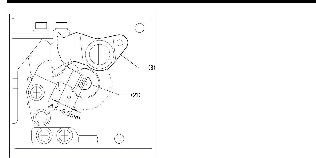
11. STANDARD ADJUSTMENTS
BAS-342G PS
61
16. Check that there is a gap of about 8.5 – 9.5 mm
between the tip of the movable knife (8) and the center
of the hole in the needle hole plate (21) when there is
still play between the parts.
2917B
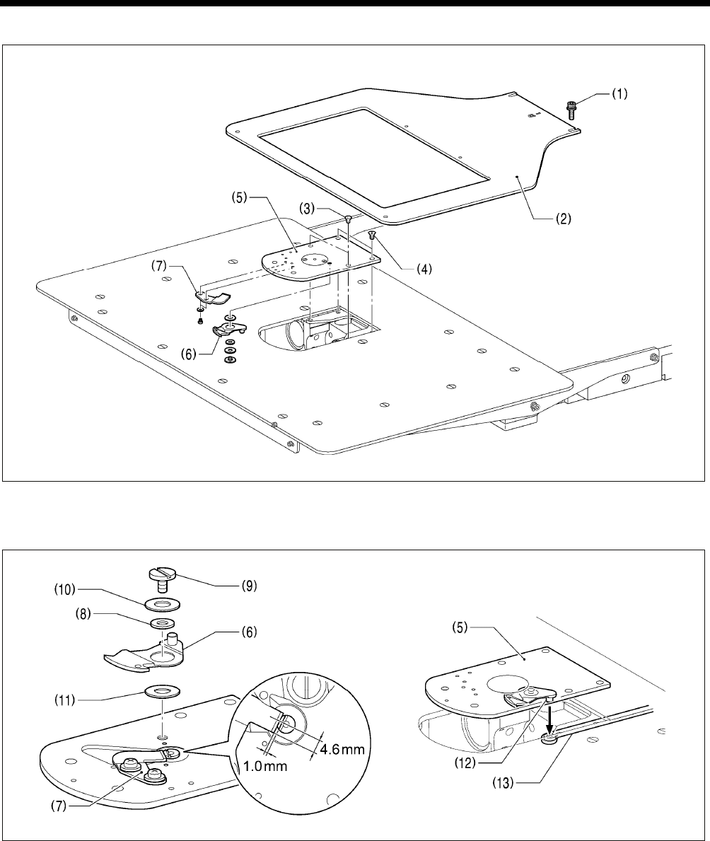
11. STANDARD ADJUSTMENTS
BAS-342G PS 62
11-10. Replacing the movable and fixed knives
1. Loosen the two bolts (1) and then remove the feed plate (2).
2. Open the shuttle race cover, remove the two screws (3) and the two flat screws (4), and then remove the needle plate (5).
3. Remove the movable knife (6) and the fixed knife (7).
4. Install the new fixed knife (7) in the position shown in the illustration.
5. Apply grease to the outside of the collar (8) and to the shoulder screw (9), and then install the new movable knife (6)
together with the thrust washer (10) and the movable knife spacer (11).
6. Check that the movable knife (6) and fixed knife (7) cut the thread cleanly. Replace the movable knife spacer with
accessory spacers (t=0.2, 0.3, 0.4) so that the knives trim the thread accurately.
* If the knife pressure is too weak and the thread is not completely cut, use a thinner movable knife spacer.
* If the knife pressure is too strong and the movable knife (6) turns stiffly, use a thicker movable knife spacer.
7. Apply grease to the pin (12), place it into the movable knife connecting plate (13), and install it to the needle plate (5).
8. Check that the needle is aligned with the center of the needle hole.
2771B
2772B
1890B
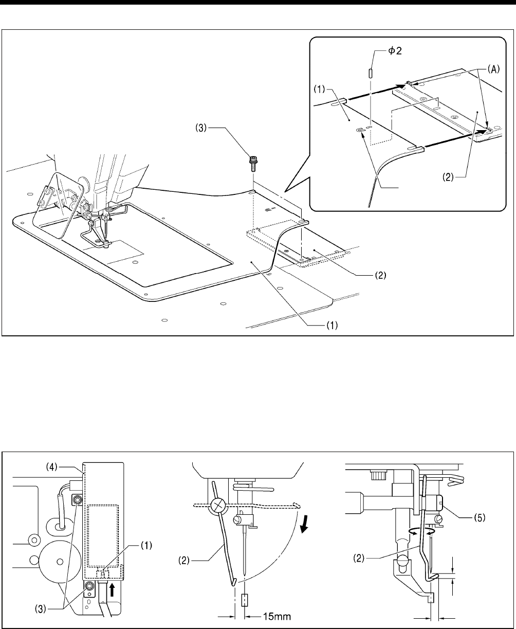
11. STANDARD ADJUSTMENTS
BAS-342G PS
63
11-10-1. Installing the feed plate
NOTE:
Install the feed plate so that the surface with the index mark is facing upward.
Place the rear edge of the feed plate (1) against the projection of base plate Y (2) (shaded section (A)) and use a 2 mm
diameter pin (such as a needle) to align the hole in the feed plate (1) with the hole in base plate Y (2); then tighten the two
bolts (3).
11-11. Adjusting the thread wiper
1. Loosen the two screws (3) and shift the entire solenoid setting plate (4) up or down to adjust so that the thread wiper (2) is
15 mm in front of the needle center when the plunger (1) of the thread wiper solenoid is driven to the full stroke.
2. Loosen the screw (5) and adjust the position of the thread wiper (2) so that the distance from the thread wiper to the tip of
the needle is approximately 2 mm and the tip of the thread wiper (2) is approximately 3 mm from the center of the needle
when the thread wiper (2) passes below the needle during operation.
NOTE: Check that the thread wiper (2) does not touch the finger guard.
Index mark
2773B
Approx. 2mm
Approx. 3mm 1893B 1892B5007Q
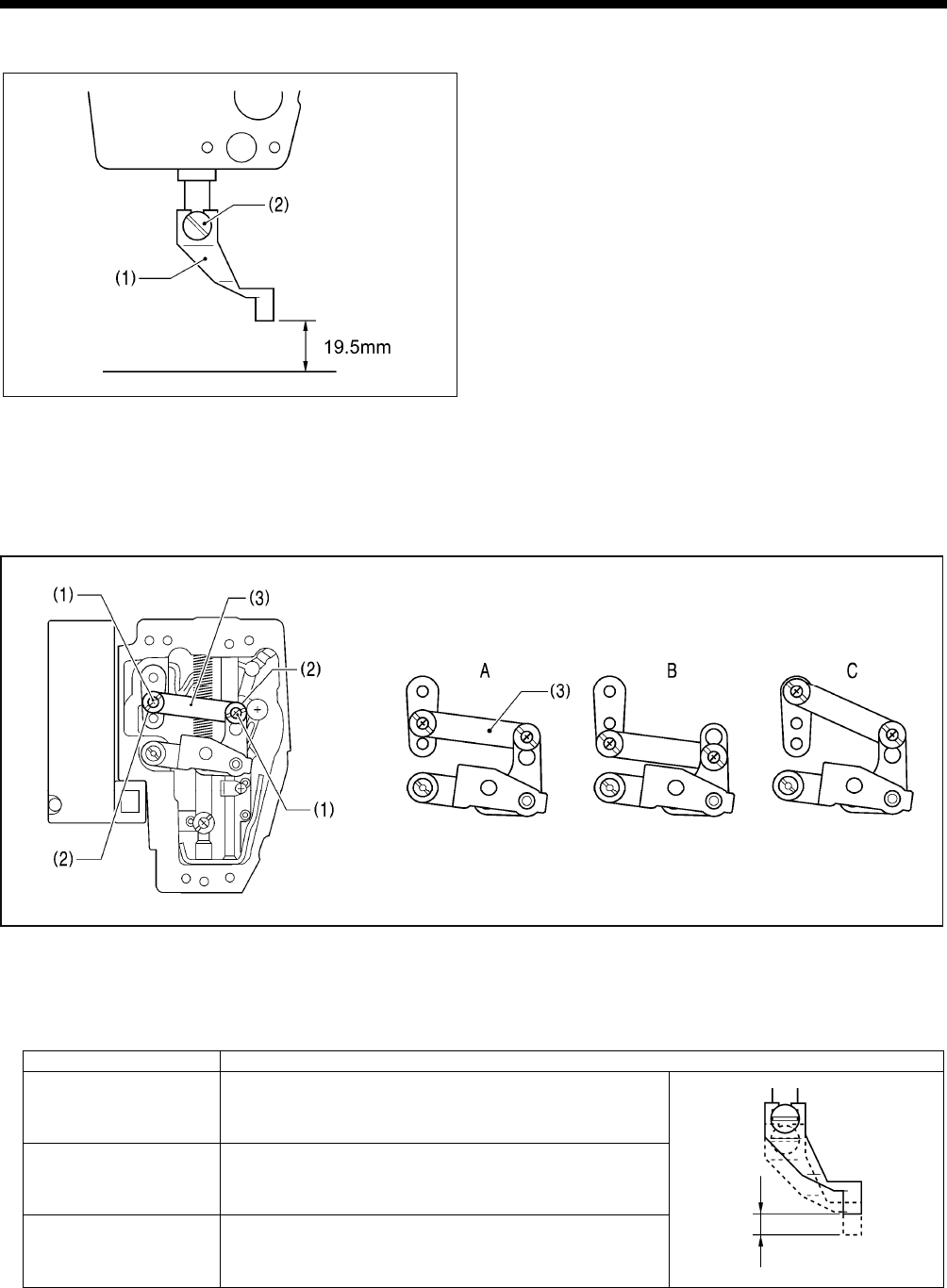
11. STANDARD ADJUSTMENTS
BAS-342G PS 64
11-12. Presser foot installation position
Install the intermittent presser foot (1) with the screw (2) so
that the distance from the bottom of the intermittent presser
foot to the top of the needle plate is 19.5 mm when the
sewing machine is stopped and the intermittent presser foot
(1) is raised.
11-13. Changing the intermittent stroke
The intermittent stroke can be adjusted to within 2 − 10 mm by adjusting the position of the stepping clamp connecting rod
and changing the installation position of stepping clamp link A.
<Changing the installation position of stepping clamp link A>
1. Remove the face plate.
2. Remove the two screws (1) and the two shoulder screws (2), and then remove stepping clamp link A (3).
3. Change the installation position for stepping clamp link A (3) to either A, B or C above.
If the position of the stepping clamp connecting rod is adjusted as described in the following at any one of the installation
positions, the adjustment range for the intermittent stroke will as given in the following table. (Refer to the next page.)
Installation position Intermittent stroke range
A 2 − 4.5mm
B 4.5 − 10mm
C 0 mm (Presser foot does not move up and down)
5012Q
4049M
1894B
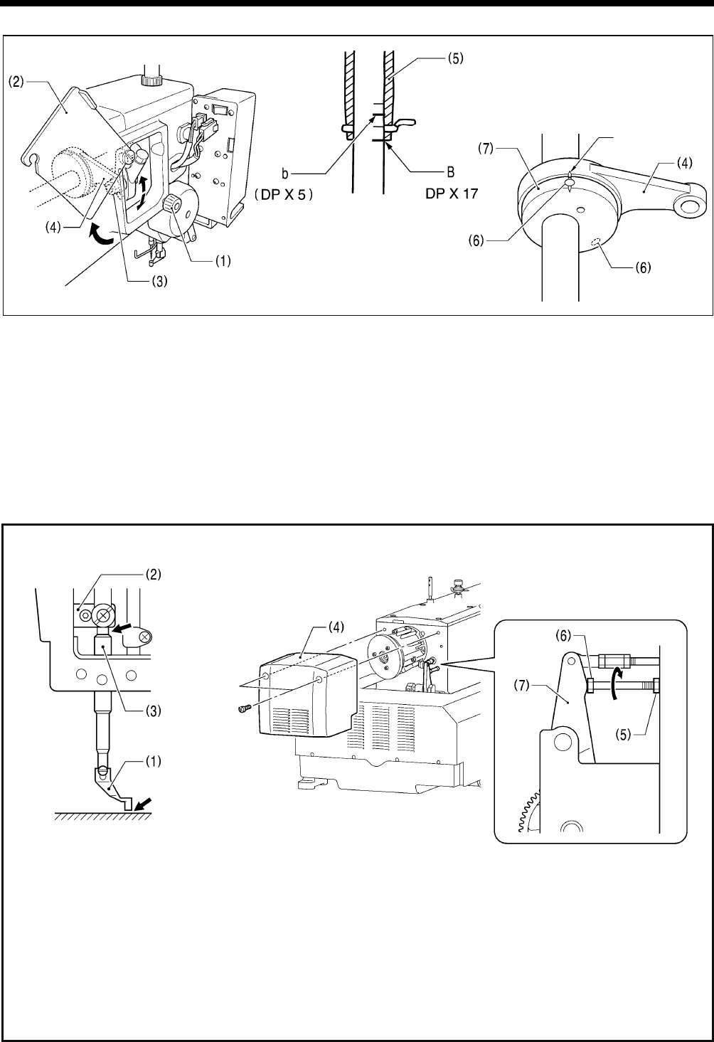
11. STANDARD ADJUSTMENTS
BAS-342G PS
65
<Stepping clamp connecting rod position adjustment>
1. Loosen the screw (1), and then open the cover (2).
2. Loosen the nut (3), and then adjust the position of the stepping clamp connecting rod (4).
• When the stepping clamp connecting rod (4) is raised, the intermittent stroke will increase.
• When the stepping clamp connecting rod (4) is lowered, the intermittent stroke will decrease.
Next, adjust the needle bar and presser foot timing.
3. Turn the machine pulley to raise the needle bar from the lowest position until the lowest reference line on the needle bar
(reference line B) is aligned with the lower edge of the needle bar bush (5).
(If using a DP x 5 needle, align with the second reference line from the top (reference line b).)
4. Open the top cover and loosen the two set screws (6).
5. Align the index marks on the stepping clamp cam (7) and the stepping clamp connecting rod (4), and then tighten the set
screws (6).
Check the following after changing the intermittent stroke.
1. With the intermittent presser foot (1) lowered, turn the pulley to move the intermittent presser foot (1) to its lowest
position.
2. Check that the presser foot (1) does not touch the needle plate and that the presser bar clamp (2) does not touch the
presser bar bush (3).
<If they are touching>
Remove the motor cover (4).
Loosen the nut (5), and turn the bolt (6) until it is pressing against the intermittent drive lever (7), and then adjust until the
two points mentioned above are not touching.
5014Q
5016Q 4051M
Needle plate
Index mark
5015Q
4050M
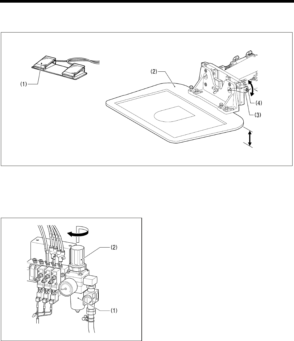
11. STANDARD ADJUSTMENTS
BAS-342G PS 66
11-14. Adjusting the work clamp lift amount
The maximum lift amount for the work clamp (2) is 30 mm above the top of the needle plate.
1. Turn on the air, and then turn on the power switch.
2. Depress the work clamp switch (1) to raise the work clamp (2).
3. Loosen the two bolts (4) of the work clamp lifter lever (3), and then move the work clamp lifter lever (3) up or down to
adjust the lift amount.
11-15. Adjusting the air pressure
Lift up the handle (2) of the regulator (1) and then turn it to
adjust the air pressure to 0.5 MPa.
After adjustment is complete, push the handle (2)
downward to lock it.
4052M
5018Q
Max. 30mm
2748B
12. TABLE OF ERROR CODES
BAS-342G PS
67
12. TABLE OF ERROR CODES
DANGER
Wait at least 5 minutes after turning off the power switch and disconnecting the power cord from the wall outlet
before opening the cover of the control box. Touching areas where high voltages are present can result in severe
injury.
If a malfunction should occur with the sewing machine, a buzzer will sound and an error code will appear in the display
window. Follow the remedy procedure to eliminate the cause of the problem.
Switch-related errors
Code Cause and remedy
E010 Stop switch was pressed. Press the RESET key to clear the error.
E011 Stop switch was pressed. Press the RESET key to clear the error.
Press the key to move the work clamp so that you can continue sewing.
E015 The stop switch was still being pressed, or there is a problem with the stop switch connection.
Turn off the power, and then check that connector P13 on the main P.C. board is properly connected.
E016 Problem with the stop switch connection.
Turn off the power, and then check that connector P13 on the main P.C. board is properly connected.
E025
The power was turned on while the start switch was still being depressed, or the start switch was depressed
without the work clamp being lowered.
If the power has been turned on while the start switch was still depressed, turn off the power and check the start
switch.
If the start switch was depressed without lowering the work clamp, depress the work clamp switch to lower the
work clamp.
E035 The work clamp switch is depressed.
Turn off the power, and then check the work clamp switch.
E036 A foot switch that does not match specifications is connected, or work clamp mode has not been set correctly.
Use a foot switch that matches specifications, or initialize the memory switch settings.
E050
Machine head tilting was detected after the power was turned on.
Turn off the power, and then return the machine head to its original position.
Check that connector P9 on the main P.C. board is properly connected.
E051 Machine head tilting was detected while the sewing machine was operating.
Turn off the power, and then check that connector P9 on the main P.C. board is properly connected.
E055
Machine head tilting was detected when the power was turned on.
Turn off the power, and then return the machine head to its original position.
Check that connector P9 on the main P.C. board is properly connected.
E065 An operation panel key was still being pressed when the power was turned on, or key is faulty.
Turn off the power and check the operation panel.
Upper shaft motor-related errors
Code Cause and remedy
E110 Needle up stop position error.
Turn the machine pulley until the point where the error display disappears.
E111 Upper shaft did not stop at the needle up stop position when the sewing machine stopped.
Turn the machine pulley until the point where the error display disappears.
E120 Needle drop signal could not be detected.
Turn off the power, and then check the synchronizer connection.
E121
Thread trimming was not completed.
Turn off the power, and then check if the cutting edges of the fixed knife and movable knife are damaged or worn,
and if there are any problems with the thread trimming air cylinder.
(Continued on next page)

12. TABLE OF ERROR CODES
BAS-342G PS 68
Code Cause and remedy
E130
Sewing machine motor stopped due to a problem, or synchronizer is faulty.
Turn off the power, and then turn the machine pulley and check if the sewing machine has locked up.
Check that connectors P4 and P5 on the power supply motor P.C. board are properly connected.
E131
Synchronizer is faulty.
Turn off the power, and then check that connector P5 on the power supply motor P. C. board is properly
connected.
E132
Problem detected with sewing machine motor operation.
Turn off the power, and then check that connector P4 on the power supply motor P.C. board is properly
connected.
E133
Sewing machine motor stopping position is incorrect.
Turn off the power, and then check that connector P5 on the power supply motor P.C. board is properly
connected.
E150
Sewing machine motor is overheating, or temperature sensor is faulty.
Turn off the power, and then check the sewing machine motor.
(When sewing data with a small number of stitches (15 stitches or less) is sewn repeatedly (short cycle
operation), the upper shaft motor may overheat and the "E150" error code may be generated.)
Feed mechanism-related errors
Code Cause and remedy
E200
X-feed motor home position cannot be detected.
Problem with X -feed motor or poor X home position sensor connection.
Turn off the power, and then check that connector P10 on the PMD P.C. board and connector P20 on the main
P.C. board are properly connected.
E201 X-feed motor stopped due to a problem.
Turn off the power, and then check if there are any problems in the X-feed direction.
E202 Problem with X-feed motor or Y-feed motor home position adjustment data.
Re-adjust the home position.
E204 X feed motor stopped abnormally during sewing.
Turn off the power, and then check if there are any problems in the X-feed direction.
E205 X feed motor stopped abnormally while moving to the sewing start position.
Turn off the power, and then check if there are any problems in the X-feed direction.
E206 X feed motor stopped abnormally during test feeding.
Turn off the power, and then check if there are any problems in the X-feed direction.
E207 X feed motor stopped abnormally during programming.
Turn off the power, and then check if there are any problems in the X-feed direction.
E210
Y-feed motor home position cannot be detected.
Problem with Y-feed motor or poor Y home position sensor connection.
Turn off the power, and then check that connector P8 on the PMD P.C. board and connector P4 on the main P.C.
board are properly connected.
E211 Y-feed motor stopped due to a problem.
Turn off the power, and then check if there are any problems in the Y-feed direction.
E214 Y feed motor stopped abnormally during sewing.
Turn off the power, and then check if there are any problems in the Y-feed direction.
E215 Y feed motor stopped abnormally while moving to the sewing start position.
Turn off the power, and then check if there are any problems in the Y-feed direction.
E216 Y feed motor stopped abnormally during test feeding.
Turn off the power, and then check if there are any problems in the Y-feed direction.
E217 Y feed motor stopped abnormally during programming.
Turn off the power, and then check if there are any problems in the Y-feed direction.
Work clamp-related errors
Code Cause and remedy
E300
Work clamp home position cannot be detected.
Problem with work clamp motor or poor work clamp home position sensor connection.
Turn off the power, and then check that connector P3 on the PMD P.C. board and connector P5 on the main P.C.
board are properly connected.
E301 Intermittent presser foot raised or lowered position cannot be detected.
Turn off the power, and then check if there are any problems in the intermittent presser foot vertical direction.
E303 Problem with work clamp motor home position adjustment data.
Re-adjust the home position.

12. TABLE OF ERROR CODES
BAS-342G PS
69
Communication and memory-related errors
Code Cause and remedy
E401
Connection communication error with power supply motor P. C. board detected when power was turned on.
Turn off the power, and then check that connector P6 on the power supply motor P.C. board and connector P17
on the main P.C. board are properly connected.
E402 Communication error with programmer detected when power is turned on.
Turn off the power, and then check that connector P7 on the main P.C. board is properly connected.
E403 Connection error with PMD P. C. board detected when power was turned on.
Turn off the power, and then check that connector P1 on the PMD P.C. board is properly connected.
E410 Communication error with main P. C. board detected.
Turn off the power, and then turn it back on again.
E411 Communication error with power supply motor P. C. board detected.
Turn off the power, and then turn it back on again.
E412 Communication error with programmer detected.
Turn off the power, and then turn it back on again.
E413 Communication error with PMD P. C. board detected.
Turn off the power, and then turn it back on again.
E420 No CF card is inserted.
E421 Program contents are incorrect and cannot be used, or no data.
Check that the CF card or floppy disk contains data with this program number.
E422 Error occurred while reading the CF card or floppy disk.
Check the data on the CF card or floppy disk.
E424
Insufficient free space on the CF card, or data cannot be written to the floppy disk.
Use a different CF card.
Check if the floppy disk is write-protected and if it has enough free space.
E425
Error occurred while writing to the CF card or floppy disk.
Use the specified type of CF card.
Check if the floppy disk is write-protected and if it has enough free space.
E426 R/W key has not been pressed.
Press the R/W key to load the data.
E427
CF card or floppy disk does not contain any data with this program number.
Check the program number.
Data that has already been loaded into internal memory can be used without having to press the R/W key again.
E430 Data cannot be backed up to main P.C. board.
Turn off the power, and then turn it back on again.
E440 Data memory error on main P.C. board.
Turn off the power, and then turn it back on again.
E450 Model selection cannot be read from the machine head memory.
Turn off the power and check that connector P3 on the power supply motor P.C. board is properly connected.
E451 Data cannot be backed up to machine head memory.
Turn off the power, and then turn it back on again.
E452
Machine head memory is not connected.
Turn off the power, and then check that connector P3 on the power supply motor P.C. board is properly
connected.
E474 Internal memory is full and copying is not possible.
Clear the sewing data.

12. TABLE OF ERROR CODES
BAS-342G PS 70
Data editing-related errors
Code Cause and remedy
E500 The enlargement ratio setting caused the sewing data to extend outside the sewing area.
Set the enlargement ratio again.
E501 Sewing data that exceeds the sewing machine's sewing area was loaded.
Check the size of the sewing data.
E502 The enlargement ratio caused the data pitch to exceed the maximum pitch of 12.7 mm.
Set the enlargement ratio again.
E510 Invalid code in sewing data.
Reload the data from the CF card or floppy disk.
E511 No end code has been input into sewing data.
Input an end code, or change the program number.
E512 Number of stitches exceeds allowed maximum.
E520 Extended option output number already exists. Change the extended option output number.
If not using the extended option output, initialize the data to clear the extended option output data.
E530 Changing program number is prohibited.
P.C. board-related errors
Code Cause and remedy
E700 Abnormal rise in power supply voltage.
Turn off the power and check the input voltage.
E701 Abnormal rise in sewing machine motor drive voltage.
Turn off the power, and then check the voltage.
E705 Abnormal drop in power supply voltage.
Turn off the power and check the input voltage.
E710 Abnormal current detected in sewing machine motor.
Turn off the power, and then check if there are any problems with the sewing machine.
E711 Abnormal current detected in X-feed motor.
Turn off the power, and then check if there are any problems in the X-feed direction.
E712 Abnormal current detected in Y-feed motor.
Turn off the power, and then check if there are any problems in the Y-feed direction.
E713
Abnormal current detected in work clamp motor.
Turn off the power, and then check if there are any problems with the X-feed mechanism, Y-feed mechanism or
work clamp lifter.
E730 External error input (AIRSW) detected.
Turn off the power, and then check the air pressure.
E740
Control box cooling fan does not operate.
Turn off the power, and then check if the cooling fan is blocked with scraps of thread.
Check that connector P22 on the main P.C. board is properly connected.
E741
X-feed motor cooling fan does not operate.
Turn off the power, and then check if the cooling fan is blocked with scraps of thread.
Check that connector P10 on the main P.C. board is properly connected.
E742
Y-feed motor cooling fan does not operate.
Turn off the power, and then check if the cooling fan is blocked with scraps of thread.
Check that connector P10 on the main P.C. board is properly connected.
If an error code that is not listed above appears or if carrying out the specified remedy does not solve the problem,
contact the place of purchase.
13. TROUBLESHOOTING
BAS-342G PS
71
13. TROUBLESHOOTING
• Please check the following points before calling for repairs or service.
• If the following remedies do not fix the problem, turn off the power switch and consult a qualified technician or the place of
purchase.
CAUTION
Turn off the power switch and disconnect the power cord before carrying out troubleshooting.
If the foot switch is depressed by mistake, the sewing machine might start operating and injury could result.
Items with a “*” in the “Reference” column should only be checked by a qualified technician.
Problem Cause Remedy Reference
Work clamp moves stiffly. Apply a suitable amount of grease to the
sliding parts of the work clamp. *
Work clamp does not
lift.
Work clamp does not
drop. Air tube of air cylinder is bent or
damaged.
Straighten the bend in the tube or
replace the tube. *
Work clamp lift amount
is incorrect.
Work clamp lifter lever position is
incorrect.
Adjust the position of the work clamp
lifter lever. P. 66
Work clamp does not
lift to the maximum
height.
Cylinder joint position is incorrect. Adjust the position of the cylinder joint. *
Adjust the height of the thread wiper. P. 63
The thread wiper is obstructing the
needle.
Adjust the stroke of the thread wiper. P. 63
Thread wiper does
not operate correctly.
Thread wiper position is incorrect. Adjust the stroke of the thread wiper. P. 63
Lower thread winds
to one side.
Bobbin winder tension assembly height
is incorrect.
Adjust the height of the bobbin winder
tension assembly. P. 22
Lower thread winding
amount is incorrect. Bobbin presser position is incorrect. Adjust the position of the bobbin presser. P. 22
Stitches being skipped at the sewing
start. Refer to "Skipped stitches occur". P. 72
Thread slips out of
the needle.
Upper thread trailing length is uneven. Adjust the sub tension. P. 24
Thread unravelling at
sewing start. Rotary hook pulls the upper thread at the
sewing start.
Use the programmer to reduce the
intermittent presser foot height so that
the upper thread is pressed by the
intermittent presser foot at the 1st stitch.
*

13. TROUBLESHOOTING
BAS-342G PS 72
Problem Cause Remedy Reference
Upper thread tension is too strong. Adjust the upper thread tension. P. 24
Needle is incorrectly installed. Install the needle correctly. P. 19
Thread is too thick for the needle. Select a thread that matches the needle. P. 24
Thread take-up spring tension and
height are incorrect.
Adjust the tension and height of the
thread take-up spring. P. 55
Damage or burring of the rotary hook,
needle hole plate, needle or thread path. Repair or replace the problem part. *
Thread breaking from heat
(Synthetic thread). Use a needle cooler. P. 20
Thread is threaded incorrectly. Thread the thread correctly. P. 20
Upper thread breaks.
Damage to the hook stopper. Buff the hook stopper to remove the
damage, or replace the hook stopper. *
Lower thread tension is too strong. Adjust the lower thread tension. P. 24
Lower thread breaks.
Damage to the needle hole plate or
bobbin case. Repair or replace the problem part. *
Clearance between needle and rotary
hook tip is too great. Adjust the needle clearance. P. 58
Needle and rotary hook timing is
incorrect. Adjust the needle bar lift amount. P. 57
The driver needle guard is covering the
needle more than necessary. Adjust the driver needle guard. P. 57
Needle is bent. Replace the needle.
Needle is incorrectly installed. Install the needle correctly. P. 19
Skipped stitches occur.
Intermittent height of intermittent presser
foot is too high.
Adjust the intermittent height of the
intermittent presser foot. P. 32
Adjust the needle clearance. P. 58
Clearance between needle and rotary
hook tip is too great.
Adjust the needle bar lift amount. P. 57
Needle is bent. Replace the needle.
Needle deflection.
Select a needle that is suitable for the
sewing conditions.
Reduce the sewing speed.
P. 24
P. 30
Needle is broken.
Needle is too thin. Select a needle that is suitable for the
sewing conditions. P. 24
Thread take-up spring tension and
height are incorrect.
Adjust the tension and height of the
thread take-up spring. P. 55
Thread jamming.
Needle and rotary hook timing is
incorrect. Adjust the needle bar lift amount. P. 57

13. TROUBLESHOOTING
BAS-342G PS
73
Problem Cause Remedy Reference
Movable knife is not cutting cleanly. Replace with a new one. P. 62
Fixed knife is not cutting cleanly. Sharpen the fixed knife or replace it
with a new one. P. 62
Adjust the position of the movable
knife. P. 59
Movable knife is not picking up the
upper thread.
Adjust the needle bar lift amount. P. 57
Movable knife is not picking up the
upper thread because the last stitch is
being skipped.
Refer to "Skipped stitches occur". P. 72
Movable knife position is incorrect. Adjust the position of the movable
knife. P. 59
Sub tension is too weak. Turn the sub tension nut to adjust the
tension. P. 24
Thread trimming air cylinder speed is
too slow.
Adjust the speed of the thread trimming
air cylinder. P. 11
Upper thread is not
trimmed.
Thread trimming air cylinder operation
timing is too delayed.
Advance the operation timing for the
thread trimming air cylinder. P. 35
Incorrect tightening of the upper thread. Adjust the upper thread tension. P. 24
Poor stitch finish on
underside of material.
Upper thread trailing length is uneven. Adjust the sub tension. P. 24
Upper thread tension is too weak. Adjust the upper thread tension. P. 24
Lower thread tension is too weak. Adjust the lower thread tension. P. 24
Thread take-up spring tension and
height are incorrect.
Adjust the tension and height of the
thread take-up spring. P. 55
Position of arm thread guide R is
incorrect.
Adjust the position of arm thread guide
R. P. 56
Intermittent height of intermittent
presser foot is too low.
Adjust the intermittent height of the
intermittent presser foot. P. 32
Upper thread does not release
correctly from hook stopper.
Adjust the overlapping amount for the
inner rotary hook and hook stopper. P. 58
Feed timing is too fast. Retard the feed timing. *
Select the correct needle hole plate. *
Smooth the thread path. *
Select the correct intermittent presser
foot. *
Upper thread forms the seam poorly.
Increase the thickness of the feed
plate. *
Incorrect tightening of
the thread.
Thread scraps and dust in rotary hook. Clean away the thread scraps and
dust. P. 53

13. TROUBLESHOOTING
BAS-342G PS 74
Problem Cause Remedy Reference
Needle is too thin. Replace the needle with one with a
higher count.
Incorrect tightening of
the thread.
Damage to the hook stopper. Buff the hook stopper to remove the
damage, or replace the hook stopper. *
Thread take-up spring tension and
height are incorrect.
Adjust the tension and height of the
thread take-up spring. P. 55
Sub tension is too weak. Turn the sub tension nut to adjust the
tension. P. 24
Upper thread trailing
length is irregular.
Fixed knife is not cutting cleanly. Sharpen the fixed knife or replace it
with a new one. P. 62
Thread take-up spring tension is too
strong.
Adjust the tension of the thread take-up
spring. P. 55
Lower thread is
protruding from the top
of the material.
Insufficient thread take-up amount. Adjust the position of arm thread guide
R. P. 56
Lower thread tension is too weak. Adjust the lower thread tension. P. 24
Lower thread is threaded incorrectly. Pass the lower thread through the
window of the inner rotary hook. P. 23
Sewing speed is too high. Reduce the sewing speed. P. 30
Needle is incorrectly installed. Install the needle correctly. P. 19
Select the correct intermittent presser
foot. *
Upper thread position is incorrect. Grind the cylinder of the intermittent
presser foot so that it does not touch
the thread. *
Hitch stitch sewing
range is too great.
Needle is shaking. Replace the needle with one with a
higher count.
Thread trailing length
underneath the material
is too short.
Fixed knife position is too close to the
needle hole plate.
Install the fixed knife in the correct
position. P. 62
Check if the safety switch cord is
disconnected. P. 12
Adjust the position of the safety switch. P. 18
Sewing machine does
not operate when the
power is turned on and
the foot switch is
depressed. Safety switch does not work.
If the safety switch is malfunctioning,
replace it with a new one. *
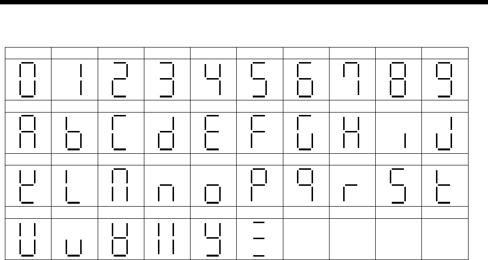
14. 7-SEGMENT DISPLAY
75 BAS-342G PS
14. 7-SEGMENT DISPLAY
0 1 2 3 4 5 6 7 8 9
A B C D E F G H I J
K L M N O P Q R S T
U V W X Y Z

MEMO
76
BAS-342G PS
INSTRUCTION MANUAL
© 2010 Brother Industries, Ltd. All Rights Reserved.
This is the original instructions.
BAS-342G PS
SB2118-001 E
2010.11. B (1)
