Pdf EXT ADA LAN Manual
2018-03-29
: Manual Pdf Ext-Ada-Lan Manual pdf_EXT-ADA-LAN_manual EXT-ADA-LAN-RX products
Open the PDF directly: View PDF ![]() .
.
Page Count: 126 [warning: Documents this large are best viewed by clicking the View PDF Link!]
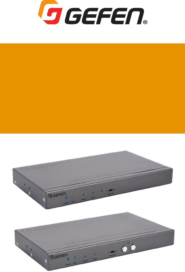
EXT-ADA-LAN-TX
EXT-ADA-LAN-RX
User Manual
Version A2
Gen 2.0
Digital & Analog Audio
over IP

2
Important Safety Instructions
1. Read these instructions.
2. Keep these instructions.
3. Heed all warnings.
4. Follow all instructions.
5. Do not use this product near water.
6. Clean only with a dry cloth.
7. Do not block any ventilation openings. Install in accordance with the manufacturer’s
instructions.
8. Do not install or place this product near any heat sources such as radiators, heat registers,
9. Do not defeat the safety purpose of the polarized or grounding-type plug. A polarized
plug has two blades with one wider than the other. A grounding type plug has two blades
and a third grounding prong. The wide blade or the third prong are provided for your
-
ment of the obsolete outlet.
10. Protect the power cord from being walked on or pinched particularly at plugs,
convenience receptacles, and the point where they exit from the apparatus.
11.
12. To reduce the risk of electric shock and/or damage to this product, never handle or touch
this unit or power cord if your hands are wet or damp. Do not expose this
product to rain or moisture.
13. Unplug this apparatus during lightning storms or when unused for long periods of time.
14.
apparatus has been damaged in any way, such as power-supply cord or plug is
damaged, liquid has been spilled or objects have fallen into the apparatus,
the apparatus has been exposed to rain or moisture, does not operate normally,
or has been dropped.
15. Batteries that may be included with this product and/or accessories should never be
according to the instructions.


4
Contact Us
Technical Support
1-707-283-5900 1-800-472-5555
Email
support@gefen.com
Web
http://www.gefen.com
Mailing Address
Gefen
All trademarks are the property of their respective owners.
packaging, and any accompanying documentation without prior notice.

5
Operating Notes
This product uses UL-Listed power supplies
Important
•
•
• In a Multi-Format system, when using HDCP-encrypted content, only HDMI &
DisplayPort™ inputs & outputs can accept or display content.
•
•
•
•
controlling the operation of an AV-over-IP network using these products. Alternatively,
™
•
•
• If
Network Cable Diagram (page 123 for details.

6
Operating Notes
Licensing
respective open source licenses:
• jQuery
•

7
Features
•
•
•
capable Gefen AV over IP products.
•
•
•
• Enhanced API for added functionality with third-party control systems
• Built-in web interface, Telnet, and UDP
•
gefen.com
•
on the network bandwidth and number of ports on your network switch
•
through a standard PoE-enabled IP network switch, without the need for external power supplies
• Two-port Gigabit Ethernet switch built into the Receiver unit
•
•
•
1U-GRY
•
•
Features

8
Packing List
Packing List - Sender unit
possible.
Packing List - Receiver unit
The following items are included in the Receiver Unit package. If any of these items are not
possible.

9
Table of Contents
Introduction ....................................................................................................................11
............................................................................................................................. 11
Receiver Unit ......................................................................................................................... 13
Installation .................................................................................................................... 16
................................................................................ 16
Using a Direct Connection ................................................................................................... 20
................................................................................................22
....................................................................................................... 23
LED Status ...................................................................................................................... 24
4
Power 24
Setting the Audio Channel ........................................................................................... 25
.....................................................................25
..........................................................................26
Muting Audio ................................................................................................................. 28
Unicast & Multicast Modes...........................................................................................30
....................................................................................................30
..............................................................32
................................................................................................ 35
Discovery Mode ............................................................................................................. 37
...................................................................................................... 37
Finding Your Device ..............................................................................................................38
RS-232 Control ...............................................................................................................40
.................................................................................................42
..............................................................................................42
Audio Connections ........................................................................................................43
............................................................................................................................ 43
Receiver Unit .........................................................................................................................43
Audio Port Priority ................................................................................................................44
Changing the Password ................................................................................................46
Utilities ...........................................................................................................................47
Reset using the Web Interface .............................................................................................47
Reboot using the Web Interface ..........................................................................................49
Reboot using the Front Panel ...............................................................................................50

10
Table of Contents
Telnet Access ...................................................................................................................51
Commands .....................................................................................................................52
...................................................................................................................52
Help 52
Network 52
Routing 53
.............................................................................................................................54
5
5
............................................................................................................................. 55
Web Interface ........................................................................................................................ 55
Network Cable Diagram ..............................................................................................123
Rack Tray Installation ................................................................................................. 124
..............................................................................................................125

11
Digital and Analog Audio over IP - Sender
Line InIR OutIR In/ExtRS-232
LAN (PoE)
5V DC Opt In Coax In
EXT-ADA-LAN-TX
Power Link Reset Prog Prog Sel
On Off
EXT-ADA-LAN-TX
Digital and Analog Audio over IP - Sender
Line InIR OutIR In/ExtRS-232
LAN (PoE)
5V DC Opt In Coax In
EXT-ADA-LAN-TX
Power Link Reset Prog Prog Sel
On Off
EXT-ADA-LAN-TX
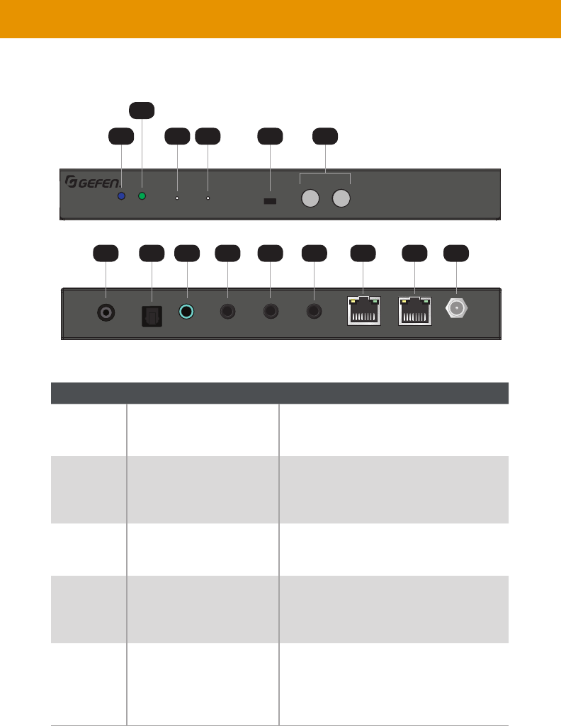
Sender Unit
2
1
6 87 9 10 11 12 13
3 4 5
Introduction
ID Name Description
1Power
unit is powered.
2
Receiver.
3 Reset Press this button, using the end of a paper clip
4Prog This button is used for device recovery
operations, in the event of a firmware update
or other failure.
5 For normal operation, this switch should be in
the On
position, places the unit in the ready-state for

12
ID Name Description
6 5V DC This power receptacle is used to connect the
included 5V DC power supply. An external
power supply is not required when connecting
port.
7 Connect a CAT-5e or better cable up to 330
feet/100 meters, from this port to a PoE-
capable network switch. If a PoE switch is
connected directly, then the included 5V DC
unit.
8 Using the included 3.5mm-to-Female-DB-9
adapator, connect an DB-9 cable from this port
232 Control (page 40 for more information.
9 IR In/Ext Connect an IR Extender (Gefen part no.
connect a 3.5mm mini-stereo connector
from this port to the electrical IR output of
an automation control system.
10 IR Out Connect an IR Emitter (Gefen part no. EXT-
IREMIT
device to be controlled.
11 Connect a 3.5mm mini-stereo cable from this
port to the analog audio source.
12
connectors from this port to the digital audio
output of a source.
13 Connect a digital audio cable with RCA
connectors from this port to the digital audio
output of a source.
Introduction
not connected, the two digital ports have the same priority. First one connected will be active. If both digital
ports are connected and then the unit is powered on, Opt In will be active. To avoid inconsistent and/or
confusing user experience, we recommend that only one type of input is connected at a time.
13
Digital and Analog Audio over IP - Receiver
5V DCLAN 2 (PoE)LAN 1IR OutIR In/ExtRS-232Line OutOpt OutCoax Out
EXT-ADA-LAN-RX
Power Link Reset Prog Prog Sel
–
CH
+
On Off
EXT-ADA-LAN-RX
Digital and Analog Audio over IP - Receiver
5V DCLAN 2 (PoE)LAN 1IR OutIR In/ExtRS-232Line OutOpt OutCoax Out
EXT-ADA-LAN-RX
Power Link Reset Prog Prog Sel
–
CH
+
On Off
EXT-ADA-LAN-RX
Receiver Unit
ID Name Description
1Power
unit is powered.
2
Receiver.
3 Reset Press this button, using the end of a paper clip
4Prog This button is used for device recovery
operations, in the event of a firmware update
or other failure.
5 For normal operation, this switch should be in
the On
position, places the unit in the ready-state for
Introduction
2
1
710 118 12
9 13 14 15
3 4 65

14
ID Name Description
6CH -/+ Press the - / + buttons button to decrement /
increment, respectively, the current channel
number.
25 for more information.
7 Connect a digital audio cable with RCA
connectors from this port to the digital audio
8
connectors from this port to the digital audio
9 Connect a 3.5mm mini-stereo cable from this
device.
10 Using the included 3.5mm-to-Male-DB-9
adapator, connect a DB-9 cable from the
Receiver to the display or another device
to be controlled
40 for more information.
11 IR In/Ext Connect an IR Extender (Gefen part no.
connect a 3.5mm mini-stereo connector
from this port to the electrical IR output of
an automation control system.
12 IR Out Connect an IR Emitter (Gefen part no. EXT-
IREMIT
device to be controlled.
13 Use this port to connect IP-enabled devices,
or to daisy-chain additional Receiver units
(only when a single source is used, otherwise
better cables up to 330 feet/100 meters. This
port is NOT PoE -capable.
Introduction
format is Bitstream, the analog output will not work.

15
Introduction
ID Name Description
14 Connect a CAT-5e or better cable up to 330
feet/100 meters, from this port to a PoE-
capable network switch. If a PoE switch is
connected directly, then the included 5V
DC power supply must be connected to the
Receiver unit.
15 5V DC This power receptacle can be used to connect
the included 5V DC power supply. An external
power supply is not required when connecting
port.
16
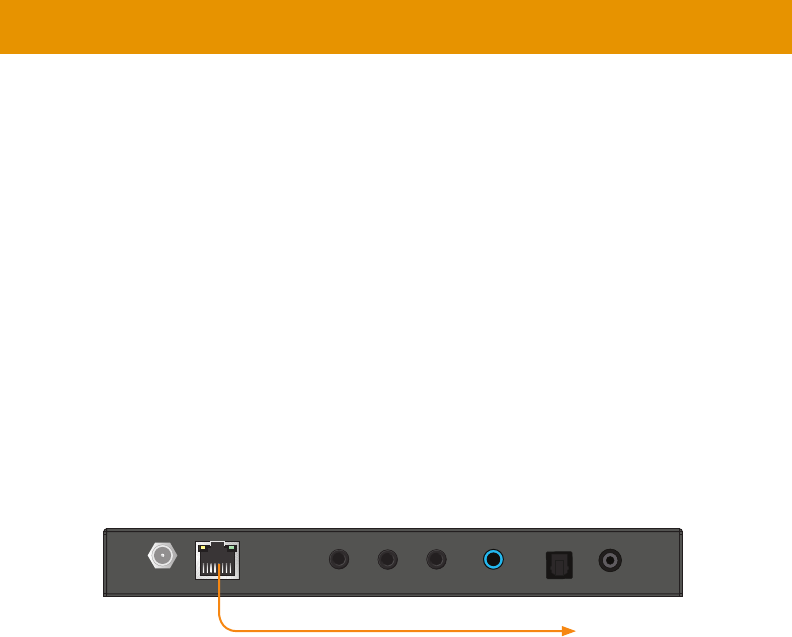
Local Area Network (LAN) Connection
DHCP mode will use the
is connected to the network. Static
APIAP mode assigns a class-B IP address, in the 169.254.x.x
Receiver units, if a DHCP server is not available.
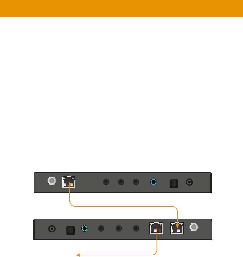
1. LAN (PoE)
Gigabit PoE-enabled IP switch.
2. Connect LAN 2 (PoE) on the Receiver unit to the same network switch. Each cable run can
3. If NOT USING A PoE-compliant switch, then connect the included 5V DC power supplies
Digital and Analog Audio over IP - Sender
Line InIR OutIR In/ExtRS-232
LAN (PoE)
5V DC Opt In Coax In
EXT-ADA-LAN-TX
Power Link Reset Prog Prog Sel
On Off
EXT-ADA-LAN-TX
Installation
Important
through their PoE ports, external power supplies will not be required. However,
require an external power supply.
to PoE-compatible switch
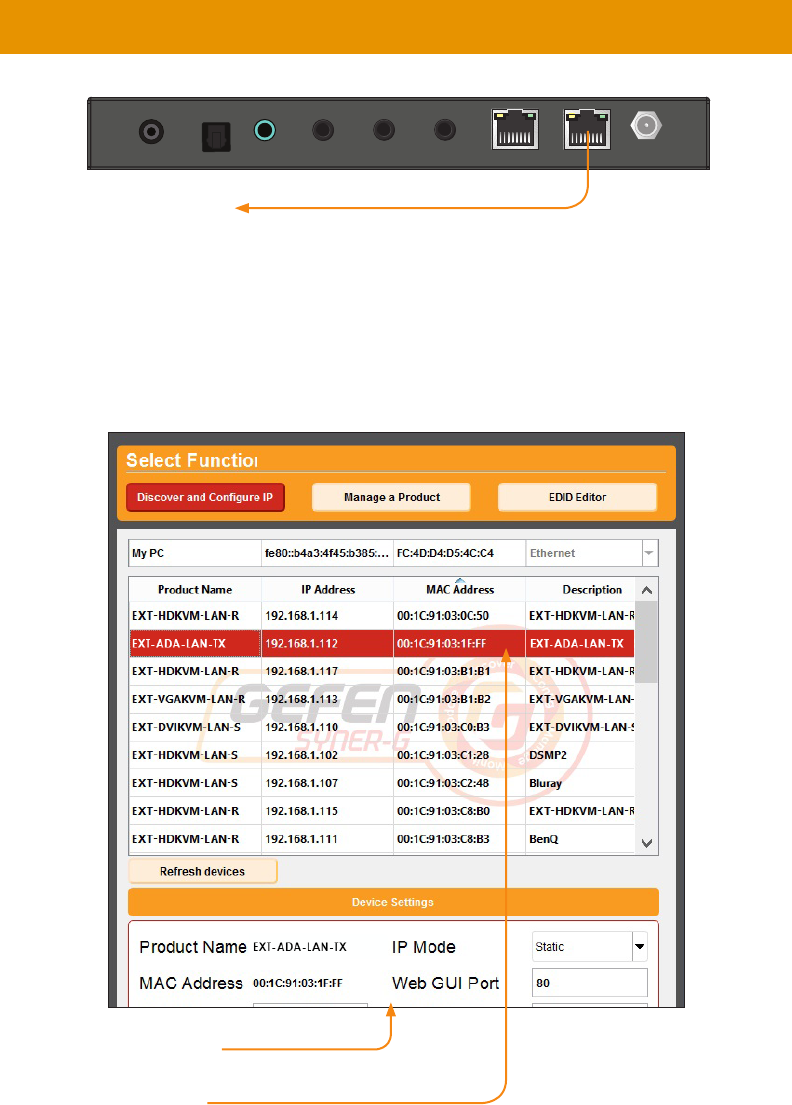
17
4. ™
™ User Manual for more information.
5. Click the desired unit from the list. The currently selected unit will be highlighted in red.
6.
Digital and Analog Audio over IP - Receiver
5V DCLAN 2 (PoE)LAN 1IR OutIR In/ExtRS-232Line OutOpt OutCoax Out
EXT-ADA-LAN-RX
Power Link Reset Prog Prog Sel
–
CH
+
On Off
EXT-ADA-LAN-RX
Installation
Receiver unit
18
7. Once all IP settings have been adjusted, click the Apply button.
8. Click the Reboot button to apply changes.
9.
10.
in the address bar.
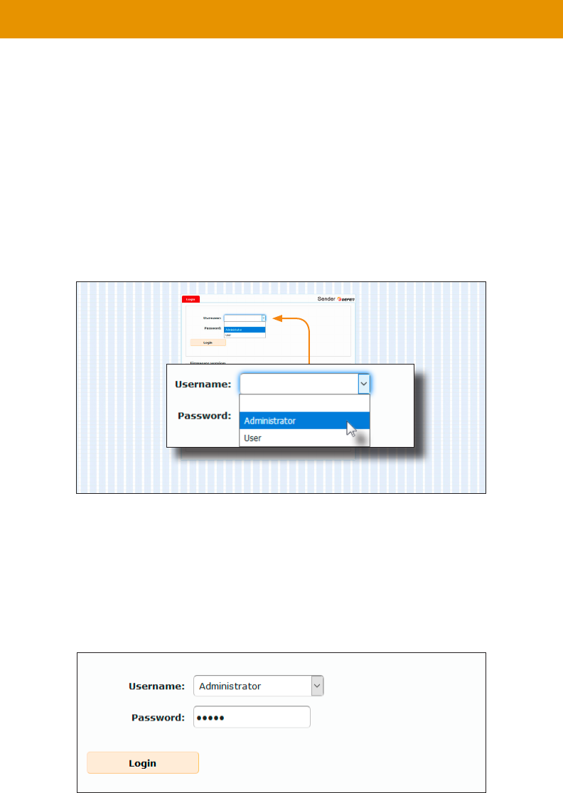
11. The Login screen will be displayed.
12.
“Administrator” username from the drop-down list.
13. Type the password in the Password
is admin. The password is case-sensitive and will be masked as it is entered.
Installation
Note
Passwords and operating features can be changed when logged in as Administrator.
The User option has limited access. To change password credentials, see Changing
for more information.
19
Installation
14. Click the Login button.
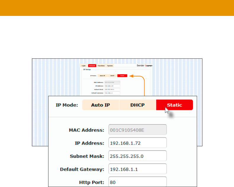
15. The Network will automatically be selected. The current IP Mode will be highlighted
16. Click the desired IP Mode button.
• If Static
Contact your system administrator if necessary.
• If DHCP mode is selected, then the IP address, subnet mask, and default gateway will be
17. Click the Apply button to save the changes. This operation will require a reboot.
18. Click the Reboot button near the bottom of the page.
19.
25 for more information.
Important
capability is required when connecting the Gefen AV over IP products to a network.
20
Digital and Analog Audio over IP - Receiver
5V DCLAN 2 (PoE)LAN 1IR OutIR In/ExtRS-232Line OutOpt OutCoax Out
EXT-ADA-LAN-RX
Power Link Reset Prog Prog Sel
–
CH
+
On Off
EXT-ADA-LAN-RX
Digital and Analog Audio over IP - Sender
Line InIR OutIR In/ExtRS-232
LAN (PoE)
5V DC Opt In Coax In
EXT-ADA-LAN-TX
Power Link Reset Prog Prog Sel
On Off
EXT-ADA-LAN-TX
Using a Direct Connection
a class-B IP address, in the 169.254.x.x
DHCP server is not available. When using a direct connection, each unit can remain in Auto
manually through the built-in web interface.
1. Connect an HDMI cable to connect the source to the HDMI In
2. Connect an HDMI cable from the display to the HDMI Out port on the Receiver unit.
3.
all connected Receivers will need to be powered using their external power supplies.
4. C
unit. Do not overtighten the locking connectors. Plug the power supplies to available
electrical outlets.
5. 16 and follow steps 4 - 19,
in order to access the built-in Web interface.
6. Make note of both IP addresses. These IP addresses can be entered in a Web browser to
access the built-in Web interface.
Installation
Receiver unit
to IP-enabled devices

21
7.
25 for more information.
8.
interface, the shielded CAT-5e cable, between the PC and the Receiver unit,
can be disconnected.
9. 22
and audio cables.
Installation

22
Installation
Supplementary Connections
►IR
1. IR Out
and attach it to the IR sensor on the device to be controlled.
2. IR In/Ext port on the
3. IR Out port on the Receiver unit
and attach it to the IR sensor on the device to be controlled.
4. IR In/Ext port on the
Receiver unit to control the audio source.
►Audio
Audio Connections (page 43 for more information on connections and port
priorities.
5. Connect a 3.5mm mini-stereo cable from the
analog audio source.
6. Connect a optical audio cable from the
connector on the audio source.
7. Connect a digital audio coaxial cable from the
digital audio source.
8. Connect a 3.5mm mini-stereo cable from the port on the Receiver unit to
9. Connect a optical audio cable from the port on the Receiver unit to the
10. Connect a digital audio coaxial cable from the port on the Receiver unit to
►RS-232
12. RS-232 port on the
13.
In is not connected, the two digital ports have the same priority. First one connected will be active. If both
digital ports are connected and then the unit is powered on, Opt In will be active. To avoid inconsistent and/
or confusing user experience, we recommend that only one type of input is connected at a time.
analog output will not work.
23
Installation
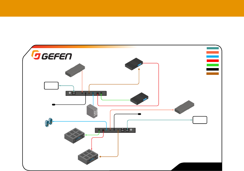
Sample Wiring Diagram
Note
and various interconnect cables that are not included with the products. The
5V DCLAN 2 (PoE)LAN 1IR OutIR In/ExtRS-232Line OutOpt OutCoax Out
EXT-ADA-LAN-RX
Line InIR OutIR In/ExtRS-232
LAN (PoE)
5V DC Opt In Coax In
EXT-ADA-LAN-TX
EXT-ADA-LAN
RS-232 CABLE
CAT-5e CABLE
3.5MM AUDIO CABLE
Analog
Audio Source
RS-232
Controlled Device
IR Emitter
EXT-ADA-LAN
Sender
EXT-ADA-LAN
Receiver
Automation
Control Device
Powered Speakers
or Audio Amplifier
w/analog L/R input
OPTICAL DIGITAL AUDIO
COAXIAL DIGITAL AUDIO
Audio Amplifier
w/ optical digital input
Audio Amplifier
w/ S/PDIF digital input
To
PoE
IP Switch
To
PoE
IP Switch
Blu-ray
Player
Blu-ray
Player
IR Extender
for remote amplifier control
IR IN
IR OUT
IR Emitter
IR Extender
for source control
OR OR
All three audio outputs of the Receiver can be used simultaneously, but if the signal format is Bitstream, the analog output will not work.
24
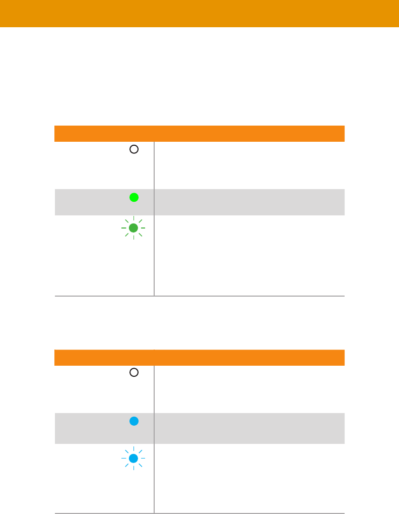
LED Status
The Power and Link
on their current status.
Link
Description
• Connection is not established.
•
unit.
On • Connection is established and audio is streaming.
Blinking
•
established but streaming has not started.
• No audio source detected.
• Check that the Receiver unit is connected to the
host.
Power
Description
• No power.
On • Power is on and the system is ready.
Blinking
•
25
set to the same channel. This is similar to changing the channel on a set-top box in order to
CH + or CH - buttons on the front
of the Receiver unit can also be used to change the channel. Both methods will be covered in
this section.
1.
unit.
2.
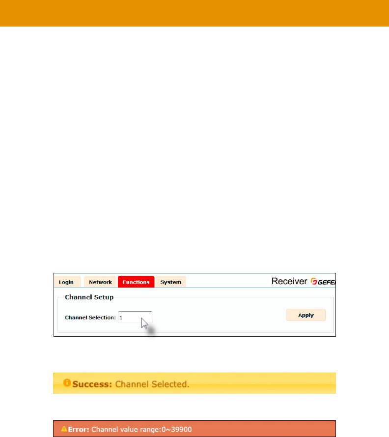
3. Click the Functions tab. The current channel is displayed within the Channel Setup
window group.
4. Type the desired channel number. Channel numbers can range from 0 to 39900.
5. Click the Apply button on the right-hand side of Channel Setup window group.
6. The following message will be displayed, at the top of the page, indicating that the
selected channel has been applied.
If the entered value is invalid, then the following message will be displayed:
7.
IP address.
8.
Setting the Audio Channel
26
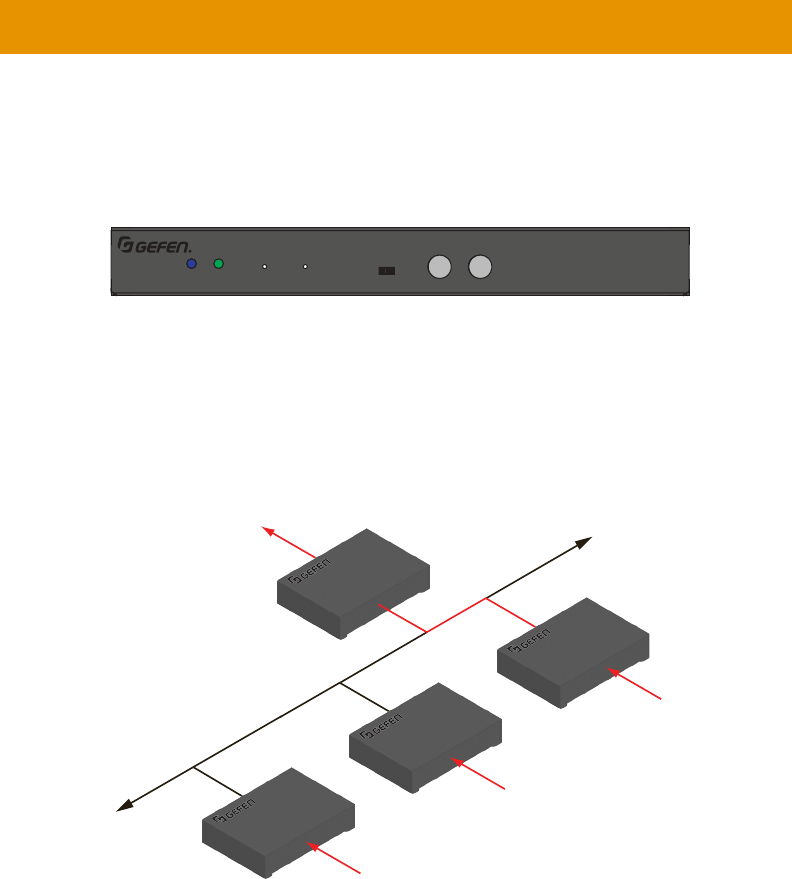
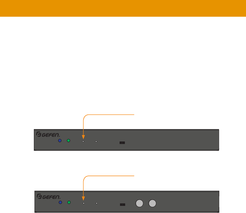
Setting the Channel using the Front Panel
1. Press the CH - or CH + change the current channel number. Channel numbers range from
0 to 39900 and can be viewed in the Web interface.
-
for more information.
The illustration below shows one Receiver -
dicate the audio channel for each unit. Here, the Receiver unit is currently set to channel
5, press and release the CH + button to increment the channel. The web interface will
Setting the Audio Channel
Receiver unit
Digital and Analog Audio over IP - Receiver
5V DCLAN 2 (PoE)LAN 1IR OutIR In/ExtRS-232Line OutOpt OutCoax Out
EXT-ADA-LAN-RX
Power Link Reset Prog Prog Sel
–
CH
+
On Off
EXT-ADA-LAN-RX
LAN
Receiver unit
Out
Sender unit
Sender unit
Sender unit
In
In
In
2
5
1
2
27
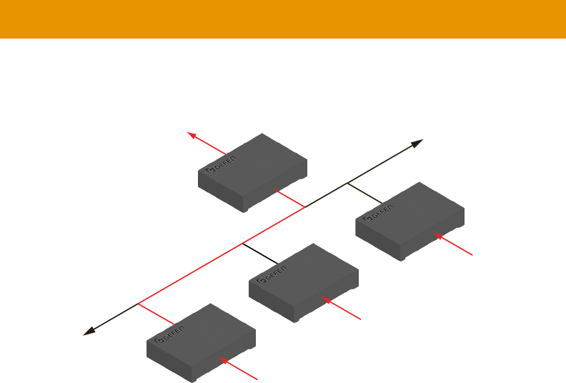
Setting the Audio Channel
2. The Receiver unit, on channel 5, is now receiving the signal from the Sender unit on
channel 5.
LAN
Receiver unit
Out
Sender unit
Sender unit
Sender unit
In
In
In
5
5
1
2
28
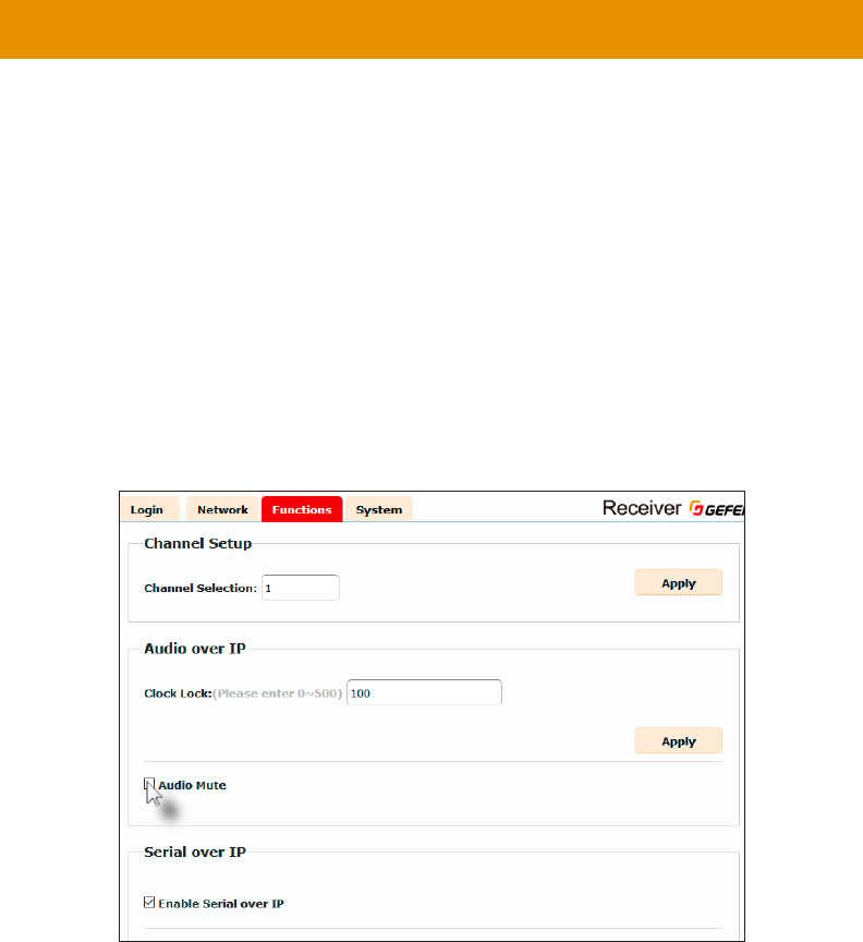
Muting Audio
Use the Mute Audio
of the connected Receiver units (multicast modeMute Audio option on the
Receiver units, to selectively block audio on each Receiver unit.
►Receiver Units
1. Access the Web interface of a Receiver unit by entering the IP address in the address bar
of the browser.
2.
3. Click the Functions tab.
4. Under the Audio over IP window group, check the Audio Mute box to block the audio
output on the Receiver unit. Deselect this check box to re-enable audio.
5. Click the Apply button within the Audio over IP group.
6. Repeat steps 1 through 5 for each Receiver unit in the system.
29
Muting Audio
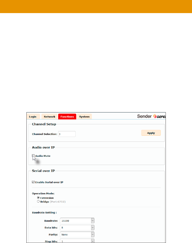
►
1.
the browser.
2.
3. Click the Functions tab.
4. Under the Audio over IP window group, check the Audio Mute box to prevent audio from
being transmitted to each of the connected Receiver units. Deselect this check box to
re-enable audio output on all connected Receiver units..
5. Click the Apply button within the Audio over IP group.
6.
Note
The Mute Audiomulticast mode.
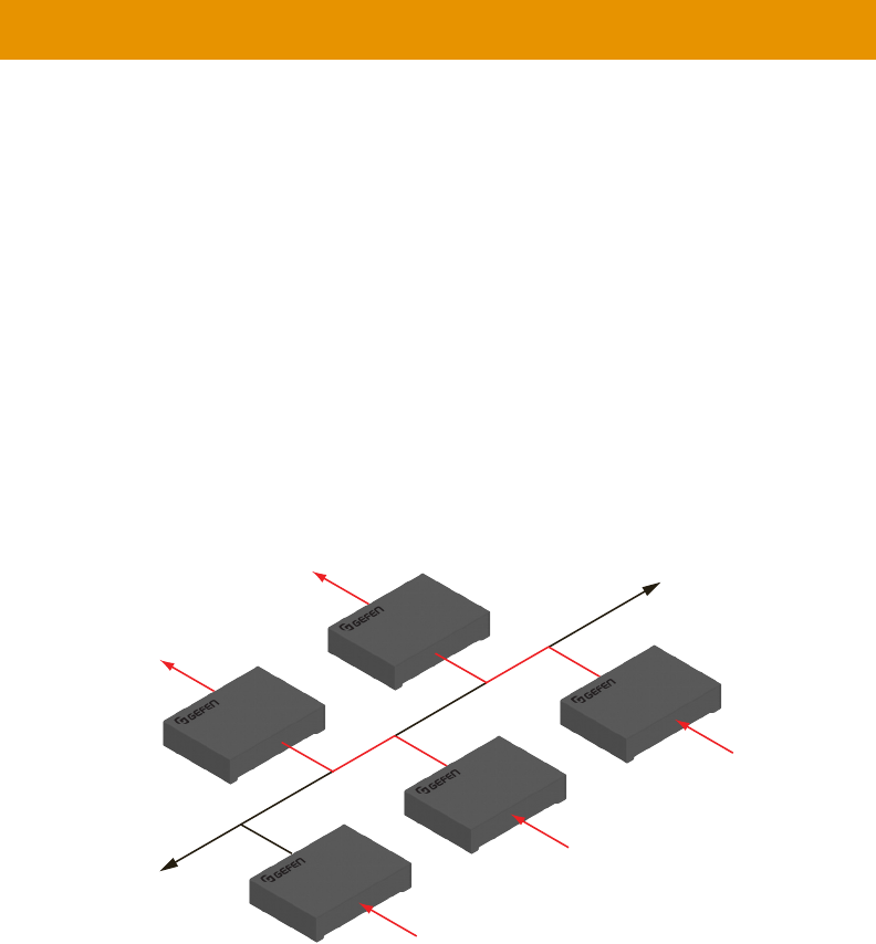
30
Unicast & Multicast Modes
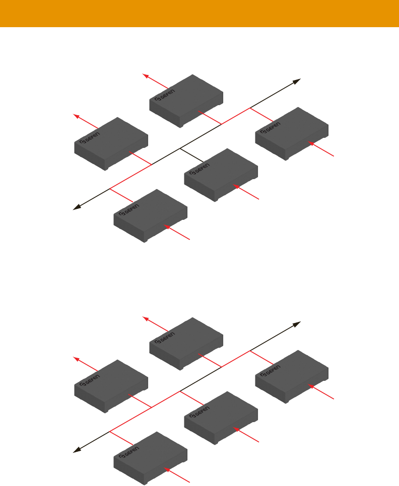
The term unicast
system. However, in unicast
at a time. In unicast mode, the Gefen AV over IP products function similar to an audio switcher.
unicast mode. The audio channels are notated
in blue.
Figure 2.1 - Unicast mode: A Sender unit can communicate with only one Receiver unit at a time.
1. unicast
mode. In this example, we will start with Receiver unit R1.
2.
LAN
Receiver unit
Receiver unit
Out
Out
Sender unit
Sender unit
Sender unit
In
In
In
R
1
R
2
S
2
S
3
S
1
2
1
5
1
2
Note
unicast mode.
Tip
switcher.
31
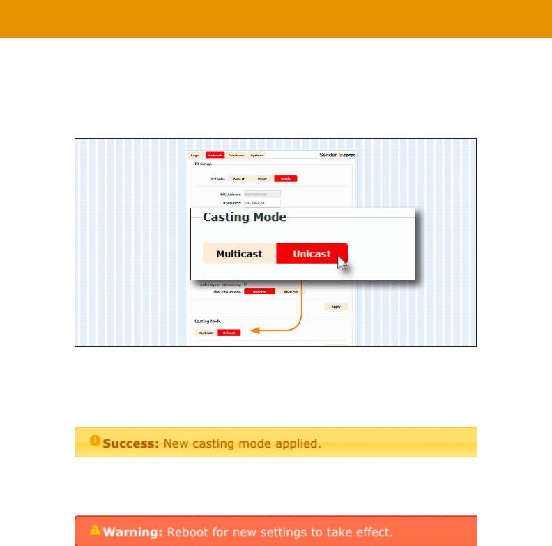
Unicast & Multicast Modes
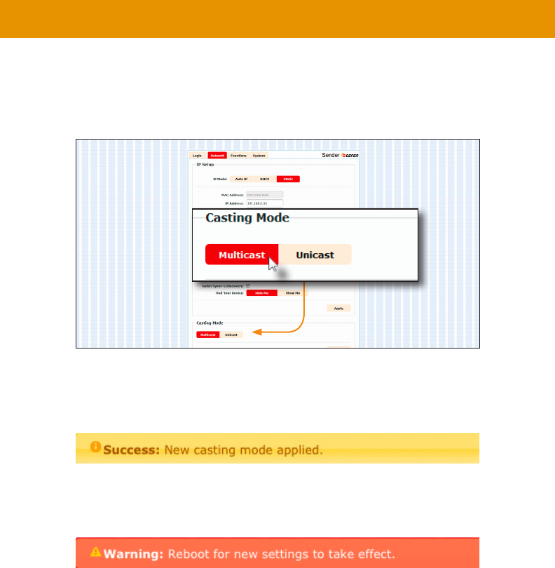
3. Click the Network tab.
4. Click the Unicast button under the Network Mode window group. When selected,
the Unicast button will be highlighted in red.
5. Click the Apply button in the lower-right corner of the Network Mode group.
6. The following message will be displayed, at the top of the page, indicating that the
7. Click the Reboot button at the bottom of the page. If the Reboot button is not clicked,
the following message will be displayed, indicating that the unit must be rebooted.
8. unicast mode.
Important
When switching between unicast and multicast
units must be set to the same mode.
32
Unicast & Multicast Modes
Switching between Sender units in Unicast mode
unicast mode, the Gefen Audio over IP
unicast mode, a
with only one Receiver unit at a time.
In the example below, Receiver unit R1 will be switched to receive the source connected to
Figure 2.2 - Unicast mode: Receiver unit R1 is connected to Sender unit S2.
1. Access the Web interface for Receiver unit R1.
2. Login as “Administrator”.
3. Click the Network tab and change the audio channel. Refer to
Channel (page 25 if necessary.
4. Click the Apply button.
5. The following message will be displayed, at the top of the page, indicating that the
new channel has been applied to the Sender or Receiver unit.
6. Receiver unit R1 is now receiving the audio source connected to Sender unit S1, as
shown on the next page.
LAN
Receiver unit
Receiver unit
Out
Out
Sender unit
Sender unit
Sender unit
In
In
In
R
1
R
2
S
2
S
3
S
1
2
1
5
1
2
33
Unicast & Multicast Modes
Figure 2.3 - Unicast mode: Receiver unit R1 is now connected to Sender unit S1.
Figure 2.4 - Unicast mode violation: Two Sender units (S1 and S2) using the same audio channel.
unicast mode rule: A
at a time.
LAN
Receiver unit
Receiver unit
Out
Out
Sender unit
Sender unit
Sender unit
In
In
In
R
1
R
2
S
2
S
3
S
1
2
5
5
1
2
LAN
Receiver unit
Receiver unit
Out
Out
Sender unit
Sender unit
Sender unit
In
In
In
R
1
R
2
S
2
S
3
S
1
2
5
5
5
2

34
Unicast & Multicast Modes
Note
In unicast
35
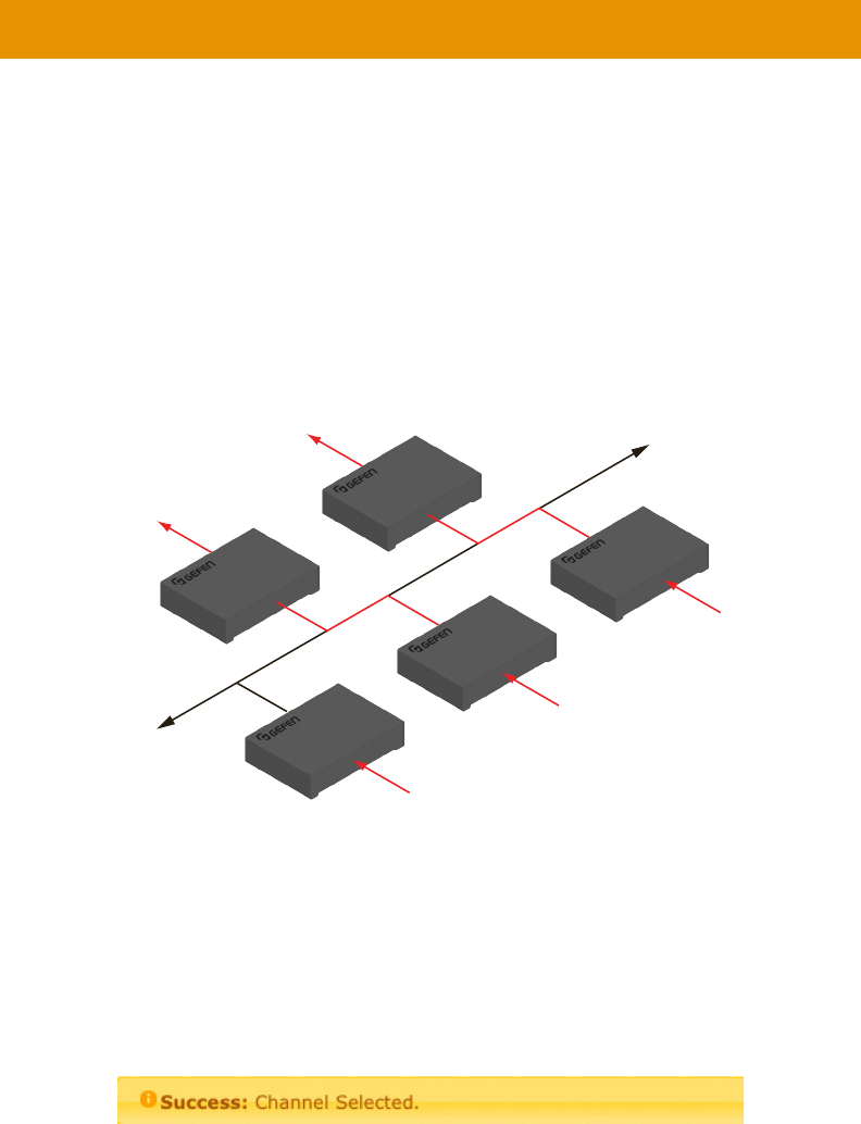
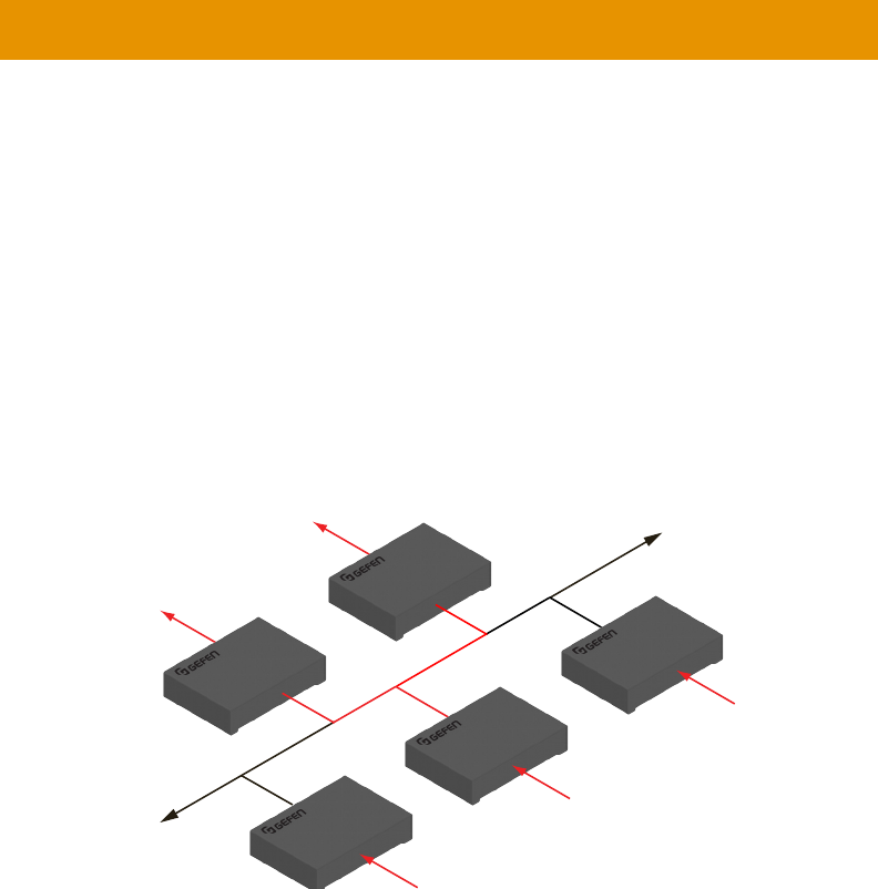
In multicast
multicast mode. The audio channels are shown
in blue.
Figure 2.5 - Multicast mode: A Sender unit can communicate with multiple Receiver units.
1. multicast
mode
2.
Unicast & Multicast Modes
LAN
Receiver unit
Receiver unit
Out
Out
Sender unit
Sender unit
Sender unit
In
In
In
R
1
R
2
S
2
S
3
S
1
1
1
5
1
2
Note
In multicast mode
matrix.
36
3. Click the Network tab.
4. Click the Multicast button under the Network Mode window group. When selected,
the Multicast button will be highlighted in red.
5. Click the Apply button in the lower-right corner of the Network Mode group.
The following message will be displayed, at the top of the page, indicating that the
6. Click the Reboot button at the bottom of the page. If the Reboot button is not clicked,
the following message will be displayed, indicating that the unit must be rebooted.
7. multicast mode.
Unicast & Multicast Modes
Important
When switching between unicast and multicast
units must be set to the same mode.
37
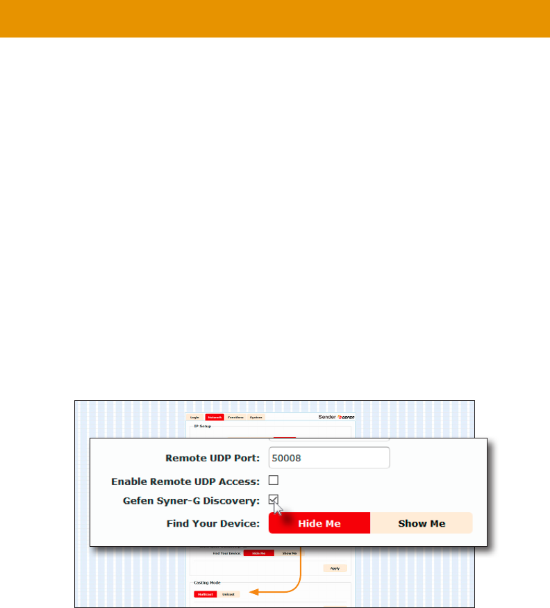
Discovery Mode
is able to locate the unit, IP settings can be changed as desired.
1.
2.
3. Click the Network tab.
4. Under the IP Setup window group, check the box to
discoverable, then un-check this box.
5. Click the Apply button.
6. Click the Reboot button at the bottom of the page to restart the unit and apply
the change.
38
Discovery Mode
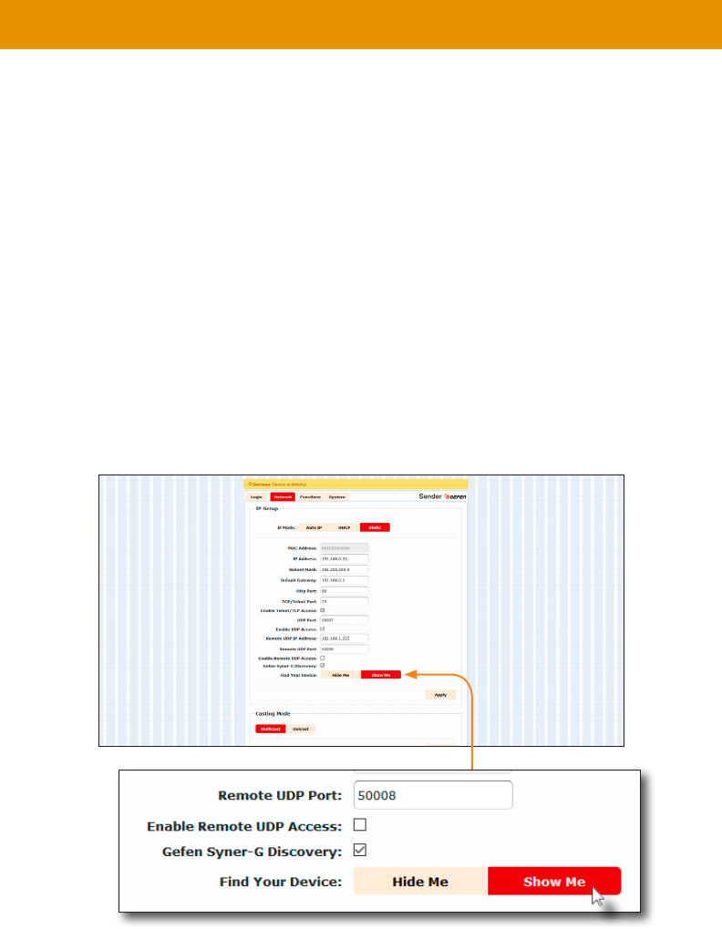
Finding Your Device
Find Your
Device feature.
1.
2.
3. Click the Network tab.
4. Under the IP Setup window group, click the Show Me button. By default, the Hide Me
button will be selected.
Although shown, below, it is not necessary to have the
option enabled in order to use the Find Your Device feature.
39
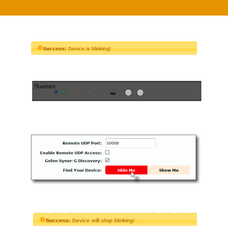
5. The following message will be displayed, at the top of the page, indicating that the
LED indicators on the unit are blinking.
6. The Power and Link LED indicators will continue to blink until the Hide Me button is
clicked.
7. Click the Hide Me button to stop both LED indicators from blinking.
8. The Power and Link LED indicators will stop blinking and the following message will
be displayed at the top of the page.
Digital and Analog Audio over IP - Receiver
5V DCLAN 2 (PoE)LAN 1IR OutIR In/ExtRS-232Line OutOpt OutCoax Out
EXT-ADA-LAN-RX
Power Link Reset Prog Prog Sel
–
CH
+
On Off
EXT-ADA-LAN-RX
Discovery Mode
40
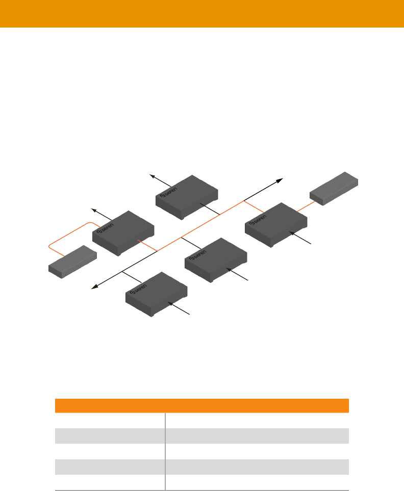
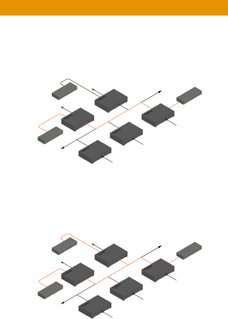
RS-232 Control
are listed in blue.
Figure 2.6 - Basic RS-232 connection
Table 2.1 - RS-232 settings for an arbitrary RS-232 device.
Description Setting
Baud rate 19200
Data bits 8
Parity None
1
None
LAN
Receiver unit
Receiver unit
Out
Out
Sender unit
Sender unit
Sender unit
In
In
In
RS-232 device
Automation
Control Device
12
12
02
05
09
R
1
S
1
S
2
S
3
R
2
41
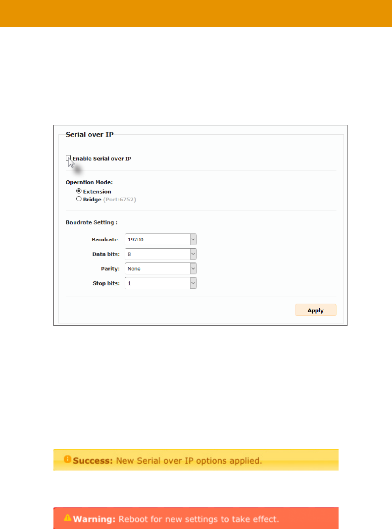
RS-232 Control
1.
2. Click the Functions tab.
3. Serial over IP
4. Make sure that the Enable Serial over IP box is checked.
5. Click the Apply button in the lower-right corner of the Serial over IP group.
6. The following message will be displayed, at the top of the page, indicating that the new
7. Click the Reboot button at the bottom of the page. If the Reboot button is not clicked,
the following message will be displayed, indicating that the unit must be rebooted.
8. Repeat steps 1 - 7 for the Receiver unit.
Important
If Enable Serial over IP
42
RS-232 Control
RS-232 under Unicast Mode
In unicast mode
at a time.
Figure 2.7 - In unicast mode, the host can talk to only one RS-232 device at a time.
RS-232 under Multicast Mode
simultaneously.
Figure 2.8 - In multicast mode, the host can talk to multiple RS-232 devices.
LAN
Receiver unit
Receiver unit
Out
Out
Sender unit
Sender unit
Sender unit
In
In
In
Automation
Control Device
RS-232 device
RS-232 device
12
12
02
05
09
R
1
S
1
S
2
S
3
R
2
LAN
Receiver unit
Receiver unit
Out
Out
Sender unit
Sender unit
Sender unit
In
In
In
Automation
Control Device
RS-232 device
RS-232 device
12
12
12
05
09
R
1
S
1
S
2
S
3
R
2
43
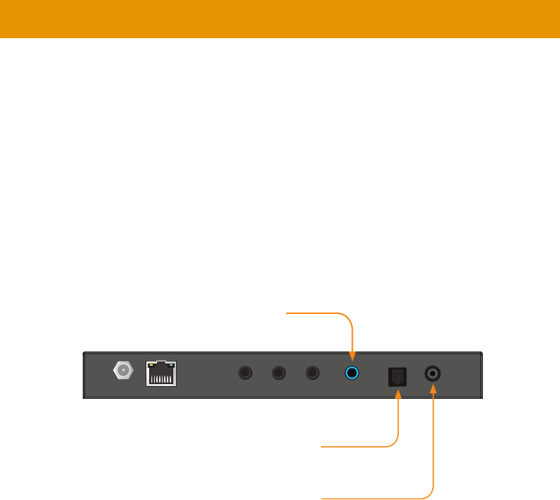
Audio Connections
priorities, based on the type and the order in which they are connected.
Sender Unit
1. Connect a 3.5mm mini-stereo cable from the
analog audio source.
2. Connect a optical audio cable from the
connector on the audio source.
3. Connect a digital audio coaxial cable from the
digital audio source.
Audio Port Priority section.
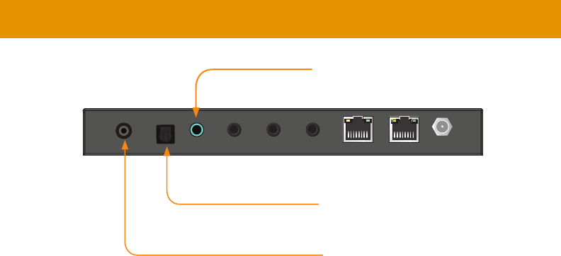
Receiver Unit
1. Connect a 3.5mm mini-stereo cable from the port on the Receiver unit to
2.
3. Connect a coaxial digital audio cable from the port on the Receiver unit to
the digital input port of an audio amplifer.
Digital and Analog Audio over IP - Sender
Line InIR OutIR In/ExtRS-232
LAN (PoE)
5V DC Opt In Coax In
EXT-ADA-LAN-TX
Power Link Reset Prog Prog Sel
On Off
EXT-ADA-LAN-TX
Connect to Line Out on analog source
Connect to optical audio output
on source
Connect to digital audio output
on source
44
Digital and Analog Audio over IP - Receiver
5V DCLAN 2 (PoE)LAN 1IR OutIR In/ExtRS-232Line OutOpt OutCoax Out
EXT-ADA-LAN-RX
Power Link Reset Prog Prog Sel
–
CH
+
On Off
EXT-ADA-LAN-RX
Audio Connections
Audio Port Priority
When the Line In
(Opt In and Coax InLine In is not connected, then the two digital ports have the same
Opt In port
always has priority and will become the active audio input port.
All three audio ports (Line Out, Opt Out, and Coax Out
Connect to powered speakers or
Receiver unit
Connect to optical audio input
Connect to digital audio input
Audio Port Priority section.
45
Audio Connections
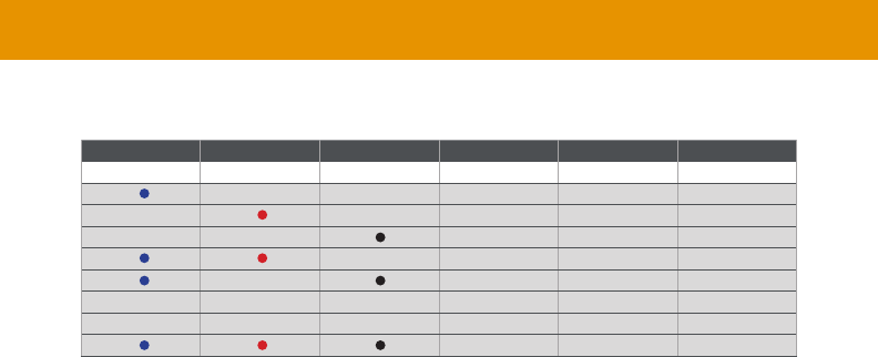
Transmitter Receiver
Line In Opt In Coax In Line Out Opt Out Coax Out
Opt In Opt In Opt In
Coax In Coax In Coax In
First Opt In Opt In Opt In
First Coax In Coax In Coax In
Audio Port Priority Summary
46
1.
2.
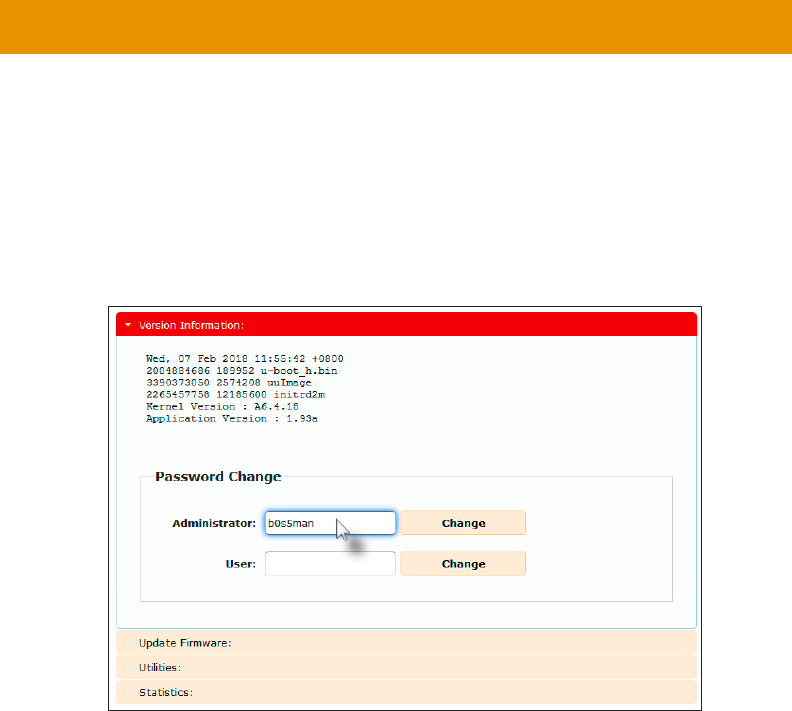
3. Click the System tab.
4. Under the Password Change window group, enter the new password for the desired
username. Note that the new password will not be masked when it is entered.
5. Click the Change button.
Changing the Password
47
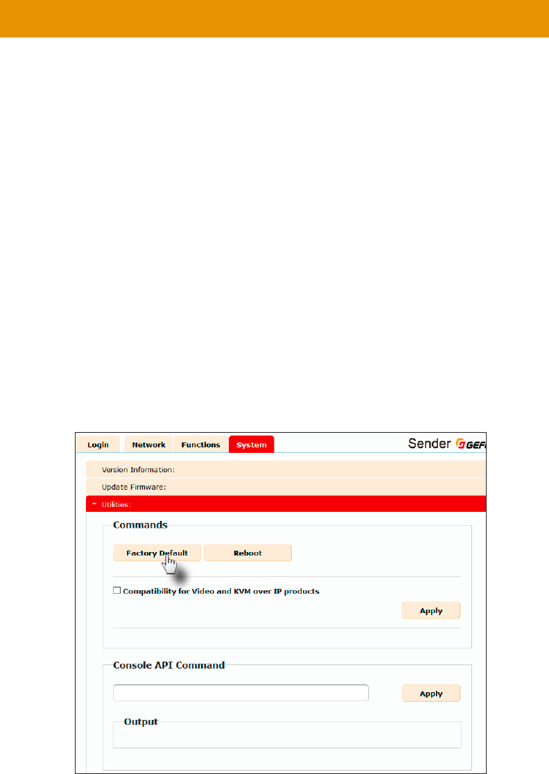
Utilities
can be reset using the web interface or using the buttons on the
reset to Auto IP
to either Auto IP or Static IP mode.
1. It does not matter which
2.
3. Click the System tab.
4. Click the Utilities rollout.
5. Click the button.
Note
Once a unit has been reset to Auto IP mode, the connection to the Web interface
will be terminated. To reestablish a connection to the Web interface, from your
computer, see .

48
5. Both the Power and Link
6.
7. Repeat the process for each unit.
Digital and Analog Audio over IP - Receiver
5V DCLAN 2 (PoE)LAN 1IR OutIR In/ExtRS-232Line OutOpt OutCoax Out
EXT-ADA-LAN-RX
Power Link Reset Prog Prog Sel
–
CH
+
On Off
EXT-ADA-LAN-RX
Utilities
49
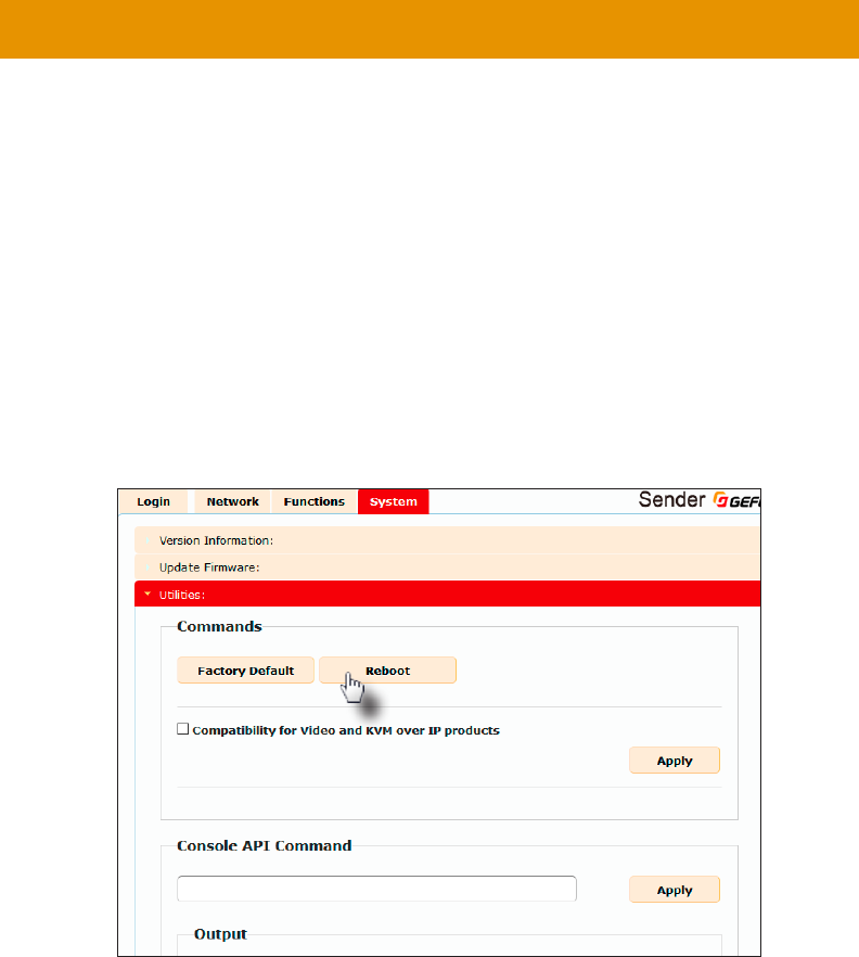
Utilities
Reboot
interface, the Reset button on the front panel, or simply disconnecting and reconnecting the
power.
1.
2.
3. Click the System tab.
4. Click the Utilities rollout.
5. Click the Reboot button.
6. Power
7. PowerLink
8.
50
Digital and Analog Audio over IP - Sender
Line InIR OutIR In/ExtRS-232
LAN (PoE)
5V DC Opt In Coax In
EXT-ADA-LAN-TX
Power Link Reset Prog Prog Sel
On Off
EXT-ADA-LAN-TX
Digital and Analog Audio over IP - Receiver
5V DCLAN 2 (PoE)LAN 1IR OutIR In/ExtRS-232Line OutOpt OutCoax Out
EXT-ADA-LAN-RX
Power Link Reset Prog Prog Sel
–
CH
+
On Off
EXT-ADA-LAN-RX
Reboot using the Front Panel
1. Press the Reset
of a paper clip or other sharp pointed object.
2. Power
3. PowerLink
4.
Utilities
Reset button
Receiver unit
Reset button

51
Telnet Access
1.
2.
wish to control.
3. Enter the TCP listening port. The default listening port is 23.
4.
the following will be displayed.
been enabled:
------------- Welcome to the Gefen Telnet Server -------
----
ast2-client001C9103C8B3 login:
5. -
word, see the #set_telnet_pass command.
6. Type #help for a list of commands or refer to the tables on the following pages.
Note
By default, the Telnet login credentials are disabled. This setting is required when
security purposes. Use the #use_telnet_login command to enable or
disable this feature.

52
Commands
Important
and “Rx only”, respectively. Unless otherwise noted, commands can be used when
Command Description
#get_device_desc Displays the device description
#get_discovery Displays the current state of the discovery service
#get_discovery_mode Displays the discovery read/write mode
#get_showme Displays the status of the showme state
#set_device_desc
#set_discovery Enables or disables the discovery service
#set_discovery_mode
#set_showme Enables or disables the “show me” feature
Command Description
#help Displays a list of available commands
Command Description
#get_gateway Displays the gateway IP address
#get_ip_address Displays the IP address
#get_ip_mode Displays the IP mode
#get_ipcong
#get_net_mode Displays the network casting mode
#get_netmask Displays the subnet mask address
#get_remote_udp_access Displays the remote UDP access state
#get_remote_udp_ip Displays the remote UDP IP address
#get_remote_udp_port Displays the remote UDP listening port
#get_telnet_access Displays the Telnet access state
Network
Discovery Service
Help

53
Command Description
#get_telnet_login Displays the status of the Telnet login
#get_telnet_port Displays the Telnet listening port
#get_telnet_welcome Displays the Telnet welcome message
#get_udp_access Displays the UDP access state
#get_udp_port Displays the UDP listening port
#get_web_port Displays the HTTP listening port
#set_gateway
#set_ip_address
#set_ip_mode
#set_net_mode
#set_netmask
#set_remote_udp_access Enables or disables remote UDP access
#set_remote_udp_ip
#set_remote_udp_port
#set_telnet_access Enables or disables Telnet access
#set_telnet_login Enables or disables the Telnet login
#set_telnet_pass
#set_telnet_port
#set_telnet_welcome
#set_udp_access Enables or disables UDP access
#set_udp_port
#set_web_port
Command Description
#get_rx_channel
r
Routing
Commands

54
Command Description
#get_clk_lock Displays the audio clock lock
#get_rx_id Displays the ID of the Receiver unit
#get_rx_mute Displays the audio mute feature state
#set_clk_lock
#set_rx_id
#set_rx_mute
Commands

55
Commands
Command Description
#get_rmware_version
#factory_reset Resets the unit to factory-default settings
#fw_upgrade
#reboot Reboots the unit
Command Description
#get_tx_channel Displays the audio channel
#set_tx_channel
System
Command Description
#get_serial_allow
#get_serial_baud Displays the serial baud rate setting
#get_serial_bits Displays the serial data bits setting
#get_serial_parity Displays the serial parity setting
#get_serial_stop Displays the serial stop bits setting
#set_serial_allow
#set_serial_baud
#set_serial_bits
#set_serial_parity
#set_serial_stop
Serial
Command Description
#set_webui_ad_pass
#set_webui_user_pass

56
Commands
#help
or Receiver unit.
Syntax
#help
Parameters
None
Example
#help
#HELP
#FACTORY_RESET
#FW_UPGRADE
#GET_CLK_LOCK
#GET_DEVICE_DESC
#GET_DISCOVERY
#GET_DISCOVERY_MODE
#GET_EDID_COPY
#GET_FIRMWARE_VERSION
#GET_GATEWAY
#GET_HDCP
#GET_IP_ADDRESS
#GET_IP_MODE
#GET_IPCONFIG
#GET_NET_MODE
#GET_NETMASK
#GET_REMOTE_UDP_ACCESS
#GET_REMOTE_UDP_IP
#GET_REMOTE_UDP_PORT
#GET_RX_CHANNEL
...
...

57
Commands
#factory_reset
Resets the unit to factory-default settings. param1 must be included and set to 1.
Syntax
#factory_reset param1
Parameters
param1 Integer 1
Example
#factory_reset 1
RESET TO FACTORY DEFAULTS
Related Commands
#reboot

58
Commands
#fw_upgrade
Syntax
#fw_upgrade lename
Parameters
lename
Example
#fw_upgrade rmware_le_v2.bin

59
Commands
#get_clk_lock
Displays the audio clock lock.
Syntax
#get_clk_lock
Parameters
None
Example
#get_clk_lock
CLK_LOCK 0
Related Commands
#set_clk_lock

60
Commands
#get_device_desc
Syntax
#get_device_desc
Parameters
None
Example
#get_device_desc
DEVICE DESCRIPTION IS Genius Sender 2
Related Commands
#set_device_desc

61
Commands
#get_discovery
Displays the current discovery mode setting.
Syntax
#get_discovery
Parameters
None
Example
#get_discovery
DISCOVERY SERVICE SET TO ENABLED
Related Commands
#set_discovery
#set_showme

62
Commands
#get_discovery_mode
Displays the current discovery mode setting.
Syntax
#get_discovery_mode
Parameters
None
Example
#get_discovery_mode
DISCOVERY MODE 1
Related Commands
#set_discovery
#set_discovery_mode
#set_showme

63
Commands
#get_rmware_version
Syntax
#get_rmware_version
Parameters
None
Example
#get_rmware_version
FIRMWARE VERSION IS 1.83hv
Related Commands
#fw_upgrade

#get_gateway
Syntax
#get_gateway
Parameters
None
Example
#get_gateway
GATEWAY: 192.168.0.1
Related Commands
#get_ip_address
#get_ip_mode
#get_ipcong
#get_netmask
#set_gateway
#set_ip_address
#set_ip_mode
#set_netmask
Commands
64

#get_ip_address
Syntax
#get_ip_address
Parameters
None
Example
#get_ip_address
IP: 10.5.64.60
Related Commands
#get_gateway
#get_ip_mode
#get_ipcong
#get_netmask
#get_web_port
#set_gateway
#set_ip_address
#set_ip_mode
#set_netmask
#set_web_port
Commands
65

#get_ip_mode
Displays the current IP mode.
Syntax
#get_ip_mode
Parameters
None
Example
#get_ip_mode
IP MODE IS SET TO DHCP
Related Commands
#get_gateway
#get_ip_address
#get_ipcong
#get_netmask
#get_web_port
#set_gateway
#set_ip_address
#set_ip_mode
#set_netmask
#set_web_port
Commands
66

#get_ipcong
broadcast IP address, this command also provides the same information as executing the
#get_ip_mode, #get_ip_address, #get_netmask, and #get_gateway
commands.
Syntax
#get_ipcong
Parameters
None
Example
#get_ipcong
IP CONFIGURATION IS :
IP MODE: DHCP
IP: 10.5.64.60
NETMASK: 255.255.255.0
GATEWAY: 10.5.64.1
MAC ADDRESS: 00-1C-91-03-C8-B3
Related Commands
#get_gateway
#get_ip_address
#get_netmask
#get_web_port
#set_gateway
#set_ip_address
#set_ip_mode
#set_netmask
#set_web_port
Commands
67

#get_net_mode
Displays the current network mode setting.
Syntax
#get_net_mode
Parameters
None
Example
#get_net_mode
NETWORK MODE SET TO MULTICAST
Related Commands
#set_net_mode
Commands
68

#get_netmask
Displays the current net mask setting.
Syntax
#get_netmask
Parameters
None
Example
#get_netmask
NETMASK: 255.255.255.0
Related Commands
#get_gateway
#get_ip_address
#get_ipcong
#get_web_port
#set_gateway
#set_ip_address
#set_ip_mode
#set_netmask
#set_web_port
Commands
69

#get_remote_udp_access
Displays the remote UDP access state.
Syntax
#get_remote_udp_access
Parameters
None
Example
#get_remote_udp_access
REMOTE UDP ACCESS IS ENABLED
Related Commands
#get_remote_udp_ip
#get_remote_udp_port
#get_udp_access
#get_udp_port
#set_remote_udp_access
#set_remote_udp_ip
#set_remote_udp_port
#set_udp_access
#set_udp_port
Commands
70

#get_remote_udp_ip
Displays the remote UDP IP address.
Syntax
#get_remote_udp_ip
Parameters
None
Example
#get_remote_udp_access
REMOTE UDP IP: 192.168.1.29
Related Commands
#get_remote_udp_access
#get_remote_udp_port
#get_udp_access
#get_udp_port
#set_remote_udp_access
#set_remote_udp_ip
#set_remote_udp_port
#set_udp_access
#set_udp_port
Commands
71

#get_remote_udp_port
Displays the remote UDP listening port.
Syntax
#get_remote_udp_port
Parameters
None
Example
#get_remote_udp_port
REMOTE UDP COMMUNICATIONS PORT: 50008
Related Commands
#get_remote_udp_access
#get_remote_udp_ip
#get_udp_access
#get_udp_port
#set_remote_udp_access
#set_remote_udp_ip
#set_remote_udp_port
#set_udp_access
#set_udp_port
Commands
72


#get_rx_id
Displays the ID of the Receiver unit. This command is only available when connected
to a Receiver unit.
Syntax
#get_rx_id
Parameters
None
Example
#get_rx_id
RX ID: 8
Related Commands
#set_rx_id
Commands
74

#get_rx_mute
Displays the audio mute feature state. Use the #set_rx_mute command to set
enable/disable the audio mute feature. This command is only available when connected
to a Receiver unit.
Syntax
#get_rx_mute
Parameters
None
Example
#get_rx_mute
RX_MUTE 0
Related Commands
#set_rx_mute
Commands
75

#get_serial_allow
#set_serial_allow command to enable
Syntax
#get_serial_allow
Parameters
None
Example
#get_serial_allow
SERIAL OVER IP is ENABLE
Related Commands
#get_serial_baud
#get_serial_parity
#get_serial_stop
#set_serial_allow
#set_serial_baud
#set_serial_bits
#set_serial_parity
#set_serial_stop
Commands
76

#get_serial_baud
Displays the serial baud rate setting. Use the #set_serial_baud command to set
the baud rate.
Syntax
#get_serial_baud
Parameters
None
Example
#get_serial_baud
SERIAL BAUD RATE IS 19200
Related Commands
#get_serial_allow
#get_serial_bits
#get_serial_parity
#get_serial_stop
#set_serial_allow
#set_serial_baud
#set_serial_bits
#set_serial_parity
#set_serial_stop
Commands
77

#get_serial_bits
Displays the serial data bits setting. Use the #set_serial_bits command to set
the number of data bits.
Syntax
#get_serial_bits
Parameters
None
Example
#get_serial_bits
SERIAL DATA BITS IS 8
Related Commands
#get_serial_allow
#get_serial_baud
#get_serial_parity
#get_serial_stop
#set_serial_allow
#set_serial_baud
#set_serial_bits
#set_serial_parity
#set_serial_stop
Commands
78

#get_serial_parity
Displays the serial parity bit setting. Use the #set_serial_parity command to set
the parity bit.
Syntax
#get_serial_parity
Parameters
None
Example
#get_serial_parity
SERIAL PARITY MODE SET TO NONE
Related Commands
#get_serial_allow
#get_serial_baud
#get_serial_bits
#get_serial_stop
#set_serial_allow
#set_serial_baud
#set_serial_bits
#set_serial_parity
#set_serial_stop
Commands
79

#get_serial_stop
Displays the serial stop bits setting. Use the #set_serial_stop command to set
the number of stop bits.
Syntax
#get_serial_stop
Parameters
None
Example
#get_serial_stop
SERIAL STOP BITS IS 1
Related Commands
#get_serial_allow
#get_serial_baud
#get_serial_bits
#get_serial_parity
#set_serial_allow
#set_serial_baud
#set_serial_bits
#set_serial_parity
#set_serial_stop
Commands
80

#get_showme
Displays the showme state.
Syntax
#get_showme
Parameters
None
Example
#get_showme
SHOW ME DISABLED
Related Commands
#set_showme
Commands
81

#get_telnet_access
Displays the Telnet access state. Use the #set_telnet_access command to enable
or disable Telnet access.
Syntax
#get_telnet_access
Parameters
None
Example
#get_telnet_access
TELNET ACCESS IS ENABLED
Related Commands
#get_telnet_login
#get_telnet_port
#get_telnet_welcome
#set_telnet_access
#set_telnet_pass
#set_telnet_login
#set_telnet_pass
#set_telnet_port
#set_telnet_welcome
Commands
82

#get_telnet_login
Displays the Telnet login status.
Syntax
#get_telnet_login
Parameters
None
Example
#get_telnet_login
TELNET LOGIN SET TO DISABLED
Related Commands
#get_telnet_access
#get_telnet_port
#get_telnet_welcome
#set_telnet_access
#set_telnet_pass
#set_telnet_login
#set_telnet_pass
#set_telnet_port
#set_telnet_welcome
Commands
83

#get_telnet_port
Displays the Telnet listening port.
Syntax
#get_telnet_port
Parameters
None
Example
#get_telnet_port
TELNET COMMUNICATION PORT: 23
Related Commands
#get_telnet_access
#get_telnet_login
#get_telnet_welcome
#set_telnet_access
#set_telnet_pass
#set_telnet_login
#set_telnet_pass
#set_telnet_port
#set_telnet_welcome
Commands
84

#get_telnet_welcome
Displays the Telnet welcome message. Use the #set_telnet_welcome to create
a custom welcome message.
Syntax
#get_telnet_welcome
Parameters
None
Example
#get_telnet_welcome
TELNET WELCOME SCREEN IS DISABLED
Related Commands
#get_telnet_access
#get_telnet_login
#get_telnet_port
#set_telnet_access
#set_telnet_pass
#set_telnet_login
#set_telnet_pass
#set_telnet_port
#set_telnet_welcome
Commands
85

#get_tx_channel
Syntax
#get_tx_channel
Parameters
None
Example
#get_tx_channel
TRANSMITTER CHANNEL: 1
Related Commands
#get_rx_channel
#set_tx_channel
r
Commands
86

#get_udp_access
Displays the UDP access state. Use the #set_udp_access command to enable
or disable UDP access.
Syntax
#get_udp_access
Parameters
None
Example
#get_udp_access
UDP ACCESS IS ENABLED
Related Commands
#get_remote_udp_access
#get_remote_udp_ip
#get_remote_udp_port
#get_udp_port
#set_remote_udp_access
#set_remote_udp_ip
#set_remote_udp_port
#set_udp_access
#set_udp_port
Commands
87

#get_udp_port
Displays the local UDP listening port.
Syntax
#get_udp_port
Parameters
None
Example
#get_udp_port
UDP PORT SET TO 50007
Related Commands
#get_remote_udp_access
#get_remote_udp_ip
#get_remote_udp_port
#get_udp_access
#set_remote_udp_access
#set_remote_udp_ip
#set_remote_udp_port
#set_udp_access
#set_udp_port
Commands
88

#get_web_port
Displays the HTTP listening port. Use the #set_web_port command to set the HTTP
listening port.
Syntax
#get_web_port
Parameters
None
Example
#get_web_port
WEB INTERFACE PORT: 80
Related Commands
#get_gateway
#get_ip_address
#get_ipcong
#set_gateway
#set_ip_address
#set_ip_mode
#set_netmask
#set_web_port
Commands
89

#reboot
Syntax
#reboot
Parameters
None
Example
#reboot
UNIT WILL REBOOT SHORTLY
Related Commands
#factory_reset
Commands
90

#set_clk_lock
this command, the unit must be rebooted to apply the changes.
Syntax
#set_block param1
Parameters
param1 Integer [0 ... 500]
Example
#set_clk_lock 100
PLEASE REBOOT THE UNIT TO APPLY CHANGES
Related Commands
#get_clk_lock
Commands
91

#set_device_desc
and special characters.
Syntax
#set_description param1
Parameters
param1
Example
#set_description Blu-ray_Panasonic
PRODUCT DESCRIPTION SET
Related Commands
#get_device_desc
Commands
92

#set_discovery
Enables or disables the discovery feature. The default value is On.
Syntax
#set_discovery param1
Parameters
param1 Integer [0 ... 1]
param1 Description
0
1On
Example
#set_discovery 0
DISCOVERY SERVICE SET TO DISABLED
Related Commands
#get_discovery
#set_showme
#get_showme
Commands
93

#set_discovery_mode
Syntax
#set_discovery_mode param1
Parameters
param1 Integer [0 ... 1]
param1 Description
0Read only mode
1Read / write mode
Example
#set_discovery_mode 1
DISCOVERY MODE 1
Related Commands
#get_edid_copy
Commands
94

#set_gateway
param1
must be rebooted to apply the changes.
Syntax
#set_gateway param1
Parameters
param1 IP Address
Example
#set_gateway 192.168.1.1
GATEWAY ADDRESS SET TO 192.168.1.1
PLEASE REBOOT THE UNIT TO APPLY CHANGES
Related Commands
#get_gateway
#get_ip_address
#get_ip_mode
#get_ipcong
#get_netmask
#get_web_port
#set_ip_address
#set_ip_mode
#set_netmask
#set_web_port
Commands
95

#set_ip_address
param1
this command, the unit must be rebooted to apply the changes.
Syntax
#set_ip_address param1
Parameters
param1 IP Address
Example
#set_gateway 192.168.1.1
GATEWAY ADDRESS SET TO 192.168.1.1
PLEASE REBOOT THE UNIT TO APPLY CHANGES
Related Commands
#get_gateway
#get_ip_address
#get_ip_mode
#get_ipcong
#get_netmask
#get_web_port
#set_gateway
#set_ip_mode
#set_netmask
#set_web_port
Commands
96

#set_ip_mode
changes.
Syntax
#set_ip_mode param1
Parameters
param1 Integer [0 ... 2]
param1 Description
0
1DHCP
2Auto IP
Example
#set_ip_mode 1
IP MODE SET TO DHCP
PLEASE REBOOT THE UNIT TO APPLY CHANGES
Related Commands
#get_gateway
#get_ip_address
#get_ip_mode
#get_ipcong
#get_netmask
#get_web_port
#set_ip_address
#set_gateway
#set_netmask
#set_web_port
Commands
97

#set_net_mode
Syntax
#set_net_mode param1
Parameters
param1 Integer [0 ... 1]
param1 Description
0Unicast
1Multicast
Example
#set_net_mode 0
NETWORK CASTING MODE SET TO UNICAST
Related Commands
#get_net_mode
Commands
98

#set_netmask
param1
executing this command, the unit must be rebooted to apply the changes.
Syntax
#set_netmask param1
Parameters
param1 IP Address
Example
#set_netmask 255.255.255.0
NETMASK ADDRESS SET TO 255.255.255.0
PLEASE REBOOT THE UNIT TO APPLY CHANGES
Related Commands
#get_gateway
#get_ip_address
#get_ip_mode
#get_ipcong
#get_netmask
#get_web_port
#set_ip_address
#set_ip_mode
#set_gateway
#set_web_port
Commands
99

#set_remote_udp_access
rebooted to apply the changes.
Syntax
#set_remote_udp_access param1
Parameters
param1 Integer [0 ... 1]
param1 Description
0Disabled
1Enabled
Example
#set_remote_udp_access 1
REMOTE UDP ACCESS SET TO ENABLED
PLEASE REBOOT THE UNIT TO APPLY CHANGES
Related Commands
#get_remote_udp_access
#get_remote_udp_ip
#get_remote_udp_port
#get_udp_access
#get_udp_port
#set_remote_udp_access
#set_remote_udp_ip
#set_remote_udp_port
#set_udp_access
#set_udp_port
Commands
100

#set_remote_udp_ip
param1
executing this command, the unit must be rebooted to apply the changes.
Syntax
#set_remote_udp_ip param1
Parameters
param1 IP address
Example
#set_remote_udp_ip 192.168.1.29
REMOTE UDP IP ADDRESS SET TO 192.168.1.29
PLEASE REBOOT THE UNIT TO APPLY CHANGES
Related Commands
#get_remote_udp_access
#get_remote_udp_ip
#get_remote_udp_port
#get_udp_access
#get_udp_port
#set_remote_udp_access
#set_remote_udp_port
#set_udp_access
#set_udp_port
Commands
101

#set_remote_udp_port
to apply the changes.
Syntax
#set_remote_udp_port param1
Parameters
param1 Integer [0 ... 65535]
Example
#set_remote_udp_port 50008
REMOTE UDP COMMUNICATIONS PORT IS SET TO PORT 50008
PLEASE REBOOT THE UNIT TO APPLY CHANGES
Related Commands
#get_remote_udp_access
#get_remote_udp_ip
#get_remote_udp_port
#get_udp_access
#get_udp_port
#set_remote_udp_access
#set_remote_udp_ip
#set_udp_access
#set_udp_port
Commands
102

#set_rx_id
to a Receiver unit.
Syntax
#set_rx_id param1
Parameters
param1 Integer [0 ... 65535]
Example
#set_rx_id 1
RX ID: 1
Related Commands
#get_rx_id
Commands
103

Commands
104
#set_rx_mute
Enable or disable the audio mute feature. This command is only available when connected
to a Receiver unit.
Syntax
#set_rx_mute
Parameters
param1 Integer [0 ... 1]
param1 Description
0Disable
1Enable
Example
#set_rx_mute 0
RX_MUTE 0
Related Commands
#get_rx_mute

#set_serial_allow
apply the changes.
Syntax
#set_serial_allow param1
Parameters
param1 Integer [0 ... 1]
param1 Description
0Disable
1Enable
Example
#set_serial_allow 0
SERIAL OVER IP SET TO DISABLED
PLEASE REBOOT THE UNIT TO APPLY CHANGES
Related Commands
#get_serial_allow
#get_serial_baud
#get_serial_bits
#get_serial_parity
#get_serial_stop
#set_serial_baud
#set_serial_bits
#set_serial_parity
#set_serial_stop
Commands
105

#set_serial_baud
rebooted to apply the changes.
Syntax
#set_serial_baud param1
Parameters
param1 Integer [0 ... 9]
param1
0300
1600
21200
32400
44800
59600
619200
738400
857600
9115200
Example
#set_serial_baud 6
SERIAL BAUD RATE SET TO 19200
PLEASE REBOOT THE UNIT TO APPLY CHANGES
Related Commands
#get_serial_allow
#get_serial_baud
#get_serial_bits
#get_serial_parity
#get_serial_stop
#set_serial_allow
#set_serial_bits
#set_serial_parity
#set_serial_stop
Commands
106

#set_serial_bits
to apply the changes.
Syntax
#set_serial_bits param1
Parameters
param1 Integer [0 ... 3]
param1
05
16
27
38
Example
#set_serial_bits 3
SERIAL DATA BITS SET TO 8
PLEASE REBOOT THE UNIT TO APPLY CHANGES
Related Commands
#get_serial_allow
#get_serial_baud
#get_serial_bits
#get_serial_parity
#get_serial_stop
#set_serial_allow
#set_serial_baud
#set_serial_bits
#set_serial_parity
#set_serial_stop
Commands
107

#set_serial_parity
rebooted to apply the changes.
Syntax
#set_serial_parity param1
Parameters
param1 Integer [0 ... 2]
param1 Description
0None
1Odd
2Even
Example
#set_serial_parity 0
SERIAL PARITY MODE SET TO NONE
PLEASE REBOOT THE UNIT TO APPLY CHANGES
Related Commands
#get_serial_allow
#get_serial_baud
#get_serial_bits
#get_serial_parity
#get_serial_stop
#set_serial_allow
#set_serial_baud
#set_serial_bits
#set_serial_stop
Commands
108

#set_serial_stop
be rebooted to apply the changes.
Syntax
#set_serial_stop param1
Parameters
param1 Integer [0 ... 1]
param1
01
12
Example
#set_serial_stop 0
SERIAL STOP BITS SET TO 1
PLEASE REBOOT THE UNIT TO APPLY CHANGES
Related Commands
#get_serial_allow
#get_serial_baud
#get_serial_bits
#get_serial_parity
#get_serial_stop
#set_serial_allow
#set_serial_baud
#set_serial_bits
#set_serial_parity
Commands
109

#set_showme
then both the Power and Link
disabled.
Syntax
#set_showme param1
Parameters
param1 Integer [0 ... 1]
param1 Description
0Disabled
1Enabled
Example
#set_showme 1
SHOW ME ENABLED
Related Commands
#get_discovery
#set_discovery
Commands
110

#set_telnet_access
to apply the changes.
Syntax
#set_telnet_access param1
Parameters
param1 Integer [0 ... 1]
param1 Description
0Disabled
1Enabled
Example
#set_telnet_access 1
TELNET ACCESS SET TO ENABLED
PLEASE REBOOT THE UNIT TO APPLY CHANGES
Related Commands
#get_telnet_access
#get_telnet_login
#get_telnet_port
#get_telnet_welcome
#set_telnet_login
#set_telnet_pass
#set_telnet_port
#set_telnet_welcome
Commands
111

#set_telnet_login
rebooted to apply the changes.
Syntax
#set_telnet_login param1
Parameters
param1 Integer [0 ... 1]
param1 Description
0Disabled
1Enabled
Example
#set_telnet_login 1
TELNET INTERFACE LOGIN SET TO ENABLED
PLEASE REBOOT THE UNIT TO APPLY CHANGES
Related Commands
#get_telnet_access
#get_telnet_pass
#get_telnet_port
#get_telnet_welcome
#set_telnet_access
#set_telnet_pass
#set_telnet_port
#set_telnet_welcome
Commands
112

#set_telnet_pass
The password cannot exceed 8 characters in length and is case-
sensitive. No special characters are allowed. The default password is admin.
this command, the unit must be rebooted to apply the changes.
Syntax
#set_telnet_pass param1
Parameters
param1
Example
#set_telnet_pass b055man
TELNET INTERFACE PASSWORD IS SET b055man
PLEASE REBOOT THE UNIT TO APPLY CHANGES
Related Commands
#get_telnet_access
#get_telnet_pass
#get_telnet_port
#get_telnet_welcome
#set_telnet_access
#set_telnet_login
#set_telnet_port
#set_telnet_welcome
Commands
113

#set_telnet_port
apply the changes.
Syntax
#set_telnet_port param1
Parameters
param1 Integer [0 ... 65535]
Example
#set_telnet_port 23
TELNET COMMUNICATIONS PORT SET TO PORT 23
PLEASE REBOOT THE UNIT TO APPLY CHANGES
Related Commands
#get_telnet_access
#get_telnet_pass
#get_telnet_port
#get_telnet_welcome
#set_telnet_access
#set_telnet_login
#set_telnet_pass
#set_telnet_welcome
Commands
114

#set_telnet_welcome
be rebooted to apply the changes.
Syntax
#set_telnet_welcome param1
Parameters
param1 Integer [0 ... 1]
param1 Description
0Disabled
1Enabled
Example
#set_telnet_welcome Welcome!
TELNET WELCOME SCREEN IS ENABLED
PLEASE REBOOT THE UNIT TO APPLY CHANGES
Related Commands
#get_telnet_access
#get_telnet_pass
#get_telnet_port
#get_telnet_welcome
#set_telnet_access
#set_telnet_login
#set_telnet_pass
#set_telnet_port
Commands
115

#set_tx_channel
Syntax
#set_tx_channel param1
Parameters
param1 Integer [0 ... 255]
Example
#set_tx_channel 1
TRANSMITTER CHANNEL SET TO 1
Related Commands
#get_tx_channel
#get_rx_channel
r
Commands
116

#set_udp_access
apply the changes.
Syntax
#set_udp_access param1
Parameters
param1 Integer [0 ... 1]
param1 Description
0Disabled
1Enabled
Example
#set_udp_access 0
UDP ACCESS SET TO DISABLED
PLEASE REBOOT THE UNIT TO APPLY CHANGES
Related Commands
#get_remote_udp_access
#get_remote_udp_ip
#get_remote_udp_port
#get_udp_access
#get_udp_port
#set_remote_udp_access
#set_remote_udp_ip
#set_remote_udp_port
#set_udp_port
Commands
117

#set_udp_port
apply the changes.
Syntax
#set_udp_port param1
Parameters
param1 Integer [0 ... 65535]
Example
#set_udp_port 50007
UDP COMMUNCATION IS SET TO PORT 50007
PLEASE REBOOT THE UNIT TO APPLY CHANGES.
Related Commands
#get_remote_udp_access
#get_remote_udp_ip
#get_remote_udp_port
#get_udp_access
#get_udp_port
#set_remote_udp_access
#set_remote_udp_ip
#set_remote_udp_port
#set_udp_access
Commands
118

#set_web_port
Syntax
#set_web_port param1
Parameters
param1 Integer [0 ... 65535]
Example
#set_web_port 82
WEB INTERFACE PORT SET TO 80
PLEASE REBOOT THE UNIT TO APPLY CHANGES
Related Commands
#get_gateway
#get_ip_address
#get_ip_mode
#get_ipcong
#get_netmask
#get_web_port
#set_gateway
#set_ip_address
#set_ip_mode
#set_netmask
Commands
119

#set_webui_ad_pass
The password cannot exceed
eight characters in length. The default password is admin.
Syntax
#set_webui_ad_pass param1
Parameters
param1 Password
Example
#set_webui_ad_pass b05Sman
WEB UI ADMINISTRATOR PASSWORD IS SET
Related Commands
#set_webui_user_pass
Commands
120

#set_webui_user_pass
The password cannot exceed eight
characters in length. The default password is user.
Syntax
#set_webui_user_pass param1
Parameters
param1 Password
Example
#set_webui_user_pass m1ni0n
WEB UI USER PASSWORD IS SET
Related Commands
#set_webui_ad_pass
Commands
121

r
command is only available when connected to a Receiver unit. Do not precede this command
with the # symbol.
Syntax
r param1
Parameters
param1 Integer [0 ... 255]
Example
r 1
TRANSMITTER 1 ROUTED TO RECEIVER
Related Commands
None
Commands
122
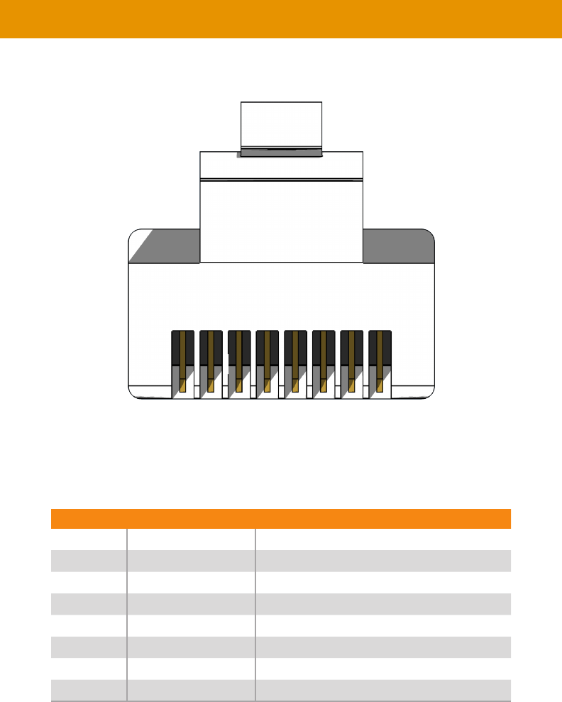
123
Front of RJ-45 Connector
Gefen recommends the TIA/EIA-568-B wiring option. Use the table below when
Pin Color Description
1 Orange / White
2Orange
3 Green / White
4 Blue Unused
5 Blue / White Unused
6 Green RD- (Receive Data, negative differential signal)
7 Brown / White Unused
8 Brown / White Unused
1 2 3 4 5 6 7 8
Network Cable Diagram
Note
Shielded CAT-5e (or better) cabling should be used..
124
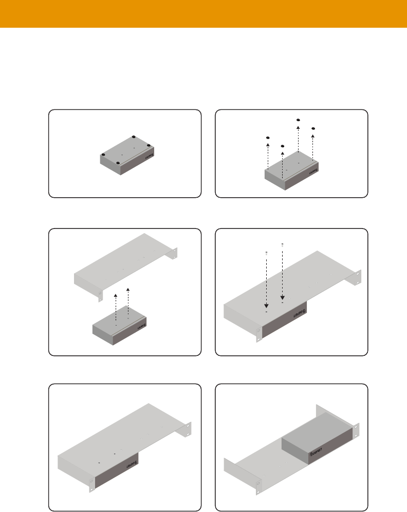
Rack Tray Installation
Gefen 1U Rack Tray
Step 1 Step 2
Step 3 Step 4
Step 5 Step 6
Turn unit upside down. Remove rubber feet.
Line up holes on unit and rack tray. Install countersink screws .
Ensure the unit is installed securely. Unit has been installed into rack tray.

125
Audio •
to 5.1 channels of Bitstream
Connectors & Indicators
• 1 x 3.5mm mini-stereo, female
• 1 x 3.5mm mini-stereo, female
• 1 x
• 1 x
• 1 x RCA-type, female
• 1 x RCA-type, female
• 1 x RJ-45, shielded
• 1 x RJ-45, shielded
• 1 x 3.5mm mini-stereo, female
• 1 x 3.5mm mini-stereo, female
• 1 x 3.5mm mini-stereo, female
• 1 x 5V DC, locking, 5.5mm barrel/2.1mm pin
•
•
Operational
•
Operating Temperature •
Operating Humidity • 5% to 90% RH, non-condensing
•
• 0% to 95% RH, non-condensing
MTBF • 50000 hours
Physical
not including feet and connectors
•
•
All trademarks and registered trademarks are properties of their respective owners.
Specications*

1-707-283-5900 1-800-472-5555
