Pdf Lx Xms 1010P Quick Install Guide User Manual
2017-11-17
User Manual: Manual Pdf Lx-Xms-1010P Quick-Install-Guide pdf_LX-XMS-1010P_quick-install-guide LX-XMS-1010P products
Open the PDF directly: View PDF ![]() .
.
Page Count: 8
Fold Fold Fold
READ ME FIRST
QUICK INSTALL GUIDE
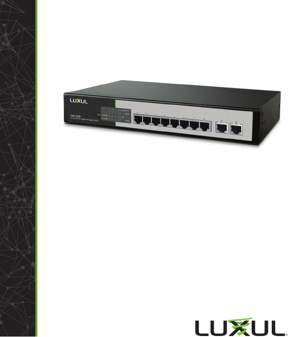
10-Port/8 PoE+ Gigabit
Managed Switch
XMS-1010P
Includes:
XMS-1010P 10-Port/8 PoE+ Gigabit Managed Switch
Rack Mount Kit
Rubber Feet
Power Cord
SETUP AND CONFIGURATION
1Physical Installation
The XMS-1010P can be rack-mounted or used as a desktop switch. Install the
XMS-1010P in a stable/safe place to avoid any possible damage. Make sure there
is adequate space around the XMS-1010P for ventilation and proper heat dissi-
pation; Luxul recommends at least 4-6 inches around all sides. Avoid placement
in direct sunlight. Do not place heavy articles on the XMS-1010P and verify the
ground connection of the outlet is functioning properly.
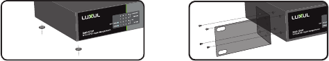
Desktop/Shelf Installation
For desktop/shelf installation, attach the four rubber feet to the corner inden-
tations on the bottom of the XMS-1010P, then place the switch horizontally on
a solid, level platform.
Rack Installation
Use the included L brackets for convenient installation in a 19-inch server or
audio rack. As shown below, use four screws to attach the L-shaped brackets
on either sides of the XMS-1010P, and horizontally insert the switch into the
rack. Use your desired hardware to ax the switch supports to the rack.
Attach feet for desktop installation Install brackets for rack-mounting
2Connecting Ethernet and Power
Ethernet and Power Connections
Use any RJ-45 to connect the XMS-1010P to an Ethernet-enabled device,
including servers, routers or other switches. No crossover cable is necessary.
The XMS-1010P supports 10/100/1000 Mbps Ethernet; 10/100 Mbps half/
full-duplex mode and 1000 Mbps full-duplex mode. All ten RJ-45 ports
support Auto MDI/MDIX and can be used as ordinary ports or as Uplink
ports. Ports 1-8 are PoE+ and are enabled by default.
Use the included power cable to connect the XMS-1010P to a surge protect-
ed outlet. The AC input socket and a power switch are on the rear panel.
The built-in power supply supports 100~240VAC at 50/60Hz.
Network Cabling
Luxul recommends Category-5, super Category-5 or Category-6 unshielded
twisted pair (CAT5/CAT5e/CAT6 UTP). To ensure best performance and
stable data transmission at 1000 Mbps, use Category-6 shielded twisted pair.
cCAUTION: Multiple Uplink channels can create loops, resulting in
network failure. Ensure only one Uplink channel exists
between switches or between the XMS-1010P and a router.
nNOTE: When powering up, the port LEDs corresponding to the opti-
cal interface may take a moment to initialize. This is normal
as the XMS-1010P initialization and startup completes.
nNOTE: The XMS-1010P has an internal 130W power supply. For
optimal switch performance, do not exceed 115W combined
consumption of all external PoE devices.
Sales
801-822-5450
sales@luxul.com
Technical Support
801-822-5450
support@luxul.com
LUX-QIG-XMS-1010P-v7 04131712
Copyright and Trademark Notices
No part of this document may be modified or adapted in any way, for any purposes without permission
in writing from Luxul. The material in this document is subject to change without notice. Luxul reserves
the right to make changes to any product to improve reliability, function, or design. No license is granted,
either expressly or by implication or otherwise under any Luxul intellectual property rights. An implied
license only exists for equipment, circuits and subsystems contained in this or any Luxul product.
© Copyright 2017 Luxul. All rights reserved. The name Luxul, the Luxul logo, the Luxul logo mark and Simply
Connected are all trademarks and or registered trademarks of Luxul Wireless, Inc. All other trademarks and
registered trademarks are property of their respective holders.
Fold Fold Fold
READ ME FIRST
QUICK INSTALL GUIDE
10-Port/8 PoE+ Gigabit
Managed Switch
XMS-1010P
Includes:
XMS-1010P 10-Port/8 PoE+ Gigabit Managed Switch
Rack Mount Kit
Rubber Feet
Power Cord
SETUP AND CONFIGURATION
1Physical Installation
The XMS-1010P can be rack-mounted or used as a desktop switch. Install the
XMS-1010P in a stable/safe place to avoid any possible damage. Make sure there
is adequate space around the XMS-1010P for ventilation and proper heat dissi-
pation; Luxul recommends at least 4-6 inches around all sides. Avoid placement
in direct sunlight. Do not place heavy articles on the XMS-1010P and verify the
ground connection of the outlet is functioning properly.
Desktop/Shelf Installation
For desktop/shelf installation, attach the four rubber feet to the corner inden-
tations on the bottom of the XMS-1010P, then place the switch horizontally on
a solid, level platform.
Rack Installation
Use the included L brackets for convenient installation in a 19-inch server or
audio rack. As shown below, use four screws to attach the L-shaped brackets
on either sides of the XMS-1010P, and horizontally insert the switch into the
rack. Use your desired hardware to ax the switch supports to the rack.
Attach feet for desktop installation Install brackets for rack-mounting
2Connecting Ethernet and Power
Ethernet and Power Connections
Use any RJ-45 to connect the XMS-1010P to an Ethernet-enabled device,
including servers, routers or other switches. No crossover cable is necessary.
The XMS-1010P supports 10/100/1000 Mbps Ethernet; 10/100 Mbps half/
full-duplex mode and 1000 Mbps full-duplex mode. All ten RJ-45 ports
support Auto MDI/MDIX and can be used as ordinary ports or as Uplink
ports. Ports 1-8 are PoE+ and are enabled by default.
Use the included power cable to connect the XMS-1010P to a surge protect-
ed outlet. The AC input socket and a power switch are on the rear panel.
The built-in power supply supports 100~240VAC at 50/60Hz.
Network Cabling
Luxul recommends Category-5, super Category-5 or Category-6 unshielded
twisted pair (CAT5/CAT5e/CAT6 UTP). To ensure best performance and
stable data transmission at 1000 Mbps, use Category-6 shielded twisted pair.
cCAUTION: Multiple Uplink channels can create loops, resulting in
network failure. Ensure only one Uplink channel exists
between switches or between the XMS-1010P and a router.
nNOTE: When powering up, the port LEDs corresponding to the opti-
cal interface may take a moment to initialize. This is normal
as the XMS-1010P initialization and startup completes.
nNOTE: The XMS-1010P has an internal 130W power supply. For
optimal switch performance, do not exceed 115W combined
consumption of all external PoE devices.
Sales
801-822-5450
sales@luxul.com
Technical Support
801-822-5450
support@luxul.com
LUX-QIG-XMS-1010P-v7 04131712
Copyright and Trademark Notices
No part of this document may be modified or adapted in any way, for any purposes without permission
in writing from Luxul. The material in this document is subject to change without notice. Luxul reserves
the right to make changes to any product to improve reliability, function, or design. No license is granted,
either expressly or by implication or otherwise under any Luxul intellectual property rights. An implied
license only exists for equipment, circuits and subsystems contained in this or any Luxul product.
© Copyright 2017 Luxul. All rights reserved. The name Luxul, the Luxul logo, the Luxul logo mark and Simply
Connected are all trademarks and or registered trademarks of Luxul Wireless, Inc. All other trademarks and
registered trademarks are property of their respective holders.

Fold Fold Fold
3 Preparing for Access
IP Addressing
If the XMS-1010P is connected to a network with a 192.168.0.X address
scheme, and your computer shares a similar address on the same network,
you can skip to the next step, Access and Setup.
nNote: If another device on your network shares the 192.168.0.3
address, you’ll need to temporarily reassign or remove that
device while you configure the XMS-1010P.
If your network uses an address scheme other than 192.168.0.X, you’ll need
to set a temporary static IP address on the computer you’re using for
configuration. To do so, set the IP address of your computer to an address
in the 192.168.0.X range, then set the Gateway/Router address to 192.168.0.3
(the default IP address of the XMS-1010P).
Once you’re finished configuring the switch, you can return your comput-
er’s IP configuration to normal, typically “Obtain Automatically/DHCP.”
nNote: Visit http://luxul.com/ip-addressing to learn more about
changing your computer’s IP address and getting connected.
4Access and Setup
Getting Connected
Use an Ethernet cable to connect your computer to the XMS-1010P, then
power on the switch.
Logging In
To access the XMS-1010P web configuration, open your web browser and enter
the switch’s default 192.168.0.3 IP address in the address field. Log in to the
switch using the default user name and password:
Default IP: 192.168.0.3
Username: admin
Password: admin
Select the menu items on the left to view and/or modify the configuration.
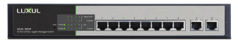
5Hardware Operation
The front panel of the XMS-1010P switch includes eight 10/100/1000 Mbps RJ-45
PoE+ ports, two Gigabit uplink ports, and a set of LED indicators on the left side.
Each 1000 Mbps PoE+ port has one Link/Activity LED, one 1000 Mbps LED and
one PoE LED. There are also two uplink LEDs, one Power LED, one System LED
and a reset button.
XMS-1010P Front Panel
Status indicators
Each port has one Link/Activity LED, one 1000Mbps LED and one PoE LED. In
addition, there are two SFP LEDs, one Power LED, one System LED, and a Reset
button to reboot the device or restore factory default settings. The green LED
indicators show the working status of the switch. The following table describes
the LED functionality:
Indicator State Description
POWER On The XMS-1010P is switched on.
O XMS-1010P is switched o or not connected to AC
power. Check power connections and power switch
at the back of the unit.
Link/Act On There is a device connected to the port.
Flashing Port is receiving or transmitting data.
O No device is connected to the port.
1000 Mbps On A 1000 Mbps-capable device is connected.
O No device is connected and/or the device is not 1000
Mbps-capable.
PoE On A PoE-enabled device is connected and the switch is
supplying power to the device.
O No PoE-enabled device is connected or PoE is not
enabled on this port
SYSTEM On The XMS-1010P is booting.
Flashing The XMS-1010P is running normally.
O The XMS-1010P is in startup and initialization process
or is not on.
At startup, port LEDs will flash for 1 second as a self test.
Reset Button
The Reset button (located at the lower-left corner of the front panel) is
used to reset (or reboot) the switch, or to restore the switch factory
default settings.
XTo Reset the Switch: With the XMS-1010P powered on, press the
Reset button.
cCAUTION: Do not hold the button for more than a second. Doing
so could erase all settings and restore factory defaults.
XTo Restore the Default Settings: With the XMS-1010P powered on, press
and hold the Reset button until the status of the System LED shows the
following: On – flashing – o. Once you see the flash sequence, release
the Reset button and the switch automatically restores factory default
settings. Once the System LED starts flashing again, the XMS-1010P is set
to factory defaults.
cCAUTION: Please note that restoring Default Settings will remove
any/all custom configuration.
Fold Fold Fold
3 Preparing for Access
IP Addressing
If the XMS-1010P is connected to a network with a 192.168.0.X address
scheme, and your computer shares a similar address on the same network,
you can skip to the next step, Access and Setup.
nNote: If another device on your network shares the 192.168.0.3
address, you’ll need to temporarily reassign or remove that
device while you configure the XMS-1010P.
If your network uses an address scheme other than 192.168.0.X, you’ll need
to set a temporary static IP address on the computer you’re using for
configuration. To do so, set the IP address of your computer to an address
in the 192.168.0.X range, then set the Gateway/Router address to 192.168.0.3
(the default IP address of the XMS-1010P).
Once you’re finished configuring the switch, you can return your comput-
er’s IP configuration to normal, typically “Obtain Automatically/DHCP.”
nNote: Visit http://luxul.com/ip-addressing to learn more about
changing your computer’s IP address and getting connected.
4Access and Setup
Getting Connected
Use an Ethernet cable to connect your computer to the XMS-1010P, then
power on the switch.
Logging In
To access the XMS-1010P web configuration, open your web browser and enter
the switch’s default 192.168.0.3 IP address in the address field. Log in to the
switch using the default user name and password:
Default IP: 192.168.0.3
Username: admin
Password: admin
Select the menu items on the left to view and/or modify the configuration.
5Hardware Operation
The front panel of the XMS-1010P switch includes eight 10/100/1000 Mbps RJ-45
PoE+ ports, two Gigabit uplink ports, and a set of LED indicators on the left side.
Each 1000 Mbps PoE+ port has one Link/Activity LED, one 1000 Mbps LED and
one PoE LED. There are also two uplink LEDs, one Power LED, one System LED
and a reset button.
XMS-1010P Front Panel
Status indicators
Each port has one Link/Activity LED, one 1000Mbps LED and one PoE LED. In
addition, there are two SFP LEDs, one Power LED, one System LED, and a Reset
button to reboot the device or restore factory default settings. The green LED
indicators show the working status of the switch. The following table describes
the LED functionality:
Indicator State Description
POWER On The XMS-1010P is switched on.
O XMS-1010P is switched o or not connected to AC
power. Check power connections and power switch
at the back of the unit.
Link/Act On There is a device connected to the port.
Flashing Port is receiving or transmitting data.
O No device is connected to the port.
1000 Mbps On A 1000 Mbps-capable device is connected.
O No device is connected and/or the device is not 1000
Mbps-capable.
PoE On A PoE-enabled device is connected and the switch is
supplying power to the device.
O No PoE-enabled device is connected or PoE is not
enabled on this port
SYSTEM On The XMS-1010P is booting.
Flashing The XMS-1010P is running normally.
O The XMS-1010P is in startup and initialization process
or is not on.
At startup, port LEDs will flash for 1 second as a self test.
Reset Button
The Reset button (located at the lower-left corner of the front panel) is
used to reset (or reboot) the switch, or to restore the switch factory
default settings.
XTo Reset the Switch: With the XMS-1010P powered on, press the
Reset button.
cCAUTION: Do not hold the button for more than a second. Doing
so could erase all settings and restore factory defaults.
XTo Restore the Default Settings: With the XMS-1010P powered on, press
and hold the Reset button until the status of the System LED shows the
following: On – flashing – o. Once you see the flash sequence, release
the Reset button and the switch automatically restores factory default
settings. Once the System LED starts flashing again, the XMS-1010P is set
to factory defaults.
cCAUTION: Please note that restoring Default Settings will remove
any/all custom configuration.

Fold Fold Fold
READ ME FIRST
QUICK INSTALL GUIDE
10-Port/8 PoE+ Gigabit
Managed Switch
XMS-1010P
Includes:
XMS-1010P 10-Port/8 PoE+ Gigabit Managed Switch
Rack Mount Kit
Rubber Feet
Power Cord
SETUP AND CONFIGURATION
1Physical Installation
The XMS-1010P can be rack-mounted or used as a desktop switch. Install the
XMS-1010P in a stable/safe place to avoid any possible damage. Make sure there
is adequate space around the XMS-1010P for ventilation and proper heat dissi-
pation; Luxul recommends at least 4-6 inches around all sides. Avoid placement
in direct sunlight. Do not place heavy articles on the XMS-1010P and verify the
ground connection of the outlet is functioning properly.
Desktop/Shelf Installation
For desktop/shelf installation, attach the four rubber feet to the corner inden-
tations on the bottom of the XMS-1010P, then place the switch horizontally on
a solid, level platform.
Rack Installation
Use the included L brackets for convenient installation in a 19-inch server or
audio rack. As shown below, use four screws to attach the L-shaped brackets
on either sides of the XMS-1010P, and horizontally insert the switch into the
rack. Use your desired hardware to ax the switch supports to the rack.
Attach feet for desktop installation Install brackets for rack-mounting
2Connecting Ethernet and Power
Ethernet and Power Connections
Use any RJ-45 to connect the XMS-1010P to an Ethernet-enabled device,
including servers, routers or other switches. No crossover cable is necessary.
The XMS-1010P supports 10/100/1000 Mbps Ethernet; 10/100 Mbps half/
full-duplex mode and 1000 Mbps full-duplex mode. All ten RJ-45 ports
support Auto MDI/MDIX and can be used as ordinary ports or as Uplink
ports. Ports 1-8 are PoE+ and are enabled by default.
Use the included power cable to connect the XMS-1010P to a surge protect-
ed outlet. The AC input socket and a power switch are on the rear panel.
The built-in power supply supports 100~240VAC at 50/60Hz.
Network Cabling
Luxul recommends Category-5, super Category-5 or Category-6 unshielded
twisted pair (CAT5/CAT5e/CAT6 UTP). To ensure best performance and
stable data transmission at 1000 Mbps, use Category-6 shielded twisted pair.
cCAUTION: Multiple Uplink channels can create loops, resulting in
network failure. Ensure only one Uplink channel exists
between switches or between the XMS-1010P and a router.
nNOTE: When powering up, the port LEDs corresponding to the opti-
cal interface may take a moment to initialize. This is normal
as the XMS-1010P initialization and startup completes.
nNOTE: The XMS-1010P has an internal 130W power supply. For
optimal switch performance, do not exceed 115W combined
consumption of all external PoE devices.
Sales
801-822-5450
sales@luxul.com
Technical Support
801-822-5450
support@luxul.com
LUX-QIG-XMS-1010P-v7 04131712
Copyright and Trademark Notices
No part of this document may be modified or adapted in any way, for any purposes without permission
in writing from Luxul. The material in this document is subject to change without notice. Luxul reserves
the right to make changes to any product to improve reliability, function, or design. No license is granted,
either expressly or by implication or otherwise under any Luxul intellectual property rights. An implied
license only exists for equipment, circuits and subsystems contained in this or any Luxul product.
© Copyright 2017 Luxul. All rights reserved. The name Luxul, the Luxul logo, the Luxul logo mark and Simply
Connected are all trademarks and or registered trademarks of Luxul Wireless, Inc. All other trademarks and
registered trademarks are property of their respective holders.
