Marposs E86NP Wireless Industrial Telemeter System User Manual D31019BM70
Marposs SpA Wireless Industrial Telemeter System D31019BM70
Marposs >
Contents
- 1. Users Manual Part 1
- 2. Users Manual Part 2
Users Manual Part 1

E86N - SISTEMA TOUCH CON TRASMISSIONE RADIO
Manualed’installazione e uso ………………………………………..… 5
E86N - TOUCH SYSTEM WITH RADIO TRANSMISSION
Installation and user manual …………………………………………… 49
E86N - SCHALTSYSTEM MIT FUNK-ÜBERTRAGUNG
Installations- und Bedienungsanleitung …………………………….... 93
E86N - DETECTEUR TOUCH A TRANSMISSION RADIO
Manuel d’installation et d’utilisation ……………………….………..… 137
E86N - SISTEMA TOUCH CON TRANSMISIÓN RADIO
Manual de instalación y uso ………………..………………………….. 181
Manual code: D31019BM70

E86N - TOUCH SYSTEM WITH RADIO TRANSMISSION
2
Manufacturer : MARPOSS S.p.A.
Address : Via Saliceto, 13 – 40010 Bentivoglio (BO) – Italy
www.marposs.com
Manual code : D31019BM70
Issued by : MARPOSS S.p.A. (UTD/MU)
Issue date : 09.2004
Edition : (01) November 2005
MARPOSS S.p.A. is not obliged to notify customers of changes to the product.
The descriptions in this manual in no way authorise tampering by unauthorised personnel.
Any tampering with the equipment will immediately invalidate the warranty.
© Marposs S.p.A. 2004-2005
mida 3
E86N - TOUCH SYSTEM WITH RADIO TRANSMISSION
4
Waste Electrical and Electronic Equipment (WEEE) Directive
The product and any part that can be mechanically separated from it must not
be disposed of the environment and must not be disposed of as municipal or
general waste (Law for national adoption of European directives 2002/95/EC
and 2002/96/EC and others). The provisions of the law only apply to products
identified as WEEE (waste electrical and electronic equipment) marked with the appropriate
symbol and in any case put on the market after 13 August 2005.
Once put out of use, the WEEE product may contain substances and parts that are harmful to
human health and the environment and which must be subject to professional treatment for
reuse, recycling or definitive disposal.
Deliver the WEEE product to an authorised WEEE treatment centre, or contact the local
organisation responsible or your nearest Marposs service centre for information.
Illegal disposal of a WEEE product is a crime punishable by penalties.
2002/95/CE
2002/96/CE

mida 5
E86N
SISTEMA TOUCH CON TRASMISSIONE RADIO
Manuale d’installazione e uso
ITALIANO
E86N- Sistema touch con trasmissione radio
6
Del prodotto e di ogni parte meccanicamente separabile da esso sono vietati la
dispersione nell’ambiente e lo smaltimento come rifiuto urbano o generico (Legge di
recepimento nazionale delle direttive europee 2002/95/CE e 2002/96/CE ed altri).
Le disposizioni di legge si applicano solo ai prodotti identificati RAEE con l’apposito
logo e comunque immessi sul mercato dal 13 agosto 2005.
Il prodotto RAEE una volta dismesso può contenere sostanze e parti dannose per l’uomo e per
l’ambiente che devono ricevere un trattamento professionale ai fini del reimpiego, riciclaggio e
smaltimento definitivo.
Consegnare il prodotto RAEE ad un centro autorizzato per il trattamento RAEE, oppure contattare l’ente
locale preposto o il centro di assistenza Marposs più vicino per informazioni.
Lo smaltimento abusivo di un prodotto RAEE è un reato punito da sanzioni. 2002/95/CE
2002/96/CE
MARPOSS S.p.A. non assume l'obbligo di notificare eventuali modifiche al prodotto.
Le descrizioni riportate nel presente manuale non autorizzano in alcun modo manomissioni da parte di personale non autorizzato.
La garanzia sulle apparecchiature decade nel momento in cui tali manomissioni vengano riscontrate.

mida 7
Indice
1. NORME ED AVVERTENZE GENERALI.................................................................................................................................................. 9
2. COMPONENTI DEL SISTEMA .............................................................................................................................................................. 10
3. CONFIGURAZIONE E FUNZIONAMENTO ........................................................................................................................................... 11
4. MODALITA’ D’IMPIEGO........................................................................................................................................................................ 12
5. SONDA DI MISURA E TRASMETTITORE COMPATTO E86N-P......................................................................................................... 13
6. TRASMISSIONE RADIO........................................................................................................................................................................ 14
6.1 Descrizione .................................................................................................................................................................................... 14
6.1.1 Distanze di utilizzo per più sistemi........................................................................................................................................... 14
6.2 Attivazione della trasmissione........................................................................................................................................................ 15
6.2.1 Attivazione radio ...................................................................................................................................................................... 15
6.2.2 Attivazione meccanica............................................................................................................................................................. 15
6.3 Disattivazione della trasmissione................................................................................................................................................... 15
6.3.1 Trasmettitore con attivazione radio ......................................................................................................................................... 15
6.3.2 Trasmettitore con attivazione meccanica ................................................................................................................................ 15
7. TRASMETTITORE E86N ....................................................................................................................................................................... 16
7.1 Descrizione .................................................................................................................................................................................... 16
7.2 Durata della batteria e indicazioni sull’Interfaccia.......................................................................................................................... 17
7.3 Dimensioni trasmettitore con sonde............................................................................................................................................... 18
7.3.1 Trasmettitore standard con flangia standard ........................................................................................................................... 18
7.3.2 Trasmettitore standard con flangia di regolazione................................................................................................................... 19
7.4 Dimensioni trasmettitore compatto ................................................................................................................................................ 20
7.4.1 Trasmettitore compatto E86N-P .............................................................................................................................................. 20
Trasmettitore compatto E86N-P senza codolo conico ......................................................................................................................... 20
8. RICEVITORE E86N................................................................................................................................................................................ 21
8.1 Descrizione Antenna e prolunga con connettore........................................................................................................................... 21
8.2 Modalità display remoto................................................................................................................................................................. 21
8.3 Collegamento dell'antenna............................................................................................................................................................. 21
8.4 Montaggio dell'antenna.................................................................................................................................................................. 22
9. UNITA’ DI INTERFACCIA E86N............................................................................................................................................................ 23
Pannello frontale unità di interfaccia ....................................................................................................................................................... 23
9.2 Dimensioni unita' dell'interfaccia .................................................................................................................................................... 24
9.3 Caratteristiche tecniche Interfaccia E86N...................................................................................................................................... 24
9.4 Collegamenti all’unità di interfaccia................................................................................................................................................ 25
9.4.1 Selezione del codice di identificazione.................................................................................................................................... 25
9.5 Diagramma I/O unità di interfaccia E86N....................................................................................................................................... 26
10. PROGRAMMAZIONE DEL SISTEMA ................................................................................................................................................. 27
10.1 Programmazione dell'interfaccia.................................................................................................................................................... 28
10.2 Programmazione del Trasmettitore................................................................................................................................................ 31
10.3 Programmazione del trasmettitore in modalità Recovery .............................................................................................................. 33
10.4 Analisi occupazione dello spettro elettromgnetico (Funzione “Sniffer”)......................................................................................... 34
10.4.1 Scansione................................................................................................................................................................................ 35
10.4.2 Visualizzazione dei risultati...................................................................................................................................................... 35
11. MONTAGGIO SONDA – TRASMETTITORE STANDARD ................................................................................................................. 36
11.1 Montaggio sonda – trasmettitore standard .................................................................................................................................... 36
11.2 Inserimento prolunghe per sonde (optional) .................................................................................................................................. 37
12. MONTAGGIO DEL TRASMETTITORE ............................................................................................................................................... 38
12.1 Montaggio del trasmettitore Standard sul cono ............................................................................................................................. 38
12.2 Montaggio trasmettitore Standard sul cono con flangia di regolazione ......................................................................................... 39
12.3 Montaggio trasmettitore compatto E86N-P sul cono ..................................................................................................................... 41
12.3.1 Fissaggio trasmettitore E86N-P al cono (lavorazione del cono).............................................................................................. 41
12.3.2 Fissaggio al cono del trasmettitore E86N-P senza codolo conico (lavorazione del cono) ...................................................... 41
13. MONTAGGIO DEL BRACCETTO ....................................................................................................................................................... 42
14. DIAGNOSTICA..................................................................................................................................................................................... 43
14.1 Messaggi di errore ......................................................................................................................................................................... 43
14.2 Segnalazione dei Led .................................................................................................................................................................... 43
15. MANUTENZIONE................................................................................................................................................................................. 44
15.1 manutenzione ordinaria ................................................................................................................................................................. 44
15.1.1 Pulizia e controlli...................................................................................................................................................................... 44
15.1.2 Inserimento/Sostituzione Batteria Trasmettitore...................................................................................................................... 44

ITALIANO
E86N- Sistema touch con trasmissione radio
8
15.2 Manutenzione straordinaria............................................................................................................................................................ 45
15.2.1 Sostituzione spina di rottura/braccetto..................................................................................................................................... 45
15.2.2 Sostituzione guarnizione esterna............................................................................................................................................. 45
15.2.3 Sostituzione sonda/trasmettitore ............................................................................................................................................. 45
16. Accessori............................................................................................................................................................................................. 46
16.1 Gruppo supporto aria di pulizia per Trasmettitore Compatto ......................................................................................................... 46
17. LISTA RICAMBI ................................................................................................................................................................................... 47
mida 9
1. NORME ED AVVERTENZE GENERALI
PREMESSA
Questo manuale d’istruzione fornisce tutte le informazioni specifiche necessarie alla conoscenza e al corretto utilizzo
dell'apparecchiatura MARPOSS in Vostro possesso.
Le descrizioni contenute in questo manuale sono indirizzate al seguente tipo di personale:
• Personale MARPOSS o del Cliente che deve effettuare l'installazione dell'apparecchiatura.
• Personale tecnico del Cliente che deve operare direttamente con l'apparecchiatura MARPOSS.
• Personale tecnico del Cliente responsabile della manutenzione della linea produttiva in cui viene installata l'apparecchiatura
MARPOSS.
TUTTI I DIRITTI SONO RISERVATI. QUESTO MANUALE È DESTINATO SOLO ALL'USO INTERNO DA PARTE DEL CLIENTE. OGNI ALTRO USO È PROIBITO.
COLLAUDO E GARANZIA
I difetti nei materiali sono coperti da garanzia con le seguenti limitazioni:
• DURATA DELLA GARANZIA: la garanzia copre il prodotto e tutte le riparazioni effettuate entro i termini concordati.
• OGGETTO DELLA GARANZIA: la garanzia si applica al prodotto ed alle sue parti contrassegnate dal numero di matricola o altro
numero d’identificazione usato da MARPOSS.
La garanzia sopra descritta è valida a meno di accordi diversi fra MARPOSS e Cliente.
NORME DI SICUREZZA GENERALI
L'apparecchiatura è stata costruita in conformità alle norme CEI EN60950.
CONVENZIONI E SIMBOLI UTILIZZATI
Nella stesura del manuale sono state adottate alcune modalità tipografiche.
In dettaglio, sono stati definiti due tipi di avviso di sicurezza:
Avvertenza:
Questa segnalazione indica la possibilità di danneggiamento per l'unità elettronica e per altri dispositivi ad essa collegati,
oppure la possibilità di perdere dati.
Attenzione:
Questa segnalazione indica condizioni di rischio per l'operatore o per il tecnico.
Le informazioni di particolare importanza che possono facilitare la comprensione e l'utilizzo del sistema sono incasellate in un
riquadro, contrassegnato da "Nota", e in carattere grassetto.
ITALIANO
E86N- Sistema touch con trasmissione radio
10
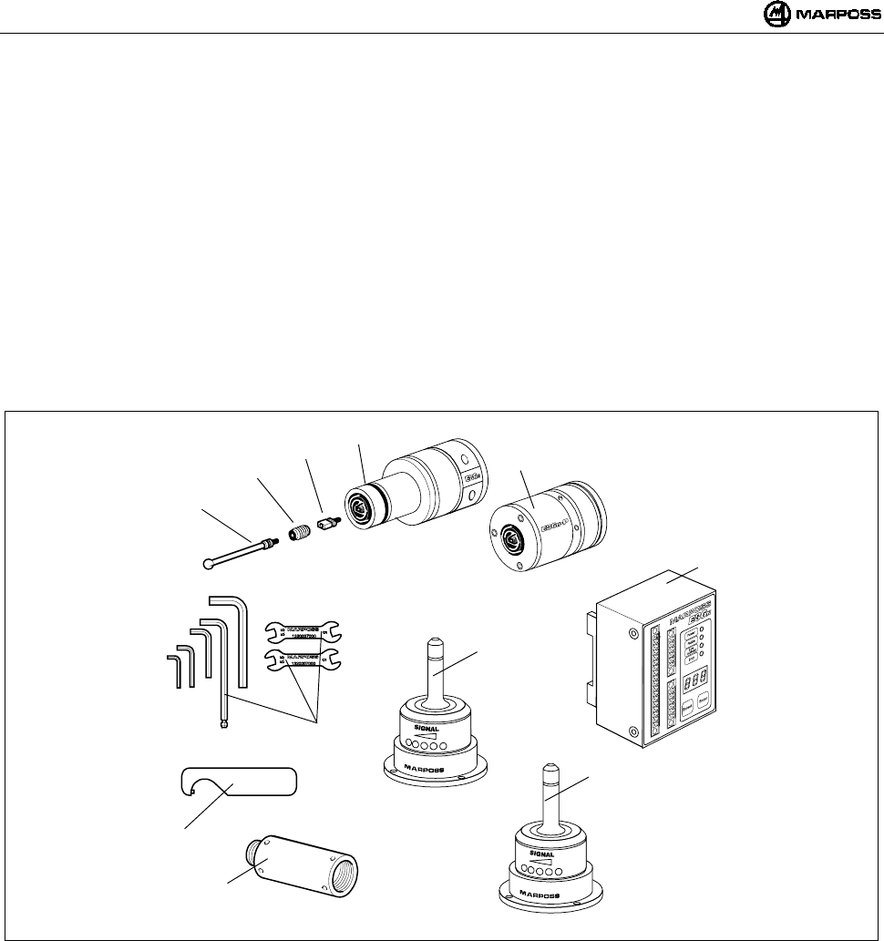
2. COMPONENTI DEL SISTEMA
A1 - Sonda e trasmettitore E86N (standard)
A2 - Trasmettitore E86N-P (compatto)
B - Spina di rottura (optional)
C - Ritegno braccetto (optional)
D - Braccetto
E - Antenna
F - Unità di interfaccia E86N
G - Due chiavi aperte CH 5 - 5.5 e kit chiavi esagonali
H - Una chiave speciale per sonda T25 e prolunghe meccaniche
I - Prolunghe per sonde (optional)
L - Antenna ausiliaria (optional)
Figura 2-1. Componenti del sistema.
A1
B
C
D
E
G
F
H
I
L
A2

mida 11
3. CONFIGURAZIONE E FUNZIONAMENTO
Il sistema touch con trasmissione radio serve ad identificare dei punti nello spazio che, elaborati da CNC della macchina utensile,
determinano delle misurazioni. Detti punti vengono rilevati dalla sonda, microinterruttore multidirezionale di precisione, e inviati tramite il
sistema di trasmissione radio, composto da un trasmettitore e un ricevitore, all’unità di interfaccia e da questa adattati al CNC. Il ciclo di
misura richiama dal magazzino utensili il gruppo sonda/trasmettitore montato sul portautensile e lo inserisce nel mandrino. Il sistema è
facile da utilizzare ed è progettato per lavorare negli ambienti industriali più ostili. Viene utilizzato su centri di lavorazione e fresatrici per:
l’identificazione, il posizionamento, la misurazione del pezzo da lavorare e la misurazione del pezzo lavorato.
L’applicazione tipica del sistema è costituita da:
A - Pezzo da misurare E - Mandrino macchina utensile
B - Braccetto F - Antenna E86N
C - Sonda touch G - Unità di interfaccia E86N
D - Trasmettitore E86N H - CNC della macchina utensile
Figura 3-1. Configurazione e funzionamento.
BA
C
D
E
F
G
H
ITALIANO
E86N- Sistema touch con trasmissione radio
12
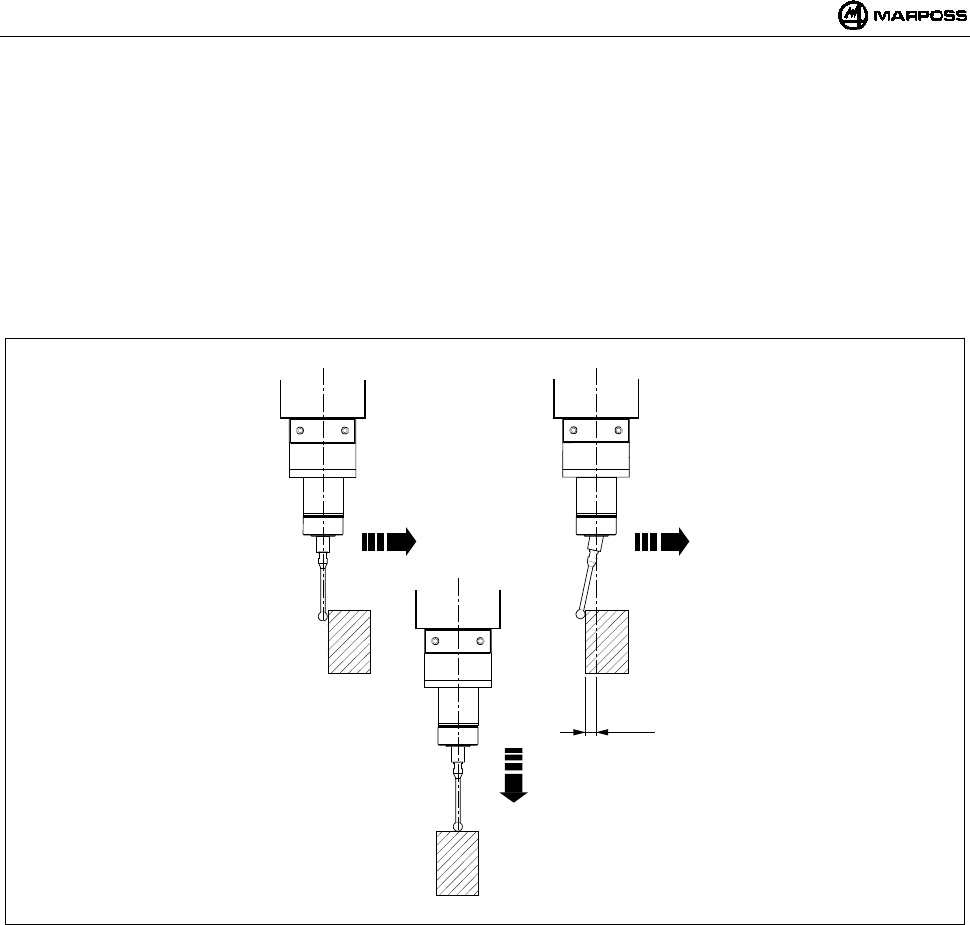
4. MODALITA’ D’IMPIEGO
Il sistema di misurazione è multidirezionale nell’emisfero x/y/+z.
Il contatto del braccetto con la superficie del pezzo da ispezionare genera un segnale utilizzato dalla macchina utensile per
memorizzare il punto di contatto e per arrestare gli assi di macchina. Per avere una buona ripetibilità del sistema si consiglia di
utilizzare una velocità di misura costante.
La velocità di misura scelta deve consentire un arresto dell’asse macchina entro i limiti di extracorsa della sonda utilizzata.
Prima di utilizzare la sonda occorre compensare l’errore sistematico di misura del sistema composto da sonda, macchina utensile
e CNC eseguendo una calibrazione. L’errore sistematico è caratteristico di ogni direzione di misura e ripetibile, perciò la
calibrazione deve essere effettuata in ogni direzione in cui si rileverà la misura. Per calibrare il sistema si consiglia di misurare dei
punti in macchina di valore noto (R) e calcolare le differenze fra questi e i valori misurati (R+K1). Tale differenza (K1) va inserita
nei parametri correttori utensili del CNC e richiamata ogni volta che si esegue una misura nella stessa direzione.
Figura 4-1. Modalità d’impiego.
X/Y X/Y
Z
mida 13
5. SONDA DI MISURA E TRASMETTITORE COMPATTO E86N-P
La sonda di misura è un microinterruttore multidirezionale di precisione utilizzata nelle applicazioni su macchine ad asportazione di
truciolo a CN, per il controllo e la misura di utensili e pezzi.
Sono disponibili diversi modelli di sonde touch multidirezionali nell’emisfero x/y/+z.
Per alcuni modelli di sonda esistono due differenti versioni a seconda del tipo di protezione frontale:
• “Versione G” con guarnizione telata per una migliore protezione contro il liquido refrigerante.
• “Versione S” con scudo metallico di protezione ai trucioli.
Per risolvere in modo ottimale le specifiche esigenze che si manifestano sulle differenti macchine utensili, sono disponibili le seguenti
sonde:
Sonda T25G / T25S
Sonda TL25G / TL25S
Sonda T36G / T36S
Sonda T60G / T60S
Sonda TT25 (solo con guarnizione)
Sonda TT25H (solo con guarnizione)
Sonda TT60 (solo con guarnizione)
Tabella 5-1. Caratteristiche tecniche della sonda.
Tipo sonda T25 TL25 T36 T60 TT25 TT25H TT60
Assi sonda ±X, ±, Y+Z±X, ±Y, +Z±X, ±Y, +Z±X, ±Y,+Z±X, ±Y,+Z±X, ±Y,+Z±X, ±Y,+Z
Ripetibilità unidirezionale sonda (2 σ)
con velocità fino a 600 mm/min.
0,5 µm0,5 µm0,5 µm1 µm1 µm2 µm1 µm
Forza di misura nel piano X, Y 200 gf 90 gf 260 gf 280 gf 50-95 gf 90-175 gf 70-120 gf
Forza di misura nella direzione Z 1200 gf 550 gf 1200 gf 1200 gf 580 gf 1080 gf 580 gf
Extracorsa nel piano X, Y 11,2 mm 11,2 mm 14,4 mm 22 mm 11,6 mm 11,6 mm 19 mm
Extracorsa nella direzione Z4 mm 4 mm 4,2 mm 6,4 mm 4 mm 4 mm 6,4 mm
CARATTERISTICHE RIFERITE AL BRACCETTO DI 35 mm 35 mm 40 mm 50 mm 35 mm 35 mm 50 mm
Grado di protezione secondo norme IEC IP67 IP67 IP67 IP67 IP67 IP67 IP67
A differenza del trasmettitore Standard, sul quale può essere montata una qualsiasi delle sonde di misura elencate nella Tabella 5-1, il
trasmettitore Compatto E86N-P incorpora la sonda e le sue caratteristiche tecniche sono le seguenti:
Tabella 5-2. Caratteristiche tecniche del trasmettitore compatto.
Assi ±X, ±, Y+Z
Ripetibilità unidirezionale (2 σ) con velocità fino a 600 mm/min. 0,5 µm
Forza di misura nel piano X, Y 200 gf
Forza di misura nella direzione Z 1200 gf
Extracorsa nel piano X, Y 11,2 mm
Extracorsa nella direzione Z4 mm
CARATTERISTICHE RIFERITE AL BRACCETTO DI 35 mm
Grado di protezione secondo norme IEC IP68
ITALIANO
E86N- Sistema touch con trasmissione radio
14
6. TRASMISSIONE RADIO
6.1 Descrizione
Il sistema di trasmissione radio è composto da tre elementi:
Trasmettitore: emette le informazioni necessarie al CNC per
l'elaborazione della misura.
Antenna: riceve il segnale del trasmettitore e lo invia all'unità
d’interfaccia E86N.
Unità d’interfaccia: elabora i segnali e li converte in una forma
utilizzabile dal CNC.
Il sistema E86N permette la programmazione di 64 diversi canali di
trasmissione mediante tastiera sull’interfaccia (vedi capitolo 10
"PROGRAMMAZIONE DEL SISTEMA” a pag. 27)
Per aumentare il campo di trasmissione e l'affidabilità della
comunicazione radio, è possibile collegare due antenne all unità
d’interfaccia E86N.
Il sistema permette di utilizzare fino ad un massimo di 4 trasmettitori
sulla stessa macchina utensile (Figura 6-1), funzionanti sullo stesso
canale e attivabili alternativamente, uno alla volta, mediante un
differente codice di identificazione (vedi paragrafo 10.2
“Programmazione del Trasmettitore" a pag. 31).
Figura 6-1. Sistema di trasmissione radio.
Tabella 6-1. Caratteristiche tecniche.
-Distanza di trasmissione : 15 m -Potenza di attivazione : <10 mW
-Potenza di trasmissione : <1mW -Numero canali di trasmissione : 64
-Distanza di attivazione,
disattivazione e programmazione
: 5 m -Frequenza di trasmissione :433,075÷434,775 Mhz
Tabella 6-2. Frequenze di trasmissione.
CANALE FREQUENZA CANALE FREQUENZA CANALE FREQUENZA CANALE FREQUENZA
1 433,075 17 433,475 33 434,000 49 434,400
2 433,100 18 433,500 34 434,025 50 434,425
3 433,125 19 433,525 35 434,050 51 434,450
4 433,150 20 433,550 36 434,075 52 434,475
5 433,175 21 433,575 37 434,100 53 434,500
6 433,200 22 433,600 38 434,125 54 434,525
7 433,225 23 433,625 39 434,150 55 434,550
8 433,250 24 433,650 40 434,175 56 434,575
9 433,275 25 433,675 41 434,200 57 434,600
10 433,300 26 433,700 42 434,225 58 434,625
11 433,325 26 433,725 43 434,250 59 434,650
12 433,350 28 433,750 44 434,275 60 434,675
13 433,375 29 433,775 45 434,300 61 434,700
14 433,400 30 433,800 46 434,325 62 434,725
15 433,425 31 433,825 47 434,350 63 434,750
16 433,450 32 433,850 48 434,375 64 434,775
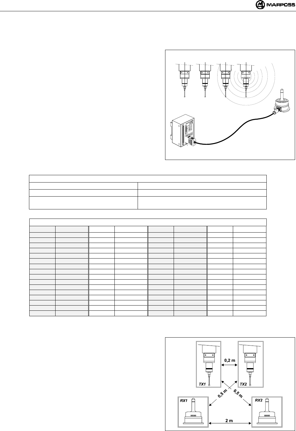
6.1.1 Distanze di utilizzo per più sistemi
Per evitare interferenze tra sistemi posti nelle vicinanze devono essere
rispettate le seguenti distanze:
Almeno 2 metri tra le Antenne dei sistemi, indipendentemente
dall’utilizzo di canali adiacenti (es. CH5 e CH6) o meno.
Almeno 0,2 metri tra i Trasmettitori dei sistemi, indipendentemente
dall’utilizzo di canali adiacenti o meno.
Almeno 0,5 metri tra il trasmettitore di un sistema e l’Antenna
dell’altro funzionanti su canali adiacenti.
NOTA: nel caso di utilizzo di 2 sistemi sulla stessa macchina
(es. centri di lavoro a doppio mandrino), oltre ad attenersi
alle distanze indicate in Figura 6-2, si devono utilizzare
due canali NON adiacenti e codici di identificazione “A” e
“D”.
La distanza tra sistemi operanti sullo stesso canale deve essere
superiore a 100 metri.
Figura 6-2. Distanze di utilizzo per più sistemi.
ABCD
mida 15
6.2 Attivazione della trasmissione
Il trasmettitore è normalmente in condizione di attesa (stand-by); l’attivazione della trasmissione può avvenire in due modi a seconda
della versione di trasmettitore:
•attivazione radio
•attivazione meccanica (solo per Trasmettitore Standard)
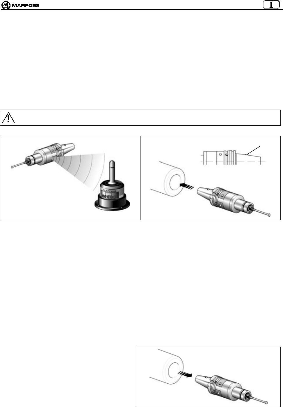
6.2.1 Attivazione radio
L’attivazione del sistema avviene a seguito dell’invio di un segnale radio dall'antenna al trasmettitore. Il comando di attivazione del
sistema (START) è generato dall'unità di interfaccia in 2 modi:
mediante il collegamento del segnale di ingresso START/STOP alla logica di macchina (codice M).
da tastiera mediante la pressione (per almeno 2 secondi) del tasto <select>
6.2.2 Attivazione meccanica
Sul cono portautensile è presente un microinterruttore (H). L’inserimento del cono nel mandrino causa l’attivazione della trasmissione.
Avvertenza:
Quando si ripone il trasmettitore nel magazzino utensili assicurarsi che non venga azionato il microinterruttore di attivazione.
Figura 6-3. Attivazione radio. Figura 6-4. Attivazione meccanica.
6.3 Disattivazione della trasmissione
La disattivazione della trasmissione può avvenire in diversi modi a seconda della versione di Trasmettitore.
6.3.1 Trasmettitore con attivazione radio
DISATTIVAZIONE RADIO:
1. Logica di macchina
La disattivazione avviene mediante comando di macchina sull’ingresso START/STOP (codice M).
2. Da Tastiera
mediante la pressione (per almeno 2 secondi) del tasto <select>
DISATTIVAZIONE AUTOMATICA
La disattivazione avviene allo scadere del tempo impostato sul timer del trasmettitore
(vedere paragrafo 10.2 “Programmazione del Trasmettitore" a pag. 31).
6.3.2 Trasmettitore con attivazione meccanica
DISATTIVAZIONE MECCANICA
La disattivazione avviene quando il trasmettitore viene
estratto dal mandrino.
DISATTIVAZIONE AUTOMATICA
La disattivazione avviene allo scadere del tempo
impostato sul timer del trasmettitore
(vedere paragrafo 10.2 “Programmazione del
Trasmettitore" a pag. 31)
Figura 6-5. Esempio di disattivazione meccanica.
H
ITALIANO
E86N- Sistema touch con trasmissione radio
16
7. TRASMETTITORE E86N
7.1 Descrizione
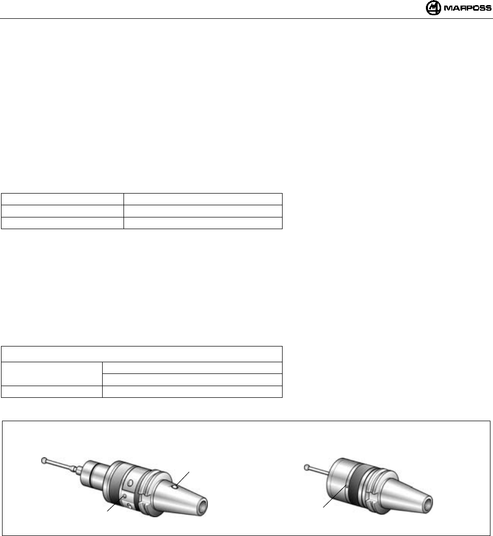
Attualmente esistono due tipi di trasmettitore:
• TRASMETTITORE STANDARD
sul quale vanno fissate, mediante opportune flange, i vari tipi di sonda
• TRASMETTITORE COMPATTO
La sonda è contenuta all’interno del Trasmettotore
Il trasmettitore invia all'antenna le seguenti informazioni necessarie al CNC per l’elaborazione della misura:
• Stato della sonda: sonda con braccetto a riposo/sonda con braccetto deflesso
• Stato della batteria: carica o quasi scarica
Un LED verde (L) indica lo stato della sonda, della batteria e della trasmissione:
LED acceso permanente = Sonda con braccetto deflesso
1 impulso ogni 2s = Trasmissione attivata
2 impulsi ogni 2s = Batteria quasi scarica
I Trasmettitori Standard, si suddividono a loro volta in:
• TRASMETTITORI CON ATTIVAZIONE RADIO:
La trasmissione viene attivata da un segnale inviato dall'antenna.
• TRASMETTITORI CON ATTIVAZIONE MECCANICA:
La trasmissione viene attivata mediante il microinterruttore (H) posto sul cono portautensili.
Il microinterruttore non è presente nel trasmettitore con attivazione radio.
ATTENZIONE: L’attivazione meccanica è prevista solo sui trasmettitori Standard e non su quelli compatti.
Per la programmazione del Trasmettitore vedere paragrafo 10.2 “Programmazione del Trasmettitore" a pag. 31.
Tabella 7-1. Caratteristiche tecniche.
Alimentazione: : batteria 9V (trasmettitore standard)
: 6 batterie 1,5 V (trasmettitore compatto)
Distanza di trasmissione : 15m
Figura 7-1. Trasmettitori.
Trasmettitore Standard Trasmettitore Compatto
H
LL
mida 17
7.2 Durata della batteria e indicazioni sull’Interfaccia
Lo stato di carica delle batterie del Trasmettitore viene segnalato sull’Interfaccia, sia dai relativi Led (Led Low Battery o Led Error) che
sul display (a sistema attivato premendo il tasto <select> si visualizza sulla sinistra il codice di Identificazione e a destra il livello di
carica (“7” valore Max e “0” batteria completamente scarica). In particolare se si verifica quanto segue:
• Il Led “Low battery” si accende in corrispondenza del Livello “3” sul display
• Il Led “Error” si accende in corrispondenza del Livello “0” sul display
Il valore di carica visualizzato sul display rimane memorizzato fino alla successiva attivazione.
La durata della batteria dipende dal tempo di utilizzo del trasmettitore e dal tipo di batteria utilizzata. Nella tabella sono riportati i valori di
durata in funzione della batteria e in condizione di funzionamento continuo e stand-by del trasmettitore:
Trasmettitore standard
TIPO BATTERIA BATTERIA CONSIGLIATA FUNZIONAMENTO CONTINUO FUNZIONAMENTO STAND-BY
Alcalina DURACELL MN1604
DURACELL PC1604 PROCELL
ENERGIZER X22
ENERGIZER 522
150 ore 170 giorni
Litio ENERGIZER L522
ULTRALIFE U9VL
DURACELL PL1604
SONNENSCHEIN SLM9-J
320 ore 380 giorni
Nota: Una batteria alcalina è fornita con il trasmettitore all interno dell'imballo. Inserire la batteria nel trasmettitore prima
dell’installazione (vedere paragrafo 15.1.2 “Inserimento/Sostituzione Batteria Trasmettitore” a pag. 44).
Avvertenza:
TRASMETTITORE CON ATTIVAZIONE MECCANICA
Verificare che la sede del cono nel magazzino utensili abbia una conformazione tale da evitare l’azionamento del
microinterruttore (H) di attivazione.
BATTERIE AL LITIO: le batterie al litio possono esplodere se non sostituite in modo corretto. Sostituire solo con tipo
uguale o equivalenti (vedi tabella). Eliminare le batterie usate in conformità con le normative vigenti.
Trasmettitore compatto
TIPO BATTERIA BATTERIA CONSIGLIATA FUNZIONAMENTO CONTINUO FUNZIONAMENTO STAND-BY
DURACELL MN9100
Alcalina
ENERGIZER E90 230 ore 250 giorni
Nota: le batterie sono fornite con il trasmettitore all interno dell'imballo.
Inserire le batterie nel trasmettitore prima dell’installazione (vedere paragrafo 15.1.2 “Inserimento/Sostituzione
Batteria Trasmettitore” a pag. 44).
ITALIANO
E86N- Sistema touch con trasmissione radio
18
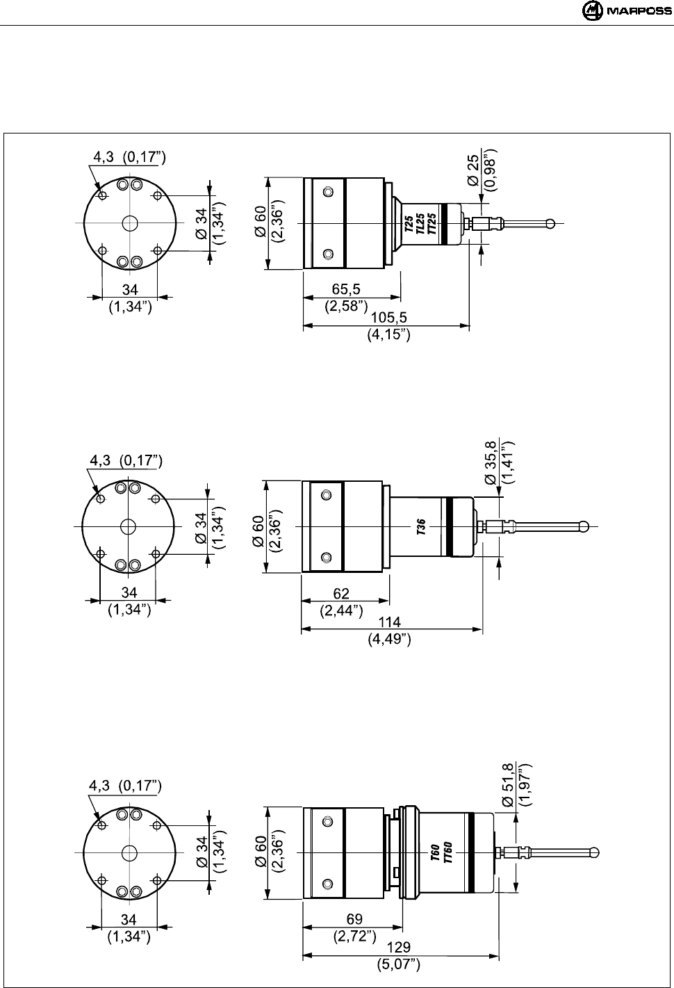
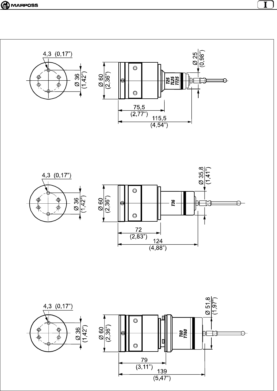
7.3 Dimensioni trasmettitore con sonde
7.3.1 Trasmettitore standard con flangia standard
Figura 7-2. Ingombri trasmettitore con flangia standard.
mida 19
7.3.2 Trasmettitore standard con flangia di regolazione
Figura 7-3. Ingombri trasmettitore con flangia di regolazione.

ITALIANO
E86N- Sistema touch con trasmissione radio
20
7.4 Dimensioni trasmettitore compatto
7.4.1 Trasmettitore compatto E86N-P
Figura 7-4
7.4.2 Trasmettitore compatto E86N-P senza codolo conico
Figura 7-5
N°3 VITI M4X6
N°3 VITI M4X6

mida 21
8. RICEVITORE E86N
8.1 Descrizione Antenna e prolunga con connettore
L'antenna riceve i dati emessi dal trasmettitore e li invia all’unità di interfaccia E86N alla quale va collegata mediante il cavo con
connettore.
Sulla parte anteriore dell'antenna si trovano:
A- Un LED rosso. Acceso indica che la trasmissione non è in atto oppure che il segnale del trasmettitore non è ricevuto.
B- Un LED giallo e tre LED verdi. Indicano l'intensità del segnale ricevuto. L’accensione dei LED facilita, in sede di installazione,
il corretto posizionamento dell'antenna.
C- Cavo schermato con connettore (di lunghezza 15m o 30m) per il collegamento all’unità di interfaccia E86N.
Figura 8-1: Antenna e cavo con connettore.
8.2 Modalità display remoto
I led presenti sull’Antenna possono inoltre funzionare come display remoto dell’unità d’Interfaccia, qualora in fase di di programmazione
dell’interfaccia venga opportunamente programmato il dato “rd” (remote display) (vedi paragrafo 10.1 Programmazione dell'interfaccia” a
pag. 28).
In questo caso i Led assumono il seguente significato:
1 -
2 -
3 -
4 -
5 -
Led ROSSO= ERROR
Led GIALLO= LOW BAT
Led VERDE= sempre spento
Led VERDE= PROBE
Led VERDE= POWER
Figura 8-2. Funzionamento dell’Antenna come pannello remoto dell’Unità d’Interfaccia.
8.3 Collegamento dell'antenna
L'antenna va collegata alla morsettiera dell’unità di interfaccia E86N (vedere schema di collegamento al paragrafo 9.4 "Collegamenti
all’unità di interfaccia” a pag. 25).
L'antenna viene fornita senza il cavo con connettore.

ITALIANO
E86N- Sistema touch con trasmissione radio
22
8.4 Montaggio dell'antenna
• L'antenna può essere fissata provvisoriamente mediante la base magnetica per definire la posizione di fissaggio più idonea e
verificare che il segnale emesso dal trasmettitore venga ricevuto durante gli spostamenti del sistema di tastatura.
• Per il montaggio permanente fissare l'antenna con le quattro viti in dotazione.
Figura8-3

mida 23
9. UNITA’ DI INTERFACCIA E86N
9.1 Pannello frontale unità di interfaccia
Figura9-1: Pannello frontale.
A- LED “power” (verde) : acceso con tensione di alimentazione presente.
B- LED “probe” (verde) : indica lo stato della sonda. Acceso quando il braccetto della sonda è deflesso. Spento quando il
braccetto della sonda è a riposo.
C- LED “low battery” (giallo) : acceso indica che la batteria è quasi scarica. (vedi paragrafo 7.2 “Durata della batteria e indicazioni
sull’Interfaccia” a pag. 17 e segnale di uscita LOW BAT paragrafo 9.4 “Collegamenti all’unità di
interfaccia” a pag.25).
D- LED “error” (rosso) : indica una condizione di errore. Si accende quando la trasmissione non è attivata, quando la sonda
è fuori dalla portata del campo di trasmissione (vedi anche segnale di uscita ERROR paragrafo 9.4
“Collegamenti all’unità di interfaccia” a pag.25) e quando la batteria è completamente scarica (vedi
paragrafo 7.2 “Durata della batteria e indicazioni sull’Interfaccia” a pag. 17).
E- DISPLAY : display a led con tre cifre a sette segmenti. In condizioni normali di funzionamento può visualizzare il
canale radio di funzionamento, il codice di identificazione e lo stato di carica della batteria.
In programmazione visualizza tutti i valori programmabili.
F-TASTO ENTER : Premuto per più di 2 secondi permette all'interfaccia di entrare in modo di programmazione.
In programmazione, conferma il dato selezionato e fa passare a quello successivo.
Premuto per più di 2 secondi in contemporanea al tasto <Select>, consente la rimozione dei
messaggi di allarme presenti sul display dell'Interfaccia.
G-TASTO SELECT :Premuto per meno di 2 secondi consente la visualizzazione a sinistra del codice di Identificazione e
a destra del livello di carica della batteria
Premuto per più di 2 secondi consente l’Attivazione/Disattivazione manuale del sistema
Premuto per 2 secondi in contemporanea al tasto <Enter> consente la rimozione dei messaggi di
allarme presenti sul display dell'Interfaccia.
In programmazione, esegue la scansione dei dati programmabili o incrementa il dato di
programmazione corrente.
H - MORSETTIERA :per il collegamento della singola antenna (H1) e di quella supplementare (H2).
ATTENZIONE
In caso di impiego di una sola Antenna, per il suo corretto funzionamento, questa va sempre
collegata al morsetto inferiore H1. In caso contrario, collegandola al morsetto superiore H2 il
sistema non funziona e sul display si visualizza il messaggio d‘errore “E.nb” (vedere paragrafo
14.1 “Messaggi di errore” a pag. 43).
I - MORSETTIERA : Permette i collegamenti elettrici al CNC.
H2
E
G
C
D
I
F
H1
A
B

ITALIANO
E86N- Sistema touch con trasmissione radio
24
9.2 Dimensioni unita' dell'interfaccia
Figura 9-2. Dimensioni d’ingombro.
9.3 Caratteristiche tecniche Interfaccia E86N
Alimentazione : 24 VDC non stabilizzata (13,5÷35 V)
: 300 mA max. (con due antenne collegate)
Segnali ingresso : Ingressi optoisolati (24V - <10mA)
-AUX IN : Non collegato (per utilizzi futuri)
-SEL 0 - SEL 1 : Selezione codice di identificazione per la selezione di fino a 4 Trasmettitori sulla stessa macchina (vedi
paragrafo 9.4.1 “Selezione del codice di identificazione” a pag. 25).
24V - 7 mA
-START/STOP : Attivazione/Disattivazione della trasmissione.
24V – 4mA (High current)
La tensione/corrente di lavoro di quest’ingresso può essere programmata in relazione al tipo di CN
collegato (vedi paragrafo 10.1 “Programmazione dell'interfaccia”a pag. 28) ai seguenti valori:
15V – 0,5 mA (Low current)
Nota: Il collegamento dei segnali di ingresso può essere di tipo SINK (collegare “COM” alla “+24V”) oppure di tipo
SOURCE (collegare “COM” alla “0V”).
Segnali Uscita : Contatti Relè a Stato Solido (SSR) 50V - 40 mA
-ERROR : Errore di comunicazione
(sonda non attivata o fuori dalla portata del campo di trasmissione, batteria trasmettitore completamente
scarica con livello batteria sul display uguale a “0”.
Contatto sempre N.C. (Normale Chiuso)
-AUX OUT : Non collegato (per utilizzi futuri)
-PROBE 1/SKIP : Segnale relativo allo stato della sonda in uso; può essere programmato come segnale di stato sonda (a
riposo o deflessa) o SKIP (impulso).
Contatto programmabile N.C. o N.A.(Normale Chiuso o Normale Aperto)
-PROBE 2/SKIP : Segnale addizionale relativo allo stato della sonda in uso; può essere programmato come segnale di stato
sonda (a riposo o deflessa) o SKIP (impulso).
Contatto programmabile N.C. o N.A.(Normale Chiuso o Normale Aperto)
-LOW BAT : Segnale di batteria quasi scarica con livello batteria sul display uguale a “3”.
Utilizzando una batteria alcalina il funzionamento residuo continuo del sistema in questa condizione è il
seguente:
• 14 ore per il trasmettitore Standard
• 24 ore per il trasmettitore Compatto
Contatto programmabile N.C. o N.A.(Normale Chiuso o Normale Aperto).
70
(2,76”) 51
(2,01”)
11
(0,43”)
68
(2,68”)
5,5
(0,22”)
90
(3,54”)
mida 25
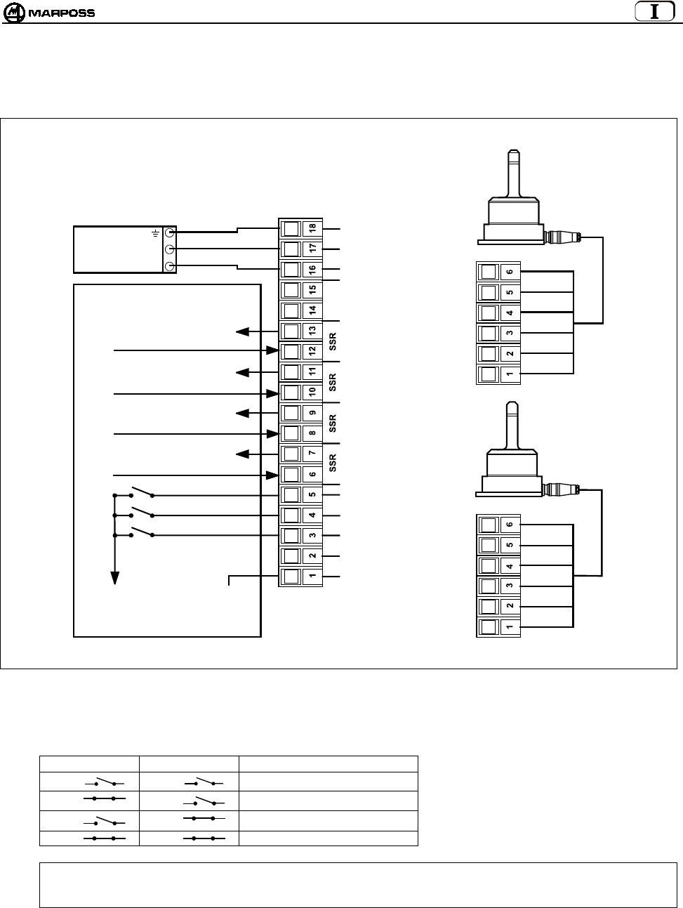
9.4 Collegamenti all’unità di interfaccia
Sulla scheda dell’unità è presente la morsettiera di collegamento; le connessioni vengono effettuate mediante connettori con attacco a
vite.
Figura 9-3. Collegamenti.
9.4.1 Selezione del codice di identificazione
Ingresso proveniente da logica:
SEL 0 SEL 1 CODICE DI IDENTIFICAZIONE
I1 I2 A
I1 I2 B
I1 I2 C
I1 I2 D
Nota: Nel caso si utilizzi un solo trasmettitore NON è necessario gestire questi 2 Ingressi provenienti da CNC. L’interfaccia,
come default, è impostata sul codice di identificazione A, così come lo è il trasmettitore (vedi paragrafo 10.2
“Programmazione del Trasmettitore” a pag. 31).
ANTENNA 1
ANTENNA 2
VERDE
BLU
BIANCO
VIOLA
SCHERMO
ROSSO
VERDE
BLU
BIANCO
VIOLA
SCHERMO
ROSSO
COM
A
UX IN
SEL 0
SEL 1
START/STOP
STATO SONDA 1
SKIP
STATO SONDA 2
SKIP
BATTERIA
SCARICA
ERRORE
A
UX OUT
+24V DC
0V
TERRA
CNC CONTROLLO MACCHINA
0V SOURCE
24V SINK
STATO SONDA 1/ SKIP
STATO SONDA 2/ SKIP
BATTERIA SCARICA
ERRORE
24V
0V
UNITA’ DI
ALIMENT.
I1
I2
24V SOURCE
0V SINK
(
H1
)
(
H2
)
(
I
)
ITALIANO
E86N- Sistema touch con trasmissione radio
26
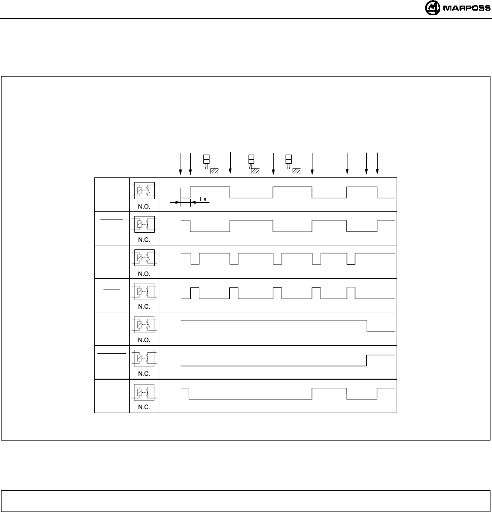
9.5 Diagramma I/O unità di interfaccia E86N
Figura 9-4. Diagramma I/O unità d’Interfaccia.
NOTA: in alcuni ambienti di lavoro particolarmente disturbati da interferenze elettromagnetiche il tempo necessario per attivare la
trasmissione può essere superiore ad 1 secondo (max 6).
Aperto
Chiuso
A
perto
Chiuso
A
perto
Chiuso
A
perto
Chiuso
A
perto
Chiuso
A
perto
Chiuso
A
perto
Chiuso
Stato
Sonda
Stato
Sonda
Skip
Skip
Batteria
scarica
Batteria
scarica
Errore
Segnali
E86N
relè
stato
solido
Start
Sonda attivata
A
riposo
A
pertura contatto
Deflessa
Chiusura contatto
A
riposo
Errore
Errore eliminato
Batteria scarica
Sonda disattivata
mida 27
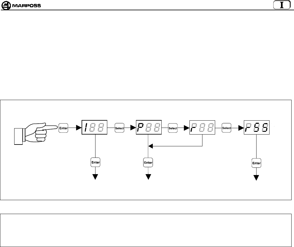
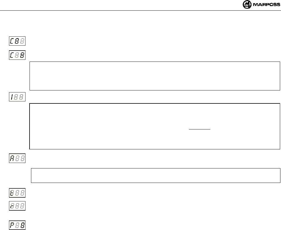
10. PROGRAMMAZIONE DEL SISTEMA
Tenendo premuto per più di 2 secondi il tasto “Enter”, il sistema entra in modalità programmazione. A questo punto occorre scegliere il
tipo di programmazione mediante il tasto “Select”:
I --> Programmazione dell'Interfaccia
P --> Programmazione del Trasmettitore
r --> Programmazione del Trasmettitore in modalità "Recovery"
rSS ÆProgrammazione della funzione “Sniffer”
Effettuata la scelta, attraverso i tasti “Select” ed “Enter” si modificano i dati di programmazione. Il tasto “Select” incrementa il dato di
programmazione corrente mentre il tasto “Enter” lo conferma e passa a quello successivo.
ATTENZIONE: In caso si voglia riprogrammare il solo Canale di funzionamento, si deve Iniziare la procedura partendo dalla
programmazione del Trasmettitore.
In questo modo, visto che l’Interfaccia viene fornita con la funzione Programmazione automatica del canale abilitata
(AP=1 - vedi paragrafo 10.1 “Programmazione dell'interfaccia”), al termine della riprogrammazione del canale di
funzionamento sul trasmettitore, anche l’Interfaccia risulta automaticamente programmata sullo stesso canale.
PROGRAMMAZIONE
DEL TRASMETTITOR
E
PROGRAMMAZIONE
DELL’INTERFACCIA
PROGRAMMAZIONE DEL
TRASMETTITORE IN
MODALITA’ RECOVERY
> 2 secondi
PROGRAMMAZIONE DELLA
FUNZIONE “SNIFFER”
ITALIANO
E86N- Sistema touch con trasmissione radio
28
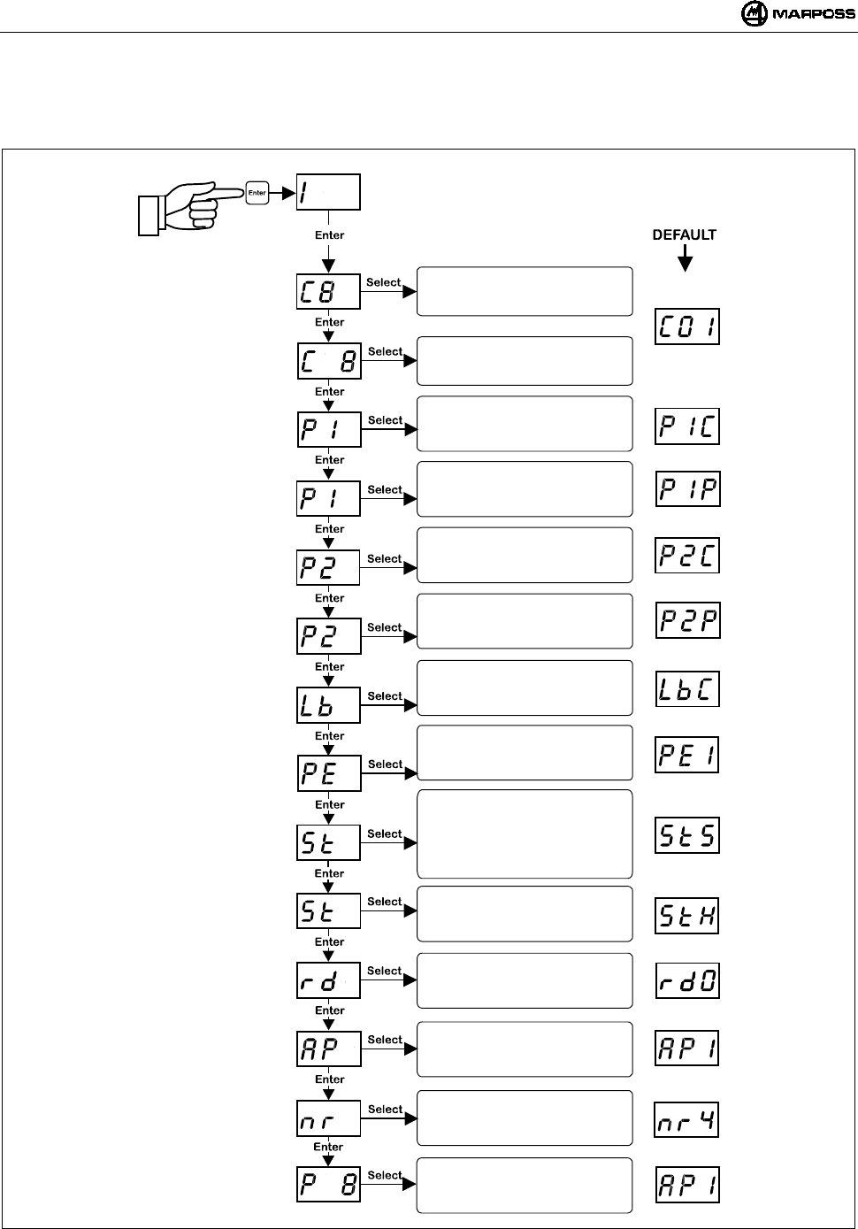
10.1 Programmazione dell'interfaccia
Entrando in modalità di programmazione e selezionando il tipo di programmazione "I", attraverso i tasti “Select” ed “Enter”, si possono
modificare uno ad uno i seguenti valori:
Nota: dopo la conferma dell'ultimo dato si esce dalla programmazione.
Si può però uscire in qualunque momento, tenendo premuto per più di 2 secondi il tasto <ENTER>, annullando la sequenza
corrente.
Inserimento dei canali:
DECINE
Inserimento dei canali:
UNITA’
Polarità uscita probe 1:
P1C= USCITA N.C.
P1O= USCITA N.O.
Funzionalità uscita probe 1:
P1P= PROBE STATUS
P1S= SKIP
Modalità uscita LOW BAT:
LbC= N.C.
LbO= N.O.
Uscita PROBE in errore:
PE0= Probe a 0 (riposo)
PE1= Probe a 1(deflesso)
Segnale START:
S= Standard
P= Pulse
r= rettirgger
Display remoto su staz.base:
0= disabilitato
1= abilitato
Ingresso START:
L= bassa corrente 15V-0,5mA
H= corrente normale 24V-4mA
Progr. automatica canale:
0= disabilitata
1= abilitata
Conferma programmazione:
0= non confermata
1= confermata
Polarità uscita probe 2:
P2C= USCITA N.C.
P2O= USCITA N.O.
Funzionalità uscita probe 2:
P2P= PROBE STATUS
P2S= SKIP
> 2 secondi
Numero tentativi di
attivazione/disattivazione
mida 29
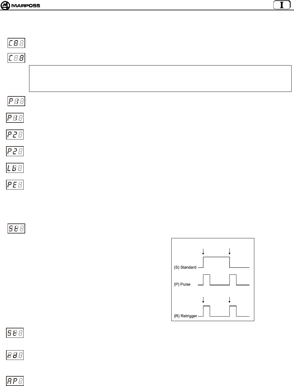
Di seguito, la descrizione dettagliata dei dati di programmazione dell’Interfaccia:
Canale di trasmissione dell’interfaccia – decine: lampeggia il campo decine, che viene incrementato ciclicamente dal
pulsante “Select”.
Canale di trasmissione dell’interfaccia – unità: lampeggia il campo unità, che viene incrementato ciclicamente dal
pulsante “Select”.
ATTENZIONE:
A conferma della programmazione (P1) avvenuta, l’errata selezione dei canali 65-69 o 00 viene considerata non valida
e il display dell’interfaccia lampeggia sul canale errato appena impostato. Per uscire da questa condizione, e sufficiente
rientrare in modalità di programmazione dell’interfaccia e impostare il canale corretto (da 1 a 64).
Polarità dell’uscita PROBE1: i primi digit riportano la scritta “P1”. Il terzo assume ciclicamente i valori <C> ed <O> ad
indicare NORMALE CHIUSO e NORMALE APERTO.
Funzionalità dell’uscita PROBE1: i primi digit riportano la scritta “P1”. Il terzo assume ciclicamente i valori ‘P’ ed ‘S’ ad
indicare uscita normale o tipo “skip” (impulso della durata di 44ms ad ogni variazione di stato del touch).
Polarità dell’uscita PROBE2: i primi digit riportano la scritta “P2”. Il terzo assume ciclicamente i valori <C> ed <O> ad
indicare NORMALE CHIUSO e NORMALE APERTO.
Funzionalità dell’uscita PROBE2: i primi digit riportano la scritta “P2”. Il terzo assume ciclicamente i valori <P> ed <S>
ad indicare uscita normale o tipo “skip” (impulso della durata di 44ms ad ogni variazione di stato del touch)
Polarità dell’uscita LOW_BAT: i primi digit riportano la scritta “lb” Il terzo assume ciclicamente i valori <C> ed <O> ad
indicare normale chiuso e normale aperto.
Uscita Probe in errore: permette di programmare lo stato che assumono le uscite PROBE1 e PROBE2 in condizioni di
errore:
- trasmettitore non attivato
- trasmettitore fuori campo
- batteria completamente scarica
I primi digit riportano la scritta “PE”. Il terzo assume ciclicamente i valori <0> (probe a riposo) ed <1> (probe deflesso).
Modalità di funzionamento segnale Start: i primi digit riportano la scritta “St”.
Il terzo assume ciclicamente i valori ‘S’ (standard), ‘P’ (Pulse) ed ‘r’ (retrigger).
Nella modalità “standard” il fronte di
salita attiva la sonda ed il fronte di
discesa la disattiva.
Nella modalità “pulse” il fronte di salita fa
cambiare di stato la sonda, se è disattiva
si attiva e se è attiva si disattiva.
Infine nella modalità “retrigger” è esclusa
la possibilità di disattivare la sonda via
radio, ed un fronte di salita sul segnale
Start quando la sonda è ancora attiva,
causa il retrigger del timer del
trasmettitore. In questa modalità lo
spegnimento del trasmettitore può solo
avvenire tramite il timer.
Corrente dell’ingresso Start: i primi digit riportano la scritta “St”. Il terzo assume ciclicamente i valori ‘L’ (Low current)
ed ‘H’ (High current). Nella modalità “low current” l’ingresso assorbe circa 0.5mA a 15V (* Nota) Nella modalità “high
current ” l’ingresso è standard ed assorbe circa 4mA a 24V.
Display remoto Antenna: i primi digit indicano la scritta “rd”. Il terzo assume ciclicamente i valori <0> (disabilitato, i led
della stazione base indicano il livello del segnale radio) ed <1> (abilitato, i led della stazione base riportano le
indicazione dei led sull’interfaccia, ad eccezione del led verde centrale della stazione base che è sempre spento) (vedi
8.2 “Modalità display remoto” a pag. 21.
Programmazione automatica del canale dell’interfaccia: i primi digit indicano la scritta “AP”. Il terzo assume
ciclicamente i valori <0> (disabilitata, la programmazione del canale del trasmettitore non ha alcun effetto sul valore
programmato dell’interfaccia) e <1> (abilitata, al termine della programmazione del trasmettitore il canale dell’interfaccia
viene allineato al canale che si sta programmando sul trasmettitore (vedi paragrafo 10.2 Programmazione del
Trasmettitore a pag. 31).
(*) Nota: Questa funzione viene abilitata utilizzando la prolunga cod.6739696319.
Attivazione
Attivazione
Disattivazione
Retrigger
ITALIANO
E86N- Sistema touch con trasmissione radio
30
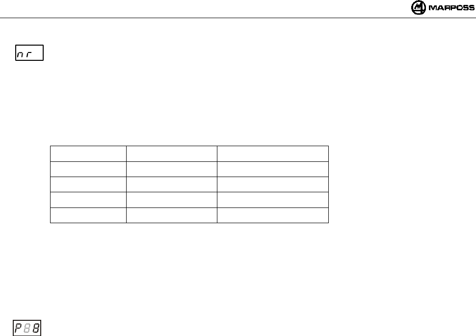
Numero di tentativi attivazione/disattivazione : I primi 2 digit indicano la scritta “nr”.
Il terzo assume ciclicamente i valori da 2 a 9 (valore di default 4).
Questo dato consente di programmare il numero di tentativi massimi che la stazione base esegue per
l’attivazione/disattivazione del trasmettitore. Al raggiungimento di tali tentativi, nel caso il trasmettitore non sia stato
attivato/disattivato, è necessario fornire all’interfaccia un nuovo comando mediante il segnale di start.
L’aumento di numero di tentativi comporta un maggior ritardo nel tempo di attivazione/disattivazione.
Per il valore di default (nr=4) i tempi di attivazione/disattivazione sono come da tabella:
TIPICO VALORE MAX CODICE IDENTIFICAZIONE
1,050 sec 4,200 sec A
1,200 sec 4,800 sec B
1,350 sec 5,400 sec C
1,500 sec 6,000 sec D
Al variare del numero di tentativi i valori in tabella si modificano secondo la relazione:
delay = default delay x (nr / 4)
Come riportato in tabella, il tempo di attivazione/disattivazione dipende anche dal codice di identificazione utilizzato
(sottocanale).
Maggiore è la distanza tra i codici, minore sarà la probabilità di fallimento di attivazione/disattivazione, in situazioni di
alta densità di applicazioni vicine.
Conferma dei dati programmati: Il primo digit riporta il carattere “P”. Il terzo assume ciclicamente i valori <0> per non
programmare l’Interfaccia e <1> per programmarla.
mida 31
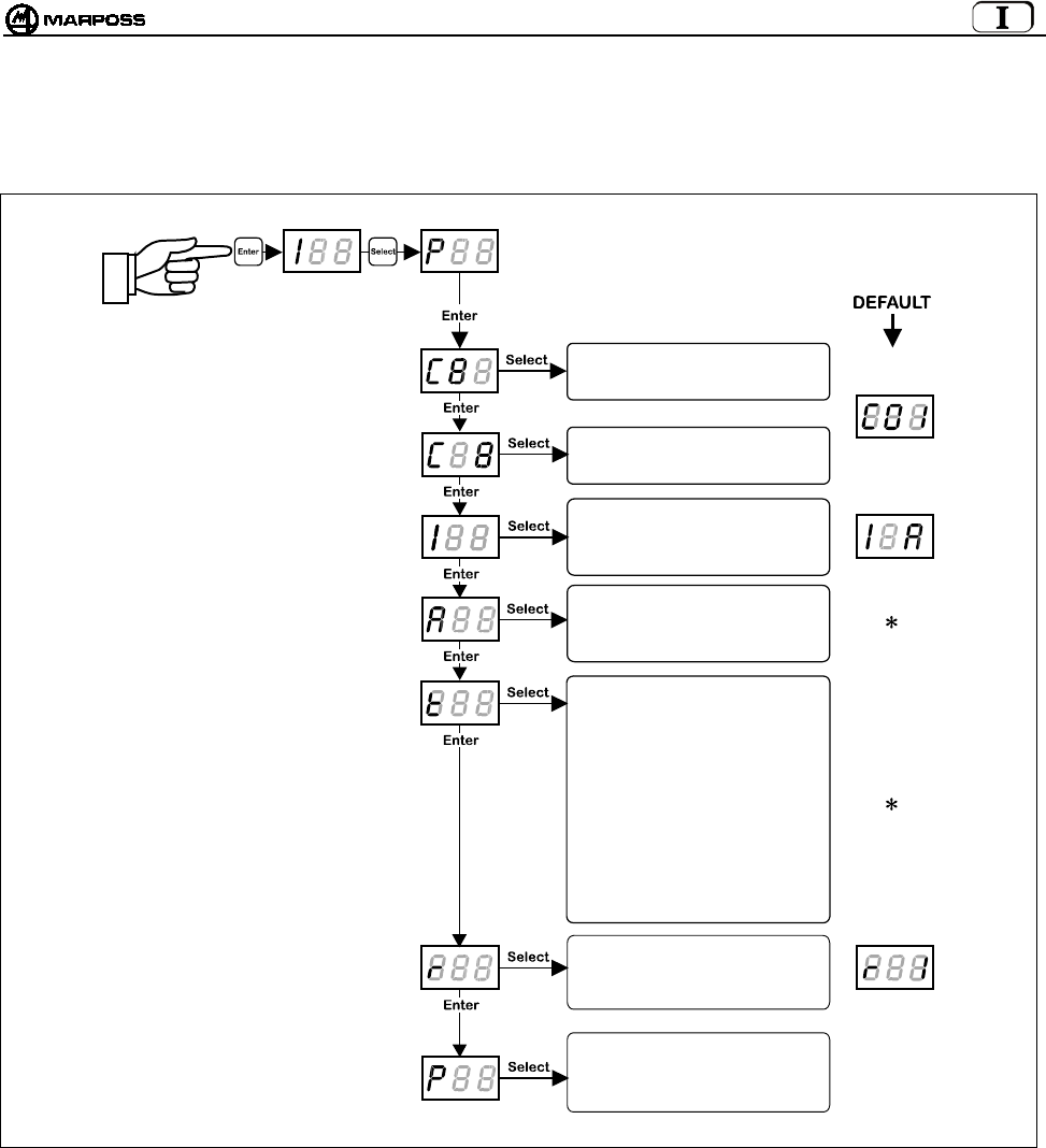
10.2 Programmazione del Trasmettitore
Entrando in modalità di programmazione e selezionando il tipo di programmazione "P", attraverso i tasti “Select” ed “Enter”, si possono
modificare uno ad uno i seguenti valori:
Nota: dopo la conferma dell'ultimo dato si esce dalla programmazione e il trasmettitore viene disattivato.
Si può però uscire in qualunque momento, tenendo premuto per più di 2 secondi il tasto <ENTER>, annullando la
sequenza corrente.
(
∗
) Nota: dipende dal tipo di trasmettitore:
- nel caso di trasmettitore con attivazione radio, il parametro modalità di attivazione sarà impostato su attivazione radio e
il tempo di spegnimento sul valore <5> che corrisponde a 2'14".
- nel caso di attivazione meccanica, il parametro modalità di attivazione sarà impostato su attivazione meccanica e il
tempo di spegnimento sul valore <8> che corrisponde a tempo di spegnimento infinito.
Inserimento dei canali:
DECINE
Inserimento dei canali:
UNITA’
Codice identificazione:
(A, B, C, D)
Modalità attivazione:
0= Radio
1= Meccanica
Tempo di funzionamento:
0= 4"
1= 8"
2= 17"
3= 34"
4= 1'7"
5= 2'14"
6= 4'28"
7= 8'57"
8=
∞
Rettrigger del Timer:
0= Disabilitato
1= Abilitato
Conferma programmazione:
0= non conferma
1= conferma
> 2 secondi
ITALIANO
E86N- Sistema touch con trasmissione radio
32
Di seguito, la descrizione dettagliata dei dati di programmazione del Trasmettitore:
Canale di trasmissione – decine:
lampeggia il campo decine, che viene incrementato ciclicamente dal valore <0> al valore <6>.
Canale di trasmissione – unità: lampeggia il campo unità, che viene incrementato ciclicamente dal valore <0> al
valore <9>.
ATTENZIONE:
A conferma della programmazione (P1) avvenuta, l’errata selezione dei canali 65-69 o 00 viene considerata non valida,
sul display dell’interfaccia lampeggia il canale su cui è impostata l’interfaccia stessa e il trasmettitore può essere
ripristinato solo in modalità “recovery” (vedi 10.3 “Programmazione del trasmettitore in modalità Recovery” a pag. 33).
Codice di identificazione: il primo digit riporta il carattere “I” Il terzo è selezionabile tra i valori <A, B, C, D>.
ATTENZIONE:
Un Trasmettitore è completamente identificato dal numero di canale di lavoro e dal codice di identificazione (es. 12B).
Dato che il codice di identificazione è programmabile per il Trasmettitore ma è un’ingresso da logica esterna (CNC) per
l’Interfaccia, si consiglia di modificare questo parametro sul Trasmettitore solamente se si è sicuri che sia uguale a
quello dell’Interfaccia; in caso contrario il sistema non funzionerà per mancanza di comunicazione e l’unico modo per
ripristinarlo sarà quello di fare una procedura di programmazione del trasmettitore in modalità “Recovery” (vedi
paragrafo 10.3 “Programmazione del trasmettitore in modalità Recovery” a pag. 33).
Modalità di attivazione: il primo digit riporta il carattere “A” Il terzo assume ciclicamente i valori <0> per attivazione
radio e <1> per attivazione meccanica;
ATTENZIONE:
lasciare il valore di default riportato nella pagina precedente.
Tempo di funzionamento: il primo digit riporta il carattere “t”. Il terzo va impostato con un valore compreso tra <0 e 8>,
corrispondente ad un tempo di funzionamento che va da un minimo di 4” (valore 0) ad infinito (valore 8).
Retrigger del timer: il primo digit riporta il carattere “r”. Il terzo assume ciclicamente i valori <0> per retrigger disabilitato
e <1> per retrigger abilitato.
Questo dato, consente l’azzeramento del timer dopo ogni variazione di stato della sonda.
Conferma dei dati programmati. Il primo digit riporta il carattere “P”. Il terzo assume ciclicamente i valori <0> per non
programmare il Trasmettitore e <1> per programmarlo.
mida 33
10.3 Programmazione del trasmettitore in modalità Recovery
Nel caso in cui per il Trasmettitore ci si trovi in una delle seguenti condizioni:
a. canale di trasmissione del trasmettitore sconosciuto
b. programmazione errata del canale di trasmissione (es. 65-69 o 00)
c. programmazione errata del codice di identificazione (diverso da quello dell’Interfaccia)
è prevista una procedura di programmazione del Trasmettitore chiamata “recovery”, che consente di risalire ed eventualmente
modificare i parametri del Trasmettitore.
La procedura si effettua nel seguente modo:
1. lasciando alimentata l’Interfaccia, togliere l’alimentazione al Trasmettitore (svitare il coperchio delle batterie nel caso di
trasmettitore con attivazione radio o aprire il microinterruttore sul cono nel caso di trasmettitore con attivazione meccanica);
2. dall'Interfaccia entrare in modalità di programmazione e selezionare il tipo di programmazione "r";
3. premendo il tasto <ENTER>sul display si visualizza il messaggio "REC";
4. Deflettere il braccetto e mantenerlo tale mentre si fornisce alimentazione al trasmettitore (chiudere il coperchio delle batterie
nel caso di trasmettitore con attivazione radio o chiudere il microinterruttore sul cono nel caso di trasmettitore con attivazione
meccanica);
5. il trasmettitore viene attivato su un canale di servizio anziché sul canale programmato e sul dispaly dell'interfaccia scompare il
messaggio “REC” e si visualizza il numero del canale (con decine lampeggianti) su cui era programmato il trasmettitore;
6. rilasciare il braccetto mantenendo alimentato il Trasmettitore (coperchio chiuso/microinterruttore sul cono chiuso)
A questo punto, ottenuta l’informazione desiderata, si può
• uscire dalla programmazione
tenendo premuto per più di 2 secondi il tasto <ENTER> o semplicemente rilasciando il coperchio/microinterruttore.
• effettuare una normale programmazione del trasmettitore come descritto nel paragrafo 10.2 “Programmazione del
Trasmettitore” a pag. 31.
ATTENZIONE: Se nell’Interfaccia è abilitata la “programmazione automatica del canale” (AP=1 - vedi paragrafo 10.1
“Programmazione dell'interfaccia”), al termine della programmazione del trasmettitore, anche il canale
dell’Interfaccia cambia, allineandosi a quello presente sul Trasmettitore stesso.
> 2 secondi
PROGRAMMAZIONE
DEL TRASMETTITORE
(
vedi
p
ara
g
rafo 10.2
)

ITALIANO
E86N- Sistema touch con trasmissione radio
34
10.4 Analisi occupazione dello spettro elettromgnetico (Funzione “Sniffer”)
L’analisi dell’ occupazione dello spettro elettromagnetico si svolge in due fasi
• Scansione
L’interfaccia E86N esegue ciclicamente la scansione di tutti i 64 canali, memorizzando per ogni canale l’ampiezza massima del
segnale ricevuto;
• Visualizzazione dei risultati
L’interfaccia E86N visualizza i canali e l’ampiezza massima memorizzata durante la scansione precedente.
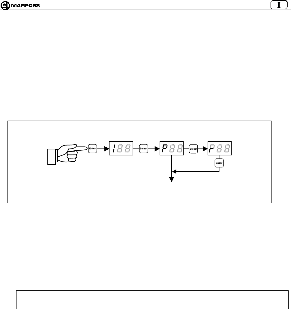
Per attivare la funzione occorre mettere l’interfaccia in “Modo Programmazione” (premendo “Enter” per più di 2 secondi), premere
più volte il tasto “Select” finché sul display non appare la scritta “rSS” e questo punto premere “Enter”.
XX XX XX XX
> 2 secondi
> 2 secondi > 2 secondi > 2 secondi > 2 second
i
Enter=Lista ▲
Select= Lista ▼’
Enter=Lista ▲
Select= Lista ▼
Enter=Lista ▲
Select= Lista ▼
mida 35
10.4.1 Scansione
Premere “Select” finchè sul display appare “St” (Start).
Premendo “Enter” si attiva la scansione che continua finchè non viene nuovamente premuto il tasto “Enter” per più di 2 secondi.
La scansione può essere lasciata attiva anche per lunghi periodi.
Durante la scansione il tasto “Select” non è attivo.
Sul display appaiono in sequenza:
• il numero del canale acquisito “Cnn” (nn= numero del canale 01-64, oltre al canale di attivazione “CA”)
• la corrispondente l’ampiezza del segnale “XX”.
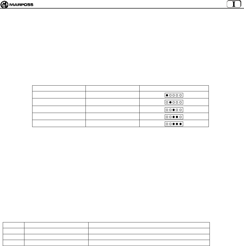
L’ampiezza del segnale è espressa in scala logaritmica e può variare da –9 a 99 (vedi tabella sottostante).
LIVELLO SEGNALE VALORE VISUALIZZATO LED STAZIONE BASE
sotto soglia ≤ -1
molto basso (1) 0 / 3
basso 4 / 7
medio 8 / 11
alto ≥ 12
NOTE:
1. Il valore <0> corrisponde al minimo livello di segnale considerato “comprensibile” (Ampiezza –102dBm e rapporto
Segnale/Rumore > -12dB).
2. Quando è attiva la funzione di scansione sono disabilitate tutte le altre funzioni. (lo stato delle uscite dell’E86N è come in
condizione di errore).
3. I valori massimi acquisiti vengono memorizzati in una memoria non retentiva e pertanto vengono persi allo spegnimento.
4. Quando viene attivata una scansione i precedenti valori massimi acquisiti vengono cancellati.
5. Il tempo di scansione è di circa 1 secondo per canale e quindi una scansione completa richiede circa 70 secondi. Poiché il
sistema è in grado di acquisire un solo canale alla volta, la probabilità di individuare segnali elettromagnetici di breve durata
aumenta allungando il periodo di osservazione.
6. I valori acquisiti sono resi disponibili solo dopo che è stata eseguita almeno una scansione completa.
7. Se le stazioni base sono due viene utilizzato il maggiore dei due dati acquisiti.
10.4.2 Visualizzazione dei risultati
I risultati di una scansione possono essere visualizzati con tre diversi tipi di ordinamento:
Simbolo Ordinamento Primo elemento della lista
HI Segnale ricevuto decrescente Canale su cui è stato ricevuto il segnale di ampiezza massima
LO Segnale ricevuto crescente Canale su cui è stato ricevuto il segnale di ampiezza minima
CH Numero canale crescente Canale 00
Per visualizzare i risultati premere “Select” finché sul display non appare il simbolo corrispondente all’ordinamento desiderato e poi
premere il tasto “Enter”.
Sul display viene visualizzato prima il numero del canale e poi il valore del segnale.
• Premendo il tasto “Enter” si passa all’elemento successivo della lista fino ad arrivare all’ultimo elemento.
• Premendo il tasto “Select” si torna all’elemento precedente, fino ad arrivare al primo elemento.
• Premendo il tasto “Enter” per più di 2 secondi si esce dalla scansione della lista.
Rosso
Giallo
Verde
Verd
i
Verd
i
ITALIANO
E86N- Sistema touch con trasmissione radio
36
11. MONTAGGIO SONDA – TRASMETTITORE STANDARD
11.1 Montaggio sonda – trasmettitore standard
Per il montaggio o lo smontaggio della sonda dal trasmettitore procedere nel seguente modo:
Avvertenza:
In fase di montaggio della sonda è bene assicurarsi che gli anelli di tenuta siano in ottime condizioni e posizionati
correttamente nella loro sede.
SONDA T25/TL25/TT25
- avvitare la flangia (A) al trasmettitore, mediante la chiave apposita (A1).
- avvitare la sonda, alla flangia (A) utilizzando la chiave in dotazione (A2).
SONDA T36
- fissare la sonda alla flangia (B) tramite le viti (B1);
- Avvitare la flangia (B) al trasmettitore utilizzando la chiave in dotazione
SONDA T60/TT60
- fissare la sonda alla flangia (C) tramite le viti (C1);
- Avvitare la flangia (C) al trasmettitore utilizzando la chiave in dotazione;
Avvertenza:
Ad operazione ultimata occorre eseguire l’allineamento del sistema.
Figura 11-1
A
2
A
T25/TL25/TT25
B1 B
T36
C1 C
T60-TT60
A
1

mida 37
11.2 Inserimento prolunghe per sonde (optional)
La prolunga viene inserita tra sonda e trasmettitore per aumentare la profondità di misura del sistema. Per l'inserimento delle prolunghe
procedere nel seguente modo.
Avvertenza:
In fase di inserimento prolunga è bene assicurarsi che gli anelli di tenuta siano in ottime condizioni e posizionati
correttamente nella loro sede.
• Prolunga per sonda T25/TL25/TT25
- Rimuovere la sonda dal trasmettitore con l'apposita chiave (A1) in dotazione.
- Interporre tra sonda e trasmettitore la prolunga (A2) con relativi anelli di tenuta.
- Serrare il gruppo con l'ausilio della chiave (A1) in dotazione.
Figura 11-2
• Prolunga per sonda T36
- Svitare la flangia (B) dal trasmettitore.
- Rimuovere la sonda dalla flangia (B) togliendo le viti (B1).
- Fissare la prolunga (B2) alla flangia (B) tramite le viti (B1).
- Avvitare il gruppo flangia/prolunga, al trasmettitore con la chiave in dotazione
- Fissare la sonda alla prolunga tramite le viti (B3).
• Prolunga per sonda T60/TT60
- Svitare la flangia (C) dal trasmettitore.
- Rimuovere la sonda dalla flangia (C) togliendo le viti (C1).
- Fissare la prolunga (C2) alla flangia (C) tramite le viti (C1).
- Avvitare il gruppo flangia/prolunga, al trasmettitore con la chiave in dotazione
- Fissare la sonda alla prolunga tramite le viti (C3).
Figura 11-3
A
2
A
T25/TL25/TT25
C3
B1
T36
T60/TT60
B
B3
B2
C1
C
C2

ITALIANO
E86N- Sistema touch con trasmissione radio
38
12. MONTAGGIO DEL TRASMETTITORE
12.1 Montaggio del trasmettitore Standard sul cono
- Rimuovere i coperchi batteria (C) del trasmettitore - viti (D) - per accedere ai quattro fori (E) sulla flangia. Il fissaggio con flangia
standard può essere eseguito in due diversi modi:
- Praticare sul cono quattro fori filettati M4x8 (A) e una svasatura centrale (B) come indicato in Figura 12-1.
- inserire fra trasmettitore e cono la sfera (G) ø6 mm in dotazione.
- Fissare il trasmettitore al cono mediante le quattro viti (F).
Allineamento del sistema
- Montare il braccetto sonda (vedere "Montaggio del braccetto sonda").
- Allineare il centro della sfera del braccetto all'asse del cono agendo sulle quattro viti (F).
- Allineato il sistema, serrare le quattro viti (F) con sequenza a croce.
Figura 12-1
D
C
D
C
F
E
F
34
(1,34”)
34
(1,34”)
4,5
±
0,1 mm
(0,177 ± 0,004)

mida 39
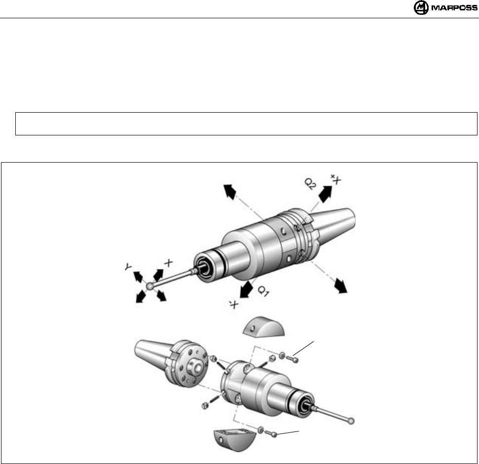
12.2 Montaggio trasmettitore Standard sul cono con flangia di regolazione
1. Rimuovere i coperchi batteria del trasmettitore togliendo le viti (vedere cap.12.1).
Nota: Le operazioni descritte ai punti 2 - 3 - 4 e 5 sono valide solo con trasmettitore con attivazione radio. Il trasmettitore
con attivazione meccanica (microinterruttore sul cono) viene fornito, comprensivo di cono portautensili, con flange
di regolazione già montate. In questo caso proseguire dal punto 6.
2. Rimuovere la flangia standard (C) del trasmettitore togliendo le quattro viti (D).
3. Fissare al trasmettitore la flangia di regolazione (E) mediante le quattro viti (D).
Figura 12-2
4- Praticare sul cono portautensili due fori filettati M4x8 (F).
5- Fissare al cono portautensili la flangia di regolazione (G) mediante le due viti (H).
Nota: Per facilitare l'orientamento del LED (L) del trasmettitore verso l'operatore, sono disponibili tre coppie di fori di
fissaggio che permettono di scegliere la posizione angolare più idonea.
6- Unire i due gruppi (trasmettitore-cono) facendo combaciare i quattro fori filettati (M) della flangia cono (G) con le quattro asole (N)
della flangia trasmettitore (E).
7- Inserire i quattro prigionieri filettati (P) nelle asole (N) e avvitarli nei fori filettati (M) della flangia cono mediante la chiave esagonale
in dotazione.
8- Avvitare i quattro dadi speciali (Q) sui prigionieri.
Figura 12-3
C
D
D
E
P
QL
MG
N
E
F
G
H
H
F=M4x8
ITALIANO
E86N- Sistema touch con trasmissione radio
40
Allineamento del sistema
9. Montare il braccetto sonda (vedi "Montaggio del braccetto sonda").
10. Allineare il centro della sfera del braccetto all'asse del cono agendo sui quattro dadi speciali (Q). Massima traslazione ammessa:
1,7 mm nelle quattro direzioni.
Esempio:
Traslazione della sfera braccetto verso "-X" —> allentare (Q1) e avvitare (Q2). Procedere in modo analogo per le altre direzioni.
11. Allineato il sistema procedere al bloccaggio del gruppo di regolazione; inserire e serrare le due viti (R) di bloccaggio.
Figura 12-4
R
R
mida 41
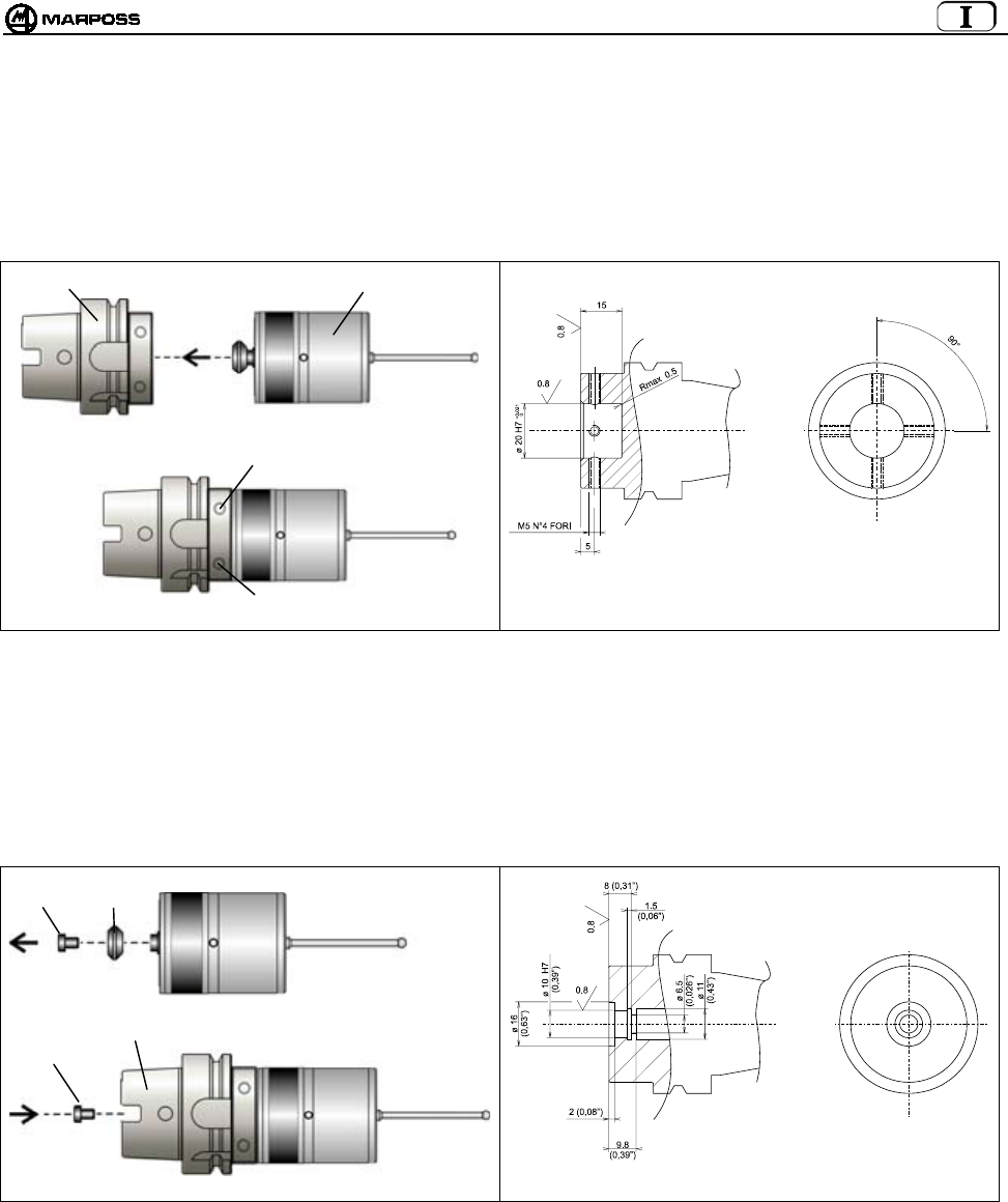
12.3 Montaggio trasmettitore compatto E86N-P sul cono
12.3.1 Fissaggio trasmettitore E86N-P al cono (lavorazione del cono)
• Inserire il cono (A) nel Trasmettitore (B)
• Fissare il Trasmettitore al con mediante 4 grani nei fori (C)
Figura 12-5. Fissaggio del trasmettitore al cono. Figura 12-6. Lavorazione del cono.
12.3.2 Fissaggio al cono del trasmettitore E86N-P senza codolo conico (lavorazione del cono)
• svitare la vite (A) che fissa il codolo conico al trasmettitore (B)
• Inserire il cono (C) nel Trasmettitore (B)
• Fissare il Trasmettitore mediante la vite (A)
Figura 12-7. Fissaggio del trasmettitore al cono Figura 12-8. Lavorazione del cono.
A
B
C
C
A
B
A
C

ITALIANO
E86N- Sistema touch con trasmissione radio
42
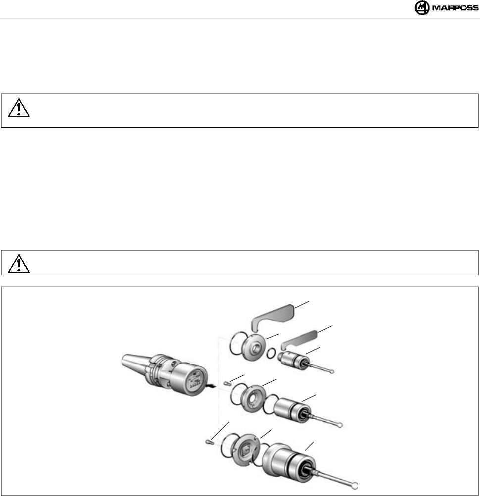
13. MONTAGGIO DEL BRACCETTO
Di seguito viene descritta la procedura di montaggio del braccetto sulla sonda montata su un Trasmettitore Standard, ma dato che il
Trasmettitore Compatto incorpora la sonda e che il portabraccetto è identico, la procedura è la stessa per entrambi i tipi di trasmettitore.
Per il montaggio del braccetto sulla sonda procedere nel seguente modo:
Nota: La procedura descritta di seguito prevede l'impiego della spina di rottura. Tale spina, interposta tra braccetto e
sonda, ha il compito di salvaguardare la sonda in caso di urti accidentali sul braccetto (avviene il distacco del
braccetto della sonda).
Inserire la spina di rottura (A) sulla sonda (B).
Con la chiave (in dotazione) tenere fermo il portabraccetto (C) della sonda e con l'altra chiave, serrare la spina di rottura (A). La
chiave per serrare la spina (A), va inserita nella parte inferiore della spina stessa - posizione (D).
Avvitare il braccetto (F) sulla spina di rottura (A).
Con una chiave tenere ferma la spina e con l'altra, serrare il braccetto.
Inserire il ritegno (E), facendolo scorrere lungo il braccetto stesso fino ad avvolgere la spina di rottura (A). Questo ritegno ha lo
scopo di trattenere il braccetto, in caso di rottura della spina.
Nelle applicazioni via radio si consiglia di utilizzare braccietti in ceramica e non in acciaio, onde evitare eventuali interferenze (poco
probabili). Nel caso non venga utilizzata la spina di rottura avvitare il braccetto direttamente sulla sonda; con una chiave tenere
fermo il portabraccetto (C) e con l'altra serrare il braccetto.
Figura 13-1
A
B
F
A
A
DC
E
mida 43
14. DIAGNOSTICA
14.1 Messaggi di errore
Sul display dell'unità di Interfaccia E86N possono comparire i seguenti messaggi di Errore:
MESSAGGIO
DI ALLARME
CAUSA RIMEDIO
E.E2 Errore di lettura/scrittura Contattare Assistenza tecnica o riprogrammare nuovamente tutti i Dati.
E.nb Nessuna Antenna collegata Verificare collegamento con Antenna.
Errato collegamento dell’antenna Verificare che in caso di una sola Antenna, questa sia collegata sul
morsetto inferiore (H1) dell’Interfaccia.
E.b1 Errore di comunicazione con Antenna 1 Verificare collegamento con Antenna 1.
E.b2 Errore di comunicazione con Antenna 2 Verificare collegamento con Antenna 2.
F.P1 Fault (corto circuito) su uscita PROBE 1 Verificare collegamento su uscita PROBE 1.
F.P2 Fault (corto circuito) su uscita PROBE 2 Verificare collegamento su uscita PROBE 2.
F. Er Fault (corto circuito) su uscita ERROR Verificare collegamento su uscita ERROR.
F. Lb Fault (corto circuito) su uscita LOW_BAT Verificare collegamento su uscita LOW_BAT.
F. Au Fault (corto circuito) su uscita AUX Verificare collegamento su uscita AUX.
Nota: Dopo che sono state rimosse le cause dell'errore, le segnalazioni possono essere rimosse dal display premendo
contemporaneamente i tasti <Select> e <Enter> per più di 2 secondi (ad eccezione dei messaggi E.b1 e E.b2 che si
resettano togliendo e fornendo alimentazione).
ATTENZIONE:
tutte le operzioni di accensione o spegnimento del sistema, devono essere fatte con il/i connettore/i dell’Antenna collegato/i.
14.2 Segnalazione dei Led
I led presenti sul pannello dell'Unità di Interfaccia possono dare le seguenti segnalazioni:
CAUSA RIMEDIO
Assenza di alimentazione Verificare che ai capi dei morsetti 16 e 17 della
morsettiera dell'unità di interfaccia vi sia tensione.
LED "POWER"
SPENTO
Fusibile ripristinabile aperto Attendere alcuni minuti con interfaccia non alimentata.
Trasmettitore- Antenna fuori campo di trasmissione Accertarsi che durante i movimenti della sonda il led
verde ""tuning"" presente sul ricevitore rimanga acceso.
Batteria trasmettitore totalmente scarica o assente Sostituirla
Scaduto tempo di trasmissione Dare un segnale di start per riattivare il sistema.
Mancanza di collegamento elettrico tra antenna e
Interfaccia
Verificare il cavo del ricevitore e le relative connessioni
all'interfaccia.
LED "ERROR"
ACCESO"
Vi è interferenza elettrica o elettromagnetica Allontanare il cavo proveniente dall'antenna da eventuali
cavi di potenza. Cambiare canale di lavoro.
Non c'è collegamento elettrico tra sonda e
trasmettitore.
Verificare il collegamento tra sonda e trasmettitore.
Sonda danneggiata
LED "PROBE":
NON CAMBIA
STATO AL
TOCCO DELLA
SONDA Trasmettitore danneggiato
Smontare la sonda dal trasmettitore, collegare tra loro i
contatti a molla ed interrompere il contatto. se nonostante
ciò il led non cambia stato, il trasmettitore è guasto. Se
cambia stato significa che la sonda è guasta.
Braccetto allentato Controllare che il braccetto e la spina di rottura (se
utilizzata) siano bene avvitati alla sonda.
Flangia allentata Avvitare tutte le viti.
SCARSA
RIPETIBILITA'
Guarnizione interna forata o danneggiata. Sostituire la sonda.

ITALIANO
E86N- Sistema touch con trasmissione radio
44
15. MANUTENZIONE
15.1 manutenzione ordinaria
15.1.1 Pulizia e controlli
Per ottenere sempre le migliori prestazioni dal sistema di misura, è buona norma sottoporlo a regolari operazioni di pulizia e controllo.
Si tratta di operazioni semplici da eseguire periodicamente in funzione delle condizioni di impiego.
- Verifica integrità cablaggio
Verificare periodicamente l'integrità dei cavi ed il serraggio dei morsetti elettrici.
- Controllo tenuta guarnizioni
Anteriormente la sonda è protetta da due guarnizioni sufficienti per un'ottima protezione in normali condizioni di impiego. Controllare
periodicamente che la guarnizione esterna non presenti segni di usura. In tal caso, provvedere alla sostituzione della guarnizione
stessa.
In caso di danneggiamento della guarnizione interna, la sonda dovrà essere inviata al fornitore per la riparazione.
15.1.2 Inserimento/Sostituzione Batteria Trasmettitore
Per l'inserimento della batteria nel trasmettitore o per la sua sostituzione in seguito all'accensione del led "low battery" sul pannello unità
interfaccia (livello batteria sul display uguale a 3) e attivazione del segnale di uscita LOW BATTERY, procedere nel seguente modo:
• TRASMETTITORE STANDARD:
- Svitare le due viti (A) del coperchio (C) contrassegnato dal simbolo grafico della batteria.
- Togliere la batteria scarica, se presente, e innestare la nuova batteria (B) negli appositi contatti del coperchio (C) rispettando la
polarità.
- Riposizionare il coperchio (C) prestando attenzione alla posizione dei contatti elettrici.
- Riavvitare le viti (A) applicando una coppia di serraggio di 2Nm.
• TRASMETTITORE COMPATTO:
- Svitare le tre viti (D) del coperchio (F) e rimuoverlo.
- Rimuovere le batterie scariche, se presenti, e innestare le nuove batterie (E) negli appositi alloggiamenti rispettando la polarità
indicata sul corpo del trasmettitore.
- Riposizionare il coperchio (F) prestando attenzione alla posizione dei contatti elettrici.
- Riavvitare le viti (D) applicando una coppia di serraggio di 2Nm.
Nel paragrafo 7.2 “Durata della batteria” è indicata la durata della batteria in rapporto all'impiego e al tipo.
Figura 15-1. Inserimento/Sostituzione delle batterie
A
B
C
D
F
E
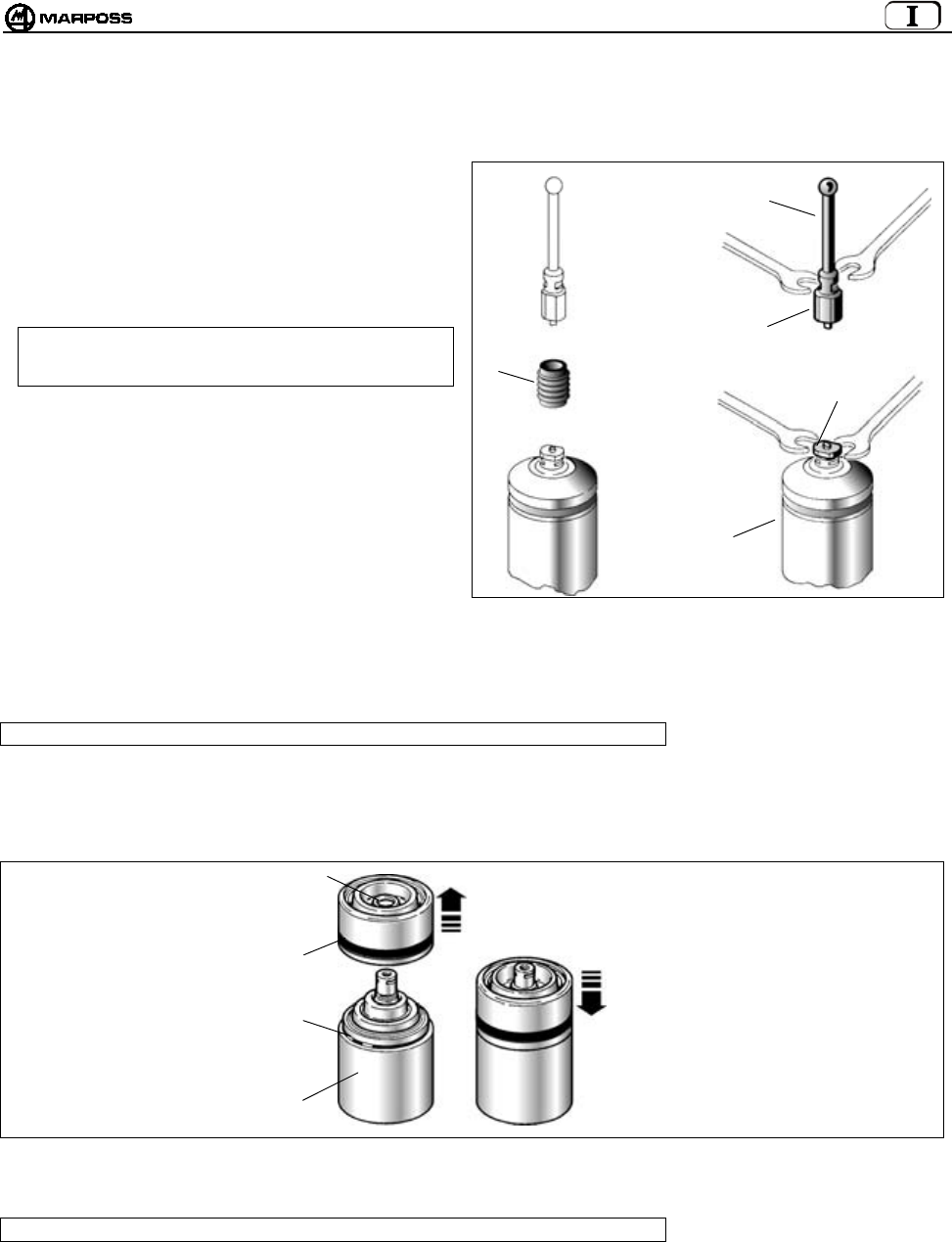
mida 45
15.2 Manutenzione straordinaria
15.2.1 Sostituzione spina di rottura/braccetto
In caso di urti accidentali sul braccetto provvedere come segue
alla sostituzione della spina rotta e/o del braccetto.
1 - Liberare il ritegno (A) sfilandolo dalla spina rotta o piegata.
2 - Liberare il braccetto (B) e la sonda (C) dalla spina rotta (D).
3.- Rimuovere il braccetto danneggiato dalla sonda (C).
Nota: Eseguire queste operazioni tenendo fermo il
portabraccetto della sonda con la chiave in
dotazione.
4 - Procedere quindi al montaggio della nuova spina e del
braccetto (vedere "Montaggio del braccetto sonda").
Figura 15-2
15.2.2 Sostituzione guarnizione esterna
Nota: questa procedura è valida solo per sonde montate su Trasmettirori Standard
1- Togliere il braccetto e l'eventuale spina di rottura.
2- Sfilare dal corpo sonda (A) la protezione anteriore (B) con guarnizione (C).
3- Controllare lo stato dell'anello di tenuta anteriore (D) ed eventualmente sostituirlo.
4- Inserire la nuova protezione anteriore con guarnizione fino a scatto avvenuto.
Figura 15-3
15.2.3 Sostituzione sonda/trasmettitore
Nota: questa procedura è valida solo per sonde montate su Trasmettirori Standard
1- Togliere il braccetto e l'eventuale spina di rottura.
Vedere "Montaggio del braccetto sonda".
2- Procedere alla sostituzione della sonda come indicato in "Montaggio/smontaggio sonda-trasmettitore".
A
D
B
C
D
D
B
C
A

ITALIANO
E86N- Sistema touch con trasmissione radio
46
16. Accessori
16.1 Gruppo supporto aria di pulizia per Trasmettitore Compatto
In gruppo supporto aria di pulizia (A) va fissato sui rispettivi fori (B) presenti sul trasmettitore e sul cono (Figura 16-2). La pressione
dell’aria fornita dev’essere ≤6 bar (88.175psi).
Figura 16-1 Figura 16-2
A
A
B
B

mida 47
17. LISTA RICAMBI
CODICE N° DESCRIZIONE NOTE
1019108005 Spina di rottura lunghezza 15 mm
1019108003 Ritegno braccetto
2915335018 Kit di ricambi per T25/TL25/TT25 COMPRENDE:
protezione frontale completa di guarnizione,
O-ring anteriore e posteriore, ritegno braccetto
2915340010 Kit di ricambi per T36G COMPRENDE:
protezione frontale sonda completa di
guarnizione, O-ring e ritegno braccetto
2915345007 Kit di ricambi per T60G/TT60 COMPRENDE:
protezione frontale sonda completa di
guarnizione, O-ring e ritegno braccetto
2915335013 Protezione frontale per T25/TL25/TT25
2915340006 Protezione frontale per T36
2915345012 Protezione frontale per T60
3415335200 Sonda T25G
3415335201 Sonda T25S
3424306040 Sonda TL25G
3424306041 Sonda TL25S
3415340200 Sonda T36G
3415340201 Sonda T36S
3415345030 Sonda T60G
3415345050 Sonda T60S
3424310000 Sonda TT25
3424310100 Sonda TT25H
3424451000 Sonda TT60
2019923021 Flangia fissaggio trasmettitore per T25/TL25/TT25 Completa di O-ring
2019923022 Flangia fissaggio trasmettitore per T36 Completa di O-ring
2019923023 Flangia fissaggio trasmettitore per T60/TT60 Completa di O-ring
2915335023 Prolunga per T25/TL25/TT25 L=23,5 mm
2915335100 Prolunga per T25/TL25/TT25 L=50 mm
2915335110 Prolunga per T25/TL25/TT25 L=100 mm
2915335120 Prolunga per T25/TL25/TT25 L=150 mm
2915340125 Prolunga per T36 L=50 mm
2915340126 Prolunga per T36 L=100 mm
2915340127 Prolunga per T36 L=150 mm
2915345040 Prolunga per T60/TT60 L=50 mm
2915345050 Prolunga per T60/TT60 L=100 mm
2915345060 Prolunga per T60/TT60 L=150 mm
3019917110 Cono DIN 69871/A 40 con interruttore e flangia di regolazione
3019917120 Cono DIN 69871/A 45 con interruttore e flangia di regolazione
3019917130 Cono DIN 69871/A 50 con interruttore e flangia di regolazione
3019917140 Cono CAT 40 con interruttore e flangia di regolazione
3019917150 Cono CAT 45 con interruttore e flangia di regolazione
3019917160 Cono CAT 50 con interruttore e flangia di regolazione
1502027040 Guarnizione per semiguscio
1502027050 Guarnizione semiguscio (lato contatti)
1502018260 Vite speciale per portapila
4162100005 Pila Alcalina 9V
4162100302 Pila Litio 9V
6180830500 Coperchio portapila senza contatti
2015340100 Kit chiavi COMPRENDE:
chiavi per il braccetto e chiavi a
brugola da 1,5 / 2 / 2,5 / 3 / 4 mm
1320131000 Chiave speciale per T25/TL25/TT25
1320367000 Chiave speciale per flangia T25/TL25/T36/T60/TT25/TT60
2919917110 Flangia di regolazione per trasmettitore Standard
6871982001 Trasmettitore E86N con attivazione radio
TRASMETTITORE STANDARD E86N E SONDE
6871982101 Trasmettitore E86N con attivazione meccanica

ITALIANO
E86N- Sistema touch con trasmissione radio
48
CODICE N° DESCRIZIONE NOTE
1019108005 Spina di rottura lunghezza 15 mm
1019108003 Ritegno braccetto
2015340100 Kit chiavi COMPRENDE:
chiavi per il braccetto e chiavi
a brugola da 1,5 / 2 / 2,5 / 3 / 4 mm
4400000219 Guarnizioni OR 2081 PARKER 2-19 (per coperchio pila)
4306400804 Viti TCCE UNI-5931-12K M4X8 (per coperchio pila)
4162100004 Pila Alcalina 1,5V
6180980085 Gruppo aria di pulizia
TRASMETTITORE COMPATTO E86N-P
6871983000 Trasmettitore E86N-P con attivazione radio
6871980000 Antenna E86N
6180985017 Cavo per collegamento antenna 15m
ANTENNA E
PROLUNGHE
6180985027 Cavo per collegamento antenna 30m
INTERFACCI
A
8304870000 Interfaccia E86N
ACCESSORI
6739696319 Prolunga Collegamento - E86N CNC HEIDENHAIN

mida 49
E86N
TOUCH SYSTEM WITH RADIO TRANSMISSION
Installation and user manual
ENGLISH
E86N- Touch system with radio transmission
50
The product and any part that can be mechanically separated from it must not be
disposed of the environment and must not be disposed of as municipal or general
waste (Law for national adoption of European directives 2002/95/EC and 2002/96/EC
and others).
The provisions of the law only apply to products identified as WEEE (waste electrical and electronic
equipment) marked with the appropriate symbol and in any case put on the market after 13 August 2005.
Once put out of use, the WEEE product may contain substances and parts that are harmful to human
health and the environment and which must be subject to professional treatment for reuse, recycling or
definitive disposal.
Deliver the WEEE product to an authorised WEEE treatment centre, or contact the local organisation
responsible or your nearest Marposs service centre for information.
Illegal disposal of a WEEE product is a crime punishable by penalties.
2002/95/CE
2002/96/CE
MARPOSS S.p.A. is not obliged to notify customers of changes to the product.
The descriptions in this manual in no way authorise tampering by unauthorised personnel.
Any tampering with the equipment will immediately invalidate the warranty.

mida 51
Contents
1. GENERAL REGULATIONS AND DIRECTIONS ................................................................................................................................... 53
2. SYSTEM COMPONENTS ...................................................................................................................................................................... 54
3. CONFIGURATION AND OPERATION .................................................................................................................................................. 55
4. USING THE SYSTEM ............................................................................................................................................................................ 56
5. E86N-P COMPACT TRANSMITTER AND MEASURING PROBE........................................................................................................ 57
6. RADIO TRANSMISSION........................................................................................................................................................................ 58
6.1 Description ..................................................................................................................................................................................... 58
6.1.1 Distances when using more than one system ......................................................................................................................... 58
6.2 Transmission activation ................................................................................................................................................................. 59
6.2.1 Radio activation ....................................................................................................................................................................... 59
6.2.2 Mechanical activation .............................................................................................................................................................. 59
6.3 Transmission deactivation ............................................................................................................................................................. 59
6.3.1 Transmitter with radio activation.............................................................................................................................................. 59
6.3.2 Transmitter with mechanical activation.................................................................................................................................... 59
7. E86N TRANSMITTER ............................................................................................................................................................................ 60
7.1 Description ..................................................................................................................................................................................... 60
7.2 Battery life and indications on the Interface................................................................................................................................... 61
7.3 Dimensions of the transmitter with probes..................................................................................................................................... 62
7.3.1 Standard transmitter with standard flange............................................................................................................................... 62
7.3.2 Standard transmitter with adjusting flange .............................................................................................................................. 63
7.4 Dimensions of the compact transmitter.......................................................................................................................................... 64
7.4.1 E86N-P compact transmitter ................................................................................................................................................... 64
7.4.2 E86N-P compact transmitter without conical shank ................................................................................................................ 64
8. E86N RECEIVER ................................................................................................................................................................................... 65
8.1 Description of the Antenna and extension with connector............................................................................................................. 65
8.2 Remote display mode .................................................................................................................................................................... 65
8.3 Connecting up the antenna............................................................................................................................................................ 65
8.4 Fitting the antenna ......................................................................................................................................................................... 66
9. E86N INTERFACE UNIT........................................................................................................................................................................ 67
Interface unit front panel ......................................................................................................................................................................... 67
9.2 Interface unit dimensions ............................................................................................................................................................... 68
9.3 E86N Interface technical specifications ......................................................................................................................................... 68
9.4 Connections to the interface unit ................................................................................................................................................... 69
9.4.1 Selecting the identification code.............................................................................................................................................. 69
9.5 Diagram of E86N interface unit I/Os .............................................................................................................................................. 70
10. PROGRAMMING THE SYSTEM.......................................................................................................................................................... 71
10.1 Programming the interface............................................................................................................................................................. 72
10.2 Programming the Transmitter ........................................................................................................................................................ 75
10.3 Programming the transmitter in Recovery mode ........................................................................................................................... 77
10.4 Analysis of electromagnetic spectrum occupation (“SNIFFER” function) ...................................................................................... 78
10.4.1 Scan ........................................................................................................................................................................................ 79
10.4.2 Viewing results ........................................................................................................................................................................ 79
11. FITTING THE PROBE – STANDARD TRANSMITTER....................................................................................................................... 80
11.1 Fitting the probe – standard transmitter ......................................................................................................................................... 80
11.2 Inserting probe extensions (optional)............................................................................................................................................. 81
12. FITTING THE TRANSMITTER............................................................................................................................................................. 82
12.1 Fitting the Standard transmitter on the taper ................................................................................................................................. 82
12.2 Fitting the Standard transmitter on the taper with adjusting flange................................................................................................ 83
12.3 Fitting the E86N-P compact transmitter on the taper..................................................................................................................... 85
12.3.1 Fixing the E86N-P transmitter to the taper (working on the taper) .......................................................................................... 85
12.3.2 Fixing the E86N-P transmitter without conical shank to the taper (working on the taper) ....................................................... 85
13. FITTING THE FINGER ......................................................................................................................................................................... 86
14. DIAGNOSTICS..................................................................................................................................................................................... 87
14.1 Error messages.............................................................................................................................................................................. 87
14.2 LED indications .............................................................................................................................................................................. 87
15. MAINTENANCE ................................................................................................................................................................................... 88
15.1 Routine maintenance ..................................................................................................................................................................... 88
15.1.1 Cleaning and checks ............................................................................................................................................................... 88
15.1.2 Inserting/Changing the Transmitter Battery............................................................................................................................. 88

ENGLISH
E86N- Touch system with radio transmission
52
15.2 Extraordinary maintenance ............................................................................................................................................................ 89
15.2.1 Substituting the crash protection pin/finger.............................................................................................................................. 89
15.2.2 Substituting the outer seal ....................................................................................................................................................... 89
15.2.3 Substituting the probe/transmitter............................................................................................................................................ 89
16. ACCESSORIES.................................................................................................................................................................................... 90
16.1 Cleaning air support unit for Compact Transmitter ........................................................................................................................90
17. SPARE PARTS LIST............................................................................................................................................................................ 91
mida 53
1. GENERAL REGULATIONS AND DIRECTIONS
FOREWORD
This instruction manual provides all specific information necessary to familiarise yourself with and correctly use the MARPOSS
equipment in your possession.
The descriptions in this manual are intended for the following personnel:
• MARPOSS or Customer personnel who install the equipment.
• Customer technical personnel who operate directly with the MARPOSS equipment.
• Customer technical personnel responsible for maintaining the production line in which the MARPOSS equipment is installed.
ALL RIGHTS RESERVED. THIS MANUAL IS FOR INTERNAL USE BY THE CUSTOMER ONLY. ANY OTHER USE IS PROHIBITED.
TESTING AND WARRANTY
Defects in the materials are covered by the warranty with the following limitations:
• TERM OF THE WARRANTY: the warranty covers the product and all repairs carried out within the time limits agreed.
• WHAT IS COVERED BY THE WARRANTY: the warranty applies to the product and its parts marked with the serial number or other
identification number used by MARPOSS.
The above-mentioned warranty is valid unless other agreements are reached between MARPOSS and the Customer.
GENERAL SAFETY REGULATIONS
The equipment was built in conformity with IEC EN60950 standards.
CONVENTIONS AND SYMBOLS USED
Several typographical conventions were used to draw up this manual.
Specifically, there are two types of safety warnings:
Warning:
Indicates the possibility of damage to the electronic unit and other devices connected to it, or the possibility of losing data.
Caution:
Indicates a hazard for the operator or technician.
Important information which may help you to understand and use the system appears in a box beside the word "Note" in bold type.

ENGLISH
E86N- Touch system with radio transmission
54
2. SYSTEM COMPONENTS
A1 - E86N probe and transmitter (standard)
A2 - E86N-P transmitter (compact)
B - Crash protection pin (optional)
C - Finger retainer (optional)
D - Finger
E - Antenna
F - E86N interface unit
G - Two open-end wrenches CH 5 - 5.5 and a hexagon wrench kit
H - Special wrench for T25 probe and mechanical extensions
I - Probe extensions (optional)
L - Auxiliary antenna (optional)
Figure 2-1. System components.
A1
B
C
D
E
G
F
H
I
L
A2
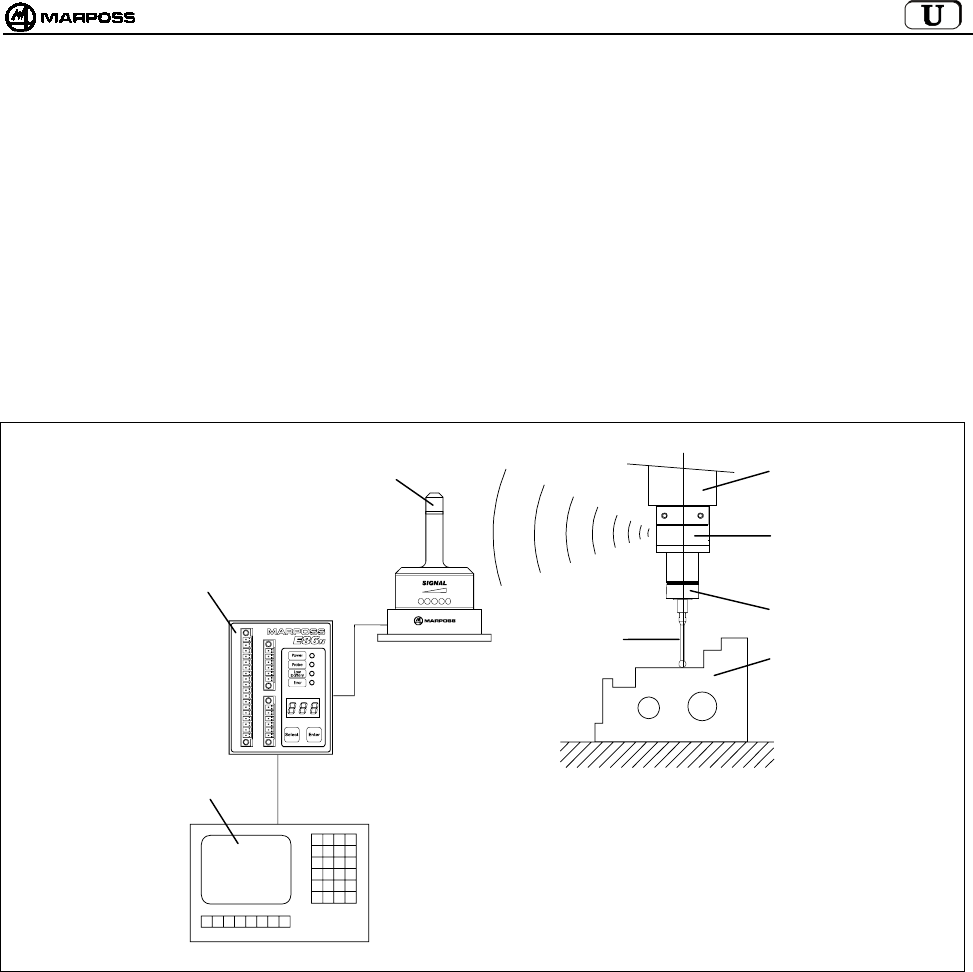
mida 55
3. CONFIGURATION AND OPERATION
The touch system with radio transmission identifies points in space which are processed by the machine tool CNC to provide
measurements. These points are detected by the probe, a precision multi-directional microswitch, and sent by the radio transmission
system, consisting of a transmitter and a receiver, to the interface unit, which adapts them for use by the CNC. The measuring cycle
retrieves the probe/transmitter unit mounted on the tool taper from the tool magazine and inserts it in the spindle. The system is easy to
use and is designed to operate in the most hostile industrial environments. It is used on machining centres and milling machines for:
identifying, positioning and measuring the part to be machined and measuring the part after machining.
System typical application:
A - Part to be measured E - Machine tool spindle
B - Finger F - E86N antenna
C - Touch probe G - E86N interface unit
D - E86N transmitter H - Machine tool CNC
Figure 3-1. Configuration and operation.
BA
C
D
E
F
G
H
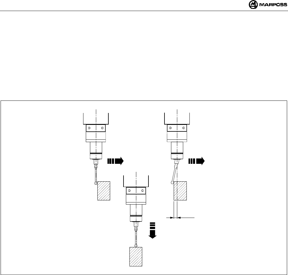
ENGLISH
E86N- Touch system with radio transmission
56
4. USING THE SYSTEM
The measuring system is multi-directional in the x/y/+z hemisphere.
Contact between the finger and the surface of the part to be inspected generates a signal used by the machine tool to save the
point of contact and to stop the machine axes. For good system repeatability, use a constant measuring speed.
The measuring speed selected must allow the machine axis to stop within the overtravel limits for the probe used.
Before using the probe, compensate for the systematic measuring error of the system made up of the probe, the machine tool and
the CNC by performing calibration. The systematic error is characteristic of each measuring direction and repeatable, therefore,
calibration must be carried out in every direction in which the measurement is taken. To calibrate the system, take measurements
at points of the machine with known values (R) and calculate the differences between these and the values measured (R+K1).
Enter this difference (K1) in the CNC tool correction parameters. It is retrieved each time a measurement is taken in the same
direction.
Figure 4-1. Using the system.
X/Y X/Y
Z
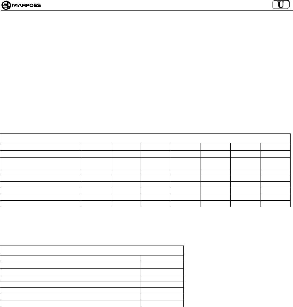
mida 57
5. E86N-P COMPACT TRANSMITTER AND MEASURING PROBE
The measuring probe is a precision multi-directional microswitch used in applications on machines which perform NC shavings removal,
to check and measure tools and parts.
Various models of touch probes multi-directional in the x/y/+z hemisphere are available.
There are two versions of some probe models, with different front protection:
• “Version G” with fabric-finish seal for improved protection against coolant.
• “Version S” with metal shield for protection against shavings.
For an optimum solution to the specific requirements of different machine tools, the following probes are available:
T25G / T25S probe
TL25G / TL25S probe
T36G / T36S probe
T60G / T60S probe
TT25 probe (only with seal)
TT25H probe (only with seal)
TT60 probe (only with seal)
Table 5-1. Probe technical specifications.
Type of probe T25 TL25 T36 T60 TT25 TT25H TT60
Probe axes ±X, ±, Y+Z±X, ±Y, +Z±X, ±Y, +Z±X, ±Y,+Z±X, ±Y,+Z±X, ±Y,+Z±X, ±Y,+Z
Probe unidirectional repeatability (2 σ)
with speed up to 600 mm/min.
0.5 µm0.5 µm0.5 µm1 µm1 µm2 µm1 µm
Measuring force in plane X, Y 200 gf 90 gf 260 gf 280 gf 50-95 gf 90-175 gf 70-120 gf
Measuring force in direction Z 1200 gf 550 gf 1200 gf 1200 gf 580 gf 1080 gf 580 gf
Overtravel in plane X, Y 11.2 mm 11.2 mm 14.4 mm 22 mm 11.6 mm 11.6 mm 19 mm
Overtravel in direction Z4 mm 4 mm 4.2 mm 6.4 mm 4 mm 4 mm 6.4 mm
SPECS. FOR FINGER 35 mm 35 mm 40 mm 50 mm 35 mm 35 mm 50 mm
IEC degree of protection IP67 IP67 IP67 IP67 IP67 IP67 IP67
Unlike the Standard transmitter, on which any of the measuring probes listed in Table 5-1 can be fitted, the E86N-P Compact transmitter
incorporates the probe and its technical specifications are as follows:
Table 5-2. Compact transmitter technical specifications.
Axes ±X, ±, Y+Z
Unidirectional repeatability (2 σ) with speed up to 600 mm/min. 0.5 µm
Measuring force in plane X, Y 200 gf
Measuring force in direction Z1200 gf
Overtravel in plane X, Y 11.2 mm
Overtravel in direction Z4 mm
SPECIFICATIONS FOR FINGER 35 mm
IEC degree of protection IP68

ENGLISH
E86N- Touch system with radio transmission
58
6. RADIO TRANSMISSION
6.1 Description
The radio transmission system consists of three elements:
Transmitter: issues the information required by the CNC to process
the measurement.
Antenna: receives the signal from the transmitter and sends it to the
E86N interface unit.
Interface unit: processes the signals and converts them into a form
which the CNC can use.
The E86N system allows you to programme 64 different transmission
channels using the keyboard on the interface (see sec. 10
"PROGRAMMING THE SYSTEM” on page 71)
Two antennas can be connected to the E86N interface unit, to increase
the range of transmission and reliability of the radio communication.
The system lets you use up to a maximum of 4 transmitters on the same
machine tool (Figure 6-1), operating on the same channel and activated
alternately, one at a time, by a different identification code (see sec. 10.2
“Programming the Transmitter" on page 75).
Figure 6-1. Radio transmission system.
Table 6-1. Technical specifications.
- Transmission distance : 15 m - Activation power : <10 mW
- Transmission power : <1mW - No. of transmission channels : 64
- Activation/deactivation and
programming distance
: 5 m - Transmission frequency :433,075 - 434,775
MHz
Table 6-2. Transmission frequencies.
CHANNEL FREQUENCY CHANNEL FREQUENCY CHANNEL FREQUENCY CHANNEL FREQUENCY
1 433,075 17 433,475 33 434,000 49 434,400
2 433,100 18 433,500 34 434,025 50 434,425
3 433,125 19 433,525 35 434,050 51 434,450
4 433,150 20 433,550 36 434,075 52 434,475
5 433,175 21 433,575 37 434,100 53 434,500
6 433,200 22 433,600 38 434,125 54 434,525
7 433,225 23 433,625 39 434,150 55 434,550
8 433,250 24 433,650 40 434,175 56 434,575
9 433,275 25 433,675 41 434,200 57 434,600
10 433,300 26 433,700 42 434,225 58 434,625
11 433,325 26 433,725 43 434,250 59 434,650
12 433,350 28 433,750 44 434,275 60 434,675
13 433,375 29 433,775 45 434,300 61 434,700
14 433,400 30 433,800 46 434,325 62 434,725
15 433,425 31 433,825 47 434,350 63 434,750
16 433,450 32 433,850 48 434,375 64 434,775
6.1.1 Distances when using more than one system
To avoid interference between systems positioned close to one another,
the following distances must be observed:
At least 2 metres between the Antennas of the systems,
irrespective of whether or not adjacent channels are used (e.g.:
CH5 and CH6).
At least 0.2 metres between the transmitters of the systems,
irrespective of whether or not adjacent channels are used.
At least 0.5 metres between the transmitter of one system and the
Antenna of the other system operating on adjacent channels.
NOTE: when using 2 systems on the same machine (e.g.: twin
spindle machining centres), as well as observing the
distances indicated in Figure 6-2, you must also use two
NON-adjacent channels and identification codes “A” and
“D”.
Systems operating on the same channel must be at least 100
metres apart.
Figure 6-2. Distances when using more than one system.
ABCD
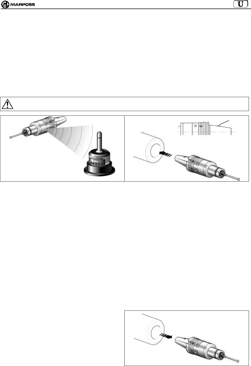
mida 59
6.2 Transmission activation
The transmitter is normally in the stand-by condition. The transmission can be activated in two ways, depending on the transmitter
version:
•radio activation
•mechanical activation (only for Standard Transmitter)
6.2.1 Radio activation
The system is activated after a radio signal is sent from the antenna to the transmitter. The system activation (START) command is
generated by the interface unit in 2 ways:
by connecting the START/STOP input signal to the machine logic (M code)
using the keyboard, by pressing the <select> key for at least 2 seconds.
6.2.2 Mechanical activation
The tool taper is fitted with a microswitch (H). Inserting the taper in the spindle activates the transmission.
Warning:
When you return the transmitter to the tool magazine, make sure that the activation microswitch is not activated.
Figure 6-3. Radio activation. Figure 6-4. Mechanical activation.
6.3 Transmission deactivation
The transmission can be deactivated in various ways, according to the transmitter version.
6.3.1 Transmitter with radio activation
RADIO DEACTIVATION:
1. Machine logic
Transmission deactivated by machine command on the START/STOP input (M code).
2. From Keyboard
by pressing the <select> key for at least 2 seconds.
AUTOMATIC DEACTIVATION
Transmission deactivated when the time set on the transmitter timer elapses
(see sec. 10.2 “Programming the Transmitter" on page 75).
6.3.2 Transmitter with mechanical activation
MECHANICAL DEACTIVATION
Transmission deactivated when the transmitter is removed
from the spindle.
AUTOMATIC DEACTIVATION
Transmission deactivated when the time set on the
transmitter timer elapses
(see sec. 10.2 “Programming the Transmitter" on page 75)
Figure 6-5. Example of mechanical deactivation.
H

ENGLISH
E86N- Touch system with radio transmission
60
7. E86N TRANSMITTER
7.1 Description
There are currently two types of transmitters:
• STANDARD TRANSMITTER
on which the various types of probes are fixed using suitable flanges
• COMPACT TRANSMITTER
with the probe incorporated in the transmitter
The transmitter sends the antenna the following information needed by the CNC to process the measurement:
• Probe status: probe with finger in home position/probe with finger deflected
• Battery status: charged or low
A green LED (L) indicates the status of the probe, the battery and the transmission:
LED permanently lit = Probe with finger deflected
1 flash every 2s = Transmission activated
2 flashes every 2s = Low battery
Standard transmitters may in turn be divided into:
• TRANSMITTERS WITH RADIO ACTIVATION:
The transmission is activated by a signal sent by the antenna.
• TRANSMITTERS WITH MECHANICAL ACTIVATION:
The transmission is activated by the microswitch (H) on the tool taper.
The microswitch is not present in the transmitter with radio activation.
CAUTION: Mechanical activation is only available on Standard transmitters, not on compact transmitters.
For details on how to programme the transmitter see sec. 10.2 “Programming the Transmitter" on page 75.
Table 7-1. Technical specifications.
Power supply: : 9V battery (standard transmitter)
: 6 x 1.5V batteries (compact transmitter)
Transmission distance : 15 m
Figure 7-1. Transmitters.
H
Standard Transmitter Compact Transmitter
LL
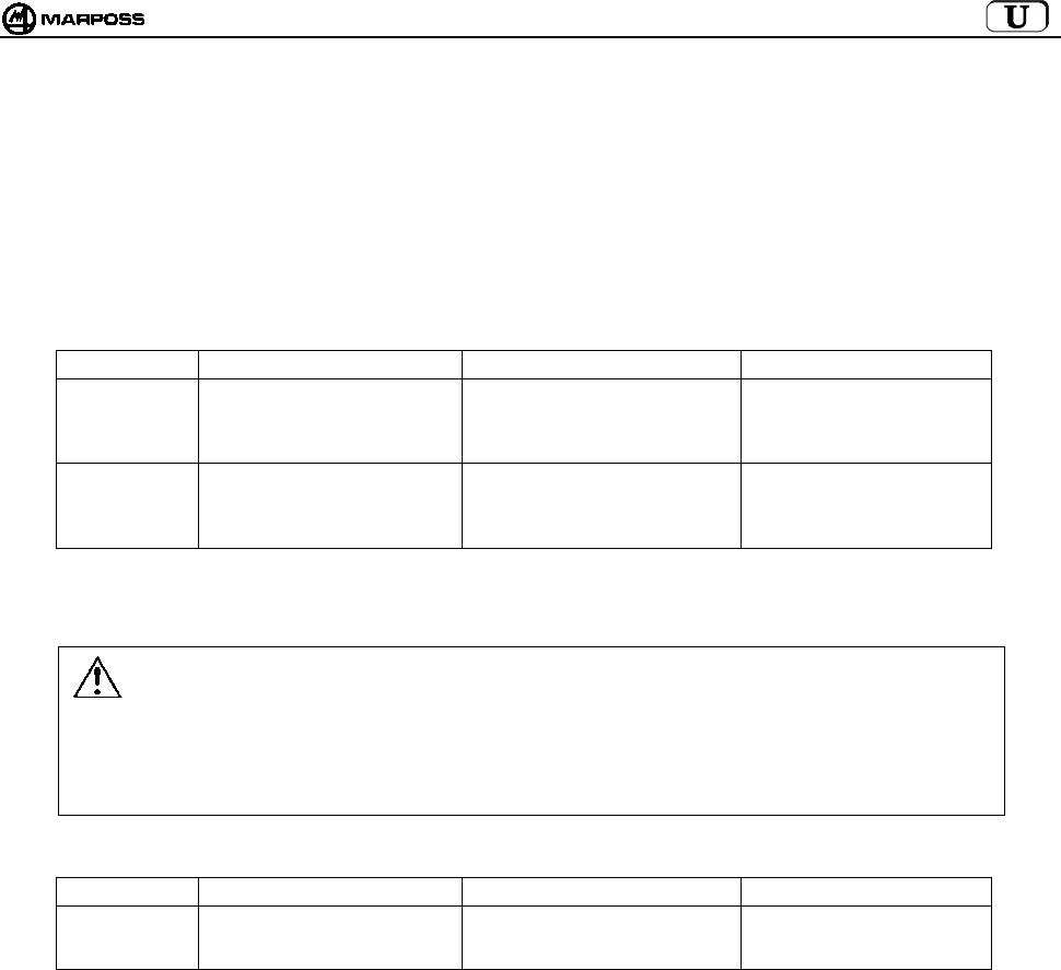
mida 61
7.2 Battery life and indications on the Interface
The transmitter battery charge status is indicated on the interface, both by LEDs (Low Battery LED or Error LED) and on the display
(with the system activated, press the <select> key to view the identification code on the left and the charge level on the right: “7” is the
Max. value and “0” battery completely flat). In particular:
• “Low battery” LED lights up at Level “3” on the display
• “Error” LED lights up at Level “0” on the display
The charge value shown on the display remains in the memory until the next activation.
The battery life depends on the length of time for which the transmitter is operated and the type of battery used. The table below
indicates the battery life according to battery type, with the transmitter operating continuously and in stand-by:
• Standard transmitter
BATTERY TYPE RECOMMENDED BATTERY CONTINUOUS OPERATION STAND-BY OPERATION
Alkaline DURACELL MN1604
DURACELL PC1604 PROCELL
ENERGIZER X22
ENERGIZER 522
150 hours 170 days
Lithium ENERGIZER L522
ULTRALIFE U9VL
DURACELL PL1604
SONNENSCHEIN SLM9-J
320 hours 380 days
Note: An alkaline battery is supplied with the transmitter in the packaging. Insert the battery in the transmitter before
installation (see sec. 15.1.2 “Inserting/Changing the Transmitter Battery on page 88).
Warning:
TRANSMITTER WITH MECHANICAL ACTIVATION
Check that the taper seat in the tool magazine has a shape which prevents activation of the activation
microswitch (H).
LITHIUM BATTERIES: lithium batteries may explode if they are not changed correctly. Only substitute them with
batteries which are the same or of an equivalent type (see table). Always dispose of used batteries in
accordance with the standards in force.
• Compact transmitter
BATTERY TYPE RECOMMENDED BATTERY CONTINUOUS OPERATION STAND-BY OPERATION
DURACELL MN9100
Alkaline
ENERGIZER E90 230 hours 250 days
Note: the batteries are supplied with the transmitter in the packaging.
Insert the batteries in the transmitter before installation (see sec. 15.1.2 “Inserting/Changing the Transmitter
Battery on page 88).
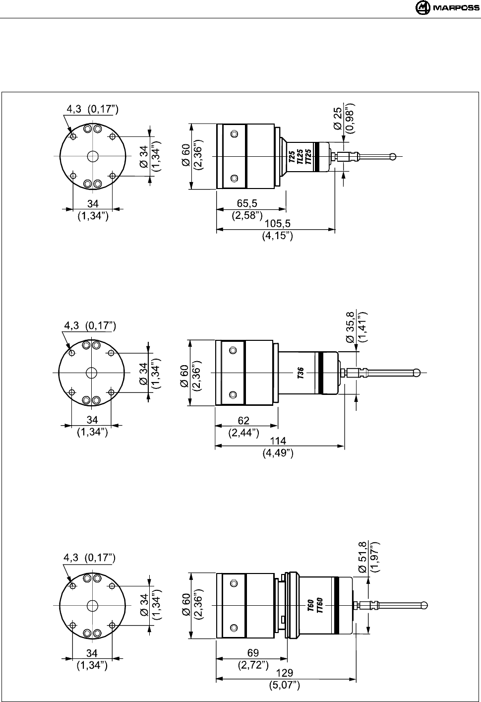
ENGLISH
E86N- Touch system with radio transmission
62
7.3 Dimensions of the transmitter with probes
7.3.1 Standard transmitter with standard flange
Figure 7-2. Dimensions of the transmitter with standard flange.

mida 63
7.3.2 Standard transmitter with adjusting flange
Figure 7-3. Dimensions of the transmitter with adjusting flange.
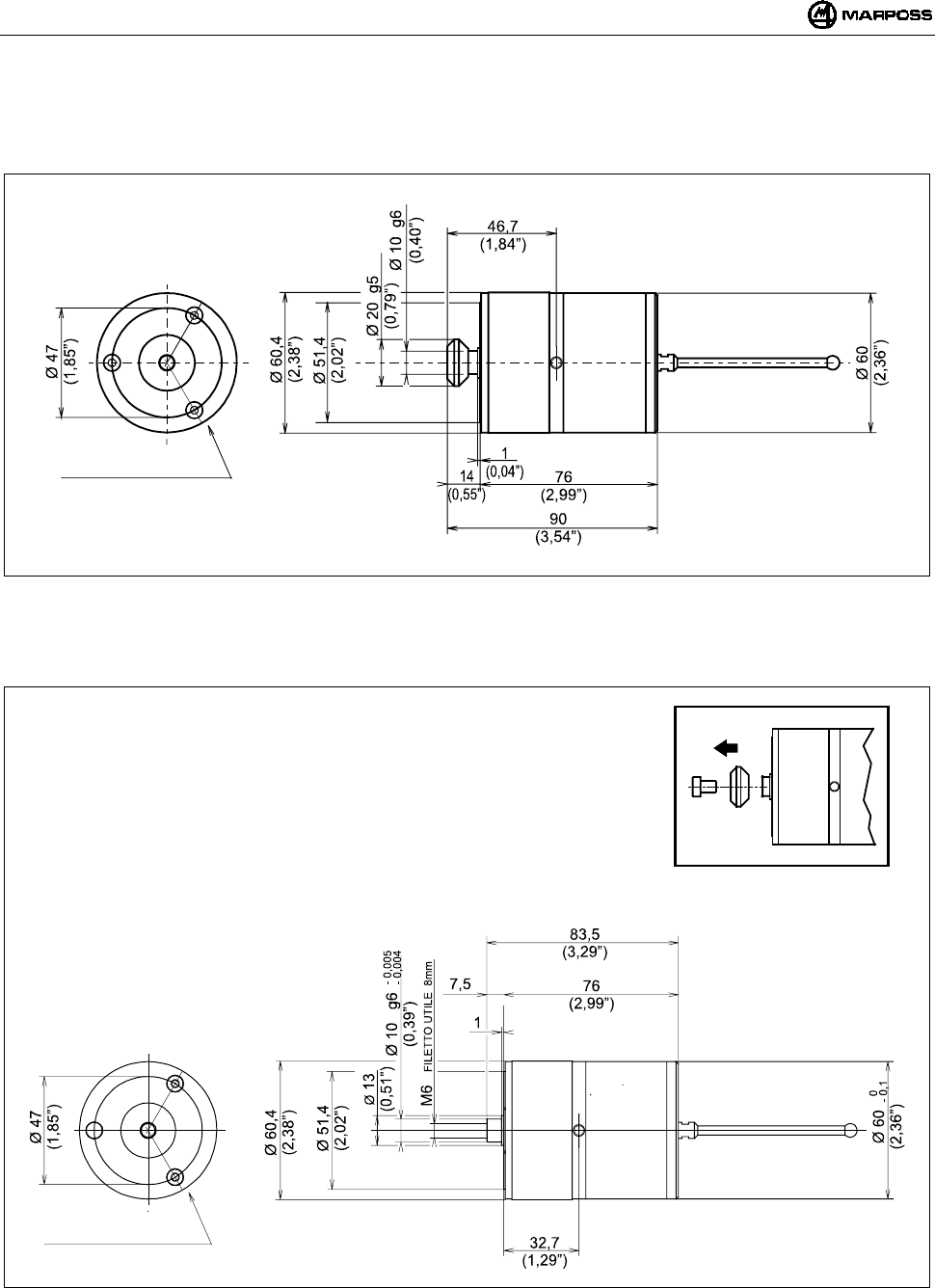
ENGLISH
E86N- Touch system with radio transmission
64
7.4 Dimensions of the compact transmitter
7.4.1 E86N-P compact transmitter
Figure 7-4
7.4.2 E86N-P compact transmitter without conical shank
Figure 7-5
3 SCREWS M4X6
3 SCREWS M4X6
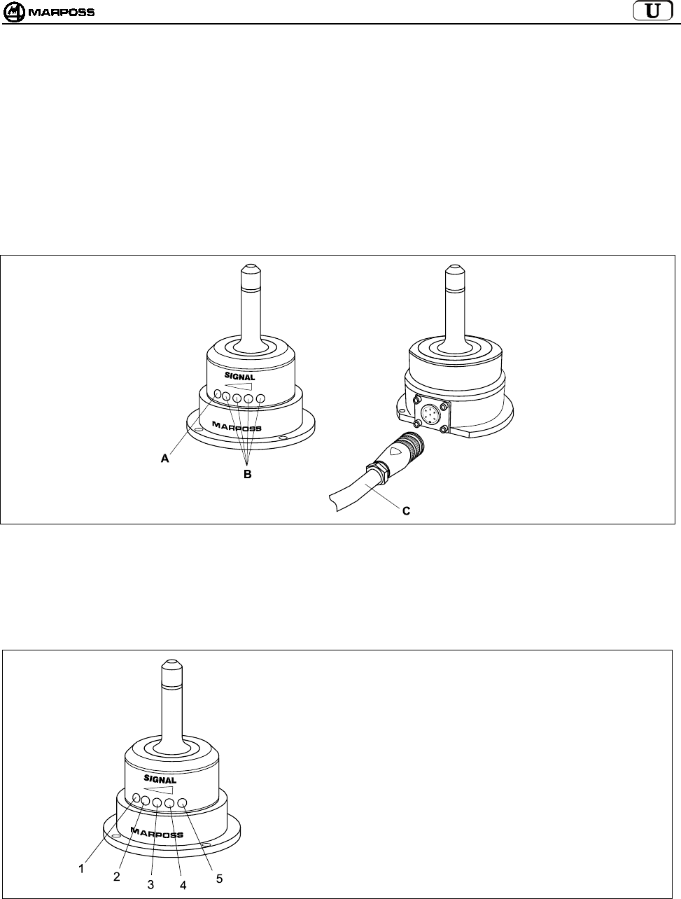
mida 65
8. E86N RECEIVER
8.1 Description of the Antenna and extension with connector
The antenna receives the data issued by the transmitter and sends it to the E86N interface unit to which it is connected by the cable
with connector.
The following are located on the front of the antenna:
A- A red LED. When lit this indicates that the transmission is not in progress or that the transmitter signal is not received.
B- A yellow LED and three green LEDs. These indicate the strength of the signal received. During installation, when these LEDs
light up, it can help correct antenna positioning.
C- Shielded cable with connector (15m or 30m long) for connection to the E86N interface unit.
Figure 8-1: Antenna and cable with connector.
8.2 Remote display mode
The LEDs on the Antenna can also act as a remote display for the interface unit, if the “rd” (remote display) data item is suitably
programmed during interface programming (see sec. 10.1 “Programming the interface” on page 72).
If this is done, the LEDs have the following meanings:
1 -
2 -
3 -
4 -
5 -
RED LED = ERROR
YELLOW LED = LOW BAT
GREEN LED = always OFF
GREEN LED = PROBE
GREEN LED = POWER
Figure 8-2. Antenna operation as a remote panel for the interface unit.
8.3 Connecting up the antenna
Connect the antenna to the E86N interface unit terminal board (see connecting diagram in sec. 9.4 "Connections to the interface unit”
on page 69).
The antenna is supplied without the cable with connector.

ENGLISH
E86N- Touch system with radio transmission
66
8.4 Fitting the antenna
• The antenna can be temporarily secured in place using the magnetic base while you find the most suitable position for it and check
that the signal issued by the transmitter is received during touch probe system movements.
• For permanent fitting, secure the antenna with the four screws supplied.
Figure 8-3
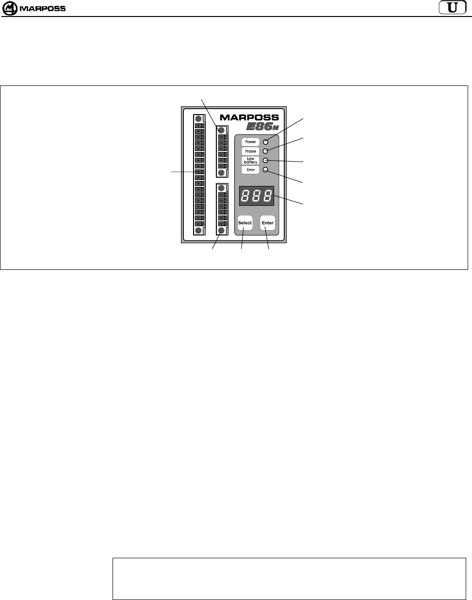
mida 67
9. E86N INTERFACE UNIT
9.1 Interface unit front panel
Figure 9-1: Front panel.
A - “Power” LED (green) : lit when the power supply voltage is present.
B - “Probe” LED (green) : indicates the probe status. Lit when the probe finger is deflected. Off when the probe finger is in the
home position.
C - “Low battery” LED
(yellow)
: lit when the battery is almost flat (see sec. 7.2 “Battery life and indications on the Interface ” on page
61 and LOW BAT output signal sec. 9.4 "Connections to the interface unit” on page 69).
D - “Error” LED (red) : indicates an error condition. Lit when the transmission is not activated, when the probe is outside the
transmission range (see also ERROR output signal sec 9.4 "Connections to the interface unit” on
page 69) and when the battery is completely flat (see sec. 7.2 “Battery life and indications on the
Interface” on page 61).
E - DISPLAY : seven-segment, three-digit LED display. In normal operating conditions, this can show the radio
channel operating, the identification code and the battery charge status.
During programming it shows all programmable values.
F - ENTER KEY : Press for longer than 2 seconds to switch the interface to programming mode.
In programming mode, confirms the selected data item and moves on to the next.
Press for longer than 2 seconds simultaneously with the <Select> key to clear the alarm messages
present on the interface display.
G – SELECT KEY : Press for less than 2 seconds to view the identification code on the left and the battery charge
level on the right
Press for longer than 2 seconds for system manual Activation/Deactivation.
Press for 2 seconds simultaneously with the <Enter> key to clear the alarm messages present on
the interface display.
In programming mode, scans the programmable data or increases the current programming
data item.
H – TERMINAL BOARD : for connecting the single antenna (H1) and the additional antenna (H2).
CAUTION
When using only one Antenna, in order to make it function correctly always connect it to the lower
terminal H1. Otherwise, if you connect it to the upper terminal H2, the system does not function and
the display shows the “E.nb” error message (see sec. 14.1 “Error messages” on page 87).
I - TERMINAL BOARD : For electrical connections to the CNC.
H2
E
G
C
D
I
F
H1
A
B

ENGLISH
E86N- Touch system with radio transmission
68
9.2 Interface unit dimensions
Figure 9-2. Overall dimensions.
9.3 E86N Interface technical specifications
Power supply : 24V DC unstabilised (13.5 - 35 V)
: 300 mA max. (with two antennas connected)
Input Signals : Optoisolated inputs (24V - <10mA)
-AUX IN : Not connected (for future use)
-SEL 0 - SEL 1 : Identification code selection, for selecting up to 4 transmitters on the same machine (see sec. 9.4.1
“Selecting the identification code” on page 69).
24V - 7 mA
-START/STOP : Transmission Activation/Deactivation.
24V – 4mA (High current)
The operating voltage/current of this input can be programmed according to the type of NC connected (see
sec. 10.1 “Programming the interface” on page 72) with the following values:
15V – 0.5 mA (Low current)
Note: The connection of input signals may be of the SINK type (connect “COM” to “+24V”) or the SOURCE type
(connect “COM” to “0V”).
Output Signals : Solid State Relay (SSR) Contacts 50V - 40 mA
-ERROR : Communication error
(probe not activated or outside the transmission range, transmitter battery completely flat with battery level
on display equal to “0”.
N.C. (Normally Closed) contact.
-AUX OUT : Not connected (for future use)
-PROBE 1/SKIP : Signal relative to the status of the probe being used; may be programmed as a probe status signal (in
home position or deflected) or SKIP (pulse).
Programmable N.C. or N.O. (Normally Closed or Normally Open) contact.
-PROBE 2/SKIP : Additional signal relative to the status of the probe being used; may be programmed as a probe status
signal (in home position or deflected) or SKIP (pulse).
Programmable N.C. or N.O. (Normally Closed or Normally Open) contact.
-LOW BAT : Low battery signal with battery level on display equal to “3”.
Using an alkaline battery the remaining continuous system operation in this condition is:
• 14 hours for the Standard transmitter
• 24 hours for the Compact transmitter
Programmable N.C. or N.O. (Normally Closed or Normally Open) contact.
70
(2,76”) 51
(2,01”)
11
(0,43”)
68
(2,68”)
5,5
(0,22”)
90
(3,54”)
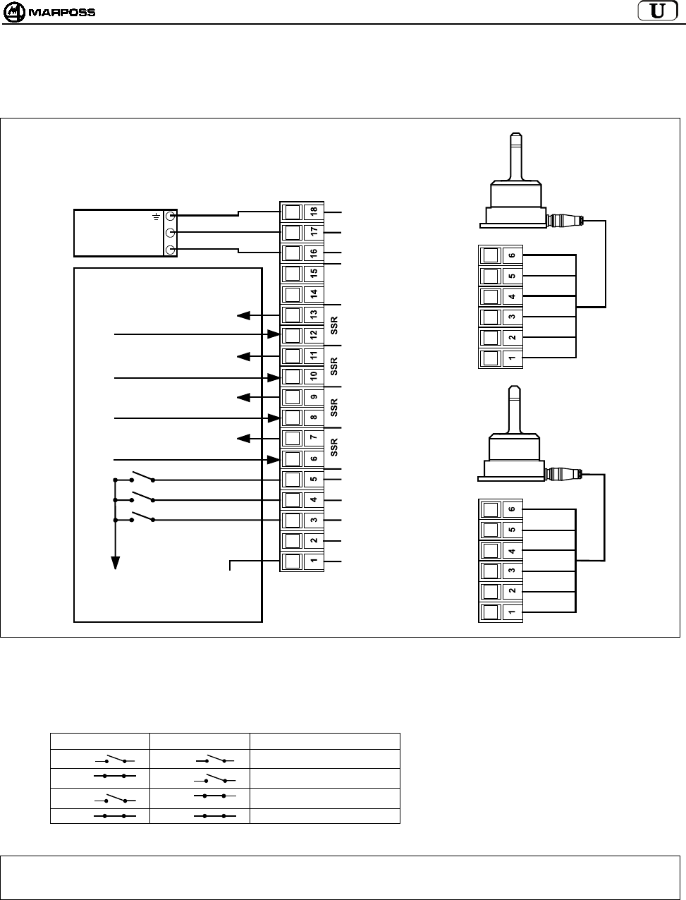
mida 69
9.4 Connections to the interface unit
The unit card is fitted with the connections terminal board. The connections are made using screw connectors.
Figure 9-3. Connections.
9.4.1 Selecting the identification code
Input from logic:
SEL 0 SEL 1 IDENTIFICATION CODE
I1 I2 A
I1 I2 B
I1 I2 C
I1 I2 D
Note: When using a single transmitter, you do NOT need to manage these 2 Inputs from the CNC. The interface default setting for
the identification code is A, with the same for the transmitter (see sec. 10.2 “Programming the Transmitter” on page 75).
SCREEN
ANTENNA 1
ANTENNA 2
GREEN
BLUE
WHITE
PURPLE
RED
GREEN
BLUE
WHITE
PURPLE
SCREEN
RED
COM
A
UX IN
SEL 0
SEL 1
START/STOP
PROBE 1 STATUS
SKIP
PROBE 2 STATUS
SKIP
LOW
BATTERY
ERROR
A
UX OUT
+24V DC
0V
EARTH
MACHINE CONTROL CNC
0V SOURCE
24V SINK
PROBE 1 STATUS/ SKIP
PROBE 2 STATUS/ SKIP
LOW BATTERY
ERROR
24V
0V
PSU
I1
I2
24V SOURCE
0V SINK
(
H1
)
(
H2
)
(
I
)
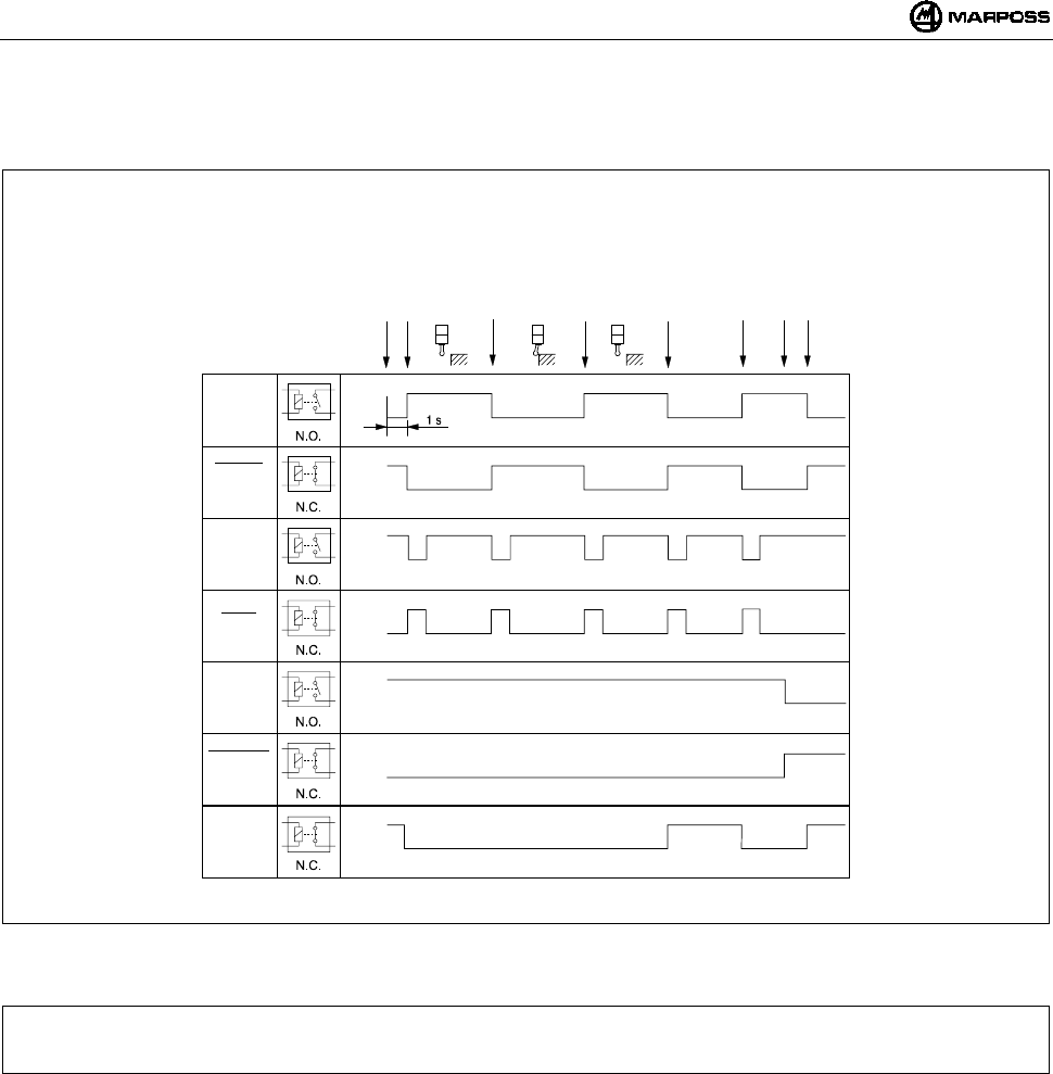
ENGLISH
E86N- Touch system with radio transmission
70
9.5 Diagram of E86N interface unit I/Os
Figure 9-4. Diagram of interface unit I/Os.
NOTE: in some working environments particularly disturbed by electromagnetic interference, the time necessary to activate the
transmission may be longer than 1 second (max. 6).
Open
Closed
Open
Closed
Open
Closed
Open
Closed
Open
Closed
Open
Closed
Open
Closed
Probe
Status
Probe
Status
Skip
Skip
Low
batter
y
Low
batter
y
Error
E86N
signals
solid
state
relay
Start
Probe activated
In home position
Contact opening
Deflected
Contact closing
In home position
Erro
r
Error cleared
Low battery
Probe deactivated
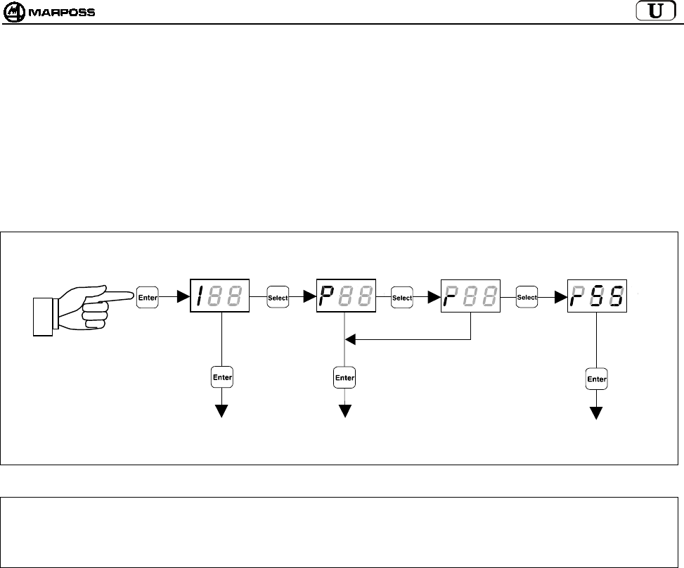
mida 71
10. PROGRAMMING THE SYSTEM
Hold down the “Enter” key for longer than 2 seconds to switch the system to programming mode. Then select the type of programming
with the “Select” key:
I --> Interface Programming
P --> Transmitter Programming
r --> Transmitter Programming in "Recovery" mode
rSS ÆProgramming the “Sniffer” function
When you have made your selection, use the “Select” and “Enter” keys to edit the programming data. The “Select” key increases the
current programming data item, whilst the “Enter” key confirms it and goes to the next item.
CAUTION: If you want to reprogram only the Operating channel, start the procedure from transmitter programming.
In this way, since the interface is supplied with the Automatic channel programming function enabled (AP=1 – see sec.
10.1 “Programming the interface” on page 72) when transmitter operating channel reprogramming is complete, the
interface is also automatically programmed on the same channel.
TRANSMITTER
PROGRAMMING
INTERFACE
PROGRAMMING
TRANSMITTER
PROGRAMMING IN
RECOVERY MODE
> 2 seconds
PROGRAMMING THE
“SNIFFER” FUNCTION
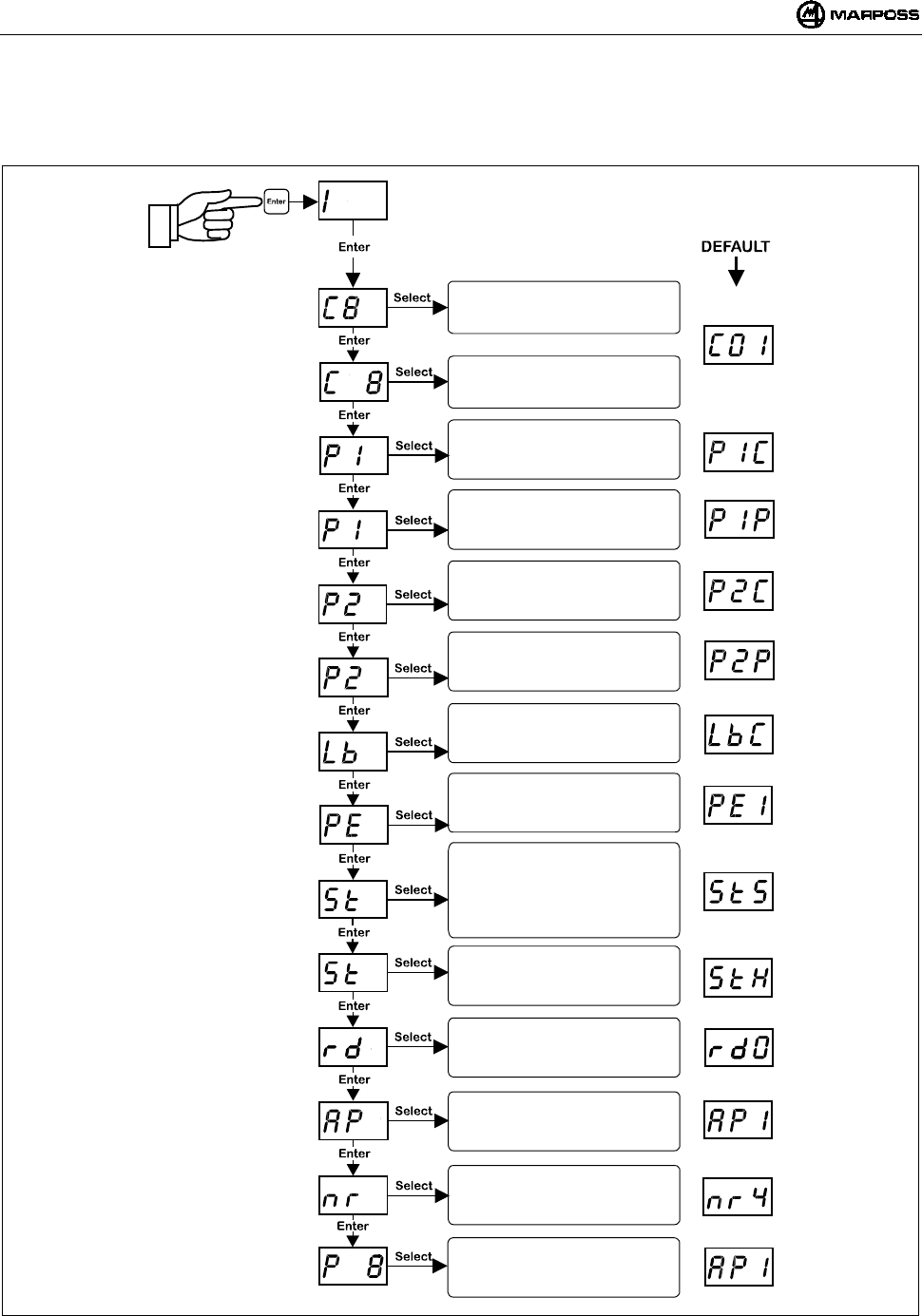
ENGLISH
E86N- Touch system with radio transmission
72
10.1 Programming the interface
Switch to programming mode and select the type of programming "I" with the “Select” and “Enter” keys to edit one or more of the
following values:
Note: after you have confirmed the last data item you exit programming.
However, you can exit programming at any time by holding down the <ENTER> key for longer than 2 seconds, cancelling the
current sequence.
Channel entry:
TENS
Channel entry:
UNITS
Probe 1 output polarity:
P1C= N.C. OUTPUT
P1O= N.O. OUTPUT
Probe 1 output functionality:
P1P= PROBE STATUS
P1S= SKIP
LOW BAT output mode:
LbC= N.C.
LbO= N.O.
PROBE error output:
PE0= Probe at 0 (home)
PE1= Probe at 1(deflected)
START signal:
S= Standard
P= Pulse
r= retrigger
Remote display on base st.:
0= disabled
1= enabled
START input:
L= low current 15V-0.5mA
H= normal current 24V-4mA
A
uto. ch. programming:
0= disabled
1= enabled
Confirm data programmed:
0= not confirmed
1= confirmed
Probe 2 output polarity:
P2C= N.C. OUTPUT
P2O= N.O. OUTPUT
Probe 2 output functionality:
P2P= PROBE STATUS
P2S= SKIP
> 2 seconds
Number of
switch ON/switch OFF attempts
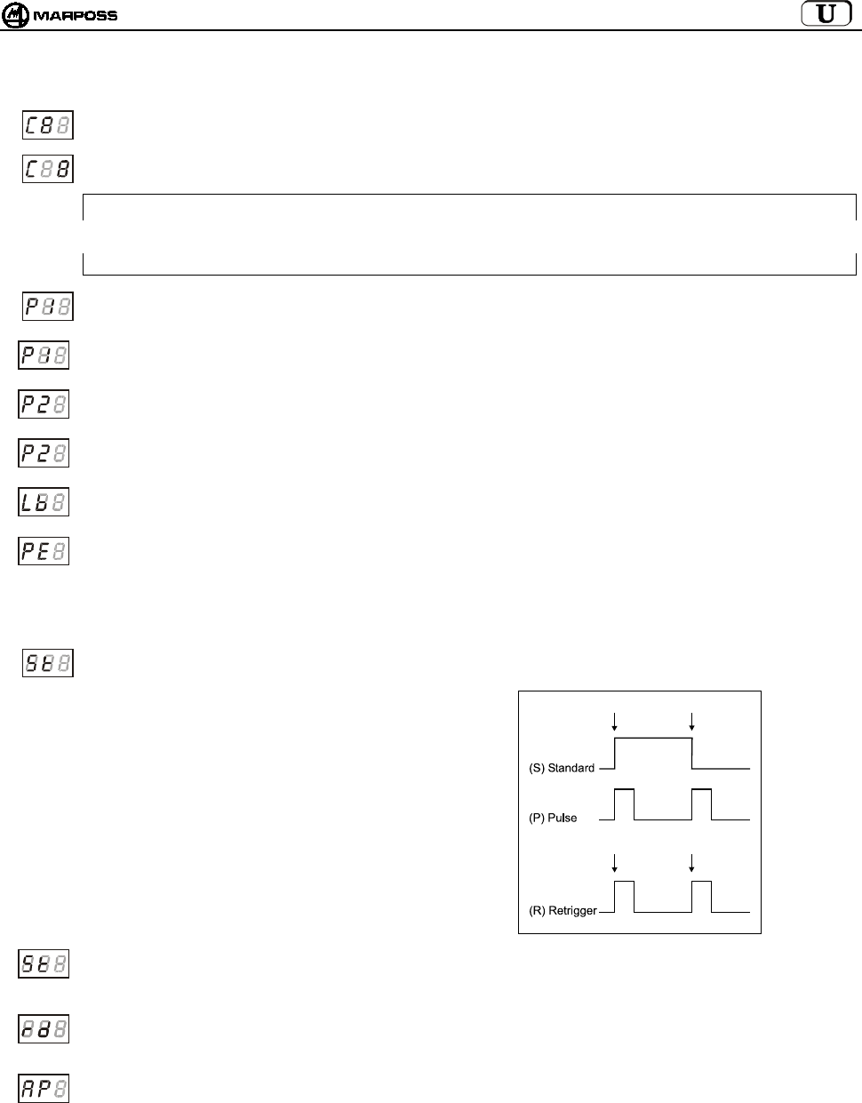
mida 73
Detailed description of interface programming data:
Interface transmission channel – tens: the tens field flashes. Increase it cyclically using the “Select” key.
Interface transmission channel – units: the units field flashes. Increase it cyclically using the “Select” key.
CAUTION:
When you confirm the programming (P1), incorrect selection of channels 65-69 or 00 is considered invalid and the
interface display flashes on the incorrect channel just set. To exit this condition, simply switch to the interface
programming mode again and set the correct channel (from 1 to 64).
PROBE1 output polarity: the first digits show “P1”. The third cyclically takes the values <C> and <O> to indicate
NORMALLY CLOSED and NORMALLY OPEN.
PROBE1 output functionality: the first digits show “P1”. The third cyclically takes the values ‘P’ and ‘S’ to indicate that
the output is of the normal or “skip” type (pulse duration 44ms with each change in the touch signal status).
PROBE2 output polarity: the first digits show “P2”. The third cyclically takes the values <C> and <O> to indicate
NORMALLY CLOSED and NORMALLY OPEN.
PROBE2 output functionality: the first digits show “P2”. The third cyclically takes the values ‘P’ and ‘S’ to indicate that
the output is of the normal or “skip” type (pulse duration 44ms with each change in the touch signal status).
LOW_BAT output polarity: the first digits show “lb” The third cyclically takes the values <C> and <O> to indicate
normally closed and normally open.
Probe error output: allows you to programme the status of the PROBE1 and PROBE2 outputs in error conditions:
- transmitter not activated
- transmitter out of range
- battery completely flat
The first digits show “PE”. The third cyclically takes the values <0> (probe in home position) and <1> (probe deflected).
Start signal operating mode: the first digits show “St”.
The third cyclically takes the values ‘S’ (standard), ‘P’ (Pulse) and ‘r’ (retrigger).
In “standard” mode the leading edge
activates the probe and the trailing edge
deactivates it.
In “pulse” mode the leading edge changes
the probe status, if the probe is in the
deactivated state it is activated, if it is in the
activated state it is deactivated.
Finally, in “retrigger” mode the probe
cannot be deactivated using the radio
system, and a leading edge on the Start
signal when the probe is still active
retriggers the transmitter timer. This means
that the transmitter can only be switched off
by means of the timer.
Start input current: the first digits show “St”. The third cyclically takes the values ‘L’ (Low current) and ‘H’ (High
current). In “low current” mode the input absorbs approx. 0.5mA at 15V (*Note). In “high current” mode the input is
standard and absorbs approx. 4mA at 24V.
Antenna remote display: the first digits show “rd”. The third cyclically takes the values <0> (disabled, the base station
LEDs indicate the radio signal level) and <1> (enabled, the base station LEDs show the indications on the interface
LEDs, except the base station central green LED which is always Off) (see 8.2 “Remote display mode” on page 65.
Automatic interface channel programming: the first digits show “AP”. The third cyclically takes the values <0>
(disabled, transmitter channel programming has no effect on the interface value programmed) and <1> (enabled, at the
end of transmitter programming the interface channel is made the same as that being programmed on the transmitter
(see sec. 10.2 “Programming the Transmitter” on page 75).
* Nota: This function is anable using the extension cable cod.6739696319.
Activation
Activation
Deactivation
Retrigger
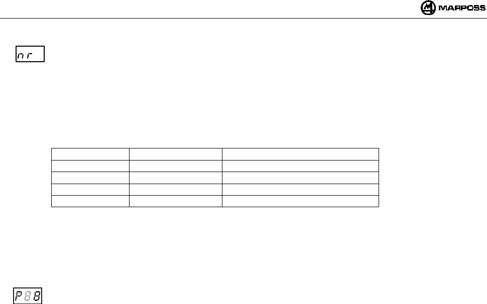
ENGLISH
E86N- Touch system with radio transmission
74
number of switch on/switch off attempts: the first 2 digits indicate the text “nr”.
the third cyclically assumes values from 2 to 9 (default is 4).
this data item allows programming of the maximum number of attempts that the base station makes to switch the
transmitter on/off. when said number of attempts is reached, if the transmitter has not be switched on/off, the interface
must be provided with a new command by means of the start signal.
increasing the number of attempts causes a significant delay in the switch on/switch off time.
for the default value (nr=4) the switch on/switch off times are as shown in the table:
TYPICAL MAX. VALUE IDENTIFICATION CODE
1.050 sec 4.200 sec A
1.200 sec 4.800 sec B
1.350 sec 5.400 sec C
1.500 sec 6.000 sec D
if the number of attempts is changed the values in the table are modified according to this equation:
delay = default delay x (nr / 4)
as shown in the table, the switch on/switch off time also depends on the identification code used (sub-channel).
the greater the distance between the codes, the smaller the probability of switch on/switch off failure, in situations with
high density close applications.
Confirm data programmed: The first digit shows “P”. The third cyclically takes the values <0> for do not programme
the interface and <1> for program the interface.

mida 75
10.2 Programming the Transmitter
Switch to programming mode and select the type of programming "P" with the “Select” and “Enter” keys to edit the following values one
at a time:
Note: after confirming the last data item you exit programming and the transmitter is deactivated.
However, you can exit programming at any time, by holding down the <ENTER> key for longer than 2 seconds, cancelling
the current sequence.
(
∗
) Note: depends on the type of transmitter:
- for a transmitter with radio activation, the activation mode parameter is set to radio activation and the switch off time
value is <5>, corresponding to 2'14"
- for a transmitter with mechanical activation, the activation mode parameter is set to mechanical activation and the
switch off time value is <8>, corresponding to an infinite switch off time.
Channel entry:
TENS
Channel entry:
UNITS
Identification code:
(A, B, C, D)
A
ctivation mode:
0= Radio
1= Mechanical
Operating time:
0= 4"
1= 8"
2= 17"
3= 34"
4= 1'7"
5= 2'14"
6= 4'28"
7= 8'57"
8=
∞
Timer Rettriggering:
0= Disabled
1= Enabled
Confirm data programmed:
0= do not confirm
1= confirm
> 2 seconds
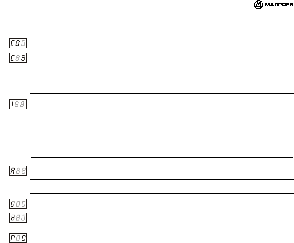
ENGLISH
E86N- Touch system with radio transmission
76
Detailed description of transmitter programming data:
Transmission channel – tens:
the tens field flashes. Increase it cyclically from the value <0> to the value <6>.
Transmission channel – units: the units field flashes. Increase it cyclically from the value <0> to the value <9>.
CAUTION:
When you confirm the programming (P1), incorrect selection of channels 65-69 or 00 is considered invalid and the
interface display flashes up the channel on which the interface is set and the transmitter can only be reset in “recovery”
mode (see sec.10.3 “Programming the transmitter in Recovery mode” on page 77).
Identification code: the first digit shows “I”. The third may be selected from values <A, B, C, D>.
CAUTION:
A transmitter is completely identified by the operating channel number and by the identification code (e.g.: 12B).
Since the identification code is programmable for the transmitter but it is an external logic (CNC) input for the interface,
we recommend that you only change this parameter on the transmitter if you are sure that it is the same as that of the
Interface; if it is not, the system will not work due to the lack of communication and the only way to reset it will be to
perform a transmitter programming procedure in “Recovery” mode (see sec. 10.3 “Programming the transmitter in
Recovery mode” on page 77).
Activation mode: the first digit shows “A”. The third cyclically takes the values <0> for radio activation and <1> for
mechanical activation.
CAUTION:
Leave the default value shown on the previous page.
Operating time: the first digit shows “t”. Set the third to a value between <0 and 8>, corresponding to an operating time
ranging from a minimum of 4” (value 0) to infinity (value 8).
Timer retriggering: the first digit shows “r”. The third cyclically takes the values <0> for retrigger disabled and <1> for
retrigger enabled.
This data item allows you to reset the timer after each change in the probe status.
Confirm data programmed. The first digit shows “P”. The third cyclically takes the values <0> for do not programme
the transmitter and <1> for programme it.
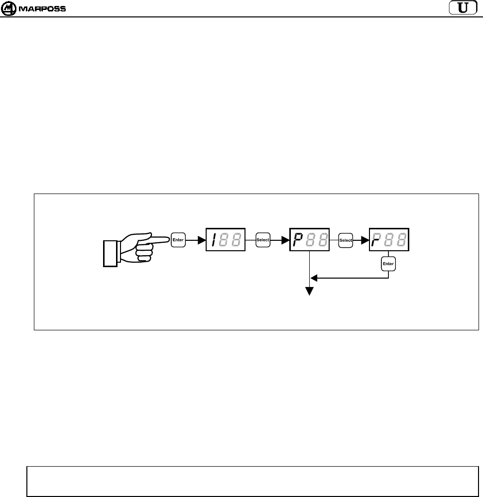
mida 77
10.3 Programming the transmitter in Recovery mode
If the transmitter is in one of the following conditions:
d. unknown transmitter transmission channel
e. transmission channel incorrectly programmed (e.g.: 65-69 or 00)
f. identification code incorrectly programmed (different to that of the interface)
the transmitter “recovery” programming procedure is required, which allows you to view and if necessary change transmitter
parameters.
Recovery procedure:
7. Leaving the interface powered up, power down the transmitter (unscrew the battery cover for the transmitter with radio
activation or open the microswitch on the taper for the transmitter with mechanical activation).
8. From the interface switch to programming mode and select programming type "r".
9. Press <ENTER> on the display and the "REC" message appears.
10. Deflect the finger and hold it there while you power up the transmitter (close the battery cover for the transmitter with radio
activation or close the microswitch on the taper for the transmitter with mechanical activation).
11. The transmitter is activated on a service channel rather than on the programmed channel and the “REC” message is cleared
from the interface display, which instead shows the channel number (with the tens flashing) on which the transmitter was
programmed.
12. Release the finger, keeping the transmitter powered up (cover closed/microswitch on taper closed).
When you have obtained the required information, you can
• exit the programming mode
holding down the <ENTER> key for longer than 2 seconds or by simply releasing the cover/microswitch
• perform a normal transmitter programming procedure as described in sec. 10.2 “Programming the Transmitter” on page 75.
CAUTION: If “Automatic channel programming” is enabled in the interface (AP=1 – see sec. 10.1 “Programming the
interface”), when transmitter programming is complete, the interface channel also changes, so that it is the
same as that on the transmitter.
> 2 seconds
PROGRAMMING THE
TRANSMITTER
(
see sec. 10.2
)
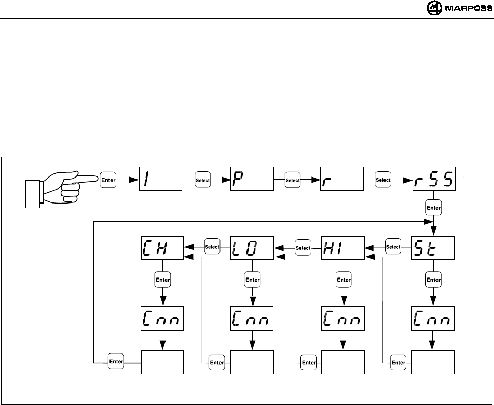
ENGLISH
E86N- Touch system with radio transmission
78
10.4 Analysis of electromagnetic spectrum occupation (“SNIFFER” function)
Electromagnetic spectrum occupation analysis is performed in two steps:
• Scan
The E86N interface cyclically scans all 64 channels, saving the maximum amplitude of the signal received for each channel;
• Viewing results
The E86N interface displays the channels and the maximum amplitude saved during the previous scan.
To activate the function, set the interface to “Programming Mode” (press “Enter” for longer than 2 seconds), press the “Select” key
several times until the display shows the text “rSS”, then press “Enter”.
XX XX XX XX
> 2 seconds
> 2 seconds > 2 seconds > 2 seconds > 2 seconds
Enter=List ▲
Select= List ▼’
Enter=List ▲
Select= List ▼’
Enter=List ▲
Select= List ▼’
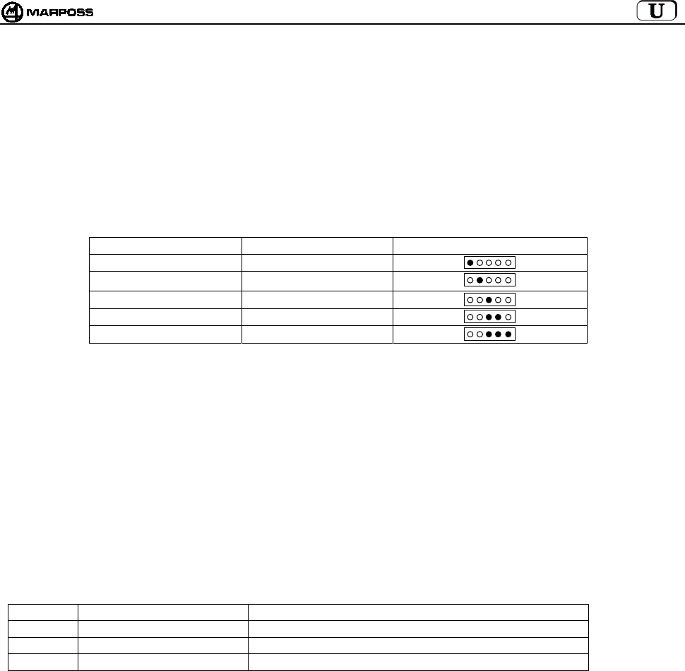
mida 79
10.4.1 Scan
Press “Select” until “St” (Start) appears on the display.
Press “Enter” to start the scan, which continues until you press the “Enter” key for longer than 2 seconds again.
The scan can be left ON even for long periods.
During the scan the “Select” key is not active.
The following appear on the display in sequence:
• the number of the channel acquired “Cnn” (nn= channel number 01-64, as well as activation channel “CA”)
• the corresponding signal amplitude “XX”.
The signal amplitude is expressed in a logarithmic scale and may vary from –9 to 99 (see the table below).
SIGNAL LEVEL VALUE DISPLAYED BASE STATION LED
under limit ≤ -1
much down (1) 0 / 3
down 4 / 7
medium 8 / 11
up ≥ 12
NOTES:
1. The value <0> corresponds to the minimum signal level considered “clear” (Amplitude –102dBm and Signal/Noise ratio > -
12dB).
2. When the scan function is ON, all other functions are OFF (the status of E86N outputs is the same as in an error condition).
3. The maximum values acquired are saved in a non-retentive memory and are therefore lost at switch off.
4. When a scan is started the previous maximum values acquired are deleted.
5. The scan time is approximately 1 second per channel, therefore a complete scan takes around 70 seconds. Since the system
can acquire only one channel at a time, the probability of detecting short-lived electromagnetic signals is increased by
extending the period of observation.
6. The values acquired are only made available after at least one full scan has been performed.
7. If there are two base stations, the highest of the two data items acquired is used.
10.4.2 Viewing results
Scan results may be viewed with three different types of systems:
Symbol System First element in list
HI Decreasing signal received Channel on which signal with maximum amplitude was received
LO Increasing signal received Channel on which signal with minimum amplitude was received
CH Increasing channel number Channel 00
To view the results press “Select” until the symbol corresponding to the desired system appears on the display, then press “Enter”.
The display shows first the channel number and then the signal value.
• Press “Enter” to go to the next item in the list until you get to the last item.
• Press “Select” to return to the previous item, until you get to the first item.
• Press “Enter” for longer than 2 seconds to exit list scrolling.
Re
d
Yello
w
Green
Green
Green
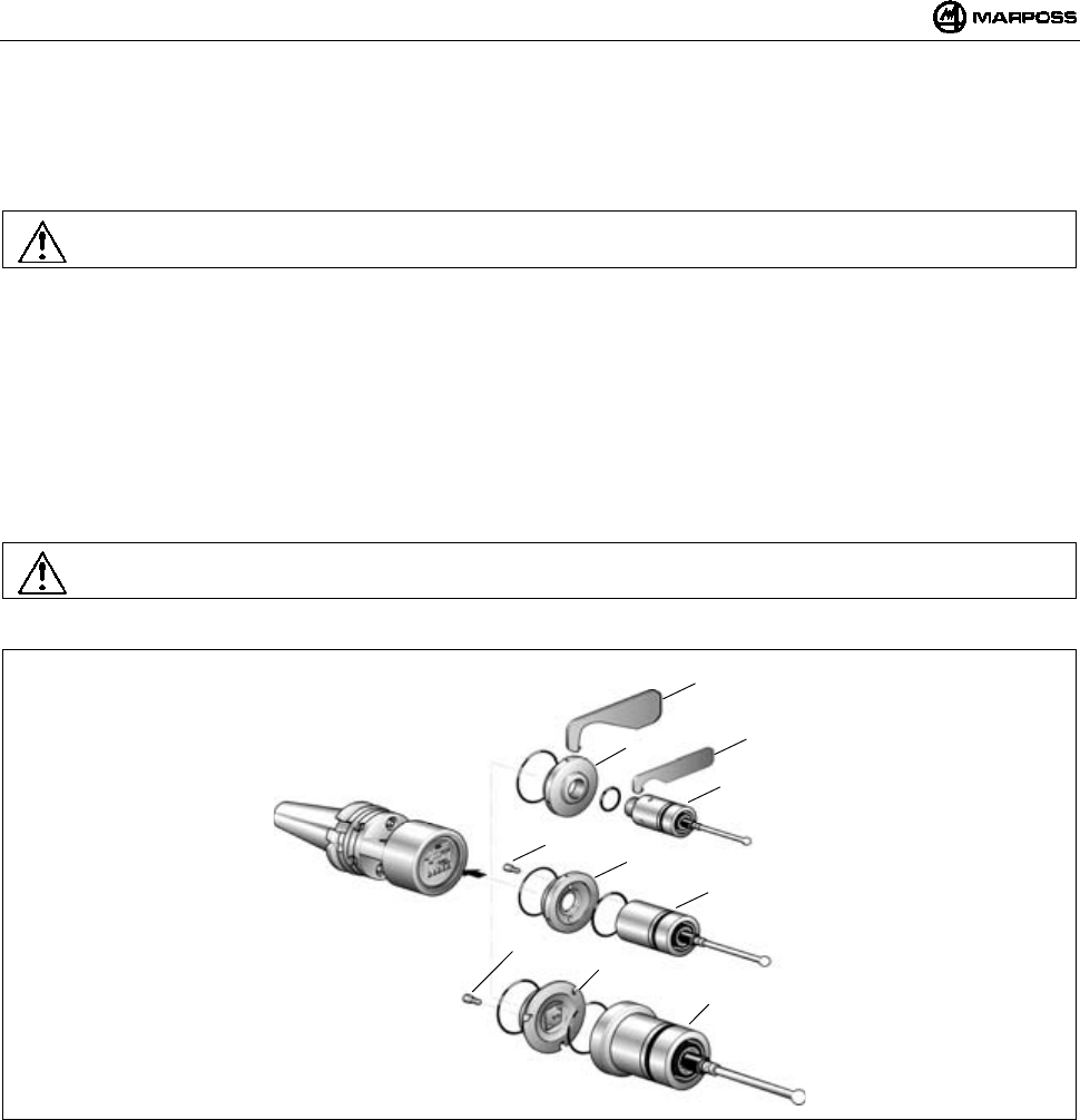
ENGLISH
E86N- Touch system with radio transmission
80
11. FITTING THE PROBE – STANDARD TRANSMITTER
11.1 Fitting the probe – standard transmitter
To fit or remove the transmitter probe proceed as follows:
Warning:
When fitting the probe make sure that the O-rings are in excellent condition and are correctly positioned in their seats.
T25/TL25/TT25 PROBE
- screw the flange (A) onto the transmitter with the wrench (A1);
- screw the probe onto the flange (A) with the wrench supplied (A2).
T36 PROBE
- secure the probe to the flange (B) with the screws (B1);
- screw the flange (B) to the transmitter with the wrench supplied.
T60/TT60 PROBE
- secure the probe to the flange (C) with the screws (C1);
- screw the flange (C) to the transmitter with the wrench supplied;
Warning:
When the operation is complete, align the system.
Figure 11-1
A
2
A
T25/TL25/TT25
B1 B
T36
C1
C
T60/TT60
A
1

mida 81
11.2 Inserting probe extensions (optional)
Extensions are inserted between the probe and the transmitter to increase the system measuring depth. To insert extensions proceed
as follows.
Warning:
When inserting an extension make sure that the O-rings are in excellent condition and are correctly positioned in their seats.
• Extension for T25/TL25/TT25 probe
- Remove the probe from the transmitter with the wrench (A1) supplied.
- Insert the extension (A2) between the probe and transmitter with the relative O-rings.
- Tighten the unit with the wrench (A1) supplied.
Figure 11-2
• Extension for T36 probe
- Unscrew the flange (B) from the transmitter.
- Remove the probe from the flange (B) by taking out the screws (B1).
- Secure the extension (B2) to the flange (B) with the screws (B1).
- Tighten the flange/extension unit to the transmitter with the wrench supplied.
- Secure the probe to the extension with the screws (B3).
• Extension for T60/TT60 probe
- Unscrew the flange (C) from the transmitter.
- Remove the probe from the flange (C) by taking out the screws (C1).
- Secure the extension (C2) to the flange (C) with the screws (C1).
- Tighten the flange/extension unit to the transmitter with the wrench supplied.
- Secure the probe to the extension with the screws (C3).
Figure 11-3
A
2
A
T25/TL25/TT25
C3
B1
T36
T60/TT60
BB3
B2
C1
C
C2
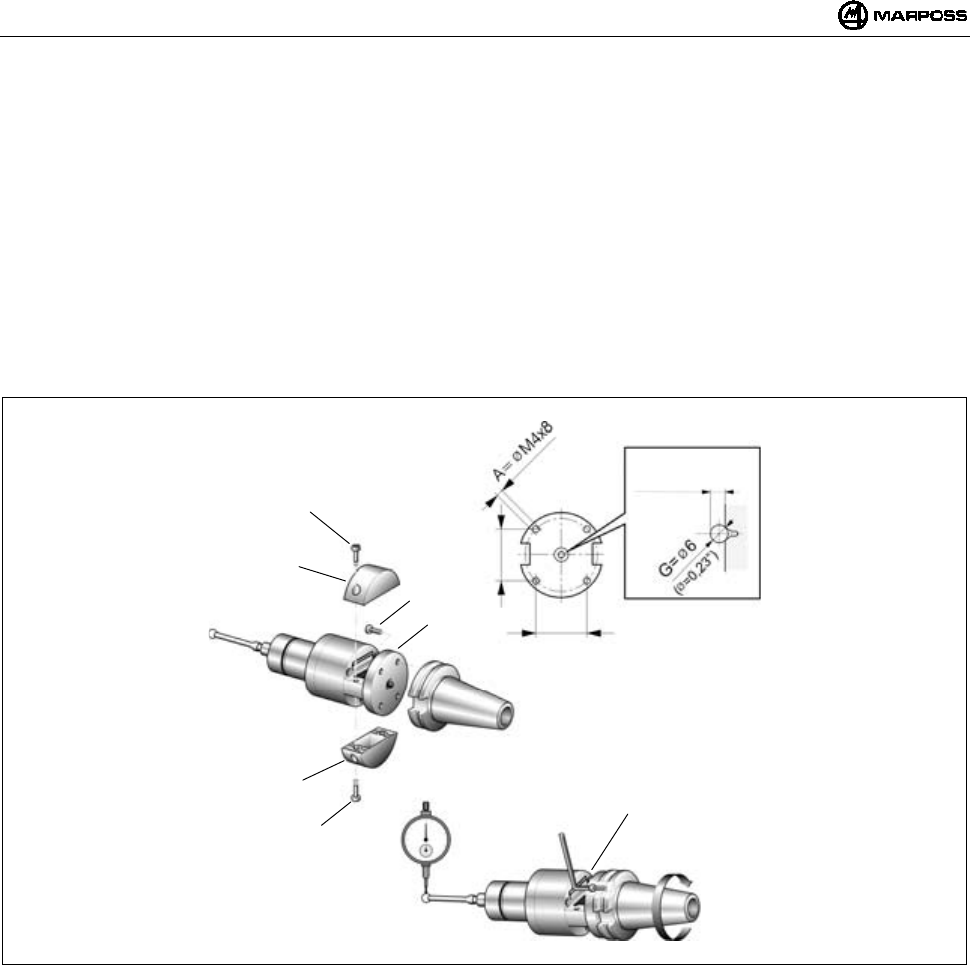
ENGLISH
E86N- Touch system with radio transmission
82
12. FITTING THE TRANSMITTER
12.1 Fitting the Standard transmitter on the taper
- Remove the transmitter battery covers (C) - screws (D) – to gain access to the four holes (E) on the flange. You can fix the
transmitter with a standard flange in two different ways:
- Make four threaded holes M4x8 (A) and a central countersunk area (B) in the taper, as illustrated in Figure 12-1.
- Insert the ø6 mm ball (G) supplied between the transmitter and the taper.
- Secure the transmitter to the taper with the four screws (F).
Aligning the system
- Fit the probe finger (see "Fitting the probe finger").
- Align the centre of the finger ball with the taper axis using the four screws (F).
- When the system is aligned, tighten the four screws (F) in a cross sequence.
Figure 12-1
F
E
D
C
D
C
F
34
(1,34”)
34
(1,34”)
4,5
±
0,1 mm
(0,177 ± 0,004)
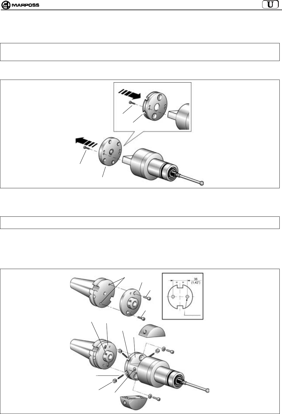
mida 83
12.2 Fitting the Standard transmitter on the taper with adjusting flange
1. Remove the transmitter battery covers by taking out the screws (see section 12.1).
Note: The operations described in points 2 - 3 - 4 and 5 only apply to a transmitter with radio activation. A transmitter with
mechanical activation (microswitch on taper) is supplied, complete with tool taper, with adjusting flanges already
fitted. In the latter case, proceed from point 6.
2- Remove the standard flange (C) from the transmitter by taking out the four screws (D).
3- Secure the adjusting flange (E) to the transmitter with the four screws (D).
Figure 12-2
4. Make two threaded holes M4x8 (F) in the tool taper.
5. Secure the adjusting flange (G) to the tool taper with the two screws (H).
Note: To facilitate transmitter LED (L) angling towards the operator, there are three pairs of fixing holes, allowing you to
select the most suitable angle.
6. Join the two units (transmitter and tool taper), aligning the four threaded holes (M) in the taper flange (G) with the four slots (N) in
the transmitter flange (E).
7. Insert the four threaded stud bolts (P) in the slots (N) and tighten them in the threaded holes (M) in the taper flange with the
hexagon wrench supplied.
8. Tighten the four special nuts (Q) on the stud bolts.
Figure 12-3
C
D
D
E
P
QL
MG
N
E
FG
H
H
F=M4x8
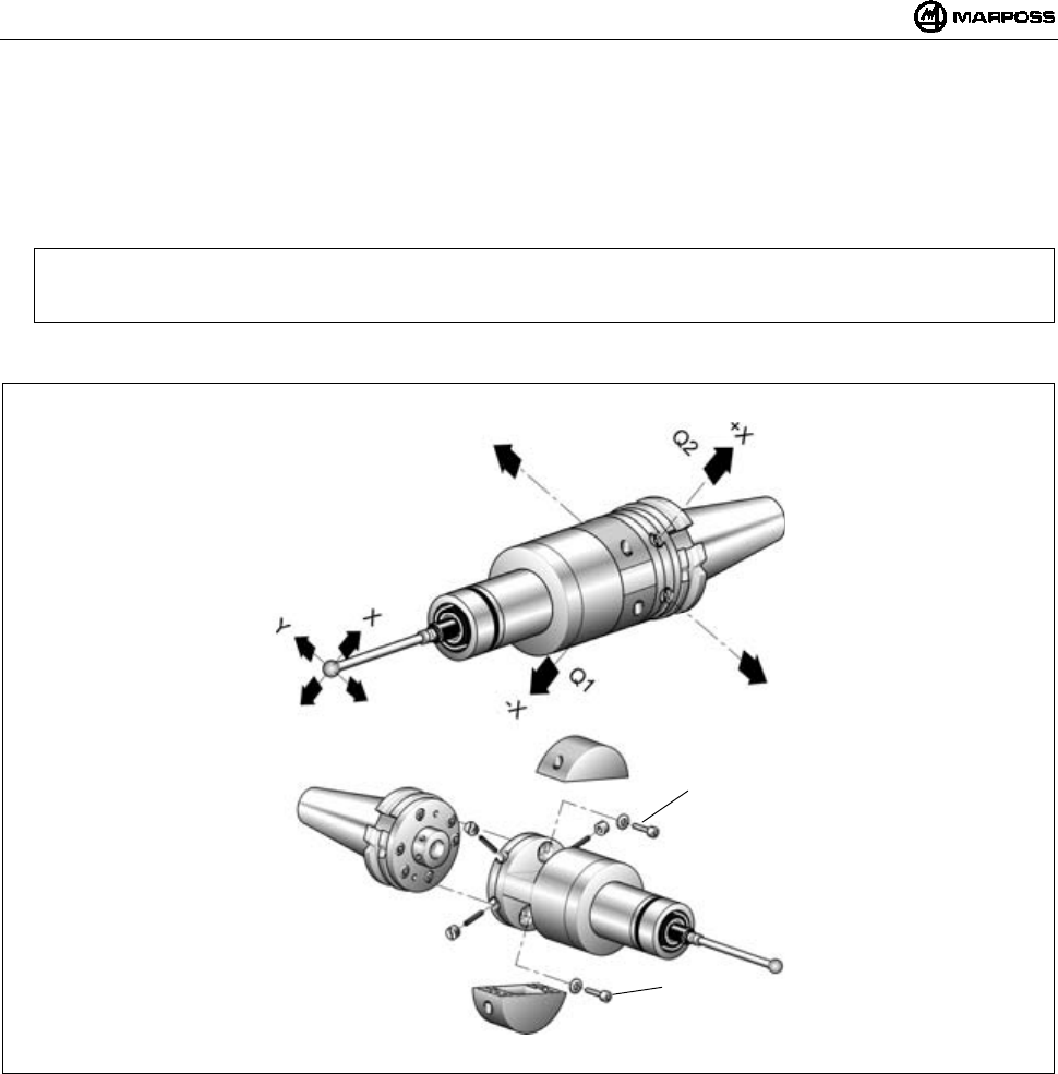
ENGLISH
E86N- Touch system with radio transmission
84
Aligning the system
9. Fit the probe finger (see "Fitting the probe finger").
10. Align the centre of the finger ball with the taper axis using the four special nuts (Q). The maximum movement allowed in the four
directions is 1.7 mm.
Example:
Finger ball movement towards "-X" —> loosen (Q1) and tighten (Q2).
Do the same for the other directions.
11. Once the system is aligned, lock the adjusting unit; insert and tighten the two locking screws (R).
Figure 12-4
R
R
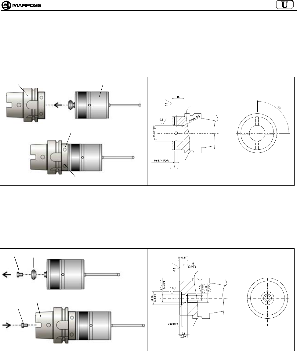
mida 85
12.3 Fitting the E86N-P compact transmitter on the taper
12.3.1 Fixing the E86N-P transmitter to the taper (working on the taper)
• Insert the taper (A) in the transmitter (B).
• Secure the transmitter with 4 grub screws in the holes (C).
Figure 12-5. Securing the transmitter to the taper. Figure 12-6. Working on the taper.
12.3.2 Fixing the E86N-P transmitter without conical shank to the taper (working on the taper)
• Unscrew the screw (A) which secures the conical shank to the transmitter (B).
• Insert the taper (C) in the transmitter (B).
• Secure the transmitter with the screw (A).
Figure 12-7. Fixing the transmitter to the taper. Figure 12-8. Working on the taper.
A
B
C
C
A
B
C
A
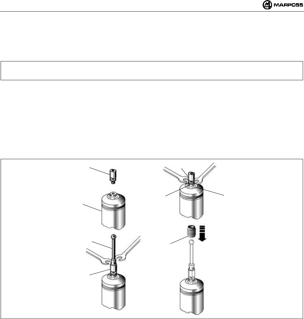
ENGLISH
E86N- Touch system with radio transmission
86
13. FITTING THE FINGER
The following is a description of the procedure for fitting the finger on the probe mounted on a standard transmitter, but since the
compact transmitter incorporates the probe and the finger holder is identical, the procedure is the same for both types of transmitters.
To fit the finger on the probe proceed as follows:
Note: The procedure described below involves use of the crash protection pin. Said pin, inserted between the finger and
the probe, is designed to protect the probe in the event of accidental collisions affecting the finger (the probe finger
is detached).
- Insert the crash protection pin (A) on the probe (B).
- Use the wrench (supplied) to hold the probe finger holder (C) still and tighten the crash protection pin (A) with the other wrench.
Insert the pin (A) tightening wrench in the lower part of the pin - position (D).
- Screw the finger (F) onto the crash protection pin (A).
- Use one wrench to hold the pin still and the other to tighten the finger.
- Insert the retainer (E), sliding it along the finger until it surrounds the crash protection pin (A). The retainer is designed to hold the
finger if the pin breaks.
- In applications with radio transmission we recommend the use of styluses
- Which are ceramic rather than made of steel, to avoid any (unlikely) interference. If the crash protection pin is not used, screw the
finger directly onto the probe; using one wrench to hold the finger holder (C) still and the other to tighten the finger.
Figure 13-1
A
B
F
A
A
DC
E
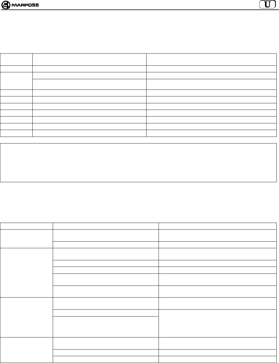
mida 87
14. DIAGNOSTICS
14.1 Error messages
The following Error messages may appear on the E86N interface unit display:
ALARM
MESSAGE
CAUSE SOLUTION
E.E2 Read/write error Contact the Technical Assistance service or reprogram all of the data.
E.nb No antenna connected Check the connection to the antenna.
Incorrect antenna connection Check that if there is only one antenna it is connected to the lower
terminal (H1) on the interface.
E.b1 Error communicating with antenna 1 Check the connection to antenna 1.
E.b2 Error communicating with antenna 2 Check the connection to antenna 2.
F.P1 Fault (short-circuit) on PROBE 1 output Check the connection to the PROBE 1 output.
F.P2 Fault (short-circuit) on PROBE 2 output Check the connection to the PROBE 2 output.
F. Er Fault (short-circuit) on ERROR output Check the connection to the ERROR output.
F. Lb Fault (short-circuit) on LOW_BAT output Check the connection to the LOW_BAT output.
F. Au Fault (short-circuit) on AUX output Check the connection to the AUX output.
Note: After the causes of the errors have been eliminated, you can clear the indications from the display by pressing the <Select>
and <Enter> keys simultaneously for longer than 2 seconds (except messages E.b1 and E.b2 which are cleared when you
power down then power up again).
CAUTION:
All system switch off and switch on operations must be performed with the antenna connector(s) connected.
14.2 LED indications
The LEDs on the interface unit panel can give the following indications:
CAUSE SOLUTION
No power supply Check for voltage at the ends of terminals 16 and 17 on
the interface unit terminal board.
"POWER" LED OFF
Resettable fuse open Wait several minutes with the interface powered down.
Transmitter – antenna outside transmission range Make sure that during probe movements the green
""tuning"" LED on the receiver remains lit.
Transmitter battery completely flat or missing Change the battery
Transmission time elapsed Give a start signal to reactivate the system.
No electrical connection between antenna and
interface
Check the receiver cable and the relative connections
to the interface.
"ERROR" LED ON
Electrical or electromagnetic interference Move the cable from the antenna away from any power
cables. Change the operating channel.
No electrical connection between probe and
transmitter.
Check the connection between the probe and the
transmitter.
Probe damaged
"PROBE" LED:
DOES NOT CHANGE
STATUS WHEN
PROBE TOUCHES Transmitter damaged
Remove the probe from the transmitter, connect the
sprung contacts to one another and interrupt the
contact. If despite this the LED does not change status,
the transmitter is faulty. If it changes status, the probe is
faulty.
Loose finger Check that the finger and crash protection pin (if used)
are tightened on the probe.
Loose flange Tighten all of the screws.
POOR
REPEATABILITY
Internal seal pierced or damaged. Substitute the probe.
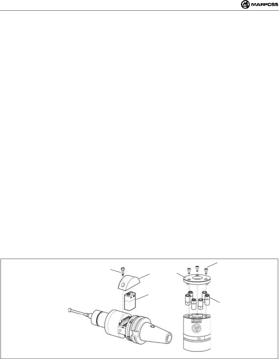
ENGLISH
E86N- Touch system with radio transmission
88
15. MAINTENANCE
15.1 Routine maintenance
15.1.1 Cleaning and checks
For constant optimum performance from the measuring system, it is good practice to carry out regular cleaning and checks.
These are simple operations which should be performed periodically according to the conditions in which the equipment is used.
- Checking the integrity of the cables
Regularly check that the cables are in good condition and the electrical terminals tightened.
- Checking seal effectiveness
The front of the probe is protected by two seals sufficient for excellent protection in normal conditions. Regularly check that the outer
seal does not show signs of wear. If it does, substitute the seal.
If the inner seal is damaged, the probe must be sent to the supplier for repairs.
15.1.2 Inserting/Changing the Transmitter Battery
To insert or change the transmitter battery after the "low battery" LED has lit on the interface unit panel (battery level on display equal to
3) and the LOW BATTERY output signal is activated, proceed as follows:
• STANDARD TRANSMITTER:
- Unscrew the two screws (A) in the cover (C) marked with the battery symbol.
- Remove the flat battery, if present, and insert the new battery (B) in the contacts in the cover (C), observing the correct
polarity.
- Put the cover (C) back in place, taking care to position the electrical contacts correctly.
- Tighten the screws (A) again, with a 2Nm tightening torque.
• COMPACT TRANSMITTER:
- Unscrew the three screws (D) in the cover (F) and remove the cover.
- Remove the flat batteries, if present, and insert the new batteries (E) in the seats, observing the polarity indicated on the
transmitter body .
- Put the cover (F) back in place, taking care to position the electrical contacts correctly.
- Tighten the screws (D) again, with a 2Nm tightening torque.
Section 7.2 “Battery life and indications on the Interface” indicates the battery life according to use and type.
Figure 15-1. Inserting/changing the batteries
A
B
C
D
F
E
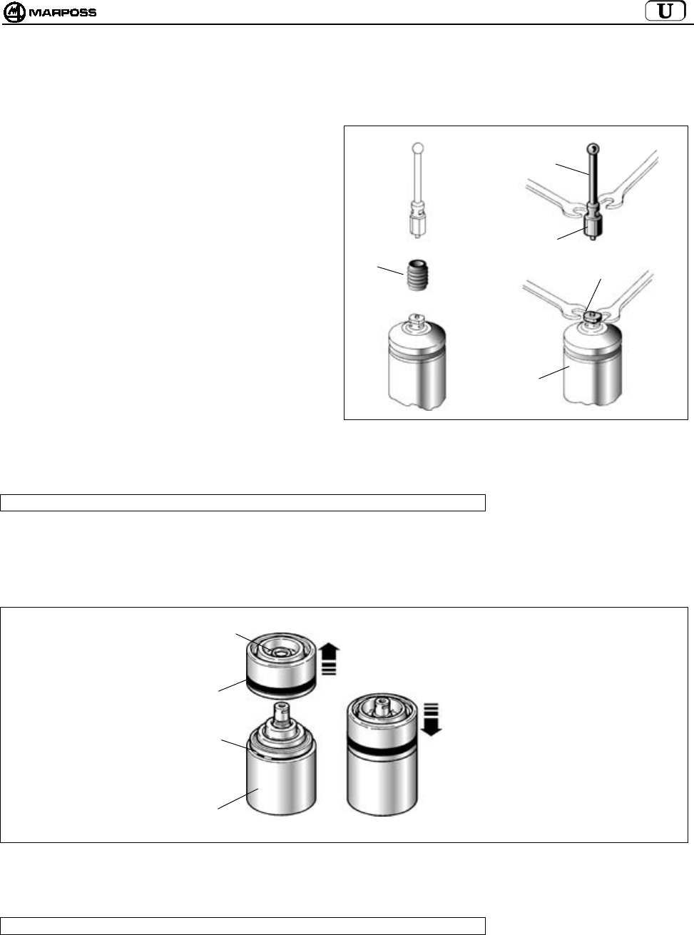
mida 89
15.2 Extraordinary maintenance
15.2.1 Substituting the crash protection pin/finger
If the finger is affected by accidental collisions, substitute the
crash protection pin and/or finger as follows.
1. Release the retainer (A), pulling it off the broken or bent
pin.
2. Release the finger (B) and the probe (C) from the
broken pin (D).
3. Remove the damaged finger from the probe (C).
Note: When performing these operations keep the
probe finger holder still with the wrench
supplied.
4. Then fit the new pin and finger (see "Fitting the probe
finger").
Figure 15-2
15.2.2 Substituting the outer seal
Note: this procedure is only valid for probes mounted on Standard transmitters
1- Remove the finger and the crash protection pin, if present.
2- Pull the front protection (B) with seal (C) off the probe body (A).
3- Check the condition of the front O-ring (D) and substitute it if necessary.
4- Insert the new front protection with seal until it snaps into place.
Figure 15-3
15.2.3 Substituting the probe/transmitter
Note: this procedure is only valid for probes mounted on Standard transmitters
1- Remove the finger and the crash protection pin, if present.
See "Fitting the probe finger".
2- Substitute the probe as indicated in "Fitting/removing the probe - transmitter".
A
D
B
C
D
D
B
C
A
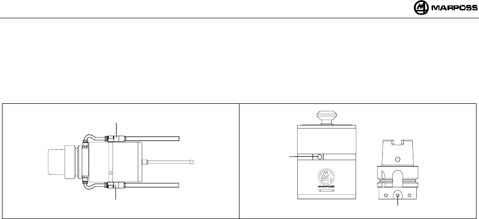
ENGLISH
E86N- Touch system with radio transmission
90
16. ACCESSORIES
16.1 Cleaning air support unit for Compact Transmitter
Fix the cleaning air support unit (A) in the holes (B) in the transmitter and taper (Figure 16-2). The pressure of the air supplied must be
≤6 bar (88.175 psi).
Figure 16-1 Figure 16-2
A
A
B
B

mida 91
17. SPARE PARTS LIST
CODE No. DESCRIPTION NOTES
1019108005 15 mm long crash protection pin
1019108003 Finger retainer
2915335018 Spare parts kit for T25/TL25/TT25 INCLUDES:
front protection complete with seal, front and rear O-rings, finger
retainer
2915340010 Spare parts kit for T36G INCLUDES:
probe front protection complete with seal, O-ring and finger
retainer
2915345007 Spare parts kit for T60G/TT60 INCLUDES:
probe front protection complete with seal, O-ring and finger
retainer
2915335013 Front protection for T25/TL25/TT25
2915340006 Front protection for T36
2915345012 Front protection for T60
3415335200 T25G probe
3415335201 T25S probe
3424306040 TL25G probe
3424306041 TL25S probe
3415340200 T36G probe
3415340201 T36S probe
3415345030 T60G probe
3415345050 T60S probe
3424310000 TT25 probe
3424310100 TT25H probe
3424451000 TT60 probe
2019923021 Transmitter fixing flange for T25/TL25/TT25 Complete with O-ring
2019923022 Transmitter fixing flange for T36 Complete with O-ring
2019923023 Transmitter fixing flange for T60/TT60 Complete with O-ring
2915335023 Extension for T25/TL25/TT25 L=23,5 mm
2915335100 Extension for T25/TL25/TT25 L=50 mm
2915335110 Extension for T25/TL25/TT25 L=100 mm
2915335120 Extension for T25/TL25/TT25 L=150 mm
2915340125 Extension for T36 L=50 mm
2915340126 Extension for T36 L=100 mm
2915340127 Extension for T36 L=150 mm
2915345040 Extension for T60/TT60 L=50 mm
2915345050 Extension for T60/TT60 L=100 mm
2915345060 Extension for T60/TT60 L=150 mm
3019917110 DIN 69871/A 40 taper with switch and adjusting flange
3019917120 DIN 69871/A 45 taper with switch and adjusting flange
3019917130 DIN 69871/A 50 taper with switch and adjusting flange
3019917140 CAT 40 taper with switch and adjusting flange
3019917150 CAT 45 taper with switch and adjusting flange
3019917160 CAT 50 taper with switch and adjusting flange
1502027040 Half-casing seal
1502027050 Half-casing seal (contacts side)
1502018260 Special screw for battery holder
4162100005 9V alkaline battery
4162100302 9V lithium battery
6180830500 Battery holder cover without contacts
2015340100 Wrenches kit INCLUDES:
wrenches for finger and Allen wrenches
1.5 – 2 – 2.5 – 3 – 4 mm
1320131000 Special wrench for T25/TL25/TT25
1320367000 Special wrench for T25/TL25/T36/T60/TT25/TT60 flange
2919917110 Standard transmitter adjusting flange
6871982001 E86N transmitter with radio activation
E86N STANDARD TRANSMITTER AND PROBES
6871982101 E86N transmitter with mechanical activation

ENGLISH
E86N- Touch system with radio transmission
92
CODE No. DESCRIPTION NOTES
1019108005 15 mm long crash protection pin
1019108003 Finger retainer
2015340100 Wrenches kit INCLUDES:
wrenches for finger and Allen wrenches
1.5 – 2 – 2.5 – 3 – 4 mm
4400000219 O-rings 2081 PARKER 2-19 (for battery cover)
4306400804 Hexagon socket head screws UNI-5931-12K M4X8 (for battery cover)
4162100004 1.5V alkaline battery
6180980085 Cleaning air unit
E86N-P COMPACT TRANSMITTER
6871983000 E86N-P transmitter with radio activation
6871980000 E86N antenna
6180985017 15 m long antenna connecting cable
ANTENNAS & EXTENSIONS
WITH CONNECTOR
6180985027 30 m long antenna connecting cable
INTERFACE
8304870000 E86N interface
ACCESSORIES
6739696319 Connection extension cable - E86N - CNC HEIDEN HAIN

mida 93
E86N
SCHALTMESSSYSTEM MIT FUNKÜBERTRAGUNG
Installations- und Bedienungsanleitung
DEUTSCH
E86N- Schaltmesssystem mit Funkübertragung
94
Das Wegwerfen und die Entsorgung dieses Produkts als allgemeiner Hausmüll und
jedes seiner mechanisch davon trennbaren Teile ist verboten (Europäische Richtlinien
2002/95/EG und 2002/96/EG und weitere bzw. deren Umsetzung in nationales Recht).
Die gesetzlichen Bestimmungen gelten nur für die mit dem entsprechenden Symbol
(durchgestrichene Mülltonne auf Rädern, siehe oben) gekennzeichneten Produkte,
die ab dem 13. August 2005 auf den Markt gebracht wurden.
Für die Entsorgung (Wiederverwendung, Verwertung, Verschrottung) wenden Sie sich an ein hierfür
berechtigtes Unternehmen bzw. setzen Sie sich für weitere Informationen mit Ihrer lokalen
Abfallentsorgungszentrale oder mit der nächsten Marposs-Niederlassung in Verbindung.
Dieses Produkt kann für Menschen und Umwelt schädliche Stoffe und Teile enthalten, die eine
fachgerechte Entsorgung notwendig machen.
Die rechtswidrige Entsorgung dieses Produkts wird bestraft.
2002/95/CE
2002/96/CE
MARPOSS S.p.A. ist nicht zur Mitteilung nachträglicher Änderungen am Produkt verpflichtet.
Die Beschreibungen in diesem Handbuch rechtfertigen keine Eingriffe durch unbefugtes Personal.
Bei Feststellung solcher Eingriffe verfällt der Garantieanspruch.

mida 95
Inhaltsverzeichnis
1. VORSCHRIFTEN UND ALLGEMEINE HINWEISE ............................................................................................................................... 97
2. BAUTEILE DES SYSTEMS ................................................................................................................................................................... 98
3. AUFBAU UND FUNKTIONSWEISE ...................................................................................................................................................... 99
4. ANWENDUNGSHINWEISE ................................................................................................................................................................. 100
5. SCHALTMESSKÖPFE / KOMPAKTSENDERMODUL E86N-P.......................................................................................................... 101
6. FUNKÜBERTRAGUNG ....................................................................................................................................................................... 102
6.1 Beschreibung ............................................................................................................................................................................... 102
6.1.1 Anwendungsabstand für mehrere Systeme .......................................................................................................................... 102
6.2 Aktivierung der Übertragung ........................................................................................................................................................ 103
6.2.1 Funkaktivierung ..................................................................................................................................................................... 103
6.2.2 Schalteraktivierung ................................................................................................................................................................ 103
6.3 Deaktivierung der Übertragung.................................................................................................................................................... 103
6.3.1 Sendermodul mit Funkaktivierung ......................................................................................................................................... 103
6.3.2 Sendermodul mit Schalteraktivierung.................................................................................................................................... 103
7. SENDERMODUL E86N........................................................................................................................................................................ 104
7.1 Beschreibung ............................................................................................................................................................................... 104
7.2 Batterielebensdauer und Anzeigen auf der Schnittstelleneinheit................................................................................................. 105
7.3 Abmessungen des Sendermoduls mit den Schaltmessköpfen.................................................................................................... 106
7.3.1 Standardsendermodul mit Standardflansch .......................................................................................................................... 106
7.3.2 Standardsendermodul mit Regulierflansch............................................................................................................................ 107
7.4 Abmessungen des Kompaktsendermoduls ................................................................................................................................. 108
7.4.1 Kompaktsendermodul E86N-P .............................................................................................................................................. 108
7.4.2 Kompaktsendermodul E86N-P ohne konischen Zapfen........................................................................................................ 108
8. EMPFÄNGERMODUL.......................................................................................................................................................................... 109
8.1 Empfängermodul mit steckbarem Anschlusskabel ...................................................................................................................... 109
8.2 Remote Display Modus................................................................................................................................................................ 109
8.3 Anschluss des Empfängermoduls................................................................................................................................................ 109
8.4 Montage des Empfängermoduls .................................................................................................................................................. 110
9. SCHNITTSTELLENEINHEIT E86N...................................................................................................................................................... 111
Fronttafel der Schnittstelleneinheit........................................................................................................................................................ 111
9.2 Abmessungen der Schnittstelleneinheit....................................................................................................................................... 112
9.3 Technische Merkmale der Schnittstelleneinheit E86N................................................................................................................. 112
9.4 Anschlussplan Schnittstelleneinheit............................................................................................................................................. 113
9.4.1 Wahl des Identifikationscodes ............................................................................................................................................... 113
Überblick Ein-/Ausgänge Schnittstelleneinheit E86N............................................................................................................................ 114
10. PROGRAMMIERUNG DES SYSTEMS ............................................................................................................................................. 115
10.1 Programmierung der Schnittstelleneinheit (Interface).................................................................................................................. 116
10.2 Programmierung des Sendermoduls mit Schaltmesskopf (Probe) .............................................................................................. 119
10.3 Programmierung des Sendermoduls im Recovery-Modus .......................................................................................................... 121
10.4 Belegungsanalyse des elektromagnetischen Spektrums („SNIFFER“-Funktion) ........................................................................ 122
10.4.1 Scanning................................................................................................................................................................................ 123
10.4.2 Anzeige der Ergebnisse ........................................................................................................................................................ 123
11. ANBAU DER SCHALTMESSKÖPFE AM STANDARDSENDERMODUL ........................................................................................ 124
11.1 Montage des Schaltmesskopfs am Standardsendermodul.......................................................................................................... 124
11.2 Einbau der Verlängerungen für Schaltmessköpfe (Option) ......................................................................................................... 125
12. MONTAGE DES SENDERMODULS ................................................................................................................................................. 126
12.1 Montage des Sendermoduls mit Standardflansch ....................................................................................................................... 126
12.2 Montage des Sendermoduls mit Regulierflansch ........................................................................................................................ 127
12.3 Montage des Kompaktsendermoduls auf dem Kegel .................................................................................................................. 129
12.3.1 Befestigung des Kompaktsendermoduls am Kegel (Bearbeitung des Kegels) ..................................................................... 129
12.3.2 Befestigung des Kompaktsendermoduls ohne konischen Zapfen am Kegel (Bearbeitung des Kegels)............................... 129
13. MONTAGE DES TASTERARMS....................................................................................................................................................... 130
14. DIAGNOSE......................................................................................................................................................................................... 131
14.1 Fehlermeldungen ......................................................................................................................................................................... 131
14.2 Led Anzeigen ............................................................................................................................................................................... 131
15. WARTUNG ......................................................................................................................................................................................... 132
15.1 Laufende Instandhaltung ............................................................................................................................................................. 132
15.1.1 Reinigung und Kontrollen ...................................................................................................................................................... 132
15.1.2 Einsetzen/Auswechseln der Sendermodulbatterie ................................................................................................................ 132

DEUTSCH
E86N- Schaltmesssystem mit Funkübertragung
96
15.2 Außerplanmäßige Wartung .......................................................................................................................................................... 133
15.2.1 Auswechseln des Sollbruchstücks /Tasterarms .................................................................................................................... 133
15.2.2 Auswechseln der Messkopfkappe ......................................................................................................................................... 133
15.2.3 Auswechseln des Schaltmesskopfs/Sendermoduls .............................................................................................................. 133
16. ZUBEHÖRTEILE ................................................................................................................................................................................ 134
16.1 Reinigungslufteinheit für Kompaktsendermodul...........................................................................................................................134
17. ERSATZTEILLISTE............................................................................................................................................................................ 135
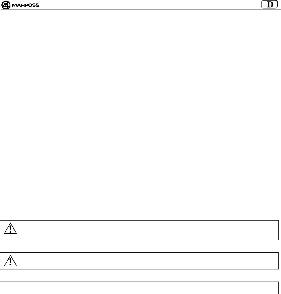
mida 97
1. VORSCHRIFTEN UND ALLGEMEINE HINWEISE
VORWORT
Diese Betriebsanleitung liefert alle Informationen, die für die Kenntnis und die korrekte Anwendung Ihres MARPOSS Geräts
erforderlich sind.
Die Beschreibungen in diesem Handbuch sind an folgendes Personal gerichtet:
• Personal von MARPOSS oder des Kunden, das die Installation des Geräts vorzunehmen hat.
• Technisches Personal des Kunden, das direkt mit dem MARPOSS Gerät arbeiten wird.
• Technisches Personal des Kunden, das für die Wartung der Produktionslinie zuständig ist, in der das MARPOSS Gerät installiert
wird.
ALLE RECHTE VORBEHALTEN. DIESES HANDBUCH IST NUR FÜR DEN FIRMENINTERNEN GEBRAUCH SEITENS DES KUNDEN BESTIMMT. JEGLICHE
ANDERWEITIGE VERWENDUNG IST UNTERSAGT.
ABNAHME UND GARANTIE
Auf Materialfehler wird eine Garantie mit folgenden Einschränkungen gewährt:
• GARANTIEDAUER: Die Garantieleistung ist eine Materialgarantie und erstreckt sich auf das Produkt und alle im vereinbarten
Garantiezeitraum erfolgten Reparaturen.
• GARANTIEGEGENSTAND: Die Garantie gilt für das Produkt und seine mit Seriennummer oder einer anderen MARPOSS
Kennnummer gekennzeichneten Bestandteile.
Die o.g. Garantiebedingungen sind gültig, soweit keine anderslautenden Vereinbarungen zwischen MARPOSS und dem Kunden
getroffen wurden.
ALLGEMEINE SICHERHEITSVORSCHRIFTEN
Das Gerät wurde gemäß CEI EN60950 gebaut.
VERWENDETE KONVENTIONEN UND SYMBOLE
Bei der Abfassung des Handbuchs wurden einige typographische Hervorhebungen verwendet.
Im Einzelnen definierte man zwei Arten von Warnhinweisen:
Warnung:
Dieses Zeichen weist auf die Möglichkeit einer Beschädigung der elektronischen Einheit und aller daran angeschlossenen
Vorrichtungen oder auf die Gefahr eines Datenverlusts hin.
Achtung:
Dieses Zeichen bedeutet eine Gefahrensituation für den Bediener oder den Techniker.
Besonders wichtige Angaben, die zum besseren Verständnis und zur leichteren Anwendung des Systems beitragen, sind eingerahmt
und durch “Hinweis“ in Fettdruck gekennzeichnet.

DEUTSCH
E86N- Schaltmesssystem mit Funkübertragung
98
2. BAUTEILE DES SYSTEMS
A1 - Schaltmesskopf mit Sendermodul E86N (Standard)
A2 - Sendermodul E86N-P mit eingebautem Schaltmesskopf (Kompakt)
B - Sollbruchstück (optional)
C - Sicherungshülse (optional)
D - Tasterrm
E - Empfängermodul
F - Schnittstelleneinheit E86N
G - Zwei Maulschlüssel CH 5 - 5.5 und ein Satz Sechskantschlüssel
H - Ein Spezialhakenschlüssel für Schaltmesskopf
I - Verlängerungen für Schaltmessköpfe (optional)
L - Zusatzempfängermodul (optional)
Abbildung 2-1. Bauteile des Systems
A1
B
C
D
E
G
F
H
I
L
A2

mida 99
3. AUFBAU UND FUNKTIONSWEISE
Das System dient zur Bestimmung von Raumpunkten, welche von der CNC-Steuerung der Bearbeitungsmaschine für die gewünschten
Messungen verarbeitet werden. Diese Punkte werden über einen Schaltmesskopf, einen hochpräzisen multidirektionalen Mikroschalter,
aufgenommen. Die entsprechenden Signale werden durch das Funkübertragungssystem, bestehend aus einem Sendermodul und
einem Empfängermodul über die Schnittstelleneinheit an die CNC- Steuerung übertragen. Im Meßzyklus wird die an einem Steilkegel
montierte Schaltmeßkopf-/ Sendereinheit aus dem Werkzeugmagazin in die Werkzeugspindel geladen. Das System ist einfach zu
bedienen und wurde für den Einsatz im rauhesten Werkstattbetrieb entwickelt. Es wird auf Bearbeitungszentren und Fräsmaschinen
verwendet und dient zur: Erkennung, Positionierung und Messung des zu bearbeitenden Werkstücks sowie zur Messung des
bearbeiteten Werkstücks.
Die typische Applikation des Systems besteht aus:
A - Zu messendes Werkstück E - Spindel Werkzeugmaschine
B - Tasterarm F - Empfängermodul E86N
C - Schaltmesskopf G - Schnittstelleneinheit E86N
D - Sendermodul E86N H - CNC-Steuerung der Werkzeugmaschine
Abbildung 3-1.Aufbau und Funktionsweise.
BA
C
D
E
F
G
H

DEUTSCH
E86N- Schaltmesssystem mit Funkübertragung
100
4. ANWENDUNGSHINWEISE
Das Messsystem ist multidirektional in der Hemisphäre x/y/+z.
Berührt der Tasterarm des Messkopfes die Werkstückoberfläche, wird ein Schaltsignal erzeugt, welches an die CNC-Steuerung
übertragen wird. Diese registriert den Kontaktpunkt und stoppt die Maschinenbewegung. Um eine gute Wiederholbarkeit zu
gewährleisten, sollten die Messzyklen bei konstanter Antastgeschwindigkeit erfolgen.
Die gewählte Messgeschwindigkeit muss das Anhalten der Maschinenachse innerhalb der Grenzen des Überlaufs des
verwendeten Schaltmesskopfs zulassen.
Vor Verwendung des Schaltmesskopfs muss der systematische Messfehler des aus Schaltmesskopf, Werkzeugmaschine und
CNC-Steuerung bestehenden Systems durch eine Kalibrierung ausgeglichen werden. Der systematische Fehler ist für jede
Messrichtung charakteristisch und wiederholbar, weshalb die Kalibrierung in jeder Richtung erfolgen muss, in der gemessen
wird. Zur Kalibrierung des Systems empfiehlt es sich, Punkte mit bekanntem Wert (R) in der Maschine zu ermitteln und die
Differenz zwischen diesen und den gemessenen Werten (R+K1) zu berechnen. Diese Differenz (K1) muss in die
Werkzeugkorrekturparameter der CNC-Steuerung eingegeben und immer dann abgerufen werden, wenn eine Messung in die
gleiche Richtung erfolgt.
K1
Abbildung 4-1. Anwendung
X/Y
Z
X/Y
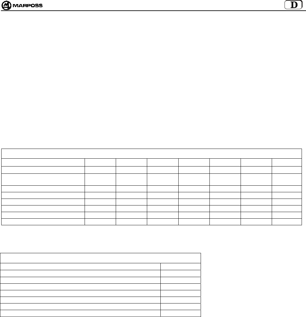
mida 101
5. SCHALTMESSKÖPFE / KOMPAKTSENDERMODUL E86N-P
Der Schaltmesskopf ist ein multidirektionaler Präzisionsmikroschalter, der in den Applikationen auf CNC-Werkzeugmaschinen zur
Kontrolle und Messung von Werkzeugen und Werkstücken verwendet wird.
Es sind verschiedene Modelle multidirektionaler Schaltmessköpfe in der Hemisphäre x/y/+z erhältlich.
Für einige Modelle gibt es zwei verschiedene Versionen je nach der Art der Messkopfkappe:
• “Version G” mit gewebeverstärkter Gummidichtung für einen besseren Schutz gegen die Kühlflüssigkeit.
• “Version S” mit Metallschild zum Schutz gegen heiße Spänen.
Zur optimalen Lösung der spezifischen Anforderungen auf unterschiedlichen Werkzeugmaschinen stehen folgende Schaltmessköpfe
zur Auswahl:
Schaltmesskopf T25G / T25S
Schaltmesskopf TL25G / TL25S
Schaltmesskopf T36G / T36S
Schaltmesskopf T60G / T60S
Schaltmesskopf TT25 (nur in Version G)
Schaltmesskopf TT25H (nur in Version G)
Schaltmesskopf TT60 (nur in Version G)
Tabelle 5-1. Technische Merkmale der Schaltmessköpfe
Typ T25 TL25 T36 T60 TT25 TT25H TT60
Achsen ±X, ±, Y+Z±X, ±Y, +Z±X, ±Y, +Z±X, ±Y,+Z±X, ±Y,+Z±X, ±Y,+Z±X, ±Y,+Z
Undirektionale Wiederholbarkeit (2 σ)
mit Geschwindigkeit bis zu 600 mm/min
0,5 µm0,5 µm0,5 µm1 µm1 µm2 µm1 µm
Messkraft in der X-Y Ebene 2 N 0,9 N 2,6 N 2,8 N 0,5-0,9 N 0,9-1,75 N 0,7-1,2 N
Messkraft in Richtung Z12 N 5,5 N 12 N 12 N 5,8 N 10,8 N 5,8 N
Überlauf in der X-Y Ebene 11,2 mm 11,2 mm 14,4 mm 22 mm 11,6 mm 11,6 mm 19 mm
Überlauf in Richtung Z4 mm 4 mm 4,2 mm 6,4 mm 4 mm 4 mm 6,4 mm
Standardtaster L= 35 mm 35 mm 40 mm 50 mm 35 mm 35 mm 50 mm
Schutzart nach IEC IP67 IP67 IP67 IP67 IP67 IP67 IP67
Im Unterschied zum Standardsendermodul, auf den jeder der in Tabelle 5-1 enthaltenen Schaltmessköpfe montiert werden kann, hat
der Kompaktsendermodul E86N-P den Schaltmesskopf bereits eingebaut. Er besitzt folgende technische Merkmale:
Tabelle 5-2. Technische Merkmale des Kompaktsendermoduls
Achsen ±X, ±, Y+Z
Unidirektionale Wiederholbarkeit (2 σ) mit Geschwindigkeit bis zu 600 mm/min 0,5 µm
Messkraft in der X-Y-Ebene 2 N
Messkraft in Richtung Z 12 N
Überlauf in der X-Y-Ebene 11,2 mm
Überlauf in Richtung Z4 mm
Standardtasterarmlänge L= 35 mm
Schutzart nach IEC-Norm IP68
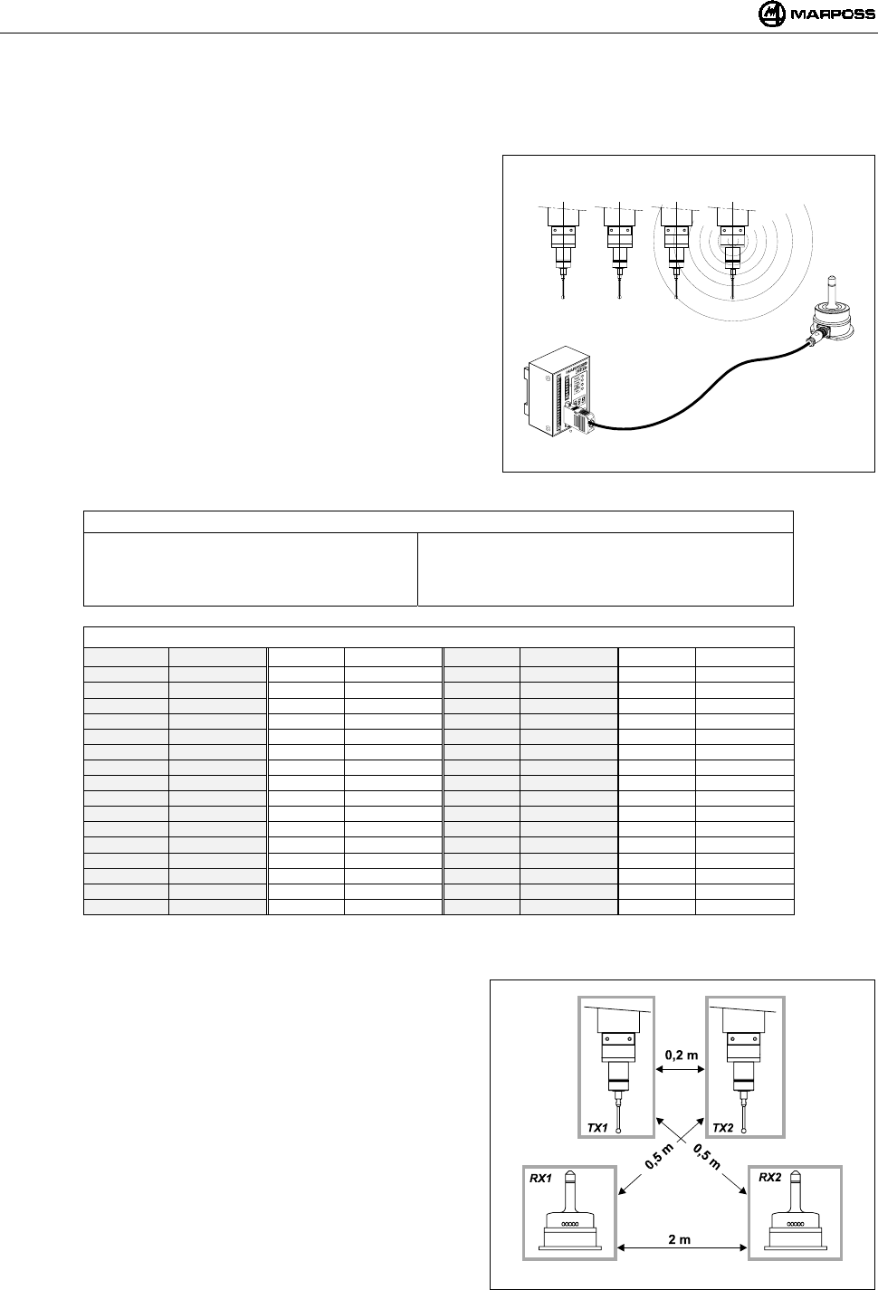
DEUTSCH
E86N- Schaltmesssystem mit Funkübertragung
102
6. FUNKÜBERTRAGUNG
6.1 Beschreibung
Das Funkübertragungssystem besteht aus drei Elementen:
Sendermodul: Sendet die Informationen, die der CNC-Steuerung zur
Verarbeitung der Messung dienen.
Empfängermodul: Empfängt das Signal des Sendermoduls und leitet
es an die Schnittstelleneinheit E86N weiter.
Schnittstelleneinheit: Verarbeitet die Signale und wandelt sie in eine
von der CNC-Steuerung benutzbare Form um.
Das System E86N ermöglicht die Programmierung von 64 verschiedenen
Übertragungskanälen über die Tastatur auf der Schnittstelleneinheit (siehe
Kapitel 10 "PROGRAMMIERUNG DES SYSTEMS” auf S. 115).
Zur Erweiterung des Übertragungsbereichs und der Zuverlässigkeit der
Funkübertragung besteht die Möglichkeit, zwei Empfängermodule an die
Schnittstelleneinheit E86N anzuschließen.
Das System ermöglicht den Einsatz von bis zu maximal 4 Sendermodulen
auf der gleichen Werkzeugmaschine (Abbildung 6-1), die auf dem
gleichen Kanal arbeiten und jeweils einzeln über unterschiedliche
Identifikationscodes aktivierbar sind (siehe Punkt 10.2 “Programmierung
des Sendermoduls mit Schaltmesskopf (Probe)" auf S. 119.
Abbildung 6-1. Funkübertragungssystem.
Tabelle 6-1. Technische Merkmale.
-Übertragungsabstand : 15 m -Aktivierungsleistung : <10 mW
-Übertragungsleistung : <1mW -Anzahl Übertragungskanäle : 64
-Abstand für Aktivierung, Deaktivierung
und Programmierung
: 5 m -Übertragungsfrequenz :433,075÷434,775 Mhz
Tabelle 6-2. Übertragungsfrequenzen.
KANÄLE FREQUENZ KANÄLE FREQUENZ KANÄLE FREQUENZ KANÄLE FREQUENZ
1 433,075 17 433,475 33 434,000 49 434,400
2 433,100 18 433,500 34 434,025 50 434,425
3 433,125 19 433,525 35 434,050 51 434,450
4 433,150 20 433,550 36 434,075 52 434,475
5 433,175 21 433,575 37 434,100 53 434,500
6 433,200 22 433,600 38 434,125 54 434,525
7 433,225 23 433,625 39 434,150 55 434,550
8 433,250 24 433,650 40 434,175 56 434,575
9 433,275 25 433,675 41 434,200 57 434,600
10 433,300 26 433,700 42 434,225 58 434,625
11 433,325 26 433,725 43 434,250 59 434,650
12 433,350 28 433,750 44 434,275 60 434,675
13 433,375 29 433,775 45 434,300 61 434,700
14 433,400 30 433,800 46 434,325 62 434,725
15 433,425 31 433,825 47 434,350 63 434,750
16 433,450 32 433,850 48 434,375 64 434,775
6.1.1 Anwendungsabstand für mehrere Systeme
Zur Vermeidung einer Störung zwischen nebeneinander platzierten
Systemen müssen folgende Abstände eingehalten werden:
Mindestens 2 m zwischen den Empfängermodulen der Systeme,
unabhängig davon, ob benachbarte Kanäle (z.B. CH5 und CH6)
verwendet werden oder nicht.
Mindestens 0,2 m zwischen den Sendermodulen der Systeme,
unabhängig davon, ob benachbarte Kanäle verwendet werden oder
nicht.
Mindestens 0,5 m zwischen dem Sendermodul eines Systems und
dem Empfängermodul des anderen, die auf benachbarten Kanälen
arbeiten.
HINWEIS: Bei Verwendung von 2 Systemen auf ein und derselben
Maschine (z.B. Bearbeitungszentren mit Doppelspindel), ist
neben der Einhaltung der den in Abbildung 6-2 angegebenen
Abstände die Verwendung von zwei NICHT benachbarten
Kanälen und der Identifikationscodes “A” und “D” erforderlich.
Der Abstand zwischen Systemen, die auf dem gleichen Kanal
arbeiten, muss größer als 100 m sein.
Abbildung 6-2. Abstand bei Verwendung von mehreren
Systemen
ABCD
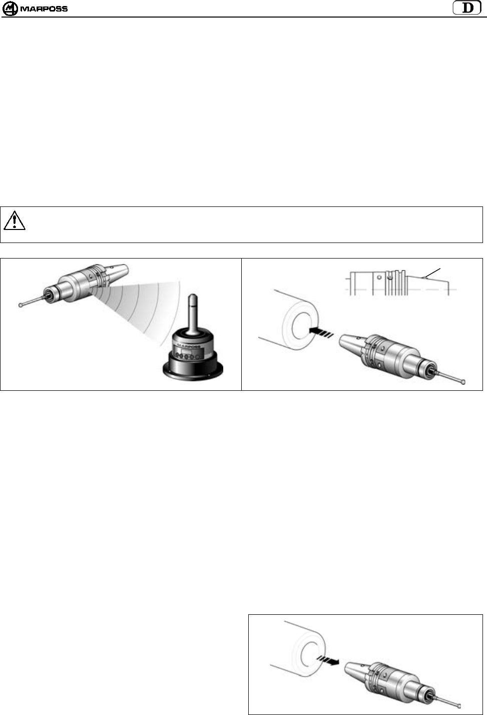
mida 103
6.2 Aktivierung der Übertragung
Der Sendermodul befindet sich normalerweise im Wartezustand (Standby). Die Übertragung kann, je nach Sendermodulversion, auf
zwei Arten aktiviert werden:
•Funkaktivierung
•Schalteraktivierung (nur beim Standardsendermodul)
6.2.1 Funkaktivierung
Die Aktivierung des Systems erfolgt nach Sendung eines Funksignals von dem Empfängermodul an den Sendermodul. Der
Systemaktivierungsbefehl (START) wird auf zwei Arten von der Schnittstelleneinheit erzeugt:
durch einen Maschinenbefehl auf dem Eingang START/STOP (M-Code).
über Tastatur durch Drücken der Taste <select> (mindestens 2 Sekunden lang)
6.2.2 Schalteraktivierung
Am Werkzeughaltekegel befindet sich ein Mikroschalter (H). Das Einsetzen des Steilkegels in die Spindel bewirkt die
Übertragungsaktivierung.
Warnung:
Wenn der Sendermodul wieder in das Werkzeugmagazin zurückplatziert wird, sich vergewissern, dass der
Aktivierungsmikroschalter nicht betätigt wird.
Abbildung 6-3. Funkaktivierung. Abbildung 6-4. Schalteraktivierung
6.3 Deaktivierung der Übertragung
Die Deaktivierung der Übertragung kann, je nach der Sendermodulversion, auf zwei Arten erfolgen.
6.3.1 Sendermodul mit Funkaktivierung
FUNKDEAKTIVIERUNG:
1. Maschinenlogik
Die Deaktivierung erfolgt durch einen Maschinenbefehl auf dem Eingang START/STOP (M-Code).
2. Tastatur
Die Deaktivierung erfolgt durch Drücken der Taste <select> (mindestens 2 Sekunden lang).
AUTOMATISCHE DEAKTIVIERUNG
Die automatische Deaktivierung erfolgt bei Ablauf der auf dem Timer des Sendermoduls eingestellten Zeit
(siehe Punkt 10.2 “Programmierung des Sendermoduls mit Schaltmesskopf (Probe)" auf S. 119).
6.3.2 Sendermodul mit Schalteraktivierung
SCHALTERDEAKTIVIERUNG
Die Deaktivierung erfolgt, wenn der Sendermodul aus der
Spindel gezogen wird.
AUTOMATISCHE DEAKTIVIERUNG
Die Deaktivierung erfolgt bei Ablauf der auf dem Timer
des Sendermoduls eingestellten Zeit. (siehe Punkt 10.2
“Programmierung des Sendermoduls mit Schaltmesskopf
(Probe)" auf S. 119).
Abbildung 6-5. Beispiel einer Schalterdeaktivierung.
H
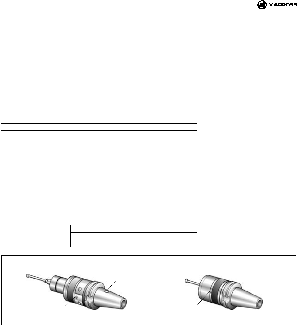
DEUTSCH
E86N- Schaltmesssystem mit Funkübertragung
104
7. SENDERMODUL E86N
7.1 Beschreibung
Es stehen zwei Sendermodultypen zur Wahl:
• STANDARDSENDERMODUL
auf dem die verschiedenen Typen von Schaltmessköpfen durch entsprechende Adapterflansche befestigt werden
• KOMPAKTSENDERMODUL
Der Schaltmesskopf T25 ist im Sendermodul eingebaut.
Der Sendermodul überträgt dem Empfängermodul folgende Informationen, die die CNC-Steuerung zur Verarbeitung der Messung
benötigt:
• Status des Schaltmesskopfs: Schaltmesskopf mit Tasterarm in Ruhestellung/ Schaltmesskopf mit ausgelenktem Tasterarm
• Status der Batterien: geladen oder schwach bzw. leer
Eine grüne LED (L) zeigt den Status des Schaltmesskopfs, der Batterien und der Übertragung an:
LED dauerd leuchtend = Schaltmesskopf mit ausgelenktem Tasterarm
1 Impuls alle 2s = Übertragung aktiviert
2 Impulse alle 2s = Batterien schwach
Die Standardsendermodule sind wiederum unterteilt in:
• SENDERMODULE MIT FUNKAKTIVIERUNG:
Die Übertragung wird durch ein vom Empfängermodul gesendetes Signal aktiviert.
• SENDERMODULE MIT SCHALTERAKTIVIERUNG:
Die Übertragung wird per Mikroschalter (H) am Werkzeughaltekegel aktiviert.
Beim Sendermodul mit Funkaktivierung ist kein Eingang für Mikroschalter vorhanden.
ACHTUNG: Die Schalteraktivierung ist nur auf Standardsendermodulen und nicht auf Kompaktsendermodulen vorgesehen.
Sendermodulprogrammierung siehe Punkt 10.2 “Programmierung des Sendermoduls mit Schaltmesskopf (Probe)" auf S. 119.
Tabelle 7-1. Technische Merkmale
Versorgung: : Batterien 9V (Standardsendermodul)
: 6 Batterien 1,5 V (Kompaktsendermodul)
Übertragungsabstand : 15m
Abbildung 7-1. Sendermodul
H
Standardsendermodul Kompaktsendermodul
LL
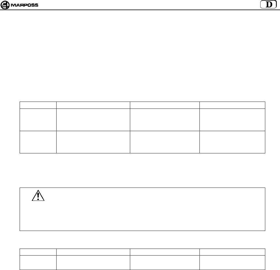
mida 105
7.2 Batterielebensdauer und Anzeigen auf der Schnittstelleneinheit
Der Ladezustand der Batterien des Sendermoduls kann auf der Schnittstelleneinheit angezeigt werden, und zwar sowohl durch die
Leds (Led Low Battery oder Led Error) als auch am Display. Bei eingeschaltetem System erscheint durch Drücken der Taste <select>
links der Identifikationscode und rechts das Ladeniveau (“7” max. Wert und “0” Batterie vollkommen leer). Im Einzelnen bedeutet das:
• Die Led “Low battery” schaltet sich ein, wenn am Display Niveau “3” angezeigt wird
• Die Led “Error” schaltet sich ein, wenn am Display Niveau “0” angezeigt wird.
Der am Display erscheinende Ladewert bleibt bis zu nachfolgenden Aktivierung gespeichert.
Die Lebensdauer der Batterien hängt von der Benutzungsdauer des Sendermoduls und des verwendeten Batterietyps ab. In der Tabelle
sind die Werte für die Lebensdauer angegeben, die durch den Batterietyp und den Dauer- oder Standby-Betrieb des Sendermoduls
bedingt sind:
• Standardsendermodul
BATTERIETYP EMPFOHLENE BATTERIE DAUERBETRIEB STANDBY-BETRIEB
Alkali DURACELL MN1604
DURACELL PC1604 PROCELL
ENERGIZER X22
ENERGIZER 522
150 Stunden 170 Tage
Lithium ENERGIZER L522
ULTRALIFE U9VL
DURACELL PL1604
SONNENSCHEIN SLM9-J
320 Stunden 380 Tage
Hinweis: In der Packung des Sendermoduls befindet sich eine Batterie. Sie ist vor der Installation des
Systems in den Sendermodul einzusetzen (siehe Punkt 15.1.2 “Einsetzen/Auswechseln der
Sendermodulbatterie” auf S. 132).
Warnung:
SENDERMODUL MIT SCHALTERAKTIVIERUNG
Sicherstellen, dass der Sitz des Steilkegels im Werkzeugmagazin so geformt ist, dass der Schalter
(H) nicht betätigt werden kann.
LITHIUMBATTERIEN: Lithiumbatterien können explodieren, wenn sie nicht korrekt ausgetauscht
werden. Nur den gleichen oder einen ähnlichen Batterietyp (siehe Tabelle) einsetzen. Alte Batterien
nach den einschlägigen Bestimmungen entsorgen.
• Kompaktsendermodul
BATTERIETYP EMPFOHLENE BATTERIE DAUERBETRIEB STANDBY-BETRIEB
DURACELL MN9100
Alkali
ENERGIZER E90 230 Stunden 250 Tage
Hinweis: Die Batterien befinden sich in der Packung des Sendermoduls.
Sie sind vor der Installation im Sendermodul einzusetzen (siehe Punkt 15.1.2 “Einsetzen/Auswechseln
der Sendermodulbatterie” auf S. 132).

DEUTSCH
E86N- Schaltmesssystem mit Funkübertragung
106
7.3 Abmessungen des Sendermoduls mit den Schaltmessköpfen
7.3.1 Standardsendermodul mit Standardflansch
Abbildung 7-2. Abmessungen des Sendermoduls mit Standardflansch
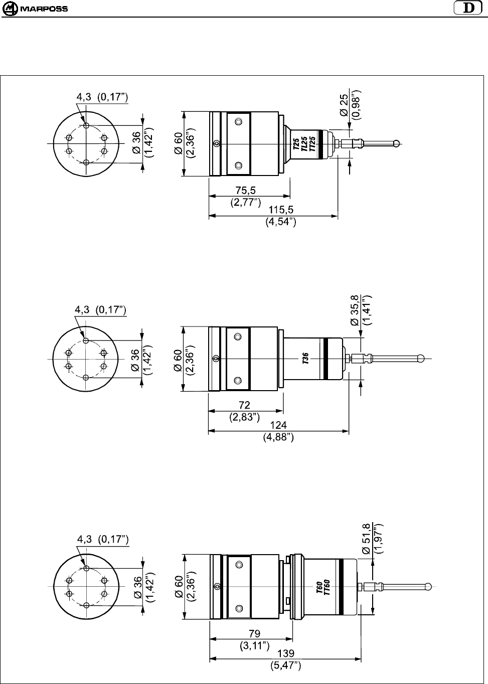
mida 107
7.3.2 Standardsendermodul mit Regulierflansch
Abbildung 7-3. Abmessungen des Sendermoduls mit Regulierflansch.
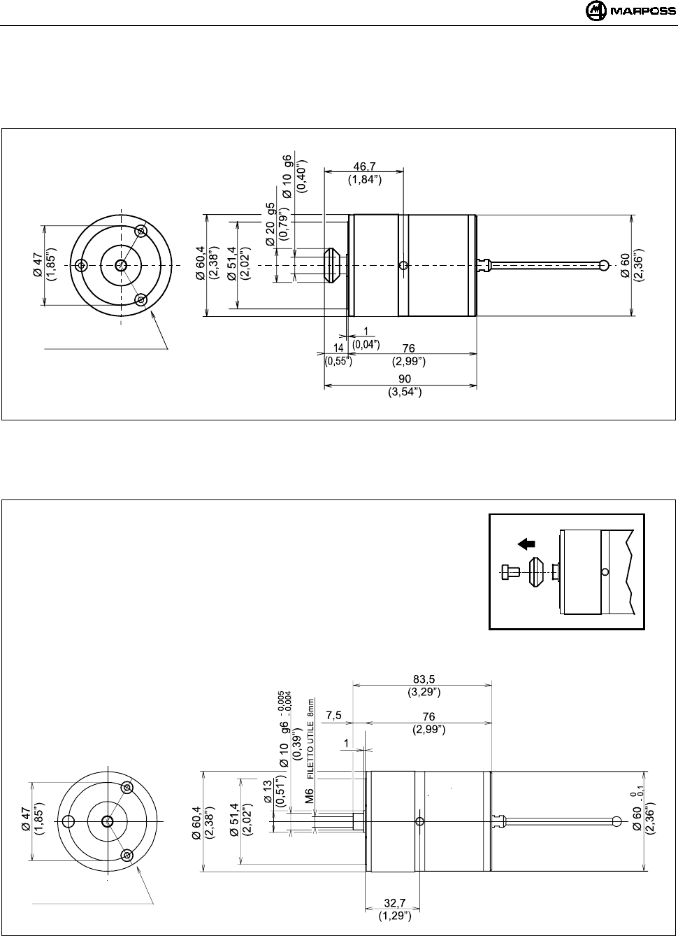
DEUTSCH
E86N- Schaltmesssystem mit Funkübertragung
108
7.4 Abmessungen des Kompaktsendermoduls
7.4.1 Kompaktsendermodul E86N-P
Abbildung 7-4
7.4.2 Kompaktsendermodul E86N-P ohne konischen Zapfen
Abbildung 7-5
NR.3 SCHR. M4X6
NR.3 SCHR. M4X6
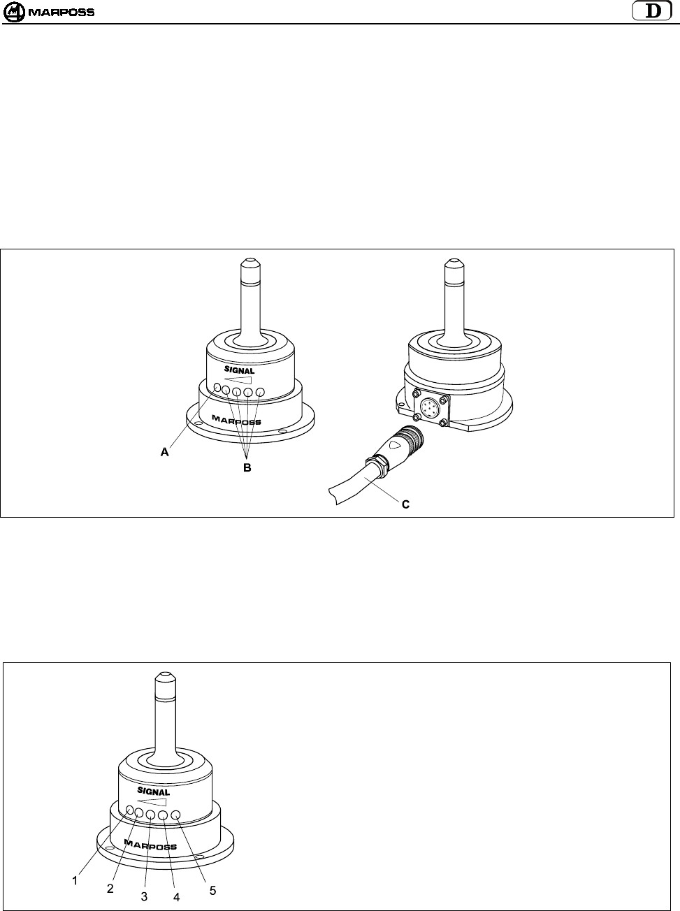
mida 109
8. EMPFÄNGERMODUL
8.1 Empfängermodul mit steckbarem Anschlusskabel
Der Empfängermodul empfängt die Daten vom Sendermodul und übermittelt sie an die Schnittstelleneinheit E86N. Er ist mit
Stecksockel für das Anschlusskabel versehen, das zur Schnittstelleneinheit führt.
Auf der Vorderseite des Empfängermodul befinden sich:
A- eine rote LED, deren Leuchten bedeutet, dass die Übertragung nicht stattfindet oder dass das Signal des Sendermoduls nicht
empfangen wurde;
B- eine gelbe LED und drei grüne LED’s, die die Intensität des empfangenen Signals anzeigen; die Einschaltung der LED’s
erleichtert bei der Installation die optimale Ausrichtung des Empfängermodul;
C- ein abgeschirmtes Kabel mit Steckverbinder (15m oder 30m lang) für den Anschluss an die Schnittstelleneinheit E86N.
Abbildung 8-1: Empfängermodul mit steckbarem Anschlusskabel.
8.2 Remote Display Modus
Die Leds auf dem Empfängermodul können außerdem als Ferndisplay der Schnittstelleneinheit funktionieren, wenn bei der
Programmierung der Schnittstelleneinheit der Datenwert “rd” (remote display) entsprechend eingegeben wird (siehe Punkt 10.1
Programmierung der Schnittstelleneinheit (Interface) neinheit” auf S. 116).
In diesem Fall haben die Leds folgende Bedeutung:
1 -
2 -
3 -
4 -
5 -
Led ROT = ERROR
Led GELB = LOW BAT
Led GRÜN = immer aus
Led GRÜN = PROBE
Led GRÜN = POWER
Abbildung 8-2. Betriebsart des Empfängermodul als Fernanzeige der Schnittstelleneinheit
8.3 Anschluss des Empfängermoduls
Der Empfängermodul muss an der Klemmleiste der Schnittstelleneinheit E86N (siehe Schaltplan in Punkt 9.4 "Anschlussplan
Schnittstelleneinheit” auf S. 113) angeschlossen werden.
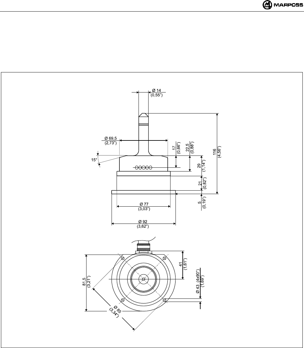
DEUTSCH
E86N- Schaltmesssystem mit Funkübertragung
110
8.4 Montage des Empfängermoduls
• Der Empfängermodul kann provisorisch mit der magnetischen Basis befestigt werden, um die geeignetste Position zu ermitteln
und um zu prüfen, ob das vom Sendermodul abgegebene Signal auch wirklich während der Bewegungen des Tastsystems
empfangen wird.
• Zur definitiven Montage mit den zum Lieferumfang gehörenden Schrauben anschrauben.
Abbildung 8-3
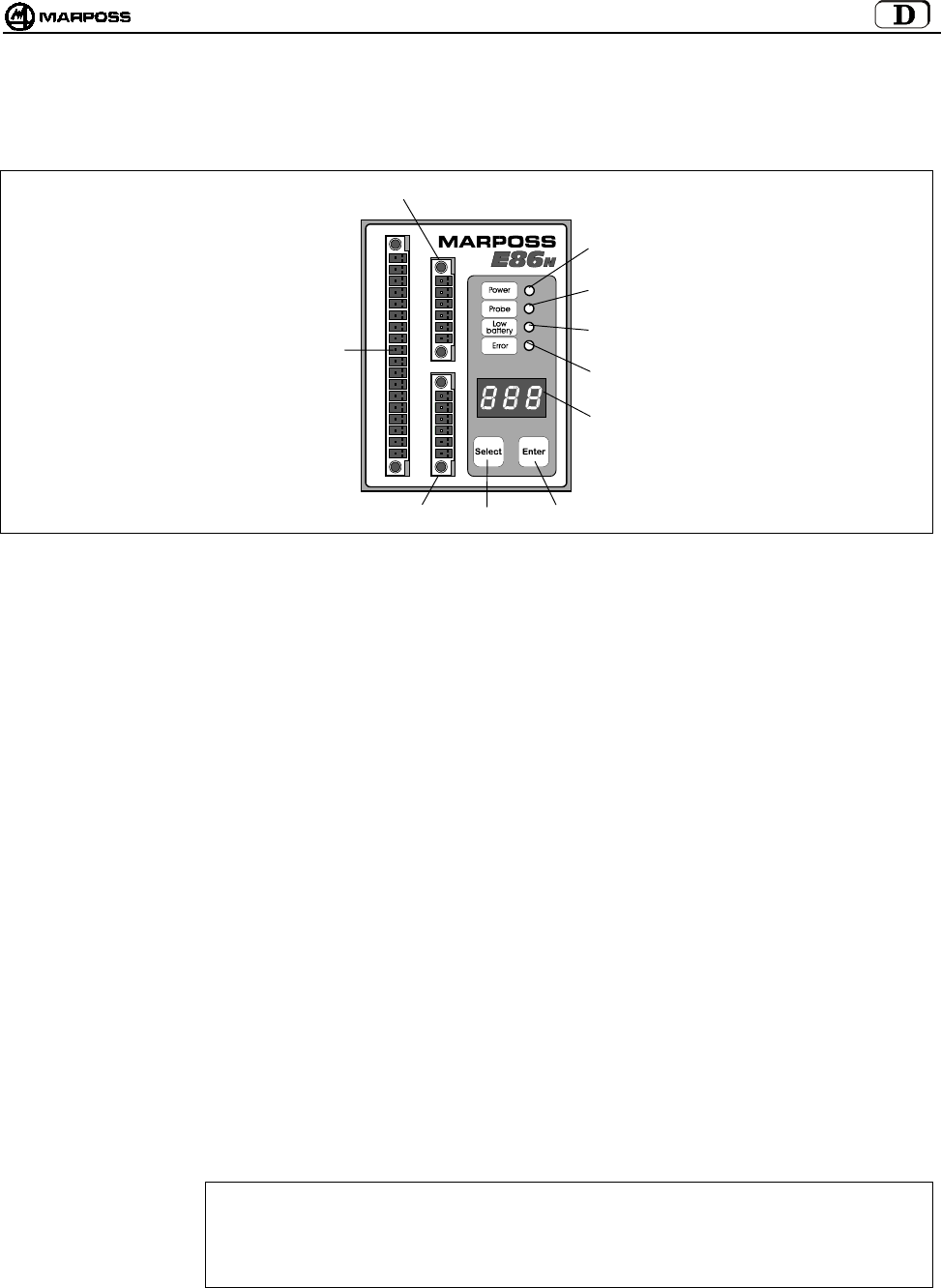
mida 111
9. SCHNITTSTELLENEINHEIT E86N
9.1 Fronttafel der Schnittstelleneinheit
Abbildung 9-1: Fronttafel.
A- LED “power” (grün) : Betriebsanzeige, wenn Versorgungsspannung anliegt.
B- LED “probe” (grün) : Statusanzeige des Schaltmesskopfs. Sie leuchtet, wenn der Tasterarm des Schaltmesskopfs
ausgelenkt ist und erlischt, wenn er sich in Ruhestellung befindet.
C- LED “low battery” (gelb) : Das Leuchten bedeutet, dass die Batterie fast leer ist (siehe Punkt 7.2 “Batterielebensdauer und
Anzeigen auf der Schnittstelleneinheit” auf S. 105 und Ausgangssignal LOW BAT Punkt 9.4
“Anschlussplan Schnittstelleneinheit” auf S. 113).
D- LED “error” (rot) : Fehleranzeige. Sie leuchtet, wenn die Übertragung nicht aktiviert ist, der Schaltmesskopf außerhalb
der Reichweite des Übertragungsbereichs ist (siehe auch Ausgangssignal ERROR 9.4 “Anschlussplan
Schnittstelleneinheit” auf S. 113) und wenn die Batterie vollkommen leer ist (siehe Punkt 7.2
“Batterielebensdauer und Anzeigen auf der Schnittstelleneinheit” auf S. 105).
E- DISPLAY : Display mit drei Ziffern und sieben Segmenten. Bei normalen Betriebsbedingungen können der
Übertragungskanal, der Identifikationscode und der Ladezustand der Batterie angezeigt werden.
Bei der Programmierung werden alle programmierbaren Werte angezeigt.
F-TASTE ENTER : Bei Betätigung von mehr als 2 Sekunden wird die Schnitt-stelleneinheit in den Programmiermodus
versetzt.
Bei der Programmierung wird durch diese Taste der gewählte Datenwert bestätigt und zum nächsten
übergegangen.
Bei gleichzeitiger Betätigung von mehr als 2 Sekunden mit der Taste <Select> lassen sich die
Alarmmeldungen am Display der Schnittstelleneinheit löschen.
G-TASTE SELECT : Bei Betätigung von weniger als 2 Sekunden lassen sich links der Identifikationscode und rechts der
Ladezustand der Batterie abrufen.
Wird die Taste mehr als 2 Sekunden lang gedrückt, kann damit das System von Hand aktiviert und
deaktiviert werden.
Bei gleichzeitiger Betätigung von mehr als 2 Sekunden mit der Taste <Enter> lassen sich die
Alarmmeldungen am Display der Schnittstelleneinheit löschen.
Bei der Programmierung dient diese Taste zum Scanning der programmierbaren Daten oder zur
Erhöhung des aktuellen Programmierwerts.
H – KLEMMLEISTE : Anschluss des Empfängermoduls (H1) und des Zusatz-empfängermoduls (H2).
ACHTUNG
Wird nur ein Empfängermodul verwendet, muss dieser immer an der unteren Klemme H1
angeschlossen werden, damit er korrekt funktioniert. Wird er hingegen an der oberen Klemme H2
angeschlossen, funktioniert das System nicht, und auf dem Display erscheint die Fehlermeldung
“E.nb” (siehe Punkt 14.1 “Fehlermeldungen” auf S. 131).
I – KLEMMLEISTE : Ein-Ausgangsanschlüsse an die SPS der CNC-Steuerung
H2
E
G
C
D
I
F
H1
A
B

DEUTSCH
E86N- Schaltmesssystem mit Funkübertragung
112
9.2 Abmessungen der Schnittstelleneinheit
Abbildung 9-2. Abmessungen.
9.3 Technische Merkmale der Schnittstelleneinheit E86N
Versorgung : 24 VDC nicht stabilisiert (13,5÷35 V)
: 300 mA max. (mit zwei angeschlossenen Empfängermodulen)
Eingangssignale : Optogekoppelte Eingänge (24V - <10mA)
-AUX IN : nicht angeschlossen (für spätere Verwendungen)
-SEL 0 - SEL 1 : Wahl des Identifikationscodes zur Ansteuerung von bis zu 4 Sendermodulen auf der gleichen Maschine
(siehe Punkt 9.4.1 “Wahl des Identifikationscodes” auf S. 113).
24V - 7 mA
-START/STOP : Aktivierung/Deaktivierung der Übertragung
Der Arbeitsspannungs-/-stromwert dieses Eingangs kann abhängig vom Typ der angeschlossenen CNC-
Steuerung (siehe Punkt 10.1 “Programmierung der Schnittstelleneinheit (Interface)” auf S. 116) mit
folgenden Werten programmiert werden:
15V – 0,5 mA (Low current-Heidenhain)
24V – 4mA (High current)
Hinweis: Die Verbindung der Eingangssignale kann vom Typ SINK (“COM” an “+24V” Leitung anschließen) oder
vom Typ SOURCE (“COM” an “0V” Leitung anschließen) sein.
Ausgangssignale : Kontakte Halbleiterrelais (SSR) 50V - 40 mA
-ERROR : Fehlermeldung
(Sendermodul mit Schaltmesskopf nicht aktiviert oder außerhalb des Übertragungsbereichs,
Sendermodulbatterie vollkommen leer mit Batterieladezustand auf Display gleich “0”.
Kontakt immer NC (Öffner)
-AUX OUT : Nicht angeschlossen (für spätere Anwendungen)
-PROBE 1/SKIP : Statussignal des Schaltmesskopfs; kann als Statussignal des Schaltmesskopfs (in Ruhestellung oder
ausgelenkt) oder als Skipsignal (Impuls) programmiert werden.
Programmierbarer Kontakt: NC oder N.A.(Öffner oder Schließer)
-PROBE 2/SKIP : Zusätzliches Statussignal für den Schaltmesskopf; kann als Statussignal des Schaltmesskopfs (in
Ruhestellung oder ausgelenkt) oder als Skipsignal (Impuls) programmiert werden.
Programmierbarer Kontakt: NC oder N.A.(Öffner oder Schließer)
-LOW BAT : Signal für Batterie schwach mit Anzeige des Batteriezustands am Display gleich “3”.
Verwendet man eine Alkalibatterie, beträgt die verbleibende Restzeit im Dauerbetrieb unter dieser
Bedingung:
• 14 Stunden für den Standardsendermodul
• 24 Stunden für den Kompaktsendermodul
Programmierbarer Kontakt N.C. oder N.A.(Öffner oder Schließer).
70
(2,76”) 51
(2,01”)
11
(0,43”)
68
(2,68”)
5,5
(0,22”)
90
(3,54”)

mida 113
9.4 Anschlussplan Schnittstelleneinheit
An der Schnittstelleneinheit befinden sich Klemmleistenstecker; die Anschlüsse werden durch Schraubklemmen an der zugehörigen
Klemmleiste vorgenommen.
Abbildung 9-3. Anschlussplan
9.4.1 Wahl des Identifikationscodes
Signal von der Maschinenlogik:
SEL 0 SEL 1 IDENTIFIKATIONSCODE
I1 I2 A
I1 I2 B
I1 I2 C
I1 I2 D
Hinweis: Wenn nur ein Sendermodul verwendet wird, sind diese 2 von der SPS der CNC-Steuerung kommenden Signale NICHT
notwendig. Die Schnittstelle ist per Default auf den Identifikationscode A eingestellt, ebenso der Sendermodul (siehe
Punkt 10.2 “Programmazione del Trasmettitore” auf S. 31).
EMPFÄNGER 1
EMPFÄNGER 2
GRÜN
BLAU
WEISS
VIOLET
SCHIRM
ROT
GRÜN
BLAU
WEISS
VIOLET
SCHIRM
ROT
COM
A
UX IN
SEL 0
SEL 1
START/STOP
STATUS AUSGANG 1
SKIP
STATUS AUSGANG 2
SKIP
BATTERIE
SCHWACH
FEHLER
A
UX OUT
+24V DC
0V
SCHUTZLEITER
CNC -MASCHINENSTEUERUNG
0V SOURCE
24V SINK
MESSKOPFAUSGANG 2
/
STATUS ODER SKIP
BATTERIE SCHWACH
FEHLER
24V
0V
VERSOR-
GUNG.
I1
I2
24V SOURCE
0V SINK
(
H1
)
(
H2
)
(
I
)
MESSKOPFAUSGANG 1/
STATUS ODER SKIP
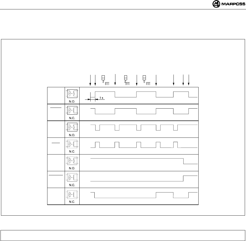
DEUTSCH
E86N- Schaltmesssystem mit Funkübertragung
114
9.5 Überblick Ein-/Ausgänge Schnittstelleneinheit E86N
Abbildung 9-4.Überblick Ein-/Ausgänge der Schnittstelleneinheit
Hinweis: In bestimmten stark durch elektromagnetische Störungen beeinflussten Arbeitsumgebungen könnte die zur Aktivierung
der Übertragung erforderliche Zeit mehr als 1 Sekunde betragen.
offen
offen
offen
offen
offen
geschlossen
geschlossen
geschlosen
geschlossen
geschlossen
offen
geschlossen
offen
geschlossen
Status
Messkopf
Status
Messkopf
Skip
Skip
Batterie
schwach
Batterie
schwach
Fehler
Signale
E86N SSR
Relais
Start
Übertragung ein
Ruhestellung
Kontaktöffnung
ausgelenkt
Kontaktschließung
Ruhestellung
Fehle
r
Fehler behoben
Batterie schwach
Übertragung aus
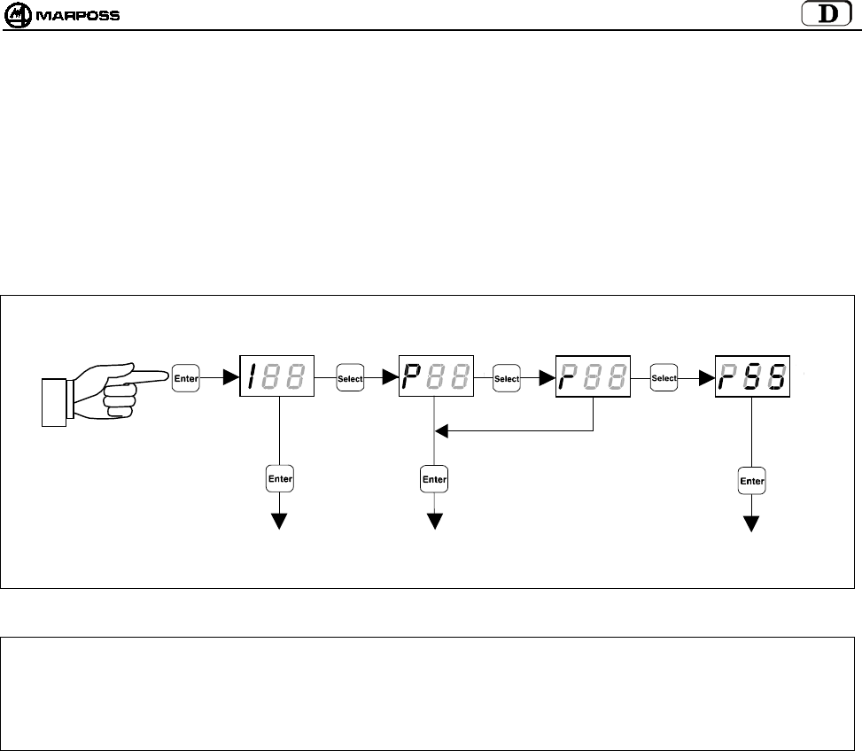
mida 115
10. PROGRAMMIERUNG DES SYSTEMS
Hält man mehr als 2 Sekunden lang die Taste “Enter” gedrückt, schaltet das System in den Programmiermodus. Dann kann mit der
Taste “Select” die Programmierart gewählt werden:
I --> Programmierung der Schnittstelleneinheit (Interface)
P --> Programmierung des Sendermoduls mit Schaltmesskopf (Probe)
r --> Programmierung des Sendermoduls im Modus "Recovery"
rSS ÆProgrammierung der "Sniffer“-Funktion
Nach erfolgter Wahl können mit den Tasten “Select” und “Enter” die Programmierdaten geändert werden. Die Taste “Select” dient zur
Erhöhung des aktuellen Datenwerts, “Enter" zur Bestätigung und zum Übergang auf den nachfolgenden Wert.
ACHTUNG: Falls lediglich der Betriebskanal neu programmiert werden soll, muss die Prozedur mit der Programmierung des
Sendermoduls begonnen werden.
Da die Schnittstelleneinheit als Default mit aktivierter Funktion Automatische Programmierung des Kanals (AP=1 –
siehe Punkt 10.1 “Programmierung der Schnittstelleneinheit (Interface) neinheit”) geliefert wird, wird am Ende der
Neuprogrammierung des Betriebskanals des Sendermoduls auch die Schnittstelleneinheit automatisch auf dem
gleichen Kanal programmiert sein.
PROGRAMMIERUNG
DES SENDERMODULS
PROGRAMMIERUNG DE
R
SCHNITTSTELLENEINHEIT
PROGRAMMIERUNG
DES SENDERMODULS
IM RECOVERY-MODUS
> 2 Sekunden
PROGRAMMIERUNG DER
"SNIFFER“-FUNKTION
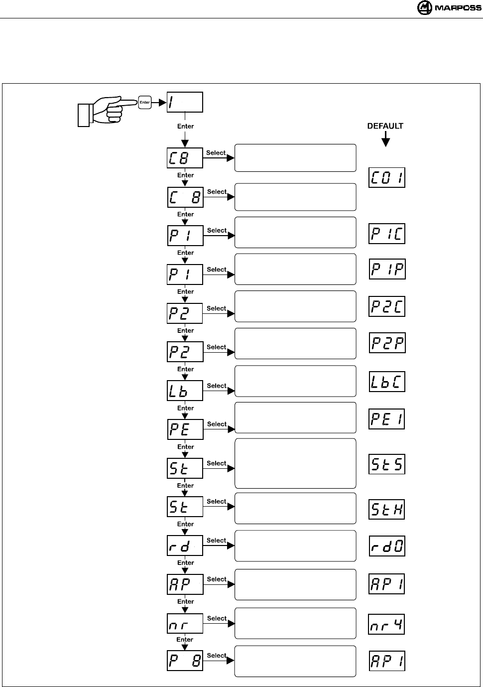
DEUTSCH
E86N- Schaltmesssystem mit Funkübertragung
116
10.1 Programmierung der Schnittstelleneinheit (Interface)
Befindet sich das System im Programmiermodus, können nach Wahl der Programmierart "I" über die Tasten “Select” und “Enter”
nacheinander folgende Werte modifiziert werden:
Hinweis: Nach Bestätigung des letzten Datenwerts verlässt man den Programmiermodus.
Man kann die Programmierung jederzeit abbrechen, indem die Taste <ENTER> mehr als 2 Sekunden lang gedrückt und
somit die aktuelle Sequenz annulliert wird.
Eingabe Übertragungskanal:
ZEHNER
Eingabe Übertragungskanal:
EINER
Messkopf Ausgang 1 :
P1C= Öffner (NC)
P1O= Schliesser (NO)
Messkopf Ausgang 1:
P1P= STATUS MESSK.
P1S= SKIP
Ausgang LOW BAT:
LbC= Öffner (NC)
LbO= Schliesser (NO)
Messk. Ausgang bei FEHLER:
PE0= Messk. in Ruhest. 0
PE1= Messk. ausgelenkt 1
Signal START:
S= Standard
P= Impulse
r= Retirgger
Signalanzeigen auf Empfäng.:
0= nein
1= ja
Eingang START:
L= 15V-0,5mA (Heidenhain)
H= Standard 24V-4mA
Autom. Kanalprogrammierung:
0= deaktiviert
1= aktiviert
Bestätigung Programmierung:
0= nein
1= ja
Messkopf Ausgang 2:
P2C= Öffner (NC)
P2O= Schliesser (NO)
Messkopf Ausgang 2:
P2P= STATUS MESSK.
P2S= SKIP
> 2 Sekunden
Anzahl der Aktivierungs-
/Deaktivierungsversuche
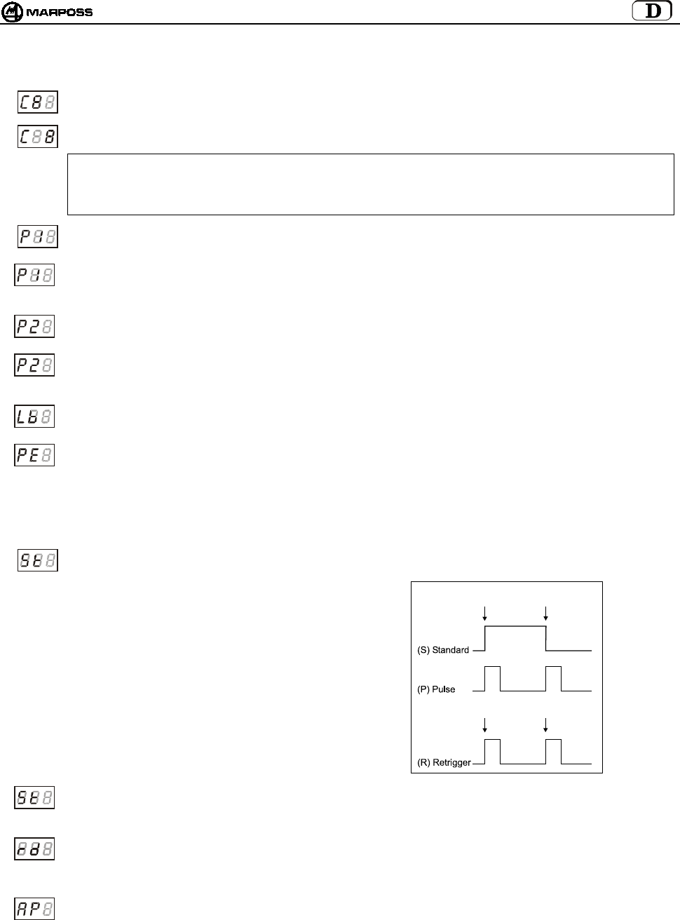
mida 117
Im Folgenden eine detaillierte Beschreibung der Programmierdaten für die Schnittstelleneinheit:
Übertragungskanal Schnittstelleneinheit – Zehner: Das Zehnerfeld blinkt, wird mit Taste “Select” zyklisch erhöht.
Übertragungskanal Schnittstelleneinheit – Einer: Das Einerfeld blinkt, wird mit Taste “Select” zyklisch erhöht.
ACHTUNG:
Zur Bestätigung der erfolgten Programmierung (P1) blinkt bei einer versehentlichen Wahl der Kanäle 65-69 oder 00 das
Display der Schnittstelleneinheit auf dem soeben falsch eingestellten Kanal. Zum Verlassen dieses Zustands einfach in
den Programmiermodus der Schnittstelle zurückkehren und den korrekten Kanal (von 1 bis 64) einstellen.
Polarität Messkopf Ausgang 1 - PROBE 1: Die ersten Digits enthalten die Angabe “P1”. Das dritte nimmt zyklisch die
Werte <C> und <O> für ÖFFNER bzw. SCHLIESSER an.
Funktionalität Messkopf Ausgang 1 - PROBE1: Die ersten Digits enthalten die Angabe “P1”. Das dritte nimmt
zyklisch die Werte ‘P’ und ‘S’ an, was normaler Ausgang (Messkopf Status) oder “Skip” (Impuls der Dauer von 44 ms
bei jeder Statusänderung des Schaltmesskopfs) bedeutet.
Polarität Messkopf Ausgang 2 - PROBE2: Die ersten Digits enthalten die Angabe “P2”. Das dritte nimmt zyklisch die
Werte <C> und <O> für ÖFFNER bzw. SCHLIESSER an.
Funktionalität Messkopf Ausgang 2 - PROBE2: Die ersten Digits enthalten die Angabe “P2”. Das dritte nimmt
zyklisch die Werte <P> und <S>, was normaler Ausgang (Messkopf Status) oder “Skip” (Impuls der Dauer von 44 ms
bei jeder Statusänderung des Schaltmesskopfs) bedeutet.
Polarität Ausgang LOW_BAT: Die ersten Digits enthalten die Angabe “lb”. Das dritte nimmt zyklisch die Werte <C>
und <O> für ÖFFNER bzw. SCHLIESSER an.
Messkopf Ausgang bei FEHLER – PROBE ERROR: Ermöglicht die Programmierung des Zustands, den die Messkopf
Ausgänge 1 und 2 bei einen der folgenden Fehlerfälle annehmen:
• Sendermodul nicht aktiviert
• Sendermodul außerhalb Übertragungsbereich
• Batterie vollkommen leer
Die ersten Digits enthalten die Angabe “PE”. Das dritte nimmt zyklisch die Werte <0> (Messkopf in Ruhestellung) und
<1> (Messkopf ausgelenkt) an.
Betriebsmodus Startsignal: Die ersten Digits enthalten die Angabe “St”. Das dritte nimmt zyklisch die Werte ‘S’
(Standard), ‘P’ (Pulse) und ‘r’ (retrigger) an.
Im Modus “Standard” aktiviert die steigende
Flanke die Übertragung des Messkopfstatus,
die fallende deaktiviert sie.
Im Modus “Pulse” aktiviert der Start-Impuls
die Übertragung des Messkopfstatus, der
Stop-Impuls deaktiviert die Übertragung.
Im Modus “Retrigger” ist die Möglichkeit zur
Deaktivierung der Übertragung des
Messkopfstatus über Funk ausgeschlossen.
Eine steigende Flanke auf dem Startsignal
startet den Timer neu, wenn die
Übertragung noch aktiv ist. In dieser
Betriebsart kann das Ausschalten des
Sendermoduls nur über den Timer erfolgen.
Eingang Start: Die ersten Digits enthalten die Angabe “St”. Das dritte nimmt zyklisch die Werte ‘L’ (Low current) und ‘H’
(High current) an. Im 15V (Anm.). Modus “low current” nimmt der Eingang circa 0.5 mA auf. In der 24V Modalität “high
current (Default)” ist der Eingang standardmäßig ausgelegt und nimmt ca. circa 4 mA.
Remote Display - Signalanzeigen: Die ersten Digits enthalten die Angabe “rd”. Das dritte nimmt zyklisch die Werte
<0> (nein, die Leds des Empfängermoduls zeigen die Funksignalstärke an) und <1> (ja, die Leds des
Empfängermoduls haben dieselben Funktionen der Leds der Schnittstelleneinheit, mit Ausnahme der mittleren grünen
Led, das dann immer aus ist) an (siehe 8.2 “Remote Display Modus” auf S. 109).
Automatische Programmierung des Übertragungskanals: Die ersten Digits enthalten die Angabe “AP”. Das dritte
übernimmt zyklisch die Werte <0> (deaktiviert - die Programmierung des Senderkanals hat keine Wirkung auf den
programmierten Wert der Schnittstelleneiheit) und <1> (aktiviert - am Ende der Programmierung des Sendermoduls
wird automatisch der Kanal von der Schnittstelleneinheit übernommen, der gerade für den Sender programmiert wurde
(siehe Punkt 10.2 “Programmierung des Sendermoduls mit Schaltmesskopf (Probe)“ auf S. 119).
*Anm.: Diese Funktion wird beim Einsatz der Verlängerung Code.6739696319 freigegeben.
Aktivierung
Aktivierung
Deaktivierun
Retrigger
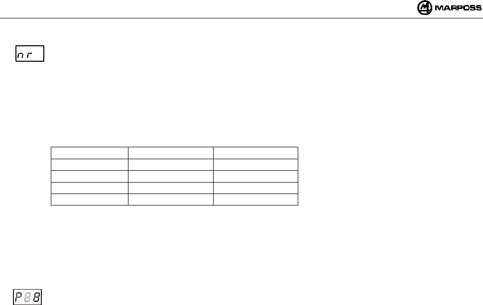
DEUTSCH
E86N- Schaltmesssystem mit Funkübertragung
118
Anzahl der aktivierungs-/deaktivierungsversuche: die ersten 2 digits geben den schriftzug „nr.“ an.
das dritte digit nimmt zyklisch die werte von 2 bis 9 an (defaultwert 4).
dieser wert ermöglicht die programmierung der anzahl der maximalen versuche, die die basisstation zur
aktivierung/deaktivierung des senders ausführt. falls nach diesen versuchen der sender nicht aktiviert/deaktiviert worden
ist, muss der schnittstelle ein neuer befehl über das startsignal gegeben werden.
die erhöhung der anzahl der versuche bedingt eine längere verzögerung der aktivierungs-/deaktivierungszeit.
für den defaultwert (nr = 4) sind die aktivierungs-/deaktivierungszeiten gemäß folgender tabelle wie folgt:
TYPISCH MAX. WERT KENNCODE
1,050 sec 4,200 sec A
1,200 sec 4,800 sec B
1,350 sec 5,400 sec C
1,500 sec 6,000 sec D
bei änderung der anzahl der versuche werden die tabellenwerte gemäß folgender gleichung geändert:
delay = default delay x (nr / 4)
gemäß tabelle hängt die aktivierungs-/deaktivierungszeit auch vom verwendeten kenncode (unterkanal) ab.
je weiter die codes voneinander entfernt sind, desto geringer ist die wahrscheinlichkeit, dass die
aktivierung/deaktivierung im falle einer großen dichte von nahen anwendungen scheitert.
Bestätigung der programmierten Daten: Das erste Digit enthält das Zeichen “P”. Das dritte nimmt zyklisch die Werte
<0> nein, Schnittstelleneinheit nicht programmieren und <1> ja, Schnittstelleneinheit programmieren, an.
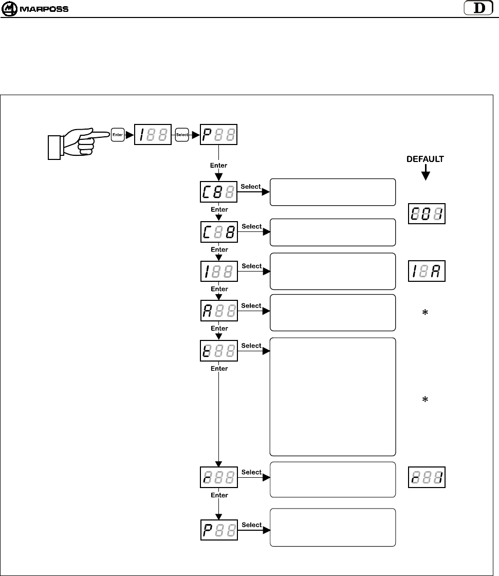
mida 119
10.2 Programmierung des Sendermoduls mit Schaltmesskopf (Probe)
Wählt man im Programmiermodus mit den Tasten “Select” und “Enter” die Programmierart “P”, können nacheinander folgende Werte
modifiziert werden:
Hinweis: Nach Bestätigung des letzten Datenwerts verlässt man den Programmiermodus.
Man kann die Programmierung jederzeit abbrechen, indem die Taste <ENTER> mehr als 2 Sekunden lang gedrückt und
somit die aktuelle Sequenz annulliert wird.
(
∗
)
Hinweis: Hängt vom Sendermodultyp ab:
- Bei einem Sendermodul mit Funkaktivierung wird der Parameter "Art der Aktivierung" auf Funk und die "Einschaltzeit"
auf den Wert <5>, der 2'14" entspricht, per Default programmiert sein.
- Bei einer Schalteraktivierung wird der Parameter "Art der Aktivierung" auf Schalter und die Einschaltzeit auf den Wert
<8>, der einer unendlichen Zeit entspricht, per Default programmiert sein.
Eingabe Übertragungskanal:
ZEHNER
Eingabe Übertragungskanal:
EINER
Identifikationscode:
(A, B, C, D)
A
rt der Aktivierung:
0= Funk
1= Schalter
Einschaltzeit:
0= 4"
1= 8"
2= 17"
3= 34"
4= 1'7"
5= 2'14"
6= 4'28"
7= 8'57"
8= ∞
Rettrigger des Timers:
0= Deaktiviert
1= Aktiviert
Bestätigung Programmierung:
0= nein
1= ja
> 2 Sekunden
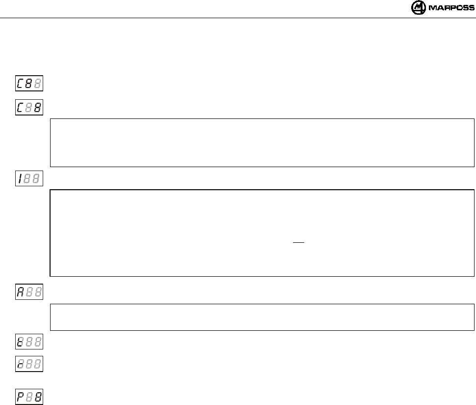
DEUTSCH
E86N- Schaltmesssystem mit Funkübertragung
120
Im Folgenden eine detaillierte Beschreibung der Programmierdaten für den Sendermodul:
Übertragungskanal – Zehner:
Das Zehnerfeld blinkt, wird zyklisch vom Wert <0> auf den Wert <6> erhöht.
Übertragungskanal – Einer: Das Einerfeld blinkt, wird zyklisch vom Wert <0> auf den Wert <9> erhöht.
ACHTUNG:
Zur Bestätigung der erfolgten Programmierung (P1) blinkt bei einer falschen Wahl der Kanäle 65-69 oder 00 auf dem
Display der Schnittstelle der Kanal, auf den die Schnittstelle eingestellt wurde. Ein Reset des Sendermoduls ist nur im
Modus “Recovery” möglich (siehe 10.3 “Programmierung des Sendermoduls im Recovery-Modus” auf S. 121).
Identifikationscode: Das erste Digit enthält das Zeichen “I”. Für das dritte sind die Werte <A, B, C, D> einstellbar.
ACHTUNG:
Ein Sendermodul ist durch die Nummer des Übertragungskanals und den Identifikationscode (z.B. 12B) vollständig
identifiziert.
Da der Identifikationscode für den Sendermodul programmierbar, aber eine Eingabe von der externen Logik (CNC) für
die Schnittstelle ist, wird empfohlen, diesen Parameter am Sender nur zu modifizieren, wenn man sicher ist, dass er
genau dem der Schnittstelle entspricht. Anderenfalls wird das System durch das Fehlen des Datenverkehrs nicht
funktionieren. Die einzige Möglichkeit zur Wiederinbetriebnahme ist dann ein Programmiervorgang des Sendermoduls
im Modus “Recovery” (siehe Punkt 10.3 “Programmierung des Sendermoduls im Recovery-Modus” auf S. 121).
Art derAktivierung: Das erste Digit enthält das Zeichen “A”. Das dritte nimmt zyklisch die Werte <0> zur
Funkaktivierung und <1> zur Schalteraktivierung an.
ACHTUNG:
Den auf der vorhergehenden Seite angegebenen Defaultwert belassen.
Einschaltzeit: Das erste Digit enthält das Zeichen “t”. Das dritte wird mit einem Wert zwischen <0 und 8> eingestellt,
was einer Betriebszeit entspricht, die von mindestens “4” (Wert 0) bis unendlich (Wert 8) geht.
Retrigger des Timers: Das erste Digit enthält das Zeichen “r”. Das dritte nimmt zyklisch die Werte <0> für Retrigger
deaktiviert und <1> für Retrigger aktiviert an.
Dieser Datenwert ermöglicht die Rückstellen des Timers auf 0 nach jeder Statusänderung des Schaltmesskopfs.
Bestätigung der programmierten Daten. Das erste Digit enthält das Zeichen “P”. Das dritte nimmt zyklisch die Werte
<0> nein, für Sendermodul nicht programmieren und <1> ja, für Sendermodul programmieren, an.
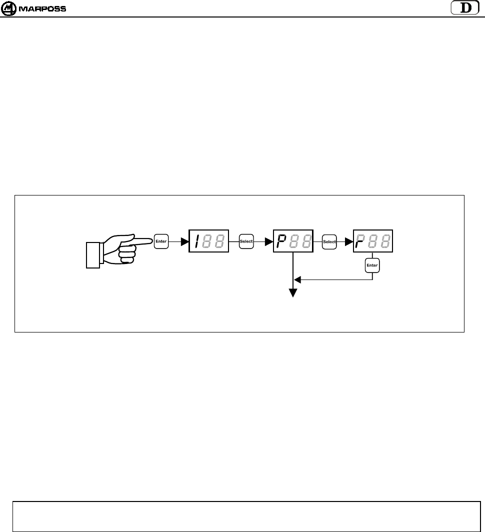
mida 121
10.3 Programmierung des Sendermoduls im Recovery-Modus
Falls eine der folgenden Bedingungen für den Sendermodul auftritt:
a. Übertragungskanal des Sendermoduls unbekannt
b. Programmierung des Übertragungskanals falsch (z.B. 65-69 oder 00)
c. Programmierung des Identifikationscodes falsch (anders als Schnittstelleneinheit)
ist ein Programmierverfahren des Sendermoduls vorgesehen, das “Recovery” genannt wird und die Rückverfolgung und eventuelle
Modifizierung der Sendermodulparameter ermöglicht.
Die Prozedur besteht aus folgenden Schritten:
1. Die Schnittstelleneinheit eingeschaltet lassen, die Stromzufuhr zum Sendermodul unterbrechen (bei Funkaktivierung des
Sendermoduls den Batteriefachdeckel abschrauben (siehe Punkt 15.1.2 "Einsetzen/Auswechseln der Sendermodulbatterie"
Seite 132), bei Schalteraktivierung des Sendermoduls den Mikroschalter am Steilkegel frei lassen).
2. Auf der Schnittstelleneinheit den Programmiermodus aufrufen und die Programmierart "r" anwählen;
3. Durch Drücken von <ENTER> erscheint am Display die Meldung "REC".
4. Den Tasterarm am Schaltmesskopf auslenken und ihn in dieser Position halten während der Sendermodul unter Strom gesetzt
wird (bei Funkaktivierung den Batteriedeckel schließen, bei Schalteraktivierung den Mikroschalter am Steilkegel drücken).
5. Der Sendermodul wird auf einem Betriebskanal, anstatt auf dem programmierten Übertragungskanal aktiviert. Auf dem Display
der Schnittstelleneinheit erlischt die Meldung “REC”, und es wird die Nummer des Übertragungskanals (mit blinkenden
Zehnern) angezeigt, auf den der Sender programmiert war.
6. Den Tasterarm loslassen und den Sendermodul eingeschaltet lassen (Deckel geschlossen /Mikroschalter auf Steilkegel
gedrückt halten)
Jetzt kann man nach Erhalt der gewünschten Information
• Programmiermodus abbrechen, indem die Taste <ENTER> mehr als 2 Sekunden lang gedrückt wird oder der Deckel
abgeschraubt bleibt//Mikroschalter frei gelassen wird,
• eine normale Programmierung des Sendermoduls vornehmen, wie es in Punkt 10.2 “Programmierung des Sendermoduls mit
Schaltmesskopf (Probe)” auf S. 119 beschrieben ist.
ACHTUNG: Ist auf der Schnittstelleneinheit die “automatische Programmierung des Kanals” (AP=1 – siehe Punkt
Programmierung der Schnittstelleneinheit (Interface) “ neinheit”) aktiviert, wechselt bei beendeter
Sendermodulprogrammierung auch der Schnittstellenkanal, indem er sich dem des Sendermoduls anpasst.
> 2 Sekunden
PROGRAMMIERUNG
DES SENDERS
(
siehe Punkt 10.2
)

DEUTSCH
E86N- Schaltmesssystem mit Funkübertragung
122
10.4 Belegungsanalyse des elektromagnetischen Spektrums („SNIFFER“-Funktion)
Die Belegungsanalyse des elektromagnetischen Spektrums wird in zwei Phasen ausgeführt.
• Scanning
Die Schnittstelle E86N führt zyklisch ein Scanning aller 64 Kanäle aus und speichert dabei für einen jeden Kanal die maximale
Amplitude des empfangenen Signals.
• Anzeige der Ergebnisse
Die Schnittstelle E86N zeigt die Kanäle und die während dem vorhergehenden Scanning gespeicherte maximale Amplitude an.
Zur Aktivierung der Funktion muss die Schnittstelle auf „Programmiermodus“ geschaltet werden ("Enter“ länger als 2 Sekunden lang
drücken). Mehrere Male die Taste "Select“ drücken, bis auf dem Display "rSS“ angezeigt wird. Danach "Enter“ drücken.
XX XX XX XX
> 2 Sekunden
> 2 Sekunden > 2 Sekunden > 2 Sekunden > 2 Sekunden
Enter =Liste ▲
Select= Liste ▼
Enter =Liste ▲
Select= Liste ▼
Enter =Liste ▲
Select= Liste ▼
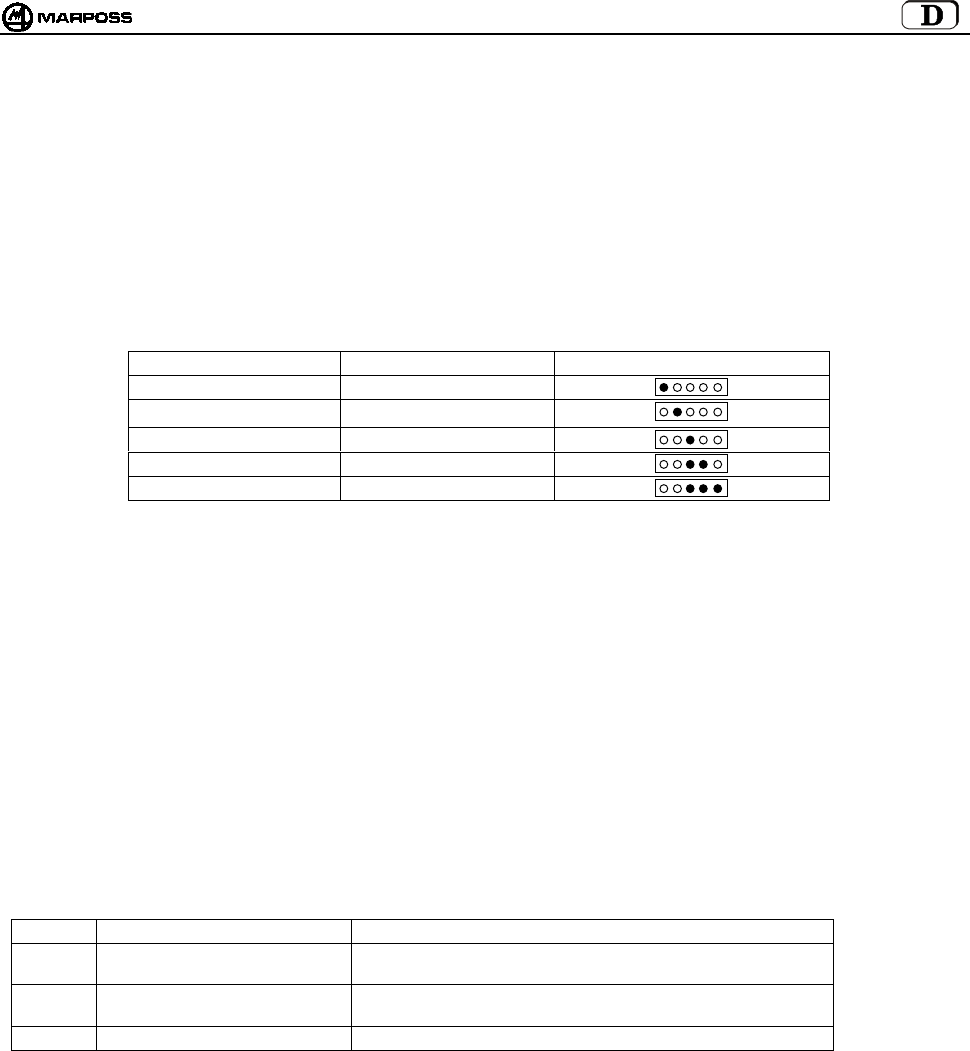
mida 123
10.4.1 Scanning
"Select“ drücken, bis auf dem Display „St“ (Start) angezeigt wird.
Durch Drücken von „Enter“ wird das Scanning aktiviert, das ausgeführt wird, bis die "Enter“-Taste erneut länger als 2 Sekunden
gedrückt wird.
Das Scanning kann auch für lange Zeiten aktiviert sein.
Während des Scannings ist die "Select“-Taste nicht aktiv.
Auf dem Display werden die folgenden Daten in der angegebenen Reihenfolge angezeigt:
• Nummer des erfassten Kanals “Cnn” (nn= Kanalnummer 01-64, zusätzlich zum Aktivierungskanal "CA”);
• die entsprechende Amplitude des Signals "XX“.
Die Signalamplitude wird in logarithmischer Skala ausgedrückt und kann von –9 bis 99 variieren (siehe Tabelle unten).
SIGNALNIVEAU ANGEZEIGTER WERT LED BASISSTATION
unter schwelle ≤ -1
viel unten (1) 0 / 3
unten 4 / 7
mittel 8 / 11
oben ≥ 12
HINWEISE:
1. Der Wert <0> entspricht dem min. Signalniveau, das als „erfassbar“ betrachtet wird (Amplitude –102dBm und
Signal/Geräuschverhältnis > -12dB).
2. Wenn die Scanning-Funktion aktiv ist, sind alle anderen Funktionen deaktiviert (Zustand der Ausgänge der E86N wie im
Fehlerzustand).
3. Die erfassten max. Werte werden in einem nicht permanenten Speicher gespeichert, weshalb sie bei der Abschaltung verloren
gehen.
4. Wenn ein Scanning aktiviert wird, werden die vorhergehenden max. Werte, die erfasst wurden, gelöscht.
5. Die Scanningzeit beträgt ca. 1 Sekunde pro Kanal. Ein komplettes Scanning nimmt demnach ca. 70 Sekunden in Anspruch.
Da das System nur jeweils einen Kanal erfassen kann, wird die Wahrscheinlichkeit, dass elektromagnetische Signale von
kurzer Dauer erfasst werden, durch Verlängerung der Beobachtungszeit erhöht.
6. Die erfassten Werte sind nur dann verfügbar, wenn mindestens ein komplettes Scanning ausgeführt worden ist.
7. Falls es sich um zwei Basisstationen handelt, wird der größere der beiden erfassten Werte verwendet.
10.4.2 Anzeige der Ergebnisse
Die Ergebnisse eines Scannings können auf Grundlage von drei verschiedenen Ordnungstypen angezeigt werden:
Symbol Ordnung Erstes Element der Liste
HI Empfangenes Signal abfallend Kanal, an dem das Signal mit der maximalen Amplitude
empfangen worden ist.
LO Empfangenes Signal ansteigend Kanal, an dem das Signal mit der minimalen Amplitude
empfangen worden ist.
CH Ansteigende Kanalnummer Kanal 00
Zur Anzeige der Ergebnisse "Select“ drücken, bis auf dem Display das der gewünschten Ordnung entsprechende Symbol erscheint.
Danach die "Enter“-Taste drücken.
Auf dem Display wird zunächst die Kanalnummer und danach der Signalwert angezeigt.
• Durch Drücken der "Enter“-Taste kann man zum nächsten Element der Liste bis zum letzten wechseln.
• Durch Drücken der "Select“-Taste kehrt man auf das vorhergehende Element bis zum ersten zurück.
• Zum Verlassen der Liste die "Enter“-Taste länger als 2 Sekunden drücken.
Rote
Gelbe
Grüne
Grüne
Grüne

DEUTSCH
E86N- Schaltmesssystem mit Funkübertragung
124
11. ANBAU DER SCHALTMESSKÖPFE AM STANDARDSENDERMODUL
11.1 Montage des Schaltmesskopfs am Standardsendermodul
Für die Montage und Demontage des Schaltmesskopfs am Sendermodul ist folgendermaßen vorzugehen:
Hinweis:
Beim Einbau des Schaltmesskopfs den einwandfreien Zustand und korrekten Sitz der Dichtringe sicherstellen.
SCHALTMESSKOPF T25/TL25 und TT25
- Den Flansch (A) mit dem mitgelieferten großen Schlüssel (A1) an den Sendermodul schrauben.
- Den Kopf mit dem mitgelieferten kleinen Schlüssel (A2) an den Flansch (A) schrauben.
SCHALTMESSKOPF T36
- Den Schaltmesskopf mit den Schrauben (B1) am Flansch (B) befestigen.
- Den Flansch (B) mit dem mitgelieferten großen Schlüssel an den Sendermodul schrauben.
SCHALTMESSKOPF T60 und TT60
- Den Schaltmesskopf mit den Schrauben (C1) am Flansch (C) befestigen.
- Den Flansch (C) mit dem mitgelieferten großen Schlüssel an den Sendermodul schrauben.
Hinweis:
Bei beendetem Vorgang sollte das System ausgerichtet werden.
Abbildung 11-1
A
2
A
T25/TL25-TT25
B1 B
T36
C1
C
T60-TT60
A
1
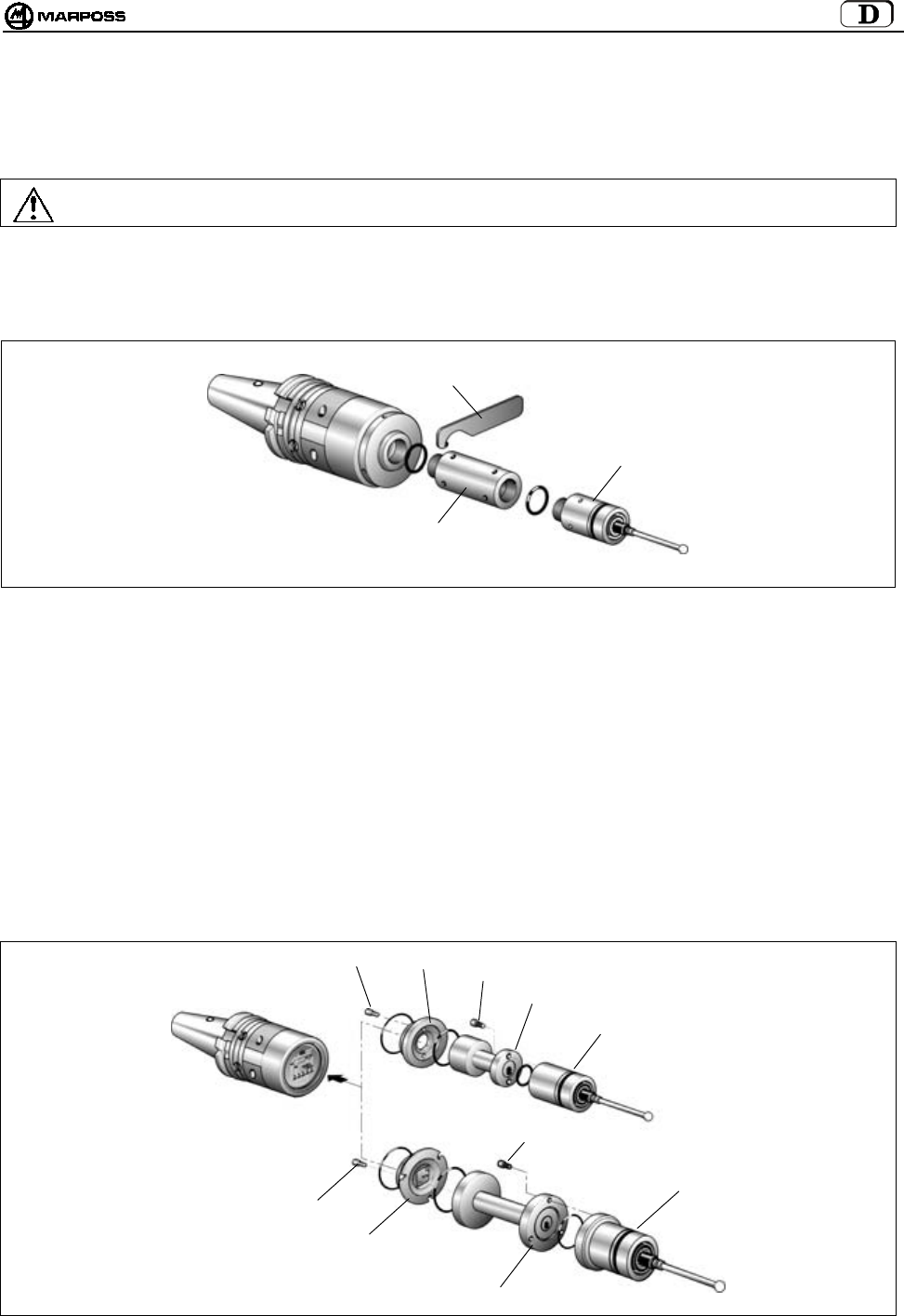
mida 125
11.2 Einbau der Verlängerungen für Schaltmessköpfe (Option)
Eine Verlängerung wird zwischen Schaltmesskopf und Sendermodul eingesetzt, um in größere Messtiefen eindringen zu können, ohne
den Tasterarm länger als nötig zu machen. Für den Einbau der Verlängerungen folgendermaßen vorgehen.
Warnung:
Beim Einbau der Verlängerung den einwandfreien Zustand und korrekten Sitz der Dichtringe sicherstellen.
• Verlängerung für Schaltmesskopf T25/TL25/TT25
- Den Schaltmesskopf mittels des mitgelieferten Schlüssels (A1) vom Adapterring am Sendermodul abschrauben.
- Die Verlängerung mit Dichtring (A2) zwischen Schaltmesskopf und Sendermodul (A2) einsschrauben.
- Die Verlängerung und den Kopf mit dem Schlüssel (A1) festziehen.
Abbildung 11-2
• Verlängerung für Schaltmesskopf T36
- Den Flansch (B) vom Sendermodul abschrauben.
- Den Schaltmesskopf durch Entfernen der Schrauben (B1) vom Flansch (B) abmontieren.
- Die Verlängerung (B2) mit den Schrauben (B1) am Flansch (B) befestigen.
- Die Gruppe Flansch-Verlängerung mit dem Schlüssel am Sendermodul festschrauben.
- Den Schaltmesskopf mit den Schrauben (B3) an der Verlängerung montieren.
• Verlängerung für Schaltmesskopf T60/TT60
- Den Flansch (C) vom Sendermodul abschrauben.
- Den Schaltmesskopf durch Entfernen der Schrauben (C1) vom Flansch (C) abmontieren.
- Die Verlängerung (C2) mit den Schrauben (C1) am Flansch (C) befestigen.
- Die Gruppe Flansch-Verlängerung mit dem Schlüssel am Sendermodul festschrauben.
- Den Schaltmesskopf mit den Schrauben (C3) an der Verlängerung montieren.
Abbildung 11-3
A
2
A1
T25/TL25/TT25
B1
T60/TT60
BB3
B2
C1
C
C2
T36
C3

DEUTSCH
E86N- Schaltmesssystem mit Funkübertragung
126
12. MONTAGE DES SENDERMODULS
12.1 Montage des Sendermoduls mit Standardflansch
- Die Batteriefachdeckel (C) des Sendermoduls - Schrauben (D) - entfernen, um zu den vier Befestigungsbohrungen (E) am
Flansch zu gelangen.
- Am Kegel vier Gewindebohrungen M4x8 (A) und eine zentrale Ansenkung (B) anbringen, siehe Ausschnitt in Figura 12-1.
- Zwischen Sendermodul und Kegel die mitgelieferte Kugel (G) ø6 mm einsetzen.
- Den Sendermodul mit den vier Schrauben (F) am Kegel befestigen.
Ausrichtung des Systems
- Den Tasterarm montieren (siehe "MONTAGE DES TASTERARMS").
- Die Mitte der Tasterarmkugel mit den vier Schrauben (F) zur Achse des Kegels ausrichten.
- Nach Ausrichtung des Systems die vier Schrauben (F) kreuzweise festziehen, Batterie einfügen und die Batteriefachdeckel
anschrauben.
Abbildung 12-1
D
C
D
C
F
E
F
34
(1,34”)
34
(1,34”)
4,5
±
0,1 mm
(0,177 ± 0,004)

mida 127
12.2 Montage des Sendermoduls mit Regulierflansch
1. Die Batteriefachdeckel des Sendermoduls abschrauben (siehe Punkt 12.1).
HINWEIS: Die in den folgenden Punkten 2 - 3 - 4 und 5 beschriebenen Arbeitsgänge gelten nur für Sendermodule mit
Funkaktivierung. Sendermodule mit Schalteraktivierung (Mikroschalter auf Kegel) werden mit Kegel und
bereits am Sendermodul montierten Regulierflanschen geliefert. In diesem Fall ab Punkt 6 fortfahren.
2. Den Standardflansch (C) des Sendermoduls abschrauben, vier Schrauben (D) .
3. Teil (E) des Regulierflansches mit den vier Schrauben (D) am Sendermodul befestigen.
Abbildung 12-2
4. Am Kegel zwei Gewindebohrungen M4x8 (F) anbringen, siehe Auschnitt in Abb.12-2
5. Das Teil (G) des Regulierflansches mit den beiden Schrauben (H) am Kegel befestigen.
HINWEIS: Um die Orientierung der LED (L) am Sender zur Bedienseite zu erleichtern, stehen drei Bohrungspaare für eine
optimale Orienterung zur Verfügung.
6. Den Sendermodul anbauen; dabei darauf achten, dass die 4 Gewinde (M) des Teils (G) den 4 Langlöchern (N) des Teils (E)
des Regulierflansches gegenüberstehen.
7. Die 4 Gewindebolzen (P) in die Langlöcher (N) einführen und in die Gewinde (M) des Kegelseitigen Fflansches mit dem
mitgelieferten Innensechskantschlüssel einschrauben.
8. Die vier Spezialmuttern (Q) auf die Gewindebolzen aufschrauben.
Abbildung 12-3
D
C
D
E
P
QL
M
G
N
E
FG
H
H
F=M4x8
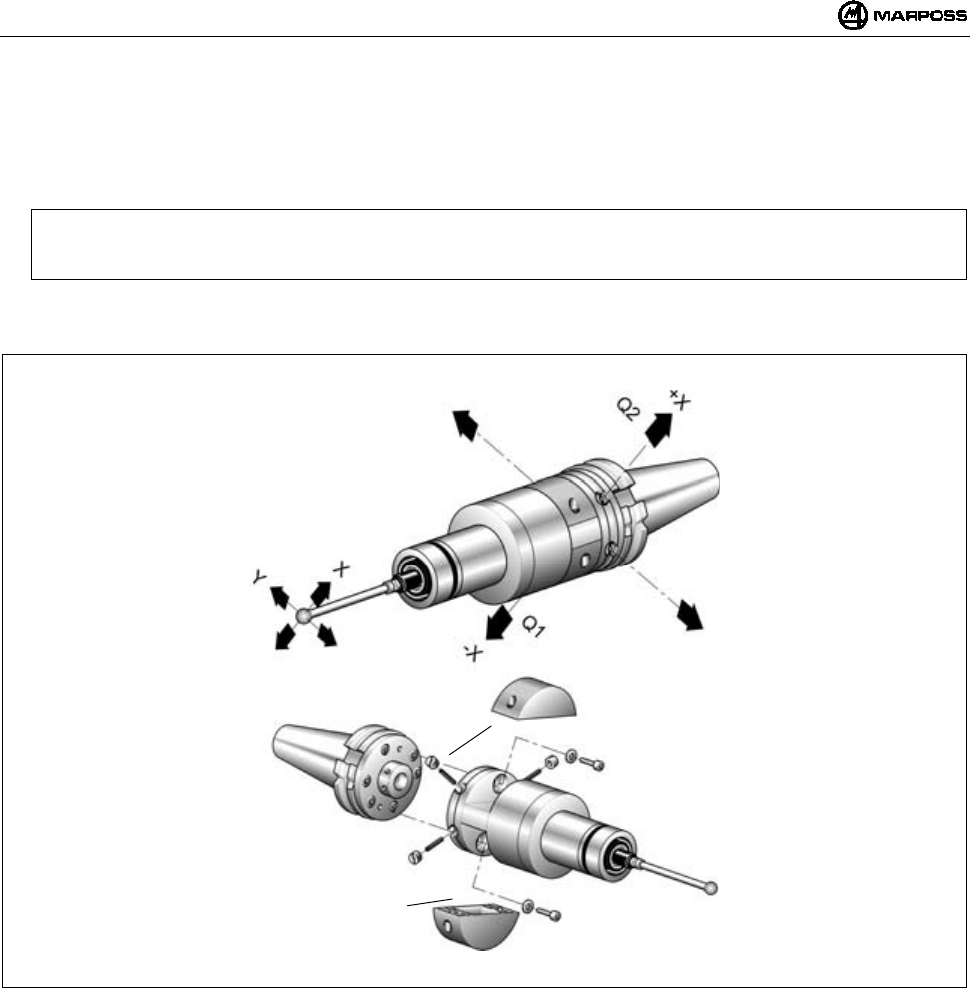
DEUTSCH
E86N- Schaltmesssystem mit Funkübertragung
128
Ausrichtung des Systems
9. Den Tasterarm des Schaltmesskopfs montieren (siehe "MONTAGE DES TASTERARMS").
10. Die Mitte der Tasterarmkugel durch Betätigung der vier Spezialmuttern und der Gewinde-bolzen (Q). auf die Kegelachse
ausrichten. Die max. zulässige Verschiebung beträgt 1,7 mm in die vier Richtungen.
Beispiel:
Verschiebung der Tasterarmkugel Richtung "-X" —>(Q1) lockern und (Q2) festziehen.
Ebenso für die anderen Richtungen verfahren.
11. Nach der Ausrichtung des Systems muss die Reguliergruppe gesichert werden. Dazu die beiden Feststellschrauben (R)
einsetzen und stark anziehen.
Abbildung 12-4
R
R
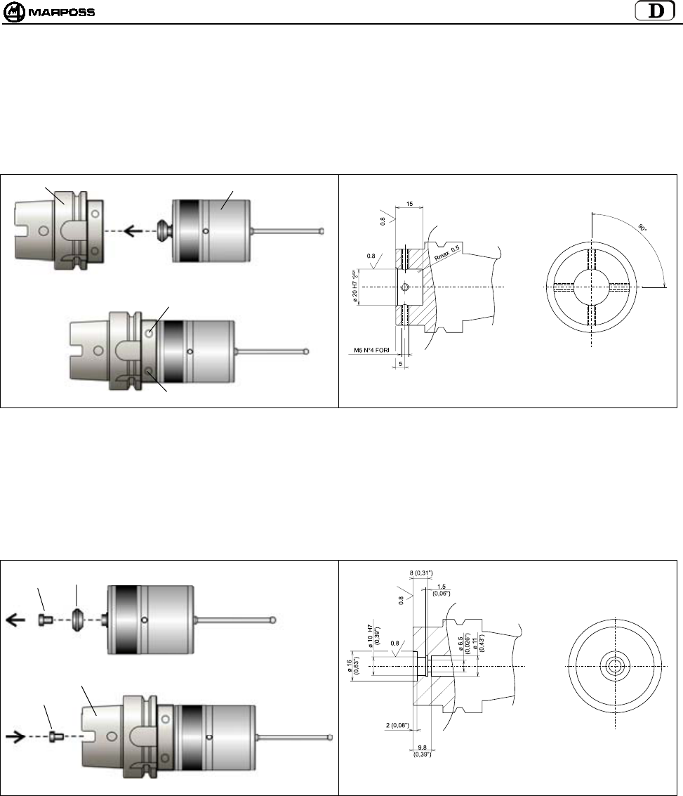
mida 129
12.3 Montage des Kompaktsendermoduls auf dem Kegel
12.3.1 Befestigung des Kompaktsendermoduls am Kegel (Bearbeitung des Kegels)
• Den Sendermodul (B) in den Kegel (A) einschieben.
• Den Sendermodul mit den vier Gewindestiften (C) am Kegel befestigen.
Abbildung 12-5. Befestigung des Sendermoduls am Kegel. Abbildung 12-6. Bearbeitung des Kegels
12.3.2 Befestigung des Kompaktsendermoduls ohne konischen Zapfen am Kegel (Bearbeitung des Kegels)
• Die Schraube (A) ausdrehen, mit der der konische Zapfen am Sendermodul (B) befestigt ist.
• Den Sendermodul (B) in den Kegel (C) einschieben.
• Den Sendermodul mit der Schraube (A) befestigen.
Abbildung 12-7. Befestigung des Sendermoduls am Kegel Abbildung 12-8. Bearbeitung des Kegels
A
B
A
B
C
C
C
A
A
C
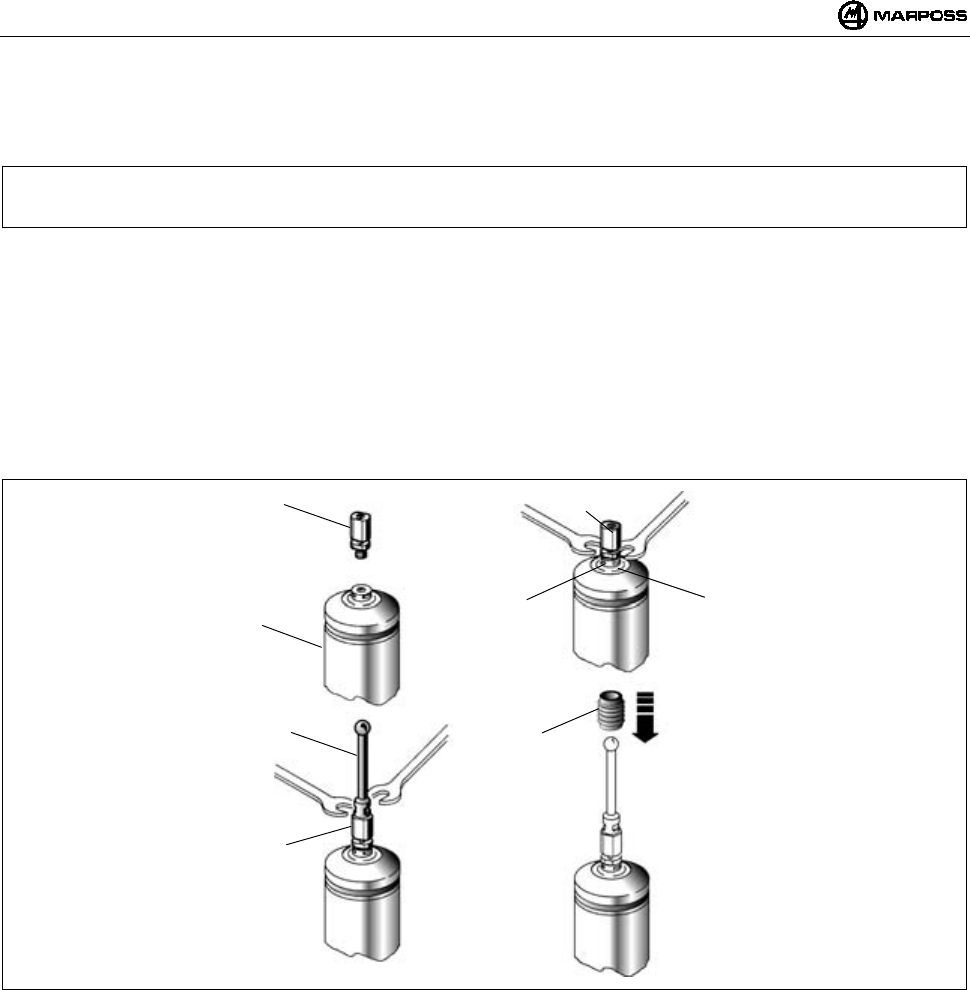
DEUTSCH
E86N- Schaltmesssystem mit Funkübertragung
130
13. MONTAGE DES TASTERARMS
Im Folgenden wird beschrieben, wie der Tasterarm an dem Schaltmesskopf angebracht wird. Da der Schaltmesskopf beim
Kompaktsendermodul eingebaut ist und der Tasterarmhalter gleich ist, gilt für beide Sendermodultypen die gleiche Prozedur.
Hinweis: Für den nachfolgenden Ablauf ist ein Sollbruchstück vorgesehen. Dieser Stift zwischen Tasterarm und
Schaltmesskopf hat die Funktion, den Schaltmesskopf bei versehentlichen Stößen gegen den Tasterarm zu
schützen, indem er bricht und den Tasterarm vom Schaltmesskopf löst.
• Das Sollbruchstück (A) am Schaltmesskopf (B) einschrauben.
• Mit dem (mitgelieferten) Schlüssel den Tasterarmhalter (C) des Schaltmesskopfs festhalten und mit dem anderen Schlüssel
das Sollbruchstück (A) festziehen. Der Schlüssel zum Festspannen des Stifts (A) muss in Position (D) eingesteckt werden.
• Den Tasterarm (F) am Sollbruchstück (A) einschrauben.
• Mit einem Schlüssel den Stift festhalten und mit dem anderen den Tasterarm festziehen.
• Die Sicherungshülse (E) einsetzen, indem sie am Tasterarm entlang geschoben wird, bis sie das Sollbruchstück (A) umhüllt.
Diese Sicherungshülse hat den Zweck, den Tasterarm bei einem Bruch des Sollbruchstücks festzuhalten.
• Bei Funk sollte eigentlich kein Stahltaster verwendet werden, sondern wegen eventueller Interferenzen (sehr
unwahrscheinlich) ein Keramiktasterarm. Dann den Tasterarm direkt am Schaltmesskopf aufschrauben: mit einem Schlüssel
den Tasterarmhalter (C) festhalten, mit dem anderen den Tasterarm festziehen.
Abbildung 13-1
A
B
F
A
A
DC
E
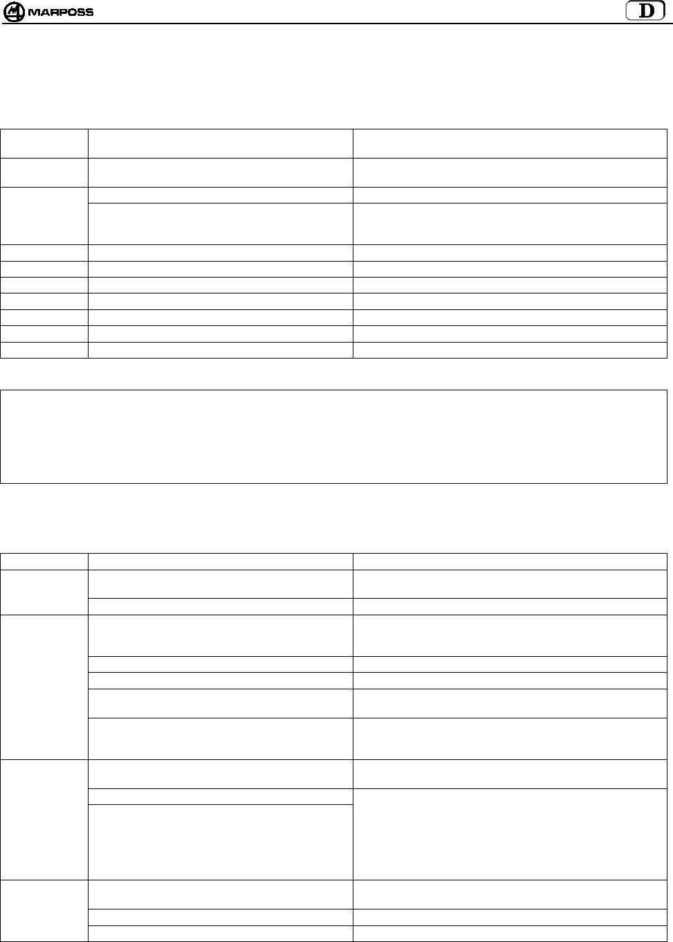
mida 131
14. DIAGNOSE
14.1 Fehlermeldungen
Am Display der Schnittstelleneinheit E86N können folgende Fehlermeldungen auftreten:
FEHLERMELD
UNG
URSACHE MASSNAHME
E.E2 Lese-/Schreibfehler Technischen Kundendienst kontaktieren oder alle Daten neu
programmieren.
E.nb Kein Empfängermodul angeschlossen Empfängermodulanschluss prüfen.
Falsch angeschlossener Empfängermodul Sicherstellen, dass im Fall von nur einem Empfängermodul
dieser an die untere Klemme (H1) der Schnittstelle
angeschlossen ist.
E.b1 Kommunikationsfehler mit Empfängermodul 1 Verbindung mit Empfängermodul 1 prüfen.
E.b2 Kommunikationsfehler mit Empfängermodul 2 Verbindung mit Empfängermodul 2 prüfen.
F.P1 Fehler (Kurzschluss) auf Ausgang PROBE 1 Verbindung auf Ausgang PROBE 1 prüfen.
F.P2 Fehler (Kurzschluss) auf Ausgang PROBE 2 Verbindung auf Ausgang PROBE 2 prüfen.
F. Er Fehler (Kurzschluss) auf Ausgang ERROR Verbindung auf Ausgang ERROR prüfen.
F. Lb Fehler (Kurzschluss) auf Ausgang LOW_BAT Verbindung auf Ausgang LOW_BAT prüfen.
F. Au Fehler (Kurzschluss) auf Ausgang AUX Verbindung auf Ausgang AUX prüfen.
Hinweis: Nach Behebung der Fehlerursachen können die Fehleranzeigen durch gleichzeitiges Drücken der Tasten <Select> und
<Enter> für mehr als 2 Sekunden gelöscht werden (mit Ausnahme der Meldungen E.b1 und E.b2 die durch Ausschalten
und erneutes Einschalten gelöscht werden).
ACHTUNG:
Das Ein- oder Ausschalten des Systems muss immer bei angeschlossenem/n Empfängermodulstecker/n erfolgen.
14.2 Led Anzeigen
Die Leds auf der Fronttafel der Schnittstelleneinheit können Folgendes anzeigen:
URSACHE MASSNAHME
Stromausfall Prüfen ob an den Enden der Klemmen 16 und 17 auf der
Klemmleiste der Schnittstellen-einheit Spannung anliegt.
LED "POWER"
ERLOSCHEN
Rücksetzbare Sicherung ausgelöst Einige Minuten bei nicht eingeschalteter Schnittstelle warten.
Sendermodulantenne außerhalb
Übertragungsbereich
Sicherstellen, dass bei den Bewegungen des
Schaltmesskopfs die grüne Led ""tuning"" am
Empfängermodul erleuchtet bleibt.
Sendermodulbatterie vollkommen leer oder fehlend Neue Batterie einsetzen
Übertragungszeit abgelaufen Ein Startsignal zur Reaktivierung des Systems geben.
Keine elektrische Verbindung zwischen
Empfängermodul und Schnittstelleneinheit
Das Kabel des Empfängers und die entsprechenden
Verbindungen zur Schnittstelleneinheit prüfen.
LED "ERROR"
ERLEUCHTET
"
Elektrische oder elektromagnetische Störung Das vom Empfängermodul kommende Kabel von eventuell
vorhandenen Leistungskabeln entfernen. Übertragungskanal
wechseln.
Keine elektrische Verbindung zwischen
Schaltmesskopf und Sendermodul.
Verbindung zwischen Schaltmesskopf und Sendermodul
prüfen.
Schaltmesskopf beschädigt
LED
"PROBE":
WECHSELT
STATUS
NICHT BEIM
BERÜHREN
BZW. BEIM
AUSLENKEN
DES TASTERS
Sendermodul beschädigt
Schaltmesskopf vom Sendermodul abmontieren, die
Federkontakte untereinander anschließen und den Kontakt
unterbrechen. Wenn die Led trotzdem nicht umschaltet, ist
der Sendermodul defekt. Eine Statusänderung bedeutet,
dass der Schaltmesskopf defekt ist.
Tasterarm locker Sicherstellen, dass Tasterarm und Sollbruchstück (falls
verwendet) gut am Schaltmesskopf festgeschraubt sind
Flansch locker Alle Schrauben festziehen.
SCHLECHTE
WIEDERHOL-
BARKEIT
Loch oder Beschädigung an der Innendichtung Schaltmesskopf auswechseln
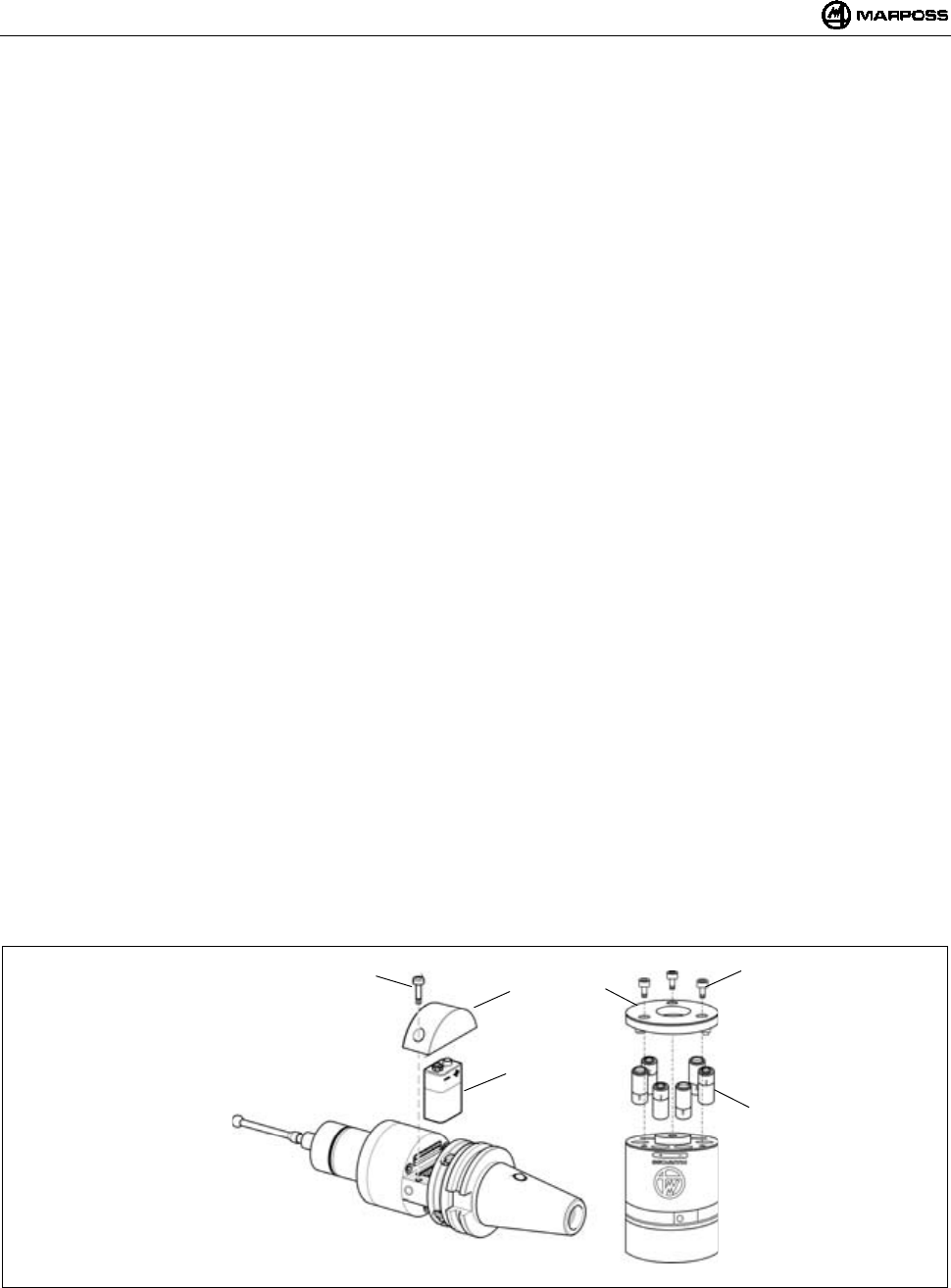
DEUTSCH
E86N- Schaltmesssystem mit Funkübertragung
132
15. WARTUNG
15.1 Laufende Instandhaltung
15.1.1 Reinigung und Kontrollen
Damit das Messsystem stets optimale Leistungen erbringt, sollte es regelmäßig gereinigt und geprüft werden.
Es handelt sich um einfache Arbeiten, die, abhängig von den Einsatzbedingungen, in bestimmten Abständen ausgeführt werden sollten.
- Überprüfung des einwandfreien Zustands der Verkabelung
Regelmäßig die Unversehrtheit der Kabel und den festen Sitz der Kabelklemmen prüfen.
- Prüfung der Dichtungen
Der Schaltmesskopf ist an der Vorderseite durch zwei Dichtungen geschützt, die unter normalen Betriebsbedingungen einen
optimalen Schutz gewährleisten. In regelmäßigen Abständen prüfen, ob die Außendichtung keine Verletzungen aufweist. Ggf. die
Messkopfkappe mit Dichtung erneuern.
Bei einer Beschädigung der Innendichtung muss der Schaltmesskopf zur Reparatur an die nächste Marposs Niederlassung
geschickt werden.
15.1.2 Einsetzen/Auswechseln der Sendermodulbatterie
Zum Einsetzen der Batterie in den Sendermodul oder zum Auswechseln, wenn sich die Led "low battery" auf der Tafel der
Schnittstelleneinheit eingeschaltet hat (Batteriestand auf Display = 3) und wenn das Ausgangssignal LOW BATTERY aktiviert wurde,
folgendermaßen vorgehen:
• STANDARDSENDERMODUL:
- Die beiden Schrauben (A) des mit dem Batteriesymbol gekennzeichneten Deckels (C) lösen.
- Die leere Batterie, falls vorhanden, herausnehmen und die neue Batterie (B) in die Kontakte des Deckels (C) unter Beachtung der
Polung einsetzen.
- Den Deckel (C) wieder schließn unter Beachtung der Position der Kontakte.
- Die Schrauben (A) mit einem Anzugsmoment von 2Nm festziehen.
• KOMPAKTSENDERMODUL:
- Die drei Schrauben (D) des Deckels (F) lösen und den Deckel abnehmen.
- Die leeren Batterien, falls vorhanden, herausnehmen und die neuen Batterien (E) in die Aufnahmen einsetzen. Auf die am
Sendermodulkörper angegebene Polung achten.
- Den Deckel (F) wieder schließen und dabei auf die Kontakte achten.
- Die Schrauben (D) mit einem Anzugsmoment von 2Nm festziehen.
Im Punkt 7.2 “Batterielebensdauer und Anzeigen auf der Schnittstelleneinheit" auf Seite 105 ist die Dauer der Batterie im Verhältnis zum
Einsatz und zum Batterietyp angegeben.
Abbildung 15-1. Einsetzen/Auswechseln der Batterien
F
A
B
C
D
E
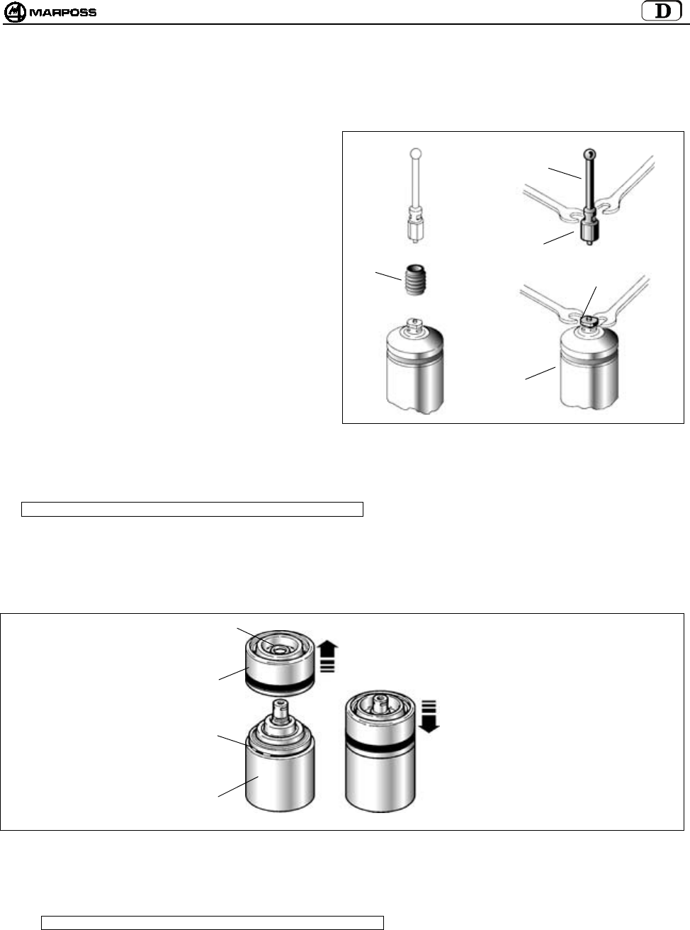
mida 133
15.2 Außerplanmäßige Wartung
15.2.1 Auswechseln des Sollbruchstücks /Tasterarms
Bei versehentlichen Stößen an den Tasterarm
folgendermaßen vorgehen, um das gebrochene
Sollbruchstück und/oder den Tasterarm auszuwechseln.
1. Die Sicherungshülse (A) vom gebrochenen
Sollbruchstück bzw verbogenen Tasterarm entfernen.
2. Das gebrochene Sollbruchstück (D) vom Tasterarm
(B) und Schaltmesskopf (C) entfernen
3. bzw. den beschädigten Tasterarm vom
Schaltmesskopf (C) abmontieren.
HINWEIS: Diese Arbeitsgänge ausführen, indem
der Tasterarmhalter des
Schaltmesskopfs mit dem mitgelieferten
Schlüssel festgehalten wird.
4. Dann das neuen Sollbruchstück und den Tasterarm
montieren (siehe "Montage des Tasterarms")
Abbildung 15-2
15.2.2 Auswechseln der Messkopfkappe
Hinweis: Gilt nur für Schaltmessköpfe auf Standardsendermodulen.
1- Den Tasterarm und ggf. das Sollbruchstück entfernen.
2- Die vordere Schutzkappe (B) mit Dichtung (C) vom Schaltmesskopf (A) abmontieren.
3- Den Zustand des Dichtrings (D) prüfen und eventuell auswechseln.
4- Die neue Messkopfkappe montieren und einrasten.
Abbildung 15-3
15.2.3 Auswechseln des Schaltmesskopfs/Sendermoduls
Hinweis: Gilt nur für Schaltmessköpfe auf Standardsendermodulen.
1- Den Tasterarm und eventuell das defekte Sollbruchstück entfernen.
Siehe "MONTAGE DES TASTERARMS".
2- Den Schaltmesskopf auswechseln, wie es in "ANBAU DER SCHALTMESSKÖPFE AM STANDARDSENDERMODUL"
beschrieben ist.
A
D
B
C
D
D
B
C
A
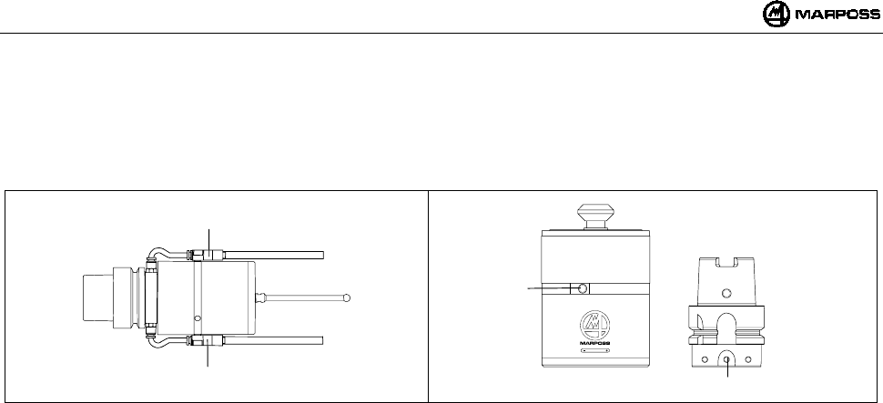
DEUTSCH
E86N- Schaltmesssystem mit Funkübertragung
134
16. ZUBEHÖRTEILE
16.1 Reinigungslufteinheit für Kompaktsendermodul
Die Reinigungslufteinheit (A) muss auf den entsprechenden Gewinden (B) am Sendermodul und am Kegel (Abbildung 16-2) befestigt
werden. Der Luftdruck sollte ≤6 bar (88.175psi) betragen. Anschließend die Blasröhrchen auf die Tasterkugel ausrichten.
Abbildung 16-1 Abbildung 16-2
A
B
A
B

mida 135
17. ERSATZTEILLISTE
ART. NR. BESCHREIBUNG ANMERKUNGEN
1019108005 Sollbruchstück Länge 15 mm
1019108003 Sicherungshülse
2915335018 Dichtungssatz für T25/TL25/TT25 UMFASST: Messkopfkappe mit Dichtung, vorderer und
hinterer O-Ring, Sicherungshülse
2915340010 Dichtungssatz für T36G UMFASST: Messkopfkappe mit Dichtung, vorderer und
hinterer O-Ring, Sicherungshülse
2915345007 Dichtungssatz für T60G/TT60 UMFASST: Messkopfkappe mit Dichtung, vorderer und
hinterer O-Ring, Sicherungshülse
2915335013 Messkopfkappe für T25/TL25/TT25
2915340006 Messkopfkappe für T36
2915345012 Messkopfkappe für T60
3415335200 Schaltmesskopf T25G
3415335201 Schaltmesskopf T25S
3424306040 Schaltmesskopf TL25G
3424306041 Schaltmesskopf TL25S
3415340200 Schaltmesskopf T36G
3415340201 Schaltmesskopf T36S
3415345030 Schaltmesskopf T60G
3415345050 Schaltmesskopf T60S
3424310000 Schaltmesskopf TT25
3424310100 Schaltmesskopf TT25H
3424451000 Schaltmesskopf TT60
2019923021 Adapter auf Sendermodul für T25/TL25/TT25 Mit O-Ring
2019923022 Adapter auf Sendermodul für T36 Mit O-Ring
2019923023 Adapter auf Sendermodul für T60/TT60 Mit O-Ring
2915335023 Verlängerung für T25/TL25/TT25 L=23,50 mm
2915335100 Verlängerung für T25/TL25/TT25 L=50 mm
2915335105 Verlängerung für T25/TL25/TT25 L=75 mm
2915335110 Verlängerung für T25/TL25/TT25 L=100 mm
2915335120 Verlängerung für T25/TL25/TT25 L=150 mm
2915340125 Verlängerung für T36 L=50 mm
2915340126 Verlängerung für T36 L=100 mm
2915340127 Verlängerung für T36 L=150 mm
2915345040 Verlängerung für T60/TT60 L=50 mm
2915345050 Verlängerung für T60/TT60 L=100 mm
2915345060 Verlängerung für T60/TT60 L=150 mm
3019917110 Steilkegel SK40 DIN 69871/A mit Schalter und Regulierflansch
3019917130 Steilkegel SK50 DIN 69871/A mit Schalter und Regulierflansch
3019917180 Hohlschaftkegel HSK63A DIN 69893 mit Schalter und
Regulierflansch
3019917170 Hohlschaftkegel HSK100A DIN 69893 mit Schalter und
Regulierflansch
1502027040 Dichtung für Batteriefach
1502027050 Dichtung für Batteriefach (Kontaktseite)
1502018260 Spezialschraube für Batterieträger
4162100005 Alkaliblockbatterie 9V
4162100302 Lithiumblockbatterie 9V
6180830500 Batteriefachdeckel ohne Kontakte
2015340100 Schlüsselsatz UMFASST: Maullschlüssel für Tasterarm und Sechs-
kantschlüssel:
1,5 – 2 – 2,5 – 3 – 4 mm
1320131000 Spezialhakenschlüssel für T25/TL25/TT25
1320367000 Spezialhakenschlüssel für Flansch T25/TL25/T36/T60/TT25/TT60
2919917110 Regulierflansch für Standardsendermodul
6871982001 Sendermodul E86N mit Funkaktivierung
STANDARDSENDER E86N UND SCHALTMESSKÖPFE
6871982101 Sendermodul E86N mit Schalteraktivierung

DEUTSCH
E86N- Schaltmesssystem mit Funkübertragung
136
ART. NR. BESCHREIBUNG ANMERKUNGEN
1019108005 Sollbruchstück Länge 15 mm
1019108003 Sicherungshülse
2015340100 Schlüsselsatz: UMFASST: Maullschlüssel für Tasterarm und Sechs-
kantschlüssel:
1,5 – 2 – 2,5 – 3 – 4 mm
4400000219 Dichtungen OR 2081 PARKER 2-19 (für Batteriedeckel)
4306400804 Schrauben TCCE UNI-5931-12K M4X8 (für Batteriedeckel)
4162100004 Alkalibatterie 1,5V
6180980085 Reinigungslufteinheit
KOMPAKTSENDERMODUL
6871983000 Sendermodul E86N-P mit Funkaktivierung
6871980000 Empfängermodul E86N
6180985017 Anschlusskabel Empfängermodul 15m
EMPFÄNGERMODUL UND
ANSCHLUSSKABEL MIT STECKER
6180985027 Anschlusskabel Empfängermodul 30m
SCHNITTSTELL
EN-EINHEIT
8304870000 Schnittstelleneinheit E86N
ZUBERHÖRTEILET
6739696319 ANSCHLUßKABEL – E86N CNC HEIDEN HAIN

mida 137
E86N
SYSTEME TOUCH A TRANSMISSION RADIO
Manuel d’installation et utilisation

FRANÇAIS
E86N- Systeme touch a transmission radio
138
Il est interdit de jeter dans l’environnement et d’éliminer comme déchet urbain ou
déchet générique le produit y compris tous ses composants, sous-ensembles et
produits consommables faisant partie intégrante du produit au moment de la mise au
rebut. (Transposition nationale des directives européennes 2002/95/CE et 2002/96/CE
et autres). Les dispositions de loi s’appliquent uniquement aux produits définis DEEE
portant le marquage prévu à cet effet et mis sur le marché à partir du 13 août 2005.
Le produit DEEE mis au rebut peut contenir des substances et des pièces nocives pour l’homme et pour
l’environnement qui doivent recevoir un traitement professionnel pour être réutilisées, recyclées ou
définitivement éliminées.
Confier le produit DEEE à un centre autorisé pour le traitement DEEE, ou contacter le responsable local
ou le centre d’assistance Marposs le plus proche pour plus d’informations.
L’élimination illégale d’un produit DEEE est un acte répréhensible par la loi.
2002/95/CE
2002/96/CE
Marposs S.p.A. se réserve le droit d'apporter des modifications au produit sans avis préalable.
Toute intervention par des personnes non agréées, prétendument basée sur le contenu de ce manuel, est strictement interdite.
Face à de telles interventions, la garantie du produit est considérée comme nulle et non avenante.
Emis :11.2005 (UTD/MU)

mida 139
Table des matières
1. CONSIGNES ET MISES EN GARDE GENERALES........................................................................................................................... 141
2. COMPOSANTS DU SYSTEME............................................................................................................................................................ 142
3. CONFIGURATION ET FONCTIONNEMENT....................................................................................................................................... 143
4. MODE D’EMPLOI................................................................................................................................................................................. 144
5. SONDE ET EMETTEUR COMPACT E86N-P...................................................................................................................................... 145
6. TRANSMISSION RADIO...................................................................................................................................................................... 146
6.1 Description ................................................................................................................................................................................... 146
6.1.1 Distances à respecter entre systèmes .................................................................................................................................. 146
6.2 Activer la transmission ................................................................................................................................................................. 147
6.2.1 Activation radio ...................................................................................................................................................................... 147
6.2.2 Activation mécanique ............................................................................................................................................................ 147
6.3 Désactiver la transmission........................................................................................................................................................... 147
6.3.1 Activation radio ...................................................................................................................................................................... 147
6.3.2 Activation mécanique ............................................................................................................................................................ 147
7. EMETTEUR E86N ................................................................................................................................................................................ 148
7.1 Description ................................................................................................................................................................................... 148
7.2 Durée de vie des piles ................................................................................................................................................................. 149
7.3 Dimensions émetteur avec sondes.............................................................................................................................................. 150
7.3.1 Emetteur standard avec flasque standard............................................................................................................................. 150
7.3.2 Emetteur standard avec flasque réglable .............................................................................................................................. 151
7.4 Dimensions émetteur compact .................................................................................................................................................... 152
7.4.1 Emetteur compact E86N-P.................................................................................................................................................... 152
7.4.2 Emetteur compact E86N-P sans queue conique................................................................................................................... 152
8. RECEPTEUR E86N.............................................................................................................................................................................. 153
8.1 Antenne et prolongateur avec connecteur ................................................................................................................................... 153
8.2 Mode afficheur distant.................................................................................................................................................................. 153
8.3 Raccorder l’antenne..................................................................................................................................................................... 153
8.4 Monter l'antenne .......................................................................................................................................................................... 154
9. UNITE D’INTERFACE E86N................................................................................................................................................................ 155
Panneau frontal de l’unité d’interface.................................................................................................................................................... 155
9.2 Dimensions de l’unité d’interface ................................................................................................................................................. 156
9.3 Caractéristiques techniques Interface E86N................................................................................................................................ 156
9.4 Raccorder l’unité d’interface ........................................................................................................................................................ 157
9.4.1 Sélectionner le code identificateur......................................................................................................................................... 157
Diagramme des E/S unité d’interface E86N.......................................................................................................................................... 158
10. PROGRAMMER LE SYSTEME ......................................................................................................................................................... 159
Programmer l’interface.......................................................................................................................................................................... 160
10.2 Programmer l’émetteur ................................................................................................................................................................ 163
10.3 Programmer l’émetteur dans le mode Recovery ......................................................................................................................... 165
10.4 Analyse occupation du spectre électromagnétique (fonction “Sniffer”)........................................................................................ 166
10.4.1 Balayage................................................................................................................................................................................ 167
10.4.2 Affichage des résultats .......................................................................................................................................................... 167
11. MONTER LA SONDE – EMETTEUR STANDARD............................................................................................................................ 168
11.1 Monter la sonde – émetteur standard .......................................................................................................................................... 168
11.2 Installer un prolongateur pour sondes (optionnel) ....................................................................................................................... 169
12. MONTER L’EMETTEUR .................................................................................................................................................................... 170
12.1 Monter l’émetteur standard sur le cône ....................................................................................................................................... 170
12.2 Monter l’émetteur standard sur le cône avec flasque réglable .................................................................................................... 171
12.3 Monter l’émetteur compact E86N-P sur le cône .......................................................................................................................... 173
12.3.1 Fixer l’émetteur E86N-P sur le cône (percer le cône) ........................................................................................................... 173
12.3.2 Fixer le cône sur l’émetteur E86N-P sans queue conique (percer le cône) .......................................................................... 173
13. MONTER LE STYLET........................................................................................................................................................................ 174
14. DIAGNOSTIC ..................................................................................................................................................................................... 175
14.1 Messages d’erreur ....................................................................................................................................................................... 175
14.2 Comment interpréter les LEDs..................................................................................................................................................... 175
15. MAINTENANCE ................................................................................................................................................................................. 176
15.1 Maintenance ordinaire ................................................................................................................................................................. 176
15.1.1 Nettoyage et contrôles........................................................................................................................................................... 176
15.1.2 Installer/Remplacer la pile de l’émetteur ............................................................................................................................... 176

FRANÇAIS
E86N- Systeme touch a transmission radio
140
15.2 Maintenance extraordinaire.......................................................................................................................................................... 177
15.2.1 Remplacer la goupille de rupture/stylet ................................................................................................................................. 177
15.2.2 Remplacer le joint externe ..................................................................................................................................................... 177
15.2.3 Remplacer la sonde/l’émetteur .............................................................................................................................................. 177
16. Accessoires....................................................................................................................................................................................... 178
16.1 Groupe support air de nettoyage pour Emetteur compact........................................................................................................... 178
17. PIECES DETACHEES........................................................................................................................................................................ 179
mida 141
1. CONSIGNES ET MISES EN GARDE GENERALES
AVANT-PROPOS
Ce manuel d'instruction contient toutes les informations spécifiques nécessaires à la connaissance et à l'emploi de l'instrument Marposs
en votre possession.
Ce manuel s'adresse aux catégories d'utilisateurs suivantes:
• Personnel MARPOSS ou du Client qui doit effectuer directement l'installation de l'instrument.
• Personnel technique du Client qui doit opérer directement sur l'instrument MARPOSS.
• Personnel technique du Client responsable de la maintenance de la ligne de production sur laquelle l'instrument MARPOSS est
installé.
TOUS DROITS RESERVES. CE MANUEL NE PEUT ETRE UTILISE PAR LE CLIENT QUE POUR UN USAGE INTERNE. TOUT AUTRE USAGE EST INTERDIT.
GARANTIE
Les vices de matériau sont couverts par la garantie dans les limites suivantes :
• DURÉE DE LA GARANTIE : la garantie couvre le produit et toutes les réparations effectuées dans les délais prévus par le contrat de
vente.
• OBJET DE LA GARANTIE : la garantie s’applique au produit et à ses pièces portant un numéro d’immatriculation ou un autre
numéro d’identification MARPOSS.
La garantie décrite ci-dessus peut être modifiée par un accord entre MARPOSS et le Client.
CONSIGNES DE SECURITE GENERALES
L'instrument a été construit conformément à la réglementation CEI EN60950.
CONVENTIONS ET SYMBOLES UTILISES
Nous avons adopté dans la rédaction de ce manuel des conventions typographiques.
Plus précisément, nous avons utilisé deux types d’avis de danger :
Mise en garde :
Cet avis indique un danger qui pourrait provoquer la perte de données ou un dommage pour l’unité électronique et les
autres dispositifs qui lui sont reliés.
Attention :
Cet avis indique un danger pour l’opérateur ou pour le technicien.
Les informations particulièrement importantes qui peuvent faciliter la compréhension et l’utilisation du système sont encadrées et
précédées d’un "Nota bene", en caractères gras.

FRANÇAIS
E86N- Systeme touch a transmission radio
142
2. COMPOSANTS DU SYSTEME
A1 - Sonde et émetteur E86N (standard)
A2 - Emetteur E86N-P (compact)
B - Goupille de rupture (optionnelle)
C - Bague du stylet (optionnelle)
D - Stylet
E - Antenne
F - Unité d’interface E86N
G - Deux clés à fourche pas 5 – 5,5 et un jeu de clés six pans
H - Une clé spéciale pour sonde T25 et prolongateurs mécaniques
I - Prolongateur pour sondes (optionnelle)
L - Antenne auxiliaire (optionnelle)
Figure 2-1. Composants du système
A1
B
C
D
E
G
F
H
I
L
A2
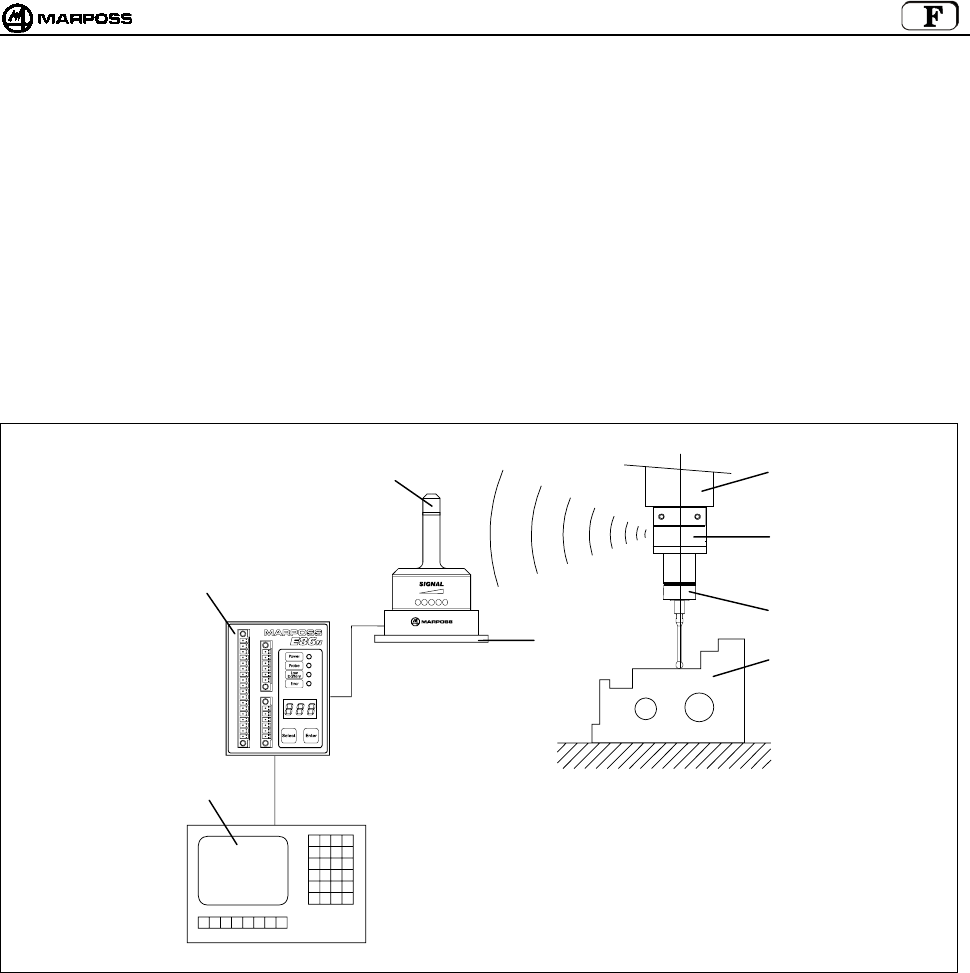
mida 143
3. CONFIGURATION ET FONCTIONNEMENT
Le système touch à transmission radio sert à identifier des points dans l’espace, qui traités par la CN de la machine à outil déterminent
des mesures. Ces points sont détectés par une sonde, un microrupteur multidirectionnel de précision, et envoyés par le système de
transmission radio, formé d’un émetteur et d’un récepteur, à l’unité d’interface qui les adapte à la CN. Le cycle de mesure appelle le
groupe sonde/émetteur monté sur le porte-outil dans le magasin d’outils et l’introduit dans le mandrin. Le système est facile à utiliser et
a été conçu pour fonctionner dans des milieux industriels particulièrement hostiles. Il est utilisé sur des centres d’usinage et fraiseuses
pour l’identification, le positionnement, le mesurage de la pièce avant l’usinage et le mesurage de la pièce après l’usinage.
Dans une application typique, ce système est formé de :
A - Pièce à mesurer E - Mandrin machine-outil
B - Stylet F - Antenne E86N
C - Sonde touch G - Unité d’interface E86N
D - Emetteur E86N H - CN de la machine outil
Figure 3-1. Configuration et fonctionnement
BA
C
D
E
F
G
H

FRANÇAIS
E86N- Systeme touch a transmission radio
144
4. MODE D’EMPLOI
Le système de mesure est multidirectionnel dans l’hémisphère x/y/+z.
Le contact du stylet sur la superficie de la pièce à inspectionner génère un signal utilisé par la machine-outil pour mémoriser le
point de contact et pour arrêter les axes machine. Pour avoir une bonne répétabilité du système, il est recommandé d’utiliser
une vitesse de mesure constante.
La vitesse de mesure choisie doit consentir un arrêt de l’axe machine dans les limites extracourse de la sonde utilisée.
Avant d’utiliser la sonde, il faut compenser l’erreur de mesure systématique du système formé d’une sonde, d’une machine-
outil et d’une CN, en effectuant un étalonnage. L’erreur systématique est caractéristique de chaque direction de mesure et elle
est répétable, c’est pourquoi l’étalonnage doit être effectué dans chaque direction où la mesure sera prise. Pour étalonner le
système, il est recommandé de mesurer des points en machine d’une valeur connue (R) et calculer les différences entre ceux-
ci et les valeurs mesurées (R+K1). Cette différence (K1) doit être saisie dans les paramètres correcteurs d’outils de la CN et
rappelée chaque fois qu’on effectue une mesure dans la même direction.
Figure 4-1. Mode d’emploi
X/Y X/Y
Z
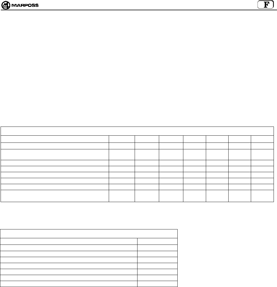
mida 145
5. SONDE ET EMETTEUR COMPACT E86N-P
La sonde de mesure est un microrupteur multidirectionnel de précision utilisée dans les applications sur machines à enlèvement de
matière à CN, pour le contrôle et la mesure des outils et des pièces.
Il existe plusieurs modèles de sondes touch multidirectionnelles dans l’hémisphère x/y/+z.
Pour certains modèles de sonde, il existe deux versions différentes suivant le type de protection frontale :
• “Version G” avec garniture toilée pour une meilleure protection contre le liquide de refroidissement.
• “Version S” avec écran en métal de protection contre les déchets d’usinage.
Pour résoudre de façon optimale les exigences spécifiques à chaque machine-outil, Marposs a créé les sondes suivantes :
Sonde T25G / T25S
Sonde TL25G / TL25S
Sonde T36G / T36S
Sonde T60G / T60S
Sonde TT25 (avec garniture, exclusivement)
Sonde TT25H (avec garniture, exclusivement)
Sonde TT60 (avec garniture, exclusivement)
Table 5-1. Caractéristiques techniques de la sonde.
Type sonde T25 TL25 T36 T60 TT25 TT25H TT60
Axes sonde ±X, ±, Y+Z±X, ±Y, +Z±X, ±Y, +Z±X, ±Y,+Z±X, ±Y,+Z±X, ±Y,+Z±X, ±Y,+Z
Répétabilité unidirectionnelle sonde (2 σ) avec une vitesse
max. de 600 mm/min.
0,5 µm0,5 µm0,5 µm1 µm1 µm2 µm1 µm
Force de mesure sur le plan X, Y 200 gf 90 gf 260 gf 280 gf 50-95 gf 90-175 gf 70-120 gf
Force de mesure dans la direction Z 1200 gf 550 gf 1200 gf 1200 gf 580 gf 1080 gf 580 gf
Extracourse sur le plan X, Y 11,2 mm 11,2 mm 14,4 mm 22 mm 11,6 mm 11,6 mm 19 mm
Extracourse dans la direction Z4 mm 4 mm 4,2 mm 6,4 mm 4 mm 4 mm 6,4 mm
CARACTERISTIQUES SE REFERANT A UN STYLET DE 35 mm 35 mm 40 mm 50 mm 35 mm 35 mm 50 mm
Degré de protection
Normes CEI
IP67 IP67 IP67 IP67 IP67 IP67 IP67
Contrairement à l’émetteur standard, sur lequel n’importe quelle sonde de mesure mentionnée dans la Table 5-1 peut être montée,
l’émetteur compact E86N-P a une sonde incorporée. Ses caractéristiques techniques sont les suivantes :
Table 5-2. Caractéristiques techniques de l’émetteur compact.
Axes ±X, ±, Y+Z
Répétabilité unidirectionnelle (2 σ) à une vitesse max. de 600 mm/min. 0,5 µm
Force de mesure sur le plan X, Y 200 gf
Force de mesure dans la direction Z 1200 gf
Extracourse sur le plan X, Y 11,2 mm
Extracourse dans la direction Z4 mm
CARACTERISTIQUES SE REFERANT A UN STYLET DE 35 mm
Degré de protection suivant normes CEI IP68
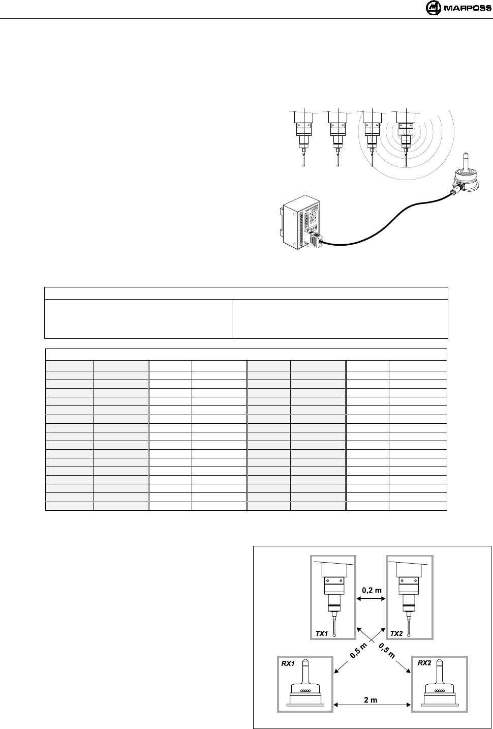
FRANÇAIS
E86N- Systeme touch a transmission radio
146
6. TRANSMISSION RADIO
6.1 Description
Le système de transmission radio est formé de trois éléments :
Emetteur : il émet les infos nécessaires à la CN pour le
traitement de la mesure.
Antenne : elle reçoit le signal de l’émetteur et l’envoie à l’unité
d’interface E86N.
Unité d’interface : elle traite les signaux et les convertit sous une
forme utilisable par la CN.
Le système E86N permet la programmation de 64 canaux de
transmission par le biais du clavier sur l’interface (voir chapitre 10
"PROGRAMMER LE SYSTEME” p. 159).
Pour augmenter le champ de transmission et la fiabilité de la
transmission radio, il est possible de relier deux antennes à l’unité
d’interface E86N.
Le système permet d’utiliser 4 émetteurs maximums sur une même
machine-outil (Figure 6-1), qui fonctionnent sur un même canal et qui
peuvent être activés, chacun à leur tour, grâce à un code identificateur
différent (voir rubrique 10.2 “Programmer l’émetteur" p. 163).
Figure 6-1. Système de transmission radio
Table 6-1. Caractéristiques techniques
-Distance de transmission : 15 m -Puissance d’activation : <10 mW
-Puissance de transmission : <1mW -Nbre de canaux de transmission : 64
-Distance d’activation, désactivation et
programmation
: 5 m -Fréquence de transmission :433,075÷434,775 Mhz
Table 6-2. Fréquences de transmission.
CANAL FRÉQUENCE CANAL FRÉQUENCE CANAL FRÉQUENCE CANAL FRÉQUENCE
1 433,075 17 433,475 33 434,000 49 434,400
2 433,100 18 433,500 34 434,025 50 434,425
3 433,125 19 433,525 35 434,050 51 434,450
4 433,150 20 433,550 36 434,075 52 434,475
5 433,175 21 433,575 37 434,100 53 434,500
6 433,200 22 433,600 38 434,125 54 434,525
7 433,225 23 433,625 39 434,150 55 434,550
8 433,250 24 433,650 40 434,175 56 434,575
9 433,275 25 433,675 41 434,200 57 434,600
10 433,300 26 433,700 42 434,225 58 434,625
11 433,325 26 433,725 43 434,250 59 434,650
12 433,350 28 433,750 44 434,275 60 434,675
13 433,375 29 433,775 45 434,300 61 434,700
14 433,400 30 433,800 46 434,325 62 434,725
15 433,425 31 433,825 47 434,350 63 434,750
16 433,450 32 433,850 48 434,375 64 434,775
6.1.1 Distances à respecter entre systèmes
Pour éviter le risque d’interférence entre systèmes situés à
proximité l’un de l’autre, vous devez respecter les distances
suivantes :
Au moins 2 mètres entre les antennes des systèmes
indépendamment de l’utilisation ou non de canaux adjacents
(ex. CH5 et CH6).
Au moins 0,2 mètre entre les émetteurs des systèmes,
indépendamment de l’utilisation ou non de canaux adjacents.
Au moins 0,5 mètre entre l’émetteur d’un système et
l’antenne d’un autre émetteur fonctionnant sur canaux
adjacents.
NOTA BENE:Si vous utilisez 2 systèmes sur une même
machine (ex. centres d’usinage à double
mandrin), Figure 6-2 mais utiliser aussi deux
canaux NON ADJACENTS et des codes
identificateurs “A” et “D”.
• La distance entre des systèmes opérant sur le même canal
doit être supérieure à 100 mètres.
Figure 6-2. Distances mini entre systèmes
ABCD
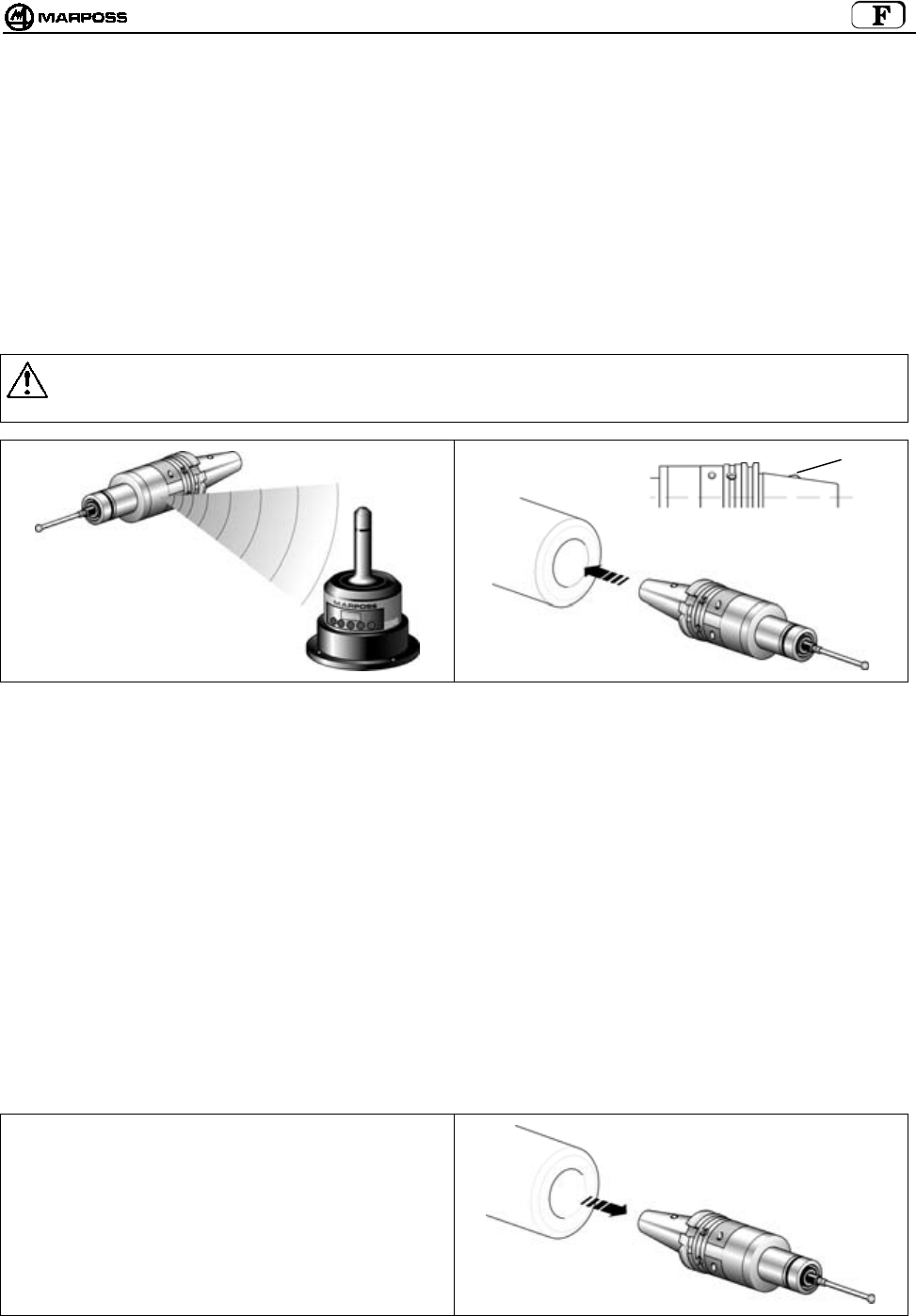
mida 147
6.2 Activer la transmission
L’émetteur est normalement dans une condition d’attente (stand-by); l’activation de la transmission peut avoir lieu de deux façons,
suivant la version de l’émetteur :
•activation radio
•activation mécanique (émetteur standard, uniquement)
6.2.1 Activation radio
Le système est activé quand l’antenne envoie un signal radio à l’émetteur. La commande d’activation du système (START) est générée
par l’unité d’interface de 2 façons :
par la liaison entre le signal d’entrée START/STOP et la logique de la machine (code M) ;
par le clavier, en maintenant la touche <select> pressée (pendant au moins 2 secondes).
6.2.2 Activation mécanique
Sur le cône porte-outils se trouve un microrupteur (H). L’introduction du cône dans le mandrin provoque l’activation de la transmission.
Mise en garde:
Quand vous rangez l’émetteur dans le magasin d’outils, assurrez-vous que le microrupteur qui active la transmission n’est pas
actionné.
Figure 6-3. Activation radio Figure 6-4. Activation mécanique
6.3 Désactiver la transmission
La désactivation de la transmission peut avoir lieu de plusieurs façons différentes suivant la version de l’émetteur.
6.3.1 Activation radio
DESACTIVATION RADIO :
1. Logique de machine
La désactivation a lieu par le biais de la commande machine sur l’entrée START/STOP (code M).
2. Depuis le clavier
par la pression de la touche <select> (pendant au moins 2 secondes)
DESACTIVATION AUTOMATIQUE
La désactivation a lieu quand le délai programmé sur le tempo de l’émetteur s’est écoulé
(voir rubrique 10.2 “Programmer l’émetteur" p. 163).
6.3.2 Activation mécanique
• DESACTIVATION MECANIQUE
La désactivation a lieu quand l’émetteur est extrait du
mandrin.
DESACTIVATION AUTOMATIQUE
La désactivation a lieu quand le délai programmé sur
le tempo de l’émetteur s’est écoulé (voir rubrique 10.2
“Programmer l’émetteur" p. 163).
Figure 6-5. Désactivation mécanique
H
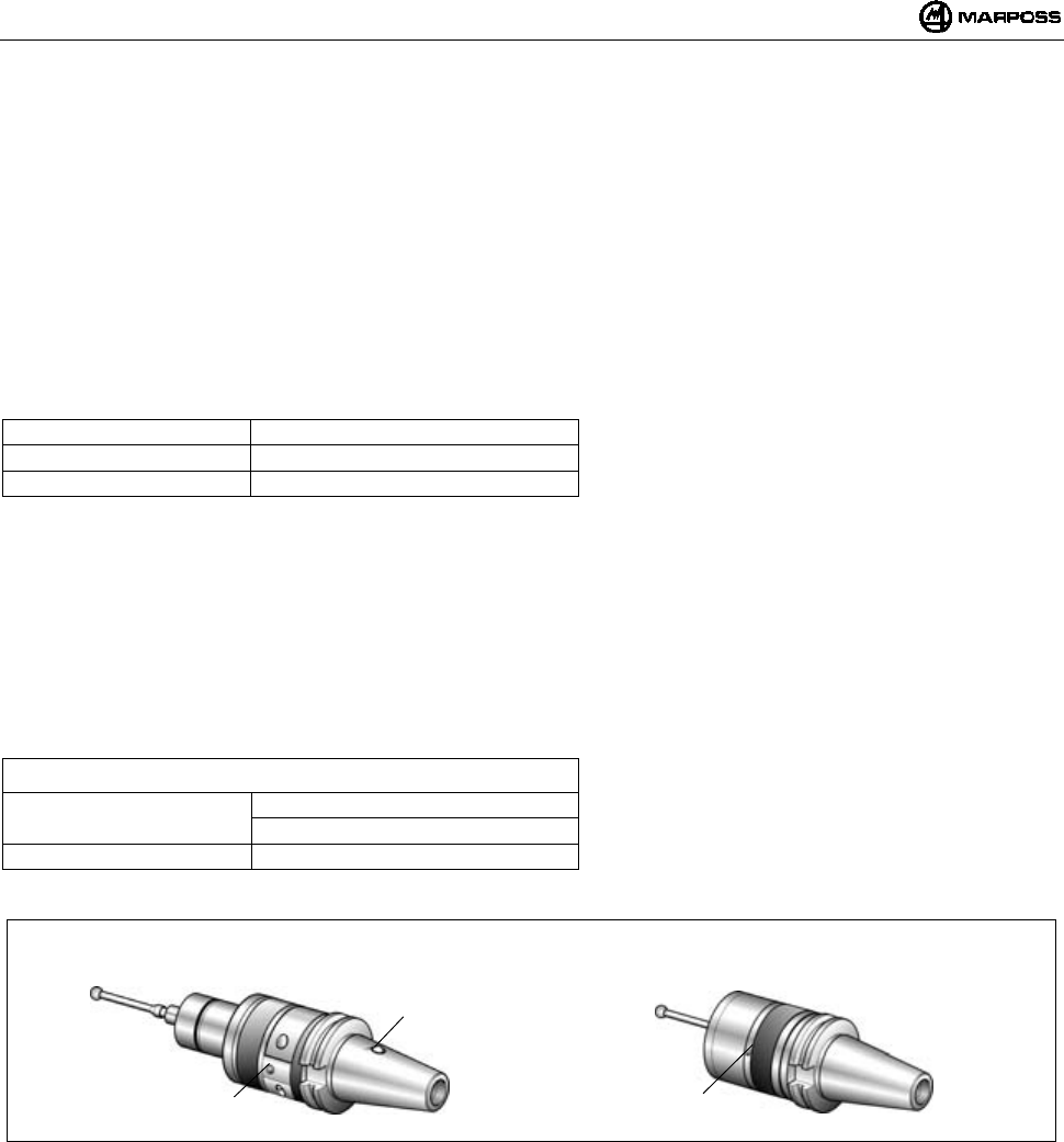
FRANÇAIS
E86N- Systeme touch a transmission radio
148
7. EMETTEUR E86N
7.1 Description
Il existe actuellement deux types d’émetteur :
• EMETTEUR STANDARD
sur lequel sont fixés les différents types de sonde, à l’aide d’une flasque
• EMETTEUR COMPACT
La sonde est contenue à l’intérieur de l’émetteur
L’émetteur envoie à l’antenne les informations suivantes, nécessaires à la CN pour le traitement de la mesure:
• Etat de la sonde : sonde avec stylet au repos/sonde avec stylet au travail
• Etat de la batterie : chargée ou presque à plat
Une LED verte (L) indique l’état de la sonde, de la batterie et de la transmission:
LED allumée en continu = Sonde avec stylet au travail
1 impulsion toutes les 2s = Transmission activée
2 impulsions toutes les 2s = Batterie presque à plat
Les émetteurs standard se répartissent à leur tour en:
• EMETTEURS A ACTIVATION RADIO:
La transmission est activée par un signal envoyé par l’antenne.
• EMETTEURS A ACTIVATION MECANIQUE:
La transmission est activée par le microrupteur (H), situé sur le cône porte-outils.
Le microrupteur n’est pas présent dans l’émetteur à activation radio.
ATTENTION: L’activation mécanique n’est prévue que sur les émetteurs standard et non sur les compacts.
Pour la programmation de l’émetteur, voir la rubrique 10.2 “Programmer l’émetteur" p. 163.
Table 7-1. Caractéristiques techniques
Alimentation : : 1 pile 9V (émetteur standard)
: 6 piles 1,5 V (émetteur compact)
Distance de transmission : 15m
Figure 7-1. Emetteurs.
H
Emetteur Standard Emetteur Compact
LL

mida 149
7.2 Durée de vie des piles
La charge de la pile de l’émetteur est signalée sur l’interface, par les LEDs correspondantes (Led Low Battery ou Led Error) mais aussi
sur l’afficheur (pressez la touche <select> pour afficher à gauche le code identificateur et à droite le niveau de charge (“7” valeur Maxi et
“0” batterie à plat). Plus précisément :
• La LED “Low battery” s’allume quand la pile atteint le niveau “3” sur l’afficheur
• La LED “Error” s’allume quand la pile atteint le niveau “0” sur l’afficheur
La valeur de la charge indiquée par l’afficheur reste mémorisée jusqu’à l’activation successive.
La durée de vie la pile dépend du temps d’utilisation de l’émetteur et du type de pile utilisée. La table ci-après reporte les valeurs de
durée en fonction de la pile et des conditions de fonctionnement de l’émetteur, en stand-by et en continu :
Emetteur standard
TYPE DE PILE PILE PRECONISEE FONCTIONNEMENT CONTINU FONCTIONNEMENT EN STAND-BY
Alcaline DURACELL MN1604
DURACELL PC1604 PROCELL
ENERGIZER X22
ENERGIZER 522
150 heures 170 jours
Lithium ENERGIZER L522
ULTRALIFE U9VL
DURACELL PL1604
SONNENSCHEIN SLM9-J
320 heures 380 jours
Nota bene: Vous trouverez dans le kit de l’émetteur une pile alcaline fournie par Marposs. Mettez la pile dans
l’émetteur avant le montage en machine (voir rubrique 15.1.2 “Inserimento/Sostituzione Batteria
Trasmettitore” p. 44).
Mise en garde :
EMETTEUR À ACTIVATION MECANIQUE
Vérifiez si le logement du cône dans le magasin d’outils a une forme qui permet d’éviter l’actionnement du
microrupteur (H) d’activation.
PILES AU LITHIUM : les piles au lithium peuvent exploser si elles ne sont pas remplacées correctement.
Remplacez-la uniquement par une pile identique ou équivalente (voir table). Mettez les piles usées à la
décharge conformément à la réglementation en vigueur.
é
Emetteur compact
TYPE DE PILE PILE PRECONISEE FONCTIONNEMENT CONTINU FONCTIONNEMENT EN STAND-BY
DURACELL MN9100
Alcaline
ENERGIZER E90
230 heures 250 jours
Nota bene: Vous trouverez dans le kit de l’émetteur des piles fournies par Marposs. Mettez les piles dans l’émetteur
avant le montage en machine (voir rubrique 15.1.2 “Installer/Remplacer la pile de l’émetteur” p. 176).

FRANÇAIS
E86N- Systeme touch a transmission radio
150
7.3 Dimensions émetteur avec sondes
7.3.1 Emetteur standard avec flasque standard
Figure 7-2. Dimensions hors tout émetteur avec flasque standard
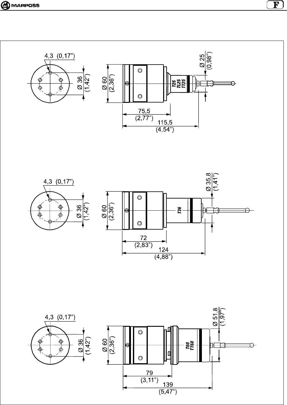
mida 151
7.3.2 Emetteur standard avec flasque réglable
Figure 7-3. Dimensions hors tout émetteur avec flasque réglable

FRANÇAIS
E86N- Systeme touch a transmission radio
152
7.4 Dimensions émetteur compact
7.4.1 Emetteur compact E86N-P
Figure 7-4
7.4.2 Emetteur compact E86N-P sans queue conique
Figure 7-5
3 VIS M4X6
3 VIS M4X6
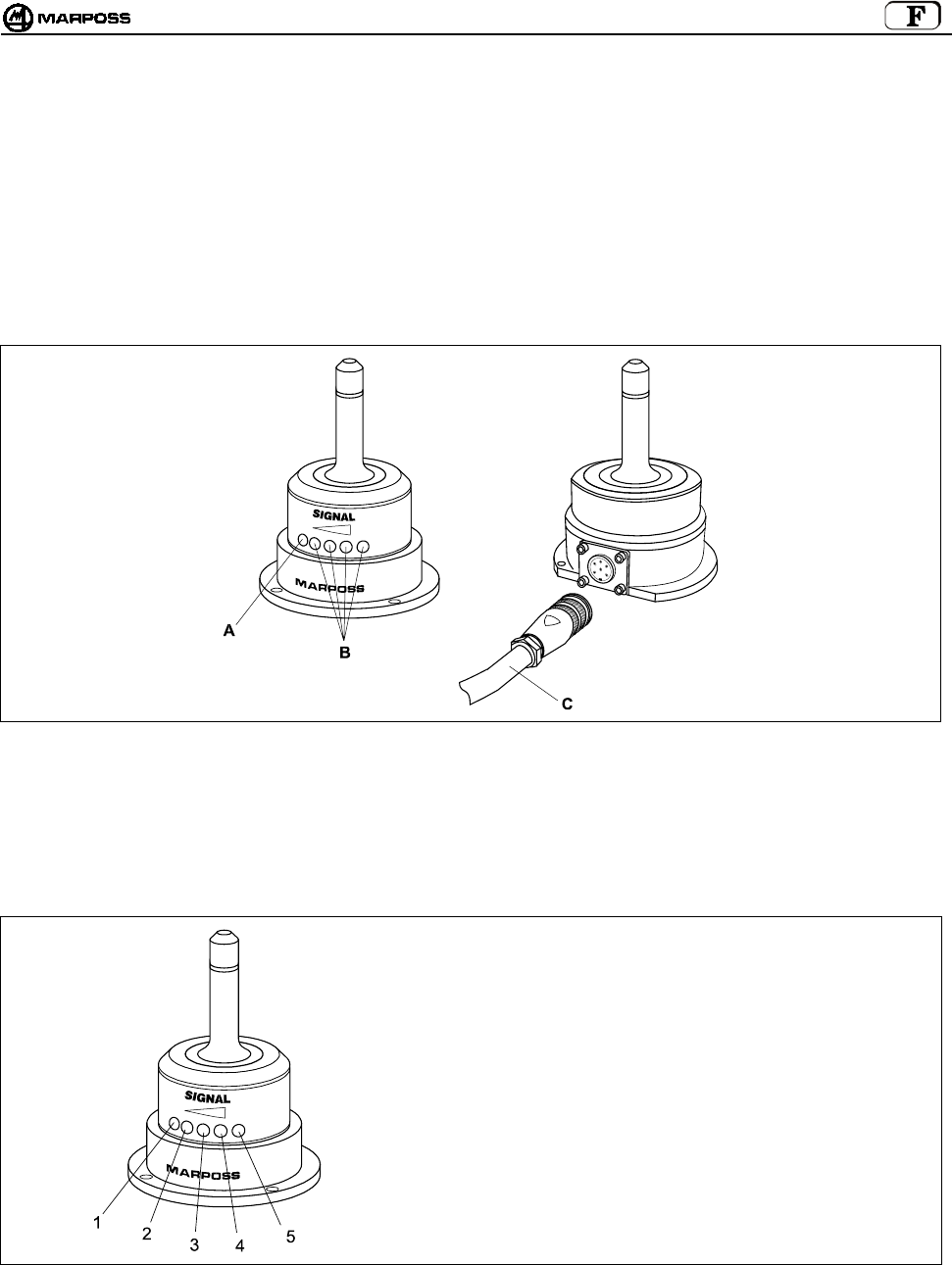
mida 153
8. RECEPTEUR E86N
8.1 Antenne et prolongateur avec connecteur
L'antenne reçoit les données émises par l’émetteur et les envoie à l’unité d’interface E86N à laquelle elle est reliée par un câble avec
connecteur.
Sur la partie avant de l’antenne se trouvent:
A- Une LED rouge. Allumée, elle indique qu’aucune transmission n’est en cours ou que le signal de l’émetteur n’a pas été reçu.
B- Une LED orange et trois LEDs vertes. Elles indiquent l’intensité du signal reçu. En s’allumant, ces LEDs facilitent le
positionnement de l’antenne au moment de l’installation.
C- Câble blindé avec connecteur (de 15ou 30 m de long) pour le raccordement à l’unité d’interface E86N.
Figure 8-1: Antenne et câble avec connecteur
8.2 Mode afficheur distant
Les LEDs présentes sur l’antenne peuvent également fonctionner comme “afficheur distant” de l’unité interface, si en phase de
programmation de l’interface, l’opérateur programme la donnée rd” (remote display) (voir rubrique 10.1 “Programmer l’interface” p.
160).
Dans ce cas, les LEDs prennent le sens suivant:
1 -
2 -
3 -
4 -
5 -
Led ROUGE= ERROR
Led ORANGE= LOW BAT
Led VERTE= toujours éteinte
Led VERTE= PROBE
Led VERTE= POWER
Figure 8-2. Fonctionnement de l’antenne comme indicateur distant de l’Unité d’interface.
8.3 Raccorder l’antenne
L'antenne doit être raccordée au bornier de l’unité d’interface E86N (voir schéma électrique, rubrique 9.4 "Raccorder l’unité d’interface”
L'antenne est fournie sans le câble avec connecteur.

FRANÇAIS
E86N- Systeme touch a transmission radio
154
8.4 Monter l'antenne
• L'antenne, qui a une base aimantée, peut être fixée provisoirement pour vous permettre de choisir la meilleure position. Vérifiez si
le signal émis par l’émetteur est reçu au cours des déplacements du système de détection.
• Pour le montage définitif, fixez l’antenne avec les quatre vis fournies dans le kit.
Figure 8-3
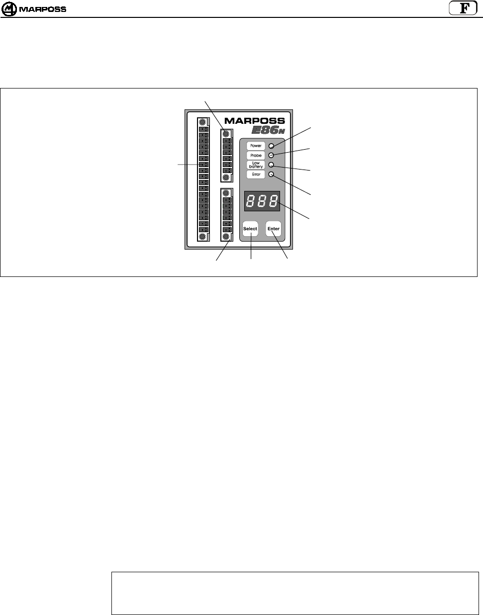
mida 155
9. UNITE D’INTERFACE E86N
9.1 Panneau frontal de l’unité d’interface
Figure9-1: Panneau frontal
A- LED “power” (verte) : allumée, elle indique la présence de tension.
B- LED “probe” (verte) : elle indique l’état de la sonde. Elle s’allume quand le stylet de la sonde est au travail et s’éteint
quand il est au repos.
C- LED “low battery”
(orange)
: allumée, elle indique que la pile est presque à plat. (voir rubrique 7.2 “Durée de vie des piles” p. 149
et signal de sortie LOW BAT rubrique 9.4 “Raccorder l’unité d’interface” p. 157).
D- LED “error” (rouge) : indique une condition d’erreur. Elle s’allume quand la transmission n’est pas activée, quand la sonde
est hors de portée du champ de transmission (voir également le signal de sortie ERROR rubrique
9.4 “Raccorder l’unité d’interface” p. 157) et quand la pile est complètement à plat (voir rubrique 7.2
“Durée de vie des piles” p. 149).
E- AFFICHEUR : afficheur à LEDs à trois chiffres et sept segments. Dans des conditions de fonctionnement normales,
il peut afficher le canal radio de fonctionnement, le code identificateur et l’état de charge de la pile.
En programmation, il indique toutes les valeurs programmables.
F-TOUCHE ENTER : Pressée plus de 2 secondes, elle permet d’accéder au mode de programmation.
En programmation, elle permet de valider la donnée sélectionnée et de passer à la suivante.
Pressée plus de 2 secondes simultanément à la touche <Select>, elle permet d’effacer les
messages d’alarme sur l’afficheur de l’interface.
G -TOUCHE SELECT :Pressée pendant au moins 2 secondes, elle permet l’affichage à gauche du code identificateur et à
droite du niveau de charge de la pile.
Pressée plus de 2 secondes, elle permet l’activation/désactivation manuelle du système.
Pressée plus de 2 secondes simultanément à la touche <Enter>, elle permet d’effacer les messages
d’alarme présents sur l’afficheur de l’interface.
En programmation, elle fait défiler les données programmables ou incrémente la donnée
courante.
H - BORNIER :pour le raccordement d’une seule l’antenne (H1) et pour la supplémentaire (H2).
ATTENTION
Si on utilise une seule antenne, pour un correct fonctionnement, il faut toujours la raccorder à la
borne inférieure H1. Si on la raccorde à la borne supérieure H2, le système ne fonctionne pas et sur
l’afficheur apparaît le message d’erreur “E.nb” (voir rubrique 14.1 “Messages d’erreur” p. 175).
I - BORNIER : Pour les raccordements électriques à la CN.
H2
E
G
C
D
I
F
H1
A
B

FRANÇAIS
E86N- Systeme touch a transmission radio
156
9.2 Dimensions de l’unité d’interface
Figure 9-2. Dimensions hors tout
9.3 Caractéristiques techniques Interface E86N
Alimentation : 24 VDC non stabilisée (13,5÷35 V)
: 300 mA max. (avec deux antennes reliées)
Signaux Entrée : Entrées optocouplées (24V - <10mA)
-AUX IN : Non relié (pour utilisations futures)
-SEL 0 - SEL 1 : Sélection code identificateur pour la sélection de 4 émetteurs maximum sur la même machine (voir
rubrique 9.4.1 “Sélectionner le code identificateur” p. 155).
24V - 7 mA
-START/STOP : Activation/Désactivation de la transmission.
24V – 4mA (High current)
La tension/courant nominale de cette entrée peut être programmée en fonction du type de CN relié (voir
rubrique 10.1 “Programmer l’interface” p. 160) sur les valeurs suivantes :
15V – 0,5 mA (Low current)
Nota bene: Le raccordement de signaux d’entrée peut être de type SINK (relier “COM” à “+24V”) ou de type SOURCE
(relier “COM” à “0V”).
Signaux Sortie : Contacts Relais à l’Etat Solide (SSR) 50V - 40 mA
-ERROR : Erreur de communication
(sonde non activée ou hors de la portée du champ de transmission, pile émetteur complètement plate
avec niveau pile sur afficheur égal à “0”.
Contact toujours N.F. (Normalement Fermé)
-AUX OUT : Non relié (pour utilisations futures)
-PROBE 1/SKIP : Signal relatif à l’état de la sonde utilisée ; il peut être programmé comme signal d’état sonde (au repos ou
au travail) ou SKIP (impulsion).
Contact programmable N.F. ou N.O. (Normalement Fermé ou Normalement Ouvert)
-PROBE 2/SKIP : Signal additionnel relatif à l’état de la sonde utilisée ; il peut être utilisé comme signal d’état sonde (au
repos ou au travail) ou SKIP (impulsion).
Contact programmable N.F. ou N.O. (Normalement Fermé ou Normalement Ouvert)
-LOW BAT : Signal de pile presque à plat avec niveau de batterie sur l’afficheur égal à “3”.
En utilisant une pile alcaline, le fonctionnement résiduel continu du système dans cette condition est le
suivant :
• 14 heures pour l’émetteur standard
• 24 heures pour l’émetteur compact
Contact programmable N.F. ou N.O. (Normalement Fermé ou Normalement Ouvert).
70
(2,76”)
51
(2,01”)
11
(0,43”)
68
(2,68”)
5,5
(0,22”)
90
(3,54”)
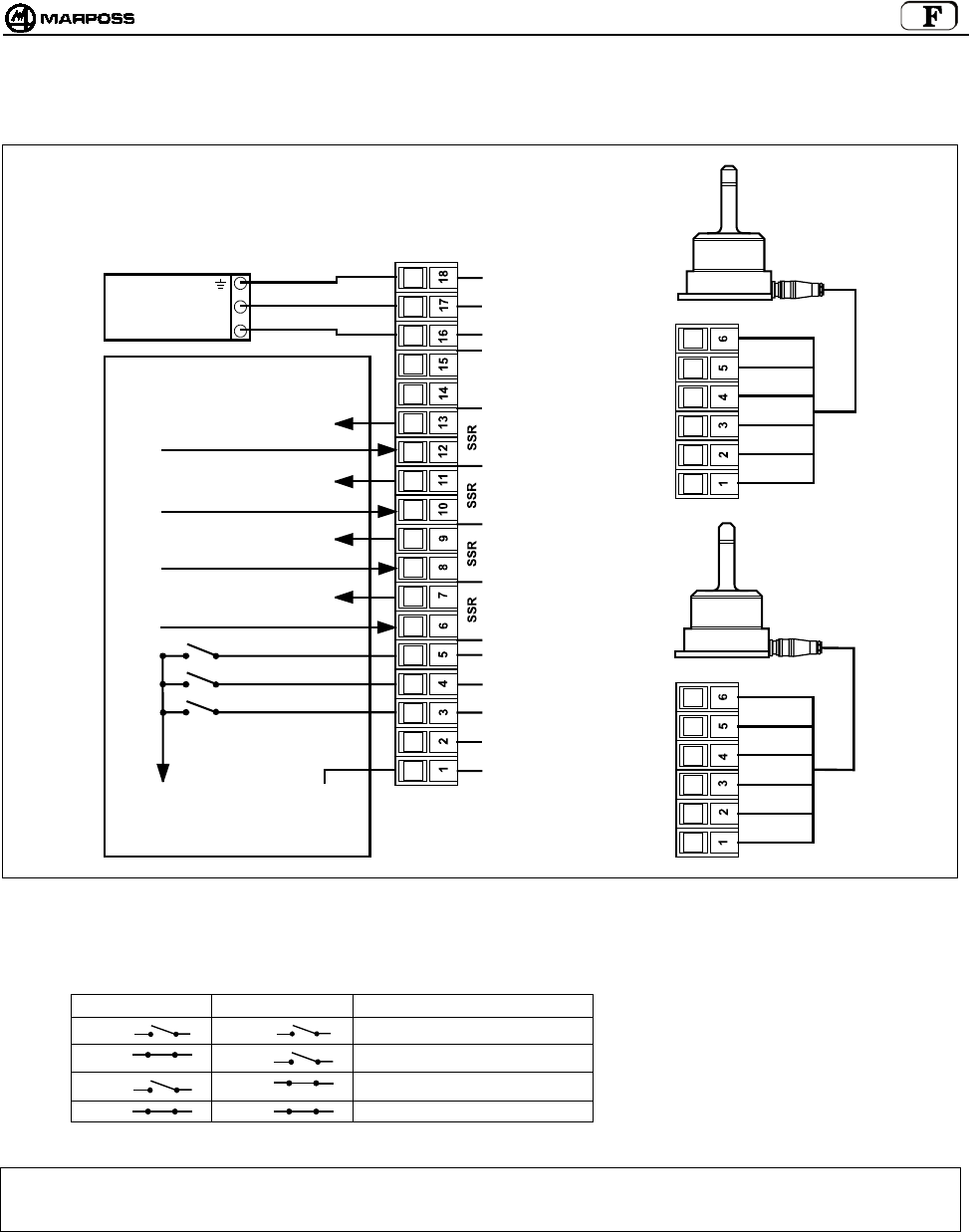
mida 157
9.4 Raccorder l’unité d’interface
Sur la carte de l’unité se trouve le bornier de raccordement ; les connexions sont effectuées par le biais de connecteurs à visser.
Figure 9-3. Connexions
9.4.1 Sélectionner le code identificateur
Entrée en provenance de la logique:
SEL 0 SEL 1 CODE IDENTIFICATEUR
I1 I2 A
I1 I2 B
I1 I2 C
I1 I2 D
Nota bene: Si vous utilisez un seul émetteur, IL N’EST PAS NECESSAIRE de gérer ces 2 entrées en provenance de la CN. Par
défaut, l’interface est programmée sur le code identificateur A, tout comme l’est l’émetteur (voir rubrique 10.2
“Programmer l’émetteur” p. 163).
ANTENNE 1
ANTENNE 2
VERT
BLEU
BLANC
VIOLET
BLINDAGE
ROUGE
VERT
BLEU
BLANC
VIOLET
BLINDAGE
ROUGE
COM
A
UX IN
SEL 0
SEL 1
START/STOP
ETAT SONDE 1
SKIP
ETAT SONDE 2
SKIP
PILE A
PLAT
ERREUR
A
UX OUT
+24V DC
0V
TERRE
CN CONTROLE MACHINE
0V SOURCE
24V SINK
ETAT SONDE 1/ SKIP
ETAT SONDE 2/ SKIP
PILE A PLAT
ERREUR
24V
0V
UNITA’ DI
ALIMENT.
I1
I2
24V SOURCE
0V SINK
(
H1
)
(
H2
)
(
I
)
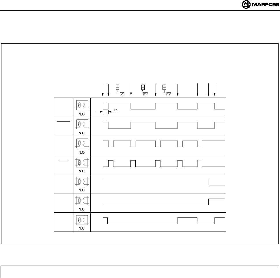
FRANÇAIS
E86N- Systeme touch a transmission radio
158
9.5 Diagramme des E/S unité d’interface E86N
Figure 9-4. Diagramme E/S unité d’interface
NOTA BENE: Dans certains milieux de travail, particulièrement exposés aux interférences électromagnétiques, le temps
nécessaire pour activer la transmission peut être plus qu’une seconde (max 6).
Ouvert
Fermé
Ouvert
Fermé
Ouvert
Fermé
Ouvert
Fermé
Ouvert
Fermé
Ouvert
Fermé
Ouvert
Fermé
Etat
Sonde
Etat
Sonde
Skip
Skip
Pile à
p
lat
Pile à
p
lat
Erreur
Signaux
E86N
relais
état
solide
Start
Sonde activée
A
u repos
Ouverture contact
A
u travail
Fermeture contact
A
u repos
Erreu
r
Erreur éliminée
Pile à plat
Sonde désactivée
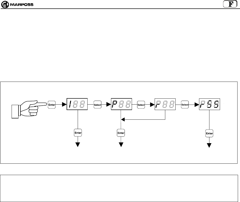
mida 159
10. PROGRAMMER LE SYSTEME
Maintenez la touche pressée “Enter” pendant plus de 2 secondes : le système entre dans le mode programmation. Choisissez le type
de programmation souhaitée avec la touche “Select”:
I --> Programmation de l’Interface
P --> Programmation de l’Emetteur
r --> Programmation de l’Emetteur dans le mode "Recovery"
rSS ÆProgrammation de la fonction “Sniffer”
Le choix terminé, avec les touches “Select” et “Enter”, modifiez les données de programmation. La touche “Select” incrémente la
donnée de programmation courante tandis que la touche “Enter” permet de la valider et de passer à la suivante.
ATTENTION: Si vous souhaitez reprogrammer uniquement le Canal de fonctionnement, commencez la procédure en partant de
la programmation de l’émetteur.
De cette façon, étant donné que l’interface est fournie avec la fonction Programmation automatique du canal activée
(AP=1 – voir rubrique 10.1 “Programmer l’interface”), à la fin de la reprogrammation du canal de fonctionnement sur
l’émetteur, l’interface est automatiquement programmée sur le même canal.
PROGRAMMER
L’EMETTEUIR
PROGRAMMER
L’INTERFACE
PROGRAMMER
L’EMETTEUR DANS L
E
MODE RECOVERY
> 2 secondes
PROGRAMMATION DE LA
FONCTION “SNIFFER”
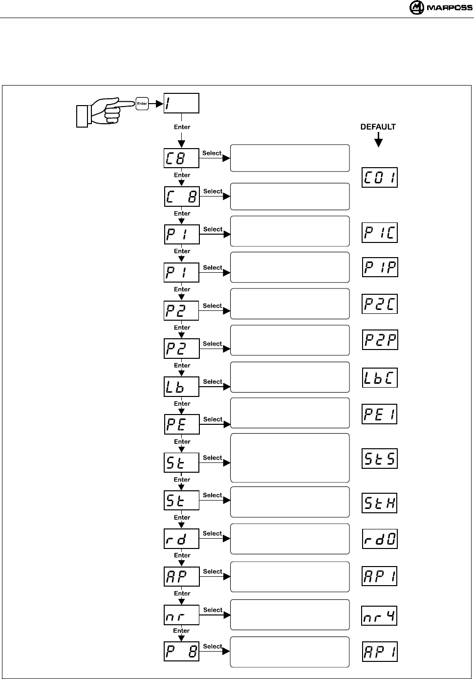
FRANÇAIS
E86N- Systeme touch a transmission radio
160
10.1 Programmer l’interface
En entrant dans le mode de programmation et en sélectionnant le type de programmation "I", avec les touches “Select” et “Enter”, vous
pouvez modifier les valeurs suivantes, une par une :
Nota bene: A la validation de la dernière donnée, vous quittez la programmation. Vous pouvez toutefois quitter la programmation à
tout moment et annuler la séquence, en maintenant pressé pendant plus de 2 secondes la touche <ENTER>.
Saisie des canaux :
DIZAINES
Saisie de canaux :
UNITES
Polarité sortie probe 1:
P1C= SORTIE N.F.
P1O= SORTIE N.O.
Fonctionnalité sortie probe 1:
P1P= PROBE STATUS
P1S= SKIP
Mode sortie LOW BAT:
LbC= N.F.
LbO= N.O.
Sortie PROBE en erreur :
PE0= Probe à 0 (repos)
PE1= Probe à 1(travail)
Signal START:
S= Standard
P= Pulse
r= retrigger
A
fficheur distant sur poste base :
0= désactivé
1= activé
Entrée START:
L= basse tension 15V-0,5mA
H= courant normal 24V-4mA
Progr. automatique canal:
0= désactivée
1= activée
Valider programmation :
0= non validée
1= validée
Polarité sortie probe 2:
P2C= SORTIE N.F.
P2O= SORTIE N.O.
Fonctionnalité sortie probe 2:
P2P= PROBE STATUS
P2S= SKIP
> 2 secondes
Nombre de tentatives
d’activation/désactivation
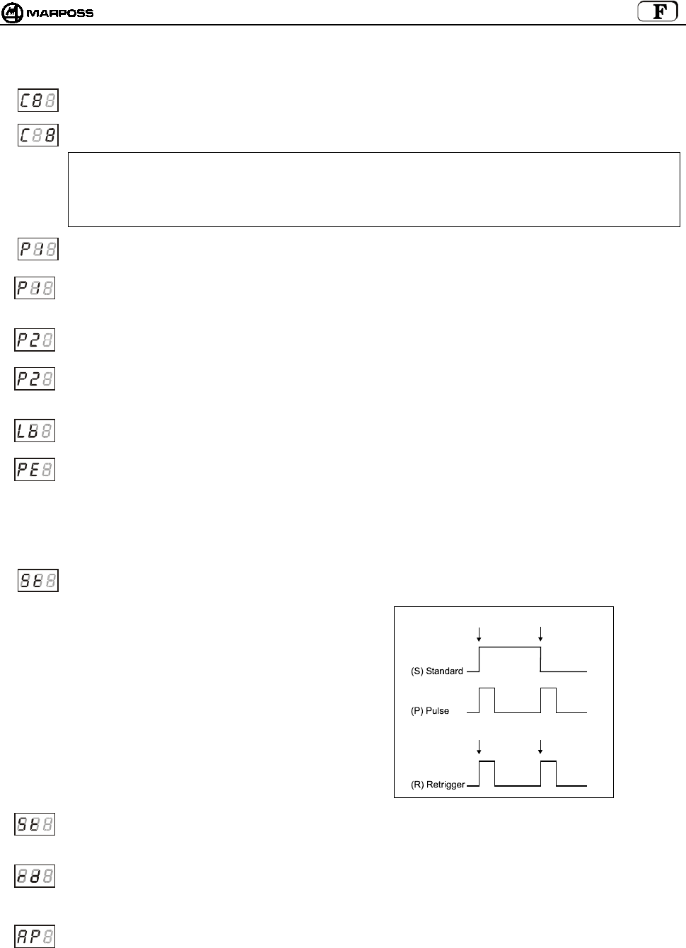
mida 161
Voici la description détaillée des données de programmation de l’interface :
Canal de transmission de l’interface – dizaines : le champ Dizaines, qui est incrémenté en boucle par le bouton
“Select”, clignote.
Canal de transmission de l’interface – unités: le champ Unités, qui est incrémenté en boucle par le bouton “Select”,
clignote.
ATTENTION :
Après avoir validé la programmation (P1), si vous avez par erreur sélectionné les canaux 65-69 ou 00, le système
considère la programmation comme non valide et le canal sélectionné par erreur clignote sur l’afficheur de l’interface.
Pour quitter cette condition, il suffit de retourner dans le mode programmation de l’interface et sélectionner le canal
correct (de 1 à 64).
Polarité de la sortie PROBE1: les premiers caractères sont “P1”. Le troisième prend tour à tour les valeurs <C> et
<O> pour indiquer NORMALEMENT FERME et NORMALEMENT OUVERT.
Fonctionnalité de la sortie PROBE1: les premiers caractères sont “P1”. Le troisième prend tour à tour les valeurs ‘P’
et ‘S’ pour indiquer une sortie normale ou de type “skip” (impulsion de la durée de 44ms à chaque variation de l’état de
la sonde touch).
Polarité de la sortie PROBE2: les premiers caractères sont “P2”. Le troisième prend tour à tour les valeurs <C> et <O>
pour indiquer NORMALEMENT FERME et NORMALEMENT OUVERT.
Fonctionnalité de la sortie PROBE2: les premiers caractères sont “P2”. Le troisième prend tour à tour les valeurs <P>
et <S> pour indiquer la sortie normale ou de type “skip” (impulsion de la durée de 44ms à chaque variation de l’état de
la sonde touch)
Polarité de la sortie LOW_BAT: les premiers caractères sont “lb” Le troisième prend tour à tour les valeurs <C> et
<O> pour indiquer normalement fermé et normalement ouvert.
Sortie Probe en erreur: permet de programmer l’état que prennent les sorties PROBE1 et PROBE2 dans des
conditions d’erreur :
- l’émetteur n’est pas activé
- l’émetteur est hors champ
- la pile est complètement à plat
Les premiers caractères sont “PE”. Le troisième prend tour à tour les valeurs <0> (probe au repos) et <1> (probe au
travail).
Mode de fonctionnement du signal Start: les premiers caractères sont “St”. Le troisième prend tour à tour les valeurs
‘S’ (standard), ‘P’ (Pulse) et ‘r’ (retrigger).
Dans le mode “standard”, le front de
montée active la sonde et le front de
descente la désactive.
Dans le mode “pulse”, le front de montée
fait changer l’état de la sonde ; si elle est
désactivée, elle s’active et si elle est
activée, elle se désactive.
Dans le mode “retrigger”, il est impossible
de désactiver la sonde via radio. Un front
de montée sur le signal Start, quand la
sonde est encore active, provoque le
retrigger du tempo de l’émetteur. Dans ce
mode, l’émetteur peut être éteint
uniquement par le temporisateur.
Courant de l’entrée Start: les premiers caractères sont “St”. Le troisième prend tour à tour les valeurs ‘L’ (Low current)
et ‘H’ (High current). Dans le mode “low current”, l’entrée absorbe environ 0,5mA à 15V (*Note). Dans le mode “high
current”, l’entrée est standard et absorbe environ 4mA à 24V.
Afficheur distant Antenne : les premiers caractères sont “rd”. Le troisième prend tour à tour les valeurs <0> (afficheur
désactivé, les LEDs du poste de base indiquent le niveau du signal radio) et <1> (afficheur, les LEDs du poste de base
reportent l’indication des LEDs sur l’interface, à l’exception de la LED verte centrale du poste de base qui est toujours
éteinte) (voir 8.2 “Mode afficheur distant” p. 153).
Programmation automatique du canal de l’interface : les premiers caractères sont “AP”. Le troisième prend tour à
tour les valeurs <0> (désactivée, la programmation du canal de l’émetteur n’a aucun effet sur la valeur programmée de
l’interface) et <1> (activée, à la fin de la programmation de l’émetteur, le canal de l’interface est aligné sur le canal que
l’on programme sur l’émetteur (voir rubrique 10.2 ”Programmer l’émetteur” p. 163).
*Note: Cette fonction est habilitè e par l’utilization de la rollonge code.6739696319.
Activation
Activation
Désactivation
Retrigge
r

FRANÇAIS
E86N- Systeme touch a transmission radio
162
Nombre de tentatives d’activation /désactivation : les deux premiers caractères correspondent à l’abréviation “nr”.
le troisième prend cycliquement les valeurs de 2 à 9 (la valeur par défaut étant 4).
cette donnée permet de programmer le nombre maximum de tentatives que le poste de base effectue pour
l’activation/désactivation de l’émetteur ; quand le nombre de tentatives est atteint, si l’émetteur ne s’est pas
activé/désactivé, il faut donner à l’interface une nouvelle commande avec le signal de start.
l’augmentation du nombre de tentatives entraîne un temps de retard plus long pour l’activation/désactivation.
pour la valeur par défaut (nr=4), les temps d’activation/désactivation sont les suivants :
TYPIQUE VALEUR MAX CODE IDENTIFICATION
1,050 s 4,200 s A
1,200 s 4,800 s B
1,350 s 5,400 s C
1,500 s 6,000 s D
quand le nombre de tentatives varie, les valeurs dans la table se modifient suivant la formule :
delay = default delay x (nr / 4)
comme la table l’indique, le temps d’activation/désactivation dépend également du code d’identification utilisé (sous-
canal).
plus la distance entre les codes est grande, plus la probabilité d’échec d’activation/désactivation est petite, dans des
situations où les applications à proximité sont particulièrement nombreuses.
Validation des données programmées : le premier caractère est “P”. Le troisième prend tour à tour les valeurs <0>
pour ne pas programmer l’interface et <1> pour la programmer.

mida 163
10.2 Programmer l’émetteur
En entrant dans le mode de programmation et en sélectionnant le type de programmation "P", avec les touches “Select” et “Enter”, vous
pouvez modifier une des valeurs suivantes :
Nota bene: Après la validation de la dernière donnée, vous quittez la programmation et l’émetteur est désactivé. Vous pouvez
toutefois quitter la programmation à tout moment et annuler la séquence, en maintenant pressée pendant plus de 2
secondes la touche <ENTER>.
(
∗
) Nota bene: dépend du type d’émetteur :
- dans le cas d’un émetteur à activation radio, le paramètre mode d’activation sera sur activation radio et la durée
de l’éteignement sur la valeur <5> qui correspond à 2'14".
- dans le cas d’une activation mécanique, le paramètre mode d’activation sera sur activation mécanique et la durée
de l’éteignement sur la valeur <8> qui correspond à un temps infini.
Saisie des canaux:
DIZAINES
Saisie des canaux:
UNITES
Code identificateur :
(A, B, C, D)
Mode activation:
0= Radio
1= Mécani
q
ue
Durée de fonctionnement:
0= 4"
1= 8"
2= 17"
3= 34"
4= 1'7"
5= 2'14"
6= 4'28"
7= 8'57"
8=
∞
Retrigger du Tempo:
0= Désactivé
1= Activé
Valider programmation :
0= non validée
1= validée
> 2 secondes
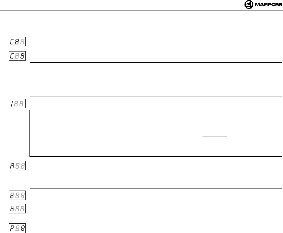
FRANÇAIS
E86N- Systeme touch a transmission radio
164
Voici la description détaillée des données de programmation de l’émetteur :
Canal de transmission – dizaines :
: le champ Dizaines, qui est incrémenté en boucle de la valeur <0> à la valeur <6> clignote.
Canal de transmission – unités : le champ Unités, qui passe, en boucle, de la valeur <0> à la valeur <9>, clignote.
ATTENTION :
Après avoir validé la programmation (P1), si vous avez par erreur sélectionné les canaux 65-69 ou 00, le système
considère la programmation comme non valide et le canal sélectionné par erreur clignote sur l’afficheur de l’interface.
L’émetteur peut être réinitialiser uniquement dans le mode “recovery” (voir 10.3 “Programmer l’émetteur dans le mode
Recovery” p. 165).
Code identificateur : le premier caractère est “I”. Le second peut être sélectionné parmi les valeurs <A, B, C, D>.
ATTENTION:
Le numéro du canal utilisé et le code identificateur (ex. 12B) permettent d’identifier sans erreur un émetteur.
Etant donné que le code identificateur peut être programmé pour l’émetteur mais est une entrée de logique externe
(CN) pour l’interface, il est recommandé de modifier ce paramètre sur l’émetteur uniquement si vous êtes sûr qu’il est
identique à celui de l’interface ; sinon, le système ne fonctionnera pas à cause d’un manque de communication.
L’unique façon de le rétablir est de faire une procédure de programmation de l’émetteur dans le mode “Recovery” (voir
rubrique 10.3 “Programmer l’émetteur dans le mode Recovery” p. 165).
Mode d’activation : le premier caractère est “A” Le troisième prend en boucle les valeurs <0> pour activation radio et
<1> pour activation mécanique ;
ATTENTION :
Laissez la valeur par défaut, reportée page précédente.
Durée de fonctionnement : le premier caractère est “t”. Le troisième doit être paramétré avec une valeur comprise
entre <0 et 8>, correspondant à une durée de fonctionnement qui va d’un minimum de 4” (valeur 0) à l’infini (valeur 8).
Retrigger du temporisateur : le premier caractère est “r”. Le troisième prend, en boucle, les valeurs <0> pour retrigger
désactivé et <1> pour retrigger activé.
Cette donnée permet la mise à zéro du temporisateur après une variation d’état de la sonde.
Valider les données programmées. Le premier caractère est “P”. Le troisième prend en boucle les valeurs <0> pour
ne pas programmer l’émetteur et <1> pour le programmer.
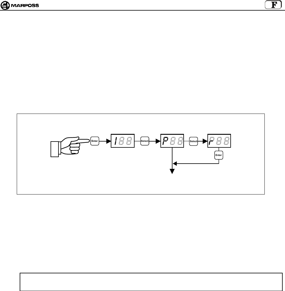
mida 165
10.3 Programmer l’émetteur dans le mode Recovery
Si vous vous trouvez dans une des conditions suivantes pour l’émetteur :
a. canal de transmission de l’émetteur inconnu
b. programmation erronée du canal de transmission (ex. 65-69 ou 00)
c. programmation erronée du code identificateur (autre que celui de l’interface)
nous avons prévu une procédure de programmation de l’émetteur appelée “recovery”, qui permet de remonter aux paramètres de
l’émetteur et, le cas échéant, de les modifier.
Cette procédure s’effectue comme suit :
1. l’interface sous tension, coupez l’alimentation en énergie électrique de l’émetteur (dévissez le couvercle des piles de l’émetteur
à activation radio ou ouvrez le microrupteur sur le cône dans le cas d’un émetteur à activation mécanique) ;
2. depuis l’interface, accédez au mode de programmation et sélectionnez le type de programmation "r";
3. pressez la touche <TER> sur l’afficheur pour visualiser le message "REC";
4. pliez le stylet (position de travail) et maintenez-le ainsi tout en remettant l’émetteur sous tension (fermez le couvercle des piles
de l’émetteur à activation radio ou fermez le microrupteur sur le cône dans le cas d’un émetteur à activation mécanique) ;
5. l’émetteur est activé sur un canal de service, au lieu d’un canal programmé et sur l’afficheur de l’interface, le message “REC”
disparaît pour laisser la place au numéro du canal (les dizaines clignotent) sur lequel l’émetteur était programmé ;
6. relâchez le stylet en maintenant l’émetteur sous tension (couvercle fermé/microrupteur sur le cône fermé).
A ce stade, après avoir obtenu l’info souhaitée, vous pouvez
• quitter la programmation
en maintenant pressé pendant plus de 2 secondes la touche <ENTER> ou simplement en relâchant le couvercle/microrupteur.
• effectuer une programmation normale de l’émetteur comme l’indique la rubrique 10.2 ”Programmer l’émetteur” p. 163.
ATTENTION : Si la “programmation automatique du canal” (AP = 1 – voir rubrique 10.1 “Programmer l’interface”), est
activée dans l’interface, à la fin de la programmation de l’émetteur, le canal de l’interface change aussi et
s’aligne sur celui présent sur l’émetteur même.
> 2 secondes
PROGRAMMER
L’EMETTEUR
(voir rubrique 10.2)

FRANÇAIS
E86N- Systeme touch a transmission radio
166
10.4 Analyse occupation du spectre électromagnétique (fonction “Sniffer”)
L’analyse de l’occupation du spectre électromagnétique comprend deux phases:
• Balayage
L’interface E86N exécute cycliquement le balayage des 64 canaux, en mémorisant pour chaque canal l’amplitude maximale du
signal reçu ;
• Affichage des résultats
L’interface E86N affiche les canaux et l’amplitude maximale mémorisée au balayage précédent.
Pour activer la fonction, mettre l’interface dans le “Mode Programmation” (en appuyant sur “Enter” pendant au moins 2 secondes),
appuyer plusieurs fois sur la touche “Select” pour faire apparaître sur l’afficheur le code “rSS” puis valider avec “Enter”.
XX XX XX XX
> 2 secondes
> 2 secondes > 2 secondes > 2 secondes > 2 secondes
Enter=Liste ▲
Select= Liste ▼
Enter=Liste ▲
Select= Liste ▼
Enter=Liste ▲
Select= Liste ▼
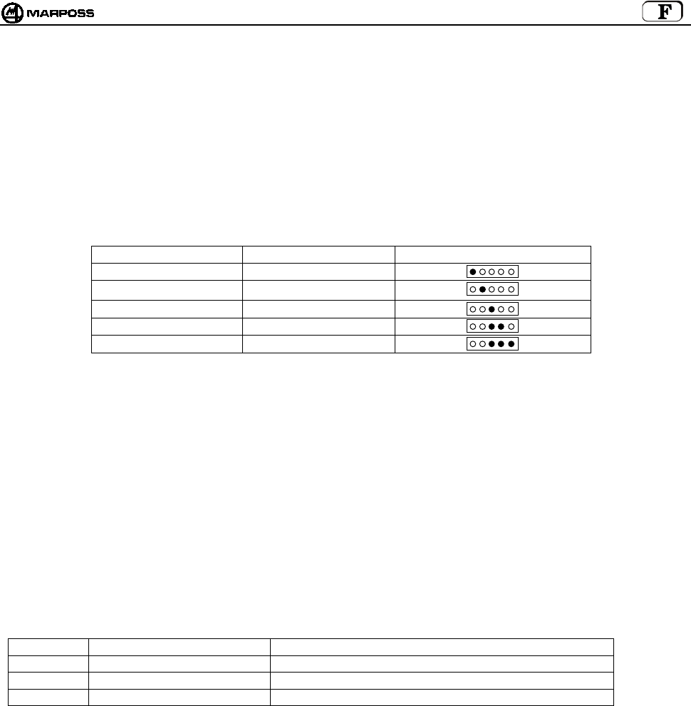
mida 167
10.4.1 Balayage
Appuyer sur “Select” pour faire apparaître “St” (Start) sur l’afficheur.
Valider avec “Enter” pour activer le balayage. Pour stopper le balayage, appuyer à nouveau sur la touche “Enter” pendant au moins 2
secondes.
Le balayage peut être activé pendant une longue période.
Pendant le balayage, la touche “Select” n’est pas active.
Sur l’afficheur apparaît en séquence :
• le nombre du canal acquis “Cnn” (nn= numéro du canal 01-64, en plus du canal d’activation “CA”)
• l’amplitude correspondante du signal “XX”.
L’amplitude du signal est exprimée dans l’échelle logarithmique et peut varier de –9 à 99 (voir la table ci-dessous).
NIVEAU SIGNAL VALEUR AFFICHEE LED POSTE BASE
sous la seuil ≤ -1
tres bas (1) 0 / 3
bas 4 / 7
milieu 8 / 11
haut ≥ 12
NOTE:
1. La valeur <0> correspond au niveau de signal minimum considéré “compréhensible” (Amplitude –102dBm et rapport
Signal/Bruit > -12dB).
2. Quand la fonction de balayage est active, toutes les autres fonctions sont désactivées. (L’état des sorties de E86N est dans
une condition semblable à celle d’erreur).
3. Les valeurs maxi acquises sont mémorisées dans une mémoire non rétentrice : elles sont donc perdues à la mise hors tension
de l’appareil.
4. Quand on active un balayage, les valeurs précédemment acquises sont effacées.
5. La durée du balayage est d’environ 1 seconde par canal et donc un balayage complet requiert environ 70 secondes. Etant
donné que le système est en mesure d’acquérir un seul canal à la fois, la probabilité d’identifier des signaux
électromagnétiques de courte durée augmente plus la période d’observation est longue.
6. Les valeurs acquises sont rendues disponibles uniquement après avoir effectué au moins un balayage complet.
7. Si les postes de base sont deux, des deux données acquises, celle qui sera utilisée sera la plus grande.
10.4.2 Affichage des résultats
Les résultats d’un balayage peuvent être affichés dans trois ordres différents :
Symbole Ordre Premier élément de la liste
HI Signal reçu décroissant Canal sur lequel le signal d’amplitude maxi a été reçu
LO Signal reçu croissant Canal sur lequel le signal d’amplitude mini a été reçu
CH Numéro canal croissant Canal 00
Pour afficher les résultats, appuyer sur “Select” pour faire apparaître sur l’afficheur le symbole correspondant à l’ordre souhaité puis
presser la touche “Enter”.
Sur l’afficheur, c’est le numéro du canal qui apparaît d’abord suivi de la valeur du signal.
• Appuyer sur la touche “Enter” pour passer à l’élément de la liste suivant et atteindre le dernier élément.
• Appuyer sur la touche “Select” pour retourner à l’élément précédent et atteindre le premier élément.
• Appuyer sur la touche “Enter” pendant au moins 2 secondes pour quitter le balayage de la liste.
Rouge
Orange
Ver
t
Verts
Verts
i

FRANÇAIS
E86N- Systeme touch a transmission radio
168
11. MONTER LA SONDE – EMETTEUR STANDARD
11.1 Monter la sonde – émetteur standard
Pour monter ou démonter la sonde de l’émetteur, procédez comme suit :
Mise en garde:
En phase de montage de la sonde, assurez-vous que les joints d’étanchéité sont en excellent état et bien mis dans leur
logement.
SONDE T25/TL25/TT25
- vissez la flasque (A) sur l’émetteur, avec la clé prévue à cet effet (A1).
- vissez la sonde sur la flasque (A) avec la clé fournie par Marposs (A2).
SONDE T36
- fixez la sonde sur la flasque (B) avec les vis (B1) ;
- vissez la flasque (B) sur l’émetteur avec la clé fournie par Marposs.
SONDE T60/TT60
- fixez la sonde sur la flasque (C) avec les vis (C1) ;
- vissez la flasque (C) sur l’émetteur avec la clé fournie par Marposs ;
Mise en garde :
L’opération terminée, effectuez l’alignement du système.
Figure 11-1
A
2
A
T25/TL25/TT25
B1
B
T36
C1 C
T60/TT60
A
1
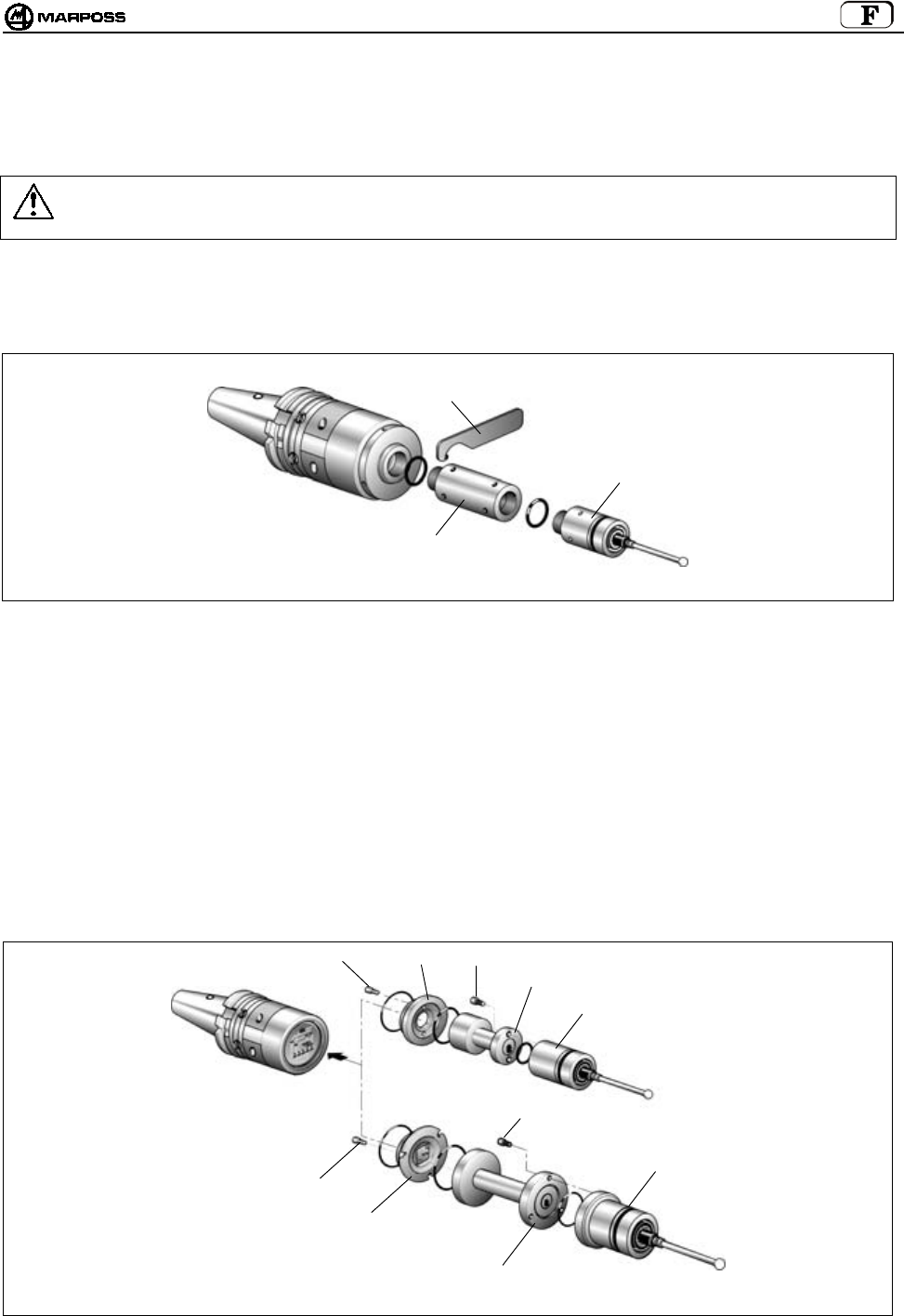
mida 169
11.2 Installer un prolongateur pour sondes (optionnel)
Le prolongateur doit être installé entre la sonde et l’émetteur pour augmenter la profondeur de mesure du système. Pour installer le
prolongateur, procédez comme suit.
Mise en garde :
Avant d’installer le prolongateur, vérifiez tout d’abord si les joints d’étanchéité sont en bon état et bien mis dans leur
logement.
• Prolongateur pour sonde T25/TL25/TT25
- Déposez la sonde de l’émetteur avec la clé (A1) fournie par Marposs.
- Placez le prolongateur (A2) avec ses joints d’étanchéité entre la sonde et l’émetteur.
- Serrez le tout avec la clé (A1).
Figure 11-2
• Prolongateur pour sonde T36
- Dévissez la flasque (B) sur l’émetteur.
- Déposez la sonde de la flasque (B) en retirant les vis (B1).
- Fixez le prolongateur (B2) sur la flasque (B) avec les vis (B1).
- Vissez le groupe flasque/prolongateur sur l’émetteur avec la clé fournie par Marposs.
- Fixez la sonde au prolongateur avec les vis (B3).
• Prolongateur pour sonde T60/TT60
- Dévissez la flasque (C) sur l’émetteur.
- Déposez la sonde de la flasque (C) en retirant les vis (C1).
- Fixez le prolongateur (C2) sur la flasque (C) avec les vis (C1).
- Vissez le groupe flasque/prolongateur sur l’émetteur avec la clé fournie par Marposs.
- Fixez la sonde au prolongateur avec les vis (C3).
Figure 11-3
A
2
A
1
T25/TL25/TT25
T60/TT60
BB3
B2
C1
C
C2
B1
T36
C3

FRANÇAIS
E86N- Systeme touch a transmission radio
170
12. MONTER L’EMETTEUR
12.1 Monter l’émetteur standard sur le cône
- Déposez les couvercles de la pile (C) de l’émetteur - vis (D) – pour accéder aux quatre orifices (E) sur la flasque. La fixation à la
flasque standard peut avoir lieu de deux façons différentes :
- Pratiquez sur le cône quatre orifices filetés M4x8 (A) et un fraisage central (B) comme l’indique la Figure 12-1.
- Introduisez, entre l’émetteur et le cône, la sphère(G) ø 6 mm fournie dans le kit.
- Fixez l’émetteur au cône avec les quatre vis (F).
Alignement du système
- Montez le stylet de la sonde (voir "Monter le stylet de la sonde").
- Alignez le centre de la sphère du stylet sur l’axe du cône avec les quatre vis (F).
- Le système aligné, serrez les quatre vis cruciformes (F) .
Figure 12-1
D
C
D
C
F
E
F
34
(1,34”)
34
(1,34”)
4,5
±
0,1 mm
(0,177 ± 0,004)
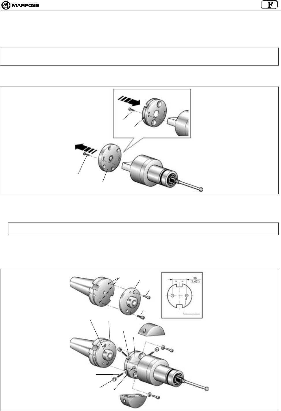
mida 171
12.2 Monter l’émetteur standard sur le cône avec flasque réglable
1. Retirez les vis pour déposer les couvercles de la pile de l’émetteur (voir rubr.12.1).
Nota
bene:
Les opérations décrites aux points 2 - 3 - 4 et 5 concernent uniquement l’émetteur à activation radio. L’émetteur à
activation mécanique (microrupteur sur le cône) est fourni avec le cône porte-outils et les flasques de réglage
montées. Dans ce cas, passez directement au point 6.
2. Retirez les quatre vis (D) pour déposer la flasque standard (C) de l’émetteur.
3. Fixez la flasque (E) sur l’émetteur avec les quatre vis (D).
Figure 12-2
4. Pratiquez sur le cône porte-outils deux orifices filetés M4x8 (F).
5. Fixez la flasque (G) au cône porte-outils avec les deux vis (H).
Nota bene: Pour faciliter l’orientation de la LED (L) de l’émetteur vers l’opérateur, Marposs a créé trois paires d’orifices
de fixation qui vous permettent de choisir la meilleure position.
6. Assemblez l’émetteur et le cône en faisant correspondre les quatre orifices filetés (M) de la flasque cône (G) avec les quatre trous
oblongs (N) de la flasque de l’émetteur (E).
7. Faites passer les quatre goujons filetés (P) dans les orifices oblongs (N) et vissez-les dans les orifices filetés (M) de la flasque
avec la clé six pans fournie par Marposs.
8. Vissez les quatre bagues (Q) sur les goujons.
Figure 12-3
C
D
D
E
P
QL
MG
N
E
FG
H
H
F=M4x8

FRANÇAIS
E86N- Systeme touch a transmission radio
172
Aligner le système
9. Montez le stylet de la sonde (voir "Monter le stylet de la sonde").
10. Alignez le centre de la sphère du stylet sur l’axe du cône en intervenant sur les quatre bagues(Q). Translation maximale
admissible : 1,7 mm dans les quatre directions.
Exemple :
Translation de la sphère stylet vers "-X" —> desserrez (Q1) et vissez (Q2).
Procédez de la même façon pour les autres directions.
11. Le système aligné, procédez au blocage du groupe de réglage flasque ; introduisez et serrez les deux vis (R) de blocage.
Figure 12-4
R
R
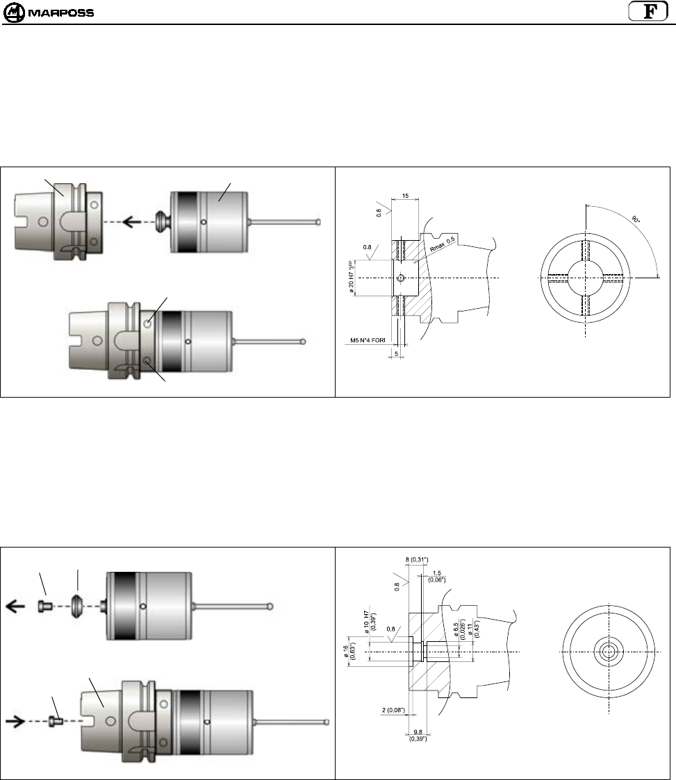
mida 173
12.3 Monter l’émetteur compact E86N-P sur le cône
12.3.1 Fixer l’émetteur E86N-P sur le cône (percer le cône)
• Introduisez le cône (A) dans l’émetteur (B)
• Fixez l’émetteur avec les 4 vis dans les orifices (C)
Figure 12-5. Fixer l’émetteur sur le cône Figure 12-6. Percer le cône
12.3.2 Fixer le cône sur l’émetteur E86N-P sans queue conique (percer le cône)
• dévissez la vis (A) qui fixe la queue conique sur l’émetteur (B)
• Introduisez le cône (C) dans l’émetteur (B)
• Fixez l’émetteur avec la vis (A)
Figure 12-7. Fixer l’émetteur sur le cône Figure 12-8. Percer le cône
A
B
C
C
C
A
B
A
C

FRANÇAIS
E86N- Systeme touch a transmission radio
174
13. MONTER LE STYLET
Nous décrivons ci-dessous la procédure d’installation du stylet sur la sonde montée sur un émetteur standard ; étant donné que
l’émetteur compact a la sonde incorporée et que le porte-stylet est identique, la procédure est la même pour les deux types d’émetteur.
Pour installer le stylet sur la sonde, procédez comme suit :
Nota
bene:
La procédure décrite ci-dessous prévoit l’utilisation de la goupille de rupture. Cette goupille, placée entre le stylet et
la sonde, sert à protéger la sonde en cas de choc accidentel sur le stylet (celui-ci se détache de la sonde).
- Introduisez la goupille de rupture (A) sur la sonde (B).
- Avec la clé (fournie par Marposs), immobilisez le porte-stylet (C) de la sonde et avec l’autre clé, serrez la goupille de rupture (A).
La clé pour serrer la goupille (A) doit se trouver sur la partie inférieure de la goupille, dans la même position (D).
- Vissez le stylet (F) sur la goupille de rupture (A).
- Avec une clé, immobilisez la goupille et avec l’autre, serrez le stylet.
- Introduisez la bague cannelée (E) sur le stylet pour qu’elle enveloppe la goupille de rupture (A). Cette bague sert à retenir le stylet
au moment de la rupture de la goupille.
- Dans les applications via radio, il est conseillé d'utiliser des stylets en porcelaine dure et non pas en acier, pour éviter d'éventuelles
interférences (rares). Si vous n’utilisez pas la goupille de rupture, vissez le stylet directement sur la sonde ; immobilisez le porte-
stylet (C) avec une clé et avec l’autre serrez le stylet.
Figure 13-1
A
B
F
A
A
DC
E
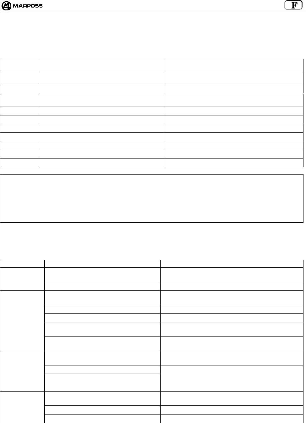
mida 175
14. DIAGNOSTIC
14.1 Messages d’erreur
Sur l’afficheur de l’unité d’interface E86N peuvent apparaître les messages d’erreur suivants :
MESSAGE
D’ALARME
CAUSE REMEDE
E.E2 Erreur de lecture/écriture Contactez l’Assistance technique ou reprogrammez à nouveau
toutes les données.
E.nb Aucune antenne n’est reliée. Vérifiez le raccordement de l’antenne.
L’antenne est mal raccordée. Vérifiez si la seule antenne présente est bien reliée à la borne
inférieure (H1) de l’Interface.
E.b1 Erreur de communication avec l’antenne 1 Vérifiez le raccordement de l’antenne 1.
E.b2 Erreur de communication avec l’antenne 2 Vérifiez le raccordement avec l’antenne 2.
F.P1 Erreur (court-circuit) sur la sortie PROBE 1 Vérifiez le raccordement sur la sortie PROBE 1.
F.P2 Erreur (court-circuit) sur la sortie PROBE 2 Vérifiez le raccordement sur la sortie PROBE 2.
F. Er Erreur (court-circuit) sur la sortie ERROR Vérifiez le raccordement sur la sortie ERROR.
F. Lb Erreur (court-circuit) sur la sortie LOW_BAT Vérifiez le raccordement sur la sortie LOW_BAT.
F. Au Erreur (court-circuit) sur la sortie AUX Vérifiez le raccordement sur la sortie AUX.
Nota bene: Après avoir éliminé les causes de l’erreur, vous pouvez effacer les messages d’erreur sur l’afficheur en pressant
simultanément les touches <Select> et <Enter> 2 secondes au moins (à l’exception des messages E.b1 et E.b2 qui
s’effacent en éteignant puis en rallumant le système).
ATTENTION :
toutes les opérations de mise sous et hors tension du système doivent avoir lieu avec le ou les connecteurs de
l’antenne branché/s.
14.2 Comment interpréter les LEDs
Les LEDs du panneau de l’Unité d’Interface signalent les évènements suivants :
CAUSE REMEDE
L’unité d’interface n’est pas alimentée. Vérifiez si les bornes 16 et 17 de l’unité d’interface sont sous
tension.
LED "POWER"
ETEINTE
Fusible réarmable ouvert Attendez quelques minutes avec l’interface hors tension.
Emetteur- Antenne hors champ de transmission Vérifiez si, pendant les mouvements de la sonde, la LED
verte ""tuning"" présente sur le récepteur reste allumée.
L’émetteur est sans pile ou sa pile est à plat. Remplacez-la.
Le temps pour la transmission est terminé. Donnez un signal de start pour réactiver le système.
L’antenne n’est pas reliée électriquement à
l’interface.
Vérifiez le câble du récepteur et son raccordement à
l’interface.
LED "ERROR"
ALLUMEE"
Une interférence électrique ou électromagnétique
est présente.
Eloignez le câble de l’antenne des câbles d’alimentation.
Changez le canal de travail.
La sonde et l’émetteur ne sont pas reliés
électriquement.
Vérifiez le raccordement entre la sonde et l’émetteur.
La sonde est abîmée.
LED "PROBE":
ELLE NE
CHANGE PAS
D’ETAT AU
CONTACT DE
LA SONDE
L’émetteur est abîmé.
Démontez la sonde de l’émetteur, relier les contacts à ressort
et interrompre le contact. Si malgré tout la LED ne change
pas d’état, l’émetteur est défectueux. S’il change d’état, cela
veut dire que la sonde est défectueuse.
Le stylet est desserré. Vérifiez si le stylet et la goupille de rupture (si utilisée) sont
bien vissés sur la sonde.
La flasque est desserrée. Vissez toutes les vis.
MAUVAISE
REPETABILITE
La garniture interne est percée ou abîmée. Remplacez la sonde.
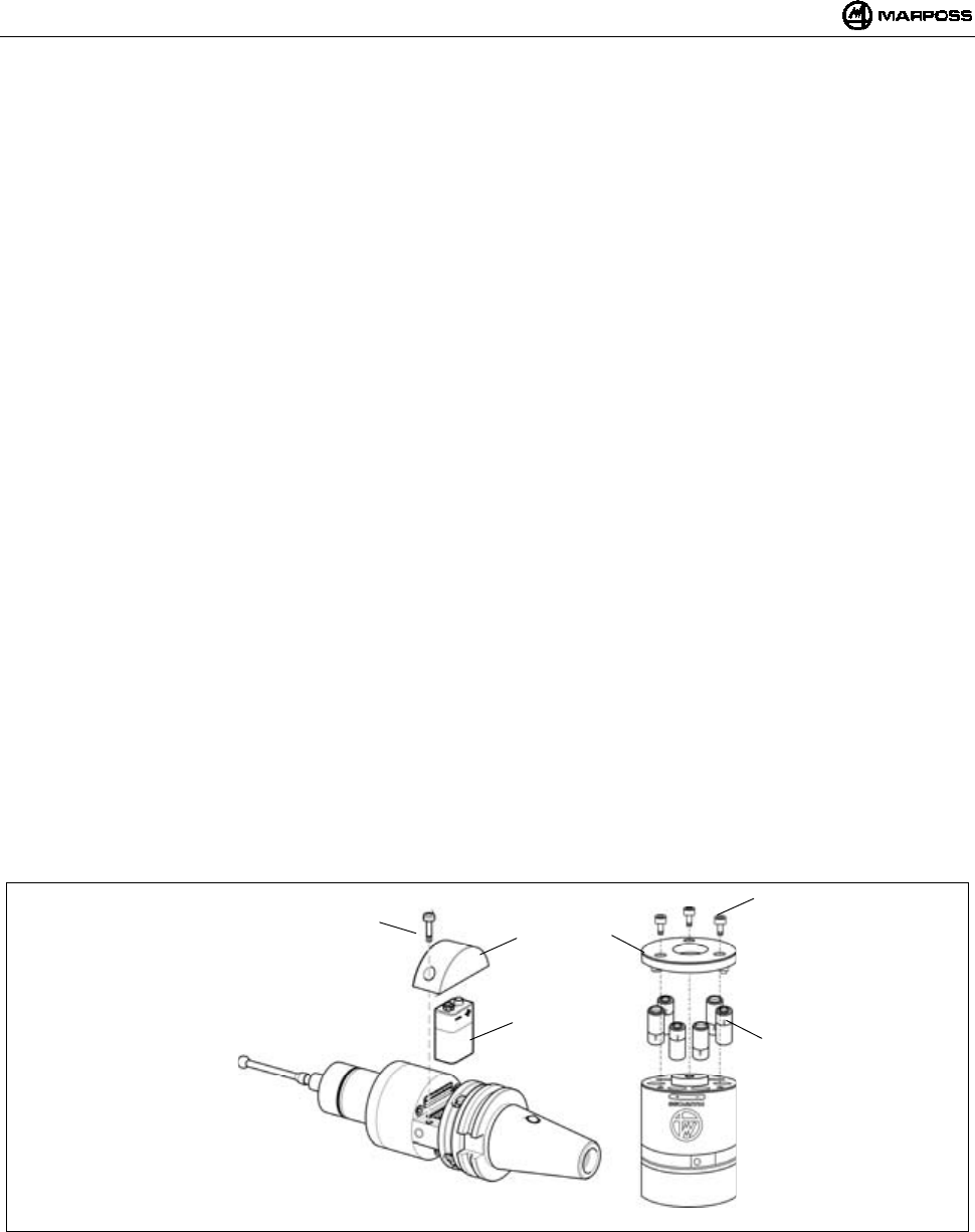
FRANÇAIS
E86N- Systeme touch a transmission radio
176
15. MAINTENANCE
15.1 Maintenance ordinaire
15.1.1 Nettoyage et contrôles
Pour tirer du système de mesure un maximum de profit, il est recommandé de le soumettre régulièrement à un nettoyage et des
contrôles.
Il s’agit d’opérations simples, à effectuer à une périodicité qui varie en fonction des conditions d’utilisation.
- Contrôle de l’état du câblage
Vérifiez périodiquement l’état des câbles et le serrage des bornes.
- Contrôle de l’étanchéité des joints
A l’avant, la sonde est protégée par deux joints qui suffisent à garantir une excellente protection dans des conditions d’emploi
normales. Contrôlez périodiquement que le joint externe ne présente pas de signes d’usure. Si c’est le cas, remplacez-le.
Si le joint interne est abîmé, la sonde devra être envoyée au fournisseur pour la réparation.
15.1.2 Installer/Remplacer la pile de l’émetteur
Pour installer la pile dans l’émetteur ou pour la remplacer quand la LED "low battery" s’allume sur le panneau de l’unité d’interface (le
niveau de la pile sur l’afficheur est égal à 3) et le signal de sortie LOW BATTERY est activé, procédez comme suit :
• EMETTEUR STANDARD :
- Dévissez les deux vis (A) du couvercle (C) où figure le symbole graphique de la pile.
- Retirez la pile à plat, si présente, et installez la nouvelle pile (B) dans les contacts du couvercle (C), en respectant la polarité.
- Remettez le couvercle (C) en place en faisant attention à la position des contacts électriques.
- Revissez les vis (A) en appliquant un couple de serrage de 2Nm.
• EMETTEUR COMPACT :
- Dévissez les trois vis (D) du couvercle (F) et déposez-le.
- Retirez les piles plates, si présentes, et installez les nouvelles piles (E) dans les logements prévus en respectant la polarité sur
le corps de l’émetteur.
- Reposez le couvercle (F) en faisant attention à la position des contacts électriques.
- Revissez les vis (D) en appliquant un couple de serrage de 2Nm.
La rubrique 7.2 “Durée de vie des piles” indique la durée de la batterie suivant l’emploi et le type.
Figure 15-1. Installer/Remplacer les piles
A
B
C
D
F
E

mida 177
15.2 Maintenance extraordinaire
15.2.1 Remplacer la goupille de rupture/stylet
Si le stylet subit un choc accidentel, remplacez la goupille
cassée et/ou le stylet en procédant comme suit.
1 – Otez la bague cannelée (A) en l’extrayant de la goupille
cassée ou pliée.
2 – Libérez le stylet (B) et la sonde (C) de la goupille
cassée (D).
Retirez le stylet abîmé de la sonde (C).
Nota bene: Pour effectuer ces opérations,
immobilisez le porte-stylet de la sonde
avec la clé fournie par Marposs.
3 – Procédez ensuite au montage de la nouvelle goupille et
du stylet (voir "Monter le stylet de la sonde").
Figure 15-2
15.2.2 Remplacer le joint externe
NOTA BENE: cette procédure n'est valide que pour des sondes montées sur des émetteurs standards
1- Retirez le stylet et l’éventuelle goupille de rupture.
2- Extrayez la protection avant (B) du corps de la sonde (A), avec le joint (C).
3- Contrôlez l’état du joint d’étanchéité avant (D) et, le cas échéant, remplacez-le.
4- Installez la nouvelle protection avant avec le joint : vous devez entendre un clic.
Figure 15-3
15.2.3 Remplacer la sonde/l’émetteur
NOTA BENE: cette procédure n'est valide que pour des sondes montées sur des émetteurs standards
1- Retirez le stylet et l’éventuelle goupille de rupture.
Voir "Monter le stylet de la sonde".
2- Procédez au remplacement de la sonde comme l’indique la rubrique "Monter/démonter la sonde et l’émetteur".
D
B
C
A
A
D
B
C
D
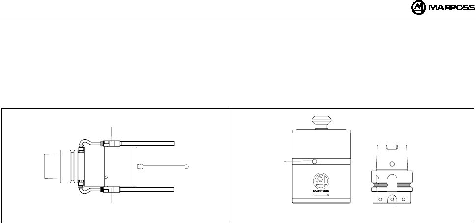
FRANÇAIS
E86N- Systeme touch a transmission radio
178
16. Accessoires
16.1 Groupe support air de nettoyage pour Emetteur compact
Pour fixer le groupe support air de nettoyage (A), utilisez les orifices (B) sur l’émetteur et sur le cône (Figure 16-2). La pression de l’air
doit être de ≤6 bars (88.175psi).
Figure 16-1 Figure 16-2
A
A
B
B

mida 179
17. PIECES DETACHEES
CODE N° DESCRIPTION NOTES
1019108005 Goupille de rupture longueur 15 mm
1019108003 Bague cannelée stylet
2915335018 Kit de pièces détachées pour T25/TL25/TT25 COMPREND :
protection frontale avec joint, joints toriques avant
et arrière, bague stylet
2915340010 Kit de pièces détachées pour T36G COMPREND:
protection frontale sonde avec joint, joints
d’étanchéité et bague stylet
2915345007 Kit de pièces détachées pour T60G/TT60 COMPREND:
protection frontale sonde avec joint, joints
d’étanchéité et bague stylet
2915335013 Protection frontale pour T25/TL25/TT25
2915340006 Protection frontale pour T36
2915345012 Protection frontale pour T60
3415335200 Sonde T25G
3415335201 Sonde T25S
3424306040 Sonde TL25G
3424306041 Sonde TL25S
3415340200 Sonde T36G
3415340201 Sonde T36S
3415345030 Sonde T60G
3415345050 Sonde T60S
3424310000 Sonde TT25
3424310100 Sonde TT25H
3424451000 Sonde TT60
2019923021 Flasque fixation émetteur pour T25/TL25/TT25 Avec joint torique
2019923022 Flasque fixation émetteur pour T36 Avec joint torique
2019923023 Flasque fixation émetteur pour T60/TT60 Avec joint torique
2915335023 Prolongateur pour T25/TL25/TT25 L=23,50 mm
2915335100 Prolongateur pour T25/TL25/TT25 L=50 mm
2915335110 Prolongateur pour T25/TL25/TT25 L=100 mm
2915335120 Prolongateur pour T25/TL25/TT25 L=150 mm
2915340125 Prolongateur pour T36 L=50 mm
2915340126 Prolongateur pour T36 L=100 mm
2915340127 Prolongateur pour T36 L=150 mm
2915345040 Prolongateur pour T60/TT60 L=50 mm
2915345050 Prolongateur pour T60/TT60 L=100 mm
2915345060 Prolongateur pour T60/TT60 L=150 mm
3019917110 Cône DIN 69871/A 40 avec interrupteur et flasque réglable
3019917120 Cône DIN 69871/A 45 avec interrupteur et flasque réglable
3019917130 Cône DIN 69871/A 50 avec interrupteur et flasque réglable
3019917140 Cône CAT 40 avec interrupteur et flasque réglable
3019917150 Cône CAT 45 avec interrupteur et flasque réglable
3019917160 Cône CAT 50 avec interrupteur et flasque réglable
1502027040 Joint pour demi-coque
1502027050 Joint demi-coque (côté contacts)
1502018260 Vis spécial pour porte-pile
4162100005 Pile Alcaline 9V
4162100302 Pile Lithium 9V
6180830500 Couvercle porte-pile sans contacts
2015340100 Jeu de clés COMPREND :
clés pour le stylet et clés Allen de
1,5 – 2 – 2,5 – 3 – 4 mm
1320131000 Clé spéciale pour T25/TL25/TT25
1320367000 Clé spéciale pour flasque T25/TL25/T36/T60/TT25/TT60
2919917110 Flasque réglable pour émetteur Standard
6871982001 Emetteur E86N à activation radio
EMETTEUR STANDARD E86N ET SONDES
6871982101 Emetteur E86N à activation mécanique

FRANÇAIS
E86N- Systeme touch a transmission radio
180
CODE N° DESCRIPTION NOTES
1019108005 Goupille de rupture longueur 15 mm
1019108003 Bague cannelée stylet
2015340100 Jeu de clés COMPREND:
clés pour le stylet et clés Allen de :
1,5 – 2 – 2,5 – 3 – 4 mm
4400000219 Joints toriques 2081 PARKER 2-19 (pour couvercle pile)
4306400804 Vis UNI-5931-12K M4X8 (pour couvercle pile)
4162100004 Pile Alcaline 1,5V
6180980085 Groupe air de nettoyage
EMETTEUR COMPACT E86N-P
6871983000 Emetteur E86N-P à activation radio
6871980000 Antenne E86N
6180985017 Câble de raccord antenne 15m
ANTENNE ET PROLONGATEUR
AVEC CONNECTEUR
6180985027 Câble de raccord antenne 30m
INTERFACE
8304870000 Interface E86N
ACCESSOIRES
6739696319 Cordon d’Extension – E86N CNC HEIDEN HAIN

mida 181
E86N
SISTEMA TOUCH CON TRANSMISIÓN RADIO
Manual de instalación y uso

ESPAÑOL
E86N- Sistema touch con transmisión radio
182
Se prohíbe la dispersión en el ambiente y la eliminación como residuo urbano o
genérico del producto y de cualquier parte que pueda separarse mecánicamente del
mismo (Ley de transposición nacional de las directivas europeas 2002/95/CE y
2002/96/CE y demás). Las disposiciones de ley se aplican sólo a los productos
identificados RAEE con el correspondiente logo, siempre y cuando hayan aparecido
en el mercado a partir del 13 de agosto de 2005.
El producto RAEE una vez desechado puede contener substancias y partes dañinas para el hombre y
para el ambiente que tienen que recibir un tratamiento profesional para la reutilización, reciclado y
eliminación definitiva.
Entregue el producto RAEE a un centro autorizado para el tratamiento RAEE, o bien contacte con la
autoridad local competente o con el centro de asistencia Marposs más próximo para mayor información.
La eliminación clandestina de un producto RAEE es un delito castigado con sanciones.
2002/95/CE
2002/96/CE
MARPOSS S.p.A. no se asume la obligación de notificar supuestas modificaciones del producto efectuadas a posteriori.
Las indicaciones del presente manual no autorizan bajo ningún concepto manipulaciones por parte de personal no autorizado.
La garantía de los equipos decae en el momento en que se detecten dichas manipulaciones.

mida 183
Índice
1. NORMAS Y ADVERTENCIAS GENERALES...................................................................................................................................... 185
2. COMPONENTES DEL SISTEMA......................................................................................................................................................... 186
3. CONFIGURACIÓN Y FUNCIONAMIENTO.......................................................................................................................................... 187
4. MODO DE EMPLEO ............................................................................................................................................................................ 188
5. SONDA DE MEDIDA Y TRANSMISOR COMPACTO E86N-P ........................................................................................................... 189
6. TRANSMISIÓN RADIO ........................................................................................................................................................................ 190
6.1 Descripción .................................................................................................................................................................................. 190
6.1.1 Distancias de utilización para varios sistemas ...................................................................................................................... 190
6.2 Activación de la transmisión ........................................................................................................................................................ 191
6.2.1 Activación radio ..................................................................................................................................................................... 191
6.2.2 Activación mecánica.............................................................................................................................................................. 191
6.3 Desactivación de la transmisión .................................................................................................................................................. 191
6.3.1 Transmisor con activación radio............................................................................................................................................ 191
6.3.2 Transmisor con activación mecánica .................................................................................................................................... 191
7. TRANSMISOR E86N............................................................................................................................................................................ 192
7.1 Descripción .................................................................................................................................................................................. 192
7.2 Duración de la batería e indicaciones en la Interfaz.................................................................................................................... 193
7.3 Dimensiones transmisor con sondas ........................................................................................................................................... 194
7.3.1 Transmisor estándar con brida estándar............................................................................................................................... 194
7.3.2 Transmisor estándar con brida de regulación ....................................................................................................................... 195
7.4 Dimensiones transmisor compacto.............................................................................................................................................. 196
Transmisor compacto E86N-P ........................................................................................................................................................... 196
7.4.2 Transmisor compacto E86N-P sin vástago cónico................................................................................................................ 196
8. RECEPTOR E86N................................................................................................................................................................................ 197
8.1 Descripción Antena y prolongación con conector........................................................................................................................ 197
8.2 Modo pantalla a distancia ............................................................................................................................................................ 197
8.3 Conexión de la antena ................................................................................................................................................................. 197
8.4 Instalación de la antena ............................................................................................................................................................... 198
9. UNIDAD DE INTERFAZ E86N............................................................................................................................................................. 199
Panel delantero unidad de interfaz ....................................................................................................................................................... 199
9.2 Dimensiones unidad de la interfaz............................................................................................................................................... 200
9.3 Características técnicas Interfaz E86N........................................................................................................................................ 200
9.4 Conexiones a la unidad de interfaz.............................................................................................................................................. 201
9.4.1 Selección del código de identificación................................................................................................................................... 201
9.5 Diagrama I/O unidad de interfaz E86N ........................................................................................................................................ 202
10. PROGRAMACIÓN DEL SISTEMA .................................................................................................................................................... 203
10.1 Programación de la interfaz ......................................................................................................................................................... 204
10.2 Programación del Transmisor...................................................................................................................................................... 207
10.3 Programación del transmisor en el modo Recovery.................................................................................................................... 209
10.4 Análisis ocupación del espectro electromagnético (función “Sniffer”) ......................................................................................... 210
10.4.1 Exploración............................................................................................................................................................................ 211
10.4.2 Visualización de los resultados ............................................................................................................................................. 211
11. INSTALACIÓN SONDA – TRANSMISOR ESTÁNDAR .................................................................................................................... 212
11.1 Instalación sonda – transmisor estándar ..................................................................................................................................... 212
11.2 Inserción prolongaciones para sondas (opcionales).................................................................................................................... 213
12. INSTALACIÓN DEL TRANSMISOR.................................................................................................................................................. 214
12.1 Instalación del transmisor Estándar en el cono ........................................................................................................................... 214
12.2 Instalación transmisor Estándar en el cono con brida de regulación........................................................................................... 215
12.3 Instalación transmisor compacto E86N-P en el cono .................................................................................................................. 217
12.3.1 Fijación transmisor E86N-P al cono (mecanizado del cono)................................................................................................. 217
12.3.2 Fijación al cono del transmisor E86N-P sin mango cónico (mecanizado del cono).............................................................. 217
13. INSTALACIÓN DEL BRAZO ............................................................................................................................................................. 218
14. DIAGNÓSTICO .................................................................................................................................................................................. 219
14.1 Mensajes de error ........................................................................................................................................................................ 219
14.2 Señalización de los Led............................................................................................................................................................... 219
15. MANTENIMIENTO ............................................................................................................................................................................. 220
15.1 Mantenimiento ordinario .............................................................................................................................................................. 220
15.1.1 Limpieza y controles.............................................................................................................................................................. 220
15.1.2 Inserción/Reemplazo Batería Transmisor ............................................................................................................................. 220

ESPAÑOL
E86N- Sistema touch con transmisión radio
184
15.2 Mantenimiento extraordinario....................................................................................................................................................... 221
15.2.1 Reemplazo clavija de rotura/brazo ........................................................................................................................................ 221
15.2.2 Reemplazo junta externa.......................................................................................................................................................221
15.2.3 Reemplazo sonda/transmisor ................................................................................................................................................ 221
16. ACCESORIOS.................................................................................................................................................................................... 222
16.1 Grupo soporte aire de limpieza para Transmisor Compacto ....................................................................................................... 222
17. LISTA PIEZAS DE REPUESTO.........................................................................................................................................................223
mida 185
1. NORMAS Y ADVERTENCIAS GENERALES
PREMISA
Este manual de instrucciones proporciona toda información específica necesaria para el conocimiento y la correcta utilización del
equipo MARPOSS que Ud. posee.
Las indicaciones de este manual se dirigen al siguiente tipo de personal:
• Personal MARPOSS o del Cliente que debe efectuar la instalación del equipo.
• Personal técnico del Cliente que debe proceder directamente con el equipo MARPOSS.
• Personal técnico del Cliente responsable del mantenimiento de la línea productiva en la que se instala el equipo MARPOSS.
TODOS LOS DERECHOS QUEDAN RESERVADOS. ESTE MANUAL ESTÁ DESTINADO SOLO PARA USO INTERNO DEL CLIENTE. SE PROHÍBE CUALQUIER
OTRO USO.
ENSAYO Y GARANTÍA
Los materiales defectuosos están cubiertos por garantía con las siguientes limitaciones:
• DURACIÓN DE LA GARANTÍA: la garantía cubre el producto y todas las reparaciones efectuadas dentro de los términos concordados.
• OBJETO DE LA GARANTÍA: la garantía se aplica al producto y a sus partes marcadas con el número de placa u otro número de
identificación usado por MARPOSS.
La garantía arriba mencionada es válida a no ser que MARPOSS y el Cliente estipulen distintos acuerdos.
NORMAS DE SEGURIDAD GENERALES
El equipo ha sido fabricado de conformidad a las normas CEI EN60950.
CONVENCIONES Y SÍMBOLOS UTILIZADOS
En la redacción del manual se han adoptado algunas modalidades tipográficas.
En particular, se han definido dos tipos de aviso de seguridad:
Advertencia:
Esta señalización indica la posibilidad de daños para la unidad electrónica y para otros dispositivos conectados a la misma,
o bien la posibilidad de perder datos.
Atención:
Esta señalización indica condiciones de riesgo para el operador o para el técnico.
Las informaciones de especial importancia que pueden facilitar la comprensión y la utilización del sistema están en el interior de un
recuadro, marcado por "Nota", y en negrita.

ESPAÑOL
E86N- Sistema touch con transmisión radio
186
2. COMPONENTES DEL SISTEMA
A1 - Sonda y transmisor E86N (estándar)
A2 - Transmisor E86N-P (compacto)
B - Clavija de rotura (opcional)
C - Retén brazo (opcional)
D - Brazo
E - Antena
F - Unidad de interfaz E86N
G - Dos llaves abiertas CH 5 - 5.5 y kit llaves hexagonales
H - Una llave especial para sonda T25 y prolongaciones mecánicas
I - Prolongaciones para sondas (opcional)
L - Antena auxiliar (opcional)
Figura 2-1. Componentes del sistema.
A1
B
C
D
E
G
F
H
I
L
A2
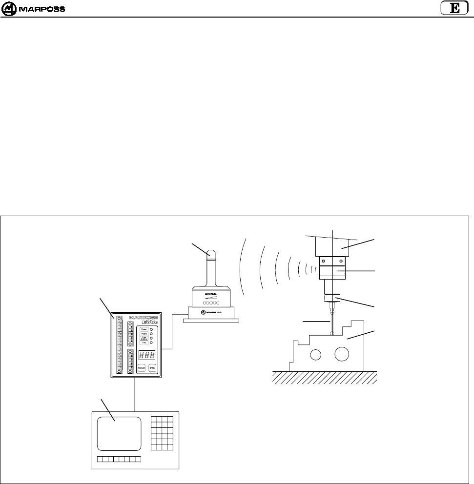
mida 187
3. CONFIGURACIÓN Y FUNCIONAMIENTO
El sistema touch con transmisión radio sirve para identificar unos puntos en el espacio que, procesados por el CNC de la máquina
herramienta, determinan unas mediciones. Dichos puntos son detectados por la sonda, microinterruptor multidireccional de precisión, y
enviados por medio del sistema de transmisión radio, compuesto por un transmisor y un receptor, a la unidad de interfaz y por ésta son
adaptados al CNC. El ciclo de medida llama desde el almacén herramientas el grupo sonda/transmisor instalado en el portaherramienta
y lo inserta en el husillo. El sistema es fácil de utilizar y está diseñado para trabajar en los entornos industriales más difíciles. Se utiliza
en centros de mecanizado y fresadoras para: la identificación, el posicionamiento, la medición de la pieza a mecanizar y la
medición de la pieza mecanizada.
La aplicación típica del sistema consta de:
A - Pieza a medir E - Husillo máquina herramienta
B - Brazo F - Antena E86N
C - Sonda touch G - Unidad de interfaz E86N
D - Transmisor E86N H - CNC de la máquina herramienta
Figura 3-1. Configuración y funcionamiento.
BA
C
D
E
F
G
H
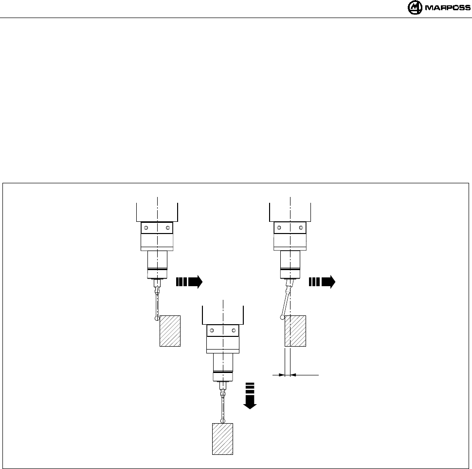
ESPAÑOL
E86N- Sistema touch con transmisión radio
188
4. MODO DE EMPLEO
El equipo de medición es multidireccional en el hemisferio x/y/+z.
El contacto del brazo con la superficie de la pieza a inspeccionar genera una señal utilizada por la máquina herramienta para
memorizar el punto de contacto y para detener los ejes de la máquina. Para conseguir una buena repetibilidad del equipo es
aconsejable utilizar una velocidad de medida constante.
La velocidad de medida seleccionada debe permitir un paro del eje máquina dentro de los límites de extracarrera de la sonda
utilizada.
Antes de utilizar la sonda hay que compensar el error sistemático de medida del equipo compuesto por sonda, máquina
herramienta y CNC efectuando una calibración. El error sistemático es característico de cada dirección de medida y repetible, por
lo tanto la calibración debe efectuarse en cada dirección donde se detectará la medida. Para calibrar el equipo es aconsejable
medir los puntos en la máquina de valor conocido (R) y calcular las diferencias entre éstos y los valores medidos (R+K1). Dicha
diferencia (K1) se introduce en los parámetros correctores herramientas del CNC y se llama cada vez que se ejecuta una medida
en la misma dirección.
Figura 4-1. Modo de empleo.
X/Y X/Y
Z
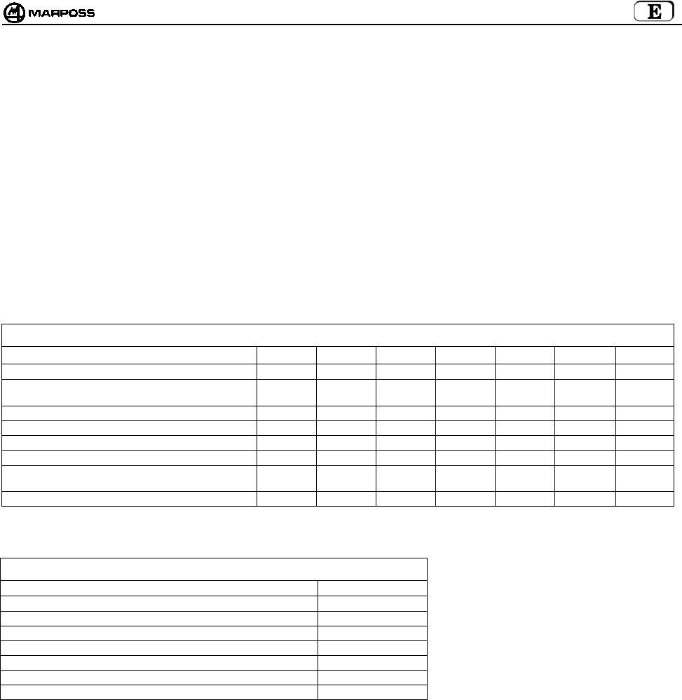
mida 189
5. SONDA DE MEDIDA Y TRANSMISOR COMPACTO E86N-P
La sonda de medida es un microinterruptor multidireccional de precisión utilizada en las aplicaciones en máquinas de remoción de
virutas de CN, para el control y la medida de herramientas y piezas.
Están disponibles varios modelos de sondas touch multidireccionales en el hemisferio x/y/+z.
Para algunos modelos de sonda hay dos diferentes versiones según el tipo de protección delantera:
• “Versión G” con junta entelada para una mejor protección contra el líquido refrigerante.
• “Versión S” con pantalla metálica de protección contra virutas.
Para resolver de manera optimal las específicas exigencias que se manifiestan en las distintas máquinas herramientas, están
disponibles las siguientes sondas:
Sonda T25G / T25S
Sonda TL25G / TL25S
Sonda T36G / T36S
Sonda T60G / T60S
Sonda TT25 (solo con junta)
Sonda TT25H (solo con junta)
Sonda TT60 (solo con junta)
Tabla 5-1. Características técnicas de la sonda.
Tipo sonda T25 TL25 T36 T60 TT25 TT25H TT60
Ejes sonda ±X, ±, Y+Z±X, ±Y, +Z±X, ±Y, +Z±X, ±Y,+Z±X, ±Y,+Z±X, ±Y,+Z±X, ±Y,+Z
Repetibilidad unidireccional sonda (2 σ) con velocidad
hasta 600 mm/min.
0,5 µm0,5 µm0,5 µm1 µm1 µm2 µm1 µm
Fuerza de medida en el plano X, Y 200 gf 90 gf 260 gf 280 gf 50-95 gf 90-175 gf 70-120 gf
Fuerza de medida en la dirección Z 1200 gf 550 gf 1200 gf 1200 gf 580 gf 1080 gf 580 gf
Extracarrera en el plano X, Y 11,2 mm 11,2 mm 14,4 mm 22 mm 11,6 mm 11,6 mm 19 mm
Extracarrera en la dirección Z4 mm 4 mm 4,2 mm 6,4 mm 4 mm 4 mm 6,4 mm
CARACTERÍSTICAS DEL BRAZO DE 35 mm 35 mm 40 mm 50 mm 35 mm 35 mm 50 mm
Grado de protección según normas IEC IP67 IP67 IP67 IP67 IP67 IP67 IP67
A diferencia del transmisor Estándar, en el que puede instalarse cualquier sonda de medida que aparece en la Tabla 5-1, el transmisor
Compacto E86N-P incorpora la sonda y sus características técnicas son las siguientes:
Tabla 5-2. Características técnicas del transmisor compacto.
Ejes ±X, ±, Y+Z
Repetibilidad unidireccional (2 σ) con velocidad hasta 600 mm/min. 0,5 µm
Fuerza de medida en el plano X, Y 200 gf
Fuerza de medida en la dirección Z 1200 gf
Extracarrera en el plano X, Y 11,2 mm
Extracarrera en la dirección Z4 mm
CARACTERÍSTICAS DEL BRAZO DE 35 mm
Grado de protección según normas IEC IP68
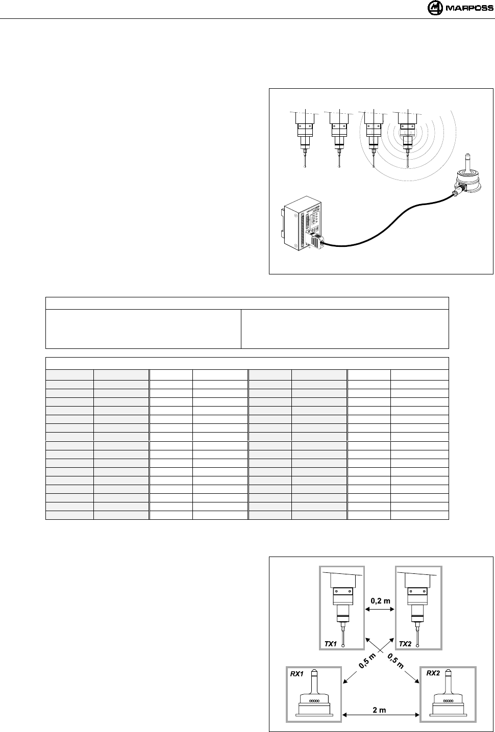
ESPAÑOL
E86N- Sistema touch con transmisión radio
190
6. TRANSMISIÓN RADIO
6.1 Descripción
El sistema de transmisión radio está compuesto por tres elementos:
Transmisor: envía las informaciones necesarias para el CNC
para procesar la medida.
Antena: recibe la señal del transmisor y la envía a la unidad de
interfaz E86N.
Unidad de interfaz: procesa las señales y las convierte en una
forma utilizable por el CNC.
El equipo E86N permite la programación de 64 canales de
transmisión diferentes por medio de teclado en la interfaz (véase el
capítulo 10 "PROGRAMACIÓN DEL SISTEMA” pág. 203)
Para aumentar el campo de transmisión y la fiabilidad de la
comunicación radio, es posible conectar dos antenas a la unidad de
interfaz E86N.
El equipo permite utilizar hasta un máximo de 4 transmisores en la
misma máquina herramienta (Figura 6-1) que funcionan en el mismo
canal y que pueden activarse alternativamente, uno a la vez, por medio
de un diferente código de identificación (véase el párrafo 10.2
“Programación del Transmisor" pág. 207).
Figura 6-1. Sistema de transmisión radio.
Tabla 6-1. Características técnicas.
-Distancia de transmisión : 15 m -Potencia de activación : <10 mW
-Potencia de transmisión : <1mW -Número canales de transmisión : 64
-Distancia de activación, desactivación y
programación
: 5 m -Frecuencia de transmisión :433,075÷434,775 Mhz
Tabla 6-2. Frecuencias de transmisión.
CANAL FRECUENCIA CANAL FRECUENCIA CANAL FRECUENCIA CANAL FRECUENCIA
1 433,075 17 433,475 33 434,000 49 434,400
2 433,100 18 433,500 34 434,025 50 434,425
3 433,125 19 433,525 35 434,050 51 434,450
4 433,150 20 433,550 36 434,075 52 434,475
5 433,175 21 433,575 37 434,100 53 434,500
6 433,200 22 433,600 38 434,125 54 434,525
7 433,225 23 433,625 39 434,150 55 434,550
8 433,250 24 433,650 40 434,175 56 434,575
9 433,275 25 433,675 41 434,200 57 434,600
10 433,300 26 433,700 42 434,225 58 434,625
11 433,325 26 433,725 43 434,250 59 434,650
12 433,350 28 433,750 44 434,275 60 434,675
13 433,375 29 433,775 45 434,300 61 434,700
14 433,400 30 433,800 46 434,325 62 434,725
15 433,425 31 433,825 47 434,350 63 434,750
16 433,450 32 433,850 48 434,375 64 434,775
6.1.1 Distancias de utilización para varios sistemas
Para evitar interferencias entre sistemas situados en proximidad
deben respetarse las siguientes distancias:
• Como mínimo 2 metros entre las Antenas de los sistemas,
independientemente de la utilización de canales adyacentes (ej.
CH5 y CH6).
• Como mínimo 0,2 metros entre los Transmisores de los
sistemas, independientemente de la utilización de canales
adyacentes.
• Como mínimo 0,5 metros entre el transmisor de un sistema y la
Antena del otro funcionando en canales adyacentes.
NOTA: en el caso de utilización de 2 sistemas en la misma
máquina (por ej. Centros de mecanizado de doble
husillo), además de respetar las distancias indicadas
Figura 6-2, hay que utilizar dos canales NO adyacentes
y códigos de identificación “A” y “D”.
• La distancia entre sistemas que operan en el mismo canal debe
ser superior a 100 metros.
Figura 6-2. Distancias de utilización para más sistemas.
ABCD
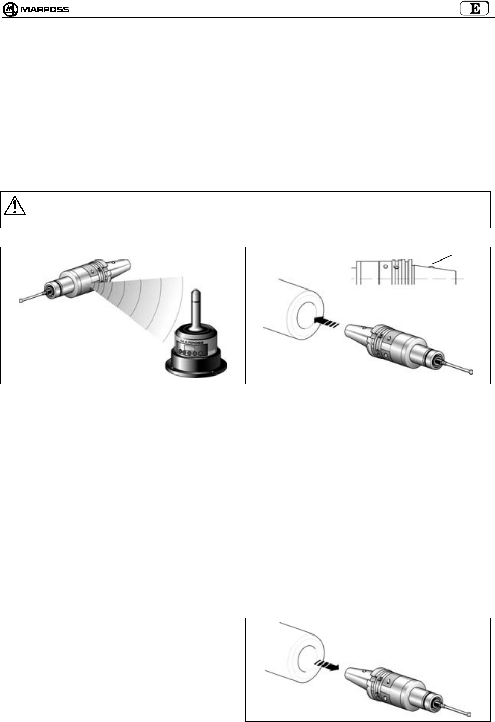
mida 191
6.2 Activación de la transmisión
El transmisor está normalmente en condiciones de espera (stand-by); la activación de la transmisión puede realizarse de dos maneras
según la versión del transmisor:
•activación radio
•activación mecánica (solo para Transmisor Estándar)
6.2.1 Activación radio
La activación del sistema se realiza tras el envío de una señal radio de la antena al transmisor. El mando de activación del sistema
(START) está generado por la unidad de interfaz de 2 maneras:
Por medio de conexión de la señal de entrada START/STOP a la lógica de la máquina (código M).
Desde el teclado presionando (durante 2 segundos como mínimo) la tecla <select>
6.2.2 Activación mecánica
En el cono portaherramienta hay un microinterruptor (H). La inserción del cono en el husillo causa la activación de la transmisión.
Advertencia:
Cuando se vuelve a colocar el transmisor en el almacén herramientas, asegúrese que no se accione el microinterruptor de
activación.
Figura 6-3. Activación radio. Figura 6-4. Activación mecánica.
6.3 Desactivación de la transmisión
La desactivación de la transmisión puede realizarse de dos distintas maneras, conforme a la versión del Transmisor.
6.3.1 Transmisor con activación radio
DESACTIVACIÓN RADIO:
1. Lógica de la máquina
La desactivación se realiza por medio de mando de la máquina en la entrada START/STOP (código M).
2. Desde Teclado
presionando (durante 2 segundos como mínimo) la tecla <select>
DESACTIVACIÓN AUTOMÁTICA
La desactivación se ejecuta al caducar el tiempo programado en el temporizador del transmisor (véase el párrafo 10.2
“Programación del Transmisor" pág. 207).
6.3.2 Transmisor con activación mecánica
• DESACTIVACIÓN MECÁNICA
La desactivación se efectúa cuando el transmisor se saca
del husillo.
• DESACTIVACIÓN AUTOMÁTICA
La desactivación se ejecuta al caducar el tiempo
programado en el temporizador del transmisor (véase el
párrafo 10.2 “Programación del Transmisor" pág. 207).
Figura 6-5. Ejemplo de desactivación mecánica.
H
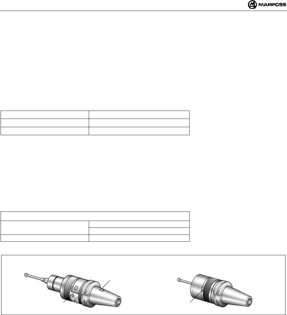
ESPAÑOL
E86N- Sistema touch con transmisión radio
192
7. TRANSMISOR E86N
7.1 Descripción
Actualmente hay dos tipos de transmisor:
• TRANSMISOR ESTÁNDAR
En el que se fijan, por medio de adecuadas bridas, los varios tipos de sonda
• TRANSMISOR COMPACTO
La sonda está en el interior del Transmisor
El transmisor envía a la antena las siguientes informaciones necesarias para el CNC para procesar la medida:
• Estado de la sonda: sonda con brazo en reposo/sonda con brazo desviado
• Estado de la batería: cargada o casi descargada
Un LED verde (L) indica el estado de la sonda, de la batería y de la transmisión:
LED encendido permanente : Sonda con brazo desviado
1 impulso cada 2s : Transmisión activada
2 impulsos cada 2s : Batería casi descargada
Los Transmisores Estándares, se subdividen a su vez en:
• TRANSMISORES CON ACTIVACIÓN RADIO:
La transmisión es activada por una señal enviada desde la antena.
• TRANSMISORES CON ACTIVACIÓN MECÁNICA:
La transmisión se activa por medio del microinterruptor (H) situado en el cono portaherramientas.
El microinterruptor no está presente en el transmisor con activación radio.
ATENCIÓN: La activación mecánica está prevista solo en los transmisores Estándares y no en los compactos.
Para la programación del Transmisor véase el párrafo 10.2 “Programación del Transmisor" pág. 207.
Tabla 7-1. Características técnicas.
Alimentación: : batería 9V (transmisor estándar)
: 6 baterías 1,5 V (transmisor compacto)
Distancia de transmisión : 15m
Figura 7-1. Transmisores.
H
Transmisor Estándar Transmisor Compacto
LL
mida 193
7.2 Duración de la batería e indicaciones en la Interfaz
El estado de carga de las baterías del Transmisor es señalizada en la Interfaz, tanto por los relativos Led (Led Low Battery o Led Error)
como en pantalla (con sistema activado presionando la tecla <select> se visualiza a la izquierda el código de Identificación y a la
derecha el nivel de carga “7” valor Máx y “0” batería completamente descargada). En especial se verifica lo siguiente:
• El Led “Low battery” se enciende en correspondencia del Nivel “3” en pantalla
• El Led “Error” se enciende en correspondencia del Nivel “0” en pantalla
El valor de carga visualizado en pantalla permanece memorizado hasta la siguiente activación.
La duración de la batería depende del tiempo de utilización del transmisor y del tipo de batería utilizada. En la tabla se hallan los
valores de duración según la batería y en condiciones de funcionamiento seguido y stand-by del transmisor:
• Transmisor estándar
TIPO BATERÍA BATERÍA ACONSEJADA FUNCIONAMIENTO SEGUIDO FUNCIONAMIENTO STAND-BY
Alcalina DURACELL MN1604
DURACELL PC1604 PROCELL
ENERGIZER X22
ENERGIZER 522
150 horas 170 días
Litio ENERGIZER L522
ULTRALIFE U9VL
DURACELL PL1604
SONNENSCHEIN SLM9-J
320 horas 380 días
Nota: Una batería alcalina se suministra con el transmisor en el embalaje. Insertar la batería en el transmisor
antes de la instalación (véase el párrafo 15.1.2 “Inserción/Reemplazo Batería Transmisor” pág. 220).
Advertencia:
TRANSMISOR CON ACTIVACIÓN MECÁNICA
Comprobar que en el alojamiento del cono en el almacén herramientas haya una conformación que pueda
evitar el accionamiento del microinterruptor (H) de activación.
BATERÍAS AL LITIO: las baterías al litio pueden explotar si no se reemplazar correctamente. Reemplazar solo
con tipo igual o equivalente (véase la tabla). Eliminar las baterías usadas de conformidad a las normas
vigentes.
• Transmisor compacto
TIPO BATERÍA BATERÍA ACONSEJADA FUNCIONAMIENTO SEGUIDO FUNCIONAMIENTO STAND-BY
DURACELL MN9100
Alcalina
ENERGIZER E90
230 horas 250 días
Nota: las baterías se suministran con el transmisor en el embalaje.
Insertar las baterías en el transmisor antes de la instalación (véase el párrafo 15.1.2 “Inserción/Reemplazo
Batería Transmisor” pág. 220).
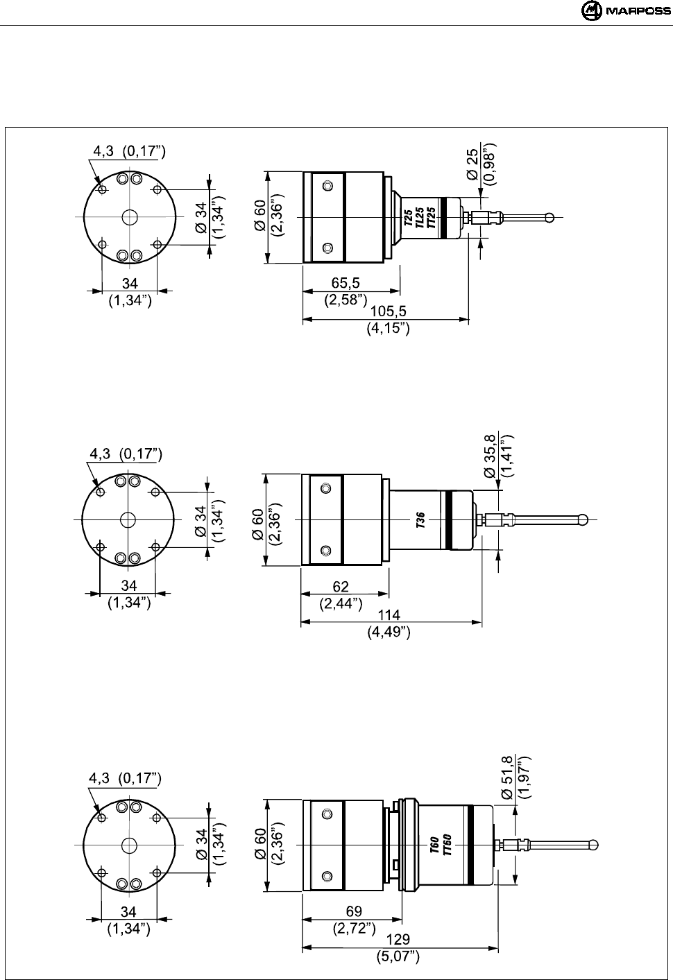
ESPAÑOL
E86N- Sistema touch con transmisión radio
194
7.3 Dimensiones transmisor con sondas
7.3.1 Transmisor estándar con brida estándar
Figura 7-2. Dimensiones transmisor con brida estándar.
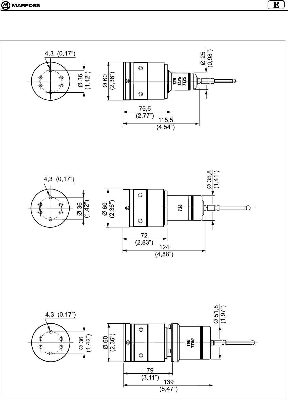
mida 195
7.3.2 Transmisor estándar con brida de regulación
Figura 7-3. Dimensiones transmisor con brida de regulación.

ESPAÑOL
E86N- Sistema touch con transmisión radio
196
7.4 Dimensiones transmisor compacto
7.4.1 Transmisor compacto E86N-P
Figura 7-4
7.4.2 Transmisor compacto E86N-P sin vástago cónico
Figura 7-5
N°3 VITI M4X6
N°3 VITI M4X6
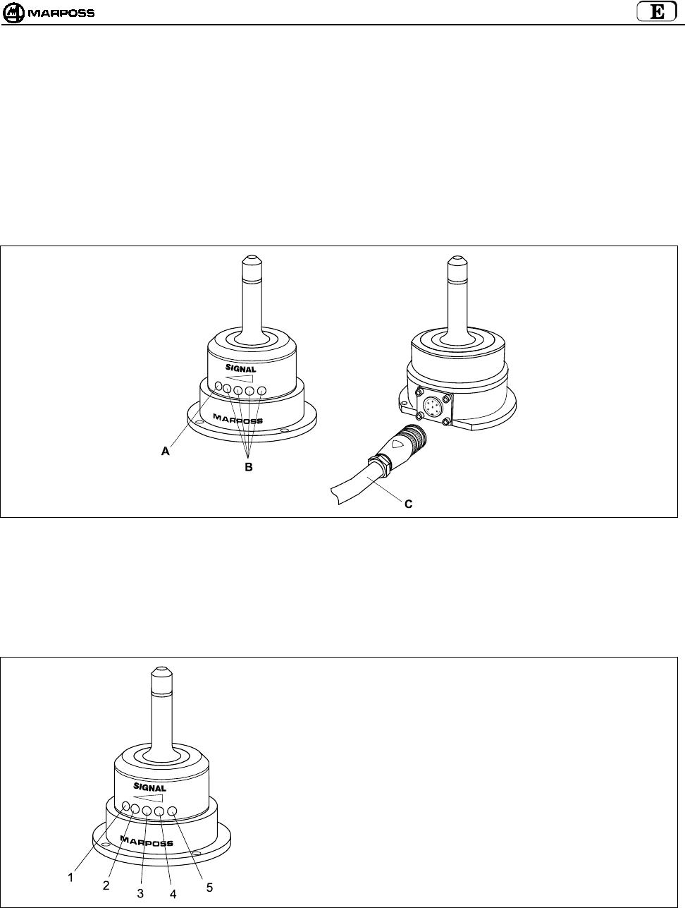
mida 197
8. RECEPTOR E86N
8.1 Descripción Antena y prolongación con conector
La antena recibe los datos emitidos por el transmisor y los envía a la unidad de interfaz E86N a la que está conectada por medio del
cable con conector.
En la parte delantera de la antena hay:
A- Un LED rojo. Encendido indica que la transmisión no se está efectuando o bien que la señal del transmisor no se ha recibido.
B- Un LED amarillo y tres LED verdes. Indican la intensidad de la señal recibida. El encendido de los LED facilita, durante la
instalación, el correcto posicionamiento de la antena.
C- Cable de conductores encerrados con conector (de longitud 15m o 30m) para la conexión a la unidad de interfaz E86N.
Figura 8-1: Antena y cable con conector.
8.2 Modo pantalla a distancia
Los led presentes en la Antena además pueden funcionar como pantalla a distancia de la unidad de interfaz, en caso de que en fase de
programación de la interfaz se programe correctamente el dato “rd” (remote display) (véase el párrafo 10.1 “Programación de la
interfaz” pág. 204).
En este caso los Led asumen el siguiente significado:
1 -
2 -
3 -
4 -
5 -
Led ROJO= ERROR
Led AMARILLO= LOW BAT
Led VERDE= siempre apagado
Led VERDE= PROBE
Led VERDE= POWER
Figura 8-2. Funcionamiento de la Antena como panel a distancia de la Unidad de Interfaz.
8.3 Conexión de la antena
La antena debe conectarse al tablero de bornes de la unidad de interfaz E86N (véase el esquema de conexión en el párrafo 9.4
"Conexiones a la unidad de interfaz” pág. 201
La antena se suministra sin el cable con conector.
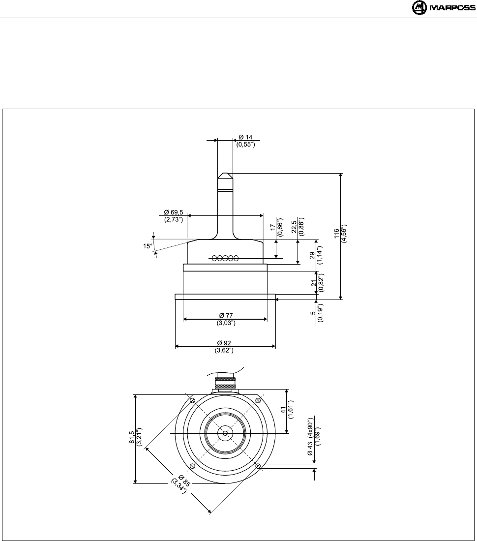
ESPAÑOL
E86N- Sistema touch con transmisión radio
198
8.4 Instalación de la antena
• La antena puede fijarse provisionalmente por medio de la base magnética para definir la posición de fijación más adecuada y
comprobar que la señal emitida por el transmisor sea recibida durante los desplazamientos del sistema de palpación.
• Para la instalación permanente fijar la antena con los cuatro tornillos suministrados con el equipo.
Figura 8-3
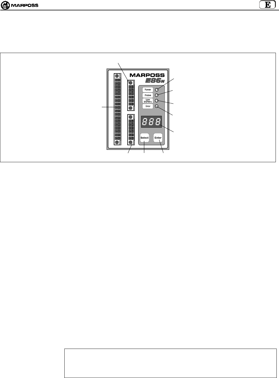
mida 199
9. UNIDAD DE INTERFAZ E86N
9.1 Panel delantero unidad de interfaz
Figura 9-1: Panel delantero.
A- LED “power” (verde) : encendido con tensión de alimentación presente.
B- LED “probe” (verde) : indica el estado de la sonda. Encendido cuando el brazo de la sonda está desviado. Apagado
cuando el brazo de la sonda está en reposo.
C- LED “low battery”
(amarillo)
: encendido indica que la batería está casi descargada. (Véase el párrafo 7.2 “Duración de la batería
e indicaciones en la Interfaz” pág. 17 y señal de salida LOW BAT párrafo 9.4 "Conexiones a la
unidad de interfaz” pág. 201).
D- LED “error” (rojo) : indica una condición de error. Se enciende cuando la transmisión no está activada, cuando la sonda
está fuera del campo de transmisión (véase asimismo la señal de salida ERROR 9.4 "Conexiones a
la unidad de interfaz” pág. 201) y cuando la batería está completamente descargada (véase el
párrafo 7.2 “Duración de la batería e indicaciones en la Interfaz” pág. 193).
E- PANTALLA : pantalla de led con tres cifras de siete segmentos. En condiciones normales de funcionamiento
puede visualizar el canal radio de funcionamiento, el código de identificación y el estado de carga
de la batería.
En programación visualiza todos los valores programables.
F-TECLA ENTER : Si se presiona más de 2 segundos seguidos permite a la interfaz entrar en el modo de
programación.
En programación, confirma el dato seleccionado y hace pasar al siguiente.
Si se presiona más de 2 segundos simultáneamente a la tecla <Select>, permite la eliminación de
mensajes de alarma presentes en la pantalla de la interfaz.
G-TECLA SELECT :Si se presiona durante 2 segundos como mínimo permite la visualización a la izquierda del código
de Identificación y a la derecha del nivel de carga de la batería
Si se presiona durante más de 2 segundos permite la Activación/Desactivación manual del sistema
Si se presiona durante 2 segundos simultáneamente a la tecla <Enter> permite la eliminación de los
mensajes de alarma presentes en la pantalla de la Interfaz.
En programación, ejecuta la exploración de los datos programables o incrementa el dato de
programación actual.
H – TABLERO DE BORNES : para la conexión de la antena individual (H1) y de la suplementaria (H2).
ATENCIÓN
En caso de empleo de una sola Antena, para su correcto funcionamiento, ésta debe conectarse
siempre al borne inferior H1. En caso contrario, conectándola al borne superior H2 el sistema no
funciona y en la pantalla se visualiza el mensaje de error “E.nb” (véase el párrafo 14.1 “Mensajes de
error” pág. 219).
I – TABLERO DE BORNES : Permite las conexiones eléctricas al CNC.
H2
E
G
C
D
I
F
H1
A
B
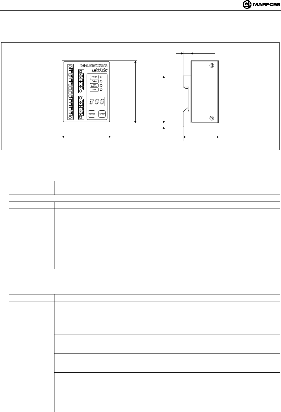
ESPAÑOL
E86N- Sistema touch con transmisión radio
200
9.2 Dimensiones unidad de la interfaz
Figura 9-2. Dimensiones.
9.3 Características técnicas Interfaz E86N
Alimentación : 24 VDC no estabilizada (13,5÷35 V)
: 300 mA máx. (con dos antenas conectadas)
Señales entrada : Entradas optoaisladas (24V - <10mA)
-AUX IN : No conectado (para usos futuros)
-SEL 0 - SEL 1 : Selección código de identificación para la selección de hasta 4 Transmisores en la misma máquina (véase
el párrafo 9.4.1“Selección del código de identificación” pág. 201).
24V - 7 mA
-START/STOP : Activación/Desactivación de la transmisión.
24V – 4mA (High current)
La tensión/corriente de trabajo de esta entrada puede programarse en relación al tipo de CN conectado
(véase el párrafo 10.1 “Programación de la interfaz” pág. 204) en los siguientes valores:
15V – 0,5 mA (Low current)
Nota: La conexión de las señales de entrada puede ser tipo SINK (conectar “COM” a la “+24V”) o bien tipo SOURCE
(conectar “COM” a la “0V”).
Señales Salida : Contactos Relé de Estado Sólido (SSR) 50V - 40 mA
-ERROR : Error de comunicación
(sonda no activada o fuera del campo de transmisión, batería transmisor completamente descargada con
nivel batería en pantalla igual a “0”.
Contacto siempre N.C. (Normal Cerrado)
-AUX OUT : No conectado (para usos futuros)
-PROBE 1/SKIP : Señal relacionada con el estado de la sonda utilizada; puede programarse como señal de estado sonda
(en reposo o desviada) o SKIP (impulso).
Contacto programable N.C. o N.A. (Normal Cerrado o Normal Abierto)
-PROBE 2/SKIP : Señal adicional relacionada con el estado de la sonda utilizada; puede programarse como señal de estado
sonda (en reposo o desviada) o SKIP (impulso).
Contacto programable N.C. o N.A. (Normal Cerrado o Normal Abierto)
-LOW BAT : Señal de batería casi descargada con nivel batería en pantalla igual a “3”.
Utilizando una batería alcalina el funcionamiento residuo continuado del sistema en esta condición es el
siguiente:
• 14 horas para el transmisor Estándar
• 24 horas para el transmisor Compacto
Contacto programable N.C. o N.A. (Normal Cerrado o Normal Abierto).
70
(2,76”)
51
(2,01”)
11
(0,43”)
68
(2,68”)
5,5
(0,22”)
90
(3,54”)
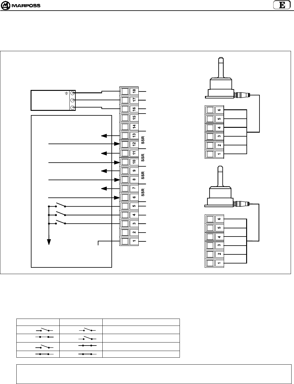
mida 201
9.4 Conexiones a la unidad de interfaz
En la tarjeta de la unidad hay un tablero de bornes de conexión; las conexiones se realizan por medio de conectores con acoplamiento
de rosca.
Figura 9-3. Conexiones.
9.4.1 Selección del código de identificación
Entrada procedente de lógica:
SEL 0 SEL 1 CÓDIGO DE IDENTIFICACIÓN
I1 I2 A
I1 I2 B
I1 I2 C
I1 I2 D
Nota: En caso de que se utilice solo un transmisor NO es necesario administrar estas 2 Entradas procedentes del CNC.
La interfaz, por defecto, está programada en el código de identificación A, así como el transmisor (véase el párrafo
10.2“Programación del Transmisor” pág. 207).
VERDE
AZUL
BLANCO
VIOLET
A
PANTALLA
ROJO
ANTENA 1
ANTENA 2
VERDE
AZUL
BLANCO
VIOLET
PANTALLA
ROJO
COM
A
UX IN
SEL 0
SEL 1
START/STOP
ESTADO SONDA
SKIP
ESTADO SONDA
SKIP
BATERÍA
DESCARGADA
ERROR
A
UX OUT
+24V DC
0V
TIERRA
CNC CONTROL MÁQUINA
0V SOURCE
24V SINK
ESTADO SONDA 1/ SKIP
ESTADO SONDA 2/ SKIP
BATERÍA DESCARGADA
ERROR
24V
0V
UNIDAD DE
ALIMENT.
I1
I2
24V SOURCE
0V SINK
(
H1
)
(
H2
)
(
I
)

ESPAÑOL
E86N- Sistema touch con transmisión radio
202
9.5 Diagrama I/O unidad de interfaz E86N
Figura 9-4. Diagrama I/O unidad de Interfaz.
NOTA: en algunos entornos de trabajo con muchas interferencias electromagnéticas, el tiempo necesario para activar la
transmisión puede ser superior a 1 segundo (máx 6).
Abierto
Cerrado
A
bierto
Cerrado
A
bierto
Cerrado
A
bierto
Cerrado
A
bierto
Cerrado
A
bierto
Cerrado
A
bierto
Cerrado
Estado
Sonda
Estado
Sonda
Skip
Skip
Batería
descargada
Batería
descargada
Error
Señales
E86N
relé
estado
sólido
Start
Sonda activada
En reposo
A
pertura contacto
Desviada
Cierre contacto
En reposo
Erro
r
Error eliminado
Batería descargada
Sonda desactivada
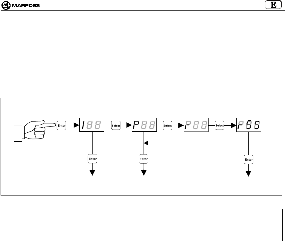
mida 203
10. PROGRAMACIÓN DEL SISTEMA
Manteniendo presionada durante más de 2 segundos la tecla “Enter”, el sistema entra en el modo programación. A continuación hay
que escoger el tipo de programación por medio de la tecla “Select”:
I --> Programación de la Interfaz
P --> Programación del Transmisor
r --> Programación del Transmisor en el modo "Recovery"
rSS ÆProgramación de la función “Sniffer”
Cuando se haya efectuado la selección, a través de las teclas “Select” y “Enter” se modifican los datos de programación. La tecla
“Select” incrementa el dato de programación actual mientras que la tecla “Enter” lo confirma y pasa al siguiente.
ATENCIÓN: En el caso de que se desee volver a programar solo el Canal de funcionamiento, hay que iniciar el procedimiento
empezando por la programación del Transmisor.
De esta manera, puesto que la Interfaz se suministra con la función Programación automática del canal habilitada
(AP=1 – véase el párrafo 10.1 “Programación de la interfaz”), al final de la reprogramación del canal de
funcionamiento en el transmisor, también la Interfaz se programa automáticamente en el mismo canal.
PROGRAMACIÓN DEL
TRANSMISOR
PROGRAMACIÓN DE
LA INTERFAZ
PROGRAMACIÓN DEL
TRANSMISOR EN MODO
RECOVERY
> 2 segundos
PROGRAMACIÓN DE LA
FUNCIÓN “SNIFFER”
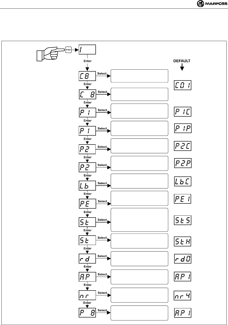
ESPAÑOL
E86N- Sistema touch con transmisión radio
204
10.1 Programación de la interfaz
Entrando en el modo de programación y seleccionando el tipo de programación "I", a través de las teclas “Select” y “Enter”, se pueden
modificar uno a uno los siguientes valores:
Nota: después de la confirmación del último dato se sale de la programación.
Se puede salir en cualquier momento, presionando durante más de 2 segundos la tecla <ENTER>, anulando la secuencia
actual.
Inserción de los canales:
DECENAS
Inserción de los canales:
UNIDADES
Polaridad salida probe 1:
P1C= SALIDA N.C.
P1O= SALIDA N.O.
Funcionalidad salida probe 1:
P1P= PROBE STATUS
P1S= SKIP
Modo salida LOW BAT:
LbC= N.C.
LbO= N.O.
Salida PROBE en error:
PE0= Probe a 0 (reposo)
PE1= Probe a 1(desviado)
Señal START:
S= Estándar
P= Pulse
r= rettirgger
Pantalla a distancia en estac.base:
0= inhabilitada
1= habilitada
Entrada START:
L= baja corriente 15V-0,5mA
H= corriente normal 24V-4mA
Progr. automática canal:
0= inhabilitada
1= habilitada
Confirmación programación:
0= no confirmada
1= confirmada
Polaridad salida probe 2:
P2C= SALIDA N.C.
P2O= SALIDA N.O.
Funcionalidad salida probe 2:
P2P= PROBE STATUS
P2S= SKIP
> 2 segundos
Número de intentos de
activación/desactivación
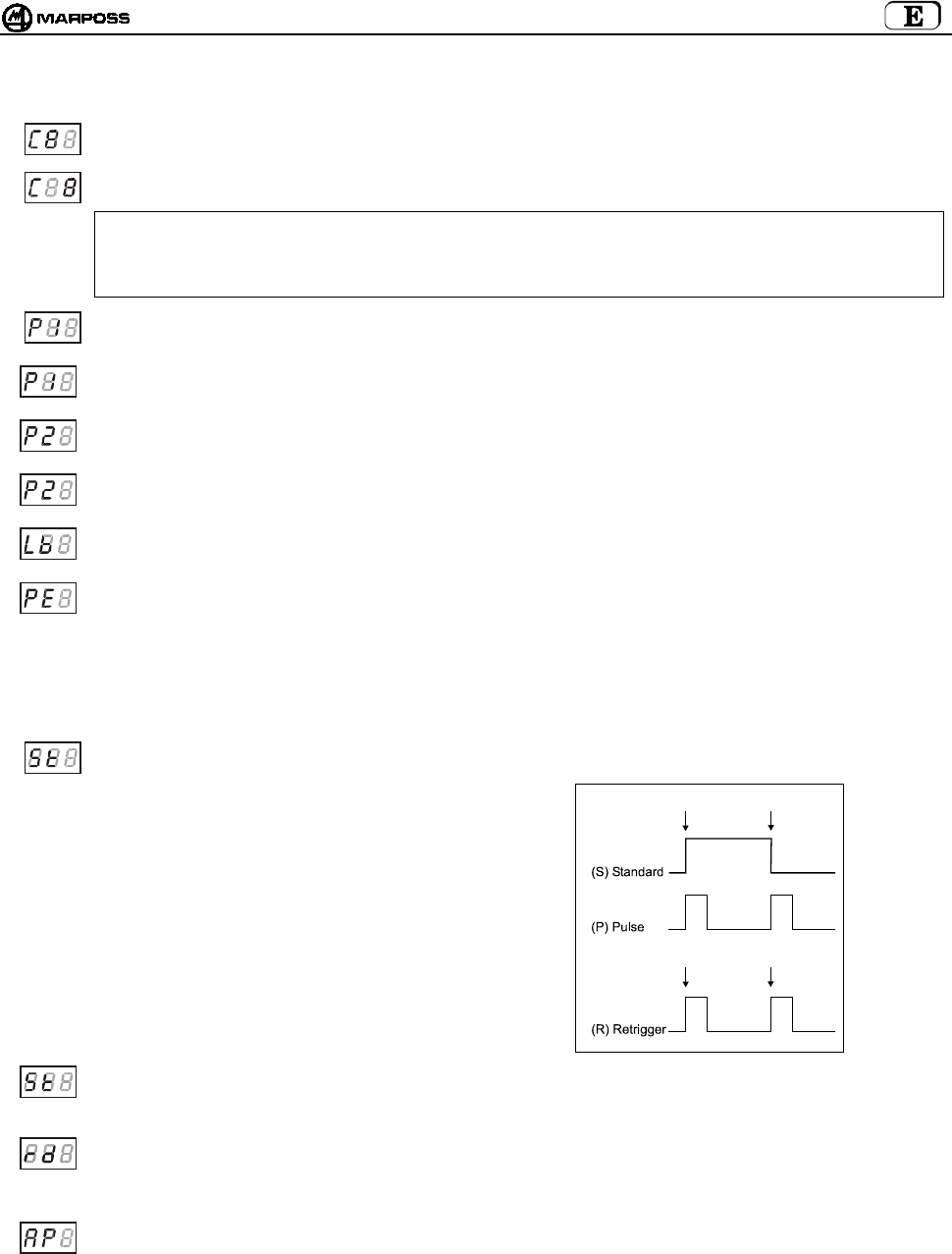
mida 205
A continuación, la descripción detallada de los datos de programación de la Interfaz:
Canal de transmisión de la interfaz – decenas: parpadea el campo decenas, que es incrementado cíclicamente por
el botón “Select”.
Canal de transmisión de la interfaz – unidades: parpadea el campo unidades, que es incrementado cíclicamente por
el botón “Select”.
ATENCIÓN:
Tras la confirmación de la programación (P1), la selección errónea de los canales 65-69 o 00 no se considera válida y
la pantalla de la interfaz parpadea en el canal erróneo recién programado. Para salir de esta condición, es suficiente
volver a entrar en el modo de programación de la interfaz y programar el canal correcto (de 1 a 64).
Polaridad de la salida PROBE1: las primeras cifras indican “P1”. La tercera asume cíclicamente los valores <C> y
<O> que indican NORMAL CERRADO y NORMAL ABIERTO.
Funcionalidad de la salida PROBE1: las primeras cifras indican “P1”. La tercera asume cíclicamente los valores ‘P’ y
‘S’ que indican salida normal o tipo “skip” (impulso de la duración de 44ms a cada cambio de estado del touch).
Polaridad de la salida PROBE2: las primeras cifras indican “P2”. La tercera asume cíclicamente los valores <C> y
<O> que indican NORMAL CERRADO y NORMAL ABIERTO.
Funcionalidad de la salida PROBE2: las primeras cifras indican “P2”. La tercera asume cíclicamente los valores <P>
y <S> que indican salida normal o tipo “skip” (impulso de la duración de 44ms a cada cambio de estado del touch)
Polaridad de la salida LOW_BAT: las primeras cifras indican “lb” La tercera asume cíclicamente los valores <C> y
<O> que indican normal cerrado y normal abierto.
Salida Probe en error: permite programar el estado que asumen las salidas PROBE1 y PROBE2 en condiciones de
error:
- transmisor no activado
- transmisor fuera de campo
- batería completamente descargada
Las primeras cifras indican “PE”. La tercera asume cíclicamente los valores <0> (probe en reposo) y <1> (probe
desviada).
Modo de funcionamiento señal Start: las primeras cifras indican “St”. La tercera asume cíclicamente los valores ‘S’
(estándar), ‘P’ (Pulse) y ‘r’ (retrigger).
En el modo “estándar” el frente de subida activa
la sonda y el frente de bajada la desactiva.
En el modo “pulse” el frente de subida hace
cambiar el estado de la sonda, si está
desactivada se activa y si está activada se
desactiva.
Para finalizar en el modo “retrigger” se excluye
la posibilidad de desactivar la sonda vía radio, y
un frente de subida en la señal Start cuando la
sonda todavía está activada, causa el retrigger
del temporizador del transmisor. De este modo
el apagado del transmisor puede efectuarse
únicamente a través del temporizador.
Corriente de la entrada Start: las primeras cifras indican “St”. La tercera asume cíclicamente los valores ‘L’ (Low
current) y ‘H’ (High current). En el modo “low current” la entrada absorbe unos 0.5mA a 15V (*Nota). En el modo “high
current ” la entrada es estándar y absorbe unos 4mA a 24V.
Pantalla a distancia Antena: las primeras cifras indican “rd”. La tercera asume cíclicamente los valores <0>
(inhabilitado, los led de la estación base indican el nivel de la señal radio) y <1> (habilitado, los led de la estación base
presentan la indicación de los led en la interfaz, salvo el led verde central de la estación base que está siempre
apagado) (véase 8.2 “Modo pantalla a distancia” pág. 197.
Programación automática del canal de la interfaz: las primeras cifras indican “AP”. La tercera asume cíclicamente
los valores <0> (inhabilitada, la programación del canal del transmisor no afecta el valor programado de la interfaz) y
<1> (habilitada, al final de la programación del transmisor el canal de la interfaz es alineado al canal que se está
programando en el transmisor (véase el párrafo 10.2“Programación del Transmisorp” pág. 207).
*Nota: Esta funziòn vieme habilitada com la alargo cod.6739696319.
Activación
Activación
Desactivación
Retrigger
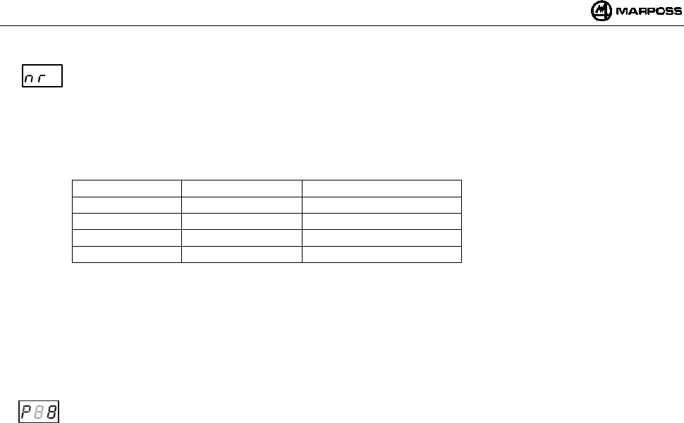
ESPAÑOL
E86N- Sistema touch con transmisión radio
206
Número de intentos de activación/desactivación : las 2 primeras cifras indican la palabra “nr”.
la tercera asume cíclicamente los valores de 2 a 9 (valor por defecto 4).
este dato permite programar el número de intentos máximos que la estación básica ejecuta para la
activación/desactivación del transmisor al alcanzar dichos intentos. en caso de que el transmisor no se haya
activado/desactivado, hay que suministrar a la interfaz un nuevo mando por medio de la señal de inicio.
el aumento del número de intentos conlleva un mayor retraso en el tiempo de activación/desactivación.
para el valor por defecto (nr=4) los tiempos de activación/desactivación son tal como ilustra la tabla:
TÍPICO VALOR MÁX CÓDIGO IDENTIFICACIÓN
1,050 seg 4,200 seg A
1,200 seg 4,800 seg B
1,350 seg 5,400 seg C
1,500 seg 6,000 seg D
al variar el número de intentos, los valores de la tabla se modifican según la relación:
delay = defecto delay x (nr / 4)
tal como indica la tabla, el tiempo de activación/desactivación depende también del código de identificación utilizado
(subcanal).
cuanto mayor es la distancia entre códigos, menor será la probabilidad de fracaso de activación/desactivación, en
situaciones de alta densidad de aplicaciones próximas.
Confirmación de datos programados: La primera cifra indica “P”. La tercera asume cíclicamente los valores <0> para
no programar la Interfaz y <1> para programarla.
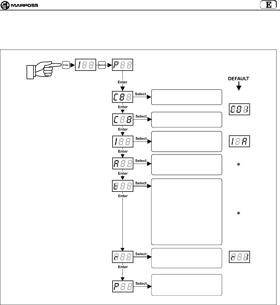
mida 207
10.2 Programación del Transmisor
Entrando en el modo de programación y seleccionando el tipo de programación "P", a través de las teclas “Select” y “Enter”, se pueden
modificar uno a uno los siguientes valores:
Nota: después de la confirmación del último dato se sale de la programación y el transmisor se desactiva.
Se puede salir en cualquier momento, presionando durante más de 2 segundos la tecla <ENTER>, anulando la
secuencia actual.
(
∗
) Nota: depende del tipo de transmisor:
- en el caso de transmisor con activación radio, el parámetro modo de activación se programará en activación radio y el
tiempo de apagado en el valor <5> que corresponde a 2'14".
- En el caso de activación mecánica, el parámetro modo de activación se programará en activación mecánica y el
tiempo de apagado en el valor <8> que corresponde a tiempo de apagado infinito.
Inserción de los canales:
DECENAS
Inserción de los canales:
UNIDADES
Código identificación:
(A, B, C, D)
Modo activación:
0= Radio
1= Mecánica
Tiempo de funcionamiento:
0= 4"
1= 8"
2= 17"
3= 34"
4= 1'7"
5= 2'14"
6= 4'28"
7= 8'57"
8=
∞
Rettrigger del Temporizador:
0= Inhabilitado
1= Habilitado
Confirmación programación:
0= no confirmación
1= confirmación
> 2 segundos
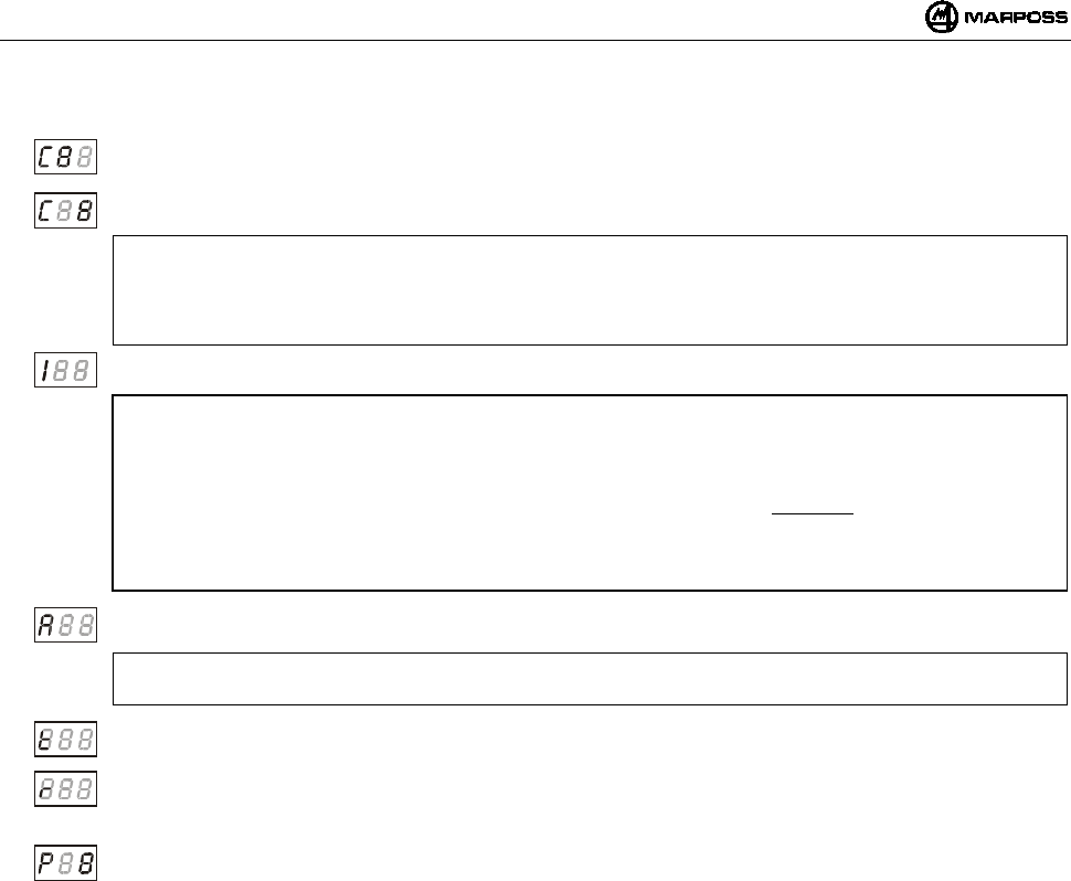
ESPAÑOL
E86N- Sistema touch con transmisión radio
208
A continuación, la descripción detallada de los datos de programación del Transmisor:
Canal de transmisión – decenas:
parpadea el campo decenas, que se incrementa cíclicamente del valor <0> al valor <6>.
Canal de transmisión – unidades: parpadea el campo unidades, que se incrementa cíclicamente del valor <0> al
valor <9>.
ATENCIÓN:
Tras la confirmación de la programación (P1) , la selección errónea de los canales 65-69 o 00 no se considera válida,
en la pantalla de la interfaz parpadea el canal donde está programada la interfaz misma y el transmisor puede
restablecerse solo en el modo “recovery” (véase 10.3 “Programación del transmisor en el modo Recovery” pág. 209).
Código de identificación: la primera cifra indica “I” la tercera puede seleccionarse entre los valores <A, B, C, D>.
ATENCIÓN:
Un Transmisor está completamente identificado por el número de canal de mecanizado y por el código de identificación
(ej. 12B).
Puesto que el código de identificación puede programarse para el Transmisor pero es una entrada desde lógica externa
(CNC) para la Interfaz, es aconsejable modificar este parámetro en el Transmisor solamente si es seguro que es igual
que el de la Interfaz; en caso contrario el equipo no funcionará por falta de comunicación y el único modo para
restablecerlo será efectuando un proceso de programación del transmisor en el modo “Recovery” (véase 10.3
“Programación del transmisor en el modo Recovery” pág. 209).
Modo de activación: la primera cifra indica “A” La tercera asume cíclicamente los valores <0> para activación radio y
<1> para activación mecánica;
ATENCIÓN:
dejar el valor por defecto indicado en la página anterior.
Tiempo de funcionamiento: la primera cifra indica “t”. La tercera debe programarse con un valor entre <0 y 8>,
correspondiente a un tiempo de funcionamiento desde un mínimo de 4” (valor 0) a infinito (valor 8).
Retrigger del temporizador: la primera cifra indica “r”. La tercera asume cíclicamente los valores <0> para retrigger
inhabilitado y <1> para retrigger habilitado.
Este dato, permite la puesta a cero del temporizador después de cada cambio de estado de la sonda.
Confirmación de los datos programados. La primera cifra indica “P”. La tercera asume cíclicamente los valores <0>
para no programar el Transmisor y <1> para programarlo.
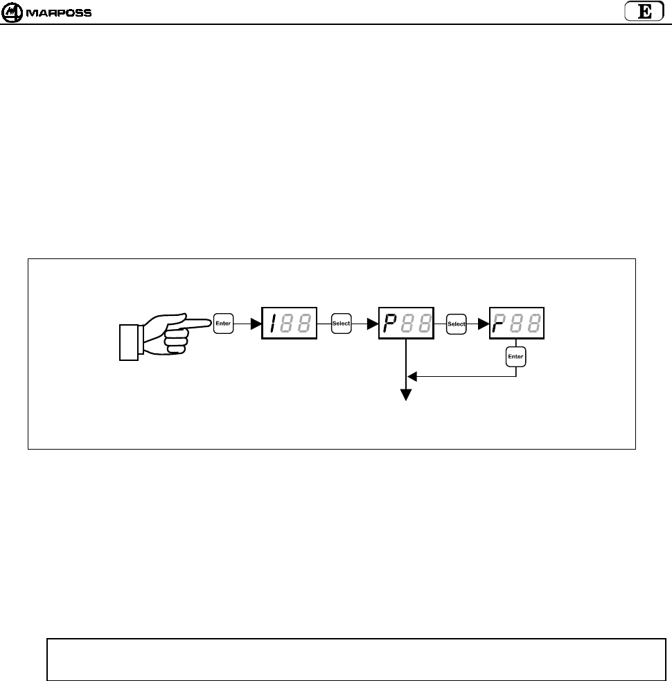
mida 209
10.3 Programación del transmisor en el modo Recovery
En caso de que el Transmisor se halle en una de las siguientes condiciones:
a. canal de transmisión del transmisor desconocido
b. programación errónea del canal de transmisión (ej. 65-69 o 00)
c. programación errónea del código de identificación (diferente al de la Interfaz)
está previsto un procedimiento de programación del Transmisor llamado “recovery”, que permite remontarse a los parámetros del
Transmisor y modificarlos.
El procedimiento se efectúa de la siguiente manera:
1. dejando la Interfaz con alimentación, desactivar la alimentación del Transmisor (desenroscar la tapa de las baterías en caso
de transmisor con activación radio o abrir el microinterruptor en el cono en caso de transmisor con activación mecánica);
2. desde la Interfaz entrar en el modo de programación y seleccionar el tipo de programación "r";
3. presionando la tecla <ENTER> en la pantalla se visualiza el mensaje "REC";
4. Desviar el brazo y mantenerlo así mientras se suministra alimentación al transmisor (cerrar la tapa de las baterías en caso de
transmisor con activación radio o cerrar el microinterruptor en el cono en caso de transmisor con activación mecánica);
5. El transmisor se activa en un canal de servicio en lugar del canal programado y en la pantalla de la interfaz desaparece el
mensaje “REC” y se visualiza el número del canal (con decenas intermitentes) donde se había programado el transmisor;
6. Soltar el brazo manteniendo alimentado el Transmisor (tapa cerrada/microinterruptor en el cono cerrado)
A continuación, cuando se haya conseguido la información deseada, se puede
• Salir de la programación
Presionando durante más de 2 segundos la tecla <ENTER> o sencillamente soltando la tapa/microinterruptor.
• Efectuar una programación corriente del transmisor tal como se menciona en el párrafo 10.2 “Programación del Transmisorp”
pág. 207.
ATENCIÓN: Si en la Interfaz está habilitada la “programación automática del canal” (AP=1 – véase el párrafo 10.1
“Programmazione dell'interfaccia”), al final de la programación del transmisor, también el canal de la
Interfaz cambia, alineándose al que está presente en el Transmisor mismo.
> 2 segundos
PROGRAMACIÓN DEL
TRANSMISOR
(
véase el
p
árrafo 10.2
)

ESPAÑOL
E86N- Sistema touch con transmisión radio
210
10.4 Análisis ocupación del espectro electromagnético (función “Sniffer”)
El análisis de la ocupación del espectro electromagnético se desarrolla en dos fases
• Exploración
La interfaz E86N ejecuta cíclicamente la exploración de los 64 canales, memorizando por cada canal la amplitud máxima de la
señal recibida;
• Visualización de los resultados
La interfaz E86N visualiza los canales y la amplitud máxima memorizada durante la exploración anterior.
Para activar la función hay que colocar la interfaz en el “Modo Programación” (presionando “Enter” durante más de 2 segundos),
presionar varias veces la tecla “Select” hasta que en pantalla aparezca la palabra “rSS” y a continuación presionar “Enter”.
XX XX XX XX
> 2 segundos
> 2 segundos > 2 segundos > 2 segundos > 2 segundos
Enter=Lista ▲
Select= Lista ▼
Enter=Lista ▲
Select= Lista ▼
Enter=Lista ▲
Select= Lista ▼

mida 211
10.4.1 Exploración
Presionar “Select” hasta que en pantalla aparezca “St” (Start).
Presionando “Enter” se activa la exploración que continúa hasta que se vuelva a presionar la tecla “Enter” durante más de 2 segundos.
La exploración puede estar activada durante largo tiempo.
Durante la exploración la tecla “Select” no está activa.
En la pantalla aparecen en secuencia:
• el número del canal adquirido “Cnn” (nn= número del canal 01-64, además del canal de activación “CA”)
• la correspondiente amplitud de la señal “XX”.
La amplitud de la señal se expresa en escala logarítmica y puede variar de –9 a 99 (véase la tabla de abajo).
NIVEL SEÑAL VALOR VISUALIZADO LED ESTACIÓN BÁSICA
límite bajo ≤ -1
mucho bajo (1) 0 / 3
bajo 4 / 7
medio 8 / 11
arriba ≥ 12
NOTAS:
1. El valor <0> corresponde al mínimo nivel de señal considerado “comprensible” (Amplitud –102dBm y relación Señal/Ruido > -
12dB).
2. Cuando está activa la función de exploración se deshabilitan todas las demás funciones. (El estado de las salidas del E86N
está como en condición de error).
3. Los valores máximos adquiridos se memorizan en una memoria no retentiva y por lo tanto se pierden en el apagado.
4. Cuando se activa una exploración los anteriores valores máximos adquiridos se borran.
5. El tiempo de exploración es aproximadamente de 1 segundo por canal y por consiguiente una exploración completa requiere
unos 70 segundos. Puesto que el sistema está habilitado para adquirir sólo un canal a la vez, la probabilidad de localizar
señales electromagnéticas de breve duración aumenta alargando el período de observación.
6. Los valores adquiridos están disponibles sólo después de que se haya efectuado por lo menos una exploración completa.
7. Si las estaciones básicas son dos se utiliza el mayor de los dos datos adquiridos.
10.4.2 Visualización de los resultados
Los resultados de una exploración pueden visualizarse con tres diferentes tipos de clasificación:
Símbolo Clasificación Primer elemento de la lista
HI Señal recibida decreciente Canal en el que se ha recibido la señal de amplitud máxima
LO Señal recibida creciente Canal en el que se ha recibido la señal de amplitud mínima
CH Número canal creciente Canal 00
Para visualizar los resultados presionar “Select” hasta que en la pantalla aparezca el símbolo correspondiente a la clasificación
deseada y luego presionar la tecla “Enter”.
En la pantalla se visualiza antes el número del canal y luego el valor de la señal.
• Presionando la tecla “Enter” se pasa al elemento siguiente de la lista hasta llegar al último elemento.
• Presionando la tecla “Select” se vuelve al elemento anterior, hasta llegar al primer elemento.
• Presionando la tecla “Enter” durante más de 2 segundos se sale de la exploración de la lista.
Rojo
Amarillo
Verde
Verdes
Verdes
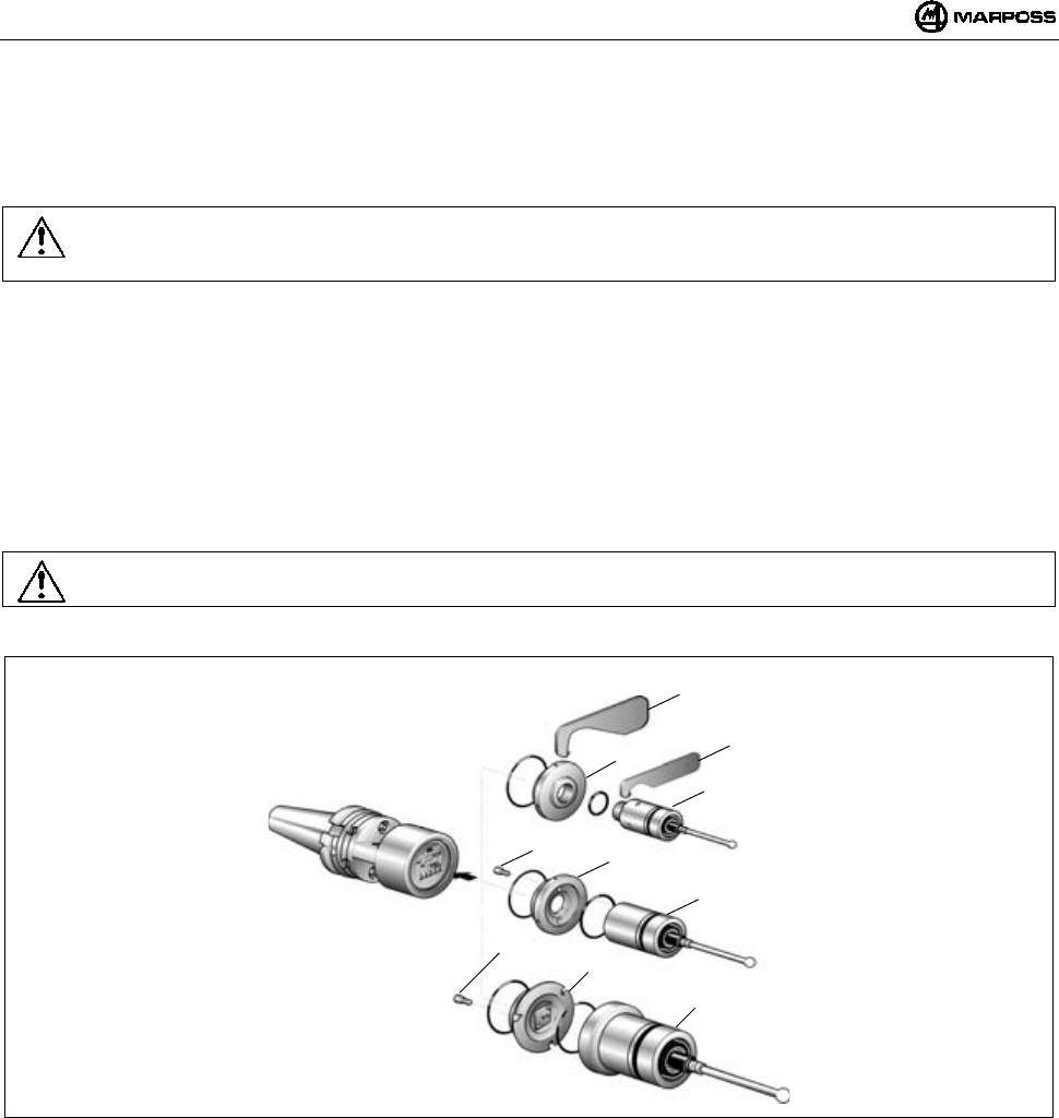
ESPAÑOL
E86N- Sistema touch con transmisión radio
212
11. INSTALACIÓN SONDA – TRANSMISOR ESTÁNDAR
11.1 Instalación sonda – transmisor estándar
Para la instalación o la desinstalación de la sonda del transmisor proceder de la siguiente manera:
Advertencia:
En la fase de instalación de la sonda es aconsejable asegurarse que los anillos de estanqueidad estén en las mejores
condiciones y posicionados correctamente en su alojamiento.
SONDA T25/TL25/TT25
- enroscar la brida (A) al transmisor, por medio de la llave correspondiente (A1).
- enroscar la sonda, a la brida (A) utilizando la llave suministrada con el equipo (A2).
SONDA T36
- fijar la sonda a la brida (B) por medio de los tornillos (B1);
- Enroscar la brida (B) al transmisor utilizando la llave suministrada con el equipo
SONDA T60/TT60
- fijar la sonda a la brida (C) por medio de los tornillos (C1);
- Enroscar la brida (C) al transmisor utilizando la llave suministrada con el equipo;
Advertencia:
Al final de la operación ejecutar la alineación del sistema.
Figura 11-1
A
1
A
T25/TL25/TT25
B1 B
T36
C1
C
T60/TT60
A
2
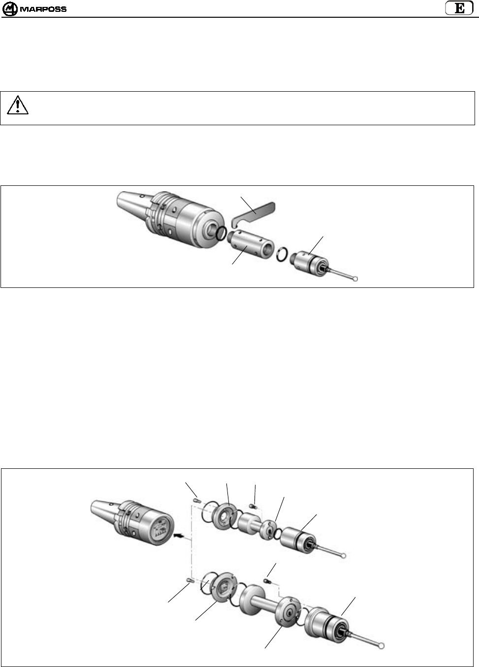
mida 213
11.2 Inserción prolongaciones para sondas (opcionales)
La prolongación se introduce entre sonda y transmisor para aumentar la profundidad de medida del sistema. Para la inserción de las
prolongaciones proceder de la siguiente manera.
Advertencia:
En la fase de inserción de la prolongación es aconsejable asegurarse que los anillos de estanqueidad estén en las mejores
condiciones y posicionados correctamente en su alojamiento.
• Prolongación para sonda T25/TL25/TT25
- Retirar la sonda del transmisor con la llave correspondiente (A1) suministrada con el equipo.
- Interponer entre la sonda y el transmisor la prolongación (A2) con los relativos anillos de estanqueidad.
- Ajustar el grupo con la llave (A1) suministrada con el equipo.
Figura 11-2
• Prolongación para sonda T36
- Desenroscar la brida (B) del transmisor.
- Retirar la sonda de la brida (B) sacando los tornillos (B1).
- Fijar la prolongación (B2) a la brida (B) por medio de los tornillos (B1).
- Enroscar el grupo brida/prolongación, al transmisor con la llave suministrada con el equipo
- Fijar la sonda a la prolongación por medio de los tornillos (B3).
• Prolongación para sonda T60/TT60
- Desenroscar la brida (C) del transmisor.
- Retirar la sonda de la brida (C) sacando los tornillos (C1).
- Fijar la prolongación (C2) a la brida (C) por medio de los tornillos (C1).
- Enroscar el grupo brida/prolongación, al transmisor con la llave suministrada con el equipo
- Fijar la sonda a la prolongación por medio de los tornillos (C3).
Figura 11-3
A
2
A
T25/TL25/TT25
C3
B1
T36
T60/TT60
BB3
B2
C1
C
C2
C3

ESPAÑOL
E86N- Sistema touch con transmisión radio
214
12. INSTALACIÓN DEL TRANSMISOR
12.1 Instalación del transmisor Estándar en el cono
- Retirar las tapas batería (C) del transmisor - tornillos (D) - para acceder a los cuatro orificios (E) en la brida. La fijación con
brida estándar puede efectuarse de dos distintas maneras:
- Efectuar en el cono cuatro orificios roscados M4x8 (A) y una avellanadura central (B) como indica la Figura 12-1.
- Insertar entre el transmisor y el cono la esfera (G) ø6 mm suministrada con el equipo.
- Fijar el transmisor al cono por medio de los cuatro tornillos (F).
Alineación del sistema
- Instalar el brazo sonda (véase "Instalación brazo sonda").
- Alinear el centro de la esfera del brazo al eje del cono interviniendo en los cuatro tornillos (F).
- Cuando se haya alineado el sistema, ajustar los cuatro tornillos (F) con secuencia de cruz.
Figura 12-1
D
C
D
C
F
E
F
34
(1,34”)
34
(1,34”)
4,5
±
0,1 mm
(0,177 ± 0,004)
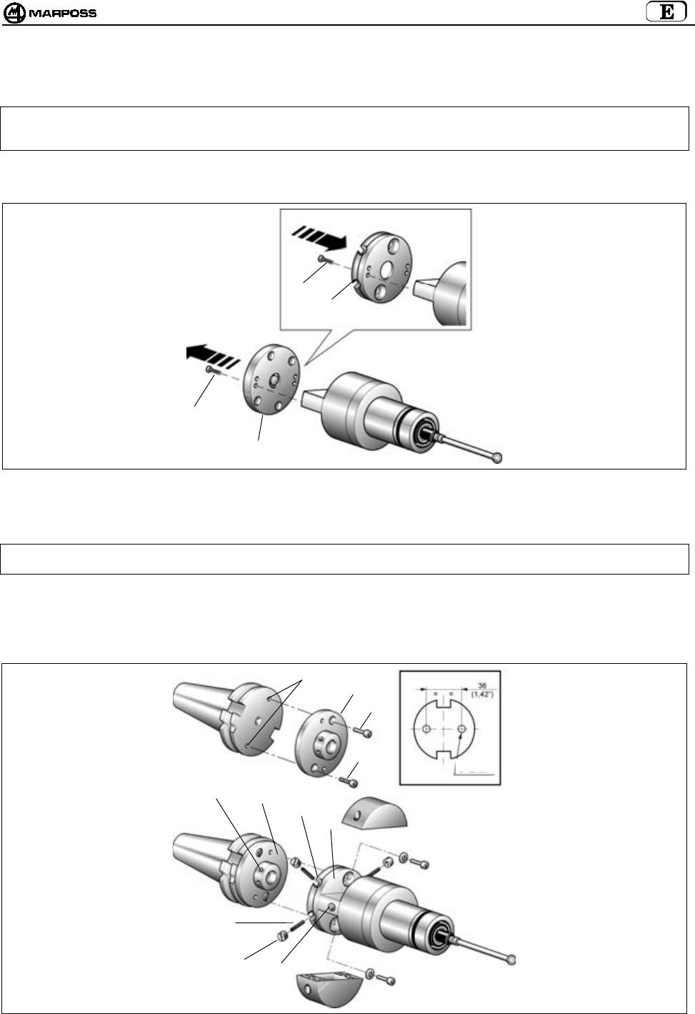
mida 215
12.2 Instalación transmisor Estándar en el cono con brida de regulación
1. Retirar las tapas batería del transmisor quitando los tornillos (véase el cap.12.1).
Nota: Las operaciones mencionadas en los puntos 2 - 3 - 4 y 5 son válidas solo con transmisor con activación radio. El
transmisor con activación mecánica (microinterruptor en el cono) se suministra, con cono portaherramientas, con
bridas de regulación previamente instaladas. En este caso continuar desde el punto 6.
2. Retirar la brida estándar (C) del transmisor quitando los cuatro tornillos (D).
3. Fijar al transmisor la brida de regulación (E) por medio de los cuatro tornillos (D).
Figura 12-2
4. Efectuar en el cono portaherramientas dos orificios roscados M4x8 (F).
5. Fijar al cono portaherramientas la brida de regulación (G) por medio de los dos tornillos (H).
Nota: Para facilitar la orientación del LED (L) del transmisor hacia el operador, están disponibles tres pares de orificios de
fijación que permiten seleccionar la posición angular más adecuada.
6. Juntar los dos grupos (transmisor-cono) haciendo coincidir los cuatro orificios roscados (M) de la brida cono (G) con los
cuatro ojales (N) de la brida transmisor (E).
7. Insertar los cuatro espárragos roscados (P) en los ojales (N) y enroscarlos en los orificios roscados (M) de la brida cono por
medio de la llave hexagonal suministrada con el equipo.
8. Enroscar las cuatro tuercas especiales (Q) en los espárragos.
Figura 12-3
C
D
D
E
P
QL
MG
N
E
F
G
H
H
F=M4x8
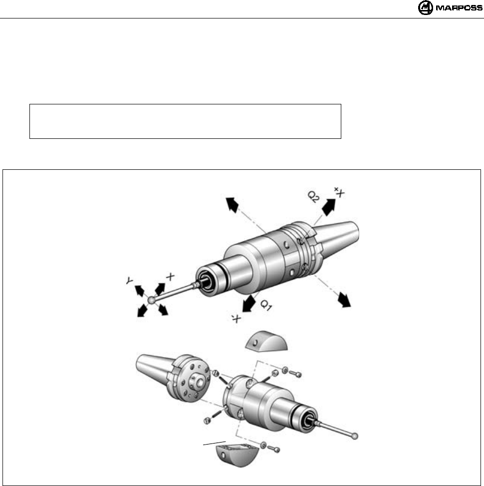
ESPAÑOL
E86N- Sistema touch con transmisión radio
216
Alineación del sistema
9. Instalar el brazo sonda (véase "Instalación del brazo sonda").
10. Alinear el centro de la esfera del brazo al eje del cono interviniendo en las cuatro tuercas especiales (Q). Máxima traslación
admitida: 1,7 mm en las cuatro direcciones.
Ejemplo:
Traslación de la esfera brazo hacia "-X" —> aflojar (Q1) y enroscar (Q2).
Proceder de la misma manera para las demás direcciones.
11. Cuando se haya alineado el sistema proceder con el bloqueo del grupo de regulación; insertar y ajustar los dos tornillos (R) de
bloqueo.
Figura 12-4
R
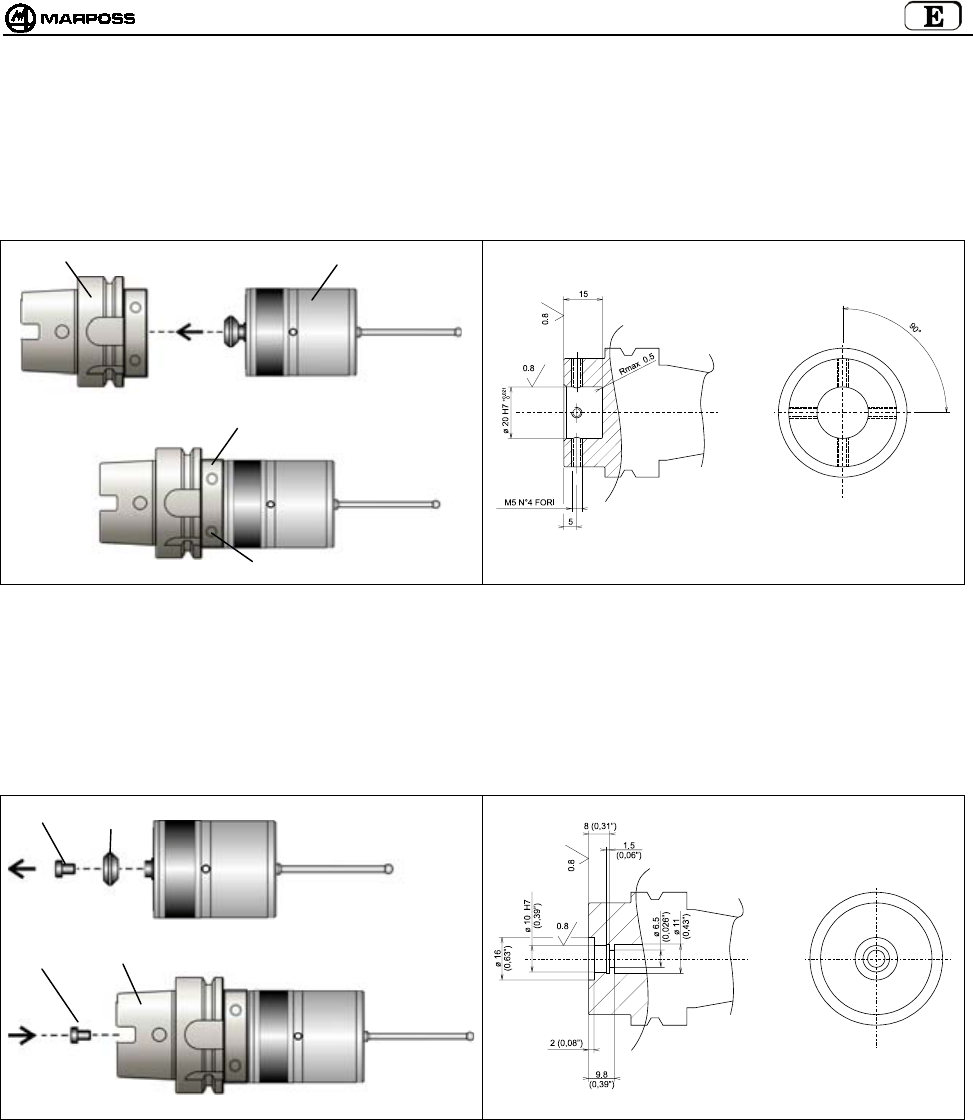
mida 217
12.3 Instalación transmisor compacto E86N-P en el cono
12.3.1 Fijación transmisor E86N-P al cono (mecanizado del cono)
• Insertar el cono (A) en el Transmisor (B).
• Fijar el Transmisor al cono por medio de 4 pasadores en los orificios (C).
Figura 12-5. Fijación del transmisor al cono. Figura 12-6. Mecanizado del cono.
12.3.2 Fijación al cono del transmisor E86N-P sin mango cónico (mecanizado del cono)
• Desenroscar el tornillo (A) que fija el mango cónico al transmisor (B).
• Insertar el cono (C) en el Transmisor (B).
• Fijar el Transmisor por medio del tornillo (A).
Figura 12-7. Fijación del transmisor al cono Figura 12-8. Mecanizado del cono.
A
B
C
C
AB
C
A

ESPAÑOL
E86N- Sistema touch con transmisión radio
218
13. INSTALACIÓN DEL BRAZO
A continuación se explica el procedimiento de instalación del brazo en la sonda instalada en un Transmisor Estándar, pero puesto que
el Transmisor Compacto incorpora la sonda y el portabrazo es idéntico, el procedimiento es el mismo para ambos tipos de transmisor.
Para la instalación del brazo en la sonda proceder de la siguiente manera:
Nota: El procedimiento siguiente prevé el empleo de la clavija de rotura. Dicha clavija, colocada entre el brazo y la sonda,
se encarga de proteger la sonda en caso de golpes accidentales en el brazo (se realiza la separación del brazo de la
sonda).
- Insertar la clavija de rotura (A) en la sonda (B).
- Con la llave (suministrada con el equipo) sujetar el portabrazo (C) de la sonda y con la otra llave, ajustar la clavija de rotura (A). La
llave para ajustar la clavija (A), debe insertarse en la parte inferior de la clavija misma - posición (D).
- Enroscar el brazo (F) en la clavija de rotura (A).
- Con una llave sujetar la clavija y con la otra, ajustar el brazo.
- Insertar el retén (E), deslizándolo a lo largo del brazo mismo hasta envolver la clavija de rotura (A). Este retén se encarga de
sujetar el brazo, en caso de rotura de la clavija.
- En las aplicaciones por radio es aconsejable utilizar brazos de cerámica y no de acero, para evitar supuestas interferencias (poco
probables). En caso de que no se utilice la clavija de rotura enroscar el brazo directamente en la sonda; con una llave sujetar el
portabrazo (C) y con la otra ajustar el brazo.
Figura 13-1
A
B
F
A
A
DC
E
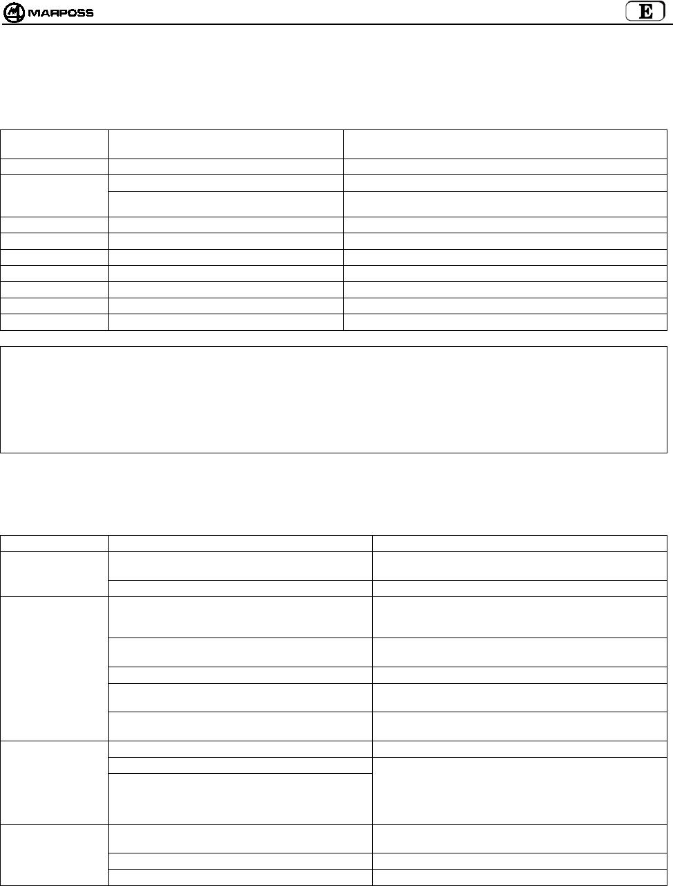
mida 219
14. DIAGNÓSTICO
14.1 Mensajes de error
En la pantalla de la unidad de Interfaz E86N pueden aparecer los siguientes mensajes de Error:
MENSAJE DE
ALARMA
CAUSA SOLUCIÓN
E.E2 Error de lectura/escritura Contactar Asistencia técnica o programar de nuevo todos los Datos.
E.nb Ninguna Antena conectada Comprobar conexión con Antena.
Errónea conexión de la antena Comprobar que en caso de una sola Antena, esté conectada en el borne
inferior (H1) de la Interfaz.
E.b1 Error de comunicación con Antena 1 Comprobar conexión con Antena 1.
E.b2 Error de comunicación con Antena 2 Comprobar conexión con Antena 2.
F.P1 Fallo (cortocircuito) en salida PROBE 1 Comprobar conexión en salida PROBE 1.
F.P2 Fallo (cortocircuito) en salida PROBE 2 Comprobar conexión en salida PROBE 2.
F. Er Fallo (cortocircuito) en salida ERROR Comprobar conexión en salida ERROR.
F. Lb Fallo (cortocircuito) en salida LOW_BAT Comprobar conexión en salida LOW_BAT.
F. Au Fallo (cortocircuito) en salida AUX Comprobar conexión en salida AUX.
Nota: Tras haber eliminado las causas del error, las señalizaciones pueden borrarse de la pantalla presionando simultáneamente
las teclas <Select> y <Enter> durante más de 2 segundos (salvo los mensajes E.b1 y E.b2 que se restablecen
suministrando alimentación).
ATENCIÓN:
Todas las operaciones de encendido o apagado del sistema, deben ejecutarse con el/los conector/es de la Antena
conectado/s.
14.2 Señalización de los Led
Los led presentes en el panel de la Unidad de Interfaz pueden señalizar:
CAUSA SOLUCIÓN
Ausencia de alimentación Comprobar que en los cabos de los bornes 16 y 17 del
tablero de bornes de la unidad de interfaz haya tensión.
LED "POWER"
APAGADO
Fusible de restablecimiento abierto Esperar unos minutos con interfaz no alimentada.
Transmisor- Antena fuera de campo de transmisión Asegurarse que durante los movimientos de la sonda el
led verde ""tuning"" presente en el receptor permanezca
encendido.
Batería transmisor totalmente descargada o
ausente
Reemplazarla
Tiempo de transmisión caducado Suministrar una señal de start para reactivar el sistema.
Ausencia de conexión eléctrica entre antena e
Interfaz
Comprobar el cable del receptor y las relativas
conexiones a la interfaz.
LED "ERROR"
ENCENDIDO"
Hay interferencia eléctrica o electromagnética Alejar el cable procedente de la antena de supuestos
cables de potencia. Cambiar canal de trabajo.
No hay conexión eléctrica entre sonda y transmisor. Comprobar la conexión entre sonda y transmisor.
Sonda dañada
LED "PROBE":
NO CAMBIA
ESTADO AL
CONTACTO DE
LA SONDA
Transmisor dañado
Desmontar la sonda del transmisor, conectar entre sí los
contactos de muelle e interrumpir el contacto. Si a pesar
de ello el led no cambia estado, el transmisor está
averiado. Si cambia estado significa que la sonda está
averiada.
Brazo aflojado Controlar que el brazo y la clavija de rotura (si se utiliza)
estén bien enroscados a la sonda.
Brida aflojada Enroscar todos los tornillos.
ESCASA
REPETIBILIDAD
Junta interna agujereada o dañada. Reemplazar la sonda.

ESPAÑOL
E86N- Sistema touch con transmisión radio
220
15. MANTENIMIENTO
15.1 Mantenimiento ordinario
15.1.1 Limpieza y controles
Para obtener siempre las mejores prestaciones del equipo de medida, es aconsejable someterlo a operaciones de limpieza y control
periódicas.
Se trata de operaciones sencillas a ejecutar periódicamente según las condiciones de empleo.
- Control integridad cableado
Comprobar periódicamente la integridad de los cables y el ajuste de los bornes eléctricos.
- Control estanqueidad juntas
Por delante la sonda está protegida por dos juntas suficientes para una óptima protección en condiciones de empleo normales.
Controlar periódicamente que la junta externa no presente signos de desgaste. En tal caso, reemplazar la junta misma.
En caso de que la junta interna se dañe, la sonda deberá remitirse al proveedor para la reparación.
15.1.2 Inserción/Reemplazo Batería Transmisor
Para la inserción de la batería en el transmisor o para su reemplazo tras el encendido del led "low battery" en el panel unidad interfaz
(nivel batería en la pantalla igual a 3) y activación de la señal de salida LOW BATTERY, proceder de la siguiente manera:
• TRANSMISOR ESTÁNDAR:
- Desenroscar los dos tornillos (A) de la tapa (C) marcada con el símbolo gráfico de la batería.
- Sacar la batería descargada, si está presente, y acoplar la nueva batería (B) en los correspondientes contactos de la tapa (C)
respetando la polaridad.
- Reposicionar la tapa (C) prestando atención a la posición de los contactos eléctricos.
- Volver a enroscar los tornillos (A) colocando un par de ajuste de 2Nm.
• TRANSMISOR COMPACTO:
- Desenroscar los tres tornillos (D) de la tapa (F) y retirarla.
- Retirar las baterías descargadas, si están presentes, y acoplar las nuevas baterías (E) en los correspondientes alojamientos
respetando la polaridad indicada en el cuerpo del transmisor.
- Reposicionar la tapa (F) prestando atención de los contactos eléctricos.
- Volver a enroscar los tornillos (D) colocando un par de ajuste de 2Nm.
En el párrafo 7.2 “Duración de la batería e indicaciones en la Interfaz” se indica la duración de la batería conforme al uso y al tipo.
Figura 15-1. Inserción/Reemplazo de las baterías
A
B
C
D
F
E
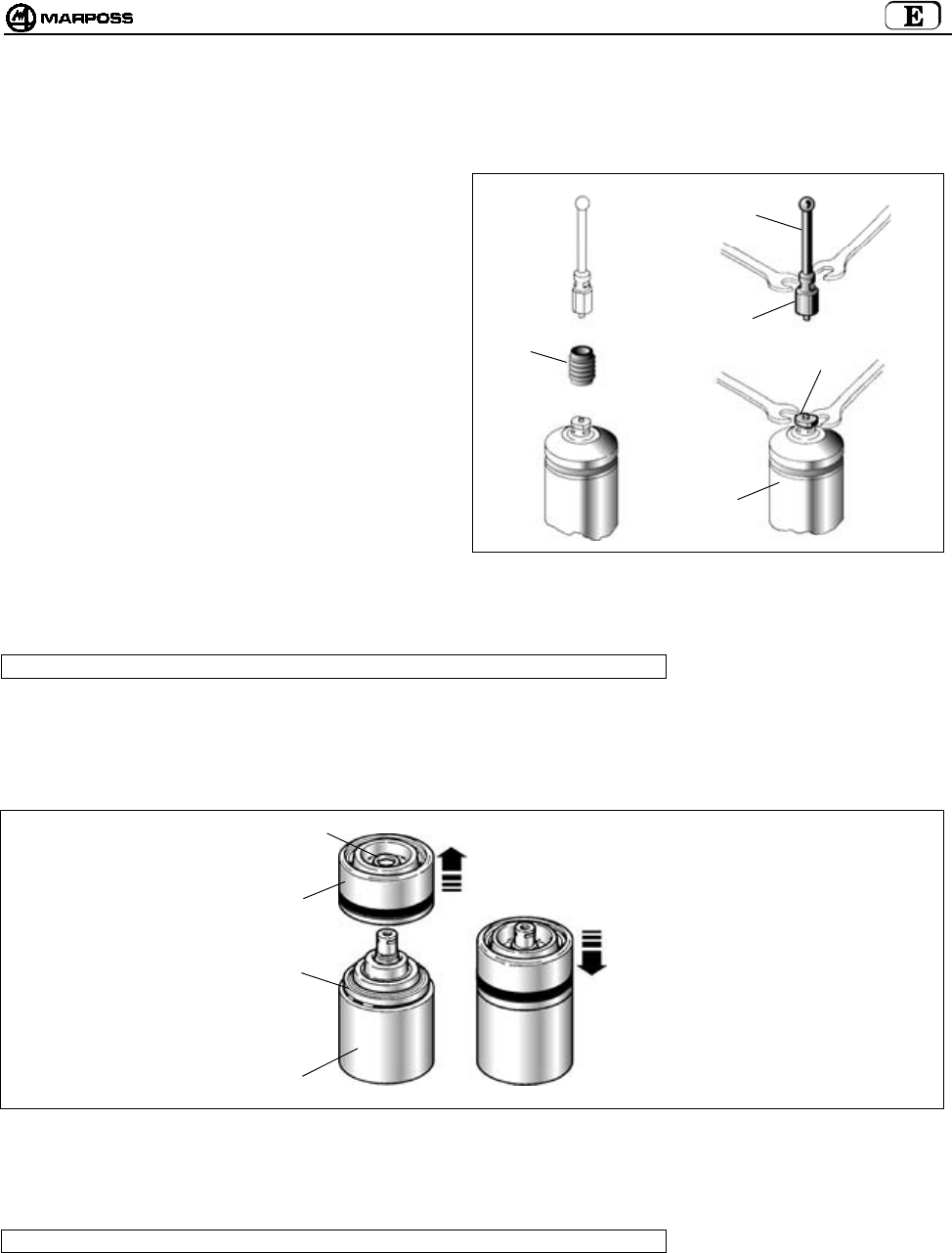
mida 221
15.2 Mantenimiento extraordinario
15.2.1 Reemplazo clavija de rotura/brazo
En caso de golpes accidentales en el brazo reemplazar la
clavija rota y/o el brazo como a continuación.
1. Soltar el retén (A) sacándolo de la clavija rota o
doblada.
2. Soltar el brazo (B) y la sonda (C) de la clavija rota (D).
3. Retirar el brazo dañado de la sonda (C).
Nota: Ejecutar estas operaciones sujetando el
portabrazo de la sonda con la llave
suministrada con el equipo.
4. Proceder con la desinstalación de la nueva clavija y del
brazo (véase "Instalación del brazo sonda").
Figura 15-2
15.2.2 Reemplazo junta externa
Note: este procedimiento es válido solo para sondas instaladas en transmisores Estándares
1- Retirar el brazo y la supuesta clavija de rotura.
2- Sacar del cuerpo sonda (A) la protección delantera (B) con junta (C).
3- Comprobar el estado del anillo de estanqueidad delantero (D) y si es necesario reemplazarlo.
4- Insertar la nueva protección delantera con junta hasta que se produzca el chasquido.
Figura 15-3
15.2.3 Reemplazo sonda/transmisor
Note: este procedimiento es válido solo para sondas instaladas en transmisores Estándares
1. Retirar el brazo y la supuesta clavija de rotura.
Véase "Instalación del brazo sonda".
2- Proceder con el reemplazo de la sonda como se indica en "Instalación/desinstalación sonda-transmisor".
D
B
C
A
A
D
B
C
D
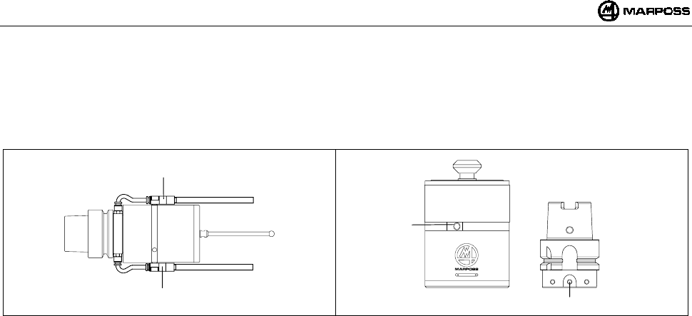
ESPAÑOL
E86N- Sistema touch con transmisión radio
222
16. ACCESORIOS
16.1 Grupo soporte aire de limpieza para Transmisor Compacto
El grupo soporte aire de limpieza (A) debe fijarse en los respectivos orificios (B) presentes en el transmisor y en el cono (Figura 16-2).
La presión de aire suministrada debe ser ≤6 bar (88.175psi).
Figura 16-1 Figura 16-2
A
A
B
B

mida 223
17. LISTA PIEZAS DE REPUESTO
CÓDIGO N° DESCRIPCIÓN NOTAS
1019108005 Clavija de rotura longitud 15 mm
1019108003 Retén brazo
2915335018 Kit de repuestos para T25/TL25/TT25 INCLUYE:
protección delantera con junta, O-ring delantero y
trasero, retén brazo
2915340010 Kit de repuestos para T36G INCLUYE:
protección delantera sonda con junta, O-ring y retén
brazo
2915345007 Kit de repuestos para T60G/TT60 INCLUYE:
protección delantera sonda con junta, O-ring y retén
brazo
2915335013 Protección delantera para T25/TL25/TT25
2915340006 Protección delantera para T36
2915345012 Protección delantera para T60
3415335200 Sonda T25G
3415335201 Sonda T25S
3424306040 Sonda TL25G
3424306041 Sonda TL25S
3415340200 Sonda T36G
3415340201 Sonda T36S
3415345030 Sonda T60G
3415345050 Sonda T60S
3424310000 Sonda TT25
3424310100 Sonda TT25H
3424451000 Sonda TT60
2019923021 Brida fijación transmisor para T25/TL25/TT25 Con O-ring
2019923022 Brida fijación transmisor para T36 Con O-ring
2019923023 Brida fijación transmisor para T60/TT60 Con O-ring
2915335023 Prolongación para T25/TL25/TT25 L=23,5 mm
2915335100 Prolongación para T25/TL25/TT25 L=50 mm
2915335110 Prolongación para T25/TL25/TT25 L=100 mm
2915335120 Prolongación para T25/TL25/TT25 L=150 mm
2915340125 Prolongación para T36 L=50 mm
2915340126 Prolongación para T36 L=100 mm
2915340127 Prolongación para T36 L=150 mm
2915345040 Prolongación para T60/TT60 L=50 mm
2915345050 Prolongación para T60/TT60 L=100 mm
2915345060 Prolongación para T60/TT60 L=150 mm
3019917110 Cono DIN 69871/A 40 con interruptor y brida de regulación
3019917120 Cono DIN 69871/A 45 con interruptor y brida de regulación
3019917130 Cono DIN 69871/A 50 con interruptor y brida de regulación
3019917140 Cono CAT 40 con interruptor y brida de regulación
3019917150 Cono CAT 45 con interruptor y brida de regulación
TRANSMISOR ESTÁNDAR E86N Y SONDAS
3019917160 Cono CAT 50 con interruptor y brida de regulación
1502027040 Junta para casquete
1502027050 Junta casquete (lado contactos)
1502018260 Tornillo especial para portapila
4162100005 Pila Alcalina 9V
4162100302 Pila Litio 9V
6180830500 Tapa portapila sin contactos
2015340100 Kit llaves INCLUYE:
llaves para el brazo y llaves Allen de
1,5 – 2 – 2,5 – 3 – 4 mm
1320131000 Llave especial para T25/TL25/TT25
1320367000 Llave especial para brida T25/TL25/T36/T60/TT25/TT60
2919917110 Brida de regulación para transmisor Estándar
6871982001 Transmisor E86N con activación radio
6871982101 Transmisor E86N con activación mecánica

ESPAÑOL
E86N- Sistema touch con transmisión radio
224

mida 225
CÓDIGO N° DESCRIPCIÓN NOTAS
1019108005 Clavija de rotura longitud 15 mm
1019108003 Retén brazo
2015340100 Kit llaves INCLUYE:
llaves para el brazo y llaves Allen de
1,5 – 2 – 2,5 – 3 – 4 mm
4400000219 Juntas OR 2081 PARKER 2-19 (para tapa pila)
4306400804 Tornillos TCCE UNI-5931-12K M4X8 (para tapa pila)
4162100004 Pila Alcalina 1,5V
6180980085 Grupo aire limpieza
TRANSMISOR COMPACTO E86N-P
6871983000 Transmisor E86N-P con activación radio
6871980000 Antena E86N
6180985017 Cable para conexión antena 15m
ANTENA Y
PROLONGACIONE
6180985027 Cable para conexión antena 30m
INTERFAZ
8304870000 Interfaz E86N
ACESSÓRIOS
6739696319 Alargue conexion – E86N CNC HEIDEN HAIN

ESPAÑOL
E86N- Sistema touch con transmisión radio
226

Printed in Italy