Marvell Semiconductor W8997-M1216 IEEE 802.11 2X2 MU-MIMO ac/a/b/g/n Wireless LAN + Bluetooth NGFF Module User Manual AW AH691A
Marvell Semiconductor, Inc. IEEE 802.11 2X2 MU-MIMO ac/a/b/g/n Wireless LAN + Bluetooth NGFF Module AW AH691A
Contents
- 1. User Manual rev 2.pdf
- 2. (W8997-M1216) UserMan
- 3. 04 User Manual_1
- 4. 04 User Manual_2
User Manual rev 2.pdf

Marvell Semiconductor, Inc.
- 1 -
IEEE 802.11 2X2 MU-MIMO ac/a/b/g/n Wireless
LAN + Bluetooth NGFF Module
W8997-M1216
(AW-CM276NF)
EVB User Manual
Version 0.3

Marvell Semiconductor, Inc.
- 2 -
1. Test environment requirement
OS
Linux OS(later than Ubuntu 14.04)
Interface
PCIE
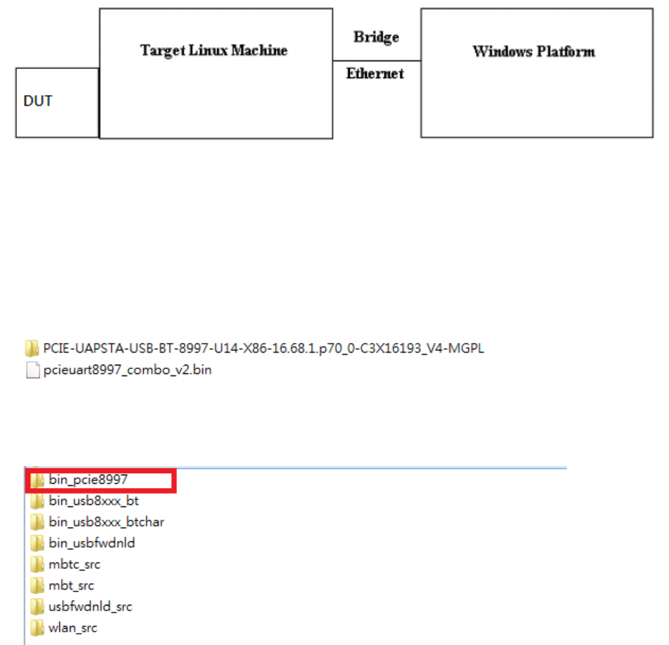
2. EVB connections
3. EVB set up with Linux PC
Please follow document “AW-CM276NF WLAN & Bluetooth MFG Tool Command
User Guide” and start the RF test.
Marvell Semiconductor, Inc.
- 3 -
4. Environment set up and Bridge Mode Tool
The “Manufacturing Bridge” refers to the application that allows a user to send commands between Target
platform and Windows XP platform. The environment enables the user to test performance of the
AW-CM276NF.
Manufacturing Bridge mode
4.1 Linux PC set up
(1) Driver Folder Contents
Download the latest driver package release from Azurewave FAE and unzip it. The driver folder should
look similar to the figure shown below. The release contains driver folder and FW image.
After opening above folder, you can see the folders as picture below. The working direction is
“bin_pcie8997”.
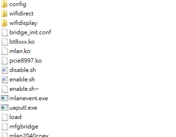
In this folder, it includes pre-built driver file and quick start script as below picture.
Marvell Semiconductor, Inc.
- 4 -
On the given Host Linux system, the following files have to be transferred & reside on the system.
(Transfer the files over via flash memory or tftp over the host.)
Place the firmware in /lib/firmware/mrvl/
Ex. pcieuart8997_combo_v2.bin (for PCIE/USB interface)
The user may need to compile the driver per your specific Linux OS and Kernel. This is due to that the driver
is dependent on the actual OS and kernel version. This next section will describe the steps needed to be
done before you can install the driver and run it.
Go to the subdirectory wlan_src
*Make sure to have kernel headers and kernel libs before executing the “make” commands below.
make clean
make build
Go up one folder to copy both *.ko files to your directory in where you have the other files in where you want to
run the insmod command.
Here is the sample list of files (as a minimum) at 1 location:
bridge_init.conf
mfgbridge
mlan.ko
pcie8897.ko
bt8xxx.ko
Marvell Semiconductor, Inc.
- 5 -
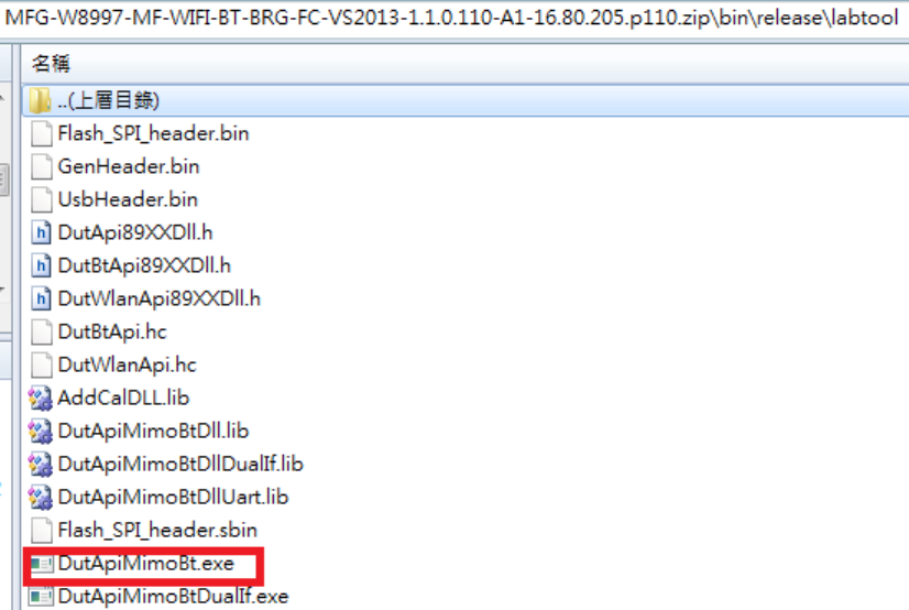
4.2 Windows PC set up
Within the internal folder is the labtool and other folders. For this document’s purpose, only the details of
the labtool folder will be discussed. The contents of the labtool folder are shown below.
The Labtool executable is labeled (DutApiMimoBt.exe)

Marvell Semiconductor, Inc.
- 6 -
5. Start driver installation and DUT testing
Now you can run the following commands to install the driver and firmware and start the Manufacturing bridge
application with the following commands.
On the working direction, use the following commands to put the 88W8997 in MFG mode after power on DUT.
./enable
Bring up the ethernet interface and specify an IP address to the Target platform. This address must match the
IP for the DUT in which the Host XP is expecting.
At this point, the target is ready to receive Labtool commands. On the Windows XP laptop where the Labtool
release was downloaded, go to the folder shown below:

Marvell Semiconductor, Inc.
- 7 -
Edit the “SetUp.ini” file as shown in the lines highlighted in RED below. The setup
DutIpAddress will be the IP address of your target.
Then you can double click “DutApiMimoBt.exe” to enter labtool as below picture.
5.1 Initial Command
As the information showed on your screen, please enter these commands below to start your test.
(Figure 9)
Command: 1 Wi-Fi testing
Command: 2 BT testing
Marvell Semiconductor, Inc.
- 8 -
5.2 Generate 802.11a/b/g/n/ac Packet commands
a. Tx on CH 6 at 10 dBm with a CCK-11Mbps data rate in 20 MHz BW mode on path A
25 // Stop Tx
10 1 1 // Set Path A Only
30 0 // Set to 2.4 GHz Band
112 0 // Set to 20 MHz BW
22 0 6 10 0 // Set to CH 6 at 10 dBm Output Power with CCK/BPSK Data Rate on Path A
25 1 4 // Tx at 11 Mbps
--------------------------------------------------------------------------------------------------------------------------------------
b. Tx on CH 6 at 10 dBm with a CCK-11Mbps data rate in 20 MHz BW mode on path B
25 // Stop Tx
10 2 2 // Set Path B Only
30 0 // Set to 2.4 GHz Band
112 0 // Set to 20 MHz BW
22 1 6 10 0 // Set to CH 6 at 10 dBm Output Power with CCK/BPSK Data Rate on Path B
25 1 4 // Tx at 11 Mbps
----------------------------------------------------------------------------------------------------------------------------------
c. Tx on CH 6 at 10 dBm with a OFDM-54Mbps data rate in 20 MHz BW mode on path B
25 // Stop Tx
10 2 2 // Set Path B Only
30 0 // Set to 2.4 GHz Band
112 0 // Set to 20 MHz BW
22 1 6 10 1 // Set to CH 6 at 10 dBm Output Power with OFDM(a mode or g mode) Data
//Rate on Path B
25 1 4 // Tx at 11 Mbps
----------------------------------------------------------------------------------------------------------------------------------
d. Tx on CH 36 at 8 dBm with a MCS7 Data rate in 20 MHz BW Mode on Path A
25 // Stop Tx

Marvell Semiconductor, Inc.
- 9 -
10 1 1 // Set Path A
30 1 // Set to 5 GHz Band
112 0 // Set to 20 MHz BW
22 0 36 8 2 // Set to CH 36 at 8 dBm Output Power with OFDM(n or ac mode)
// Data Rate on Path A
25 1 22 // Tx at MCS 7
-----------------------------------------------------------------------------------------------------------------------------------
e. Tx on CH 36-40 at 12 dBm with a MCS7 Data rate in 40 MHz BW Mode on Path A
25 // Stop Tx
10 1 1 // Set Path A
30 1 // Set to 5 GHz Band
112 1 // Set to 40 MHz BW
22 0 36 12 2 // Set to CH 36-40 at 12 dBm Output Power with OFDM(n or ac mode)
// Data Rate on path A
25 1 22 // Tx at MCS 7
-----------------------------------------------------------------------------------------------------------------------------------
f. Tx on CH 42(5210MHz) at 11 dBm with a MCS9 Data rate in 80 MHz BW Mode on Path A
25 // Stop Tx
10 1 1 // Set Path A
30 1 // Set to 5 GHz Band
112 4 // Set to 80 MHz BW
22 0 36 11 2 // Set to CH 42 at 11 dBm Output Power with OFDM(n or ac mode)
// Data Rate on path A
25 1 110 // Tx at MCS 9
Data rate set up
B mode & G mode:
1Mbps
5.5Mbps
11Mbps
6Mbps
9Mbps
12Mbps
18Mbps
24Mbps
1
3
4
6
7
8
9
10
36Mbps
48Mbps
54Mbps
11
12
13

Marvell Semiconductor, Inc.
- 10 -
N mode:
MCS0
MCS1
MCS2
MCS3
MCS4
MCS5
MCS6
MCS7
15
16
17
18
19
20
21
22
AC mode:
VHT Data Rates:
101 for VHT_SS1_MCS0
102 for VHT_SS1_MCS1
103 for VHT_SS1_MCS2
104 for VHT_SS1_MCS3
105 for VHT_SS1_MCS4
106 for VHT_SS1_MCS5
107 for VHT_SS1_MCS6
108 for VHT_SS1_MCS7
109 for VHT_SS1_MCS8
110 for VHT_SS1_MCS9
111 for VHT_SS2_MCS0
112 for VHT_SS2_MCS1
113 for VHT_SS2_MCS2
114 for VHT_SS2_MCS3
115 for VHT_SS2_MCS4
116 for VHT_SS2_MCS5
117 for VHT_SS2_MCS6
118 for VHT_SS2_MCS7
119 for VHT_SS2_MCS8
120 for VHT_SS2_MCS9
After you type above command, you can measure the 802.11b/g/n packet by your RF test instrument (exp:
Agilent 4010, IQview…).
5.3 Generate 802.11a/b/g/n/ac continuous symbol Commands
a. Cont. Tx on CH 36 at 8 dBm with a MCS7 Data rate in 20 MHz BW Mode on Path A
17 // Stop Cont. Tx
25 // Stop Tx
Marvell Semiconductor, Inc.
- 11 -
10 1 1 // Set Path A
30 1 // Set to 5 GHz Band
112 0 // Set to 20 MHz BW
22 0 36 8 2 // Set to CH 36 at 8 dBm Output Power with OFDM Data Rate on Path A
25 1 22 // Tx at MCS 7
25 // Stop Tx
17 1 22 // Cont. Tx at MCS7
17 // Stop Cont. Tx
5.4 Test RX sensitivity Commands
a. Rx on CH 157 in 20 MHz BW Mode on both Path A
25 // Stop Tx
10 1 1 // Set to Path A
30 1 // Set to 5 GHz Band
112 0 // Set to 20 MHz BW
12 100 // Set to CH 100
31 // Clear all the received packets
32 // Get Rx Packet Count and then clear the Rx packet counter
5.5 Others Commands
(1) Command 45 Check the MAC
(2) Command 99 Quit the test mode/ Quit the MFG tool
5.6 BT test mode Commands
This is how we test our BT: let BT enter test mode, then connect to tester for testing.
(1) Command 45Check BT MAC.
(2) Command 78 1BT enter test mode.
After you type above command, you can measure BT signal both TX/RX and the other BT test items by your
BT instrument.
Marvell Semiconductor, Inc.
- 12 -
6. Installation and setting on customer’s platform
AW-CM276NF is a M.2 type 1216 solder down module, which needs SMT process to assembly on
customer’s platform. The software setup steps is same as MFG one(step 4.1). Customer only needs to
replace MFG FW by normal FW.
Than the module could be brought up and work properly.
Marvell Semiconductor, Inc.
- 13 -
Federal Communication Commission Interference Statement
This device complies with Part 15 of the FCC Rules. Operation is subject to the following two
conditions: (1) This device may not cause harmful interference, and (2) this device must accept any
interference received, including interference that may cause undesired operation.
This equipment has been tested and found to comply with the limits for a Class B digital device,
pursuant to Part 15 of the FCC Rules. These limits are designed to provide reasonable protection
against harmful interference in a residential installation. This equipment generates, uses and can
radiate radio frequency energy and, if not installed and used in accordance with the instructions, may
cause harmful interference to radio communications. However, there is no guarantee that
interference will not occur in a particular installation. If this equipment does cause harmful
interference to radio or television reception, which can be determined by turning the equipment off
and on, the user is encouraged to try to correct the interference by one of the following measures:
- Reorient or relocate the receiving antenna.
- Increase the separation between the equipment and receiver.
- Connect the equipment into an outlet on a circuit different from that
to which the receiver is connected.
- Consult the dealer or an experienced radio/TV technician for help.
FCC Caution: Any changes or modifications not expressly approved by the party responsible for
compliance could void the user's authority to operate this equipment.
This transmitter must not be co-located or operating in conjunction with any other antenna or
transmitter.
Radiation Exposure Statement:
This equipment complies with FCC radiation exposure limits set forth for an uncontrolled
environment. This equipment should be installed and operated with minimum distance 20cm between
the radiator & your body.

Marvell Semiconductor, Inc.
- 14 -
This device is intended only for OEM integrators under the following conditions:
1) The antenna must be installed such that 20 cm is maintained between the antenna and users, and
2) The transmitter module may not be co-located with any other transmitter or antenna.
As long as 2 conditions above are met, further transmitter test will not be required. However, the OEM
integrator is still responsible for testing their end-product for any additional compliance requirements
required with this module installed
IMPORTANT NOTE: In the event that these conditions can not be met (for example certain laptop
configurations or co-location with another transmitter), then the FCC authorization is no longer
considered valid and the FCC ID can not be used on the final product. In these circumstances, the
OEM integrator will be responsible for re-evaluating the end product (including the transmitter) and
obtaining a separate FCC authorization.
End Product Labeling
This transmitter module is authorized only for use in device where the antenna may be installed such
that 20 cm may be maintained between the antenna and users. The final end product must be labeled
in a visible area with the following: “Contains FCC ID: UAY-W8997-M1216”. The grantee's FCC ID
can be used only when all FCC compliance requirements are met.
Manual Information To the End User
The OEM integrator has to be aware not to provide information to the end user regarding how to
install or remove this RF module in the user’s manual of the end product which integrates this module.
The end user manual shall include all required regulatory information/warning as show in this manual.
Marvell Semiconductor, Inc.
- 15 -
Industry Canada statement:
This device complies with ISED’s licence-exempt RSSs. Operation is subject to the following two conditions:
(1) This device may not cause harmful interference, and (2) this device must accept any interference received,
including interference that may cause undesired operation.
Le présent appareil est conforme aux CNR d’ ISED applicables aux appareils radio exempts de licence.
L’exploitation est autorisée aux deux conditions suivantes : (1) le dispositif ne doit pas produire de brouillage
préjudiciable, et (2) ce dispositif doit accepter tout brouillage reçu, y compris un brouillage susceptible de
provoquer un fonctionnement indésirable.
Radiation Exposure Statement:
This equipment complies with ISED radiation exposure limits set forth for an uncontrolled environment. This
equipment should be installed and operated with minimum distance 25cm between the radiator & your body.
Déclaration d'exposition aux radiations:
Cet équipement est conforme aux limites d'exposition aux rayonnements ISED établies pour un
environnement non contrôlé. Cet équipement doit être installé et utilisé avec un minimum de 25 cm de
distance entre la source de rayonnement et votre corps.
This device is intended only for OEM integrators under the following conditions: (For module device use)
1) The antenna must be installed such that 25 cm is maintained between the antenna and users, and
2) The transmitter module may not be co-located with any other transmitter or antenna.
As long as 2 conditions above are met, further transmitter test will not be required. However, the OEM
integrator is still responsible for testing their end-product for any additional compliance requirements required
with this module installed.
Cet appareil est conçu uniquement pour les intégrateurs OEM dans les conditions suivantes: (Pour utilisation de
dispositif module)
1) L'antenne doit être installée de telle sorte qu'une distance de 25 cm est respectée entre l'antenne et les
utilisateurs, et
2) Le module émetteur peut ne pas être coïmplanté avec un autre émetteur ou antenne.
Tant que les 2 conditions ci-dessus sont remplies, des essais supplémentaires sur l'émetteur ne seront pas
nécessaires. Toutefois, l'intégrateur OEM est toujours responsable des essais sur son produit final pour toutes
exigences de conformité supplémentaires requis pour ce module installé.
Marvell Semiconductor, Inc.
- 16 -
IMPORTANT NOTE:
In the event that these conditions can not be met (for example certain laptop configurations or co-location
with another transmitter), then the Canada authorization is no longer considered valid and the IC ID can not
be used on the final product. In these circumstances, the OEM integrator will be responsible for re-evaluating
the end product (including the transmitter) and obtaining a separate Canada authorization.
NOTE IMPORTANTE:
Dans le cas où ces conditions ne peuvent être satisfaites (par exemple pour certaines configurations
d'ordinateur portable ou de certaines co-localisation avec un autre émetteur), l'autorisation du Canada n'est
plus considéré comme valide et l'ID IC ne peut pas être utilisé sur le produit final. Dans ces circonstances,
l'intégrateur OEM sera chargé de réévaluer le produit final (y compris l'émetteur) et l'obtention d'une
autorisation distincte au Canada.
End Product Labeling
This transmitter module is authorized only for use in device where the antenna may be installed such that 25
cm may be maintained between the antenna and users. The final end product must be labeled in a visible area
with the following: “Contains IC: 6549A-W8997M1216”.
Plaque signalétique du produit final
Ce module émetteur est autorisé uniquement pour une utilisation dans un dispositif où l'antenne peut être
installée de telle sorte qu'une distance de 25cm peut être maintenue entre l'antenne et les utilisateurs. Le
produit final doit être étiqueté dans un endroit visible avec l'inscription suivante: "Contient des IC:
6549A-W8997M1216".
Manual Information To the End User
The OEM integrator has to be aware not to provide information to the end user regarding how to install or
remove this RF module in the user’s manual of the end product which integrates this module.
The end user manual shall include all required regulatory information/warning as show in this manual.
Manuel d'information à l'utilisateur final
L'intégrateur OEM doit être conscient de ne pas fournir des informations à l'utilisateur final quant à la façon
d'installer ou de supprimer ce module RF dans le manuel de l'utilisateur du produit final qui intègre ce module.
Le manuel de l'utilisateur final doit inclure toutes les informations réglementaires requises et avertissements
comme indiqué dans ce manuel.
Marvell Semiconductor, Inc.
- 17 -
Caution :
(i) the device for operation in the band 5150-5250 MHz is only for indoor use to reduce the potential for
harmful interference to co-channel mobile satellite systems;
(ii) the maximum antenna gain permitted for devices in the bands 5250-5350 MHz and 5470-5725 MHz shall
be such that the equipment still complies with the e.i.r.p. limit;
(iii) the maximum antenna gain permitted for devices in the band 5725-5850 MHz shall be such that the
equipment still complies with the e.i.r.p. limits specified for point-to-point and non-point-to-point operation as
appropriate; and
(iv) the worst-case tilt angle(s) necessary to remain compliant with the e.i.r.p. elevation mask requirement set forth
in Section 6.2.2(3) shall be clearly indicated.
(v) Users should also be advised that high-power radars are allocated as primary users (i.e. priority users) of
the bands 5250-5350 MHz and 5650-5850 MHz and that these radars could cause interference and/or damage
to LE-LAN devices.
Avertissement:
Le guide d’utilisation des dispositifs pour réseaux locaux doit inclure des instructions précises sur les
restrictions susmentionnées, notamment :
(i) les dispositifs fonctionnant dans la bande 5150-5250 MHz sont réservés uniquement pour une utilisation à
l’intérieur afin de réduire les risques de brouillage préjudiciable aux systèmes de satellites mobiles utilisant
les mêmes canaux;
(ii) le gain maximal d'antenne permis pour les dispositifs utilisant les bandes de 5250 à 5 350 MHz et de 5470 à
5725 MHz doit être conforme à la limite de la p.i.r.e;
(iii) le gain maximal d'antenne permis (pour les dispositifs utilisant la bande de 5 725 à 5 850 MHz) doit être
conforme à la limite de la p.i.r.e. spécifiée pour l'exploitation point à point et l’exploitation non point à point, selon
le cas;
(iv) les pires angles d’inclinaison nécessaires pour rester conforme à l’exigence de la p.i.r.e. applicable au masque
d’élévation, et énoncée à la section 6.2.2 3), doivent être clairement indiqués.

Marvell Semiconductor, Inc.
- 18 -
(v) De plus, les utilisateurs devraient aussi être avisés que les utilisateurs de radars de haute puissance sont
désignés utilisateurs principaux (c.-à-d., qu’ils ont la priorité) pour les bandes 5250-5350 MHz et 5650-5850
MHz et que ces radars pourraient causer du brouillage et/ou des dommages aux dispositifs LAN-EL.
低功率電波輻射性電機管理辦法
第十二條 經型式認證合格之低功率射頻電機,非經許可,公司、商號或使用者均不得
擅自變更頻率、加大功率或變更原設計之特性及功能。
第十四條 低功率射頻電機之使用不得影響飛航安全及干擾合法通信;經發現有干擾現
象時,應立即停用,並改善至無干擾時方得繼續使用。
前項合法通信,指依電信法規定作業之無線電通信。
低功率射頻電機須忍受合法通信或工業、科學及醫療用電波輻射性電機設備之
干擾。
在5.25-5.35 秭赫頻帶內操作之無線資訊傳輸設備,限於室內使用。
1. 本模組於取得認證後將依規定於模組本體標示審驗合格標籤。
2. 系統廠商應於平台上標示「本產品內含射頻模組: XXXyyyLPDzzzz-x」字樣