Masimo RAD7A RAD7A User Manual Radical 7
Masimo Corporation RAD7A Radical 7
UserManual.wiki
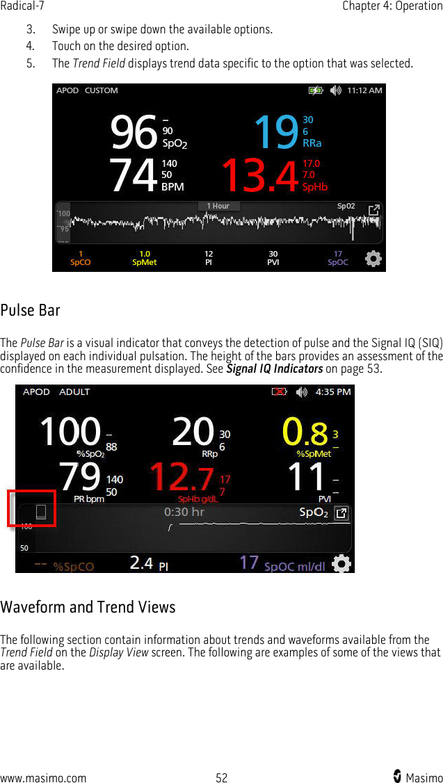
>
Masimo
>
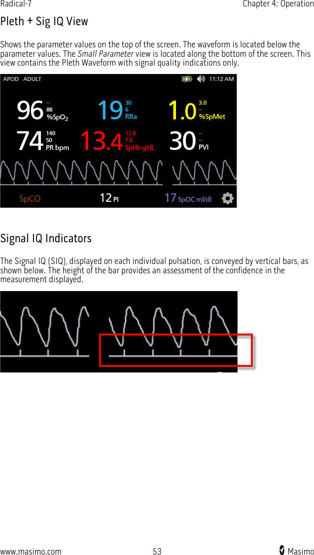
RAD7A User Manual
User Manual
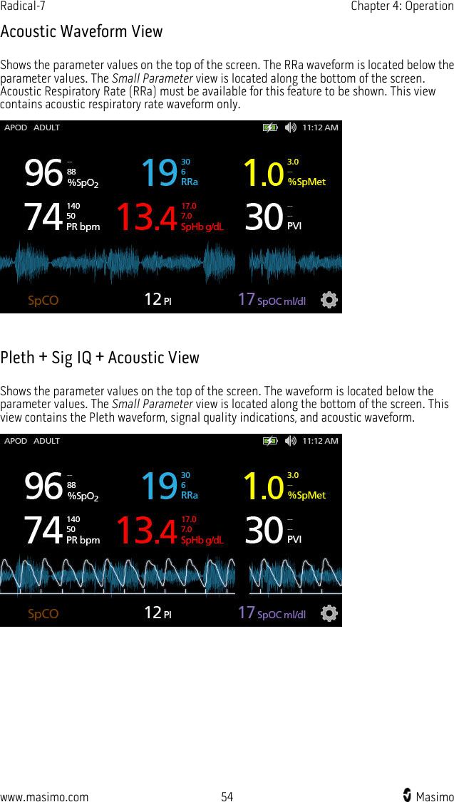
Navigation menu
Upload a User Manual
Namespaces
Wiki Guide
HTML
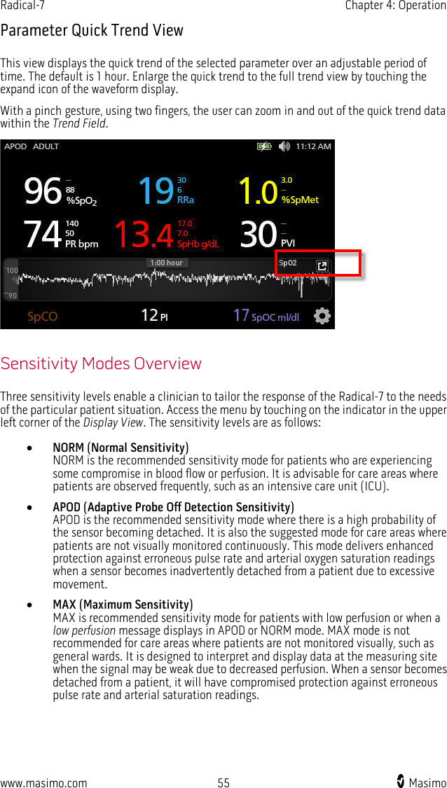
PDF
Info
Views
User Manual
Discussion / Help
Navigation
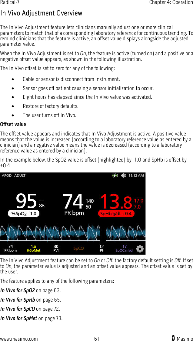
![www.masimo.com 9 Masimo Product Description, Indications for Use, Contraindications, and Features The following chapter contains the Radical-7 product description, key features and benefits, indications for use, contraindications, and safety information, including cautions, warnings, and notes. Product Description The Radical-7 is a noninvasive monitor that measures arterial oxygen saturation (SpO2), pulse rate (PR), and perfusion index (PI), along with optional measurements of hemoglobin (SpHb), carboxyhemoglobin (SpCO), total oxygen content (SpOC), methemoglobin (SpMet), Pleth Variability Index (PVI), Acoustic Respiration Rate (RRa), and Pleth Respiration Rate (RRp). The Radical-7 can be used as either a Handheld or a Standalone monitor. The Radical-7 features a touchscreen Liquid Crystal Display (LCD) that continuously displays numeric values for all parameters. The Radical-7 provides graphical displays for plethysmographic waveform, respiratory waveform, Signal Identification and Quality Indicator (Signal IQ). The Radical-7 can also be used to interface with a multi-parameter patient monitor to send Masimo SET pulse oximetry information to that monitor for display. The Radical-7 has an embedded 802.11 wireless radio that can be used for connectivity. Key Features The following features are available for the Radical-7. Some features are optional: • Masimo SET is clinically proven to satisfy all sensitivity and specificity requirements for pulse oximeter technology. • Rainbow technology uses 7+ wavelengths of light to continuously and noninvasively measure carboxyhemoglobin (SpCO), methemoglobin (SpMet), and total hemoglobin (SpHb), as well as providing a more reliable probe-off detection. • Total oxygen content (SpOC) provides a calculated measurement of the amount of oxygen in arterial blood, which may provide useful information about oxygen both dissolved in plasma and combined with hemoglobin. • Perfusion Index (PI) with trending capability indicates arterial pulse signal strength and may be used as a diagnostic tool during low perfusion. • Pleth Variability Index (PVI) may show changes that reflect physiologic factors such as vascular tone, circulating blood volume, and intrathoracic pressure excursions. [The utility of PVI is unknown at this time and requires further clinical studies. Technical factors that may affect PVI include probe malposition and patient motion.] • Respiration rate can be determined by the acoustic (RRa) or plethysmographic waveform (RRp).](https://usermanual.wiki/Masimo/RAD7A/User-Guide-2552569-Page-11.png)
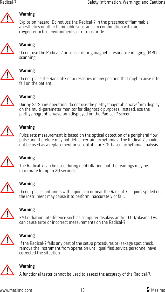
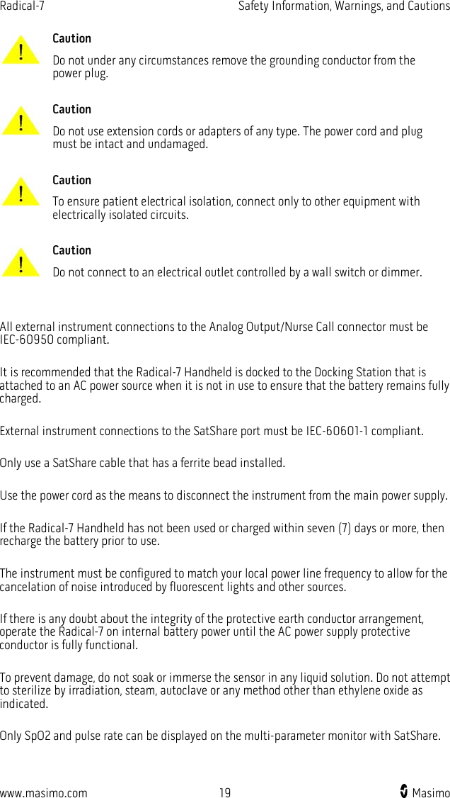
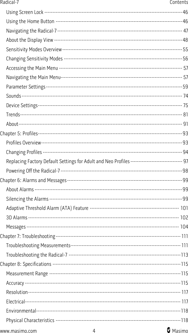
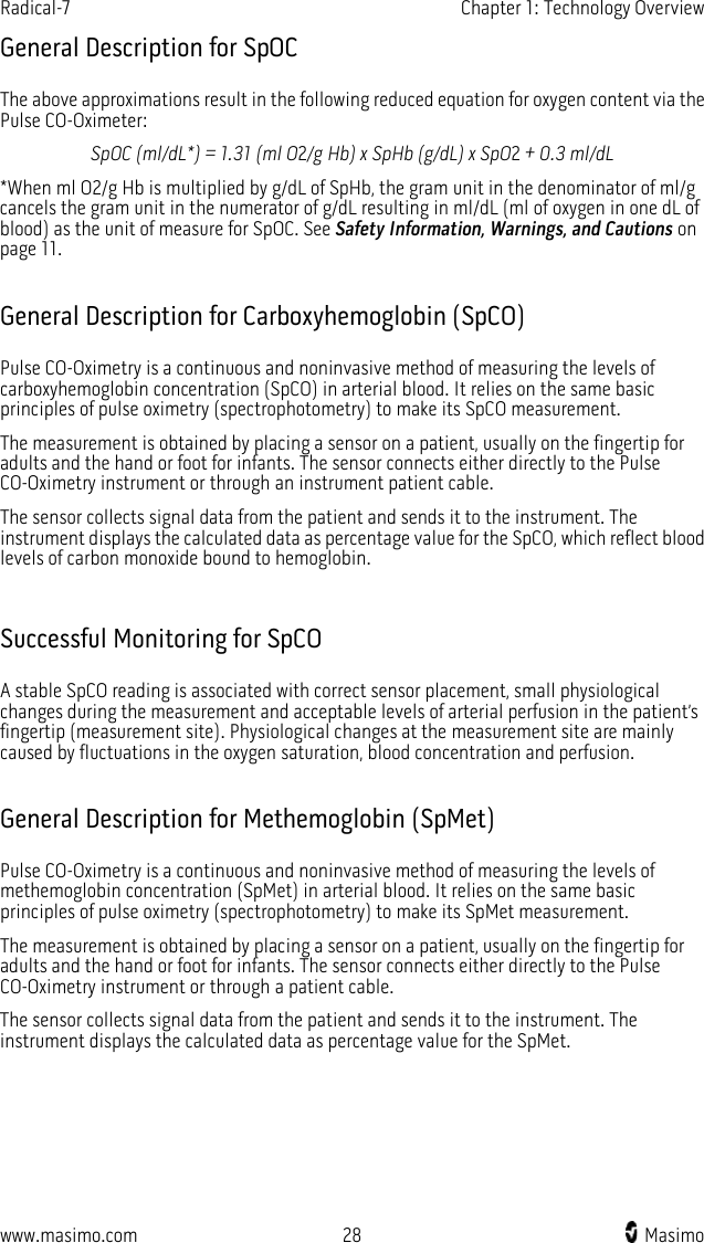
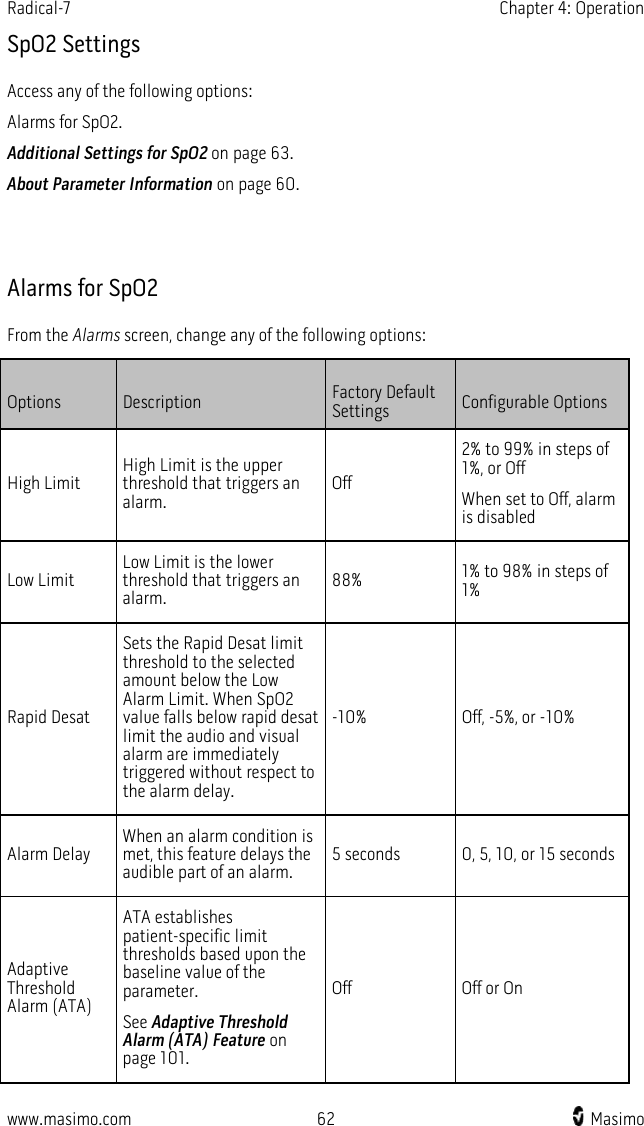
![Radical-7 Chapter 1: Technology Overview www.masimo.com 26 Masimo The Radical-7 uses a multi-wavelength sensor to distinguish between oxygenated blood, deoxygenated blood, blood with carbon monoxide, oxidized blood and blood plasma. The Radical-7 utilizes a sensor with various light-emitting diodes (LEDs) that pass light through the site to a diode (detector). Signal data is obtained by passing various visible and infrared lights (LEDs, 500 to 1400nm) through a capillary bed (for example, a fingertip, a hand, a foot) and measuring changes in light absorption during the blood pulsatile cycle. This information may be useful to clinicians. The maximum radiant power of the strongest light is rated at ≤ 25 mW. The detector receives the light, converts it into an electronic signal and sends it to the Radical-7 for calculation. 1. Light Emitting Diodes (LEDs) (7 + wavelengths) 2. Detector Once the Radical-7 receives the signal from the sensor, it utilizes proprietary algorithms to calculate the patient’s functional oxygen saturation (SpO2 [%]), blood levels of carboxyhemoglobin (SpCO [%]), methemoglobin (SpMet [%]), total hemoglobin concentration (SpHb [g/dL]) and pulse rate (PR). The SpCO, SpMet and SpHb measurements rely on a multi-wavelength calibration equation to quantify the percentage of carbon monoxide and methemoglobin and the concentration of total hemoglobin in arterial blood. In an ambient temperature of 35º C the maximum skin surface temperature has been measured at less than 106º F (41º C), verified by Masimo sensor skin temperature test procedure. Pulse CO-Oximetry vs. Drawn Whole Blood Measurements When SpO2, SpCO, SpMet, and SpHb measurements obtained from the Radical-7 (noninvasive) are compared to drawn whole blood (invasive) measurements by blood gas and/or laboratory CO-Oximetry methods, caution should be taken when evaluating and interpreting the results. The blood gas and/or laboratory CO-Oximetry measurements may differ from the SpO2, SpCO, SpMet, SpHb, and SpOC measurements of the Radical-7. Any comparisons should be simultaneous, meaning the measurement on the device should be noted at the exact time that blood is drawn. In the case of SpO2, different results are usually obtained from the arterial blood gas sample if the calculated measurement is not appropriately corrected for the effects of variables that shift the relationship between the partial pressure of oxygen (PO2) and saturation, such as: pH,temperature, the partial pressure of carbon dioxide (PCO2), 2,3-DPG, and fetal hemoglobin. In the case of SpCO, different results are also expected if concentration of methemoglobin in the blood gas sample is abnormal (greater than 2% for methemoglobin concentration). High levels of bilirubin may cause erroneous SpO2, SpMet, SpCO, and SpHb readings. As blood samples are usually taken over a period of 20 seconds (the time it takes to draw the](https://usermanual.wiki/Masimo/RAD7A/User-Guide-2552569-Page-28.png)
![Radical-7 Chapter 1: Technology Overview www.masimo.com 27 Masimo blood) a meaningful comparison can only be achieved if the oxygen saturation, carboxyhemoglobin, and methemoglobin concentration of the patient are stable and not changing over the period of time that the blood gas sample is taken. Subsequently, blood gas and laboratory CO-Oximetry measurements of SpO2, SpCO, SpMet, SpHb, and SpOC may vary with the rapid administration of fluids and in procedures such as dialysis. Additionally, drawn whole blood testing can be affected by sample handling methods and time elapsed between blood draw and sample testing. Measurements with Low Signal IQ should not be compared to laboratory measurements. General Description for Total Hemoglobin (SpHb) Pulse CO-Oximetry is a continuous and noninvasive method of measuring the levels of total hemoglobin (SpHb) in arterial blood. It relies on the same principles of pulse oximetry to make its SpHb measurement. The measurement is taken by a sensor capable of measuring SpHb, usually on the fingertip for adult and pediatric patients. The sensor connects directly to the Pulse CO-Oximeter or with a patient cable. The sensor collects signal data from the patient and sends it to the instrument. The instrument displays the calculated data as measurement of total hemoglobin concentration. Successful Monitoring for SpHb A stable SpHb reading is associated with correct sensor placement, small physiological changes during the measurement and acceptable levels of arterial perfusion at the measurement site. Physiological changes at the measurement site are mainly caused by fluctuations in the oxygen saturation, blood concentration and perfusion. See Safety Information, Warnings, and Cautions on page 11 and Troubleshooting Measurements on page 111. General Description for Total Arterial Oxygen Content (CaO2) Oxygen (O2) is carried in the blood in two forms, either dissolved in plasma or combined with hemoglobin. The amount of oxygen in the arterial blood is termed the oxygen content (CaO2) and is measured in units of ml O2/dL blood. One gram of hemoglobin (Hb) can carry 1.34 ml of oxygen, whereas 100 ml of blood plasma may carry approximately 0.3 ml of oxygen*. The oxygen content is determined mathematically as: CaO2 = 1.34 (ml O2/g Hb) x Hb (g/dL) x HbO2 + PaO2 (mm Hg) x (0.3 ml O2/100 mm Hg/dL) Where HbO2 is the fractional arterial oxygen saturation and PaO2 is the partial pressure of arterial oxygen. For typical PaO2 values, the second part of the above equation (PaO2 [mm Hg] x [0.3 ml O2/ 100 mm Hg/dL]) is approximately 0.3 ml/dL. Furthermore, for typical carboxyhemoglobin and methemoglobin levels, the functional saturation (SpO2) as measured by a pulse oximeter is given by: SpO2 = 1.02 x HbO2 *Martin, Laurence. All You Really Need to Know to Interpret Arterial Blood Gases, Second Edition. New York: Lippincott Williams & Wilkins, 1999.](https://usermanual.wiki/Masimo/RAD7A/User-Guide-2552569-Page-29.png)
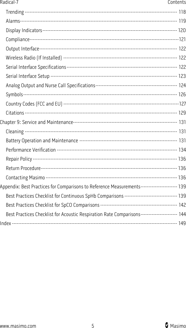
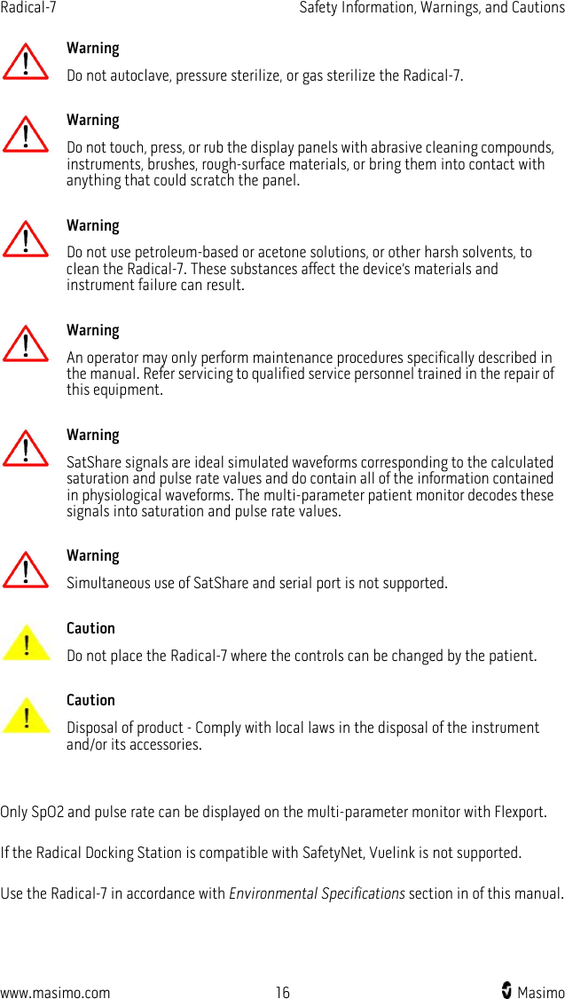
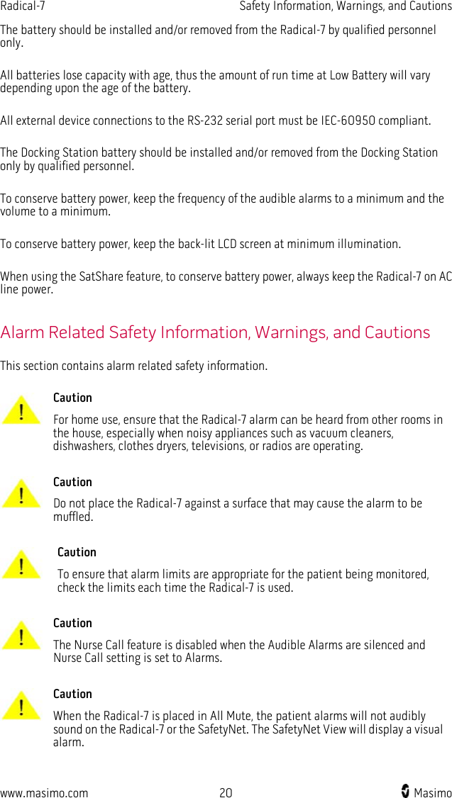
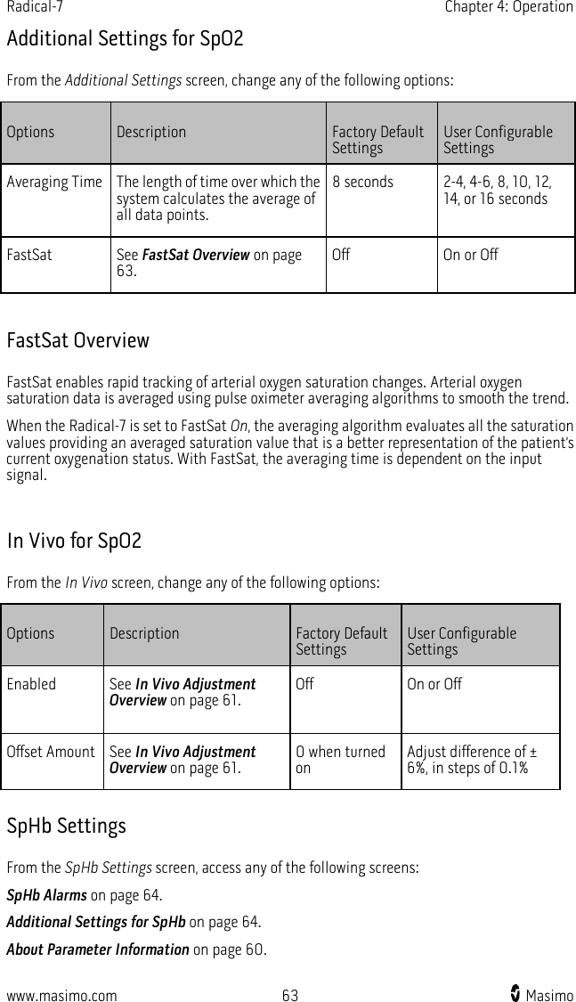
![Radical-7 Chapter 1: Technology Overview www.masimo.com 29 Masimo Successful Monitoring for SpMet A stable SpMet reading is associated with correct sensor placement, small physiological changes during the measurement and acceptable levels of arterial perfusion in the patient’s fingertip (measurement site). Physiological changes at the measurement site are mainly caused by fluctuations in the oxygen saturation, blood concentration and perfusion. See Safety Information, Warnings, and Cautions on page 11. SpCO, SpMet, and SpHb Measurements During Patient Motion The Radical-7 displays measurements of SpCO, SpMet, and SpHb during patient motion. However, because of the changes in the physiological parameters such as blood volume, arterial-venous coupling, etc. that occur during patient motion, the accuracy of such measurements may not be reliable during excessive motion. In this case, the measurement value for SpCO, SpMet, or SpHb displays as dashes (---) and a message (Low SpCO SIQ, Low SpMet SIQ, or Low SpHb SIQ) displays to alert the clinician that the instrument does not have confidence in the value due to poor signal quality caused by excessive motion or other signal interference. rainbow Acoustic Monitoring (RAM) Technology rainbow Acoustic Monitoring (RAM) continuously measures a patient’s respiration rate based on airflow sounds generated in the upper airway. The Acoustic Sensor translates airflow sounds generated in the upper airway to an electrical signal that can be processed to produce a respiration rate, measured as breaths per minute. Respiratory sounds include sounds related to respiration such as breath sounds (during inspiration and expiration), adventitious sounds, cough sounds, snoring sounds, sneezing sounds, and sounds from the respiratory muscles [1]. These respiratory sounds often have different characteristics depending on the location of recording [2] and they originate in the large airways where air velocity and air turbulence induce vibration in the airway wall. These vibrations are transmitted, for example, through the lung tissue, thoracic wall and trachea to the surface where they may be heard with the aid of a stethoscope, a microphone or more sophisticated devices. rainbow Acoustic Monitoring Architecture The following figure illustrates how a respiratory sound produced by a patient can be turned into a numerical measurement that corresponds to a respiratory parameter. Patient Sensor Acquisition System Respiratory airflow to sound Sound to electrical signal Electrical signal to digital signal](https://usermanual.wiki/Masimo/RAD7A/User-Guide-2552569-Page-31.png)
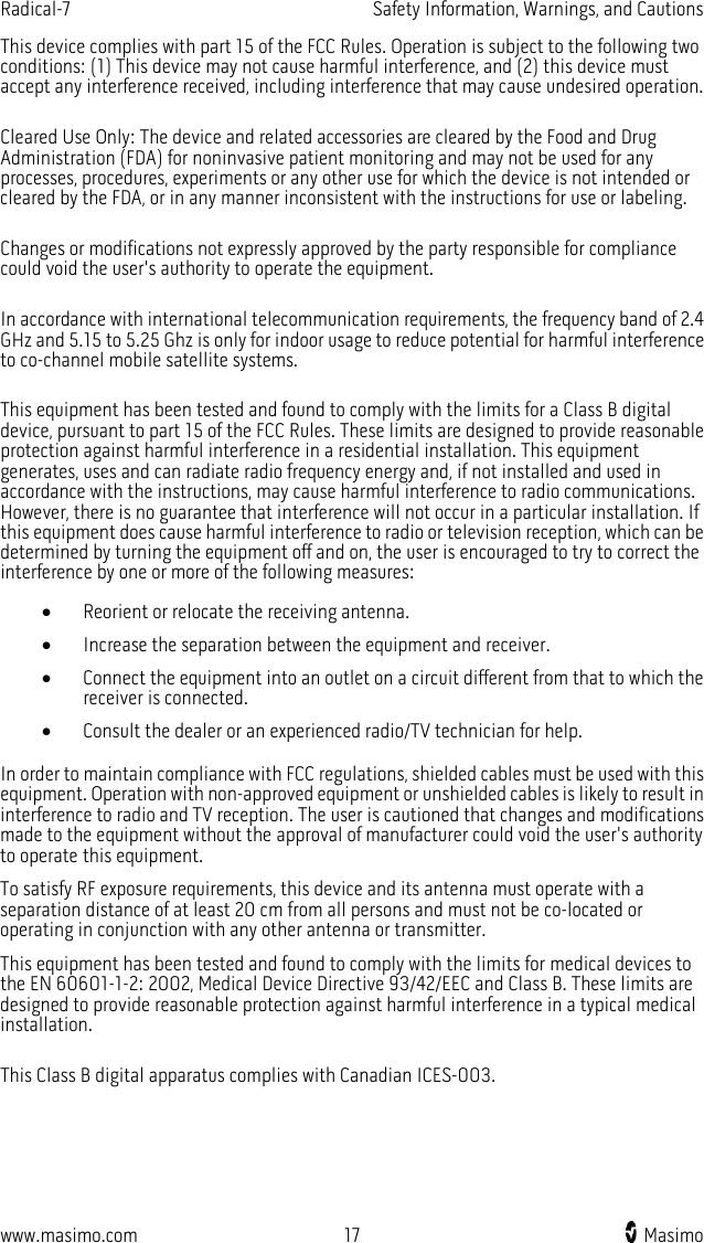
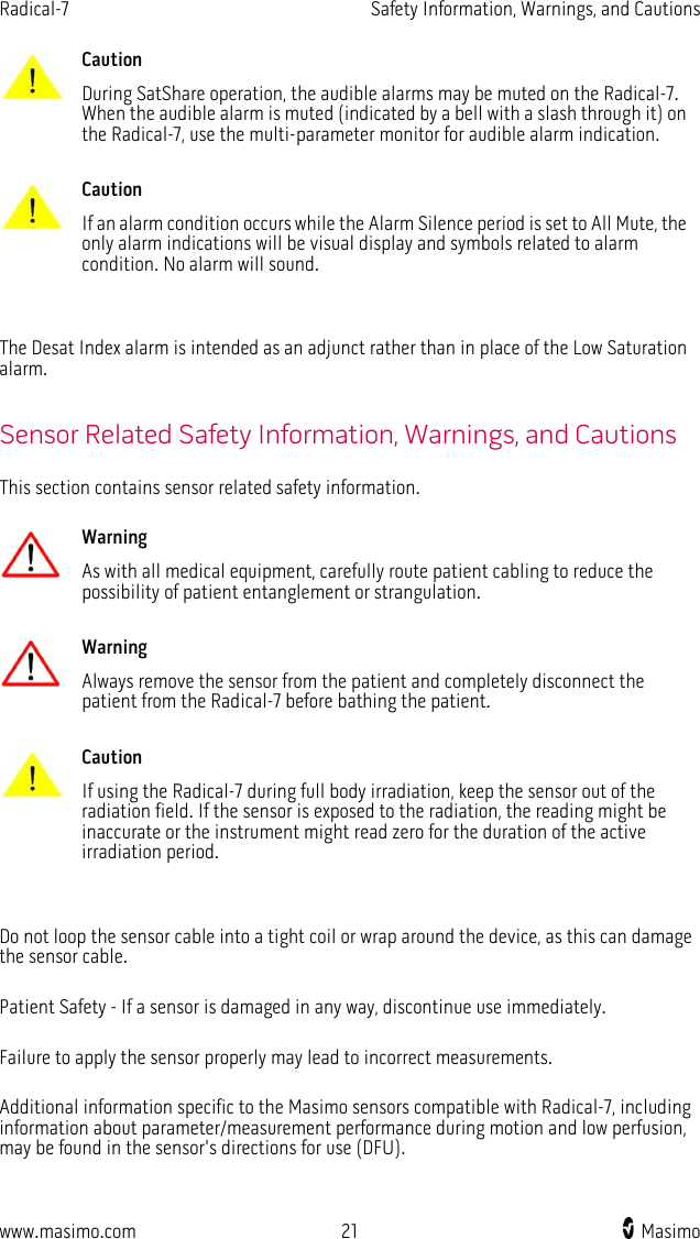
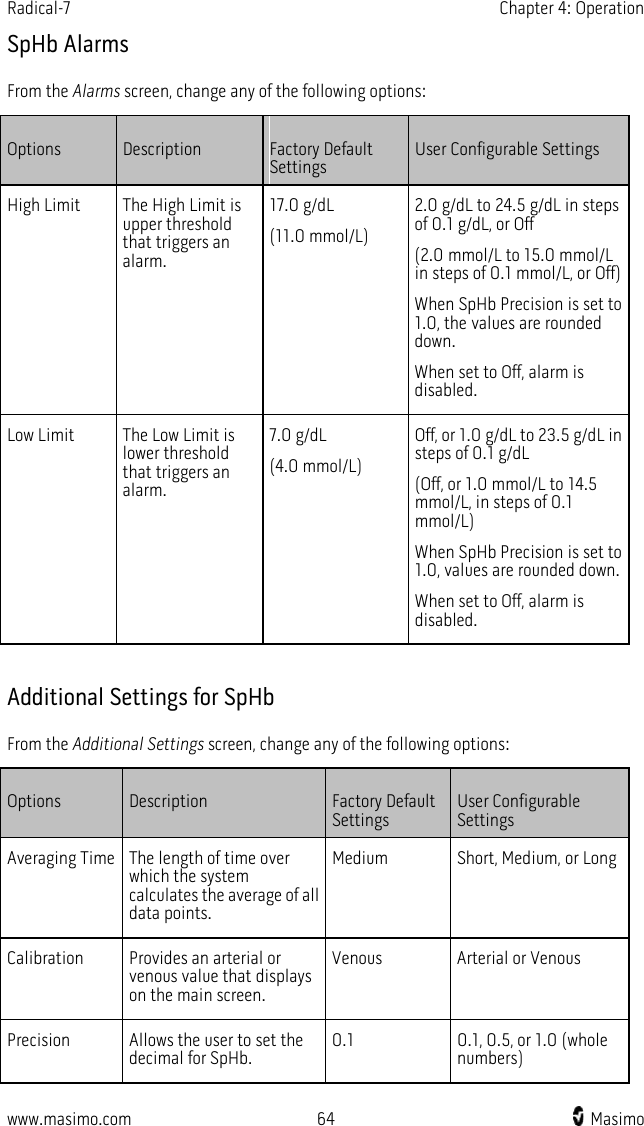
![Radical-7 Chapter 1: Technology Overview www.masimo.com 30 Masimo Signal Processing Envelope Detection RRa Estimation Digital signal to respiratory measurement Patient The generation of respiratory sounds is primarily related to turbulent respiratory airflow in upper airways. Sound pressure waves within the airway gas and airway wall motion contribute to the vibrations that reach the body surface and are recorded as respiratory sounds. Although the spectral shape of respiratory sounds varies widely from person to person, it is often reproducible within the same person, likely reflecting the strong influence of individual airway anatomy [2-6]. Sensor The sensor captures respiratory sounds (and other biological sounds) much like a microphone does. When subjected to a mechanical strain, (e.g., surface vibrations generated during breathing), the sensor becomes electrically polarized. The degree of polarization is proportional to the applied strain. The output of the sensor is an electric signal that includes a sound signal that is modulated by inspiratory and expiratory phases of the respiratory cycle. Acquisition System The acquisition system converts the electric signal provided by the sensor into a digital signal. This format allows the signal to be processed by a computing device.](https://usermanual.wiki/Masimo/RAD7A/User-Guide-2552569-Page-32.png)
![Radical-7 Chapter 1: Technology Overview www.masimo.com 31 Masimo Signal Processing The digital signal produced by the acquisition system is converted into a measurement that corresponds to the respiratory parameter of interest. As shown in the previous figure, this can be performed by, for example, determining the digital signal envelope or outline which in turn may be utilized to determine the respiratory rate. In this way, a real-time, continuous breath rate parameter can be obtained and displayed on a monitor which, in many cases, may be real-time and continuous. The respiratory cycle envelope signal processing principle is similar to methods that sample airway gasses and subsequently determine a respiratory rate. [1] A.R.A. Sovijärvi, F. Dalmasso, J. Vanderschool, L.P. Malmberg, G. Righini, S.A.T. Stoneman. Definition of terms for applications of respiratory sounds. Eur Respir Rev 2000; 10:77, 597-610. [2] Z. Moussavi. Fundamentals of respiratory sounds analysis. Synthesis lectures on biomedical engineering #8. Morgan & Claypool Publishers, 2006. [3] Olsen, et al. Mechanisms of lung sound generation. Semin Respir Med 1985; 6: 171-179. [4] Pastercamp H, Kraman SS, Wodicka GR. Respiratory sounds – Advances beyond the stethoscope. Am J Respir Crit Care Med 1977; 156: 974-987. [5] Gavriely N, Cugell DW. Airflow effects on amplitude and spectral content of normal breath sounds. J Appl Physiol 1996; 80: 5-13. [6] Gavrieli N, Palti Y, Alroy G. Spectral characteristics of normal breath sounds. J Appl Physiol 1981; 50: 307-314.](https://usermanual.wiki/Masimo/RAD7A/User-Guide-2552569-Page-33.png)


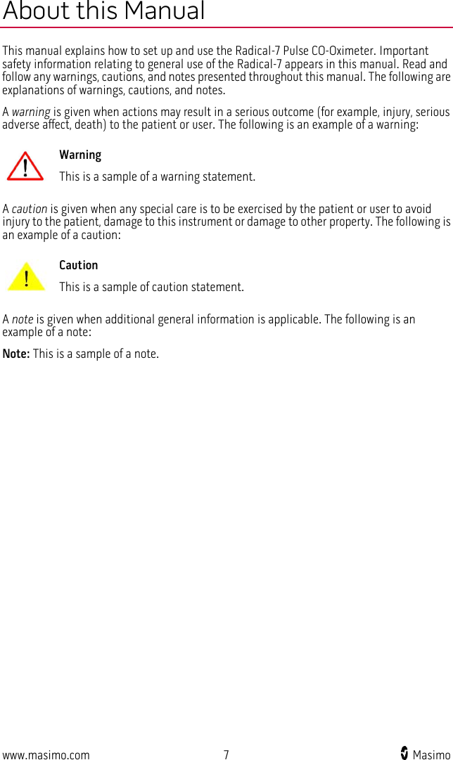
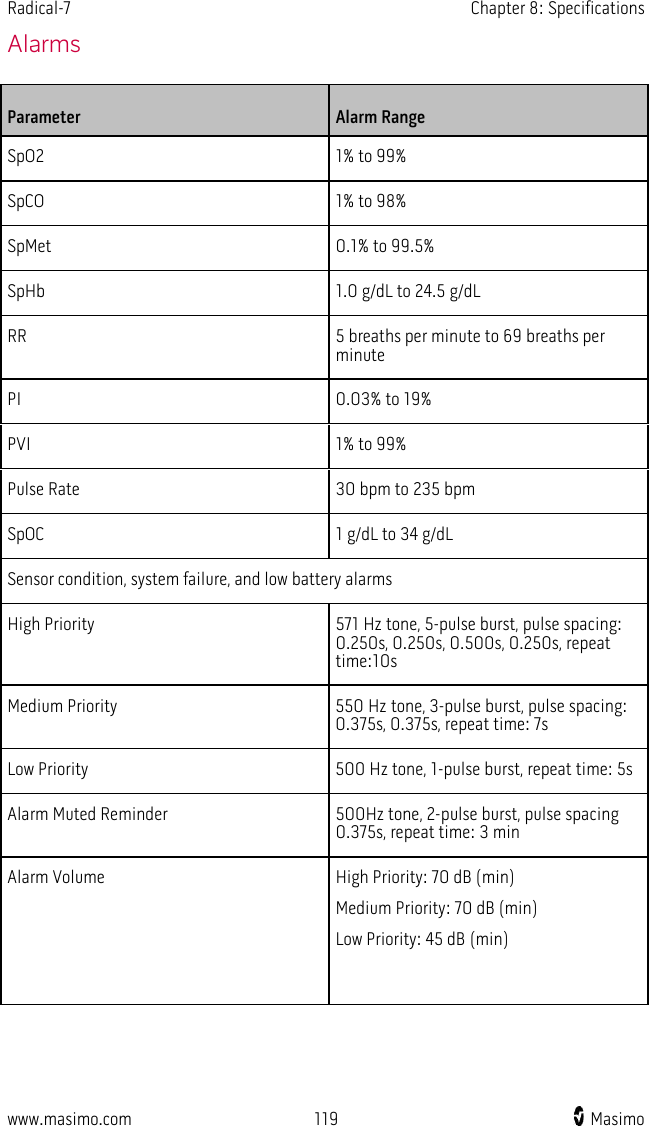
![www.masimo.com 115 Masimo Chapter 8: Specifications The following chapter contains specifications for the Radical-7 Handheld, compatible Docking Stations, and the Standalone system. Measurement Range Measurement Display Range SpO2 (Oxygen Saturation) 0% to 100% SpMet (Methemoglobin) 0% to 99.9% SpCO (Carboxyhemoglobin) 0% to 99% SpHb (Hemoglobin) 0 g/dL to 25.0 g/dL SpOC (Oxygen Content) 0 ml of O2/dL to 35 ml of O2/dL of blood PR (Pulse Rate) 25 bpm to 240 bpm PI (Perfusion Index) 0.02% to 20% PVI (Pleth Variability Index) 0% to 100% RRa (Respiration Rate) 0 breaths per minute to 70 breaths per minute RRp (Respiration Rate) 0 breaths per minute to 70 breaths per minute Accuracy Oxygen Saturation Accuracy [1] No Motion 60% to 80% Adults, Infants, Pediatrics ±3%](https://usermanual.wiki/Masimo/RAD7A/User-Guide-2552569-Page-117.png)
![Radical-7 Chapter 8: Specifications www.masimo.com 116 Masimo No Motion [2] 70% to 100% Adults, Infants, Pediatrics ± 2% Neonates ± 3% Motion [3] 70% to 100% Adults, Infants, Pediatrics, Neonates ± 3% Low Perfusion [4] Adults, Infants, Pediatrics, Neonates ± 2% Pulse Rate Accuracy Pulse rate range 25 bpm to 240 bpm No Motion Adults, infants, pediatrics, neonates ± 3 bpm Motion [4] Adults, infants, pediatrics, neonates ± 5 bpm Low Perfusion Adults, infants, pediatrics, neonates ± 3 bpm Carboxyhemoglobin Accuracy [1] Adults, infants, pediatrics 1% to 40% ± 3% Methemoglobin Saturation Accuracy [1] Adults, infants, pediatrics, neonates 1% to 15% ± 1% Total Hemoglobin Accuracy [6] Adults, pediatrics 8 g/dL to 17 g/dL ±1 g/dL](https://usermanual.wiki/Masimo/RAD7A/User-Guide-2552569-Page-118.png)
![Radical-7 Chapter 8: Specifications www.masimo.com 117 Masimo Respiratory Rate Accuracy (RRa) [11] Adults, pediatrics 0 breaths per minute to 70 breaths per minute, ±1 breath per minute Respiratory Rate Accuracy (RRp) [11] Adults, pediatrics 0 breaths per minute to 70 breaths per minute, ±1 breath per minute Resolution Parameter Step Size %SpO2 1% %SpCO 1% %SpMet 0.1% SpHb g/dL 0.1 g/dL Pulse Rate 1 beats per minute Respiration Rate 1 breath per minute Electrical Standalone AC Power requirements 100 to 240 VAC, 47 to 63 Hz Power consumption 55 VA Fuses 1 Amp, Fast Acting, Metric, (5x20mm), 250V Handheld Battery Type Lithium ion](https://usermanual.wiki/Masimo/RAD7A/User-Guide-2552569-Page-119.png)
![Radical-7 Chapter 8: Specifications www.masimo.com 118 Masimo Capacity 4 hours [7] Time 3 hours Environmental Operating Temperature 32°F to 122°F (0°C to 50°C) Transport/Storage Temperature -40°F to 158°F (-40°C to 70°C) [8] Operating Humidity 10% to 95%, non-condensing Operating Altitude 500 mbar to 1060 mbar -1000 ft to 18,000 ft (-304 m to 5,486 m) Physical Characteristics Dimensions Handheld 8.9” x 3.5” x 2.1” (22.6 cm x 8.9cm x 5.3 cm) Standalone 3.5” x 10.5” x 7.7” (8.9 cm x 26.7 cm x 19.6 cm) Weight Handheld 1.2 lbs. (0.54 kg) Docking Station (RDS-1, RDS-2, RDS-3) 2.5 lbs. (1.14 kg) Standalone (RDS-1, RDS-2, RDS-3) 3.8 lbs. (1.73 kg) Trending • Max of 96 hours of trending at 2-second resolution Sensitivity NORM, MAX, and APOD [10]](https://usermanual.wiki/Masimo/RAD7A/User-Guide-2552569-Page-120.png)

![Radical-7 Chapter 8: Specifications www.masimo.com 129 Masimo Citations [1] SpO2, SpCO, and SpMet accuracy was determined by testing on healthy adult volunteers in the range 60% to 100% SpO2, 0% to 40% SpCO, and 0% to 15% SpMet against a laboratory CO-Oximeter. SpO2 and SpMet accuracy was determined on 16 neonatal NICU patients ranging in age from 7 days to 135 days old and weighting between 0.5 kgs and 4.25 kgs. Seventy-nine (79) data samples were collected over a range of 70% to 100% SaO2 and 0.5% to 2.5% HbMet with a resultant accuracy of 2.9% SpO2 and 0.9% SpMet. Contact Masimo for testing specifications. [2] The Masimo Rainbow SET technology with Masimo sensors has been validated for no motion accuracy in human blood studies on healthy adult male and female volunteers with light to dark skin pigmentation in induced hypoxia studies in the range of 70-100% SpO2 against a laboratory CO-Oximeter and ECG monitor. This variation equals plus or minus one standard deviation which encompasses 68% of the population weight. [3] The Masimo Rainbow SET technology with Masimo sensors has been validated for motion accuracy in human blood studies on healthy adult male and female volunteers with light to dark skin pigmentation in induced hypoxia studies while performing rubbing and touching motions, at 2 to 4 Hz at an amplitude of 1 to 2 cm and a non-repetitive motion between 1 to 5 Hz at an amplitude of 2 to 3 cm in induced hypoxia studies in the range of 70-100% SpO2 against a laboratory CO-Oximeter and ECG monitor. This variation equals plus or minus one standard deviation. Plus or minus one standard deviation encompasses 68% of the population. [4] The Radical-7 has been validated for low perfusion accuracy in bench-top testing against a Biotek Index 2TM* simulator and Masimo's simulator with signal strengths of greater than 0.02% and transmission of greater than 5% for saturations ranging from 70-100%. This variation equals plus or minus one standard deviation. Plus or minus one standard deviation encompasses 68% of the population. [5] Masimo Rainbow SET technology with Masimo sensors has been validated for pulse rate accuracy for the range of 25-240 bpm in bench top testing against a Biotek Index 2 simulator. This variation equals plus or minus one standard deviation which encompasses 68% of the population. [6] SpHb accuracy has been validated on healthy adult male and female volunteers and on surgical patients with light to dark skin pigmentation in the range of 8 g/dL to 17 g/dL SpHb against a laboratory CO-Oximeter. The variation equals plus or minus one standard deviation which encompasses 68% of the population. The SpHb accuracy has not been validated with motion or low perfusion. [7] This represents approximate run time at the lowest indicator brightness and pulse tone turned off using a fully charged battery. [8] If the batteries are to be stored for extended periods of time, it is recommended that they be stored between -20°C to +30°C, and at a relative humidity less than 85%. If stored for a prolonged period at environmental conditions beyond these limits, overall battery capacity may be diminished, and lifetime of the batteries may be shortened. [9] With FastSat the averaging time is dependent on the input signal. For the 2 and 4 second settings the averaging time may range from 2-4 and 4-6 seconds, respectively. [10] Maximum sensitivity mode fixes perfusion limit to 0.02%. [11] Respiration rate accuracy for the Masimo Acoustic Respiration Sensor and Instrument has been validated for the range of 4 to 70 breaths per minute in bench top testing. Clinical validation for up to 30 breaths per minute was also performed with the Masimo Acoustic Respiration Sensor and Instrument. *Registered trademark of Fluke Biomedical Corporation, Everett, Washington.](https://usermanual.wiki/Masimo/RAD7A/User-Guide-2552569-Page-131.png)