User Manual
Radical-7
Operator's Manual
www.masimo.com 1 Masimo
The Radical-7 operating instructions provide the necessary information for proper operation
of all models of the Radical-7 Pulse CO-Oximeter system. There may be information provided
in this manual that is not relevant for your system. General knowledge of pulse oximetry and
an understanding of the features and functions of the Radical-7 are prerequisites for its
proper use. Do not operate the Radical-7 without completely reading and understanding the
instructions in this manual.
NOTICE:
Purchase or possession of this instrument does not carry any express or implied license to use
this instrument with replacement parts which would, alone or in combination with this
instrument, fall within the scope of one of the patents relating to this instrument.
Caution
Federal law restricts this device to sale by or on the order of a physician.
Wireless Radio
FCC ID: VKF-RAD7A, IC: 7362A-RAD7A
Masimo Corporation
40 Parker
Irvine, CA 92618, USA
Tel.: 949-297-7000
Fax.: 949-297-7001
www.masimo.com
EU authorized representative for Masimo Corporation:
MDSS GmbH
Schiffgraben 41
D-30175 Hannover, Germany
Medical electrical equipment with respect to electric shock, fire and mechanical
hazards only in accordance with UL 60601-1/CAN/CSA C22.2 No. 601.1
Patents: www.masimo.com/patents.htm
© 2012 Masimo Corporation
®, Adaptive Probe Off Detection®, APOD®, Discrete Saturation Transform®, DST®,
FastSat®, FST®, Masimo®, Pulse Oximeter®, PVI®, rainbow®, SatShare®, SET®, Signal
Extraction Technology®, Signal IQ®, SpCO®, SpHb®, SpMet® are federally registered
trademarks of Masimo Corporation.
Adaptive Threshold Alarm™, In Vivo Adjustment™, Pleth Variability Index™, Radical-7™,
Rainbow Acoustic Monitoring™, rainbow Resposable™, RDS™, RRa™, RRp™,SafetyNet™, SpOC™
are trademarks of Masimo Corporation. All other trademarks and registered trademarks are
property of their respective owners. The use of the trademarks PATIENT SAFETYNET and PSN
is under license from University HealthSystem Consortium.

www.masimo.com 3 Masimo
Contents
About this Manual -------------------------------------------------------------------------------------------7
Product Description, Indications for Use, Contraindications, and Features ---------------------- 9
Product Description ------------------------------------------------------------------------------------- 9
Indications for Use ------------------------------------------------------------------------------------- 10
Contraindications -------------------------------------------------------------------------------------- 10
Safety Information, Warnings, and Cautions ---------------------------------------------------------- 11
Parameter Related Safety Information, Warnings, and Cautions ------------------------------ 11
Device Related Safety Information, Warnings, and Cautions----------------------------------- 14
Electrical Safety Information, Warnings, and Cautions ----------------------------------------- 18
Alarm Related Safety Information, Warnings, and Cautions ---------------------------------- 20
Sensor Related Safety Information, Warnings, and Cautions ---------------------------------- 21
Chapter 1: Technology Overview ------------------------------------------------------------------------ 23
Signal Extraction Technology (SET) ---------------------------------------------------------------- 23
rainbow Pulse CO-Oximetry Technology ----------------------------------------------------------- 25
rainbow Acoustic Monitoring (RAM) Technology ------------------------------------------------- 29
Chapter 2: Radical-7 Descriptions --------------------------------------------------------------------- 33
General System Description ------------------------------------------------------------------------- 33
Functionality of the Radical-7 ------------------------------------------------------------------------ 34
Handheld ----------------------------------------------------------------------------------------------- 35
Standalone ---------------------------------------------------------------------------------------------- 37
Monitor Interface With SatShare ------------------------------------------------------------------- 40
Chapter 3: Setup ------------------------------------------------------------------------------------------- 41
Unpacking and Inspection --------------------------------------------------------------------------- 41
Docking Station Power Requirements -------------------------------------------------------------- 41
Setting Up the Docking Station --------------------------------------------------------------------- 41
Initial Battery Charging ------------------------------------------------------------------------------- 42
Setting Up for Philips, Agilent, or HP VueLink ---------------------------------------------------- 42
Setting Up for SpaceLabs Flexport ------------------------------------------------------------------ 43
Setting Up and Using SatShare --------------------------------------------------------------------- 44
Chapter 4: Operation -------------------------------------------------------------------------------------- 45
Using the Touchscreen and Buttons ---------------------------------------------------------------- 45

Radical-7 Contents
www.masimo.com 4 Masimo
Using Screen Lock ------------------------------------------------------------------------------------- 46
Using the Home Button ------------------------------------------------------------------------------ 46
Navigating the Radical-7 ----------------------------------------------------------------------------- 47
About the Display View ------------------------------------------------------------------------------- 48
Sensitivity Modes Overview -------------------------------------------------------------------------- 55
Changing Sensitivity Modes ------------------------------------------------------------------------- 56
Accessing the Main Menu ---------------------------------------------------------------------------- 57
Navigating the Main Menu--------------------------------------------------------------------------- 57
Parameter Settings ------------------------------------------------------------------------------------ 59
Sounds --------------------------------------------------------------------------------------------------- 74
Device Settings ----------------------------------------------------------------------------------------- 75
Trends ---------------------------------------------------------------------------------------------------- 81
About ----------------------------------------------------------------------------------------------------- 91
Chapter 5: Profiles ----------------------------------------------------------------------------------------- 93
Profiles Overview --------------------------------------------------------------------------------------- 93
Changing Profiles -------------------------------------------------------------------------------------- 94
Replacing Factory Default Settings for Adult and Neo Profiles -------------------------------- 97
Powering Off the Radical-7 --------------------------------------------------------------------------- 98
Chapter 6: Alarms and Messages ----------------------------------------------------------------------- 99
About Alarms ------------------------------------------------------------------------------------------- 99
Silencing the Alarms ---------------------------------------------------------------------------------- 99
Adaptive Threshold Alarm (ATA) Feature ------------------------------------------------------- 101
3D Alarms --------------------------------------------------------------------------------------------- 102
Messages ---------------------------------------------------------------------------------------------- 104
Chapter 7: Troubleshooting ----------------------------------------------------------------------------- 111
Troubleshooting Measurements-------------------------------------------------------------------- 111
Troubleshooting the Radical-7 --------------------------------------------------------------------- 113
Chapter 8: Specifications ------------------------------------------------------------------------------- 115
Measurement Range --------------------------------------------------------------------------------- 115
Accuracy ------------------------------------------------------------------------------------------------ 115
Resolution ---------------------------------------------------------------------------------------------- 117
Electrical------------------------------------------------------------------------------------------------ 117
Environmental ----------------------------------------------------------------------------------------- 118
Physical Characteristics ----------------------------------------------------------------------------- 118

Radical-7 Contents
www.masimo.com 5 Masimo
Trending ----------------------------------------------------------------------------------------------- 118
Alarms -------------------------------------------------------------------------------------------------- 119
Display Indicators ------------------------------------------------------------------------------------ 120
Compliance --------------------------------------------------------------------------------------------- 121
Output Interface -------------------------------------------------------------------------------------- 122
Wireless Radio (If Installed) ----------------------------------------------------------------------- 122
Serial Interface Specifications --------------------------------------------------------------------- 122
Serial Interface Setup ------------------------------------------------------------------------------- 123
Analog Output and Nurse Call Specifications --------------------------------------------------- 124
Symbols ------------------------------------------------------------------------------------------------ 126
Country Codes (FCC and EU) ------------------------------------------------------------------------ 127
Citations ----------------------------------------------------------------------------------------------- 129
Chapter 9: Service and Maintenance----------------------------------------------------------------- 131
Cleaning ----------------------------------------------------------------------------------------------- 131
Battery Operation and Maintenance ------------------------------------------------------------- 131
Performance Verification --------------------------------------------------------------------------- 134
Repair Policy ------------------------------------------------------------------------------------------ 136
Return Procedure ------------------------------------------------------------------------------------- 136
Contacting Masimo ---------------------------------------------------------------------------------- 136
Appendix: Best Practices for Comparisons to Reference Measurements ----------------------- 139
Best Practices Checklist for Continuous SpHb Comparisons --------------------------------- 139
Best Practices Checklist for SpCO Comparisons ------------------------------------------------ 142
Best Practices Checklist for Acoustic Respiration Rate Comparisons ----------------------- 144
Index ------------------------------------------------------------------------------------------------------- 149

www.masimo.com 7 Masimo
About this Manual
This manual explains how to set up and use the Radical-7 Pulse CO-Oximeter. Important
safety information relating to general use of the Radical-7 appears in this manual. Read and
follow any warnings, cautions, and notes presented throughout this manual. The following are
explanations of warnings, cautions, and notes.
A warning is given when actions may result in a serious outcome (for example, injury, serious
adverse affect, death) to the patient or user. The following is an example of a warning:
Warning
This is a sample of a warning statement.
A caution is given when any special care is to be exercised by the patient or user to avoid
injury to the patient, damage to this instrument or damage to other property. The following is
an example of a caution:
Caution
This is a sample of caution statement.
A note is given when additional general information is applicable. The following is an
example of a note:
Note: This is a sample of a note.

www.masimo.com 9 Masimo
Product Description, Indications for Use,
Contraindications, and Features
The following chapter contains the Radical-7 product description, key features and benefits,
indications for use, contraindications, and safety information, including cautions, warnings,
and notes.
Product Description
The Radical-7 is a noninvasive monitor that measures arterial oxygen saturation (SpO2),
pulse rate (PR), and perfusion index (PI), along with optional measurements of hemoglobin
(SpHb), carboxyhemoglobin (SpCO), total oxygen content (SpOC), methemoglobin (SpMet),
Pleth Variability Index (PVI), Acoustic Respiration Rate (RRa), and Pleth Respiration Rate
(RRp).
The Radical-7 can be used as either a Handheld or a Standalone monitor. The Radical-7
features a touchscreen Liquid Crystal Display (LCD) that continuously displays numeric values
for all parameters.
The Radical-7 provides graphical displays for plethysmographic waveform, respiratory
waveform, Signal Identification and Quality Indicator (Signal IQ).
The Radical-7 can also be used to interface with a multi-parameter patient monitor to send
Masimo SET pulse oximetry information to that monitor for display.
The Radical-7 has an embedded 802.11 wireless radio that can be used for connectivity.
Key Features
The following features are available for the Radical-7. Some features are optional:
• Masimo SET is clinically proven to satisfy all sensitivity and specificity
requirements for pulse oximeter technology.
• Rainbow technology uses 7+ wavelengths of light to continuously and
noninvasively measure carboxyhemoglobin (SpCO), methemoglobin (SpMet), and
total hemoglobin (SpHb), as well as providing a more reliable probe-off detection.
• Total oxygen content (SpOC) provides a calculated measurement of the amount of
oxygen in arterial blood, which may provide useful information about oxygen both
dissolved in plasma and combined with hemoglobin.
• Perfusion Index (PI) with trending capability indicates arterial pulse signal
strength and may be used as a diagnostic tool during low perfusion.
• Pleth Variability Index (PVI) may show changes that reflect physiologic factors
such as vascular tone, circulating blood volume, and intrathoracic pressure
excursions. [The utility of PVI is unknown at this time and requires further clinical
studies. Technical factors that may affect PVI include probe malposition and
patient motion.]
• Respiration rate can be determined by the acoustic (RRa) or plethysmographic
waveform (RRp).

Radical-7 Product Description, Indications for Use, Contraindications, and Features
www.masimo.com 10 Masimo
• Signal IQ waveform for signal identification and quality indication during
excessive motion and low signal to noise situations.
• FastSat tracks rapid changes in arterial O2.
• Variable pitch provides tonal variance for every 1% change in saturation.
• SatShare interface allows transfer of SpO2 and pulse rate to an existing
multi-parameter monitor and allows for the reading of SpCO, SpMet, SpHb, and
SpOC on adjacent Radical-7 monitor.
• Automatic screen rotation provides upright display for vertical or horizontal
monitor positioning.
• Multi-gesture touchscreen interface.
• Detachable portable Handheld for patient transport.
• Remote alarm interface.
Indications for Use
The Masimo Radical-7 and accessories are indicated for the continuous noninvasive
monitoring of functional oxygen saturation of arterial hemoglobin (SpO2), pulse rate (PR),
carboxyhemoglobin saturation (SpCO), methemoglobin saturation (SpMet), total hemoglobin
concentration (SpHb), and/or respiratory rate (RRa).
The Masimo Radical-7 and accessories have been validated and are indicated for use with
adult, pediatric, and neonatal patients during both no motion and motion conditions, and for
patients who are well or poorly perfused in hospitals, hospital-type facilities, mobile, and
home environments.
In addition, the Masimo Radical-7 and accessories are indicated to provide the continuous
noninvasive monitoring data obtained from the Masimo rainbow SET Radical 7 Pulse
CO-Oximeter and accessories of functional oxygen saturation of arterial hemoglobin (SpO2)
and pulse rate (PR) to multi-parameter devices for the display of those devices.
Contraindications
The Radical-7 is not intended for use as an apnea monitor.
www.masimo.com 11 Masimo
Safety Information, Warnings, and
Cautions
The following section lists warnings, caution, notes, and safety information.
The Radical-7 is designed to minimize the possibility of hazards from errors in the software
program by following sound Engineering Design Processes, Risk Analysis and Software
Validation.
The Radical-7 is to be operated by qualified personnel only. The manual, accessories,
directions for use, all precautionary information, and specifications should be read before use.
Always use the Radical-7 precisely in accordance with the directions in this manual,
including finger selection, finger alignment in the sensor, and subject behavior during
testing. Failure to follow all of the directions in this manual could lead to inaccurate
measurements.
Caution
For SpHb, the Radical-7 should be considered an early warning device. Blood
samples should be analyzed by laboratory instruments prior to clinical
decision making to completely understand the patient’s condition.
Caution
Variation in hemoglobin measurements may be profound and may be affected
by sample type, body positioning, as well as other physiological conditions.
As with most hemoglobin tests, Radical-
7 test results should be scrutinized in
light of a specific patient’s condition. Any results exhibiting inconsistency
with the patient’s clinical status should be repeated and/or supplemented
with additional test data.
Parameter Related Safety Information, Warnings, and
Cautions
This section contains parameter related safety information.
Warning
Interfering Substances: Dyes, or any substance containing dyes, that change
usual blood pigmentation may cause erroneous readings.
Warning
SpO2, SpCO, SpMet, and SpHb are empirically calibrated in healthy adult
volunteers with normal levels of carboxyhemoglobin (COHb) and
methemoglobin (MetHb).

Radical-7 Safety Information, Warnings, and Cautions
www.masimo.com 12 Masimo
Warning
The Radical-7 cannot measure elevated levels of COHb or MetHb.
Warning
Inaccurate SpO2 readings may be caused by:
• Elevated levels of COHb and MetHb
• For increased COHb: COHb levels above normal tend to increase
the level of SpO2. The level of increase is approximately equal
to the amount of COHb that is present.
• Note: High levels of COHb may occur with a seemingly normal
SpO2. When elevated levels of COHb are suspected, laboratory
analysis (CO-Oximetry) of a blood sample should be performed.
• For increased MetHb: the SpO2
may be decreased by levels of MetHb
of up to approximately 10% to 15%. At higher levels of MetHb, the
SpO2 may tend to read in the low to mid 80s. W
hen elevated levels of
MetHb are suspected, laboratory analysis (CO-Oximetry) of a blood
sample should be performed.
• Intravascular dyes such as indocyanine green or methylene blue
• Externally applied coloring and texture such as nail polish, acrylic
nails, glitter, etc.
• Elevated levels of bilirubin
• Severe anemia
• Low arterial perfusion
• Motion artifact

Radical-7 Safety Information, Warnings, and Cautions
www.masimo.com 13 Masimo
Warning
Inaccurate SpHb and SpOC readings may be caused by:
• Intravascular dyes such as indocyanine green or methylene blue
• Externally applied coloring and texture such as nail polish, acrylic
nails, glitter, etc.
• Elevated levels of bilirubin
• Low arterial perfusion
• Motion artifact
• Low arterial oxygen saturation levels
• Elevated carboxyhemoglobin levels
• Elevated methemoglobin levels
• Difference between patient's finger skin and finger core temperature
• Hemoglobin synthesis disorders
• Hemoglobinopathies and synthesis disorders such as thalassemias,
Hb s, Hb c, sickle cell, etc.
• Vasospastic disease such as Raynaud's
• Elevated altitude
• Peripheral vascular disease
• Liver disease
• EMI radiation interference
Warning
Inaccurate SpCO and SpMet readings can be caused by:
• Intravascular dyes such as indocyanine green or methylene blue
• Abnormal hemoglobin levels
• Low arterial perfusion
• Low arterial oxygen saturation levels including altitude induced
hypoxemia
• Elevated total bilirubin levels
• Motion artifact
• SpCO readings may not be provided if SpO2 readings are less than
90%
• SpCO readings may not be provided if SpMet readings are greater
than 2%
Inaccurate SpCO readings can be caused by:
• Levels of methemoglobin approximately 1.5% or above
Radical-7 Safety Information, Warnings, and Cautions
www.masimo.com 14 Masimo
Warning
Inaccurate respiration rate measurements may be caused by:
• Low arterial perfusion
• Motion artifact
• Low arterial oxygen saturation
• Excessive ambient or environmental noise
• Improper sensor placement
Caution
If patient hypoxemia is indicated, blood samples should be analyzed by
laboratory devices to completely understand the patient’s condition.
Caution
Confirm offset values(s) periodically as the difference between the displayed
parameter value and the laboratory reference value may vary over time.
Caution
Do not use In Vivo Adjustment if the monitor displays a Low SpHb SIQ message.
Caution
If the Low Perfusion message is frequently displayed, find a better perfused
monitoring site. In the interim, assess the patient and, if indicated, verify
oxygenation status through other means.
Caution
Changing the SpHb Cal, the date and time of the system clock, or the trend
period clears the data in the trend memory.
Caution
Excessive ambient noise may affect the accuracy of the respiration rate reading
from the Acoustic Respiration Sensor.
When monitoring acoustic respiration, Masimo recommends minimally monitoring both
oxygenation (SpO2) and respiration (RRa).
Device Related Safety Information, Warnings, and Cautions
This section contains device related safety information.
Radical-7 Safety Information, Warnings, and Cautions
www.masimo.com 15 Masimo
Warning
Explosion hazard: Do not use the Radical-7 in the presence of flammable
anesthetics or other flammable substance in combination with air,
oxygen-enriched environments, or nitrous oxide.
Warning
Do not use the Radical-7 or sensor during magnetic resonance imaging (MRI)
scanning.
Warning
Do not place the Radical-7 or accessories in any position that might cause it to
fall on the patient.
Warning
During SatShare operation, do not use the plethysmographic waveform display
on the multi-parameter monitor for diagnostic purposes. Instead, use the
plethysmographic waveform displayed on the Radical-7 screen.
Warning
Pulse rate measurement is based on the optical detection of a peripheral flow
pulse and therefore may not detect certain arrhythmias. The Radical-7 should
not be used as a replacement or substitute for ECG-based arrhythmia analysis.
Warning
The Radical-7 can be used during defibrillation, but the readings may be
inaccurate for up to 20 seconds.
Warning
Do not place containers with liquids on or near the Radical-7. Liquids spilled on
the instrument may cause it to perform inaccurately or fail.
Warning
EMI radiation interference such as computer displays and/or LCD/plasma TVs
can cause error or incorrect measurements on the Radical-7.
Warning
If the Radical-7 fails any part of the setup procedures or leakage spot check,
remove the instrument from operation until qualified service personnel have
corrected the situation.
Warning
A functional tester cannot be used to assess the accuracy of the Radical-7.
Radical-7 Safety Information, Warnings, and Cautions
www.masimo.com 16 Masimo
Warning
Do not autoclave, pressure sterilize, or gas sterilize the Radical-7.
Warning
Do not touch, press, or rub the display panels with abrasive cleaning compounds,
instruments, brushes, rough-surface materials, or bring them into contact with
anything that could scratch the panel.
Warning
Do not use petroleum-based or acetone solutions, or other harsh solvents, to
clean the Radical-7. These substances affect the device’s materials and
instrument failure can result.
Warning
An operator may only perform maintenance procedures specifically described in
the manual. Refer servicing to qualified service personnel trained in the repair of
this equipment.
Warning
SatShare signals are ideal simulated waveforms corresponding to the calculated
saturation and pulse rate values and do contain all of the information contained
in physiological waveforms. The multi-
parameter patient monitor decodes these
signals into saturation and pulse rate values.
Warning
Simultaneous use of SatShare and serial port is not supported.
Caution
Do not place the Radical-7 where the controls can be changed by the patient.
Caution
Disposal of product - Comply with local laws in the disposal of the instrument
and/or its accessories.
Only SpO2 and pulse rate can be displayed on the multi-parameter monitor with Flexport.
If the Radical Docking Station is compatible with SafetyNet, Vuelink is not supported.
Use the Radical-7 in accordance with Environmental Specifications section in of this manual.

Radical-7 Safety Information, Warnings, and Cautions
www.masimo.com 17 Masimo
This device complies with part 15 of the FCC Rules. Operation is subject to the following two
conditions: (1) This device may not cause harmful interference, and (2) this device must
accept any interference received, including interference that may cause undesired operation.
Cleared Use Only: The device and related accessories are cleared by the Food and Drug
Administration (FDA) for noninvasive patient monitoring and may not be used for any
processes, procedures, experiments or any other use for which the device is not intended or
cleared by the FDA, or in any manner inconsistent with the instructions for use or labeling.
Changes or modifications not expressly approved by the party responsible for compliance
could void the user's authority to operate the equipment.
In accordance with international telecommunication requirements, the frequency band of 2.4
GHz and 5.15 to 5.25 Ghz is only for indoor usage to reduce potential for harmful interference
to co-channel mobile satellite systems.
This equipment has been tested and found to comply with the limits for a Class B digital
device, pursuant to part 15 of the FCC Rules. These limits are designed to provide reasonable
protection against harmful interference in a residential installation. This equipment
generates, uses and can radiate radio frequency energy and, if not installed and used in
accordance with the instructions, may cause harmful interference to radio communications.
However, there is no guarantee that interference will not occur in a particular installation. If
this equipment does cause harmful interference to radio or television reception, which can be
determined by turning the equipment off and on, the user is encouraged to try to correct the
interference by one or more of the following measures:
• Reorient or relocate the receiving antenna.
• Increase the separation between the equipment and receiver.
• Connect the equipment into an outlet on a circuit different from that to which the
receiver is connected.
• Consult the dealer or an experienced radio/TV technician for help.
In order to maintain compliance with FCC regulations, shielded cables must be used with this
equipment. Operation with non-approved equipment or unshielded cables is likely to result in
interference to radio and TV reception. The user is cautioned that changes and modifications
made to the equipment without the approval of manufacturer could void the user's authority
to operate this equipment.
To satisfy RF exposure requirements, this device and its antenna must operate with a
separation distance of at least 20 cm from all persons and must not be co-located or
operating in conjunction with any other antenna or transmitter.
This equipment has been tested and found to comply with the limits for medical devices to
the EN 60601-1-2: 2002, Medical Device Directive 93/42/EEC and Class B. These limits are
designed to provide reasonable protection against harmful interference in a typical medical
installation.
This Class B digital apparatus complies with Canadian ICES-003.

Radical-7 Safety Information, Warnings, and Cautions
www.masimo.com 18 Masimo
Electrical Safety Information, Warnings, and Cautions
This section contains electrical related safety information.
Warning
Fire Hazard: To protect against fire hazard,
replace only with fuses of same type,
current rating, and voltage rating.
Caution
Do not place the Radical-7 on electrical equipment that may affect the
instrument, preventing it from working properly.
Caution
Dispose of used batteries according to required country or regional instructions.
Caution
Risk of explosion if battery is replaced with an incorrect type. Replace with
Masimo supplied parts only.
Caution
At Low Battery, connect the Radical-7 to AC power to prevent loss of power.
Caution
Do not incinerate battery.
Caution
Electric shock hazard: Do not open the Radical-7 cover except to replace the
battery or batteries.
Caution
To protect against injury from electric shock, follow the directions below:
• Avoid placing the device on surfaces with visible liquid spills.
• Do not soak or immerse the device in liquids.
• Use cleaning solutions sparingly.
Caution
Electrical shock and flammability hazard: Before cleaning the Radical-7, always
turn it off and disconnect the power cord from the AC power supply.

Radical-7 Safety Information, Warnings, and Cautions
www.masimo.com 19 Masimo
Caution
Do not under any circumstances remove the grounding conductor from the
power plug.
Caution
Do not use extension cords or adapters of any type. The power cord and plug
must be intact and undamaged.
Caution
To ensure patient electrical isolation, connect only to other equipment with
electrically isolated circuits.
Caution
Do not connect to an electrical outlet controlled by a wall switch or dimmer.
All external instrument connections to the Analog Output/Nurse Call connector must be
IEC-60950 compliant.
It is recommended that the Radical-7 Handheld is docked to the Docking Station that is
attached to an AC power source when it is not in use to ensure that the battery remains fully
charged.
External instrument connections to the SatShare port must be IEC-60601-1 compliant.
Only use a SatShare cable that has a ferrite bead installed.
Use the power cord as the means to disconnect the instrument from the main power supply.
If the Radical-7 Handheld has not been used or charged within seven (7) days or more, then
recharge the battery prior to use.
The instrument must be configured to match your local power line frequency to allow for the
cancelation of noise introduced by fluorescent lights and other sources.
If there is any doubt about the integrity of the protective earth conductor arrangement,
operate the Radical-7 on internal battery power until the AC power supply protective
conductor is fully functional.
To prevent damage, do not soak or immerse the sensor in any liquid solution. Do not attempt
to sterilize by irradiation, steam, autoclave or any method other than ethylene oxide as
indicated.
Only SpO2 and pulse rate can be displayed on the multi-parameter monitor with SatShare.
Radical-7 Safety Information, Warnings, and Cautions
www.masimo.com 20 Masimo
The battery should be installed and/or removed from the Radical-7 by qualified personnel
only.
All batteries lose capacity with age, thus the amount of run time at Low Battery will vary
depending upon the age of the battery.
All external device connections to the RS-232 serial port must be IEC-60950 compliant.
The Docking Station battery should be installed and/or removed from the Docking Station
only by qualified personnel.
To conserve battery power, keep the frequency of the audible alarms to a minimum and the
volume to a minimum.
To conserve battery power, keep the back-lit LCD screen at minimum illumination.
When using the SatShare feature, to conserve battery power, always keep the Radical-7 on AC
line power.
Alarm Related Safety Information, Warnings, and Cautions
This section contains alarm related safety information.
Caution
For home use, ensure that the Radical-7 alarm can be heard from other rooms in
the house, especially when noisy appliances such as vacuum cleaners,
dishwashers, clothes dryers, televisions, or radios are operating.
Caution
Do not place the Radical-7 against a surface that may cause the alarm to be
muffled.
Caution
To ensure that alarm limits are appropriate for the patient being monitored,
check the limits each time the Radical-7 is used.
Caution
The Nurse Call feature is disabled when the Audible Alarms are silenced and
Nurse Call setting is set to Alarms.
Caution
When the Radical-7 is placed in All Mute, the patient alarms will not audibly
sound on the Radical-7 or the SafetyNet. The SafetyNet View will display a visual
alarm.
Radical-7 Safety Information, Warnings, and Cautions
www.masimo.com 21 Masimo
Caution
During SatShare operation, the audible alarms may be muted on the Radical-7.
When the audible alarm is muted (indicated by a bell with a slash through it) on
the Radical-7, use the multi-parameter monitor for audible alarm indication.
Caution
If an alarm condition occurs while the Alarm Silence period is set to All Mute, the
only alarm indications will be visual display and symbols related to alarm
condition. No alarm will sound.
The Desat Index alarm is intended as an adjunct rather than in place of the Low Saturation
alarm.
Sensor Related Safety Information, Warnings, and Cautions
This section contains sensor related safety information.
Warning
As with all medical equipment, carefully route patient cabling to reduce the
possibility of patient entanglement or strangulation.
Warning
Always remove the sensor from the patient and completely disconnect the
patient from the Radical-7 before bathing the patient.
Caution
If using the Radical-7 during full body irradiation, keep the sensor out of the
radiation field. If the sensor is exposed to the radiation, the reading might be
inaccurate or the instrument might read zero for the duration of the active
irradiation period.
Do not loop the sensor cable into a tight coil or wrap around the device, as this can damage
the sensor cable.
Patient Safety - If a sensor is damaged in any way, discontinue use immediately.
Failure to apply the sensor properly may lead to incorrect measurements.
Additional information specific to the Masimo sensors compatible with Radical-7, including
information about parameter/measurement performance during motion and low perfusion,
may be found in the sensor's directions for use (DFU).

Radical-7 Safety Information, Warnings, and Cautions
www.masimo.com 22 Masimo
Do not expose the Masimo sensors used with Radical-7 to moisture, liquids or a humid
environment, as this may make the sensor perform inaccurately or fail.
High-intensity extreme lights (including pulsating strobe lights and direct sunlight) directed
on the sensor, may not allow the Radical-7 to obtain readings.
When using the Maximum Sensitivity setting, performance of the Sensor Off detection may be
compromised. If the Radical-7 is in this setting and the sensor becomes dislodged from the
patient, the potential for false readings may occur due to environmental "noise" such as light,
vibration, and excessive air movement.
www.masimo.com 23 Masimo
Chapter 1: Technology Overview
The following chapter contains general descriptions about parameters, measurements, and
the technology used by Masimo products.
Signal Extraction Technology (SET)
Masimo Signal Extraction Technology's signal processing differs from that of conventional
pulse oximeters. Conventional pulse oximeters assume that arterial blood is the only blood
moving (pulsating) in the measurement site. During patient motion, however, the venous
blood also moves, causing conventional pulse oximeters to read low values, because they
cannot distinguish between the arterial and venous blood movement (sometimes referred to
as noise).
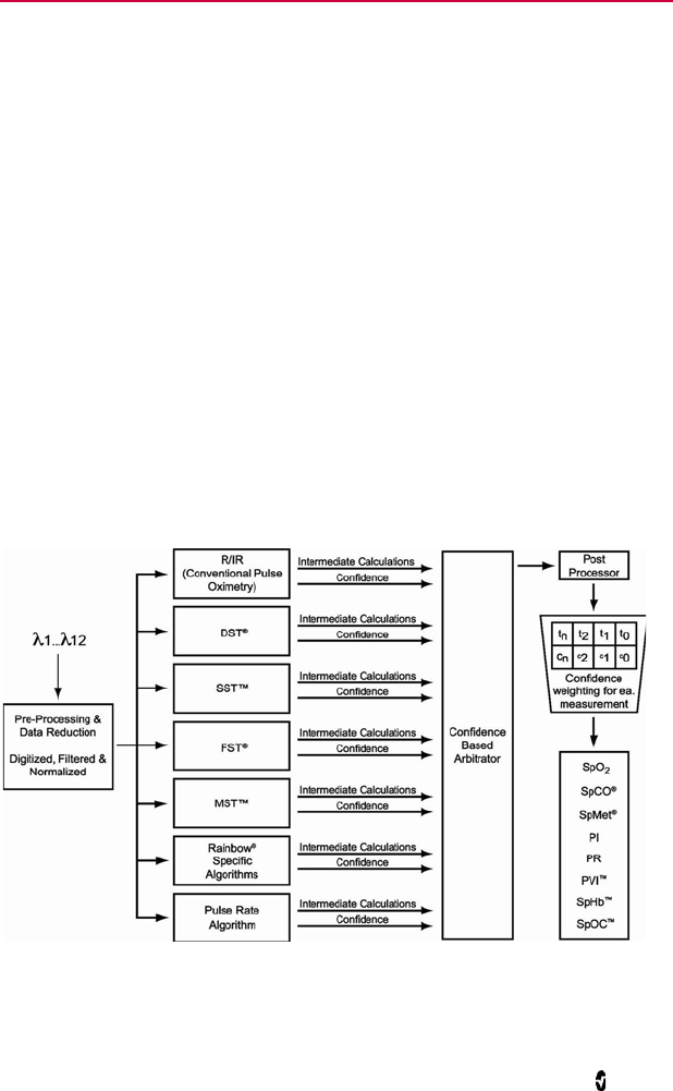
Masimo SET pulse oximetry utilizes parallel engines and adaptive digital filtering. Adaptive
filters are powerful because they are able to adapt to the varying physiologic signals and/or
noise and separate them by looking at the whole signal and breaking it down to its
fundamental components. The Masimo SET signal processing algorithm, Discrete Saturation
Transform® (DST®), in parallel with Fast Saturation Transform (FST®), reliably identifies the
noise, isolates it and, using adaptive filters, cancels it. It then reports the true arterial oxygen
saturation for display on the monitor.
Masimo rainbow SET Parallel Engines
This figure is for conceptual purposes only.
Radical-7 Chapter 1: Technology Overview
www.masimo.com 24 Masimo
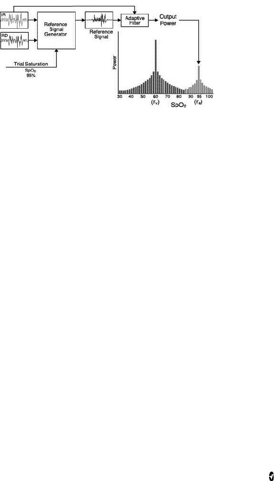
Masimo SET DST
This figure is for conceptual purposes only.
General Description for Oxygen Saturation (SpO2)
Pulse oximetry is governed by the following principles:
1. Oxyhemoglobin (oxygenated blood) and deoxyhemoglobin (non-oxygenated
blood) differ in their absorption of red and infrared light (spectrophotometry).
2. The amount of arterial blood in tissue changes with your pulse
(photoplethysmography). Therefore, the amount of light absorbed by the varying
quantities of arterial blood changes as well.
3. As a plethysmographic waveform
Successful Monitoring for SpO2, PR, and PI
Stability of the SpO2 readings may be a good indicator of signal validity. Although stability is
a relative term, experience will provide a good feeling for changes that are artifactual or
physiological and the speed, timing, and behavior of each.
The stability of the readings over time is affected by the averaging mode being used. The
longer the averaging time, the more stable the readings tend to become. This is due to a
dampened response as the signal is averaged over a longer period of time than during shorter
averaging times. However, longer averaging times delay the response of the oximeter and
reduce the measured variations of SpO2 and pulse rate.
Functional Oxygen Saturation
The Radical-7 is calibrated to measure and display functional oxygen saturation (SpO2): the
amount of oxyhemoglobin expressed as a percentage of the hemoglobin that is available to
transport oxygen.
Note that carboxyhemoglobin is not capable of transporting oxygen, but is recognized as
oxygenated hemoglobin by conventional pulse oximetry.
Radical-7 Chapter 1: Technology Overview
www.masimo.com 25 Masimo
General Description for Pulse Rate (PR)
Pulse rate (PR) , measured in beats per minute (BPM) is based on the optical detection of
peripheral flow pulse.
General Description for Perfusion Index (PI)
The Perfusion Index (PI) is the ratio of the pulsatile blood flow to the non-pulsatile or static
blood in peripheral tissue. PI thus represents a noninvasive measure of peripheral perfusion
that can be continuously and noninvasively obtained from a pulse oximeter.
General Description for Pleth Variability Index (PVI)
The pleth variability index (PVI) is a measure of the dynamic changes in the perfusion index
(PI) that occur during the respiratory cycle. The calculation is accomplished by measuring
changes in PI over a time interval where one or more complete respiratory cycles have
occurred. PVI is displayed as a percentage (0-100%).
The utility of PVI is unknown at this time and requires further clinical studies. Technical
factors that may affect PVI include probe malposition and patient motion.
rainbow Pulse CO-Oximetry Technology
rainbow Pulse CO-Oximetry technology is governed by the following principles:
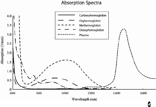
1. Oxyhemoglobin (oxygenated blood), deoxyhemoglobin (non-oxygenated blood),
carboxyhemoglobin (blood with carbon monoxide content), methemoglobin
(blood with oxidized hemoglobin) and blood plasma constituents differ in their
absorption of visible and infrared light (using spectrophotometry).
2. The amount of arterial blood in tissue changes with pulse
(photoplethysmography). Therefore, the amount of light absorbed by the varying
quantities of arterial blood changes as well.

Radical-7 Chapter 1: Technology Overview
www.masimo.com 26 Masimo
The Radical-7 uses a multi-wavelength sensor to distinguish between oxygenated blood,
deoxygenated blood, blood with carbon monoxide, oxidized blood and blood plasma.
The Radical-7 utilizes a sensor with various light-emitting diodes (LEDs) that pass light
through the site to a diode (detector). Signal data is obtained by passing various visible and
infrared lights (LEDs, 500 to 1400nm) through a capillary bed (for example, a fingertip, a
hand, a foot) and measuring changes in light absorption during the blood pulsatile cycle. This
information may be useful to clinicians. The maximum radiant power of the strongest light is
rated at ≤ 25 mW. The detector receives the light, converts it into an electronic signal and
sends it to the Radical-7 for calculation.
1. Light Emitting Diodes (LEDs)
(7 + wavelengths)
2. Detector
Once the Radical-7 receives the signal from the sensor, it utilizes proprietary algorithms to
calculate the patient’s functional oxygen saturation (SpO2 [%]), blood levels of
carboxyhemoglobin (SpCO [%]), methemoglobin (SpMet [%]), total hemoglobin concentration
(SpHb [g/dL]) and pulse rate (PR). The SpCO, SpMet and SpHb measurements rely on a
multi-wavelength calibration equation to quantify the percentage of carbon monoxide and
methemoglobin and the concentration of total hemoglobin in arterial blood. In an ambient
temperature of 35º C the maximum skin surface temperature has been measured at less than
106º F (41º C), verified by Masimo sensor skin temperature test procedure.
Pulse CO-Oximetry vs. Drawn Whole Blood Measurements
When SpO2, SpCO, SpMet, and SpHb measurements obtained from the Radical-7
(noninvasive) are compared to drawn whole blood (invasive) measurements by blood gas
and/or laboratory CO-Oximetry methods, caution should be taken when evaluating and
interpreting the results.
The blood gas and/or laboratory CO-Oximetry measurements may differ from the SpO2, SpCO,
SpMet, SpHb, and SpOC measurements of the Radical-7. Any comparisons should be
simultaneous, meaning the measurement on the device should be noted at the exact time
that blood is drawn.
In the case of SpO2, different results are usually obtained from the arterial blood gas sample
if the calculated measurement is not appropriately corrected for the effects of variables that
shift the relationship between the partial pressure of oxygen (PO2) and saturation, such as:
pH,temperature, the partial pressure of carbon dioxide (PCO2), 2,3-DPG, and fetal
hemoglobin. In the case of SpCO, different results are also expected if concentration of
methemoglobin in the blood gas sample is abnormal (greater than 2% for methemoglobin
concentration).
High levels of bilirubin may cause erroneous SpO2, SpMet, SpCO, and SpHb readings. As
blood samples are usually taken over a period of 20 seconds (the time it takes to draw the

Radical-7 Chapter 1: Technology Overview
www.masimo.com 27 Masimo
blood) a meaningful comparison can only be achieved if the oxygen saturation,
carboxyhemoglobin, and methemoglobin concentration of the patient are stable and not
changing over the period of time that the blood gas sample is taken. Subsequently, blood gas
and laboratory CO-Oximetry measurements of SpO2, SpCO, SpMet, SpHb, and SpOC may vary
with the rapid administration of fluids and in procedures such as dialysis. Additionally, drawn
whole blood testing can be affected by sample handling methods and time elapsed between
blood draw and sample testing.
Measurements with Low Signal IQ should not be compared to laboratory measurements.
General Description for Total Hemoglobin (SpHb)
Pulse CO-Oximetry is a continuous and noninvasive method of measuring the levels of total
hemoglobin (SpHb) in arterial blood. It relies on the same principles of pulse oximetry to
make its SpHb measurement. The measurement is taken by a sensor capable of measuring
SpHb, usually on the fingertip for adult and pediatric patients.
The sensor connects directly to the Pulse CO-Oximeter or with a patient cable. The sensor
collects signal data from the patient and sends it to the instrument. The instrument displays
the calculated data as measurement of total hemoglobin concentration.
Successful Monitoring for SpHb
A stable SpHb reading is associated with correct sensor placement, small physiological
changes during the measurement and acceptable levels of arterial perfusion at the
measurement site. Physiological changes at the measurement site are mainly caused by
fluctuations in the oxygen saturation, blood concentration and perfusion. See Safety
Information, Warnings, and Cautions on page 11 and Troubleshooting Measurements on
page 111.
General Description for Total Arterial Oxygen Content (CaO2)
Oxygen (O2) is carried in the blood in two forms, either dissolved in plasma or combined with
hemoglobin. The amount of oxygen in the arterial blood is termed the oxygen content (CaO2)
and is measured in units of ml O2/dL blood. One gram of hemoglobin (Hb) can carry 1.34 ml
of oxygen, whereas 100 ml of blood plasma may carry approximately 0.3 ml of oxygen*. The
oxygen content is determined mathematically as:
CaO2 = 1.34 (ml O2/g Hb) x Hb (g/dL) x HbO2 + PaO2 (mm Hg) x (0.3 ml O2/100 mm Hg/dL)
Where HbO2 is the fractional arterial oxygen saturation and PaO2 is the partial pressure of
arterial oxygen.
For typical PaO2 values, the second part of the above equation (PaO2 [mm Hg] x [0.3 ml O2/
100 mm Hg/dL]) is approximately 0.3 ml/dL. Furthermore, for typical carboxyhemoglobin
and methemoglobin levels, the functional saturation (SpO2) as measured by a pulse oximeter
is given by:
SpO2 = 1.02 x HbO2
*Martin, Laurence. All You Really Need to Know to Interpret Arterial Blood Gases, Second
Edition. New York: Lippincott Williams & Wilkins, 1999.

Radical-7 Chapter 1: Technology Overview
www.masimo.com 28 Masimo
General Description for SpOC
The above approximations result in the following reduced equation for oxygen content via the
Pulse CO-Oximeter:
SpOC (ml/dL*) = 1.31 (ml O2/g Hb) x SpHb (g/dL) x SpO2 + 0.3 ml/dL
*When ml O2/g Hb is multiplied by g/dL of SpHb, the gram unit in the denominator of ml/g
cancels the gram unit in the numerator of g/dL resulting in ml/dL (ml of oxygen in one dL of
blood) as the unit of measure for SpOC. See Safety Information, Warnings, and Cautions on
page 11.
General Description for Carboxyhemoglobin (SpCO)
Pulse CO-Oximetry is a continuous and noninvasive method of measuring the levels of
carboxyhemoglobin concentration (SpCO) in arterial blood. It relies on the same basic
principles of pulse oximetry (spectrophotometry) to make its SpCO measurement.
The measurement is obtained by placing a sensor on a patient, usually on the fingertip for
adults and the hand or foot for infants. The sensor connects either directly to the Pulse
CO-Oximetry instrument or through an instrument patient cable.
The sensor collects signal data from the patient and sends it to the instrument. The
instrument displays the calculated data as percentage value for the SpCO, which reflect blood
levels of carbon monoxide bound to hemoglobin.
Successful Monitoring for SpCO
A stable SpCO reading is associated with correct sensor placement, small physiological
changes during the measurement and acceptable levels of arterial perfusion in the patient’s
fingertip (measurement site). Physiological changes at the measurement site are mainly
caused by fluctuations in the oxygen saturation, blood concentration and perfusion.
General Description for Methemoglobin (SpMet)
Pulse CO-Oximetry is a continuous and noninvasive method of measuring the levels of
methemoglobin concentration (SpMet) in arterial blood. It relies on the same basic
principles of pulse oximetry (spectrophotometry) to make its SpMet measurement.
The measurement is obtained by placing a sensor on a patient, usually on the fingertip for
adults and the hand or foot for infants. The sensor connects either directly to the Pulse
CO-Oximetry instrument or through a patient cable.
The sensor collects signal data from the patient and sends it to the instrument. The
instrument displays the calculated data as percentage value for the SpMet.

Radical-7 Chapter 1: Technology Overview
www.masimo.com 29 Masimo
Successful Monitoring for SpMet
A stable SpMet reading is associated with correct sensor placement, small physiological
changes during the measurement and acceptable levels of arterial perfusion in the patient’s
fingertip (measurement site).
Physiological changes at the measurement site are mainly caused by fluctuations in the
oxygen saturation, blood concentration and perfusion. See Safety Information, Warnings,
and Cautions on page 11.
SpCO, SpMet, and SpHb Measurements During Patient Motion
The Radical-7 displays measurements of SpCO, SpMet, and SpHb during patient motion.
However, because of the changes in the physiological parameters such as blood volume,
arterial-venous coupling, etc. that occur during patient motion, the accuracy of such
measurements may not be reliable during excessive motion. In this case, the measurement
value for SpCO, SpMet, or SpHb displays as dashes (---) and a message (Low SpCO SIQ, Low
SpMet SIQ, or Low SpHb SIQ) displays to alert the clinician that the instrument does not have
confidence in the value due to poor signal quality caused by excessive motion or other signal
interference.
rainbow Acoustic Monitoring (RAM) Technology
rainbow Acoustic Monitoring (RAM) continuously measures a patient’s respiration rate based
on airflow sounds generated in the upper airway. The Acoustic Sensor translates airflow
sounds generated in the upper airway to an electrical signal that can be processed to produce
a respiration rate, measured as breaths per minute.
Respiratory sounds include sounds related to respiration such as breath sounds (during
inspiration and expiration), adventitious sounds, cough sounds, snoring sounds, sneezing
sounds, and sounds from the respiratory muscles [1].
These respiratory sounds often have different characteristics depending on the location of
recording [2] and they originate in the large airways where air velocity and air turbulence
induce vibration in the airway wall. These vibrations are transmitted, for example, through
the lung tissue, thoracic wall and trachea to the surface where they may be heard with the aid
of a stethoscope, a microphone or more sophisticated devices.
rainbow Acoustic Monitoring Architecture
The following figure illustrates how a respiratory sound produced by a patient can be turned
into a numerical measurement that corresponds to a respiratory parameter.
Patient Sensor Acquisition
System
Respiratory airflow
to sound Sound to electrical
signal Electrical signal to digital
signal

Radical-7 Chapter 1: Technology Overview
www.masimo.com 30 Masimo
Signal
Processing Envelope
Detection RRa Estimation
Digital signal to
respiratory
measurement
Patient
The generation of respiratory sounds is primarily related to turbulent respiratory airflow in
upper airways. Sound pressure waves within the airway gas and airway wall motion contribute
to the vibrations that reach the body surface and are recorded as respiratory sounds.
Although the spectral shape of respiratory sounds varies widely from person to person, it is
often reproducible within the same person, likely reflecting the strong influence of individual
airway anatomy [2-6].
Sensor
The sensor captures respiratory sounds (and other biological sounds) much like a microphone
does. When subjected to a mechanical strain, (e.g., surface vibrations generated during
breathing), the sensor becomes electrically polarized.
The degree of polarization is proportional to the applied strain. The output of the sensor is an
electric signal that includes a sound signal that is modulated by inspiratory and expiratory
phases of the respiratory cycle.
Acquisition System
The acquisition system converts the electric signal provided by the sensor into a digital
signal. This format allows the signal to be processed by a computing device.

Radical-7 Chapter 1: Technology Overview
www.masimo.com 31 Masimo
Signal Processing
The digital signal produced by the acquisition system is converted into a measurement that
corresponds to the respiratory parameter of interest. As shown in the previous figure, this can
be performed by, for example, determining the digital signal envelope or outline which in turn
may be utilized to determine the respiratory rate. In this way, a real-time, continuous breath
rate parameter can be obtained and displayed on a monitor which, in many cases, may be
real-time and continuous.
The respiratory cycle envelope signal processing principle is similar to methods that sample
airway gasses and subsequently determine a respiratory rate.
[1] A.R.A. Sovijärvi, F. Dalmasso, J. Vanderschool, L.P. Malmberg, G. Righini, S.A.T. Stoneman.
Definition of terms for applications of respiratory sounds. Eur Respir Rev 2000; 10:77,
597-610.
[2] Z. Moussavi. Fundamentals of respiratory sounds analysis. Synthesis lectures on biomedical
engineering #8. Morgan & Claypool Publishers, 2006.
[3] Olsen, et al. Mechanisms of lung sound generation. Semin Respir Med 1985; 6: 171-179.
[4] Pastercamp H, Kraman SS, Wodicka GR. Respiratory sounds – Advances beyond the
stethoscope. Am J Respir Crit Care Med 1977; 156: 974-987.
[5] Gavriely N, Cugell DW. Airflow effects on amplitude and spectral content of normal breath
sounds. J Appl Physiol 1996; 80: 5-13.
[6] Gavrieli N, Palti Y, Alroy G. Spectral characteristics of normal breath sounds. J Appl Physiol
1981; 50: 307-314.

www.masimo.com 33 Masimo
Chapter 2: Radical-7 Descriptions
The following chapter contains the Radical-7 descriptions, including descriptions of the
Handheld monitor , the Standalone monitor, and the optional SatShare monitor interface.
General System Description
The Radical-7 system includes the following:
1. Instrument
2. Patient Cable
3. Sensor
Radical-7 Chapter 2: Radical-7 Descriptions
www.masimo.com 34 Masimo
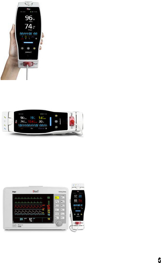
Functionality of the Radical-7
The Radical-7 provides the functionality of three instruments in one:
Handheld Pulse CO-Oximeter
The Radical-7 is a fully featured Handheld.
The Handheld contains the majority of the device features. All
measurements and instrument status datum are displayed on the
touchscreen. All user input is performed through the touchscreen and
control buttons. The sensor cable connector is located on the
Handheld.
Standalone Pulse Oximeter
The Radical-7 is a fully featured Standalone Pulse-Oximeter, and Acoustic Monitor.
The Handheld snaps into the Docking Station to
provide a fully featured standalone monitor. The
Docking Station connects to AC power for
standalone operation or charging of the
Handheld. An optional Docking Station battery is
available. The Standalone features Nurse Call,
analog output, and serial output.
Monitor Interface
The Radical-7 interfaces to the SpO2 input module of multi-parameter patient monitors to
upgrade conventional pulse oximetry technology on the multi-parameter monitor to Masimo
SET technology.
Utilizing a SatShare cable, the standalone
Radical-7 also interfaces with the SpO2 input of a
validated multi-parameter patient monitor,
instantly upgrading the conventional pulse
oximetry to Masimo SET pulse oximetry. The
SatShare cable attaches to the back of the Radical
Docking Station, and SatShare cables are
available to interface with most multi-parameter
patient monitors.
Radical-7 Chapter 2: Radical-7 Descriptions
www.masimo.com 35 Masimo
Handheld
All user input and displays are controlled by this component. The patient cable connects into
the connector on the Handheld instrument. The Handheld is battery powered and can be
used either as a transport monitor or as a Handheld Pulse CO-Oximeter for spot checks.
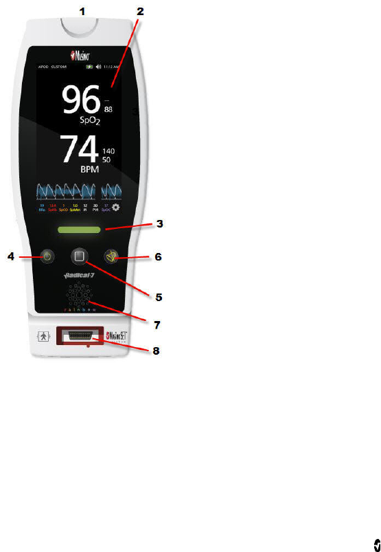
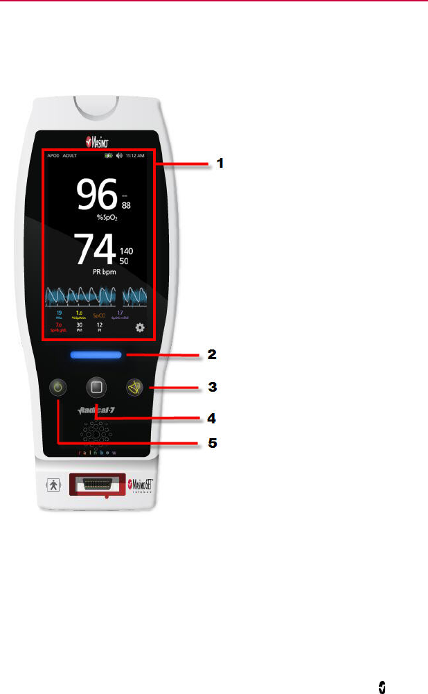
Handheld Front Panel
The following figure numbers and corresponding table describes the hardware features of the
Radical-7.
1
Handheld Release button
Press down the Handheld Release Button to pull
the Handheld off the Docking Station.
2
Touchscreen Display
The Touchscreen Display refers to the interactive
area on the Handheld. There are different Display
Views that can appear in this area. For more about
using the Touchscreen and Display Views, see
Changing the Size of Parameter Values on page
50.
3
Profile button
The Profile button provides instant access to the
Profile Screen. See Chapter 5: Profiles on page 93.
4
Power button
To turn on the Radical-7, press the Power button.
To turn off, press and hold the button for more
than 2 seconds.
5
Home button
The Home button provides instant access to the
Display View screen.
6
Alarm Silence Button
The Alarm Silence button temporarily silences
alarms. See Silencing the Alarms on page 99.
7
Speaker
The speaker indicates audio alarms. Care should
be taken not to cover the speaker and muffle the
audible alarm volume.
8
Patient Cable Connector
Connect a patient cable or a direct cable sensor
into the Radical-7
Radical-7 Chapter 2: Radical-7 Descriptions
www.masimo.com 36 Masimo
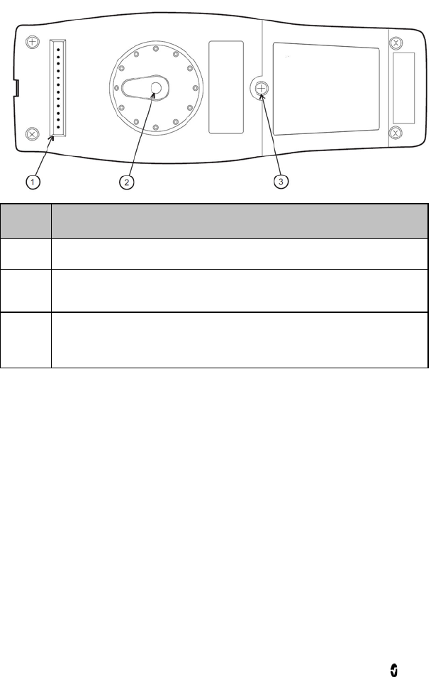
Handheld Back Panel
The Handheld back panel features the connection to the Docking Station, an accessory mount
for the pole clamp accessory, and access to the Handheld battery pack.
Item Description
1 The Handheld interfaces with the Docking Station through this connector.
2 The optional Pole Clamp accessory attaches to this holder. See the directions
for use of the Pole Clamp accessory for attachment instructions.
3 The Handheld is powered by a lithium ion battery located in this compartment.
For battery care and replacement, see Battery Operation and Maintenance on
page 131.

Radical-7 Chapter 2: Radical-7 Descriptions
www.masimo.com 37 Masimo
Standalone
When the Handheld is placed into the Docking Station, they become a full-featured
standalone system. In this manual, when the Handheld and the Docking Station are
connected, they are referred to Standalone. The Standalone acts as a battery charger for the
Handheld and has AC power connection capabilities. If the AC power from the wall outlet is
temporarily interrupted, then the battery in the Handheld allows for continuous operation.
The Standalone can also interface with serial instruments, Nurse Call or analog output
instruments, and multi-parameter patient monitors through a SatShare cable.
There are several models of compatible Docking Stations available: RDS-1, RDS-2, and RDS-3.
The RDS-1 and RDS-3 are optionally available with SafetyNet capability. The following table
lists which features are available for each model of Docking Station.
Docking Station Features RDS-1 RDS-2 RDS-3
AC Power Input
SatShare Interface
Serial RS-232 interface
Nurse Call/Analog Output interface
10-Hour Extended Battery
Automatic Display Rotation Support (Gravity
Detector)
Docking Station Battery Charging indicator
Handheld Battery Charging indicator
Visual Alarm indicator
AC Power indicator
Docking indicator
Radical-7 Chapter 2: Radical-7 Descriptions
www.masimo.com 38 Masimo
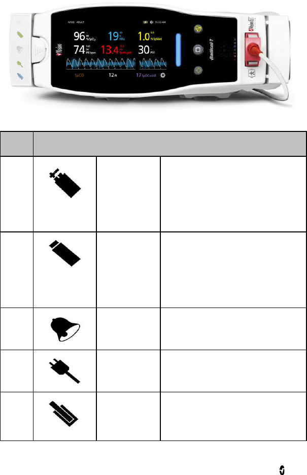
Standalone Front Panel
The following figure and corresponding text review the features of the Radical-7 Standalone.
Note that when the Standalone is turned on, all indicator LEDs initially turn on and off at
start up.
Item Description
1
Docking Station
Battery Charging
Indicator
The Docking Station Battery Charging
indicator is illuminated when the Docking
Station battery is charging. The indicator
blinks just prior to charging. The Charging
Indicator does not illuminate when the
battery is fully charged or when the
battery is not present.
2
Handheld
Battery Charging
indicator
The Handheld Battery Charging indicator
is illuminated when the Handheld battery
is charging. The indicator blinks just prior
to charging. The Charging Indicator does
not illuminate when the battery is fully
charged or when the battery is not
present.
3
Visual Alarm
Indicator The Visual Alarm indicator is illuminated
when an alarm condition is active and the
Alarm Status Indicator is shown.
4
AC Power
Indicator The AC Power indicator is illuminated
when the Radical-7 Docking Station is
plugged into AC line power.
5
Docking
Indicator The Docking indicator is illuminated
when the Handheld instrument is turned
on and is properly interfaced to a Docking
Station.

Radical-7 Chapter 2: Radical-7 Descriptions
www.masimo.com 39 Masimo
Standalone Back Panel
The following figure and corresponding text review the features of the Radical-7 Standalone.
Item Connector Description
1 Serial Output
connector Use the Serial Output connector with a ferrite bead
installed to connect a serial instrument, including a
serial printer, a monitoring system or PC to the Radical-
7.
The data is provided in standard RS-232C format. All
external instrument connections to the Serial Output
connector must be IEC-60950 compliant.
2 Analog
Output/Nurse Call
connector
Use the Analog Output connector with a ferrite bead
installed to interface with an analog output instrument,
such as a chart recorder or Nurse Call system. All external
instrument connections to the Analog Output/Nurse Call
connector must be IEC-60950 compliant.
See Serial Interface Specifications on page 122.
3 SatShare Cable
connector Use the SatShare Cable connector to connect a SatShare
cable to the SpO2 input connector of a multi-parameter
patient monitor. All external instrument connections to
the SatShare Cable Connector must be IEC-60601-1-1
compliant. SatShare cables are available to interface
with most major multi-parameter patient monitors.
Check the label on the SatShare cable and the SatShare
Directions for Use to ensure that the correct cable is used
for each type of patient monitor.
Visit www.masimo.com for the latest SatShare cables
and validated instruments.
Radical-7 Chapter 2: Radical-7 Descriptions
www.masimo.com 40 Masimo
Item Connector Description
4 Power Entry module
The Power Entry module contains the input connector for
AC power and two fuses. The AC input provides power to
the system from the AC line. Always connect the
Radical-7 to the mains power for continuous operation
and/ or battery recharging. Note: Use the power cord as
the means to disconnect the instrument from the mains
power supply.
5 Equipotential
Ground connector Use the Equipotential Ground connector for grounding.
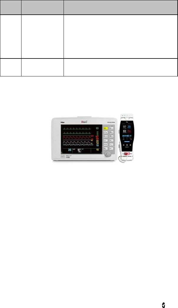
Monitor Interface With SatShare
The Radical-7 has a unique SatShare interface that links to most existing multi-parameter
patient monitors through a SatShare cable.
• Upgrades any approved and validated monitor to Masimo SET performance by
using the calculated SpO2 and pulse rate determined by Radical-7 to simulate an
ideal plethysmograph waveform, which is sent to the validated multi-parameter
patient monitor.
• Connects into the SpO2 patient cable or SpO2 input connector of the
multi-parameter patient monitor.
See Setting Up and Using SatShare on page 44.

www.masimo.com 41 Masimo
Chapter 3: Setup
The following chapter contains information about setting up the Radical-7 before use.
Unpacking and Inspection
To unpack and inspect the device
1. Remove the instrument from the shipping carton and examine it for signs of
shipping damage.
2. Check all materials against the packing list. Save all packing materials, invoice
and bill of lading. These may be required to process a claim with the carrier.
3. If anything is missing or damaged, contact the Technical Service Department. See
Return Procedure on page 136.
Docking Station Power Requirements
• Always use a hospital-grade, AC power cable to connect the Docking Station to an
AC power source.
• Do not connect the Docking Station to an AC outlet that is controlled by a switch
because the power to the Docking Station may be inadvertently switched off.
• Verify the AC power voltage and line frequency before use.
• Verify that the power source can provide an adequate power rating as indicated on
the rear panel of the Docking Station.
• The Radical-7 is designed to operate on 100 to 240VAC, 47-63 Hz.
• The Radical-7 is rated at 55 VA max.
• Connect a hospital-grade power cable (IEC-320 connector type at the instrument)
to the Power Entry module on the Docking Station.
• Connect the power cable to an AC power source.
• Ensure that the instrument is adequately powered by verifying that the AC power
indicator on the Docking Station is illuminated.
See Safety Information, Warnings, and Cautions on page 11.
Setting Up the Docking Station
Place the Docking Station on a stable hard flat surface near the patient. Always place the
Radical-7 on a dry surface. Maintain a minimum of 3 cm (1 inch) free space around the
Radical-7. Make sure that the Radical-7 speaker is not covered to avoid a muffled alarm
sound.
The Radical-7 Handheld, Docking Station or Standalone should not be operated outside the
environmental conditions listed in the specifications section Environmental on page 118.

Radical-7 Chapter 3: Setup
www.masimo.com 42 Masimo
Initial Battery Charging
Before use, the Radical-7 Handheld battery and the Docking Station battery must be charged
completely. See Electrical Safety Information, Warnings, and Cautions on page 18.
To charge the Handheld and Docking Station for the first time
1. Attach the Handheld to the Docking Station.
2. Plug in the AC power cord to power entry module. Make sure it is securely plugged
in.
3. Plug the AC power cord into an AC power source.
4. Verify that the batteries are charging.
• The Battery Charging indicators on the Docking Station flash prior to
charging and remain illuminated while the batteries are charging.
See Standalone Front Panel on page 38 and Battery Operation and Maintenance on page
131.
Setting Up for Philips, Agilent, or HP VueLink
To set up for use with VueLink compatible monitors (Philips, Agilent, or HP)
1. On the Radical-7, on the device output screen, for the serial option, select Hp
VueLink.
2. Connect one end of the VueLink cable to the Serial Output connector on the
Docking Station.
3. Connect the other end of the VueLink cable to the VueLink module and insert the
module into the VueLink compatible monitor rack.
The SpO2 and pulse rate values appear on the VueLink compatible monitor.
4. In order for the plethysmographic waveform to be displayed on the VueLink
compatible monitor, and for the VueLink monitor to convey alarm conditions
measured by the Radical-7, the VueLink compatible monitor must be properly
configured.
5. See instructions for use provided with the VueLink compatible monitor and the
VueLink module. See Device Related Safety Information, Warnings, and Cautions
on page 14 and Serial Interface Specifications on page 122.

Radical-7 Chapter 3: Setup
www.masimo.com 43 Masimo
Setting Up for SpaceLabs Flexport
To set up for use with SpaceLabs Flexport
1. On the Radical-7, on the device output screen, for the serial option, select
SpaceLabs Flexport.
2. Connect one end of the Spacelabs Flexport cable to the Serial Output connector on
the Docking Station.
3. Connect the other end of the Spacelabs Flexport cable to the Spacelabs Universal
Flexport connector.
The SpO2 and pulse rate values appear on the Spacelabs screen.
4. In order for the plethysmographic waveform to be displayed on the Spacelabs
screen, and for the Spacelabs monitor to convey alarm conditions measured by the
Radical-7, the Spacelabs monitor must be properly configured.
5. See instructions for use provided with the Spacelabs monitor. See Device Related
Safety Information, Warnings, and Cautions on page 14 and Serial Interface
Specifications on page 122.

Radical-7 Chapter 3: Setup
www.masimo.com 44 Masimo
Setting Up and Using SatShare
Parameter values from the Radical-7 can be displayed on a multi-parameter monitor through
the SatShare feature. The SatShare feature provides an ideal, simulated plethysmographic
waveform that corresponds to the parameter values determined the by Radical-7. This
waveform may be used to display these values on multi-parameter monitors through the
multi-parameter oximetry sensor or input connector.
It is recommended that the Radical-7 be positioned near the multi-parameter monitor, with
the Radical-7 screen displaying the plethysmographic waveform and the parameter values.
Refer to the instructions for use provided with the multi-parameter monitor. See Device
Related Safety Information, Warnings, and Cautions on page 14.
To set up for use with SatShare interface
1. Select the SatShare cable that is appropriate for the multi-parameter monitor. For
the latest list of available SatShare cables and validated instruments, see
www.masimo.com.
2. Connect the labeled end of the SatShare cable to the SatShare Cable connector on
the Docking Station. See Standalone Back Panel on page 39. For a secure
connection, tighten the cable connector screws.
3. Connect the other end of the SatShare cable to one of the following:
• Sensor connector of the multi-parameter monitor cable
• Directly to the multi-parameter monitor
4. Verify that the Radical-7 recognizes the SatShare cable. If functional, the name of
the SatShare cable displays on the Radical-7 screen.
5. As appropriate, configure alarm limits on the multi-parameter monitor.
6. Set the averaging time for the multi-parameter monitor to its lowest setting (or
fastest response). The ideal waveform for the Radical-7 requires additional
averaging by the monitor. If the averaging time of the multi-parameter monitor is
not changed, the time to display physiological changes in saturation on the
monitor is increased with SatShare. However, the delay can be minimized by
reducing the averaging time on the multi-parameter monitor.
7. While in the SatShare mode, if there are any significant discrepancies between the
readings from Radical-7 and those on the monitor displaying the values obtained
from SatShare, the values reported by the Radical-7 are to be considered the
correct values.
8. It is possible to use the Radical-7 with SatShare while the Radical-7 is not
connected to AC power. However, in this configuration, battery run time is
reduced. See Battery Operation and Maintenance on page 131.
9. On the Radical-7, turn on the Satshare Numbers option. See Device Output on
page 80.
10. If displaying the simulated waveform is not desirable, it is recommended to turn
off the plethysmographic waveform display of the multi-parameter patient
monitor. See Serial Interface Specifications on page 122.
www.masimo.com 45 Masimo
Chapter 4: Operation
The following chapter contains information about using the Radical-7.
Using the Touchscreen and Buttons
1.
Display View
To access other screens,
touch a value on the Display
View. See About the Display
View on page 48.
2. Profiles button
To the access the Profiles
screen, press Profiles. See
Chapter 5: Profiles on page
93.
3. Alarm Silence button
To temporarily silence
audible alarms, press Alarm
Silence. See Silencing the
Alarms on page 99.
4. Home button
To return to the Display
View, press Home.
5. Power button
To turn on the Radical-7,
press the Power button. To
turn off, press and hold the
button for more than 2
seconds
Radical-7 Chapter 4: Operation
www.masimo.com 46 Masimo
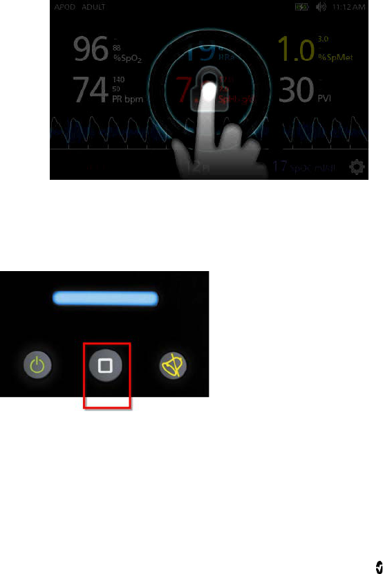
Using Screen Lock
When turned on, the Screen Lock feature may prevent unintentional interaction with Display
View.
Using the Screen Lock feature
1. When turned on, any interaction with the Display View triggers the Screen Lock
feature.
2. To bypass Screen Lock when it appears, press and hold the Lock icon until it
unlocks.
3. To turn on or turn off Screen Lock, see Access Control on page 76.
Using the Home Button
One option to return to Display View is by using the Home button.
To return to Display View using the Home button
• From any screen, press Home.
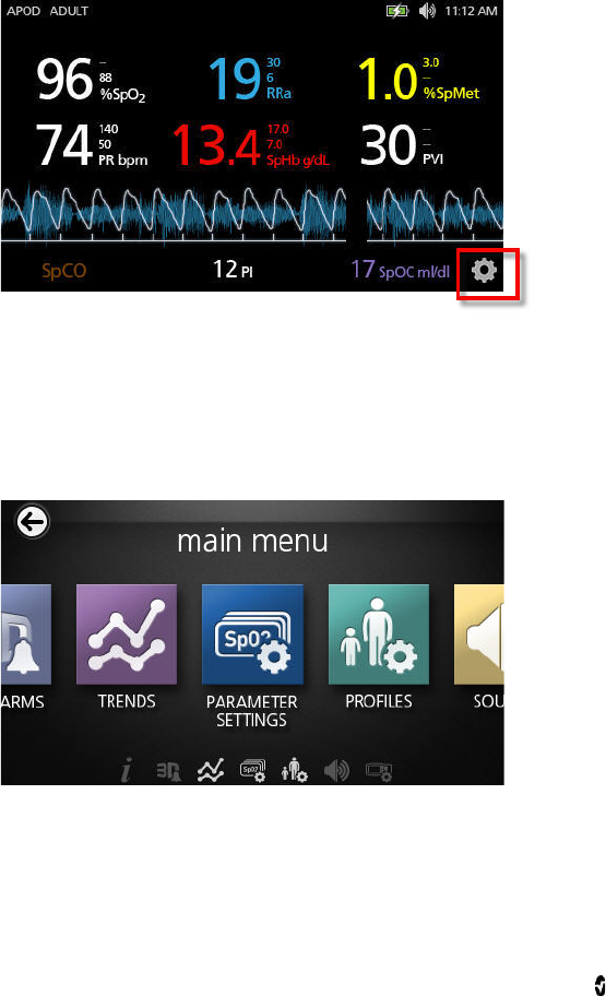
Radical-7 Chapter 4: Operation
www.masimo.com 47 Masimo
Navigating the Radical-7
Navigate the Radical-7 screens via the Display View or the Main Menu.
Display View
The following is the primary interactive screen that the user views.
To access the Main Menu screen
• Touch the gear icon at the lower right corner of the display.
Main Menu
The following is the Main Menu screen where users can access additional screens and
information. Users can swipe the screen left or right to pan the Menu Icons. Users can touch
the arrow icon to return to the Display View. See Accessing the Main Menu on page 57.
Display Timeout
When no user interaction occurs within 1 minute, the display times out and returns to the
Display View.
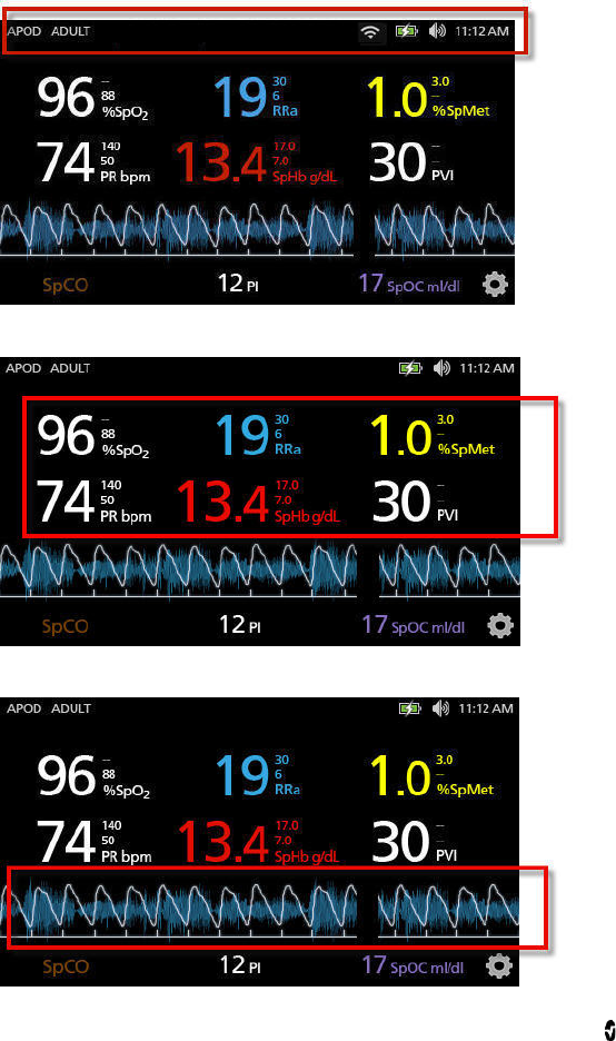
Radical-7 Chapter 4: Operation
www.masimo.com 48 Masimo
About the Display View
The Display View consists of different areas:
Status Bar. See About the Status Bar on page 49.
Parameter Display. See Changing the Size of Parameter Values on page 50.
Trend Field. See Waveform and Trend Views on page 52.
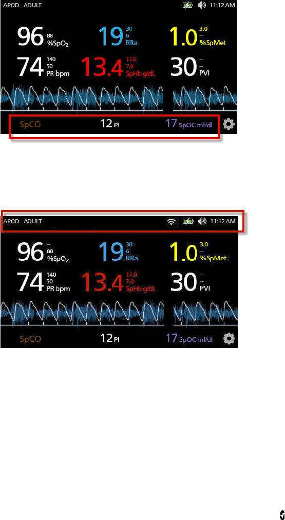
Radical-7 Chapter 4: Operation
www.masimo.com 49 Masimo
Small Parameter View. See Accessing the Main Menu on page 57.
About the Status Bar
The Status Bar is visible on the top portion of the Display View.
Status Bar
Access additional screens, more information, or toggle features by touching directly on any of
the following indicators in the Status Bar.
• Sensitivity Modes. See Sensitivity Modes Overview on page 55.
• Profiles. See Profiles Overview on page 93.
• Messages on page 104. (read only)
• WiFi on page 79.
• Battery on page 80.
• Sounds on page 74.
• Time settings. See Localization on page 78.
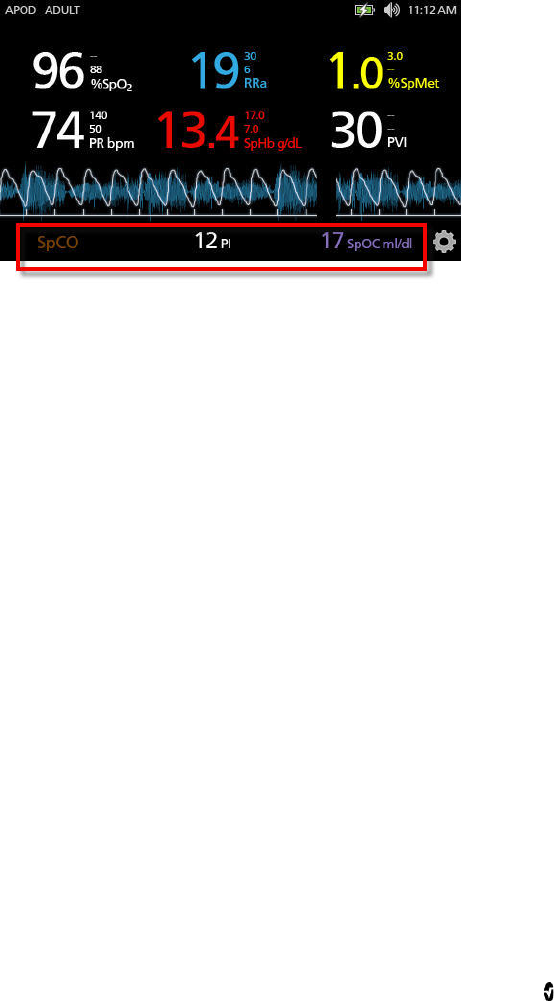
Radical-7 Chapter 4: Operation
www.masimo.com 50 Masimo
Changing the Size of Parameter Values
To change the size of parameter values on the Display View
1. On the Small Parameter view, touch and hold any one of the parameters, as shown
above.
2. When the parameter value dims, shakes, and grows in size, drag and drop that
parameter above the Trend Field.
3. The parameter value appears on the screen in a larger font. The device
automatically configures the screen for optimal display of the parameter values.
4. To remove parameter values from the larger font display, press and hold the larger
parameter value. Then drag and drop the parameter value back to the Small
Parameter view.
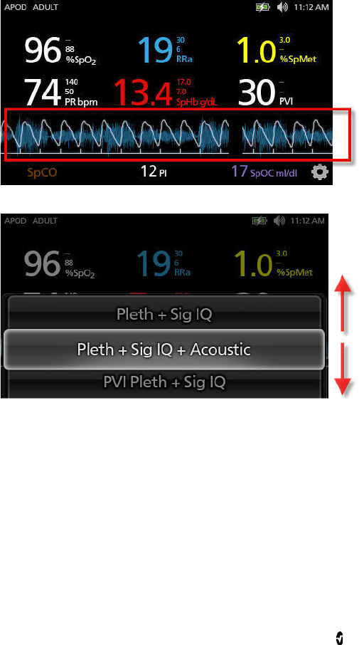
Radical-7 Chapter 4: Operation
www.masimo.com 51 Masimo
Trend Field
The Trend Field allows users to access various customizable views. See Trends on page 81.
To access trend, waveform, or customize the views on the Display View screen
1. Touch the Trend Field, as shown below.
2. The following screen appears.
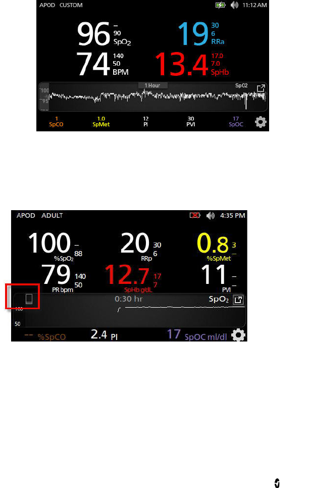
Radical-7 Chapter 4: Operation
www.masimo.com 52 Masimo
3. Swipe up or swipe down the available options.
4. Touch on the desired option.
5. The Trend Field displays trend data specific to the option that was selected.
Pulse Bar
The Pulse Bar is a visual indicator that conveys the detection of pulse and the Signal IQ (SIQ)
displayed on each individual pulsation. The height of the bars provides an assessment of the
confidence in the measurement displayed. See Signal IQ Indicators on page 53.
Waveform and Trend Views
The following section contain information about trends and waveforms available from the
Trend Field on the Display View screen. The following are examples of some of the views that
are available.
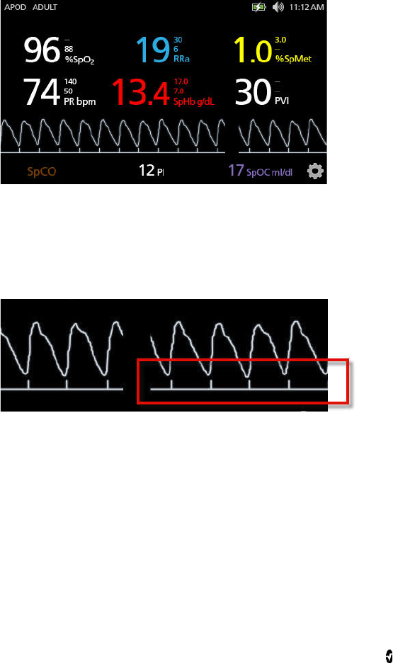
Radical-7 Chapter 4: Operation
www.masimo.com 53 Masimo
Pleth + Sig IQ View
Shows the parameter values on the top of the screen. The waveform is located below the
parameter values. The Small Parameter view is located along the bottom of the screen. This
view contains the Pleth Waveform with signal quality indications only.
Signal IQ Indicators
The Signal IQ (SIQ), displayed on each individual pulsation, is conveyed by vertical bars, as
shown below. The height of the bar provides an assessment of the confidence in the
measurement displayed.
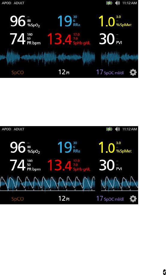
Radical-7 Chapter 4: Operation
www.masimo.com 54 Masimo
Acoustic Waveform View
Shows the parameter values on the top of the screen. The RRa waveform is located below the
parameter values. The Small Parameter view is located along the bottom of the screen.
Acoustic Respiratory Rate (RRa) must be available for this feature to be shown. This view
contains acoustic respiratory rate waveform only.
Pleth + Sig IQ + Acoustic View
Shows the parameter values on the top of the screen. The waveform is located below the
parameter values. The Small Parameter view is located along the bottom of the screen. This
view contains the Pleth waveform, signal quality indications, and acoustic waveform.
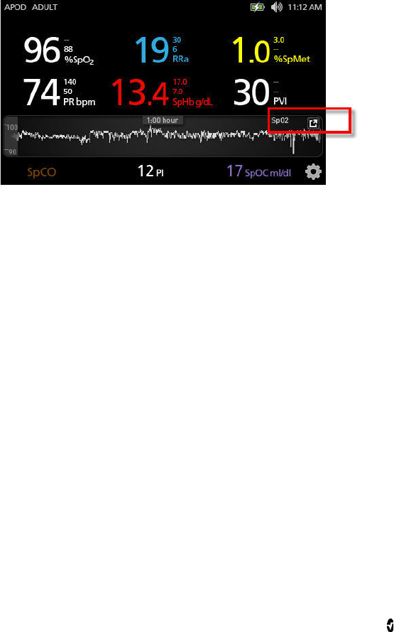
Radical-7 Chapter 4: Operation
www.masimo.com 55 Masimo
Parameter Quick Trend View
This view displays the quick trend of the selected parameter over an adjustable period of
time. The default is 1 hour. Enlarge the quick trend to the full trend view by touching the
expand icon of the waveform display.
With a pinch gesture, using two fingers, the user can zoom in and out of the quick trend data
within the Trend Field.
Sensitivity Modes Overview
Three sensitivity levels enable a clinician to tailor the response of the Radical-7 to the needs
of the particular patient situation. Access the menu by touching on the indicator in the upper
left corner of the Display View. The sensitivity levels are as follows:
• NORM (Normal Sensitivity)
NORM is the recommended sensitivity mode for patients who are experiencing
some compromise in blood flow or perfusion. It is advisable for care areas where
patients are observed frequently, such as an intensive care unit (ICU).
• APOD (Adaptive Probe Off Detection Sensitivity)
APOD is the recommended sensitivity mode where there is a high probability of
the sensor becoming detached. It is also the suggested mode for care areas where
patients are not visually monitored continuously. This mode delivers enhanced
protection against erroneous pulse rate and arterial oxygen saturation readings
when a sensor becomes inadvertently detached from a patient due to excessive
movement.
• MAX (Maximum Sensitivity)
MAX is recommended sensitivity mode for patients with low perfusion or when a
low perfusion message displays in APOD or NORM mode. MAX mode is not
recommended for care areas where patients are not monitored visually, such as
general wards. It is designed to interpret and display data at the measuring site
when the signal may be weak due to decreased perfusion. When a sensor becomes
detached from a patient, it will have compromised protection against erroneous
pulse rate and arterial saturation readings.
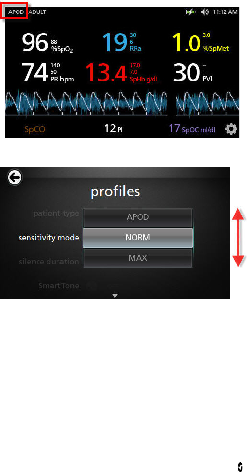
Radical-7 Chapter 4: Operation
www.masimo.com 56 Masimo
Changing Sensitivity Modes
There are two ways to change the sensitivity modes.
1. Press the indication on the top left of the Display View.
2. Alternatively, from the Main Menu, touch the Profiles icon. From the Profiles
screen, select the desired mode by scrolling up or down. Then select OK.
Note that the device will revert to APOD mode after a power cycle.
See Changing Profiles on page 94.
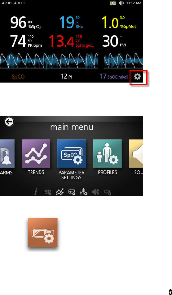
Radical-7 Chapter 4: Operation
www.masimo.com 57 Masimo
Accessing the Main Menu
To access Main Menu from the Display View, touch the gear icon on the bottom right corner of
the Small Parameter View.
Navigating the Main Menu
• From the Main Menu screen, touch the icons for any of the following screens:
Device Settings
See Device Settings on page 75.
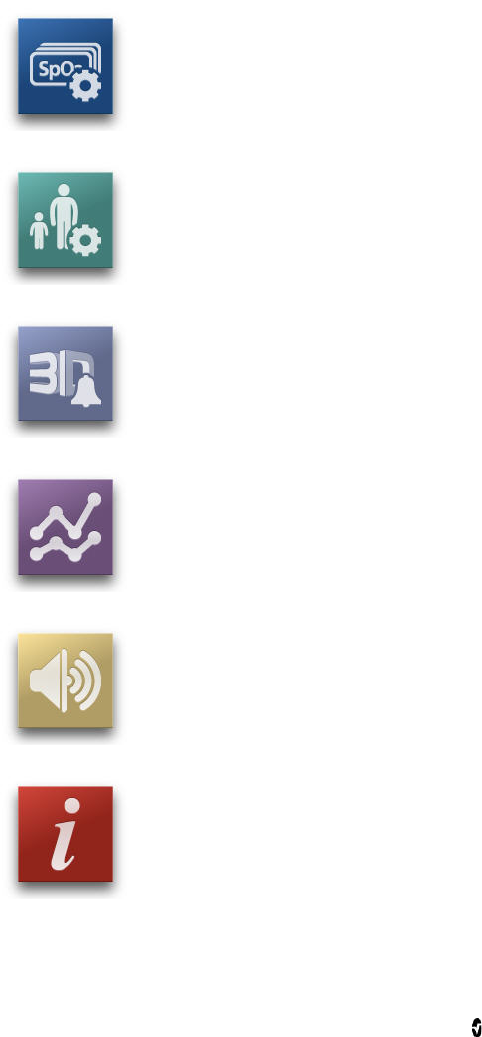
Radical-7 Chapter 4: Operation
www.masimo.com 58 Masimo
Parameter Settings
See Parameter Settings on page 59.
Profiles
See Changing Profiles on page 94.
3D Alarms
See 3D Alarms on page 102.
Trends
See Trends on page 81 and Trend Field on page 51.
Sound
See Sounds on page 74.
About
See About on page 91.
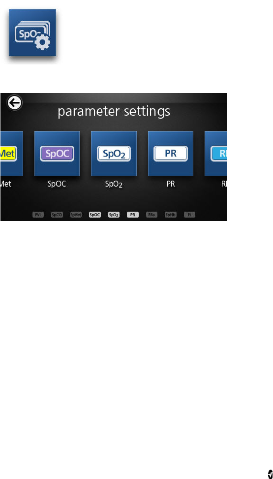
Radical-7 Chapter 4: Operation
www.masimo.com 59 Masimo
Parameter Settings
The following is an example of the Parameter Settings screen. Only parameters that have
been loaded onto the system will be visible.
To access any of the available parameter setting screens
1. From the Parameter Settings screen, to access the desired parameter, flick the
on-screen icons left or right.
2. Touch the icon of the desired parameter. For details, see any of the following
sections.
SpO2 Settings on page 62.
SpHb Settings on page 63.
PVI Settings on page 70.
PR Settings on page 65.
Perfusion Index (PI) Settings on page 66.
SpCO Settings on page 71.
SpMet Settings on page 72.
SpOC Alarms on page 73.
Respiration Rate (RR) on page 67.
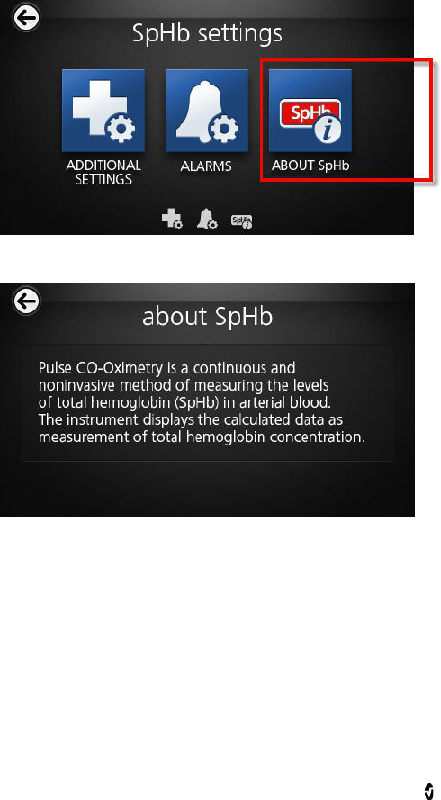
Radical-7 Chapter 4: Operation
www.masimo.com 60 Masimo
About Parameter Information
Additional information about each parameter is available.
To access additional information about parameters
1. From the parameter settings screen, touch the About icon. The following is an
example for SpHb.
2. An About screen appears for the selected parameter.
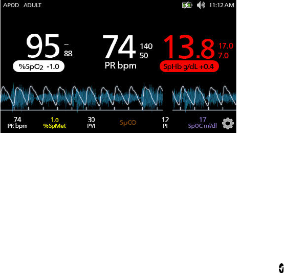
Radical-7 Chapter 4: Operation
www.masimo.com 61 Masimo
In Vivo Adjustment Overview
The In Vivo Adjustment feature lets clinicians manually adjust one or more clinical
parameters to match that of a corresponding laboratory reference for continuous trending. To
remind clinicians that the feature is active, an offset value displays alongside the adjusted
parameter value.
When the In Vivo Adjustment is set to On, the feature is active (turned on) and a positive or a
negative offset value appears, as shown in the following illustration.
The In Vivo offset is set to zero for any of the following:
• Cable or sensor is disconnect from instrument.
• Sensor goes off patient causing a sensor initialization to occur.
• Eight hours has elapsed since the In Vivo value was activated.
• Restore of factory defaults.
• The user turns off In Vivo.
Offset value
The offset value appears and indicates that In Vivo Adjustment is active. A positive value
means that the value is increased (according to a laboratory reference value as entered by a
clinician) and a negative value means the value is decreased (according to a laboratory
reference value as entered by a clinician).
In the example below, the SpO2 value is offset (highlighted) by -1.0 and SpHb is offset by
+0.4.
The In Vivo Adjustment feature can be set to On or Off. the factory default setting is Off. If set
to On, the parameter value is adjusted and an offset value appears. The offset value is set by
the user.
The feature applies to any of the following parameters:
In Vivo for SpO2 on page 63.
In Vivo for SpHb on page 65.
In Vivo for SpCO on page 72.
In Vivo for SpMet on page 73.

Radical-7 Chapter 4: Operation
www.masimo.com 62 Masimo
SpO2 Settings
Access any of the following options:
Alarms for SpO2.
Additional Settings for SpO2 on page 63.
About Parameter Information on page 60.
Alarms for SpO2
From the Alarms screen, change any of the following options:
Options Description Factory Default
Settings Configurable Options
High Limit High Limit is the upper
threshold that triggers an
alarm. Off
2% to 99% in steps of
1%, or Off
When set to Off, alarm
is disabled
Low Limit Low Limit is the lower
threshold that triggers an
alarm. 88% 1% to 98% in steps of
1%
Rapid Desat
Sets the Rapid Desat limit
threshold to the selected
amount below the Low
Alarm Limit. When SpO2
value falls below rapid desat
limit the audio and visual
alarm are immediately
triggered without respect to
the alarm delay.
-10% Off, -5%, or -10%
Alarm Delay When an alarm condition is
met, this feature delays the
audible part of an alarm. 5 seconds 0, 5, 10, or 15 seconds
Adaptive
Threshold
Alarm (ATA)
ATA establishes
patient-specific limit
thresholds based upon the
baseline value of the
parameter.
See Adaptive Threshold
Alarm (ATA) Feature on
page 101.
Off Off or On

Radical-7 Chapter 4: Operation
www.masimo.com 63 Masimo
Additional Settings for SpO2
From the Additional Settings screen, change any of the following options:
Options Description Factory Default
Settings User Configurable
Settings
Averaging Time The length of time over which the
system calculates the average of
all data points.
8 seconds 2-4, 4-6, 8, 10, 12,
14, or 16 seconds
FastSat See FastSat Overview on page
63. Off On or Off
FastSat Overview
FastSat enables rapid tracking of arterial oxygen saturation changes. Arterial oxygen
saturation data is averaged using pulse oximeter averaging algorithms to smooth the trend.
When the Radical-7 is set to FastSat On, the averaging algorithm evaluates all the saturation
values providing an averaged saturation value that is a better representation of the patient’s
current oxygenation status. With FastSat, the averaging time is dependent on the input
signal.
In Vivo for SpO2
From the In Vivo screen, change any of the following options:
Options Description Factory Default
Settings User Configurable
Settings
Enabled See In Vivo Adjustment
Overview on page 61. Off On or Off
Offset Amount See In Vivo Adjustment
Overview on page 61. 0 when turned
on Adjust difference of ±
6%, in steps of 0.1%
SpHb Settings
From the SpHb Settings screen, access any of the following screens:
SpHb Alarms on page 64.
Additional Settings for SpHb on page 64.
About Parameter Information on page 60.

Radical-7 Chapter 4: Operation
www.masimo.com 64 Masimo
SpHb Alarms
From the Alarms screen, change any of the following options:
Options Description Factory Default
Settings User Configurable Settings
High Limit The High Limit is
upper threshold
that triggers an
alarm.
17.0 g/dL
(11.0 mmol/L)
2.0 g/dL to 24.5 g/dL in steps
of 0.1 g/dL, or Off
(2.0 mmol/L to 15.0 mmol/L
in steps of 0.1 mmol/L, or Off)
When SpHb Precision is set to
1.0, the values are rounded
down.
When set to Off, alarm is
disabled.
Low Limit The Low Limit is
lower threshold
that triggers an
alarm.
7.0 g/dL
(4.0 mmol/L)
Off, or 1.0 g/dL to 23.5 g/dL in
steps of 0.1 g/dL
(Off, or 1.0 mmol/L to 14.5
mmol/L, in steps of 0.1
mmol/L)
When SpHb Precision is set to
1.0, values are rounded down.
When set to Off, alarm is
disabled.
Additional Settings for SpHb
From the Additional Settings screen, change any of the following options:
Options Description Factory Default
Settings User Configurable
Settings
Averaging Time The length of time over
which the system
calculates the average of all
data points.
Medium Short, Medium, or Long
Calibration Provides an arterial or
venous value that displays
on the main screen.
Venous Arterial or Venous
Precision Allows the user to set the
decimal for SpHb. 0.1 0.1, 0.5, or 1.0 (whole
numbers)

Radical-7 Chapter 4: Operation
www.masimo.com 65 Masimo
Unit of Measure
Displays total hemoglobin
(SpHb) as g/dL (grams per
deciliter) or mmol/L
(milimoles per liter).
g/dL mmol/L or g/dL
In Vivo for SpHb
From the In Vivo screen, change any of the following options:
Options Description Factory Default
Settings User Configurable
Settings
In Vivo
Calibration See In Vivo Adjustment
Overview on page 61. Off On or Off
In Vivo
Calibration
Offset
See In Vivo Adjustment
Overview on page 61. 0 ± 3 g/dL in steps of ±
0.1 g/dL
PR Settings
From the PR Settings screen, change any of the following options:
PR Alarms on page 65.
About Parameter Information on page 60.
PR Alarms
From the PR Alarms screen, change any of the following options:
Options Description Factory Default
Settings Options
High Limit The High Limit is upper
threshold that triggers an
alarm.
140 bpm
35 bpm to 235 bpm, in
steps of 5 bpm
Low Limit The Low Limit is lower
threshold that triggers an
alarm.
50 bpm 30 bpm to 230 bpm, in
steps of 5 bpm

Radical-7 Chapter 4: Operation
www.masimo.com 66 Masimo
Perfusion Index (PI) Settings
From the PI Settings screen, access any of the following screens:
PI Alarms on page 66.
Additional Settings for PI on page 66.
About Parameter Information on page 60.
PI Alarms
From the Alarms screen, change any of the following options:
Options Description Factory
Default
Settings
User Configurable Settings
High Limit The High Limit is upper
threshold that triggers an
alarm.
Off Step size:
0.04 to 0.09 in steps of
0.01
0.10 to 0.90 in steps of
0.10
1 to 19 in steps of 1, or Off
Low Limit The Low Limit is lower
threshold that triggers an
alarm.
Off Step size:
Off, or 0.03 to 0.09 in
steps of 0.01
0.10 to 0.90 in steps of
0.10
1 to 18 in steps of 1
Additional Settings for PI
From the Additional Settings screen, change any of the following options:
Options Description Factory
Default
Settings
User Configurable
Settings
Averaging
Time The length of time over which
the system calculates the
average of all data points.
Long Short or Long
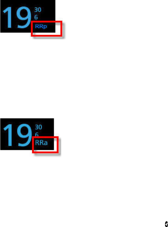
Radical-7 Chapter 4: Operation
www.masimo.com 67 Masimo
Respiration Rate (RR)
The Radical-7 can determine respiration rate (RR) either by the acoustic signal (RRa) or by
the plethysmographic waveform (RRp).
RRp Settings
When using a pulse oximetry or pulse CO-Oximetry sensor with the Radical-7, respiration rate
can be determined by the plethysmographic waveform (RRp). This method measures a
patient's respiratory rate based on plethysmographic amplitude changes that correspond to
the respiratory cycle. When using a pulse oximetry or pulse CO-Oximetry sensor, RRp alarms
and RRp settings are active and the Display View conveys respiratory rate as RRp, as shown
below.
Note that the Radical-7 can monitor RRa or RRp but not both simultaneously. RRp is active
under the following conditions:
• RRp is installed on the Radical-7.
• Dual Rainbow cable is disconnected.
• Pulse oximetry or pulse CO-Oximetry sensor is connected.
• Acoustic sensor is not connected.
When using an acoustic sensor, respiration rate (RR) is determined by the acoustic (RRa)
signal. See rainbow Acoustic Monitoring (RAM) Technology on page 29. When the
respiratory rate is determined by the acoustic signal, the Display View conveys respiratory
rate as RRa, as shown below.
From the RR Settings screen, access any of the following screens:
RRp Alarms on page 67.
Additional Settings for RRp on page 68.
RRp Alarms
From the Alarms screen, change any of the following options:

Radical-7 Chapter 4: Operation
www.masimo.com 68 Masimo
Options Description Factory Default Configurable Options
High Limit The High Limit is
upper threshold that
triggers an alarm.
30 breaths per
minute 6 breaths per minute to 69
breaths per minute, or Off
Low Limit The Low Limit is lower
threshold that
triggers an alarm.
6 breaths per
minute 5 breaths per minute to 68
breaths per minute, or Off
Alarm Delay When an alarm
condition is met, this
feature delays the
audible part of an
alarm.
30 second 0, 10, 15, 30, 60 seconds
Additional Settings for RRp
From the Additional Settings screen, change any of the following options:
Options Description Factory Default
Settings User Configurable Settings
Averaging
Time The length of time
over which the system
calculates the average
of all data points.
Slow No, Fast, Medium, Slow,
Trending
Freshness The duration of time
that, during
interference, the
system displays the
last valid reading.
5 minutes 0, 1, 5, 10, 15 minutes

Radical-7 Chapter 4: Operation
www.masimo.com 69 Masimo
RRa Settings
RRa is active under the following conditions:
• RRa is installed on the Radical-7.
• Dual Rainbow cable is connected.
• Acoustic sensor is connected.
From the RR Settings screen, access any of the following screens:
RRa Alarms on page 69.
Additional Settings for RRa on page 70.
About Parameter Information on page 60.
RRa Alarms
From the Alarms screen, change any of the following options:
Options Description Factory
Default
Settings
Configurable Options
High Limit The High Limit is upper
threshold that triggers
an alarm.
30 breaths
per minute 6 to 69 breaths per minute in
steps of 1 breaths per minute,
or Off
Low Limit The Low Limit is lower
threshold that triggers
an alarm.
6 breaths per
minute 5 to 68 breaths per minute in
steps of 1 breaths per minute
Respiratory
Pause The duration of time
that triggers an alarm if
no breaths are
detected.
30 seconds 20, 25, 30, 35, 40, or 15
seconds
Alarm Delay When a High or Low
alarm condition occurs,
this feature delays the
audible part of an
alarm.
30 seconds 60, 0, 10, 15, or 30 seconds

Radical-7 Chapter 4: Operation
www.masimo.com 70 Masimo
Additional Settings for RRa
From the Additional Settings screen, change any of the following options:
Options Description Factory
Default
Settings
User Configurable Settings
Averaging Time The length of time
over which the system
calculates the average
of all data points.
Slow Trending, No, Fast, Medium, or
Slow
Freshness The duration of time
that, during
interference, the
system displays the
last valid reading.
5 minutes 10, 15, 0, 1, or 5 minutes
PVI Settings
From the PVI Settings screen, access any of the following options:
PVI Alarms on page 70.
Additional Settings for PVI on page 71.
About Parameter Information on page 60
PVI Alarms
From the Additional Settings screen, change any of the following options:
Options Description Factory
Default
Settings
User Configurable Settings
High Limit The High Limit is upper
threshold that triggers an
alarm.
Off 2 to 99, in steps of 1, or Off
When set to Off, alarms are
disabled.
Low Limit The Low Limit is lower
threshold that triggers an
alarm.
Off Off, 1 to 98 in steps of 1
When set to Off, alarms are
disabled.

Radical-7 Chapter 4: Operation
www.masimo.com 71 Masimo
Additional Settings for PVI
From the Additional Settings screen, change any of the following options:
Options Description Factory
Default
Settings
User Configurable Settings
Averaging
Time The length of time
over which the system
calculates the average
of all data points.
Long Short or Long
SpCO Settings
From the SpCO Settings screen, access the following screens:
SpCO Alarms on page 71.
About Parameter Information on page 60.
SpCO Alarms
From the SpCO Settings screen, access the following screens:
Options Description Factory
Default
Settings
User Configurable Settings
High Limit The High Limit is the upper
threshold that triggers an
alarm.
10 2% to 98%, in steps of 1%, or
Off
When set to Off, alarm is
disabled
Low Limit The Low Limit is the lower
threshold that triggers an
alarm.
Off Off, 1% to 97%, in steps of 1%
When set to Off, alarm is
disabled

Radical-7 Chapter 4: Operation
www.masimo.com 72 Masimo
In Vivo for SpCO
From the In Vivo screen, access the following screens:
Options Description Factory
Default
Settings
User Configurable Settings
Enabled See In Vivo Adjustment
Overview on page 61. Off On or Off
Offset Amount See In Vivo Adjustment
Overview on page 61. 0 ± 9% in steps of 0.1%
SpMet Settings
From the SpMet Settings screen, access the following screens:
SpMet Alarms on page 72.
About Parameter Information on page 60.
SpMet Alarms
From the Alarms screen, change any of the following options:
Options Description Factory
Default
Settings
User Configurable Settings
High Limit The High Alarm Limit
is upper threshold
that triggers an alarm.
3.0 1% to 2% in steps of 0.1%
2.5% to 99.5% in steps of 0.5%, or
Off
Low Limit The Low Alarm Limit
is lower threshold that
triggers an alarm.
Off Off, 0.1% to 2.0% in steps of 0.1%
2.5% to 99%, in steps of 0.5%

Radical-7 Chapter 4: Operation
www.masimo.com 73 Masimo
In Vivo for SpMet
From the In Vivo screen, access the following screens:
Options Description Factory
Default
Settings
User Configurable Settings
Enabled Match the corresponding
laboratory reference for
continuous trending.
Off On or Off
Offset Amount Helps offset individual
patient bias that is expected
when comparing a
noninvasive measurement
to a laboratory reference.
0 ±3% in steps of 0.1%
SpOC Settings
From the SpOC Settings screen, access the following screens:
SpOC Alarms on page 73.
About Parameter Information on page 60.
SpOC Alarms
From the SpOC Alarms screen, access the following screens:
Options Description Factory
Default
Settings
User Configurable Settings
High Limit The High Limit is the upper
threshold that triggers an
alarm.
Off 2% to 34% in steps of 1%, or
Off
Low Limit The Low Limit is the lower
threshold that triggers an
alarm.
Off Off, or 1% to 33% in steps of
1%
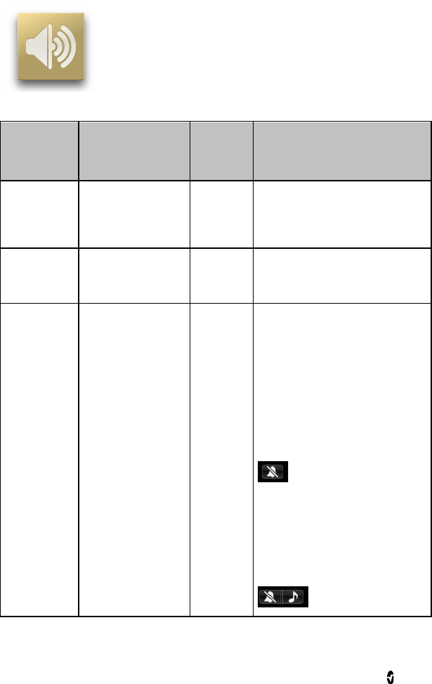
Radical-7 Chapter 4: Operation
www.masimo.com 74 Masimo
Sounds
From the Sounds screen, change any of the following options:
Options Description Factory
Default
Settings
User Configurable Settings
Alarm Volume Sets the alarm
volume and provides
a sample of the alarm
volume.
Level 4 Level 1 to 4
Pulse Tone
Volume Sets the volume of
the tone that conveys
the pulse rate.
Level 3 Off, Level 1 to 4
Silence
Duration Length of time that
the audible alarm
remains muted.
120
seconds 30, 60, 90, or 120 seconds
If All Mute is set to On (see Access
Control on page 76), then the
following additional settings
become available:
All Mute
If selected, then no alarms will
sound. Only visual elements are
enabled. The following icon appears
on the Display View.
All Mute with Reminder
If selected, then no alarms will
sound. Only visual elements are
enabled A tone sounds every 3
minutes as a reminder. The
following icon appears on the
Display View.
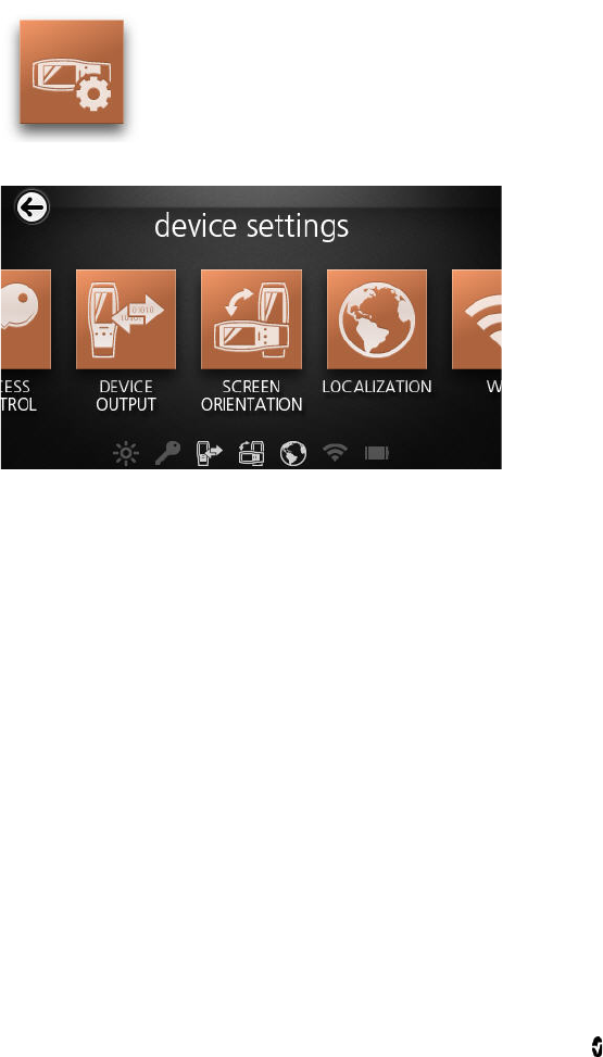
Radical-7 Chapter 4: Operation
www.masimo.com 75 Masimo
Device Settings
The following is an example of the Device Settings screen.
From the Device Settings screen, access any of the following options:
Screen Orientation on page 79.
Localization on page 78.
WiFi on page 79.
Battery on page 80.
Brightness on page 80.
Access Control on page 76.
Device Output on page 80.
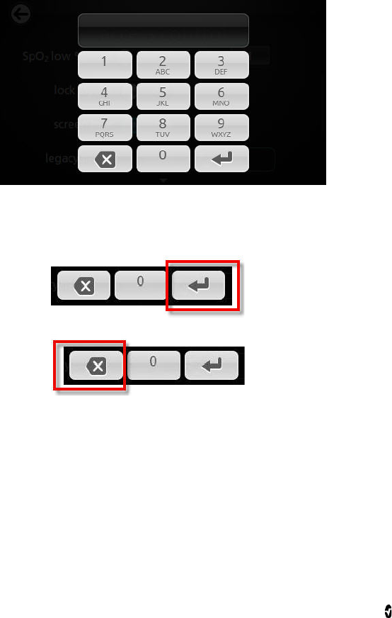
Radical-7 Chapter 4: Operation
www.masimo.com 76 Masimo
Access Control
The Access Control screen is protected by a Password screen.
Password Screen
Using the Password screen
1. On the Password screen, enter the following numbers: 6 2 7 4
No numbers will be displayed, only asterisks (****).
2. Touch Enter.
3. To undo numbers, touch Backspace.

Radical-7 Chapter 4: Operation
www.masimo.com 77 Masimo
Access Control Screen
From the Access Control screen, change any of the following options:
Options Description Factory
Default
Settings
User Configurable Settings
All Mute All patient alarm
conditions are
silenced. Only
system alarms will
be indicated by an
audible alarm.
Disabled Enabled or disabled
If enabled, All Mute and All Mute
with Reminder become available
settings from the Silence Duration
option on the Sounds screen. See
Sounds on page 74.
Lock Alarm
Volume When set to 3 or 4, 3
or 4 shows dimly lit
in the Alarm Volume
section of the
Alarms Menu screen
and cannot be
changed.
Off 3, 4, or Off
SpO2 Low %
Limit Threshold at which
SpO2 Low Alarm
Limit cannot be
reduced.
Off 1% to 98% in steps of 1, or Off
Lock Layout Prevents the user
from making
changes to the
parameter layout.
N/A On or Off
Screen Lock Prevents
unintentional
interaction with
Display View.
On On or Off
Legacy Mode Changes the Display
View from color to
monochrome.
Color Mono or Color
Save as Adult Saves
pre-configured
profiles for adult
patients.
N/A Press Save to load all device
configuration settings to adult
profile.
Save as Neo Saves
pre-configured
profiles for neonatal
patients
N/A Press Save to load all device
configuration settings to neonatal
profile.

Radical-7 Chapter 4: Operation
www.masimo.com 78 Masimo
Factory
Defaults Options are restored
to factory values. N/A Press Restore to return to factory
default values.
Localization
From the Localization screen, change any of the following options:
Options Description Factory Default
Settings User Configurable
Settings
Current Date Date N/A N/A
Current Time Time N/A N/A
Language Language in which the
screens display. English Choose from available
languages.
Time Zone Setting based on
Coordinated Universal Time
(UTC).
A (UTC+1hr) Choose local time zone
settings.
Date Format Set the format of the date
display on the Display View. MM/DD/YYYY MM/DD/YYYY
DD/MM/YYYY
Time Format Set the format of the time
display as it will be shown on
the Display View.
12 hour 24 hour or 12 hour
Line
Frequency Set to match regional power
line frequency to allow for
cancelation of noise
introduced by fluorescent
lights and other sources.
60 Hz 50 Hz or 60 Hz
Date Manually set the numerical
date if Auto Set Date/Time is
Off.
MM/DD/YYYY Choose month, date,
and year.
Time Manually set the hour and
minute, AM or PM, if Auto Set
Date/Time is Off.
12-hour format Choose hour and
minute.

Radical-7 Chapter 4: Operation
www.masimo.com 79 Masimo
Screen Orientation
From the Screen Orientation screen, change any of the following options:
Options Description
Factory Default
Settings User Configurable Settings
Auto Orientation Allows the device to
automatically adjust the
Display screens depending
on orientation.
On Off or On
Orientation Rotates the viewing
screens depending on
device orientation.
Landscape Landscape: rotates the screen
to horizontal viewing
position
Inverted Landscape: rotates
the screen to (180 degree)
viewing position
Portrait: rotates the screen to
vertical viewing position
Inverted Portrait: rotates the
screen to vertical (180
degree) viewing position
WiFi
When the Radical-7 is connected to a WiFi network, the Wifi icon located on the Status Bar
conveys the strength of the Wifi connection. See About the Status Bar on page 49.
From the Wifi screen, change any of the following options:
Options Description Factory
Default
Settings
User Configurable
Settings
WiFi Enables or disables the wireless
connection Off On or Off
Additional fields in the Wifi screen provide information about WiFi connection. These
additional fields are read only and not configurable.

Radical-7 Chapter 4: Operation
www.masimo.com 80 Masimo
Battery
From the Battery screen, view the following information:
• Battery icon that conveys remaining battery charge as a green color.
• Battery icon that conveys that battery charging status. See About the Status Bar
on page 49.
See Battery Operation and Maintenance on page 131.
Brightness
From the Brightness screen, change any of the following options:
Options Description Factory
Default
Settings
User Configurable
Settings
Brightness The slider option adjusts the
brightness level of the display
and provides a sample of the
brightness level.
4 Level 1 to 4
Device Output
From the Device Output screen, change any of the following options:
Options Description Factory
Default
Settings
User Configurable Settings
Serial Output to serial devices from
the Serial Output connector is
RS-232 based. See
Standalone Back Panel on
page 39.
ASCII 1 ASCII 1, IAP, HP Vuelink,
SpaceLabs Flexport, or Data
Collection
Analog 1 An interface with various
analog recording instruments
and/or strip chart recorders
through connector located on
Docking Station.
N/A SpO2 50% to 100%, Pulse
rate, Pleth, SIG, 0V Output,
1V Output, SpO2 0% to 100%
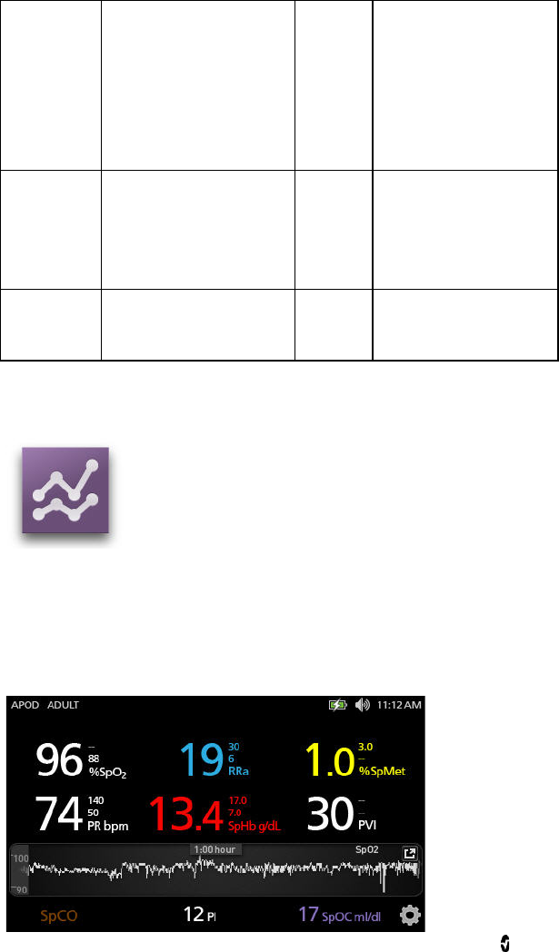
Radical-7 Chapter 4: Operation
www.masimo.com 81 Masimo
Analog 2
Depending on the
configuration, the following
parameters are output
continuously on the Analog 1
and Analog 2.
N/A Pleth, SIQ, 0V Output, 1V
Output, SpO2 0% to 100%,
SpO2 50% to 100%, or Pulse
rate
Nurse Call
Trigger The nurse call output will be
activated based on the alarm
events. The nurse call with be
activated based on Low Signal
or Alarm and Low Signal IQ
events.
N/A Alarms + SIQ, SIQ, Alarms
Nurse Call
Polarity Can be inverted to
accommodate various nurse
call station requirements.
N/A Normal or Inverted
Trends
The following sections describe Trend Views and how to adjust trend settings.
About Trend Views
There are different ways to view trend information. The following is an example of trend
information for SpO2 as it appears within the Display View screen.
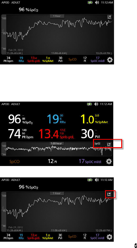
Radical-7 Chapter 4: Operation
www.masimo.com 82 Masimo
The following is an example of trend information for SpO2 as it appears in the Full Trend
screen.
Changing Between Trend Views
To toggle between Display View and Full Trend
From the Display View, in the Trend Field, touch the icon as shown below.
From the Full Trend screen, touch the icon as shown below.

Radical-7 Chapter 4: Operation
www.masimo.com 83 Masimo
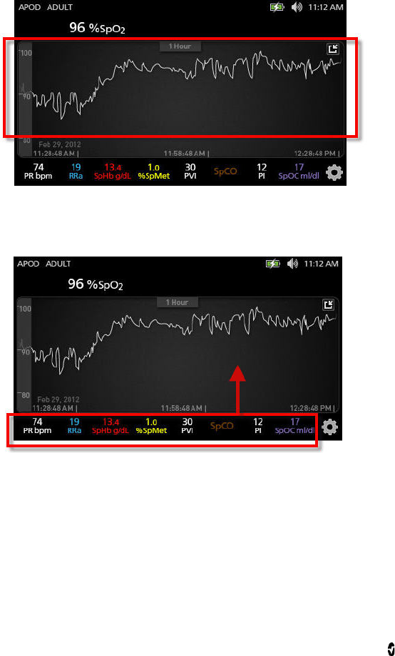
Radical-7 Chapter 4: Operation
www.masimo.com 84 Masimo
Manipulating Trend Data
To manipulate the view of trend data
On the Full Trend screen, with a pinch gesture, using two fingers, the user can zoom in and out
of the trend time scale.
The user can add parameters to the Trend view by dragging and dropping parameters from
the Small Parameter view. To add a parameter to the Trend view, press and hold any of the
parameters inside the Small Parameter view, as shown below. When the parameter dims,
shakes, and grows in size, drag and drop the parameter into the Trend view.
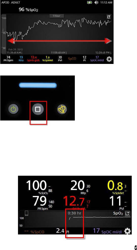
Radical-7 Chapter 4: Operation
www.masimo.com 85 Masimo
To view past patient trend data, swipe the trend display to the left or to the right.
To exit a Trend view, press the Home button.
Changing the Time Interval of Trend Data
Users can change the time interval of trend data. The time options that can be selected are
10 minutes, 30 minutes, 1 hour, 2 hours, 4 hours, 8 hours, 12 hours, or 24 hours.
To change the time interval of trend data
1. From the Display View, in the Trend Field, or from the the Full Trend screen, touch
the Time Interval icon.
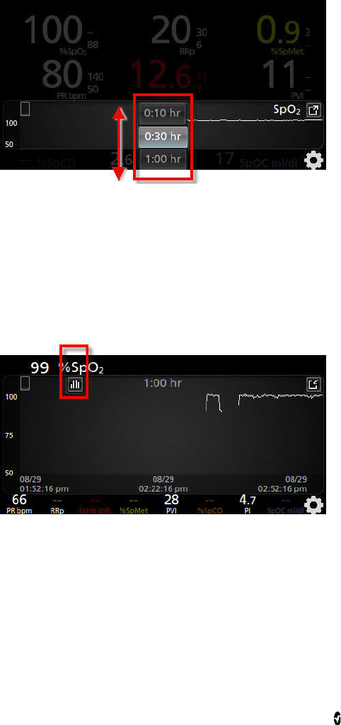
Radical-7 Chapter 4: Operation
www.masimo.com 86 Masimo
2. Scroll up or down to select a time interval.
Using the Histogram Feature
Users can view trend data using the Histogram feature. When turned on, the Histogram
feature displays trend data as a histogram.
To turn on the Histogram feature
1. Navigate to a Full Trend screen. See Changing Between Trend Views on page 82.
2. The Histogram icon appears along the top of the Trend Field, as shown in the
following example for SpO2.
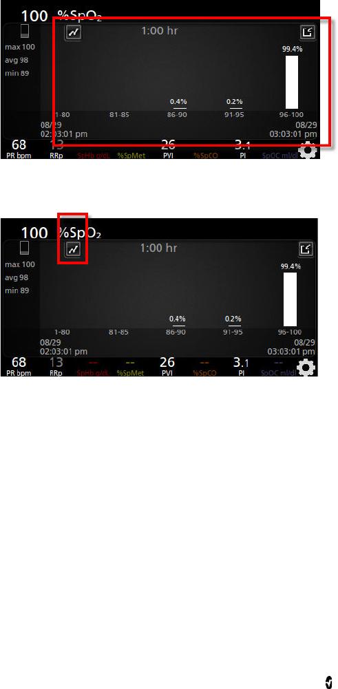
Radical-7 Chapter 4: Operation
www.masimo.com 87 Masimo
3. Touch the Histogram icon.
4. Trend data displays as a histogram.
To turn off the Histogram feature
• Touch the Trends icon, as shown.
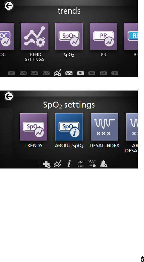
Radical-7 Chapter 4: Operation
www.masimo.com 88 Masimo
Changing Trend Settings
There are several ways to access and then change the maximum value and the minimum
value of the Y axis for any of the available parameters.
To access the trend settings for any of the available parameters
1. From the Main Menu screen, touch the Trends icon.
2. From the Trends screen, touch any of the available parameters.
Alternatively, from any Parameter Settings screen, touch the Trends icon.
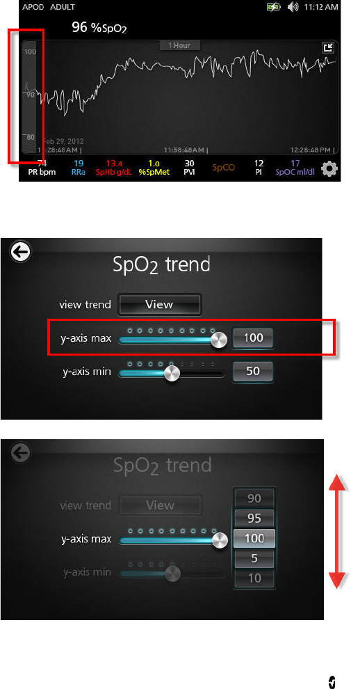
Radical-7 Chapter 4: Operation
www.masimo.com 89 Masimo
Alternatively, from the Display View or from the Full Trend view, touch the Y axis
range on the left side of the screen as shown. When viewing trends for an
additional parameter, the Y axis range appears on the right side of the screen.
To change the trend settings for any of the available parameters
1. Touch the slider for the Y-axis maximum or the Y-axis minimum.The following is
an example of the SpO2 Trend screen.
2. Select the desired setting by scrolling up or down.
3. When finished, select OK.
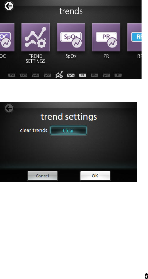
Radical-7 Chapter 4: Operation
www.masimo.com 90 Masimo
Deleting Trend Data
The user can delete patient trend data that has been stored on the Radical-7.
To delete patient trend data
1. From the Trends screen, touch the Trend Settings icon.
2. From the Trend Settings screen, touch Clear, and then touch OK. This deletes all
stored trend data.

Radical-7 Chapter 4: Operation
www.masimo.com 91 Masimo
About
For information about parameters, see About Parameter Information on page 60.
From the About screen, view any of the following options:
Options Description
Serial Number Displays the serial number of the Handheld.
MCU Displays the version number of the instrument board software.
MX Board Displays the version number of the technology level software.
Processor Displays the version number of the system level software.
Docking
Station If docked, displays the current software version of the Docking Station.
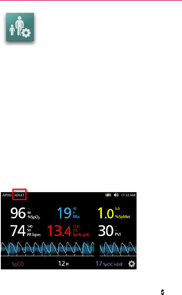
www.masimo.com 93 Masimo
Chapter 5: Profiles
The Radical-7 can be configured for various patient types.
Profiles Overview
The Radical-7 contains a Profiles screen, which lets the user customize different settings for
different patient populations:
• Adult
Adult profile is the factory default profile. Displays in the Status bar as ADULT and
the color of the Profile button turns blue.
• Neonatal
Displays in the Status bar as NEO and the color of the Profile button turns pink.
• Custom
Displays in the Status bar as CUSTOM and the Profile button is not illuminated
and appears gray.
If no changes are made to settings, then after a power cycle, the Radical-7 automatically
resets to the Adult profile because Adult is the factory default profile.
If the Profile setting is changed to NEO or CUSTOM, then after a power cycle, the Radical-7
remembers the previously selected Profile setting.
The active profile displays in the Status Bar. In the following example, the Adult profile is
active.
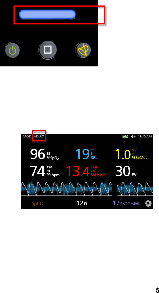
Radical-7 Chapter 5: Profiles
www.masimo.com 94 Masimo
The Radical-7 conveys the active profile by changing the color of the Profiles button.
To restore all Radical-7 settings to factory default settings, see Access Control on page 76.
Changing Profiles
Changing Profiles is done in the Profiles Settings screen. There are different ways to access
the Profiles Settings screen.
• The first way is by the touching the Profiles shortcut in the Status Bar, as show
below.
• Another way to access the Profiles Settings screen is by pressing the Profile button,
as shown below.
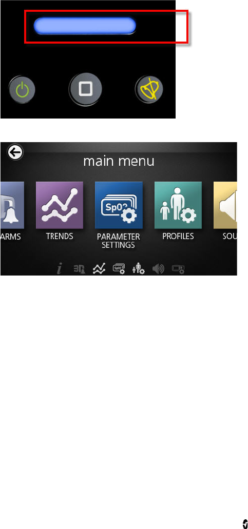
Radical-7 Chapter 5: Profiles
www.masimo.com 95 Masimo
• Alternatively, from the Main Menu screen, touch the Profiles icon.
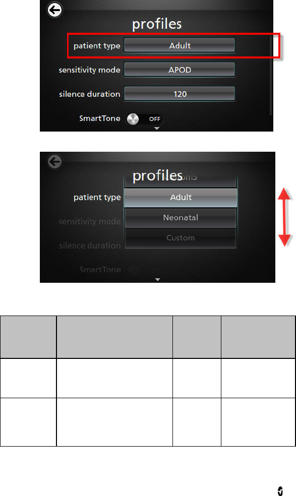
Radical-7 Chapter 5: Profiles
www.masimo.com 96 Masimo
To change Patient Type
1. From the Profile screen, touch the Patient Type field.
2. Select the desired Patient Type by scrolling up or down.
3. When finished, touch OK. To confirm selection, check the Status Bar.
From the Profiles screen, change any of the following options:
Options Description Factory
Default
Settings
User Configurable
Settings
Patient Type Defines the patient population
for which the device will operate. Adult Neonatal, Adult,
Custom, or Custom 1
to 5
Sensitivity
Modes Defines the sensitivity level for
which the device will operate.
See Sensitivity Modes Overview
on page 55.
APOD MAX, APOD, or
NORM
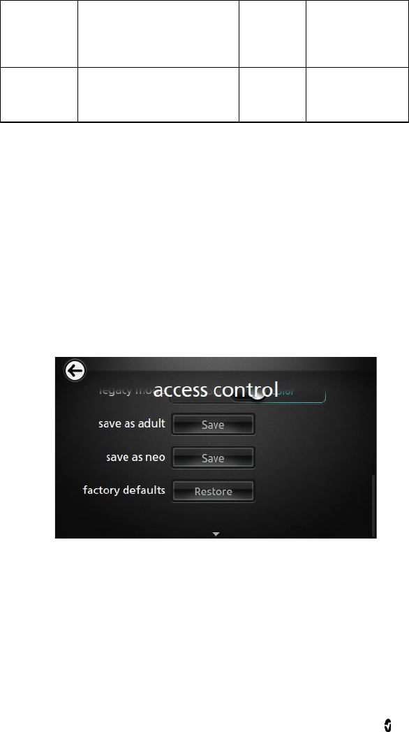
Radical-7 Chapter 5: Profiles
www.masimo.com 97 Masimo
Silence
Duration The amount of time for which the
audible part of an alarm will be
silenced. See Silencing the
Alarms on page 99.
120 30, 60, 90, 120
seconds
Smart Tone Allows the audible pulse to
continue to beep when the pleth
graph shows signs of motion.
Off On or Off
Replacing Factory Default Settings for Adult and Neo Profiles
The Adult profile and the Neonatal profile can be modified to meet specific requirements and
then they can replace the factory default settings for Adult and Neonatal profiles. As such,
after a power cycle, the Radical-7 remembers the preferred settings for Adult and Neonatal
instead of the factory default settings. When preferred settings for Adult and Neonatal are
saved instead of the factory default settings, the Profile button changes to same blue or pink
color. See Profiles Overview on page 93.
A user can also load preferred profile configurations into the Radical-7 using a separate tool.
To change the factory default settings for Adult or Neonatal profile settings
1. Make the preferred changes to any of the Radical-7 settings.
2. Navigate to the Access Control screen. See Access Control on page 76.
3. For either Adult or Neonatal, touch Save.
4. Touch Ok.
5. Alternatively, the user can restore all Profile settings to their factory default values
by touching Restore, and then touching Ok.
6. Confirm the changes by powering off and powering on the Radical-7 and then
verifying settings.
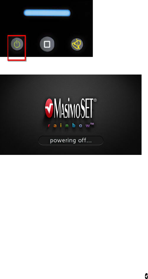
Radical-7 Chapter 5: Profiles
www.masimo.com 98 Masimo
Powering Off the Radical-7
When turning off the Radical-7, the device remembers the preferred settings.
To turn off the Radical-7
1. Press and hold the button for more than 2 seconds.
2. To confirm the shutdown process, the following screen appears.
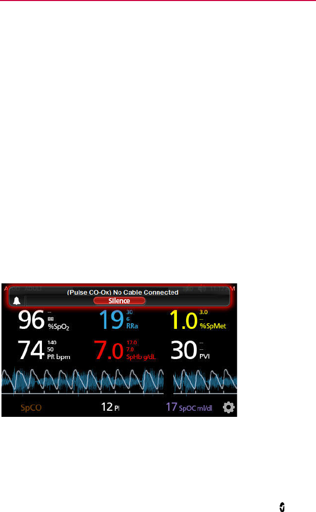
www.masimo.com 99 Masimo
Chapter 6: Alarms and Messages
The following chapter contains information about alarms and messages.
For more information, see Chapter 7: Troubleshooting on page 111.
About Alarms
The Radical-7 visually and audibly indicates alarm conditions that the system detects.
Audible alarms may be silenced, without affecting the operation of visual alarms. See Safety
Information, Warnings, and Cautions on page 11 and Alarm Related Safety Information,
Warnings, and Cautions on page 20.
There are three priorities for alarms:
• High
• Medium
• Low
Alarm Delay
When an alarm condition is met, this feature delays the audible part of an alarm.
Silencing the Alarms
Alarms are conveyed in ways: audible, visual, or both.
The following is an example of a visual alarm for an exception message:
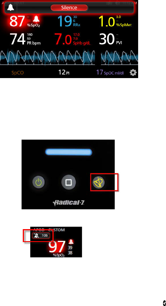
Radical-7 Chapter 6: Alarms and Messages
www.masimo.com 100 Masimo
The following is an example of a typical alarm due to parameter limit violation.
To silence or dismiss alarms:
• Touch Silence (the highlighted area of the Status Bar).
Audible alarms can be temporarily suspended by pressing the Alarm Silence button. When
alarms are in the suspend state, pressing the Alarm Silence button cancels the alarm
suspend.
To silence audible alarms
1. When an audible is active, push Alarm Silence one time.
2. The audible alarm is silenced for up to 120 seconds and a countdown timer
displays.
3. The length of time for which an audible alarm remains silenced (suspended) can
be changed using the Silence Duration feature located on the Sounds screen. See
Sounds on page 74.

Radical-7 Chapter 6: Alarms and Messages
www.masimo.com 101 Masimo
Adaptive Threshold Alarm (ATA) Feature
The Adaptive Threshold Alarm (ATA) feature is an optional feature that provides continuous
SpO2 surveillance while allowing the clinician a useful tool to help reduce the frequency of
audible alarms.
ATA establishes the alarm limit threshold based upon the patient-specific baseline value of
the SpO2 parameter which is determined from the recent history of SpO2 values. An Adaptive
Threshold Limit is continuously determined for the patient and SpO2 values outside the
Adaptive Threshold Limit trigger an audible alarm. The Adaptive Threshold Limit is bound by
the standard SpO2 low alarm limit and the Rapid Desat low alarm limit. SpO2 values that
exceed the Rapid Desat limit, whether it occurs rapidly or not, will activate an audible alarm.
Prior to activating ATA, please review and select the appropriate standard low alarm limit and
other alarm settings. Once ATA is selected, the Rapid Desat Alarm protection is always active.
If the ATA low alarm limit is violated, ATA generates an audible alarm.
It is important to note that once activated, ATA has the following automatic safety features:
Reminder Tones
If an SpO2 value from a patient drops below the standard low alarm limit set by the user, a
visual alert will display and a reminder tone will repeat every 15 minutes as long as the
condition persists. If the SpO2 value drops below the ATA low alarm limit, an audible alarm
will be activated.
Rapid Desat Alarm Protection
The Rapid Desat feature is always active when ATA is turned on. This means that deep
desaturations (5% or 10%) from the standard SpO2 low alarm limit immediately generate an
audible alarm. When used with ATA, it also serves as absolute low alarm limit protection.
SpO2 values exceeding the Rapid Desat low alarm limit, whether rapid or not, will activate an
audible alarm. The user can change the Rapid Desat default setting from 5% to 10%. ATA does
not allow a Rapid Desat default setting of 0%.
When ATA is turned Off, the instrument uses the standard alarm limits and standard alarm
delays.
About Alarms on page 99.
Alarms for SpO2 on page 62.

Radical-7 Chapter 6: Alarms and Messages
www.masimo.com 102 Masimo
3D Alarms
3D Alarms include the Desat Index Alarm and the PI Delta Alarm.
Desat Index Alarm Overview on page 102.
Perfusion Index (PI) Delta Alarm Overview on page 103.
Desat Index Alarm Overview
The Desat Index Alarm is a user-selectable feature which allows a clinician to request an
audible and visual alarm if a patient experiences a specified number of desaturations over a
specific period of time.
Traditional high and low SpO2 alarm limits alert clinicians to saturation levels that exceed
user selected thresholds, and these thresholds are typically established at a considerable
change from the patients’ baseline saturation level. However, in select patient populations,
substantial desaturation events that exceed a typical low alarm limit threshold may be
preceded by a cycle of transient desaturations over a limited timeframe, and the ability to
alert clinicians to a cycle of these smaller desaturations may provide an earlier indication of a
potential significant decline in the patient’s status and the need for more focused monitoring
and/or a change in treatment.
To address patient populations at risk for cyclic, moderate desaturations, the option
includes a user-selectable Desat Index Alarm which allows the clinician to request an audible
and visual alarm in the event the patient experiences a specified number of desaturations
beyond a defined level from the patient’s baseline saturation over a specific window of time,
with each of these variables selectable by the user within established ranges as noted in
Desat Index Settings on page 102.
Desat Index Settings
From the Desat Index Settings screen, access the following screens:
Desat Index Alarms on page 103.
About Parameter Information on page 60.

Radical-7 Chapter 6: Alarms and Messages
www.masimo.com 103 Masimo
Desat Index Alarms
From the Alarms screen, change any of the following options:
Options Description Factory Default
Settings User Configurable
Settings
Delta See Desat Index Alarm
Overview on page 102. 4% 2% to 10% in steps of
1%.
Time See Desat Index Alarm
Overview on page 102. 1 hour 1 to 4 hours, in steps
of 1.
# of Events See Desat Index Alarm
Overview on page 102. Off Off, 1 to 24
desaturations in
steps of 1.
Perfusion Index (PI) Delta Alarm Overview
The PI Delta Alarm is a user-selectable feature which allows a clinician to request an audible
and visual alarm if perfusion at the monitored site decreases by a specified level (delta) over
a specific period of time.
Perfusion Index gives an indication of the level of perfusion at the monitored site. The
Radical-7 measures perfusion at the SpO2 site by comparing the pulsatile signal to the
non-pulsatile signal, and expressing that ratio as a percentage. PI has been clinically proven
to be useful as a predictor of the level of illness in neonates and adults and that PI may
change dramatically in response to sympathetic changes caused by inhalational agents and
pain stimulation*. If PI decreases over time, there may be underlying physiological reasons
that may need to be addressed.
The PI Delta provides an audible and visual alert to important changes in perfusion compared
to the patient’s baseline PI rate. The baseline is set by the Radical-7 once the user has
enabled the alarm. The baseline is 30 seconds of currently averaged PI. The feature includes
a user-selectable PI Delta Alarm. This allows the clinician to request an audible and visual
alarm if perfusion at the monitored site decreases by a specified level (delta) over a specified
window of time. Three of the variables are selectable by the user within established ranges as
noted in PI Delta Settings on page 103.
*De Felice C, Latini G, Vacca P, Kopotic RJ. The pulse oximeter perfusion index as a predictor for
high illness severity in neonates. Eur J Pediatr. 2002;161:561-562.
PI Delta Settings
From the PI Delta Settings screen, access the following screens:
Perfusion Index (PI) Delta Alarm Overview on page 103.
About Parameter Information on page 60.

Radical-7 Chapter 6: Alarms and Messages
www.masimo.com 104 Masimo
PI Delta Alarms
From the Alarms screen, change any of the following options:
Options Description Factory
Default
Settings
User Configurable Settings
Set Baseline See Perfusion Index (PI)
Delta Alarm Overview on
page 103.
Off On or Off
Baseline See Perfusion Index (PI)
Delta Alarm Overview on
page 103.
Off, or PI
baseline N/A
Percent
Change See Perfusion Index (PI)
Delta Alarm Overview on
page 103.
50% 10% to 99% in steps of 1%
Timeout See Perfusion Index (PI)
Delta Alarm Overview on
page 103.
None 1 min, 5 min, 30 min, 1 hr, 4
hr, 8 hr, 12 hr, 24 hr, 36 hr,
48 hr, or None.
Messages
The following section lists common messages, their potential causes, and next steps.
Replace Sensor Message
Message:
• (Pulse CO-Ox) Replace Sensor, or
• (RAM) Replace Sensor
SpHb reusable sensor has used all its available monitoring time. Sensor is non-functional.
Defective sensor.
Next steps: Replace sensor.

Radical-7 Chapter 6: Alarms and Messages
www.masimo.com 105 Masimo
Replace Cable Message
Message:
• (Pulse CO-Ox) Replace Cable, or
• (RAM) Replace Cable
The patient cable is non-functional or the life of the cable has expired.
Next steps: Replace the patient cable.
Replace Adhesive Sensor Message
Message:
• (Pulse CO-Ox) Replace Adhesive Sensor, or
• (RAM) Replace Adhesive Sensor
When a single-patient-use sensor is used, the adhesive portion of the sensor is
non-functional, or the life of the adhesive portion of the sensor has expired. (Applies to
Rainbow ReSposable CO-Oximeter Sensor Systems or ReSposable Pulse Oximeter Sensor
Systems only.)
Next steps: Replace the adhesive portion of the sensor.
Incompatible Sensor Message
Message:
• (Pulse CO-Ox) Incompatible Sensor, or
• (RAM) Incompatible Sensor
Not a proper Masimo sensor.
Next steps: Replace with a proper Masimo sensor.
SpHb sensor is attached to a instrument without SpHb installed.
Next steps: Use a non-SpHb sensor. Contact your local Masimo Representative to learn more
about the optional SpHb upgrade.
Incompatible Adhesive Sensor Message
Message:
• (Pulse CO-Ox) Incompatible Adhesive Sensor, or
• (RAM) Incompatible Adhesive Sensor
Not a proper Masimo sensor.
Next steps: Replace with a proper Masimo sensor.
SpHb sensor is attached to a instrument without SpHb installed.
Next steps: Use a non-SpHb sensor. Contact your local Masimo Representative to learn more
about the optional SpHb upgrade.

Radical-7 Chapter 6: Alarms and Messages
www.masimo.com 106 Masimo
No Adhesive Sensor Connected Message
Message:
• (Pulse CO-Ox) No Adhesive Sensor Connected, or
• (RAM) No Adhesive Sensor Connected
When a single-patient-use sensor is used, the adhesive portion of the sensor is not
connected. (Applies to Rainbow ReSposable CO-Oximeter Sensor Systems or ReSposable
Pulse CO-Oximeter Sensor Systems only.)
Next steps: Ensure the adhesive portion is firmly connected to the sensor.
Interference Detected Message
Message:
• (Pulse CO-Ox) Interference Detected, or
• (RAM) Interference Detected
High intensity light such as pulsating strobe lights, excessive ambient light sources such as
surgical lights or direct sunlight, or other monitor displays.
Next steps: Place a Masimo Optical Light Shield over the sensor.
Incorrect monitor line frequency setting (Hz).
Next steps: . Adjust the Line Frequency to the correct Hz setting. See Device Settings on
page 75.
SpO2 Only Mode Message
Message: (Pulse CO-Ox) SpO2 Only Mode
Occurs during an unsuccessful sensor initialization/pulse search routine or during
monitoring.
Next steps: See the directions for use provided with your sensor. Use a Masimo light shield to
cover the sensor and adjust the sensor.
Low Battery Message
Battery charge is low.
Next steps: Charge battery by placing the Handheld into the Docking Station and powering
the instrument with AC line power. Replace battery if necessary.
Low Perfusion Index Message
Message: (Pulse CO-Ox) Low Perfusion Index
Signal too small.
Next steps: Move sensor to better perfused site. See Low Perfusion on page 112.

Radical-7 Chapter 6: Alarms and Messages
www.masimo.com 107 Masimo
Low Signal IQ Message
Message: (Pulse CO-Ox) Low Signal IQ
Low signal quality.
Next steps: Ensure proper sensor application. Move sensor to a better perfused site. See
Signal IQ (SIQ) on page 111.
Low SpCO SIQ Message
SpCO measurement reading is obscured.
Next steps: Ensure proper sensor application. Check sensor to see if it is working properly. If
not, replace the sensor. See Successful Monitoring for SpCO on page 28.
Low SpMet SIQ Message
SpMet measurement reading is obscured.
Next steps: Ensure proper sensor application. Check sensor to see if it is working properly. If
not, replace the sensor. See Successful Monitoring for SpCO on page 28.
Low SpHb SIQ Message
SpHb measurement reading is obscured.
Next steps: Ensure proper sensor application. Check sensor to see if it is working properly. If
not, replace the sensor. See Successful Monitoring for SpHb on page 27.
Speaker Failure Message
Instrument requires service. Next steps: Contact Masimo Tech Support. Chapter 9: Service
and Maintenance on page 131.
No Cable Connected Message
Message:
• (Pulse CO-Ox) No Cable Connected, or
• (RAM) No Cable Connected
Cable not attached or not fully inserted into the connector.
Next steps: Disconnect and reconnect cable into connector.

Radical-7 Chapter 6: Alarms and Messages
www.masimo.com 108 Masimo
No Sensor Connected Message
Message:
• (Pulse CO-Ox) No Sensor Connected, or
• (RAM) No Sensor Connected
Sensor not fully inserted into the connector. May be an incorrect sensor or a defective sensor
or cable.
Next steps: Disconnect and reconnect sensor. See the instructions for use provided with your
sensor.
Instrument is searching for patient’s pulse.
Next steps: Disconnect and reconnect the sensor into the Patient Cable connector.
Sensor is disconnected from patient cable. Sensor connected upside down into patient cable.
Next steps: Check to see if the sensor LED is flashing. Disconnect and reconnect the sensor. If
the LED fails to operate, replace the sensor.
Pulse Search Message
Message: (Pulse CO-Ox) Pulse Search
Instrument is searching for pulse.
Next steps: If instrument fails to display within 30 seconds, disconnect and reconnect. If
pulse search continues, move sensor to better perfused site.
Sensor Initializing Message
Message: (Pulse CO-Ox) Sensor Initializing
Instrument is checking the sensor for proper functioning and performance.
Next steps: If values are not displayed within 30 seconds, disconnect and reconnect sensor.
If values are still not displayed, replace with a new sensor.
Sensor Off Patient Message
Message:
• (Pulse CO-Ox) Sensor Off Patient, or
• (RAM) Sensor Off Patient
Sensor off patient.
Next steps: Disconnect and reconnect sensor. Reattach sensor.
Sensor not connected to patient properly. Sensor is damaged.
Next steps: Properly reapply the sensor on the patient and reconnect the sensor to the
instrument or patient cable. If the sensor is damaged, replace the sensor.

Radical-7 Chapter 6: Alarms and Messages
www.masimo.com 109 Masimo
Incompatible Cable Message
Message: (Pulse CO-Ox) Incompatible Cable
Not a proper cable.
Next steps: Replace with a proper cable.

www.masimo.com 111 Masimo
Chapter 7: Troubleshooting
The following chapter contains information about troubleshooting the Radical-7 system.
Troubleshooting Measurements
See Parameter Related Safety Information, Warnings, and Cautions on page 11.
Signal IQ (SIQ)
The Signal IQ provides an indicator of the assessment of the confidence in the displayed
SpO2 value. The SpO2 SIQ can be also used to identify the occurrence of a patient’s pulse.
With motion, the plethysmographic waveform is often distorted and may be obscured by
artifact. Shown as a vertical line, the SpO2 SIQ coincides with the peak of an arterial
pulsation. Even with a plethysmographic waveform obscured by artifact, the Signal IQ
identifies the timing that the algorithms have determined for the arterial pulsation. The
pulse tone (when enabled) coincides with the vertical line of the SpO2 SIQ.
The height of the vertical line of the SpO2 SIQ provides an assessment of the confidence in
the measurement displayed. A high vertical bar indicates higher confidence in the
measurement. A small vertical bar indicates lower confidence in the displayed
measurement. When the Signal IQ is very low, this suggests that the accuracy of the
displayed measurement may be compromised. See About the Status Bar on page 49.
When parameters are dimly lit, proceed with caution and do the following:
• Assess the patient.
• Check the sensor and ensure proper sensor application. The sensor must be well
secured to the site for the Radical-7 Pulse CO-Oximeter to maintain accurate
readings. Misalignment of the sensor’s emitter and detector can result in smaller
signals and cause erroneous readings.
• Determine if an extreme change in the patient’s physiology and blood flow at the
monitoring site occurred, (e.g. an inflated blood pressure cuff, a squeezing motion,
sampling of an arterial blood specimen from the hand containing the pulse
oximetry sensor, severe hypotension, peripheral vasoconstriction in response to
hypothermia, medications, or an episode of Raynaud’s syndrome.)
• With neonates or infants, check that the peripheral blood flow to the sensor site is
not interrupted. Interruption, for example, may occur while lifting or crossing their
legs during a diaper change.
• After performing the above, if the parameter remains dimly lit frequently or
continuously, obtaining an arterial blood specimen for CO-Oximetry analysis may
be considered to verify the oxygen saturation value.
See Parameter Related Safety Information, Warnings, and Cautions on page 11.

Radical-7 Chapter 7: Troubleshooting
www.masimo.com 112 Masimo
Dimly Lit Parameters
When the signal quality is very low, the accuracy of measurements may be compromised, the
parameter may be dimly lit, and the parameter may display dashes instead of a numeric
value.
Low Perfusion
It has been suggested that at extremely low perfusion levels, pulse oximeters can measure
peripheral saturation, which may differ from central arterial saturation This "localized
hypoxemia" may result from the metabolic demands of other tissues extracting oxygen
proximal to the monitoring site under conditions of sustained peripheral hypoperfusion. This
may occur even with a pulse rate that correlates with the ECG heart rate.
Low Signal Quality
Improper sensor type or application.
Next steps: Excessive motion relative to perfusion. Sensor is damaged or not functioning.
Check and see if blood flow to the site is restricted. Check the placement of the sensor.
Reapply sensor or move to a different site. See Appendix: Best Practices for Comparisons to
Reference Measurements on page 139.
SpO2 Values Do Not Correlate With Clinical Assessment or Arterial
Blood Gas Measurements
Low perfusion or sensor displacement.
Next steps: Check for error messages. See Chapter 6: Alarms and Messages on page 99.
Check placement of sensor or if it is too tight. Reapply sensor or select a new site. Set to MAX
sensitivity and confirm that the sensor is securely on the patient. See the directions for use
provided with your sensor.
Unexpected SpO2, SpCO, SpMet, or SpHb Reading
• Low SIQ or PI values.
Next steps: Reposition sensor to site with strong SIQ and PI. Average readings
taken from three different sites to improve accuracy. Submit blood sample for
laboratory CO-Oximetry test for comparison.
• Inappropriate sensor size or sensor measurement location.
Next steps:Verify proper sensor for patient size. Verify proper sensor site. See
Appendix: Best Practices for Comparisons to Reference Measurements on page
139.

Radical-7 Chapter 7: Troubleshooting
www.masimo.com 113 Masimo
Unexpectedly High SpCO Reading
Possible elevated methemoglobin level.
Next steps: Submit blood sample for laboratory CO-Oximetry test. See Appendix: Best
Practices for Comparisons to Reference Measurements on page 139.
Difficulty Obtaining a Reading
• Low battery/ not plugged into AC power supply.
Next steps: Insert Handheld into Docking Station, verify Docking Station power
cord plugged in and Docking Station power indicator light is illuminated.
• Interference from line frequency induced noise.
Next steps: Verify/set 50/60hz menu setting. See Localization on page 78.
• Inappropriate sensor or sensor size.
Next steps: Verify proper sensor and sensor size for the patient.
• Excessive ambient or strobing light.
Next steps: Shield the sensor from excessive or strobing light. Minimize or
eliminate motion at the monitoring site. See Appendix: Best Practices for
Comparisons to Reference Measurements on page 139.
SpCO Reading Displays as Dashes
• SpO2 value below 90% Next steps: Assess/address patient condition.
• SpMet value greater than 2% Next steps: Laboratory analysis of a blood sample
should be performed.
• SpCO parameter has not yet stabilized during initial startup
Next steps: Verify proper sensor and sensor size for the patient. Allow time for
parameter reading to stabilize. See Appendix: Best Practices for Comparisons to
Reference Measurements on page 139.
Troubleshooting the Radical-7
For more information, see Chapter 6: Alarms and Messages on page 99.
Instrument Does Not Turn On
One or both of the fuses are not operating properly.
Next steps: Replace the fuses. For details, see Replacing the Fuses on page 133.
Instrument Turns On But Screen is Blank
The viewing contrast is not correct.
Next steps: Adjust the brightness setting. See Brightness on page 80. If the condition
persists, requires service. See. Contacting Masimo on page 136.

Radical-7 Chapter 7: Troubleshooting
www.masimo.com 114 Masimo
Continuous Speaker Tone
Internal failure.
Next steps: To silence an alarm, press the Alarm Silence button. If alarm continues to sound,
turn off the Radical-7. If necessary, remove Handheld battery. Requires service. See
Contacting Masimo on page 136.
Buttons Do Not Work When Pressed
Internal failure.
Next steps: Requires service. See Contacting Masimo on page 136.
Handheld Battery Does Not Charge
AC power cable may be disconnected.
Next steps: Restore power to the instrument.
Battery Run Time Significantly Reduced
Battery memory effects. Next steps: See Battery Operation and Maintenance on page 131.
Indicators on Docking Station Continuously Flash
Incompatible version of software on Handheld and Docking Station.
Next steps: Upgrade to current software versions. Match Handheld to Docking Station with
compatible software versions.

www.masimo.com 115 Masimo
Chapter 8: Specifications
The following chapter contains specifications for the Radical-7 Handheld, compatible Docking
Stations, and the Standalone system.
Measurement Range
Measurement Display Range
SpO2 (Oxygen Saturation) 0% to 100%
SpMet (Methemoglobin) 0% to 99.9%
SpCO (Carboxyhemoglobin) 0% to 99%
SpHb (Hemoglobin) 0 g/dL to 25.0 g/dL
SpOC (Oxygen Content) 0 ml of O2/dL to 35 ml of O2/dL of blood
PR (Pulse Rate) 25 bpm to 240 bpm
PI (Perfusion Index) 0.02% to 20%
PVI (Pleth Variability Index) 0% to 100%
RRa (Respiration Rate) 0 breaths per minute to 70 breaths per
minute
RRp (Respiration Rate) 0 breaths per minute to 70 breaths per
minute
Accuracy
Oxygen Saturation Accuracy [1]
No Motion 60% to 80%
Adults, Infants, Pediatrics ±3%

Radical-7 Chapter 8: Specifications
www.masimo.com 116 Masimo
No Motion [2] 70% to 100%
Adults, Infants, Pediatrics ± 2%
Neonates ± 3%
Motion [3] 70% to 100%
Adults, Infants, Pediatrics, Neonates ± 3%
Low Perfusion [4]
Adults, Infants, Pediatrics, Neonates ± 2%
Pulse Rate Accuracy
Pulse rate range 25 bpm to 240 bpm
No Motion
Adults, infants, pediatrics, neonates ± 3 bpm
Motion [4]
Adults, infants, pediatrics, neonates ± 5 bpm
Low Perfusion
Adults, infants, pediatrics, neonates ± 3 bpm
Carboxyhemoglobin Accuracy [1]
Adults, infants, pediatrics 1% to 40% ± 3%
Methemoglobin Saturation Accuracy [1]
Adults, infants, pediatrics, neonates 1% to 15% ± 1%
Total Hemoglobin Accuracy [6]
Adults, pediatrics 8 g/dL to 17 g/dL ±1 g/dL

Radical-7 Chapter 8: Specifications
www.masimo.com 117 Masimo
Respiratory Rate Accuracy (RRa) [11]
Adults, pediatrics 0 breaths per minute to 70 breaths per
minute, ±1 breath per minute
Respiratory Rate Accuracy (RRp) [11]
Adults, pediatrics 0 breaths per minute to 70 breaths per
minute, ±1 breath per minute
Resolution
Parameter Step Size
%SpO2 1%
%SpCO 1%
%SpMet 0.1%
SpHb g/dL 0.1 g/dL
Pulse Rate 1 beats per minute
Respiration Rate 1 breath per minute
Electrical
Standalone
AC Power requirements 100 to 240 VAC, 47 to 63 Hz
Power consumption 55 VA
Fuses 1 Amp, Fast Acting, Metric, (5x20mm),
250V
Handheld Battery
Type Lithium ion

Radical-7 Chapter 8: Specifications
www.masimo.com 118 Masimo
Capacity 4 hours [7]
Time 3 hours
Environmental
Operating Temperature 32°F to 122°F
(0°C to 50°C)
Transport/Storage Temperature -40°F to 158°F
(-40°C to 70°C) [8]
Operating Humidity 10% to 95%, non-condensing
Operating Altitude 500 mbar to 1060 mbar
-1000 ft to 18,000 ft
(-304 m to 5,486 m)
Physical Characteristics
Dimensions
Handheld 8.9” x 3.5” x 2.1”
(22.6 cm x 8.9cm x 5.3 cm)
Standalone 3.5” x 10.5” x 7.7”
(8.9 cm x 26.7 cm x 19.6 cm)
Weight
Handheld 1.2 lbs. (0.54 kg)
Docking Station (RDS-1, RDS-2, RDS-3) 2.5 lbs. (1.14 kg)
Standalone (RDS-1, RDS-2, RDS-3) 3.8 lbs. (1.73 kg)
Trending
• Max of 96 hours of trending at 2-second resolution
Sensitivity NORM, MAX, and APOD [10]

Radical-7 Chapter 8: Specifications
www.masimo.com 119 Masimo
Alarms
Parameter Alarm Range
SpO2 1% to 99%
SpCO 1% to 98%
SpMet 0.1% to 99.5%
SpHb 1.0 g/dL to 24.5 g/dL
RR 5 breaths per minute to 69 breaths per
minute
PI 0.03% to 19%
PVI 1% to 99%
Pulse Rate 30 bpm to 235 bpm
SpOC 1 g/dL to 34 g/dL
Sensor condition, system failure, and low battery alarms
High Priority 571 Hz tone, 5-pulse burst, pulse spacing:
0.250s, 0.250s, 0.500s, 0.250s, repeat
time:10s
Medium Priority 550 Hz tone, 3-pulse burst, pulse spacing:
0.375s, 0.375s, repeat time: 7s
Low Priority 500 Hz tone, 1-pulse burst, repeat time: 5s
Alarm Muted Reminder 500Hz tone, 2-pulse burst, pulse spacing
0.375s, repeat time: 3 min
Alarm Volume High Priority: 70 dB (min)
Medium Priority: 70 dB (min)
Low Priority: 45 dB (min)

Radical-7 Chapter 8: Specifications
www.masimo.com 120 Masimo
Display Indicators
Display Update Rate 1 second
Response Time < 20 second delay
Type Backlit Active Matrix TFT LCD
Pixels 480 dots x 272 dots
Dot Pitch 0.25 mm

Radical-7 Chapter 8: Specifications
www.masimo.com 121 Masimo
Compliance
EMC Compliance
• EN55011: Radiated Emissions (CISPRR 11, 2009 Amendment A1:2010, Class B)
• EN55011: Conducted Emissions (CISPRR 11, 2009 Amendment A1:2010, Class B)
• EN301 489-17: Radiated Emissions (EN 301 489-01 V1.8.1:2008, Class B)
• EN301 489-17: Conducted Emissions (EN 301 489-01 V1.8.1:2008, Class B)
• EN61000-3-2: Limitations of quasi-stationary current Harmonic Emissions
(Requirements from EN 60601-1-2:2007)
• EN301 489-17: Harmonic Emissions (EN 301 489-01 V1.8.1:2008)
• EN61000-3-3: Limitations of voltage fluctuations and Flicker
• EN301 489-17: Flicker (EN 301 489-01 V1.8.1:2008)
• EN61000-4-2: ESD: Direct, Indirect, Vertical and Horizontal coupling plane
• EN301 489-17: ESD: Direct, Indirect, Vertical and Horizontal coupling plane (EN
301 489-01 V1.8.1:2008)
• EN61000-4-3: Radio Frequency Electromagnetic Field (80MHz to 2500MHz) at
3V/m, 2 Hz sine wave, 3 sec dwell
• EN301 489-17: Radio Frequency Electromagnetic Field (80MHz to 2500MHz) at
3V/m (EN 301 489-01 V1.8.1:2008)
• EN61000-4-4: Electric Fast Transient / Burst Immunity
• EN301 489-17: Electrical Fast Transient / Burst Immunity
• EN61000-4-5: Surge Immunity
• EN301 489-17: Surge Immunity
• EN61000-4-6: Conducted Immunity, Disturbances induced by RF Fields (150 KHz
to 80 MHz)
• EN301 489-17: Conducted Immunity , Disturbances induced by RF Fields
• EN61000-4-8: Power Frequency Magnetic Field Immunity
• EN301 489-17: Voltage dips and interruptions
• EN61000-4-11: AC voltage dips
• EN61000-4-11: AC voltage interruptions
Equipment Classification • IEC 60601-1 / UL 60601-1
• EN60601-1: 1990 + A!: 1993 +
A2: 1995
Type of Protection Class 1 (on AC power), Internally powered
(on battery power)

Radical-7 Chapter 8: Specifications
www.masimo.com 122 Masimo
Degree of Protection-Patient Cable Type BF-Applied Part
Degree of Protection-SatShare Cable Type CF-Applied Part
Mode of Operation Continuous
Output Interface
SatShare (RDS-1). See Serial Interface Specifications on page 122.
Serial RS-232 (RDS-1, RDS-3)
Nurse Call/Analog Output (RDS-1, RDS-3)
VueLink, (Philips, Agilent, HP, Spacelabs Flexport, RadNet, SafetyNet (RDS-1, RDS-3)
Wireless Radio (If Installed)
Radio Modes 802.11 a/b/g
Encryption 64/128-bit WEP, Dynamic WEP,
WPA-TKIP, WPA2-AES
Authentication Open System, Shared Key, Pre-Shared Key
(PSK), 802.1X: LEAP, PEAP< TTLS, TLS,
EAP-FAST
Compliance
USA FCC ID: VKF-RAD7A,
FCC parts 15.207, 15.209, 15.247, and
15.407
Canada IC: 7362A-RAD7A
RSS-210
Europe EN 3000 328,
EN 301 893,
EN 301 489-17
Serial Interface Specifications
The digital interface for serial communication is based on the standard RS-232 protocol. The
Radical-7 by default always outputs ASCII 1 text data through the serial port, unless the user

Radical-7 Chapter 8: Specifications
www.masimo.com 123 Masimo
selects a different output mode. To interface with the Radical-7 and receive serial text data,
connect a serial interface cable with a ferrite bead installed to the serial output connector
located on the back of the Radical-7 Docking Station. The Radical-7 serial interface is only
available when the Radical-7 Handheld is properly attached to the Docking Station. Once
serial communication is established, packets of data are communicated at 1 second intervals.
See Device Settings on page 75.
Serial Interface Setup
To interface with the Radical-7 serial port, set the following communication parameters on
the interfacing serial instrument:
Parameter Setting
Baud rate 9600 baud bi-directional
Number of bits per character 8
Parity None
Bits 1 start, 1 stop
Handshaking None
Connector type Female DB-9
The pin-outs for the RS-232 connector are shown in the following table:
Pin Signal name
1 No Connection
2 Receive data – RS-232 ±9 V (±5 Vmin)
3 Transmit data – RS-232 ±9 V (±5 Vmin)
4 No Connection
5 Signal Ground Reference for COM
signals
6 No Connection
7 No Connection

Radical-7 Chapter 8: Specifications
www.masimo.com 124 Masimo
Pin Signal name
8 No Connection
9 No Connection
Analog Output and Nurse Call Specifications
Analog Out and Nurse Call are accessible on the same female high-density DB-15 connector.
Analog Output and Nurse Call interface are only available when the Handheld is attached to
the Docking Station. Only use an Analog and Nurse Call cable that has a ferrite bead
installed. Analog Output and Nurse Call interface is not available in all versions of the
Docking Station. See Nurse Call Test on page 135 and Handheld Front Panel on page 35.
The following table shows the pin out of the Analog Output and Nurse Call.
Pin Signal Name
1 +5V (60mA max.)
2 Ground
3 Ground
4 Ground
5 Ground
6 Nurse Call (Normally Open)
7 Nurse Call (Normally Closed)
8 Ground
9 Analog 1
10 Ground
11 Ground
12 Nurse Call -Common
13 Ground
14 Ground

Radical-7 Chapter 8: Specifications
www.masimo.com 125 Masimo
Pin Signal Name
15 Analog 2
Analog Output
The Radical-7 Pulse CO-Oximeter can interface with various analog recording instruments or
strip chart recorders through its Analog Output connector located on the back of the Docking
Station. The output signals vary from approximately 0 to 1 volt in a linear fashion. The actual
analog output voltage generated may not exactly range between 0.0V to 1.0V. A variance of ±
40 mV is acceptable.
Calibration
For instrument calibration purposes, the analog output signals can be set to either 0 Volts or
1 Volt. Calibrate the analog recording system to those levels before use.
Nurse Call
The Nurse Call feature is available when the Radical-7 is operating as a standalone. Nurse
Call is based on the relay closing or opening depending on alarm, Low Signal IQ events, or
both. For maximum flexibility, either normally open (pin 6) or normally closed (pin 7) signals
are available. Only qualified personnel should connect one of these two signals and common
(pin 12) to a hospital’s Nurse Call system. During an alarm condition or a Low Signal IQ event,
depending on the configuration, the normally open pin will be connected to the common pin
and the normally closed will be disconnected. The Nurse Call polarity can be inverted to
accommodate various Nurse Call station requirements.
Parameter Specification
Max voltage 100V DC or AC peak
Max Current 100mA
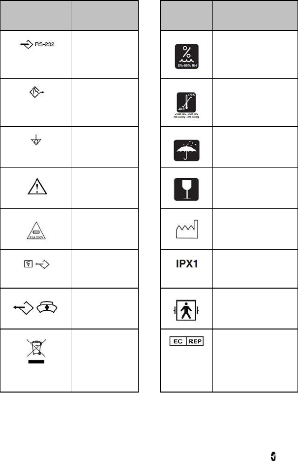
Radical-7 Chapter 8: Specifications
www.masimo.com 126 Masimo
Symbols
The following symbols are found on the Radical-7, Docking Station, or packaging and are
defined below. Some of the interfaces and symbols are not available on all versions of the
Docking Station.
Symbols Definition Symbols Definition
RS-232 interface
Relative humidity
storage range
SatShare interface
Storage temperature
range
Equipotential
ground terminal
Keep dry
See Instructions
for Use
Fragile/breakable,
handle with care
Fuse replacement
Year of Manufacture
Analog Out
interface IPX1 Protection against
liquid drops falling
vertically
Nurse Call
interface
Defibrillation proof type
BF
WEEE Compliant EU authorized
representative
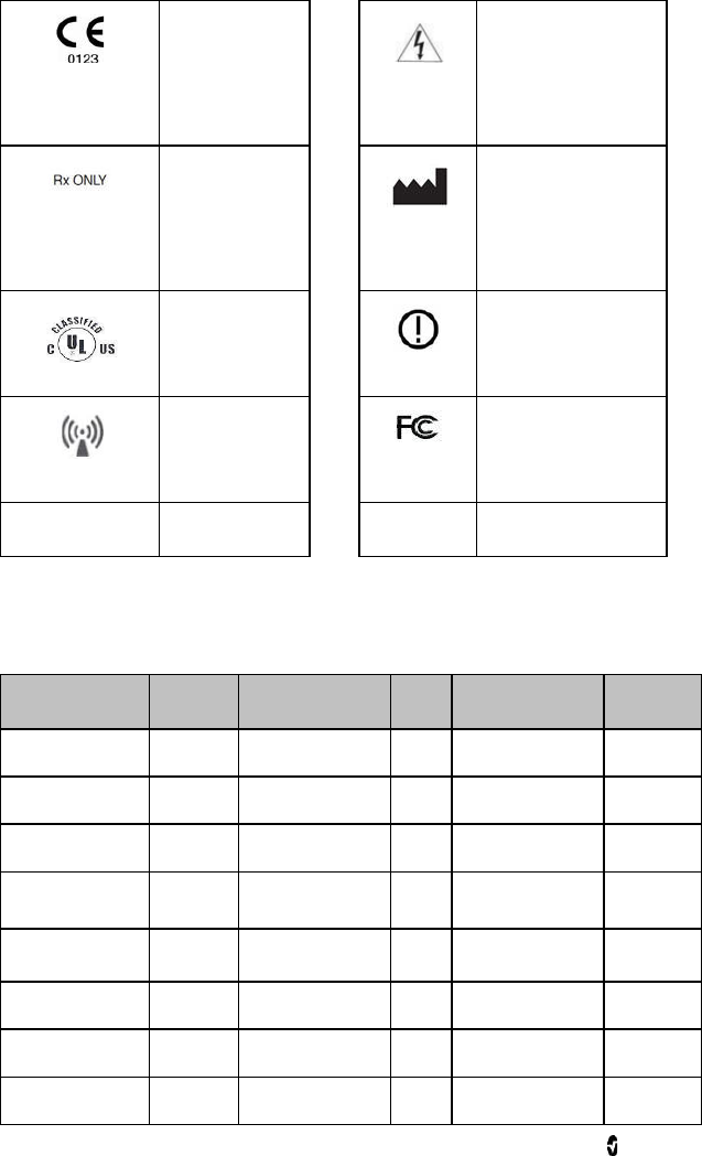
Radical-7 Chapter 8: Specifications
www.masimo.com 127 Masimo
Mark of conformity
to European
Medical
Instrument
Directive
93/42/EEC
Caution
Federal law
restricts this
device to sale by
or on the order of a
physician (USA
FDA)
Name of Manufacturer
Underwriter's
Laboratories Inc.
certification
Wireless features can be
used in member states
with the restriction of
indoor use in France
Non-ionizing
electromagnetic
radiation
Federal
Communications
Commission (FCC)
licensing
IC Model RAD7A
Country Codes (FCC and EU)
This equipment may be operated in the following countries:
Country Code Country Code Country Code
Albania AL Andorra AD Aruba AW
Austria AT Bahamas BS Bahrain BH
Bangladesh BD Belgium BE Brunei BN
Cambodia KH Chile CL Colombia CO
Costa Rica CR Croatia HR Cyprus CY
Czech Republic CZ Denmark DK Ecuador EC
El Salvador SV Estonia EE Finland FI
San Marino SM France FR Germany DE

Radical-7 Chapter 8: Specifications
www.masimo.com 128 Masimo
Ghana GH Greece GR Guatemala GT
Honduras HN Hong Kong HK Hungary HU
India IN Iraq IQ Israel IL
Italy IT Jordan JO Kazakhstan KZ
Kenya KE Kuwait KW Laos LA
Lebanon LB Libya LY Malta MT
Mauritius MU Monaco MC Morocco MA
Mozambique MZ Netherlands NL New Caledonia NC
Nigeria NG Norway NO Oman OM
Palestinian
Territory PS Panama PA Papua New Guinea PG
Peru PE Philippines PH Poland PL
Portugal PT Puerto Rico PR Qatar QA
Republic of Serbia RS Reunion RE Russia RU
Saudi Arabia SA Senegal SN Singapore SG
Slovakia SK Slovenia SI South Africa ZA
Spain ES Sweden SE Thailand TH
Trinidad and
Tobago TT Turkey TR Uganda UG
United Kingdom GB Uruguay UY Vietnam VN

Radical-7 Chapter 8: Specifications
www.masimo.com 129 Masimo
Citations
[1] SpO2, SpCO, and SpMet accuracy was determined by testing on healthy adult volunteers in
the range 60% to 100% SpO2, 0% to 40% SpCO, and 0% to 15% SpMet against a laboratory
CO-Oximeter. SpO2 and SpMet accuracy was determined on 16 neonatal NICU patients ranging
in age from 7 days to 135 days old and weighting between 0.5 kgs and 4.25 kgs. Seventy-nine
(79) data samples were collected over a range of 70% to 100% SaO2 and 0.5% to 2.5% HbMet
with a resultant accuracy of 2.9% SpO2 and 0.9% SpMet. Contact Masimo for testing
specifications.
[2] The Masimo Rainbow SET technology with Masimo sensors has been validated for no
motion accuracy in human blood studies on healthy adult male and female volunteers with
light to dark skin pigmentation in induced hypoxia studies in the range of 70-100% SpO2
against a laboratory CO-Oximeter and ECG monitor. This variation equals plus or minus one
standard deviation which encompasses 68% of the population weight.
[3] The Masimo Rainbow SET technology with Masimo sensors has been validated for motion
accuracy in human blood studies on healthy adult male and female volunteers with light to
dark skin pigmentation in induced hypoxia studies while performing rubbing and touching
motions, at 2 to 4 Hz at an amplitude of 1 to 2 cm and a non-repetitive motion between 1 to 5
Hz at an amplitude of 2 to 3 cm in induced hypoxia studies in the range of 70-100% SpO2
against a laboratory CO-Oximeter and ECG monitor. This variation equals plus or minus one
standard deviation. Plus or minus one standard deviation encompasses 68% of the population.
[4] The Radical-7 has been validated for low perfusion accuracy in bench-top testing against a
Biotek Index 2TM* simulator and Masimo's simulator with signal strengths of greater than
0.02% and transmission of greater than 5% for saturations ranging from 70-100%. This
variation equals plus or minus one standard deviation. Plus or minus one standard deviation
encompasses 68% of the population.
[5] Masimo Rainbow SET technology with Masimo sensors has been validated for pulse rate
accuracy for the range of 25-240 bpm in bench top testing against a Biotek Index 2 simulator.
This variation equals plus or minus one standard deviation which encompasses 68% of the
population.
[6] SpHb accuracy has been validated on healthy adult male and female volunteers and on
surgical patients with light to dark skin pigmentation in the range of 8 g/dL to 17 g/dL SpHb
against a laboratory CO-Oximeter. The variation equals plus or minus one standard deviation
which encompasses 68% of the population. The SpHb accuracy has not been validated with
motion or low perfusion.
[7] This represents approximate run time at the lowest indicator brightness and pulse tone
turned off using a fully charged battery.
[8] If the batteries are to be stored for extended periods of time, it is recommended that they be
stored between -20°C to +30°C, and at a relative humidity less than 85%. If stored for a
prolonged period at environmental conditions beyond these limits, overall battery capacity
may be diminished, and lifetime of the batteries may be shortened.
[9] With FastSat the averaging time is dependent on the input signal. For the 2 and 4 second
settings the averaging time may range from 2-4 and 4-6 seconds, respectively.
[10] Maximum sensitivity mode fixes perfusion limit to 0.02%.
[11] Respiration rate accuracy for the Masimo Acoustic Respiration Sensor and Instrument has
been validated for the range of 4 to 70 breaths per minute in bench top testing. Clinical
validation for up to 30 breaths per minute was also performed with the Masimo Acoustic
Respiration Sensor and Instrument.
*Registered trademark of Fluke Biomedical Corporation, Everett, Washington.

www.masimo.com 131 Masimo
Chapter 9: Service and Maintenance
The following chapter contains information about cleaning, battery operation, performance
verification, service, repair, and warranty.
Cleaning
Under normal operation, no internal adjustment or recalibration is required. Safety tests and
internal adjustments should be done by qualified personnel only. Safety checks should be
performed at regular intervals or in accordance with local and governmental regulations.
Safety Information, Warnings, and Cautions on page 11.
The Radical-7 Pulse CO-Oximeter is a reusable instrument. The instrument is supplied and
used non-sterile.
To surface clean the Radical-7
• The outer surface of the instrument can be cleaned with a soft cloth dampened
with a mild detergent and warm water solution.
• Do not allow liquids to enter the interior of the instrument.
• The outer surface of the instrument can also be wiped down using any of the
following solvents:
• Cidex Plus (3.4% glutaraldehyde)
• 10% bleach solution
• 70% isopropyl alcohol solution
Using the recommended cleaning solutions on the touchscreen panel will not affect the
performance of the Handheld.
Battery Operation and Maintenance
The Radical-7 Handheld includes a lithium ion rechargeable battery. The Radical-7 Docking
Station may include the optional 6.5 amp-hour nickel metal hydride rechargeable battery.
Before using the Radical-7 as a Handheld or as a transport monitor, the Handheld
rechargeable battery and the optional Docking Station rechargeable battery must be fully
charged.
To charge the Handheld rechargeable battery and the Docking Station rechargeable
battery
1. Attach the Handheld to the Docking Station.
2. Connect the Docking Station to AC power.
3. Verify that the batteries are charging.
• The Docking Station Battery Charging indicator momentarily flashes and
then remains illuminated while the batteries are actively charging.
• If the internal battery temperature exceeds recommended operating
conditions for proper battery charging, the Handheld Battery Charging

Radical-7 Chapter 9: Service and Maintenance
www.masimo.com 132 Masimo
indicator continuously flashes. When the temperature returns to
recommended operating conditions, proper battery charging proceeds.
• The Handheld battery requires approximately 4 hours for charging. The
Docking Station battery requires approximately 6 hours for charging.
• When both the Handheld Battery Charging indicator and the Docking Station
Battery Charging indicator turn off, additional trickle charging may occur to
complete charging.
• Memory effects of the battery may shorten run-time. When battery run time
is significantly reduced, it is advisable to completely discharge and fully
recharge the battery. Charging can occur while the Handheld is docked and
turned on, the most efficient charge times are achieved when the Handheld
is turned off.
During battery operation of the Radical-7, note that the following operating conditions affect
the estimated run time of the included rechargeable batteries:
Estimated Run Times of Battery Power
The following tables outline the estimated run times of the battery-powered Radical-7. The
time estimates are based on a Radical-7 with fully charged batteries. The time estimates are
also based on a Radical-7 with and without the back-light illuminated.
The Radical-7 is always configured to include the Handheld battery. It may optionally be
configured to include the Docking Station battery. Determine the configuration of the system
before referencing the following tables.
Run Time for Handheld Only
In this configuration, the Radical-7 is configured to only include the Handheld battery
(standard configuration). When running on battery power, it is advisable to operate only the
Handheld. On battery power, it is possible to operate the Standalone (Handheld attached to
the Docking Station with the Handheld battery providing power to the Docking Station).
However, the capacity of the Handheld battery pack is not sufficient to support this mode for
long periods of time.
For optimal battery run time, configure the device to automatically adjust the brightness. See
Brightness on page 80.
Configuration Operation Mode Minimum run
time
Handheld only Handheld, undocked, not connected to AC power 4 hours
Handheld only Handheld docked, not connected to AC power 1 hour

Radical-7 Chapter 9: Service and Maintenance
www.masimo.com 133 Masimo
Replacing the Batteries
Before installing or removing the battery, make sure the AC power cord is removed and power
to the Radical-7 is turned off.
To replace the rechargeable Handheld battery
1. Turn off the Radical-7 Handheld off and remove the patient cable connection. If
docked, detach the Handheld from the Docking Station.
2. Loosen the closure screw on the battery compartment door and lift out the battery.
3. Take a new battery and place it in the compartment.
4. Tighten the closure screw.
5. Place the Handheld into Docking Station, turn on line power and charge battery.
See Battery Operation and Maintenance on page 131.
Replacing the Fuses
Should a power problem blow one or both of the fuses in the power entry module on the rear
panel, the fuse(s) will need to be replaced. Before starting, the user will need a 5-mm or
3/16-in screwdriver.
To replace the fuse(s)
1. Disconnect instrument from AC power.
2. Remove AC power cord from the power entry module at the rear of the Docking
Station.
3. Using the screwdriver, gently pry loose the fuse cover in the left portion of the
power entry module, exposing the fuse holder.
4. Using the screwdriver, gently remove the fuse holder.
5. Note how the fuse(s) are placed in the fuse holder for installation of the new
fuse(s).
6. To remove the fuses from the fuse holder, use the edge of the screwdriver blade to
pry against the bottom of the metal portion of the fuse where it is secured to the
glass portion of the fuse.
7. Place the fuse(s) (1 amp, metric, fast-acting, 5x20mm, 250V) in the fuse holder,
properly orienting the fuse(s).
8. Slide the fuse holder back into the power entry module and press firmly to make
sure it is completely seated.
9. Close the fuse cover and press gently until it seats completely, flush with the back
of the Docking Station.
The instrument is ready to be reconnected to AC power. If the fuses blow shortly
after replacement, the instrument requires service.

Radical-7 Chapter 9: Service and Maintenance
www.masimo.com 134 Masimo
Performance Verification
Under normal operation, no internal adjustment or recalibration is required. Safety tests and
internal adjustments should be done by qualified personnel only. Safety checks should be
performed at regular intervals or in accordance with local and governmental regulations.
To test the performance of the Radical-7 following repairs or during routine maintenance,
follow the procedure outlined in this chapter. If the Radical-7 fails any of the described tests,
discontinue its use and correct the problem before returning the instrument back to the user.
Before performing the following tests, do the following:
• Place the Handheld into the Docking Station.
• Connect the Docking Station to AC power and fully charge the Handheld battery.
• Disconnect any patient cables or pulse oximetry probes.
• Disconnect any SatShare, serial or analog output cables from the instrument.
• Set the Radical-7 to Normal operating mode by going to the Main menu and the
Home Use feature to No.
Power-On Self Test
To conduct a Power-On Self Test
1. Connect the monitor to the AC power and verify that the AC Power indicator is
illuminated.
2. Turn on the monitor. Within 5 seconds, all available indicators illuminate, the
instrument emits a tone and the Masimo logo displays.
3. The Docking Station indicator continuously illuminates and the Radical-7 begins
normal operation.
Alarm Limit Test
To conduct an Alarm Limit Test
1. Change the High SpO2 Alarm parameter to a value two points below the currently
selected value. See Alarms for SpO2 on page 62.
2. Verify that the newly set parameter is shown on the Display screen.
3. Return the parameter to its original setting.
4. Repeat steps 1 to 3 for all active parameters.
5. Reset the alarm limits again to the original settings.
Testing with the optional Masimo SET Tester
To conduct a test with the optional Masimo SET Tester
1. Turn off and then turn on the Radical-7.
2. Use the Patient Cable connector on the Radical-7 to connect the Masimo SET
Tester to the Radical-7.
3. See the directions for use that were provided with the Masimo SET Tester.

Radical-7 Chapter 9: Service and Maintenance
www.masimo.com 135 Masimo
Nurse Call Test
To conduct a Nurse Call test
1. Disconnect any patient cables, sensors, or accessories from the Radical-7. Turn off
the Radical-7 and then turn on again.
2. Ensure that there are no audible alarms and that the Audible Alarm feature is not
set to silenced.
3. Verify the Nurse Call polarity is set to normal (default).
4. Connect the common lead of a digital multi-meter to the pin 12 (Nurse Call
Common) of the Analog Output connector on the Radical-7. Connect the positive
lead of the multi-meter to pin 6 (Nurse Call - Normally Open) of the Analog Output
connector and measure that the resistance is greater than 1 MW (open circuit).
5. Trigger an alarm on the monitor (for example, by disconnecting a sensor after it
was measuring data). Verify that the resistance is less than 35 ohms.
Analog Output Test
To conduct an Analog Output test
1. Disconnect any patient cables, sensors, or accessories from the Radical-7. Turn off
the Radical-7 and then turn on again.
2. Connect the common lead of a digital voltmeter to the pin 2 (Ground) of the
analog output connector on the Radical-7. Connect the positive lead of the
voltmeter to pin 9 (Analog 1) of the analog output connector.
3. On the device output screen, on the analog 1 option, select 0V Output. See Device
Output on page 80.
4. Verify that the voltmeter measures a voltage of approximately 0V.
5. Change the analog 1 option to 1V Output.
6. Verify that the voltmeter measures a voltage of approximately 1.0V.
7. Repeat steps 5 and 6, with the positive lead of the voltmeter connected to pin 15
(analog 2). See Serial Interface Specifications on page 122.
8. Connect a patient cable and sensor and verify that the voltage on pins 9 and 15
are between 0V and 1.0V while measuring a saturation and pulse rate.
Battery Test
To conduct a Battery test
1. Fully charge the Radical-7 by placing the Handheld into the Docking Station and
then connect the AC power.
2. Verify that the Handheld Battery Charging indicator is illuminated.
3. When the Radical-7 is fully charged, the Handheld Battery Charging indicator
turns off.
4. Turn on the Radical-7 on and verify that the Battery indicator shows a full charge.

Radical-7 Chapter 9: Service and Maintenance
www.masimo.com 136 Masimo
Repair Policy
Masimo or an authorized Service Department must perform warranty repair and service. Do
not use malfunctioning equipment. Have the instrument repaired.
Clean contaminated and/or dirty equipment before returning, following the cleaning
procedure described in Cleaning. Make sure the equipment is fully dry before packing.
To return the instrument for service, see Return Procedure on page 136.
Return Procedure
Clean contaminated/dirty equipment before returning, following instructions in Cleaning on
page 131. Make sure the equipment is fully dry before packing. Call Masimo at 800-326-4890
and ask for Technical Support. Ask for an RMA number. Package the equipment securely, in
the original shipping container if possible, and enclose or include the following information
and items:
• A letter describing in detail any difficulties experienced with the Radical-7. Include
the RMA number in the letter.
• Warranty information, a copy of the invoice or other applicable documentation
must be included.
• Purchase order number to cover repair if the Radical-7 is not under warranty, or for
tracking purposes if it is.
• Ship-to and bill-to information.
• Person (name, telephone/Telex/fax number, and country) to contact for any
questions about the repairs.
• A certificate stating the Radical-7 has been decontaminated for bloodborne
pathogens.
• Return the Radical-7 to the shipping address listed in Contacting Masimo on page
136.
Contacting Masimo
To contact Masimo, refer to the following:
USA, Canada, and Asia Pacific Europe All Other Locations
Masimo Corporation
40 Parker
Irvine, California 92618
(949) 297-7000
Fax: (949) 297-7001
Masimo International Sàrl
Puits-Godet 10
2000 Neuchatel-
Switzerland
Tel:+41 32 720 1111
Fax: +41 32 724 1448
Contact your local Masimo
Representative.

Radical-7 Chapter 9: Service and Maintenance
www.masimo.com 137 Masimo
Warranty
Masimo warrants to the initial Purchaser for a period of one (1) year from the date of purchase
that: (i) each new Product and the Software media as delivered are free from defects in
workmanship or materials, and (ii) the Product and Software will perform substantially as
labeled in the directions for use. Masimo’s sole obligation under this warranty is to repair or
replace any Product or Software that is covered under warranty.
Batteries are warranted for six (6) months.
To request a replacement under warranty, Purchaser must contact Masimo for a returned
goods authorization. If Masimo determines that a Product must be replaced under warranty,
it will be replaced and the cost of shipment covered. All other shipping costs shall be the
responsibility of Purchaser.
Exclusions
The warranty does not extend to, and Masimo is not responsible for, repair, replacement, or
maintenance needed because of: a) modification of the Product or Software without Masimo’s
written authorization; b) supplies, instruments or electrical work external to the Product or
not manufactured by Masimo; c) disassembly or reassembly of the Product by anyone other
than an authorized Masimo agent; d) use of the Product with sensors or other accessories
other than those manufactured and distributed by Masimo; e) use of the Product and
Software in ways or in environments for which they are not labeled; and f) neglect, misuse,
improper operation, accident, fire, water, vandalism, weather, war, or any act of God. This
warranty does not extend to any Product that has been reprocessed, reconditioned or
recycled.
This warranty also does not apply to any Products provided to Purchaser for testing or
demonstration purposes, any temporary Products modules or any Products for which Seller
does not otherwise receive a usage or purchase fee; all such Products are provided AS-IS
without warranty.
This warranty, together with any other express written warranty that may be issued by
masimo is the sole and exclusive warranty as to the product and software. this warranty is
expressly in lieu of any oral or implied warranties, including without limitation any implied
warranty of merchantability or fitness for a particular purpose. masimo shall not be liable for
any incidental, special or consequential loss, damage or expense directly or indirectly arising
from the use or loss of use of any products or software. in no event shall masimo’s liability
arising from any product and software (under contract, warranty, tort, strict liability or other
claim) exceed the amount paid by purchaser for the products giving rise to such claim. the
limitations in this section shall not be deemed to preclude any liability that cannot legally be
disclaimed by contract.
Sales & End-User License Agreement
This document is a legal agreement between you (“purchaser”) and Masimo corporation
(“Masimo”) for the purchase of this product (“product”) and a license in the included or
embedded software (“software”) except as otherwise expressly agreed in a separate contract
for the acquisition of this product, the following terms are the entire agreement between the
parties regarding your purchase of this product. if you do not agree to the terms of this
agreement, promptly return the entire product, including all accessories, in their original
packages, with your sales receipt to masimo for a full refund.

Radical-7 Chapter 9: Service and Maintenance
www.masimo.com 138 Masimo
Restrictions
1. Copyright Restrictions: The Software and the accompanying written materials are
copyrighted. Unauthorized copying of the Software, including Software that has
been modified, merged, or included with other software, or the written materials is
expressly forbidden. Purchaser may be held legally responsible for any copyright
infringement that is caused or incurred by Purchaser’s failure to abide by the terms
of this Agreement. Nothing in this License provides any rights beyond those
provided by 17 U.S.C. §117.
2. Use Restrictions: Purchaser may physically transfer the Product from one location
to another provided that the Software is not copied. Purchaser may not
electronically transfer the Software from the Product to any other instrument.
Purchaser may not disclose, publish, translate, release, distribute copies of, modify,
adapt, translate, reverse engineer, decompile, disassemble, or create derivative
works based on the Software or the written materials.
3. Transfer Restrictions: In no event may Purchaser transfer, assign, rent, lease, sell,
or otherwise dispose of the Product or the Software on a temporary basis.
Purchaser shall not assign or transfer this License, in whole or in part, by operation
of law or otherwise without Masimo's prior written consent; except that the
Software and all of Purchaser’s rights hereunder shall transfer automatically to any
party that legally acquires title to the Product with which this Software is included.
Any attempt to assign any rights, duties or obligations arising hereunder other
than as set forth in this paragraph shall be void.
4. U.S. Government Rights: If Purchaser is acquiring Software (including the related
documentation) on behalf of any part of the United State Government, the
following provisions apply: the Software and documentation are deemed to be
“commercial software” and “commercial computer software documentation,”
respectively pursuant to DFAR Section 227.7202 FAR 12.212, as applicable. Any
use, modification, reproduction, release, performance, display or disclosure of the
Software (including the related documentation) by the U.S. Government or any of
its agencies shall be governed solely by the terms of this Agreement and shall be
prohibited except to the extent expressly permitted by the terms of this
Agreement.

www.masimo.com 139 Masimo
Appendix: Best Practices for
Comparisons to Reference
Measurements
Best Practices Checklist for Continuous SpHb Comparisons
Ensure SpHb device is turned on. If applicable, connect to computer with automatic
data capture.
Sensor site selection:
• Remove anything from patient's arm that can impede blood flow to the
sensor site, such as restrictive garments, accessories, purses, backpacks,
watches, jewelry, and blood pressure cuff.
• Do not use sites with any of the following conditions:
An anatomically abnormal finger (e.g. damaged, clubbed, deviated, etc.).
A finger or arm that has experienced previous surgical procedures.
A finger or arm that is currently receiving an IV infusion.
A finger or arm that is currently used for blood pressure cuff.
• Site should be cleaned of debris and dry prior to testing.
• Nail polish should be removed prior to testing.
• Select the patient’s testing finger in the following priority:
Non-dominant ring or middle finger.
Dominant ring or middle finger.
Sensor selection:
• For reusable sensors, measure the patient's finger size (diameter) at the
cuticle, using the sensor size gauge, to determine the correct sensor size.
• When using ReSposable sensors, connect the reusable optical sensor (ROS)
to the disposable optical sensor (DOS) after DOS properly placed onto finger.
Ensure proper sensor positioning:
• Rest patient’s hand and arm with sensor on a horizontal surface securely to
limit the movement of the patient.
• Examine the finger while placed in the sensors to ensure the emitter and
detector are directly aligned on top of each other and there is no gap
between the sensor and fingertip.
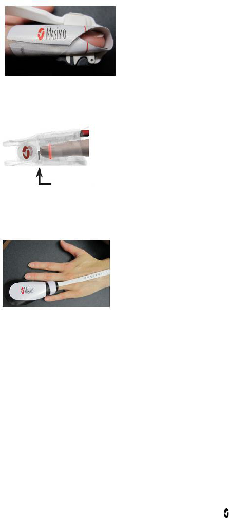
Radical-7 Appendix: Best Practices for Comparisons to Reference Measurements
www.masimo.com 140 Masimo
• Align upper and lower red lines.
• If using a reusable sensor, make sure finger tip is inserted all the way and
touching the finger stop inside the sensor (allowing long finger nails to
extend beyond the finger stop).
• Ensure cable runs flat over the top of the hand directly in the middle of the
finger with no kinks or twists so the cable does not pull on the sensor.
• Cover sensor with Masimo-provided shielding to avoid light interference.

Radical-7 Appendix: Best Practices for Comparisons to Reference Measurements
www.masimo.com 141 Masimo
• Secure sensor cable to patient’s arm with tape.
• Instruct subjects to remain still without any sensor movement.
• Connect sensor cable to device without pulling on sensor.
• Wait until SpHb measurement is stable (one minute) before recording SpHb
values.
• Note any Low SIQ message that displays during measurement.
Blood sampling and laboratory analysis:
• Record site of blood draw.
• Document exact time blood withdrawn from patient.
• When taking blood sample from arterial line, remove adequate dead space to
ensure blood sample is not diluted with solution to keep arterial line open.
When IV line set-up includes stopcocks, ensure that no fluid is infused
through the line from which you are taking the blood. Draw blood directly
into the vacutainer, if possible.
• Mix blood carefully after filling the vacutainer by rotating it gently at least 10
times. (A rotation is one turn of the tube upside down and then right side
up.)
• All blood samples must be analyzed on the same calibrated laboratory
hematology analyzer (Coulter, Sysmex, or equivalent) to avoid variation
induced by the use of multiple laboratory devices.

Radical-7 Appendix: Best Practices for Comparisons to Reference Measurements
www.masimo.com 142 Masimo
Best Practices Checklist for SpCO Comparisons
Ensure SpCO device is powered on and connected to computer with automatic data
capture.
After venous blood draw, SpCO testing must be initiated within 30 seconds (COHb can
change rapidly).
Sensor site selection:
• Remove anything from patient's arm that can impede blood flow to the
sensor site, such as restrictive garments, accessories, purses, backpacks,
watches, jewelry, and blood pressure cuff.
• Do not use sites with any of the following conditions:
An anatomically abnormal finger (e.g. damaged, clubbed, deviated, etc.).
A finger or arm that has experienced previous surgical procedures.
A finger or arm that is currently receiving an IV infusion.
A finger or arm that currently used for blood pressure cuff.
• Site should be cleaned of debris and dry prior to testing.
• Nail polish should be removed prior to testing.
• Select the patient’s testing finger in the following priority:
Non-dominant ring or middle finger.
Dominant ring or middle finger.
Sensor selection:
• Use the appropriate sensor as defined in the sensor directions for use.
Ensure proper sensor positioning:
• Rest patient’s hand and arm with sensor on a horizontal surface securely to
limit the movement of the patient.
• Examine the finger while placed in the sensors to ensure the emitter and
detector are directly aligned on top of each other and there is no gap
between the sensor and fingertip.
• Align upper and lower red lines.
• If using a reusable sensor, make sure finger tip is inserted all the way and
touching the finger stop inside the sensor (allowing long finger nails to
extend beyond the finger stop).
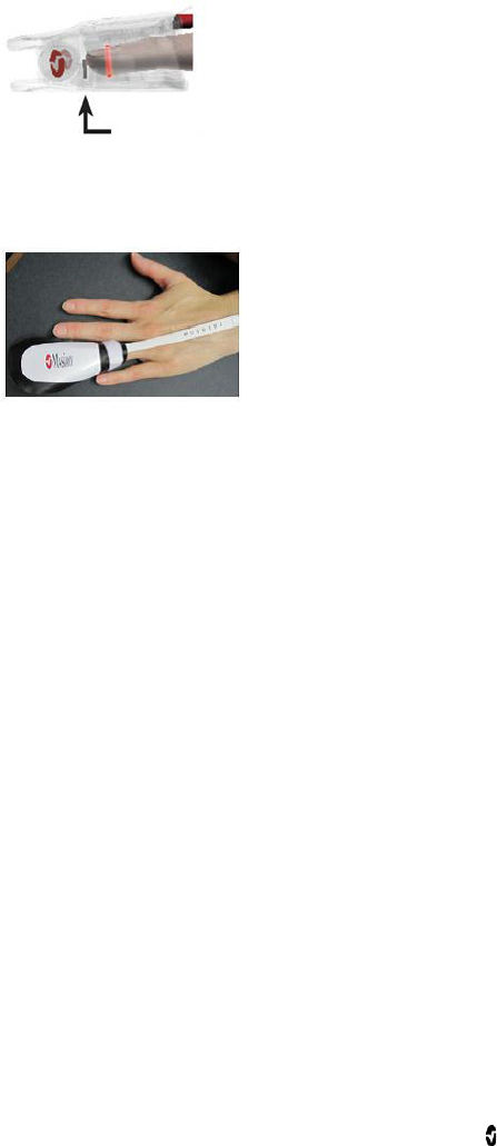
Radical-7 Appendix: Best Practices for Comparisons to Reference Measurements
www.masimo.com 143 Masimo
• Ensure cable runs flat over the top of the hand directly in the middle of the
finger with no kinks or twists so the cable does not pull on the sensor.
• Cover sensor with Masimo-provided shielding to avoid light interference.
• Secure sensor cable to patient’s arm with tape.
• Instruct subjects to remain still without any sensor movement.
• Connect sensor cable to device without pulling on sensor.
• Wait until SpCO measurement is stable (one minute) before recording SpHb
values.
Note any Low SIQ messages that display during measurement.
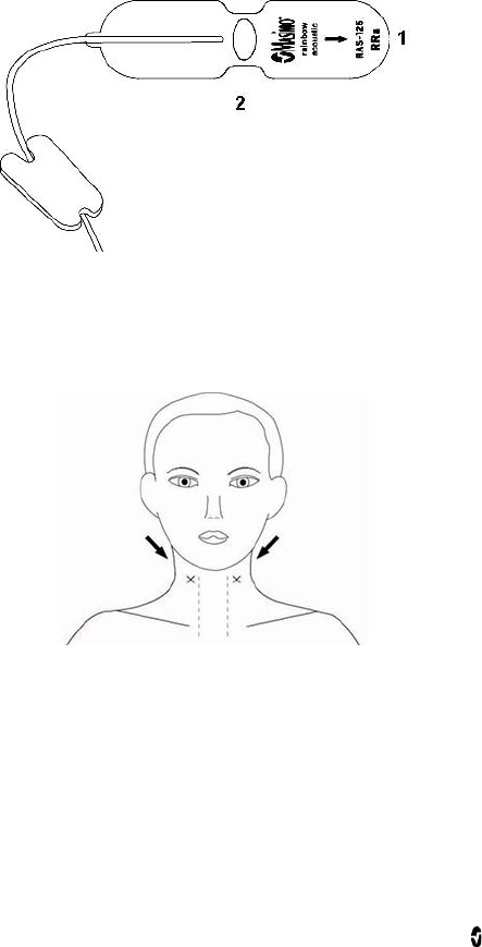
Radical-7 Appendix: Best Practices for Comparisons to Reference Measurements
www.masimo.com 144 Masimo
Best Practices Checklist for Acoustic Respiration Rate
Comparisons
Acoustic Sensor placement
The Acoustic sensor has a small black arrow on the front (item 1 in figure below), when
placing the sensor the black arrow should point forward to the anterior of subject’s body.
Ensure placement site is hair-free, clean of debris, and dry prior to sensor placement.
Use an alcohol swab to clean the neck area, if needed.
The sensor pad (item 2 in the figure above) should be placed to either side of the larynx,
in the area just above the thyroid cartilage and below the jaw line (see figure below). Ensure
that there are no skin folds under the sensor pad.

Radical-7 Appendix: Best Practices for Comparisons to Reference Measurements
www.masimo.com 145 Masimo
For pediatric subjects that have limited neck space, the sensor may be placed on the
right side of chest, underneath clavicle. The sensor should not be touching the clavicle.
Place sensor tape on skin. Gently press on sensor tape from center outward so adhesive
forms a good contact with patient's skin. Ensure there are no skin folds or air gaps under
sensor pad.
Remove the release liner from the anchor pad and place the anchor pad on patient’s side
of the neck; route the sensor cable in front of patient. Do not place anchor pad on clothing.
Pulse-Oximeter Sensor Placement
Place finger sensor on middle or ring finger of hand opposite the blood pressure cuff.
For reusable sensors, make sure the fingertip just touches the rubber stopper at the end
of the sensor without going over it.
Ensure sensor is right side up with the cable running in line with finger, not at an angle
on dorsal (back side) of hand.
Monitoring
Ensure RRa device is turned on and connected to computer with automatic data capture.
Connect sensor to cable.
If RRa values are not displayed after 2 minutes or if the RRa value has dropped out,
check the following:
• Confirm appropriate sensor placement, orientation and site selections.
• Confirm that optical pulse-oximeter sensor is placed properly on the
patient's finger.
• Confirm that all cables are plugged in at each of the various connection
points and hubs.
• Auscultate with stethoscope to listen for air sounds on the side opposite
sensor. If breath sounds are present, remove sensor and replace with new
sensor on opposite side of neck.
• Change the sensor out if RRa value continues to not display.
• Verify that there is not excessive hair or a gap between the sensor and the
neck and that it is placed.
Simultaneously record the RRa and respiratory rates and from other methods. If
comparing RRa to capnography respiration rate, a mask is recommended. Sidestream
methods with a nasal cannula are not recommended because of dilution effect in the
supplemental flow of gasses, inability to measure both nasal and oral airflow, and nasal
cannula mispositioning. When recording values, confirm that there are no SIQ messages
displayed on the device.
Suggested directions to record manual respiration rate are as follows:
• Use stethoscope to listen for breath sounds, count each breath cycle as one
breathe, count for 60 seconds.
• Alternate method to stethoscope, count the number of chest
rises/inhalations during a 60 second period. Record manual respiration rate
to compare with RRa.

Radical-7 Appendix: Best Practices for Comparisons to Reference Measurements
www.masimo.com 146 Masimo
Adjust respiratory pause settings as necessary, default is 30 seconds (options are: 15,
20, 25, 30, 35, or 40 seconds).
Document patient events and time of event (based on computer clock). Include events
that may affect performance, these include:
• Patient talking, picking at the sensor or nasal cannula, excessive movement,
ambient noise present, fans or air blowing at sensor
Inaccurate measurements may be caused by:
• Excessive ambient or environmental noise (patient speaking, room noise)
• Improper sensor placement
• Cable disconnection
• Movement, picking, or air blowing at sensor

Radical-7 Appendix: Best Practices for Comparisons to Reference Measurements
www.masimo.com 147 Masimo

www.masimo.com 149 Masimo
Index
3
3D Alarms • 58, 102
A
About • 58, 91
About Alarms • 99, 101
About Parameter Information • 60, 62,
63, 65, 66, 69, 70, 71, 72, 73, 91, 102,
103
About the Display View • 45, 48
About the Status Bar • 48, 49, 79, 80, 111
About this Manual • 7
About Trend Views • 81
Access Control • 46, 74, 75, 76, 94, 97
Accessing the Main Menu • 47, 49, 57
Accuracy • 115
Acoustic Waveform View • 54
Acquisition System • 30
Adaptive Threshold Alarm (ATA) Feature
• 62, 101
Additional Settings for PI • 66
Additional Settings for PVI • 70, 71
Additional Settings for RRa • 69, 70
Additional Settings for RRp • 67, 68
Additional Settings for SpHb • 63, 64
Additional Settings for SpO2 • 62, 63
Alarm Limit Test • 134
Alarm Related Safety Information,
Warnings, and Cautions • 20, 99
Alarms • 119
Alarms for SpO2 • 62, 101, 134
Analog Output and Nurse Call
Specifications • 124
Analog Output Test • 135
Appendix
Best Practices for Comparisons to
Reference Measurements • 112, 113,
139
B
Battery • 49, 75, 80
Battery Operation and Maintenance • 36,
42, 44, 80, 114, 131, 133
Battery Run Time Significantly Reduced •
114
Battery Test • 135
Best Practices Checklist for Acoustic
Respiration Rate Comparisons • 144
Best Practices Checklist for Continuous
SpHb Comparisons • 139
Best Practices Checklist for SpCO
Comparisons • 142
Brightness • 75, 80, 113, 132
Buttons Do Not Work When Pressed • 114
C
Changing Between Trend Views • 82, 86
Changing Profiles • 56, 58, 94
Changing Sensitivity Modes • 56
Changing the Size of Parameter Values •
35, 48, 50
Changing the Time Interval of Trend
Data • 85
Changing Trend Settings • 88
Chapter 1
Technology Overview • 23
Chapter 2
Radical-7 Descriptions • 33
Chapter 3
Setup • 41
Chapter 4
Operation • 45
Chapter 5
Profiles • 35, 45, 93
Chapter 6
Alarms and Messages • 99, 112, 113
Chapter 7

Radical-7 Index
www.masimo.com 150 Masimo
Troubleshooting • 99, 111
Chapter 8
Specifications • 115
Chapter 9
Service and Maintenance • 107, 131
Citations • 129
Cleaning • 131, 136
Compliance • 121
Contacting Masimo • 113, 114, 136
Continuous Speaker Tone • 114
Contraindications • 10
Country Codes (FCC and EU) • 127
D
Deleting Trend Data • 90
Desat Index Alarm Overview • 102, 103
Desat Index Alarms • 102, 103
Desat Index Settings • 102
Device Output • 44, 75, 80, 135
Device Related Safety Information,
Warnings, and Cautions • 14, 42, 43,
44
Device Settings • 57, 75, 106, 123
Difficulty Obtaining a Reading • 113
Dimly Lit Parameters • 112
Display Indicators • 120
Docking Station Power Requirements •
41
E
Electrical • 117
Electrical Safety Information, Warnings,
and Cautions • 18, 42
Environmental • 41, 118
Estimated Run Times of Battery Power •
132
Exclusions • 137
F
FastSat Overview • 63
Functional Oxygen Saturation • 24
Functionality of the Radical-7 • 34
G
General Description for
Carboxyhemoglobin (SpCO) • 28
General Description for Methemoglobin
(SpMet) • 28
General Description for Oxygen
Saturation (SpO2) • 24
General Description for Perfusion Index
(PI) • 25
General Description for Pleth Variability
Index (PVI) • 25
General Description for Pulse Rate (PR) •
25
General Description for SpOC • 28
General Description for Total Arterial
Oxygen Content (CaO2) • 27
General Description for Total
Hemoglobin (SpHb) • 27
General System Description • 33
H
Handheld • 35
Handheld Back Panel • 36
Handheld Battery Does Not Charge • 114
Handheld Front Panel • 35, 124
I
In Vivo Adjustment Overview • 61, 63,
65, 72
In Vivo for SpCO • 61, 72
In Vivo for SpHb • 61, 65
In Vivo for SpMet • 61, 73
In Vivo for SpO2 • 61, 63
Incompatible Adhesive Sensor Message •
105
Incompatible Cable Message • 109
Incompatible Sensor Message • 105
Indications for Use • 10

Radical-7 Index
www.masimo.com 151 Masimo
Indicators on Docking Station
Continuously Flash • 114
Initial Battery Charging • 42
Instrument Does Not Turn On • 113
Instrument Turns On But Screen is Blank
• 113
Interference Detected Message • 106
K
Key Features • 9
L
Localization • 49, 75, 78, 113
Low Battery Message • 106
Low Perfusion • 106, 112
Low Perfusion Index Message • 106
Low Signal IQ Message • 107
Low Signal Quality • 112
Low SpCO SIQ Message • 107
Low SpHb SIQ Message • 107
Low SpMet SIQ Message • 107
M
Manipulating Trend Data • 84
Masimo rainbow SET Parallel Engines •
23
Masimo SET DST • 24
Measurement Range • 115
Messages • 49, 104
Monitor Interface With SatShare • 40
N
Navigating the Main Menu • 57
Navigating the Radical-7 • 47
No Adhesive Sensor Connected Message
• 106
No Cable Connected Message • 107
No Sensor Connected Message • 108
Nurse Call Test • 124, 135
O
Output Interface • 122
P
Parameter Quick Trend View • 55
Parameter Related Safety Information,
Warnings, and Cautions • 11, 111
Parameter Settings • 58, 59
Patient • 30
Performance Verification • 134
Perfusion Index (PI) Delta Alarm
Overview • 102, 103, 104
Perfusion Index (PI) Settings • 59, 66
Physical Characteristics • 118
PI Alarms • 66
PI Delta Alarms • 104
PI Delta Settings • 103
Pleth + Sig IQ + Acoustic View • 54
Pleth + Sig IQ View • 53
Powering Off the Radical-7 • 98
Power-On Self Test • 134
PR Alarms • 65
PR Settings • 59, 65
Product Description • 9
Product Description, Indications for Use,
Contraindications, and Features • 9
Profiles Overview • 49, 93, 97
Pulse Bar • 52
Pulse CO-Oximetry vs. Drawn Whole
Blood Measurements • 26
Pulse Search Message • 108
PVI Alarms • 70
PVI Settings • 59, 70
R
rainbow Acoustic Monitoring (RAM)
Technology • 29, 67
rainbow Acoustic Monitoring
Architecture • 29

Radical-7 Index
www.masimo.com 152 Masimo
rainbow Pulse CO-Oximetry Technology •
25
Repair Policy • 136
Replace Adhesive Sensor Message • 105
Replace Cable Message • 105
Replace Sensor Message • 104
Replacing Factory Default Settings for
Adult and Neo Profiles • 97
Replacing the Batteries • 133
Replacing the Fuses • 113, 133
Resolution • 117
Respiration Rate (RR) • 59, 67
Restrictions • 138
Return Procedure • 41, 136
RRa Alarms • 69
RRa Settings • 69
RRp Alarms • 67
RRp Settings • 67
Run Time for Handheld Only • 132
S
Safety Information, Warnings, and
Cautions • 11, 27, 28, 29, 41, 99, 131
Sales & End-User License Agreement •
137
Screen Orientation • 75, 79
Sensitivity Modes Overview • 49, 55, 96
Sensor • 30
Sensor Initializing Message • 108
Sensor Off Patient Message • 108
Sensor Related Safety Information,
Warnings, and Cautions • 21
Serial Interface Setup • 123
Serial Interface Specifications • 39, 42,
43, 44, 122, 135
Setting Up and Using SatShare • 40, 44
Setting Up for Philips, Agilent, or HP
VueLink • 42
Setting Up for SpaceLabs Flexport • 43
Setting Up the Docking Station • 41
Signal Extraction Technology (SET) • 23
Signal IQ (SIQ) • 107, 111
Signal IQ Indicators • 52, 53
Signal Processing • 31
Silencing the Alarms • 35, 45, 97, 99
Sounds • 49, 58, 74, 77, 100
SpCO Alarms • 71
SpCO Reading Displays as Dashes • 113
SpCO Settings • 59, 71
SpCO, SpMet, and SpHb Measurements
During Patient Motion • 29
Speaker Failure Message • 107
SpHb Alarms • 63, 64
SpHb Settings • 59, 63
SpMet Alarms • 72
SpMet Settings • 59, 72
SpO2 Only Mode Message • 106
SpO2 Settings • 59, 62
SpO2 Values Do Not Correlate With
Clinical Assessment or Arterial Blood
Gas Measurements • 112
SpOC Alarms • 59, 73
SpOC Settings • 73
Standalone • 37
Standalone Back Panel • 39, 44, 80
Standalone Front Panel • 38, 42
Successful Monitoring for SpCO • 28, 107
Successful Monitoring for SpHb • 27, 107
Successful Monitoring for SpMet • 29
Successful Monitoring for SpO2, PR, and
PI • 24
Symbols • 126
T
Testing with the optional Masimo SET
Tester • 134
Trend Field • 51, 58
Trending • 118
Trends • 51, 58, 81
Troubleshooting Measurements • 27, 111

Radical-7 Index
www.masimo.com 153 Masimo
Troubleshooting the Radical-7 • 113
U
Unexpected SpO2, SpCO, SpMet, or SpHb
Reading • 112
Unexpectedly High SpCO Reading • 113
Unpacking and Inspection • 41
Using Screen Lock • 46
Using the Histogram Feature • 86
Using the Home Button • 46
Using the Touchscreen and Buttons • 45
W
Warranty • 137
Waveform and Trend Views • 48, 52
WiFi • 49, 75, 79
Wireless Radio (If Installed) • 122

www.masimo.com
35196/LAB-5476C 0912