Masimo RADIUS Radius-7 User Manual Radius 7 Operator s Manual CE LAB 8303B
Masimo Corporation Radius-7 Radius 7 Operator s Manual CE LAB 8303B
UserManual.wiki
>
Masimo
>
RADIUS User Manual
User Manual
Navigation menu
Upload a User Manual
Namespaces
Wiki Guide
HTML
PDF
Info
Views
User Manual
Discussion / Help
Navigation
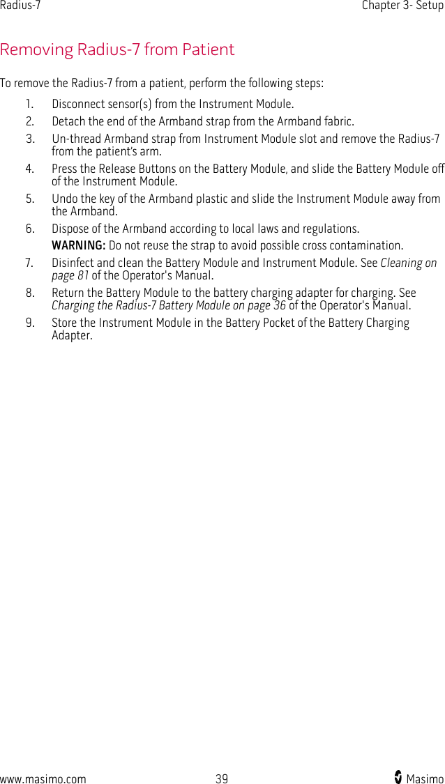
![Radius-7 Chapter 1- Technology Overview www.masimo.com 23 Masimo The Radius-7 uses a multi-wavelength sensor to distinguish between oxygenated blood, deoxygenated blood, blood with carbon monoxide, oxidized blood and blood plasma. The Radius-7 utilizes a sensor with various light-emitting diodes (LEDs) that pass light through the site to a diode (detector). Signal data is obtained by passing various visible and infrared lights (LEDs, 500 to 1400nm) through a capillary bed (for example, a fingertip, a hand, a foot) and measuring changes in light absorption during the blood pulsatile cycle. This information may be useful to clinicians. The maximum radiant power of the strongest light is rated at ≤ 25 mW. The detector receives the light, converts it into an electronic signal and sends it to the Radius-7 for calculation. 1. Light Emitting Diodes (LEDs) (7 + wavelengths) 2. Detector Once the Radius-7 receives the signal from the sensor, it utilizes proprietary algorithms to calculate the patient’s functional oxygen saturation (SpO2 [%]), blood levels of carboxyhemoglobin (SpCO [%]), methemoglobin (SpMet [%]), total hemoglobin concentration (SpHb [g/dL]) and pulse rate (PR). The SpCO, SpMet and SpHb measurements rely on a multi-wavelength calibration equation to quantify the percentage of carbon monoxide and methemoglobin and the concentration of total hemoglobin in arterial blood. The maximum skin surface temperature is measured to be less than 41 º C (106º F) in a minimum 35 º C (95 º F) ambient. This is verified by Masimo sensor skin temperature test procedures. General Description for Total Hemoglobin (SpHb) Pulse CO-Oximetry is a continuous and non-invasive method of measuring the levels of total hemoglobin (SpHb) in arterial blood. It relies on the same principles of pulse oximetry to make its SpHb measurement.](https://usermanual.wiki/Masimo/RADIUS/User-Guide-2594625-Page-23.png)
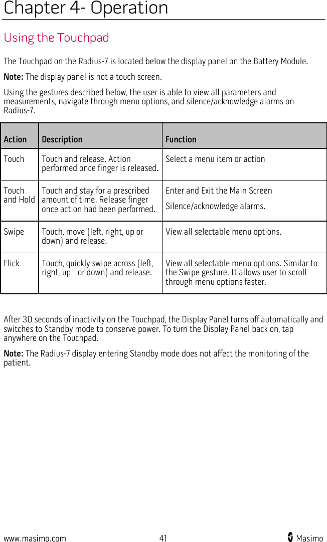
![Radius-7 Chapter 1- Technology Overview www.masimo.com 25 Masimo rainbow Acoustic Monitoring™ (RAM™) rainbow Acoustic Monitoring (RAM) continuously measures a patient’s respiration rate based on airflow sounds generated in the upper airway. The Acoustic Sensor, which is applied on the patient's neck, translates airflow sounds generated in the upper airway to an electrical signal that can be processed to produce a respiration rate, measured as breaths per minute. Respiratory sounds include sounds related to respiration such as breath sounds (during inspiration and expiration), adventitious sounds, cough sounds, snoring sounds, sneezing sounds, and sounds from the respiratory muscles [1]. These respiratory sounds often have different characteristics depending on the location of recording [2] and they originate in the large airways where air velocity and air turbulence induce vibration in the airway wall. These vibrations are transmitted, for example, through the lung tissue, thoracic wall and trachea to the surface where they may be heard with the aid of a stethoscope, a microphone or more sophisticated devices. rainbow Acoustic Monitoring Architecture The following figure illustrates how a respiratory sound produced by a patient can be turned into a numerical measurement that corresponds to a respiratory parameter. Patient Sensor Acquisition System Respiratory airflow to sound Sound to electrical signal Electrical signal to digital signal Signal Processing Envelope Detection RRa Estimation Digital signal to respiratory measurement Patient The generation of respiratory sounds is primarily related to turbulent respiratory airflow in upper airways. Sound pressure waves within the airway gas and airway wall motion contribute to the vibrations that reach the body surface and are recorded as respiratory sounds. Although the spectral shape of respiratory sounds varies widely from person to person, it is often reproducible within the same person, likely reflecting the strong influence of individual airway anatomy [2-6].](https://usermanual.wiki/Masimo/RADIUS/User-Guide-2594625-Page-25.png)
![Radius-7 Chapter 1- Technology Overview www.masimo.com 26 Masimo Acoustic Sensor The sensor captures respiratory sounds (and other biological sounds) much like a microphone does. When subjected to a mechanical strain, (e.g., surface vibrations generated during breathing), the sensor becomes electrically polarized. The degree of polarization is proportional to the applied strain. The output of the sensor is an electric signal that includes a sound signal that is modulated by inspiratory and expiratory phases of the respiratory cycle. Acquisition System The acquisition system converts the electric signal provided by the sensor into a digital signal. This format allows the signal to be processed by a computing device. Signal Processing The digital signal produced by the acquisition system is converted into a measurement that corresponds to the respiratory parameter of interest. As shown in the previous figure, this can be performed by, for example, determining the digital signal envelope or outline which in turn may be utilized to determine the respiratory rate. In this way, a real-time, continuous breath rate parameter can be obtained and displayed on a monitor which, in many cases, may be real-time and continuous. The respiratory cycle envelope signal processing principle is similar to methods that sample airway gasses and subsequently determine a respiratory rate. Citations [1] A.R.A. Sovijärvi, F. Dalmasso, J. Vanderschool, L.P. Malmberg, G. Righini, S.A.T. Stoneman. Definition of terms for applications of respiratory sounds. Eur Respir Rev 2000; 10:77, 597-610. [2] Z. Moussavi. Fundamentals of respiratory sounds analysis. Synthesis lectures on biomedical engineering #8. Morgan & Claypool Publishers, 2006. [3] Olsen, et al. Mechanisms of lung sound generation. Semin Respir Med 1985; 6: 171-179. [4] Pastercamp H, Kraman SS, Wodicka GR. Respiratory sounds – Advances beyond the stethoscope. Am J Respir Crit Care Med 1977; 156: 974-987. [5] Gavriely N, Cugell DW. Airflow effects on amplitude and spectral content of normal breath sounds. J Appl Physiol 1996; 80: 5-13. [6] Gavrieli N, Palti Y, Alroy G. Spectral characteristics of normal breath sounds. J Appl Physiol 1981; 50: 307-314.](https://usermanual.wiki/Masimo/RADIUS/User-Guide-2594625-Page-26.png)

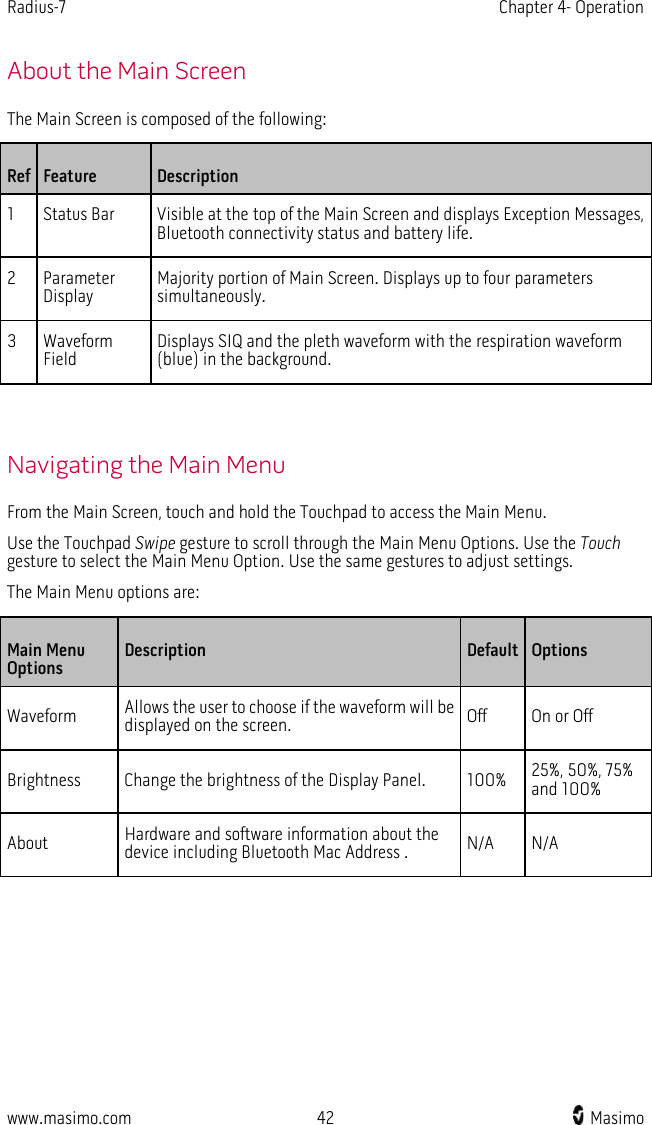


![www.masimo.com 69 Masimo Chapter 7- Specifications Measurement Range Measurement Display Range SpO2 (Oxygen Saturation) 0% to 100% SpMet (Methemoglobin) 0% to 99.9% SpCO (Carboxyhemoglobin) 0% to 99% SpHb (Hemoglobin) 0 g/dL to 25.0 g/dL SpOC (Oxygen Content) 0 ml of O2/dL to 35 ml of O2/dL of blood PR (Pulse Rate) 25 bpm to 240 bpm PI (Perfusion Index) 0.02% to 20% PVI (Pleth Variability Index) 0% to 100% RRa (Respiration Rate) 0 breaths per minute to 70 breaths per minute RRp (Respiration Rate) 0 breaths per minute to 70 breaths per minute Accuracy Oxygen Saturation (SpO2) [1] No Motion [1] (SpO2 from 60% to 80%) Adults, Pediatrics 3% No Motion [2] (SpO2 from 70% to 100%) Adults, Pediatrics 2%](https://usermanual.wiki/Masimo/RADIUS/User-Guide-2594625-Page-69.png)
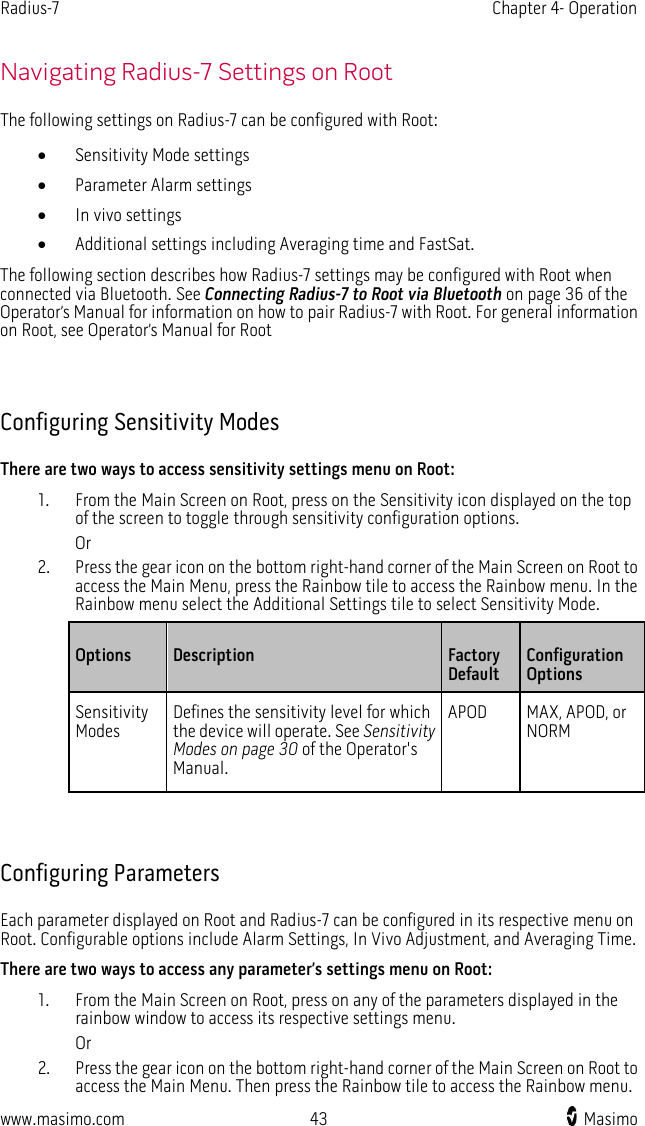
![Radius-7 Chapter 7- Specifications www.masimo.com 70 Masimo Motion [3] (SpO2 from 70% to 100%) Adults, Pediatrics 3% Low perfusion [4] (SpO2 from 70% to 100%) Adults, Pediatrics 2% Pulse Rate (PR) Range 25 to 240 bpm No motion Adults, Pediatrics 3 bpm Motion [5] Adults, Pediatrics 5 bpm Low Perfusion Adults, Pediatrics 3 bpm Carboxyhemoglobin Level (SpCO) [1] Range of 1% to 40% Adults, Pediatrics 3% Methemoglobin Level (SpMet) [1] Range 1% to 15% Adults, Pediatrics 1% Total Hemoglobin SpHb [6] Range of 8 g/dL to 17 g/dL Adults, Pediatrics 1 g/dL Respiratory Rate (RRa, RRp) [7] Range of 4 to 70 bpm Adults, Pediatrics 1 breath per minute Resolution Parameter Resolution %SpO2 1% %SpCO 1% %SpMet 0.1%](https://usermanual.wiki/Masimo/RADIUS/User-Guide-2594625-Page-70.png)
![Radius-7 Chapter 7- Specifications www.masimo.com 71 Masimo Parameter Resolution SpHb g/dL 0.1 g/dL Pulse Rate 1 beats per minute Respiration Rate 1 breaths per minute Electrical Battery Module of Radius-7 Type Lithium ion Capacity 12 hours Charging Time ≤ 6 hours For information on Root Battery see Specifications in the Operator's Manual for Root Environmental Radius-7 Environmental Conditions: Environmental Conditions Operating Temperature 41°F to 104°F (5°C to 40°C) Transport/Storage Temperature -4°F to 122°F (-20°C to 50°C) [8] Operating Humidity 10% to 95%, non-condensing Non-Operating Humidity 10% to 95%, non-condensing Operating Altitude 540 mbar to 1060 mbar at ambient temperature and humidity For Environmental Specifications for Root with Battery Charging Adapter see Operator's Manual for Root.](https://usermanual.wiki/Masimo/RADIUS/User-Guide-2594625-Page-71.png)
![Radius-7 Chapter 7- Specifications www.masimo.com 72 Masimo Physical Characteristics Item Description Dimensions 5.1” x 2.8 ” x 1.2” (130 mm x 70 mm x 30 mm) Weight 0.34lbs. (155g) Alarms Parameter Alarm Range SpO2 1% to 99% SpCO 1% to 98% SpMet 0.1% to 99.5% SpHb 1.0 g/dL to 24.5 g/dL RR 5 to 69 breaths per minute PI 0.03% to 19% PVI 1% to 99% Pulse Rate 30 bpm to 235 bpm SpOC 1 g/dL to 34 g/dL Alarm Characteristic Description Alarm Volume (Set at 100%) High Priority Medium Priority Medium Priority < High Priority Sensitivity NORM, MAX, APOD [8]](https://usermanual.wiki/Masimo/RADIUS/User-Guide-2594625-Page-72.png)
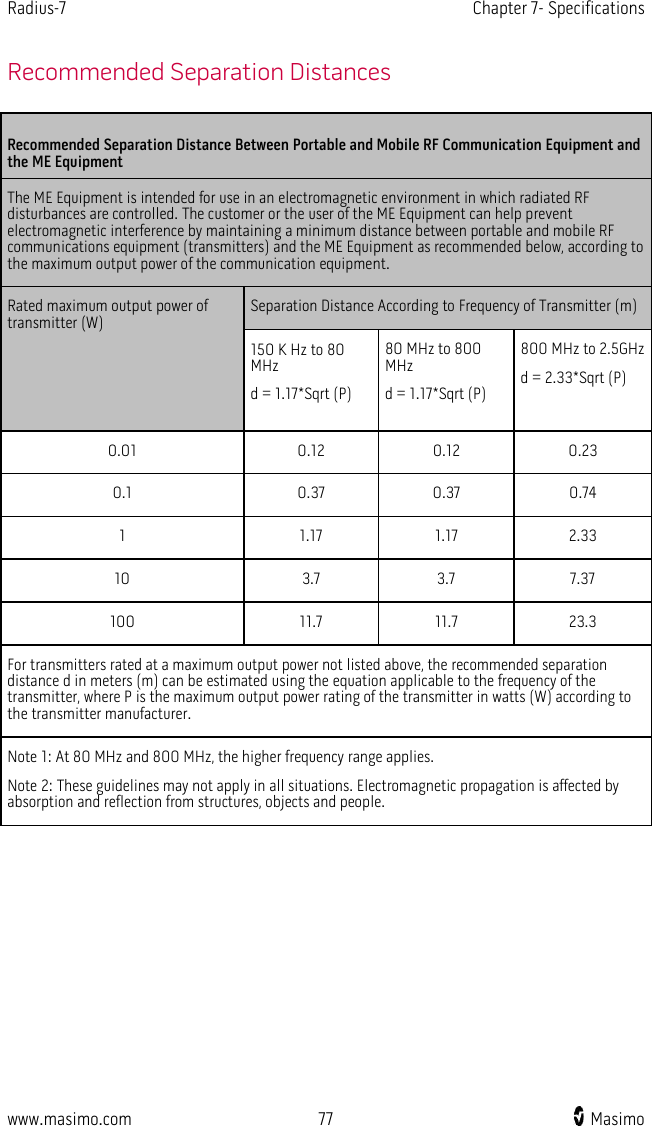
![Radius-7 Chapter 7- Specifications www.masimo.com 76 Masimo Guidance and Manufacturer's Declaration - Electromagnetic Immunity 80 MHz to 800 MHz 800 MHz to 2,5 GHz where P is the maximum output power rating of the transmitter in watts (W) according to the transmitter manufacturer and d is the recommended separation distance in meters (m). Field strengths from fixed RF transmitters, as determined by an electromagnetic site survey, should be less than the compliance level in each frequency rangeb. Interference may occur in the vicinity of equipment marked with the following symbol: Note 1: At 80 MHz and 800 MHz, the higher frequency range applies. Note 2: These guidelines may not apply in all situations. Electromagnetic propagation is affected by absorption and reflection from structures, objects and people. Field strengths from fixed transmitters, such as base stations for radio (cellular/cordless) telephones and land mobile radios, amateur radio, AM and FM radio broadcast and TV broadcast cannot be predicted theoretically with accuracy. To assess the electromagnetic environment due to fixed RF transmitters, an electromagnetic site survey should be considered. If the measured field strength in the location in which the ME Equipment is used exceeds the applicable RF compliance level above, the ME Equipment should be observed to verify normal operation. If abnormal performance is observed, additional measures may be necessary, such as re-orienting or relocating the ME Equipment. b Over the frequency range 150 kHz to 80 MHz, field strengths should be less than [V1] V/m.](https://usermanual.wiki/Masimo/RADIUS/User-Guide-2594625-Page-76.png)
![Radius-7 Chapter 7- Specifications www.masimo.com 80 Masimo Citations [1] SpO2, SpCO, and SpMet accuracy was determined by testing on healthy adult male and female volunteers in the range 60% to 100% SpO2, 0% to 40% SpCO, and 0% to 15% SpMet against a laboratory CO-Oximeter. SpO2 and SpMet accuracy was determined on 16 neonatal NICU patients ranging in age from 7 days to 135 days old and weighing between 0.5 kg and 4.25 kg. Seventy-nine data samples were collected over a range of 70% to 100% SaO2 and 0.5% to 2.5% HbMet with a resultant accuracy of 2.9% SpO2 and 0.9% SpMet. Contact Masimo for testing specifications. [2] The Masimo rainbow SET technology with Masimo sensors has been validated for no motion accuracy in human blood studies on healthy adult male and female volunteers with light to dark skin pigmentation in induced hypoxia studies in the range of 70%-100% SpO2 against a laboratory CO-Oximeter and ECG monitor. This variation equals ±1 standard deviation which encompasses 68% of the population weight. [3] The Masimo rainbow SET technology with Masimo sensors has been validated for motion accuracy in human blood studies on healthy adult male and female volunteers with light to dark skin pigmentation in induced hypoxia studies while performing rubbing and touching motions, at 2 to 4 Hz at an amplitude of 1 to 2 cm and a non-repetitive motion between 1 to 5 Hz at an amplitude of 2 to 3 cm in induced hypoxia studies in the range of 70%-100% SpO2 against a laboratory CO-Oximeter and ECG monitor. This variation equals ±1 standard deviation. Plus or minus one standard deviation encompasses 68% of the population. [4] The Radius-7 has been validated for low perfusion accuracy in bench-top testing against a Biotek Index 2TM* simulator and Masimo's simulator with signal strengths of greater than 0.02% and transmission of greater than 5% for saturations ranging from 70%-100%. This variation equals ±1 standard deviation. Plus or minus one standard deviation encompasses 68% of the population. [5] Masimo rainbow SET technology with Masimo sensors has been validated for pulse rate accuracy for the range of 25-240 bpm in bench top testing against a Biotek Index 2 simulator. This variation equals ±1 standard deviation which encompasses 68% of the population. [6] SpHb accuracy has been validated on healthy adult male and female volunteers and on surgical patients with light to dark skin pigmentation in the range of 8 g/dL to 17 g/dL SpHb against a laboratory CO-Oximeter. The variation equals ±1 standard deviation which encompasses 68% of the population. The SpHb accuracy has not been validated with motion or low perfusion. [7] Respiration rate accuracy for the Masimo Acoustic Respiration Sensor and device has been validated for the range of 4 to 70 breaths per minute in bench top testing. Clinical validation for up to 30 breaths per minute was also performed with the Masimo Acoustic Respiration Sensor and Instrument. [8] Maximum sensitivity mode fixes perfusion limit to 0.02%. *Registered trademark of Fluke Biomedical Corporation, Everett, Washington.](https://usermanual.wiki/Masimo/RADIUS/User-Guide-2594625-Page-80.png)