Masimo RADIUS Radius-7 User Manual Radius 7 Operator s Manual CE LAB 8303B
Masimo Corporation Radius-7 Radius 7 Operator s Manual CE LAB 8303B
Masimo >
User Manual
Radius-7™ Wearable Pulse
CO-Oximeter
Operator's Manual
www.masimo.com 3 Masimo
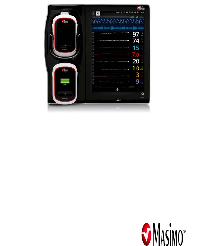
These operating instructions intend to provide the necessary information for proper operation of the Radius-7 Wearable
Pulse CO-Oximeter. The Operator's Manual describes how Radius-7 information is displayed when used with Root,
including display details as well as accessing and changing user-configurable settings. For additional information
related to Root, refer to the Operator's Manual for Root.
There may be information provided in this manual that is not relevant for your system.
General knowledge of pulse oximetry and an understanding of the features and functions of the Radius-7 Wearable Pulse
CO-Oximeter are prerequisites for proper use.
Do not operate the Radius-7 Wearable Pulse CO-Oximeter without completely reading and understanding these
instructions.
Cleared Use Only: The device and related accessories are CE Marked for non-invasive patient monitoring and may
not be used for any processes, procedures, experiments or any other use for which the device is not intended or
cleared by the applicable regulatory authorities, or in any manner inconsistent with the instructions for use or
labeling.
NOTICE
Purchase or possession of this device does not carry any express or implied license to use with replacement parts which
would, alone or in combination with this device, fall within the scope of one of the relating patents.
For professional use. See instructions for use for full prescribing information, including indications,
contraindications, warnings, precautions and adverse events.
For further information contact:
Masimo Corporation
40 Parker
Irvine, CA 92618
USA
Tel.: 949-297-7000
Fax.: 949-297-7001
www.masimo.com
EU authorized representative for Masimo Corporation:
MDSS GmbH
Schiffgraben 41
D-30175 Hannover, Germany
E357969
MEDICAL ELECTRICAL EQUIPMENT
WITH RESPECT TO ELECTRIC SHOCK,
FIRE AND MECHANICAL HAZARDS ONLY
IN ACCORDANCE WITH ANSI/AAMI ES 60601-1:2005,
CAN/CSA C22.2 No. 60601-1:2008, and applicable Particular
(IEC 60601-2-49:2011, EN/ISO 80601-2-61:2011 and related
Collateral (ANSI/AAMI/IEC 60601-1-8:2006) Standards for
which the product has been found to comply by UL.
Patents: www.masimo.com/patents.htm.
®, Adaptive Probe Off Detection®, APOD®, Discrete Saturation Transform®, DST®, FastSat®, FST®, Masimo®, Pulse
CO-Oximeter®, PVI®, rainbow®, rainbow Resposable®, RRa®, SET®, Signal Extraction Technology®, Signal IQ®,
SpCO®, SpHb®, SpMet® are federally registered trademarks of Masimo Corporation.
Radius-7™, rainbow Acoustic Monitoring™, RAM™ Adaptive Threshold Alarm™, In Vivo Adjustment™ and RRp™ are
trademarks of Masimo Corporation. All other trademarks and registered trademarks are property of their respective
owners.
© 2014 Masimo Corporation.

Radius-7 Contents
www.masimo.com 4 Masimo
Contents
About this Manual ------------------------------------------------------------------------------------------- 7
Product Description, Features and Indications for Use ---------------------------------------------- 9
Product Description ------------------------------------------------------------------------------------ 9
Indications for Use ------------------------------------------------------------------------------------- 9
Safety Information, Warnings and Cautions ---------------------------------------------------------- 11
Safety Warnings and Cautions----------------------------------------------------------------------- 11
Performance Warnings and Cautions--------------------------------------------------------------- 12
Cleaning and Service Warnings and Cautions ---------------------------------------------------- 16
Compliance Warnings and Cautions---------------------------------------------------------------- 16
Chapter 1- Technology Overview ------------------------------------------------------------------------ 19
Signal Extraction Technology® (SET®) ------------------------------------------------------------ 19
rainbow Pulse CO-Oximetry Technology ----------------------------------------------------------- 22
rainbow Acoustic Monitoring™ (RAM™) ------------------------------------------------------------ 25
In Vivo Adjustment™ ---------------------------------------------------------------------------------- 27
Signal IQ® (SIQ) --------------------------------------------------------------------------------------- 28
Adaptive Threshold Alarm (ATA)-------------------------------------------------------------------- 29
FastSat® (FST®) --------------------------------------------------------------------------------------- 29
Sensitivity Modes ------------------------------------------------------------------------------------- 30
Chapter 2- System Components ------------------------------------------------------------------------ 31
General System Description ------------------------------------------------------------------------- 31
Radius-7 Instrument Module------------------------------------------------------------------------- 31
Radius-7 Battery Module ------------------------------------------------------------------------------ 33
Radius-7 Armband ------------------------------------------------------------------------------------- 34
Battery Charging Adapter ---------------------------------------------------------------------------- 34
Chapter 3- Setup------------------------------------------------------------------------------------------- 35
Unpacking and Inspection --------------------------------------------------------------------------- 35
Preparation for Use ------------------------------------------------------------------------------------ 35
Charging the Radius-7 Battery Module ------------------------------------------------------------- 36
Connecting Radius-7 to Root via Bluetooth ------------------------------------------------------- 36
Securing Radius-7 to Patient ------------------------------------------------------------------------ 37
Removing Radius-7 from Patient -------------------------------------------------------------------- 39

Radius-7 Contents
www.masimo.com 5 Masimo
Chapter 4- Operation -------------------------------------------------------------------------------------- 41
Using the Touchpad ----------------------------------------------------------------------------------- 41
About the Main Screen -------------------------------------------------------------------------------- 42
Navigating the Main Menu --------------------------------------------------------------------------- 42
Navigating Radius-7 Settings on Root ------------------------------------------------------------- 43
Chapter 5- Alarms and Messages ---------------------------------------------------------------------- 59
About Alarms ------------------------------------------------------------------------------------------ 59
Alarm Priorities ---------------------------------------------------------------------------------------- 59
Alarm Management----------------------------------------------------------------------------------- 60
Messages ------------------------------------------------------------------------------------------------ 61
Chapter 6- Troubleshooting ----------------------------------------------------------------------------- 65
Troubleshooting Measurements -------------------------------------------------------------------- 65
Troubleshooting Radius-7 --------------------------------------------------------------------------- 66
Chapter 7- Specifications -------------------------------------------------------------------------------- 69
Measurement Range ---------------------------------------------------------------------------------- 69
Accuracy ------------------------------------------------------------------------------------------------ 69
Resolution ----------------------------------------------------------------------------------------------- 70
Electrical ------------------------------------------------------------------------------------------------- 71
Environmental ------------------------------------------------------------------------------------------ 71
Physical Characteristics ------------------------------------------------------------------------------- 72
Alarms ---------------------------------------------------------------------------------------------------- 72
Display Indicators -------------------------------------------------------------------------------------- 73
EMC Compliance --------------------------------------------------------------------------------------- 73
Safety Standards Compliance ------------------------------------------------------------------------ 73
Radio Compliance -------------------------------------------------------------------------------------- 74
Guidance and Manufacturer's Declaration- Electromagnetic Emissions --------------------- 75
Guidance and Manufacturer's Declaration- Electromagnetic Immunity --------------------- 75
Recommended Separation Distances -------------------------------------------------------------- 77
Symbols -------------------------------------------------------------------------------------------------- 78
Citations ------------------------------------------------------------------------------------------------ 80
Chapter 8 - Service and Maintenance ------------------------------------------------------------------ 81
Cleaning ------------------------------------------------------------------------------------------------- 81
Battery Operation and Maintenance ---------------------------------------------------------------82

Radius-7 Contents
www.masimo.com 6 Masimo
Safety Checks ------------------------------------------------------------------------------------------- 82
Repair Policy -------------------------------------------------------------------------------------------- 83
Return Procedure -------------------------------------------------------------------------------------- 84
Contacting Masimo ------------------------------------------------------------------------------------ 84
Appendix ---------------------------------------------------------------------------------------------------- 87
Concepts of Alarm Response Delay ----------------------------------------------------------------- 87
Index --------------------------------------------------------------------------------------------------------- 89

www.masimo.com 7 Masimo
About this Manual
This manual explains how to set up and use the Radius-7 Wearable Pulse CO-Oximeter.
Important safety information relating to general use of the Radius-7 appears in this manual.
Read and follow any warnings, cautions, and notes presented throughout this manual. The
following are explanations of warnings, cautions, and notes.
A warning is given when actions may result in a serious outcome (for example, injury, serious
adverse effect, death) to the patient or user.
WARNING: This is an example of a warning statement.
A caution is given when any special care is to be exercised by the patient or user to avoid
injury to the patient, damage to this device or damage to other property.
CAUTION: This is an example of a caution statement.
A note is given when additional general information is applicable.
Note: This is an example of a note.

www.masimo.com 9 Masimo
Product Description, Features and
Indications for Use
Product Description
The Radius-7 is a non-invasive device that measures arterial oxygen saturation (SpO2), pulse
rate (PR), perfusion index (PI), and Pleth Variability Index (PVI®) along with optional
measurements of hemoglobin (SpHb®), carboxyhemoglobin (SpCO®), total oxygen content
(SpOC), methemoglobin (SpMet®), Acoustic Respiration Rate (RRa®) and Pleth Respiration
Rate (RRp™).
The following key features are available for the Radius-7:
• Patient wearable device for continuous monitoring when the patient is
ambulatory.
• Bluetooth radio for transfer of parameter data to the Root patient monitoring and
connectivity platform.
• Masimo SET® and rainbow®SET technology performance.
• SpO2 and pulse rate monitoring in motion and low perfusion environments.
• Continuous and non-invasive monitoring of carboxyhemoglobin (SpCO),
methemoglobin (SpMet), and total hemoglobin (SpHb).
• Respiration rate determined by the acoustic (RRa) or plethysmographic waveform
(RRp).
Indications for Use
The Radius-7 and accessories are indicated for the continuous non-invasive monitoring of
functional oxygen saturation of arterial hemoglobin (SpO2), pulse rate (PR),
carboxyhemoglobin saturation (SpCO), methemoglobin saturation (SpMet), total hemoglobin
concentration (SpHb), and/or respiratory rate (RRa). The Radius-7 and accessories are
indicated for use with adult and pediatric patients during both no motion and motion
conditions, and for patients who are well or poorly perfused in hospitals and hospital-type
facilities.

www.masimo.com 11 Masimo
Safety Information, Warnings and
Cautions
CAUTION: Radius-7 Wearable Pulse CO-Oximeter is to be operated by, or under the
supervision of, qualified personnel only. The manual, accessories, directions for use, all
precautionary information, and specifications should be read before use.
Safety Warnings and Cautions
WARNING: Do not use Radius-7 if it appears or is suspected to be damaged.
WARNING: Always use Radius-7 in conjunction with Root. Do not use parts from other
systems. Injury to personnel or equipment damage could occur.
WARNING: Do not adjust, repair, open, disassemble, or modify the Radius-7. Injury to
personnel or equipment damage could occur.
WARNING: Do not start or operate the Radius-7 unless the setup was verified to be correct.
WARNING: To ensure safety, only use Masimo authorized devices with Radius-7.
WARNING: All sensors and cables are designed for use with specific devices. Verify the
compatibility of the device, cable, and sensor before use; otherwise degraded performance
and/or patient injury can result.
WARNING: Explosion Hazard: Do not use the Radius-7 in the presence of flammable
anesthetics or other flammable substance in combination with air, oxygen-enriched
environments, or nitrous oxide.
WARNING: Do not use the Radius-7 during magnetic resonance imaging (MRI) or in an MRI
environment.
WARNING: Radius-7 may be used during defibrillation. However, to reduce the risk of electric
shock, the operator should not touch the Radius-7 during defibrillation.
WARNING: Electrical Shock Hazard: To protect against injury, follow the directions below:
• Avoid placing the device on surfaces with visible liquid spills.
• Do not soak or immerse the device in liquids.
• Do not attempt to sterilize the device.
• Use cleaning solutions only as instructed in this Operator's Manual.
• Do not attempt to clean the Radius-7 while monitoring patient.

Radius-7 Safety Information, Warnings and Cautions
www.masimo.com 12 Masimo
WARNING: To ensure safety, avoid placing anything on the device during operation.
WARNING: As with all medical equipment, carefully route patient cabling to reduce the
possibility of patient entanglement or strangulation.
WARNING: The Armband site must be checked frequently or per clinical protocol to ensure
adequate securement, circulation and skin integrity.
WARNING: Armbands applied too tightly or that become tight due to edema will cause
inaccurate readings and can cause pressure injury.
WARNING: Discontinue and dispose of Armband if it appears to be stained or becomes
excessively moist to minimize risk of skin irritation.
CAUTION: Electrical Shock Hazard: Do not place the Battery Charger of Radius-7 on or near
the patient. Injury to patient could occur.
Note: Use and store the Radius-7 in accordance with specifications. See the Specifications
section in this manual.
Performance Warnings and Cautions
WARNING: Radius-7 is not an apnea monitor.
WARNING: Radius-7 should not be used as a replacement or substitute for ECG-based
arrhythmia analysis.
WARNING: Radius-7 may be used during defibrillation, but this may affect the accuracy or
availability of the parameters and measurements.
WARNING: Do not use during electrocautery. This may affect the accuracy or availability of
the parameters and measurements.
WARNING: Radius-7 is intended only as an adjunct device in patient assessment. It should
not be used as the sole basis for diagnosis or therapy decisions. It must be used in
conjunction with clinical signs and symptoms.
WARNING: If any measurement seems questionable, first check the patient’s vital signs by
alternate means and then check Radius-7 for proper functioning.
WARNING: When the Radius-7 is connected to Root, all audible alarms will be provided on
the Root.
WARNING: Always pair Radius-7 with Root.
WARNING: Avoid placing Radius-7 against a surface that may cause the alarm to be muffled.
WARNING: Misapplied sensor or sensors that become partially dislodged may cause either
over or under reading of actual arterial oxygen saturation.
WARNING: With very low perfusion at the monitored site, the reading may read lower than
core arterial oxygen saturation.
WARNING: Venous congestion may cause under reading of actual arterial oxygen saturation.
Therefore, assure proper venous outflow from monitored site.
WARNING: Excessive venous pulsations may cause erroneous low SpO2 readings (e.g.
tricuspid valve regurgitation,Trendelenburg position).
WARNING: Interfering Substances: Dyes or any substance containing dyes, that change usual
blood pigmentation may cause erroneous readings.

Radius-7 Safety Information, Warnings and Cautions
www.masimo.com 13 Masimo
WARNING: SpO2 is empirically calibrated in healthy adult volunteers with normal levels of
carboxyhemoglobin (COHb) and methemoglobin (MetHb).
WARNING: If SpO2 values indicate hypoxemia, a laboratory blood sample should be taken to
confirm the patient’s condition.
WARNING: Inaccurate SpO2 readings may be caused by:
• Improper sensor application.
• Elevated levels of COHb and MetHb: High levels of COHb or MetHb may
occur with a seemingly normal SpO2. When elevated levels of COHb or
MetHb are suspected, laboratory analysis (CO-Oximetry) of a blood
sample should be performed.
• Intravascular dyes such as indocyanine green or methylene blue.
• Externally applied coloring and texture such as nail polish, acrylic nails,
glitter, etc.
• Elevated levels of bilirubin.
• Severe anemia.
• Low arterial perfusion.
• Motion artifact.
WARNING: Inaccurate SpHb and SpOC readings may be caused by:
• Improper sensor application.
• Intravascular dyes, such as indocyanine green or methylene blue.
• Externally applied coloring and texture, such as nail polish, acrylic nails,
glitter, etc.
• Elevated PaO2 levels.
• Elevated levels of bilirubin.
• Low arterial perfusion.
• Motion artifact.
• Low arterial oxygen saturation levels.
• Elevated carboxyhemoglobin levels.
• Elevated methemoglobin levels.
• Hemoglobinopathies and synthesis disorders such as thalassemias, Hb
s, Hb c, sickle cell, etc.
• Vasospastic disease such as Raynaud's.
• Elevate altitude
• Peripheral vascular disease.
• Liver disease.
• EMI radiation interference.
WARNING: Inaccurate SpCO and SpMet readings may be caused by:
• Improper sensor application.
• Intravascular dyes such as indocyanine green or methylene blue.
• Abnormal hemoglobin levels.
• Low arterial perfusion.
• Low arterial oxygen saturation levels.
• Elevated total bilirubin levels.

Radius-7 Safety Information, Warnings and Cautions
www.masimo.com 14 Masimo
• Motion artifact.
• SpCO readings may not be provided if SpO2 readings are less than 90%
• SpCO readings may not be provided if SpMet readings are greater than
2%
WARNING: SpCO readings may not be provided if there are low arterial oxygen saturation
levels or elevated methemoglobin levels.
WARNING: Inaccurate respiration rate measurements may be caused by:
• Improper sensor application.
• Low arterial perfusion.
• Motion artifact.
• Low arterial oxygen saturation.
• Excessive ambient or environmental noise.

Radius-7 Safety Information, Warnings and Cautions
www.masimo.com 15 Masimo
CAUTION: Do not place the Radius-7 on electrical equipment that may affect the device,
preventing it from working properly.
CAUTION: Failure to charge Radius-7 promptly after a Low Battery alarm may result in the
device shutting down.
CAUTION: If using Radius-7 during full body irradiation, keep the sensor out of the radiation
field. If the sensor is exposed to the radiation, the reading might be inaccurate or the device
might read zero for the duration of the active irradiation period.
CAUTION: When patients are undergoing photodynamic therapy they may be sensitive to
light sources. Pulse oximetry may be used only under careful clinical supervision for short
time periods to minimize interference with photodynamic therapy.
CAUTION: High ambient light sources such as surgical lights (especially those with a xenon
light source), bilirubin lamps, fluorescent lights, infrared heating lamps, and direct sunlight
can interfere with the performance of the sensor.
CAUTION: To prevent interference from ambient light, ensure that the sensor is properly
applied, and cover the sensor site with opaque material, if required. Failure to take this
precaution in high ambient light conditions may result in inaccurate measurements.
CAUTION: If the Low Perfusion message is frequently displayed, find a better perfused
monitoring site. In the interim, assess the patient and, if indicated, verify oxygenation status
through other means.
CAUTION: To minimize radio interference, other electrical equipment that emits radio
frequency transmissions should not be in close proximity to Radius-7.
CAUTION: In order to maintain Bluetooth connectivity with Root, ensure that the Radius-7 is
within approximately 7 m radius and line of sight of Root.
CAUTION: When using multiple Radius-7 and Root systems, re-dock the Battery Module to
Root to ensure proper pairing before connecting the Radius-7 to the patient.
CAUTION: To ensure that alarm limits are appropriate for the patient being monitored, check
the limits each time Radius-7 is used.
CAUTION: If the Radius-7 and Root become unable to communicate, parameters and
measurements will not show on the Root; however, this will not affect Radius-7's ability to
monitor the patient.
Note: Before securing Radius-7 onto the patient, make sure the Battery Module is sufficiently
charged.
Note: Always charge Radius-7 when it is not in use to ensure that the Radius-7 Battery
Module remains fully charged.
Note: All batteries lose capacity with age, thus the amount of run time at Low Battery will
vary depending upon the age of the Battery Module.
Note: The Radius-7 display enters standby mode after 30s of inactivity. The Radius-7 display
entering standby mode does not affect the monitoring of the patient.
Note: A functional tester cannot be used to assess the accuracy of Radius-7.
Note: When monitoring acoustic respiration, Masimo recommends minimally monitoring
both oxygenation (SpO2) and respiration (RRa).
Note: When using Radius-7 in the Maximum Sensitivity setting, performance of the "Sensor
Off" detection may be compromised. If the sensor becomes dislodged from the patient in this

Radius-7 Safety Information, Warnings and Cautions
www.masimo.com 16 Masimo
setting, false readings may occur due to environmental "noise" such as light, vibration, and
excessive air movement.
Cleaning and Service Warnings and Cautions
WARNING: Do not attempt to reprocess, recondition or recycle the Radius-7 as these
processes may damage the electrical components, potentially leading to patient harm.
WARNING: Electric Shock Hazard: The battery in the Battery Module should not be removed
from the Radius-7.
WARNING: Do not incinerate the Radius-7 Battery Module.
CAUTION: Only perform maintenance procedures specifically described in the manual.
Otherwise, return the Radius-7 for servicing.
CAUTION: Electrical Shock: Before cleaning Radius-7, always turn it off and physically
disconnect it from Root.
CAUTION: Do not use petroleum-based or acetone solutions, or other harsh solvents, to clean
the Radius-7. These substances affect the device’s materials and device failure can result.
CAUTION: Do not submerge the Radius-7 in any cleaning solution or attempt to sterilize by
autoclave, irradiation, steam, gas, ethylene oxide or any other method. This will seriously
damage the device.
CAUTION: To prevent damage, do not soak or immerse Radius-7 in any liquid solution.
Compliance Warnings and Cautions
WARNING: Changes or modifications not expressly approved by Masimo shall void the
warranty for this equipment.
WARNING: In accordance with international telecommunication requirements, the frequency
band of 2.4 GHz and 5.15 to 5.25 GHz is only for indoor usage to reduce potential for harmful
interference to co-channel mobile satellite systems.
CAUTION: Disposal of Product: Comply with local laws in the disposal of the device and/or its
accessories.
CAUTION: Dispose of used batteries according to required country or regional instructions.
Note: Use Radius-7 in accordance with the Environmental Specifications section in the
Operator's Manual.
Note: This device complies with Part 15 of the FCC Rules. Operation is subject to the
following two conditions: (1) This device may not cause harmful interference, and (2) this
device must accept any interference received, including interference that may cause
undesired operation.
Note: This equipment has been tested and found to comply with the limits for a Class B
digital device, pursuant to part 15 of the FCC Rules. These limits are designed to provide
reasonable protection against harmful interference in a residential installation. This
equipment generates, uses and can radiate radio frequency energy and, if not installed and
used in accordance with the instructions, may cause harmful interference to radio
communications. However, there is no guarantee that interference will not occur in a
particular installation. If this equipment does cause harmful interference to radio or

Radius-7 Safety Information, Warnings and Cautions
www.masimo.com 17 Masimo
television reception, which can be determined by turning the equipment off and on, the user
is encouraged to try to correct the interference by one or more of the following measures:
• Reorient or relocate the receiving antenna.
• Increase the separation between the equipment and receiver.
• Connect the equipment into an outlet on a circuit different from that to
which the receiver is connected.
• Consult the dealer or an experienced radio/TV technician for help.
Note: This equipment has been tested and found to comply with the Class B limits for
medical devices according to the EN 60601-1-2: 2007, Medical Device Directive 93/42/EEC.
These limits are designed to provide reasonable protection against harmful interference in all
establishments, including domestic establishments.
Note: This Class B digital apparatus complies with Canadian ICES-003.
www.masimo.com 19 Masimo
Chapter 1- Technology Overview
The following chapter contains general descriptions about parameters, measurements, and
the technology used by Masimo products.
Signal Extraction Technology® (SET®)
Masimo Signal Extraction Technology's signal processing differs from that of conventional
pulse oximeters. Conventional pulse oximeters assume that arterial blood is the only blood
moving (pulsating) in the measurement site. During patient motion, however, the venous
blood also moves, causing conventional pulse oximeters to read low values, because they
cannot distinguish between the arterial and venous blood movement (sometimes referred to
as noise).
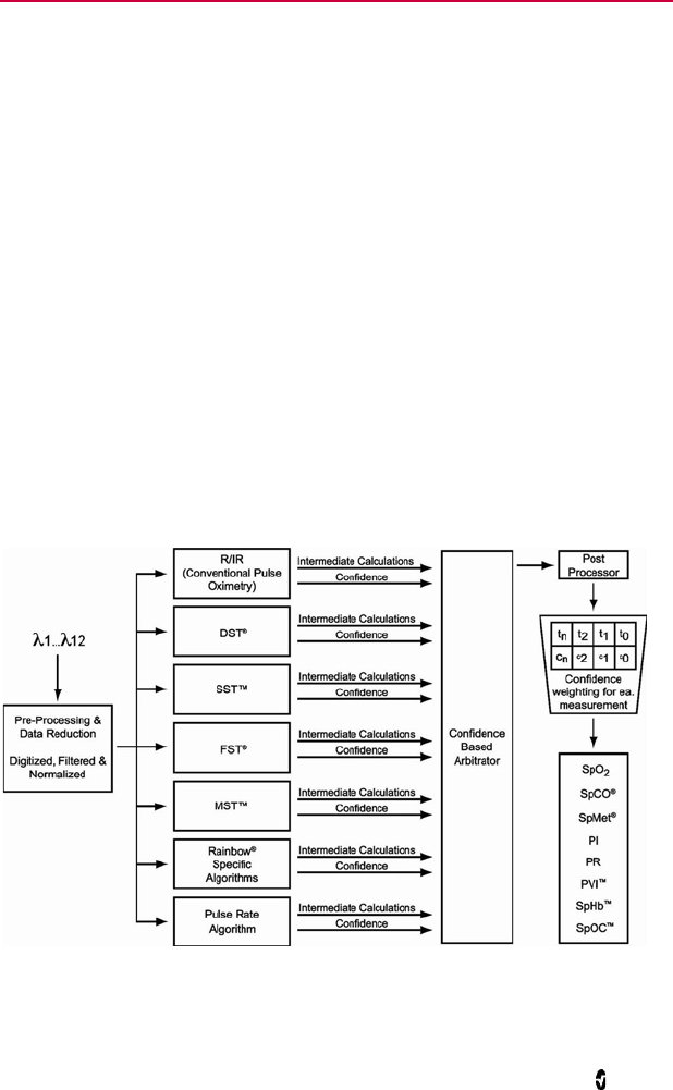
Masimo SET pulse oximetry utilizes parallel engines and adaptive filtering. Adaptive filters
are powerful because they are able to adapt to the varying physiologic signals and/or noise
and separate them by looking at the whole signal and breaking it down to its fundamental
components. The Masimo SET signal processing algorithm, Discrete Saturation Transform®
(DST®), in parallel with Fast Saturation Transform (FST®), reliably identifies the noise,
isolates it and, using adaptive filters, cancels it. It then reports the true arterial oxygen
saturation for display on the monitor.
Masimo rainbow SET Parallel Engines
This figure is for conceptual purposes only.
Radius-7 Chapter 1- Technology Overview
www.masimo.com 20 Masimo
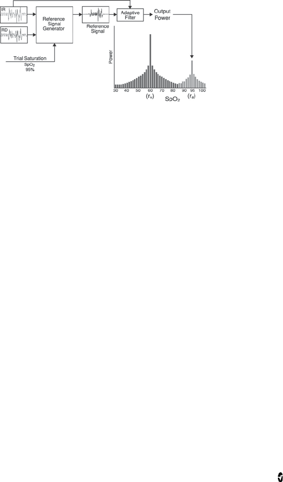
Masimo SET DST
This figure is for conceptual purposes only.
General Description for Oxygen Saturation (SpO2)
Pulse oximetry is governed by the following principles:
• Oxyhemoglobin (oxygenated blood) and deoxyhemoglobin (non-oxygenated
blood) differ in their absorption of red and infrared light (spectrophotometry).
• The amount of arterial blood in tissue changes with your pulse
(photoplethysmography). Therefore, the amount of light absorbed by the varying
quantities of arterial blood changes as well.
Successful Monitoring for SpO2, PR and PI
Stability of the SpO2 readings may be a good indicator of signal validity. Although stability is
a relative term, experience will provide a good feeling for changes that are artifactual or
physiological and the speed, timing, and behavior of each.
The stability of the readings over time is affected by the averaging time being used. The
longer the averaging time, the more stable the readings tend to become. This is due to a
dampened response as the signal is averaged over a longer period of time than during shorter
averaging times. However, longer averaging times delay the response of the oximeter and
reduce the measured variations of SpO2 and pulse rate.
Functional Oxygen Saturation (SpO2)
The Radius-7 is calibrated to measure and display functional oxygen saturation (SpO2): the
amount of oxyhemoglobin expressed as a percentage of the hemoglobin that is available to
transport oxygen.
Note that dyshemoglobins are not capable of transporting oxygen, but are recognized as
oxygenated hemoglobins by conventional pulse oximetry.

Radius-7 Chapter 1- Technology Overview
www.masimo.com 21 Masimo
General Description for Perfusion Index (PI)
The Perfusion Index (PI) is the ratio of the pulsatile blood flow to the non-pulsatile or static
blood in peripheral tissue. PI thus represents a non-invasive measure of peripheral perfusion
that can be continuously and non-invasively obtained from a pulse oximeter.
General Description for Pulse Rate (PR)
Pulse rate (PR), measured in beats per minute (BPM) is based on the optical detection of
peripheral flow pulse.
General Description for Pleth Variability Index (PVI)
The pleth variability index (PVI) is a measure of the dynamic changes in the perfusion index
(PI) that occur during the respiratory cycle. The calculation is accomplished by measuring
changes in PI over a time interval where one or more complete respiratory cycles have
occurred. PVI is displayed as a percentage (0-100%).
The utility of PVI is unknown at this time and requires further clinical studies. Technical
factors that may affect PVI include probe malposition and patient motion.
Radius-7 Chapter 1- Technology Overview
www.masimo.com 22 Masimo
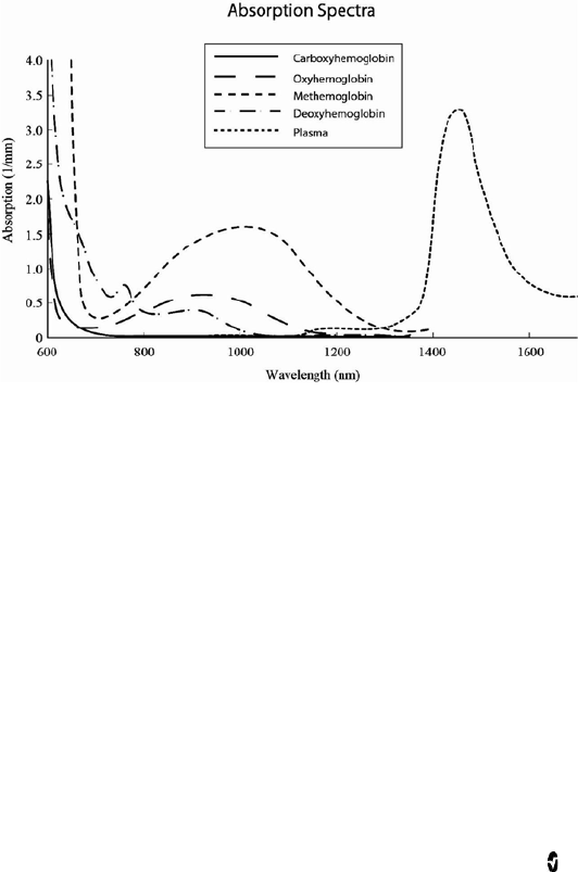
rainbow Pulse CO-Oximetry Technology
rainbow Pulse CO-Oximetry technology is governed by the following principles:
1. Oxyhemoglobin (oxygenated blood), deoxyhemoglobin (non-oxygenated blood),
carboxyhemoglobin (blood with carbon monoxide content), methemoglobin
(blood with oxidized hemoglobin) and blood plasma constituents differ in their
absorption of visible and infrared light (using spectrophotometry).
2. The amount of arterial blood in tissue changes with pulse
(photoplethysmography). Therefore, the amount of light absorbed by the varying
quantities of arterial blood changes as well.
Radius-7 Chapter 1- Technology Overview
www.masimo.com 23 Masimo
The Radius-7 uses a multi-wavelength sensor to distinguish between oxygenated blood,
deoxygenated blood, blood with carbon monoxide, oxidized blood and blood plasma.
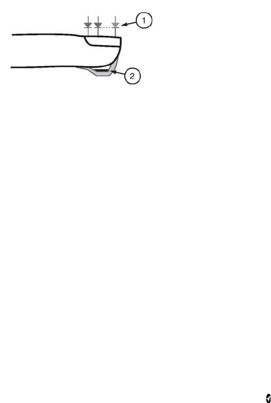
The Radius-7 utilizes a sensor with various light-emitting diodes (LEDs) that pass light
through the site to a diode (detector). Signal data is obtained by passing various visible and
infrared lights (LEDs, 500 to 1400nm) through a capillary bed (for example, a fingertip, a
hand, a foot) and measuring changes in light absorption during the blood pulsatile cycle. This
information may be useful to clinicians. The maximum radiant power of the strongest light is
rated at ≤ 25 mW. The detector receives the light, converts it into an electronic signal and
sends it to the Radius-7 for calculation.
1. Light Emitting Diodes (LEDs)
(7 + wavelengths)
2. Detector
Once the Radius-7 receives the signal from the sensor, it utilizes proprietary algorithms to
calculate the patient’s functional oxygen saturation (SpO2 [%]), blood levels of
carboxyhemoglobin (SpCO [%]), methemoglobin (SpMet [%]), total hemoglobin concentration
(SpHb [g/dL]) and pulse rate (PR). The SpCO, SpMet and SpHb measurements rely on a
multi-wavelength calibration equation to quantify the percentage of carbon monoxide and
methemoglobin and the concentration of total hemoglobin in arterial blood. The maximum
skin surface temperature is measured to be less than 41 º C (106º F) in a minimum 35 º C (95
º F) ambient. This is verified by Masimo sensor skin temperature test procedures.
General Description for Total Hemoglobin (SpHb)
Pulse CO-Oximetry is a continuous and non-invasive method of measuring the levels of total
hemoglobin (SpHb) in arterial blood. It relies on the same principles of pulse oximetry to
make its SpHb measurement.

Radius-7 Chapter 1- Technology Overview
www.masimo.com 24 Masimo
General Description for SpOC
Oxygen (O2) is carried in the blood in two forms, either dissolved in plasma or combined with
hemoglobin. The oxygen content calculated by the Pulse CO-Oximeter is referred to as SpOC
and is measured in units of ml O2/dL blood.
The above approximations result in the following reduced equation for oxygen content via the
Pulse CO-Oximeter:
SpOC (ml/dL*) = 1.31 (ml O2/g) x SpHb (g/dL) x SpO2 + 0.3 (ml O2/dL)
*When ml O2/g Hb is multiplied by g/dL of SpHb, the gram unit in the denominator of ml/g
cancels the gram unit in the numerator of g/dL resulting in ml/dL (ml of oxygen in one dL of
blood) as the unit of measure for SpOC.
General Description for Carboxyhemoglobin (SpCO)
Pulse CO-Oximetry is a continuous and non-invasive method of measuring the levels of
carboxyhemoglobin concentration (SpCO) in arterial blood. The device displays the data as a
percentage value for the SpCO, which reflect blood levels of carbon monoxide bound to
hemoglobin.
General Description for Methemoglobin (SpMet)
Pulse CO-Oximetry is a continuous and non-invasive method of measuring the levels of
methemoglobin concentration (SpMet) in arterial blood. The device displays the data as a
percentage value for the SpMet.
SpCO, SpMet, and SpHb Measurements During Patient Motion
The Radius-7 displays measurements of SpCO, SpMet, and SpHb during patient motion.
However, because of the changes in the physiological parameters such as blood volume,
arterial-venous coupling, etc. that occur during patient motion, the accuracy of such
measurements may not be reliable during excessive motion. In this case, the measurement
value for SpCO, SpMet, or SpHb displays as dashes (---) and a message (Low SpCO SIQ, Low
SpMet SIQ, or Low SpHb SIQ) displays to alert the clinician that the device does not have
confidence in the value due to poor signal quality caused by excessive motion or other signal
interference.
Radius-7 Chapter 1- Technology Overview
www.masimo.com 25 Masimo
rainbow Acoustic Monitoring™ (RAM™)
rainbow Acoustic Monitoring (RAM) continuously measures a patient’s respiration rate based
on airflow sounds generated in the upper airway. The Acoustic Sensor, which is applied on the
patient's neck, translates airflow sounds generated in the upper airway to an electrical signal
that can be processed to produce a respiration rate, measured as breaths per minute.
Respiratory sounds include sounds related to respiration such as breath sounds (during
inspiration and expiration), adventitious sounds, cough sounds, snoring sounds, sneezing
sounds, and sounds from the respiratory muscles [1].
These respiratory sounds often have different characteristics depending on the location of
recording [2] and they originate in the large airways where air velocity and air turbulence
induce vibration in the airway wall. These vibrations are transmitted, for example, through
the lung tissue, thoracic wall and trachea to the surface where they may be heard with the aid
of a stethoscope, a microphone or more sophisticated devices.
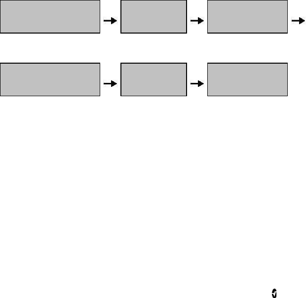
rainbow Acoustic Monitoring Architecture
The following figure illustrates how a respiratory sound produced by a patient can be turned
into a numerical measurement that corresponds to a respiratory parameter.
Patient Sensor Acquisition
System
Respiratory airflow to sound Sound to
electrical signal Electrical signal to
digital signal
Signal
Processing Envelope
Detection RRa Estimation
Digital signal to respiratory
measurement
Patient
The generation of respiratory sounds is primarily related to turbulent respiratory airflow in
upper airways. Sound pressure waves within the airway gas and airway wall motion contribute
to the vibrations that reach the body surface and are recorded as respiratory sounds.
Although the spectral shape of respiratory sounds varies widely from person to person, it is
often reproducible within the same person, likely reflecting the strong influence of individual
airway anatomy [2-6].

Radius-7 Chapter 1- Technology Overview
www.masimo.com 26 Masimo
Acoustic Sensor
The sensor captures respiratory sounds (and other biological sounds) much like a microphone
does. When subjected to a mechanical strain, (e.g., surface vibrations generated during
breathing), the sensor becomes electrically polarized.
The degree of polarization is proportional to the applied strain. The output of the sensor is an
electric signal that includes a sound signal that is modulated by inspiratory and expiratory
phases of the respiratory cycle.
Acquisition System
The acquisition system converts the electric signal provided by the sensor into a digital
signal. This format allows the signal to be processed by a computing device.
Signal Processing
The digital signal produced by the acquisition system is converted into a measurement that
corresponds to the respiratory parameter of interest. As shown in the previous figure, this can
be performed by, for example, determining the digital signal envelope or outline which in turn
may be utilized to determine the respiratory rate. In this way, a real-time, continuous breath
rate parameter can be obtained and displayed on a monitor which, in many cases, may be
real-time and continuous.
The respiratory cycle envelope signal processing principle is similar to methods that sample
airway gasses and subsequently determine a respiratory rate.
Citations
[1] A.R.A. Sovijärvi, F. Dalmasso, J. Vanderschool, L.P. Malmberg, G. Righini, S.A.T. Stoneman.
Definition of terms for applications of respiratory sounds. Eur Respir Rev 2000; 10:77,
597-610.
[2] Z. Moussavi. Fundamentals of respiratory sounds analysis. Synthesis lectures on
biomedical engineering #8. Morgan & Claypool Publishers, 2006.
[3] Olsen, et al. Mechanisms of lung sound generation. Semin Respir Med 1985; 6: 171-179.
[4] Pastercamp H, Kraman SS, Wodicka GR. Respiratory sounds – Advances beyond the
stethoscope. Am J Respir Crit Care Med 1977; 156: 974-987.
[5] Gavriely N, Cugell DW. Airflow effects on amplitude and spectral content of normal breath
sounds. J Appl Physiol 1996; 80: 5-13.
[6] Gavrieli N, Palti Y, Alroy G. Spectral characteristics of normal breath sounds. J Appl
Physiol 1981; 50: 307-314.

Radius-7 Chapter 1- Technology Overview
www.masimo.com 27 Masimo
In Vivo Adjustment™
The In Vivo Adjustment feature lets clinicians manually adjust one or more clinical
parameters to match that of a corresponding laboratory reference for continuous trending. To
remind clinicians that the feature is active, an offset value displays alongside the adjusted
parameter value.
In Vivo Adjustment for a parameter can be turned on by accessing the In Vivo screen in the
settings menu of that parameter. After enabling the feature, set an offset value. Once the
feature is enabled, a positive or a negative offset value appears on the main display
underneath the parameter value.
The In Vivo offset is set to zero for any of the following:
• Cable or sensor is disconnected from instrument.
• Sensor goes off patient causing a sensor initialization to occur.
• Eight hours has elapsed since the In Vivo value was activated.
• Restoration of factory defaults.
• The user turns off In Vivo.
Offset Value
When In Vivo Adjustment is activated for a specific parameter, the offset value appears
beneath that specific parameter on the secondary display connected to the device. A positive
value means that the displayed parameter value has been increased (according to a
laboratory reference value as entered by a clinician) and a negative value means the
displayed parameter value has been decreased (according to a laboratory reference value as
entered by a clinician).
In Vivo Adjustment can be set to On or Off. The factory default setting is Off. If set to On, the
parameter value is adjusted and an offset value appears. The offset value is set by the user.
Note: When In Vivo Adjustment is enabled for a specific parameter, the alarm states for that
parameter are based on the offset values as opposed to the measured values. Check the alarm
limits each time In Vivo Adjustment is enabled.

Radius-7 Chapter 1- Technology Overview
www.masimo.com 28 Masimo
Signal IQ® (SIQ)
The display provides a visual indicator of the plethysmogram signal quality and an alert when
the displayed SpO2 values are not based on adequate signal quality. The signal quality
indicator displayed is called the Signal IQ. The Signal IQ can be used to identify the
occurrence of a patient’s pulse and the associated signal quality of the measurement.
The Signal IQ is shown as a “pulse bar” indicator, where the peak of the bar coincides with the
peak of an arterial pulsation. Even with a plethysmographic waveform obscured by artifact,
the device locates the arterial pulsation. The pulse tone (when enabled) coincides with the
peak of the Signal IQ bar. As saturation increases or decreases, the pulse tone will ascend or
descend accordingly, for each 1% change in saturation.
The height of the Signal IQ bar indicates the quality of the measured signal. A high vertical
bar indicates that the SpO2 measurement is based on a good quality signal. A small vertical
bar indicates that the SpO2 measurement is based on data with low signal quality. When the
signal quality is very low the accuracy of the SpO2 measurement may be compromised. A “Low
Signal IQ” is indicated by a bar height of two bars or less and the bars turn red. When this
occurs, proceed with caution and do the following:
• Assess the patient.
• Check the sensor and ensure proper sensor application. The sensor must be well
secured to the site to maintain accurate readings. Also, misalignment of the
sensor’s emitter and detector can result in smaller signals.
• Determine if an extreme change in the patient's physiology and blood flow at the
monitoring site occurred.
After performing the above, if the “Low Signal IQ” indication occurs frequently or
continuously, obtaining an arterial blood specimen for oximetry analysis may be considered
to verify the oxygen saturation value.

Radius-7 Chapter 1- Technology Overview
www.masimo.com 29 Masimo
Adaptive Threshold Alarm (ATA)
The Adaptive Threshold Alarm (ATA) feature is an optional feature that helps reduce the
frequency of non-actionable alarms.
ATA establishes the alarm limit threshold based upon the patient-specific baseline value of
the SpO2 parameter which is determined from the recent history of SpO2 values. An Adaptive
Threshold Limit is continuously determined for the patient and SpO2 values outside the
Adaptive Threshold Limit trigger an audible alarm. The Adaptive Threshold Limit is bound by
the standard SpO2 low alarm limit and the Rapid Desat low alarm limit. SpO2 values that
exceed the Rapid Desat limit, whether it occurs rapidly or not, will activate an audible alarm.
Prior to activating ATA, please review and select the appropriate standard low alarm limit and
other alarm settings. Once ATA is selected, the Rapid Desat Alarm protection is always active.
If the ATA low alarm limit is violated, ATA generates an audible alarm.
It is important to note that once activated, ATA has the following automatic safety features:
Reminder Tones
If an SpO2 value from a patient drops below the standard low alarm limit set by the user, a
visual alert will display and a reminder tone will repeat every 15 minutes as long as the
condition persists. If the SpO2 value drops below the ATA low alarm limit, an audible alarm
will be activated.
Rapid Desat Alarm Protection
The Rapid Desat feature is always active when ATA is turned on. This means that deep
desaturations (5% or 10%) from the standard SpO2 low alarm limit immediately generate an
audible alarm. When used with ATA, it also serves as absolute low alarm limit protection.
SpO2 values exceeding the Rapid Desat low alarm limit, whether rapid or not, will activate an
audible alarm. The user can change the Rapid Desat default setting from 5% to 10%. ATA does
not allow a Rapid Desat default setting of 0%.
When ATA is turned Off, the device uses the standard alarm limits and standard alarm delays.
FastSat® (FST®)
FastSat enables rapid tracking of arterial oxygen saturation changes. Arterial oxygen
saturation data is averaged using pulse oximeter averaging algorithms to smooth the trend.
When the Radius-7 is set to FastSat On, the averaging algorithm evaluates all the saturation
values providing an averaged saturation value that is a better representation of the patient’s
current oxygenation status. With FastSat, the averaging time is dependent on the input
signal.

Radius-7 Chapter 1- Technology Overview
www.masimo.com 30 Masimo
Sensitivity Modes
Three sensitivity levels enable a clinician to tailor the response of the Radius-7 to the needs
of the particular patient situation. The sensitivity levels are as follows:
• NORM (Normal Sensitivity)
NORM is the recommended sensitivity mode for patients who are experiencing
some compromise in blood flow or perfusion. It is advisable for care areas where
patients are observed frequently, such as an intensive care unit (ICU).
• APOD® (Adaptive Probe Off Detection Sensitivity®)
APOD is the recommended sensitivity mode where there is a high probability of
the sensor becoming detached. It is also the suggested mode for care areas where
patients are not visually monitored continuously. This mode delivers enhanced
protection against erroneous pulse rate and arterial oxygen saturation readings
when a sensor becomes inadvertently detached from a patient due to excessive
movement.
• MAX (Maximum Sensitivity)
MAX is recommended sensitivity mode for patients with low perfusion or when a
low perfusion message displays in APOD or NORM mode. MAX mode is not
recommended for care areas where patients are not monitored visually, such as
general wards. It is designed to interpret and display data at the measuring site
when the signal may be weak due to decreased perfusion. When a sensor becomes
detached from a patient, it will have compromised protection against erroneous
pulse rate and arterial saturation readings.
www.masimo.com 31 Masimo
Chapter 2- System Components
General System Description
The Radius-7 Wearable Pulse CO-Oximeter system consists of the following components:
1. Instrument Module
2. Battery Module
3. Armband
4. Battery Charging Adapter
The Battery module snaps onto the Instrument Module and together they can be strapped
onto a patient's arm using the Armband. The Battery Charging Adapter docks onto the Root
to function as both a charger and holder for the Radius-7.
Sensor compatibility:
Refer to www.masimo.com for available Acoustic and M-LNCS sensors. Refer to sensor’s
Direction for Use for detailed sensor information.
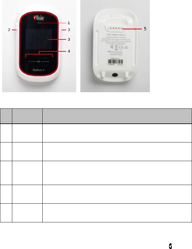
Radius-7 Instrument Module
The Instrument Module connects both optical and acoustic rainbow sensors and has a
Bluetooth radio to connect with Root.
Front View
The following table describes the features of the Instrument Module:
Ref.
Feature Description
1 Acoustic Sensor
Connector
An acoustic sensor can be connected to Radius-7 via this
connector.
CAUTION: Refer to the Directions for Use
for the sensor before
applying it on patients.

Radius-7 Chapter 2- System Components
www.masimo.com 32 Masimo
Ref.
Feature Description
2 Contact Pins The pins provide a data and power connection to the Battery
Module.
3 Key for Armband The key allows for proper positioning of the Armband used to
secure Radius-7 to the patient.
4 rainbow SET Sensor
Connector A rainbow SET sensors can be connected to Radius-7 via this
connector.
CAUTION: Refer to the Directions for Use
for the sensor before
applying it on patients.
Radius-7 Chapter 2- System Components
www.masimo.com 33 Masimo
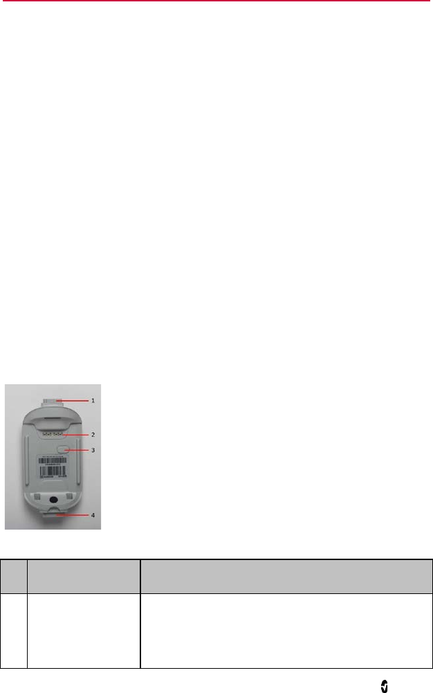
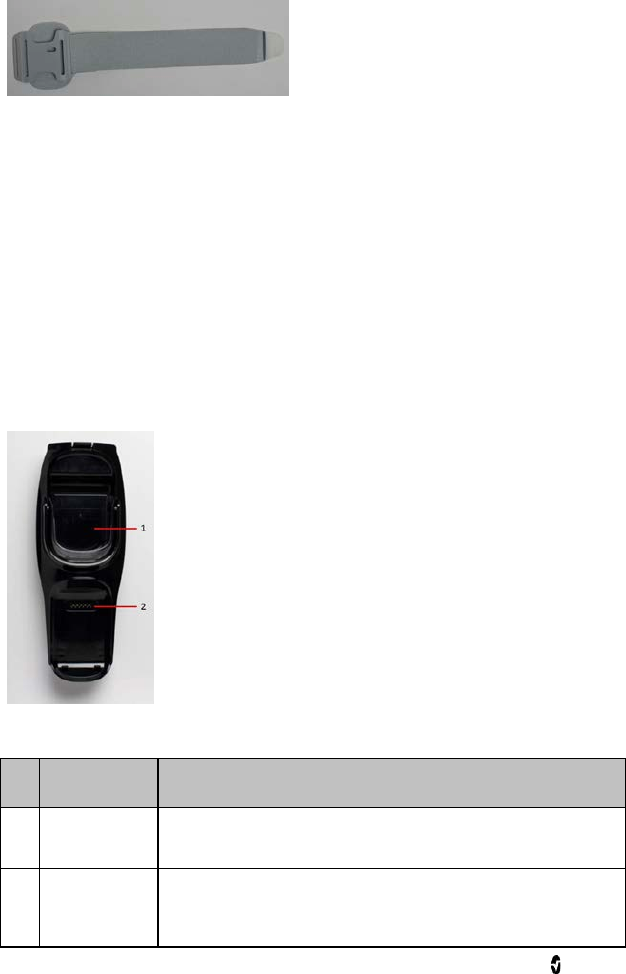
Radius-7 Battery Module
The Battery Module features a Display panel, Touchpad, Speaker and rechargeable
lithium-ion battery. The Battery Module is designed to snap onto the Instrument Module.
Front View Back View
The following table describes the features of the Battery Module:
Ref.
Feature Description
1 Speaker Radius-7 is provided with a speaker to provide alarms in the event the
communication to secondary display is lost.
2 Release
Buttons These buttons are used to release the Battery Module from the
Instrument Module and Battery Charging Adapter.
3 Display
Panel This display area shows parameter values and visual alarms. If the
device is connected to a secondary display, parameter data is displayed
continuously on the secondary display.
4 Touchpad This feature is used to navigate the menu screens and acknowledge
alarms.
5 Connection
Pins The pins enable the Battery Module to dock onto the Battery Charging
Adapter and provide power and communication to the Battery Module.
Radius-7 Chapter 2- System Components
www.masimo.com 34 Masimo
Radius-7 Armband
The Armband is used to secure Radius-7 to the patient. The Armband comes in three different
sizes; small (11.9”), medium (16.4”) and large (25.4”). The Instrument Module and Armband
are keyed so that they can only be connected properly in the right orientation. See Securing
Radius-7 to Patient on page 37 in the Operator's Manual.
Battery Charging Adapter
The Battery Charging Adapter fits into the docking station on Root and allows the Battery
Module to be docked for charging or storage. Once the Battery Charging Adapter is installed
on the Root docking station during initial setup, the adapter should not be removed during
patient monitoring.
Without Battery Module docked
The following table describes the features of the Battery Module:
Ref.
Feature Description
1 Battery Pocket The Battery Pocket can be used to store the entire Radius-7 or
Instrument Module separately.
2 Battery Module
Connector The Battery Module Connector allows for docking and charging of the
Battery Module. See Charging the Radius-7 Battery Module on page 36
in the Operator's Manual.

www.masimo.com 35 Masimo
Chapter 3- Setup
The following chapter contains information about setting up Radius-7 before use.
Unpacking and Inspection
To unpack and inspect the device perform the following steps:
1. Remove the device from the shipping carton and examine it for signs of shipping
damage.
2. Check all materials against the packing list. Save all packing materials, invoice
and bill of lading. These may be required to process a claim with the carrier.
3. If anything is missing or damaged, contact the Technical Service Department. See
Chapter 8 - Service and Maintenance on page 81 of the Operator's Manual.
Preparation for Use
Prior to setting up the Radius-7 for monitoring perform the following steps:
1. Confirm that you have all system components:
• Battery Module (2)
• Instrument Module
• Armband
• Battery Charging Adapter
• Root
• Sensors
2. Read the Safety Information, Warnings and Cautions section of the Operator’s
Manual.
3. Setup the Root system according to the directions provided in the Operator's
Manual for Root.
4. Power on the Root and ensure it is connected to AC power supply. See Operator's
Manual for Root.
5. Ensure the Battery Module is fully charged. See Charging the Radius-7 Battery
Module on page 36 of the Operator’s Manual.

Radius-7 Chapter 3- Setup
www.masimo.com 36 Masimo
Charging the Radius-7 Battery Module
Before use, the Radius-7 Battery Module needs to be fully charged. To charge the Battery
Module for the first time perform the following steps:
1. Attach the Battery Charging Adapter to the Root by aligning the bottom of the
adapter with the two groves at the bottom of the docking interface on the Root
and snap it in place.
2. Ensure that the Root is powered on and connected to an AC power supply.
3. Dock the Battery Module onto the Battery Charging Adapter.
Note: Charge the Battery Module on the Root System you intend to pair with the
Radius-7. Docking the Battery Module onto Root automatically pairs the device
with Root.
4. Verify that the Battery Module is charging. A battery icon will be displayed on the
Radius-7 screen to indicate that the Battery Module is charging. See Battery
Operation and Maintenance on page 82 of the Operator's Manual.
5. Once sufficiently charged you may undock the Battery Module by pressing the
Release Buttons on the Battery Module.
6. Enable Bluetooth Connectivity on Root. See Operator's Manual for Root.
Connecting Radius-7 to Root via Bluetooth
In order connect the Radius-7 to Root via Bluetooth connection perform the following steps:
1. Enable Bluetooth Connectivity on Root. See Operator's Manual for Root.
2. Dock the Battery Module of the Radius-7 to the Root that you intend to make the
Bluetooth connection.
3. Allow enough time for the Root to acknowledge the Radius-7 is docked. The user
will hear a beep tone to indicate that the Bluetooth connection between Root and
Radius-7 been has been established.
4. Verify that the Bluetooth Mac address on Radius-7 matches the Mac Address listed
on Root. See Navigating the Main Menu on page 42 in the Operator’s Manual.
5. Undock the Battery Module from Root and connect it to the Instrument Module to
complete Bluetooth connection.
6. You can verify the Bluetooth connection is successful when the Root screen begins
to display the Radius-7’s measurement data.
WARNING: When the Radius-7 is connected via Bluetooth to Root all audible
alarms will be provided on the Root.
CAUTION: In order to maintain Bluetooth connectivity with Root, ensure that the
Radius-7 is within approximately a 7 m radius and line of sight of Root.
CAUTION: When using multiple Radius-7 and Root systems, re-dock the Battery
Module to Root to ensure proper pairing before connecting the Radius-7 to the
patient.
Radius-7 Chapter 3- Setup
www.masimo.com 37 Masimo
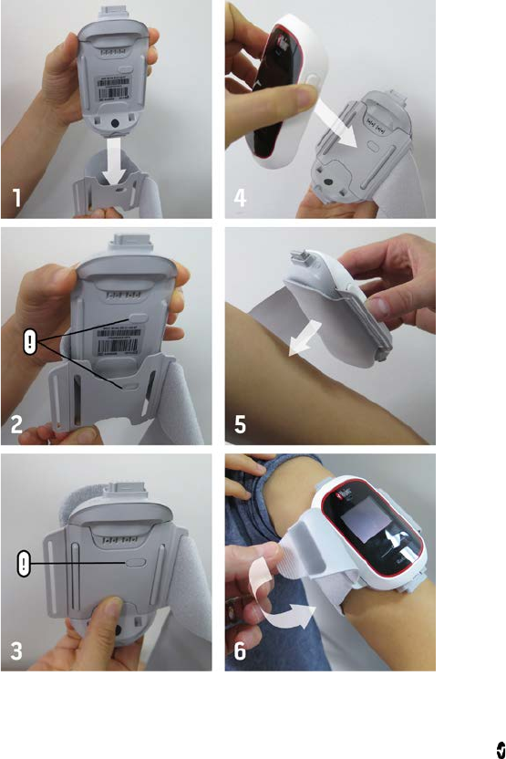
Securing Radius-7 to Patient
Before securing Radius-7 onto the patient, make sure the Battery Module is sufficiently
charged. Note: Safety Information, Warnings and Cautions should be read before use.
See Chapter 2- System Components on page 31 in the Operator’s Manual for information on
the different components.
To secure the Radius-7 to a patient, follow the instructions below with the help of the visual
aid:

Radius-7 Chapter 3- Setup
www.masimo.com 38 Masimo
1. Remove the Armband from the packaging.
2. Slide the Instrument Module between the Armband fabric and the Armband
plastic as shown in the figure above.
3. The shaped hole in the Armband plastic should fit over the matching key
on the front side of the Instrument Module.
4. Connect the Battery Module securing the Armband Adapter between the Battery
Module and the Instrument Module.
5. Select a site on the patient's arm to secure Radius-7. Place the Radius-7 on the
arm with the Masimo logo on the top and making sure the Armband fabric is
between the Radius-7 and the arm.
CAUTION: If the device is being applied directly to the patient's skin, select a site
that is free from skin irritation or signs of chaffing.
CAUTION: Only the smooth side of the Armband fabric should make contact with
the patient when properly applied.
Note: The Radius-7 should be oriented so that the Acoustic Sensor connector is
the closest connector to the patient's neck.
6. Loop the Armband strap around the patient's arm and thread the strap through
the remaining open slot of the Armband plastic from the rear and secure the end
of the Armband strap by pressing the tab on the end onto the Armband fabric.
7. Check to ensure the strap fits comfortably around the patient's arm.
WARNING: Armbands applied too tightly or that become tight due to edema will
cause inaccurate readings and can cause pressure injury.
WARNING: The Armband site must be checked frequently or per clinical protocol
to ensure adequate securement, circulation and skin integrity.
WARNING: Discontinue and dispose of Armband if it appears to be stained or
becomes excessively moist to minimize risk of skin irritation.
CAUTION: Ensure that the Armband does not slide off the arm.
8. Connect sensor(s) to the Instrument Module.
9. See Directions for Use for each sensor for proper application of the sensor to the
patient.
WARNING: As with all medical equipment, carefully route patient cabling to
reduce the possibility of patient entanglement or strangulation.

Radius-7 Chapter 3- Setup
www.masimo.com 39 Masimo
Removing Radius-7 from Patient
To remove the Radius-7 from a patient, perform the following steps:
1. Disconnect sensor(s) from the Instrument Module.
2. Detach the end of the Armband strap from the Armband fabric.
3. Un-thread Armband strap from Instrument Module slot and remove the Radius-7
from the patient’s arm.
4. Press the Release Buttons on the Battery Module, and slide the Battery Module off
of the Instrument Module.
5. Undo the key of the Armband plastic and slide the Instrument Module away from
the Armband.
6. Dispose of the Armband according to local laws and regulations.
WARNING: Do not reuse the strap to avoid possible cross contamination.
7. Disinfect and clean the Battery Module and Instrument Module. See Cleaning on
page 81 of the Operator's Manual.
8. Return the Battery Module to the battery charging adapter for charging. See
Charging the Radius-7 Battery Module on page 36 of the Operator's Manual.
9. Store the Instrument Module in the Battery Pocket of the Battery Charging
Adapter.

www.masimo.com 41 Masimo
Chapter 4- Operation
Using the Touchpad
The Touchpad on the Radius-7 is located below the display panel on the Battery Module.
Note: The display panel is not a touch screen.
Using the gestures described below, the user is able to view all parameters and
measurements, navigate through menu options, and silence/acknowledge alarms on
Radius-7.
Action Description Function
Touch Touch and release. Action
performed once finger is released. Select a menu item or action
Touch
and Hold Touch and stay for a prescribed
amount of time. Release finger
once action had been performed.
Enter and Exit the Main Screen
Silence/acknowledge alarms.
Swipe Touch, move (left, right, up or
down) and release. View all selectable menu options.
Flick Touch, quickly swipe across (left,
right, up or down) and release. View all selectable menu options. Similar to
the Swipe gesture. It allows user to scroll
through menu options faster.
After 30 seconds of inactivity on the Touchpad, the Display Panel turns off automatically and
switches to Standby mode to conserve power. To turn the Display Panel back on, tap
anywhere on the Touchpad.
Note: The Radius-7 display entering Standby mode does not affect the monitoring of the
patient.

Radius-7 Chapter 4- Operation
www.masimo.com 42 Masimo
About the Main Screen
The Main Screen is composed of the following:
Ref
Feature Description
1 Status Bar Visible at the top of the Main Screen and displays Exception Messages,
Bluetooth connectivity status and battery life.
2 Parameter
Display Majority portion of Main Screen. Displays up to four parameters
simultaneously.
3 Waveform
Field Displays SIQ and the pleth waveform with the respiration waveform
(blue) in the background.
Navigating the Main Menu
From the Main Screen, touch and hold the Touchpad to access the Main Menu.
Use the Touchpad Swipe gesture to scroll through the Main Menu Options. Use the Touch
gesture to select the Main Menu Option. Use the same gestures to adjust settings.
The Main Menu options are:
Main Menu
Options Description Default Options
Waveform Allows the user to choose if the waveform will be
displayed on the screen. Off On or Off
Brightness Change the brightness of the Display Panel. 100% 25%, 50%, 75%
and 100%
About Hardware and software information about the
device including Bluetooth Mac Address . N/A N/A

Radius-7 Chapter 4- Operation
www.masimo.com 43 Masimo
Navigating Radius-7 Settings on Root
The following settings on Radius-7 can be configured with Root:
• Sensitivity Mode settings
• Parameter Alarm settings
• In vivo settings
• Additional settings including Averaging time and FastSat.
The following section describes how Radius-7 settings may be configured with Root when
connected via Bluetooth. See Connecting Radius-7 to Root via Bluetooth on page 36 of the
Operator’s Manual for information on how to pair Radius-7 with Root. For general information
on Root, see Operator’s Manual for Root
Configuring Sensitivity Modes
There are two ways to access sensitivity settings menu on Root:
1. From the Main Screen on Root, press on the Sensitivity icon displayed on the top
of the screen to toggle through sensitivity configuration options.
Or
2. Press the gear icon on the bottom right-hand corner of the Main Screen on Root to
access the Main Menu, press the Rainbow tile to access the Rainbow menu. In the
Rainbow menu select the Additional Settings tile to select Sensitivity Mode.
Options Description Factory
Default Configuration
Options
Sensitivity
Modes Defines the sensitivity level for which
the device will operate. See Sensitivity
Modes on page 30 of the Operator's
Manual.
APOD MAX, APOD, or
NORM
Configuring Parameters
Each parameter displayed on Root and Radius-7 can be configured in its respective menu on
Root. Configurable options include Alarm Settings, In Vivo Adjustment, and Averaging Time.
There are two ways to access any parameter’s settings menu on Root:
1. From the Main Screen on Root, press on any of the parameters displayed in the
rainbow window to access its respective settings menu.
Or
2. Press the gear icon on the bottom right-hand corner of the Main Screen on Root to
access the Main Menu. Then press the Rainbow tile to access the Rainbow menu.

Radius-7 Chapter 4- Operation
www.masimo.com 44 Masimo
In the Rainbow menu select the Parameter tile to see all available parameters to
be configured, and finally press any parameter tile to access the settings menu for
that parameter.
Each parameter’s settings menu may include the following options:
Option Description
About A brief explanation about the parameter.
Alarms Configure high/low alarm limits, caution ranges for SpO2, Rapid Desat limit
threshold, alarm delay, Adaptive Threshold Alarm. See Adaptive Threshold
Alarm (ATA) on page 29 of the Operator’s Manual.
In Vivo For SpO2, SpHb, SpCO, SpMet only enable In Vivo Adjustment and set the
offset amount. See In Vivo Adjustment™ on page 27 of the Operator’s Manual.
Additional
Settings
For SpO2, PI, PVI, SpHb and RRa configure averaging time and other settings.

Radius-7 Chapter 4- Operation
www.masimo.com 45 Masimo
SpO2 Settings
About
An informational read-only screen appears with an explanation about SpO2.
Alarms
Option Description Factory
Default Configuration
Options
High Limit High Limit is the upper threshold that triggers
an alarm. Off 2% to 99% in
steps of 1%, or
Off
When set to Off,
alarm is disabled
Low Limit Low Limit is the lower threshold that triggers
an alarm. 88% 1% to 98% in
steps of 1%
Rapid Desat Sets the Rapid Desat limit threshold to the
selected amount below the Low Alarm Limit.
When SpO2 value falls below rapid desat limit
the audio and visual alarm are immediately
triggered without respect to the alarm delay.
-10% -5%, or -10%, or
Off
Alarm Desat When an alarm condition is met, this feature
delays the audible part of an alarm 5
seconds 0, 5, 10, or 15
seconds
Adaptive
Threshold
Alarm (ATA)
ATA establishes patient-specific limit
thresholds based upon the baseline value of
the parameter.
See Adaptive Threshold Alarm (ATA) on page 29
of the Operator's Manual.
Off On or Off
In Vivo
Option Description Factory
Default Configuration Options
Enabled See In Vivo Adjustment™ on page 27
of the Operator's Manual. Off On or Off
Offset
Amount See In Vivo Adjustment™ on page 27
of the Operator's Manual. 0 when
turned On Adjust difference of ± 6%,
in steps of 0.1%

Radius-7 Chapter 4- Operation
www.masimo.com 46 Masimo
Additional Settings
Option Description Factory
Default Configuration
Options
Averaging
Time The length of time over which the system
calculates the average of all data points. 8
seconds 2-4, 4-6, 8, 10,
12, 14 or 16
seconds
FastSat Enable/disable FastSat feature for rapid tracking
of oxygen saturation changes. When enabled, the
averaging algorithm evaluates all saturation
values, providing an averaged saturation value
that is a better representation of the patient's
current oxygenation status.
Off On or Off
PR Settings
About
An informational read-only screen appears with an explanation about PR.
Alarms
Option Description Factory
Default Configuration Options
High
Limit High Limit is the upper threshold
that triggers an alarm. 140 bpm 35 bpm to 235 bpm, in
steps of 5 bpm
Low
Limit Low Limit is the lower threshold that
triggers an alarm. 50 bpm 30 bpm to 230 bpm, steps
of 5 bpm

Radius-7 Chapter 4- Operation
www.masimo.com 47 Masimo
PI Settings
About
An informational read-only screen appears with an explanation about PI.
Alarms
Option Description Factory
Default Configuration Options
High
Limit High Limit is the upper threshold that
triggers an alarm. Off Step size:
0.04 to 0.09 in steps of
0.01
0.10 to 0.90 in steps of
0.10
1 to 19 in steps of 1, or
Off
Low
Limit Low Limit is the lower threshold that
triggers an alarm. Off Step size:
0.03 to 0.09 in steps of
0.01
0.10 to 0.90 in steps of
0.10
1 to 18 in steps of 1, or
Off
Additional Settings
Option Description Factory
Default Configuration
Options
Averaging
Time The length of time over which the system
calculates the average of all data points. Long Short or Long

Radius-7 Chapter 4- Operation
www.masimo.com 48 Masimo
PVI Settings
About
An informational read-only screen appears with an explanation about PVI.
Alarms
Option Description Factory
Default Configuration Options
High
Limit High Limit is the upper threshold that
triggers an alarm. Off 2 to 99 in steps of 1, or Off
When set to Off, alarms are
disabled.
Low
Limit Low Limit is the lower threshold that
triggers an alarm. Off 1 to 98 in steps of 1, or Off
When set to Off, alarms are
disabled.
Additional Settings
Option Description Factory
Default Configuration
Options
Averaging
Time The length of time over which the system
calculates the average of all data points. Long Short or Long

Radius-7 Chapter 4- Operation
www.masimo.com 49 Masimo
SpHb Settings
About
An informational read-only screen appears with an explanation about SpHb.
Alarms
Option Description Factory
Default Configuration Options
High
Limit High Limit is the upper
threshold that triggers an
alarm.
17.0 g/dL
(11.0
mmol/L)
2.0 g/dL to 24.5 g/dL in steps of 0.1
g/dL, or Off
(2.0 mmol/L to 15.0 mmol/L in steps of
0.1 mmol/L, or Off)
When SpHb Precision is set to 1.0, the
values are rounded to the nearest whole
number.
When set to Off, alarm is disabled.
Low
Limit Low Limit is the lower
threshold that triggers an
alarm.
7.0 g/dL
(4.0
mmol/L)
1.0 g/dL to 23.5 g/dL in steps of 0.1
g/dL. or Off
(1.0 mmol/L to 14.5 mmol/L, in steps of
0.1 mmol/L, or Off)
When SpHb Precision is set to 1.0,
values are rounded to the nearest whole
number.
When set to Off, alarm is disabled.
In Vivo
Option Description Factory
Default Configuration
Options
In Vivo
Calibration See In Vivo Adjustment™ on page 27
of the Operator's Manual. Off On or Off
In Vivo
Calibration Offset See In Vivo Adjustment™ on page 27
of the Operator's Manual. 0 when
turned On ± 3 g/dL in steps of ±
0.1 g/dL

Radius-7 Chapter 4- Operation
www.masimo.com 50 Masimo
Additional Settings
Option Description Factory
Default Configuration
Options
Averaging
Time The length of time over which the system
calculates the average of all data points. Medium Short, Medium, or
Long
Calibration Provides an arterial or venous value that
displays on the main screen. Venous Arterial or Venous
Precision Allows the user to set the decimal for
SpHb. 0.1 0.1, 0.5, or 1.0
(whole numbers)
Unit of
Measure Displays total hemoglobin (SpHb) as g/dL
(grams per deciliter) or mmol/L
(millimoles per liter).
g/dL mmol/L or g/dL

Radius-7 Chapter 4- Operation
www.masimo.com 51 Masimo
SpCO Settings
About
An informational read-only screen appears with an explanation about SpCO
Alarms
Option Description Factory
Default Configuration Options
High
Limit High Limit is the upper threshold that
triggers an alarm. 10
2% to 98%, in steps of 1%,
or Off
When set to Off, alarm is
disabled
Low
Limit Low Limit is the lower threshold that
triggers an alarm. Off 1% to 97%, in steps of 1%,
or Off
When set to Off, alarm is
disabled.
In Vivo
Option Description Factory
Default Configuration
Options
Enabled See In Vivo Adjustment™ on page 27 of the
Operator's Manual. Off On or Off
Offset
Amount See In Vivo Adjustment™ on page 27 of the
Operator's Manual. 0 when
turned On ± 9% in steps of ±
0.1%

Radius-7 Chapter 4- Operation
www.masimo.com 52 Masimo
SpMet Settings
About
An informational read-only screen appears with an explanation about SpMet
Alarms
Option Description Factory
Default Configuration Options
High
Limit High Limit is the upper threshold that
triggers an alarm. 10
1% to 2%, in steps of 0.1%,
2.5% to 99.5% in steps of
0.5%, or Off
When set to Off, alarm is
disabled
Low
Limit Low Limit is the lower threshold that
triggers an alarm. Off 0.1% to 2%, in steps of 0.1%
2.5% to 99%, in steps of
0.1%, or Off
When set to Off, alarm is
disabled.
In Vivo
Option Description Factory
Default Configuration
Options
Enabled See In Vivo Adjustment™ on page 27 of the
Operator's Manual. Off On or Off
Offset
Amount See In Vivo Adjustment™ on page 27 of the
Operator's Manual. 0 when
turned On ± 3% in steps of ±
0.1%

Radius-7 Chapter 4- Operation
www.masimo.com 53 Masimo
SpOC Settings
About
An informational read-only screen appears with an explanation about SpOC
Alarms
Option Description Factory
Default Configuration Options
High
Limit High Limit is the upper threshold that
triggers an alarm. Off
2% to 34%, in steps of 1%,
or Off
When set to Off, alarm is
disabled
Low
Limit Low Limit is the lower threshold that
triggers an alarm. Off 1% to 33%, in steps of 1%,
or Off
When set to Off, alarm is
disabled.
Respiration Rate Settings
The Radius-7 can determine respiration rate (RR) either by the acoustic signal (RRa) or by the
plethysmographic waveform (RRp).

Radius-7 Chapter 4- Operation
www.masimo.com 54 Masimo
RRa Settings
When using an acoustic sensor, respiration rate (RR) is determined by the acoustic (RRa)
signal. See rainbow Acoustic Monitoring™ (RAM™) on page 25 of the Operator's Manual. When
the respiratory rate is determined by the acoustic signal, RRa alarms and RRa settings are
active, and the parameter label displays as RRa.
RRa is active under the following conditions:
• RRa is installed on Radius-7.
• Acoustic sensor is connected.
About
An informational read-only screen appears with an explanation about RRa
Alarms
Option Description Factory
Default Configuration Options
High Limit High Limit is the upper threshold
that triggers an alarm. 30 breaths
per minute 6 to 69 breaths per minute
in steps of 1 breath per
minute, or Off
Low Limit Low Limit is the lower threshold
that triggers an alarm. 6 breaths
per minute 5 to 68 breaths per minute
in steps of 1 breath per
minute, or Off
Respiratory
Pause The duration of time that triggers
an alarm if no breaths are
detected
30 seconds 15, 20, 25,30, 35, or 40
seconds
Alarm Delay When a High or Low alarm
condition occurs, this feature
delays the audible part of an
alarm
30 seconds 0, 10, 15, 30 or 60 seconds
Additional Settings
Option Description Factory
Default Configuration
Options
Averaging
Time The length of time over which the system
calculates the average of all data points. Slow No, Fast, Medium,
Slow or Trending

Radius-7 Chapter 4- Operation
www.masimo.com 55 Masimo
Option Description Factory
Default Configuration
Options
Freshness The duration of time that, during
interference, the system displays the last
valid reading.
5 minutes 0, 1, 5, 10, or 15
minutes

Radius-7 Chapter 4- Operation
www.masimo.com 56 Masimo
RRp Settings
When using a pulse oximetry or pulse CO-Oximetry sensor with Radius-7, respiration rate can
be determined by the plethysmographic waveform (RRp). This method measures a patient's
respiratory rate based on plethysmographic amplitude changes that correspond to the
respiratory cycle. When using a pulse oximetry or pulse CO-Oximetry sensor, RRp alarms and
RRp settings are active and the parameter label displays as RRp.
Note that the Radius-7 can monitor RRa or RRp but not both simultaneously. RRp is active
under the following conditions:
• RRp is installed on the Radius-7.
• Pulse oximetry or pulse CO-Oximetry sensor is connected.
• Acoustic sensor is not connected.
About
An informational read-only screen appears with an explanation about RRp
Alarms
Option Description Factory
Default Configuration Options
High
Limit High Limit is the upper threshold
that triggers an alarm. 30 breaths
per minute
6 to 69 breaths per minute in
steps of 1 breath per minute,
or Off
Low
Limit Low Limit is the lower threshold
that triggers an alarm. 6 breaths
per minute 5 to 68 breaths per minute in
steps of 1 breath per minute,
or Off
Alarm
Delay When a High or Low alarm condition
occurs, this feature delays the
audible part of an alarm
30 seconds 0, 10, 15, 30 or 60 seconds
Additional Settings
Option Description Factory
Default Configuration
Options
Averaging
Time The length of time over which the system
calculates the average of all data points. Slow No, Fast, Medium,
Slow or Trending

Radius-7 Chapter 4- Operation
www.masimo.com 57 Masimo
Option Description Factory
Default Configuration
Options
Freshness The duration of time that, during
interference, the system displays the last
valid reading.
5 minutes 0, 1, 5, 10, or 15
minutes
www.masimo.com 59 Masimo
Chapter 5- Alarms and Messages
About Alarms
The Radius-7 visually and audibly indicates alarm conditions that the system detects. Audible
alarms may be silenced, without affecting the operation of visual alarms. See Safety
Information, Warnings and Cautions on page 11.
Alarm Priorities
There are two priorities for alarms:
• High
• Medium
The following are the audible and visual characteristics for different alarm priorities:
Alarm Priority Audible Characteristics Visual Characteristics
High 571 Hz tone, 10 pulse bursts Flashing Red
Medium 550 Hz tone, 3 pulse bursts Flashing Yellow
The conditions and priorities are provided below:
Parameter
High Limit Alarm Low Limit Alarm
SpO2 Medium High
PR High High
PI Medium Medium
SpCO High Medium
SpMet High Medium
SpHb High High
SpOC Medium High
PVI Medium Medium
RRa High High
RRp High High

Radius-7 Chapter 5- Alarms and Messages
www.masimo.com 60 Masimo
Alarm Management
In order to minimize accidental changes to Radius-7's critical settings, alarm management is
restricted to Root.
When Radius-7 is connected to Root, audible alarms will sound on Root but not Radius-7. In
this case, audible alarms can be temporarily silenced on Root. Visual alarms will display on
both Radius-7 and Root until the alarm condition has been addressed. For alarm
management on Root, see Operator’s Manual for Root.
When Radius-7 is not connected to Root, audible alarms will sound on Radius-7. Audible
alarms can be temporarily silenced by touching and holding the Touchpad for 2 seconds.
Visual alarms will continue to display on Radius-7 until the alarm condition has been
addressed.
The following are the factory default settings and configuration options for Alarms:
Option Description Factory
Default
Setting
Configurable Settings on Root
Alarm
Volume Sets the alarm volume level. Highest
volume Slide towards the left to decrease
volume to silence.
Pulse Tone
Volume Sets the pulse tone volume
level. Highest
volume Slide towards the left to decrease
volume to silence.
Audio
Pause
Duration
Sets the length of time that
the audible alarm remains
silenced, when Audio Pause
is enabled.
2 minutes
1, 2, 3 minutes, Permanent*,
Permanent with Reminder*.
If Permanent is selected, there will
be no audible alarms, but visual
alarms will still display.
If Permanent with Reminder is
selected, a tone will sound every
three (3) minutes as a reminder
that Permanent is active.
*Requires user to have All Mute
Enabled in the Access Control
menu. See Operator's Manual for
Root.
Note: In the event of temporary loss of power to Radius-7, the Root will restore alarm setting
to Radius-7 through the re-established Bluetooth connection. If the Radius-7 is used without
a Bluetooth connection to Root, then the alarm settings will be restored to the factory
default.

Radius-7 Chapter 5- Alarms and Messages
www.masimo.com 61 Masimo
Messages
The following section lists common messages, their potential causes, and next steps.
Alarm Message Description Next Step
Low battery Battery charge is low. Charge Battery Module by
docking into Battery
Charging Adapter on Root
and powering Root with
AC line power. Replace
Battery Module if
necessary.
Device disconnected Device has lost Bluetooth
connectivity with Root. Check if Bluetooth is
enabled on Root. See the
Operator's Manual for
Root.
Check connection
between the Instrument
Module and Battery
Module.
Redock the Battery
Module on Root to
re-establish Bluetooth
connectivity.
Speaker failure message Device requires service. Contact Masimo Tech
Support. See Contacting
Masimo on page 84 of the
Operator’s Manual.
• (Pulse CO-Ox)
Replace
Sensor, or
• (RAM) Replace
Sensor
Reusable sensor has used all of its
available monitoring time
• Sensor is non-functional.
• Defective sensor.
Replace sensor.
• (Pulse CO-Ox)
Incompatible
Sensor, or
• (RAM)
Incompatible
Sensor
Not a compatible Masimo sensor. Replace with a compatible
Masimo sensor.
Sensor is attached to a device
without an appropriate parameter
installed.
Use a compatible sensor.
Contact your local Masimo
Representative to learn
more about optional
parameter upgrades.

Radius-7 Chapter 5- Alarms and Messages
www.masimo.com 62 Masimo
Alarm Message Description Next Step
• (Pulse CO-Ox)
Replace
Adhesive
Sensor, or
• (RAM) Replace
Adhesive
Sensor
When a single-patient-use sensor is
used, the adhesive portion of the
sensor is non-functional, or the life
of the adhesive portion of the sensor
has expired.
Replace the adhesive
portion of the sensor.
• (Pulse CO-Ox)
Replace Cable,
or
• (RAM) Replace
Cable
Defects in the Instrument Module Return the device for
servicing.
• (Pulse CO-Ox)
Incompatible
Adhesive
Sensor, or
• (RAM)
Incompatible
Adhesive
Sensor
Not a compatible Masimo Adhesive
sensor. Replace with a compatible
Masimo sensor.
Sensor is attached to a device
without an appropriate parameter
installed.
Use a compatible sensor.
Contact your local Masimo
Representative to learn
more about optional
parameter upgrades.
• (Pulse CO-Ox)
No Adhesive
Sensor
Connected, or
• (RAM) No
Adhesive
Sensor
Connected
When a single-patient-use sensor is
used, the adhesive portion of the
sensor is not connected.
Ensure the adhesive
portion is firmly
connected to the sensor.
• (Pulse CO-Ox)
Interference
Detected, or
• (RAM)
Interference
Detected
High intensity light such as
pulsating strobe lights, excessive
ambient light sources such as
surgical lights or direct sunlight, or
other monitor displays.
Place a Masimo Optical
Light Shield over the
sensor.
(Pulse CO-Ox) Low
Perfusion Index Signal too small. Move sensor to better
perfused site.

Radius-7 Chapter 5- Alarms and Messages
www.masimo.com 63 Masimo
Alarm Message Description Next Step
(Pulse CO-Ox) Low Signal
IQ Low signal quality. Ensure proper sensor
application. Move sensor
to a better perfused site.
See Signal IQ® (SIQ) on
page 28 of the Operator’s
Manual.
Low SpCO SIQ message SpCO measurement reading is
obscured. Ensure proper sensor
application. Check sensor
to see if it is working
properly. If not, replace
the sensor.
Low SpMet SIQ message SpMet measurement reading is
obscured. Ensure proper sensor
application. Check sensor
to see if it is working
properly. If not, replace
the sensor.
Low SpHb SIQ message SpHb measurement reading is
obscured. Ensure proper sensor
application. Check sensor
to see if it is working
properly. If not, replace
the sensor.
• (Pulse CO-Ox)
No Sensor
Connected, or
• (RAM) No
Sensor
Connected
Sensor not fully inserted into the
connector. Disconnect and reconnect
sensor. See the
instructions for use
provided with your sensor.
Incompatible or defective sensor. Replace with a compatible
Masimo sensor.
Device is searching for patient’s
pulse. Disconnect and reconnect
the sensor to the
Instrument Module.
(Pulse CO-Ox) Pulse
Search Device is searching for pulse. If device fails to display
within 30 seconds,
disconnect and reconnect.
If pulse search continues,
move sensor to better
perfused site.

Radius-7 Chapter 5- Alarms and Messages
www.masimo.com 64 Masimo
Alarm Message Description Next Step
(Pulse CO-Ox) Sensor
Initializing
Device is checking the sensor for
proper functioning and
performance.
If values are not displayed
within 30 seconds,
disconnect and reconnect
sensor. If values are still
not displayed, replace
with a new sensor.
• (Pulse CO-Ox)
Sensor Off
Patient, or
• (RAM) Sensor
Off Patient
Sensor off patient. Disconnect and reconnect
sensor. Reattach sensor.
Sensor not connected to patient
properly. Sensor is damaged. Properly reapply the
sensor on the patient and
reconnect the sensor to
the Instrument Module. If
the sensor is damaged,
replace the sensor.

www.masimo.com 65 Masimo
Chapter 6- Troubleshooting
Troubleshooting Measurements
Symptom Potential Causes Next Steps
Low signal
quality. Sensor is damaged or
not functioning.
Improper sensor type
or application.
Excessive motion.
Low perfusion.
• Verify Sensor type and size and
re-apply sensor. See Directions for Use
for Sensor.
• Check and see if blood flow to the site
is restricted.
• Check the placement of the sensor.
Re-apply sensor or move to a different
site.
• Replace Sensor.
• Minimize or eliminate motion at the
monitoring site.
• Set to Maximum Sensitivity. See
Sensitivity Modes on page 30 of the
Operator's Manual.
Difficulty
obtaining a
reading.
Interference from line
frequency induced
noise.
Misaligned sensor
Inappropriate sensor or
sensor size.
Excessive ambient or
strobing light.
Excessive motion.
• Verify/set 50/60hz menu setting. See
Operator's Manual for Root.
• Verify Sensor type and size and
re-apply sensor. See Directions for Use
for Sensor.
• Check and see if blood flow to the site
is restricted.
• Check the placement of the sensor.
Re-apply sensor or move to a different
site.
• Minimize or eliminate motion at the
monitoring site.
• Shield the sensor from excessive or
strobing light.

Radius-7 Chapter 6- Troubleshooting
www.masimo.com 66 Masimo
Symptom Potential Causes Next Steps
SpCO reading
displays as
dashes.
SpCO parameter may
have not stabilized.
• Allow time for parameter reading to
stabilize.
• Verify Sensor type and size and
re-apply sensor. See Directions for Use
for Sensor.
• Check and see if blood flow to the site
is restricted.
• Check the placement of the sensor.
Re-apply sensor or move to a different
site.
• Replace Sensor.
• Submit blood sample for laboratory
CO-Oximetry test for comparison.
• Check patient conditions indicated to
affect SpCO accuracy.
Troubleshooting Radius-7
Symptom Potential
Cause Next Step
Device turns on
but Display Panel
is blank.
The viewing
contrast is
not correct.
Adjust the brightness setting. See Navigating the Main
Menu on page 42 of the Operator’s Manual. If the
condition persists, issue requires service. See Contacting
Masimo on page 84 of the Operator’s Manual
Touchpad does
not respond to
gestures.
Internal
failure. Requires service. See Contacting Masimo on page 84 of the
Operator’s Manual.
Speaker makes
no sound when
device is not
connected to
Root.
Internal
failure Requires service. See Contacting Masimo on page 84 of the
Operator’s Manual.

Radius-7 Chapter 6- Troubleshooting
www.masimo.com 67 Masimo
Symptom Potential
Cause Next Step
Unable to pair
with Root Bluetooth
not enabled
on Root.
Internal
failure.
1. Check if Bluetooth is enabled on Root. See the
Operator's Manual for Root.
2. Check if Bluetooth is enabled on Radius-7 by
accessing the About panel on the Main Menu.
See Connecting Radius-7 to Root via Bluetooth
on page 36 of the Operator's Manual.
3. Verify the Mac address on Radius-7 matches the
one on Root. The Mac address on Radius-7 can
be found by accessing the About panel on the
Main Menu of Radius-7. For information on
accessing the Mac address listed on Root refer
to Operator's Manual for Root.
4. Re-dock the Battery Module on Root to pair the
device with Root.
5. Call Service.
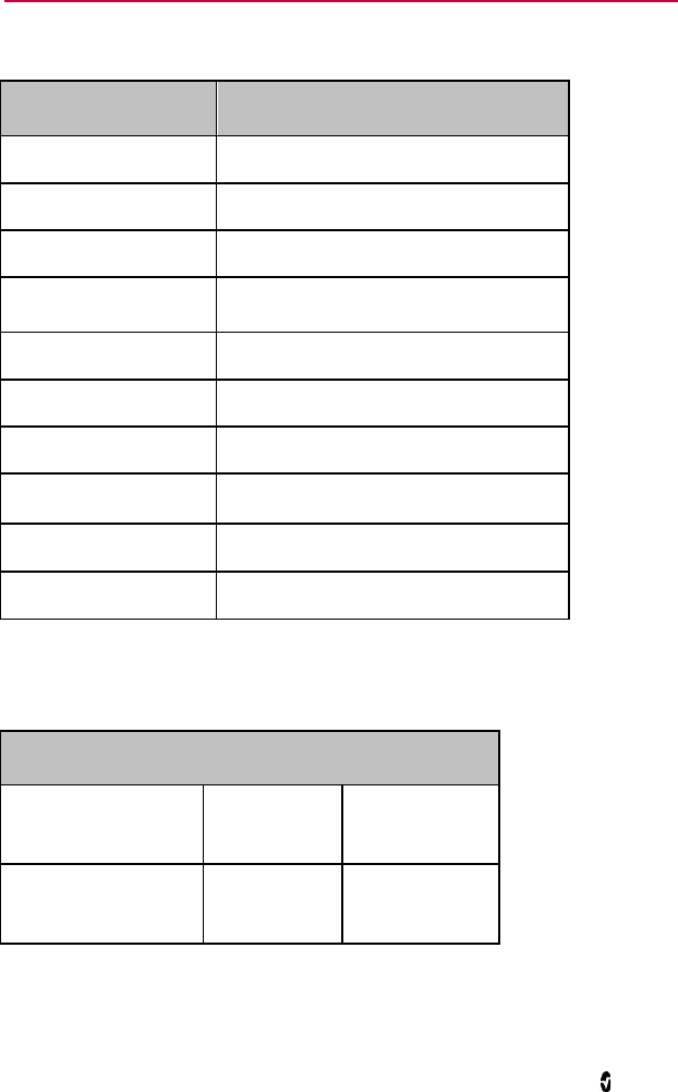
www.masimo.com 69 Masimo
Chapter 7- Specifications
Measurement Range
Measurement Display Range
SpO2 (Oxygen Saturation) 0% to 100%
SpMet (Methemoglobin) 0% to 99.9%
SpCO (Carboxyhemoglobin) 0% to 99%
SpHb (Hemoglobin) 0 g/dL to 25.0 g/dL
SpOC (Oxygen Content) 0 ml of O2/dL to 35 ml of O2/dL of blood
PR (Pulse Rate) 25 bpm to 240 bpm
PI (Perfusion Index) 0.02% to 20%
PVI (Pleth Variability Index) 0% to 100%
RRa (Respiration Rate) 0 breaths per minute to 70 breaths per minute
RRp (Respiration Rate) 0 breaths per minute to 70 breaths per minute
Accuracy
Oxygen Saturation (SpO2) [1]
No Motion [1]
(SpO2 from 60% to 80%) Adults, Pediatrics 3%
No Motion [2]
(SpO2 from 70% to 100%) Adults, Pediatrics 2%

Radius-7 Chapter 7- Specifications
www.masimo.com 70 Masimo
Motion [3]
(SpO2 from 70% to 100%) Adults, Pediatrics 3%
Low perfusion [4]
(SpO2 from 70% to 100%) Adults, Pediatrics 2%
Pulse Rate (PR)
Range 25 to 240 bpm
No motion Adults, Pediatrics 3 bpm
Motion [5] Adults, Pediatrics 5 bpm
Low Perfusion Adults, Pediatrics 3 bpm
Carboxyhemoglobin Level (SpCO) [1]
Range of 1% to 40% Adults, Pediatrics 3%
Methemoglobin Level (SpMet) [1]
Range 1% to 15% Adults, Pediatrics 1%
Total Hemoglobin SpHb [6]
Range of 8 g/dL to 17 g/dL Adults, Pediatrics 1 g/dL
Respiratory Rate (RRa, RRp) [7]
Range of 4 to 70 bpm Adults, Pediatrics 1 breath per minute
Resolution
Parameter Resolution
%SpO2 1%
%SpCO 1%
%SpMet 0.1%

Radius-7 Chapter 7- Specifications
www.masimo.com 71 Masimo
Parameter Resolution
SpHb g/dL 0.1 g/dL
Pulse Rate 1 beats per minute
Respiration Rate
1 breaths per minute
Electrical
Battery Module of Radius-7
Type Lithium ion
Capacity 12 hours
Charging Time ≤ 6 hours
For information on Root Battery see Specifications in the Operator's Manual for Root
Environmental
Radius-7 Environmental Conditions:
Environmental Conditions
Operating Temperature 41°F to 104°F
(5°C to 40°C)
Transport/Storage
Temperature -4°F to 122°F
(-20°C to 50°C) [8]
Operating Humidity 10% to 95%, non-condensing
Non-Operating Humidity 10% to 95%, non-condensing
Operating Altitude 540 mbar to 1060 mbar at ambient temperature and
humidity
For Environmental Specifications for Root with Battery Charging Adapter see Operator's
Manual for Root.

Radius-7 Chapter 7- Specifications
www.masimo.com 72 Masimo
Physical Characteristics
Item Description
Dimensions 5.1” x 2.8 ” x 1.2”
(130 mm x 70 mm x 30 mm)
Weight 0.34lbs. (155g)
Alarms
Parameter Alarm Range
SpO2 1% to 99%
SpCO 1% to 98%
SpMet 0.1% to 99.5%
SpHb 1.0 g/dL to 24.5 g/dL
RR 5 to 69 breaths per minute
PI 0.03% to 19%
PVI 1% to 99%
Pulse Rate 30 bpm to 235 bpm
SpOC 1 g/dL to 34 g/dL
Alarm Characteristic Description
Alarm Volume (Set at 100%)
High Priority
Medium Priority
Medium Priority < High Priority
Sensitivity NORM, MAX, APOD [8]
Radius-7 Chapter 7- Specifications
www.masimo.com 73 Masimo
Display Indicators
Item Description
Trend Memory Max of 6 hours at 2-second resolution
Display Update Rate 1 second
Response Time < 30 second delay
Type OLED
Pixels 160 X 128
Dot Pitch 0.073 (W) mm X 0.219 (H) mm
EMC Compliance
EMC Compliance
IEC 60601-1-2:2007, Class B
Safety Standards Compliance
Safety Standards Compliance
ANSI/AAMI ES 60601-1:2005
CAN/CSA C22.2 No. 60601-1:2008
IEC 60601-1:2005
EN 60601-1:2006
ANSI/AAMI/IEC 60601-1-8:2006
IEC 60601-2-49:2011
EN/ISO 80601-2-61:2011

Radius-7 Chapter 7- Specifications
www.masimo.com 74 Masimo
Equipment Classification per IEC 60601-1
Type of Protection Internally powered (battery powered)
Degree of Protection against
Electrical Shock Defibrillation Proof Type BF-Applied Part
Protection against harm from
Water and Particulate Matter IP24 (Protection from solid foreign objects ≥12.5 mm
diameter and against ingress from splashing water)
Mode of Operation Continuous
Environment Not suitable for use in the presence of flammable
anesthetics
Radio Compliance
Radio Modes
Bluetooth
Compliance
USA FCC ID: VFK-RADIUS
FCC parts 15.247
Canada IC: 7362A-RADIUS
RSS-210
Europe EN 300 328,
EN 301 489-17
R&TTE

Radius-7 Chapter 7- Specifications
www.masimo.com 75 Masimo
Guidance and Manufacturer's Declaration- Electromagnetic
Emissions
Guidance and Manufacturer's Declarations - Electromagnetic Emissions
The ME Equipment is intended for use in the electromagnetic environment specified below. The customer
or the user of the ME Equipment should assure that it is used in such an environment.
Emission
Test Compliance Electromagnetic Environment - Guidance
RF
Emissions
CISPR 11
Group 1
ME Equipment uses RF energy only for its internal function. Therefore, its RF
emissions are very low and are not likely to cause any interference in nearby
electronic equipment.
RF
Emissions
CISPR 11
Class B Suitable for use in all establishments, including domestic environments.
Guidance and Manufacturer's Declaration- Electromagnetic
Immunity
Guidance and Manufacturer's Declaration - Electromagnetic Immunity
The ME Equipment is intended for use in the electromagnetic environment specified below. The
customer or the user of the ME Equipment should assure that it is used in such an environment.
Immunity Test IEC
60601
Test Level
Compliance
Level Electromagnetic Environment - Guidance
Electrostatic
discharge (ESD)
IEC 61000-4-2
+6 kV
contact
+8 kV air
+6 kV
contact
+8 kV air
Floors should be wood, concrete or ceramic tile. If
floors are covered with synthetic material, the relative
humidity should be at least 30%.
Power frequency
(50 / 60 Hz)
magnetic field.
IEC 61000-4-8
3 A/m 3 A/m Power frequency magnetic fields should be at levels
characteristic of typical location in a typical hospital
environment.
Radiated RF
IEC 61000-4-3
3 V/m
80 MHz
to 2.5
GHz
3 V/m
Portable and mobile RF communications equipment
should be used no closer to any part of the ME
Equipment, including cables, than the recommended
separation distance calculated from the equation
applicable to the frequency of the transmitter.
Recommended separation distance
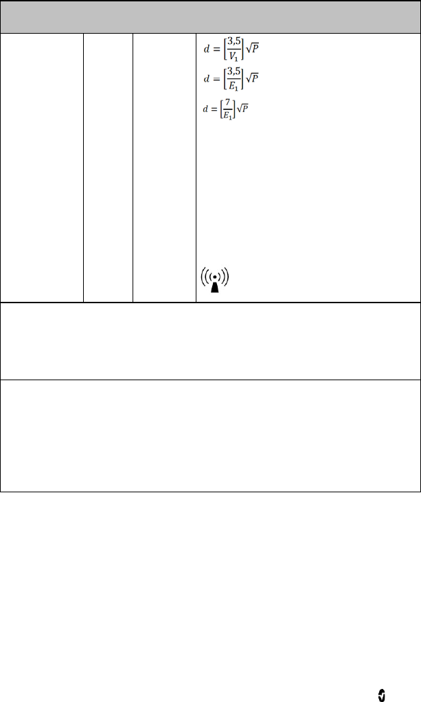
Radius-7 Chapter 7- Specifications
www.masimo.com 76 Masimo
Guidance and Manufacturer's Declaration - Electromagnetic Immunity
80 MHz to 800 MHz
800 MHz to 2,5 GHz
where P is the maximum output power rating of the
transmitter in watts (W) according to the transmitter
manufacturer and d is the recommended separation
distance in meters (m).
Field strengths from fixed RF transmitters, as
determined by an electromagnetic site survey, should
be less than the compliance level in each frequency
rangeb.
Interference may occur in the vicinity of equipment
marked with the following symbol:
Note 1: At 80 MHz and 800 MHz, the higher frequency range applies.
Note 2: These guidelines may not apply in all situations. Electromagnetic propagation is affected by
absorption and reflection from structures, objects and people.
Field strengths from fixed transmitters, such as base stations for radio (cellular/cordless) telephones
and land mobile radios, amateur radio, AM and FM radio broadcast and TV broadcast cannot be
predicted theoretically with accuracy. To assess the electromagnetic environment due to fixed RF
transmitters, an electromagnetic site survey should be considered. If the measured field strength in
the location in which the ME Equipment is used exceeds the applicable RF compliance level above, the
ME Equipment should be observed to verify normal operation. If abnormal performance is observed,
additional measures may be necessary, such as re-orienting or relocating the ME Equipment.
b Over the frequency range 150 kHz to 80 MHz, field strengths should be less than [V1] V/m.

Radius-7 Chapter 7- Specifications
www.masimo.com 77 Masimo
Recommended Separation Distances
Recommended Separation Distance Between Portable and Mobile RF Communication Equipment and
the ME Equipment
The ME Equipment is intended for use in an electromagnetic environment in which radiated RF
disturbances are controlled. The customer or the user of the ME Equipment can help prevent
electromagnetic interference by maintaining a minimum distance between portable and mobile RF
communications equipment (transmitters) and the ME Equipment as recommended below, according to
the maximum output power of the communication equipment.
Rated maximum output power of
transmitter (W) Separation Distance According to Frequency of Transmitter (m)
150 K Hz to 80
MHz
d = 1.17*Sqrt (P)
80 MHz to 800
MHz
d = 1.17*Sqrt (P)
800 MHz to 2.5GHz
d = 2.33*Sqrt (P)
0.01 0.12 0.12 0.23
0.1 0.37 0.37 0.74
1 1.17 1.17 2.33
10 3.7 3.7 7.37
100 11.7 11.7 23.3
For transmitters rated at a maximum output power not listed above, the recommended separation
distance d in meters (m) can be estimated using the equation applicable to the frequency of the
transmitter, where P is the maximum output power rating of the transmitter in watts (W) according to
the transmitter manufacturer.
Note 1: At 80 MHz and 800 MHz, the higher frequency range applies.
Note 2: These guidelines may not apply in all situations. Electromagnetic propagation is affected by
absorption and reflection from structures, objects and people.
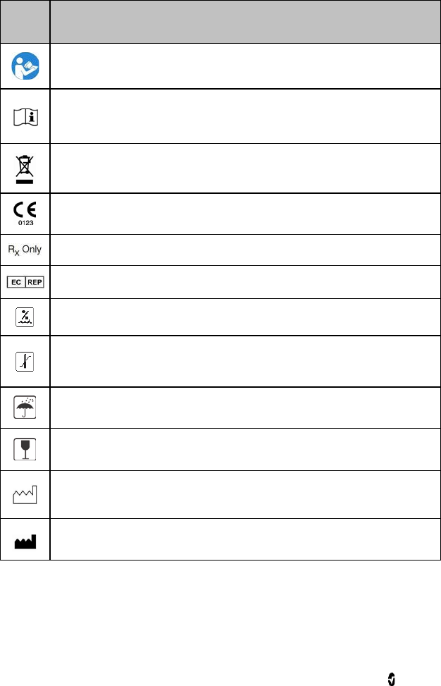
Radius-7 Chapter 7- Specifications
www.masimo.com 78 Masimo
Symbols
Symbol Description
Follow Instructions for Use.
See Instructions for Use.
Separate collection for electronic waste.
Mark of conformity to European Medical Device Directive 93/42/EEC.
Federal law restricts this device to sale by or on the order of a licensed physician.
Authorized Representative in the European Community
Storage Humidity range: 10% to 95% or 15% to 95%.
Storage temperature range: +70° C to -40° C or -20° C to 50° C.
Storage altitude range: +1600hPa to +500hPa.
Keep dry.
Fragile/breakable, handle with care.
Date of Manufacture.
Manufacturer.
Radius-7 Chapter 7- Specifications
www.masimo.com 79 Masimo
Symbol Description
Non-sterile.
Defibrillation proof Type BF.
IP24 Protection from ingress and particulate matter.
Catalog number (model number).
Serial Number.
UL, LLC. Certification.
Non-ionizing electromagnetic radiation.
Federal Communications Commission (FCC) licensing.
Wireless features can be used in member states with the restriction of indoor use
in France.
IC Model Industry Canada Registered Model.

Radius-7 Chapter 7- Specifications
www.masimo.com 80 Masimo
Citations
[1] SpO2, SpCO, and SpMet accuracy was determined by testing on healthy adult male and
female volunteers in the range 60% to 100% SpO2, 0% to 40% SpCO, and 0% to 15% SpMet
against a laboratory CO-Oximeter. SpO2 and SpMet accuracy was determined on 16 neonatal
NICU patients ranging in age from 7 days to 135 days old and weighing between 0.5 kg and
4.25 kg. Seventy-nine data samples were collected over a range of 70% to 100% SaO2 and 0.5%
to 2.5% HbMet with a resultant accuracy of 2.9% SpO2 and 0.9% SpMet. Contact Masimo for
testing specifications.
[2] The Masimo rainbow SET technology with Masimo sensors has been validated for no motion
accuracy in human blood studies on healthy adult male and female volunteers with light to
dark skin pigmentation in induced hypoxia studies in the range of 70%-100% SpO2 against a
laboratory CO-Oximeter and ECG monitor. This variation equals ±1 standard deviation which
encompasses 68% of the population weight.
[3] The Masimo rainbow SET technology with Masimo sensors has been validated for motion
accuracy in human blood studies on healthy adult male and female volunteers with light to
dark skin pigmentation in induced hypoxia studies while performing rubbing and touching
motions, at 2 to 4 Hz at an amplitude of 1 to 2 cm and a non-repetitive motion between 1 to 5
Hz at an amplitude of 2 to 3 cm in induced hypoxia studies in the range of 70%-100% SpO2
against a laboratory CO-Oximeter and ECG monitor. This variation equals ±1 standard
deviation. Plus or minus one standard deviation encompasses 68% of the population.
[4] The Radius-7 has been validated for low perfusion accuracy in bench-top testing against a
Biotek Index 2TM* simulator and Masimo's simulator with signal strengths of greater than
0.02% and transmission of greater than 5% for saturations ranging from 70%-100%. This
variation equals ±1 standard deviation. Plus or minus one standard deviation encompasses
68% of the population.
[5] Masimo rainbow SET technology with Masimo sensors has been validated for pulse rate
accuracy for the range of 25-240 bpm in bench top testing against a Biotek Index 2 simulator.
This variation equals ±1 standard deviation which encompasses 68% of the population.
[6] SpHb accuracy has been validated on healthy adult male and female volunteers and on
surgical patients with light to dark skin pigmentation in the range of 8 g/dL to 17 g/dL SpHb
against a laboratory CO-Oximeter. The variation equals ±1 standard deviation which
encompasses 68% of the population. The SpHb accuracy has not been validated with motion or
low perfusion.
[7] Respiration rate accuracy for the Masimo Acoustic Respiration Sensor and device has been
validated for the range of 4 to 70 breaths per minute in bench top testing. Clinical validation
for up to 30 breaths per minute was also performed with the Masimo Acoustic Respiration
Sensor and Instrument.
[8] Maximum sensitivity mode fixes perfusion limit to 0.02%.
*Registered trademark of Fluke Biomedical Corporation, Everett, Washington.

www.masimo.com 81 Masimo
Chapter 8 - Service and Maintenance
The following chapter contains information about cleaning, battery operation, performance
verification, service, repair, and warranty.
Cleaning
The Radius-7 is a reusable device. The device is supplied and used non-sterile.
The Radius-7 should be cleaned before and after it has been applied to a patient and/or in
accordance with local and governmental regulations to minimize the risk of
cross-contamination.
The Battery Charging Adapter should also be cleaned periodically or according to local and
governmental regulations to minimize the risk of cross-contamination.
CAUTION: Check the enclosure for possible cracks or opening before cleaning.
CAUTION: Do not allow liquids to enter the interior of the device.
The outer surfaces can be cleaned either with a soft cloth dampened with a mild detergent
and warm water solution or they can be wiped down with the following cleaning solutions:
• Cidex Plus (3.4% glutaraldehyde)
• 10% bleach solution
• 70% isopropyl alcohol solution
Using the recommended cleaning solutions on the display panel will not affect the
performance of the Radius-7.
WARNING: Do not attempt to clean or re-use the Armband on multiple patients.
WARNING: Discontinue and dispose of Armband if it appears to be stained or becomes
excessively moist to minimize risk of skin irritation.

Radius-7 Chapter 8 - Service and Maintenance
www.masimo.com 82 Masimo
Battery Operation and Maintenance
The Radius-7 includes a Battery Module containing a lithium ion rechargeable battery.
Before using the Radius-7, the Battery Module should be fully charged. See Charging the
Radius-7 Battery Module on page 36 of the Operator's Manual.
The Battery Module requires approximately 6 hours for charging.
Memory effects of the battery may shorten run-time. When Battery Module run time is
significantly reduced, it is advisable to completely discharge and fully recharge the Battery
Module.
Note: Always store the Battery Module on the Root. Do not place it on a conductive surface
where the connection pins may be shorted.
The following tables outline the estimated run times of Radius-7. The time estimates are
based on Radius-7 with fully charged Battery Module.
Configuration Operation Mode Minimum run time
Radius-7 patient wearable device
Connected to patient 12 hours
Safety Checks
Under normal operation, no internal adjustment or recalibration is required. Safety tests and
internal adjustments should be done by qualified personnel only. Safety checks should be
performed by trained personnel at regular intervals or in accordance with local and
governmental regulations.
Before conducting Safety Checks examine the device. Look for cracks or possible openings in
the enclosure. If the device appears or is suspected to be damaged, return for Servicing.
To conduct Safety Checks follow the procedure outlined in this chapter. If Radius-7 fails any of
the described tests, discontinue its use and refer to the Troubleshooting section.
Before performing the following tests, do the following:
• Disconnect any sensors or patient cables.
• Disconnect the Battery Module from the Instrument Module. See Chapter 3- Setup
on page 35 of the Operator's Manual.
• Ensure that the Battery Module is charged.

Radius-7 Chapter 8 - Service and Maintenance
www.masimo.com 83 Masimo
Speaker, Display and Touchpad Function Test
To conduct a Speaker, Display and Touchpad Function Test
1. Snap the Battery Module onto the front side of the Instrument Module.
2. Upon connection, verify the Radius-7 emits a tone and the Masimo logo is
displayed on the screen.
3. Follow instructions for using the Touchpad. See Using the Touchpad on page 41 of
the Operator's Manual.
Alarm Limit Test
To conduct an Alarm Limit Test
1. Pair the Radius-7 device to Root. See Connecting Radius-7 to Root via Bluetooth on
page 36 of the Operator's Manual.
2. Use Root to change the High SpO2 Alarm parameter to a value two points below
the currently selected value. See SpO2 Settings of the Operator's Manual.
3. Verify that the newly set parameter is shown on the Display screen.
4. Return the parameter to its original setting.
5. Repeat steps 1 to 3 for all active parameters.
6. Reset the alarm limits again to the original settings.
Battery Test
To conduct a Battery test
1. Dock the Battery Module on the Battery Charging Adapter on Root. Make sure the
connection pins of the Battery Module are in contact with the adapter.
2. Verify that the Battery Module is charging. A battery icon will be displayed on the
Radius-7 screen to indicate that the Battery is charging. See Battery Operation and
Maintenance on page 82 of the Operator's Manual.
3. Undock the Battery Module from Root and connect to the Instrument Module.
4. Upon connection, verify the device emits a tone and the device turns on.
Repair Policy
Masimo or an authorized Service Department must perform warranty repair and service. Do
not use malfunctioning equipment. Have the device repaired.
Clean contaminated and/or dirty equipment before returning, following the cleaning
procedure described in Cleaning on page 81. Make sure the equipment is fully dry before
packing.
To return the device for service, refer to Return Procedure on page 84.

Radius-7 Chapter 8 - Service and Maintenance
www.masimo.com 84 Masimo
Return Procedure
Clean contaminated/dirty equipment before returning, following instructions in Cleaning on
page 81. Make sure the equipment is fully dry before packing. Call Masimo at 800-326-4890
and ask for Technical Support. Ask for an RMA number. Package the equipment securely, in
the original shipping container if possible, and enclose or include the following information
and items:
• A letter describing in detail any difficulties experienced with the Radius-7. Include
the RMA number in the letter.
• Warranty information, a copy of the invoice or other applicable documentation
must be included.
• Purchase order number to cover repair if the Radius-7 is not under warranty, or for
tracking purposes if it is.
• Ship-to and bill-to information.
• Person (name, telephone/Telex/fax number, and country) to contact for any
questions about the repairs.
• A certificate stating the Radius-7 has been decontaminated for bloodborne
pathogens.
• Return the Radius-7 to the shipping address listed in Contacting Masimo on page
84 below.
Contacting Masimo
Masimo Corporation
40 Parker
Irvine, California 92618
Tel:+1 949 297 7000
Fax:+1 949 297 7001
Warranty
Masimo warrants to the initial Purchaser for a period of one (1) year from the date of purchase
that: each new Product and the Software media as delivered are free from defects in
workmanship or materials.
Batteries are warranted for six (6) months.
To request a replacement under warranty, Purchaser must contact Masimo for a returned
goods authorization. If Masimo determines that a Product must be replaced under warranty,
it will be replaced and the cost of shipment covered. All other shipping costs shall be the
responsibility of Purchaser.
Masimo’s sole obligation under this warranty is to repair or replace any Product or Software
that is covered under warranty.

Radius-7 Chapter 8 - Service and Maintenance
www.masimo.com 85 Masimo
Exclusions
The warranty does not extend to, and Masimo is not responsible for, repair, replacement, or
maintenance needed because of: a) modification of the Product or Software without Masimo’s
written authorization; b) supplies, devices or electrical work external to the Product or not
manufactured by Masimo; c) disassembly or reassembly of the Product by anyone other than
an authorized Masimo agent; d) use of the Product with Sensors or other accessories other
than those manufactured and distributed by Masimo; e) use of the Product and Software in
ways or in environments for which they are not labeled; and f) neglect, misuse, improper
operation, accident, fire, water, vandalism, weather, war, or any act of God. This warranty does
not extend to any product that has been used in violation of the operating instructions
supplied with the product. This warranty does not extend to any Product that has been
reprocessed, reconditioned or recycled.
This warranty also does not apply to any Products provided to Purchaser for testing or
demonstration purposes, any temporary Products Modules or any Products for which Seller
does not otherwise receive a usage or purchase fee; all such Products are provided AS-IS
without warranty.
This warranty, together with any other express written warranty that may be issued by
Masimo is the sole and exclusive warranty as to the Product and Software. This warranty is
expressly in lieu of any oral or implied warranties, including without limitation any implied
warranty of merchantability or fitness for a particular purpose. Masimo shall not be liable for
any incidental, special or consequential loss, damage or expense directly or indirectly arising
from the use or loss of use of any Products or Software. In no event shall Masimo’s liability
arising from any Product and Software (under contract, warranty, tort, strict liability or other
claim) exceed the amount paid by purchaser for the Products giving rise to such claim. The
limitations in this section shall not be deemed to preclude any liability that cannot legally be
disclaimed by contract.
Sales & End-User License Agreement
This document is a legal agreement between you (“purchaser”) and Masimo Corporation
(“Masimo”) for the purchase of this Product (“Product”) and a license in the included or
embedded Software (“Software”) except as otherwise expressly agreed in a separate contract
for the acquisition of this Product, the following terms are the entire agreement between the
parties regarding your purchase of this Product. If you do not agree to the terms of this
agreement, promptly return the entire Product, including all accessories, in their original
packages, with your sales receipt to Masimo for a full refund.
Restrictions
1. Copyright Restrictions: The Software and the accompanying written materials are
copyrighted. Unauthorized copying of the Software, including Software that has
been modified, merged, or included with other software, or the written materials is
expressly forbidden. Purchaser may be held legally responsible for any copyright
infringement that is caused or incurred by Purchaser’s failure to abide by the terms
of this Agreement. Nothing in this License provides any rights beyond those
provided by 17 U.S.C. §117.
2. Use Restrictions: Purchaser may physically transfer the Product from one location
to another provided that the Software is not copied. Purchaser may not
electronically transfer the Software from the Product to any other device.

Radius-7 Chapter 8 - Service and Maintenance
www.masimo.com 86 Masimo
Purchaser may not disclose, publish, translate, release, distribute copies of, modify,
adapt, translate, reverse engineer, decompile, disassemble, or create derivative
works based on the Software or the written materials.
3. Transfer Restrictions: In no event may Purchaser transfer, assign, rent, lease, sell,
or otherwise dispose of the Product or the Software on a temporary basis.
Purchaser shall not assign or transfer this License, in whole or in part, by operation
of law or otherwise without Masimo's prior written consent; except that the
Software and all of Purchaser’s rights hereunder shall transfer automatically to any
party that legally acquires title to the Product with which this Software is included.
Any attempt to assign any rights, duties or obligations arising hereunder other
than as set forth in this paragraph shall be void.
4. U.S. Government Rights: If Purchaser is acquiring Software (including the related
documentation) on behalf of any part of the United State Government, the
following provisions apply: the Software and documentation are deemed to be
“commercial software” and “commercial computer software documentation,”
respectively pursuant to DFAR Section 227.7202 FAR 12.212, as applicable. Any
use, modification, reproduction, release, performance, display or disclosure of the
Software (including the related documentation) by the U.S. Government or any of
its agencies shall be governed solely by the terms of this Agreement and shall be
prohibited except to the extent expressly permitted by the terms of this
Agreement.
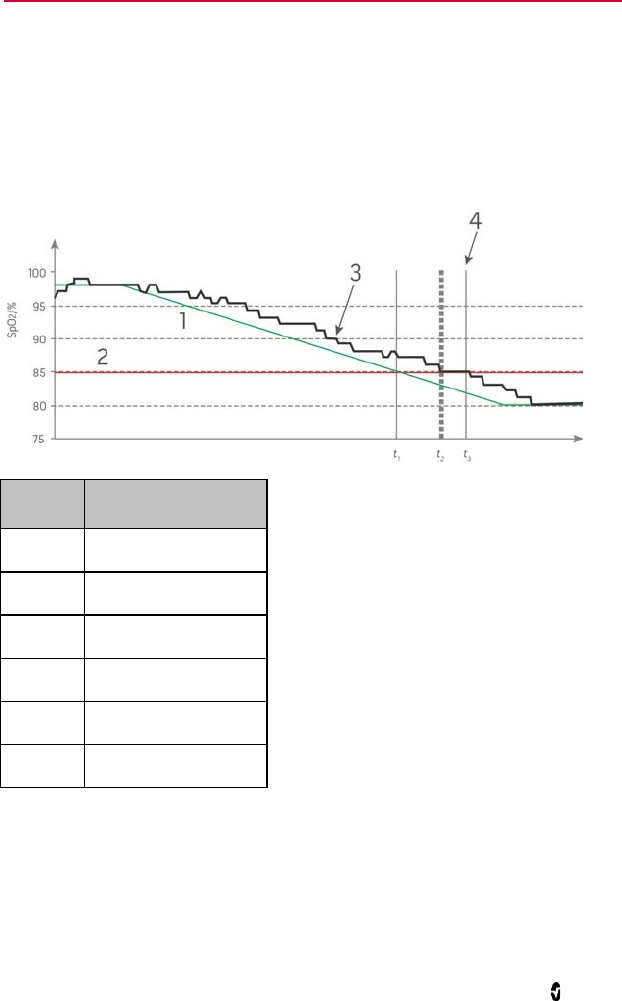
www.masimo.com 87 Masimo
Appendix
Concepts of Alarm Response Delay
As with any pulse oximeter equipment, the audible and visual alarms are subject to alarm
response delay, which is composed of Alarm Condition Delay and Alarm Signal Generation
Delay. Alarm Condition Delay is the time from the occurrence of the triggering event to when
the alarm system determines the alarm condition exists. While Alarm Signal Generation
Delay is the time from the onset of an alarm condition to the generation of its alarm signal.
The graphic below is a simplified illustration of the concept of alarm response delay and does
not reflect actual lengths of delays.
Reference Definition
1 SaO2
2 Alarm Limit
3 Displayed SpO2
4 Alarm Signal Generation
SpO2 Saturation
t Time

Radius-7 Appendix
www.masimo.com 88 Masimo
The Alarm Condition Delay is graphically represented as t2 – t1 in the figure above to show the
delay due to processing and averaging.
The Alarm Signal Generation Delay is graphically represented as t3 – t2 in the figure above to
show the delay due to alarm system strategy and communication time.
The overall alarm system delay time is graphically represented as t3 – t1.
For more information about alarm response delay, refer to ISO 80601-2-61.

www.masimo.com 89 Masimo
Index
A
About Alarms • 59
About the Main Screen • 42
About this Manual • 7
Accuracy • 69
Acoustic Sensor • 26
Acquisition System • 26
Adaptive Threshold Alarm (ATA) • 29, 44,
45
Alarm Limit Test • 83
Alarm Management • 60
Alarm Priorities • 59
Alarms • 72
Appendix • 87
B
Battery Charging Adapter • 34
Battery Operation and Maintenance • 36,
82, 83
Battery Test • 83
C
Chapter 1- Technology Overview • 19
Chapter 2- System Components • 31, 37
Chapter 3- Setup • 35, 82
Chapter 4- Operation • 41
Chapter 5- Alarms and Messages • 59
Chapter 6- Troubleshooting • 65
Chapter 7- Specifications • 69
Chapter 8 - Service and Maintenance •
35, 81
Charging the Radius-7 Battery Module •
34, 35, 36, 39, 82
Citations • 26, 80
Cleaning • 39, 81, 83, 84
Concepts of Alarm Response Delay • 87
Configuring Parameters • 43
Configuring Sensitivity Modes • 43
Connecting Radius-7 to Root via
Bluetooth • 36, 43, 67, 83
Contacting Masimo • 61, 66, 84
D
Display Indicators • 73
E
Electrical • 71
EMC Compliance • 73
Environmental • 71
Exclusions • 85
F
FastSat® (FST®) • 29
Functional Oxygen Saturation (SpO2) •
20
G
General Description for
Carboxyhemoglobin (SpCO) • 24
General Description for Methemoglobin
(SpMet) • 24
General Description for Oxygen
Saturation (SpO2) • 20
General Description for Perfusion Index
(PI) • 21
General Description for Pleth Variability
Index (PVI) • 21
General Description for Pulse Rate (PR) •
21
General Description for SpOC • 24
General Description for Total
Hemoglobin (SpHb) • 23
General System Description • 31
Guidance and Manufacturer's
Declaration- Electromagnetic
Emissions • 75

Radius-7 Index
www.masimo.com 90 Masimo
Guidance and Manufacturer's
Declaration- Electromagnetic
Immunity • 75
I
In Vivo Adjustment™ • 27, 44, 45, 49, 51,
52
Indications for Use • 9
M
Masimo rainbow SET Parallel Engines •
19
Masimo SET DST • 20
Measurement Range • 69
Messages • 61
N
Navigating Radius-7 Settings on Root •
43
Navigating the Main Menu • 36, 42, 66
O
Offset Value • 27
P
Patient • 25
Physical Characteristics • 72
PI Settings • 47
PR Settings • 46
Preparation for Use • 35
Product Description • 9
Product Description, Features and
Indications for Use • 9
PVI Settings • 48
R
Radio Compliance • 74
Radius-7 Armband • 34
Radius-7 Battery Module • 33
Radius-7 Instrument Module • 31
rainbow Acoustic Monitoring
Architecture • 25
rainbow Acoustic Monitoring™ (RAM™) •
25, 54
rainbow Pulse CO-Oximetry Technology •
22
Recommended Separation Distances • 77
Removing Radius-7 from Patient • 39
Repair Policy • 83
Resolution • 70
Respiration Rate Settings • 53
Restrictions • 85
Return Procedure • 83, 84
RRa Settings • 54
RRp Settings • 56
S
Safety Checks • 82
Safety Information, Warnings and
Cautions • 11, 59
Safety Standards Compliance • 73
Sales & End-User License Agreement •
85
Securing Radius-7 to Patient • 34, 37
Sensitivity Modes • 30, 43, 65
Signal Extraction Technology® (SET®) •
19
Signal IQ® (SIQ) • 28, 63
Signal Processing • 26
SpCO Settings • 51
SpCO, SpMet, and SpHb Measurements
During Patient Motion • 24
Speaker, Display and Touchpad Function
Test • 83
SpHb Settings • 49
SpMet Settings • 52
SpO2 Settings • 45
SpOC Settings • 53

Radius-7 Index
www.masimo.com 91 Masimo
Successful Monitoring for SpO2, PR and
PI • 20
Symbols • 78
T
Troubleshooting Measurements • 65
Troubleshooting Radius-7 • 66
U
Unpacking and Inspection • 35
Using the Touchpad • 41, 83
W
Warranty • 84

www.masimo.com
37292/LAB-8303B 0814