Masimo RDS7 RDS7 User Manual Root
Masimo Corporation RDS7 Root
UserManual.wiki
>
Masimo
>
RDS7 User Manual
User Manual
Navigation menu
Upload a User Manual
Namespaces
Wiki Guide
HTML
PDF
Info
Views
User Manual
Discussion / Help
Navigation
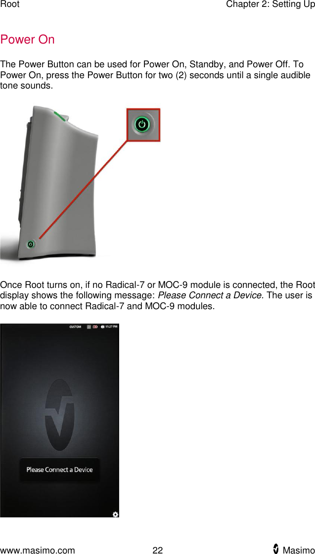
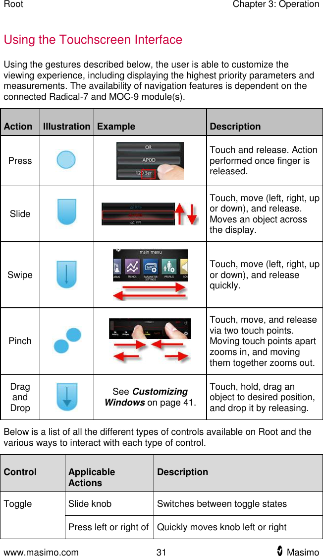
![www.masimo.com 21 Masimo Chapter 2: Setting Up Unpacking and Inspection To unpack and inspect Root 1. Remove Root from the shipping carton and examine it for signs of shipping damage or exposed electronics. 2. Check all materials against the packing list. Save all packing materials, invoice and bill of lading. These may be required to process a claim with the carrier. If anything is missing or damaged, contact Masimo's Technical Service Department. See Return Procedure on page 91. Guidelines for Setting Up Root has a built-in bracket interface that allows it to be mounted on a pole or roll stand. When setting up Root, follow these guidelines: Place on a stable, hard, flat and dry surface near the patient. Maintain a minimum of three (3) centimeters (one [1] inch) of free space around Root. Ensure that the back panel Speaker is not covered to avoid a muffled alarm sound. Charge Root's battery fully before use. See Initial Battery Charging on page 23. Root should not be operated outside the environmental conditions listed in the specifications section. See Environmental on page 79.](https://usermanual.wiki/Masimo/RDS7/User-Guide-2245893-Page-23.png)