Matrix Design Group 10000615 Matrix Intellizone MS3-IZ Locator User Manual Revised
Matrix Design Group, LLC Matrix Intellizone MS3-IZ Locator Revised
User Manual Revised

10002008 rev 0 Matrix Design Group, LLC | 3299 Tower Drive Newburgh, IN 47630, USA | 812.490.1525 | www.matrixteam.com
Copyright © 2013 Matrix. All rights reserved. Do not distribute without prior consent.
Engineering Safety • Advancing Automation
Matrix IntelliZone™
Proximity Detection System
Basic Information • 3rd Party

Engineering Safety • Advancing Automation
2
10002008 rev 0
Matrix Design Group, LLC | 3299 Tower Drive Newburgh, IN 47630, USA | 812.490.1525 | www.matrixteam.com
Copyright © 2013 Matrix. All rights reserved. Do not distribute without prior consent.
DO NOT DISTRIBUTE
IntelliZone™ System Index
System Warnings & Disclaimers (Page 3)
System Warnings & Disclaimers, System Warning Labels
System Introduction (Pages 4-6)
Objective, Overview, Expanding Zones, Directional Zones, Articulating Machinery, “Green” Zone
System Components (Pages 7-10)
Overview, Driver, Locator, Controller, Software Key, Interconnect Board, XP Boxes, Antenna Mounts
Basic Information
Driver (Page 12-14)
Overview, Splitter Layout, Driver Installation
Controller (Pages 15)
Overview, LED Statuses
System Information (Pages 16-18)
Available System Drawings, Fasteners, System Installation Guidelines
System Troubleshooting (Pages 19-22)
Driver LEDs, Locator LEDs, Audible Alarm, Locator OLED Screen, Troubleshooting Tips, System Diagnostic Codes
Maintenance Guide
Operating Guidelines (Page 24)
System Warnings, Precautions, System Overview
Driver and Locators (Page25-27)
Driver Overview, Locator Overview, LED Statuses
Emergency Stop Override (Pages 28-29)
DC, C2C, JNA
User Guide
Engineering Safety • Advancing Automation
3
10002008 rev 0
Matrix Design Group, LLC | 3299 Tower Drive Newburgh, IN 47630, USA | 812.490.1525 | www.matrixteam.com
Copyright © 2013 Matrix. All rights reserved. Do not distribute without prior consent.
DO NOT DISTRIBUTE
System Warnings & Disclaimers
It is important that all users / personnel that may come into contact with the IntelliZone™ Proximity Detection
System understand it’s purpose. It is NOT a safety system. It is a training aid developed to teach users safe
operating habits. User / Operator assumes full responsibility for control of the machine upon which the system
is installed. User / Operator assumes full liability for the maintenance and operation of the IntelliZone™
Proximity Detection System.
System Warnings & Disclaimers
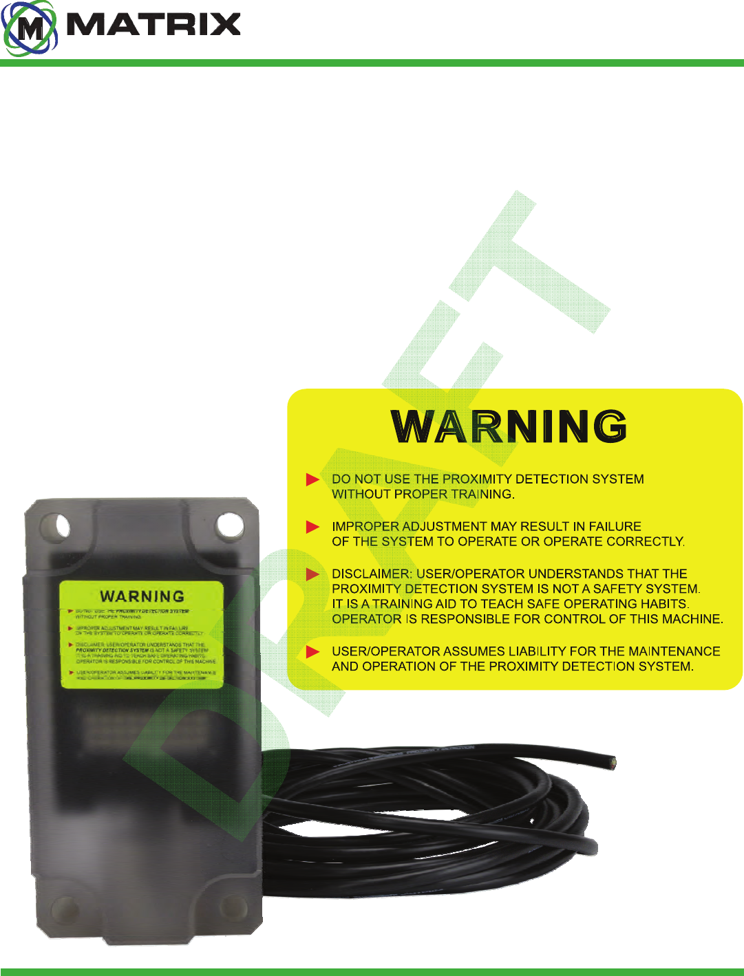
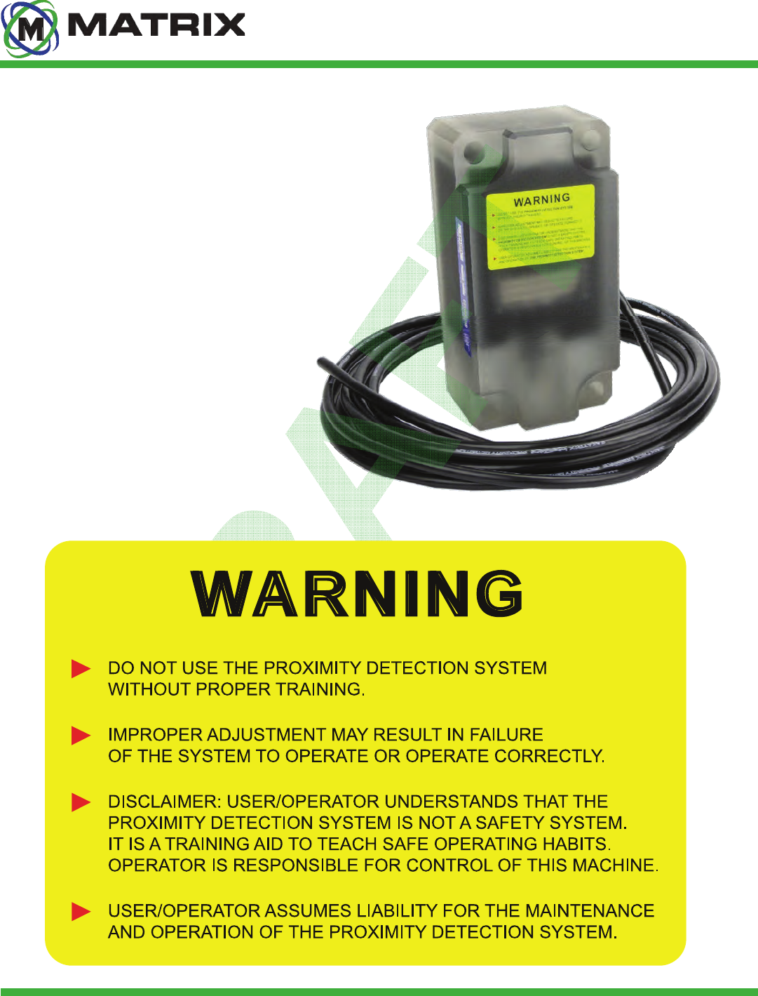
The Matrix IntelliZone™ System includes several highly visible WARNING labels located on the front of the
machine-mounted Drivers, and the user-carried Locators. All users / personnel that may come into contact
with an IntelliZone™ Proximity Detection System equipped machine should familiarize themselves with all
WARNINGS associated with the system. Additional WARNING labels for the IntelliZone™ System are
available free-of-charge as requested.
System Warning Label
Engineering Safety • Advancing Automation
4
10002008 rev 0
Matrix Design Group, LLC | 3299 Tower Drive Newburgh, IN 47630, USA | 812.490.1525 | www.matrixteam.com
Copyright © 2013 Matrix. All rights reserved. Do not distribute without prior consent.
DO NOT DISTRIBUTE
The intent of IntelliZone™ Proximity Detection is to provide a practical, mine-duty system that will
automatically warn personnel when they are entering a potentially hazardous area around a machine. The
system must be able to disable some or all machine functions if a particular zone is breached.
Objective
The Matrix IntelliZone™ Proximity Detection System assists with training personnel to stay clear of dangerous
zones present around potentially hazardous equipment. The System is designed for use on mobile equipment
such as continuous miners, mobile haulage, and other light and heavy vehicles. The System is typically
configured for two operational awareness zones: a “shutdown zone” (red) can be defined closest to the
equipment and a “warning zone” (yellow) can be defined to extend a moderate distance from the equipment.
When an IntelliZone™ Locator is detected within the red zone, the System will prompt the equipment to
immediately shutdown some or all of its functions. When an IntelliZone™ Locator is detected within the
yellow zone, the System will prompt the equipment to reduce its speed or influence other changes in
operation. If a Locator is detected within either zone, the System will initiate highly-visible flashing lights and
an audible alarm on the Locator and Drivers to warn personnel of potential hazards.
Additional IntelliZone™ awareness zones can be
configured as needed and are customizable to specific
equipment and applications.
System Overview
IntelliZone™ System Introduction
Engineering Safety • Advancing Automation
5
10002008 rev 0
Matrix Design Group, LLC | 3299 Tower Drive Newburgh, IN 47630, USA | 812.490.1525 | www.matrixteam.com
Copyright © 2013 Matrix. All rights reserved. Do not distribute without prior consent.
DO NOT DISTRIBUTE
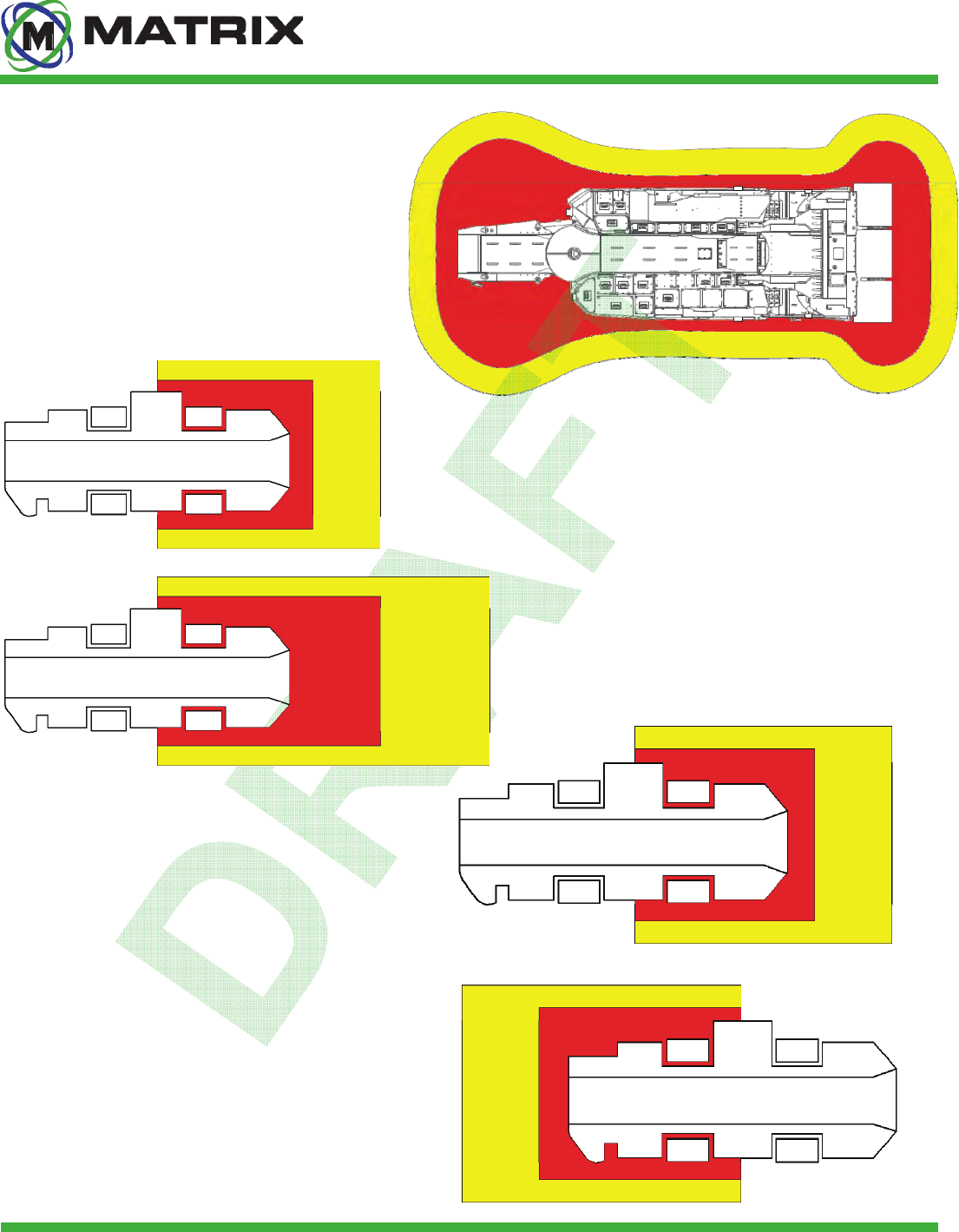
Standard Miner Configuration
IntelliZone™ System Introduction
Consists of a shutdown zone (red) and
warning zone (yellow), as well as operator
zone (green) while cutting. These zones are
configurable through software.
On mobile equipment, zones can be
configured to expand as the machine
accelerates. Oversized zones are no longer
required on faster moving equipment.
Expanding Mobile Equipment Zones
On mobile equipment, zones can be
configured to react to the equipment’s
direction. This prevents the machine from
being shut down by personnel walking behind
it.
Directional Mobile Equipment Zones
Engineering Safety • Advancing Automation
6
10002008 rev 0
Matrix Design Group, LLC | 3299 Tower Drive Newburgh, IN 47630, USA | 812.490.1525 | www.matrixteam.com
Copyright © 2013 Matrix. All rights reserved. Do not distribute without prior consent.
DO NOT DISTRIBUTE
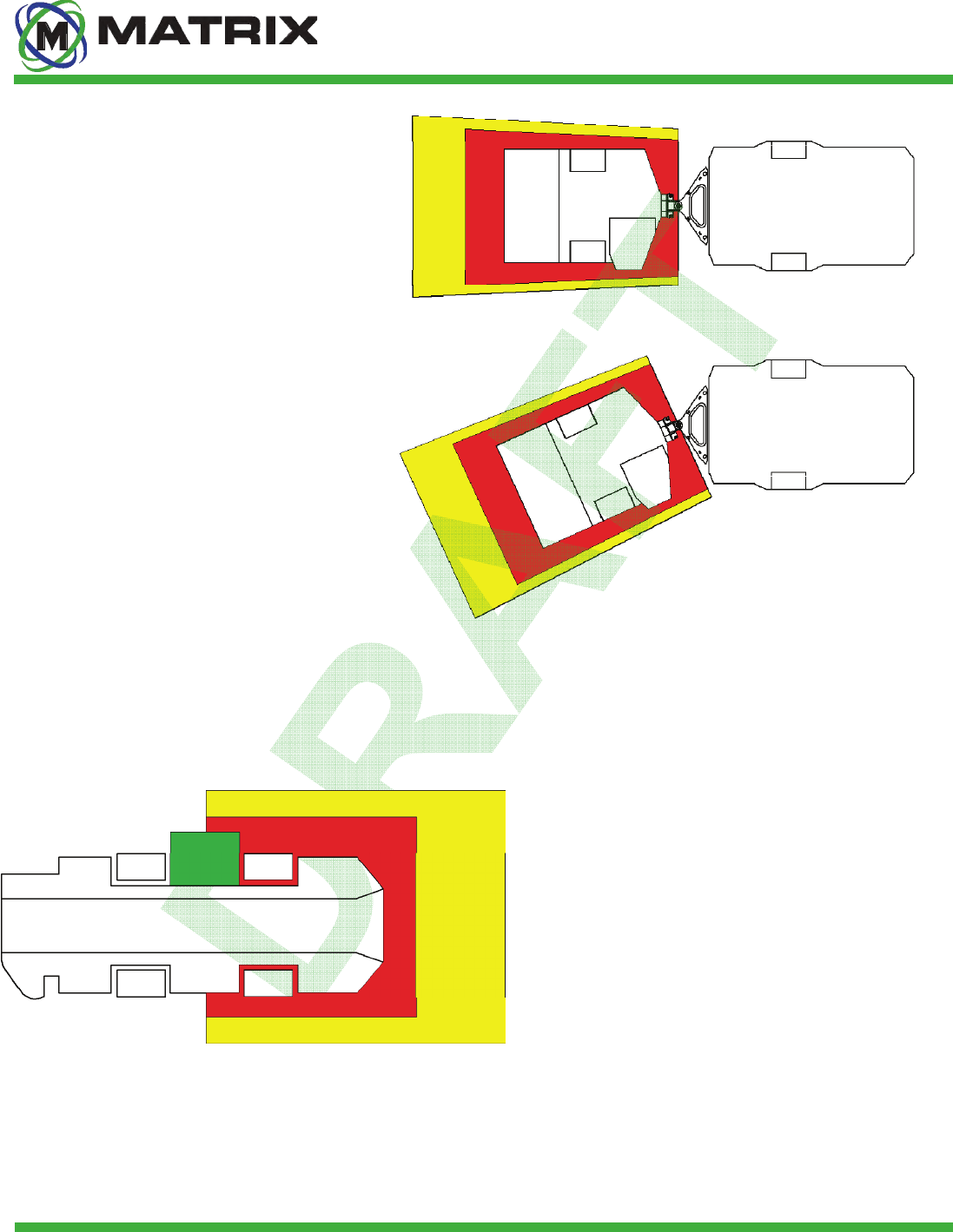
IntelliZone™ System Introduction
On articulating machinery, the zones can
configured to react to the pivoting of the
machine. This enables the zones to remain
consistent even when the machine is
articulated.
Articulating Machinery
Operator zones can be configured using the
Intellizone GUI. These operator zones are
critical in that it allows the associated Locator
to be in the area without shutting down the
machinery.
Operator (Green) Zone
Engineering Safety • Advancing Automation
7
10002008 rev 0
Matrix Design Group, LLC | 3299 Tower Drive New-
burgh, IN 47630, USA | 812.490.1525 |
DO NOT DISTRIBUTE
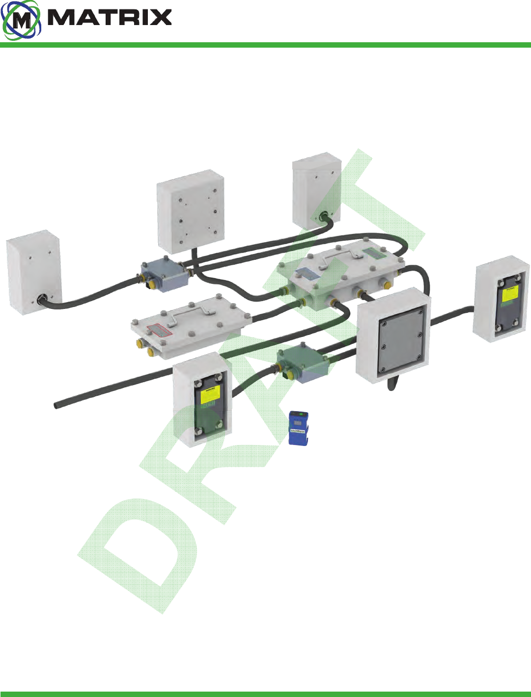
System Components
❶
❷
❹
❺
❻
❼
❽
❸
❶MX3-IZ Driver (4 shown)
❷ MX3-IZ Locator
❸ MX3-IZ Splitter Box (2 shown)
❹ M3-1000 Guarding (2 shown)
❺ MX3-IZ Antenna Mounting Kit, Retrofit (2 shown)
❻ MX3-IZ Guarding (4 shown)
❼ MX3-IZ Power Supply Box
❽ MX3-IZ Proximity Controller Box
IntelliZone™ System Introduction
The IntelliZone™ System is approved for use in potentially hazardous MSHA-regulated environments. Below
is a typical layout for a system on a machine. System components may vary in quantity and location
depending on the machine upon which it is mounted.
Engineering Safety • Advancing Automation
8
10002008 rev 0
Matrix Design Group, LLC | 3299 Tower Drive Newburgh, IN 47630, USA | 812.490.1525 | www.matrixteam.com
Copyright © 2013 Matrix. All rights reserved. Do not distribute without prior consent.
DO NOT DISTRIBUTE
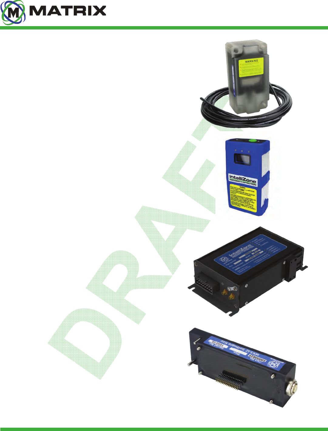
MX3-IZ Driver
IntelliZone™ System Introduction
The MSHA-approved Driver allows for tracking of multiple
Locators. The Driver is machined from rugged polycarbonate and
incorporates multi-color LEDs used for diagnostics and zone
identifications.
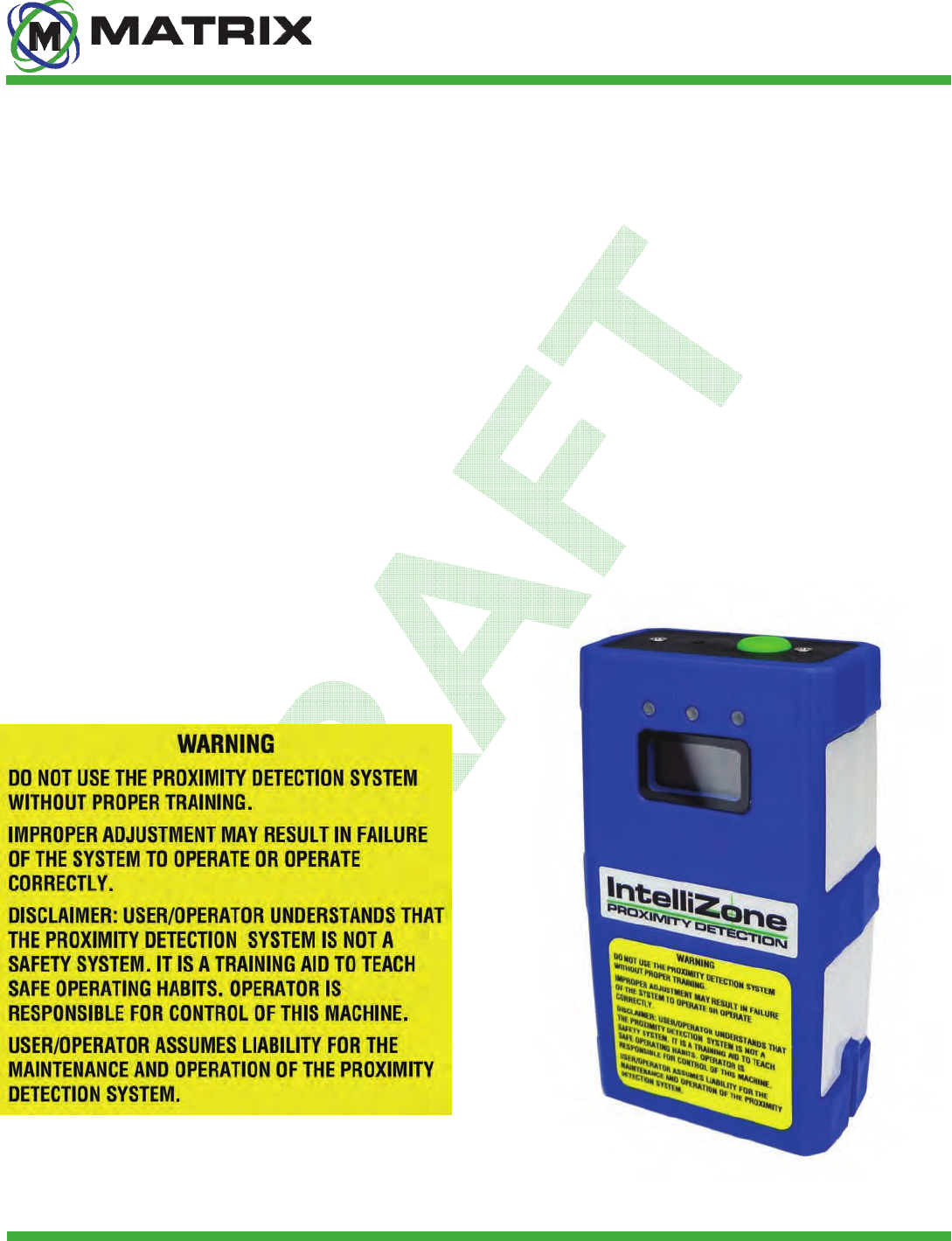
MX3-IZ Locator
The MSHA-approved Locator is the device the operator wears
and that is tracked around the machine. The Locator also has a
built-in audible and visible warning. The operator uses this device
to associate/dissociate. It can be worn in a pouch or using a belt
clip.
MX3-IZ Controller
The Controller is the central processor for the IntelliZone™
System. It communicates to the mobile equipment and
Locators and provides power to 4 machine-mounted Drivers.
Personnel can connect to the Controller wirelessly (w/ adaptor)
or with an Ethernet cable to adjust settings and view system
diagnostics. This device IS NOT intrinsically safe and
MUST be inside an explosion-proof enclosure when used in
MSHA-regulated environments.
MX3-IZ Software Key
The Software Key must be installed on the Controller for the
system to function. It can be moved to a new Controller in
event of a failure. This stores the machine configuration and
provides an Industrial Ethernet connection. The Software
Key IS NOT intrinsically safe and MUST be inside an explosion-
proof enclosure when used in MSHA-regulated environments.
Engineering Safety • Advancing Automation
9
10002008 rev 0
Matrix Design Group, LLC | 3299 Tower Drive Newburgh, IN 47630, USA | 812.490.1525 | www.matrixteam.com
Copyright © 2013 Matrix. All rights reserved. Do not distribute without prior consent.
DO NOT DISTRIBUTE
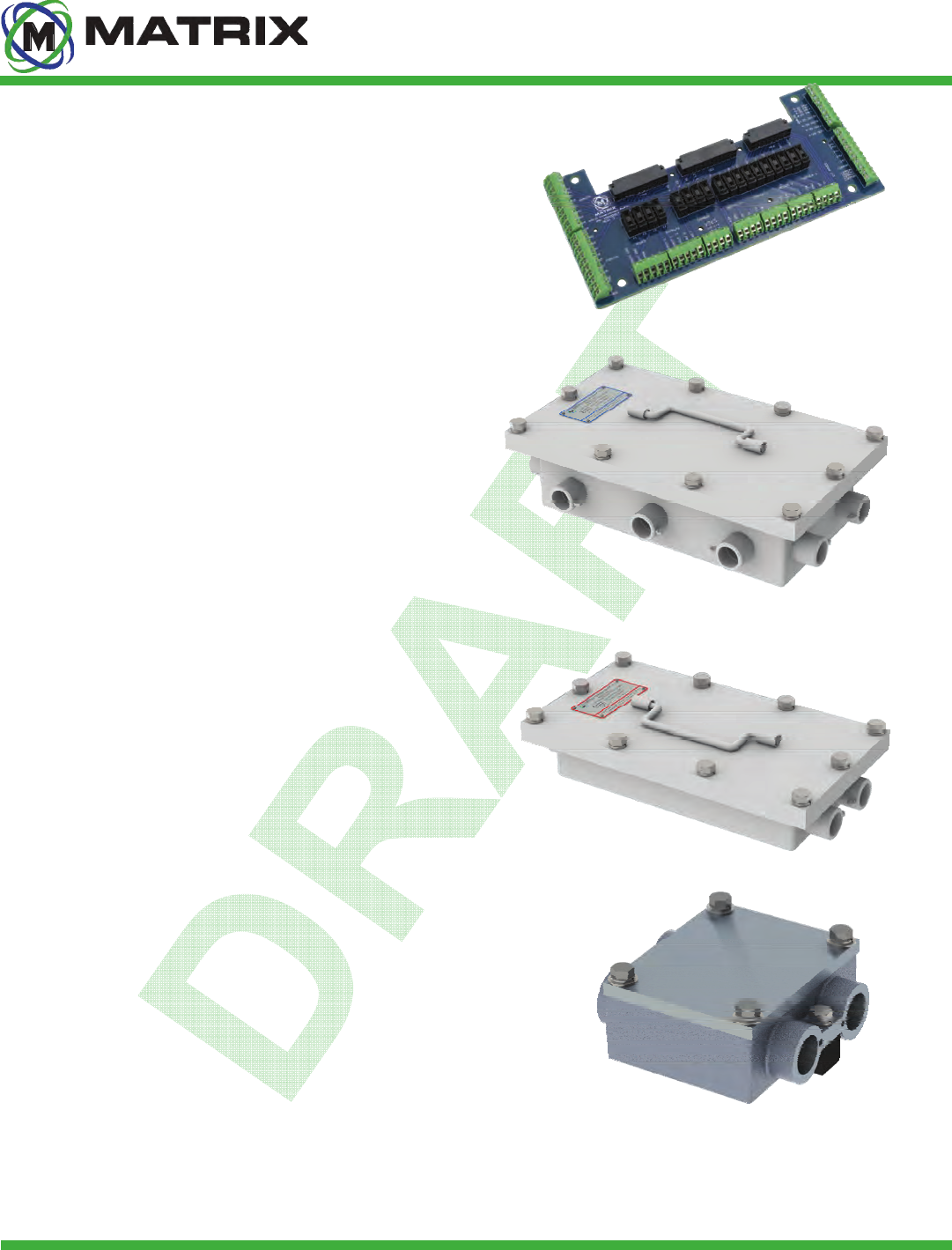
MX3-IZ Interconnect Board
IntelliZone™ System Introduction
The Interconnect Board is the hub for all relays, inputs,
outputs, power, etc. that interfaces to the Controller. This
board mounts below the Controller and is designed for easy
access to all wiring terminals. The Interconnect Board IS NOT
intrinsically safe and MUST be inside an explosion-proof
enclosure when used in MSHA-regulated environments.
Controller XP Box
This MSHA-approved enclosure houses the Controller,
Software Key, and Interconnect Board. It features 7 ports
that use 1.125-12 packing gland assemblies to ensure
the enclosure remains explosion proof.
Power Supply XP Box
This MSHA-approved enclosure houses the Intellizone
Power Supply. It features 4 ports that use 1.125-12
packing gland assemblies to ensure the enclosure
remains explosion proof.
Splitter XP Box
This MSHA-approved enclosure is used to minimize the number
of Controller XP Box ports needed. Typically 2 Splitter XP Boxes
are used per system; one being placed on each side of the
machinery. It features 4 ports that use 1.125-12 packing gland
assemblies to ensure the enclosure remains explosion proof.
Engineering Safety • Advancing Automation
10
10002008 rev 0
Matrix Design Group, LLC | 3299 Tower Drive Newburgh, IN 47630, USA | 812.490.1525 | www.matrixteam.com
Copyright © 2013 Matrix. All rights reserved. Do not distribute without prior consent.
DO NOT DISTRIBUTE
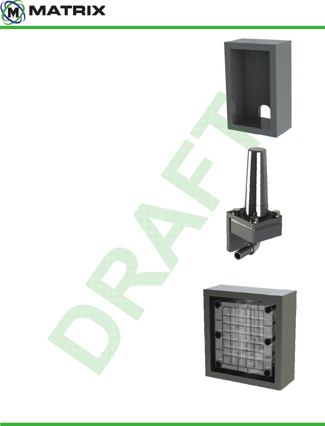
Driver Guarding
IntelliZone™ System Introduction
The guarding around Driver is MSHA-approved and therefore
must be manufactured to specific dimensions. The outer guarding
must be at minimum 1/4” thick. The backing must be at minimum
5/8’” thick. The gap between the guarding and Driver can not
exceed 1/2”. For more information see drawing # 10000099.
Whip Antenna Kit
This kit includes a 2.45Ghz Whip antenna, mounting hardware,
polycarbonate cover, pipe nipple, and elbow for a large range of
custom mounting configurations. This antenna kit is a proven
design for haulage equipment such as shuttle cars and battery
haulers. It requires much less room than the retrofit Antenna Kit.
Retrofit Antenna Kit
This kit includes a 2.45Ghz Whip antenna, mounting hardware,
and a polycarbonate cover. It was designed to mount directly into
existing guarding on equipment fitted with previous generation
proximity detection systems.
Engineering Safety • Advancing Automation
12
10002008 rev 0
Matrix Design Group, LLC | 3299 Tower Drive Newburgh, IN 47630, USA | 812.490.1525 | www.matrixteam.com
Copyright © 2013 Matrix. All rights reserved. Do not distribute without prior consent.
DO NOT DISTRIBUTE
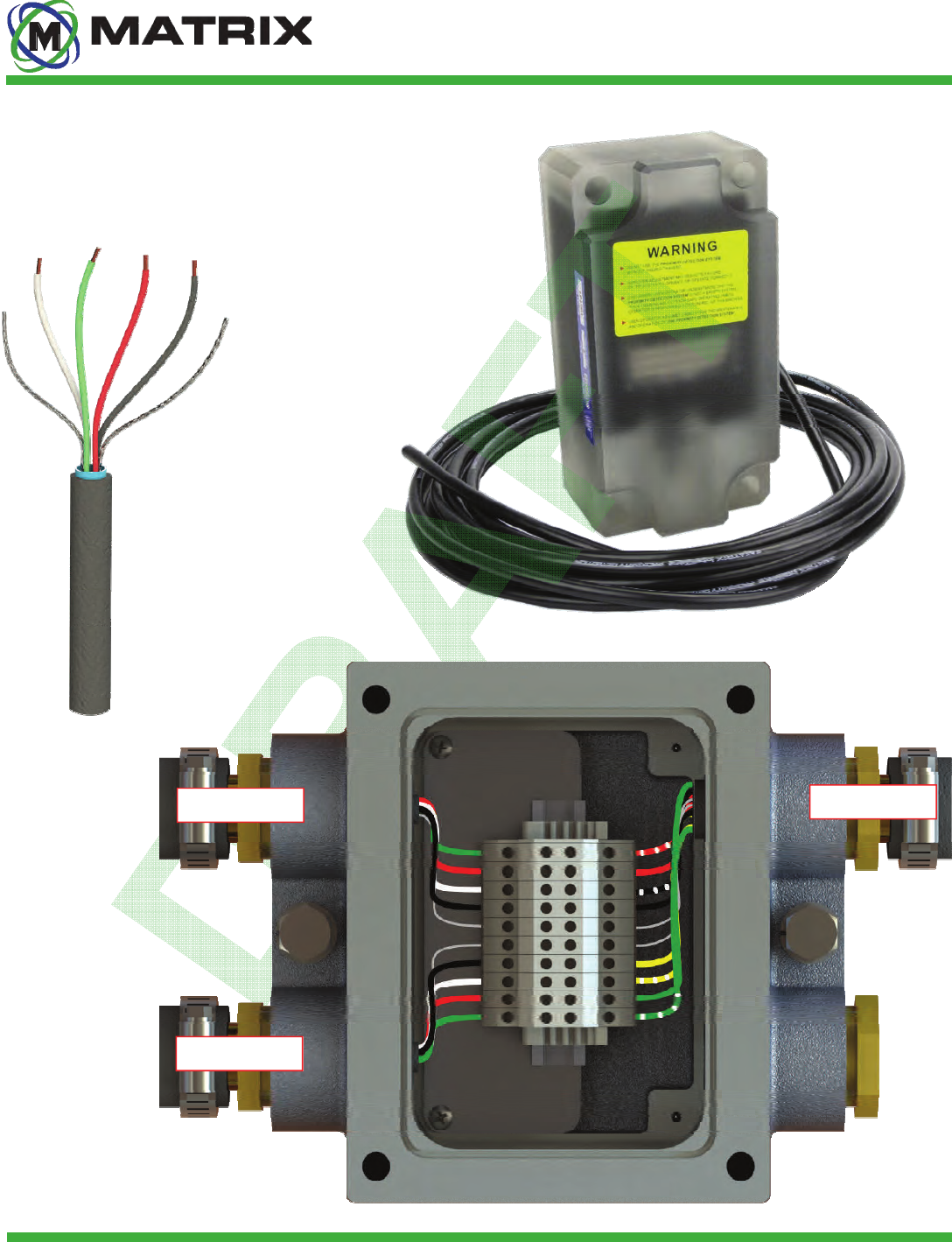
MX3-IZ Driver Installation
Maintenance Guide
10000050
Driver Cable
❶ Shield
❷ White (Data +)
❸Green (Ground)
❹ Red (+72VDC)
❺ Black (Data -)
❶
❷
❶
❸ ❹ ❺
Splitter Cable
Front Driver
Back Driver
Engineering Safety • Advancing Automation
13
10002008 rev 0
Matrix Design Group, LLC | 3299 Tower Drive Newburgh, IN 47630, USA | 812.490.1525 | www.matrixteam.com
Copyright © 2013 Matrix. All rights reserved. Do not distribute without prior consent.
DO NOT DISTRIBUTE IntelliZone™ System Kits
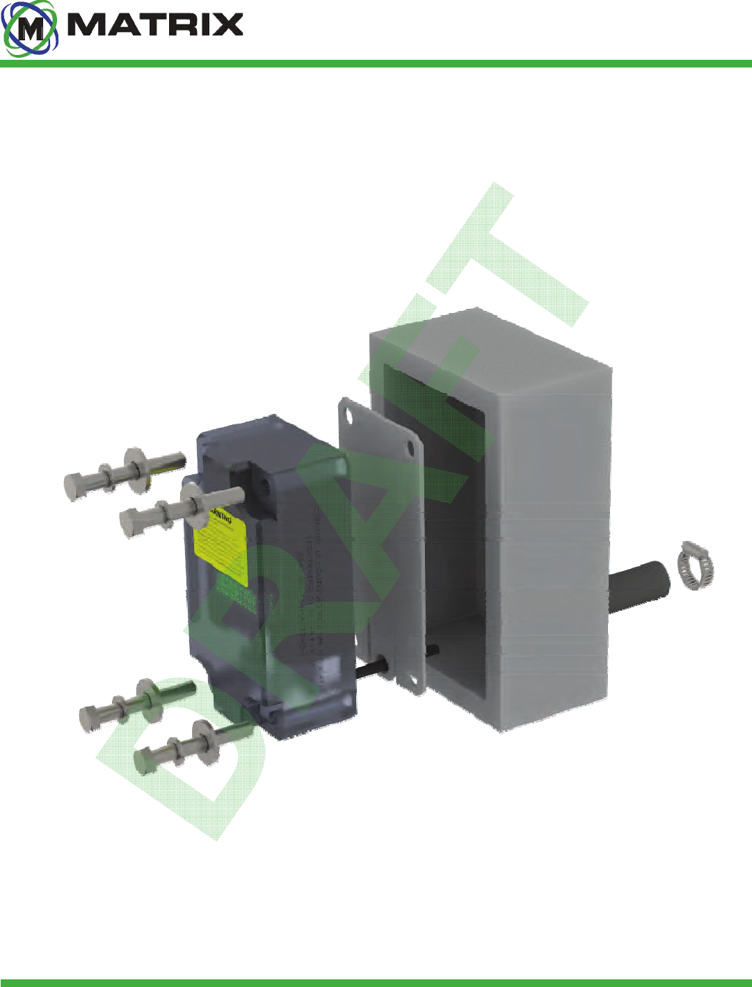
MX3-IZ Driver Standard Installation
The MX3-IZ Guarding that protects the Drivers is specifically designed for the new smaller MX3-IZ Drivers
unlike previous Matrix Proximity Systems with larger guarding. The Driver cable must be inside conduit for its
entire run and must be connected to either a MX3-IZ Conduit Mounting Plate or a conduit mounting nipple that
is attached to the back or top of the guarding. The driver is mounted using M12 x 85mm Hex head bolts with
washers and lock washers.
❶
❷
❸
❹
❺
❻
❶ M12 Mounting Hardware
❷ MX3-IZ Driver
❸ MX3-IZ Conduit Mounting Plate
❹ MX3-IZ Guard
❺ 3/4” I.D. Rubber Hose Conduit
❻ S.S. Worm Gear Hose Clamp
Engineering Safety • Advancing Automation
14
10002008 rev 0
Matrix Design Group, LLC | 3299 Tower Drive Newburgh, IN 47630, USA | 812.490.1525 | www.matrixteam.com
Copyright © 2013 Matrix. All rights reserved. Do not distribute without prior consent.
DO NOT DISTRIBUTE IntelliZone™ System Kits
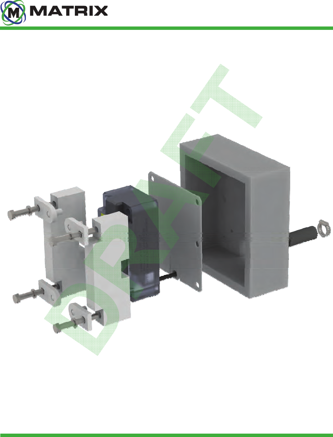
MX3-IZ Driver Retrofit Installation
The MX3-IZ Driver Adapter Kit is specifically designed for mounting the MX3-IZ Driver in the larger guarding
that is standard on the older M3K-1000 Matrix Proximity System. The Driver cable must be inside conduit for
its entire run and must be connected to either a MX3-IZ Conduit Mounting Plate or a conduit mounting nipple
that is attached to the back or top of the guarding. The driver is mounted using M12 x 90mm Hex head bolts
with lock washers.
❶
❷
❸
❹
❺
❻
❶ M12 Mounting Hardware
❷ MX3-IZ Driver Adapter Kit
❸ MX3-IZ Driver
❹ MX3-IZ Conduit Mounting Plate, Retrofit
❺ M3-1000 Guard
❻ 3/4” I.D. Rubber Hose Conduit
❼ S.S. Worm Gear Hose Clamp
❼
Engineering Safety • Advancing Automation
15
10002008 rev 0
Matrix Design Group, LLC | 3299 Tower Drive Newburgh, IN 47630, USA | 812.490.1525 | www.matrixteam.com
Copyright © 2013 Matrix. All rights reserved. Do not distribute without prior consent.
DO NOT DISTRIBUTE Maintenance Guide
10000050
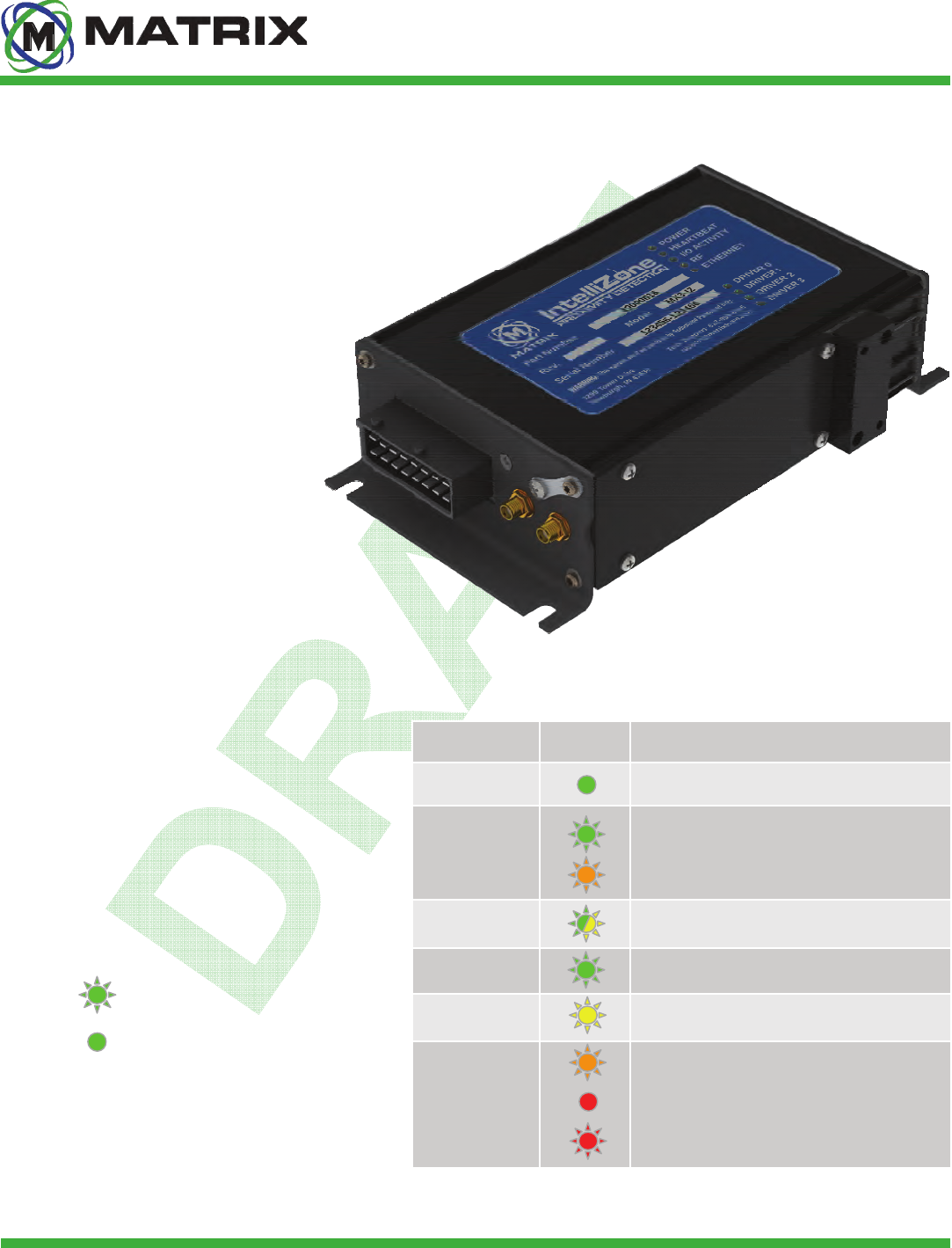
The Controller is the central processor for the
IntelliZone™ System. It communicates to
the mobile equipment and Locators
and provides power to 4 machine-
mounted Drivers. Personnel can
connect to the Controller wirelessly (w/
adaptor) or with an Ethernet cable to
adjust settings and view system
diagnostics. This device IS NOT
intrinsically safe and MUST be
inside an explosion-proof enclosure
when used in MSHA-regulated
environments.
MX3-IZ Controller
Overview
The Controller features (9) LEDs that
can provide the operator with basic
system diagnostics information. The
LEDs are located on the top surface
of the Controller, and can be in either
a blinking or continuously lit (solid).
LED States
Blinking
Solid
POWER CONTROLLER HAS POWER
HEARTBEAT
CONTROLLER SOFTWARE IS ACTIVE
INTERFACE & PROXIMITY ARE ACTIVE
I/O ACTIVITY I/O ACTIVITY (SD CARD OR SENSORS)
RF RF ACTIVITY
ETHERNET WIRED NETWORK ACTIVITY
DRIVER 0-3
NORMAL OPERATION
DRIVER DISABLED
POWER FAILURE
FUNCTION LED RESPONSE
Engineering Safety • Advancing Automation
16
10002008 rev 0
Matrix Design Group, LLC | 3299 Tower Drive Newburgh, IN 47630, USA | 812.490.1525 | www.matrixteam.com
Copyright © 2013 Matrix. All rights reserved. Do not distribute without prior consent.
DO NOT DISTRIBUTE Maintenance Guide
Available System Drawings
Drawing Product Category Description
10000058 Driver Installation Detail Shows proper installation of Driver w/ and w/o adapter kit
10001901 Charger Product Overview Provides generic Locator Charger dimensions and specs
10001691 Charging Rack Product Overview Provides generic Locator Charging Rack dimensions and specs
10001659 Power Supply Box Schematic Wiring Schematic for system power supply box
10001978 Controller Box Schematic Wiring Schematic for system Controller box
10001638 Controller Box Product Overview Provides generic Controller XP Box dimensions and specs
10001685 Controller Box Installation Detail Shows proper installation of Controller XP Box w/ use of weld blocks
10001639 Power Supply Box Product Overview Provides generic Power Supply Box dimensions and specs
10001950 Antenna Kit Installation Detail Shows proper installation of the Whip Antenna Mounting Kit
10001950 Retrofit Antenna Kit Installation Detail Shows proper installation of the Retrofit Antenna Mounting Kit
10000152 Overall System Product Overview Provides a generic overview of the entire system
10001288 Overall System Schematic Provides a generic overall system wiring schematic
10001974 C2C System Schematic Provides an overall system wiring schematic for a JOY C2C machine
10001975 JNA System Schematic Provides an overall system wiring schematic for a JOY JNA machine
10001976 DC System Schematic Provides and overall system wiring schematic for a JOY DC machine
10001977 BH-18 System Schematic Provides an overall system wiring schematic for a JOY BH-18 machine
10000112 Shuttle Car System Installation Detail Provides a generic system layout on a Standard Shuttle Car
10000127 Shuttle Car System Installation Detail Provides a generic layout of Driver Guarding on a Standard Shuttle Car
10000132 14CM15 R. System Installation Detail Provides a generic retrofit system layout on a JOY 14CM15 machine
10001603 14CM15 System Installation Detail Provides a generic system layout on a JOY 14CM15 machine
††† Multiple Drawing Numbers are available for product under the listed category. Please request drawings by “Product” column
name to receive a list of available drawings for the desired product.
Engineering Safety • Advancing Automation
17
10002008 rev 0
Matrix Design Group, LLC | 3299 Tower Drive Newburgh, IN 47630, USA | 812.490.1525 | www.matrixteam.com
Copyright © 2013 Matrix. All rights reserved. Do not distribute without prior consent.
DO NOT DISTRIBUTE Maintenance Guide
Fasteners
Fastener Quantity
MX3-IZ Driver
Hex Head M12-1.75x85 4
Washer M12 4
Washer Split Lock M12 4
MX3-IZ Driver Retrofit Kit
Hex Head M12-1.75x90 4
Washer Split Lock M12 4
MX3-IZ Controller XP Box
Hex Head 1/2-13x1.25 10
Washer Split 1/2 10
Nut Hex Jam 3/8-16 4
MX3-IZ Power Supply XP Box
Hex Head 1/2-13x1.25 10
Washer Split 1/2 10
Nut Hex 1/4-20 4
MX3-IZ Machine Mount Blocks
Hex Head 1/2-13x1.0 1
Washer Split 1/2 1

Engineering Safety • Advancing Automation
18
10002008 rev 0
Matrix Design Group, LLC | 3299 Tower Drive Newburgh, IN 47630, USA | 812.490.1525 | www.matrixteam.com
Copyright © 2013 Matrix. All rights reserved. Do not distribute without prior consent.
DO NOT DISTRIBUTE Maintenance Guide
Installation Requirements
Drivers can be mounted upside down, but must be vertical
Controller and Power Supply XP Enclosures must pass 0.004 feeler gauge inspection
Splitter XP Enclosures must pass 0.002 feeler gauge inspection
XP Gland Gap (Between Gland Plug and XP Box Steel Port) must measure between 1/8” MIN, 1/4” MAX
Glands must be secured with a lead tie or set screw
Open gland ports must be sealed using Steel Plug, and plug must be spot welded in place
Components on a common frame must be solidly frame grounded
The Intrinsically safe portion of the RF Barrier must be kept isolated from the non-Intrinsically safe wiring
Ensure that RF antennas are isolated from machine ground
Driver cables and 8-pair Matrix Cable must be installed with protective conduit and clamps
Antenna cables (LMR195-fr) do not require conduit but are highly recommended for protection
Though not required, ferrules or tinning the end of all wires inside the Controller XP Box and Splitter XP Box is
recommended
Engineering Safety • Advancing Automation
19
10002008 rev 0
Matrix Design Group, LLC | 3299 Tower Drive Newburgh, IN 47630, USA | 812.490.1525 | www.matrixteam.com
Copyright © 2013 Matrix. All rights reserved. Do not distribute without prior consent.
DO NOT DISTRIBUTE
Maintenance Guide
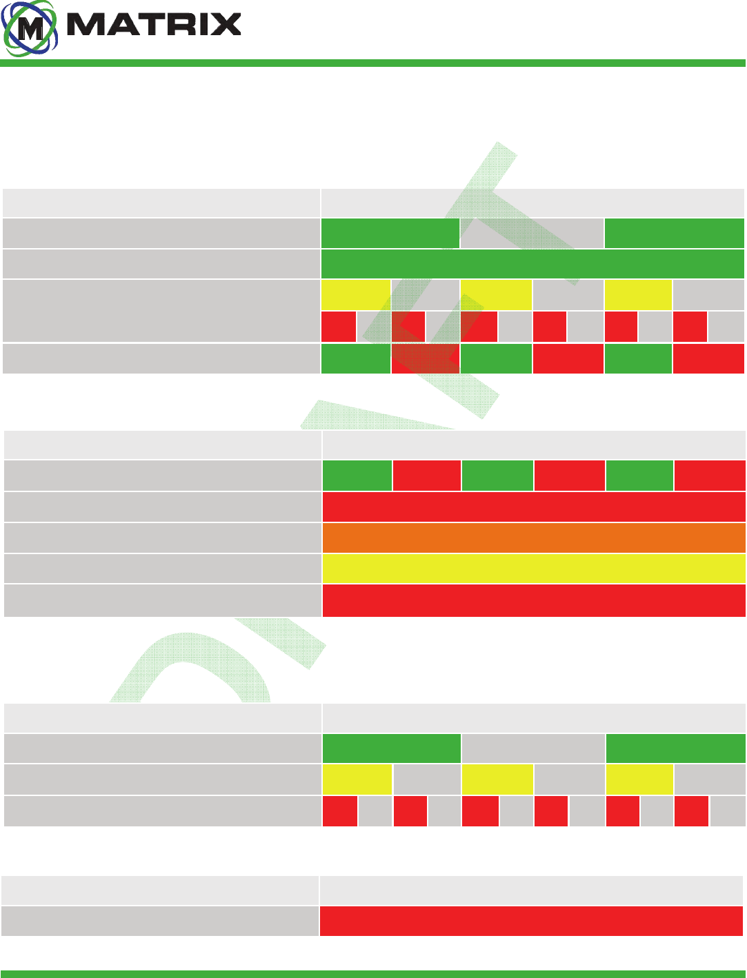
The Driver features an array of (27) LEDs that can provide the operator with basic system diagnostic
information. The LEDs are visible from the front of the Driver, and assume either a blinking or solid state.
Knowledge of Driver LED codes can help isolate system errors, should a problem arise. The error codes are
communicated to personnel by means of LED color and duration.
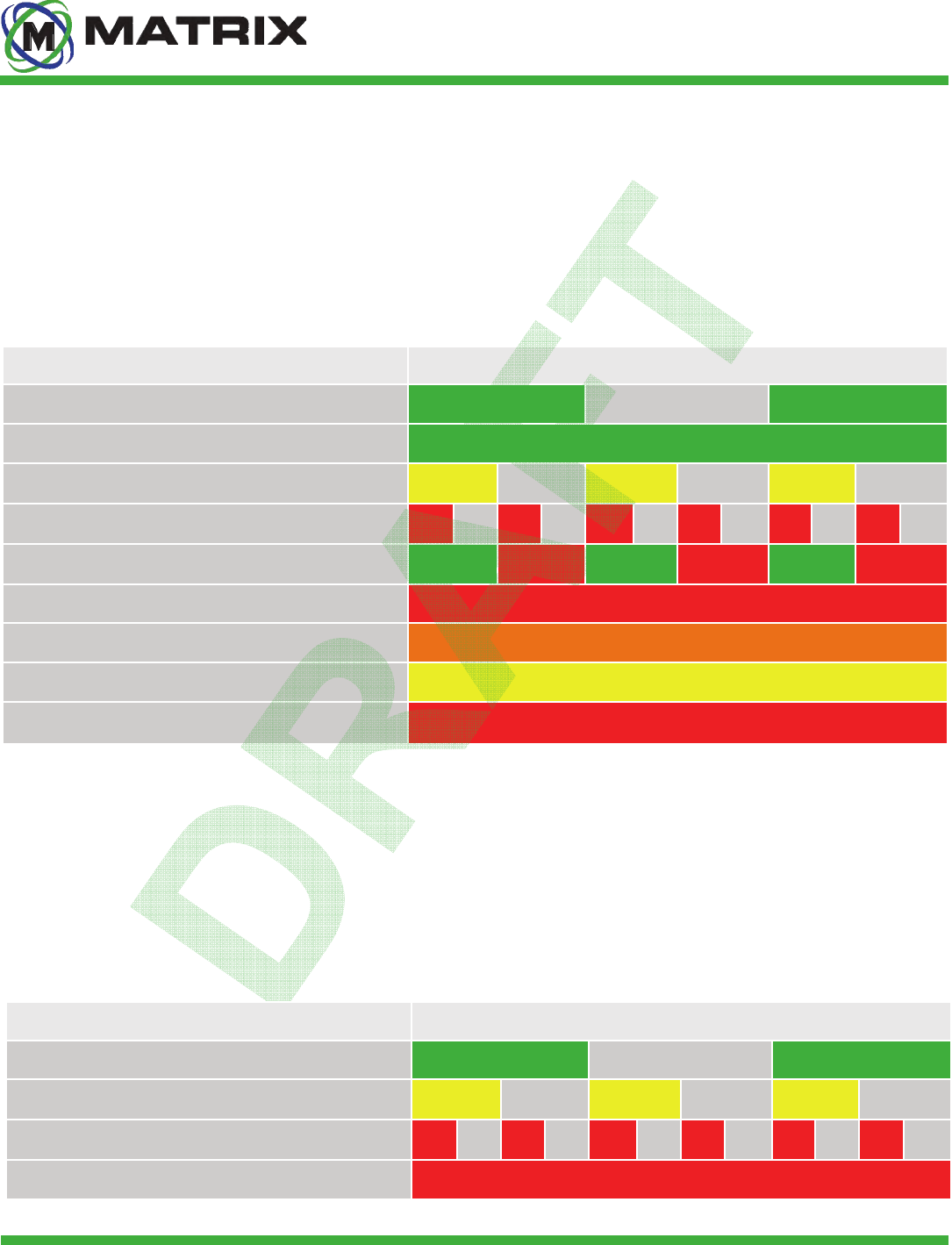
MX3-IZ Driver LED States
DEFINITION TIME DURATION (SECONDS)
System operational; no Locator associated as operator 1.0 1.0 1.0
System operational; Locator associated as operator Continuous
Warning Zone Breach ½ ½ ½ ½ ½ ½
Shutdown Zone Breach ¼ ¼ ¼ ¼ ¼ ¼ ¼ ¼ ¼ ¼ ¼ ¼
Proximity Protection System is bypassed ½ ½ ½ ½ ½ ½
System Error Continuous
MX3-IZ Locator Error Continuous
MX3-IZ Driver Error (Diagnostic Warning); single LED Continuous
MX3-IZ Driver Error (Diagnostic Error); single LED Continuous
The Locator features (3) LEDs that can provide the operator with basic system diagnostic information. The
LEDs are visible from the front of the Locator, and assume either a blinking or solid state. Knowledge of
Locator LED codes can help isolate system errors, should a problem arise. The error codes are
communicated to personnel by means of LED color and duration.
MX3-IZ Locator LED States
DEFINITION TIME DURATION (SECONDS)
System Operation Normal 1.0 1.0 1.0
Warning Zone Breach ½ ½ ½ ½ ½ ½
Shutdown Zone Breach ¼ ¼ ¼ ¼ ¼ ¼ ¼ ¼ ¼ ¼ ¼ ¼
System, Locator, or Driver Error Continuous
Engineering Safety • Advancing Automation
20
10002008 rev 0
Matrix Design Group, LLC | 3299 Tower Drive Newburgh, IN 47630, USA | 812.490.1525 | www.matrixteam.com
Copyright © 2013 Matrix. All rights reserved. Do not distribute without prior consent.
DO NOT DISTRIBUTE
Maintenance Guide
The Locator also features an audible alarm that can alert users and/or nearby personnel of a zone breach.
MX3-IZ Audible Alarm
DEFINITION TIME DURATION (SECONDS)
Warning Zone Breach ½ ½ ½ ½ ½ ½
Red Zone Breach ¼ ¼ ¼ ¼ ¼ ¼ ¼ ¼ ¼ ¼ ¼ ¼
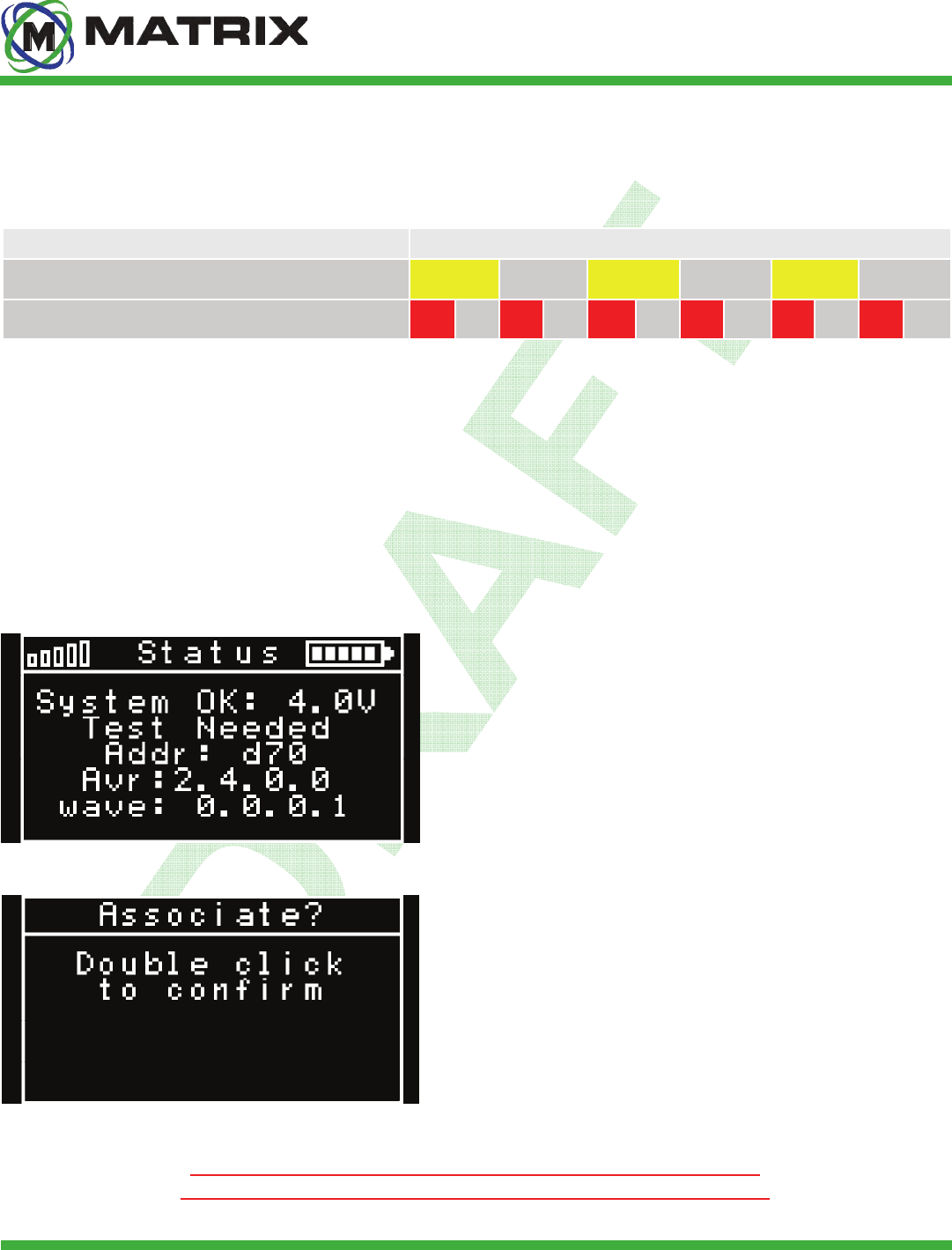
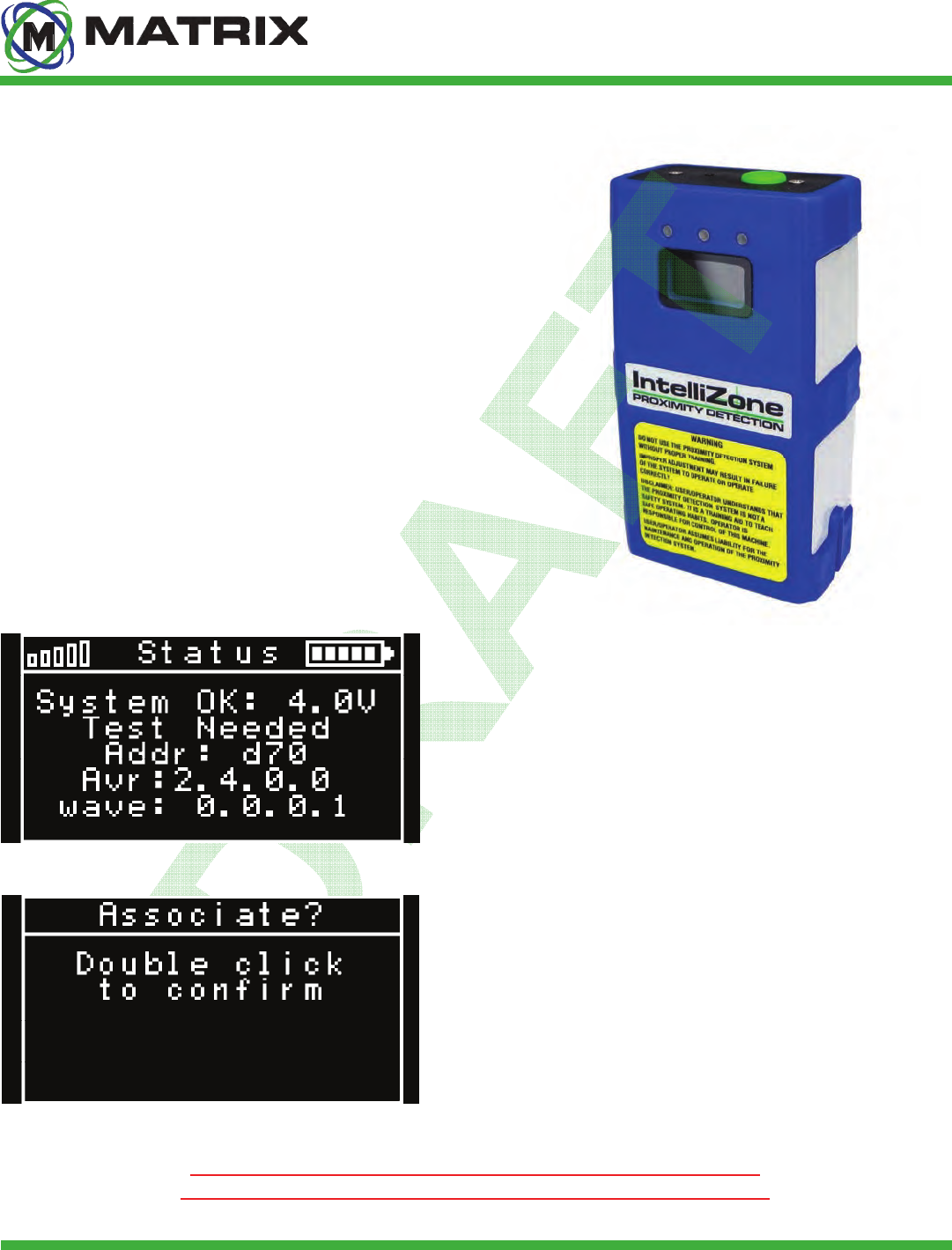
The user-interface screen on the front of the Locator provides personnel with important system diagnostics
information. It allows users to initiate key features of the IntelliZone™ System. It is important to understand
the information provided and how to properly interact with the Locator. User input is provided through the
push-button found atop the Locator and prompts on the OLED screen.
OLED Screen
STATUS SCREEN (PRESS + HOLD)
❶Signal Strength and Battery Level
❷System Status and Locator Operating Voltage
❸When displayed, test using MX3-IZ Locator Tester
❹Locator Identification
❺Development Information
❻Development Information
ASSOCIATE / DISSOCIATE (DOUBLE CLICK)
This allows users to associate / dissociate themselves as an
operator of a particular piece of machinery. In order to do so,
there must first be an Initiation Zone configured using the
IntelliZone™ System GUI (Graphical User Interface). Standing
inside this zone, the user may associate or dissociate as operator
by double-clicking the Locator’s push-button. Double-click again
to confirm association / dissociation. There will be (2) quick
audible signals confirming that the process was successful.
If user requests association / dissociation but fails to confirm within
(10) seconds, the Locator will timeout and default to normal operation.

Engineering Safety • Advancing Automation
21
10002008 rev 0
Matrix Design Group, LLC | 3299 Tower Drive Newburgh, IN 47630, USA | 812.490.1525 | www.matrixteam.com
Copyright © 2013 Matrix. All rights reserved. Do not distribute without prior consent.
DO NOT DISTRIBUTE Maintenance Guide
Troubleshooting
Inspections
Locators should be inspected for physical damage before every shift. Locators should also be tested above ground
before every shift.
Drivers should be inspected for physical damage before every shift.
Operator Dissociating Issues
RF is CRITICAL to the operation of the system. If the zones are not consistent or the Locator is not tracking well
check RF cables and antenna.
If the operator moves too far from the machine, he will have to re-associate to use the piece of equipment. The opera-
tor will see the green LEDs flashing on the Drivers when he is NOT the operator.
If the operator is having to re-associate often, there is likely an issue with the RF antenna or cabling.
Power Supply
If the system is not powering up, check 72VDC and 24VDC power in the interface board.
If no voltage found on the interface board, check 3A glass fuses in the Power Supply XP box.
These issues have been observed by Matrix Technicians.
Engineering Safety • Advancing Automation
22
10002008 rev 0
Matrix Design Group, LLC | 3299 Tower Drive Newburgh, IN 47630, USA | 812.490.1525 | www.matrixteam.com
Copyright © 2013 Matrix. All rights reserved. Do not distribute without prior consent.
DO NOT DISTRIBUTE
System Diagnostic Errors
The IntelliZone™ Proximity Detection System features machine status codes to assist the user in determining
the source of an issue should one arise during operation. These codes result from diagnostic tests that are
continuously executed by the Controller, and can be viewed in the IntelliView Diagnostic Data Inspection
window or on an associated Locator’s OLED screen. Press and hold the Locator’s Push-button to display a 7-
digit machine status code.
System Diagnostic Codes
PART ERROR CODE
Driver 3.02.0000, 4.02.0000
Driver 3.02.0001, 4.02.0001
Driver 3.02.0002, 4.02.0002 Check Driver power wires, Replace Driver
Driver 3.02.0003, 4.02.0003 Check Interface board, Replace Interfaceboard, Replace Driver
Driver 3.02.0004, 4.02.0004 Contact Matrix
Driver 3.02.0005, 4.02.0005 Check 72V power supply and fuses
Driver 3.02.0006, 4.02.0006 Reboot, Replace Driver
RF Module 3.03.0000, 4.03.0000 Replace Controller
RF Module 3.03.0002, 4.03.0002 Too many locators or controllers in area
RF Module 3.03.0003 Will display when Analog inputs are not in use
Prox Sensor 3.05.0000, 4.05.0000 Too many controllers in area
Controller 3.10.0000, 4.10.0000 Call Matrix
Controller 3.10.0001, 4.10.0001 Call Martix, Replace controller
Controller 3.10.0002 Order new Software Key
Controller 4.10.0002 Replace Software Key
Reboot, Replace Driver
Check Driver data wires, Replace Driver
CORRECTIVE ACTION

Engineering Safety • Advancing Automation
24
10002008 rev 0
Matrix Design Group, LLC | 3299 Tower Drive Newburgh, IN 47630, USA | 812.490.1525 | www.matrixteam.com
Copyright © 2013 Matrix. All rights reserved. Do not distribute without prior consent.
DO NOT DISTRIBUTE
User Guide
It is important that all users / personnel who may come into contact with the IntelliZone™ Proximity Detection
System understand it’s purpose. It is NOT a safety system. It is a training aid developed to teach users safe
operating habits. User / Operator assumes full responsibility for control of the machine upon which the system
is installed. User / Operator assumes full liability for the maintenance and operation of the IntelliZone™
Proximity Detection System. Based upon this understanding, the following precautions must be taken.
Do not use the IntelliZone™ system without proper training and documentation
The Locator must be worn at all times
Position the Locator between shoulder and waist height on the front side of the body for proper operation
Do not position the Locator near metal tools, cap lamp battery, or other metal items while operating the system
When operating the machinery on a grade use extra caution as the machine may coast further than normal
Precautions
Operating Guidelines
System Warning
The Matrix IntelliZone™ Proximity Detection System assists with training personnel to stay clear of dangerous
zones present around potentially hazardous equipment. The System is designed for use on mobile equipment
such as continuous miners, mobile haulage, and other light and heavy vehicles. The System is typically
configured for two operational awareness zones: a “shutdown zone” (red) can be defined closest to the
equipment and a “warning zone” (yellow) can be defined to extend a moderate distance from the equipment.
When an IntelliZone™ Locator is detected within the red zone, the System will prompt the equipment to
immediately shutdown some or all of its functions. When an IntelliZone™ Locator is detected within the
yellow zone, the System will prompt the equipment to reduce its speed or influence other changes in
operation. If a Locator is detected within either zone, the System will initiate highly-visible flashing lights and
an audible alarm on the Locator and Drivers to warn personnel of potential hazards.
Additional IntelliZone™ awareness zones can be configured as needed and are customizable to specific
equipment and applications.
.
System Overview
Engineering Safety • Advancing Automation
25
10002008 rev 0
Matrix Design Group, LLC | 3299 Tower Drive Newburgh, IN 47630, USA | 812.490.1525 | www.matrixteam.com
Copyright © 2013 Matrix. All rights reserved. Do not distribute without prior consent.
DO NOT DISTRIBUTE
MX3-IZ Driver
Operators Guide
10000050
The MSHA-approved Driver allows for tracking of multiple
Locators. The Driver is machined from rugged
polycarbonate and incorporates multi-color LEDs used for
diagnostics and zone identifications.
Overview
Engineering Safety • Advancing Automation
26
10002008 rev 0
Matrix Design Group, LLC | 3299 Tower Drive Newburgh, IN 47630, USA | 812.490.1525 | www.matrixteam.com
Copyright © 2013 Matrix. All rights reserved. Do not distribute without prior consent.
DO NOT DISTRIBUTE
User Guide
The MX3-IZ Locator should be worn by the operator at all
times. The device has audible and visible alarms to alert the
operator of zone breaches. The device has LEDs the also
indicate zone breaches and errors on the system. An OLED
screen displays the Locator status and is used in conjunction
with the multifunction button to associate or dissociate with the
machine.
MX3-IZ Locator
Overview
STATUS SCREEN (PRESS + HOLD)
❶Signal Strength and Battery Level
❷System Status and Locator Operating Voltage
❸When displayed, test using MX3-IZ Locator Tester
❹Locator Identification
❺Development Information
❻Development Information
ASSOCIATE / DISSOCIATE (DOUBLE CLICK)
This allows users to associate / dissociate themselves as an
operator of a particular piece of machinery. In order to do so,
there must first be an Initiation Zone configured using the
IntelliZone™ System GUI (Graphical User Interface). Standing
inside this zone, the user may associate or dissociate as operator
by double-clicking the Locator’s push-button. Double-click again
to confirm association / dissociation. There will be (2) quick
audible signals confirming that the process was successful.
If user requests association / dissociation but fails to confirm within
(10) seconds, the Locator will timeout and default to normal operation.
OLED Screen
Engineering Safety • Advancing Automation
27
10002008 rev 0
Matrix Design Group, LLC | 3299 Tower Drive Newburgh, IN 47630, USA | 812.490.1525 | www.matrixteam.com
Copyright © 2013 Matrix. All rights reserved. Do not distribute without prior consent.
DO NOT DISTRIBUTE
User Guide
If there is an error on the system, the Drivers will display these LEDs.
MX3-IZ Driver LED States
DEFINITION TIME DURATION (SECONDS)
System operational; no Locator associated as operator 1.0 1.0 1.0
System operational; Locator associated as operator Continuous
Warning Zone Breach ½ ½ ½ ½ ½ ½
Shutdown Zone Breach ¼ ¼ ¼ ¼ ¼ ¼ ¼ ¼ ¼ ¼ ¼ ¼
Proximity Protection System is bypassed ½ ½ ½ ½ ½ ½
MX3-IZ Locator LED States
DEFINITION TIME DURATION (SECONDS)
System, Locator, or Driver Error Continuous
Under normal operation the user should see these LEDs on the Drivers.
DEFINITION TIME DURATION (SECONDS)
Proximity Protection System is bypassed ½ ½ ½ ½ ½ ½
System Error Continuous
MX3-IZ Locator Error Continuous
MX3-IZ Driver Error (Diagnostic Warning); single LED Continuous
MX3-IZ Driver Error (Diagnostic Error); single LED Continuous
Under normal operation the user should see these LEDs on the Locator.
DEFINITION TIME DURATION (SECONDS)
System Operation Normal 1.0 1.0 1.0
Warning Zone Breach ½ ½ ½ ½ ½ ½
Shutdown Zone Breach ¼ ¼ ¼ ¼ ¼ ¼ ¼ ¼ ¼ ¼ ¼ ¼
If there is an error on the system, the Locator will display this LED.
Engineering Safety • Advancing Automation
28
10002008 rev 0
Matrix Design Group, LLC | 3299 Tower Drive Newburgh, IN 47630, USA | 812.490.1525 | www.matrixteam.com
Copyright © 2013 Matrix. All rights reserved. Do not distribute without prior consent.
DO NOT DISTRIBUTE
Emergency Stop Override
User Guide
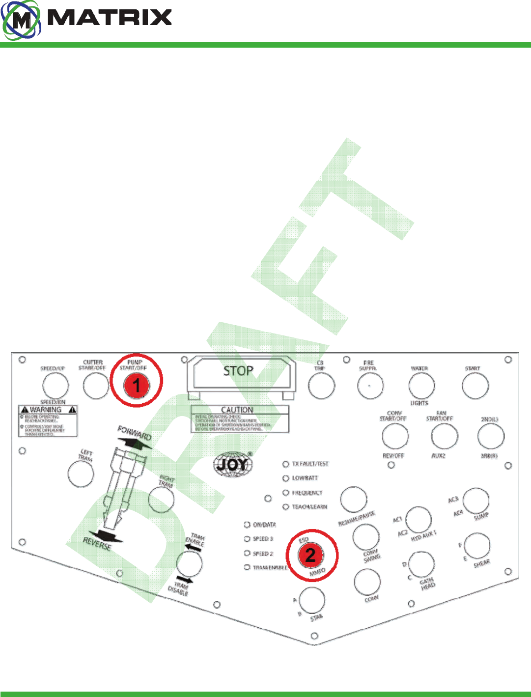
The IntelliZone™ Proximity Detection System features an ESO (Emergency Stop Override). This function is
only to be used in Emergency situations where the Proximity System must be bypassed. For Continuous
Miners this feature is activated with the machine’s remote control. This mode has limited functionality in that it
will only allow low speed tram. It is important that all miner operators and/or other personnel that come into
contact with the system daily know how this process works in the event of an emergency.
1. Toggle and hold the ESO/MMO switch ❷ in the ESO position.
2. Toggle and hold the Pump switch ❶.
3. Release the pump switch ❶, but continue to hold the ESO/MMO switch ❷ in the ESO position.
4. Activate the tram functions and move the machine to safe location.
5. Release the ESO switch to resume normal machine operation.
JOY C2C & DC Continuous Miner
Engineering Safety • Advancing Automation
29
10002008 rev 0
Matrix Design Group, LLC | 3299 Tower Drive Newburgh, IN 47630, USA | 812.490.1525 | www.matrixteam.com
Copyright © 2013 Matrix. All rights reserved. Do not distribute without prior consent.
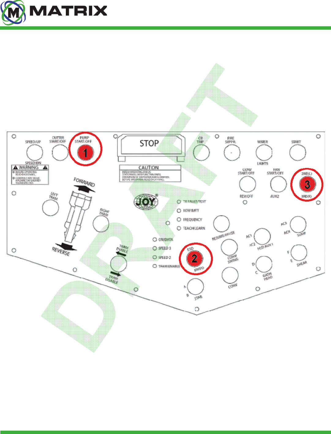
DO NOT DISTRIBUTE User Guide
1. Toggle and hold the ESO/MMO switch ❷ in the position.
2. Toggle and hold the Pump switch ❶and2ND/3RDswitch❸intheUPposion.
3. Release the pump switch ❶and2NDswitch❸, but continue to hold the ESO/MMO switch ❷ in the ESO position.
4. Activate the tram functions and move the machine to safe location.
5. Release the ESO switch to resume normal machine operation.
JOY JNA Continuous Miner
DO NOT DISTRIBUTE

Engineering Safety • Advancing Automation
30
10002008 rev 0
Matrix Design Group, LLC | 3299 Tower Drive Newburgh, IN 47630, USA | 812.490.1525 | www.matrixteam.com
Copyright © 2013 Matrix. All rights reserved. Do not distribute without prior consent.
DO NOT DISTRIBUTE
FCC Compliance
User Guide
US FCC Compliance Statements:
This device complies with Part 15 of the FCC Rules.
Operation is subject to the following two conditions:
1. This device may not cause harmful interference, and
2. This device must accept any interference received,
including interference that may cause undesired operation.
Changes or modifications not expressly approved by the party
responsible for compliance could void the user’s authority to
operate the equipment.
This equipment has been tested and found to comply with the limits for a Class B digital device, pursuant to Part15 of
the FCC Rules. These limits are designed to provide reasonable protection against harmful interference in a residential
installation. This equipment generates uses and can radiate radio frequency energy and, if not installed and used in
accordance with the instructions, may cause harmful interference to radio communications. However, there is no
guarantee that interference will not occur in a particular installation. If this equipment does cause harmful interference to
radio or television reception, which can be determined by turning the equipment off and on, the user is encouraged to try
to correct the interference by one of the following measures:
- Reorient or relocate the receiving antenna.
- Increase the separation between the equipment and receiver.
- Connect the equipment into an outlet on a circuit different from that
to which the receiver is connected.
- Consult the dealer or an experienced radio/TV technician for help.
This portable transmitter with its antenna complies with FCC/IC RF
exposure limits for general population / uncontrolled exposure.

Engineering Safety • Advancing Automation
31
10002008 rev 0
Matrix Design Group, LLC | 3299 Tower Drive Newburgh, IN 47630, USA | 812.490.1525 | www.matrixteam.com
Copyright © 2013 Matrix. All rights reserved. Do not distribute without prior consent.
DO NOT DISTRIBUTE
Canada IC Compliance / Canada États IC conformité
User Guide
Under Industry Canada regulations, this radio transmitter may only operate using an antenna of
a type and maximum (or lesser) gain approved for the transmitter by Industry Canada. To
reduce potential radio interference to other users, the antenna type and its gain should be so
chosen that the equivalent isotropically radiated power (e.i.r.p.) is not more than that necessary
for successful communication.
En vertu des règlements d'Industrie Canada, cet émetteur de radio ne peut fonctionner à l'aide d'une antenne d'un type
et le gain maximal (ou inférieur) approuvé pour l'émetteur par Industrie Canada. Pour réduire le risque d'interférence aux
autres utilisateurs, le type d'antenne et son gain doivent être choisis afin que la puissance isotrope équivalente (e.i.r.p)
rayonnée ne dépasse pas ce qui est nécessaire pour une communication réussie.
This Device complies with Industry Canada License-exempt RSS standard(s). Operation is
subject to the following two conditions: 1) this device may not cause interference, and 2) this
device must accept any interference, including interference that may cause undesired operation
of the device.
Cet appareil est conforme avec Industrie Canada RSS exemptes de licence standard (s). Son fonctionnement est
soumis aux deux conditions suivantes:
1) ce dispositif ne doit pas causer d'interférences, et
2) ce dispositif doit accepter toute interférence, y compris celles pouvant causer un mauvais fonctionnement de
l'appareil.
MX3-IZ Locator IDs
FCC ID:USK-10000615
IC ID:11898A-1000615