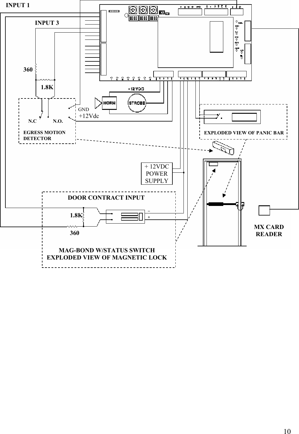
Matrix Systems 0114405 Keypad Proximity Reader User Manual 630202

Matrix Systems Inc Keypad Proximity Reader 630202

Users Manual

    RCM2 / MX-READER  INSTALLATION   MANUAL
 2The Reader Control Module is designed to interface with the Matrix family of card readers.  The RCM2 provides access control and alarm point monitoring for up to two separate portals,  providing entry and exit reader monitoring at each portal.
 3READER  CONTROL  MODULE  (RCM2)  AND  RELATED  COMPONENTS  The Reader Control Module,  model number 04-14000 is designed to interface with the Matrix family of card readers.  These include the magnetic stripe card readers: MX1, MX2,   and 01-14440 / 14441.   The RCM2 will also interface to the proximity family of card readers:  MX1-Prox,  MX2-Prox,    and the MX- iCLASS.  The RCM2 provides access control and alarm point monitoring for up to two separate portals, providing entry and exit reader monitoring at each portal.   WIRING CONSIDERATIONS  Wiring between devices must be installed in a professional manner using any applicable local and national codes and using the following suggestions  • For hollow wall construction, use ¾” electrical conduit or flexible metallic conduit. Minimally, the conduit should be extended from the reader location to above the ceiling. • For solid or hard surface construction, use ¾” electrical conduit or equally-sized metallic wire-mold. Plastic wire-way should not be used.  When wiring the RCM2 to the host system and portal devices, care should be taken in using the appropriate cable. Matrix Systems provides custom cable with either a PVC jacket, part number  53-12009, or a plenum-rated Teflon jacket, part number 53-12010, as shown in the figure below.               22 AWG wire with shield and drain wire.   Used for communications lines.               Green / White used for lock power.  18 AWG wire              Red / Black used for RCM / Reader power.
 4If substitute wire is used, it must meet the following criteria:  • 2-pair, 22 AWG, individually shielded, West Penn part number 430        (PVC jacket), or part number 25430 (plenum rated), or equivalent.        Use for RCM to Matrix host 4-wire RS-485 / 422 communications.  • 4-conductor, 18 AWG, West Penn part number 244 (PVC jacket),        or part number 25244 (plenum-rated), or equivalent. Use for Matrix host        (data) signal ground, + 12 vdc power, and RCM device lock power.  When explaining connections between devices, this manual will use the wire colors available with the Matrix Systems custom cable.   Typical installations  Control devices can be installed in a variety of configurations. The following pages lists samples of possible installations. Each of the following figures show how the respective device relates to the portal and other control devices. Typical conduit and wire usage is also shown in each figure. For specific information (mounting height, mounting method, wire color, etc.) refer to the sections:  • READER CONTROL MODULE  • MX-SERIES CARD READERS
 5                                         Sample Installation – Single Door with Magnetic Door Contact      RCM2 TO REMOTE DISTRIBUTION PANEL STUB ¾” CONDUIT INTO DOOR FRAME. INSTALL 1 WEST PENN #244 WIRE INTO CONDUIT INSTALL ¾” CONDUIT INSTALL 1 MATRIX 53-12009 CABLE DOOR POSITION SWITCH  NOTE: INSTALL ON SECURE SIDE OF DOOR. MAINTAIN MINIMUM OF 2” FROM OTHER DEVICES MOUNTED ON DOOR.
 6                                            Sample Installation – Single Door with Electric Strike,  MX Card Reader at Entrance and Exit Button at Exit. INSTALL ¾” CONDUIT INSTALL 1 MATRIX 53-12009 CABLE STUB ¾” CONDUIT INTO DOOR FRAME. INSTALL 1 WEST PENN #244 WIRE INTO CONDUIT DOOR POSITION SWITCH ELECTRIC STRIKE   INSTALL INTO DOOR FRAME. SEE INSTALLATION PROVIDED WITH LOCKS. EXIT BUTTON  RCM2 INSTALL 4”X4”X2-1/8” OUTLET BOX WITH DOUBLE GANG PLASTER RING FLUSH WITH OUTSIDE WALL SURFACE. INSTALL 1 WESTPENN #244 WIRE BETWEEN RCM AND EXIT BUTTON.INSTALL 4”X4”X2-1/8” OUTLET BOX WITH DOUBLE GANG PLASTER RING FLUSH WITH OUTSIDE WALL SURFACE. INSTALL 1 MATRIX 53-12009 CABLE BETWEEN RCM AND READER TO REMOTE DISTRIBUTION PANEL MX CARD READER
 7                                            Sample Installation – Single Door with Magnetic locks MX Card reader at Entrance and Motion Detector at Exit.  TO REMOTE DISTRIBUTION PANEL INSTALL 4”X4”X2-1/8” OUTLET BOX WITH DOUBLE GANG PLASTER RING FLUSH WITH OUTSIDE WALL SURFACE. INSTALL 1 MATRIX 53-12009 CABLE BETWEEN RCM AND READER RCM2MOTION DETECTOR INSTALL ¾” CONDUIT TO SINGLE GANG BOX AND INSTALL WEST PENN  #244 WIRE  STUB ¾” CONDUIT INTO DOOR FRAME. INSTALL 1 WEST PENN #244 WIRE DOOR POSITION SWITCH MAGLOCK MX CARD READER INSTALL ¾” CONDUIT INSTALL 1 MATRIX 53-12009 CABLE
 8                        Connector J6 is used for RS-422 communication with the host.  This is the default setting for the RCM2. Connector location on the RCM2 with input and output lines can be found in the Figure above.  Connector J8 is used for RS-232 modem communication with the host. The use of the modem requires changes from the default jumper settings of the RCM2. Refer to the SETUP section for setting of jumpers JP3 and JP6. Connector location on the RCM2 with input and output lines can be found in the Figure above.  Connector J10 is used to apply power to the RCM2. In most cases, power can be obtained from the RDP. If necessary, power from a local power supply can be connected to this connector.  Connectors J11 and J12 are used to connect the RCM2 to MX-Series card readers. Internally, the connectors are wired in parallel and can be used combination for ease of wiring. The distinction between card readers is done with software when the system is set up. However, it is recommended that the readers be connected as groups (first door pair connected at J11 and second door pair connected at J12) to simplify the system for future reference  J8 RS-232 J10 Power Input J11 READERS J12 READERS J6 RS-422
 9                                                   (TX)        BLUE      (RX)       WHITE   -12VDC       BLACK   +12VDC         RED   FRAME        DRAIN  GROUND     NOTE KEYWAY READER CONTROL MODULE (RCM2) MX CARD READER BACK VIEW Function       Color Code
 10             MX CARD READER + 12VDC POWER SUPPLYEXPLODED VIEW OF PANIC BAR MAG-BOND W/STATUS SWITCH EXPLODED VIEW OF MAGNETIC LOCK 360 DOOR CONTRACT INPUT 1.8K     N.C             N.O.  EGRESS MOTION DETECTOR INPUT 1 INPUT 3 1.8K 360   GND   +12Vdc
 11MX – SERIES  CARD  READERS  Matrix Systems Inc. manufactures and provides a variety of access control entry devices as an integral package to its RCM hardware.  With the MX Access Reader, magnetic stripe media badges may be used for portal entry. For higher security, a keypad PIN request can be used in conjunction with the use of the media badge.  The MX-Prox or proximity reader requires the user to simply present the badge to the device in close proximity. It may also request a PIN ID via the keypad if a higher security is required for access.   It should be noted that the reader devices do not actually control or grant access through a portal. This activity is controlled through the RCM.  Power and data connection required by the reader devices are provided by the RCM.   INSTALLATION  Installation of the MX-Series card readers require site inspection, mounting, wiring, and setup. In order to mount the card reader, a tamper screwdriver bit, Matrix part number 10-12002, is needed.  Site inspection  Site inspection determines the proper location and rough-in of the electrical boxes needed by the card readers. Considerations for conduit, wire, and general location of the card readers can be found in the WIRING CONSIDERATIONS and TYPICAL INSTALLATIONS of this manual. They can be mounted under a variety of conditions including new construction, existing hollow wall, hard surface interior wall, exterior wall, and pedestal. For all installations, the following precautions should be followed:  • One-inch clearance is needed around top and sides of the card reader.  • Allow an eight-inch clearance from bottom of card reader to allow installation and removal of tamper-resistant screw.
 12NOTE:  For all installations except pedestal or exterior hood-mount, card readers must be mounted to an electrical box that is plumb and securely attached to the mounting surface. Although the card reader utilizes low voltage power, the proper electrical box allows a secure installation of the card reader. In addition, if the card reader is not mounted properly, damage to its display could result during installation.   Interior Installation Rough-in  For interior wall installation, the card reader electrical box can be flush-mounted on hollow walls or surface-mounted on hard surfaces. For flush-mount, new construction, the card reader should be mounted to a four-inch square, (2-gang) outlet box with a four-inch switch ring sized to be flush with the wall surface, as shown in Figure below. For existing hollow walls, the card reader mounts on a standard, double gang, outlet box with mounting ears. For hard-surface-mount installations, Matrix wall boxes, part number 88-11943, are used to mount card readers.                                ¾” MINIMUM CONDUIT 4X4 BOX WITH 2-GANGPLASTER RINGMOUNTINGPLATE 6X32 THREAD 100 DEGREE FLAT HEAD SCREWCARD READER TAMPER-PROOF SCREW Removal tool P/N 10-12002
 13MX – SERIES  CARD  READERS                                 MX-Series Card reader Installation – Surface Mount
 14MX – SERIES  CARD  READERS    Exterior installation Rough-in  For exterior installation, card readers should be mounted in a Matrix weather environmental hood, part number 88-13007. When wall-mounted, drill a one-inch hole in the wall to accommodate the required cabling. The weather environmental hood is then installed to the wall as shown below.  The environmental hood can be pedestal-mounted for walk-up applications.
 15                                         MX-Series Card Reader Installation – Exterior Pedestal-Mount
 16Wiring the MX-Series Card Reader  To simplify wiring, the screw terminal connector may be removed from the back of the card reader. When attaching wires to the connector, note the location of the keyway and attach the wires as shown. When determining the wire length, be sure to allow enough wire to pull card reader away from the mounting surface to disconnect the connector.  Mounting the MX-Series Card Reader  Once the electrical box, conduit, and wiring have been installed, the card reader can be installed.  1. Position the mounting plate as shown.  2. Feed the cable and connector through the large hole in the mounting plate   CAUTION:  Do not over tighten the screws attaching the mounting plate. The mounting plate should be flat and flush with the wall. The mounting screws must also be completely recessed  into the mounting plate. This insures that the card reader will attach properly.  3. Attach the plate to the electrical box using four # 6-32 100 degree flat       head machine screws.  4. Connect connector to back of card reader.  5. While feeding cable back into the electrical box, align the card reader with the mounting plate slot that the four tabs on the back of the card reader engage the four slots in the mounting plate when the card reader is flush with the mounting plate, press down so that the card reader is locked in place.  6. Install the tamper-proof screw through the mounting plate and into the card  reader using the tamper screwdriver bit to complete the installation.
 17MX – SERIES  CARD  READER  The MX-Series card reader features a two-line LCD display, keyboard adjustable LCD contrast, and user-definable address selection. The reader is used with  the READER CONTROL MODULE (RCM) to allow access through two (2) doors at a time. This is accomplished by hanging a reader on each side of two doors (four readers in all). The door controller needs to identify these readers using a scheme which assigns an address to each individual reader. The  addressing is described below:   ADDRESS       FUNCTION        0                     DOOR 1 EGRESS        1                     DOOR 1 INGRESS        2                     DOOR 2 EGRESS        3                     DOOR 2 INGRESS  On the MX reader, the addresses are set through software and store into non-volatile memory. When the MX reader is off the wall (the tamper switch is tripped) and is powered up, the reader will identify itself with a sign-on message and then display a menu showing it is set to a cleared state. The menu will display:  Addr=C   (0-3) ?  A special address (address “C”) is used to identify a “cleared” reader. Because this address is invalid, the reader will not inadvertently come on-line until a proper address (address 0-3) is selected. Also, the reader will stay off-line until the contrast can be set to conform to the specific lighting of the new location. The valid keys that may be pressed in this mode are as follows:     KEY        FUNCTION       0   Sets the reader to address 0       1   Sets the reader to address 1       2   Sets the reader to address 2       3   Sets the reader to address 3  CLEAR  Sets the reader to cleared state. ENTER  Removes menu and displays STAND BY     4-9   Enter menu without changing the address.  A & D   Increases LCD contrast  B & C   Decreases LCD contrast     NOTE: As soon as a valid address key is pressed, the reader will come on-line and ALL of the previously mentioned features will cease to function until power is cycled. Even if power is lost and the reader is on the wall (the tamper switch in its normal position) these features will not be available again until power is cycled while it is off the wall.
 18User Information Concerning Radio and TV Interference   This equipment has been tested and found to comply with the limits for a Class A digital device according to the specifications in Part 15 of the FCC rules.  These rules are designed to provide reasonable protection from harmful interference in a commercial installation.   However,  there is no guarantee that interference will not occur in a particular installation.  If this equipment does cause interference to radio or television reception,  which can be determined by power cycling the device,  the user is encouraged to try to correct the interference by one or more of the following measures:  Moving the receiver away from this equipment. Powering the receiving equipment from a different AC outlet. Reposition or relocate the receiving antenna.   Changes to these card readers or RCM2 controller board that are not expressly approved in writing by Matrix Systems may void the end user’s authority to operate this equipment.  Operation is subject to the following two conditions: (1) this device may not cause interference, and (2) this device must accept any interference, including interference that may cause undesired operation of the device.    This equipment has been tested and found to comply with the limits for a Class A digital device, pursuant to Part 15 of the FCC Rules.  These limits are designed to provide reasonable protection against harmful interference when the equipment is operated in a commercial environment.  This equipment generates, uses, and can radiate radio frequency energy and, if not installed and used in accordance with the instruction manual, may cause harmful interference to radio communications.  Operation of this equipment in a residential area is likely to cause harmful interference in which case the user will be required to correct the interference at his own expense.

Navigation menu