MaxStream XBEE2 XBEE SERIES 2 OEM RF MODULE User Manual USERS MANUAL
MaxStream Inc. XBEE SERIES 2 OEM RF MODULE USERS MANUAL
UserManual.wiki
>
MaxStream
>
XBEE2 User Manual
>
USERS MANUAL
Contents
1.
USERS MANUAL
2.
Revised Used Manual
USERS MANUAL
Navigation menu
Upload a User Manual
Namespaces
Wiki Guide
HTML
PDF
Info
Views
User Manual
Discussion / Help
Navigation
![XBeeOEMRFModules‐ZigBee‐v1.x1x[2007.06.013]©2007DigiInternational,Inc. ii© 2007 Digi International, Inc. All rights reservedNopartofthecontentsofthismanualmaybetransmittedorreproducedinanyformorbyanymeanswithoutthewrittenpermissionofDigiInternational,Inc.ZigBee®isaregisteredtrademarkoftheZigBeeAlliance.XBee™Series2isatrademarkofDigiInternational,Inc.TechnicalSupport:Phone:(801)765‐9885LiveChat:www.maxstream.netE‐mail:rf‐xperts@maxstream.net](https://usermanual.wiki/MaxStream/XBEE2.USERS-MANUAL/User-Guide-814978-Page-2.png)
![ContentsXBee/XBee‐PROOEMRFModules‐ZigBee‐v1.x1x[2007.06.013]©2007DigiInternaitonal,Inc. iii1. XBee Series 2 OEM RF Modules 41.1. Key Features 41.1.1. Worldwide Acceptance 41.2. Specifications 51.3. Mechanical Drawings 61.4. Mounting Considerations 61.5. Pin Signals 71.6. Electrical Characteristics 82. RF Module Operation 92.1. Serial Communications 92.1.1. UART Data Flow 92.1.2. Serial Buffers 92.1.3. Transparent Operation 112.1.4. API Operation 112.2. Modes of Operation 122.2.1. Idle Mode 122.2.2. Transmit Mode 122.2.3. Receive Mode 132.2.4. Command Mode 132.2.5. Sleep Mode 143. ZigBee Networks 153.1. ZigBee Network Formation 153.1.1. Starting a ZigBee Coordinator 153.1.2. Joining a Router 153.1.3. Joining an End Device 163.2. ZigBee Network Communications 173.2.1. ZigBee Device Addressing 173.2.2. ZigBee Application-layer Addressing 173.2.3. Data Transmission and Routing 184. XBee Series 2 Network Formation 204.1. XBee Series 2 Network Formation 204.1.1. Starting an XBee Series 2 Coordinator 204.1.2. Joining an XBee Series 2 Router to an ex-isting PAN 204.1.3. Joining an XBee Series 2 End Device to an Existing PAN 204.1.4. Network Reset 214.2. XBee Series 2 Addressing 224.2.1. Device Addressing 224.2.2. Application-layer Addressing 234.2.3. XBee Series 2 Endpoint Table 254.3. Advanced Network Features 264.4. I.O. Line Configuration 275. XBee Series 2 Command Reference Tables296. API Operation 356.0.1. API Frame Specifications 356.0.2. API Types 367. Examples 457.0.1. Starting an XBee Network 457.0.2. AT Command Programming Examples 468. Manufacturing Support 478.1. Interoperability with other EM250 Devic-es 478.1.1. XBee Data Transmission and Reception 478.1.2. Customizing XBee Default Parameters 478.1.3. XBee Series 2 Custom Bootloader 47Definitions 48Migrating from the 802.15.4 Protocol 50 Agency Certifications 51Development Guide 55Additional Information 63](https://usermanual.wiki/MaxStream/XBEE2.USERS-MANUAL/User-Guide-814978-Page-3.png)
![©2007DigiInternational,Inc. 41.XBeeSeries2OEMRFModulesThe XBee Series 2 OEM RF Modules were engineered to operate within the ZigBee protocol and support the unique needs of low-cost, low-power wireless sensor networks. The modules require minimal power and provide reliable delivery of data between remote devices.The modules operate within the ISM 2.4 GHz frequency band.1.1. Key Features1.1.1. Worldwide AcceptanceFCC Approval (USA) Refer to Appendix A [p50] for FCC Requirements. Systems that contain XBee Series 2 RF Modules inherit MaxStream Certifications.ISM (Industrial, Scientific & Medical) 2.4 GHz frequency bandManufactured under ISO 9001:2000 registered standardsXBee Series 2 RF Modules are optimized for use in US, Canada, Australia, Israel and Europe (contact MaxStream for complete list of agency approvals).High Performance, Low Cost• Indoor/Urban: up to 133’ (40 m)• Outdoor line-of-sight: up to 400’ (120 m)• Transmit Power: 2 mW (+3 dBm)• Receiver Sensitivity: -95 dBmRF Data Rate: 250,000 bpsAdvanced Networking & SecurityRetries and AcknowledgementsDSSS (Direct Sequence Spread Spectrum)Each direct sequence channel has over 65,000 unique network addresses availablePoint-to-point, point-to-multipoint and peer-to-peer topologies supportedSelf-routing, self-healing and fault-tolerant mesh networkingLow PowerXBee Series 2• TX Current: 40 mA (@3.3 V)• RX Current: 40 mA (@3.3 V)• Power-down Current: < 1 µA @ 25oC Easy-to-UseNo configuration necessary for out-of box RF communicationsAT and API Command Modes for configuring module parametersSmall form factorExtensive command setFree X-CTU Software (Testing and configuration software)Free & Unlimited Technical Support](https://usermanual.wiki/MaxStream/XBEE2.USERS-MANUAL/User-Guide-814978-Page-4.png)
![XBeeSeries2OEMRFModules‐ZigBee‐v1.x1x[2007.06.013]©2007DigiInternational,Inc. 5Chapter1‐XBeeSeries2OEMRFModules1.2. SpecificationsAntenna Options: The ranges specified are typical when using the integrated Whip (1.5 dBi) and Dipole (2.1 dBi) antennas. The Chip antenna option provides advantages in its form factor; however, it typically yields shorter range than the Whip and Dipole antenna options when transmitting outdoors. For more information, refer to the “XBee Series 2 Antenna” application note located on MaxStream’s web site http://www.maxstream.net/support/knowledgebase/article.php?kb=153Table1‐01. SpecificationsoftheXBeeSeries2OEMRFModule(PRELIMINARY)Specification XBee Series 2PerformanceIndoor/Urban Range up to 133 ft. (40 m)Outdoor RF line-of-sight Range up to 400 ft. (120 m)Transmit Power Output (software selectable) 2.8 mW (+4.5 dBm)RF Data Rate 250,000 bpsSerial Interface Data Rate(software selectable)1200 - 230400 bps(non-standard baud rates also supported)Receiver Sensitivity -95 dBm (1% packet error rate)Power RequirementsSupply Voltage 2.8 – 3.4 VOperating Current (Transmit) 40mA (@ 3.3 V)Operating Current (Receive) 40mA (@ 3.3 V)Power-down Current < 1 uA @ 25oCGeneralOperating Frequency Band ISM 2.4 GHzDimensions 0.960” x 1.087” (2.438cm x 2.761cm)Operating Temperature -40 to 85º C (industrial)Antenna Options Integrated Whip, Chip, RPSMA, or U.FL ConnectorNetworking & SecuritySupported Network Topologies Point-to-point, Point-to-multipoint, Peer-to-peer & MeshNumber of Channels(software selectable) 16 Direct Sequence ChannelsAddressing Options PAN ID and Addresses, Cluster IDs and Endpoints (optional)Agency ApprovalsUnited States (FCC Part 15.247) PendingIndustry Canada (IC) PendingEurope (CE) Pending](https://usermanual.wiki/MaxStream/XBEE2.USERS-MANUAL/User-Guide-814978-Page-5.png)
![XBeeSeries2OEMRFModules‐ZigBee‐v1.x1x[2007.06.013]©2007DigiInternational,Inc. 6Chapter1‐XBeeSeries2OEMRFModules1.3. Mechanical DrawingsFigure1‐01. MechanicaldrawingsoftheXBeeSeries2OEMRFModules(antennaoptionsnotshown) .1.4. Mounting ConsiderationsThe XBee Series 2 RF Module (through-hole) was designed to mount into a receptacle (socket) and therefore does not require any soldering when mounting it to a board. The XBee Series 2 Development Kits contain RS-232 and USB interface boards which use two 20-pin receptacles to receive modules.Figure1‐02. XBeeSeries2ModuleMountingtoanRS‐232InterfaceBoard.The receptacles used on MaxStream development boards are manufactured by Century Interconnect. Several other manufacturers provide comparable mounting solutions; however, MaxStream currently uses the following receptacles:• Through-hole single-row receptacles - Samtec P/N: MMS-110-01-L-SV (or equivalent)• Surface-mount double-row receptacles - Century Interconnect P/N: CPRMSL20-D-0-1 (or equivalent)• Surface-mount single-row receptacles - Samtec P/N: SMM-110-02-SM-SMaxStream also recommends printing an outline of the module on the board to indicate the orientation the module should be mounted.XBee](https://usermanual.wiki/MaxStream/XBEE2.USERS-MANUAL/User-Guide-814978-Page-6.png)
![XBeeSeries2OEMRFModules‐ZigBee‐v1.x1x[2007.06.013]©2007DigiInternational,Inc. 7Chapter1‐XBeeSeries2OEMRFModules1.5. Pin SignalsFigure1‐03. XBeeSeries2RFModulePinNumber(topsidesshown‐shieldsonbottom)Design Notes:• Minimum connections: VCC, GND, DOUT & DIN• Minimum connections to support firmware upgrades: VCC, GND, DIN, DOUT, RTS & DTR• Signal Direction is specified with respect to the module• Module includes a 30k Ohm resistor attached to RESET• Several of the input pull-ups can be configured using the PR command• Unused pins should be left disconnectedTable1‐02. PinAssignmentsfortheXBeeSeries2Modules (Low‐assertedsignalsaredistinguishedwithahorizontallineabovesignalname.)Pin # Name Direction Description1 VCC - Power supply2 DOUT Output UART Data Out3 DIN / CONFIG Input UART Data In4 DIO8 Either Digital I/O 85RESET Input Module Reset (reset pulse must be at least 200 ns)6 PWM0 / RSSI / DIO10 Output PWM Output 0 / RX Signal Strength Indicator / Digital IO7 PWM / DIO11 Either Digital I/O 118 [reserved] - Do not connect9DTR / SLEEP_RQ/ DI8 Input Pin Sleep Control Line or Digital Input 810 GND - Ground11 DIO4 Either Digital I/O 412 CTS / DIO7 Either Clear-to-Send Flow Control or Digital I/O 713 ON / SLEEP Output Module Status Indicator14 [reserved] - Do not connect15 Associate / DIO5 Either Associated Indicator, Digital I/O 516 RTS / DIO6 Either Request-to-Send Flow Control, Digital I/O 617 AD3 / DIO3 Either Analog Input 3 or Digital I/O 318 AD2 / DIO2 Either Analog Input 2 or Digital I/O 219 AD1 / DIO1 Either Analog Input 1 or Digital I/O 120 AD0 / DIO0 Either Analog Input 0 or Digital I/O 0](https://usermanual.wiki/MaxStream/XBEE2.USERS-MANUAL/User-Guide-814978-Page-7.png)
![XBeeSeries2OEMRFModules‐ZigBee‐v1.x1x[2007.06.013]©2007DigiInternational,Inc. 8Chapter1‐XBeeSeries2OEMRFModules1.6. Electrical CharacteristicsTable1‐03. DCCharacteristicsoftheXBeeSeries2(VCC=2.8‐3.4VDC)Symbol Parameter Condition Min Typical Max UnitsVIL Input Low Voltage All Digital Inputs - - 0.2 * VCC VVIH Input High Voltage All Digital Inputs 0.8 * VCC - 0.18* VCC VVOL Output Low Voltage IOL = 2 mA, VCC >= 2.7 V - - 0.18*VCC VVOH Output High Voltage IOH = -2 mA, VCC >= 2.7 V 0.82*VCC - - VIIIN Input Leakage Current VIN = VCC or GND, all inputs, per pin - - 0.5uA uATX Transmit Current VCC = 3.3 V - 45 - mARX Receive Current VCC = 3.3 V - 50 - mAPWR-DWN Power-down Current SM parameter = 1 - < 10 - uA](https://usermanual.wiki/MaxStream/XBEE2.USERS-MANUAL/User-Guide-814978-Page-8.png)
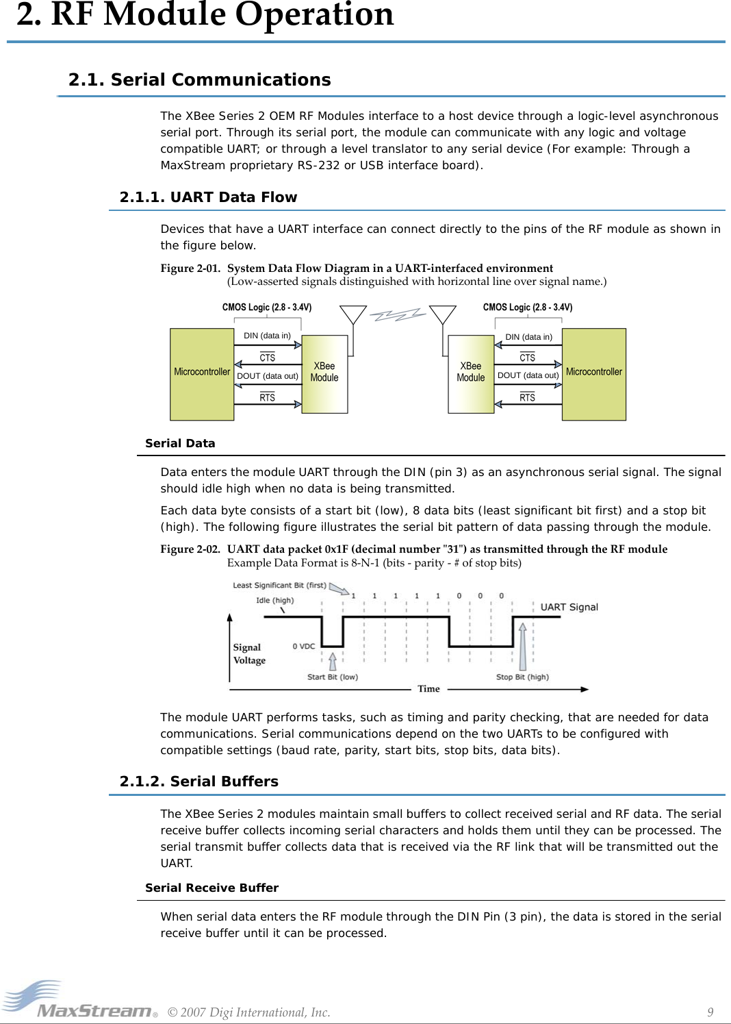
![XBee/XBee‐PROOEMRFModules‐ZigBee‐v1.x1x[2007.06.013]©2007DigiInternational,Inc. 10Chapter2‐RFModuleOperationHardware Flow Control (CTS). When the serial receive buffer is 17 bytes away from being full, by default, the module de-asserts CTS (high) to signal to the host device to stop sending data [refer to D7 (DIO7 Configuration) parameter]. CTS is re-asserted after the serial receive buffer has 34 bytes of memory available.Cases in which the serial receive buffer may become full and possibly overflow:Serial Transmit BufferWhen RF data is received, the data is moved into the serial transmit buffer and is sent out the serial port. If the serial transmit buffer becomes full enough such that all data in a received RF packet won’t fit in the serial transmit buffer, the entire RF data packet is dropped.Hardware Flow Control (RTS). If RTS is enabled for flow control (D6 (DIO6 Configuration) Parameter = 1), data will not be sent out the serial transmit buffer as long as RTS (pin 16) is de-asserted.Cases in which the serial transmit buffer may become full resulting in dropped RF packetsFigure2‐03. InternalDataFlowDiagram1. If the module is receiving a continuous stream of RF data, any serial data that arrives on the DIN pin is placed in the serial receive buffer. The data in the serial receive buffer will be transmitted over-the-air when the module is no longer receiving RF data in the network.2. When data is ready to be transmitted, the module may need to discover a Network Address and/or a Route in order to reach the destination node. Discovery overhead may delay packet transmission. Refer to the ZigBee Networks --> Mesh Routing sections for more information.1. If the RF data rate is set higher than the interface data rate of the module, the module could receive data faster than it can send the data to the host.2. If the host does not allow the module to transmit data out from the serial transmit buffer because of being held off by hardware flow control.Serial Receive BufferSerial Transmit Buffer](https://usermanual.wiki/MaxStream/XBEE2.USERS-MANUAL/User-Guide-814978-Page-10.png)
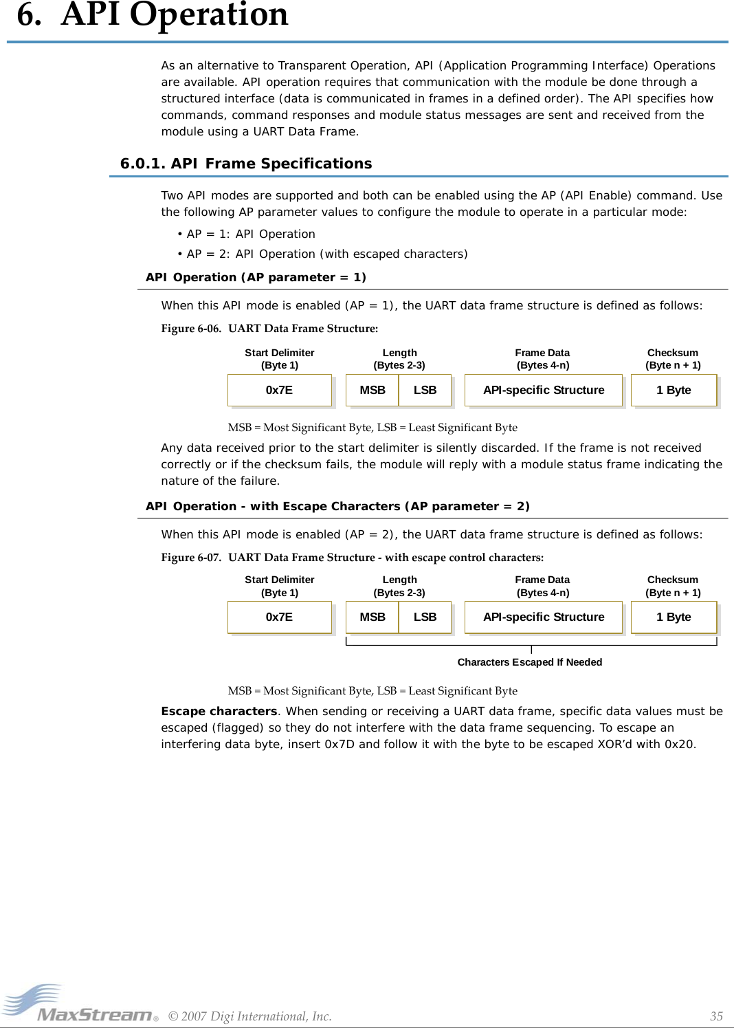
![XBee/XBee‐PROOEMRFModules‐ZigBee‐v1.x1x[2007.06.013]©2007DigiInternational,Inc. 11Chapter2‐RFModuleOperation2.1.3. Transparent OperationRF modules that contain the following firmware versions will support Transparent Mode: 1.0xx (coordinator) and 1.2xx (router/end device).When operating in Transparent Mode, modules are configured using AT Commands and API operation is not supported. The modules act as a serial line replacement - all UART data received through the DIN pin is queued up for RF transmission. Data is sent to a module as defined by the DH (Destination Address High) and DL (Destination Address Low) parameters. When RF data is received by a module, the data is sent out the DOUT pin.Serial-to-RF PacketizationData is buffered in the serial receive buffer until one of the following causes the data to be packetized and transmitted:2.1.4. API OperationAPI (Application Programming Interface) Operation is an alternative to the default Transparent Operation. The frame-based API extends the level to which a host application can interact with the networking capabilities of the module. RF modules that contain the following firmware versions will support API operation: 1.1xx (coordinator) and 1.3xx (router/end device).When in API mode, all data entering and leaving the module is contained in frames that define operations or events within the module.Transmit Data Frames (received through the DIN pin (pin 3)) include:• RF Transmit Data Frame• Command Frame (equivalent to AT commands)Receive Data Frames (sent out the DOUT pin (pin 2)) include:• RF-received data frame• Command response• Event notifications such as reset, associate, disassociate, etc.The API provides alternative means of configuring modules and routing data at the host application layer. A host application can send data frames to the module that contain address and payload information instead of using command mode to modify addresses. The module will send data frames to the application containing status packets; as well as source, and payload information from received data packets.The API operation option facilitates many operations such as the examples cited below:To implement API operations, refer to the API Operation chapter 6.1. No serial characters are received for the amount of time determined by the RO (Packetiza-tion Timeout) parameter. If RO = 0, packetization begins when a character is received.2. Maximum number of characters that will fit (72) in an RF packet is received.3. The Command Mode Sequence (GT + CC + GT) is received. Any character buffered in the serial receive buffer before the sequence is transmitted.-> Transmitting data to multiple destinations without entering Command Mode-> Receive success/failure status of each transmitted RF packet-> Identify the source address of each received packet](https://usermanual.wiki/MaxStream/XBEE2.USERS-MANUAL/User-Guide-814978-Page-11.png)
![XBee/XBee‐PROOEMRFModules‐ZigBee‐v1.x1x[2007.06.013]©2007DigiInternational,Inc. 12Chapter2‐RFModuleOperation2.2. Modes of Operation2.2.1. Idle ModeWhen not receiving or transmitting data, the RF module is in Idle Mode. During Idle Mode, the RF module is also checking for valid RF data. The module shifts into the other modes of operation under the following conditions:• Transmit Mode (Serial data in the serial receive buffer is ready to be packetized)• Receive Mode (Valid RF data is received through the antenna)• Sleep Mode (End Devices only)• Command Mode (Command Mode Sequence is issued)2.2.2. Transmit ModeWhen serial data is received and is ready for packetization, the RF module will exit Idle Mode and attempt to transmit the data. The destination address determines which node(s) will receive the data. Prior to transmitting the data, the module ensures that a 16-bit Network Address and route to the destination node have been established. If the 16-bit Network Address is not known, Network Address Discovery will take place. If a route is not known, route discovery will take place for the purpose of establishing a route to the destination node. If a module with a matching Network Address is not discovered, the packet is discarded. The data will be transmitted once a route is established. If route discovery fails to establish a route, the packet will be discarded. Figure2‐04. TransmitModeSequenceWhen data is transmitted from one node to another, a network-level acknowledgement is transmitted back across the established route to the source node. This acknowledgement packet indicates to the source node that the data packet was received by the destination node. If a network acknowledgement is not received, the source node will re-transmit the data. See Data Transmission and Routing in chapter 3 for more information.16-bit NetworkAddress DiscoveryData DiscardedSuccessfulTransmissionYesNoNewTransmission16-bit NetworkAddress Discovered?Route Known?Route Discovered?16-bit NetworkAddress Known?Route DiscoveryTransmit DataIdle ModeNoYesNo NoYes Yes](https://usermanual.wiki/MaxStream/XBEE2.USERS-MANUAL/User-Guide-814978-Page-12.png)
![XBee/XBee‐PROOEMRFModules‐ZigBee‐v1.x1x[2007.06.013]©2007DigiInternational,Inc. 13Chapter2‐RFModuleOperation2.2.3. Receive ModeIf a valid RF packet is received and its address matches the RF module’s MY (16-bit Source Address) parameter, the data is transferred to the serial transmit buffer.2.2.4. Command ModeTo modify or read RF Module parameters, the module must first enter into Command Mode - a state in which incoming serial characters are interpreted as commands. Refer to the API Mode section for an alternate means of configuring modules.AT Command ModeTo Enter AT Command Mode:Default AT Command Mode Sequence (for transition to Command Mode):• No characters sent for one second [GT (Guard Times) parameter = 0x3E8]• Input three plus characters (“+++”) within one second [CC (Command Sequence Character) parameter = 0x2B.]• No characters sent for one second [GT (Guard Times) parameter = 0x3E8]All of the parameter values in the sequence can be modified to reflect user preferences.NOTE: Failure to enter AT Command Mode is most commonly due to baud rate mismatch. Ensure the ‘Baud’ setting on the “PC Settings” tab matches the interface data rate of the RF module. By default, the BD parameter = 3 (9600 bps).To Send AT Commands:Figure2‐05.SyntaxforsendingATCommandsTo read a parameter value stored in the RF module’s register, omit the parameter field.The preceding example would change the RF module Destination Address (Low) to “0x1F”. To store the new value to non-volatile (long term) memory, subsequently send the WR (Write) command.For modified parameter values to persist in the module’s registry after a reset, changes must be saved to non-volatile memory using the WR (Write) Command. Otherwise, parameters are restored to previously saved values after the module is reset.System Response. When a command is sent to the module, the module will parse and execute the command. Upon successful execution of a command, the module returns an “OK” message. If execution of a command results in an error, the module returns an “ERROR” message.To Exit AT Command Mode:Send the 3-character command sequence “+++” and observe guard times before and after the command characters. [Refer to the “Default AT Command Mode Sequence” below.]Send AT commands and parameters using the syntax shown below.1. Send the ATCN (Exit Command Mode) command (followed by a carriage return). [OR]2. If no valid AT Commands are received within the time specified by CT (Command Mode Timeout) Command, the RF module automatically returns to Idle Mode.](https://usermanual.wiki/MaxStream/XBEE2.USERS-MANUAL/User-Guide-814978-Page-13.png)
![XBee/XBee‐PROOEMRFModules‐ZigBee‐v1.x1x[2007.06.013]©2007DigiInternational,Inc. 14Chapter2‐RFModuleOperationFor an example of programming the RF module using AT Commands and descriptions of each configurable parameter, refer to the "RF Module Configuration" chapter.2.2.5. Sleep ModeSleep modes are supported on end devices only. Router and coordinator devices participate in routing data packets and are intended to be mains powered. End devices must be joined to a parent (router or coordinator) before they can participate on a ZigBee network. The parent device does not track when an end device is awake or asleep. Instead, the end device must inform the parent when it is able to receive data. The parent must be able to buffer incoming data packets destined for the end device until the end device can awake and receive the data. When an end device is able to receive data, it sends a poll command to the parent. When the parent router or coordinator receives the poll command, it will transmit any buffered data packets for the end device. Routers and coordinators are capable of buffering one broadcast transmission for sleeping end device children.The SM, ST, SP, and SN commands are used to configure sleep mode operation.Data ManagementThe SP command on the parent determines how long the parent will buffer a packet. It should be set to match the maximum SP value on any end device that may join to it. SP can be set up to 28 seconds (0xAF0). End Device Sleep ModesPin SleepSetting SM=1 or SM=2 configures a device as a pin-sleep enabled end device. When operating in this mode, an end device monitors the Sleep_Request pin for a high state. When Sleep_Request goes high, the module enters sleep mode once any pending transmissions have finished. The module remains in a low power state until the Sleep_Request pin goes low. When the module wakes from pin sleep, it sends a poll request to the parent to see if any data is pending for the end device. Since routers and coordinators can only buffer data up to 30 seconds, end devices should not remain in pin sleep longer than about 28 seconds if incoming data packets must be received. Using pin sleep for more than 28 seconds is recommended only if incoming data packets are not expected.When the module wakes from a pin sleep mode, the CTS line goes low, and On/Sleep goes high.Cyclic SleepCyclic sleep allows the end device to sleep for a specified period of time. The period of time is specified by SP. Since routers and coordinators can only buffer data packets for up to 30 seconds, SP on end devices can be set up to 28 seconds (0xAF0). The module will wake after SP time and send a poll request to the parent to check for data. If any serial or RF data is received, the ST time is restarted. Once ST time has expired with no serial or RF activity, the end device will resume cyclic sleep operation.When the module wakes, CTS goes low allowing the application to send serial data to the module if necessary. The On/Sleep indicator will be set high to alert the application that the end device has awakened. If serial or RF data is received, the ST timer will be reset, otherwise, the end device will resume low power operation.Off board peripherals may wish to sleep longer than the maximum SP time of the end device. The SN command can be used to not wake off board peripherals for longer than SP time.For example, if SP=28 seconds, and SN=5, the end device will wake up every 28 seconds and poll the parent for data. If no data is pending, the end device will return to sleep. In this example, if the parent has no data for the end device, On/Sleep will go high after 140 seconds, assuming the parent never has data for the end device. If the parent has data for the end device, On/Sleep will go high and the SN counter will reset.](https://usermanual.wiki/MaxStream/XBEE2.USERS-MANUAL/User-Guide-814978-Page-14.png)
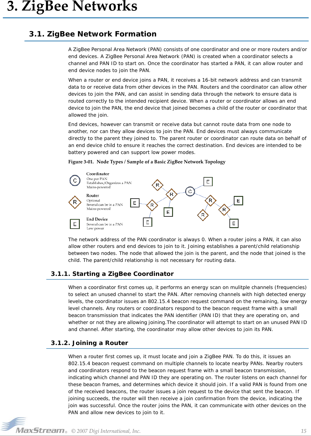
![XBee/XBee‐PROOEMRFModules‐ZigBee‐v1.x1x[2007.06.013]©2007DigiInternational,Inc. 16Chapter3‐ZigBeeNetworks3.1.3. Joining an End DeviceWhen an end device first comes up, it must also locate and join a PAN. End devices follow the same process as a router to join a PAN. Once the end device has successfully joined a PAN, it can communicate with other devices on the PAN. However, since end devices cannot route data, it must always communicate directly with its parent and allow the parent to route data in its behalf.Figure3‐02. DemonstrationofBeaconRequestandBeacontransmissionsthattakeplaceduringjoining.](https://usermanual.wiki/MaxStream/XBEE2.USERS-MANUAL/User-Guide-814978-Page-16.png)
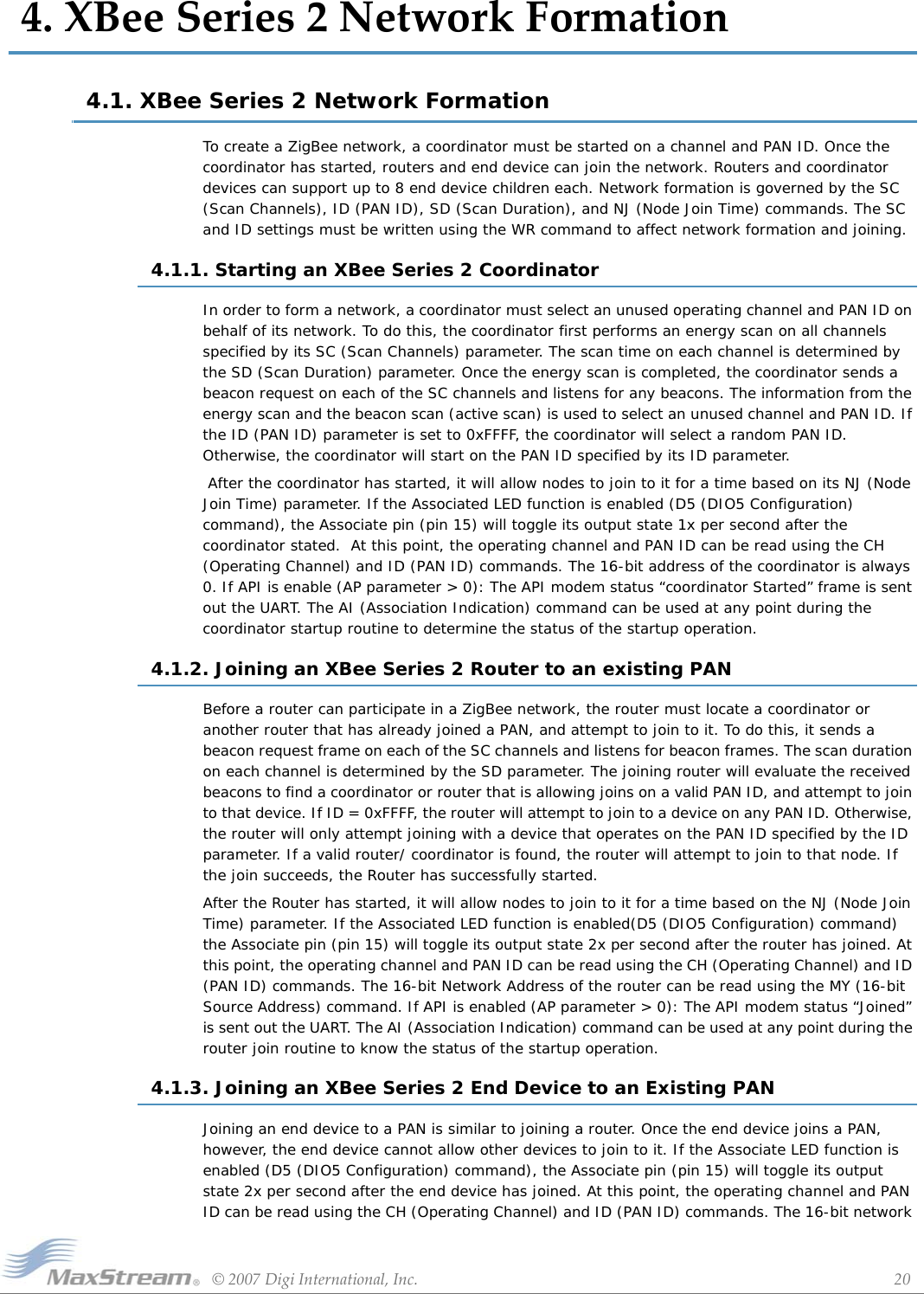
![XBee/XBee‐PROOEMRFModules‐ZigBee‐v1.x1x[2007.06.013]©2007DigiInternational,Inc. 17Chapter3‐ZigBeeNetworks3.2. ZigBee Network CommunicationsZigbee supports device addressing and application layer addressing. Device addressing specifies the destination address of the device a packet is destined to. Application layer addressing indicates a particular application recipient, known as a Zigbee endpoint, along with message type fields called cluster IDs. 3.2.1. ZigBee Device AddressingThe 802.15.4 protocol upon which the ZigBee protocol is built specifies two address types:• 16-bit Network Addresses• 64-bit Addresses16-bit Network AddressesA 16-bit Network Address is assigned to a node when the node joins a network. The Network Address is unique to each node in the network. However, Network Addresses are not static - it can change.The following two conditions will cause a node to receive a new Network Address:ZigBee requires that data be sent to the 16-bit network address of the destination device. This requires that the 16-bit address be discovered before transmitting data. See 3.2.3 Network Address Discovery for more information.64-bit AddressesEach node contains a unique 64-bit address. The 64-bit address uniquely identifies a node and is permanent.3.2.2. ZigBee Application-layer AddressingThe ZigBee application layers define endpoints and cluster identifiers (cluster IDs) that are used to address individual services or applications on a device. An endpoint is a distinct task or application that runs on a ZigBee device, similar to a TCP port. Each ZigBee device may support one or more endpoints. Cluster IDs define a particular function or action on a device. Cluster IDs in the ZigBee home controls lighting profile, for example, would include actions such as “TurnLightOn”, “TurnLightOff”, “DimLight”, etc.Suppose a single radio controls a light dimmer and one or more light switches. The dimmer and switches could be assigned to different endpoint values. To send a message to the dimmer, a remote radio would transmit a message to the dimmer endpoint on the radio. In this example, the radio might support cluster IDs to “TurnLightOn”, “TurnLightOff”, or “DimLight”. Thus, for radio A to turn off a light on radio B, radio A would send a transmission to the light switch endpoint on radio B, using cluster ID “TurnLightOff”. This is shown in the figure below.1. If an end device cannot communicate with its parent it may need to leave the network and rejoin to find a new parent. 2. If the device type changes from router to end device, or vice-versa, the device will leave the network and rejoin as the new device type.](https://usermanual.wiki/MaxStream/XBEE2.USERS-MANUAL/User-Guide-814978-Page-17.png)
![XBee/XBee‐PROOEMRFModules‐ZigBee‐v1.x1x[2007.06.013]©2007DigiInternational,Inc. 18Chapter3‐ZigBeeNetworksFigure3‐03. ZigBeeDataTransmissionHigherLayerAddressingFieldsFigure3‐04. ZigBeeLayer‐AddressingExample3.2.3. Data Transmission and RoutingAll data packets are addressed using both device and application layer addressing fields. Data can be sent as a broadcast, multicast, or unicast transmission.Broadcast TransmissionsBroadcast transmissions within the ZigBee protocol are intended to be propagated throughout the entire network such that all nodes receive the transmission. To accomplish this, all devices that receive a broadcast transmission will retransmit the packet 3 times. Each node that transmits the broadcast will also create an entry in a local broadcast transmission table. This entry is used to keep track of each received broadcast packet to ensure the packets are not endlessly transmitted. Each entry persists for 8 seconds. The broadcast transmission table holds 8 entries.Since broadcast transmissions are retransmitted by each device in the network, broadcast messages should be used sparingly.Multicast TransmissionsMulticast transmissions operate similar to broadcast transmissions. Data packets are broadcast throughout the network in a similar fashion. However, only devices that are part of the multicast group will receive the data packets.Unicast TransmissionsUnicast ZigBee transmissions are always addressed to the 16-bit address of the destination device. However, only the 64-bit address of a device is permanent; the 16-bit address can change. Therefore, ZigBee devices may employ network address discovery to identify the current 16-bit Src Address Dest Address Profile ID Src EndpointDest Endpoint Cluster IDNetwork Layer Application Support LayerEndpoint 1Endpoint 3(radio A)Endpoint 2Endpoint 40Endpoint 41(radio B)Endpoint 42Cluster ID = TurnLightOffZigBee Device A ZigBee Device B](https://usermanual.wiki/MaxStream/XBEE2.USERS-MANUAL/User-Guide-814978-Page-18.png)
![XBee/XBee‐PROOEMRFModules‐ZigBee‐v1.x1x[2007.06.013]©2007DigiInternational,Inc. 19Chapter3‐ZigBeeNetworksaddress that corresponds to a known 64-bit address. Once the 16-bit address is known, a route to the destination device must be discovered. ZigBee employs mesh routing using the Ad-hoc On-demand Distance Vector routing (AODV) protocol to establish a route between the source device and the destination. Network Address DiscoveryData transmissions are always sent to the 16-bit network address of the destination device. However, since the 64-bit address is unique to each device and is generally known, ZigBee devices must discover the network address that was assigned to a particular device when it joined the PAN before they can transmit data. To do this, the device initiating a transmission sends a broadcast network address discovery transmission throughout the network. This packet contains the 64-bit address of the device the initiator needs to send data to. Devices that receive this broadcast transmission check to see if their 64-bit address matches the 64-bit address contained in the broadcast transmission. If the addresses match, the device sends a response packet back to the initiator, providing the network address of the device with the matching 64-bit address. When this response is received, the initiator can then transmit data.Mesh RoutingMesh routing allows data packets to traverse multiple nodes (hops) in a network to route data from a source to a destination. The route a packet can take in a mesh network is independent of the parent/child relationships established during joining. Before transmitting a data packet from source to destination nodes, a route must be established. Route discovery is based on the AODV (Ad-hoc On-demand Distance Vector routing) protocol.AODV (Ad-hoc On-demand Distance Vector) Routing AlgorithmRouting under the AODV protocol is accomplished using tables in each node that store in the next hop (intermediary node between source and destination nodes) for a destination node. If a next hop is not known, route discovery must take place in order to find a path. Since only a limited number of routes can be stored on a Router, route discovery will take place more often on a large network with communication between many different nodes.When a source node must discover a route to a destination node, it sends a broadcast route request command. The route request command contains the source Network Address, the destination Network Address and a Path Cost field (a metric for measuring route quality). As the route request command is propagated through the network (refer to the Broadcast Transmission), each node that re-broadcasts the message updates the Path Cost field and creates a temporary entry in its route discovery table. When the destination node receives a route request, it compares the ‘path cost’ field against previously received route request commands. If the path cost stored in the route request is better than any previously received, the destination node will transmit a route reply packet to the node that originated the route request. Intermediate nodes receive and forward the route reply packet to the Source Node (the node that originated route request).Retries and AcknowledgmentsZigBee includes acknowledgment packets at both the Mac and Application Support (APS) layers. When data is transmitted to remote device, it may traverse multiple hops to reach the destination. As data is transmitted from one node to its neighbor, an acknowledgment packet (Ack) is transmitted in the opposite direction to indicate that the transmission was successfully received. If the Ack is not received, the transmitting device will retransmit the data, up to 4 times. This Ack is called the Mac layer acknowledgment.In addition, the device that originated the transmission expects to receive an acknowledgment packet (Ack) from the destination device. This Ack will traverse the same path that the data traversed, but in the opposite direction. If the originator fails to receive this Ack, it will retransmit the data, up to 2 times until an Ack is received. This Ack is called the ZigBee APS layer acknowledgment.Refer to the ZigBee specification for more details.](https://usermanual.wiki/MaxStream/XBEE2.USERS-MANUAL/User-Guide-814978-Page-19.png)
![XBee/XBee‐PROZigBeeOEMRFModulesv1.x1x[2007.06.013]©2007DigiInternational,Inc. 21Chapter4‐RFModuleConfigurationaddress of the end device can be read using the MY (16-bit Source Address) command. If API is enabled (AP parameter > 0), the API modem status “Joined” is sent out the UART. The AI (Association Indication) command can be used at any point during the end device join routine to know the status of the startup operation.4.1.4. Network ResetOnce a coordinator has started, or a router or end device has joined the network, the device will continue operating on that channel and PAN ID unless one of the following occurs:1. The ID parameter changes, and is saved using the WR command2. The SC parameter changes and is saved using the WR command, such that the current operating channel is not included in the new SC parameter3. The NR command is issued with either 0 or 1 as a parameterIf any of the above occurs on a coordinator, the coordinator will attempt to restart on a channel and PAN ID based on the new saved ID and SC commands. On a router or end device, the above conditions will cause the device to leave the network (if previously joined) and attempt to join a new PAN using the saved ID and SC parameters.](https://usermanual.wiki/MaxStream/XBEE2.USERS-MANUAL/User-Guide-814978-Page-21.png)
![XBee/XBee‐PROZigBeeOEMRFModulesv1.x1x[2007.06.013]©2007DigiInternational,Inc. 22Chapter4‐RFModuleConfiguration4.2. XBee Series 2 AddressingXBee modules support both ZigBee device addressing and application-layer addressing. 4.2.1. Device AddressingAll XBee/XBee-Pro modules can be identified by their unique 64-bit adresses or a user-configurable ASCII string identifier The 64-bit address of a module can read using the SH and SL commands. The ASCII string identifier is configured using the NI command. To transmit using device addressing, only the destination address must be configured. The destination address can be specified using either the destination device’s 64-bit address or its NI-string. The XBee modules also support coordinator and broadcast addressing modes. Device addressing in the AT firmware is configured using the DL, DH, or DN commands. In the API firmware, the ZigBee Transmit Request API frame (0x10) can be used to specify destination addresses.64-Bit AddressingTo address a node by its 64-bit address, the destination 64-bit address must be set to match the 64-bit address of the remote. In the AT firmware, the DH and DL commands set the destination 64-bit address. In the API firmware, the destination 64-bit address is set in the ZigBee Transmit Request frame. The coordinator can be addressed by either setting the destination address to 0 or by setting it to match the coordinator's 64-bit address. Broadcast transmissions can be sent by setting the 64-bit address to 0x000000000000FFFF.To send a packet to an RF module using its 64-bit Address (Transparent Mode)To send a packet to an RF module using its 64-bit Address (API Mode)Since the ZigBee protocol relies on the 16-bit Network Address for routing, the 64-bit address must be converted into a 16-bit Network Address prior to transmitting data. If a module does not know the 16-bit Network Address for a given 64-bit address, it will transmit a broadcast Network Address Discovery command. The module with a matching 64-bit address will transmit its 16-bit network address back. Once the network address is discovered, the data will be transmitted.The modules maintain a table that can store up to seven 64-bit addresses and their corresponding 16-bit Network Addresses.API AddressingAPI Mode provides the ability to store and maintain 16-bit Network Address tables on an external processor. The 16-bit Network Address information is provided to the application through the following:•The ZigBee Transmit Status Frame (contains the current 16-bit Network Address of the remote)• The ND and DN commands (return 64-bit and 16-bit Network Addresses of remote nodes)With this information, a table can be built in an application that maps a 64-bit Address to the corresponding 16-bit Network Address. The ZigBee Transmit Request API frame specifies the 64-bit Address and the Network Address (if known) that the packet should be sent to. By supplying both addresses, the module will forego Network Address Discovery and immediately attempt to route the data packet to the remote. If the Network Address of a particular remote changes, Network Address and route discovery will Set the DH (Destination Address High) and DL (Destination Address Low) parameters of the source node to match the 64-bit Address (SH (Serial Number High) and SL (Serial Number Low) parameters) of the destination node.Use the ZigBee Transmit Request API frame to set the DH (Destination Address High) and DL (Destination Address Low) parameters of the source node to match the 64-bit Address (SH (Serial Number High) and SL (Serial Number Low) parameters) of the destination node.If the 16-bit address of the destination node is not known, set 16-bit Destination Network Address to 0xFFFE (refer to the ‘API Addressing section below).](https://usermanual.wiki/MaxStream/XBEE2.USERS-MANUAL/User-Guide-814978-Page-22.png)
![XBee/XBee‐PROZigBeeOEMRFModulesv1.x1x[2007.06.013]©2007DigiInternational,Inc. 23Chapter4‐RFModuleConfigurationtake place to establish a new route to the correct node. Upon successful packet delivery, the TX Status Frame will indicate the correct Network Address of the remote.NI-String AddressingThe NI string can alternatively be used to address a remote module. To send a packet to an RF module using its NI-string (Transparent Mode)To send a packet to an RF module using its NI-string (API Mode)When the DN command is issued, a broadcast transmission is sent across the network to discover the module that has a matching NI (Node Identifier) parameter. If a module is discovered with a matching NI-string, the DH and DL parameters will be configured to address the destination node and the command will return both the 64-bit Address and the 16-bit Network Address of the discovered node. Data can be transmitted after the DN (Destination Node) command finishes.the AO command. See “API Frames” section for details.Coordinator AddressingA Coordinator can be addressed using its 64-bit address or NI string as described in the “NI-String Addressing” section. Alternatively, since the ZigBee Coordinator has a Network Address of “0”, it can be addressed by its 16-bit Network Address.To send a transmission to a Coordinator using its 16-bit Network Address: Broadcast AddressingBroadcast transmissions are sent using a 64-bit address of 0x0000FFFF. Any RF module in the PAN will accept a packet that contains a broadcast address. When configured to operate in Broadcast Mode, receiving modules do not send ACKs (Acknowledgements).To send a broadcast packet to all modulesNOTE: When programming the module, parameters are entered in hexadecimal notation (without the “0x” prefix). Leading zeros may be omitted.Refer to the “Broadcast Transmissions” for more information.4.2.2. Application-layer AddressingApplication-layer addressing allows the application to specify endpoint and cluster ID values for each transmission. Addressing multiple endpoints and cluster IDs can be accomplished by explicitly setting these values as needed.Table4‐01. Sampletablemapping64‐bitAddressesto16‐bitNetworkAddressesIndex 64-bit Address 16-bit Network Address0 0013 4000 4000 0001 12341 0013 4000 4000 0002 56782 0013 4000 4000 01A0 A4793 0013 4000 4000 0220 1F70Issue the DN (Destination Node) command using the NI (Node Identifier)-string of the destina-tion node as the parameter.Issue the DN command as stated above using the AT Command API frame. Set the Destination Addresses of the transmitting module as shown below:DL (Destination Low Address) = 0 DH (Destination High Address) = 0Set the Destination Addresses of the transmitting module as shown below:DL (Destination Low Address) = 0x0000FFFF DH (Destination High Address) = 0x00000000](https://usermanual.wiki/MaxStream/XBEE2.USERS-MANUAL/User-Guide-814978-Page-23.png)
![XBee/XBee‐PROZigBeeOEMRFModulesv1.x1x[2007.06.013]©2007DigiInternational,Inc. 24Chapter4‐RFModuleConfigurationIn AT firmware, application-layer addressing must be enabled using the ZA command. When application-layer addressing is enabled, the DE and SE commands specify the source and destination endpoints, and the CI command sets the cluster ID that will be used in the transmission.In API firmware, the Explicit Addressing ZigBee Command frame (0x11) can be used to configure the endpoint and cluster ID addressing parameters as needed. The destination device can indicate application-layer addressing information if the Explicit Receive API frame is addressing information using either the explicit receive indicator or the binding receive API frames. The receive RF data frame is set using Binding Table AddressingThe XBee Series 2 modules maintain several entries in a binding table. The binding table contains a destination 64-bit address, a type field, and endpoints for each transmission. Non-broadcast transmissions make use of the binding table to specify the addressing values for the transmission. Some entries in the binding table are reserved by MaxStream for special purposes. Binding table entries can be accessed by setting the BI command to a valid index in AT firmware, or by using the Binding Table API Command frame in the API firmware. The binding table entries are organized as follows.Coordinator BindingThe coordinator binding contains the 64-bit address of the coordinator. This table entry is populated when the device joins the network.Tx-Aggregation BindingThis binding table entry contains the 64-bit address of the aggregate (sink) node if one exists. Data can be sent to the aggregate node by addressing this index in the binding table.Tx-Explicit BindingThe Tx-Explicit binding table entry contains the destination address and endpoint information from the last explicit transmission that was issued. This entry is modified whenever explicit addressing is used in either the AT or API firmware as described in the "XBee Series 2 Addressing" section. Command BindingIf a remote command request is received, the command binding entry stores information from the device that initiated the command. For example, if the ND or DN command is issued, this binding table entry would contain the source address of the device that sent the ND command.Received Data BindingsThe received data bindings contain addressing information for the last three received data packets. The fourth entry is marked invalid. When a data packet is received, the address and endpoint information is stored into the invalid entry. Then, the oldest entry is made invalid. Thus, once an entry is created in the Received Data binding indexes, it will remain valid until three more RF data packets are received.Table4‐02.Binding Table Index Name Access0 Coordinator Binding Read-Write1 Tx-Aggregation Binding Read-Only2 Tx-Explicit Binding Read-Write3-4 Command Binding Read-Only5-8 Received Data Bindings Read-Only9 User Bindings. Read-Write](https://usermanual.wiki/MaxStream/XBEE2.USERS-MANUAL/User-Guide-814978-Page-24.png)
![XBee/XBee‐PROZigBeeOEMRFModulesv1.x1x[2007.06.013]©2007DigiInternational,Inc. 25Chapter4‐RFModuleConfigurationFigure4‐05. DemonstrationofhowentriesinthereceiveddatabindingsarereplacedwhenanRFdatapacketisreceived.User BindingsThese entries can be created and maintained by the application if needed. The following commands can be used to modify the user bindings. See the command descriptions for formatting details.Multicast AddressingMulticast addressing sends a broadcast message that will only be received by devices who subscribe to a multicast group. The binding table is used to subscribe to a multicast group. To send a multicast transmission, a binding table entry must exist where the type field is set to the multicast type value. The 64-bit address in this entry becomes a multicast group address. Only remote devices with a matching 64-bit multicast group will receive multicast transmissions. Once the binding table is configured with a multicast binding entry, the binding table index can be specified for a transmission using the BI command (AT firmware), or the Binding Table API Command Frame (API firmware). See the XBee Binding Table section for details.Endpoint AddressingThe ZigBee specification, Ember stack, and MaxStream application have reserved some endpoints for different uses. Some of these endpoints are not accessible. Applications that will support custom endpoints should select endpoints not already used by ZigBee, Ember, or MaxStream. The cluster ID used by MaxStream on the serial data endpoint for serial data transmissions is 0x11.4.2.3. XBee Series 2 Endpoint TableThe XBee Series 2 modules maintain a table of supported endpoints. If an endpoint will be used as the source endpoint in a data transmission, the endpoint must first be defined in the endpoint table.Table4‐03.Command Name DescriptionB+ Add Binding Creates a binding table entry at a specified User Binding index.B- Remove Binding Removes a binding from a specified User Binding index.BV View Binding Views one or more bindings in the binding table.WB Write Binding Writes the binding table to non-volatile memory.3rd2nd1stINV3rd2nd1stINV2nd1stDATAINV3rd2nd1st3 Data entries + 1 invalid entryData is inserted into Invalid entryDATAOldest entry (3rd) is marked InvalidNewest or 1st1st entry becomes second newest entry2nd newest entry becomes oldest data entry](https://usermanual.wiki/MaxStream/XBEE2.USERS-MANUAL/User-Guide-814978-Page-25.png)
![XBee/XBee‐PROZigBeeOEMRFModulesv1.x1x[2007.06.013]©2007DigiInternational,Inc. 26Chapter4‐RFModuleConfigurationThe XBee Series 2 endpoint table operates similar to the binding table. Entries may be added, removed, or viewed using the E+, E-, and EV commands respectively. Some table entries are reserved for special purposesCommand EndpointThe command endpoint is used to send or reply to various commands. This endpoint must exist in the application.Data EndpointThis endpoint is used to send serial data to other XBee Series 2 modules. It must always exist in the application.Tx-Explicit EndpointThis entry is used as needed to define the source endpoint that must be defined for a data transmission. If a transmit request is made, and the specified source endpoint does not exist, it will be created temporarily at this endpoint table index.User EndpointsUser endpoints are controlled entirely by the application. These endpoints may be added, removed, or viewed in the API firmware using the following commandsSee the command descriptions for command formatting details. At present, changes to the endpoint table are saved to non-volatile memory when WR is issued..4.3. Advanced Network FeaturesNetwork MappingNetwork mapping has provisions to identify all devices on a PAN.There are currently two ways to do this either through the Node Discover (ND) Command or the API Child Joined Indicator. Both are explained below.Node Discover (ND) Command Issuing the ND command on a device sends a broadcast node discovery command throughout the PAN. All devices that receive the command will send a response that includes the device’s 64-bit and 16-bit addresses, along with the NI-string and other information.API Child Joined IndicatorRouters and end devices can be configured to send a transmission after joining to alert the coordinator, or the entire network, that the device has joined the network. When this message is transmitted, the receiving device(s), if running API firmware, will send an advanced modem status indicator out the UART to indicate the 64-bit and 16-bit addresses of the joining device.Table4‐04.Endpoint Table Index Name Access0 Command Endpoint Read-Only1 Data Endpoint Read-Only2 Tx-Explicit Endpoint Read-Write3- 4 User Endpoints Read-WriteTable4‐05. ZigBeeDataTransmissionsAddressingFieldsCommand Name DescriptionE+ Add Endpoint Creates an endpoint entry at a specified user endpoint index.E- Remove Endpoint Removes an endpoint entry from a specified user endpoint index.EV View Endpoint Views one or more endpoints in the endpoint table.](https://usermanual.wiki/MaxStream/XBEE2.USERS-MANUAL/User-Guide-814978-Page-26.png)
![XBee/XBee‐PROZigBeeOEMRFModulesv1.x1x[2007.06.013]©2007DigiInternational,Inc. 27Chapter4‐RFModuleConfiguration4.4. I.O. Line ConfigurationThe XBee Series 2 modules support both analog input and digital IO line modes on several configurable pins.Configuring A/D and Digital LinesThe following table lists the pin functions supported on the modules.Setting the configuration command that corresponds to a particular pin will configure the pin. Parameters for the pin configuration commands typically include the following:.Table4‐06.Module Pin Names Module Pin Numbers Configuration CommandCD/DIO12 4 P2PWM0/RSSI/DIO10 6 P0PWM/DIO11 7 P1SLEEP_RQ/DIO8 9 IO Configuration not supportedDIO4 11 D4CTS/DIO7 12 D7ON_SLEEP/DIO9 13 IO Configuration not supportedASSOC/DIO5 15 D5RTS/DIO6 16 D6AD3/DIO3 17 D3AD2/DIO2 18 D2AD1/DIO1 19 DIAD0/DIO0 20 D0Table4‐07.Pin Command Parameter Description0 Unmonitored digital input1 Reserved for pin-specific alternate functionalities2 Analog input, single ended (A/D pins only)3 Digital input, monitored4 Digital output, default low5 Digital output, default high6-9 Alternate functionalities, where applicable0 Unmonitored digital input1 Reserved for pin-specific alternate functionalities2 Analog input, single ended (A/D pins only)3 Digital input, monitored4 Digital output, default low5 Digital output, default high](https://usermanual.wiki/MaxStream/XBEE2.USERS-MANUAL/User-Guide-814978-Page-27.png)
![XBee/XBee‐PROZigBeeOEMRFModulesv1.x1x[2007.06.013]©2007DigiInternational,Inc. 28Chapter4‐RFModuleConfigurationSee the command table for more information. Pullup resistors for each digital input can be enabled using the PR command.Sampling A/D and Digital Input LinesThe IS command can be used to read the current value of all enabled A/D and digital input lines. The format for the IS response is shown below. At the time, only one sample set is supported in this frame.The AT firmware returns a carriage return delimited list containing the above-listed fields. The API firmware returns an AT command response API frame with the IO data included in the command data portion of the packet.To convert the A/D reading to mV, do the following:AD(mV)= (ADIO reading/0x3FF)*1200mVThe reading in the sample frame represent voltage inputs of 1144.9 and 342.5mV for ADIO0 and ADIO1 respectively.Bytes Name Description1 Sample sets in packet Number of sample sets in the packet2 Digital Channel MaskEach bit in the digital channel mask corresponds to one digital IO line. The bits, from LSB to MSB, correspond to DOI0-DOI5 on the module.For example a digital channel mask of 0x002F means DIO0,1,2,3, and 5 are enabled as digital input lines.1 Analog Channel MaskEach bit in the analog channel mask corresponds to one analog channel. The bits from LSB to MSB correspond to AIN0-AIN7 on the module.For example, if the analog channel mask is 0x06, AINI and AIN3 are enabled as analog input lines.Var Sampled Data SetA sample set consisting of 1 sample for each enabled ADC and/or DIO channel. If any digital input lines are enabled, the first two bytes indicate the state of all enabled digital input lines. Each bit in these two bytes corresponds to one digital IO line, similar to the way each bit in the diglossia channel mask corresponds. Note: only the digital input line that are enabled in the detail channel mask have valid readings. Channels that are not enabled as digital input lines will return a 0 in the sampled data set. If no pins are configured as digital inputs, these 2 bytes will be omitted. Following the digital input data, if any, each enabled analog channel will return 2 bytes (10bits). The analog data is scaled such that 0 represents 0V, and 0x3FF=1.2V. The analog input lines cannot measure more than 1.2V. Information for each enabled analog channel is returned in order, starting with AIN0 and finishing with AIN4. Only enabled analog input channels will return data.Example Sample AT Response0x01\r [1 sample set]0x0C0C\r [Digital Inputs: DIO 2, 3, 10, 11 low]0x03\r [Analog Inputs: ADOP 0, 1]0x0408\r [Digital input states: DIO 3, 10 high, DIO 2, 11 low]0x03D0\r [Analog input ADIO 0= 0x3D0]0x0124\r [Analog input ADIO 1=0x120]](https://usermanual.wiki/MaxStream/XBEE2.USERS-MANUAL/User-Guide-814978-Page-28.png)
![©2007DigiInternational,Inc. 295.XBeeSeries2CommandReferenceTablesSpecialNodetypesthatsupportthecommand:C=Coordinator,R=Router,E=EndDeviceAddressingTable5‐08. SpecialCommandsAT Command Name and Description Node Type1Parameter Range DefaultWRWrite. Write parameter values to non-volatile memory so that parameter modifications persist through subsequent resets. Note: Once WR is issued, no additional characters should be sent to the module until after the "OK\r" response is received.CRE -- --WB Write Binding Table: Writes the current binding table to non-volative memory. CRE -- --RE Restore Defaults. Restore module parameters to factory defaults. RE command does not reset the ID parameter. CRE -- --FR Software Reset. Reset module. Responds immediately with an “OK” then performs a reset ~2 seconds later. Use of the FR command will cause a network layer restart on the node if SC or ID were modified since the last reset. CRE -- --NRNetwork Reset. Reset network layer parameters on one or more modules within a PAN. Responds immediately with an “OK” then causes a network restart. All network configuration and routing information is consequently lost.If NR = 0: Resets network layer parameters on the node issuing the command. If NR = 1: Sends broadcast transmission to reset network layer parameters on all nodes in the PAN. CRE 0 - 1 --Table5‐09. AddressingCommands(Sub‐categoriesdesignatedwithin{brackets})AT Command Name and Description Node Type1Parameter Range DefaultDH2Destination Address High. Set/Get the upper 32 bits of the 64-bit destination address. When combined with DL, it defines the destination address used for transmission. 0x000000000000FFFF is the broadcast address for the PAN. DH is not supported in API Mode. 0x0000000000000000 is the Coordinator’s 16-bit Network Address.CRE 0 - 0xFFFFFFFF 0DL2Destination Address Low. Set/Get the lower 32 bits of the 64-bit destination address. When combined with DH, DL defines the destination address used for transmission. 0x000000000000FFFF is the broadcast address for the PAN. DL is not supported in API Mode. 0x0000000000000000 is the Coordinator’s 16-bit Network Address.CRE 0 - 0xFFFFFFFF 0xFFFF(Coordinator)0 (Router/End Device)ZA2ZigBee Application Layer Addressing. Set/read the Zigbee application layer addressing enabled attribute. If enabled, data packets will use the SE, DE, and CI commands to address Zigbee application layer source and destination endpoints, and the cluster ID fields in all data transmissions. ZA is only supported in the AT firmware.CRE 0 - 1 0SE2Source Endpoint. Set/read the ZigBee application layer source endpoint value. If ZigBee application layer addressing is enabled (ZA command), this value will be used as the source endpoint for all data transmissions. SE is only supported in AT firmware.The default value (0xE8) is the MaxStream data endpoint CRE 1 - 0xEF 0xE8DE2Destination Endpoint. Set/read Zigbee application layer destination ID value. If ZigBee application layer addressing is enabled (ZA command), this value will be used as the destination endpoint all data transmissions. DE is only supported in AT firmware.The default value (0xE8) is the MaxStream data endpoint. CRE 0 - 0xEF 0xE8CI2Cluster Identifier. Set/read Zigbee application layer cluster ID value. If ZigBee application layer addressing is enabled (ZA command), this value will be used as the cluster ID for all data transmissions. CI is only supported in AT firmware.The default value (0x11) is the MaStream transparent data cluster ID.CRE 0 - 0xFF 0x11 BI2Binding Table Index. Set/read the binding table index value. If this value is set to a valid binding table index, the addressing information at that index in the binding table will be used for all data transmissions. BI is only supported in AT firmware CRE 0 - 0xFF 0xFFMY 16-bit Network Address. Get the 16-bit Network Address of the module. CRE 0 - 0xFFFE [read-only] 0xFFFEMP 16-bit Parent Network Address. Get the 16-bit parent Network Address of the module. E 0 - 0xFFFE [read-only] 0xFFFESH Serial Number High. Read high 32 bits of the RF module's unique IEEE 64-bit address. 64-bit source address is always enabled. CRE 0 - 0xFFFFFFFF [read-only] factory-setSL Serial Number Low. Read low 32 bits of the RF module's unique IEEE 64-bit address. 64-bit source address is always enabled. CRE 0 - 0xFFFFFFFF [read-only] factory-set](https://usermanual.wiki/MaxStream/XBEE2.USERS-MANUAL/User-Guide-814978-Page-29.png)
![XBee/XBee‐PROZigBeeOEMRFModulesv1.x1x[2007.06.013]©2007DigiInternational,Inc. 30Chapter5‐XBeeSeries2CommandReferenceTables1.Nodetypesthatsupportthecommand:C=Coordinator,R=Router,E=EndDevice 2.CommandsupportedbymodulesusingATCommandfirmwareonlyNetworking & SecurityNINode Identifier. Stores a string identifier. The register only accepts printable ASCII data. In AT Command Mode, a string can not start with a space. A carriage return ends the command. Command will automatically end when maximum bytes for the string have been entered. This string is returned as part of the ND (Node Discover) command. This identifier is also used with the DN (Destination Node) command.CRE 20-Byte printable ASCII string --Table5‐010. NetworkingCommands(Sub‐categoriesdesignatedwithin{brackets})AT Command Name and Description Node Type1Parameter Range DefaultCH Operating Channel. Read the channel number used for transmitting and receiving between RF modules. Uses 802.15.4 channel numbers. CRE 0, 0x0B-0x1A (XBee) 0IDPAN ID. Set/Get the PAN (Personal Area Network) ID. Coordinator - Set the preferred Pan ID. Set (ID = 0xFFFF) to auto-select. Router / End Device - Set the desired Pan ID. When the device searches for a Coordinator, it attempts to only join to a parent that has a matching Pan ID. Set (ID = 0xFFFF) to join a parent operating on any Pan ID.Changes to ID should be written to non-volatile memory using the WR command. ID changes are not used until the module is reset (FR, NR or power-up).CRE 0 - 0x3FFF, 0xFFFF 0x0234 (291d)BH Broadcast Hops. Set/Read the maximum number of hops for each broadcast data transmission. Setting this to 0 will use the maximum number of hops. CRE 0 - 0x0F --NT Node Discover Timeout. Set/Read the amount of time a node will spend discovering other nodes when ND or DN is issued. CRE 0 - 0xFC [x 100 msec] 0x3C (60d)NDNode Discover. Discovers and reports all RF modules found. The following information is reported for each module discovered. MY<CR> SH<CR> SL<CR> NI<CR> (Variable length) PARENT_NETWORK ADDRESS (2 Bytes)<CR> DEVICE_TYPE<CR> (1 Byte: 0=Coord, 1=Router, 2=End Device) STATUS<CR> (1 Byte: Reserved) PROFILE_ID<CR> (2 Bytes) MANUFACTURER_ID<CR> (2 Bytes) <CR> After (NT * 100) milliseconds, the command ends by returning a <CR>. ND also accepts a Node Identifier (NI) as a parameter (optional). In this case, only a module that matches the supplied identifier will respond.If ND is sent through the API, each response is returned as a separate AT_CMD_Response packet. The data consists of the above listed bytes without the carriage return delimiters. The NI string will end in a "0x00" null character. CRE optional 20-Byte NI or MY value --DNDestination Node. Resolves an NI (Node Identifier) string to a physical address (case-sensitive). The following events occur after the destination node is discovered:<AT Firmware> 1. DL & DH are set to the extended (64-bit) address of the module with the matching NI (Node Identifier) string. 2. OK (or ERROR)\r is returned. 3. Command Mode is exited to allow immediate communication<API Firmware> 1. The 16-bit network and 64-bit extended addresses are returned in an API Command Response frame.If there is no response from a module within (NT * 100) milliseconds or a parameter is not specified (left blank), the command is terminated and an “ERROR” message is returned. In the case of an ERROR, Command Mode is not exited.CRE up to 20-Byte printable ASCII string --JN Join Notification. Set/read the join notification value. If enabled, the device will send a transmission after joining a PAN identifying itself to other devices in the PAN. CRE0 - Join notification disabled1 - Send notification only to coordinator after joining PAN2 - Send notification as broadcast transmission after joining PAN0Table5‐09. AddressingCommands(Sub‐categoriesdesignatedwithin{brackets})AT Command Name and Description Node Type1Parameter Range Default](https://usermanual.wiki/MaxStream/XBEE2.USERS-MANUAL/User-Guide-814978-Page-30.png)
![XBee/XBee‐PROZigBeeOEMRFModulesv1.x1x[2007.06.013]©2007DigiInternational,Inc. 31Chapter5‐XBeeSeries2CommandReferenceTablesRF Interfacing 1.Nodetypesthatsupportthecommand:C=Coordinator,R=Router,E=EndDeviceSerial Interfacing (I/O)SCScan Channels. Set/Read the list of channels to scan.Coordinator - Bit field list of channels to choose from prior to starting network.Router/End Device - Bit field list of channels that will be scanned to find a Coordinator/Router to join.Changes to SC should be written using WR command. SC changes are not used until the module is reset (FR, NR or power-up).Bit (Channel): 0 (0x0B) 4 (0x0F) 8 (0x13) 12 (0x17) 1 (0x0C) 5 (0x10) 9 (0x14) 13 (0x18) 2 (0x0D) 6 (0x11) 10 (0x15) 14 (0x19) 3 (0x0E) 7 (0x12) 11 (0x16) 15 (0x1A)CRE 1 - 0xFFFF[bitfield] 0x1FFE SDScan Duration. Set/Read the scan duration exponent. Changes to SD should be written using WR command. Coordinator - Duration of the Active and Energy Scans (on each channel) that are used to determine an acceptable channel and Pan ID for the Coordinator to startup on. Router / End Device - Duration of Active Scan (on each channel) used to locate an available Coordinator / Router to join during Association.Scan Time is measured as:(# Channels to Scan) * (2 ^ SD) * 15.36ms - The number of channels to scan is determined by the SC parameter. The XBee can scan up to 16 channels (SC = 0xFFFF).Sample Scan Duration times (13 channel scan): If SD = 0, time = 0.200 sec SD = 2, time = 0.799 sec SD = 4, time = 3.190 sec SD = 6, time = 12.780 secCRE 0 - 7 [exponent] 3NJNode Join Time. Set/Read the time that a Coordinator/Router allows nodes to join. This value can be changed at run time without requiring a Coordinator or Router to restart. The time starts once the Coordinator or Router has started. The timer is reset on power-cycle or when NJ changes.CR 0 – 0x40, 0xFF [x 1 sec] 0xFF (always allows joining)AR Aggregate Routing Notification. Set/read time between consecutive aggregate route broadcast messages. If used, AR should be set on only one device to enable many-to-one routing to the device. Setting AR to 0 only sends one broadcast CR 0 - 0xFF 0xFFAIAssociation Indication. Read information regarding last node join request:0x00 - Successful completion - Coordinator started or Router/End Device found and joined with a parent. 0x21 - Scan found no PANs 0x22 - Scan found no valid PANs based on current SC and ID settings 0x23 - Valid Coordinator or Routers found, but they are not allowing joining (NJ expired) 0x27 - Node Joining attempt failed 0x2A - Coordinator Start attempt failed‘ 0xFF - Scanning for a ParentCRE 0 - 0xFF [read-only] --Table5‐011. RFInterfacingCommandsAT Command Name and Description Node Type1Parameter Range DefaultPL Power Level. Select/Read the power level at which the RF module transmits conducted power. CRE0 - 4 (XBee ) 0 = -10 / 10 dBm 1 = -6 / 12 dBm 2 = -4 / 14 dBm 3 = -2 / 16 dBm 4 = 0 / 18 dBm4PM Power Mode. Set/read the power mode of the device. Enabling boost mode will improve the receive sensitivity by 1dB and increase the transmit power by 2dB CRE0-1, 0= -Boost mode disabled, 1= Boost mode enabled. 1Table5‐012. SerialInterfacingCommandsAT Command Name and Description Node Type1Parameter Range DefaultAP2API Enable. Enable API Mode. The AP parameter is only applicable when using modules that contain the following firmware versions:1.1xx (coordinator), 1.3xx (router/end device) CRE1 - 2 1 = API-enabled 2 = API-enabled (w/escaped control characters)1Table5‐010. NetworkingCommands(Sub‐categoriesdesignatedwithin{brackets})AT Command Name and Description Node Type1Parameter Range Default](https://usermanual.wiki/MaxStream/XBEE2.USERS-MANUAL/User-Guide-814978-Page-31.png)
![XBee/XBee‐PROZigBeeOEMRFModulesv1.x1x[2007.06.013]©2007DigiInternational,Inc. 32Chapter5‐XBeeSeries2CommandReferenceTables1.Nodetypesthatsupportthecommand:C=Coordinator,R=Router,E=EndDevice 2.CommandsupportedbymodulesusingAPIfirmwareonlyI/O CommandsAO2API Options. Configure options for API. Current options select the type of API RF data receive frame that is used. CRE0 - ZigBee Rx data indicator enabled (0x90)1 - Explicit Rx data indicator API frame enabled (0x91)2 - Binding Rx data indicator API frame enabled (0x92)0BDInterface Data Rate. Set/Read the serial interface data rate for communication between the module serial port and host.Any value above 0x07 will be interpreted as an actual baud rate. When a value above 0x07 is sent, the closest interface data rate represented by the number is stored in the BD register.CRE0 - 7 (standard baud rates) 0 = 1200 bps 1 = 2400 2 = 4800 3 = 9600 4 = 19200 5 = 38400 6 = 57600 7 = 115200 0x80 - 0x38400 (non-standard rates)3RO Packetization Timeout. Set/Read number of character times of inter-character silence required before packetization. Set (RO=0) to transmit characters as they arrive instead of buffering them into one RF packet. CRE 0 - 0xFF [x character times] 3D7 DIO7 Configuration. Select/Read options for the DIO7 line of the RF module. CRE0 - 1 0 = Disabled 1 = CTS Flow Control3 = Digital input4 = Digital output, low5 = Digital output, high6 = RS-485 transmit enable (low enable)7 = RS-485 transmit enable (high enable)1D6 DIO6 Configuration. Configure options for the DIO6 line of the RF module. CRE 0 - Disabled1 - RTS Flow Control 0D5 DIO5 Configuration. Configure options for the DIO5 line of the RF module. Options include: Associated LED indicator (LED blinks 1x/sec when the module is powered and 2x/sec when module is associated to a Coordinator.). CRE0 - 1 0 = Disabled 1 = Associated indication LED3 = Digital input41Table5‐013. SerialInterfacingCommandsAT Command Name and Description Node Type1Parameter Range DefaultP0 PWM0 Configuration. Select/Read function for PWM0. CRE 0 - 1 0 = Disabled 1 = RSSI PWM 1P1 DIO11 Configuration. Configure options for the DIO11 line of the RF module. CRE0 - Unmonitored digital input3- Digital input, monitored4- Digital output, default low5- Digital output, default low0P2 DIO12 Configuration. Configure options for the DIO12 line of the RF module. CRE0 - Unmonitored digital input3- Digital input, monitored4- Digital output, default low5- Digital output, default low0Table5‐012. SerialInterfacingCommandsAT Command Name and Description Node Type1Parameter Range Default](https://usermanual.wiki/MaxStream/XBEE2.USERS-MANUAL/User-Guide-814978-Page-32.png)
![XBee/XBee‐PROZigBeeOEMRFModulesv1.x1x[2007.06.013]©2007DigiInternational,Inc. 33Chapter5‐XBeeSeries2CommandReferenceTablesDiagnostics1.Nodetypesthatsupportthecommand:C=Coordinator,R=Router,E=EndDeviceAT Command OptionsRP RSSI PWM Timer. Time RSSI signal will be output after last transmission. When RP = 0xFF, output will always be on. CRE 0 - 0xFF [x 100 ms] 0x28 (40d)IS Force Sample Forces a read of all enabled digital and analog input lines. CRE -- --D0 AD0/DIO0 Configuration. Select/Read function for AD0/DIO0. CRE0, 2-5 0 – Disabled 2 - Analog input, single ended3 – Digital input4 – Digital output, low5 – Digital output, high0D1 AD1/DIO1 Configuration. Select/Read function for AD1/DIO1. CRE 0, 2-50 – Disabled 2 - Analog input, single ended 3 – Digital input4 – Digital output, low5 – Digital output, high0D2 AD2/DIO2 Configuration. Select/Read function for AD2/DIO2. CRE0, 2-50 – Disabled2 - Analog input, single ended 3 – Digital input4 – Digital output, low5 – Digital output, high0D3 AD3/DIO3 Configuration. Select/Read function for AD3/DIO3. CRE0, 2-50 – Disabled2 - Analog input, single ended3 – Digital input4 – Digital output, low5 – Digital output, high0D4 DIO4 Configuration. Select/Read function for DIO4. CRE 0, 3-50 – Disabled3 – Digital input4 – Digital output, low5 – Digital output, high0Table5‐014. DiagnosticsCommandsAT Command Name and Description Node Type1Parameter Range DefaultVR Firmware Version. Read firmware version of the module. CRE 0 - 0xFFFF [read-only] Factory-setHV Hardware Version. Read hardware version of the module. CRE 0 - 0xFFFF [read-only] Factory-setTable5‐015. ATCommandOptionsCommandsAT Command Name and Description Node Type1Parameter Range DefaultCT2Command Mode Timeout. Set/Read the period of inactivity (no valid commands received) after which the RF module automatically exits AT Command Mode and returns to Idle Mode. CRE 2 - 0x028F [x 100 ms] 0x64 (100d)CN2Exit Command Mode. Explicitly exit the module from AT Command Mode. CRE -- --GT2Guard Times. Set required period of silence before and after the Command Sequence Characters of the AT Command Mode Sequence (GT + CC + GT). The period of silence is used to prevent inadvertent entrance into AT Command Mode. CRE 1 - 0x0CE4 [x 1 ms] (max of 3.3 decimal sec) 0x3E8 (1000d)Table5‐013. SerialInterfacingCommandsAT Command Name and Description Node Type1Parameter Range Default](https://usermanual.wiki/MaxStream/XBEE2.USERS-MANUAL/User-Guide-814978-Page-33.png)
![XBee/XBee‐PROZigBeeOEMRFModulesv1.x1x[2007.06.013]©2007DigiInternational,Inc. 34Chapter5‐XBeeSeries2CommandReferenceTables1.Nodetypesthatsupportthecommand:C=Coordinator,R=Router,E=EndDevice 2.CommandsupportedbymodulesusingATCommandfirmwareonlySleep CommandsCC2Command Sequence Character. Set/Read the ASCII character value to be used between Guard Times of the AT Command Mode Sequence (GT + CC + GT). The AT Command Mode Sequence enters the RF module into AT Command Mode.CC command is only applicable when using modules that contain the following “AT Command” firmware versions: 8.0xx (Coordinator), 8.2xx (Router), 8.4xx (End Device)CRE 0 - 0xFF 0x2B (‘+’ ASCII)Table5‐016. SleepCommandsAT Command Name and Description Node Type1Parameter Range DefaultSM Sleep Mode Sets the sleep mode on the RF module RE0-Sleep disabled1-Pin sleep enabled4-Cyclic sleep enabledNote: When SM=0, the device operates as a router. When SM changes to a non-zero value, the router leaves the network and rejoins as an end device. Only end devices can sleep0SN Number of Sleep Periods. Sets the number of sleep periods to not assert the On/Sleep pin on wakeup if no RF data is waiting for the end device. This command allows a host application to sleep for an extended time if no RF data is present RE 1-0xFF 1SPSleep Period. This value determines how long the end device will sleep at a time, up to 28 seconds. (The sleep time can effectively be extended past 28 seconds using the SN command.) On the parent, this value determines how long the parent will buffer a message for the sleeping end device. It should be set at least equal to the longest SP time of any child end device.CRE 0x20 - 0xAF0 x 10ms (Quarter second resolution)0x7D0 (20 seconds)ST Time Before Sleep Sets the time before sleep timer on an end device.The timer is reset each time serial or RF data is received. Once the timer expires, an end device may enter low power operation. Applicable for cyclic sleep end devices only. RE 1 - 0xFFFE (x 1ms) 0x1388 (5 seconds)Table5‐015. ATCommandOptionsCommandsAT Command Name and Description Node Type1Parameter Range Default](https://usermanual.wiki/MaxStream/XBEE2.USERS-MANUAL/User-Guide-814978-Page-34.png)
![XBee/XBee‐PROZigBeeOEMRFModulesv1.x1x[2007.06.013]©2007DigiInternational,Inc. 36Chapter6‐APIOperationData bytes that need to be escaped:• 0x7E – Frame Delimiter•0x7D – Escape• 0x11 – XON• 0x13 – XOFFNote: In the above example, the length of the raw data (excluding the checksum) is 0x0002 and the checksum of the non-escaped data (excluding frame delimiter and length) is calculated as: 0xFF - (0x23 + 0x11) = (0xFF - 0x34) = 0xCB.ChecksumTo test data integrity, a checksum is calculated and verified on non-escaped data.To calculate: Not including frame delimiters and length, add all bytes keeping only the lowest 8 bits of the result and subtract the result from 0xFF.To verify: Add all bytes (include checksum, but not the delimiter and length). If the checksum is correct, the sum will equal 0xFF.6.0.2. API TypesFrame data of the UART data frame forms an API-specific structure as follows:Figure6‐08. UARTDataFrame&API‐specificStructure:The cmdID frame (API-identifier) indicates which API messages will be contained in the cmdData frame (Identifier-specific data). Refer to the sections that follow for more information regarding the supported API types. Note that multi-byte values are sent big endian.Modem StatusAPI Identifier: 0x8A RF module status messages are sent from the module in response to specific conditions.Figure6‐09. ModemStatusFramesExample - Raw UART Data Frame (before escaping interfering bytes): 0x7E 0x00 0x02 0x23 0x11 0xCB0x11 needs to be escaped which results in the following frame: 0x7E 0x00 0x02 0x23 0x7D 0x31 0xCBLength(Bytes 2-3) Checksum(Byte n + 1)MSB LSB 1 ByteStart Delimiter(Byte 1)0x7EFrame Data(Bytes 4-n)API-specific StructureIdentifier-specific DatacmdDataAPI IdentifiercmdIDcmdData0x8ALength ChecksumStart Delimiter Frame DataIdentifier-specifi c DataAPI IdentifierMSB LSB0x7E 1 ByteAPI-specific StructureStatus (Byte 5)0 = Hardware reset1 = Watchdog timer reset2 = Joined3 = Unjoined6 = Coordinator started](https://usermanual.wiki/MaxStream/XBEE2.USERS-MANUAL/User-Guide-814978-Page-36.png)
![XBee/XBee‐PROZigBeeOEMRFModulesv1.x1x[2007.06.013]©2007DigiInternational,Inc. 37Chapter6‐APIOperationAdvanced Modem Status Frame (0x8C)API Identifier Name: Advanced Modem Status Frame API Identifier Value: 0x8C Product support: XBEE Series 2 0x7E API-specific Structure 1 ByteMSB LSB0x8C cmdDataStatus ID0Status ID1Start deliminator Length Frame Data ChecksumAPI Identifier Identifier specific data64-bit Addr] + [16-bit Addr] + [Type] + [Join Action]Type 0 – CoordinatorType 1 – RouterType 2 – End Device[Bind Table Index] + [Bind Type]Bind Type 1 – Unicast BindingBind Type 2 – Aggregation BindingBind Type 3 – Multicast BindingJoin Action 0 – Device left networkJoin Action 1 – Device joined network](https://usermanual.wiki/MaxStream/XBEE2.USERS-MANUAL/User-Guide-814978-Page-37.png)
![XBee/XBee‐PROZigBeeOEMRFModulesv1.x1x[2007.06.013]©2007DigiInternational,Inc. 38Chapter6‐APIOperationAT CommandAPI Identifier Value: 0x08 Allows for module parameter registers to be queried or set.Figure6‐10. ATCommandFramesFigure6‐11. Example:APIframeswhenreadingtheNJparametervalueofthemodule.Figure6‐12. Example:APIframeswhenmodifyingtheNJparametervalueofthemodule.A string parameter used with the NI (Node Identifier), ND (Node Discover) and DH (Destination Address High) command is terminated with a 0x00 character.AT Command - Queue Parameter ValueAPI Identifier Value: 0x09 This API type allows module parameters to be queried or set. In contrast to the “AT Command” API type, new parameter values are queued and not applied until either the “AT Command” (0x08) API type or the AC (Apply Changes) command is issued. Register queries (reading parameter values) are returned immediately.Figure6‐13. ATCommandFrames (Notethatframesareidenticaltothe“ATCommand”APItypeexceptfortheAPIidentifier.)cmdData0x08Length ChecksumStart Delimiter Frame DataIdentifier-specifi c DataAPI IdentifierMSB LSB0x7E 1 ByteAPI-specific StructureFrame ID (Byte 5)Identifies the UART data frame for the host tocorrelate with a subsequent ACK (acknowledgement).If set to ‘0’, no response is sent.AT Command (Bytes 6-7)Command Name - TwoASCII characters thatidentify the AT Command.Parameter Value (Byte(s) 8-n)If present, indicates the requested parametervalue to set the given register.If no characters present, register is queried.*Length[Bytes]=APIIdentifier+FrameID+ATCommand**“R”valuewasarbitrarilyselected.Checksum0x0DByte 8AT CommandBytes 6-7Frame ID**0x52 (R)Byte 50x4E (N) 0x4A (J)API Identifier0x08Byte 4Start DelimiterByte 10x7ELength*Bytes 2-30x00 0x04*Length[Bytes]=APIIdentifier+FrameID+ATCommand+ParameterValue**“M”valuewasarbitrarilyselected.Checksum0xD2Byte 9AT CommandBytes 6-70x4E (N) 0x4A (J)Parameter Value0x40Bytes 8Frame ID**0x4D (M)Byte 5Length*Bytes 2-30x00 0x05API Identifier0x08Byte 4Start DelimiterByte 10x7EcmdData0x09Length ChecksumStart Delimiter Frame DataIdentifier-specific DataAPI IdentifierMSB LSB0x7E 1 ByteAPI-specific StructureFrame ID (Byte 5)Identifies the UART data frame for the host tocorrelate with a subsequent ACK (acknowledgement).If set to ‘0’, no response is requested.AT Command (Bytes 6-7)Command Name - TwoASCII characters thatidentify the AT Command.Parameter Value (Byte(s) 8-n)If present, indicates the requested parametervalue to set the given register.If no characters present, register is queried.](https://usermanual.wiki/MaxStream/XBEE2.USERS-MANUAL/User-Guide-814978-Page-38.png)
![XBee/XBee‐PROZigBeeOEMRFModulesv1.x1x[2007.06.013]©2007DigiInternational,Inc. 39Chapter6‐APIOperationAT Command ResponseAPI Identifier Value: 0x88 Response to previous command.In response to an AT Command message, the module will send an AT Command Response message. Some commands will send back multiple frames (for example, the ND (Node Discover) command). These commands will end by sending a frame with a status of ATCMD_OK and no cmdData.Figure6‐14. ATCommandResponseFrames.ZigBee Transmit RequestAPI Identifier Value: 0x10 A TX Request message will cause the module to send RF Data as an RF Packet.TX Packet FramescmdData0x88Length ChecksumStart Delimiter Frame DataIdentifier-specific DataAPI IdentifierMSB LSB0x7E 1 ByteAPI-specific StructureFrame ID (Byte 5 )Identifies the UART data frame being reported.Note: If Frame ID = 0 in AT Command Mode,no AT Command Response will be given.AT Command (Bytes 6-7)Command Name - TwoASCII characters thatidentify the AT Command.Status (Byte 8)0 = OK1 = ERRORValue (Byte(s) 9-n)The HEX (non-ASCII) valueof the requested register0x10Length ChecksumStart Delimiter Frame DataIdentifier-specific DataAPI IdentifierMSB LSB0x7E 1 ByteAPI-specific Structure16-bit DestinationNetwork Address (Bytes 14-15)MSB first, LSB last.Set to 0xFFFE forBroadcast TX or if NetworkAddress is not known64-bit Destination Address (Bytes 6-13)MSB first, LSB last.Broadcast =0x000000000000FFFFBroadcast Radius (Byte 16)Sets m aximum number of hops a broadcasttransm ission can traverse. If set to 0, the TX radius willbe set to the network maxim um hops value (10).Options (Byte 17)0x01 = Disable ACK0x02 = Disable Network Address DiscoveryAll other bits must be set to 0.Frame ID (Byte 5)Identifies the UART data frame for the host tocorrelate with a subsequent ACK (acknowledgem ent).Setting Frame ID to ‘0' will disable response frame.cmdDataRF Data (Byte(s) 18-n)Up to 72 Bytesper packet](https://usermanual.wiki/MaxStream/XBEE2.USERS-MANUAL/User-Guide-814978-Page-39.png)
![XBee/XBee‐PROZigBeeOEMRFModulesv1.x1x[2007.06.013]©2007DigiInternational,Inc. 40Chapter6‐APIOperationExplicit Addressing ZigBee Command Frame (0x11) API Identifier Name: Explicit Addressing ZigBee Command Frame API Identifier Value: 0x11 Product support: XBee Series 20x7E API-specific Structure 1 ByteMSB LSBStart delimiter Length Frame Data Checksum0x11 cmdDataAPI Identifier Identifier specific dataIdentifies the UART data frame for the host correlate with a subsequent ACK (acknowledgement). Setting Frame ID to ‘0’ will disable response frame.Frame ID (byte 5)64-bit Destination Address (bytes 6-13)Destination 64-bit (extended) address. Set to 0xFFFF for broadcast. 16-bit Destination Network Address (byted 14-15)Destination network address (if known). Set to 0xFFFE for broadcast transmissions or if the destination network address is not known.Source endpoint (byte 16)Source endpoint for the transmission.Destination endpoint (byte 17)Destination endpoint for the transmission.Reserved (byte 18)Set to 0Cluster ID (byte 19)Cluster ID used in the transmissionProfile ID (bytes 20-21)Profile ID used in the transmissionBroadcast Radius (byte 22)Sets the maximum number of hops a broadcast transmission can traverse. If set to 0, the transmission radius will be set to the network maximum hops value.Options (byte 23)Set to 0RF Data (byte 24-n) Up to 72 bytes](https://usermanual.wiki/MaxStream/XBEE2.USERS-MANUAL/User-Guide-814978-Page-40.png)
![XBee/XBee‐PROZigBeeOEMRFModulesv1.x1x[2007.06.013]©2007DigiInternational,Inc. 41Chapter6‐APIOperationBinding Table ZigBee Command Frame (0x12) API Identifier Name: Binding Table ZigBee Command Frame API Identifier Value: 0x12 Product support: XBee Series 20x7E API-specific Structure 1 ByteMSB LSBStart delimiter Length Frame Data Checksum0x12 cmdDataAPI Identifier Identifier specific dataBinding table index (byte 6)This field specifies an index in the binding table.Specifies the source endpoint for the transmissionSource endpoint (bytes 7)Set to 0 Cluster ID the packet was addressed toReserved (byte 9) Cluster ID (byte 10)Set to 0Options (byte 11)Up to 72 bytesRF data (byte 12-n)Destination endpoint (byte 8)Frame ID (byte 5)Identifies the UART data frame for the host correlate with a subsequent ACK (acknowledgement). Setting Frame ID to ‘0’ will disable response frame.Destination endpoint for the transmission](https://usermanual.wiki/MaxStream/XBEE2.USERS-MANUAL/User-Guide-814978-Page-41.png)
![XBee/XBee‐PROZigBeeOEMRFModulesv1.x1x[2007.06.013]©2007DigiInternational,Inc. 42Chapter6‐APIOperationZigBee Transmit StatusAPI Identifier Value: 0x8B When a TX Request is completed, the module sends a TX Status message. This message will indicate if the packet was transmitted successfully or if there was a failure.Figure6‐15. TXStatusFramesZigBee Receive PacketAPI Identifier Value: 0x90 When the module receives an RF packet, it is sent out the UART using this message type.Figure6‐16. RXPacketFramescmdData0x8BLength ChecksumStart Deli miter Frame D ataIdentifier-specific DataAPI IdentifierMSB LSB0x7E 1 ByteAPI-specific StructureRemote Network Address (Bytes 6-7)16-bit Network Address thepacket was delivered to (ifsuccess). If not success, thisaddress matches theDestination Network Addressthat was provided in theTransmit Request Frame.Transmit Retry Count (Byte 8)The number of applicationtransmission retries thattook place.Discovery Status (Byte 10)0x00 = No Discovery Overhead0x01 = Address Discovery0x02 = Route Discovery0x03 = Address and Route DiscoveryDelivery Status (Byte 9)0x00 = Success0x02 = CCA Failure0x21 = Network ACK Failure0x22 = Not Joined to Network0x23 = Self-addressed0x24 = Address Not Found0x25 = Route Not FoundFrame ID (Byte 5)Identifies UART data framebeing reported.cmdData0x90Length ChecksumStart Delimiter Frame DataIdentifier-specific DataAPI IdentifierMSB LSB0x7E 1 ByteAPI-specific Structurebit 0 = Packet Acknowledgedbit 1 = Broadcast Addressbits 2-7 [reserved] Up to 72 Bytes per packet64-bit Address(Bytes 5-12) Options(Byte 15) RF Data(Byte(s) 16-n)16-bit Network Address(Bytes 13-14)MSB (most significant byte) first,LSB (least significant) lastMSB (most significant byte) first,LSB (least significant) last](https://usermanual.wiki/MaxStream/XBEE2.USERS-MANUAL/User-Guide-814978-Page-42.png)
![XBee/XBee‐PROZigBeeOEMRFModulesv1.x1x[2007.06.013]©2007DigiInternational,Inc. 43Chapter6‐APIOperationZigBee Explicit Rx Indicator (0x91) API Identifier Name: ZigBee Explicit RX Indicator API Identifier Value: 0x91 Product support: XBee Series 2When the modem receives a ZigBee RF packet it is sent out the UART using this message type if the EXPLICIT_RECEIVE_OPTION bit is set in AO.0x7E API-specific Structure 1 ByteMSB LSB0x91 cmdDataStart delimiter Length Frame Data ChecksumAP Identifier Identifier specific dataDestination 64-bit (extended) address. Set to 0xFFFF for broadcast.64-bit Source address (bytes 5-12)Destination network address (if known). Set to 0xFFFE for broadcast transmissions or if the destination network address is not known.Endpoint of the source that initiated the transmissionEndpoint of the destination the message is addressed to.Cluster ID the packet was addressed to.Profile ID the packet was addressed to. (Multiple profile IDs not yet supported.) Source endpoint (byte 15)Not yet defined Up to 72 bytes.16-bit Source network address (13-14)Destination endpoint (byte 16)Cluster ID (byte 17-18)Profile ID (byte 19-20)Options (byte 21) RF data (byte 22-n)](https://usermanual.wiki/MaxStream/XBEE2.USERS-MANUAL/User-Guide-814978-Page-43.png)
![XBee/XBee‐PROZigBeeOEMRFModulesv1.x1x[2007.06.013]©2007DigiInternational,Inc. 44Chapter6‐APIOperationZigBee Binding Rx Indicator (0x92) API Identifier Name: ZigBee Binding RX Indicator API Identifier Value: 0x92 Product support: XBee Series 2When the modem receives a ZigBee RF packet it is sent out the UART using this message type if the BINDING_TABLE_INDEX_RECEIVE_OPTION bit is set in AO.0x7E API-specific Structure 1 ByteMSB LSBStart delimiter Length Frame Data Checksum0x92 cmdDataAP Identifier Identifier specific dataBinding table index (byte 5)Indicates the binding table index entry that was created. This index could be used to send a reply to the originatorEndpoint of the destination the message is sent toDestination endpoint (byte 6)Cluster ID the packet was addressed toCluster ID (byte 7-8)Not yet definedOptions (byte 9)Up to 72 bytesRF data (byte 10-n)](https://usermanual.wiki/MaxStream/XBEE2.USERS-MANUAL/User-Guide-814978-Page-44.png)
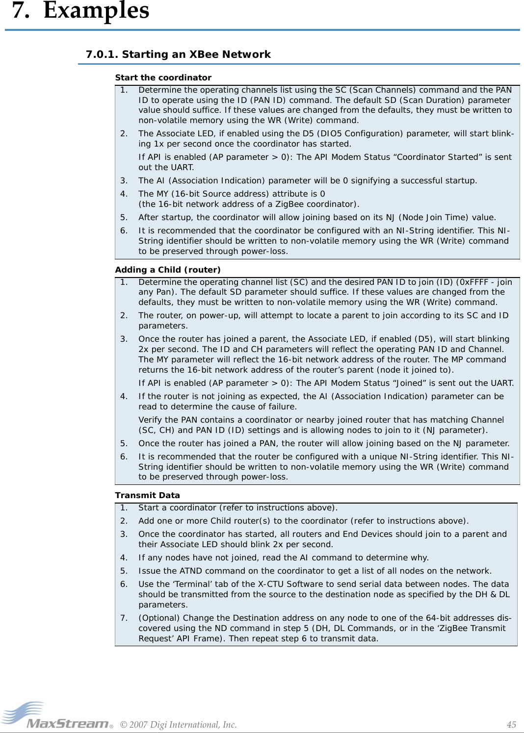
![XBee/XBee‐PROZigBeeOEMRFModulesv1.x1x[2007.06.013]©2007DigiInternational,Inc. 46Chapter7‐Examples7.0.2. AT Command Programming ExamplesSetupSample Configuration: Modify RF Module Destination AddressSample Configuration: Restore RF Module DefaultsThe programming examples in this section require the installation of MaxStream's X-CTU Soft-ware and a serial connection to a PC. (MaxStream stocks RS-232 and USB boards to facilitate interfacing with a PC.)1. Install MaxStream's X-CTU Software to a PC by double-clicking the "setup_X-CTU.exe" file. (The file is located on the MaxStream CD and under the 'Software' section of the following web page: www.maxstream.net/support/downloads.php)2. Mount the RF module to an interface board, then connect the module assembly to a PC.3. Launch the X-CTU Software and select the 'PC Settings' tab. Verify the baud and parity set-tings of the Com Port match those of the RF module.NOTE: Failure to enter AT Command Mode is most commonly due to baud rate mismatch. Ensure the ‘Baud’ setting on the ‘PC Settings’ tab matches the interface data rate of the RF mod-ule. By default, the BD parameter = 3 (which corresponds to 9600 bps).Example: Utilize the X-CTU “Terminal” tab to change the RF module's DL (Destination Address Low) parameter and save the new address to non-volatile memory.After establishing a serial connection between the RF module and a PC [refer to the 'Setup' sec-tion above], select the “Terminal” tab of the X-CTU Software and enter the following command lines (‘CR’ stands for carriage return):Method 1 (One line per command)Send AT Command +++ ATDL <Enter> ATDL1A0D <Enter> ATWR <Enter> ATCN <Enter>System Response OK <CR> (Enter into Command Mode) {current value} <CR> (Read Destination Address Low) OK <CR> (Modify Destination Address Low) OK <CR> (Write to non-volatile memory) OK <CR> (Exit Command Mode)Method 2 (Multiple commands on one line)Send AT Command +++ ATDL <Enter> ATDL1A0D,WR,CN <Enter>System Response OK <CR> (Enter into Command Mode) {current value} <CR> (Read Destination Address Low) OK<CR> OK<CR> OK<CR>Example: Utilize the X-CTU “Modem Configuration” tab to restore default parameter values.After establishing a connection between the module and a PC [refer to the 'Setup' section above], select the “Modem Configuration” tab of the X-CTU Software.1. Select the 'Read' button.2. Select the 'Restore' button.Refertothe‘X‐CTU’sec‐tionoftheDevelop‐mentGuide[AppendixB]formoreinformationregardingtheX‐CTUconfigurationsoftware.](https://usermanual.wiki/MaxStream/XBEE2.USERS-MANUAL/User-Guide-814978-Page-46.png)

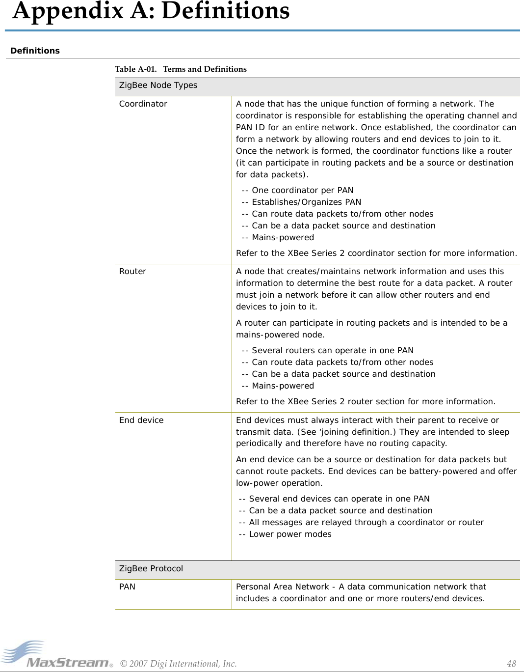
![XBeeSeries2OEMRFModules‐ZigBee‐v1.x1x[2007.06.013]©2007DigiInternational,Inc. 49ChapterA‐DefinitionsJoining The process of a node becoming part of a ZigBee PAN. A node becomes part of a network by joining to a coordinator or a router (that has previously joined to the network). During the process of joining, the node that allowed joining (the parent) assigns a 16-bit address to the joining node (the child).Network Address The 16-bit address assigned to a node after it has joined to another node. The coordinator always has a network address of 0.Operating Channel The frequency selected for data communications between nodes. The operating channel is selected by the coordinator on power-up.Energy Scan A scan of RF channels that detects the amount of energy present on the selected channels. The coordinator uses the energy scan to determine the operating channel.Route Request Broadcast transmission sent by a coordinator or router throughout the network in attempt to establish a route to a destination node.Route Reply Unicast transmission sent back to the originator of the route request. It is initiated by a node when it receives a route request packet and its address matches the Destination Address in the route request packet.Route Discovery The process of establishing a route to a destination node when one does not exist in the Routing Table. It is based on the AODV (Ad-hoc On-demand Distance Vector routing) protocol.ZigBee Stack ZigBee is a published specification set of high-level communication protocols for use with small, low-power modules. The ZigBee stack provides a layer of network functionality on top of the 802.15.4 specification.For example, the mesh and routing capabilities available to ZigBee solutions are absent in the 802.15.4 protocol.TableA‐01. TermsandDefinitions](https://usermanual.wiki/MaxStream/XBEE2.USERS-MANUAL/User-Guide-814978-Page-49.png)
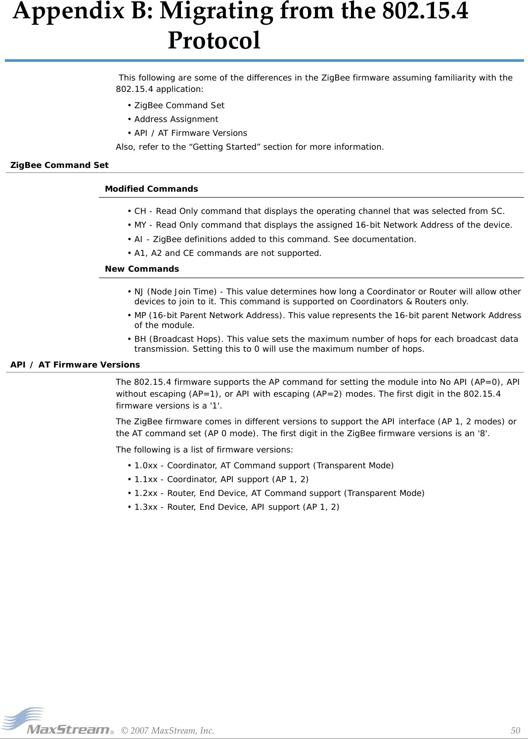
![©2007MaxStream,Inc. 51AppendixC:AgencyCertificationsUnited States FCCThe XBee Series 2 RF Module complies with Part 15 of the FCC rules and regulations. Compliance with the labeling requirements, FCC notices and antenna usage guidelines is required.To fufill FCC Certification, the OEM must comply with the following regulations:OEM Labeling RequirementsWARNING: The Original Equipment Manufacturer (OEM) must ensure that FCC labeling requirements are met. This includes a clearly visible label on the outside of the final product enclosure that displays the contents shown in the figure below.Required FCC Label for OEM products containing the XBee Series 2 RF Module FCC NoticesIMPORTANT: The XBee Series 2 OEM RF Module has been certified by the FCC for use with other products without any further certification (as per FCC section 2.1091). Modifications not expressly approved by MaxStream could void the user's authority to operate the equipment.IMPORTANT: OEMs must test final product to comply with unintentional radiators (FCC section 15.107 & 15.109) before declaring compliance of their final product to Part 15 of the FCC Rules.IMPORTANT: The RF module has been certified for remote and base radio applications. If the module will be used for portable applications, the device must undergo SAR testing.This equipment has been tested and found to comply with the limits for a Class B digital device, pursuant to Part 15 of the FCC Rules. These limits are designed to provide reasonable protection against harmful interference in a residential installation. This equipment generates, uses and can radiate radio frequency energy and, if not installed and used in accordance with the instructions, may cause harmful interference to radio communications. However, there is no guarantee that interference will not occur in a particular installation. If this equipment does cause harmful interference to radio or television reception, which can be determined by turning the equipment off and on, the user is encouraged to try to correct the interference by one or more of the following measures: Re-orient or relocate the receiving antenna, Increase the separation between the equipment and receiver, Connect equipment and receiver to outlets on different circuits, or Consult the dealer or an experienced radio/TV technician for help.FCC-Approved Antennas (2.4 GHz)The XBee Series 2 RF Module can be installed utilizing antennas and cables constructed with standard connectors (Type-N, SMA, TNC, etc.) if the installation is performed professionally and according to FCC guidelines. For installations not performed by a professional, non-standard connectors (RPSMA, RPTNC, etc.) must be used.The modules are FCC approved for fixed base station and mobile applications on channels 0x0B - 0x1A. If the antenna is mounted at least 20cm (8 in.) from nearby persons, the application is considered a mobile application. Antennas not listed in the table must be tested to comply with FCC Section 15.203 (Unique Antenna Connectors) and Section 15.247 (Emissions).1. The system integrator must ensure that the text on the external label provided with this device is placed on the outside of the final product. [Figure A-01] 2. XBee Series 2 RF Module may only be used with antennas that have been tested and approved for use with this module [refer to the antenna tables in this section].Contains FCC ID: OUR-XBEE2*The enclosed device complies with Part 15 of the FCC Rules. Operation is subject to the following two conditions: (i.) this device may not cause harmful interference and (ii.) this device must accept any interference received, including interference that may cause undesired operation.](https://usermanual.wiki/MaxStream/XBEE2.USERS-MANUAL/User-Guide-814978-Page-51.png)
![XbeeSeries2ZigBeeOEMRFModulesv1.x1x[2007.06.013]©2007MaxStream,Inc. 52AgencyCertificationsXBee Series 2 RF Modules: XBee Series 2 RF Modules have been tested and approved for use with all the antennas listed in the tables below. (Cable-loss IS required when using gain antennas as shown below.)TableA‐01. antennasapprovedforusewiththeXBeeSeries2RFModules* If using the RF module in a portable application (For example - If the module is used in a handheld device and the antenna is less than 20cm from the human body when the device is in operation): The integrator is responsible for passing additional SAR (Specific Absorption Rate) testing based on FCC rules 2.1091 and FCC Guidelines for Human Exposure to Radio Frequency Electromagnetic Fields, OET Bulletin and Supplement C. The testing results will be submitted to the FCC for approval prior to selling the integrated unit. The required SAR testing measures emissions from the module and how they affect the person.RF ExposureWARNING: To satisfy FCC RF exposure requirements for mobile transmitting devices, a separation distance of 20 cm or more should be maintained between the antenna of this device and persons during device operation. To ensure compliance, operations at closer than this distance are not recommended. The antenna used for this transmitter must not be co-located in conjunction with any other antenna or transmitter.The preceding statement must be included as a CAUTION statement in OEM product manuals in order to alert users of FCC RF Exposure compliance.Europe (ETSI)The XBee Series 2 RF Module has been certified for use in several European countries. For a complete list, refer to www.maxstream.net.If the XBee Series 2 RF Modules are incorporated into a product, the manufacturer must ensure compliance of the final product to the European harmonized EMC and low-voltage/safety YAGI CLASS ANTENNASPart Number Type (Description) Gain Application* Min. Separation Required Cable-lossA24-Y6NF Yagi (6-element) 8.8 dBi Fixed 2 m 7.8dBA24-Y7NF Yagi (7-element) 9.0 dBi Fixed 2 m 8 dBA24-Y9NF Yagi (9-element) 10.0 dBi Fixed 2 m 9 dBA24-Y10NF Yagi (10-element) 11.0 dBi Fixed 2 m 10 dBA24-Y12NF Yagi (12-element) 12.0 dBi Fixed 2 m 11 dBA24-Y13NF Yagi (13-element) 12.0 dBi Fixed 2 m 11 dBA24-Y15NF Yagi (15-element) 12.5 dBi Fixed 2 m 11.5 dBA24-Y16NF Yagi (16-element) 13.5 dBi Fixed 2 m 12.5 dBA24-Y16RM Yagi (16-element, RPSMA connector) 13.5 dBi Fixed 2 m 12.5 dBA24-Y18NF Yagi (18-element) 15.0 dBi Fixed 2 m 14 dBOMNI-DIRECTIONAL ANTENNASPart Number Type (Description) Gain Application* Min. Separation Required Cable-lossA24-C1 Surface Mount integral chip 1.5 dBi Fixed/Mobile 20 cm -A24-F2NF Omni-directional (Fiberglass base station) 2.1 dBi Fixed/Mobile 20 cm -A24-F3NF Omni-directional (Fiberglass base station) 3.0 dBi Fixed/Mobile 20 cm .3 dBA24-F5NF Omni-directional (Fiberglass base station) 5.0 dBi Fixed/Mobile 20 cm 2.3 dBA24-F8NF Omni-directional (Fiberglass base station) 8.0 dBi Fixed 2 m 5.3 dBA24-F9NF Omni-directional (Fiberglass base station) 9.5 dBi Fixed 2 m 6.8 dBA24-F10NF Omni-directional (Fiberglass base station) 10.0 dBi Fixed 2 m 7.3 dBA24-F12NF Omni-directional (Fiberglass base station) 12.0 dBi Fixed 2 m 9.3dBA24-F15NF Omni-directional (Fiberglass base station) 15.0 dBi Fixed 2 m 12.3dBA24-W7NF Omni-directional (Base station) 7.2 dBi Fixed 2 m 4.5 dBA24-M7NF Omni-directional (Mag-mount base station) 7.2 dBi Fixed 2 m 4.5 dBPANEL CLASS ANTENNASPart Number Type (Description) Gain Application* Min. Separation Required Cable-lossA24-P8SF Flat Panel 8.5 dBi Fixed 2 m 8.2 dBA24-P8NF Flat Panel 8.5 dBi Fixed 2 m 82 dBA24-P13NF Flat Panel 13.0 dBi Fixed 2 m 12.7 dBA24-P14NF Flat Panel 14.0 dBi Fixed 2 m 13.7 dBA24-P15NF Flat Panel 15.0 dBi Fixed 2 m 14.7 dBA24-P16NF Flat Panel 16.0 dBi Fixed 2 m 15.7 dBA24-P19NF Flat Panel 19.0 dBi Fixed 2m 18.7 dB](https://usermanual.wiki/MaxStream/XBEE2.USERS-MANUAL/User-Guide-814978-Page-52.png)
![XbeeSeries2ZigBeeOEMRFModulesv1.x1x[2007.06.013]©2007MaxStream,Inc. 53AgencyCertificationsstandards. A Declaration of Conformity must be issued for each of these standards and kept on file as described in Annex II of the R&TTE Directive. Furthermore, the manufacturer must maintain a copy of the XBee Series 2 user manual documentation and ensure the final product does not exceed the specified power ratings, antenna specifications, and/or installation requirements as specified in the user manual. If any of these specifications are exceeded in the final product, a submission must be made to a notified body for compliance testing to all required standards.OEM Labeling RequirementsThe 'CE' marking must be affixed to a visible location on the OEM product.FigureC‐01. CELabelingRequirementsThe CE mark shall consist of the initials "CE" taking the following form:• If the CE marking is reduced or enlarged, the proportions given in the above graduated draw-ing must be respected.• The CE marking must have a height of at least 5mm except where this is not possible on account of the nature of the apparatus.• The CE marking must be affixed visibly, legibly, and indelibly.RestrictionsPower Output: The power output of the XBee Series 2 RF Module must not exceed 10 dBm. The power level is set using the PL command and the PL parameter must equal “0” (10 dBm).France: France imposes restrictions on the 2.4 GHz band. Go to www.art-telecom.Fr or contact MaxStream for more information.Norway: Norway prohibits operation near Ny-Alesund in Svalbard. More information can be found at the Norway Posts and Telecommunications site (www.npt.no).Declarations of ConformityMaxStream has issued Declarations of Conformity for the XBee Series 2 RF Modules concerning emissions, EMC and safety. Files are located in the 'documentation' folder of the MaxStream CD.Important NoteMaxStream does not list the entire set of standards that must be met for each country. MaxStream customers assume full responsibility for learning and meeting the required guidelines for each country in their distribution market. For more information relating to European compliance of an OEM product incorporating the XBee Series 2 RF Module, contact MaxStream, or refer to the following web sites:CEPT ERC 70-03E - Technical Requirements, European restrictions and general requirements: Available at www.ero.dk/.R&TTE Directive - Equipment requirements, placement on market: Available at www.ero.dk/.Approved AntennasWhen integrating high-gain antennas, European regulations stipulate EIRP power maximums. Use the following guidelines to determine which antennas to design into an application.XBee Series 2 OEM ModuleThe following antennas types have been tested and approved for use with the XBee Series 2 Module:](https://usermanual.wiki/MaxStream/XBEE2.USERS-MANUAL/User-Guide-814978-Page-53.png)
![XbeeSeries2ZigBeeOEMRFModulesv1.x1x[2007.06.013]©2007MaxStream,Inc. 54AgencyCertificationsAntenna Type: YagiRF module was tested and approved with 15 dBi antenna gain with 1 dB cable-loss (EIRP Maimum of 14 dBm). Any Yagi type antenna with 14 dBi gain or less can be used with no cable-loss.Antenna Type: Omni-DirectionalRF module was tested and approved with 15 dBi antenna gain with 1 dB cable-loss (EIRP Maimum of 14 dBm). Any Omni-Directional type antenna with 14 dBi gain or less can be used with no cable-loss.Antenna Type: Flat PanelRF module was tested and approved with 19 dBi antenna gain with 4.8 dB cable-loss (EIRP Maimum of 14.2 dBm). Any Flat Panel type antenna with 14.2 dBi gain or less can be used with no cable-loss.XBee Series 2 RF ModuleThe following antennas have been tested and approved for use with the embedded XBee Series 2 RF Module:- Dipole (2.1 dBi, Omni-directional, Articulated RPSMA, MaxStream part number A24-HABSM)- Chip Antenna (-1.5 dBi)- Attached Monopole Whip (1.5 dBi)Canada (IC)Labeling RequirementsLabeling requirements for Industry Canada are similar to those of the FCC. A clearly visible label on the outside of the final product enclosure must display the following text:Contains Model XBee Series 2 Radio, IC: 4214A-XBEE2The integrator is responsible for its product to comply with IC ICES-003 & FCC Part 15, Sub. B - Unintentional Radiators. ICES-003 is the same as FCC Part 15 Sub. B and Industry Canada accepts FCC test report or CISPR 22 test report for compliance with ICES-003.](https://usermanual.wiki/MaxStream/XBEE2.USERS-MANUAL/User-Guide-814978-Page-54.png)
![©2007DigiInternational,Inc. 55AppendixD:DevelopmentGuideXBee Series 2 Development KitsThe XBee Series 2 Professional Development Kit includes the hardware and software needed to rapidly create long range wireless data links between nodes (XBee Series 2 Starter Kits that contain fewer modules and accessories are also available).Interfacing OptionsThe development kit includes RS-232 and USB interface boards. The boards provide a connection to PC ports and therefore give access to the RF module registries. Parameters stored in the registry allow OEMs and integrators to customize the modules to suite the needs of their data radio systems.The following sections illustrate how to use the interface boards for development purposes. The MaxStream Interface board provides means for connecting the module to any node that has an available RS-232 or USB connector. Since the module requires signals to enter at TTL voltages, one of the main functions of the interface board is to convert signals between TTL levels and RS-232 and USB levels.TableD‐01. ItemsIncludedintheDevelopmentKitItem Qty. Description Part #XBee Series 2 Module 5(1) OEM RF Module, AT Coordinator with wire antenna (1) OEM RF Module, AT Router/End Device with wire antenna(1) OEM RF Module, AT Router/End Device with U.FL antenna(1) OEM RF Module, AT Router/End Device with chip antenna(1) OEM RF Module, AT Router/End Device with SMA antennaXB24-BWIt-002XB24-BWIT-004XB24-BUIT-004XB24-BCIT-004XB24-BSIT-004RS-232 Development Board 4 Board for interfacing between modules and RS-232 nodes(Converts signal levels, displays diagnostic info, & more) XBIB-RUSB Development Board 1 Board for interfacing between modules & USB nodes(Converts signal levels, displays diagnostic info, & more) XBIB-URS-232 Cable (6’, straight-through) 1Cable for connecting RS-232 interface board with DTE nodes(nodes that have a male serial DB-9 port - such as most PCs) JD2D3-CDS-6FUSB Cable (6’) 1 Cable for connecting USB interface board to USB nodes JU1U2-CSB-6FSerial Loopback Adapter 1[Red] Adapter for configuring the module assembly (module + RS-232interface board) to function as a repeater for range testing JD2D3-CDL-ANULL Modem Adapter (male-to-male) 1[Black] Adapter for connecting the module assembly (module + RS-232interface board) to other DCE (female DB-9) nodes JD2D2-CDN-ANULL Modem Adapter (female-to-female) 1[Gray] Adapter for connecting serial nodes. It allows users to bypass the radios to verify serial cabling is functioning properly. JD3D3-CDN-APower Adapter (9VDC, 1 A) 1 Adapter for powering the RS-232 development board JP5P2-9V11-6FBattery Clip (9V) 1 Clip for remotely powering the RS-232 board w/ a 9V battery JP2P3-C2C-4IRPSMA Antenna 2 RPSMA half-wave dipole antenna (2.4 GHz, 2.1 dB) A24-HASM-450RF Cable Assembly 2 Adapter for connecting RPSMA antenna to U.FL connector JF1R6-CR3-4ICD 1 Documentation and Software MD0030Quick Start Guide 1 Step-by-step instruction on how to create wireless links & test range capabilities of the modules MD0026](https://usermanual.wiki/MaxStream/XBEE2.USERS-MANUAL/User-Guide-814978-Page-55.png)
![XBee/XBee‐PROZigBeeOEMRFModulesv1.x1x[2007.06.013]©2007DigiInternational,Inc. 56DevelopmentGuideNote: In the following sections, an OEM RF Module mounted to an interface board will be referred to as a "Module Assembly".RS-232 Development BoardExternal Interface B-01a. Reset SwitchFigureB‐01. FrontView The Reset Switch is used to reset (re-boot) the RF module. This switch only applies when using the configuration tabs of MaxStream’s X-CTU Software. B-01b. I/O & Power LEDsLEDs indicate RF module activity as follows:Yellow (top LED) = Serial Data Out (to host)Green (middle) = Serial Data In (from host)Red (bottom) = Power/Association Indicator (Refer to the D5 (DIO5 Configuration) parameter) B-01c. Serial PortStandard female DB-9 (RS-232) connector. B-01d. RSSI LEDsRSSI LEDs indicate the amount of fade margin present in an active wireless link. Fade margin is defined as the difference between the incoming signal strength and the module's receiver sensitivity.3 LEDs ON = Very Strong Signal (> 30 dB fade margin)2 LEDs ON = Strong Signal (> 20 dB fade margin)1 LED ON = Moderate Signal (> 10 dB fade margin)0 LED ON = Weak Signal (< 10 dB fade margin) B-01e. Power Connector5-14 VDC power connector B-02a. DIP SwitchFigureB‐02. BackView DIP Switch functions are not supported in this release. Future down-loadable firmware versions will support DIP Switch configurations.B‐01a.ConfigSwitchB‐01b.I/O&PowerLEDsB‐01c.DB‐9SerialPortB‐01dRSSILEDsB‐01e.PowerConnectorB‐02a.DIPSwitch](https://usermanual.wiki/MaxStream/XBEE2.USERS-MANUAL/User-Guide-814978-Page-56.png)
![XBee/XBee‐PROZigBeeOEMRFModulesv1.x1x[2007.06.013]©2007DigiInternational,Inc. 57DevelopmentGuideRS-232 Pin SignalsFigureB‐03. PinsusedonthefemaleRS‐232(DB‐9)SerialConnector*Functionslistedintheimplementationcolumnmaynotbeavailableatthetimeofrelease.TableD‐02. PinAssignmentsandImplementationsDB-9 Pin RS-232 Name Description Implementation*1 DCD Data-Carrier-Detect Connected to DSR (pin6)2 RXD Receive Data Serial data exiting the module assembly (to host)3 TXD Transmit Data Serial data entering into the module assembly (from host)4 DTR Data-Terminal-Ready Can enable Power-Down on the module assembly5 GND Ground Signal Ground6 DSR Data-Set-Ready Connected to DCD (pin1)7RTS / CMD Request-to-Send / Command ModeProvides RTS flow control orenables Command Mode8CTS Clear-to-Send Provides CTS flow control9 RI Ring Indicator Optional power input that is connected internally to the positive lead of the front power connector](https://usermanual.wiki/MaxStream/XBEE2.USERS-MANUAL/User-Guide-814978-Page-57.png)
![XBee/XBee‐PROZigBeeOEMRFModulesv1.x1x[2007.06.013]©2007DigiInternational,Inc. 58DevelopmentGuideWiring DiagramsFigureB‐04. DTEnode(RS‐232,maleDB‐9connector)wiredtoaDCEModuleAssembly(femaleDB‐9)FigureB‐05. DCEModuleAssembly(femaleDB‐9connector)wiredtoaDCEnode(RS‐232,maleDB‐9) Sample Wireless Connection: DTE <--> DCE <--> DCE <--> DCEFigureB‐06. TypicalwirelesslinkbetweenDTEandDCEnodes](https://usermanual.wiki/MaxStream/XBEE2.USERS-MANUAL/User-Guide-814978-Page-58.png)
![XBee/XBee‐PROZigBeeOEMRFModulesv1.x1x[2007.06.013]©2007DigiInternational,Inc. 59DevelopmentGuideAdaptersThe development kit includes several adapters that support the following functions:• Performing Range Tests• Testing Cables• Connecting to other RS-232 DCE and DTE nodes• Connecting to terminal blocks or RJ-45 (for RS-485/422 nodes)NULL Modem Adapter (male-to-male)Part Number: JD2D2-CDN-A (Black, DB-9 M-M) The male-to-male NULL modem adapter is used to connect two DCE nodes. A DCE node connects with a straight-through cable to the male serial port of a computer (DTE).FigureB‐07. MaleNULLmodemadapterandpinoutsFigureB‐08. ExampleofaMaxStreamRadioModem(DCEnode)connectingtoanotherDCEnode)NULL Modem Adapter (female-to-female)Part Number: JD3D3-CDN-A (Gray, DB-9 F-F) The female-to-female NULL modem adapter is used to verify serial cabling is functioning properly. To test cables, insert the female-to-female NULL modem adapter in place of a pair of module assemblies (RS-232 interface board + XTend Module) and test the connection without the modules in the connection.FigureB‐09. FemaleNULLmodemadapterandpinoutsSerial Loopback AdapterPart Number: JD2D3-CDL-A (Red, DB-9 M-F) The serial loopback adapter is used for range testing. During a range test, the serial loopback adapter configures the module to function as a repeater by looping serial data back into the radio for retransmission.FigureD‐01. Serialloopbackadapterandpinouts](https://usermanual.wiki/MaxStream/XBEE2.USERS-MANUAL/User-Guide-814978-Page-59.png)
![XBee/XBee‐PROZigBeeOEMRFModulesv1.x1x[2007.06.013]©2007DigiInternational,Inc. 60DevelopmentGuideUSB Development BoardExternal Interface B-11a. I/O & Power LEDsFigureD‐02. FrontView LEDs indicate RF module activity as follows:Yellow (top LED) = Serial Data Out (to host)Green (middle) = Serial Data In (from host)Red (bottom) = Power/Association Indicator (Refer to the D5 (DIO5 Configuration) parameter) B-11b. RSSI LEDsRSSI LEDs indicate the amount of fade margin present in an active wireless link. Fade margin is defined as the difference between the incoming signal strength and the module's receiver sensitivity.3 LEDs ON = Very Strong Signal (> 30 dB fade margin)2 LEDs ON = Strong Signal (> 20 dB fade margin)1 LED ON = Moderate Signal (> 10 dB fade margin)0 LED ON = Weak Signal (< 10 dB fade margin) B-11c. USB PortStandard Type-B OEM connector is used to communicate with OEM host and power the RF module. B-12a. DIP SwitchFigureD‐03. BackView DIP Switch functions are not supported in this release. Future down-loadable firmware versions will support the DIP Switch configurations. B-12b. Reset SwitchThe Reset Switch is used to reset (re-boot) the RF module.B‐11a.I/O&PowerLEDsB‐11b.RSSILEDsB‐11c.USBPortB‐12a.DIPSwitchB‐12a.ResetSwitch](https://usermanual.wiki/MaxStream/XBEE2.USERS-MANUAL/User-Guide-814978-Page-60.png)
![XBee/XBee‐PROZigBeeOEMRFModulesv1.x1x[2007.06.013]©2007DigiInternational,Inc. 61DevelopmentGuideUSB Pin SignalsX-CTU SoftwareX-CTU is a MaxStream-provided software program used to interface with and configure MaxStream RF Modules. The software application is organized into the following four tabs:• PC Settings tab - Setup PC serial ports for interfacing with an RF module• Range Test tab - Test the RF module's range and monitor packets sent and received• Terminal tab - Set and read RF module parameters using AT Commands• Modem Configuration tab - Set and read RF module parametersFigureD‐04. X‐CTUUserInterface(PCSettings,RangeTest,TerminalandModemConfigurationtabs)NOTE: PC Setting values are visible at the bottom of the Range Test, Terminal and Modem Configura-tion tabs. A shortcut for editing PC Setting values is available by clicking on any of the values.InstallDouble-click the "setup_X-CTU.exe" file and follow prompts of the installation screens. This file is located in the 'software' folder of the MaxStream CD and also under the 'Downloads' section of the following web page: www.maxstream.net/support/downloads.phpSetupSerial Communications SoftwareA terminal program is built into the X-CTU Software. Other terminal programs such as "HyperTerminal" can also be used. When issuing AT Commands through a terminal program interface, use the following syntax:FigureD‐05. SyntaxforsendingATCommandsTableD‐03. USBsignalsandtheirimplantationsontheXBee/XBee‐PRORFModulePin Name Description Implementation1 VBUS Power Power the RF module2 D- Transmitted & Received Data Transmit data to and from the RF module3 D+ Transmitted & Received Data Transmit data to and from the RF module4 GND Ground Signal GroundTo use the X-CTU software, a module assembly (An RF module mounted to an interface Board) must be connected to a serial port of a PC. The interface data rate and parity settings of the serial port ("PC Settings" tab) must match those of the module (BD (Baud Rate) and NB (Parity) parameters).](https://usermanual.wiki/MaxStream/XBEE2.USERS-MANUAL/User-Guide-814978-Page-61.png)
![XBee/XBee‐PROZigBeeOEMRFModulesv1.x1x[2007.06.013]©2007DigiInternational,Inc. 62DevelopmentGuideNOTE: To read a parameter value stored in a register, leave the parameter field blank.The example above issues the DL (Destination Address Low) command to change destination address of the module to "0x1F". To save the new value to the module’s non-volatile memory, issue WR (Write) command after modifying parameters.](https://usermanual.wiki/MaxStream/XBEE2.USERS-MANUAL/User-Guide-814978-Page-62.png)
![©2007DigiInternational,Inc. 63AppendixE:AdditionalInformation1-Year WarrantyXBee Series 2 RF Modules from MaxStream, Inc. (the "Product") are warranted against defects in materials and workmanship under normal use, for a period of 1-year from the date of purchase. In the event of a product failure due to materials or workmanship, MaxStream will repair or replace the defective product. For warranty service, return the defective product to MaxStream, shipping prepaid, for prompt repair or replacement.The foregoing sets forth the full extent of MaxStream's warranties regarding the Product. Repair or replacement at MaxStream's option is the exclusive remedy. THIS WARRANTY IS GIVEN IN LIEU OF ALL OTHER WARRANTIES, EXPRESS OR IMPLIED, AND MAXSTREAM SPECIFICALLY DISCLAIMS ALL WARRANTIES OF MERCHANTABILITY OR FITNESS FOR A PARTICULAR PURPOSE. IN NO EVENT SHALL MAXSTREAM, ITS SUPPLIERS OR LICENSORS BE LIABLE FOR DAMAGES IN EXCESS OF THE PURCHASE PRICE OF THE PRODUCT, FOR ANY LOSS OF USE, LOSS OF TIME, INCONVENIENCE, COMMERCIAL LOSS, LOST PROFITS OR SAVINGS, OR OTHER INCIDENTAL, SPECIAL OR CONSE-QUENTIAL DAMAGES ARISING OUT OF THE USE OR INABILITY TO USE THE PRODUCT, TO THE FULL EXTENT SUCH MAY BE DISCLAIMED BY LAW. SOME STATES DO NOT ALLOW THE EXCLUSION OR LIMITATION OF INCIDENTAL OR CONSEQUENTIAL DAMAGES. THEREFORE, THE FOREGOING EXCLUSIONS MAY NOT APPLY IN ALL CASES. This warranty provides specific legal rights. Other rights which vary from state to state may also apply.Ordering InformationFigureE‐01.DivisionsoftheXBee/XBee‐PRORFModulePartNumbersContact MaxStreamFree and unlimited technical support is included with every MaxStream Radio Modem sold. For the best in wireless data solutions and support, please use the following resources:MaxStream office hours are 8:00 am - 5:00 pm [U.S. Mountain Standard Time]Documentation: www.maxstream.net/support/downloads.phpTechnical Support: Phone. (866) 765-9885 toll-free U.S.A. & Canada (801) 765-9885 WorldwideLive Chat. www.maxstream.net E-Mail. rf-xperts@maxstream.net X B 2 4 -B I T -0 0Antenna Types S = RPSMAW = Wire AntennaC = Chip AntennaU = U.FL ConnectorFirmware versions1 = Coordinator; API Operation2 = Coordinator; Transparent Operation3 = Router/End Device; API Operation4 = Router/End Device, Transparent Operation](https://usermanual.wiki/MaxStream/XBEE2.USERS-MANUAL/User-Guide-814978-Page-63.png)