Maxell ME-M23 ME-MR23 User Manual
Hitachi Maxell, Ltd. ME-MR23
UserManual.wiki
>
Maxell
>
ME M23 User Manual
Users Manual
Navigation menu
Upload a User Manual
Namespaces
Wiki Guide
HTML
PDF
Info
Views
User Manual
Discussion / Help
Navigation
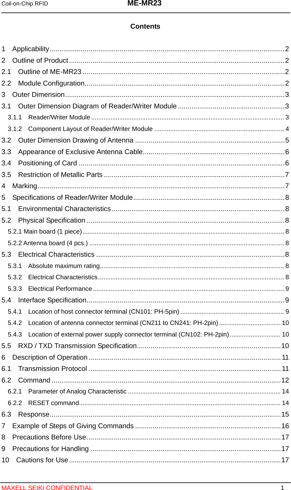
![Coil-on-Chip RFID ME-MR23 MAXELL SEIKI CONFIDENTIAL 11 6 Description of Operation 6.1 Transmission Protocol Image of transmission protocol between host computer, Reader/Writer Module, and RFID chip is shown in Figure 6-1. Reader/Writer Module receives command and data from the host computer and transmits them to RFID chip. It also receives response and data from RFID chip, and judges whether transmission is completed or not, and then transmits the results to the host computer, Fig. 6-1 Image of Transmission Protocol ※3 Keep the time shown in Table B as timeout own time at minimum (take margins into consideration for design). Command Frame configuration Byte numberTimeout time [ms] Command Timeout time[ms]COUNT COUNT+CT_NUM REQ 120 CHANGE CHANGE+BAUDRATE 2 5.0 SEL 45 TEST+TEST_CODE READ 80 TEST TEST+RF_OFF 3 8.8 WRITE 100 WRITE WRITE+DATA WRITE_NOP 40 WRITE_NOP WRITE_NOP+DATA WRITE_ST 100 WRITE_ST WRITE_ST+DATA HALT 40 HALT HALT+UID 5 15.3 COUNT 60 SEL SEL+UID+KEY 9 28.6 TEST 5 TEST(RF_OFF) 5 RESET 5 Transmission of command/ dataCommand processed, response processed Receipt of response/ dataReader/Writer module RFID chip B: Monitoring (timeout judgment)※3 Response processed Issue of command Host A ・ Because reader/writer module is not set for timer between characters, complete transmission of designated byte rate within the timeout time indicated in Table A. ・ Take an interval of more than 5ms between completion of receipt of response and start of next command transmission,Table A: List of receiving timeout times of multiple bytescommand Table B. List of theoretical timeout values fromtransmission of command to receipt of response](https://usermanual.wiki/Maxell/ME-M23/User-Guide-1162681-Page-12.png)
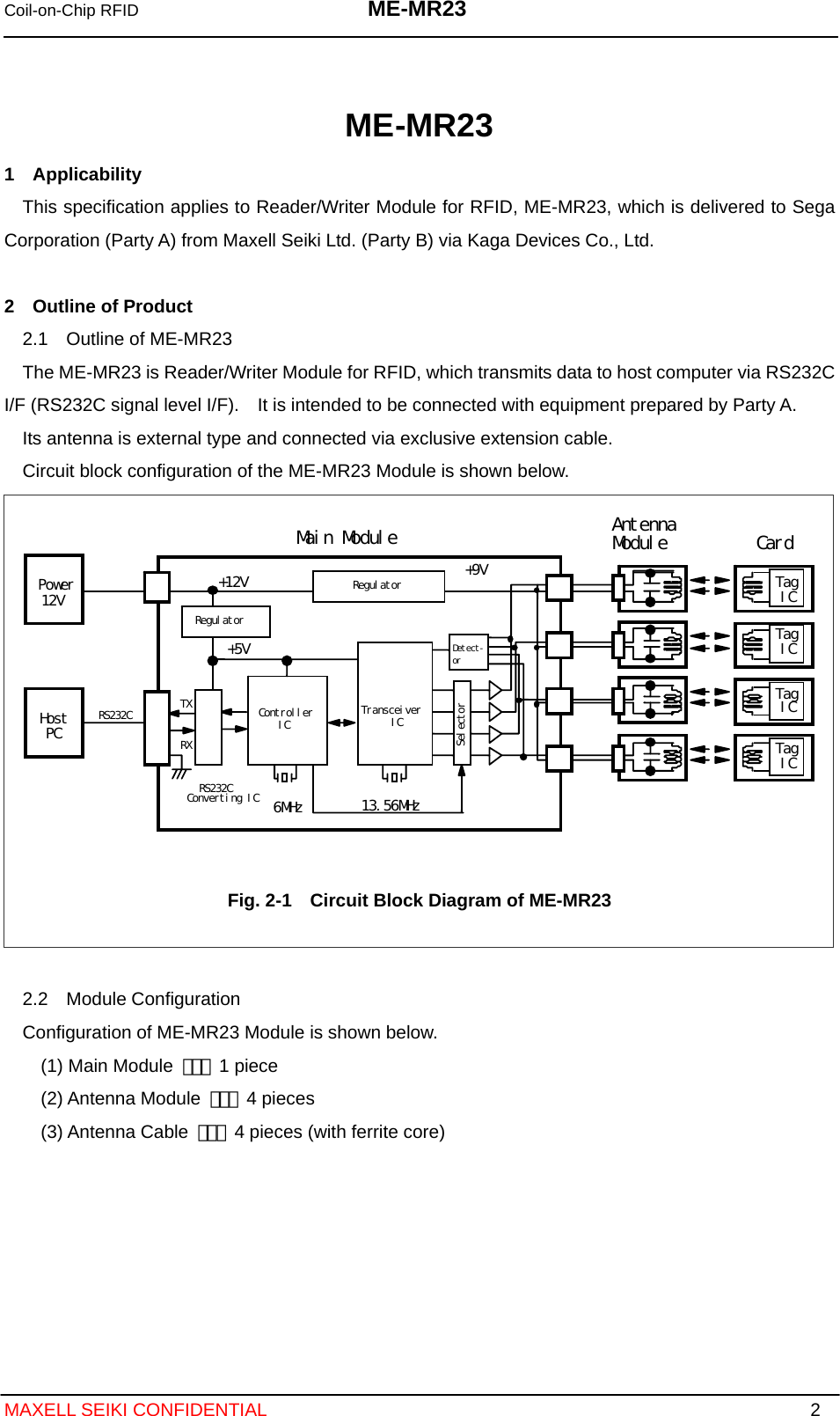
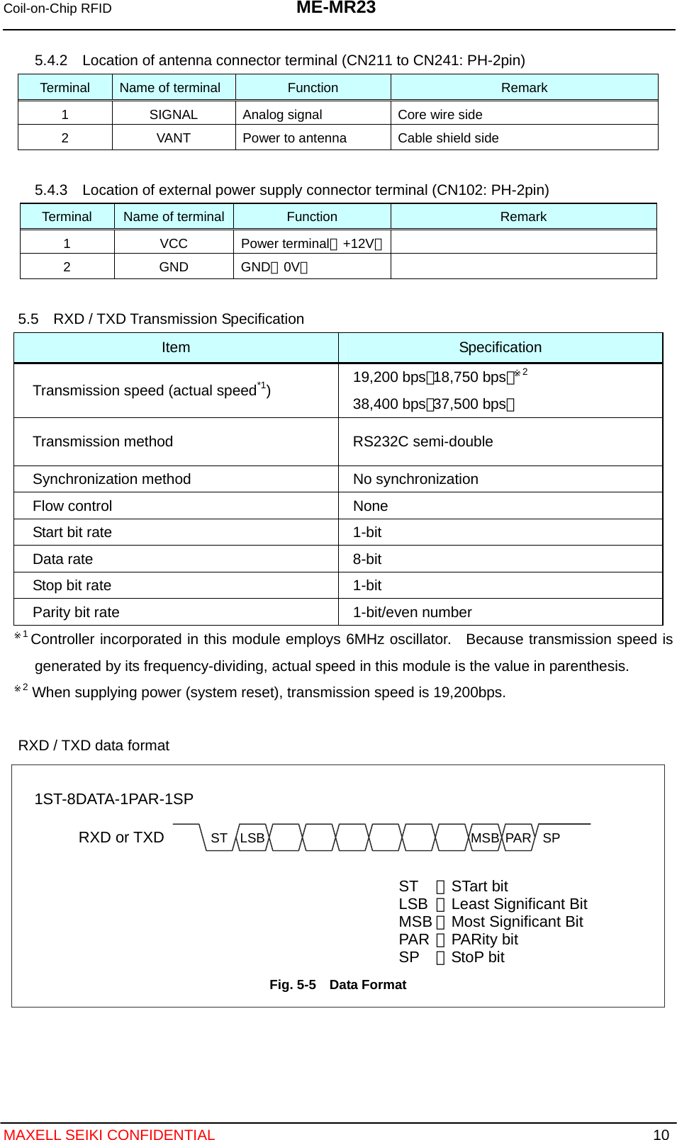
![Coil-on-Chip RFID ME-MR23 MAXELL SEIKI CONFIDENTIAL 13 Command to Reader/Writer Module Command Code[Hex] Description of Functions REQ 4E Requesting communication with RFID chip. However in case of REQ command with carrier OFF, no response from RFID chip, because it serves as a command requesting carrier ON (transfer to operation status). SEL 2E Selecting a specific RFID chip. UID Existing (4-byte) Unique ID of RFID chip. It is already written at factory and cannot be changed. KEY Random (4-byte) Key of RFID chip (code). Checking KEY against SEL command, and executing access restriction depending on match or mismatch. READ 0E Reading memory of RFID chip (128-byte collectively) WRITE CE Increasing write pointer of RFID chip with an increment (+1) and write to memory (4-byte unit). DATA Random (4-byte) Data to be written. It may be invalid depending on access restriction, but 4-byte data is requiredWRITE_NOP 8E Increasing write pointer of RFID chip with increment (+1). Actual writing is not executed. But dummy data (4-byte) at transmission of command is required. WRITE_ST EE Returning write pointer of memory to zero (position of Serial No.0). Writing to RFID chip is not executed. But data at transmission of command (4-byte, dummy) is required. HALT AE Halting a specific RFID chip. COUNT 6E Decreasing down counter of RFID chip with decrement (-1). 03 0C 30 CT_NUM C0 Specifying counter for decrement. Select one CT_NUM code corresponding any of Counter 1 to 4. Counter1: 03h, Counter2: 0Ch, Counter3: 30h, Counter4: C0h RESET 7E Initializing controller. TEST 5E Setting parameters of analog characteristics of transceiver/antenna selection. Transmission of carrier from module is checked by TEST command (TEST_CODE:00**). If the response is NOT (6Ah), the carrier is not transmitted. F0** (2Byte) Parameter of antenna selection. Shifting antenna to be activated with lower 1-byte (** mentioned on the left).01h: select antenna to be connected with CN211 02h: select antenna to be connected with CN221 03h: select antenna to be connected with CN231 04h: select antenna to be connected with CN241 TEST_CODE 00** (2Byte) Parameter of receiving gain characteristic of transceiver. Shifting receiving gain with lower 1-byte (** mentioned on the left). RF_OFF 80** (2Byte) Stopping carrier by TEST+RF_OFF Lower 1-byte (** mentioned on the left) is at random.](https://usermanual.wiki/Maxell/ME-M23/User-Guide-1162681-Page-14.png)
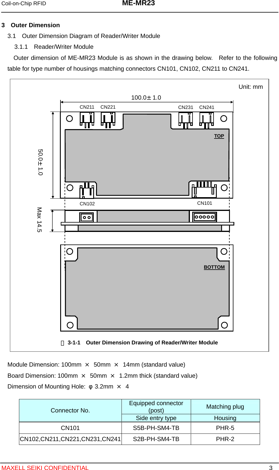
![Coil-on-Chip RFID ME-MR23 MAXELL SEIKI CONFIDENTIAL 15 6.3 Response Responses returned from Reader/Writer Module to host computer are shown below. bit7 1B LSB 【RC1】 OK bit7 1B LSB 【RC2】 RETRY bit7 1B LSB 【RC3】 NG bit7 1B LSB 4B● 【RC4】 OK UID bit7 1B LSB 128B● 【RC5】 OK DATA bit7 1B LSB bit7 1B LSB【RC6】 OK VALUE bit7 1B LSB 【RC7】 NOT B : Byte ● When processing multiple byte data (ex. UID, TEST_CODE) for data transmission, take the following steps. “Transmit upstream byte by LSB First. → Transmit next byte by LSB First. MSB with the lowest byte is the last transmission.” Response to Host Computer Response Code[Hex] Description of Function OK 0A Response in case transmission is successful. Response is given when any of ATQ, ATQ_C, and ACK is received without transmission error or in case of processing command by controller. RETRY CA Response requesting retry to send command when transmission error occurs. NG 3A Response in case /DETECT of Reader/Writer Module equals to 1. In case of /DETECT = 1, the Reader/Writer Module decides there is no RFID to communicate with and does not communicate with RFID chip. UID Prearranged (4-byte) Unique ID of RFID chip. DATA Random (128-byte) Data of RFID chip. If condition of access to memory is set in advance, the data is that after masking (the masking part is “0”). VALUE Random (1-byte) Counter value after decrease of down counter of RFID chip with decrement (-1). NOT 6A Response in case carrier is not transmitted from the module when giving TEST command (TEST_CODE:00**). Transmission of carrier from the module is checked by TEST command.](https://usermanual.wiki/Maxell/ME-M23/User-Guide-1162681-Page-16.png)