Users Manual

Reader/Writer Module
for
Coil-on-Chip RFID System
ME-MR23(RS232C I/F)
Issued on October 2008
Maxell Seiki, Ltd.

Coil-on-Chip RFID ME-MR23
MAXELL SEIKI CONFIDENTIAL 1
Contents
1 Applicability.........................................................................................................................2
2 Outline of Product...............................................................................................................2
2.1 Outline of ME-MR23 ........................................................................................................2
2.2 Module Configuration.......................................................................................................2
3 Outer Dimension.................................................................................................................3
3.1 Outer Dimension Diagram of Reader/Writer Module.......................................................3
3.1.1 Reader/Writer Module.............................................................................................................. 3
3.1.2 Component Layout of Reader/Writer Module .......................................................................... 4
3.2 Outer Dimension Drawing of Antenna .............................................................................5
3.3 Appearance of Exclusive Antenna Cable.........................................................................6
3.4 Positioning of Card ..........................................................................................................6
3.5 Restriction of Metallic Parts .............................................................................................7
4 Marking...............................................................................................................................7
5 Specifications of Reader/Writer Module..............................................................................8
5.1 Environmental Characteristics.........................................................................................8
5.2 Physical Specification ......................................................................................................8
5.2.1 Main board (1 piece)................................................................................................................... 8
5.2.2 Antenna board (4 pcs.) ............................................................................................................... 8
5.3 Electrical Characteristics .................................................................................................8
5.3.1 Absolute maximum rating......................................................................................................... 8
5.3.2 Electrical Characteristics.......................................................................................................... 8
5.3.3 Electrical Performance ............................................................................................................. 9
5.4 Interface Specification......................................................................................................9
5.4.1 Location of host connector terminal (CN101: PH-5pin) ........................................................... 9
5.4.2 Location of antenna connector terminal (CN211 to CN241: PH-2pin)................................... 10
5.4.3 Location of external power supply connector terminal (CN102: PH-2pin)............................. 10
5.5 RXD / TXD Transmission Specification..........................................................................10
6 Description of Operation...................................................................................................11
6.1 Transmission Protocol ...................................................................................................11
6.2 Command ......................................................................................................................12
6.2.1 Parameter of Analog Characteristic .......................................................................................14
6.2.2 RESET command................................................................................................................... 14
6.3 Response.......................................................................................................................15
7 Example of Steps of Giving Commands ...........................................................................16
8 Precautions Before Use....................................................................................................17
9 Precautions for Handling ..................................................................................................17
10 Cautions for Use.............................................................................................................17
Coil-on-Chip RFID ME-MR23
MAXELL SEIKI CONFIDENTIAL 2
ME-MR23
1 Applicability
This specification applies to Reader/Writer Module for RFID, ME-MR23, which is delivered to Sega
Corporation (Party A) from Maxell Seiki Ltd. (Party B) via Kaga Devices Co., Ltd.
2 Outline of Product
2.1 Outline of ME-MR23
The ME-MR23 is Reader/Writer Module for RFID, which transmits data to host computer via RS232C
I/F (RS232C signal level I/F). It is intended to be connected with equipment prepared by Party A.
Its antenna is external type and connected via exclusive extension cable.
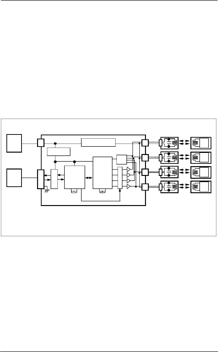
Circuit block configuration of the ME-MR23 Module is shown below.
Fig. 2-1 Circuit Block Diagram of ME-MR23
2.2 Module Configuration
Configuration of ME-MR23 Module is shown below.
(1) Main Module ・・・ 1 piece
(2) Antenna Module ・・・ 4 pieces
(3) Antenna Cable ・・・ 4 pieces (with ferrite core)
+9V
Detect-
or
Tag
IC
6MHz 13.56MHz
+12V
Host
PC RX
TX
Tag
IC
Tag
IC
Tag
IC
Selector
RS232C Transceiver
IC
Controller
IC
Power
12V Regulator
Regulator
+5V
RS232C
Converting IC
Main Module Antenna
Module Card
Coil-on-Chip RFID ME-MR23
MAXELL SEIKI CONFIDENTIAL 3
3 Outer Dimension
3.1 Outer Dimension Diagram of Reader/Writer Module
3.1.1 Reader/Writer Module
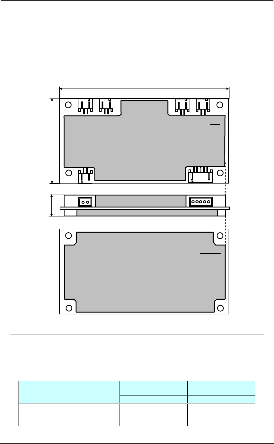
Outer dimension of ME-MR23 Module is as shown in the drawing below. Refer to the following
table for type number of housings matching connectors CN101, CN102, CN211 to CN241.
図3-1-1 Outer Dimension Drawing of Reader/Writer Module
Module Dimension: 100mm × 50mm × 14mm (standard value)
Board Dimension: 100mm × 50mm × 1.2mm thick (standard value)
Dimension of Mounting Hole: φ3.2mm × 4
Equipped connector
(post) Matching plug
Connector No.
Side entry type Housing
CN101 S5B-PH-SM4-TB PHR-5
CN102,CN211,CN221,CN231,CN241 S2B-PH-SM4-TB PHR-2
BOTTOM
100.0±1.0
50.0±1.0 Max 14.5
CN102 CN101
TOP
CN211 CN221 CN231 CN241
Unit: mm
Coil-on-Chip RFID ME-MR23
MAXELL SEIKI CONFIDENTIAL 4
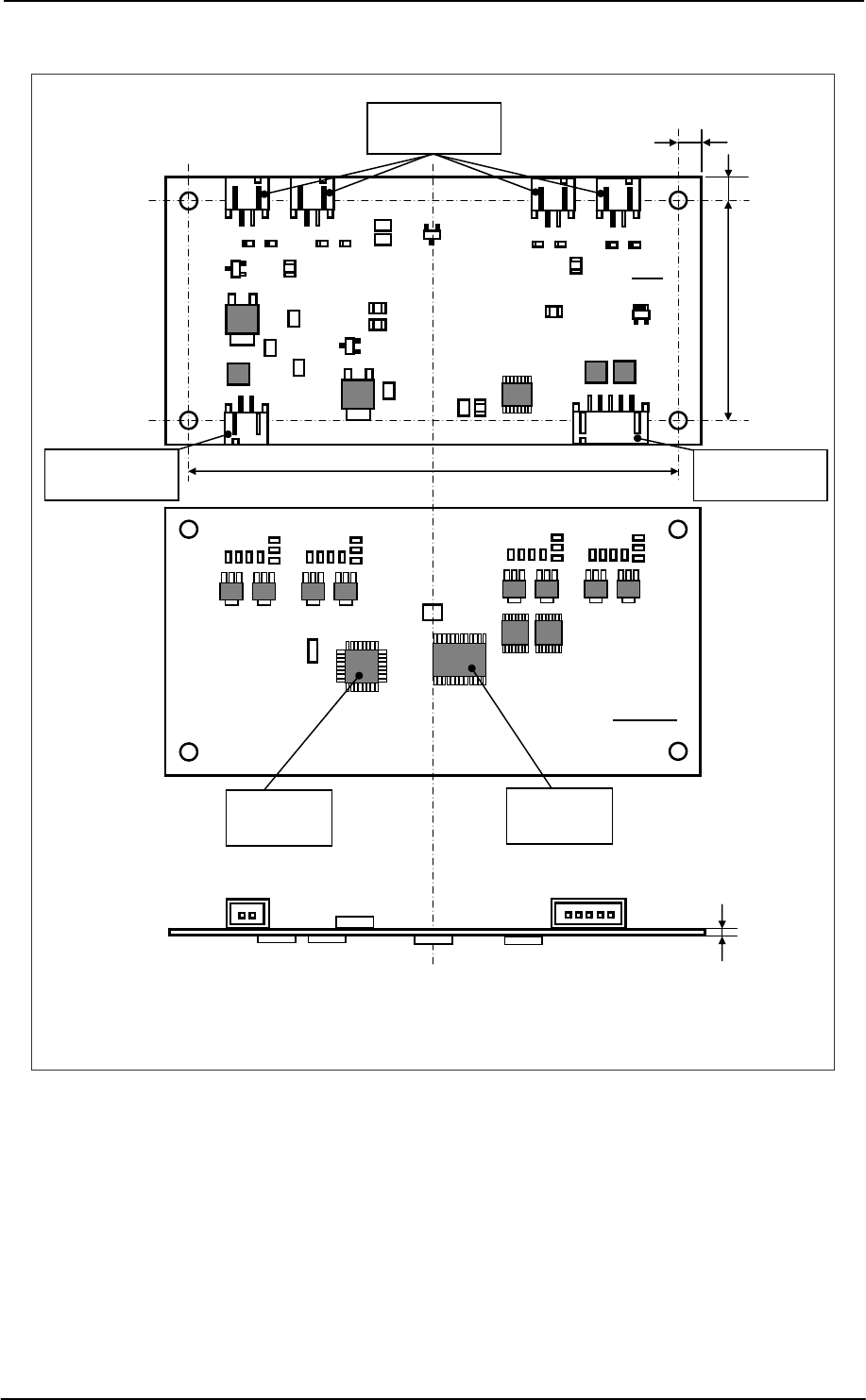
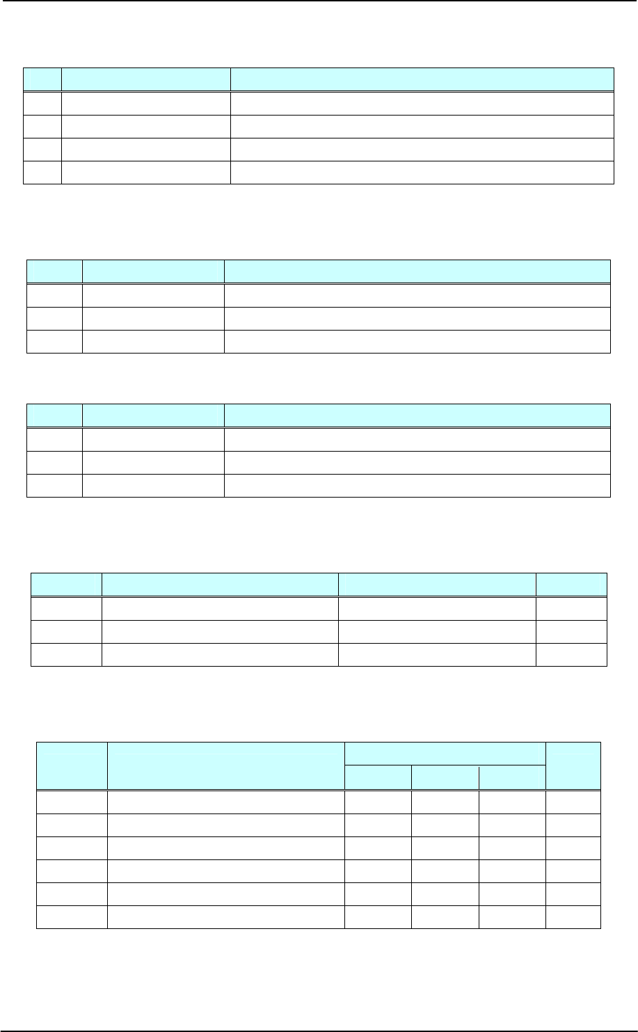
3.1.2 Component Layout of Reader/Writer Module
Fig. 3-1-2 Component Layout of Reader/Writer Module
Antenna Connector
PH 2P
Control IC
MP1 Transceiver
IC
TOP
BOTTOM
Max 1.3
90.0±0.2
40.0±0.2
(5)
Unit: mm
(5)
CN102 CN101
CN211 CN221 CN231 CN241
Power connector
PH 2P Host connector
PH 5P
Coil-on-Chip RFID ME-MR23
MAXELL SEIKI CONFIDENTIAL 5
3.2 Outer Dimension Drawing of Antenna
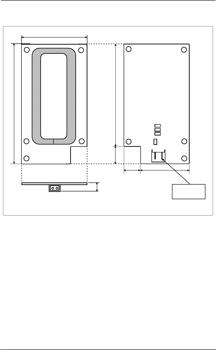
Outer dimension drawing of ME-MS01M-B-ANT is shown below.
Fig. 3-2 Outer Dimension Drawing of Standard Antenna
Module Dimension: 70mm × 39mm × 8mm (standard value)
Board Dimension: 70mm × 39mm × 1.2mm thick (standard value)
Mounting Hole Dimension: φ3.2mm × 5
39.0
±
0.3
70.0±0.5
60.0±0.5
2
9
.
5
±
0
.2
Max 10.0
(9.5)
(10)
Antenna Connector
PH 2P
Unit: mm
CN401
Coil-on-Chip RFID ME-MR23
MAXELL SEIKI CONFIDENTIAL 6
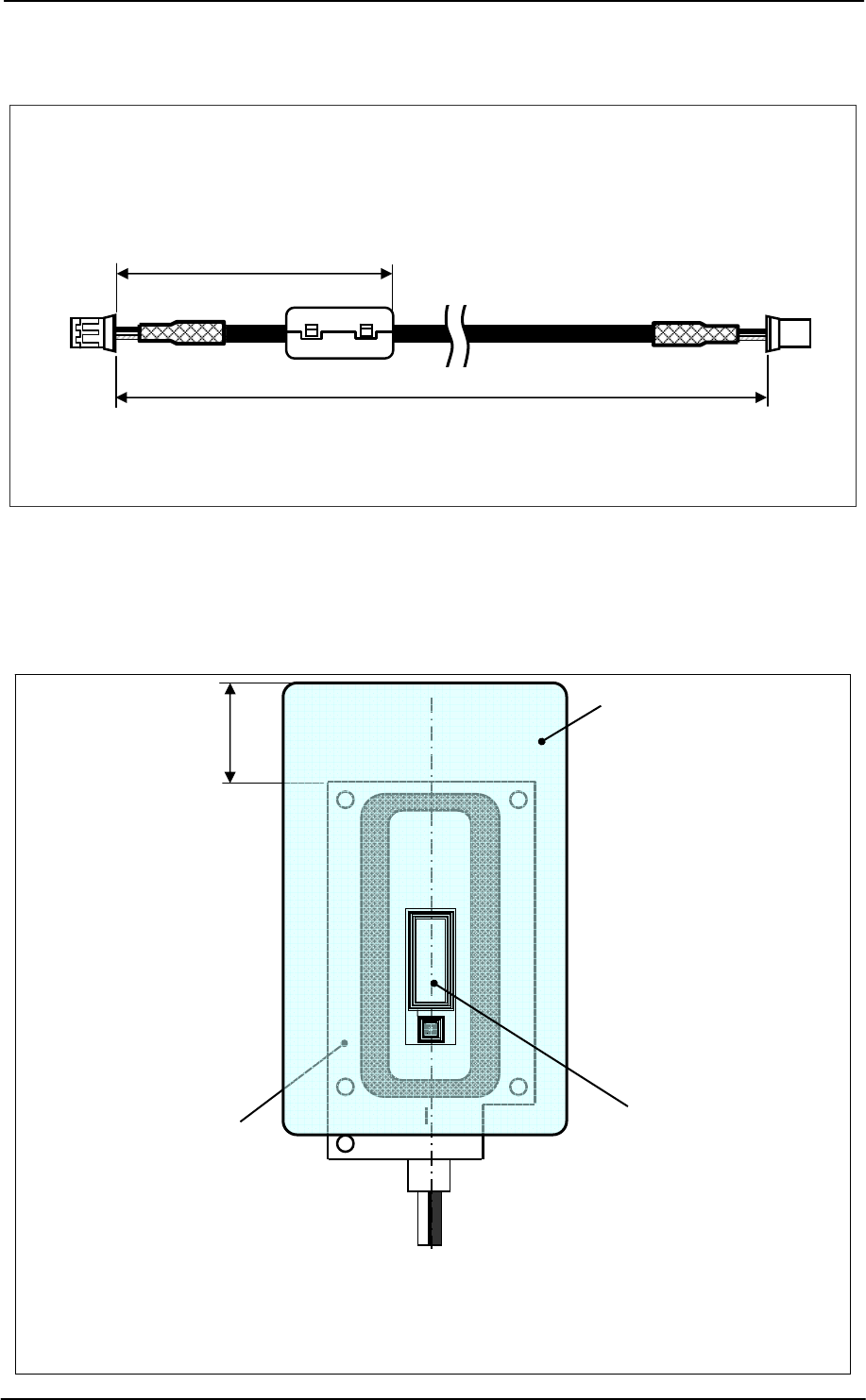
3.3 Appearance of Exclusive Antenna Cable
Appearance of exclusive antenna cable is shown below.
Cable length : 500 mm (standard value)
Connector housing: For PH-2pin
Ferrite core : TDK ZCAT1325-0530A 1 turn
Fig. 3-3 Appearance of Exclusive Antenna Cable
3.4 Positioning of Card
The card and antenna board shall be so positioned that the distance between the end of card and
that of antenna board is 20 mm in longitudinal direction, and that the card and the board are centered
in horizontal direction.
Fig. 3-4 Positioning of Card
Antenna board Booster coil
(inside the card)
500±15mm Antenna side
Reader/Writer side
100 to 130mm
20mm
Card
Coil-on-Chip RFID ME-MR23
MAXELL SEIKI CONFIDENTIAL 7
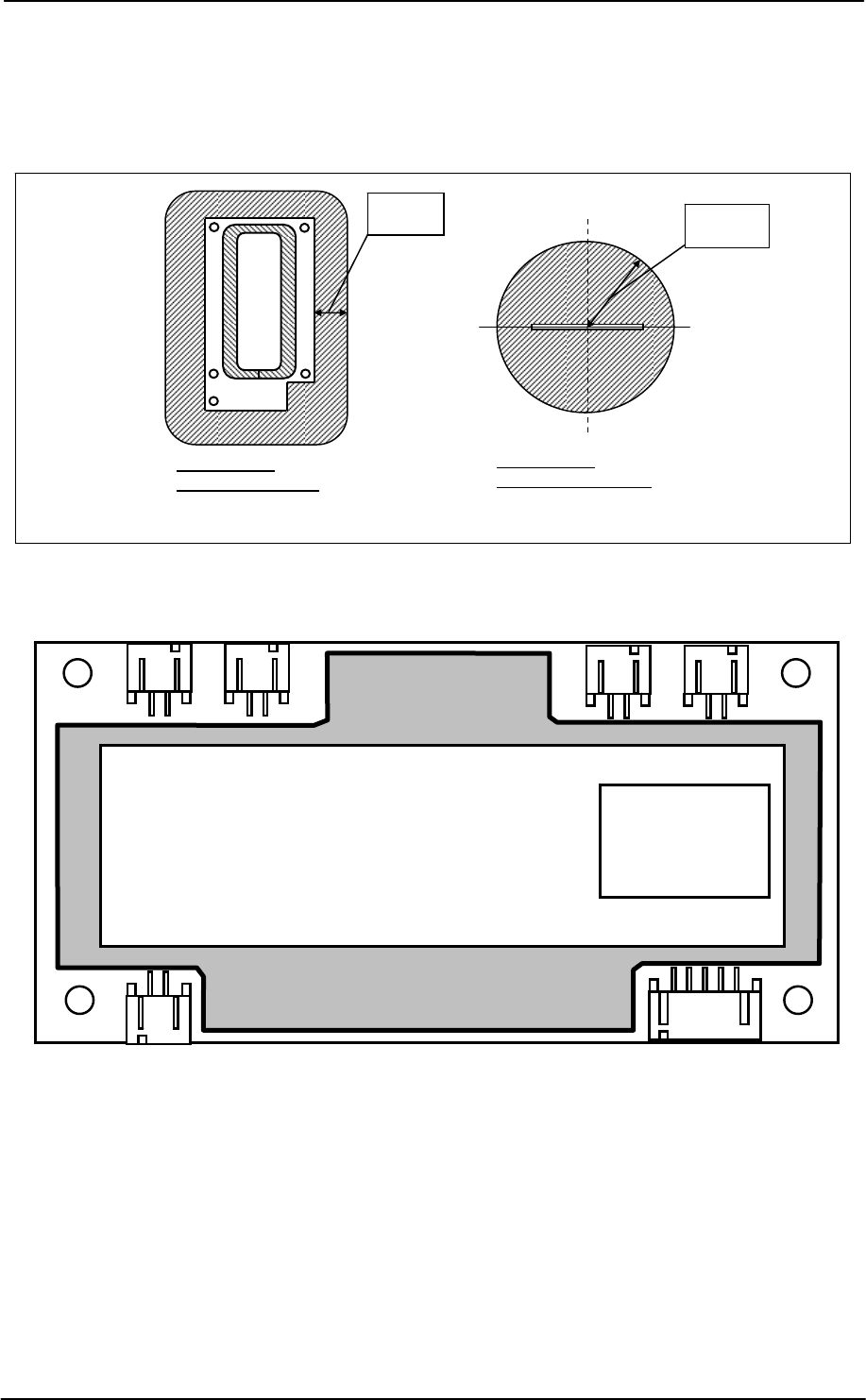
3.5 Restriction of Metallic Parts
Do not place metallic parts (magnetic materials) within the range of 20 mm from the end of antenna
board in horizontal direction, and within the range of 40 mm radius from the center of antenna board
in longitudinal direction (except for small metallic parts such as mounting screws)
Fig. 3-5 Restriction of Metallic Parts Peripheral to Antenna
4 Marking
Marking of nameplate shall be as shown below.
■ Color: White
■ Outer Dimension: 25.0 mm × 85.0 mm
■ Contents of Printed Characters
・Serial No.: Indicated in six digits
・Lot No.: Indicated in four digits
First digit: the last one digit of the year of manufacture in the Christian era
Second digit: month of manufacture (October: X, November: Y, December: Z)
Third and fourth digits: two digits of date of manufacture
・ Indication of type designated by Ministry of Internal Affairs & Transmissions: No. EC-08009
Reader Writer ME-MR23M4-A-SG
Manufactured by Maxell Seiki, Ltd. SEGA CORPORATION
MIC/KS
総務省指定
第 EC-08009 号
Lot No.
Serial No.
Restriction in
horizontal direction
20 mm
Restriction in
longitudinal direction
40 mm
Coil-on-Chip RFID ME-MR23
MAXELL SEIKI CONFIDENTIAL 8
5 Specifications of Reader/Writer Module
5.1 Environmental Characteristics
No Item Specification
1 Operating temperature 0 to 45℃
2 Operating humidity 20 to 80%RH (without condensation)
3 Storage temperature -10 to 60℃
4 Storage humidity 20 to 80%RH (without condensation)
5.2 Physical Specification
5.2.1 Main board (1 piece)
No. Item Specification
1 Outer dimension 100mm (D) ×50mm (W)×14mm (H max)
2 Material of board Glass epoxy FR-4 t = 1.2mm 4-layer
3 Weight 45g±20% × 1 piece (with shield)
5.2.2 Antenna board (4 pcs.)
No. Item Specification
1 Outer dimension 70mm (D) ×39mm (W) × 10mm (H max)
2 Material of board Glass epoxy FR-4 t = 1.2mm 2-layer
3 Weight 7g±20% × 4 pieces
5.3 Electrical Characteristics
5.3.1 Absolute maximum rating
Symbol Parameter Rating Unit
VCC VCC terminal -0.3 to 20 V
VI RXD terminal ±13 V
VO TXD terminal ±13 V
5.3.2 Electrical Characteristics
(VCC = 12V, GND = 0V, Ta = 0 to 45℃, unless otherwise specified)
Range
Symbol Parameter Min. Std. Max. Unit
VCC Power (+12V) 11.0 12.0 13.0 V
VOH TXD H output voltage (load 3kΩ) 4.5 5.4 − V
VOL TXD L output voltage (load 3kΩ) − -5.4 -4.5 V
VIH RXD H input voltage 2.4 5.4 13.0 V
VIL RXD L input voltage −13.0 -5.4 0.8 V
Rin RXD input resistor 3 5 7 kΩ
Coil-on-Chip RFID ME-MR23
MAXELL SEIKI CONFIDENTIAL 9
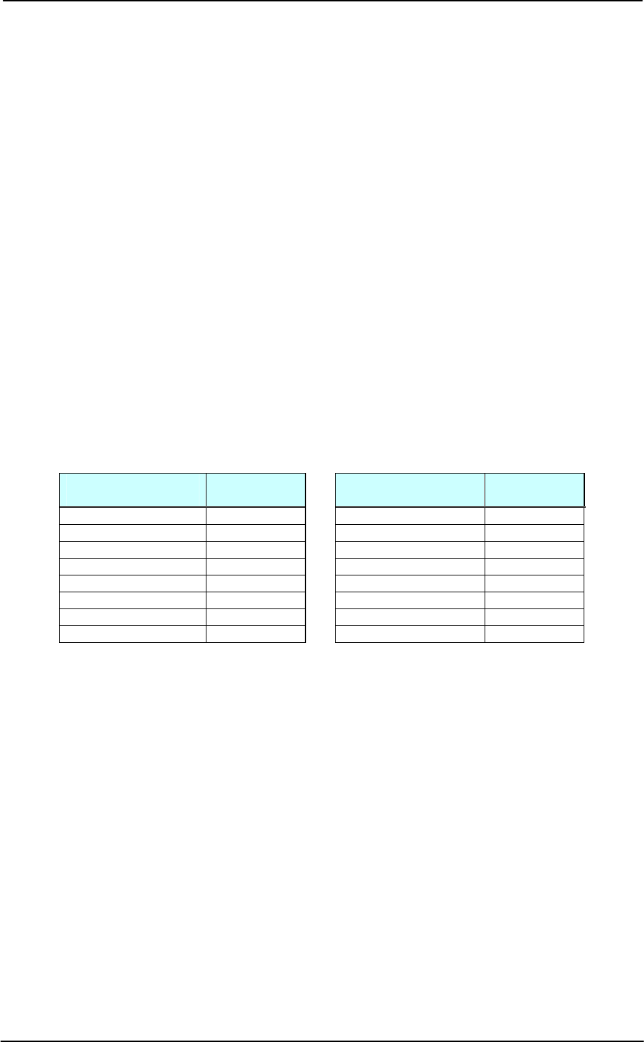
5.3.3 Electrical Performance
Item Standard
Supply voltage 12.0±1.0V
Consumed current※
1) Max. 200mA
(Operation status: main condition is carrier ON)
2) Max. 40mA
(Idle status: main condition is carrier OFF)
Carrier frequency 13.56MHz±15ppm or less
Data rate 26.48kbps
Quality of
transmission
・ Transmission distance
Min. 3.0mm to Max. 5.0mm (in case of one/two IC card(s))
(from surface of coil on antenna board to surface of card)
・ Allowed horizontal displacement
Longitudinal direction (longer side) ±3.0mm /
horizontal direction (short side) ±1.0mm
・ Number of card for which transmission is available with one antenna)
Two cards at maximum (to be inserted in the arrowed direction of card
design)
1) During transmission, amp gain shall be set at most suitable value at host
computer.
2) Do not place metallic or magnetic materials around the antenna.
Number of antenna
which can be
connected Four antennas
Antenna switching
method Host command method, carrier output for one antenna only
(refer to 6.1 for details)
Setting of receiving
circuit parameters
Register setting by command
・ Slice level setting: four steps
・ Amp gain setting: 16 steps
(refer to 6.1.1 for details)
Percentage of carrier
ON/OFF Percentage of ON: 50% or less
Wait time until
transmission 50ms after power on
* The above values are just for reference, not guaranteed values. They may vary depending on
system operating environment. Evaluate in actual system environment and adjust transmission
distance, gain setting, and horizontal displacement, etc. to ensure reliable transmission.
5.4 Interface Specification
5.4.1 Location of host connector terminal (CN101: PH-5pin)
Terminal Name of terminal Input/output Function
1 TXD Output Transmitted data signal
2 GND - GND(0V)
3 RXD Input Received data signal
4 GND - GND(0V)
5 GNDS - GND for shield
Coil-on-Chip RFID ME-MR23
MAXELL SEIKI CONFIDENTIAL 10
5.4.2 Location of antenna connector terminal (CN211 to CN241: PH-2pin)
Terminal Name of terminal Function Remark
1 SIGNAL Analog signal Core wire side
2 VANT Power to antenna Cable shield side
5.4.3 Location of external power supply connector terminal (CN102: PH-2pin)
Terminal Name of terminal Function Remark
1 VCC Power terminal(+12V)
2 GND GND(0V)
5.5 RXD / TXD Transmission Specification
Item Specification
Transmission speed (actual speed*1) 19,200 bps(18,750 bps)※2
38,400 bps(37,500 bps)
Transmission method RS232C semi-double
Synchronization method No synchronization
Flow control None
Start bit rate 1-bit
Data rate 8-bit
Stop bit rate 1-bit
Parity bit rate 1-bit/even number
※1 Controller incorporated in this module employs 6MHz oscillator. Because transmission speed is
generated by its frequency-dividing, actual speed in this module is the value in parenthesis.
※2 When supplying power (system reset), transmission speed is 19,200bps.
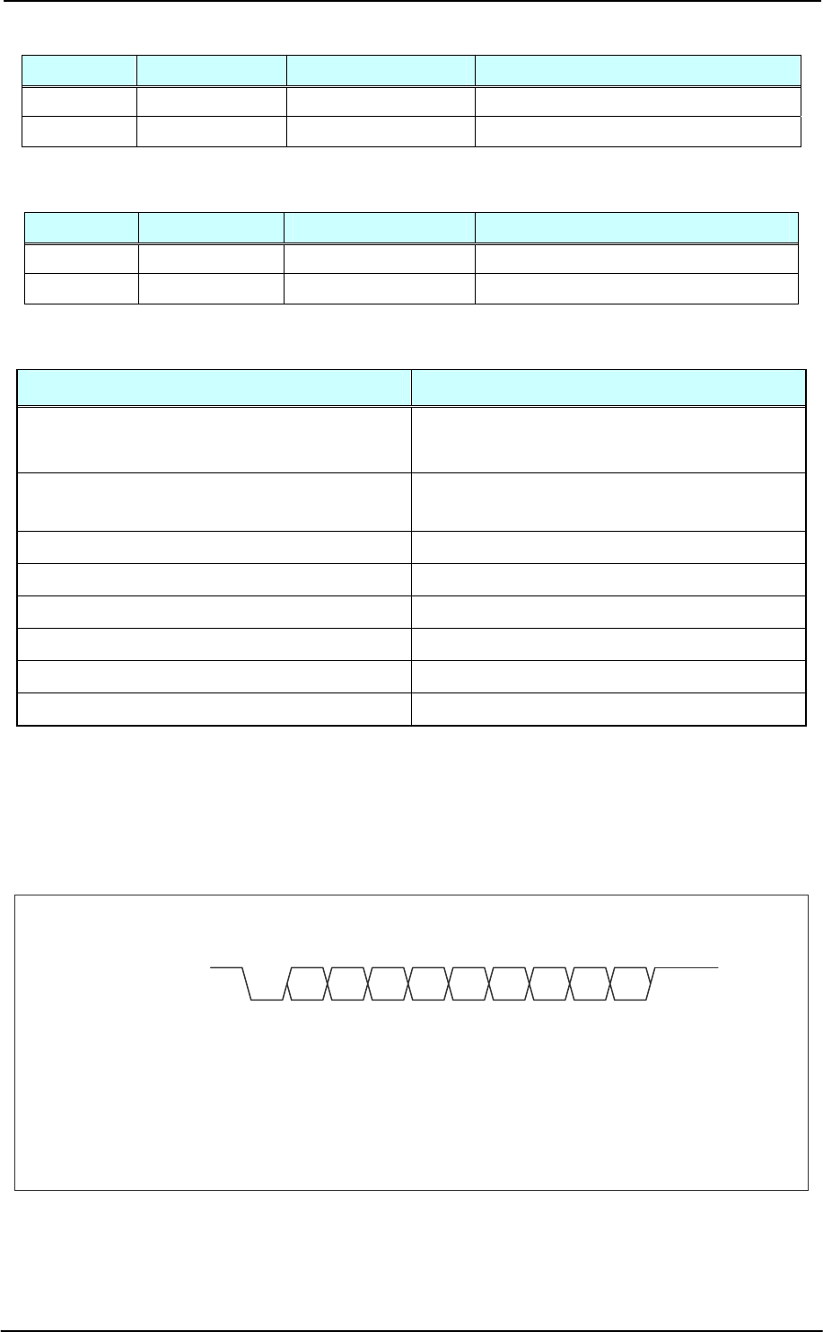
RXD / TXD data format
1ST-8DATA-1PAR-1SP
Fig. 5-5 Data Format
ST LSB MSB PAR SP RXD or TXD
ST : STart bit
LSB : Least Significant Bit
MSB : Most Significant Bit
PAR : PARity bit
SP : StoP bit
Coil-on-Chip RFID ME-MR23
MAXELL SEIKI CONFIDENTIAL 11
6 Description of Operation
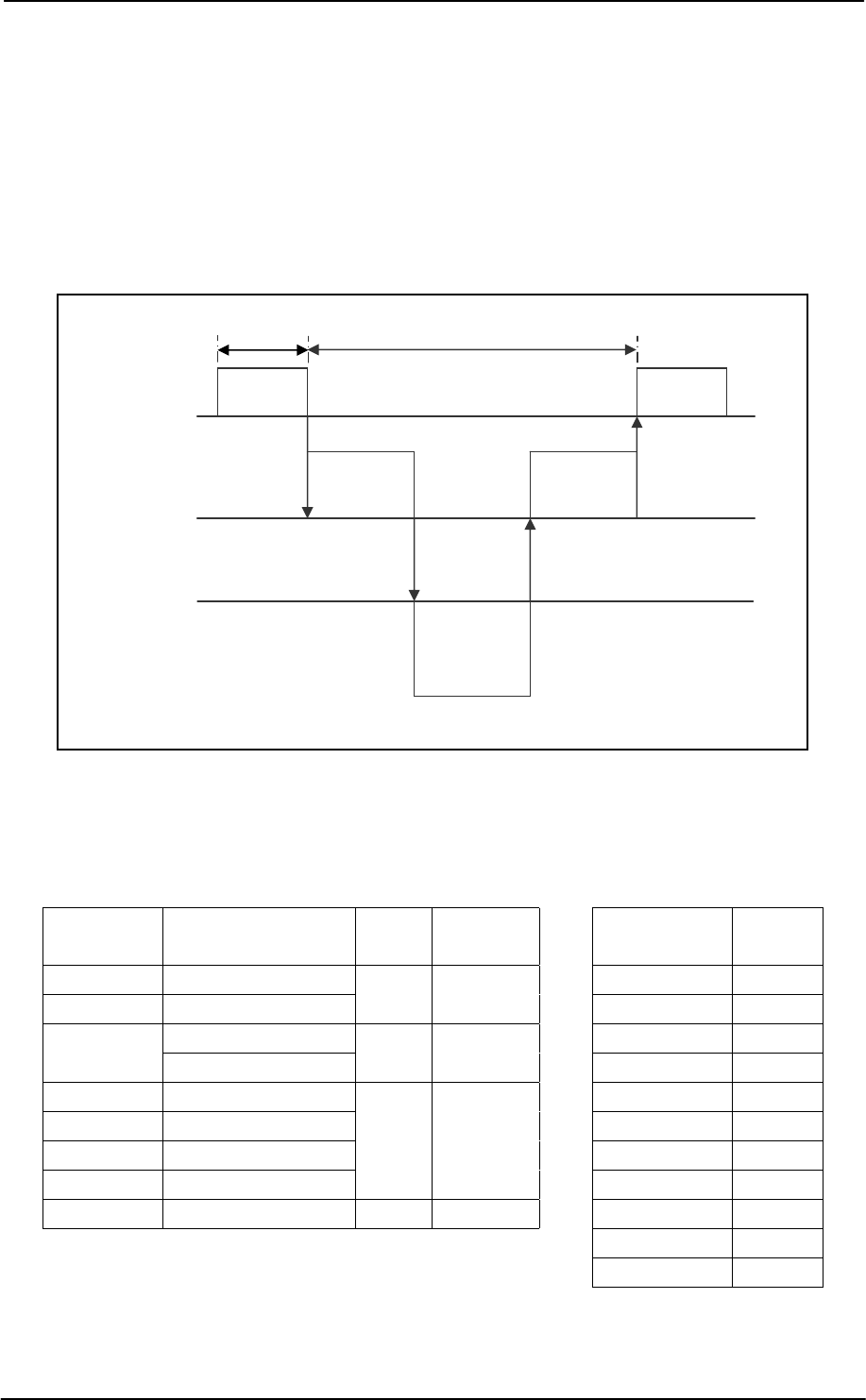
6.1 Transmission Protocol
Image of transmission protocol between host computer, Reader/Writer Module, and RFID chip is
shown in Figure 6-1.
Reader/Writer Module receives command and data from the host computer and transmits them to
RFID chip. It also receives response and data from RFID chip, and judges whether transmission is
completed or not, and then transmits the results to the host computer,
Fig. 6-1 Image of Transmission Protocol
※3 Keep the time shown in Table B as timeout own time at minimum
(take margins into consideration for design).
Command Frame configuration Byte
number
Timeout
time [ms] Command Timeout
time[ms]
COUNT COUNT+CT_NUM REQ 120
CHANGE CHANGE+BAUDRATE 2 5.0
SEL 45
TEST+TEST_CODE READ 80
TEST TEST+RF_OFF 3 8.8
WRITE 100
WRITE WRITE+DATA WRITE_NOP 40
WRITE_NOP WRITE_NOP+DATA WRITE_ST 100
WRITE_ST WRITE_ST+DATA HALT 40
HALT HALT+UID
5 15.3
COUNT 60
SEL SEL+UID+KEY 9 28.6 TEST 5
TEST(RF_OFF) 5
RESET 5
Transmission
of command/
data
Command
processed,
response
processed
Receipt of
response/
data
Reader/Writer
module
RFID chip
B: Monitoring (timeout judgment)※3
Response
processed
Issue of
command
Host
A
・ Because reader/writer module is not set for timer between
characters, complete transmission of designated byte rate
within the timeout time indicated in Table A.
・ Take an interval of more than 5ms between completion o
f
receipt of response and start of next command transmission,
Table A: List of receiving timeout times of multiple bytes
command
Table B. List of theoretical timeout values from
transmission of command to receipt of response
Coil-on-Chip RFID ME-MR23
MAXELL SEIKI CONFIDENTIAL 12
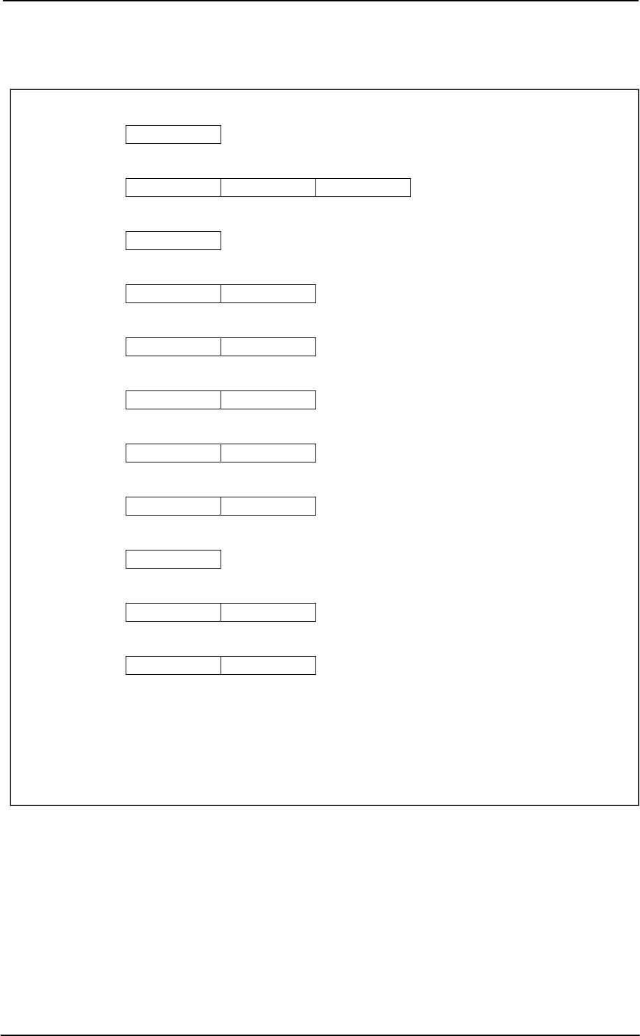
6.2 Command
Command frames from host computer to Reader/Writer Module and description of them are shown
below.
bit7 1B LSB
【TC1】 REQ
bit7 1B LSB 4B● 4B●
【TC2】 SEL UID KEY
bit7 1B LSB
【TC3】 READ
bit7 1B LSB 4B●
【TC4】 WRITE DATA
bit7 1B LSB 4B●
【TC5】 WRITE_NOP DATA
bit7 1B LSB 4B●
【TC6】 WRITE_ST DATA
bit7 1B LSB 4B●
【TC7】 HALT UID
bit7 1B LSB bit7 1B LSB
【TC8】 COUNT CT_NUM
bit7 1B LSB
【TC9】 RESET
bit7 1B LSB 2B●
【TC10】 TEST TEST_CODE
bit7 1B LSB 2B●
TEST RF_OFF
B : Byte
*4: Writing to RFID chip is done by WRITE command only.
WRITE_NOP and WRITE_ST execute movement of write pointer only, but DUMMY DATA (4-Byte) is required.
● When processing multiple byte data (ex. UID, TEST_CODE) for data transmission, take the following steps.
“Transmit upstream byte by LSB First. → Transmit next byte by LSB First. MSB with the lowest byte is the last
transmission.”
※4
※4
※4
Coil-on-Chip RFID ME-MR23
MAXELL SEIKI CONFIDENTIAL 13
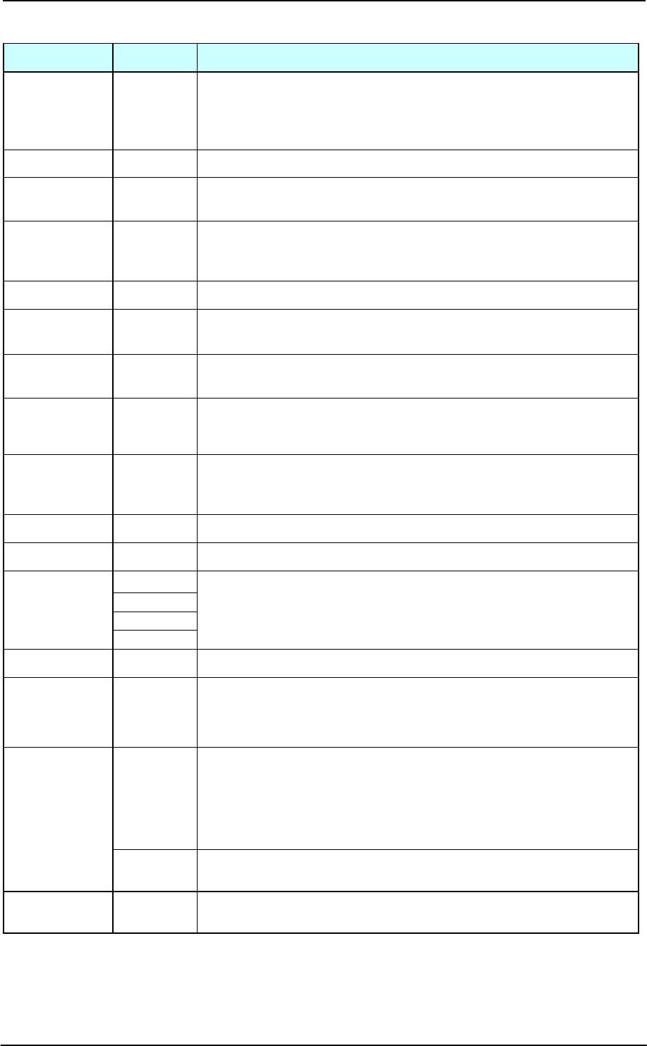
Command to Reader/Writer Module
Command Code[Hex] Description of Functions
REQ 4E
Requesting communication with RFID chip.
However in case of REQ command with carrier OFF, no response from RFID
chip, because it serves as a command requesting carrier ON (transfer to
operation status).
SEL 2E Selecting a specific RFID chip.
UID Existing
(4-byte)
Unique ID of RFID chip.
It is already written at factory and cannot be changed.
KEY Random
(4-byte)
Key of RFID chip (code).
Checking KEY against SEL command, and executing access restriction
depending on match or mismatch.
READ 0E Reading memory of RFID chip (128-byte collectively)
WRITE CE
Increasing write pointer of RFID chip with an increment (+1) and write to
memory (4-byte unit).
DATA Random
(4-byte)
Data to be written.
It may be invalid depending on access restriction, but 4-byte data is required
WRITE_NOP 8E
Increasing write pointer of RFID chip with increment (+1).
Actual writing is not executed.
But dummy data (4-byte) at transmission of command is required.
WRITE_ST EE
Returning write pointer of memory to zero (position of Serial No.0).
Writing to RFID chip is not executed.
But data at transmission of command (4-byte, dummy) is required.
HALT AE Halting a specific RFID chip.
COUNT 6E Decreasing down counter of RFID chip with decrement (-1).
03
0C
30
CT_NUM
C0
Specifying counter for decrement.
Select one CT_NUM code corresponding any of Counter 1 to 4.
Counter1: 03h, Counter2: 0Ch, Counter3: 30h, Counter4: C0h
RESET 7E Initializing controller.
TEST 5E
Setting parameters of analog characteristics of transceiver/antenna
selection. Transmission of carrier from module is checked by TEST
command (TEST_CODE:00**). If the response is NOT (6Ah), the carrier is
not transmitted.
F0**
(2Byte)
Parameter of antenna selection.
Shifting antenna to be activated with lower 1-byte (** mentioned on the left).
01h: select antenna to be connected with CN211
02h: select antenna to be connected with CN221
03h: select antenna to be connected with CN231
04h: select antenna to be connected with CN241
TEST_CODE
00**
(2Byte)
Parameter of receiving gain characteristic of transceiver.
Shifting receiving gain with lower 1-byte (** mentioned on the left).
RF_OFF 80**
(2Byte)
Stopping carrier by TEST+RF_OFF
Lower 1-byte (** mentioned on the left) is at random.
Coil-on-Chip RFID ME-MR23
MAXELL SEIKI CONFIDENTIAL 14
6.2.1 Parameter of Analog Characteristic
Most suitable parameter of analog characteristic depends on transmission characteristic of each
RFID chip and positional relationship between antenna coil on Reader/Writer Module and RFID
chip. Estimate gain setting with least transmission error and set it as default value.
When accessing other RFID chip or repositioning (including insertion and withdrawal), optimize the
parameter of analog characteristic to match with the receiving characteristic from RFID chip.
When transmission errors occurs and transmission is not possible despite of retrying, provide
software processing to shifting set gain values up and down automatically. We recommend you
should shift the set gain values above and below the default value, taking operating environment
(supply voltage, ambient temperature), dispersion of transmission distance, dispersion of
transmission performance of RFID chip into consideration.
・ Recommended setting for evaluation
Default 29 → 2A → 28 → 2B → 27 → 2C → 26 (→ return to default value)
(retry for a few times at each gain)
Set gain values of receiving amplifier are shown below.
Set values of receiving amp gain
6.2.2 RESET command
It is possible to issue RESET command even in case of sequence of executing other command.
However, because all the transmission sequences are interrupted to respond to RESET command,
we cannot guarantee internal operation, depending on the transmission sequence being executed.
Therefore, issue RESET command after a considerable time elapsed since completion of the
previous command transmission sequence.
We recommend that you should issue RESET command only in case of trouble, for example,
when ”response is not returned” as a result of waiting response from Reader/Writer Module.
You cannot do 40-second timer deactivation by RESET command after 40-second timeout
(impossible to communicate with RFID chip). External reset or turning power off and on is
required.
Parameter of analog
characteristic Amp gain Parameter of analog
characteristic Amp gain
0020h 17 dB 0028h 33 dB
0021h 19 dB 0029h 35 dB
0022h 21 dB 002Ah 37 dB
0023h 23 dB 002Bh 39 dB
0024h 25 dB 002Ch 41 dB
0025h 27 dB 002Dh 43 dB
0026h 29 dB 002Eh 45 dB
0027h 31 dB 002Fh 47 dB
Coil-on-Chip RFID ME-MR23
MAXELL SEIKI CONFIDENTIAL 15
6.3 Response
Responses returned from Reader/Writer Module to host computer are shown below.
bit7 1B LSB
【RC1】 OK
bit7 1B LSB
【RC2】 RETRY
bit7 1B LSB
【RC3】 NG
bit7 1B LSB 4B●
【RC4】 OK UID
bit7 1B LSB 128B●
【RC5】 OK DATA
bit7 1B LSB bit7 1B LSB
【RC6】 OK VALUE
bit7 1B LSB
【RC7】 NOT
B : Byte
●
When processing multiple byte data (ex. UID, TEST_CODE) for data transmission, take the following steps.
“Transmit upstream byte by LSB First. → Transmit next byte by LSB First. MSB with the lowest byte is the last
transmission.”
Response to Host Computer
Response Code[Hex] Description of Function
OK 0A
Response in case transmission is successful.
Response is given when any of ATQ, ATQ_C, and ACK is received without
transmission error or in case of processing command by controller.
RETRY CA
Response requesting retry to send command when transmission error
occurs.
NG 3A
Response in case /DETECT of Reader/Writer Module equals to 1.
In case of /DETECT = 1, the Reader/Writer Module decides there is no RFID
to communicate with and does not communicate with RFID chip.
UID Prearranged
(4-byte) Unique ID of RFID chip.
DATA Random
(128-byte)
Data of RFID chip.
If condition of access to memory is set in advance, the data is that after
masking (the masking part is “0”).
VALUE Random
(1-byte)
Counter value after decrease of down counter of RFID chip with decrement
(-1).
NOT 6A
Response in case carrier is not transmitted from the module when giving
TEST command (TEST_CODE:00**).
Transmission of carrier from the module is checked by TEST command.
Coil-on-Chip RFID ME-MR23
MAXELL SEIKI CONFIDENTIAL 16
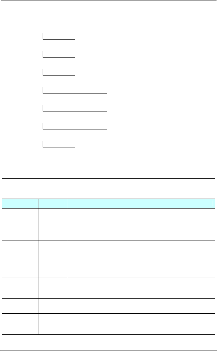
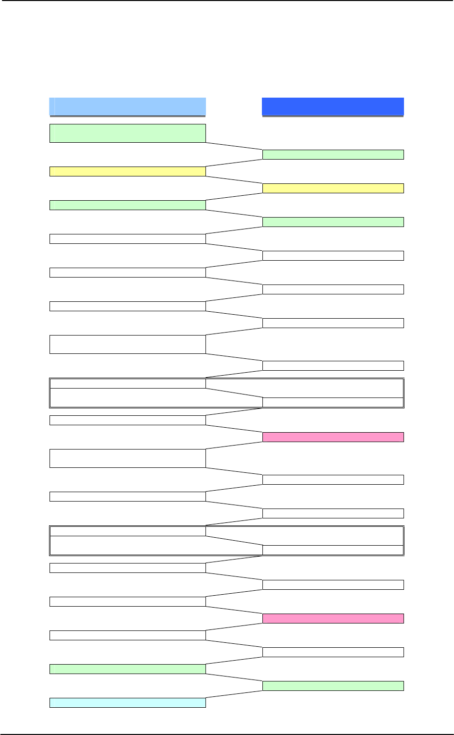
7 Example of Steps of Giving Commands
Example of giving commands for writing to DATA (data area) to RFID card is shown below.
Condition: Most suitable parameter of receiving gain characteristic is checked in advance and
transmitted after reset.
Command issued by host computer and
processing Response from reader/writer
TEST (check of carrier, existence of
RFID chip)
NOT (carrier OFF, RFID chip exists)
REQ (carrier ON)
RETRY (in normal case, carrier ON)
TEST (Gain setting)
OK
REQ (transmission command)
OK
SEL
OK
READ
OK (check of memory contents)
WRITE_ST (set the write pointer to
standard position)
OK
WRITE_NOP (moving write pointer)
* For this example, WRITE_NOP
by 4 times OK
WRITE (actual writing)
RETRY (transmission error occurs)
READ (recheck of data is required when
writing)
OK (check of memory contents)
WRITE_ST (returning write pointer)
OK
WRITE_NOP (moving write pointer)
* For this example, WRITE_NOP
by 4 times OK
WRITE (writing data again)
OK
READ
RETRY (transmission error occurs)
READ (simple retry when reading)
OK (end of expected processing)
TEST+RF_OFF (carrier OFF)
OK
All processes completed

Coil-on-Chip RFID ME-MR23
MAXELL SEIKI CONFIDENTIAL 17
8 Precautions Before Use
・ This Reader/Writer Module itself may not meet EMI (Electromagnetic Interference) standard.
Give consideration to conformity of the system to EMC standard as required for intended use and
destination of your system.
・ Do not place metallic parts between Reader/Writer Module and RFID chip. Keep antenna away
from conductive objects such as metallic frame. If such object is close to antenna, it may impair
transmission characteristic.
9 Precautions for Handling
・ This Reader/Writer Module is precision apparatus. Do not disassemble or modify it. Otherwise, it
may cause malfunction, failure, fire, or electric shock.
・ Before handling the module, discharge electrostatic charge from your body. Do not drop, strike,
bend, or give impact on the module.
・ Do not touch with wet hand. Otherwise, it will cause failure.
・ This module employs metallic shield plate. When you handle the module, do not touch its edge.
The edge is sharp and your finger may get a cut.
・ Use exclusive card compatible with this module only. Do not insert any object such as iron plate or
coin. Otherwise, it may cause failure.
・ Never remove cables during access to the card. Otherwise, it may cause collapse of data in the
card or the card itself.
・ Do not touch or remove the card during access to the card. Otherwise, it may cause collapse of
data in the card or the card itself.
10 Cautions for Use
・ When required transmission is completed, stop the carrier. If carrier output continues, RFID chip
may generate heat. For safety, the Reader/Writer Module automatically stops carrier in about 40
seconds after the start of carrier output. If you turn off the power and turn it on again, the module is
recovered.
・ For safety, provide the host computer with power protection against overcurrent due to short-circuit of
components in this module, etc.
・ Be sure to carry out Read Verify check after writing.
・ When retrying because of transmission error, readjust receiving amp gain.
・ Do not use this module with reversed combination of antenna board and Reader/Writer board.
Otherwise, it may impair transmission performance (excluding cables).
・ Turn off the power before removing or inserting the card. Otherwise, it may cause failure.
・ Do not bend this module at its portion close to the housing of antenna cable. Otherwise, it may
cause breakage of conductor.
・ Insert the card in the arrowed direction in such a manner that the face is visible. If the direction is
wrong, transmission error may occur. In such case, insert it in correct direction.

Coil-on-Chip RFID ME-MR23
MAXELL SEIKI CONFIDENTIAL 18
Request with regard to safety design
・ We make our best efforts to improve quality and reliability of our products. Nevertheless,
semiconductor products may have trouble or malfunction. We request you to give
enough consideration to safety design of your system, such as redundant design,
anti-spreading-fire design, malfunction preventing design, to avoid injury, fire, social
damage, etc. resulting from failure or malfunction of our semiconductor products.
・ This Reader/Writer Module is designed for use in general electronic equipment (office use,
telecommunications, measuring, household, etc.), but not designed and manufactured for
use in equipment or system used in serious condition affecting people’s lives. If you
consider use of this module for equipment or system for special applications such as
transportation, vehicular, medical, aerospace, nuclear control, or undersea data
communication, please contact the sales contact person or authorized product distributor
of Maxell Seiki Ltd.
Notes on use of this material
・ This material is intended as a reference to assist our customers in purchase of
semiconductor products of Maxell Seiki Ltd., meeting the customer's application. For
technical information described in this material, it does not convey any license under any
intellectual property rights, or any other rights, belonging to Maxell Seiki Ltd.
・ Maxell Seiki Ltd. assumes no responsibility for any damage, or infringement of any
third-party's rights, arising from the use of any product data, diagrams, charts, or circuit
application examples contained in this material.
・ Prior written approval of Maxell Seiki Ltd. is required to reprint or reproduce this material in
whole or in part.
・ All the product information and product specification described in this material represent
information on products at the time of publication of this material, and are subject to
change without notice. Therefore, we recommended that customers contact the sales
contact person or authorized product distributor of Maxell Seiki Ltd. before purchasing our
products to ensure that the information in this material is the latest.
・ Before starting actual product design, delivery specifications shall be exchanged with
Maxell Seiki Ltd., and the product design shall be proceeded according to exchanged
delivery specifications.

Coil-on-Chip RFID ME-MR23
MAXELL SEIKI CONFIDENTIAL 19
This equipment has been tested and found to comply with the limits for a
Class B digital device, pursuant to Part 15 of the FCC Rules. These limits are
designed to provide reasonable protection against harmful interference in a
residential installation. This equipment generates, uses and can radiate radio
frequency energy and, if not installed and used in accordance with the
instructions, may cause harmful interference to radio communications. However,
there is no guarantee that interference will not occur in a particular installation.
If this equipment does cause harmful interference to radio or television reception,
which can be determined by turning the equipment off and on, the user is
encouraged to try to correct the interference by one or more of the following
measures:
-- Reorient or relocate the receiving antenna.
-- Increase the separation between the equipment and receiver.
-- Connect the equipment into an outlet on a circuit different
from that to which the receiver is connected.
-- Consult the dealer or an experienced radio/TV technician for help.
You are cautioned that changes or modifications not expressly approved by the
party responsible for compliance could void your authority to operate the
equipment.
This device complies with FCC RF radiation exposure limits set forth for an uncontrolled environment.
The antenna used for this transmitter must be installed to provide a separation distance of at least 20
cm from all persons and must not be co-located or operating in conjunction with any other antenna or
transmitter.