Maxon CIC SM-2102E Mobile radio for vehicle User Manual TABLE OF CONTENTS
Maxon CIC Corp. Mobile radio for vehicle TABLE OF CONTENTS
UserManual.wiki
>
Maxon CIC
>
SM 2102E User Manual
User Manual
Navigation menu
Upload a User Manual
Namespaces
Wiki Guide
HTML
PDF
Info
Views
User Manual
Discussion / Help
Navigation
![[텍스트 입력] 1 SM2402E / SM2102E TRANSMETTEUR MOBILE DESCRIPTION OPÉRATIONNELLE](https://usermanual.wiki/Maxon-CIC/SM-2102E/User-Guide-2152595-Page-15.png)
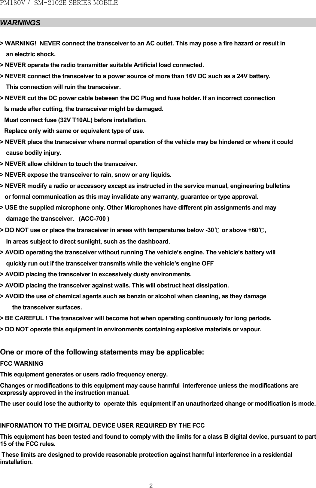
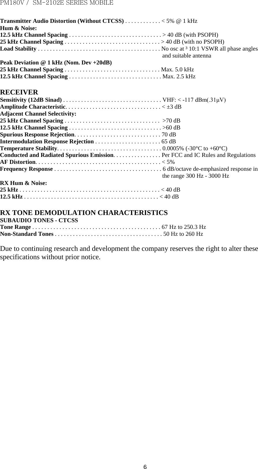
![[텍스트 입력] 2AVERTISSEMENTS > AVERTISSEMENT ! Ne connectez jamais le transmetteur à une Prise secteur. Ceci peut poser un risque d'incendie ou un résultat dans une décharge électrique. > N'actionnez jamais le chargement artificiel approprié d'émetteur de transmetteur connecté. > Ne connectez jamais le transmetteur à une source d'énergie de plus que C.C 16V tel qu'une batterie 24V. Cette connexion ruinera le transmetteur. > Ne coupez jamais le câble d'alimentation de C.C entre la fiche de C.C et le support de fusible, car ceci endommagera le transmetteur. > CONNECTEZ le fusible (32V T10AL) avant l'installation. Le Fusible peut seulement être remplacé par le même ou le type équivalent. > Ne mettez jamais le transmetteur où le fonctionnement normal du véhicule peut être gêné ou où il pourrait entraîner la blessure corporelle. > Ne permettez jamais aux enfants de toucher le transmetteur. > N'exposez jamais le transmetteur à la pluie, à la neige ou à aucun liquide. > Ne modifiez jamais un transmetteur ou un accessoire à moins que comme indiqué dans le manuel, les bulletins d'ingénierie ou la transmission formelle en tant que ceci puissent infirmer n'importe quelle garantie, garantie ou homologation. > UTILISEZ le microphone fourni (ACC-700B) seulement. D'Autres Microphones ont différentes affectations de broche et peuvent endommager le transmetteur. > N'utilisez pas ou ne mettez pas le transmetteur dans les zones avec les températures ci-dessous -30Ԩ ou au-dessus de +60Ԩ, ou dans les zones sujet à la lumière du soleil directe, telle que le tableau de bord d'un véhicule. > AVOID actionnant le transmetteur sans engine de véhicule de fonctionnement. La batterie du véhicule sera rapidement vidée de son alimentation électrique si le transmetteur transmet tandis que l'engine de véhicule est éteinte. > AVOID mettant le transmetteur dans les environnements excessivement poussiéreux. > AVOID mettant le transmetteur contre des murs. Ceci obstruera la dissipation thermique. > ÉVITEZ l'utilisation des agents chimiques tels que la Benzine ou l'Alcool en nettoyant, comme ils endommagent les surfaces du transmetteur. > PRENEZ SOIN ! Le transmetteur deviendra chaud quand fonctionnant continuellement pendant de longues périodes. > N'actionnez pas ce matériel dans les environnements contenant les matériaux explosifs ou la vapeur. Un ou plusieurs des déclarations suivantes peuvent s'appliquer : AVERTISSEMENT DE FCC Ce matériel produit ou utilise de l'énergie de fréquence de transmetteur. Les Modifications ou les modifications à ce matériel peuvent entraîner l'interférence néfaste à moins que les modifications soient expressément approuvées du manuel d'instruction. L'utilisateur pourrait détruire l'autorité pour actionner ce matériel si une modification ou une modification non autorisée est apportée. L'INFORMATION À L'UTILISATEUR D'APPAREIL NUMÉRIQUE REQUIS PAR LA FCC Ce matériel a été testé et avéré pour être conforme aux limites pour un appareil numérique de la classe B, conformément à la partie 15 des Réglementations de la FCC. Ces limites sont conçues pour assurer la protection raisonnable contre l'interférence néfaste dans une installation résidentielle. Les utilisations de Ce matériel et peuvent produire de l'énergie de fréquence de transmetteur. Sinon installé et utilisé selon les instructions, peut entraîner l'interférence néfaste aux transmissions de transmetteur. Cependant, il n'y a aucune garantie que l'interférence ne se produira pas dans une installation particulière.](https://usermanual.wiki/Maxon-CIC/SM-2102E/User-Guide-2152595-Page-16.png)
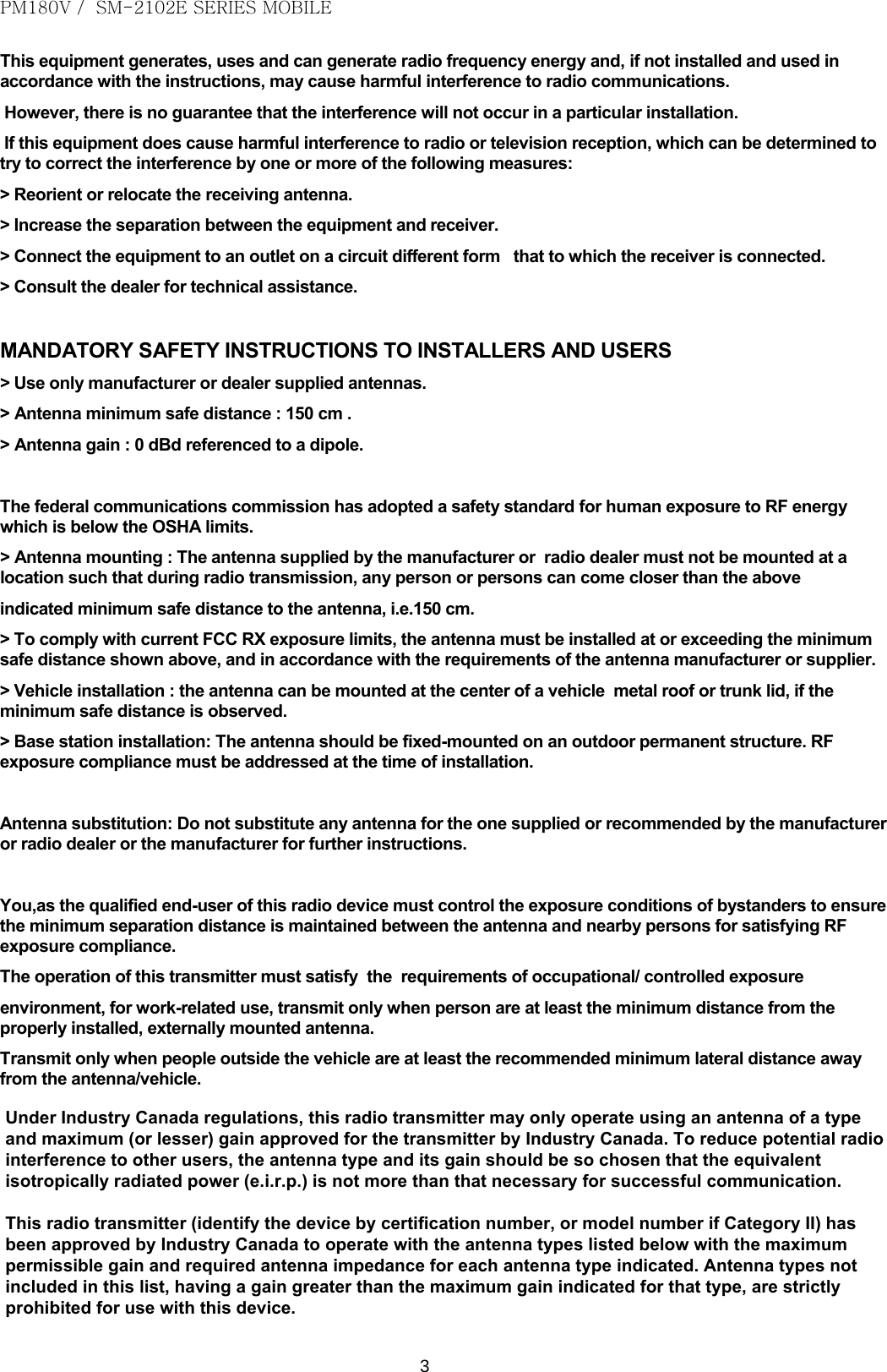
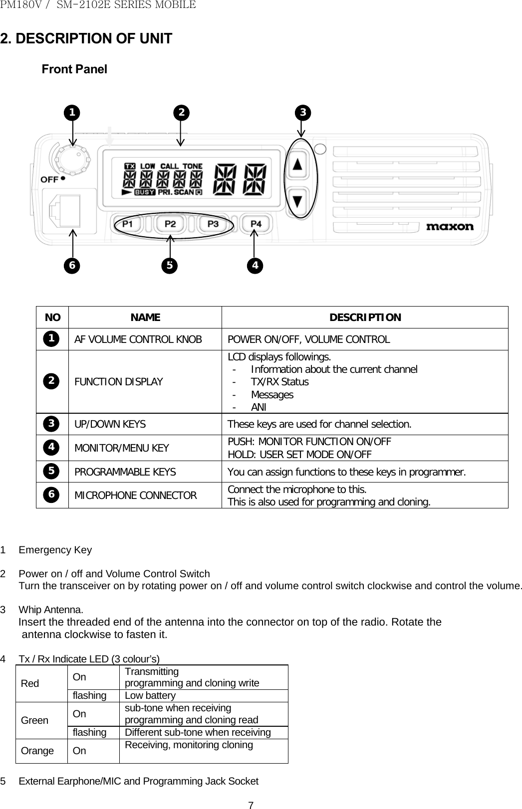
![[텍스트 입력] 3 Si ce matériel entraîne l'interférence néfaste à la réception de transmetteur ou d'émissions télévisées, qui peut être déterminée pour essayer de corriger l'interférence par un ou plusieurs des mesures suivantes : > Réorientez ou replacez l'antenne de réception. > Augmentez la distance de la séparation entre le matériel et le récepteur. > Connectez le matériel à un débouché ou à un circuit différent de celui auquel le récepteur est connecté. > Consultez le marchand de transmetteur pour l'assistance technique. INSTRUCTIONS DE SÉCURITÉ OBLIGATOIRES AUX INSTALLATEURS ET AUX UTILISATEURS > Utilisez seulement le constructeur ou les antennes fournies par distributeur. > L'Antenne doit être installée à une distance de sécurité minimum de 150 cm . > Gain d'Antenne : 0 dBd référencés à un dipôle. La Commission Fédérale des Communications a adopté une norme de sécurité pour l'exposition humaine à l'énergie de RF qui est ci-dessous les limites d'OSHA. > Support d'Antenne : L'antenne fournie par le marchand de constructeur ou de transmetteur ne doit pas être montée à un emplacement tels que pendant la transmission de transmetteur, toute personne ou les personnes peut venir plus étroitement que la distance de sécurité minimum ci-dessus indiquée à l'antenne, c.-à-d., 120 cm (4 pieds). > Pour se conformer aux limites d'exposition actuelles de la FCC RX, l'antenne doit être installée ou dépassant la distance de sécurité minimum affichée ci-dessus, et selon aux conditions du constructeur ou du fournisseur d'antenne. > Installation de Véhicule : l'antenne peut être montée au centre du toit en métal d'un véhicule ou du couvercle de joncteur réseau, si on observe la distance de sécurité minimum. > Installation de station de Base : L'antenne devrait fixe-être montée sur une structure permanente extérieure. La conformité d'exposition de RF doit être adressée au moment de l'installation. Substitution d'Antenne : Ne substituez aucune antenne à celle fournie ou recommandée par le marchand de constructeur ou de transmetteur. Vous, en tant qu'utilisateur qualifié de ce dispositif de transmetteur, devez être dans la conformité d'exposition de RF, en contrôlant l'exposition de RF aux spectateurs en assurant la distance minimum de séparation est mis à jour entre eux et l'antenne. L'exécution de cet émetteur doit répondre aux exigences de professionnel/a contrôlé l'environnement d'exposition, pour l'usage lié au travail. Transmettez seulement quand les gens en dehors du véhicule sont au moins la distance transversale minimum recommandée à partir de l'antenne/du véhicule.](https://usermanual.wiki/Maxon-CIC/SM-2102E/User-Guide-2152595-Page-17.png)
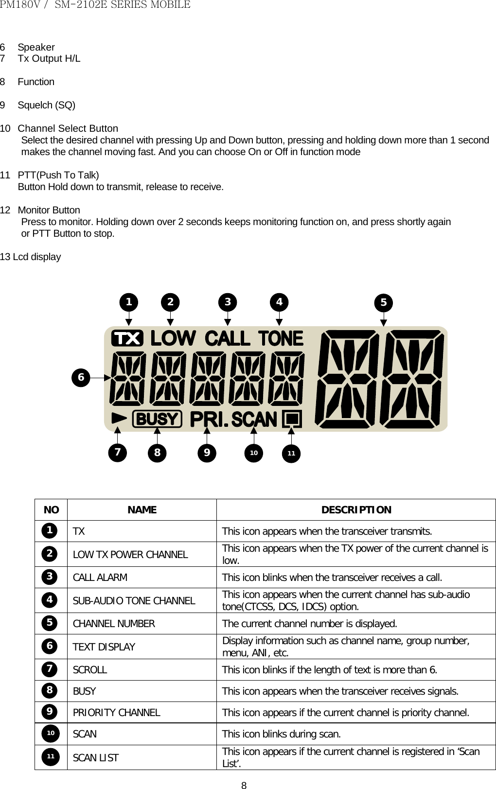
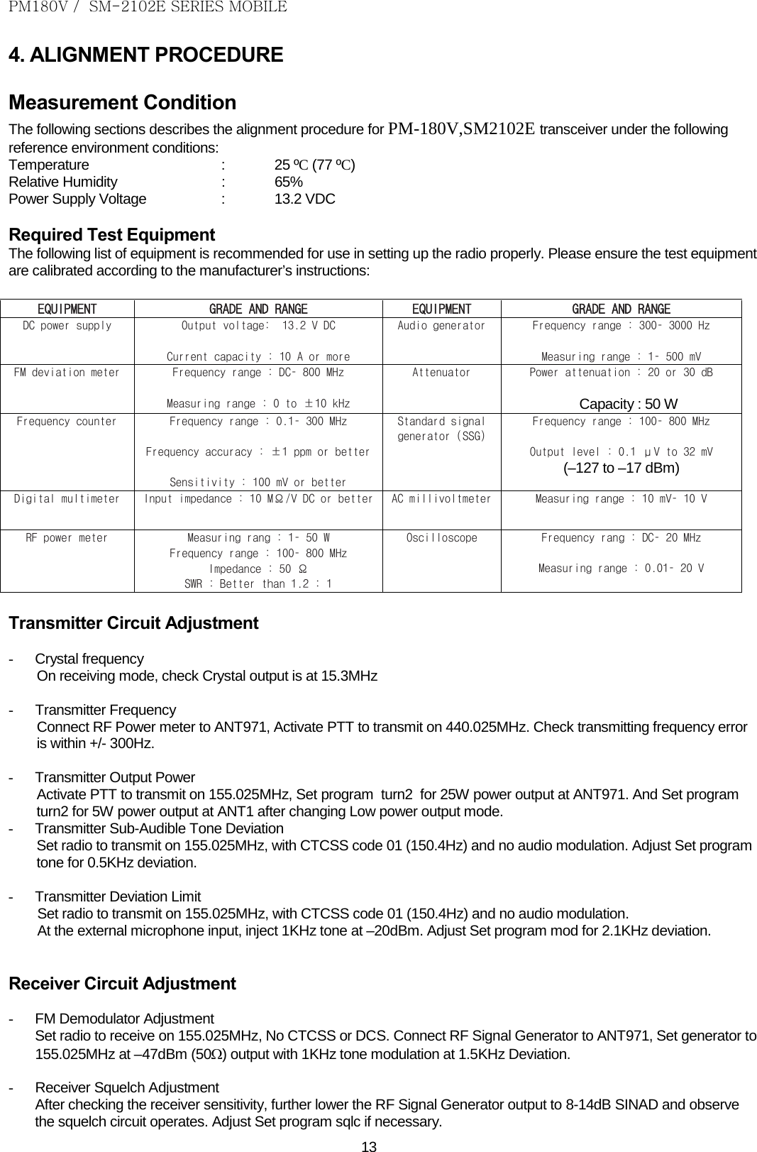
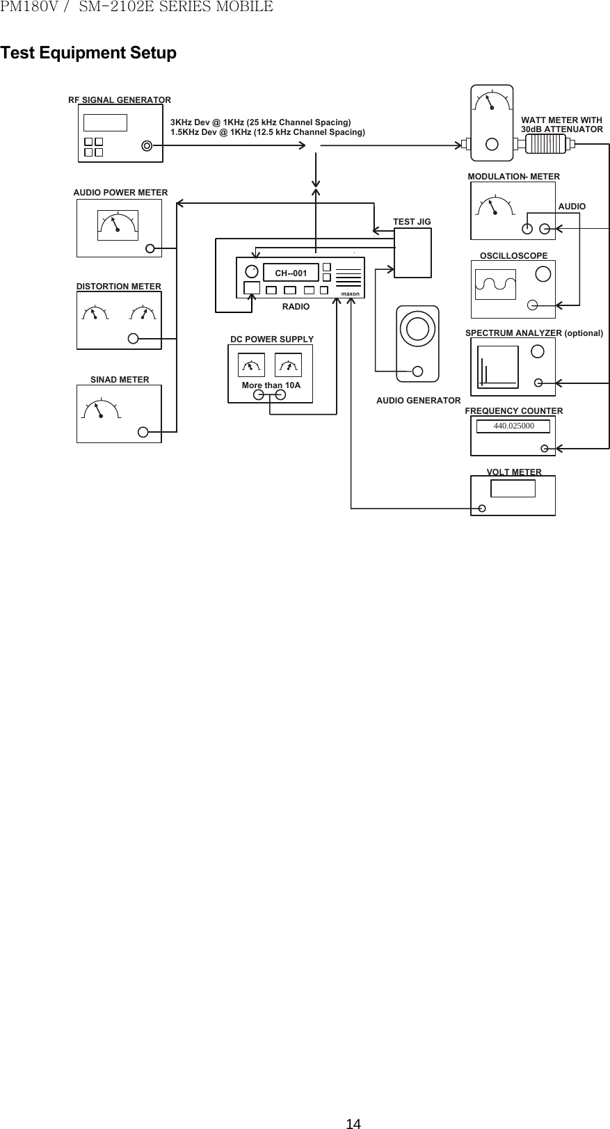
![[텍스트 입력] 4TABLE DES MATIÈRES 1. CARACTÉRISTIQUES 2. DESCRIPTION D'UNITÉ 3. THÉORIE D'EXÉCUTION 4. MARCHE À SUIVRE DE CADRAGE 5. VUE ÉCLATÉE 6. LISTE DES PIÈCES 7. SCHÉMAS DE DISPOSITION ET DE CIRCUIT DE CARTE PCB 8. SCHÉMA FONCTIONNEL](https://usermanual.wiki/Maxon-CIC/SM-2102E/User-Guide-2152595-Page-18.png)
![[텍스트 입력] 5INTRODUCTION Le SM2402E/SM2102E, transmetteurs mobiles de Maxon, emploie la dernière technologie à sa conception et fabrication. Les modèles de VHF et de FRÉQUENCE ULTRA-HAUTE sont PLL (Synthétiseur de Boucle de Verrou de Phase)/contrôlés par microprocesseur, et offrent une alimentation électrique de 5 ou 25 watts avec la capacité de canal 99. Les fonctions Multiples comprenant le Balayage, la signalisation de CTCSS/DCS et 12,5 kilohertz d'interligne de canal sont standard dans ces unités tenues dans la main de grande largeur de bande entièrement programmable. Le SM2402E/SM2102E offre beaucoup de fonctionnalité avancée trouvée dans des Transmetteurs plus chers de Mobile de Terre. 1. CARACTÉRISTIQUES GÉNÉRALITÉS Type de Matériel. . . . . . . . . . . . . . . . . . . . . . . . . . . . . . . . . . . . . . . Stationnaire Bande. . . . . . . . . . . . . . . . . . . . . . . . . . . . . . . . . . . . . . . . . . . . . . . . FRÉQUENCE ULTRA-HAUTE Interligne de la Manche. . . . . . . . . . . . . . . . . . . . . . . . . . . . . . . . . . 12,5 kilohertz programmables Puissance de Sortie de RF. . . . . . . . . . . . . . . . . . . . . . . . . . . . . . . . 25 watts/.5 watt Type de Modulation. . . . . . . . . . . . . . . . . . . . . . . . . . . . . . . . . . . . . . F3E Alimentation Électrique Sonore. . . . . . . . . . . . . . . . . . . . . . . . . . . 6W (Ext. avec 8 ohms) Fréquence Intermédiaire. . . . . . . . . . . . . . . . . . . . . . . . . . . . . . . . . 46,35 Mhz et 450 kilohertz Numéro des Canaux. . . . . . . . . . . . . . . . . . . . . . . . . . . . . . . . . . . . 99 Source de Fréquence. . . . . . . . . . . . . . . . . . . . . . . . . . . . . . . . . . . . . . Synthétiseur Estimation d'Exécution. . . . . . . . . . . . . . . . . . . . . . . . . . . . . . . . . . . . . . Intermittent 90 : 5:5 (Attente : RX : TX) Bloc d'Alimentation. . . . . . . . . . . . . . . . . . . . . . . . . . . . . . . . . . . . . 13,2 volts de nominal de C.C (12-volt, système électrique négatif de véhicule au sol) PLAGE DE TEMPÉRATURES Mémoire . . . . . . . . . . . . . . . . . . . . . . . . . . . . . . . . . . . . . . . . . . . . . . . - De 40° C à + 80° C Opération. . . . . . . . . . . . . . . . . . . . . . . . . . . . . . . . . . . . . . . . . . . . …. - De 30° C à + 60° C CONSOMMATION ACTUELLE De Réserve . . . . . . . . . . . . . . . . . . . . . . . . . . . . . . . . . . . . . . . . . . . . . . < 200 mA Recevez . . . . . . . . . . . . . . . . . . . . . . . . . . . . . . . . . . . . . . . . . . . . . . < 1,0 A Transmettez l'Alimentation Électrique de 25 Watts RF. . . . . . . . . . < 8,0 A BANDES DE FRÉQUENCE RX TX FRÉQUENCE ULTRA-HAUTE: 400,000 - 470,000 Mhz 400,000 - 470,000 Mhz FRÉQUENCE VHF: 136,000 - 174,000 Mhz 136,000 - 174,000 Mhz DIMENSIONS Transmetteur . . . . . . . . . . . . . . . . . . . . .. . . (41mm) H X (139 millimètres) W X (170 millimètres) D POIDS Transmetteur . . . . . . . . . . . . . . . . . . . . . . . . . . . . . . . . . . . . . . . . . . . . . . . 1200g ÉMETTEUR Alimentation Électrique de Transporteur. . . . . . . . . . . . . . .. . . . . . . . . . 25 watts /.5 watt](https://usermanual.wiki/Maxon-CIC/SM-2102E/User-Guide-2152595-Page-19.png)
![[텍스트 입력] 6 ÉCART DE FRÉQUENCE SONORE Sans Modulation de Ton Infra-acoustique : 12,5 kilohertz d'Interligne de la Manche. . . . . . . . . . . . . . . . . . . . . . . . . . . . . . . Maximum ±2.5 kilohertz Avec l'Écart Maximal Infra-acoustique de la Modulation de Ton @ 10 % 12,5 kilohertz. . . . . . . . . . . . . . . . . . . . . . . . . . . . . . . . . . . . . . . . . . . . . . Maximum ±2.5 kilohertz Réaction de Fréquence Sonore. . . . . . . . . . . . . . . . . . . . . . . . . . . . . . Dans +1/-3dB de l'octave 6dB ALIMENTATION ÉLECTRIQUE À CANAL ADJACENT 12,5 kilohertz. . . . . . . . . . . . . . . . . . . . . . . . . . . . . . . . . . . . . . . . . . . . . . < dBc 60 Fausse Émission Conduite. . . . . . . . . . . . . . . . . . . . . . . . . . . . < -36dBm Déformation Sonore d'Émetteur (Sans CTCSS). . . . . . . . . . . . < 5% @ 1 kilohertz Bourdonnement et Bruit : 12,5 kilohertz d'Interligne de la Manche. . . . . . . . . . . . . . . . . . . . . . > DB 40 (avec PSOPH) Stabilité de Chargement. . . . . . . . . . . . . . . . . . . . . . . . . . . . . . . . Aucun oscillateur à ³ 10:1 VSWR toutes les cornières de phase et antenne appropriée Écart Maximal @ 1 kilohertz (Nom. Révélateur +20dB) 12,5 kilohertz d'Interligne de la Manche. . . . . . . . .. . . . . . . . . . . . . . . . . . . Maximum 2,5 kilohertz RÉCEPTEUR Sensibilité (12dB Sinad). . . . . . . . . . . . . . . . . . . . . . . . . . . . . . . . . FRÉQUENCE ULTRA-HAUTE : < dBm -117 (.31μV) Caractéristique d'Amplitude. . . . . . . . . . . . . . . . . . . . . . . . . . . . . . . . < DB ±3 Sélectivité À Canal Adjacent : 12,5 kilohertz d'Interligne de la Manche. . . . . . . . . . . . . . . . . . . . . . . . . . . . . . . >DB 60 Faux Rejet de Réaction. . . . . . . . . . . . . . . . . . . . . . . . . . . . . DB 70 Rejet de Réaction d'Intermodulation. . . . . . . . . . . . . . . . . . . . . . DB 65 Stabilité de Température.. . . . . . . . . . . . . . . . . . . . . . . . . . . . . . . . . . 0,0005% (- 30°C à +60°C) Fausse Émission Conduite et Rayonnée. . . . . . . . . . . . . . . . Selon la FCC et les Règles et les Règlements d'IC Déformation d'AF.. . . . . . . . . . . . . . . . . . . . . . . . . . . . . . . . . . . . . . . . . < 5% Réponse En Fr3quence. . . . . . . . . . . . . . . . . . . . . . . . . . . . . réaction insistée moins sur 6 par dB/octave dedans l'intervalle 300 Hertz - 3000 Hertz Bourdonnement et Bruit de RX : 12,5 kilohertz. . . . . . . . . . . . . . . . . . . . . . . . . . . . . . . . . . . . . . . . . . . . . < DB 40 CARACTÉRISTIQUES DE DÉMODULATION DE TON DE RX TONS INFRA-ACOUSTIQUES - CTCSS Chaîne de Ton. . . . . . . . . . . . . . . . . . . . . . . . . . . . . . . . . . . . . . . . . . . 67 Hertz à 250,3 Hertz Tons Non Standard. . . . . . . . . . . . . . . . . . . . . . . . . . . . . . . . . . . . 50 Hertz à 260 Hertz En Raison de la recherche et développement continue la société se réserve le droit de modifier ces caractéristiques sans préavis.](https://usermanual.wiki/Maxon-CIC/SM-2102E/User-Guide-2152595-Page-20.png)
![[텍스트 입력] 72. DESCRIPTION D'UNITÉ panneau avant 1 3 6 5 NO NOM DESCRIPTION 1 BOUTON DE CONTRÔLE DU VOLUME D'AF SOUS TENSION/HORS TENSION, CONTRÔLE DU VOLUME AFFICHAGE DE FONCTION Suite d'écrans LCD. - Informations sur le canal actuel - Mode de TX/RX - Messages -ANI 3 CLÉS HAUT/BAS Ces clés sont utilisées pour la sélection de canal. 4 CLÉ DE MONITOR/MENU POUSSÉE : SURVEILLEZ LA FONCTION "MARCHE/ARRÊT" PRISE : MODE DE POSITIONNEMENT D'UTILISATEUR "MARCHE/ARRÊT"5 CLÉS PROGRAMMABLES Vous pouvez assigner des fonctions à ces clés dans le programmeur. CONNECTEUR DE MICROPHONE Connectez le microphone à ceci. Ceci est également utilisé pour programmer et copier. 1 Clé de Secours 2 Commutateur de Sous tension/hors tension et de Contrôle du Volume Mettez le transmetteur en marche par le commutateur tournant de sous tension/hors tension et de contrôle du volume dans le sens des aiguilles d'une montre et contrôlez le volume. 3 Antenne de Fouet. Insérez l'embout fileté de l'antenne dans le connecteur sur le transmetteur. Tournez l'antenne dans le sens des aiguilles d'une montre pour l'attacher. 4 Tx/Rx Indiquent le LED (couleur 3) Rouge Sur Transmission la programmation et le clonage écrivent flasher Batterie Faible Vert Sur sous-ton en recevant programmation et clonage lu flasher Sous-ton Différent en recevant Orange Sur Réception, surveillant le clonage](https://usermanual.wiki/Maxon-CIC/SM-2102E/User-Guide-2152595-Page-21.png)
![[텍스트 입력] 8 5 Earphone/MIC Externe et Embase Acceptant Les Jacks De Programmation 6 Orateur 7 Sortie H/L de Tx 8 Fonction 9 Giclement (SQ) 10 Bouton Choisi de la Manche Sélectez le canal désiré en appuyant sur En haut et en bas le bouton. Appuyant Sur et maintenant ce bouton plus longtemps que 1 seconde fera faire un cycle rapidement le transmetteur par les canaux. Ceci peut être tourné "Marche/Arrêt" en mode de fonction 11 PTTS (Poussée À Parler) Bouton Maintenez pour transmettre, relâcher pour recevoir. 12 Surveillez le Bouton Appuyez pour surveiller. Le Maintien plus de 2 secondes garde la fonction de surveillance en fonction. Appuyez de nouveau ou le Bouton de PTTS pour s'arrêter. 13 Écran LCD 1 2 3 4 5678 9 10 11 NO NOM DESCRIPTION TX Cette icône apparaît quand le transmetteur transmet. CANAL FAIBLE D'ALIMENTATION ÉLECTRIQUE DE TX Cette icône apparaît quand l'alimentation électrique de TX du canal actuel est faible. 3 ALARME D'APPEL Cette icône clignote quand le transmetteur reçoit un appel. 4 CANAL INFRA-ACOUSTIQUE DE TON Cette icône apparaît quand le canal actuel a l'option infra-acoustique du ton (CTCSS, DCS, IDCS). 5 NUMÉRO DE CANAL Le numéro de canal actuel est affiché. 6 AFFICHAGE DES TEXTES Affichez l'information telle que le nom de canal, le numéro de groupe, le menu, l'ANI, Etc.](https://usermanual.wiki/Maxon-CIC/SM-2102E/User-Guide-2152595-Page-22.png)
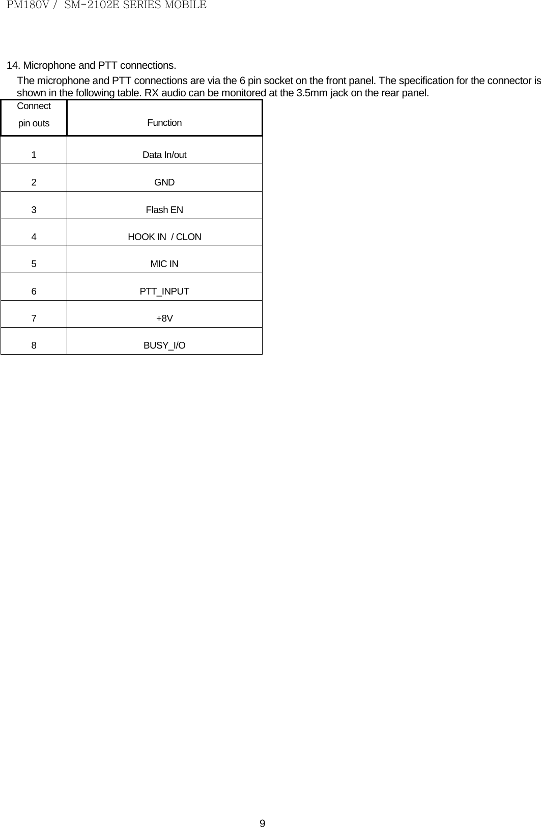
![[텍스트 입력] 9 DÉFILEMENT Cette icône clignote si la longueur du texte est plus de 6. 8 OCCUPÉ Cette icône apparaît quand le transmetteur reçoit des signaux. CANAL PRIORITAIRE Cette icône apparaît si le canal actuel est canal prioritaire. BALAYAGE Cette icône clignote pendant le balayage. LISTE DE BALAYAGE Cette icône apparaît si le canal actuel est enregistré dans la Liste de Balayage de `'. 14. Connexions de Microphone et de PTTS. Le microphone et les connexions de PTTS sont par l'intermédiaire du socket de 6 bornes sur le panneau avant. Le cahier des charges pour le connecteur est affiché dans la table suivante. L'audio de RX peut être surveillé au jack de 3.5mm sur le panneau arrière. Connectez goupillez les sorties Fonction 1 Données In/out 2 LA TERRE 3 EN d'Instantané 4 DANS DE CROCHET/CLON 5 MIC DEDANS 6 PUISSANCE D'ENTRÉE DE PTT_ 7 +8V 8 E/S DE BUSY_](https://usermanual.wiki/Maxon-CIC/SM-2102E/User-Guide-2152595-Page-23.png)