Maxon CIC SM-2102E Mobile radio for vehicle User Manual TABLE OF CONTENTS
Maxon CIC Corp. Mobile radio for vehicle TABLE OF CONTENTS
User Manual
PM180V / SM-2102E SERIES MOBILE
1
PM180 V / SM-2102E
MOBILE TRANSCEIVER
OPERATIONAL DESCRIPTTION

PM180V / SM-2102E SERIES MOBILE
2
WARNINGS
> WARNING! NEVER connect the transceiver to an AC outlet. This may pose a fire hazard or result in
an electric shock.
> NEVER operate the radio transmitter suitable Artificial load connected.
> NEVER connect the transceiver to a power source of more than 16V DC such as a 24V battery.
This connection will ruin the transceiver.
> NEVER cut the DC power cable between the DC Plug and fuse holder. If an incorrect connection
Is made after cutting, the transceiver might be damaged.
Must connect fuse (32V T10AL) before installation.
Replace only with same or equivalent type of use.
> NEVER place the transceiver where normal operation of the vehicle may be hindered or where it could
cause bodily injury.
> NEVER allow children to touch the transceiver.
> NEVER expose the transceiver to rain, snow or any liquids.
> NEVER modify a radio or accessory except as instructed in the service manual, engineering bulletins
or formal communication as this may invalidate any warranty, guarantee or type approval.
> USE the supplied microphone only. Other Microphones have different pin assignments and may
damage the transceiver. (ACC-700 )
> DO NOT use or place the transceiver in areas with temperatures below -30
℃
or above +60
℃
,
In areas subject to direct sunlight, such as the dashboard.
> AVOID operating the transceiver without running The vehicle’s engine. The vehicle’s battery will
quickly run out if the transceiver transmits while the vehicle’s engine OFF
> AVOID placing the transceiver in excessively dusty environments.
> AVOID placing the transceiver against walls. This will obstruct heat dissipation.
> AVOID the use of chemical agents such as benzin or alcohol when cleaning, as they damage
the transceiver surfaces.
> BE CAREFUL ! The transceiver will become hot when operating continuously for long periods.
> DO NOT operate this equipment in environments containing explosive materials or vapour.
One or more of the following statements may be applicable:
FCC WARNING
This equipment generates or users radio frequency energy.
Changes or modifications to this equipment may cause harmful interference unless the modifications are
expressly approved in the instruction manual.
The user could lose the authority to operate this equipment if an unauthorized change or modification is mode.
INFORMATION TO THE DIGITAL DEVICE USER REQUIRED BY THE FCC
This equipment has been tested and found to comply with the limits for a class B digital device, pursuant to part
15 of the FCC rules.
These limits are designed to provide reasonable protection against harmful interference in a residential
installation.
PM180V / SM-2102E SERIES MOBILE
3
This equipment generates, uses and can generate radio frequency energy and, if not installed and used in
accordance with the instructions, may cause harmful interference to radio communications.
However, there is no guarantee that the interference will not occur in a particular installation.
If this equipment does cause harmful interference to radio or television reception, which can be determined to
try to correct the interference by one or more of the following measures:
> Reorient or relocate the receiving antenna.
> Increase the separation between the equipment and receiver.
> Connect the equipment to an outlet on a circuit different form that to which the receiver is connected.
> Consult the dealer for technical assistance.
MANDATORY SAFETY INSTRUCTIONS TO INSTALLERS AND USERS
> Use only manufacturer or dealer supplied antennas.
> Antenna minimum safe distance : 150 cm .
> Antenna gain : 0 dBd referenced to a dipole.
The federal communications commission has adopted a safety standard for human exposure to RF energy
which is below the OSHA limits.
> Antenna mounting : The antenna supplied by the manufacturer or radio dealer must not be mounted at a
location such that during radio transmission, any person or persons can come closer than the above
indicated minimum safe distance to the antenna, i.e.150 cm.
> To comply with current FCC RX exposure limits, the antenna must be installed at or exceeding the minimum
safe distance shown above, and in accordance with the requirements of the antenna manufacturer or supplier.
> Vehicle installation : the antenna can be mounted at the center of a vehicle metal roof or trunk lid, if the
minimum safe distance is observed.
> Base station installation: The antenna should be fixed-mounted on an outdoor permanent structure. RF
exposure compliance must be addressed at the time of installation.
Antenna substitution: Do not substitute any antenna for the one supplied or recommended by the manufacturer
or radio dealer or the manufacturer for further instructions.
You,as the qualified end-user of this radio device must control the exposure conditions of bystanders to ensure
the minimum separation distance is maintained between the antenna and nearby persons for satisfying RF
exposure compliance.
The operation of this transmitter must satisfy the requirements of occupational/ controlled exposure
environment, for work-related use, transmit only when person are at least the minimum distance from the
properly installed, externally mounted antenna.
Transmit only when people outside the vehicle are at least the recommended minimum lateral distance away
from the antenna/vehicle.
Under Industry Canada regulations, this radio transmitter may only operate using an antenna of a type
and maximum (or lesser) gain approved for the transmitter by Industry Canada. To reduce potential radio
interference to other users, the antenna type and its gain should be so chosen that the equivalent
isotropically radiated power (e.i.r.p.) is not more than that necessary for successful communication.
This radio transmitter (identify the device by certification number, or model number if Category II) has
been approved by Industry Canada to operate with the antenna types listed below with the maximum
permissible gain and required antenna impedance for each antenna type indicated. Antenna types not
included in this list, having a gain greater than the maximum gain indicated for that type, are strictly
prohibited for use with this device.
PM180V / SM-2102E SERIES MOBILE
4
TABLE OF CONTENTS
1. SPECIFICATIONS .
2. DESCRIPTION OF UNIT .
3. THEORY OF OPERATION .
4. ALIGNMENT PROCEDURE .
5. EXPLODED VIEW .
6. PARTS LIST .
7. PCB LAYOUT AND CIRCUIT DIAGRAMS .
8. BLOCK DIAGRAM .
PM180V / SM-2102E SERIES MOBILE
5
INTRODUCTION
The PM-180V,SM2102E of mobile radios from Maxon, utilizes the latest technology in its design and
manufacturing. Both the VHF and UHF models are PLL (Phase Lock Loop Synthesizer)
/ microprocessor controlled, and offer 5 or 25 watts of power with 99 channel capability.
Multiple functions including Scan, CTCSS / DCS signaling and 12.5 & 25 kHz
channel spacing are standard in these fully programmable wide bandwidth handheld units.
The PM-180U,SM2402E offers many advanced features found in more expensive Land Mobile Radios.
1.SPECIFICATIONS
GENERAL
Equipment Type . . . . . . . . . . . . . . . . . . . . . . . . . . . . . . . . . . . . . . . Stationary
Band . . . . . . . . . . . . . . . . . . . . . . . . . . . . . . . . . . . . . . . . . . . . . . . . . VHF
Channel Spacings . . . . . . . . . . . . . . . . . . . . . . . . . . . . . . . . . . . . . . 12.5 kHz, 25 kHz programmable
RF Output Power . . . . . . . . . . . . . . . . . . . . . . . . . . . . . . . . . . . . . . 25 watt / , 5 watt
Modulation Type . . . . . . . . . . . . . . . . . . . . . . . . . . . . . . . . . . . . . . . F3E
Audio Power . . . . . . . . . . . . . . . . . . . . . . . . . . . . . . . . . . . . . . . . . . 6W (Ext with 8 ohm)
Intermediate Frequency . . . . . . . . . . . . . . . . . . . . . . . . . . . . . . . . . 46.35 MHz & 450 kHz
Number of Channels. . . . . . . . . . . . . . . . . . . . . . . . . . . . . . . . . . . . 99
Frequency Source . . . . . . . . . . . . . . . . . . . . . . . . . . . . . . . . . . . . . . Synthesizer
Operation Rating . . . . . . . . . . . . . . . . . . . . . . . . . . . . . . . . . . . . . . Intermittent
14 min : 1 min : 1 min (Standby: RX: TX)
Power Supply. . . . . . . . . . . . . . . . . . . . . . . . . . . . . . . . . . . . . . . . . 13.2 volts DC nominal (12-volt, negative ground
vehicle electrical system)
TEMPERATURE RANGE
Storage . . . . . . . . . . . . . . . . . . . . . . . . . . . . . . . . . . . . . . . . . . . . . . . From - 40° C to + 80° C
Operating. . . . . . . . . . . . . . . . . . . . . . . . . . . . . . . . . . . . . . . . . . . . . From - 30° C to + 60° C
CURRENT CONSUMPTION
Standby . . . . . . . . . . . . . . . . . . ………... . . . . . . . . . . . . . . . . . . . < 200 mA
Receive . . . . . . . . . . . . . . . . . . . . ………………….. . . . . . . . . . . < 1.0 A
Transmit 25 Watt RF Power . . . . . . . . . . . . . . . . . . . . . . . . . . . . < 8.0 A
FREQUENCY BANDS RX TX
VHF: 136.000 - 174.000 MHz 136.000 - 174.000 MHz
DIMENSIONS
Radio . . . . . . . . . . . . . . . . . . . . . . . . . . . . . . . . . . . . . . . . . . . . . . . . (41mm)H x (139 mm)W x (170 mm)D
WEIGHT
Radio . . . . . . . . . . . . . . . . . . . . . . . . . . . . . . . . . . . . . . . . . . . . . . . 1200g
TRANSMITTER
Carrier Power . . . . . . . . . . . . . . . . . . . . . . . . . . . . . . . . . . . . . . . . . 25 watt / , 5 watt
AUDIO FREQUENCY DEVIATION
Without Subaudio Tone Modulation:
25 kHz Channel Spacing . . . . . . . . . . . . . . . . . . . . . . . . . . . . . . . . Max. ±5.0 kHz
12.5 kHz Channel Spacing . . . . . . . . . . . . . . . . . . . . . . . . . . . . . . . Max. ±2.5 kHz
With Subaudio Tone Modulation @ 10 % Peak Deviation
25 kHz Channel Spacing . . . . . . . . . . . . . . . . . . . . . . . . . . . . . . . . Max. ±5.0 kHz
12.5 kHz . . . . . . . . . . . . . . . . . . . . . . . . . . . . . . . . . . . . . . . . . . . . . . Max. ±2.5 kHz
Audio Frequency Response . . . . . . . . . . . . . . . . . . . . . . . . . . . . . . Within +1/-3dB of 6dB octave
ADJACENT CHANNEL POWER
25 kHz . . . . . . . . . . . . . . . . . . . . . . . . . . . . . . . . . . . . . . . . . . . . . . . < 70 dBc
12.5 kHz . . . . . . . . . . . . . . . . . . . . . . . . . . . . . . . . . . . . . . . . . . . . . . < 60 dBc
Conducted Spurious Emission. . . . . . . . . . . . . . . . . . . . . . . . . . . . < -36dBm
PM180V / SM-2102E SERIES MOBILE
6
Transmitter Audio Distortion (Without CTCSS) . . . . . . . . . . . . < 5% @ 1 kHz
Hum & Noise:
12.5 kHz Channel Spacing . . . . . . . . . . . . . . . . . . . . . . . . . . . . . . . > 40 dB (with PSOPH)
25 kHz Channel Spacing . . . . . . . . . . . . . . . . . . . . . . . . . . . . . . . . > 40 dB (with no PSOPH)
Load Stability . . . . . . . . . . . . . . . . . . . . . . . . . . . . . . . . . . . . . . . . . No osc at ³ 10:1 VSWR all phase angles
and suitable antenna
Peak Deviation @ 1 kHz (Nom. Dev +20dB)
25 kHz Channel Spacing . . . . . . . . . . . . . . . . . . . . . . . . . . . . . . . . Max. 5.0 kHz
12.5 kHz Channel Spacing . . . . . . . . . . . . . . . . . . . . . . . . . . . . . . . Max. 2.5 kHz
RECEIVER
Sensitivity (12dB Sinad) . . . . . . . . . . . . . . . . . . . . . . . . . . . . . . . . . VHF: < -117 dBm(.31μV)
Amplitude Characteristic. . . . . . . . . . . . . . . . . . . . . . . . . . . . . . . . < ±3 dB
Adjacent Channel Selectivity:
25 kHz Channel Spacing . . . . . . . . . . . . . . . . . . . . . . . . . . . . . . . . >70 dB
12.5 kHz Channel Spacing . . . . . . . . . . . . . . . . . . . . . . . . . . . . . . . >60 dB
Spurious Response Rejection. . . . . . . . . . . . . . . . . . . . . . . . . . . . . 70 dB
Intermodulation Response Rejection . . . . . . . . . . . . . . . . . . . . . . 65 dB
Temperature Stability. . . . . . . . . . . . . . . . . . . . . . . . . . . . . . . . . . . 0.0005% (-30°C to +60°C)
Conducted and Radiated Spurious Emission. . . . . . . . . . . . . . . . Per FCC and IC Rules and Regulations
AF Distortion. . . . . . . . . . . . . . . . . . . . . . . . . . . . . . . . . . . . . . . . . . < 5%
Frequency Response . . . . . . . . . . . . . . . . . . . . . . . . . . . . . . . . . . . . 6 dB/octave de-emphasized response in
the range 300 Hz - 3000 Hz
RX Hum & Noise:
25 kHz . . . . . . . . . . . . . . . . . . . . . . . . . . . . . . . . . . . . . . . . . . . . . . . < 40 dB
12.5 kHz . . . . . . . . . . . . . . . . . . . . . . . . . . . . . . . . . . . . . . . . . . . . . < 40 dB
RX TONE DEMODULATION CHARACTERISTICS
SUBAUDIO TONES - CTCSS
Tone Range . . . . . . . . . . . . . . . . . . . . . . . . . . . . . . . . . . . . . . . . . . . 67 Hz to 250.3 Hz
Non-Standard Tones . . . . . . . . . . . . . . . . . . . . . . . . . . . . . . . . . . . . 50 Hz to 260 Hz
Due to continuing research and development the company reserves the right to alter these
specifications without prior notice.
PM180V / SM-2102E SERIES MOBILE
7
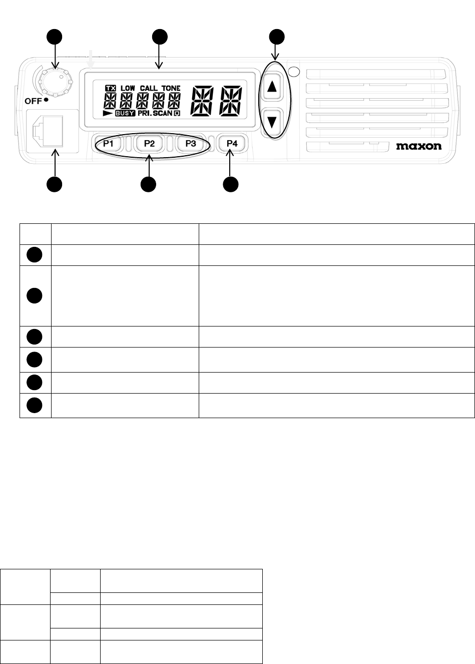
2. DESCRIPTION OF UNIT
Front Panel
1
2
3
6
5
4
NO NAME DESCRIPTION
1
AF VOLUME CONTROL KNOB POWER ON/OFF, VOLUME CONTROL
2
FUNCTION DISPLAY
LCD displays followings.
- Information about the current channel
- TX/RX Status
- Messages
- ANI
3
UP/DOWN KEYS These keys are used for channel selection.
4
MONITOR/MENU KEY
PUSH: MONITOR FUNCTION ON/OFF
HOLD: USER SET MODE ON/OFF
5
PROGRAMMABLE KEYS You can assign functions to these keys in programmer.
6
MICROPHONE CONNECTOR
Connect the microphone to this.
This is also used for programming and cloning.
1 Emergency Key
2 Power on / off and Volume Control Switch
Turn the transceiver on by rotating power on / off and volume control switch clockwise and control the volume.
3 Whip Antenna.
Insert the threaded end of the antenna into the connector on top of the radio. Rotate the
antenna clockwise to fasten it.
4 Tx / Rx Indicate LED (3 colour’s)
Red On
Transmitting
programming and cloning write
flashing
Low battery
Green On
sub-tone when receiving
programming and cloning read
flashing
Different sub-tone when receiving
Orange On
Receiving, monitoring cloning
5 External Earphone/MIC and Programming Jack Socket
PM180V / SM-2102E SERIES MOBILE
8
6 Speaker
7 Tx Output H/L
8 Function
9 Squelch (SQ)
10 Channel Select Button
Select the desired channel with pressing Up and Down button, pressing and holding down more than 1 second
makes the channel moving fast. And you can choose On or Off in function mode
11 PTT(Push To Talk)
Button Hold down to transmit, release to receive.
12 Monitor Button
Press to monitor. Holding down over 2 seconds keeps monitoring function on, and press shortly again
or PTT Button to stop.
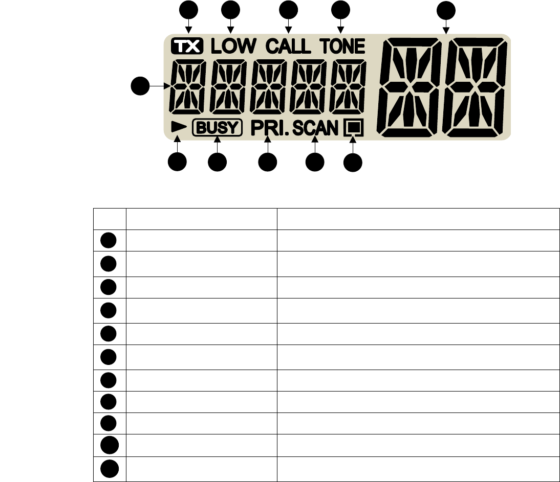
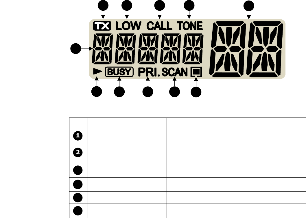
13 Lcd display
1 2 3 4 5
6
789
10 11
NO NAME DESCRIPTION
1
TX This icon appears when the transceiver transmits.
2
LOW TX POWER CHANNEL
This icon appears when the TX power of the current channel is
low.
3
CALL ALARM This icon blinks when the transceiver receives a call.
4
SUB-AUDIO TONE CHANNEL
This icon appears when the current channel has sub-audio
tone(CTCSS, DCS, IDCS) option.
5
CHANNEL NUMBER The current channel number is displayed.
6
TEXT DISPLAY
Display information such as channel name, group number,
menu, ANI, etc.
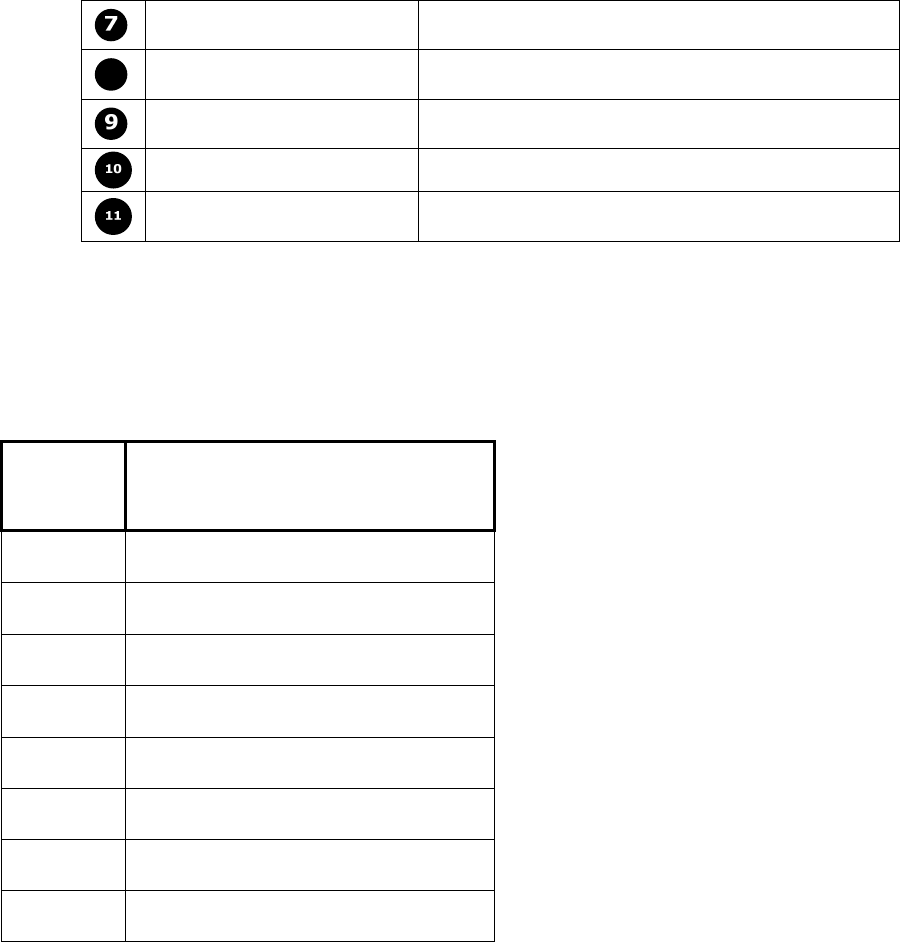
7
SCROLL This icon blinks if the length of text is more than 6.
8
BUSY This icon appears when the transceiver receives signals.
9
PRIORITY CHANNEL This icon appears if the current channel is priority channel.
10
SCAN This icon blinks during scan.
11
SCAN LIST
This icon appears if the current channel is registered in ‘Scan
List’.

PM180V / SM-2102E SERIES MOBILE
9
14. Microphone and PTT connections.
The microphone and PTT connections are via the 6 pin socket on the front panel. The specification for the connector is
shown in the following table. RX audio can be monitored at the 3.5mm jack on the rear panel.
Connect
pin outs Function
1 Data In/out
2 GND
3 Flash EN
4 HOOK IN / CLON
5 MIC IN
6 PTT_INPUT
7 +8V
8 BUSY_I/O
PM180V / SM-2102E SERIES MOBILE
10
3. THEORY OF OPERATION
INTRODUCTION
PM-180V,SM2102E are 99 channel portable FM transceiver constructed with a microprocessor controlled,
temperature compensated Phase Locked Loop (PLL) frequency synthesizer. The radio features
a double conversion receiver and a direct FM transmitter modulator. A special integrated circuit provides
support to sub-audible signaling (CTCSS & DCS) and most of the receiving parts are switched off periodically
in the power saver mode to reduce battery current drain during standby.
The Block Diagram RF and Control Circuit Diagrams for PM-180V,SM2102E shall be used in associate
with the following circuit description.
CIRCUIT DESCRIPTIONS
1) PHASE-LOCK LOOP (PLL) CIRCUIT
* REFERENCE OSCILLATOR
The reference oscillator in the Frequency Synthesizer IC601, uses the TCXO631 as a stabilized
source of 15.3MHz. The reference oscillator frequency drives the divider in the Frequency synthesizer
to produce a comparison frequency.
This comparison frequency is selected by decoding the first three bits of the data input
from microcomputer.
* PROGRAMMABLE DIVIDER
The programmable divider in IC601 divides the VCO output . It consists of a two-modulus pre-scalar
with a 7bit control register followed by a 11-bit internal programmable divider. The overall division ratio is
selected by a single 19-bit word located on the serial data bus.
* PHASE COMPARATOR
The digital-type phase comparator in IC601 compares the divided VCO frequency with the comparison
frequency. It generates a correction voltage that is applied to a low-pass filter consisting of R621-
R623,R624, C617,C618,
C620. This voltage is applied to the VCO circuit. The phase comparator also provides the lock detect
signal .
* VCO CIRCUIT
The VCO circuits contains a separate RX VCO (Q521,D511,D512) and TX VCO
(Q541,D531,D532,D533,D534). The oscillated signal is amplified at the buffer amplifiers
(Q571,Q572)and is then applied to the T/R switch (D901,D902). Then the Receive 1st LO (Rx) signal is
applied to the 1st mixer (Q801)and the transmit (Tx) signal to the amplifier circuit ( Q901).
A portion of the signal from the buffer amplifier (Q571) is fed back to the PLL IC) via the doubler circuit
(Q591) as the comparison signal.
2) TRANSMITTER
* MIC AMP CIRCUIT
Voice signal from the microphone are applied to microphone amplifier IC305. IC306 is configured as
a low-pass filter that has a 6dB/oct response between 300Hz and 3kHz. The microphone audio signal
is amplified by IC305-A, with R351 and C347 on the output providing pre-emphasis.
The microphone audio signal is then fed to switch IC304 on pin 4 and the switched output signal
is on pin 3. This signal is then applied to high-pass filter IC306- D,-C which attenuates frequencies
in the Call Guard (CTCSS/DTCS) range. This is the same filter used for receive audio filtering.
The signal is then fed to IC306-B and IC306-A which provide buffering and amplification.
PM180V / SM-2102E SERIES MOBILE
11
Deviation limiting is then provided by level controller IC307. The input to this device is pin 16 and
the output is pin 15. The signal is then fed to splatter filter IC303-A and switch IC304-C. The input is
on pin 8 and the output is on pin 9. The modulation signal is then applied to the PLL circuit as “MOD”.
* VCO AND AMPLIFIER
The VCO signal output is switched by diodes D901 and then amplified by Q901, Q902, Q911,Q912 and
then fed to power amplifier Q931.
* POWER AMPLIFIER CIRCUIT
Q931 is provided with approximately 13.2 VDC power source.
The power detector circuit D991 detects the transmit power output level and converts it into DC
voltage.The output voltage is at a minimum level when the antenna impedance is matched with 50 Ω
and is increased when it is mismatched. The detected voltage is applied to the differential amplifier
IC761, and the “TURN_2” signal from the D/A converter controlled by the MCU is applied to the other
input for reference. When antenna impedance is mismatched, the detected voltage exceeds the power
setting voltage. Then the output voltage of the differential amplifier IC761 controls the input bias
voltage of the drive ; Q911,Q912,Q931
The signals from Q931 is supplied through a low-pass filter made up of L973, L974, L975 and
C975-C979, C981 to antenna switch D971 then applied to Antenna Connector.
3) RECEIVER
* ANT SWITCHING CIRCUIT
Signals from antenna connector fed to the antenna switching circuit . In receive mode, D971 is turned
off, which isolates the antenna from the transmitter circuit, so that the incoming signals are fed to the RF
amplifier through L850.
* RF AMPIFIER CIRCUIT
The signal, from the switching circuit, is fed to the RF amplifier Q831 through a band pass filter made up
of coil, varicap diode and capacitor.
* FIRST MIXER CIRCUIT
The amplified signals are fed to Gate 2 of the first mixer Q801 through C821.
First local oscillator signal is supplied to Gate 1 of Q801 from the VCO circuit through C813 to convert
the RF signal into the 46.35MHz first IF signal.
* IF CIRCUIT
The first IF signal from Q801 is fed to the matched pair crystal filter, MCF801, then the signal is amplified in
Q646. This signal is fed to IC641, which is composed of the second mixer, limiter amplifier, quadrature
detector and active filter circuit.
The second local oscillator at 45.9 MHz is produced at the PLL circuit by tripling it’s reference frequency
15.3 MHz.and is fed to the second mixer with the first IF signals to convert into 450kHz second IF signals.
The second IF signals leave through pin 3,and are fed to external ceramic filters FL641,FL642 then
back to IC641 (pin 5) to be amplified and detected. The detected AF signals are output from pin 9.
* Squelch (mute) CIRCUIT
The squelch circuit switches off the power amplifier when no audio signal is present. The squelch circuit
consists of a 16 kHz band pass filter and a noise detector circuit.
* Speaker Audio Amplifier CIRCUIT
After signal detection and audio filtering, the low level audio is returned to the RF circuit via SWR101.
This is then routed to Pin 1 of IC1, (TDA1517), to provide speaker audio. IC1 is enabled by a logic high
applied to Q301 which in turn enables Q300, applying power to Pin 5 of IC1.The audio signal
from IC641, pin 9 is applied to AF amplifier IC305-B and then fed to pin 1 of AF switching circuit
IC304-A . The switched output signal on IC304-A, pin 2 is then applied to high-pass filter IC306-D,
IC306-C. The cut-off frequency of this filter is controlled by the “RX AUDIO FILTER” line. The filtered
output signal on IC306-C, pin 8 is applied to limiter IC306-B and buffer IC306-A. De-emphasis is
PM180V / SM-2102E SERIES MOBILE
12
rovided by R414 and C369. The audio signal is then applied to pin 16 of level controller IC307. This
device allows the CPU to control the speaker volume level(ATE mode).The level controlled signal is fed
out of IC307 on pin 15 and applied to low-pass filter IC303-A. It is then applied to AF switching circuit
IC304-D on pin 11, and the switched output is on pin 10. This signal is buffered by IC303-B and then
amplified by AF amplifier IC1 to provide driveto the speaker.

PM180V / SM-2102E SERIES MOBILE
13
4. ALIGNMENT PROCEDURE
Measurement Condition
The following sections describes the alignment procedure for PM-180V,SM2102E transceiver under the following
reference environment conditions:
Temperature : 25 ºC (77 ºC)
Relative Humidity : 65%
Power Supply Voltage : 13.2 VDC
Required Test Equipment
The following list of equipment is recommended for use in setting up the radio properly. Please ensure the test equipment
are calibrated according to the manufacturer’s instructions:
EQUIPMENT
GRADE AND RANGE
EQUIPMENT
GRADE AND RANGE
DC power supply
Output voltage: 13.2 V DC
Current capacity : 10 A or more
Audio generator
Frequency range : 300–3000 Hz
Measuring range : 1–500 mV
FM deviation meter
Frequency range : DC–800 MHz
Measuring range : 0 to ±10 kHz
Attenuator
Power attenuation : 20 or 30 dB
Capacity : 50 W
Frequency counter
Frequency range : 0.1–300 MHz
Frequency accuracy : ±1 ppm or better
Sensitivity : 100 mV or better
Standard signal
generator (SSG)
Frequency range : 100–800 MHz
Output level : 0.1 μV to 32 mV
(–127 to –17 dBm)
Digital multimeter
Input impedance : 10 MΩ/V DC or better
AC millivoltmeter
Measuring range : 10 mV–10 V
RF power meter
Measuring rang : 1– 50 W
Frequency range : 100–800 MHz
Impedance : 50 Ω
SWR : Better than 1.2 : 1
Oscilloscope
Frequency rang : DC–20 MHz
Measuring range : 0.01–20 V
Transmitter Circuit Adjustment
- Crystal frequency
On receiving mode, check Crystal output is at 15.3MHz
- Transmitter Frequency
Connect RF Power meter to ANT971, Activate PTT to transmit on 440.025MHz. Check transmitting frequency error
is within +/- 300Hz.
- Transmitter Output Power
Activate PTT to transmit on 155.025MHz, Set program turn2 for 25W power output at ANT971. And Set program
turn2 for 5W power output at ANT1 after changing Low power output mode.
- Transmitter Sub-Audible Tone Deviation
Set radio to transmit on 155.025MHz, with CTCSS code 01 (150.4Hz) and no audio modulation. Adjust Set program
tone for 0.5KHz deviation.
- Transmitter Deviation Limit
Set radio to transmit on 155.025MHz, with CTCSS code 01 (150.4Hz) and no audio modulation.
At the external microphone input, inject 1KHz tone at –20dBm. Adjust Set program mod for 2.1KHz deviation.
Receiver Circuit Adjustment
- FM Demodulator Adjustment
Set radio to receive on 155.025MHz, No CTCSS or DCS. Connect RF Signal Generator to ANT971, Set generator to
155.025MHz at –47dBm (50Ω) output with 1KHz tone modulation at 1.5KHz Deviation.
- Receiver Squelch Adjustment
After checking the receiver sensitivity, further lower the RF Signal Generator output to 8-14dB SINAD and observe
the squelch circuit operates. Adjust Set program sqlc if necessary.
PM180V / SM-2102E SERIES MOBILE
14
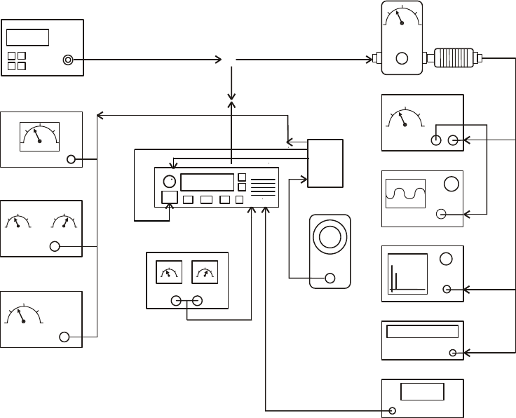
Test Equipment Setup
440.025000
WATT METER WITH
30dB ATTENUATOR
AUDIO
MODULATION- METER
AUDIO GENERATOR
DC POWER SUPPLY
RADIO
OSCILLOSCOPE
SPECTRUM ANALYZER (optional)
FREQUENCY COUNTER
VOLT METER
AUDIO POWER METER
SINAD METER
DISTORTION METER
RF SIGNAL GENERATOR
3KHz Dev @ 1KHz (25 kHz Channel Spacing)
1.5KHz Dev @ 1KHz (12.5 kHz Channel Spacing)
TEST JIG
More than 10A
maxon
CH--001
[텍스트 입력]
1
SM2402E / SM2102E
TRANSMETTEUR MOBILE
DESCRIPTION OPÉRATIONNELLE

[텍스트 입력]
2
AVERTISSEMENTS
> AVERTISSEMENT ! Ne connectez jamais le transmetteur à une Prise secteur. Ceci peut poser un risque
d'incendie ou un résultat dans une décharge électrique.
> N'actionnez jamais le chargement artificiel approprié d'émetteur de transmetteur connecté.
> Ne connectez jamais le transmetteur à une source d'énergie de plus que C.C 16V tel qu'une batterie 24V. Cette
connexion ruinera le transmetteur.
> Ne coupez jamais le câble d'alimentation de C.C entre la fiche de C.C et le support de fusible, car ceci
endommagera le transmetteur.
> CONNECTEZ le fusible (32V T10AL) avant l'installation. Le Fusible peut seulement être remplacé par le même ou
le type équivalent.
> Ne mettez jamais le transmetteur où le fonctionnement normal du véhicule peut être gêné ou où il pourrait
entraîner la blessure corporelle.
> Ne permettez jamais aux enfants de toucher le transmetteur.
> N'exposez jamais le transmetteur à la pluie, à la neige ou à aucun liquide.
> Ne modifiez jamais un transmetteur ou un accessoire à moins que comme indiqué dans le manuel, les bulletins
d'ingénierie ou la transmission formelle en tant que ceci puissent infirmer n'importe quelle garantie, garantie ou
homologation.
> UTILISEZ le microphone fourni (ACC-700B) seulement. D'Autres Microphones ont différentes affectations de
broche et peuvent endommager le transmetteur.
> N'utilisez pas ou ne mettez pas le transmetteur dans les zones avec les températures ci-dessous -30Ԩ ou au-
dessus de +60Ԩ, ou dans les zones sujet à la lumière du soleil directe, telle que le tableau de bord d'un véhicule.
> AVOID actionnant le transmetteur sans engine de véhicule de fonctionnement. La batterie du véhicule sera
rapidement vidée de son alimentation électrique si le transmetteur transmet tandis que l'engine de véhicule est
éteinte.
> AVOID mettant le transmetteur dans les environnements excessivement poussiéreux.
> AVOID mettant le transmetteur contre des murs. Ceci obstruera la dissipation thermique.
> ÉVITEZ l'utilisation des agents chimiques tels que la Benzine ou l'Alcool en nettoyant, comme ils endommagent
les surfaces du transmetteur.
> PRENEZ SOIN ! Le transmetteur deviendra chaud quand fonctionnant continuellement pendant de longues
périodes.
> N'actionnez pas ce matériel dans les environnements contenant les matériaux explosifs ou la vapeur.
Un ou plusieurs des déclarations suivantes peuvent s'appliquer :
AVERTISSEMENT DE FCC
Ce matériel produit ou utilise de l'énergie de fréquence de transmetteur.
Les Modifications ou les modifications à ce matériel peuvent entraîner l'interférence néfaste à moins que les
modifications soient expressément approuvées du manuel d'instruction.
L'utilisateur pourrait détruire l'autorité pour actionner ce matériel si une modification ou une modification non
autorisée est apportée.
L'INFORMATION À L'UTILISATEUR D'APPAREIL NUMÉRIQUE REQUIS PAR LA FCC
Ce matériel a été testé et avéré pour être conforme aux limites pour un appareil numérique de la classe B,
conformément à la partie 15 des Réglementations de la FCC.
Ces limites sont conçues pour assurer la protection raisonnable contre l'interférence néfaste dans une installation
résidentielle.
Les utilisations de Ce matériel et peuvent produire de l'énergie de fréquence de transmetteur. Sinon installé et
utilisé selon les instructions, peut entraîner l'interférence néfaste aux transmissions de transmetteur. Cependant, il
n'y a aucune garantie que l'interférence ne se produira pas dans une installation particulière.
[텍스트 입력]
3
Si ce matériel entraîne l'interférence néfaste à la réception de transmetteur ou d'émissions télévisées, qui peut être
déterminée pour essayer de corriger l'interférence par un ou plusieurs des mesures suivantes :
> Réorientez ou replacez l'antenne de réception.
> Augmentez la distance de la séparation entre le matériel et le récepteur.
> Connectez le matériel à un débouché ou à un circuit différent de celui auquel le récepteur est connecté.
> Consultez le marchand de transmetteur pour l'assistance technique.
INSTRUCTIONS DE SÉCURITÉ OBLIGATOIRES AUX INSTALLATEURS ET AUX UTILISATEURS
> Utilisez seulement le constructeur ou les antennes fournies par distributeur.
> L'Antenne doit être installée à une distance de sécurité minimum de 150 cm .
> Gain d'Antenne : 0 dBd référencés à un dipôle.
La Commission Fédérale des Communications a adopté une norme de sécurité pour l'exposition humaine à
l'énergie de RF qui est ci-dessous les limites d'OSHA.
> Support d'Antenne : L'antenne fournie par le marchand de constructeur ou de transmetteur ne doit pas être
montée à un emplacement tels que pendant la transmission de transmetteur, toute personne ou les personnes
peut venir plus étroitement que la distance de sécurité minimum ci-dessus indiquée à l'antenne, c.-à-d., 120 cm (4
pieds).
> Pour se conformer aux limites d'exposition actuelles de la FCC RX, l'antenne doit être installée ou dépassant la
distance de sécurité minimum affichée ci-dessus, et selon aux conditions du constructeur ou du fournisseur
d'antenne.
> Installation de Véhicule : l'antenne peut être montée au centre du toit en métal d'un véhicule ou du couvercle de
joncteur réseau, si on observe la distance de sécurité minimum.
> Installation de station de Base : L'antenne devrait fixe-être montée sur une structure permanente extérieure. La
conformité d'exposition de RF doit être adressée au moment de l'installation.
Substitution d'Antenne : Ne substituez aucune antenne à celle fournie ou recommandée par le marchand de
constructeur ou de transmetteur.
Vous, en tant qu'utilisateur qualifié de ce dispositif de transmetteur, devez être dans la conformité d'exposition de
RF, en contrôlant l'exposition de RF aux spectateurs en assurant la distance minimum de séparation est mis à jour
entre eux et l'antenne.
L'exécution de cet émetteur doit répondre aux exigences de professionnel/a contrôlé l'environnement d'exposition,
pour l'usage lié au travail.
Transmettez seulement quand les gens en dehors du véhicule sont au moins la distance transversale minimum
recommandée à partir de l'antenne/du véhicule.
[텍스트 입력]
4
TABLE DES MATIÈRES
1. CARACTÉRISTIQUES
2. DESCRIPTION D'UNITÉ
3. THÉORIE D'EXÉCUTION
4. MARCHE À SUIVRE DE CADRAGE
5. VUE ÉCLATÉE
6. LISTE DES PIÈCES
7. SCHÉMAS DE DISPOSITION ET DE CIRCUIT DE CARTE PCB
8. SCHÉMA FONCTIONNEL
[텍스트 입력]
5
INTRODUCTION
Le SM2402E/SM2102E, transmetteurs mobiles de Maxon, emploie la dernière
technologie à sa conception et fabrication. Les modèles de VHF et de
FRÉQUENCE ULTRA-HAUTE sont PLL (Synthétiseur de Boucle de Verrou de
Phase)/contrôlés par microprocesseur, et offrent une alimentation électrique de 5
ou 25 watts avec la capacité de canal 99.
Les fonctions Multiples comprenant le Balayage, la signalisation de CTCSS/DCS
et 12,5 kilohertz d'interligne de canal sont standard dans ces unités tenues dans
la main de grande largeur de bande entièrement programmable.
Le SM2402E/SM2102E offre beaucoup de fonctionnalité avancée trouvée dans des
Transmetteurs plus chers de Mobile de Terre.
1. CARACTÉRISTIQUES
GÉNÉRALITÉS
Type de Matériel. . . . . . . . . . . . . . . . . . . . . . . . . . . . . . . . . . . . . . . Stationnaire
Bande. . . . . . . . . . . . . . . . . . . . . . . . . . . . . . . . . . . . . . . . . . . . . . . . FRÉQUENCE ULTRA-HAUTE
Interligne de la Manche. . . . . . . . . . . . . . . . . . . . . . . . . . . . . . . . . . 12,5 kilohertz programmables
Puissance de Sortie de RF. . . . . . . . . . . . . . . . . . . . . . . . . . . . . . . . 25 watts/.5 watt
Type de Modulation. . . . . . . . . . . . . . . . . . . . . . . . . . . . . . . . . . . . . . F3E
Alimentation Électrique Sonore. . . . . . . . . . . . . . . . . . . . . . . . . . . 6W (Ext. avec 8 ohms)
Fréquence Intermédiaire. . . . . . . . . . . . . . . . . . . . . . . . . . . . . . . . . 46,35 Mhz et 450 kilohertz
Numéro des Canaux. . . . . . . . . . . . . . . . . . . . . . . . . . . . . . . . . . . . 99
Source de Fréquence. . . . . . . . . . . . . . . . . . . . . . . . . . . . . . . . . . . . . . Synthétiseur
Estimation d'Exécution. . . . . . . . . . . . . . . . . . . . . . . . . . . . . . . . . . . . . . Intermittent
90 : 5:5 (Attente : RX : TX)
Bloc d'Alimentation. . . . . . . . . . . . . . . . . . . . . . . . . . . . . . . . . . . . . 13,2 volts de nominal de
C.C (12-volt, système
électrique négatif de véhicule
au sol)
PLAGE DE TEMPÉRATURES
Mémoire . . . . . . . . . . . . . . . . . . . . . . . . . . . . . . . . . . . . . . . . . . . . . . . - De 40° C à + 80° C
Opération. . . . . . . . . . . . . . . . . . . . . . . . . . . . . . . . . . . . . . . . . . . . …. - De 30° C à + 60° C
CONSOMMATION ACTUELLE
De Réserve . . . . . . . . . . . . . . . . . . . . . . . . . . . . . . . . . . . . . . . . . . . . . . < 200 mA
Recevez . . . . . . . . . . . . . . . . . . . . . . . . . . . . . . . . . . . . . . . . . . . . . . < 1,0 A
Transmettez l'Alimentation Électrique de 25 Watts RF. . . . . . . . . . < 8,0 A
BANDES DE FRÉQUENCE
RX TX
FRÉQUENCE ULTRA-HAUTE: 400,000 - 470,000 Mhz 400,000 - 470,000 Mhz
FRÉQUENCE VHF: 136,000 - 174,000 Mhz 136,000 - 174,000 Mhz
DIMENSIONS
Transmetteur . . . . . . . . . . . . . . . . . . . . .. . . (41mm) H X (139 millimètres) W X (170 millimètres) D
POIDS
Transmetteur . . . . . . . . . . . . . . . . . . . . . . . . . . . . . . . . . . . . . . . . . . . . . . . 1200g
ÉMETTEUR
Alimentation Électrique de Transporteur. . . . . . . . . . . . . . .. . . . . . . . . . 25 watts /.5 watt
[텍스트 입력]
6
ÉCART DE FRÉQUENCE SONORE
Sans Modulation de Ton Infra-acoustique :
12,5 kilohertz d'Interligne de la Manche. . . . . . . . . . . . . . . . . . . . . . . . . . . . . . . Maximum ±2.5
kilohertz
Avec l'Écart Maximal Infra-acoustique de la Modulation de Ton @ 10 %
12,5 kilohertz. . . . . . . . . . . . . . . . . . . . . . . . . . . . . . . . . . . . . . . . . . . . . . Maximum ±2.5 kilohertz
Réaction de Fréquence Sonore. . . . . . . . . . . . . . . . . . . . . . . . . . . . . . Dans +1/-3dB de l'octave
6dB
ALIMENTATION ÉLECTRIQUE À CANAL ADJACENT
12,5 kilohertz. . . . . . . . . . . . . . . . . . . . . . . . . . . . . . . . . . . . . . . . . . . . . . < dBc 60
Fausse Émission Conduite. . . . . . . . . . . . . . . . . . . . . . . . . . . . < -36dBm
Déformation Sonore d'Émetteur (Sans CTCSS). . . . . . . . . . . . < 5% @ 1 kilohertz
Bourdonnement et Bruit :
12,5 kilohertz d'Interligne de la Manche. . . . . . . . . . . . . . . . . . . . . . > DB 40 (avec PSOPH)
Stabilité de Chargement. . . . . . . . . . . . . . . . . . . . . . . . . . . . . . . . Aucun oscillateur à ³ 10:1 VSWR
toutes les cornières de phase
et antenne appropriée
Écart Maximal @ 1 kilohertz (Nom. Révélateur +20dB)
12,5 kilohertz d'Interligne de la Manche. . . . . . . . .. . . . . . . . . . . . . . . . . . . Maximum 2,5 kilohertz
RÉCEPTEUR
Sensibilité (12dB Sinad). . . . . . . . . . . . . . . . . . . . . . . . . . . . . . . . . FRÉQUENCE ULTRA-
HAUTE : < dBm -117 (.31μV)
Caractéristique d'Amplitude. . . . . . . . . . . . . . . . . . . . . . . . . . . . . . . . < DB ±3
Sélectivité À Canal Adjacent :
12,5 kilohertz d'Interligne de la Manche. . . . . . . . . . . . . . . . . . . . . . . . . . . . . . . >DB 60
Faux Rejet de Réaction. . . . . . . . . . . . . . . . . . . . . . . . . . . . . DB 70
Rejet de Réaction d'Intermodulation. . . . . . . . . . . . . . . . . . . . . . DB 65
Stabilité de Température.. . . . . . . . . . . . . . . . . . . . . . . . . . . . . . . . . . 0,0005% (- 30°C à +60°C)
Fausse Émission Conduite et Rayonnée. . . . . . . . . . . . . . . . Selon la FCC et les Règles et les
Règlements d'IC
Déformation d'AF.. . . . . . . . . . . . . . . . . . . . . . . . . . . . . . . . . . . . . . . . . < 5%
Réponse En Fr3quence. . . . . . . . . . . . . . . . . . . . . . . . . . . . . réaction insistée moins sur 6 par
dB/octave dedans l'intervalle 300
Hertz - 3000 Hertz
Bourdonnement et Bruit de RX :
12,5 kilohertz. . . . . . . . . . . . . . . . . . . . . . . . . . . . . . . . . . . . . . . . . . . . . < DB 40
CARACTÉRISTIQUES DE DÉMODULATION DE TON DE RX
TONS INFRA-ACOUSTIQUES - CTCSS
Chaîne de Ton. . . . . . . . . . . . . . . . . . . . . . . . . . . . . . . . . . . . . . . . . . . 67 Hertz à 250,3 Hertz
Tons Non Standard. . . . . . . . . . . . . . . . . . . . . . . . . . . . . . . . . . . . 50 Hertz à 260 Hertz
En Raison de la recherche et développement continue la société se réserve le
droit de modifier ces caractéristiques sans préavis.
[텍스트 입력]
7
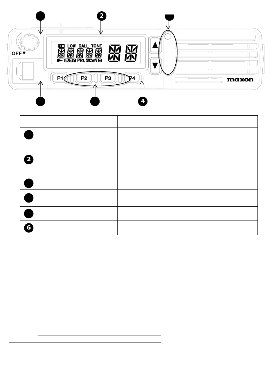
2. DESCRIPTION D'UNITÉ
panneau avant
1 3
6 5
NO NOM DESCRIPTION
1 BOUTON DE CONTRÔLE DU
VOLUME D'AF SOUS TENSION/HORS TENSION, CONTRÔLE DU
VOLUME
AFFICHAGE DE FONCTION
Suite d'écrans LCD.
- Informations sur le canal actuel
- Mode de TX/RX
- Messages
-ANI
3 CLÉS HAUT/BAS Ces clés sont utilisées pour la sélection de canal.
4 CLÉ DE MONITOR/MENU POUSSÉE : SURVEILLEZ LA FONCTION "MARCHE/ARRÊT"
PRISE : MODE DE POSITIONNEMENT D'UTILISATEUR
"MARCHE/ARRÊT"
5 CLÉS PROGRAMMABLES Vous pouvez assigner des fonctions à ces clés dans le
programmeur.
CONNECTEUR DE
MICROPHONE Connectez le microphone à ceci.
Ceci est également utilisé pour programmer et copier.
1 Clé de Secours
2 Commutateur de Sous tension/hors tension et de Contrôle du Volume
Mettez le transmetteur en marche par le commutateur tournant de sous tension/hors tension et
de contrôle du volume dans le sens des aiguilles d'une montre et contrôlez le volume.
3 Antenne de Fouet.
Insérez l'embout fileté de l'antenne dans le connecteur sur le transmetteur. Tournez l'antenne
dans le sens des aiguilles d'une montre pour l'attacher.
4 Tx/Rx Indiquent le LED (couleur 3)
Rouge Sur
Transmission
la programmation et le clonage
écrivent
flasher Batterie Faible
Vert Sur sous-ton en recevant
programmation et clonage lu
flasher Sous-ton Différent en recevant
Orange Sur Réception, surveillant le clonage
[텍스트 입력]
8
5 Earphone/MIC Externe et Embase Acceptant Les Jacks De Programmation
6 Orateur
7 Sortie H/L de Tx
8 Fonction
9 Giclement (SQ)
10 Bouton Choisi de la Manche
Sélectez le canal désiré en appuyant sur En haut et en bas le bouton. Appuyant Sur et maintenant
ce bouton plus longtemps que 1 seconde fera faire un cycle rapidement le transmetteur par les
canaux. Ceci peut être tourné "Marche/Arrêt" en mode de fonction
11 PTTS (Poussée À Parler)
Bouton Maintenez pour transmettre, relâcher pour recevoir.
12 Surveillez le Bouton
Appuyez pour surveiller. Le Maintien plus de 2 secondes garde la fonction de surveillance en
fonction. Appuyez de nouveau ou le Bouton de PTTS pour s'arrêter.
13 Écran LCD
1 2 3 4 5
6
78 9 10 11
NO NOM DESCRIPTION
TX Cette icône apparaît quand le transmetteur transmet.
CANAL FAIBLE
D'ALIMENTATION
ÉLECTRIQUE DE TX
Cette icône apparaît quand l'alimentation électrique de
TX du canal actuel est faible.
3 ALARME D'APPEL Cette icône clignote quand le transmetteur reçoit un
appel.
4 CANAL INFRA-ACOUSTIQUE
DE TON Cette icône apparaît quand le canal actuel a l'option
infra-acoustique du ton (CTCSS, DCS, IDCS).
5 NUMÉRO DE CANAL Le numéro de canal actuel est affiché.
6 AFFICHAGE DES TEXTES Affichez l'information telle que le nom de canal, le
numéro de groupe, le menu, l'ANI, Etc.
[텍스트 입력]
9
DÉFILEMENT Cette icône clignote si la longueur du texte est plus de
6.
8 OCCUPÉ Cette icône apparaît quand le transmetteur reçoit des
signaux.
CANAL PRIORITAIRE Cette icône apparaît si le canal actuel est canal
prioritaire.
BALAYAGE Cette icône clignote pendant le balayage.
LISTE DE BALAYAGE Cette icône apparaît si le canal actuel est enregistré
dans la Liste de Balayage de `'.
14. Connexions de Microphone et de PTTS.
Le microphone et les connexions de PTTS sont par l'intermédiaire du socket de 6 bornes sur le
panneau avant. Le cahier des charges pour le connecteur est affiché dans la table suivante. L'audio
de RX peut être surveillé au jack de 3.5mm sur le panneau arrière.
Connectez
goupillez les
sorties Fonction
1 Données In/out
2 LA TERRE
3 EN d'Instantané
4 DANS DE CROCHET/CLON
5 MIC DEDANS
6 PUISSANCE D'ENTRÉE DE PTT_
7 +8V
8 E/S DE BUSY_